

![Planning Report Ref 14 1252[1]](https://static.fdocuments.in/doc/165x107/577cc66f1a28aba7119e307f/planning-report-ref-14-12521.jpg)


Languages
Pages
Legal

UNIT 1:CELLULAR AND MOBILE COMMUNICATION
Prepared by J.N.Swaminathan, M.Tech; AP/ECE, CHETTINAD TECH, KARUR Page 1
UNIT 1: MULTIPLE ACCESS TECHNIQUES AND CELLULAR CONCEPT
1.1. Introduction:
The radio channel is fundamentally a broadcast medium, therefore signals
transmitted by one user can potentially received by all other users within the range of
the transmitter . However in wireless communication systems it requires stringent
access control to avoid or at least limit the interference between transmissions.
The objective of wireless communication system is to provide communication
channels on demand between a portable radio station and a radio portor base station
that connects the user to the fixed network infrastructure. Design criteria for such
systems include capacity, cost of implementation and quality of service.
All of these measures are influenced by the methodused for providing multiple
access capabilities. Multiple access in wireless systems is based on insulating signals
used in different connections from each other. The support of parallel transmissions
on the uplink and downlink is called multiple access, whereas the exchange of
information in both direction of a connection is referred to as duplexing. Hence
multiple access and duplexing are the methods that facilitate the sharing of the
broadcast communication medium. The necessary insulation is achieved by assigning
to each transmission different components of the domains that contain the signals.
The signal domains most commonly used to provide multiple access capabilities
include the following.
Spatial Domain:
All wireless communication systems exploit the fact that radio signals
experience rapid attenuation during propagation. As the signal strength decays far
away transmitters introduce interference that is negligible compared to the strength of
the desired signal. Directional antennas can be used to enhance the insulation
between the signals.
Frequency Domain:
Signals that occupy non-overlapping frequency bands can be easily separated
using appropriate band pass filters. Hence signals can be transmitted without
interfering with each other. This method of providing multiple access is called as
frequency division multiple access (FDMA).
Time Domain:
Signals can be transmitted in non overlapping time slots in a round-robin
fashion. Thus signals occupy the same frequency band but are separated by their time
of arrival. This multiple access method is called as time division multiple access.
UNIT 1:CELLULAR AND MOBILE COMMUNICATION
Prepared by J.N.Swaminathan, M.Tech; AP/ECE, CHETTINAD TECH, KARUR Page 2
FDMA
TDMA
CDMA
Figure: 1 Multiple access methods for wireless communication systems.
Code Domain:
In code-division multiple access (CDMA) different users employ signals that
have very small cross correlation. Thus correlators can be used to extract individual
signals from a mixture of signals even though they are transmitted simultaneously in
the same frequency band. The term code-division multiple access technique is used to
UNIT 1:CELLULAR AND MOBILE COMMUNICATION
Prepared by J.N.Swaminathan, M.Tech; AP/ECE, CHETTINAD TECH, KARUR Page 3
denote this form of channel sharing. Two forms of CDMA are widely employed,
frequency hopping (FH) and direct sequence (DS).
The principal idea in all these access methods is to employ signals that are
orthogonal or nearly orthogonal. Then correlators that project the received signal into
the subspace of the desired signal can be employed to extract a signal without
interference from other transmissions.
Preference of one access method over another depends largely on the system
characteristic. No single access method is universally preferable. Before going into the
detailed description of the different access methods we discuss briefly the salient
features of some wireless communication systems. This allows us to assess the
relative merits of the access methods in different scenarios.
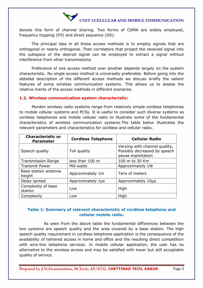
1.2. Wireless communication system characteristic:
Morden wireless radio systems range from relatively simple cordless telephones
to mobile cellular systems and PCSs. It is useful to consider such diverse systems as
cordless telephones and mobile cellular radio to illustrate some of the fundamental
characteristics of wireless communication systems.The table below illustrates the
relevant parameters and characteristics for cordless and cellular radio.
Characteristic or
Parameter Cordless Telephone Cellular Radio
Speech quality Toll quality
Varying with channel quality,
Possibly decreased by speech
pause exploitation
Transmission Range less than 100 m 100 m to 30 Km
Transmit Power Mill watts Approximately 1W
Base station antenna
height Approximately 1m Tens of meters
Delay spread Approximately 1µs Approximately 10µs
Complexity of base station
Low High
Complexity Low High
Table 1: Summary of relevant characteristic of cordless telephone and
cellular mobile radio.
As seen from the above table the fundamental differences between the
two systems are speech quality and the area covered by a base station. The high
speech quality requirement in cordless telephone application is the consequence of the
availability of tethered access in home and office and the resulting direct competition
with wire-line telephone services. In mobile cellular application, the user has no
alternative to the wireless access and may be satisfied with lower but still acceptable
quality of service.
UNIT 1:CELLULAR AND MOBILE COMMUNICATION
Prepared by J.N.Swaminathan, M.Tech; AP/ECE, CHETTINAD TECH, KARUR Page 4
In cordless applications, the transmission ranges is short because the base
station can be simply moved to a conveniently located wire-line access point to
provide wireless network access where desired. In contrast the mobile cellular base
station must provide access for users throughout a large geographical area of
approximately 30 km around the base station. This large coverage is necessary to
economically meet the promise of uninterrupted service to roaming users.
1.3. FREQUENCY DIVISION MULTIPLE ACCESS:
In FDMA, non overlapping frequency bands are allocated to different users on a
continuous time basis. Hence signals assigned to different users are clearly
orthogonal, at least ideally. Practically out of band spectral components cannot be
completely suppressed which leaves signals not quite orthogonal. This necessitates
the use of guard bands between frequency bands to reduce adjacent channel
interference.
It is advantageous to use FDMA with time-division duplexing (TDD) to avoid
simultaneous reception and transmission that would require insulation between
receive and transmit antennas. In this scenario, the base station and portable take
turns using the same frequency band for transmission.
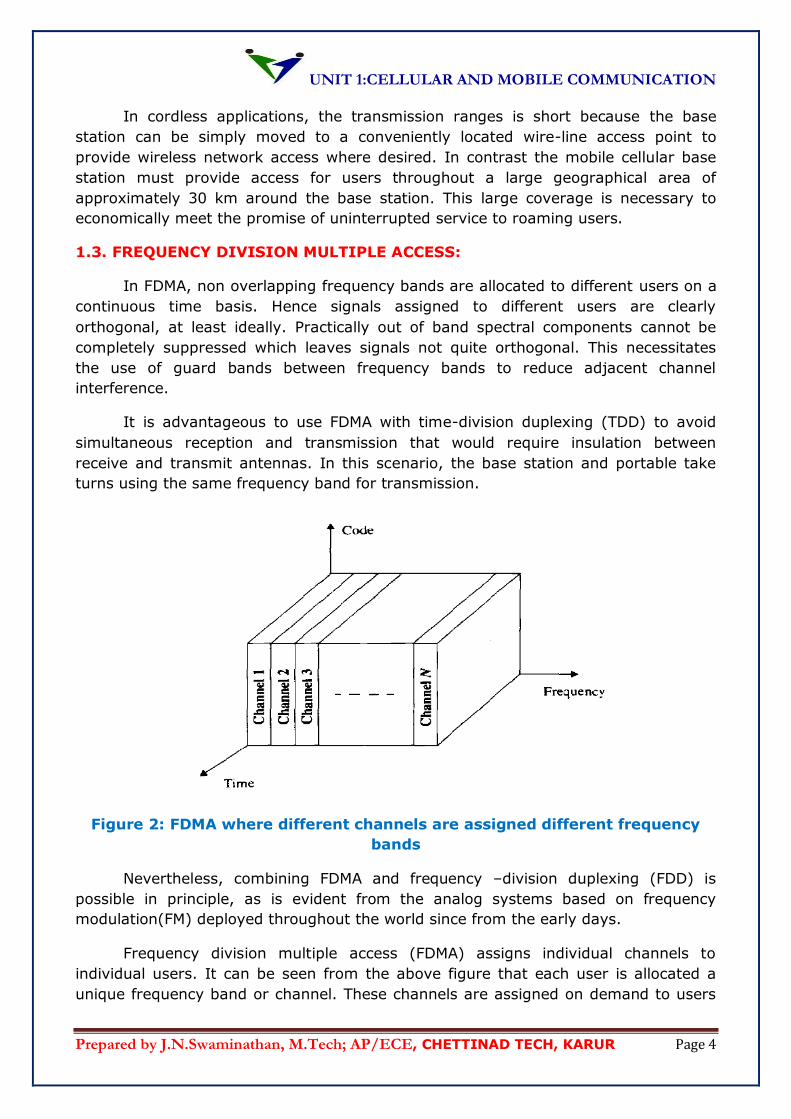
Figure 2: FDMA where different channels are assigned different frequency
bands
Nevertheless, combining FDMA and frequency –division duplexing (FDD) is
possible in principle, as is evident from the analog systems based on frequency
modulation(FM) deployed throughout the world since from the early days.
Frequency division multiple access (FDMA) assigns individual channels to
individual users. It can be seen from the above figure that each user is allocated a
unique frequency band or channel. These channels are assigned on demand to users
UNIT 1:CELLULAR AND MOBILE COMMUNICATION
Prepared by J.N.Swaminathan, M.Tech; AP/ECE, CHETTINAD TECH, KARUR Page 5
who request service. During the period of the call, no other user can share the same
frequency band.
In FDD systems, the users are assigned a channel, as a pair of frequencies, one
frequency is used for the forward channel and the other is used for the reverse
channel.
The features of FDMA are as follows.
The FDMA channel carries one phone circuit at a time.
If an FDMA channel is not in use, then it remains idle and it cannot be used by
other users to increase or share capacity. This feature is essentially a wasted
resource.
After the assignment of a voice channel, the base station and the mobile
transmit simultaneously and continuously.
The bandwidths of FDMA are relatively narrow as each channel; supports one
circuit per carrier. This means that FDMA is usually implemented in narrowband
systems.
The symbol time is large as compared to the delay spread. Thus ISI is low and
it requires less or no equalization.
The complexity is less as compared to TDMA systems.
Since FDMA is a continuous transmission scheme, fewer bits are needed for
overhead purposes as compared to TDMA.
FDMA systems are costly to implement as it requires band pass filters to
eliminate spurious radiation at the base station.
FDMA requires tight RF filtering to minimize adjacent channel interference.
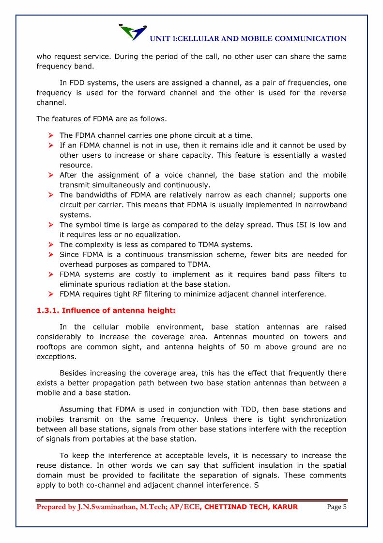
1.3.1. Influence of antenna height:
In the cellular mobile environment, base station antennas are raised
considerably to increase the coverage area. Antennas mounted on towers and
rooftops are common sight, and antenna heights of 50 m above ground are no
exceptions.
Besides increasing the coverage area, this has the effect that frequently there
exists a better propagation path between two base station antennas than between a
mobile and a base station.
Assuming that FDMA is used in conjunction with TDD, then base stations and
mobiles transmit on the same frequency. Unless there is tight synchronization
between all base stations, signals from other base stations interfere with the reception
of signals from portables at the base station.
To keep the interference at acceptable levels, it is necessary to increase the
reuse distance. In other words we can say that sufficient insulation in the spatial
domain must be provided to facilitate the separation of signals. These comments
apply to both co-channel and adjacent channel interference. S
UNIT 1:CELLULAR AND MOBILE COMMUNICATION
Prepared by J.N.Swaminathan, M.Tech; AP/ECE, CHETTINAD TECH, KARUR Page 6
Figure 3: High base station antennas lead to stronger propagation paths
between base stations than between a user set and its base stations.
This problem does not arise in cordless applications. Base station
antennas are of the same height as user sets. Hence interference created by base
station is subject to the same propagation conditions as signals from user sets.
Furthermore in cordless telephone applications there are frequently attenuating
obstacles, such as walls, between base stations, that reduce intracellular interference
further. To overcome intracellular interference adaptive channel management
strategies based on sensing interference levels can be employed.
The number of channels that can be simultaneously supported in a FDMA
system is given by
N = Bt -2Bgaurd / Bc................................ (1)
Where Btis the total spectrum allocation and Bgaurdis the guard band allocated at the
edge of the allocated spectrum and Bcis the channel bandwidth.
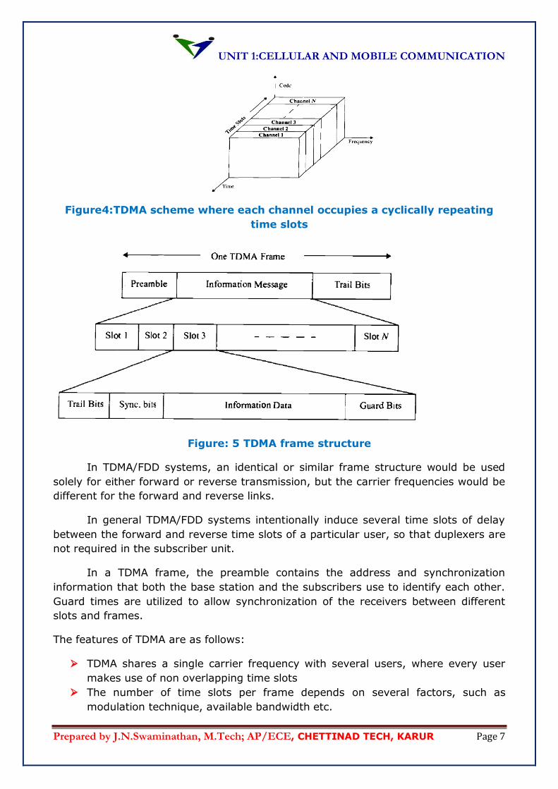
1.4. TIME DIVISION MULTIPLE ACCESS:
Time division multiple access (TDMA) systems divide the radio spectrum into
time slots and in each slot only one user is allowed to either transmit or receive.
As shown in the figure above, each user occupies a cyclically repeating time
slot, so a channel may be thought of as particular time slot that reoccurs every frame,
where N time slots compromise a frame.
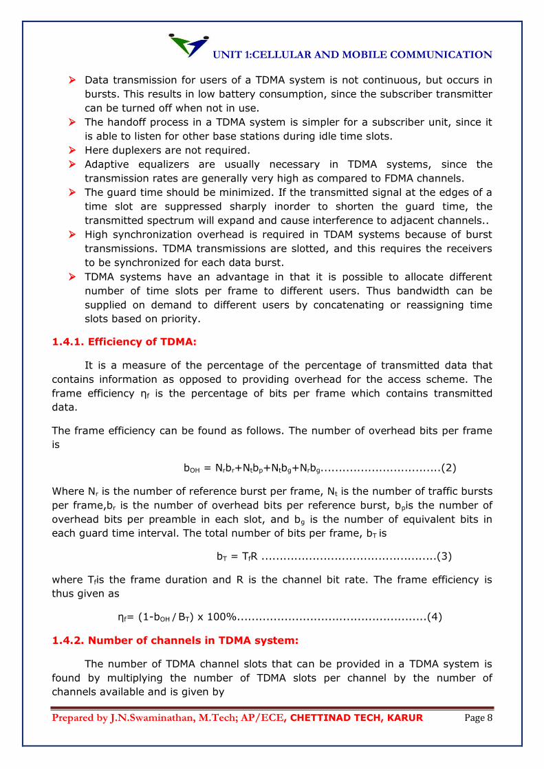
TDMA systems transmit data in a buffer-and-burst method, thus the
transmission for any user is non-continuous. Digital data and digital modulation must
be used with TDMA. The transmission from various users is interlaced into a repeating
frame structure as shown in the figure.It can be seen that a frame consists of a
number of slots. Each frame is made up of a preamble, an information message, and
tail bits. In TDMA/TDD, half of the time slots in the frame information message would
be used for the forward link channels, and the other half would be used for reverse
link channels.
UNIT 1:CELLULAR AND MOBILE COMMUNICATION
Prepared by J.N.Swaminathan, M.Tech; AP/ECE, CHETTINAD TECH, KARUR Page 7
Figure4:TDMA scheme where each channel occupies a cyclically repeating
time slots
Figure: 5 TDMA frame structure
In TDMA/FDD systems, an identical or similar frame structure would be used
solely for either forward or reverse transmission, but the carrier frequencies would be
different for the forward and reverse links.
In general TDMA/FDD systems intentionally induce several time slots of delay
between the forward and reverse time slots of a particular user, so that duplexers are
not required in the subscriber unit.
In a TDMA frame, the preamble contains the address and synchronization
information that both the base station and the subscribers use to identify each other.
Guard times are utilized to allow synchronization of the receivers between different
slots and frames.
The features of TDMA are as follows:
TDMA shares a single carrier frequency with several users, where every user
makes use of non overlapping time slots
The number of time slots per frame depends on several factors, such as
modulation technique, available bandwidth etc.
UNIT 1:CELLULAR AND MOBILE COMMUNICATION
Prepared by J.N.Swaminathan, M.Tech; AP/ECE, CHETTINAD TECH, KARUR Page 8
Data transmission for users of a TDMA system is not continuous, but occurs in
bursts. This results in low battery consumption, since the subscriber transmitter
can be turned off when not in use.
The handoff process in a TDMA system is simpler for a subscriber unit, since it
is able to listen for other base stations during idle time slots.
Here duplexers are not required.
Adaptive equalizers are usually necessary in TDMA systems, since the
transmission rates are generally very high as compared to FDMA channels.
The guard time should be minimized. If the transmitted signal at the edges of a
time slot are suppressed sharply inorder to shorten the guard time, the
transmitted spectrum will expand and cause interference to adjacent channels..
High synchronization overhead is required in TDAM systems because of burst
transmissions. TDMA transmissions are slotted, and this requires the receivers
to be synchronized for each data burst.
TDMA systems have an advantage in that it is possible to allocate different
number of time slots per frame to different users. Thus bandwidth can be
supplied on demand to different users by concatenating or reassigning time
slots based on priority.
1.4.1. Efficiency of TDMA:
It is a measure of the percentage of the percentage of transmitted data that
contains information as opposed to providing overhead for the access scheme. The
frame efficiency ηf is the percentage of bits per frame which contains transmitted
data.
The frame efficiency can be found as follows. The number of overhead bits per frame
is
bOH = Nrbr+Ntbp+Ntbg+Nrbg.................................(2)
Where Nr is the number of reference burst per frame, Nt is the number of traffic bursts
per frame,br is the number of overhead bits per reference burst, bpis the number of
overhead bits per preamble in each slot, and bg is the number of equivalent bits in
each guard time interval. The total number of bits per frame, bT is
bT = TfR ................................................(3)
where Tfis the frame duration and R is the channel bit rate. The frame efficiency is
thus given as
ηf= (1-bOH / BT) x 100%....................................................(4)
1.4.2. Number of channels in TDMA system:
The number of TDMA channel slots that can be provided in a TDMA system is
found by multiplying the number of TDMA slots per channel by the number of
channels available and is given by
UNIT 1:CELLULAR AND MOBILE COMMUNICATION
Prepared by J.N.Swaminathan, M.Tech; AP/ECE, CHETTINAD TECH, KARUR Page 9
m (Btot – 2Bgaurd) N =
Bc .................................................(5)
Where m is the maximum number of TDMA users supported on each radio channel.
1.4.3. Propagation considerations:
In comparison to a FDMA system supporting the same user data rate, the
transmitted data rate in a TDMA system is large by a factor equal to the number of
users sharing the frequency band. This factor is 8 in the pan-European Global System
for Mobile Communication and 3 in the digital advanced mobile phone service (D-
AMPS) system. Thus the symbol duration is reduced by the same factor, and severe
ISI results, atleast in the cellular environment.
To illustrate, consider the example in which each user transmits 25
thousandsymbols per second. Assuming eight users per frequency band leads to a
symbolduration of 5 μs. Even in the cordless application with delay spreads of up to 1
μs,an equalizer may be useful to combat the resulting interference between
adjacentsymbols. In cellular systems, however, the delay spread of up to 20 μs
introducessevere intersymbol interference spanning up to five symbol periods. As the
delayspread often exceeds the symbol duration, the channel can be classified as
frequencyselective, emphasizing the observation that the channel affects different
spectralcomponents differently.The intersymbol interference in cellular TDMA systems
can be so severe thatlinear equalizers are insufficient to overcome its negative effects.
Instead, morepowerful, nonlinear decision feedback or maximum-likelihood sequence
estimationequalizers must be employed.
Furthermore, all of these equalizers requiresome information about the channel
impulse response that must be estimated fromthe received signal by means of an
embedded training sequence. Clearly, the trainingsequence carries no user data and,
thus, wastes valuable bandwidth.
In general, receivers for cellular TDMA systems will be fairly complex. On
thepositive side of the argument, however, the frequency selective nature of the
channelprovides some built-in diversity that makes transmission more robust to
channelfading. The diversity stems from the fact that the multipath components of
thereceived signal can be resolved at a resolution roughly equal to the symbol
duration,and the different multipath components can be combined by the equalizer
duringthe demodulation of the signal. To further improve robustness to channel
UNIT 1:CELLULAR AND MOBILE COMMUNICATION
Prepared by J.N.Swaminathan, M.Tech; AP/ECE, CHETTINAD TECH, KARUR Page 10
fading,coding, and interleaving, slow frequency hopping and antenna diversity can
beemployed as discussed in connection with FDMA.
1.4.4. Initial Channel Assignment:
In both FDMA and TDMA systems, channels should not be assigned to a
mobileon a permanent basis. A fixed assignment strategy would be either extremely
wastefulof precious bandwidth or highly susceptible to co-channel interference.
Instead,channels must be assigned on demand. Clearly, this implies the existence of a
separateuplink channel on which mobiles can notify the base station of their need fora
traffic channel. This uplink channel is referred to as the random-access
channelbecause of the type of strategy used to regulate access to it.
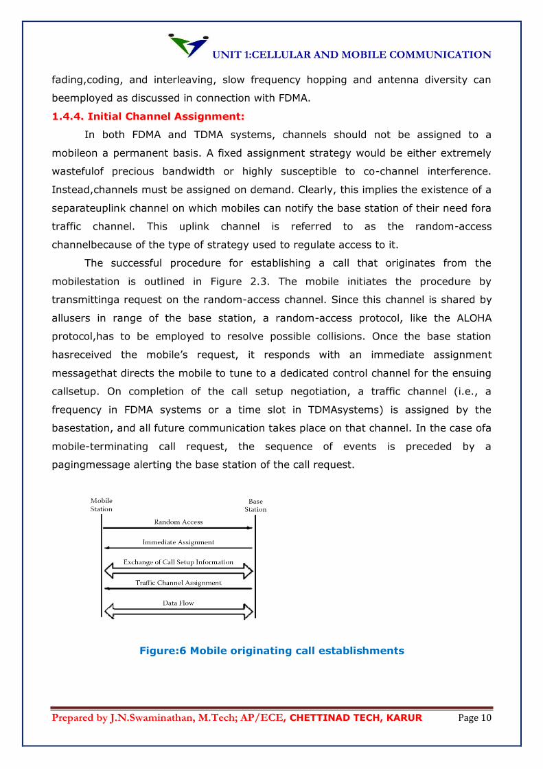
The successful procedure for establishing a call that originates from the
mobilestation is outlined in Figure 2.3. The mobile initiates the procedure by
transmittinga request on the random-access channel. Since this channel is shared by
allusers in range of the base station, a random-access protocol, like the ALOHA
protocol,has to be employed to resolve possible collisions. Once the base station
hasreceived the mobile’s request, it responds with an immediate assignment
messagethat directs the mobile to tune to a dedicated control channel for the ensuing
callsetup. On completion of the call setup negotiation, a traffic channel (i.e., a
frequency in FDMA systems or a time slot in TDMAsystems) is assigned by the
basestation, and all future communication takes place on that channel. In the case ofa
mobile-terminating call request, the sequence of events is preceded by a
pagingmessage alerting the base station of the call request.
Figure:6 Mobile originating call establishments
UNIT 1:CELLULAR AND MOBILE COMMUNICATION
Prepared by J.N.Swaminathan, M.Tech; AP/ECE, CHETTINAD TECH, KARUR Page 11
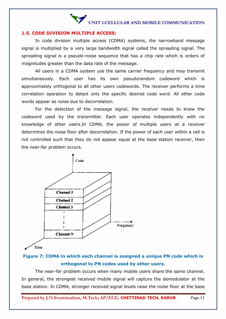
1.5. CODE DIVISION MULTIPLE ACCESS:
In code division multiple access (CDMA) systems, the narrowband message
signal is multiplied by a very large bandwidth signal called the spreading signal. The
spreading signal is a pseudo-noise sequence that has a chip rate which is orders of
magnitudes greater than the data rate of the message.
All users in a CDMA system use the same carrier frequency and may transmit
simultaneously. Each user has its own pseudorandom codeword which is
approximately orthogonal to all other users codewords. The receiver performs a time
correlation operation to detect only the specific desired code word. All other code
words appear as noise due to decorrelation.
For the detection of the message signal, the receiver needs to know the
codeword used by the transmitter. Each user operates independently with no
knowledge of other users.In CDMA, the power of multiple users at a receiver
determines the noise floor after decorrelation. If the power of each user within a cell is
not controlled such that they do not appear equal at the base station receiver, then
the near-far problem occurs.
Figure 7: CDMA in which each channel is assigned a unique PN code which is
orthogonal to PN codes used by other users.
The near-far problem occurs when many mobile users share the same channel.
In general, the strongest received mobile signal will capture the demodulator at the
base station. In CDMA, stronger received signal levels raise the noise floor at the base
UNIT 1:CELLULAR AND MOBILE COMMUNICATION
Prepared by J.N.Swaminathan, M.Tech; AP/ECE, CHETTINAD TECH, KARUR Page 12
station demodulators for the weaker signals, thereby decreasing the probability that
weaker signals will be received.
To combat the near-far problem, power control is usually implemented in most
CDMA systems. Power control is provided by each base station in a cellular system
and assures that each mobile within the base station coverage area provides the same
signal to the base station receiver. This solves the problem of a nearby subscriber
overpowering the base station receiver and drowning out the signals of far away
subscribers.
Power control is implemented at the base station rapidly sampling the radio
signal strength indicator (RSSI) levels of each mobile and then spreading a power
change command over the forward radio link. Despite the use of power control within
each cell, out of cell mobiles provide interference which is not under the control of the
receiving base station.
The features of CDMA are given as follows.
Many users of CDMA systems share the same frequency. Either TDD or FDD
may be used.
CDMA has a soft capacity limit. Increasing the number of users in a CDMA
system raises the noise floor in linear manner. Thus there is no absolute limit
on the number of users in a CDMA system.
Multipath fading may be substantially reduced because the signal is spread over
a large spectrum.
Channel data rates are very high in CDMA systems.
Self jamming is a problem in CDMA systems. It arises from the fact that
spreading the sequences of different users are not exactly orthogonal and
hence during de-spreading nonzero contributions to the receiver decision static
for a desired user arise from the transmission of other users in the system.
The near-far problem occurs at a CDMA receiver if an undesired user has a high
detected power as compared to the desired user.
1.5.1. Propagation Considerations:
Spread spectrum is well suited for wireless communication systems because
ofits built-in frequency diversity. As discussed, in cellular systems the delay
spreadmeasures several microseconds; hence, the coherence bandwidth of the
channel issmaller than 1 MHz. Spreading rates can be chosen to exceed the coherence
bandwidthsuch that the channel becomes frequency selective; that is, different
UNIT 1:CELLULAR AND MOBILE COMMUNICATION
Prepared by J.N.Swaminathan, M.Tech; AP/ECE, CHETTINAD TECH, KARUR Page 13
spectralcomponents are affected unequally by the channel, and only parts of the
signal areaffected by fades.
Expressing the same observation in time domain terms, multipath
componentsare resolvable at a resolution equal to the chip period and can be
combined coherently,for example, by means of a RAKE receiver. An estimate of the
channelimpulse response is required for the coherent combination of multipath
components.This estimate can be gained from a training sequence or by means of a
socalledpilot signal.
Even for cordless telephone systems, operating in environments with sub-
microseconddelay spread and corresponding coherence bandwidths of a few
megahertz,the spreading rate can be chosen large enough to facilitate multipath
diversity. Ifthe combination of multipath components described is deemed too
complex, a simpler,but less powerful, form of diversity can be used that de-correlates
only thestrongest received multipath component and relies on the suppression of
other pathcomponents by the matched filter.
1.5.2. Multiple-Access Interference:
If it is possible to control the relative timing of the transmitted signals, such as
onthe downlink, the transmitted signals can be made perfectly orthogonal, and if
thechannel only adds white Gaussian noise, matched filter receivers are optimal
forextracting a signal from the superposition of waveforms. If the channel is
dispersivebecause of multipath, the signals arriving at the receiver will no longer be
orthogonaland will introduce some multiple-access interference, that is, signal
componentsfrom other signals that are not rejected by the matched filter.On the
uplink, extremely tight synchronization between users to within afraction of a chip
period, which is defined as the inverse of the spreading rate,is generally not possible,
and measures to control the impact of multiple-accessinterference must be taken.
Otherwise, the near–far problem (i.e., the problemof very strong undesired users’
signals overwhelming the weaker signal of thedesired user) can severely decrease
performance. Two approaches are proposed toovercome the near–far problem: power
control with soft handovers and multiuserdetection.
Power control attempts to ensure that signals from all mobiles in a cell arriveat
the base station with approximately equal power levels. To be effective, powercontrol
must be accurate to within about 1 dB and fast enough to compensatefor channel
fading. For a mobile moving at 55 mph and transmitting at 1 GHz,the Doppler
UNIT 1:CELLULAR AND MOBILE COMMUNICATION
Prepared by J.N.Swaminathan, M.Tech; AP/ECE, CHETTINAD TECH, KARUR Page 14
bandwidth is approximately 100 Hz. Hence, the channel changes itscharacteristic
drastically about 100 times per second, and on the order of 1000 bpsmust be sent
from base station to mobile for power control purposes.
As differentmobiles may be subject to vastly different fading and shadowing
conditions, a large dynamic range of about 80 dB must be covered by power control.
Notice that power control on the downlink is really only necessary for mobiles that are
about equidistant from two base stations, and even then neither the update rate nor
the dynamic range of the uplink is required.
The interference problem that arises at the cell boundaries where mobiles
arewithin range of two or more base stations can be turned into an advantage
throughthe idea of soft handover. On the downlink, all base stations within range can
transmitto the mobile, which in turn can combine the received signals to achieve
somegain from the antenna diversity. On the uplink, a similar effect can be obtained
byselecting the strongest received signal from all base stations that receive a user’s
signal.
The base station that receives the strongest signal will also issue power
controlcommands to minimize the transmit power of the mobile. Note, however, that
softhandover requires fairly tight synchronization between base stations, and one of
theadvantages of CDMA over TDMA is lost.
Multiuser detection is still an emerging technique. It is probably best used
inconjunction with power control. The fundamental idea behind this technique is
to model multiple-access interference explicitly and devise receivers that reject or
cancel the undesired signals. A variety of techniques has been proposed, ranging from
optimum maximum likelihood sequence estimation via multistage schemes,
reminiscent of decision feedback algorithms, to linear de-correlating receivers.
1.6. SPREAD SPECTRUM MULTIPLE ACCESS:
Spread spectrum multiple access (SSMA) uses signals which have a
transmission bandwidth that is several orders of magnitude greater than the minimum
required RF bandwidth. A pseudo-noise sequence converts a narrow band signal to a
wide band noise like signal before transmission.
SSMA also provides immunity to multipath interference and robust multiple
access capability. SSMA is not very bandwidth efficient when used by a single user. It
UNIT 1:CELLULAR AND MOBILE COMMUNICATION
Prepared by J.N.Swaminathan, M.Tech; AP/ECE, CHETTINAD TECH, KARUR Page 15
becomes bandwidth efficient when many users share the same spread spectrum
bandwidth
There are two main types of spread spectrum multiple access techniques;
frequency hopped multiple access (FH) and direct sequence multiple access (DH)
1.6.1. Frequency hopped multiple access:
Frequency hopped multiple access (FHMA) is a digital multiple access system in
which the carrier frequencies of the individual users are varied in pseudo-random
fashion within a wide band channel. The digital data is broken into uniform sized
bursts which are transmitted on different carrier frequencies.
The instantaneous bandwidth of any one transmission burst is much smaller
than the total spread bandwidth. The pseudo-random change of the carrier
frequencies of the user randomizes the occupancy of the specific channel at any given
time, thereby allowing for multiple access over a wide range of frequencies.
In the FH receiver a locally generated PN code is used to synchronize the
receivers instantaneous frequency with that of the transmitter. At any given point in
time a frequency hopped signal occupies only a single, relatively narrow channel since
narrow band FM or FSK is used.
The difference between FHMA and traditional FDMA system is that the
frequency hopped signal changes channels at rapid intervals. If the rate of change the
carrier frequency is greater than the symbol rate then the system is referred to as fast
frequency hopping system. If a channel changes at a rate less than or equal to the
symbol rate then the system is referred to as a slow frequency hopping.
A fast frequency hopper may thus be thought of as an FDMA system which
employs frequency diversity. FHMA systems often employ energy efficient constant
envelope modulation.
A frequency hopped system provides a level of security, especially when a large
number of channels are used, since an unintended receiver that does not know the
pseudorandom sequence of frequency slots must retune rapidly to search for the
signal it wishes to intercept.
In addition the FH signal is somewhat immune to fading, since error control
coding and interleaving can be used to protect the frequency hopped signal against
deep fades which may occasionally occur during the hopping sequence. Error control
coding and interleaving can also be combined to guard against erasures which can
occur when two or more users transmit on the same channel at the same time.
UNIT 1:CELLULAR AND MOBILE COMMUNICATION
Prepared by J.N.Swaminathan, M.Tech; AP/ECE, CHETTINAD TECH, KARUR Page 16
1.7.CELLULAR CONCEPT:
The design objective of early mobile radio systems was to achieve a large
coverage area by using a single, high powered transmitter with an antenna mounted
on a tall tower. While this approach achieved very good coverage, it also meant that it
was impossible to reuse those same frequencies throughout the system, since any
attempt to achieve frequency reuse would result in interference.
Owing to the very limited frequency bands, a mobile radio network only has a
relatively small number of speech channels available. For example, the GSM system
has an allocation of 25MHz bandwidth in the 900 MHz frequency range, which
amounts to a maximum of 125 frequency channels each carrier with a carrier
bandwidth of 200 KHz.
The cellular concept was a major breakthrough in solving the problem of
spectral congestion and user capacity. If offered very high capacity in a limited
spectrum allocation without any major technological challenges.
The cellular concept is a system level idea which calls for replacing a single high
power transmitter with many low power transmitters each providing coverage to only
a small portion of the total number of channels available to the entire system, and
nearby base stations are assigned different group of channelsso that the available
channels are assigned to a relatively small number of neighbouring base stations.
Neighbouring base stations are assigned different groups of channels so that the
interference between base stations is minimized.
By systematically spacing base stations and their channel groups throughout a
market, the available channels are distributed throughout the geographic region and
may be re-used as many times as necessary, so long as the interference between co-
channel stations is kept below acceptable levels.
UNIT 1:CELLULAR AND MOBILE COMMUNICATION
Prepared by J.N.Swaminathan, M.Tech; AP/ECE, CHETTINAD TECH, KARUR Page 17
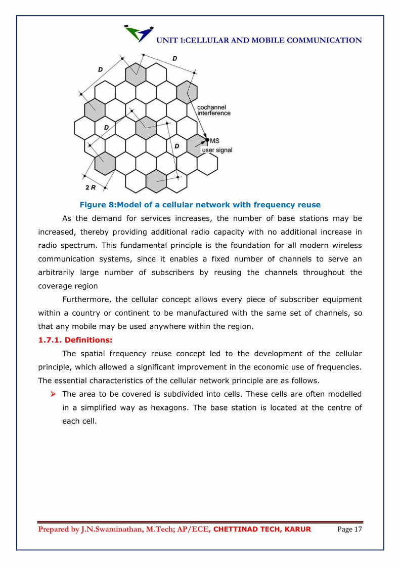
Figure 8:Model of a cellular network with frequency reuse
As the demand for services increases, the number of base stations may be
increased, thereby providing additional radio capacity with no additional increase in
radio spectrum. This fundamental principle is the foundation for all modern wireless
communication systems, since it enables a fixed number of channels to serve an
arbitrarily large number of subscribers by reusing the channels throughout the
coverage region
Furthermore, the cellular concept allows every piece of subscriber equipment
within a country or continent to be manufactured with the same set of channels, so
that any mobile may be used anywhere within the region.
1.7.1. Definitions:
The spatial frequency reuse concept led to the development of the cellular
principle, which allowed a significant improvement in the economic use of frequencies.
The essential characteristics of the cellular network principle are as follows.
The area to be covered is subdivided into cells. These cells are often modelled
in a simplified way as hexagons. The base station is located at the centre of
each cell.
UNIT 1:CELLULAR AND MOBILE COMMUNICATION
Prepared by J.N.Swaminathan, M.Tech; AP/ECE, CHETTINAD TECH, KARUR Page 18
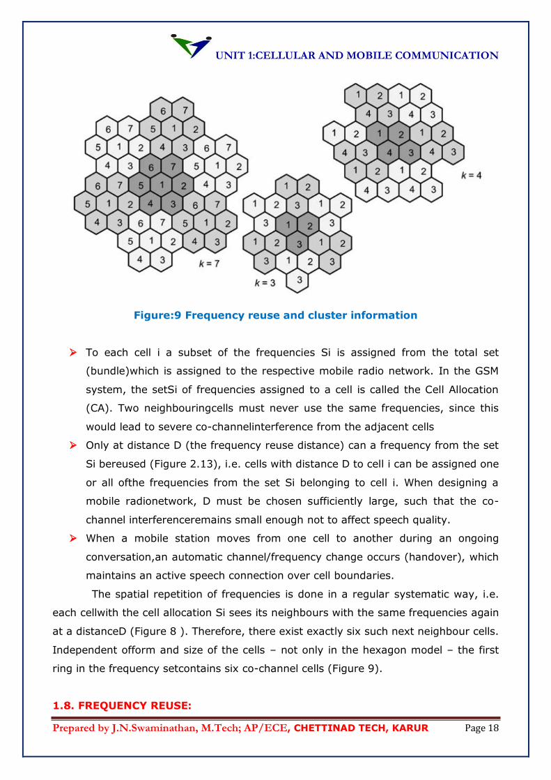
Figure:9 Frequency reuse and cluster information
To each cell i a subset of the frequencies Si is assigned from the total set
(bundle)which is assigned to the respective mobile radio network. In the GSM
system, the setSi of frequencies assigned to a cell is called the Cell Allocation
(CA). Two neighbouringcells must never use the same frequencies, since this
would lead to severe co-channelinterference from the adjacent cells
Only at distance D (the frequency reuse distance) can a frequency from the set
Si bereused (Figure 2.13), i.e. cells with distance D to cell i can be assigned one
or all ofthe frequencies from the set Si belonging to cell i. When designing a
mobile radionetwork, D must be chosen sufficiently large, such that the co-
channel interferenceremains small enough not to affect speech quality.
When a mobile station moves from one cell to another during an ongoing
conversation,an automatic channel/frequency change occurs (handover), which
maintains an active speech connection over cell boundaries.
The spatial repetition of frequencies is done in a regular systematic way, i.e.
each cellwith the cell allocation Si sees its neighbours with the same frequencies again
at a distanceD (Figure 8 ). Therefore, there exist exactly six such next neighbour cells.
Independent ofform and size of the cells – not only in the hexagon model – the first
ring in the frequency setcontains six co-channel cells (Figure 9).
1.8. FREQUENCY REUSE:
UNIT 1:CELLULAR AND MOBILE COMMUNICATION
Prepared by J.N.Swaminathan, M.Tech; AP/ECE, CHETTINAD TECH, KARUR Page 19
Cellular radio systems rely on an intelligent allocation and reuse of channels
throughout a coverage region. Each cellular base station is allocated a group of radio
channels to be used within a small geographical area called a cell.
Base stations in adjacent cells are assigned channel groups which contain
completely different channel than neighbouring cells. The base station antennas are
designed to achieve the desired coverage within the particular cell. By limiting the
coverage area, to within the boundaries of a cell, the same group of channels may be
used to cover different cells that are separated from one another by distances large
enough to keep interference levels within tolerable limits.
The design process of selecting and allocating channel groups for all of the
cellular base stations within a system is called frequency reuse or frequency planning.
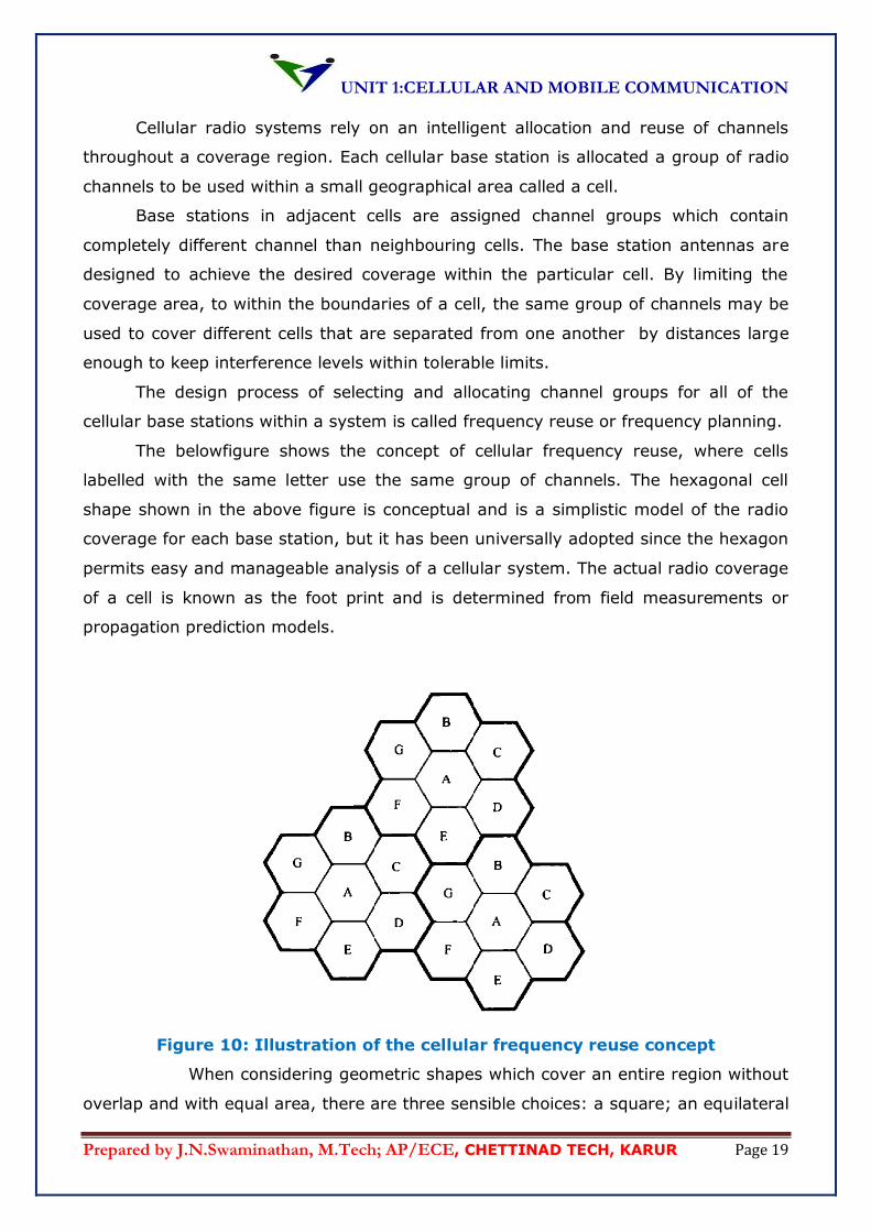
The belowfigure shows the concept of cellular frequency reuse, where cells
labelled with the same letter use the same group of channels. The hexagonal cell
shape shown in the above figure is conceptual and is a simplistic model of the radio
coverage for each base station, but it has been universally adopted since the hexagon
permits easy and manageable analysis of a cellular system. The actual radio coverage
of a cell is known as the foot print and is determined from field measurements or
propagation prediction models.
Figure 10: Illustration of the cellular frequency reuse concept
When considering geometric shapes which cover an entire region without
overlap and with equal area, there are three sensible choices: a square; an equilateral
UNIT 1:CELLULAR AND MOBILE COMMUNICATION
Prepared by J.N.Swaminathan, M.Tech; AP/ECE, CHETTINAD TECH, KARUR Page 20
triangle; and a hexagon. A cell must be designed to serve the weakest mobiles within
the footprint and these are typically located at the edge of a cell. For a given distance
between the centre of a polygon and its farthest perimeter points, the hexagon has
the largest area of the three. Thus by using the hexagon geometry, the fewest
number of cells can cover a geographic region, and the hexagon closely approximates
a circular radiation pattern which could occur for an omni-directional base station
antenna and free space propagation. Of course, the actual cellular footprint is
determined by the contour in which the given transmitter serves the mobiles
successfully.
When using hexagons to model coverage areas, base station transmitters are
depicted as either being in the centre of the cell (centre excited cells) or on three of
the six cell vertices (edge-excited cells). Normally omni-directional antennas are used
in centre-excited cells and sectored directional antennas are used in corner-excited
cells.
Practical considerations usually do not allow base stations to be placed exactly
as they appear in the hexagonal layout. Most system designs permit a base station to
be positioned up to one-fourth the cell radius away from the ideal location.
To understand the frequency reuse concept, consider a cellular system which
has a total of S duplex channels available for use. If each cell is allocated a group of k
channels (k<S), and if the S channels are divided among N cells into unique and
disjoint channel groups which each have the same number of channels, the total
number of available radio channels can be expressed as
S=kN .............................................(6)
The N cells which collectively use the complete set of available frequencies is
called a cluster. If a cluster is replicated M times within the system, the total number
of duplex channels, C can be used as a measure of capacity and is given
C = MkN = MS .................................(7)
As seen from the above equation the capacity of a cellular system is directly
proportional to the number of times a cluster is replicated in a fixed service area. The
factor N is called the cluster size and is typically equal to 4,7 or 12. If the cluster size
N is reduced while the cell size is kept constant, more clusters are required to cover a
given area and hence more capacity is achieved.
A large cluster size indicates that the ratio between the cell radius and the
distance between co-channel cells is large. Conversely, a small cluster size indicates
UNIT 1:CELLULAR AND MOBILE COMMUNICATION
Prepared by J.N.Swaminathan, M.Tech; AP/ECE, CHETTINAD TECH, KARUR Page 21
that co-channel cells are located much closer together. The value for N is a function of
how much interference a mobile or base station can tolerate while maintaining a
sufficient quality of communications.
From a design, viewpoint, the smallest possible value of N is desirable inorder
to maximize capacity over a given coverage area.
The frequency reuse factor of a cellular system is given by 1/N since each cell
within a cluster is only assigned 1/N of the total available channels in the system. Due
to the fact that the hexagonal geometry has exactly six equidistant neighbours are
separated by multiples of 60 degrees, there are only certain cluster sizes and cell
layouts which are possible.
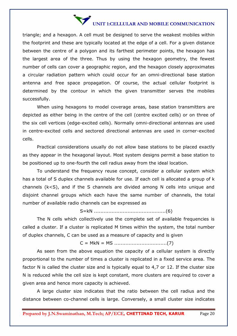
Inorder to tessellate to connect without gaps between adjacent cells the
geometry of hexagons is such that the number of cells per cluster N can only have
values which satisfy equation
N=i2+ij+j2..........................................(8)
where i and j are non-negative integers. To find the nearest co-channel neighbours of
a particular cell we must do the following:
Move i cells along any chain of hexagons and then turn 60 degrees counter-clockwise
and move j cells. This is shown in figure below for i=3 and j=2.
UNIT 1:CELLULAR AND MOBILE COMMUNICATION
Prepared by J.N.Swaminathan, M.Tech; AP/ECE, CHETTINAD TECH, KARUR Page 22
Figure 11: Method of locating co-channel cells in a cellular system
1.9. CHANNEL ASSIGNMENT STRATEGIES:
For efficient utilization of the radio spectrum, a frequency reuse scheme that is
consistent with the objectives of increasing capacity and minimizing interference is
required. A variety of channel assignment strategies have been developed to achieve
these objectives. Channel assignment strategies can be classified as either fixed or
dynamic. The choice of channel assignment strategy impacts the performance of the
system.
In a fixed channel assignment strategy each cell is allocated a predetermined
set of voice channels. Any call attempt with the cell can only be served by the unused
channels in that particular cell. If all the channels in that cell are occupied, the call is
blocked and the subscribers do not receive service. Several variations of fixed channel
strategies exist. In the first approach called the borrowing strategy. A cell is allowed
to borrow channels from a neighbouring cell if all of its own channels are already
occupied. The mobile switching centre (MSC) supervises such borrowing procedures
and ensures that the borrowing of a channel does not disturb or interfere with any of
the calls in progress in the donor cell.
In a dynamic channel assignment strategy voice channels are not allocated to
different cells permanently. Instead of that each time when a call request is made, the
serving base station requires a channel from the MSC. The switch then allocates a
channel to the requested cell following an algorithm that takes into account the
likelihood of future blocking within the cell, the frequency of use of the candidate
channel, the reuse distance of the channel and other cost functions.
Accordingly, the MSC only allocates a given frequency if that frequency is not
presently in use in the cell or any other cell which falls within the minimum restricted
distance of frequency reuse to avoid co-channel interference. Dynamic channel
assignment reduce the chance of call blocking which increases the trunking capacity of
the system, since all the available channels in a market are accessible to all of the
cells. Dynamic channel assignment strategies require the MSC to collect real time data
on channel occupancy, traffic distribution and radio signal strength indicators (RSSI)
of all channels on a continuous basis. This increases the storage and computational
load on the system but provides the advantage of increased channel utilization and
decreased probability of a blocked call.
UNIT 1:CELLULAR AND MOBILE COMMUNICATION
Prepared by J.N.Swaminathan, M.Tech; AP/ECE, CHETTINAD TECH, KARUR Page 23
1.10. HANDOFF STRATEGY:
When a mobile moves into a different cell while a conversation is in progress,
the MSC automatically transfers the call to a new channel belonging to the new base
station. This handoff operation not only involves identifying a new base station, but
also requires that the voice and control signals be allocated to channels associated
with thenew base station.
Processing handoffs is an important task in any cellular radio system. Many
handoff strategies prioritize handoff requests over call initiation requests when
allocating unused channels in a cell site. Handoffs must be performed successfully and
as infrequently as possible, and be imperceptible to the users.
Inorder to meet these requirements, system designers must specify an
optimum signal level at which to initiate a handoff. Once a particular signal level is
specified as the minimum usable signal for acceptable voice quality at the base station
receiver, a slightly stronger signal is used as a threshold at which a handoff is made.
This margin given by Δ = Pr handoff – Prminimum usable, cannot be too large or too small. If Δ
is too large, unnecessary handoffs which burden the MSC may occur and if Δ is too
small, there may be insufficient time to complete a handoff before a call is lost due to
weak signal conditions.
UNIT 1:CELLULAR AND MOBILE COMMUNICATION
Prepared by J.N.Swaminathan, M.Tech; AP/ECE, CHETTINAD TECH, KARUR Page 24
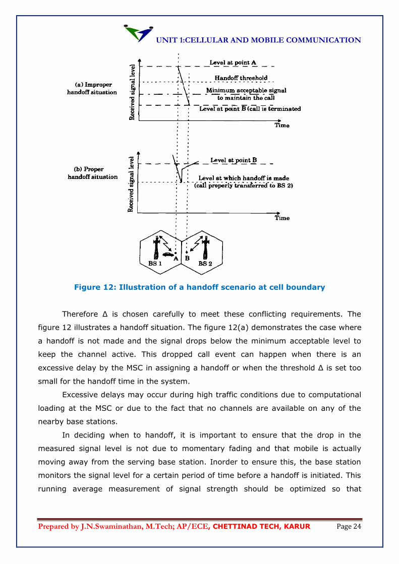
Figure 12: Illustration of a handoff scenario at cell boundary
Therefore Δ is chosen carefully to meet these conflicting requirements. The
figure 12 illustrates a handoff situation. The figure 12(a) demonstrates the case where
a handoff is not made and the signal drops below the minimum acceptable level to
keep the channel active. This dropped call event can happen when there is an
excessive delay by the MSC in assigning a handoff or when the threshold Δ is set too
small for the handoff time in the system.
Excessive delays may occur during high traffic conditions due to computational
loading at the MSC or due to the fact that no channels are available on any of the
nearby base stations.
In deciding when to handoff, it is important to ensure that the drop in the
measured signal level is not due to momentary fading and that mobile is actually
moving away from the serving base station. Inorder to ensure this, the base station
monitors the signal level for a certain period of time before a handoff is initiated. This
running average measurement of signal strength should be optimized so that
UNIT 1:CELLULAR AND MOBILE COMMUNICATION
Prepared by J.N.Swaminathan, M.Tech; AP/ECE, CHETTINAD TECH, KARUR Page 25
unnecessary handoffs are avoided, while ensuring that necessary handoffs are
completed before a call is terminated due to poor signal level.
The length of time needed to decide if a handoff is necessary depends on the
speed at which the vehicle is moving. If slope of the short-term average received
signal level in a given time interval is steep, the handoff should be made quickly.
Information about the vehicle speed which can be useful in handoff decisions can also
be computed from the statistics of the received short time fading signal at the base
station.
The time over which a call may be maintained within a cell, without a handoff is
called the dwell time. The dwell time of a particular user is governed by a number of
factors which include propagation, interference, distance between the subscriber and
the base station and other time varying effects.
1.10.1. Network –Controlled Handoff:
In network-controlled handoff, each base station monitors the signal strength
received from mobiles in their cells and makes periodic measurements of the received
signal from mobiles in their neighbouring cells. The MSC then initiates and completes
the handoff of a mobile as and when it decides. The decision is based on the received
signal strength at the base station serving the mobiles and base stations in
neighbouring cells. Because of its centralized nature, the collection of these
measurements generates large network traffic. This could be reduced to an extent by
making measurements less frequently and by not requiring the neighbouring base
station to send the measurements continually. However, this reduces accuracy. The
execution of handoff by this method takes a few seconds, and for this reason the
method is not preferred by microcellular systems where a quick handoff is desirable.
1.10.2. Mobile-Controlled Handoff:
Mobile-controlled handoff is a highly decentralized method and does not need
anyassistance from the MSC. In this scheme, a mobile monitors signal strength on its
current channel and measures signals received from the neighbouring base stations. It
receives BER and signal strength information about uplink channels from its serving
base stations. Based on all this information, it initiates the handoff process by
requesting the neighbouring base for allocation of a low-interference channel. The
method has a handoff execution time on the order of 100 ms and is suitable for
microcell systems.
1.10.3. Mobile-Assisted Handoff:
UNIT 1:CELLULAR AND MOBILE COMMUNICATION
Prepared by J.N.Swaminathan, M.Tech; AP/ECE, CHETTINAD TECH, KARUR Page 26
In MAHO methods, as the name suggests, a mobile helps the network in the
handoffdecision making by monitoring the signal strength of its neighbouring base
stationsand passing the results to the MSC via its serving base station. The handoff is
initiatedand completed by the network. The execution time is on the order of 1 s.
1.10.4. Hard Handoff and Soft Handoff:
Handoff may be classified into hard handoff and soft handoff. During hard
handoff,the mobile can communicate only with one base station. The communication
linkgets broken with the current base station before the new one is established, and
thereis normally a small gap in communication during the transition. In the process of
soft handoff, the mobile is able to communicate with more than one base station. It
receives signals from more than one base station, and the received signals are
combined after appropriate delay adjustment. Similarly, more than one station
receives signals from mobiles, and the network combines different signals. This
scheme is also known as macroscopic diversity and is mostly employed by CDMA
systems. Hard handoff, on the other hand, is more appropriate for TDMA and FDMA
systems. It is also simple to implement compared with soft handoff.
However it may lead to unnecessary handoff back and forth between two base
stations when the signals from two base stations fluctuate. The situation may arise
when a mobile, currently being served, for example, by base 1 receives a stronger
signal from, say, base 2 and is handed over to base 2. Immediately after that, it
receives a stronger signal from base 1 compared to what it receives from base 2,
causing a handoff. This phenomenon, known as the ping-pong effect, may continue
for some time and is undesirable because every handoff has a cost associated with it,
requiring network signalling of varying amount for authentication, database updates,
and circuit switching, and so on. This is avoided by using a hysteresis margin such
that the handoff isnot initiated until the difference between the signals received from
the two base stations is more than the margin. For example, if the margin is ΔdB,
then the handoff is initiated when the signal received by the mobile from base 2 is
ΔdB more than that from base 1.
1.11. INTERFERENCE AND SYSTEM CAPACITY:
Interference is the major limiting factor in the performance of cellular radio
systems. The various sources of interference include another mobile in the same cell,
a call in progress in a neighbouring cell, other base stations operating in the same
UNIT 1:CELLULAR AND MOBILE COMMUNICATION
Prepared by J.N.Swaminathan, M.Tech; AP/ECE, CHETTINAD TECH, KARUR Page 27
frequency band, or any non-cellular system which involuntarily leaks energy into the
cellular frequency band.
Interference results in cross talks. On control channels interference leads to
missed and blocked calls due to errors in digital signalling. Interference has become a
blockage in increasing the capacity and is often responsible for dropped calls. The two
major types of system generated interference are co-channel interference and
adjacent channel interference. Even though the interference are generated within the
cellular system they are very difficult to control in practice due to random propagation
effects. Practically out of band interference results due to the close proximity of base
stations to provide comparable coverage to customers.
1.11.1 Co-channel interference and system capacity:
Co-channels are the cells that use the same set of frequencies in a given
coverage area and the interference resulting from these cells are called as co-channel
interference. Co-channel interference cannot be combated by increasing the carrier
power of the transmitter. Increasing the transmitter power induces interference in the
neighbouring cells. To reduce co-channel interference, co-channel cells must be
physically separated by a minimum distance to provide sufficient isolation due to
propagation.
When the size of each cell is approximately the same, and the base stations
transmit the same power, the co-channel interference ratio is independent of the
transmitted power and becomes a function of the radius of the cell (R) and the
distance between the centres of the nearest co-channel cells (D). By increasing the
ratio D/R, the spatial separation between co-channel cells relative to the coverage
distance of a cell is increased. Thus interference is reduced from improved isolation of
RF energy from the co-channel cell. The parameter called the co-channel reuse ratio
(Q) is related to the cluster size. For a hexagonal geometry
Q = D/R = √3N ................................(9)
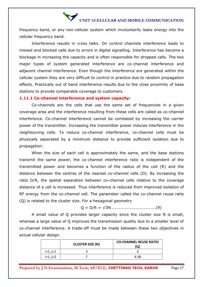
A small value of Q provides larger capacity since the cluster size N is small,
whereas a large value of Q improves the transmission quality due to a smaller level of
co-channel interference. A trade-off must be made between these two objectives in
actual cellular design.
CLUSTER SIZE (N) CO-CHANNEL REUSE RATIO
(Q)
i=1, j=1 3 3
i=1, j=2 7 4.58
UNIT 1:CELLULAR AND MOBILE COMMUNICATION
Prepared by J.N.Swaminathan, M.Tech; AP/ECE, CHETTINAD TECH, KARUR Page 28
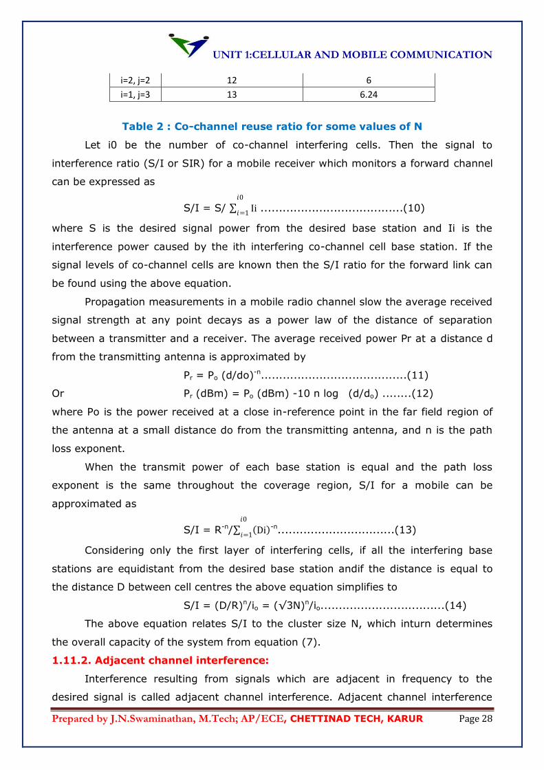
i=2, j=2 12 6
i=1, j=3 13 6.24
Table 2 : Co-channel reuse ratio for some values of N
Let i0 be the number of co-channel interfering cells. Then the signal to
interference ratio (S/I or SIR) for a mobile receiver which monitors a forward channel
can be expressed as
S/I = S/ Ii𝑖0
𝑖=1 .......................................(10)
where S is the desired signal power from the desired base station and Ii is the
interference power caused by the ith interfering co-channel cell base station. If the
signal levels of co-channel cells are known then the S/I ratio for the forward link can
be found using the above equation.
Propagation measurements in a mobile radio channel slow the average received
signal strength at any point decays as a power law of the distance of separation
between a transmitter and a receiver. The average received power Pr at a distance d
from the transmitting antenna is approximated by
Pr = Po (d/do)-n........................................(11)
Or Pr (dBm) = Po (dBm) -10 n log (d/do) ........(12)
where Po is the power received at a close in-reference point in the far field region of
the antenna at a small distance do from the transmitting antenna, and n is the path
loss exponent.
When the transmit power of each base station is equal and the path loss
exponent is the same throughout the coverage region, S/I for a mobile can be
approximated as
S/I = R-n/ Di 𝑖0
𝑖=1-n................................(13)
Considering only the first layer of interfering cells, if all the interfering base
stations are equidistant from the desired base station andif the distance is equal to
the distance D between cell centres the above equation simplifies to
S/I = (D/R)n/io = (√3N)n/io..................................(14)
The above equation relates S/I to the cluster size N, which inturn determines
the overall capacity of the system from equation (7).
1.11.2. Adjacent channel interference:
Interference resulting from signals which are adjacent in frequency to the
desired signal is called adjacent channel interference. Adjacent channel interference
UNIT 1:CELLULAR AND MOBILE COMMUNICATION
Prepared by J.N.Swaminathan, M.Tech; AP/ECE, CHETTINAD TECH, KARUR Page 29
results from imperfect receiver filters which allow nearby frequencies to leak into the
passband.
The problem can be particularly serious if an adjacent channel user is
transmitting in very close range to a subscriber’s receiver, while the receiver attempts
to receive a base station on the desired channel. This is referred to as the near-far
effect, where a near-by transmitter captures the receiver of the subscriber.
Alternatively, the near-far effect occurs when a mobile close to a base station
transmits on a channel close to one being used by a weak mobile. The base station
may have difficulty in discriminating the desired mobile user from the bleedover
caused by the close adjacent mobile.
Adjacent channel interference can be minimized through careful filtering and
channel assignments. Since each cell is given only a fraction of the available channels,
a cell need not be assigned channels which are all adjacent in frequency. By keeping
the frequency separation between each channel in a given cell as large as possible,
the adjacent channel interference may be reduced considerably. Thus instead of
assigning channels which form a contiguous band of frequencies within a particular
cell, channels are allocated such that the frequency separation between channels in a
given cell is maximized.
By sequencing assigning successive channels in the frequency band to different
cells, many channel allocation schemes are able to separate adjacent channels in a
cell by as many as N channel bandwidths,where N is the cluster size.
If the frequency reuse factor is small, the separation between adjacent
channels may not be sufficient to keep the adjacent channel interference level within
tolerable limits.
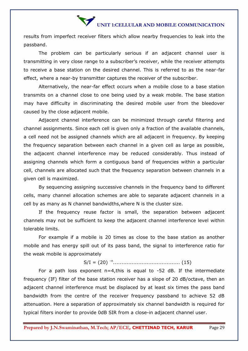
For example if a mobile is 20 times as close to the base station as another
mobile and has energy spill out of its pass band, the signal to interference ratio for
the weak mobile is approximately
S/I = (20) –n........................................ (15)
For a path loss exponent n=4,this is equal to -52 dB. If the intermediate
frequency (IF) filter of the base station receiver has a slope of 20 dB/octave, then an
adjacent channel interference must be displaced by at least six times the pass band
bandwidth from the centre of the receiver frequency passband to achieve 52 dB
attenuation. Here a separation of approximately six channel bandwidth is required for
typical filters inorder to provide 0dB SIR from a close-in adjacent channel user.
UNIT 1:CELLULAR AND MOBILE COMMUNICATION
Prepared by J.N.Swaminathan, M.Tech; AP/ECE, CHETTINAD TECH, KARUR Page 30
This implies that a channel separation greater than six is needed to bring the
adjacent channel interference to an acceptable level, or tighter base station filters are
needed when close-in and distant users share the same cell. In practice, each base
station receiver is preceded by a high Q cavity filter inorder to reject adjacent channel
interference.
1.11.3. Power control for reducing interference:
In practical radio systems the power level transmitted by every subscriber unit
are under constant control by the serving base stations. This is done to ensure that
each mobile transmits the smallest power necessary to maintain a good quality link on
the reverse channel.
Power control not only helps prolong battery life for the subscriber unit but also
dramatically reduces the reverse channel S/I in the system
1.12. TRUNKINGAND GRAGE OF SERVICE:
Cellular radio systems rely on trunking to accommodate a large number of
users in a limited radio spectrum. The concept of trunking allows a large number of
users to share the relatively small number of channels in a cell by providing access to
each user, on demand from a pool of available channels.
In a trunked radio system, each user is allocated a channel on a per call basis,
and upon termination of the call, the previously occupied channel is immediately
returned to the pool of available channels.
Trunking exploits the statistical behaviour of users so that a fixed number of
channels or circuits may accommodate a large random user community. The trunking
theory is used to determine the number of telephone circuits that needed to be
allocated for office buildings with hundreds of telephones, and the same principle is
used in designing cellular radio systems.
There is a trade-off between the number of available telephone circuits and the
likelihood of a particular user finding that no circuits are available during the peak
calling time. As the number of phone line decreases, it becomes more likely that all
circuits will be busy for a particular user.
In a trunked mobile radio system when a particular user request service and all
of the radio channels are already in use, or the user is blocked, or denied access to
the system. In some systems a queue may be used to hold the requesting users until
a channel becomes available.
UNIT 1:CELLULAR AND MOBILE COMMUNICATION
Prepared by J.N.Swaminathan, M.Tech; AP/ECE, CHETTINAD TECH, KARUR Page 31
To design trunked radio systems that can handle a specific capacity at a specific
grade of service is essential to understand trunking theory and queuing theory. The
fundamentals of trunking theory were explained by Erlang. Today the measure of the
traffic intensity bears his name.
On Erlang represents the amount of traffic intensity carried by a channel that is
completely occupied. For example a radio channel that is continuously occupied for
thirty minutes during an hour carries 0.5 Erlangs of traffic.
The grade of service (GOS) is the measure of the ability of a user to access a
trunked system during the busiest hour during a weak, month or year. The grade of
service is a bench mark used to define the desired performance of a particular trunked
system by specifying a desired likelihood of a user obtaining channel access given a
specific number of channels available in the system. GOS is typically given as the
likelihood that a call is blocked or the likelihood of a call experiencing a delay greater
than a certain queuing time.
A number of definitions are listed below are used in trunking theory to make
capacity estimates in trunked systems.
Set-up time:the time required to allocate a trunked radio channel to a requesting
user
Blocked call:Call which cannot be completed at time of request, due to congestion.
Also referred to as lost call.
Holding time:average duration of a typical call and is denoted by H in seconds.
Traffic intensity:Measure of channel time utilization, which is average channel
occupancy measured in Erlangs. This is a dimensionless quantity and may be used to
measure the time utilization of single or multiple channels and is denoted by A.
Load:Traffic intensity across the entire trunked radio system, measured in Erlangs.
Grade of service:a measure of congestion which is specified as the probability of a
call being blocked, or the probability of a call being delayed beyond a certain amount
of time.
Request rate:The average number of call requests per unit time and is denoted by λ
seconds-1
The traffic intensity offered by each user is equal to the cal request rate
multiplied by the holding time. That is each user generates a traffic intensity of Au
Erlangs given by
Au = λH...................................... (16)
UNIT 1:CELLULAR AND MOBILE COMMUNICATION
Prepared by J.N.Swaminathan, M.Tech; AP/ECE, CHETTINAD TECH, KARUR Page 32
where H is the average duration of a call and λ is the average number of call request
per time. For a system containing U users and an unspecified number of channels, the
total offered traffic intensity A is given as
A = UAu .......................................(17)
Further more in a C channel trunked system, if the traffic is equally distributed
among the channels, then the traffic intensity per channel Ac is given by
Ac = U Au/C ..................................(18)
Note that the offered traffic is not necessarily the traffic which is carried by the
trunked system, only that which is offered to the trunked system. When the offered
traffic capacity exceeds the maximum capacity of the system, the carried traffic
becomes limited due to the limited capacity.
There are two types of trunked systems which are commonly used. The first
type offers no queuing for call requests. That is for every user who requests service, it
is assumed there is no set up time and the user is given immediate access to a
channel if one is available. If no channels are available, the requesting user is blocked
without access and is free to try again later. This type of trunking is called blocked
calls cleared and assumes that calls arrive as determined by a Poisson distribution.
Further more it is assumed that there are an infinite number of users as wellas
the following:
(a) Therearememoryless arrivals of requests implying that all users,
including blocked users, may request a channel at any time.
(b) The probability of a user occupying a channel is exponentially distributed
so that longer calls are likely to occur as described by an exponential
distribution.
(c) There are finite number of channels available in trunking pool.
This is known as M/M/m queue, and leads to derivation of the Erlang B formula. The
Erlang B formula determines the probability that a call is blocked and is a measure of
GOS for a trunked system which provides no queuing for blocked calls. The Erlang B
formula is derived as follows.
Pr blocking = =𝐴𝑐
𝐶!
𝐴𝑘
𝑘!
𝑐
𝑘=𝑜
= GOS .....................(19)
where C is the number of trunked channels offered by a radio system and A is the
total offered traffic.
UNIT 1:CELLULAR AND MOBILE COMMUNICATION
Prepared by J.N.Swaminathan, M.Tech; AP/ECE, CHETTINAD TECH, KARUR Page 33
The second type of trunked system is one in which a queue is provided to hold
calls which are blocked. If a channel is not available immediately, the call request may
be delayed until a channel becomes available. This type of trunking is called blocked
calls delayed and its measure of GOS is defined as the probability that after a call is
blocked after waiting a specific length of time in queue. To find the GOS, it is first
necessary to find the likelihood that a call is initially delayed access to the system.
The likelihood of a call not having immediate access to a channel is determined
by the Erlang C formula given by
Pr [delay>0] = 𝐴𝑐
𝐴𝑐+𝐶! 1−𝐴
𝐶
𝐴𝑘
𝑘 !
𝐶−1
𝑘=𝑜
.......................(20)
If no channels are immediately available the call is delayed, and the probability that a
delayed call is forced to wait more than t seconds is given by the probability that a call
is delayed, multiplied by the conditional probability that the delay is greater than t
seconds. The GOS of a trunked system where blocked calls are delayed is hence given
by
Pr [delay>t] = Pr [delay>0] Pr [delay >t / delay >0]......(21)
= Pr [delay >0]exp(-(C-A)t/H)
The average delay D for all calls in a queued system is given by
D = Pr [delay > 0] = H
C−A.................................................(22)
where the average delay for those calls which are queued is given by H
C−A
1.13. IMPROVING CAPACITY IN CELLULAR SYSTEMS:
As the demand for wireless service increases, the number of channels assigned to a
cell eventually becomes insufficient to support the required number of users. At this
point, cellular design techniques are needed to provide more channels per unit
coverage area.
Techniques such as cell splitting, sectoring and coverage zone approaches are
used in practice to expand the capacity of cellular systems. Cell splitting allows an
orderly growth of the cellular system. Sectoring uses directional antennas further to
control the interference and frequency reuse of channels. The zone microcell concept
distributes the coverage of a cell and extends the cell boundary to hard-to –reach
places. While cell splitting increases the number of base stations inorder to increase
capacity, sectoring and zone microcells rely on base station antenna placements to
UNIT 1:CELLULAR AND MOBILE COMMUNICATION
Prepared by J.N.Swaminathan, M.Tech; AP/ECE, CHETTINAD TECH, KARUR Page 34
improve capacity by reducing co-channel interference. Cell splitting and zone microcell
techniques do not suffer the trunking inefficiencies experienced by sectored cells, and
enable the base station to oversee all handoff chores related to the microcells, thus
reducing the computational load at MSC.
1.13.1. Cell splitting:
Cell splitting is the process of subdividing a congested cell into smaller cells, each with
its own base station and a corresponding reduction in antenna height and transmitter
power.
Cell splitting increases the capacity of a cellular system since it increases the
number of times that channels are reused. By defining new cells which have a smaller
radius than the original cells and by installing these smaller cells between the existing
cells, capacity increases due to the additional number of channels per unit area.
Inorder to cover the entire service area with smaller cells, approximately four
times as many cells would be required. This can be easily shown by considering a
circle with radius R. The area covered by such a circle is four times as large as the
area covered by a circle with radius R/2. The increased number of cells would increase
the number of clusters over the coverage region, which inturn would increase the
number of channels and thus capacity in the coverage area. Cell splitting allows a
system to grow by replacing large cells with smaller cells, while not upsetting the
channel allocation scheme required to maintain a minimum co-channel reuse ratio Q
between co-channel cells.
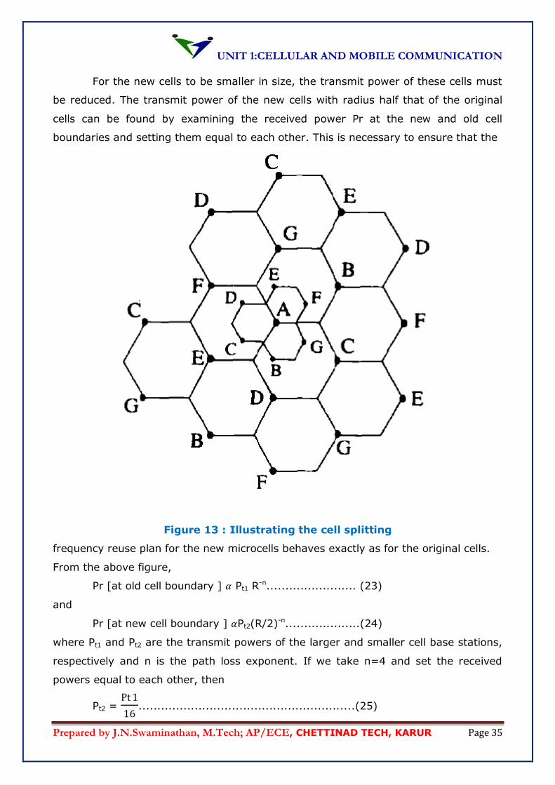
An example of cell splitting is shown in figure below. Here the base stations
are [placed at the corners of the cells, and the area served b y the base station A is
assumed to be saturated with traffic. New base stations are therefore needed on the
region to increase the number of channels in the area and to reduce the area served
by the single base station.
In the figure given below, the original base station A has been surrounded by
six new microcell base stations. The smaller cells were added in such a way as to
preserve the frequency reuse plan of the system.
For example the microcell base station labelled G was placed halfway between
two large base stations utilizing the same channel set G. This is also the case for other
microcells. Cell splitting merely scales the geometry of the cluster. In this case, the
radius of each new microcell is half that of the original cell.
UNIT 1:CELLULAR AND MOBILE COMMUNICATION
Prepared by J.N.Swaminathan, M.Tech; AP/ECE, CHETTINAD TECH, KARUR Page 35
For the new cells to be smaller in size, the transmit power of these cells must
be reduced. The transmit power of the new cells with radius half that of the original
cells can be found by examining the received power Pr at the new and old cell
boundaries and setting them equal to each other. This is necessary to ensure that the
Figure 13 : Illustrating the cell splitting
frequency reuse plan for the new microcells behaves exactly as for the original cells.
From the above figure,
Pr [at old cell boundary ] 𝛼 Pt1 R-n........................ (23)
and
Pr [at new cell boundary ] 𝛼Pt2(R/2)-n....................(24)
where Pt1 and Pt2 are the transmit powers of the larger and smaller cell base stations,
respectively and n is the path loss exponent. If we take n=4 and set the received
powers equal to each other, then
Pt2 = Pt1
16..........................................................(25)
UNIT 1:CELLULAR AND MOBILE COMMUNICATION
Prepared by J.N.Swaminathan, M.Tech; AP/ECE, CHETTINAD TECH, KARUR Page 36
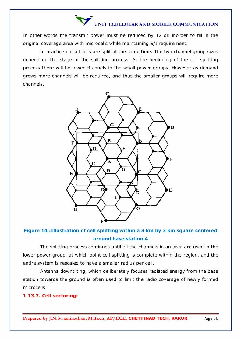
In other words the transmit power must be reduced by 12 dB inorder to fill in the
original coverage area with microcells while maintaining S/I requirement.
In practice not all cells are split at the same time. The two channel group sizes
depend on the stage of the splitting process. At the beginning of the cell splitting
process there will be fewer channels in the small power groups. However as demand
grows more channels will be required, and thus the smaller groups will require more
channels.
Figure 14 :Illustration of cell splitting within a 3 km by 3 km square centered
around base station A
The splitting process continues until all the channels in an area are used in the
lower power group, at which point cell splitting is complete within the region, and the
entire system is rescaled to have a smaller radius per cell.
Antenna downtilting, which deliberately focuses radiated energy from the base
station towards the ground is often used to limit the radio coverage of newly formed
microcells.
1.13.2. Cell sectoring:
UNIT 1:CELLULAR AND MOBILE COMMUNICATION
Prepared by J.N.Swaminathan, M.Tech; AP/ECE, CHETTINAD TECH, KARUR Page 37
Cell splitting achieves capacity improvement by essentially rescaling the
system. By decreasing the cell radius R and keeping the co-channel reuse ratio d/R
unchanged, cell splitting increases the number of channels per unit area.
However another way to improve capacity is to keep the cell radius unchanged
and seek the methods to decrease the D/R ratio. In this approach capacity
improvement is achieved by reducing the number of cells in a cluster and thus
increasing the frequency reuse. Inorder to do this it is necessary to reduce the relative
interference without decreasing the transmit power.
The co-channel interference in a cellular system may be decrease by replacing
a single omni-directional antenna at the base station by several directional antennas
each radiating within a specific sector. By using directional antennas, a given cell will
receive interference and transmit with only a fraction of the available co-channel cells.
The technique for decreasing co-channel interference and thus increasing system
capacity by using directional antennas is called sectoring. The factor by which the co-
channel interference is reduced depends on the amount of sectoring used. A cell is
normally partitioned into three 120°sectors or six 60° sectors as shown in figure 15 (a)
and (b).
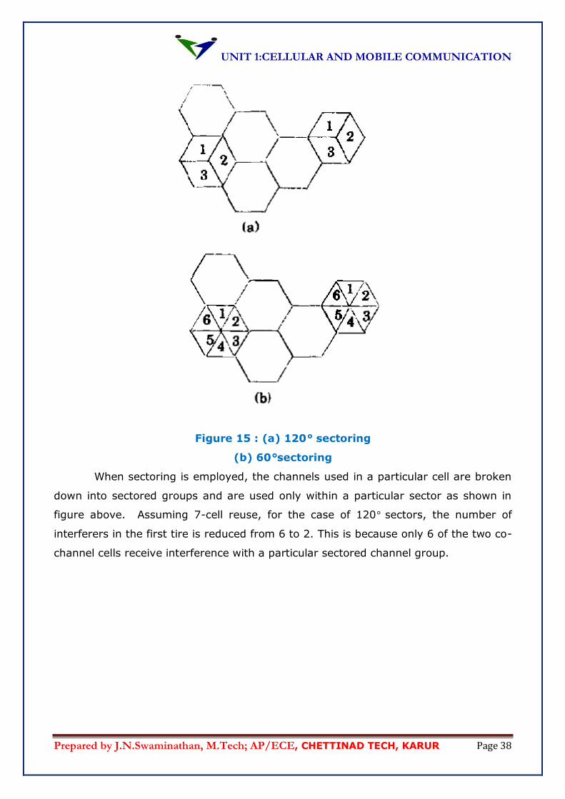
UNIT 1:CELLULAR AND MOBILE COMMUNICATION
Prepared by J.N.Swaminathan, M.Tech; AP/ECE, CHETTINAD TECH, KARUR Page 38
Figure 15 : (a) 120° sectoring
(b) 60°sectoring
When sectoring is employed, the channels used in a particular cell are broken
down into sectored groups and are used only within a particular sector as shown in
figure above. Assuming 7-cell reuse, for the case of 120° sectors, the number of
interferers in the first tire is reduced from 6 to 2. This is because only 6 of the two co-
channel cells receive interference with a particular sectored channel group.
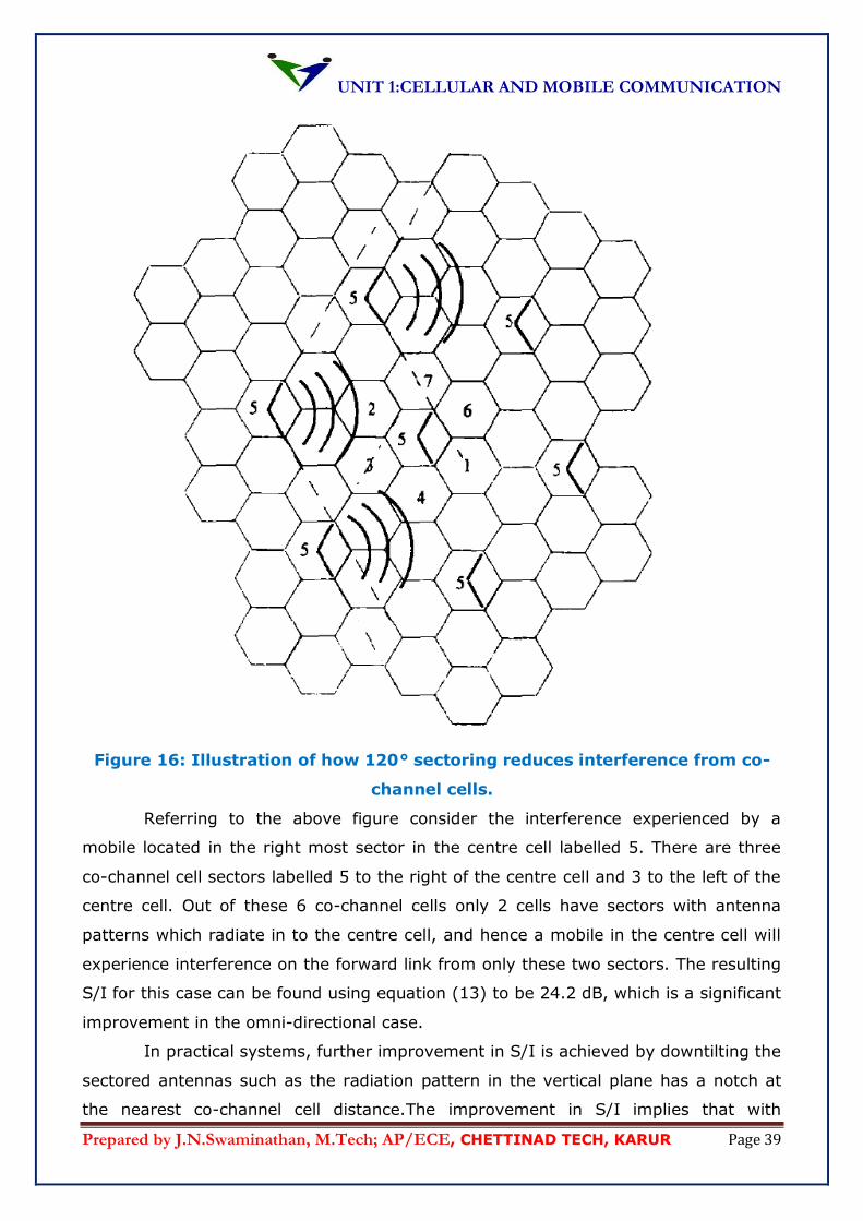
UNIT 1:CELLULAR AND MOBILE COMMUNICATION
Prepared by J.N.Swaminathan, M.Tech; AP/ECE, CHETTINAD TECH, KARUR Page 39
Figure 16: Illustration of how 120° sectoring reduces interference from co-
channel cells.
Referring to the above figure consider the interference experienced by a
mobile located in the right most sector in the centre cell labelled 5. There are three
co-channel cell sectors labelled 5 to the right of the centre cell and 3 to the left of the
centre cell. Out of these 6 co-channel cells only 2 cells have sectors with antenna
patterns which radiate in to the centre cell, and hence a mobile in the centre cell will
experience interference on the forward link from only these two sectors. The resulting
S/I for this case can be found using equation (13) to be 24.2 dB, which is a significant
improvement in the omni-directional case.
In practical systems, further improvement in S/I is achieved by downtilting the
sectored antennas such as the radiation pattern in the vertical plane has a notch at
the nearest co-channel cell distance.The improvement in S/I implies that with
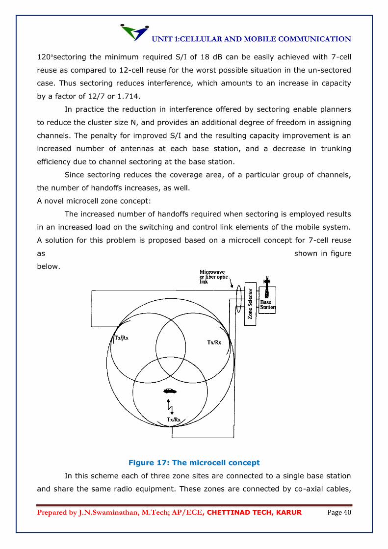
UNIT 1:CELLULAR AND MOBILE COMMUNICATION
Prepared by J.N.Swaminathan, M.Tech; AP/ECE, CHETTINAD TECH, KARUR Page 40
120°sectoring the minimum required S/I of 18 dB can be easily achieved with 7-cell
reuse as compared to 12-cell reuse for the worst possible situation in the un-sectored
case. Thus sectoring reduces interference, which amounts to an increase in capacity
by a factor of 12/7 or 1.714.
In practice the reduction in interference offered by sectoring enable planners
to reduce the cluster size N, and provides an additional degree of freedom in assigning
channels. The penalty for improved S/I and the resulting capacity improvement is an
increased number of antennas at each base station, and a decrease in trunking
efficiency due to channel sectoring at the base station.
Since sectoring reduces the coverage area, of a particular group of channels,
the number of handoffs increases, as well.
A novel microcell zone concept:
The increased number of handoffs required when sectoring is employed results
in an increased load on the switching and control link elements of the mobile system.
A solution for this problem is proposed based on a microcell concept for 7-cell reuse
as shown in figure
below.
Figure 17: The microcell concept
In this scheme each of three zone sites are connected to a single base station
and share the same radio equipment. These zones are connected by co-axial cables,
UNIT 1:CELLULAR AND MOBILE COMMUNICATION
Prepared by J.N.Swaminathan, M.Tech; AP/ECE, CHETTINAD TECH, KARUR Page 41
optical fibre or microwave link to the base station. Multiple zones and a single base
station make up a cell. As the mobile travels within the cell, it is served by the zone
with the strongest signal. This approach is superior to sectoring since antennas are
placed at the outer edges of the cell, and any base station channel may be assigned
to any zone by the base station.
As a mobile travels from one zone to another within a cell, it retains the same
channel. Thus unlike in sectoring, a handoff is not required at the MSC when the
mobile travels between zones within the cell. The base station simply switches the
channel to a different zone site. In this way a given channel is active only in the
particular zone in which the mobile is travelling and hence the base station radiation is
localized and interference is reduced. The channels are distributed in time and space
by all three zones and are also reused in co-channel cells in normal fashion. This
technique is used particularly used along highways or urban traffic corridors.
The advantage of cell zone technique is that while the cell maintains a
particular coverage radius, the co-channel interference in the cellular system is
reduced since a large central base station is replaced by several low powered
transmitters on the edges of the cell.
Decreased co-channel interference improves the signal quality and also leads
to an increase in capacity, without the degradation in trunking efficiency caused by
sectoring. With respect to the zone microcell system, since transmission at any
instant is restricted to a particular zone, this implies that a Dz
Rzcan achieve the link
performance.
Dz – Minimum distance between active co-channel zones.
Rz –Zone radius.
Top Related