


Languages
Pages
Legal


TEREX Equipment Limited Operator Handbook
Ope
rato
r Han
dboo
k
TA35
0/40
0
15504536OHE972/975/
982
Original Operating Instructions

This Page Intentionally Left Blank

TEREX Equipment Limited Operator Handbook Re-order
O
pera
tor H
andb
ook
TA35
0/40
0
Issued by;Customer Support Department
Terex Equipment LimitedNewhouse Industrial Estate
Motherwell, ML1 5RYScotland
Tel; +44 (0) 1698 732121Fax; +44 (0) 1698 503210
www.terex.com
OHE972/975/982
Re-order Part Number15504536
This controlled document is the original instructions and should remain with the vehicle at all times.
Revision: April 2010
Dealer:
15504536OHE972/975/
982

This Page Intentionally Left Blank

TEREX Equipment Limited Operator Handbook - Introduction
Ope
rato
r Han
dboo
k
TA35
0/40
0
For further information on the subject matter detailed within this operator handbook, please refer to Terex Equipment Limited Maintenance Manuals and Product Parts Books.
Alternatively, please contact;
Customer Support DepartmentTerex Equipment Limited
Newhouse Industrial EstateMotherwell, ML1 5RY
Tel; +44 (0) 1698 732121Fax; +44 (0) 1698 503210
The illustrations, technical information, data and descriptive text in this manual, to the best of our knowledge, were correct at the time of print. The right to change specifications, equipment and maintenance instructions at any time without notice, is reserved as part of the Terex Equipment Limited policy of continuous development and improvement of the product.
No part of this publication may be reproduced, transmitted in any form - electronic, mechanical, photocopying, recording, translating or by any other means without prior permission of Customer Support Department - Terex Equipment Limited.
Please refer to TEREX Specification Sheets or consult Factory Representatives to ensure that information is current.

This Page Intentionally Left Blank

ONLY TRAINED COMPETENT PERSONNELSHOULD BE ALLOWED TO OPERATE THIS
VEHICLE
The operator is responsible and must be familiarwith the contents of the Operator's Handbookand any Local / National regulations prior tooperating this vehicle.

This Page Intentionally Left Blank

CALIFORNIAProposition 65 Warnings
WARNING: Diesel engine exhaust andsome of its constituents are known to theState of California to cause cancer, birthdefects, and other reproductive harm.
WARNING: Battery posts, terminalsand related accessories contain leadand lead compounds, chemicalsknown to the State of California to causecancer and reproductive harm.Wash hands after handling.

SPARE PARTS STATEMENT
When carrying out repairs, alterations or fitting attachments, it is important that only genuinespare parts are used to ensure the operating safety of the machine is not impaired.
It is only by using genuine parts that the technical requirements stipulated by the manufacturercan be maintained.
If a General Operating Approval is issued for this machine, it may be considered null and voidif non-genuine parts are used.

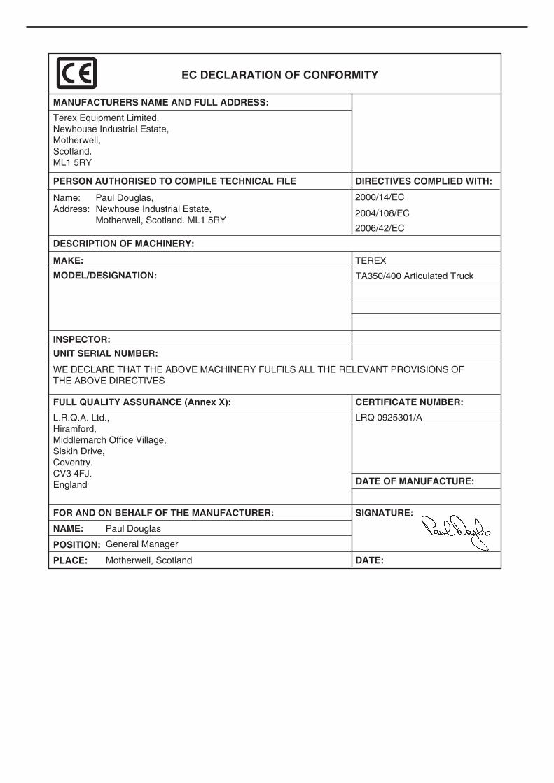
EC DECLARATION OF CONFORMITY
MANUFACTURERS NAME AND FULL ADDRESS:
Terex Equipment Limited,
Newhouse Industrial Estate,
Motherwell,
Scotland.
ML1 5RY
DESCRIPTION OF MACHINERY:
MAKE: TEREX
2000/14/EC
2004/108/EC
2006/42/EC
Name:
Address:
Paul Douglas,
Newhouse Industrial Estate,
Motherwell, Scotland. ML1 5RY
PERSON AUTHORISED TO COMPILE TECHNICAL FILE DIRECTIVES COMPLIED WITH:
MODEL/DESIGNATION:
UNIT SERIAL NUMBER:
INSPECTOR:
WE DECLARE THAT THE ABOVE MACHINERY FULFILS ALL THE RELEVANT PROVISIONS OF
THE ABOVE DIRECTIVES
FULL QUALITY ASSURANCE (Annex X):
L.R.Q.A. Ltd.,
Hiramford,
Middlemarch Office Village,
Siskin Drive,
Coventry.
CV3 4FJ.
England
NAME: Paul Douglas
General Manager
Motherwell, Scotland
POSITION:
PLACE:
CERTIFICATE NUMBER:
LRQ 0925301/A
FOR AND ON BEHALF OF THE MANUFACTURER:
DATE OF MANUFACTURE:
SIGNATURE:
DATE:
TA350/400 Articulated Truck
SPARE PARTS STATEMENT
When carrying out repairs, alterations or fitting attachments, it is important that only genuinespare parts are used to ensure the operating safety of the machine is not impaired.
It is only by using genuine parts that the technical requirements stipulated by the manufacturercan be maintained.
If a General Operating Approval is issued for this machine, it may be considered null and voidif non-genuine parts are used.

1-1
CONTENTS
1. INTRODUCTIONIntroduction 1-5Safety Alert Symbol 1-5Hazard Classification 1-5Intended Use of the Machine 1-6Product Identification No. 1-7Spare Parts Statement 1-7Theft Deterrent Practices 1-8
2. SAFETYGeneral 2-4Articulation and Oscillation Lock 2-5Vehicle Lifting Precautions 2-5Vehicle Tie Down Precautions 2-5Preventing Fire Hazards 2-6Mounting and Dismounting 2-7Pre-Starting 2-8Starting 2-8Operating 2-8Roading 2-10Lubrication and Servicing 2-10Scrapping the Machine 2-11Mirror and CCTV 2-12 Wheels and Tyres 2-14Avoid Tyre Explosion Hazard 2-15Emergency Exit from Cab 2-16Decals and Instruction Plates 2-17
3. CONTROLS AND OPERATINGControls and Instruments 3-3Fuse / Relay Box 3-4Basic Data 3-5Warning Lights 3-5Instruments 3-7Switches 3-9Controls 3-12Heater 3-13Air Conditioner 3-13Operator's Seat - Air Suspension 3-14Operator's Seat - Operation 3-15Seat Belt 3-17Machine Controls 3-18Braking 3-18Transmission Retarder 3-19Engine Brake 3-20Engine 3-21Electronic Foot Pedal 3-21Detroit Diesel Electronic Control 3-21Description 3-22Operation 3-23

1-2
This Page Intentionally Left Blank

1-3
3. CONTROLS AND OPERATING (cont.)Allison Series 4000 AutomaticShift Transmission 3-304th GEN Shift Controller 3-31Dropbox 3-37Differential Lock 3-37Hydraulic Controls 3-38Steering 3-39Body Control 3-40Tilting Cab 3-41Hood 3-42
4. OPERATING THE TRUCKPre-Starting Inspection 4-3Component Checks 4-3Engine Operation 4-6Starting the Engine 4-7Starting the Engine with Jumper Cables 4-9Pre-Operating Checks 4-10Brake Function Checks 4-11Driving and Stopping 4-12Stopping the Engine 4-14Parking 4-15
5. WORKING THE TRUCKWorking the Truck 5-3Loading 5-3Hauling 5-5Dumping 5-6Empty Return 5-7
6. ROADINGRoading 6-3General 6-3Preparation Prior to Roading 6-3In Case Of Trouble 6-4
7. MOVING DISABLED TRUCKMoving Disabled Truck 7-3
8. LUBRICATION AND SERVICINGSafety 8-3Lubrication and Servicing 8-4Lubrication and Service Chart 8-5Miscellaneous Servicing Information 8-7Recommended Lubricants 8-10
9. TECHNICAL DATATA350 9-3TA400 9-15
10. SYMBOL IDENTIFICATION

1-4
This Page Intentionally Left Blank
1-5
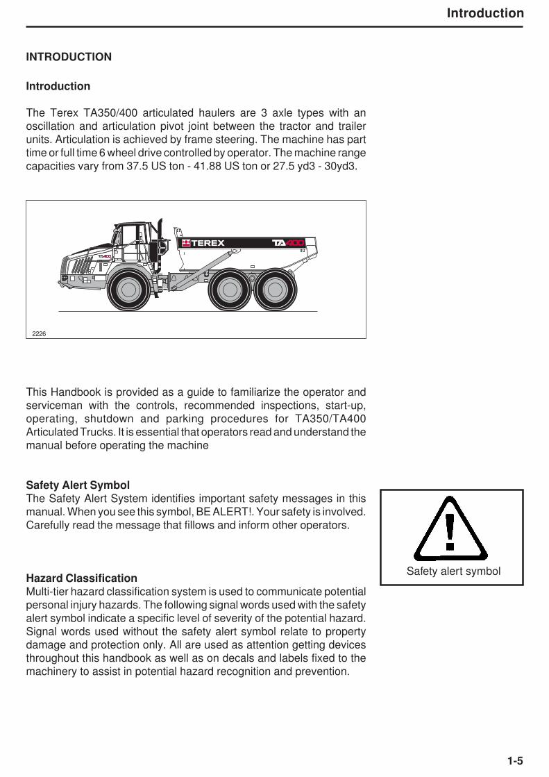
INTRODUCTION
Introduction
The Terex TA350/400 articulated haulers are 3 axle types with an
oscillation and articulation pivot joint between the tractor and trailer
units. Articulation is achieved by frame steering. The machine has part
time or full time 6 wheel drive controlled by operator. The machine range
capacities vary from 37.5 US ton - 41.88 US ton or 27.5 yd3 - 30yd3.
This Handbook is provided as a guide to familiarize the operator and
serviceman with the controls, recommended inspections, start-up,
operating, shutdown and parking procedures for TA350/TA400
Articulated Trucks. It is essential that operators read and understand the
manual before operating the machine
Safety Alert Symbol
The Safety Alert System identifies important safety messages in this
manual. When you see this symbol, BE ALERT!. Your safety is involved.
Carefully read the message that fillows and inform other operators.
Hazard ClassificationMulti-tier hazard classification system is used to communicate potential
personal injury hazards. The following signal words used with the safety
alert symbol indicate a specific level of severity of the potential hazard.
Signal words used without the safety alert symbol relate to property
damage and protection only. All are used as attention getting devices
throughout this handbook as well as on decals and labels fixed to the
machinery to assist in potential hazard recognition and prevention.
Introduction
Safety alert symbol
2226

1-6
Intended Use of MachineThis product and its approved attachments are designed to perform the followingfunctions.
1. Loading2. Hauling3. Dumping
Introduction
CAUTION used without the safety alert symbol indicates apotentially hazardous situation which, if not avoided, may result inproperty damage.
CAUTION
CAUTION
USE OTHER THAN INTENDED
Any use other than that stated in “Intended use” shall be consideredimpermissible.The manufacturer shall not be held liable for any resulting damage.The risk is borne by the user alone.
DANGER indicates an imminently hazardous situation which, ifnot avoided, will result in death or serious injury.
WARNING indicates a potentially hazardous situation which, ifnot avoided, could result in death or serious injury.
DANGER
WARNING
CAUTION indicates a potentially hazardous situation which,if not avoided, may result in minor or moderate injury.
1-7
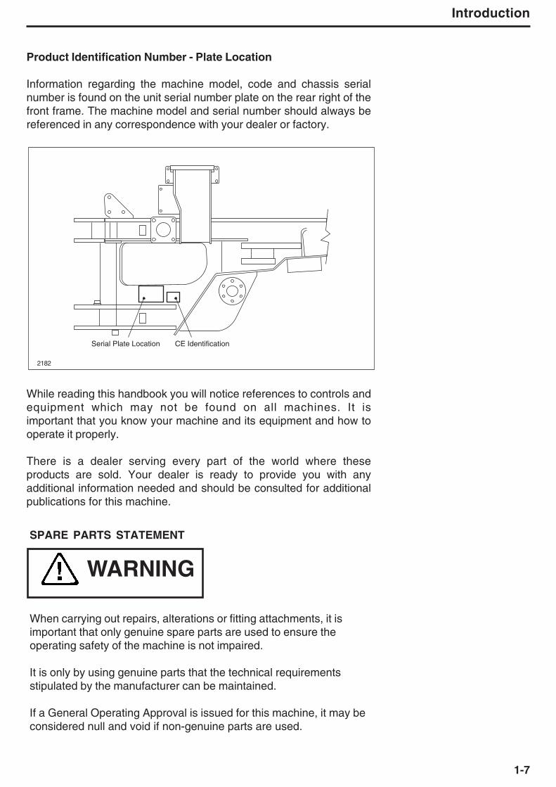
Product Identification Number - Plate Location
Information regarding the machine model, code and chassis serialnumber is found on the unit serial number plate on the rear right of thefront frame. The machine model and serial number should always bereferenced in any correspondence with your dealer or factory.
While reading this handbook you will notice references to controls andequipment which may not be found on all machines. It isimportant that you know your machine and its equipment and how tooperate it properly.
There is a dealer serving every part of the world where theseproducts are sold. Your dealer is ready to provide you with anyadditional information needed and should be consulted for additionalpublications for this machine.
Introduction
SPARE PARTS STATEMENT
When carrying out repairs, alterations or fitting attachments, it isimportant that only genuine spare parts are used to ensure theoperating safety of the machine is not impaired.
It is only by using genuine parts that the technical requirementsstipulated by the manufacturer can be maintained.
If a General Operating Approval is issued for this machine, it may beconsidered null and void if non-genuine parts are used.
WARNING
Serial Plate Location CE Identification
2182

1-8
Theft Deterrent Practices
GeneralThe owner/operator should take the following precautions todiscourage theft, to aid in the recovery in the event that the machine isstolen, or to reduce vandalism.
Actions to Discourage Theft and VandalismRemove all keys any time the machine is left unattended.
At night lock all doors and attach, secure or lock all anti-vandalism andanti-theft devices on the machine.
Immobilize the machine by removing a critical electrical or startingsystem device, for example Fuse 31 or 32.
Upon receipt of a machine, record the machine serial number and theserial numbers of all major components and attachments. Keep this listup to date and filed in a safe location for fast retrieval.Place a decal or notice on the machine that all serial numbers arerecorded.
Discourage the thief! Inspect the gates and fences of the machinerystorage yard or construction site. Keep machines in well-lit areas andask the local law enforcement authorities to make frequent checksaround the storage yard or work site.
Establish liaison with neighbours and ask them to watch equipment leftat job sites and to report any suspicious activities to the local lawenforcement authorities.
Make frequent inventories of machines to promptly detect losses orvandalism.
Actions to Aid in Recovery of Stolen MachinesIn the event of theft, immediately notify the law enforcement authoritieshaving jurisdiction. Provide the investigating officer with name, type ofequipment, chassis and serial numbers of major attachments andcomponents. It is helpful to show the investigating officer an Operator’sHandbook, photographs, and advertising, to familiarize him with theappearance of the machine.
Report the theft to the insurance company. Provide the model and allserial numbers.
Report the model and serial numbers of the stolen machine to a dealerhandling the respective line of equipment. Request that the dealerforward this same information to the equipment manufacturer.

2-1
Safety
2 - Safety

2-2
Safety
This Page Intentionally Left Blank

2-3
Safety
SAFETY
Safety
The machine should be properly operated and maintained to keep it in
safe, efficient operating condition. Be sure that all controls are free of
mud, grease, or other matter that might cause slips hazardous to the
operator, serviceman, or other personnel or equipment. Report all
malfunctions to those responsible for maintenance, and, do not
operate the equipment until corrected. Normal service or
maintenance performed as required can prevent unexpected and
unnecessary downtime.
This Handbook describes general inspections, servicing and
operation with the normal safety precautions required for normal
servicing and operating conditions. It is not a guide however, for other
than normal conditions or situations, and therefore, servicemen and
operators must be safety conscious and alert to recognize potential
servicing or operating safety hazards at all times, and take necessary
precautions to assure safe servicing and operation of the machine.
These machines are equipped with cylinders containingcompressed nitrogen gas. Transportation of these machinesby any method may require a special permit from theappropriate authority of the country involved. Consult yourdealer for details.
All information, illustrations and specifications contained in this
publication are based on the latest product information available at the
time of publication. The right is reserved to make changes at any time
without notice.
Continuing improvement and advancement of the design may cause
changes to your machine which may not be included in this publication.
Each publication is reviewed and revised, as required, to update and
include these changes in later editions.
This Handbook contains lubrication and routine servicing instructions,
most of which can be performed in the field. Maintenance manuals
containing repair/rebuild procedures can be obtained from your dealer.

2-4
Safety
SAFETY PRECAUTIONS
General
* Read this Operator’s Handbook and learn the operatingcharacteristics and limitations of the vehicle. Know whatoperating clearances the vehicle requires.
• Read and understand all the safety signs prior to operation.
• If the safety signs are obstructed by dirt or debris, clean themusing mild soap and water prior to operation.
• If the safety signs are damaged or illegible, replace themimmediately, prior to operation.
* Read the AEM Safety Manual and follow the recommendedsafety precautions.
* Know clearances of all side and overhead obstructions suchas wires, bridges, etc., for operating safely.
* Be especially aware of overhead power lines.
* Always know all traffic rules, signs, flags and hand signals used onthe job and know who has the responsibility forsignalling.
* Be aware of operating hazards that weather changes cancreate on the job. Know proper procedures to follow when asevere rain or electrical storm strikes.
* Never attempt to operate or work on a vehicle when not feelingphysically fit.
* Know what safety equipment is required and use it. Suchequipment may be: Hard hat, safety glasses, reflector typevests, respirators, safety shoes and ear plugs.
* Never wear loose clothing, rings, watches etc., that might catchlevers and controls and cause loss of control.
* Keep hands and controls free from water, grease and mud toassure nonslip control.
* Handle fuels and lubricants carefully and clean up spills toavoid fire and slipping hazards.
* Clean any mud, grease or oil from controls, handrails, laddersand decks. Lash necessary tools securely and remove allloose items before operating the vehicle. Never rush. Walk, donot run.
* Never carry more than one person and only in the instructor/trainerseat.
1782
1768
SAFETY
MANUAL
1767
1769
2-5
Safety
The protection offered by the roll over and falling object
protective structure may be impaired if it has been subjected
to any modification or damage. Unauthorized modification
will void certification.
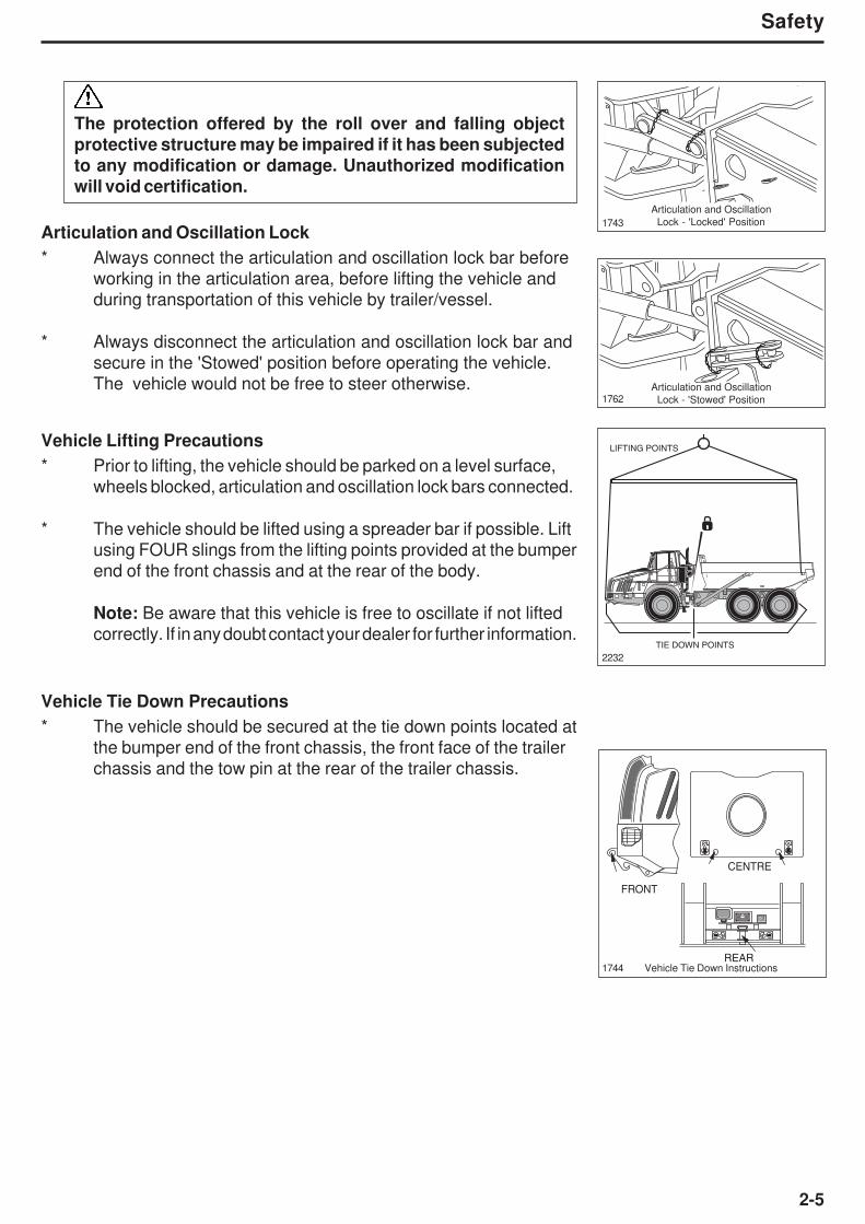
Articulation and Oscillation Lock
* Always connect the articulation and oscillation lock bar before
working in the articulation area, before lifting the vehicle and
during transportation of this vehicle by trailer/vessel.
* Always disconnect the articulation and oscillation lock bar and
secure in the 'Stowed' position before operating the vehicle.
The vehicle would not be free to steer otherwise.
Articulation and Oscillation
Lock - 'Locked' Position1743
Articulation and Oscillation
Lock - 'Stowed' Position1762
Vehicle Lifting Precautions
* Prior to lifting, the vehicle should be parked on a level surface,
wheels blocked, articulation and oscillation lock bars connected.
* The vehicle should be lifted using a spreader bar if possible. Lift
using FOUR slings from the lifting points provided at the bumper
end of the front chassis and at the rear of the body.
Note: Be aware that this vehicle is free to oscillate if not lifted
correctly. If in any doubt contact your dealer for further information.
Vehicle Tie Down Precautions
* The vehicle should be secured at the tie down points located at
the bumper end of the front chassis, the front face of the trailer
chassis and the tow pin at the rear of the trailer chassis.
2232
CENTRE
FRONT
REARVehicle Tie Down Instructions1744
TIE DOWN POINTS
LIFTING POINTS
2-6
Safety
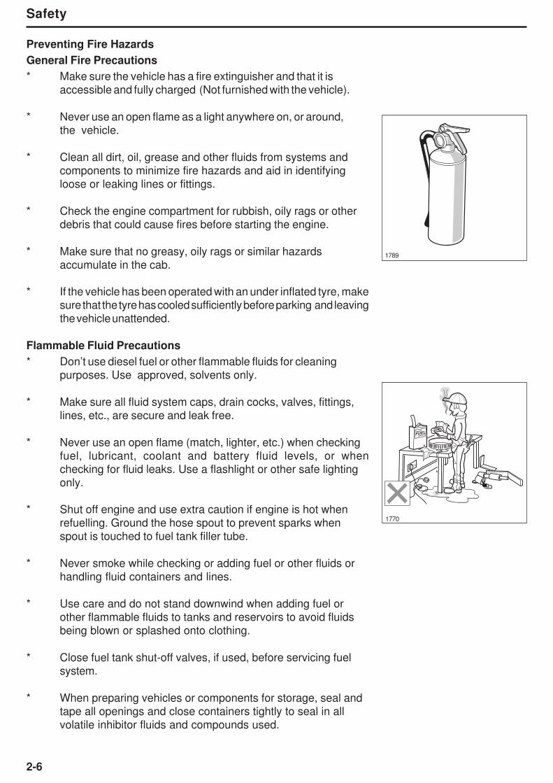
Preventing Fire Hazards
General Fire Precautions
* Make sure the vehicle has a fire extinguisher and that it is
accessible and fully charged (Not furnished with the vehicle).
* Never use an open flame as a light anywhere on, or around,
the vehicle.
* Clean all dirt, oil, grease and other fluids from systems and
components to minimize fire hazards and aid in identifying
loose or leaking lines or fittings.
* Check the engine compartment for rubbish, oily rags or other
debris that could cause fires before starting the engine.
* Make sure that no greasy, oily rags or similar hazards
accumulate in the cab.
* If the vehicle has been operated with an under inflated tyre, make
sure that the tyre has cooled sufficiently before parking and leaving
the vehicle unattended.
Flammable Fluid Precautions
* Don’t use diesel fuel or other flammable fluids for cleaning
purposes. Use approved, solvents only.
* Make sure all fluid system caps, drain cocks, valves, fittings,
lines, etc., are secure and leak free.
* Never use an open flame (match, lighter, etc.) when checking
fuel, lubricant, coolant and battery fluid levels, or when
checking for fluid leaks. Use a flashlight or other safe lighting
only.
* Shut off engine and use extra caution if engine is hot when
refuelling. Ground the hose spout to prevent sparks when
spout is touched to fuel tank filler tube.
* Never smoke while checking or adding fuel or other fluids or
handling fluid containers and lines.
* Use care and do not stand downwind when adding fuel or
other flammable fluids to tanks and reservoirs to avoid fluids
being blown or splashed onto clothing.
* Close fuel tank shut-off valves, if used, before servicing fuel
system.
* When preparing vehicles or components for storage, seal and
tape all openings and close containers tightly to seal in all
volatile inhibitor fluids and compounds used.
FUEL
1770
1789

2-7
Safety
* Follow manufacturer’s recommendations when handling and
using engine-starting fluids and disposing of spent containers.
Do not puncture or burn empty containers. These fluids are
explosive and highly flammable.
Electrical Hazard Precautions
* Never smoke or allow open flames or sparks near batteries.
* Leave battery box open when charging batteries in the vehicle
for adequate ventilation of explosive gas (hydrogen) produced.
* Always disconnect batteries before repairing electrical system to
avoid danger of fire-causing sparks. Disconnect the battery
ground cable first and reconnect it last.
* Always disconnect batteries, alternator leads, engine ECM,
hydraulic system ECU, body control lever, transmission ECU,
instrument panel ECU and all harness connections at the front
of the cab before carrying out any welding on the vehicle.
* Never check the battery charge by placing metal objects across
the battery posts, to avoid sparks at battery posts.
* Use jumper cables only as recommended. Improper use can
result in battery explosion or unexpected vehicle motion.
* Never operate the engine starter for more than 30 seconds, and
allow two minutes between long cranking periods for cooling.
An overheated starter could cause a fire.
* If electric coolant or lubricant heaters are used, be sure to follow
heater manufacturer’s recommendations for use to avoid
electrical or fire hazards or both.
Mounting and Dismounting
* Only use steps and hand holds provided to mount or dismount
the vehicle. Do not grasp the steering wheel.
* Always face the access system and maintain at least three
points of support to mount or dismount the vehicle (two hands and
one foot, or two feet and one hand.
* Ensure walkways, stairways, platforms, handrails and handholds
are free of frost, ice, oil, water or anything else that could cause slip,
trip or falls.
* Never mount or dismount a moving vehicle. Never jump off the
vehicle.
1771
1772

2-8
Safety
Pre-Starting
* If engine is to be started and run indoors, ensure proper
ventilation to remove deadly exhaust gases.
* Always perform 'Pre-Starting Inspection' instructions described
on page 4-3 to ensure the vehicle is ready for operation.
* Always walk around the vehicle to make sure no-one is working
on, underneath or close to the vehicle before starting the engine
or operating the vehicle.
* Adjust, secure and latch the seat and fasten the seat belt before
starting the vehicle.
* Sound horn before starting the engine or beginning to move the
vehicle; two blasts for forward and three blasts for reverse.
Starting
* Do not start the engine or operate any control if there is a 'DO
NOT OPERATE' or similar warning sign attached to any control.
* Use jumper cables only as recommended. Improper use can
result in battery explosion or unexpected vehicle motion.
* Always obey 'Starting the Engine' instructions described on
page 4-7.
* Do not bypass the vehicle’s neutral-start system. The neutral-
start system must be repaired if it malfunctions.
* Start and operate the vehicle only from the operator’s seat.
Operating
* Ensure all cab glass, mirrors and light lenses are clean during
vehicle operation for maximum visibility. Ensure mirrors are
properly set / positioned.
* Always keep cab floor clear of anything that could restrict full
operation of pedals.
* Always make sure all gauges, warning/indicator lights and
controls are working properly before operating the vehicle.
* Always perform 'Pre-Operating Checks' described on page 4-10
to ensure the vehicle is ready for operating.
* Always wear seat belts when operating the vehicle.
* Do not operate if exposed personnel enter the immediate work
area.
* Sound horn before starting engine or beginning to move the
vehicle; two blasts for forward and three blasts for reverse.
1773
DO NOT
OPERATE
1775
1790
1776
P
STOP
1
2
10
10
20
30
40 50
60
70
80
km/h
2030
40
mph
50
30
0
0
5
r / min x100
10
20
25
15
˚F
LH
2-9
Safety
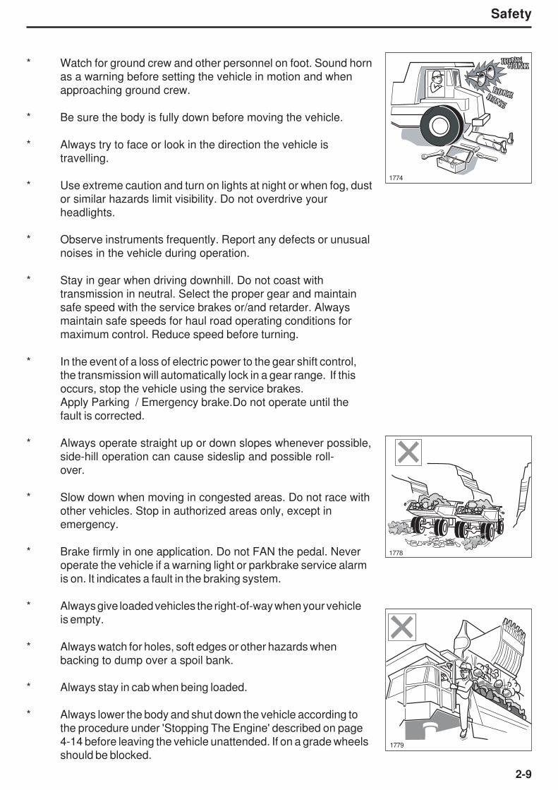
* Watch for ground crew and other personnel on foot. Sound horn
as a warning before setting the vehicle in motion and when
approaching ground crew.
* Be sure the body is fully down before moving the vehicle.
* Always try to face or look in the direction the vehicle is
travelling.
* Use extreme caution and turn on lights at night or when fog, dust
or similar hazards limit visibility. Do not overdrive your
headlights.
* Observe instruments frequently. Report any defects or unusual
noises in the vehicle during operation.
* Stay in gear when driving downhill. Do not coast with
transmission in neutral. Select the proper gear and maintain
safe speed with the service brakes or/and retarder. Always
maintain safe speeds for haul road operating conditions for
maximum control. Reduce speed before turning.
* In the event of a loss of electric power to the gear shift control,
the transmission will automatically lock in a gear range. If this
occurs, stop the vehicle using the service brakes.
Apply Parking / Emergency brake.Do not operate until the
fault is corrected.
* Always operate straight up or down slopes whenever possible,
side-hill operation can cause sideslip and possible roll-
over.
* Slow down when moving in congested areas. Do not race with
other vehicles. Stop in authorized areas only, except in
emergency.
* Brake firmly in one application. Do not FAN the pedal. Never
operate the vehicle if a warning light or parkbrake service alarm
is on. It indicates a fault in the braking system.
* Always give loaded vehicles the right-of-way when your vehicle
is empty.
* Always watch for holes, soft edges or other hazards when
backing to dump over a spoil bank.
* Always stay in cab when being loaded.
* Always lower the body and shut down the vehicle according to
the procedure under 'Stopping The Engine' described on page
4-14 before leaving the vehicle unattended. If on a grade wheels
should be blocked.1779
1778
1774

2-10
Safety
Roading
* Match speed to road conditions.
* Yield the right of way when required. Obey the rules of the road.
* Stay as close to the side of the road as possible. Pass other
equipment only when the road is clear and enough room / space
to pass and reserve power is available.
* Stop at appropriate intervals to inspect the vehicle and allow the
tyres to cool. Tyre air pressure will rise during operation. Do not
reduce tyre pressure. Excess speed will cause tyres to heat up.
Reduce your travel speed, not tyre pressure.
* Use accessory lights and devices at night or in poor visibility.
Carry a flare kit. Do not overdrive your headlights.
Lubrication and Servicing
* Do not allow unauthorized personnel to service or maintain
this vehicle. Study this Operator’s Handbook and the
Maintenance Manual before starting, operating or servicing
this vehicle. Always follow procedures and safety precautions
detailed throughout the Maintenance Manual.
* Always attach a 'DO NOT OPERATE' or similar warning sign to
the ignition switch or a prominent control before cleaning,
lubricating or servicing the vehicle.
* Never allow anyone to work on the vehicle while it is moving.
Make sure there is no one on the vehicle before working on it.
* Do not work under or near an unblocked or unsupported body.
Always use the body safety prop. The body safety prop must
only be used when the body is empty.
* Do not work under or near any unblocked or unsupported
linkage, part or vehicle.
* Always install the steering lock bar before making adjustments
or servicing the vehicle with the engine running. Refer to
'General' safety section.
* Always shut down the vehicle according to the procedure under
'Stopping The Engine', described on page 4-14, and turn off the
master switch before cleaning, lubricating or servicing the
vehicle except as called for in this Operator’s Handbook or the
Maintenance Manual.
Body Safety Prop1794
1780
1777

2-11
Safety
* Always relieve pressure before servicing any pressurised
system. Follow the procedures and safety precautions detailed
in the relevant Maintenance Manual section.
* When changing oil in the engine, transmission and hydraulic
systems, or removing hydraulic lines, remember that the oil may
be hot and can cause burns to unprotected skin.
* When working on or around exhaust components, remember
that the components may be hot and can cause burns to
unprotected skin.
* Always deflate the tyre before attempting to remove any
embedded objects or removing the tyre and rim assembly from
the vehicle.
* Always use a self-attaching chuck with a long airline, and, stand
to one side while the tyre is inflating. Refer to Section 160-0050,
WHEEL RIM AND TYRE in the Maintenance Manual.
* Do not work under or near an unblocked or unsupported raised
operator’s cab. Always use the operator’s cab safety prop with
the locking pin.
Scrapping the Machine
At the end of its life, the machine should be disassembled by a
competent person using safe working practices, wearing the
appropriate Personal Protective Equipment and working in accordance
with local regulations.
The appropriate lifting equipment, chocks and stands must be used
to maintain a stable machine as components are removed and the
machines centre of mass changes. Fluids must be drained off into
suitable containers and if possible recycled or otherwise disposed of
an environmentally friendly in accordance with local regulations.
Care must be taken when dealing with flammable liquids and the
machine parts that contained those liquids. Any process that could
ignite flammable materials must not be used on components that
have contained flammable liquids in them or have residual flammable
liquids on them.
Fire extinguishers must be readily available if cutting/welding
equipment is to be used.
When possible recyclable materials should be separated out and
processed in accordance with local regulations using an authorised
agent.
1993
Operators Cab Safety Prop & Locking Pin
With Cab Raised
1727 Operators Cab safety Prop

2-12
Safety
Mirrors and CCTV
The operator must survey their surroundings before entering the machine, and
check their field of vision prior to and during operation of the machine. All
mirrors must be adjusted when installed, and prior to operating the machine, to
achieve optimum visibility and thus minimize the risk of injury to themself and
others. Site management should utilize appropriate jobsite organization to
minimize hazards due to restricted visibility. Modifications made to the machine
may restrict the visibility and compromise compliance with safety standards
(ISO 5006:2006).
Make sure that all mirrors are installed and adjusted to optimize operator visibility. The mirrors,
illustrated below, are all capable of adjustment. Make sure that the brackets which support these
mirrors are folded out from the cab to form an angle of 90O . These brackets may be folded parallel
to the cab for transportation of the vehicle. Set the mirrors in the defined position shown in the
illustration.
2118
2115
A B C D
140
120
190
155
2-13
Safety
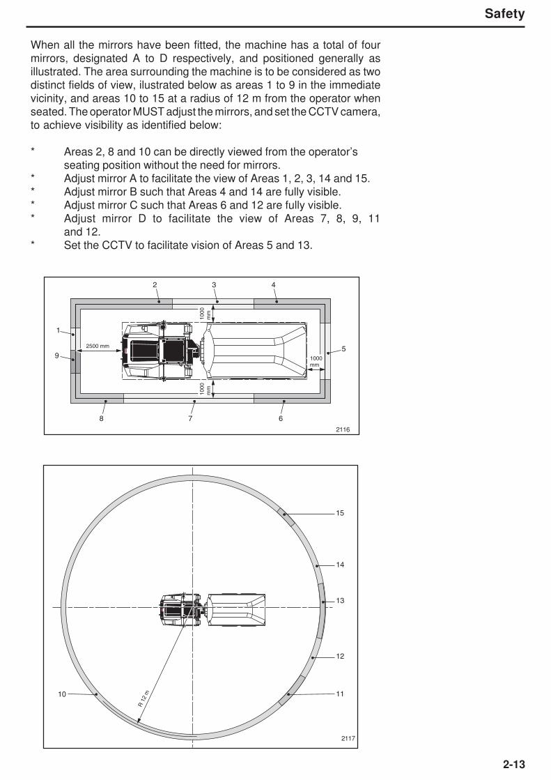
When all the mirrors have been fitted, the machine has a total of four
mirrors, designated A to D respectively, and positioned generally as
illustrated. The area surrounding the machine is to be considered as two
distinct fields of view, ilustrated below as areas 1 to 9 in the immediate
vicinity, and areas 10 to 15 at a radius of 12 m from the operator when
seated. The operator MUST adjust the mirrors, and set the CCTV camera,
to achieve visibility as identified below:
* Areas 2, 8 and 10 can be directly viewed from the operator’s
seating position without the need for mirrors.
* Adjust mirror A to facilitate the view of Areas 1, 2, 3, 14 and 15.
* Adjust mirror B such that Areas 4 and 14 are fully visible.
* Adjust mirror C such that Areas 6 and 12 are fully visible.
* Adjust mirror D to facilitate the view of Areas 7, 8, 9, 11
and 12.
* Set the CCTV to facilitate vision of Areas 5 and 13.
2117
2116
2500 mm
1000
mm
1000
mm
1000mm
1
59
8 6
2 43
7
15
14
1110
13
12
R 1
2 m
2-14
Safety
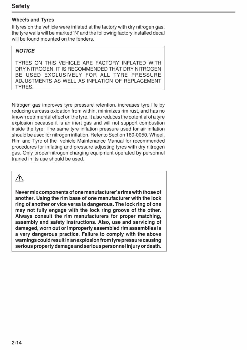
Wheels and Tyres
If tyres on the vehicle were inflated at the factory with dry nitrogen gas,
the tyre walls will be marked 'N' and the following factory installed decal
will be found mounted on the fenders.
NOTICE
TYRES ON THIS VEHICLE ARE FACTORY INFLATED WITH
DRY NITROGEN. IT IS RECOMMENDED THAT DRY NITROGEN
BE USED EXCLUSIVELY FOR ALL TYRE PRESSURE
ADJUSTMENTS AS WELL AS INFLATION OF REPLACEMENT
TYRES.
Nitrogen gas improves tyre pressure retention, increases tyre life by
reducing carcass oxidation from within, minimizes rim rust, and has no
known detrimental effect on the tyre. It also reduces the potential of a tyre
explosion because it is an inert gas and will not support combustion
inside the tyre. The same tyre inflation pressure used for air inflation
should be used for nitrogen inflation. Refer to Section 160-0050, Wheel,
Rim and Tyre of the vehicle Maintenance Manual for recommended
procedures for inflating and pressure adjusting tyres with dry nitrogen
gas. Only proper nitrogen charging equipment operated by personnel
trained in its use should be used.
Never mix components of one manufacturer’s rims with those ofanother. Using the rim base of one manufacturer with the lockring of another or vice versa is dangerous. The lock ring of onemay not fully engage with the lock ring groove of the other.Always consult the rim manufacturers for proper matching,
assembly and safety instructions. Also, use and servicing of
damaged, worn out or improperly assembled rim assemblies isa very dangerous practice. Failure to comply with the abovewarnings could result in an explosion from tyre pressure causing
serious property damage and serious personnel injury or death.

2-15
Safety
Avoid Tyre Explosion Hazard
Whenever a vehicle’s tyre(s) is (are) exposed to
excessive heat such as a vehicle fire or extremely
hot brakes, the hazard of a subsequent violent
tyre explosion must be recognized. All nearby
persons must avoid approaching the vehicle so
as not to be physically endangered in the event
of an explosion of the tyre and rim parts. The
vehicle should be moved to a remote area, but
only when this can be done with complete safety
of the operator operating or towing the vehicle.
All other persons should stay clear of the vehicle.
The fire or overheated brakes, wheel, etc., should
be extinguished or cooled from a safe distance.
Do not attempt to extinguish the fire or cool the
vehicle by use of hand-held fire extinguishers. Ifit is absolutely necessary to approach a vehiclewith a suspect tyre, approach only from the frontor the back. Stay at least 15 m (50 ft) from the treadarea. Keep observers out of the area and at least460 m (1500 ft) from the tyre sidewall. Refer to theaccompanying sketch. The tyre(s) should beallowed at least eight (8) hours cooling time afterthe vehicle is shut down or the fire extinguishedbefore approaching closer.
AT LEAST
15m (50ft)
AT LEAST
460m (1 500ft)
172

2-16
Safety
Emergency Exit from Cab
Normal access to, and egress from, the cab is facilitated
via the door on the left-hand side. However, in an
emergency, an alternative exit can be gained via the
side windows. A hammer is provided to break the left-
hand or right-hand side window glass to facilitate safe
egress.
The hammer is mounted on a bracket on the rear wall
of the cab, and can be easily lifted off in an emergency.
2082
Do not attempt to break the windscreenwith the Emergency hammer. It is ONLYprovided to allow access through the left-hand and right-hand windows.
Exercise extreme care when breaking thewindow glass to protect your face andbody from airborne glass particles.
Be careful when passing through thewindow aperture to avoid contact with
shards of glass that may remain attachedto the frame, or loose within or outside ofthe cab.
2-17
Safety
2227
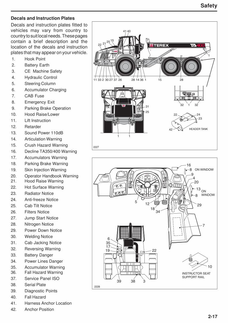
Decals and Instruction Plates
Decals and instruction plates fitted to
vehicles may vary from country to
country to suit local needs. These pages
contain a brief description and the
location of the decals and instruction
plates that may appear on your vehicle.
1. Hook Point
2. Battery Earth
3. CE Machine Safety
4. Hydraulic Control
5. Steering Column
6. Accumulator Charging
7. CAB Fuse
8. Emergency Exit
9. Parking Brake Operation
10. Hood Raise/Lower
11. Lift Instruction
12. Retarder
13. Sound Power 110dB
14. Articulation Warning
15. Crush Hazard Warning
16. Decline TA350/400 Warning
17. Accumulators Warning
18. Parking Brake Warning
19. Skin Injection Warning
20. Operator Handbook Warning
21. Hood Raise Warning
22. Hot Surface Warning
23. Radiator Notice
24. Anti-freeze Notice
25. Cab Tilt Notice
26. Filters Notice
27. Jump Start Notice
28. Nitrogen Notice
29. Power Down Notice
30. Welding Notice
31. Cab Jacking Notice
32. Reversing Warning
33. Battery Danger
34. Power Lines Danger
35. Accumulator Warning
36. Fall Hazard Warning
37. Service Panel ISO
38. Serial Plate
39. Diagnostic Points
40. Fall Hazard
41. Harness Anchor Location
42. Anchor Position
2228
11 33 2 30 27 37 26 28 14 36 1 15 28
22 212515
41 40
1
1 3232
24
23
22
42
31
25
1 1
HEADER TANK
PSTOP
1
2
10
10
20
3040
50
60
70
80
km/h
20 30
40mph
50 300 0
5r / min x100
10 20
25
15
4070
100
150105
210
250
120 60
140
275 320390
135 165
200
˚C
˚F
˚C
˚F
L H
INSTRUCTOR SEAT
SUPPORT RAIL
10
ON
WINDOW
7
9
12
16
420
29
13
8
ON WINDOW8
1834
5
6
1735
19 22
33839

2-18
Safety
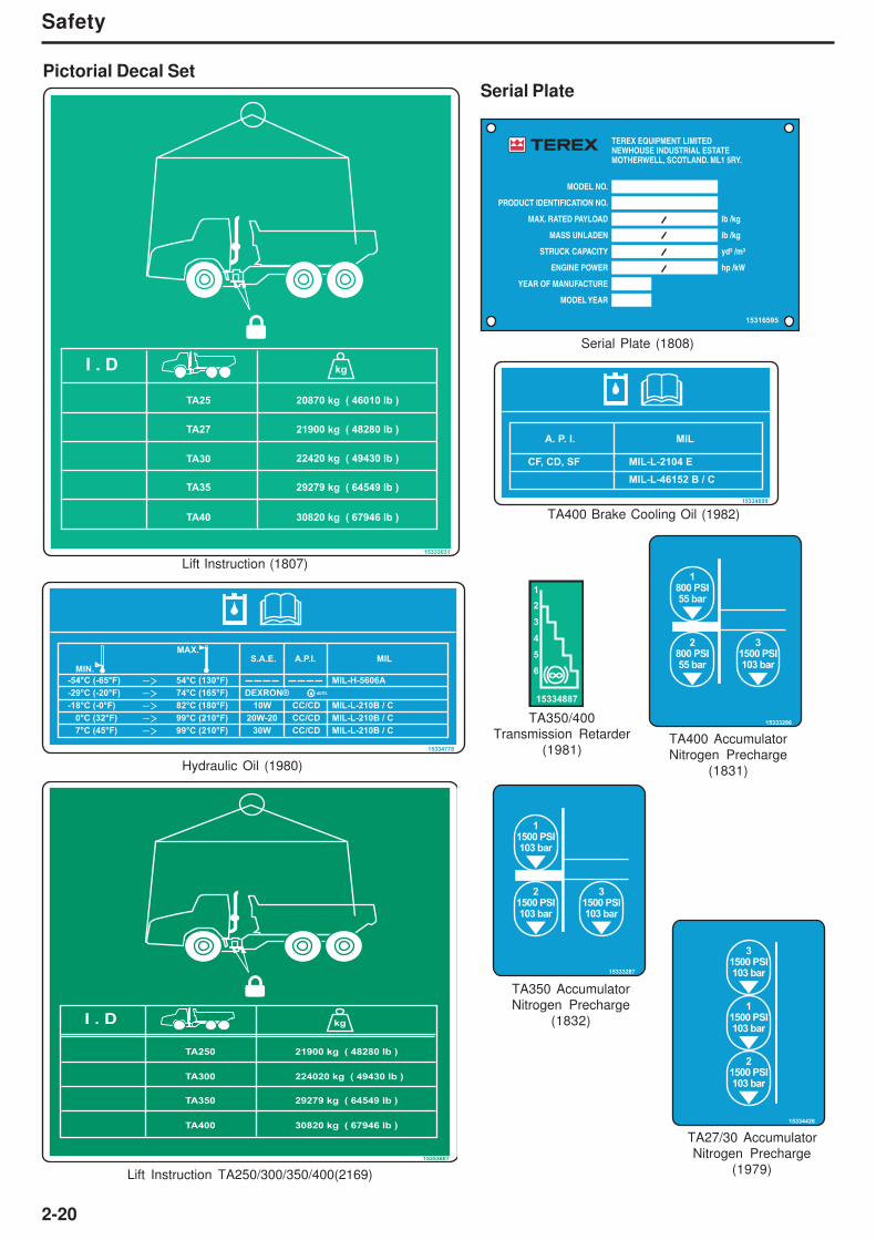
Pictorial Decal Set
9271069
Hook Point (1797)
9361787
Battery Earth (1798)CE Marking (1799)
15314811
Body Control (1800)
15318464
Steering Column
Adjustment (1801)
15321634
Emergency Exit (1804)
15321636
1
2
Hood Catch (1837)
15321641
P
P
Park Brake (1805)
Transmission Filter (2189)
15331997
WA
Sound Power (1976)
15331998
WA
Sound Power (1977)
15332624
WA
Sound Power (1809)
15332852
Hood Raise Lower
(1806)
15314033
WA
Sound Power (1975)
TA25 / 27 / 30TA25 / 27 / 30
TEREX : 15273572ZF : O750 131 061
TEREX : 15271723ZF : O750 131 063
15336110
F
R
P
TA27/30 Diagnostic Point (2190)
15356709
15356570
Fall Hazard (2221)Safety Harness (2222)

2-19
Safety
Pictorial Decal Set
15354737
P
NN
NN
K23
AUX SUPPLIES
HYDECU
HYDECU
R
R
TV
K17 K50 K32
K23 K14 K23
K33
K52
K34 K27
K15
K58
K57 K4 K23
F12
(7.5A)
F24
(10A)
F36
(15A)
F11
(10A)
F23
(3A)
F35
(5A)
F10
(15A)
F22
(3A)
F34
(3A)
F9
(7.5A)
F21
(3A)
F33
(10A)
F8
(10A)
F20
(15A)
F32
(30A)
F7
(10A)
F19
(3A)
F31
(5A)
F6
(10A)
F18
(15A)
F30
(5A)
F5
(10A)
F17
(7.5A)
F29
(15A)
F4
(10A)
F16
(3A)
F28
(15A)
F3
(7.5A)
F15
(5A)
F27
(10A)
F2
(15A)
F14
(5A)
F26
(15A)
F1
(20A)
F13
(30A)
F25
(30A)
12V
24V
12V
24V
F'L'
(10A)
F'K'
(20A)
F'A'
(5A)
F'M'
(15A)
1/R
K71
P
TA250/300 Fuse Relay Box (2223)
TA350/400 Fuse Relay Box (2224)
15354606
P
NN
NN
K23
AUX SUPPLIES
HYDECU
HYDECU
R
R
TV
K17 K50 K32
K23 K14 K23 K52
K34 K71 K27 K64
K15
K48
K68
K69
K25 K63 K4 K23
F12
(7.5A)
F24
(10A)
F36
(15A)
F11
(10A)
F23
(3A)
F35
(5A)
F10
(15A)
F22
(3A)
F34
(15A)
F9
(7.5A)
F21
(3A)
F33
(10A)
F8
(10A)
F20
(15A)
F32
(30A)
F7
(10A)
F19
(3A)
F31
(10A)
F6
(10A)
F18
(15A)
F30
(5A)
F5
(10A)
F17
(7.5A)
F29
(15A)
F4
(10A)
F16
(3A)
F28
(15A)
F3
(7.5A)
F15
(5A)
F27
(10A)
F2
(15A)
F14
(5A)
F26
(15A)
F1
(20A)
F13
(30A)
F25
(30A)
H
L
H
L
H
L
12V
24V
24V
F'L'
(15A)
F'J'
(5A)
24V
F'K'
(20A)
F'M'
(10A)
K66
K67
H
L
P
AUTO
r/min
H
L
K72
P
15333633
P
NN
NN
K23
AUX SUPPLIES
HYDECU
HYDECU
R
R
TV
K17 K50 K32
K23 K14 K23 K52
K34 K27K5
K15
K58
K57 K4 K23
F12
(7.5A)
F24
(10A)
F36
(15A)
F11
(10A)
F23
(3A)
F35
(5A)
F10
(15A)
F22
(3A)
F34
(3A)
F9
(7.5A)
F21
(3A)
F33
(10A)
F8
(10A)
F20
(15A)
F32
(30A)
F7
(10A)
F19
(3A)
F31
(10A)
F6
(10A)
F18
(15A)
F30
(5A)
F5
(10A)
F17
(7.5A)
F29
(15A)
F4
(10A)
F16
(3A)
F28
(15A)
F3
(7.5A)
F15
(5A)
F27
(10A)
F2
(15A)
F14
(5A)
F26
(15A)
F1
(20A)
F13
(30A)
F25
(30A)
H
L
12V
24V
12V
24V
F'L'
(15A)
F'K'
(20A)
F'M'
(10A)
1/R
TA27/30 Fuse Relay Box (1978)
15333012
P
NN
NN
K23
AUX SUPPLIES
HYDECU
HYDECU
R
R
TV
K17 K50 K32
K23 K14 K23 K52
K34 K65 K27 K64
K15
K48
K25 K63 K4 K23
F12
(7.5A)
F24
(10A)
F36
(15A)
F11
(10A)
F23
(3A)
F35
(5A)
F10
(15A)
F22
(3A)
F34
(15A)
F9
(7.5A)
F21
(3A)
F33
(10A)
F8
(10A)
F20
(15A)
F32
(30A)
F7
(10A)
F19
(3A)
F31
(10A)
F6
(10A)
F18
(15A)
F30
(5A)
F5
(10A)
F17
(7.5A)
F29
(15A)
F4
(10A)
F16
(3A)
F28
(15A)
F3
(7.5A)
F15
(5A)
F27
(10A)
F2
(15A)
F14
(5A)
F26
(15A)
F1
(20A)
F13
(30A)
F25
(30A)
H
L
H
L
H
L
H
L
12V
24V
24V
24V
F'M'
(15A)
F'K'
(20A)
F'L'
(10A)
K66
TA35/40 Fuse Relay Box (1803)
2-20
Safety
Pictorial Decal Set
MIL-L-2104 ECF, CD, SF
MILA. P. I.
MIL-L-46152 B / C
15334899
TA400 Brake Cooling Oil (1982)
Serial Plate
15316595
TEREX EQUIPMENT LIMITEDNEWHOUSE INDUSTRIAL ESTATEMOTHERWELL, SCOTLAND. ML1 5RY.
MODEL NO.
PRODUCT IDENTIFICATION NO.
MAX. RATED PAYLOAD
MASS UNLADEN
STRUCK CAPACITY
ENGINE POWER
lb /kg
lb /kg
yd³ /m³
hp /kW
YEAR OF MANUFACTURE
MODEL YEAR
Serial Plate (1808)
15333286
1800 PSI55 bar
2800 PSI55 bar
31500 PSI103 bar
TA400 Accumulator
Nitrogen Precharge
(1831)
15333287
11500 PSI103 bar
21500 PSI103 bar
31500 PSI103 bar
TA350 Accumulator
Nitrogen Precharge
(1832)
15334426
11500 PSI103 bar
31500 PSI103 bar
21500 PSI103 bar
TA27/30 Accumulator
Nitrogen Precharge
(1979)
15334887
1
2
3
4
5
6
TA350/400
Transmission Retarder
(1981)
15353607
I . D kg
TA250
TA300
21900 kg ( 48280 lb )
224020 kg ( 49430 lb )
TA350
TA400
29279 kg ( 64549 lb )
30820 kg ( 67946 lb )
15333031
I . D kg
TA25
TA27
TA30
TA35
TA40
20870 kg ( 46010 lb )
21900 kg ( 48280 lb )
22420 kg ( 49430 lb )
29279 kg ( 64549 lb )
30820 kg ( 67946 lb )
Lift Instruction TA250/300/350/400(2169)
MIN.
MAX.
-54°C (-65°F) 54°C (130°F)
-29°C (-20°F) 74°C (165°F)
-18°C (-0°F) 82°C (180°F)
0°C (32°F) 99°C (210°F)
7°C (45°F) 99°C (210°F)
DEXRON®
10W
20W-20
30W
MIL-H-5606A
MILA.P.I.S.A.E.
MIL-L-210B / C
MIL-L-210B / C
MIL-L-210B / C
CC/CD
CC/CD
CC/CD
AUTO.
15334778
Hydraulic Oil (1980)
Lift Instruction (1807)
2-21
Safety
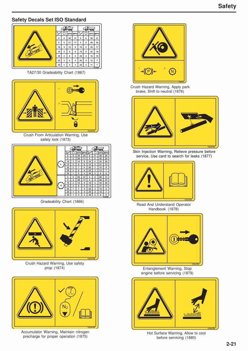
Safety Decals Set ISO Standard
TA27/30 Gradeability Chart (1867)
15334645
% KPH MPH % KPH MPH
0 6 50 31 0 6 50 31
5 5 27 17 5 6 48 30
10 4 15 9 10 5 28 17
15 3 9 6 15 5 22 14
20 2 8 5 20 4 16 10
25 2 6 4 25 3 12 7
30 1 5 3 30 3 11 7
15334756
Crush Hazard Warning, Use safety
prop (1874)
15334759
N2
PSI / BAR
0
Accumulator Warning, Maintain nitrogen
precharge for proper operation (1875)
N
15334761
P1. 2.
Crush Hazard Warning, Apply park
brake, Shift to neutral (1876)
15334765
Entanglement Warning, Stop
engine before servicing (1879)
15334764
Read And Understand Operator
Handbook (1878)
15334766
Hot Surface Warning, Allow to cool
before servicing (1880)
15334754
1 .
2 .
Crush From Articulation Warning, Use
safety lock (1873)
Skin Injection Warning, Relieve pressure before
service, Use card to search for leaks (1877)
15334646
L
H
% %KPH MPH KPH MPH
0 6 39 24 0 6 39 24
0 6 60 37 0 6 60 37
5 4 28 17 5 6 60 37
5 5 28 17 5 6 39 24
20 2 7 4 20 3 15 9
25 2 6 4 25 3 12 7
15 2 9 6 15 4 21 13
10 3 14 9 10 5 32 20
30 1 5 3 30 2 9 6
15 2 9 6 15 3 21 13
25 1 6 4 25 2 12 7
20 1 7 4 20 2 15 9
30 1 5 3 30 2 9 6
10 2 14 9 10 4 32 20
Gradeability Chart (1866)
15334762

2-22
Safety
15334767
Burn Hazard, allow to cool before
opening (1881)
15334768
Anti-freeze Notice, See handbook
for correct concentration (1882)
15334770
Filters Notice, See handbook for
replacement intervals (1884)
15334771
Jump Start Notice, Jump start using
identical battery pack (1885)
15334772
N
Nitrogen Filled Tyres, Use nitrogen
only to fill (1886)
15334774
Welding Notice, See handbook for
welding procedures (1888)
15334777
Cab Jack Notice (1889)
Safety Decals Set ISO Standard
15334769
1.
2.
Cab Tilt Notice, Raise hood before
tilting cab (1883)
15335080
Fall Hazard Warning, Use access
system provided (1894)
15334780
Reverse Warning, Keep clear of
truck when it is reversing (1890)
15356710
Fall Hazard Warning, Use Safety
Harness provided (2219)

2-23
Safety
Safety Decals Set ISO Standard
Batteries Warning, Explosive, keep
all flames and sparks away (1891)
15335077
Hydraulic Tank Pressurization Warning (2022)
15343325
PSI / BAR
0
15334773
Power Down Notice, Power down
truck when not in use (1887)
Power Lines Warning, Maintain required
clearance (2171)
15353574
kV
0 - 50 kV
50 - 200 kV
200 - 350 kV
350 - 500 kV
500 - 750 kV
750 - 1000 kV
d
d
10 ft (3m)
15 ft (4.6m)
20 ft (6.1m)
25 ft (7.6m)
35 ft (10.7m)
45 ft (13.7m)
15335079
PSI / BAR
0
Pressurised Accumulator Warning, Do
not not weld, keep away from flames.
Relieve all pressure before servicing
(1893)
4
2
2
2
2
42
24
2
H O2
72
4
15335663
1000h - 4000h
10h
50h
250h
500h
36
22
6
TA27/30 Service Lubrication Chart, See Operator Handbook section 8 for detail (1973)

2-24
Safety
Safety Decals Set ISO Standard
4
2
2
2
2
4
2
2
TA40
2
H
L
H O2
H
L
138
4
H
L
6
15335665
1000h - 6000h
10h
50h
250h
500h
3
TA35/40 Service Lubrication Chart, See Operator Handbook Section 8 for detail (1974)
F R PTP1
TP3
H
L
F R
321
15336028
TA350/400 Service Lubrication Chart,
See Operator Handbook Section 8 for detail (2179)
4
2
2
2
2
4
2
2
2
H
L
H O2
H
L
138
4
H
L
6
15353115
1000h - 6000h
10h
50h
250h
500h
3
TA350/400 Diagnostic Point (2181)
F
R
PTP1
TP3
CT21
F
R
F
R
3
2
1
15352081
HI
LO
R
TA350/400 Diagnostic Point (2225)
2-25
Safety
N
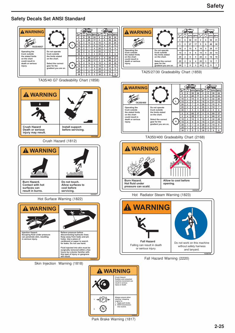
15333272
Crush Hazard.
Sudden and unwanted
machine movement can
result in serious
injury or death.
Always ensure when
starting / stopping
engine to :
1. Apply park brake.
2. Shift transmission
into neutral.
P1.
2.
WARNING
Park Brake Warning (1817)
15333273
Injection Hazard.Escaping fluid under pressurecan penetrate skin, resultingin serious injury.
Relieve pressure beforedisconnecting hydraulic lines.Keep away from leaks and pinholes. Use a piece of cardboard or paper to searchfor leaks. Do not use hand.
Fluid injected into skin must besurgically removed within a fewhours by a doctor familiar with this type of injury or gangrenewill result.
WARNING
Skin Injection Warning (1818)
15333277
Burn Hazard.Contact with hotsurfaces can result in burns.
Do not touch.Allow surfaces to cool beforeservicing.
WARNING
Hot Surface Warning (1822)
15333278
Burn Hazard.Hot fluid under pressure can scald.
Allow to cool beforeopening.
WARNING
Hot Radiator Steam Warning (1823)
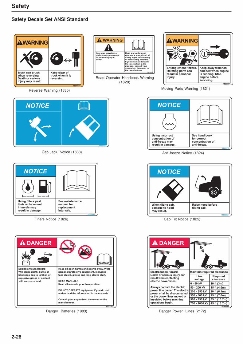
Safety Decals Set ANSI Standard
15333265
WARNING
Crush HazardDeath or serious injury may result.
Install supportbefore servicing.
Crush Hazard (1812)
WARNING
15333268
% KPH MPH % KPH MPH
0 6 50 31 0 6 50 31
5 5 27 17 5 6 48 30
10 4 15 9 10 5 28 17
15 3 9 6 15 5 22 14
20 2 8 5 20 4 16 10
25 2 6 4 25 3 12 7
30 1 5 3 30 3 11 7
Operating the truck outside the stated limitson the chartcould result indeath or seriousinjury.
Do not operatetruck outsidethe limits statedon the chart.
Select the correctgear for thegradient you are on.
TA25/27/30 Gradeability Chart (1859)
WARNING
15333267
L
H
% %KPH MPH KPH MPH
TA35/40G7
0 6 39 24 0 6 39 24
0 6 60 37 0 6 60 37
5 4 28 17 5 6 60 37
5 5 28 17 5 6 39 24
20 2 7 4 20 3 15 9
25 2 6 4 25 3 12 7
15 2 9 6 15 4 21 13
10 3 14 9 10 5 32 20
30 1 5 3 30 2 9 6
15 2 9 6 15 3 21 13
25 1 6 4 25 2 12 7
20 1 7 4 20 2 15 9
30 1 5 3 30 2 9 6
Operating the
truck outside
the stated limits
on the chart
could result in
death or serious
injury.
Do not operate
truck outside
the limits stated
on the chart.
Select the correct
gear for the
gradient you are on.
10 2 14 9 10 4 32 20
TA35/40 G7 Gradeability Chart (1858)
WARNING
15354036
L
H
% %KPH MPH KPH MPH
TA350/400
0 6 39 24 0 6 39 24
0 6 60 37 0 6 60 37
5 4 28 17 5 6 60 37
5 5 28 17 5 6 39 24
20 2 7 4 20 3 15 9
25 2 6 4 25 3 12 7
15 2 9 6 15 4 21 13
10 3 14 9 10 5 32 20
30 1 5 3 30 2 9 6
15 2 9 6 15 3 21 13
25 1 6 4 25 2 12 7
20 1 7 4 20 2 15 9
30 1 5 3 30 2 9 6
Operating the
truck outside
the stated limits
on the chart
could result in
death or serious
injury.
Do not operate
truck outside
the limits stated
on the chart.
Select the correct
gear for the
gradient you are on.
10 2 14 9 10 4 32 20
TA350/400 Gradeability Chart (2168)
Fall Hazard
Falling can result in death
or serious injury.
Do not work on this machine
without safety harness
and lanyard.
15356708
WARNING
Fall Hazard Warning (2220)
2-26
Safety
15333275
Improper operation ormaintenance can resultin serious injury ordeath.
Read and understandoperator's manual and allsafety signs before using or maintaining machine.If you do not understandthe information in the manuals, consult yoursupervisor, the owner or the manufacturer.
WARNING
Read Operator Handbook Warning
(1820)
Moving Parts Warning (1821)
Anti-freeze Notice (1824)
Cab Tilt Notice (1825)Filters Notice (1826)
15333454
Truck can crushwhen reversing.Death or seriousinjury may result.
Keep clear of truck when it isreversing.
WARNING
Reverse Warning (1835)
15334867
Explosion/Burn Hazard
Will cause death, burns or
blindness due to ignition of
explosive gases or contact
with corrosive acid.
Keep all open flames and sparks away. Wear
personal protective equipment, including
face shield, gloves and long sleeve shirt.
READ MANUALS
Read all manuals prior to operation.
DO NOT OPERATE equipment if you do not
understand the information in the manuals.
Consult your supervisor, the owner or the
manufacturer.
DANGER
Danger Batteries (1983) Danger Power Lines (2172)
Safety Decals Set ANSI Standard
15333276
Entanglement Hazard.Rotating parts canresult in personal injury.
Keep away from fan and belt when engine is running. Stop engine before servicing.
WARNING
15333279
Using incorrectconcentration ofanti-freeze mayresult in damage.
See hand bookfor correctconcentration ofanti-freeze.
NOTICE
15333280
NOTICE
When tilting cab,damage to hoodmay result.
Raise hood beforetilting cab.
15333281
NOTICE
Using filters pasttheir replacementintervals may result in damage.
See maintenancemanual for replacementintervals.
15353582
Maintain required clearanceElectrocution HazardDeath or serious injury canresult from contactingelectric power lines.
Always contact the electricpower line owner. The electricpower shall be disconnectedor the power lines moved orinsulated before machineoperations begin.
0 - 50 kV
50 - 200 kV
200 - 350 kV
350 - 500 kV
500 - 750 kV
750 - 1000 kV
10 ft (3m)
15 ft (4.6m)
20 ft (6.1m)
25 ft (7.6m)
35 ft (10.7m)
45 ft (13.7m)
Linevoltage
Requiredclearance
DANGER
NOTICE
15333288
Cab Jack Notice (1833)

2-27
Safety
NOTES ON LUBRICATION AND SERVICE CHART
NOTE 1 - CAPACITIES GIVEN ARE APPROXIMATE - WORK TO DIPSTICK, SIGHT GAUGES OR LEVEL PLUGS.
NOTE 2 - CAPACITY OF FRONT AND REAR DIFFERENTIALS 21 LTR (5.5 US GAL)
CAPACITY OF CENTRE DIFFERENTIAL IS 23 LTR (6 US GAL)
NOTE 3 - LUBRICATE SLOWLY UNTIL EXCESS LUBE IS SEEN.
NOTE 4 - REMOVE PLUG FROM PORT ON UNDERSIDE OF OSCILLATION HUB. PLUG IS REMOVED TO DRAIN THE CAVITY OF ANY OIL THAT
ENTERS THE CAVITY WHEN FILLING. REMOVE THE COVER PLATE AND LEVEL PLUG ON SIDE OF OSCILLATION HUB. ADD OIL
IF REQUIRED. REFIT ALL PLUGS.
EO - ENGINE OIL. REFER TO "RECOMMENDED LUBRICANTS".
HO - HYDRUALIC OIL. REFER TO "RECOMMENDED LURICANTS".
EPL - EXTREME PRESSUREGEAR LUBRICANT. REFER TO "RECOMENDED LUBRICANTS".
EP,NLGI - EXTREME PRESSURE LITHIUM No. 2 GREASE (WITHOUT "MOLY").
PAG OIL - POLYALKLENE GLYCOL (PAG) COMPRESSOR LUBRICATING OIL - LOW VISCOSITY (ISO46)
LUBRICATION AND SERVICE CHART
INTERVAL
HOURS
NO.
PTSREF
PTSSERVICE INSTRUCTIONS SERVICE QUANTITIES
LUBRICANT
OR COOLERIDENTIFICATION
10
DAILY
50
WEEKLY
250
MONTHLY
1
2
3
4
6
7
18
1
3
24
1
1
1
1
1
1
2
1
1
6
EO
EO
HO
ETHYLENE
GLYCOL
-
-
-
-
-
-
EP, NLGI
EP, NLGI
EP, NLGI
EP, NLGI
EP, NLGI
-
-
EP, NLGI
-
AS REQUIRED
AS REQUIRED
AS REQUIRED
REF. ENGINE MANUAL
SEC 160-0050
ENGINE
TRANSMISSION
HYDRAULIC TANK
RADIATOR EXPANSION TANK
FUEL FILTER / WATER SEPARATOR
ENGINE AIR CLEANER
DRIVE BELTS
ENGINE CRANKCASE BREATHER
HYD. FILTER RESTRICTION GAUGE
TYRES
CHECK OIL LEVEL. ADD OIL IF LOW
CHECK OIL LEVEL. ADD OIL IF LOW
CHECK OIL LEVEL. ADD OIL IF LOW
CHECK COOLANT LEVEL. ADD IF LOW
DRAIN
CHECK. RENEW ELEMENT IF REQ'D
VISUAL INSPECTION FOR DAMAGE
INSPECT. CLEAN IF REQUIRED
CHECK. RENEW ELEMENT IF REQ'D
CHECK CONDITION & PRESSURE
19
20
21
25
27
18
35
6
3
1
2
2
2
1
EPL
EPL
-
EP, NLGI
-
-
EP,NLGI
AS REQUIRED
AS REQUIRED
-
SEE NOTE 3
-
-
SEE NOTE 3
WHEEL PLANETARIES
DIFFERENTIALS
OSCILLATION PIVOT
ARTICULATION BEARINGS
PARKING BRAKE PADS
DRIVE BELTS
FRONT AXLE (IFS)
CHECK OIL LEVEL. ADD IF LOW
CHECK OIL LEVEL. ADD IF LOW
CHECK END FLOAT. ADJUST IF REQ'D
LUBE
CHECK WEAR. RENEW IF REQ'D
CHECK TENSION. TIGHTEN IF REQ'D
LUBE
9
12
10
11
13
15
30
14
8
2
2
4
4
2
72
1
4
2
SEE NOTE 3
SEE NOTE 3
SEE NOTE 3
SEE NOTE 3
SEE NOTE 3
600 Nm / 442 lbf ft
SEE NOTE 3
AS REQUIRED
OSCILLATION BUSHES
SUSPENSION BEAM BUSHINGS
STEERING CYLINDER PINS
BODY CYLINDER PINS
BODY HINGE /TAILGATE PINS
WHEEL RIM NUTS
CAB FRESH AIR FILTER
PANHARD ROD BEARINGS
BATTERY ELECTROLITE
LUBE
LUBE
LUBE
LUBE
LUBE
CHECK TORQUE
INSPECT & CLEAN IF REQUIRED
LUBE
CHECK LEVEL. ADD ELECTRO IF LOW
15347627
500
3 MONTH
1
16
1
1
EO
-
-
-ENGINE
ENGINE OIL FILTER
DRAIN OIL & REFILL WITH NEW OIL
RENEW
40005
33
-
1
-
PAG OIL
-
-
COOLING SYSTEM
AIR CON. COMPRESSOR
DRAIN, FLUSH & REFILL WITH NEW
COOLANT
DRAIN, FLUSH & REFILL WITH NEW
REFRIGERANT OIL
1000
6 MONTH
2000
ANNUALLY
2
2
3
6
17
2
28
29
22
30
32
1
1
1
1
1
1
2
1
1
1
1
EO
-
-
-
-
-
-
-
EPL
-
-
-
-
REF. SERVICE MANUAL
-
-
-
-
-
SEE NOTE 4
-
-
TRANSMISSION
TRANSMISSION
HYDRAULIC TANK BREATHER
FUEL FILTER / WATER SEPARATOR
DCA4 COOLANT FILTER
TRANSMISSION BREATHER
TRANSMISSION OIL FILTERS
TRANSMISSION INTERNAL
STRAINER
DRIVESHAFT BEARINGS
CAB FRESH AIR FILTER
FUEL TANK
DRAIN OIL & REFILL WITH NEW OIL
RUN AEB STARTER
RENEW
RENEW
RENEW
CLEAN IF REQUIRED
RENEW
CLEAN
CHECK OIL LEVEL. ADD IF LOW
RENEW
RENEW CAP FILTER / CATRIDGE
3
19
19
20
25
31
3
23
1
2
1
1
34
1
6
6
3
1
1
1
5
4
3
4
1
24
HO
-
EPL
EPL
-
-
-
-
-
-
-
-
-
-
REF. SERVICE MANUAL
-
SEE NOTE 2
1425 Nm / 1050 lbf ft
-
-
-
298 Nm / 220 lbf ft
920 Nm / 679 lbf ft
65 Nm / 50 lbf ft
-
671 Nm / 495 lbf ft
HYDRAULIC TANK
BRAKE PACKS
WHEEL PLANETARIES
DIFFERENTIALS
ARTICULATION PIVOT NUT
HYDRAULIC OIL FILTER
HYDRAULIC TANK STRAINER
DRIVELINES
ENGINE MOUNTING BOLTS
TRANSMISSION MOUNTING BOLTS
TURBOCHARGER MOUNTING
BOLTS
ENGINE WATER PUMP
AXLE MOUNTING BOLTS
DRAIN OIL & REFILL WITH NEW OIL
CHECK BRAKE WEAR
DRAIN OIL & REFILL WITH NEW OIL
DRAIN OIL & REFILL WITH NEW OIL
CHEK TORQUE
RENEW
CLEAN
CHECK FOR LEAKS & DAMAGE
CHECK TORQUE
CHECK TORQUE
CHECK TORQUE
INSPECT DRAIN HOLE.
CLEAN IF REQUIRED
CHECK TORQUE
17
33
8
6
16
7
29
2
28
35
10
11
9
21
19
23
12
15
26
34
14
24
13
20
27
22
25
31
30
32
18
1
5
4
3
TA25/27/30 Service Lubrication Chart (2191)
Safety Decals Set ANSI Standard
Jump Start Notice (1827)
Nitrogen Filled Tyres Notice
(1828)
Power Down Notice (1829)15333282
NOTICE
Jump starting withwelding equipment willresult in damage to the electrial system.
Jump start usingidentical batterypack.
NOTICE
15333283
Use nitrogen onlyto inflate tyres.
AIR N
15333284
NOTICE
Power down truckwhen not in useor damage mayoccur.

2-28
Safety
15334870
WARNING
Fall HazardDeath or seriousinjury can resultfrom falling.
Use the accesssystem providedwhen servicingthe machine.
Fall Hazard Warning (1986)
TA350/400 Service Lubrication Chart (1795)
Safety Decals Set ANSI Standard
Welding Notice (1830)
WARNING
PSI / BAR
0
Explosion HazardDeath or seriousinjury can resultfrom release ofpressurised liquids.
Do not weld or drillinto accumulator.Keep away from flames.Relieve all pressure before performingservice on accumulator.
15334869
Accumulator Warning (1985)15333285
NOTICE
Welding truck can seriouslydamage ECUs andcomponents.
Disconnect the following,in order, before welding:1. Turn off master switch.2. Battery earth cable.3. Battery supply cable.4. Alternator earth cable.5. Alternator supply cable.6. Body control lever.7. Engine ECM.8. Transmission ECU.9. Hydraulic ECU.10. Instrument panel ECU.11. Cab bulkhead connectors
1
31
5
733 32 4 3 30 15 2 12 21 14 34 22 26 17 20 8 23
13
28
35
24
29 11 9 12 18 19 25 17 16 10
6
27
NOTES ON LUBRICATION AND SERVICE CHART
NOTE 1 - CAPACITIES GIVEN ARE APPROXIMATE - WORK TO DIPSTICK, SIGHT GAUGES OR LEVEL PLUGS.
NOTE 2 - CHECK WITH THE ENGINE IDLING AND THE TRANSMISSION AT ITS NORMAL OPERATING TEMPERATURE.
NOTE 3 - LUBRICATE SLOWLY UNTIL EXCESS LUBE IS SEEN.
NOTE 4 - REMOVE PLUGS AND FIT LUBE FITTINGS. LUBRICATE SLOWLY UNTIL EXCESS LUBE IS SEEN. REMOVE FITTINGS AND REFIT PLUGS.
NOTE 5 - CAPACITY OF FRONT AND REAR DIFFERENTIALS 33 LITRE (8.7 USGAL). CAPACITY OF CENTRE DIFFERENTIAL 34 LITRE (9USGAL)
PLUS 1 LITRE (2 PINTS) FOR PRIMING THE 3RD DIFFERENTIAL UNIT. (36 LITRE EPL + 2 LITRE LZ 6178).
NOTE 6 - REMOVE PLUG FROM PORT ON UNDERSIDE OF OSCILLATION HUB. PLUG IS REMOVED TO DRAIN THE CAVITY OF ANY OIL THAT ENTERS
THE CAVITY WHEN FILLING. REMOVE GROMMET AND LEVEL PLUG ON SIDE OF OSCILLATION HUB. ADD OIL IF REQUIRED. REFIT ALL PLUGS.
NOTE 7 - CHECK DROPBOX LEVEL COLD WITH ENGINE RUNNING.
EO - ENGINE OIL. REFER TO "RECOMMENDED LUBRICANTS".
HO - HYDRUALIC OIL. REFER TO "RECOMMENDED LURICANTS".
EPL - EXTREME PRESSURE LUBRICANT SPEC. MIL-L21058.
EP,NLGI - EXTREME PRESSURE LITHIUM No. 2 GREASE (WITHOUT "MOLY"). REF. EEMS 19014
EP,LI COMP - EXTREME PRESSURE LITHIUM GREASE. REF. EEMS 19057.
LZ - LUBRIZOL 6178
PAG OIL - POLYALKLENE GLYCOL (PAG) COMPRESSOR LUBRICATING OIL - LOW VISCOSITY (ISO46).
LUBRICATION AND SERVICE CHART
INTER-VAL
HOURS
NO.OF
PTS
REFNO.
SERVICEINSTRUCTIONS
SERVICEQUANTITIES
LUBRICANTOR COOLANT
IDENTIFICATION
10
DAILY
11234
51432
116
27
11111
111
16
EO
TRANSYNDHOETHYLENE GLYCOL
AS REQUIRED
SEE NOTE 2AS REQUIREDAS REQUIRED
SEE NOTE 7AS REQUIRED
ENGINEENGINE CRANKCASE BREATHERTRANSMISSIONHYDRAULIC TANKRADIATOR EXPANSION TANK
PRIMARY FUEL FILTER/WATER SEPDROPBOXOCDB TANK
ENGINE AIR CLEANERDRIVE BELTTYRES
CHECK OIL LEVEL. ADD OIL IF LOWINSPECT AND CLEAN IF REQUIREDCHECK OIL LEVEL. ADD OIL IF LOWCHECK OIL LEVEL. ADD OIL IF LOWCHECK COOLANT LEVEL. ADD IF LOW
CHECK. DRAIN AS REQUIREDCHECK OIL LEVEL. ADD OIL IF LOWCHECK OIL LEVEL. ADD OIL IF LOW
CHECK. RENEW ELEMENT IF REQUIREDVISUAL INSPECTION FOR DAMAGECHECK CONDITION & PRESSURE
25
151617181925
6
111362121
EPL & LZEPL EP LI COMP
AS REQUIREDAS REQUIREDSEE NOTE 3 & 4
TRANSMISSION BREATHERPRIMARY FUEL FILTER/WATER SEPSECONDARY FUEL FILTERDIFFERENTIALSWHEEL PLANETARIESARTICULATION BEARINGSOSCILLATION PIVOTPARKING BRAKE PADSDRIVE BELT
CLEAN IF RQUIREDRENEWRENEWCHECK OIL LEVEL. ADD IF LOWCHECK OIL LEVEL. ADD IF LOWLUBECHECK END FLOAT. ADJUST IF REQUIREDCHECK WEAR. REPLACE IF REQUIREDCHECK TENSION. TIGHTEN IF REQUIRED
1131414
1211
EO
EO
32 LITRES / 8.4 US GAL
13 LITRES / 3.4 US GAL
ENGINEENGINE OIL FILTERSDROPBOXDROPBOX OIL FILTERS
DRAIN OIL AND REFILL WITH NEW OILRENEWDRAIN OIL AND REFILL WITH NEW OILRENEW
115 LITRES / 30.5 US GAL
50
WEEKLY
250
MONTHLY
16171128
929303126
36
11111
EPL & LZEPL
EPL
SEE NOTE 59 LITRE / 2.4 US GAL
SEE NOTE 6
DIFFERENTIALSWHEEL PLANETARIESENGINE AIR CLEANERCOOLANT ADDATIVECAB FRESH AIR FILTERFUEL TANK BREATHERHYDRAULIC TANK BREATHEROCDB TANK BREATHERDRIVESHAFT BEARINGS
DRAIN OIL AND REFILL WITH NEW OILDRAIN OIL AND REFILL WITH NEW OILRENEW ELEMENTRENEWRENEWRENEWRENEWRENEWCHECK OIL LEVEL. ADD IF LOW
1000
6 MONTH
336
24
34211
1111
1222
HO
ETHYLENE GLYCOL
298 LITRE / 79 US GAL
67 LITRES / 18 US GAL
1425 Nm / 1050 lbf ft 921 Nm / 680 lbf ft 921 Nm / 680 lbf ft 330 Nm / 239 lbf ft
HYDRAULIC TANKHYDRAULIC OIL FILTERDRIVE BELTCOOLING SYSTEM
ARTICULATION PIVOT NUTTRANSMISSION MTG. BOLTSTURBOCHARGER MTG. NUTSENGINE MOUNTING BOLTS
DRAIN OIL AND REFILL WITH NEW OILRENEWRENEW BELTCHECK CONCENTRATION. ADD BOOSTER
CHECK TORQUE (TORQUE SEAL)CHECK TORQUE (TORQUE SEAL)CHECK TORQUE (TORQUE SEAL)CHECK TORQUE (TORQUE SEAL)
2000
ANNUALLY
500
3 MONTH
32
3333
1
11
TEXTRAN TDHPREMIUM
EOTEXTRAN TDHPREMIUM
OCDB TANK
OCDB FILTEROCDB STRAINER
DRAIN OIL AND REFILL WITH NEW OIL
RENEWCLEAN
1500
9 MONTH
12 2TRANSMISSION OIL FILTERS RENEW3000
2 1TRANSMISSION DRAIN OIL AND REFILL WITH NEW OIL6000
0.125 LITRES PAG OIL 35 1
61 LITRES / 16 US GAL TRANSYND1
AIR CONDITIONING COMPRESSOR DRAIN FLUSH AND REFILL WITH NEW OIL4000
789
101920212223
21141422442
EP. NLGIEP, NLGIEP, NLGIEP, NLGIEP, NLGIEP, NLGI
AS REQUIRED600 Nm / 442 lbf ft
SEE NOTE 3SEE NOTE 3SEE NOTE 3SEE NOTE 3SEE NOTE 3SEE NOTE 3
BATTERY ELECTROLITEWHEEL RIM NUTSCAB FRESH AIR FILTERPANHARD ROD BEARINGSOSCILLATION BUSHSUSPENSION BEAM BUSHINGSSTEERING CYLINDER PINSBODY CYLINDER PINSBODY HINGE PINS/TAILGATE PINS
CHECK LEVEL. ADD ELECTROLITE IF LOWCHECK TORQUEINSPECT AND CLEAN IF REQUIREDLUBELUBELUBELUBELUBELUBE
15353114
Crush From Articulation Warning (1810)
Crush HazardDeath or serious injuryfrom crushing can occurin articulating areawhen machine turns.
Before servicing:1. Turn key switch off and remove key.2. Install articulation lock arm.
15333263
WARNING
Hydraulic Tank Pressurization Warning (2021)
15343324
WARNING
Pressurisedhydraulic tank.
Before working on thetank, open the ball valveto remove pressure.Close valve afterpressure has relieved.
PSI / BAR
0
AIR
OIL
Accumulators.Incorrectly maintainedaccumulators can resultin brake failure, whichcan result in death or serious injury.
Maintain nitrogen precharge in accumulatorsfor proper operation ofbrake system.Read manual for brakesystem imformation.
15333270
N2
PSI / BAR
0WARNING
Accumulator Warning (1922)

3-1
Controls and Operating
3 - Controls and Operating

3-2
Controls and Operating
This Page Intentionally Left Blank
3-3
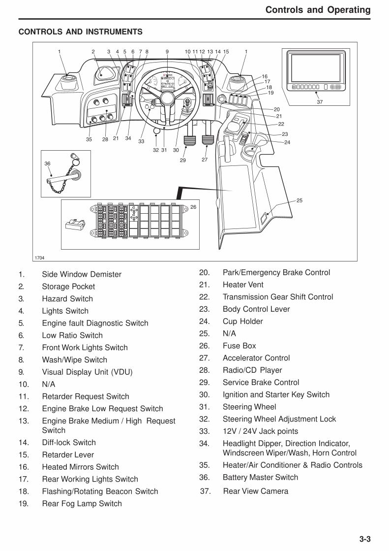
Controls and Operating
1704
1. Side Window Demister
2. Storage Pocket
3. Hazard Switch
4. Lights Switch
5. Engine fault Diagnostic Switch
6. Low Ratio Switch
7. Front Work Lights Switch
8. Wash/Wipe Switch
9. Visual Display Unit (VDU)
10. N/A
11. Retarder Request Switch
12. Engine Brake Low Request Switch
13. Engine Brake Medium / High Request
Switch
14. Diff-lock Switch
15. Retarder Lever
16. Heated Mirrors Switch
17. Rear Working Lights Switch
18. Flashing/Rotating Beacon Switch
19. Rear Fog Lamp Switch
20. Park/Emergency Brake Control
21. Heater Vent
22. Transmission Gear Shift Control
23. Body Control Lever
24. Cup Holder
25. N/A
26. Fuse Box
27. Accelerator Control
28. Radio/CD Player
29. Service Brake Control
30. Ignition and Starter Key Switch
31. Steering Wheel
32. Steering Wheel Adjustment Lock
33. 12V / 24V Jack points
34. Headlight Dipper, Direction Indicator,
Windscreen Wiper/Wash, Horn Control
35. Heater/Air Conditioner & Radio Controls
36. Battery Master Switch
CONTROLS AND INSTRUMENTS
37. Rear View Camera
PSTOP
1
2
10
10
20
3040
50
60
70
80
km/h
20 30
40mph
50 300 0
5r / min x100
10 20
25
15
4070 100
150105
210250
120 60
140
275 320390
135 165
200
˚C
˚F
˚C
˚F
L HMENU SELECT DN UP + -
1 2 3 4 5 6 7 8 9 10 11 12 13 14 15 1
16171819
20
21
22
23
26
2729
303132
333435 28
36
2124
25
37
3-4
Controls and Operating
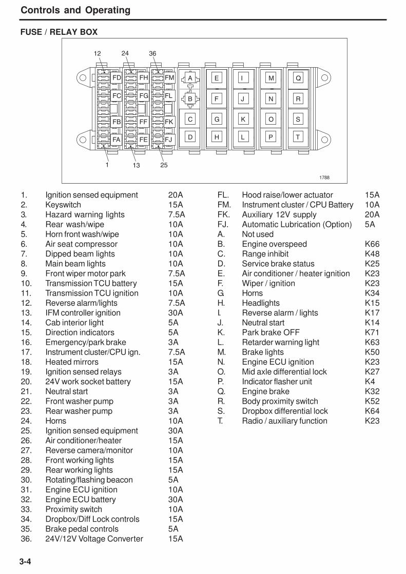
FUSE / RELAY BOX
1. Ignition sensed equipment 20A FL. Hood raise/lower actuator 15A
2. Keyswitch 15A FM. Instrument cluster / CPU Battery 10A
3. Hazard warning lights 7.5A FK. Auxiliary 12V supply 20A
4. Rear wash/wipe 10A FJ. Automatic Lubrication (Option) 5A
5. Horn front wash/wipe 10A A. Not used
6. Air seat compressor 10A B. Engine overspeed K66
7. Dipped beam lights 10A C. Range inhibit K48
8. Main beam lights 10A D. Service brake status K25
9. Front wiper motor park 7.5A E. Air conditioner / heater ignition K23
10. Transmission TCU battery 15A F. Wiper / ignition K23
11. Transmission TCU ignition 10A G. Horns K34
12. Reverse alarm/lights 7.5A H. Headlights K15
13. IFM controller ignition 30A I. Reverse alarm / lights K17
14. Cab interior light 5A J. Neutral start K14
15. Direction indicators 5A K. Park brake OFF K71
16. Emergency/park brake 3A L. Retarder warning light K63
17. Instrument cluster/CPU ign. 7.5A M. Brake lights K50
18. Heated mirrors 15A N. Engine ECU ignition K23
19. Ignition sensed relays 3A O. Mid axle differential lock K27
20. 24V work socket battery 15A P. Indicator flasher unit K4
21. Neutral start 3A Q. Engine brake K32
22. Front washer pump 3A R. Body proximity switch K52
23. Rear washer pump 3A S. Dropbox differential lock K64
24. Horns 10A T. Radio / auxiliary function K23
25. Ignition sensed equipment 30A
26. Air conditioner/heater 15A
27. Reverse camera/monitor 10A
28. Front working lights 15A
29. Rear working lights 15A
30. Rotating/flashing beacon 5A
31. Engine ECU ignition 10A
32. Engine ECU battery 30A
33. Proximity switch 10A
34. Dropbox/Diff Lock controls 15A
35. Brake pedal controls 5A
36. 24V/12V Voltage Converter 15A
A
B
C
D
E
F
G
H
I
J
K
L
M
N
O
P
Q
R
S
T
FM
FL
FK
FJ
FH
FG
FF
FE
FD
FC
FB
FA
12
131
3624
25
1788
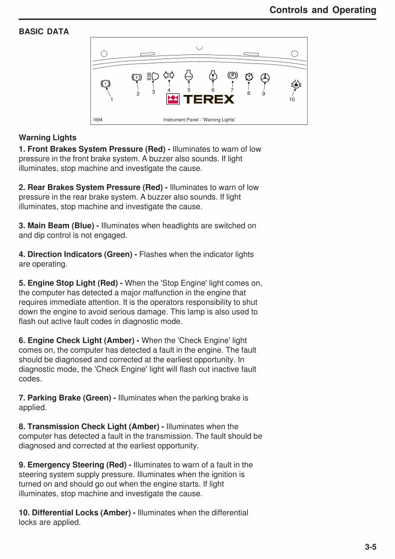
3-5
Controls and Operating
BASIC DATA
PSTOP
1
2
1 102 93 8
4 75 6
1694 Instrument Panel - 'Warning Lights'
Warning Lights
1. Front Brakes System Pressure (Red) - Illuminates to warn of low
pressure in the front brake system. A buzzer also sounds. If light
illuminates, stop machine and investigate the cause.
2. Rear Brakes System Pressure (Red) - Illuminates to warn of low
pressure in the rear brake system. A buzzer also sounds. If light
illuminates, stop machine and investigate the cause.
3. Main Beam (Blue) - Illuminates when headlights are switched on
and dip control is not engaged.
4. Direction Indicators (Green) - Flashes when the indicator lights
are operating.
5. Engine Stop Light (Red) - When the 'Stop Engine' light comes on,
the computer has detected a major malfunction in the engine that
requires immediate attention. It is the operators responsibility to shut
down the engine to avoid serious damage. This lamp is also used to
flash out active fault codes in diagnostic mode.
6. Engine Check Light (Amber) - When the 'Check Engine' light
comes on, the computer has detected a fault in the engine. The fault
should be diagnosed and corrected at the earliest opportunity. Indiagnostic mode, the 'Check Engine' light will flash out inactive fault
codes.
7. Parking Brake (Green) - Illuminates when the parking brake is
applied.
8. Transmission Check Light (Amber) - Illuminates when the
computer has detected a fault in the transmission. The fault should be
diagnosed and corrected at the earliest opportunity.
9. Emergency Steering (Red) - Illuminates to warn of a fault in the
steering system supply pressure. Illuminates when the ignition is
turned on and should go out when the engine starts. If light
illuminates, stop machine and investigate the cause.
10. Differential Locks (Amber) - Illuminates when the differential
locks are applied.

3-6
Controls and Operating
VDU - 'Warning Screen'2175
Warning Symbols
Note: Contained on the Warning screen of the VDU, this displays all
possible symbols displayed on 3-lines ( top to bottom) as shown.
1. Low Fuel - Indicates that the level of fuel in the system should be
monitored and action to rectify this is imminent.
2. Alternator Charging - Indicates that the system batteries are in a
state of overcharging, undercharging or battery voltage low.
3. Hydraulic Oil Filter Change - Notifies the operator that the hydraulic
oil filter is restricted and should be replaced.
4. Engine Air filter Change - Notifies the operator that the air filter is
restricted and should be cleaned / replaced accordingly.
5. Oil Brake Cooling Pressure - Indicates that the brake cooling
pressure is outwith the prescribed operating range and should be
investigated.
6. Hydraulic Oil Level - Notifies the operator that the hydraulic oil level
in the hydraulic tank is low, replenish the hydraulic oil accordingly.
7. Brake Cooling Oil Temperature - Indicates that brake cooling oil
temperature is outwith the prescribed operating range and should be
investigated.
8. Body Up - Indicates the body has been raised and is off the chassis
bed. Transmission upshift is restricted while this light is illuminated.
9. Transmission Oil Temperature High - Indicates that the temperature
of the oil in the transmission is at a critical level, outwith the prescribed
operating range for the system and should be investigated.
10. Transmission Drop Box Oil Temperature High - Indicates that
drop box oil temperature is at a level outwith the prescribed operating
range and should be investigated.
11. Transmission Drop Box High/ Low Oil Pressure - Indicates that
the drop box oil pressure is outwith the prescribed operating range and
should be investigated.
12. Retarder - Indicates that the retarder has been requested and is
active. It will remain till the retarder is deactivated.
13. Engine Brake - Indicates that the engine jake brake has been
requested and is active. It will remain till the brake is deactivated.
14. Transmission Dropbox, Low Ratio Selected - Indicates that the
drop box is engaged in low ratio.
15. Transmission Drop box, High Ratio Selected - Indicates that the
drop box is engaged in high ratio.
L H
1 2 3 4 5
896
107
15
11121314

3-7
Controls and Operating
Instruments
2174 Instrument Panel
1. Engine Water Temperature Gauge - This gauge should read in
the green sector after the engine has warmed. If the gauge reads
above this, (the red sector) stop the engine and investigate the cause.
2. Speedometer - The speedometer indicates travel speed in
kilometres per hour (displayed grey) and miles per hour, (displayed
white). A digital odometer is centred at the base of the speedometer,
consiting of a 2-line LCD. The upper line displays 7-digits, which
show the total miles travelled. The lower line displays a 4-digit
reading which displays the trip mileage. The trip mileage can be reset
by pressing the reset button for approximately 1 second. The
readings can be used for operating and service records.
3. Tachometer - Driven from the engine ECU, the tachometer
indicates the number of engine crankshaft revolutions per minute.
The needle shows the variations in engine operating speed. Never
accelerate the engine to speeds indicated by the red zone on the dial
face.
4. Transmission Oil Temperature Gauge - Indicates transmission
oil operating temperature. Gauge should read in the green sector
during normal operation and may enter the yellow sector when using
the retarder or in converter mode. If the gauge reads above this (the
red area), stop the vehicle and investigate the cause.
5. Visual Display Unit (VDU) - Monochrome LCD display. Centred in
the instrument panel. This unit is the primary monitor within the
instrument panel. The screen holds and displays critical systems
information based on the inputs which are received from the various
vehicle sensors and monitors.
6. Dimming Button - To dim or increase the illumination for the
instruments on the VDU.
7. Not used - (Buttons blanked-off)
PSTOP
1
2
10
10
20
3040
50
60
70
80
km/h
20 30
40mph
50 300 0
5r / min x100
10 20
25
15
4070 100
150105
210250
120 60
140
275 320390
135 165
200
˚C
˚F
˚C
˚F
0000000
0000
L H
1 48 7 6 5
2 3

3-8
Controls and Operating
8. Reset Button - Trip counter reset button, when depressed for
approx. 1 second, will reset the trip.
'Start-Up' Screen1692a
'Warning' Sceen2175
Fuel Level
Voltmeter
00000
0
8 12 16 20 24 28 32
25 50 75
50 75 100 125 150
100
Brake Cooling
L H
1
2
3
8764 5'Main' Screen1692c
The following show the multi-level display in its 3 possible
conditions. On initial starting of the vehicle, the VDU will display the
screens and scroll through them in the order in which they are
displayed here, assuming the system is in correct working order.
Screen 1- Displays the TEREX logo and program part number.
Screen 2- Displays the Warning screen, consisting of Warning
symbol graphics which have been pre-programmed into the system.
(These are described in the BASIC DATA, Warning lights/symbol
section prior to this.)
Screen 3 - Main Screen, this is the default screen which will remain
active at all times, unless another screen has been activated via a
warning or is triggered by the operator requesting a screen change
using the request button. If an active warning is present the VDU will
toggle between screen 3 and screen 2. The screens will toggle
between 'warning' and 'main' screen until the warning light
disappears. The main screen contains information / monitoring of the
following vehicle functions-
1. Fuel level - Bargraph monitors fuel level within the tank. Should
the fuel level drop below 25% a warning light (1) on the instrument
display will light. Capacity 450 litres (119 US gal). Fill the tank
overnight to minimise condensation in the tank. Avoid a dry tank
condition which requires bleeding the fuel system.
2. System Voltage - Monitors the potential voltage on the system.
Should the level drop to a critical level, indicating a discharged
battery / fault, a warning light (2) on the instrument display will light.
3. Brake Cooling - Monitors brake oil temperature, should the temp
rise above 60°C (140°F), a warning light (7) will illuminate.
4. Retarder - Indicates that the transmission retarder has been
requested and is active.
Visual Display Unit (VDU)
L H
1 2 3 4 5
896
107
15
11121314

3-9
Controls and Operating
1692c
5. Engine Brake - Indicates that the engine jake brake has been
requested and is active.
6. Engine Hours Counter - Records the number of hours on the
engine.
7. Transmission Drop box, Low Ratio Selected - Indicates that the
drop box is engaged in low ratio.
8. Transmission Drop box, High Ratio Selected - Indicates that the
drop box is engaged in high ratio.
Fuel Level
Voltmeter
00000
0
8 12 16 20 24 28 32
25 50 75
50 75 100 125 150
100
Brake Cooling
L H
1
2
3
8764 5'Main' Screen
Switches
1. Hazard Warning Lights - Press bottom of switch to make
indicators flash simultaneously as hazard warning lights. The
direction indicator warning lamp on the instrument panel will flash. To
switch hazard lights off; press the top of the switch.
2. Main Lights - Press the bottom of switch to the first postion to
operate side, tail and panel lights. The lights in the other switches will
illuminate. Press switch to the second position to operate the
headlights. To switch lights off; press the top of the switch.
3. Engine Diagnostic Switch - To check for active fault codes:a. - Turn the ignition key switch to position ‘1’.
b. - Press the diagnostic switch to the 'ON' position.
Any active codes will then be flashed out on the engine ‘STOP’ light
followed by any inactive codes being flashed out on the engine
‘CHECK’ light. A flash code ‘25’ indicates that the engine ECU is
clear of any faults. Refer to pages 3-23 to 3- 29 for details of the fault
codes.
4. Drop box - Low Ratio Request Switch - Pressing bottom of
switch engages the low gear ratio in the dropbox. With the switch in
the off position the drop box defaults to the high ratio.
Note: It is only possible to select ratio when certain conditions are
met; (See page 3-37)
The relevant high/low ratio symbol will illuminate on the VDU.
5. Front Working Lights - Press bottom of switch to operate the front
work lights. To switch off, press top of switch.
6. Rear Wash/Wipe - Press bottom of switch to operate the rear
screen wiper. Press the switch again for wash. To switch Off; press
the top of the switch.
2139 Left of instrument panel
H
1
2
3
4
5
6

3-10
Controls and Operating
7. Retarder Request Switch - Press bottom of switch to request the
transmission retarder. To disengage the retarder press the switch to
the off position. The retarder symbol will illuminate on the VDU when
the retarder is activated.
8. Engine Brake Low Request Switch - Press bottom of switch to
request the engine brake 'Low'. The engine brake symbol will
illuminate on the VDU when the engine Jake brake is activated.
9. Engine Brake - Medium / High Request Switch - Different levels
of engine braking can be attained by using this switch when the
engine brake request switch has been activated. Pressing the top of
the switch forward once will request 'medium' braking, pressing the
top of the switch forward to the second switch position will then
request engine brake 'high'. Only when the engine brake request
switch is pressed and active will the switch for greater levels of
braking be operative. Otherwise switch will be inactive.
10. Differential Lock Request Switch - Press bottom of switch to
engage the inter-axle differential locks. The differential lock warning
lamp on the instrument panel will illuminate. Pressing the switch to
the off position will disengage the differential locks.
11. Retarder Lever - The transmission retarder has six stages of
retardation. When the retarder is engaged it is at its maximum level
when the retarder lever is in its downmost position. When the lever is
at its uppermost position the retarder is Off.
12. Heated Mirrors - Press bottom of switch to activate the heated
mirrors. To switch off; press top of switch.
13. Rear Working Lights - Press bottom of switch to operate rear
working lights. To switch off; press top of switch.
14. Flashing/Rotating Beacon - Press bottom of switch to operate
flashing/rotating beacon. To switch off; press top of switch.
15. Rear Fog Lamp - Press bottom of switch to operate rear fog lamp.
To switch off; press top of switch.
16. Body Lower Emergency Switch - Not currently fitted to
TA350/400 machines.
2140 Right of instrument panel
161501
2141 Right Bank
7
8
9
10
11
1213 14 15
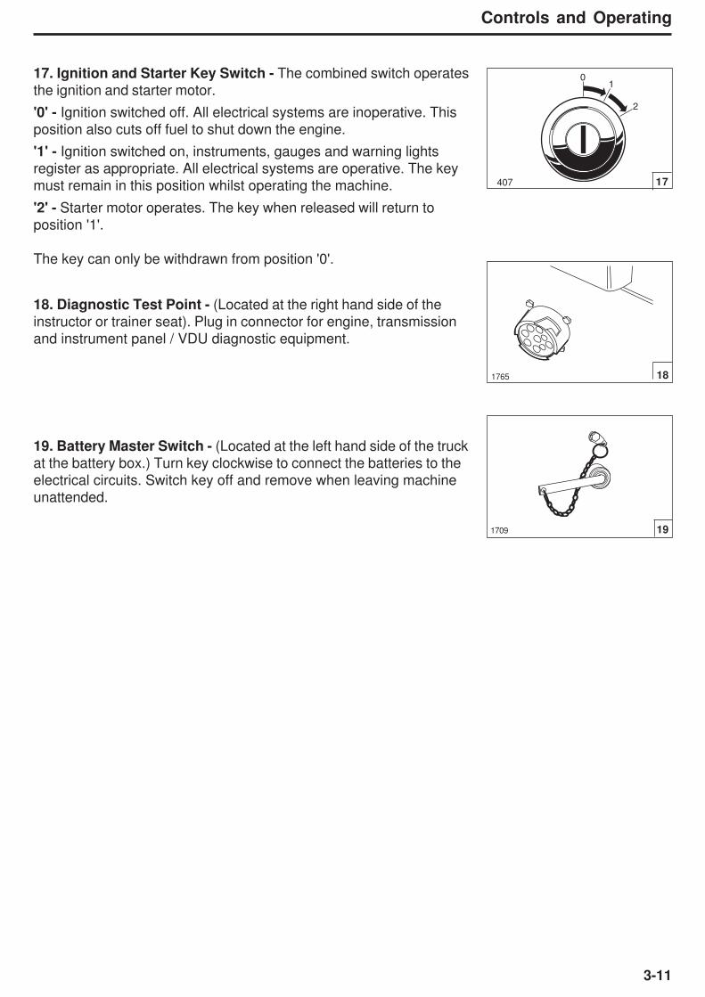
3-11
Controls and Operating
1765
17. Ignition and Starter Key Switch - The combined switch operates
the ignition and starter motor.
'0' - Ignition switched off. All electrical systems are inoperative. This
position also cuts off fuel to shut down the engine.
'1' - Ignition switched on, instruments, gauges and warning lights
register as appropriate. All electrical systems are operative. The key
must remain in this position whilst operating the machine.
'2' - Starter motor operates. The key when released will return to
position '1'.
The key can only be withdrawn from position '0'.
18
191709
18. Diagnostic Test Point - (Located at the right hand side of the
instructor or trainer seat). Plug in connector for engine, transmission
and instrument panel / VDU diagnostic equipment.
19. Battery Master Switch - (Located at the left hand side of the truck
at the battery box.) Turn key clockwise to connect the batteries to the
electrical circuits. Switch key off and remove when leaving machine
unattended.
01
2
407 17

3-12
Controls and Operating
Controls
Headlight Dipper, Direction Indicator, Windscreen Wiper/Washer
and Horn
1. Headlight Dipper and Flasher:
Neutral Position = Dipped Beam
Control Rearwards = Headlight Flash
Control Rearwards
with main lights on = Main beam
1710 1
1711 2
1712 3
1713 44444
3. Windscreen Wiper/Washer:
Position 0 = Neutral Position
Position 1 = Intermittent Sweep
Position 2 = Wiper Slow Speed
Position 3 = Wiper Fast Speed
Slide grip inward = Windscreen Wash
2. Direction Indicator:
Control Downwards = Left Indicators
Control Upwards = Right Indicators
4. Horn:Button pushed in = Horn Sounds
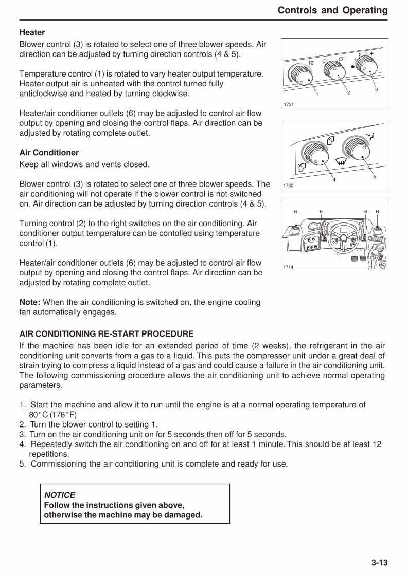
3-13
Controls and Operating
Heater
Blower control (3) is rotated to select one of three blower speeds. Air
direction can be adjusted by turning direction controls (4 & 5).
Temperature control (1) is rotated to vary heater output temperature.
Heater output air is unheated with the control turned fully
anticlockwise and heated by turning clockwise.
Heater/air conditioner outlets (6) may be adjusted to control air flow
output by opening and closing the control flaps. Air direction can be
adjusted by rotating complete outlet.
Air Conditioner
Keep all windows and vents closed.
Blower control (3) is rotated to select one of three blower speeds. The
air conditioning will not operate if the blower control is not switched
on. Air direction can be adjusted by turning direction controls (4 & 5).
Turning control (2) to the right switches on the air conditioning. Air
conditioner output temperature can be contolled using temperature
control (1).
Heater/air conditioner outlets (6) may be adjusted to control air flow
output by opening and closing the control flaps. Air direction can be
adjusted by rotating complete outlet.
Note: When the air conditioning is switched on, the engine cooling
fan automatically engages.
1731
1
2 3
321
17304
5
1714
6 6 6 6
AIR CONDITIONING RE-START PROCEDURE
If the machine has been idle for an extended period of time (2 weeks), the refrigerant in the air
conditioning unit converts from a gas to a liquid. This puts the compressor unit under a great deal of
strain trying to compress a liquid instead of a gas and could cause a failure in the air conditioning unit.
The following commissioning procedure allows the air conditioning unit to achieve normal operating
parameters.
1. Start the machine and allow it to run until the engine is at a normal operating temperature of
80°C (176°F)
2. Turn the blower control to setting 1.
3. Turn on the air conditioning unit on for 5 seconds then off for 5 seconds.
4. Repeatedly switch the air conditioning on and off for at least 1 minute. This should be at least 12
repetitions.
5. Commissioning the air conditioning unit is complete and ready for use.
NOTICE
Follow the instructions given above,
otherwise the machine may be damaged.

3-14
Controls and Operating
Operator's Seat - Air Suspension
The air seat only reacts when the driver sits on the
seat. When unoccupied, the seat sinks to the lowest
position to allow easier access.
The following is the list of controls to adjust the seat:
1. Height and weight adjustment.
2. Horizontal adjustment (sliderails).
3. Adjustable damper.
4. Seat belt.
5. Backrest angle adjustment.
6. Headrest height adjustment.
7. Fore/Aft isolator (forward position - unlocked,
rearmost position - locked).
8. Seat cushion fore/aft adjustment.
9. Seat cushion angle adjustment.
10. Lumber support adjustment.
11. Arm rest adjustment (x2).
2081
Do not attempt to adjust the seat or the seat beltwhile the machine is moving. Loss of control mayresult. Stop the machine; apply the brakes; thencarry out adjustments.
6
9
10
(behind)
115
3
2
4
1
87
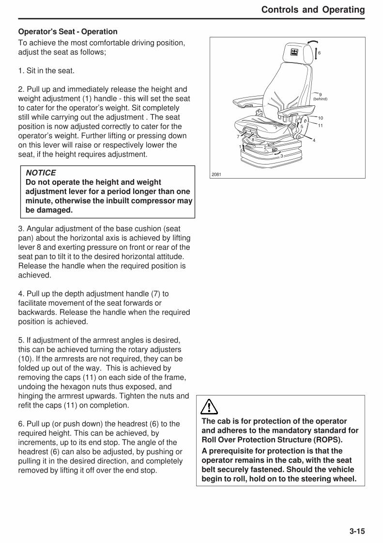
3-15
Controls and Operating
Operator's Seat - Operation
To achieve the most comfortable driving position,
adjust the seat as follows;
1. Sit in the seat.
2. Pull up and immediately release the height and
weight adjustment (1) handle - this will set the seat
to cater for the operator’s weight. Sit completely
still while carrying out the adjustment . The seat
position is now adjusted correctly to cater for the
operator’s weight. Further lifting or pressing down
on this lever will raise or respectively lower the
seat, if the height requires adjustment.
NOTICE
Do not operate the height and weight
adjustment lever for a period longer than one
minute, otherwise the inbuilt compressor maybe damaged.
3. Angular adjustment of the base cushion (seat
pan) about the horizontal axis is achieved by lifting
lever 8 and exerting pressure on front or rear of the
seat pan to tilt it to the desired horizontal attitude.
Release the handle when the required position is
achieved.
4. Pull up the depth adjustment handle (7) to
facilitate movement of the seat forwards or
backwards. Release the handle when the required
position is achieved.
5. If adjustment of the armrest angles is desired,
this can be achieved turning the rotary adjusters
(10). If the armrests are not required, they can be
folded up out of the way. This is achieved by
removing the caps (11) on each side of the frame,
undoing the hexagon nuts thus exposed, and
hinging the armrest upwards. Tighten the nuts and
refit the caps (11) on completion.
6. Pull up (or push down) the headrest (6) to the
required height. This can be achieved, by
increments, up to its end stop. The angle of the
headrest (6) can also be adjusted, by pushing or
pulling it in the desired direction, and completely
removed by lifting it off over the end stop.
The cab is for protection of the operator
and adheres to the mandatory standard forRoll Over Protection Structure (ROPS).
A prerequisite for protection is that theoperator remains in the cab, with the seat
belt securely fastened. Should the vehicle
begin to roll, hold on to the steering wheel.
2081
6
9
10
(behind)
115
3
2
4
1
87

3-16
Controls and Operating
7. The height and curvature of the backrest cushion can be adjusted by rotation of the lumber support
(9) at the rear of the cushion.
8. Pull up the handle (5) and adjust the backrest to the required angle, release the handle when the
required position is achieved.
9. Set the fore/aft isolator (3) position to suit the driving conditions. When active, shock impacts in the
driving direction can be more readily absorbed by the driver’s seat. (Forward position - off, rearmost
position - on.)
10. If necessary carry out fore/aft seat adjustments by first lifting the lever (2), moving the driver to the
required position, then lowering the lever again until it locks. It should not be possible to move the
driver’s seat in the forward/rearward plane with the lever in its locked position.
11. Engage the seat belt (4).

3-17
Controls and Operating
1. Typical Retractable Seat Belt
Seat Belt
Retractable seat belts (1) are installed on both the operator’s seat and
the trainer/instructor seat. The seat belts require no external adjustment
and allow freedom of movement for proper manipulation of all controls.
Note: To extract the trainer/instructor seat belt, the button on housing
must be pressed.
Always wear the seat belt when operating the machine.
Always check the condition of the seat belts and mounting
hardware before operating the machine.
Any signs of looseness or wear should be reported to your
Service Department or Dealer for repair or replacement
immediately.
Replace the seat belt at least once every three years,regardless of appearance.
Stop the machine; apply park brakes; then carry outadjustments.
495
Trainer / Instructor Seat1656
Trainer/Instructor SeatThe trainer/instructor seat has only to be used when operator training
or instruction is being performed or for service personnel performing
service diagnostics.
To access the compartment below the Trainer/Instructor seat, lift the
seat (1) and use the strap to hold the seat in position (2). The seat
backrest can be folded down when not in use. Pull the seat release
catch, located on the side of the seat, to unlock the backrest (3). The
backrest can now be folded down (4).
1 4321972
1
NOTICE
The backrest must be
unlocked using the release
catch before attempting tofold it down. Failure to dothis will damage the seat.
The Trainer/instructor seat isNOT for continuous passenger

3-18
Controls and Operating
MACHINE CONTROLS
Braking
The dual circuit brake system is applied during normal operation by
using the Service Brake Pedal or, in an emergency, by using the Park/
Emergency Brake Control.
'Front Brake System' warning light and 'Rear Brake System' warning
light are located on the instrument panel. A buzzer will also sound if
the brake pressure is low. If any of these lights illuminate and/or the
buzzer sounds, stop the machine, apply parking brake and do not
operate until the fault is corrected.
Service Brake
This is a cab wall mounted pedal operated by the right foot. Depress
the pedal as required by speed, load and road conditions, to slow or
stop the machine. Release the pedal as the machine slows until, when
stopped, the pedal is depressed just enough to hold it stationary. Do
not 'FAN' the pedal.
Note: Pedal movement will be experienced when applying or
releasing the Park/Emergency Brake Control when the engine is
running.
1716
1715
Park/ Emergency BrakePushing the control in will apply the spring operated driveline
mounted parking brake and the service brakes at all wheels. The
parking brake warning light on the instrument panel will illuminate
when the control is pushed in. Turn the control clockwise and put the
transsmission in gear to release the park brakes
Always apply theparking brake beforeleaving the operator's
seat.
NOTICE
The Park/Emergency Brake Control should only be used to stop
the machine in an emergency, or, for applying the parking brakeonce the machine has been stopped. For normal braking theservice brake pedal should be employed.

3-19
Controls and Operating
Transmission Retarder
This switch (1) is used to request the transmission retarder. The
retarder is engaged when the bottom of the switch is pressed,
provided that the transmission 'Check' warning light is 'OUT', the
transmission is in 'lockup' and the accelerator is released (off gas).
The retarder lever (2) is then used to determine the level of
retardation required. It is a six stage retarder that is at its maximum
when the retarder lever is in its downmost position. To disengage
the retarder; press the top of the switch (1) or re-apply accelerator
pedal (on gas).
The retarder is used to apply a continuous braking force to hold the
truck to a safe steady speed when descending grades, to reduce the
need for service brake applications, thus reducing service brake
wear and preventing overheating. The retarder may be used any
time to slow down. If additional braking is required apply the engine
brake. The retarder is not meant for bringing the machine to a halt, or
for sudden deceleration - the service brakes should be employed for
this purpose.
Retarder Operation
Before the machine starts down the grade, request the retarder and
release the accelerator (off gas). For maximum retardation, oil
circulation and cooling, the machine downgrade speed (retarder
applied) gear range should be manually selected and should be
high enough to keep the engine operating at governed speed.
Generally the gear used to ascend a grade fully laden is also correct
for its descent. If the rate of descent is too fast, the engine brake
should be applied which will allow a safe descent and efficient
retarder operation. If further braking is required still, apply the service
brakes.
For recommended downgrade speed gear selection, please refer to
the gradeability chart.
Frequent use of the retarder will result in higher transmission oil
temperatures. Therefore, the oil temperature gauge should be
checked frequently. During normal operation the gauge should read
in the green sector. However, during converter mode, and during
retarder operation, temperatures may reach the yellow sector.
NOTICE
The transmission check warning light and transmission
temperature warning symbol on the vdu screen willilluminate when the transmission sump oil temperaturereaches 1210C (250 0F). The retarder will automatically
disengage when the oil temperature 1660C (330 0F), a
transmission ‘CHECK’ warning light will illuminate and a faultcode will be displayed and recorded by the ECU. The speed
must be reduced by using the service brakes so that the oil
is cooled down. Reduce downgrade travel speed to avoidthe oil overheating and possible damage to transmission.
2144 1
2145 2
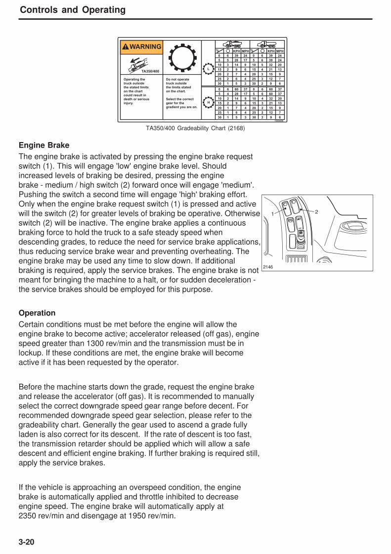
3-20
Controls and Operating
Engine Brake
The engine brake is activated by pressing the engine brake request
switch (1). This will engage 'low' engine brake level. Should
increased levels of braking be desired, pressing the engine
brake - medium / high switch (2) forward once will engage 'medium'.
Pushing the switch a second time will engage 'high' braking effort.
Only when the engine brake request switch (1) is pressed and active
will the switch (2) for greater levels of braking be operative. Otherwise
switch (2) will be inactive. The engine brake applies a continuous
braking force to hold the truck to a safe steady speed when
descending grades, to reduce the need for service brake applications,
thus reducing service brake wear and preventing overheating. The
engine brake may be used any time to slow down. If additional
braking is required, apply the service brakes. The engine brake is not
meant for bringing the machine to a halt, or for sudden deceleration -
the service brakes should be employed for this purpose.
Operation
Certain conditions must be met before the engine will allow the
engine brake to become active; accelerator released (off gas), engine
speed greater than 1300 rev/min and the transmission must be in
lockup. If these conditions are met, the engine brake will become
active if it has been requested by the operator.
Before the machine starts down the grade, request the engine brake
and release the accelerator (off gas). It is recommended to manually
select the correct downgrade speed gear range before decent. For
recommended downgrade speed gear selection, please refer to the
gradeability chart. Generally the gear used to ascend a grade fully
laden is also correct for its descent. If the rate of descent is too fast,
the transmission retarder should be applied which will allow a safe
descent and efficient engine braking. If further braking is required still,
apply the service brakes.
If the vehicle is approaching an overspeed condition, the engine
brake is automatically applied and throttle inhibited to decrease
engine speed. The engine brake will automatically apply at
2350 rev/min and disengage at 1950 rev/min.
TA350/400 Gradeability Chart (2168)
2146
WARNING
15354036
L
H
% %KPH MPH KPH MPH
TA350/400
0 6 39 24 0 6 39 24
0 6 60 37 0 6 60 37
5 4 28 17 5 6 60 37
5 5 28 17 5 6 39 24
20 2 7 4 20 3 15 9
25 2 6 4 25 3 12 7
15 2 9 6 15 4 21 13
10 3 14 9 10 5 32 20
30 1 5 3 30 2 9 6
15 2 9 6 15 3 21 13
25 1 6 4 25 2 12 7
20 1 7 4 20 2 15 9
30 1 5 3 30 2 9 6
Operating the
truck outside
the stated limits
on the chart
could result in
death or serious
injury.
Do not operate
truck outside
the limits stated
on the chart.
Select the correct
gear for the
gradient you are on.
10 2 14 9 10 4 32 20
1 2
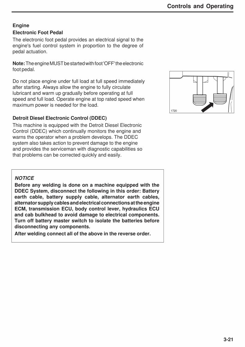
3-21
Controls and Operating
Engine
Electronic Foot Pedal
The electronic foot pedal provides an electrical signal to the
engine's fuel control system in proportion to the degree of
pedal actuation.
Note: The engine MUST be started with foot 'OFF' the electronic
foot pedal.
Do not place engine under full load at full speed immediately
after starting. Always allow the engine to fully circulate
lubricant and warm up gradually before operating at full
speed and full load. Operate engine at top rated speed when
maximum power is needed for the load.
Detroit Diesel Electronic Control (DDEC)
This machine is equipped with the Detroit Diesel Electronic
Control (DDEC) which continually monitors the engine and
warns the operator when a problem develops. The DDEC
system also takes action to prevent damage to the engine
and provides the serviceman with diagnostic capabilities so
that problems can be corrected quickly and easily.
1720
NOTICE
Before any welding is done on a machine equipped with theDDEC System, disconnect the following in this order: Batteryearth cable, battery supply cable, alternator earth cables,alternator supply cables and electrical connections at the engineECM, transmission ECU, body control lever, hydraulics ECUand cab bulkhead to avoid damage to electrical components.
Turn off battery master switch to isolate the batteries before
disconnecting any components.
After welding connect all of the above in the reverse order.
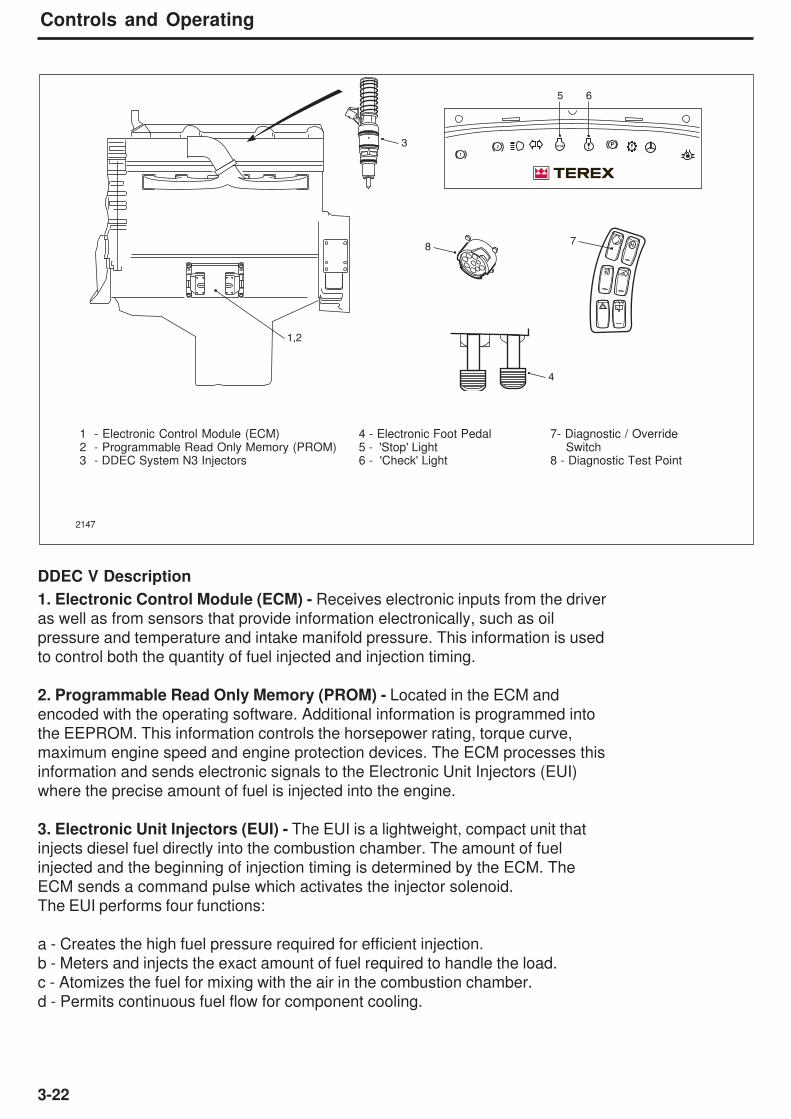
3-22
Controls and Operating
DDEC V Description
1. Electronic Control Module (ECM) - Receives electronic inputs from the driver
as well as from sensors that provide information electronically, such as oil
pressure and temperature and intake manifold pressure. This information is used
to control both the quantity of fuel injected and injection timing.
2. Programmable Read Only Memory (PROM) - Located in the ECM and
encoded with the operating software. Additional information is programmed into
the EEPROM. This information controls the horsepower rating, torque curve,
maximum engine speed and engine protection devices. The ECM processes this
information and sends electronic signals to the Electronic Unit Injectors (EUI)
where the precise amount of fuel is injected into the engine.
3. Electronic Unit Injectors (EUI) - The EUI is a lightweight, compact unit that
injects diesel fuel directly into the combustion chamber. The amount of fuel
injected and the beginning of injection timing is determined by the ECM. The
ECM sends a command pulse which activates the injector solenoid.
The EUI performs four functions:
a - Creates the high fuel pressure required for efficient injection.
b - Meters and injects the exact amount of fuel required to handle the load.
c - Atomizes the fuel for mixing with the air in the combustion chamber.
d - Permits continuous fuel flow for component cooling.
1 - Electronic Control Module (ECM) 4 - Electronic Foot Pedal 7- Diagnostic / Override2 - Programmable Read Only Memory (PROM) 5 - 'Stop' Light Switch3 - DDEC System N3 Injectors 6 - 'Check' Light 8 - Diagnostic Test Point
2147
PSTOP
1
2
H
5
78
4
1,2
3
6
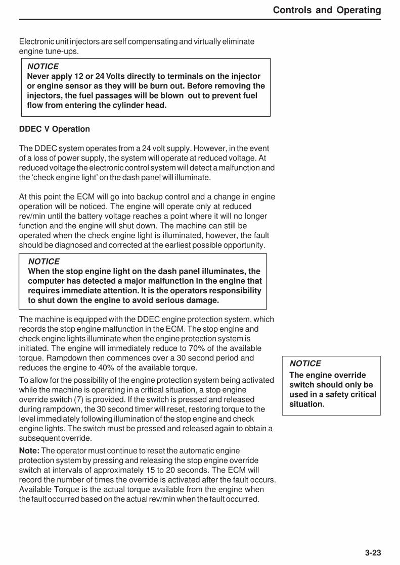
3-23
Controls and Operating
Electronic unit injectors are self compensating and virtually eliminate
engine tune-ups.
DDEC V Operation
The DDEC system operates from a 24 volt supply. However, in the event
of a loss of power supply, the system will operate at reduced voltage. At
reduced voltage the electronic control system will detect a malfunction and
the ‘check engine light’ on the dash panel will illuminate.
At this point the ECM will go into backup control and a change in engine
operation will be noticed. The engine will operate only at reduced
rev/min until the battery voltage reaches a point where it will no longer
function and the engine will shut down. The machine can still be
operated when the check engine light is illuminated, however, the fault
should be diagnosed and corrected at the earliest possible opportunity.
The machine is equipped with the DDEC engine protection system, which
records the stop engine malfunction in the ECM. The stop engine and
check engine lights illuminate when the engine protection system is
initiated. The engine will immediately reduce to 70% of the available
torque. Rampdown then commences over a 30 second period and
reduces the engine to 40% of the available torque.
To allow for the possibility of the engine protection system being activated
while the machine is operating in a critical situation, a stop engine
override switch (7) is provided. If the switch is pressed and released
during rampdown, the 30 second timer will reset, restoring torque to the
level immediately following illumination of the stop engine and check
engine lights. The switch must be pressed and released again to obtain a
subsequent override.
Note: The operator must continue to reset the automatic engine
protection system by pressing and releasing the stop engine override
switch at intervals of approximately 15 to 20 seconds. The ECM will
record the number of times the override is activated after the fault occurs.
Available Torque is the actual torque available from the engine when
the fault occurred based on the actual rev/min when the fault occurred.
NOTICE
The engine overrideswitch should only be
used in a safety critical
situation.
NOTICE
Never apply 12 or 24 Volts directly to terminals on the injector
or engine sensor as they will be burn out. Before removing the
injectors, the fuel passages will be blown out to prevent fuel
flow from entering the cylinder head.
NOTICE
When the stop engine light on the dash panel illuminates, thecomputer has detected a major malfunction in the engine thatrequires immediate attention. It is the operators responsibilityto shut down the engine to avoid serious damage.

3-24
Controls and Operating
The operator of a
DDEC-equipped vehicle
must not attempt to use
or read a DDR of any
kind while the vehicle is
operating. Doing so can
result in loss of control,
which may cause
vehicle damage and
may result in personal
injury.
When engine or
electronics system
diagnosis is required on
a DDEC-equippedvehicle, this must bedone by a person otherthan the operator. Theoperator must maintaincontrol of the movingvehicle while theassistant performs thediagnosis.
The engine should not be restarted after it has been shut down after
activation of the engine protection system unless the problem has
been diagnosed and corrected.
Conditions that will cause the Stop Engine Light to come on are; Low
Coolant Level, High Coolant Temperature, Low Oil Pressure and
High Oil Temperature.
Whenever the check engine light or stop engine light comes on, the
DDEC computer will determine where the problem is and will store
this information in its memory. If the malfunction is intermittent, the
lights will come on and go off as the computer senses the changing
engine condition.
A special diagnostic data reader (DDR) or laptop based Detroit
Diesel Diagnostic Link (DDDL) are available that can be plugged
into the engine computer memory to extract information related to the
cause of the problem. Once the malfunction has been corrected, the
DDEC system will return the engine to normal operation. The DDR
and DDDL can distinguish between active codes and those stored in
the historic code memory. The malfunction code recorded in the
ECM memory will remain until it is erased by a technician.
When the engine is not running and the ignition is on, or, the engine
is idling and not in an engine protection condition, engine faults can
be diagnosed by the operator. Pressing and releasing the diagnostic
request switch will cause the check engine light or stop engine light
to flash a code number indicating the fault, e.g. flash twice - pause -
flash five times - pause indicates a code 25. Code 25 indicates all
systems are operating correctly. Pressing the switch a second time
will stop the engine codes flashing. Refer to 'DDEC V Diagnostic
Codes' table for other code descriptions.
Note: Only one light will be flashing at any one time. When code flashing
is initiated, the active codes (or code 25) will be flashed on the stop
engine light, then the inactive codes (or code 25) will be flashed on the
check engine light. When all of the inactive codes have been flashed,
the process of flashing the codes will repeat until the conditions for
code flashing are no longer satisfied.
1 FLASH
SHORT
PAUSE
½ SEC
SHORT
PAUSE
½ SEC
LONG
PAUSE
3 SEC
CODE 13
ACTIVE
CODE 21
INACTIVE
3 FLASHES 2 FLASHES 1 FLASH
RED - SEL YELLOW - CEL
Flash code example 1792
2148
H

3-25
Controls and Operating
DDEC V DIAGNOSTIC CODES
DDEC Code
# (Flashed) PID SID FMI DDEC Description
- 240 - 2 Fram checksum incorrect
- 251 - 10 Clock module abnormal rate
- 251 - 13 Clock module fault/failure
- - 253 13 Incompatible calibration version
- - 254 0 External failed RAM
- - 254 1 Internal failed RAM
- - 254 6 Entered boot via switches
11 187 - 4 VSG sensor voltage low
11 187 - 7 VSG switch system not responding
12 187 - 3 VSG sensor high
13 111 - 4 Coolant level sensor input voltage low
13 111 - 6 Add coolant level sensor input voltage low
14 110 - 3 Coolant temperature sensor input voltage high
14 175 - 3 Oil temperature sensor input voltage high
15 110 - 4 Coolant temperature sensor input voltage low
15 175 - 4 Oil temperature sensor input voltage low
16 111 - 3 Coolant level sensor input voltage high
16 111 - 5 Add coolant level sensor input voltage high
21 91 - 3 TPS input voltage high
22 91 - 4 TPS input voltage low
23 174 - 3 Fuel temperature sensor input voltage high
24 174 - 4 Fuel temperature sensor input voltage low
25 - - - Reserved for 'No Codes'
26 - 25 1 Auxiliary shutdown #1 active
26 - 61 11 Auxiliary shutdown #2 active
27 171 - 3 Ambient air temperature sensor input voltage high
(Release 2.00 or later only)
27 172 - 3 Air temperature sensor input voltage high
27 105 - 3 Intake manifold temperature sensor input voltage high
28 171 - 4 Ambient air temperature circuit failed low
(Release 2.00 or later only)
28 172 - 4 Air temperature sensor input voltage low
28 105 - 4 Intake manifold temperature sensor input voltage low
31 - 51 3 Aux. output #3 open circuit (high side) (E-49)
31 - 51 4 Aux. output #3 short to ground (high side) (E-49)
31 - 51 7 Aux. output #3 mechanical system fail (E-49)
31 - 52 3 Aux. output #4 open circuit (high side) (E-48)
31 - 52 4 Aux. output #4 short to ground (high side) (E-48)
31 - 52 7 Aux. output #4 mechanical system fail (E-48)
32 - 238 4 SEL open circuit
32 - 238 3 SEL short to battery (+)
32 - 239 3 CEL short to battery (+)
32 - 239 4 CEL open circuit
33 102 - 3 Turbo boost pressure sensor input voltage high
34 102 - 4 Turbo boost pressure sensor input voltage low
35 100 - 3 Oil pressure sensor input voltage high
36 100 - 4 Oil pressure sensor input voltage low
37 94 - 3 Fuel pressure sensor input voltage high
37 95 - 3 Fuel restriction sensor input voltage high
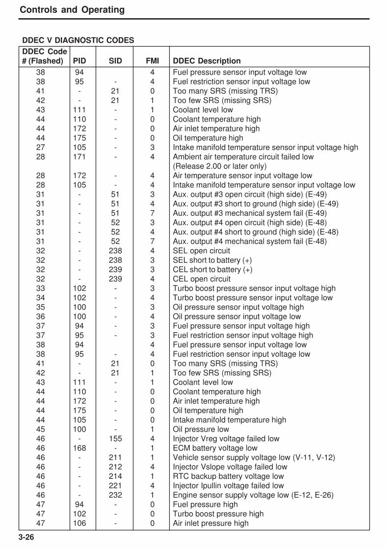
3-26
Controls and Operating
DDEC V DIAGNOSTIC CODES
DDEC Code
# (Flashed) PID SID FMI DDEC Description
38 94 4 Fuel pressure sensor input voltage low
38 95 - 4 Fuel restriction sensor input voltage low
41 - 21 0 Too many SRS (missing TRS)
42 - 21 1 Too few SRS (missing SRS)
43 111 - 1 Coolant level low
44 110 - 0 Coolant temperature high
44 172 - 0 Air inlet temperature high
44 175 - 0 Oil temperature high
27 105 - 3 Intake manifold temperature sensor input voltage high
28 171 - 4 Ambient air temperature circuit failed low
(Release 2.00 or later only)
28 172 - 4 Air temperature sensor input voltage low
28 105 - 4 Intake manifold temperature sensor input voltage low
31 - 51 3 Aux. output #3 open circuit (high side) (E-49)
31 - 51 4 Aux. output #3 short to ground (high side) (E-49)
31 - 51 7 Aux. output #3 mechanical system fail (E-49)
31 - 52 3 Aux. output #4 open circuit (high side) (E-48)
31 - 52 4 Aux. output #4 short to ground (high side) (E-48)
31 - 52 7 Aux. output #4 mechanical system fail (E-48)
32 - 238 4 SEL open circuit
32 - 238 3 SEL short to battery (+)
32 - 239 3 CEL short to battery (+)
32 - 239 4 CEL open circuit
33 102 - 3 Turbo boost pressure sensor input voltage high
34 102 - 4 Turbo boost pressure sensor input voltage low
35 100 - 3 Oil pressure sensor input voltage high
36 100 - 4 Oil pressure sensor input voltage low
37 94 - 3 Fuel pressure sensor input voltage high
37 95 - 3 Fuel restriction sensor input voltage high
38 94 4 Fuel pressure sensor input voltage low
38 95 - 4 Fuel restriction sensor input voltage low
41 - 21 0 Too many SRS (missing TRS)
42 - 21 1 Too few SRS (missing SRS)
43 111 - 1 Coolant level low
44 110 - 0 Coolant temperature high
44 172 - 0 Air inlet temperature high
44 175 - 0 Oil temperature high
44 105 - 0 Intake manifold temperature high
45 100 - 1 Oil pressure low
46 - 155 4 Injector Vreg voltage failed low
46 168 - 1 ECM battery voltage low
46 - 211 1 Vehicle sensor supply voltage low (V-11, V-12)
46 - 212 4 Injector Vslope voltage failed low
46 - 214 1 RTC backup battery voltage low
46 - 221 4 Injector Ipullin voltage failed low
46 - 232 1 Engine sensor supply voltage low (E-12, E-26)
47 94 - 0 Fuel pressure high
47 102 - 0 Turbo boost pressure high
47 106 - 0 Air inlet pressure high
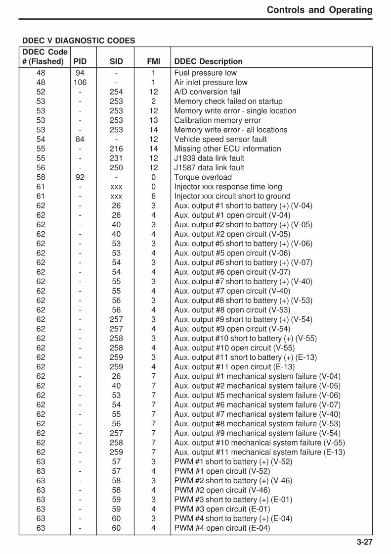
3-27
Controls and Operating
DDEC V DIAGNOSTIC CODES
DDEC Code
# (Flashed) PID SID FMI DDEC Description
48 94 - 1 Fuel pressure low
48 106 - 1 Air inlet pressure low
52 - 254 12 A/D conversion fail
53 - 253 2 Memory check failed on startup
53 - 253 12 Memory write error - single location
53 - 253 13 Calibration memory error
53 - 253 14 Memory write error - all locations
54 84 - 12 Vehicle speed sensor fault
55 - 216 14 Missing other ECU information
55 - 231 12 J1939 data link fault
56 - 250 12 J1587 data link fault
58 92 - 0 Torque overload
61 - xxx 0 Injector xxx response time long
61 - xxx 6 Injector xxx circuit short to ground
62 - 26 3 Aux. output #1 short to battery (+) (V-04)
62 - 26 4 Aux. output #1 open circuit (V-04)
62 - 40 3 Aux. output #2 short to battery (+) (V-05)
62 - 40 4 Aux. output #2 open circuit (V-05)
62 - 53 3 Aux. output #5 short to battery (+) (V-06)
62 - 53 4 Aux. output #5 open circuit (V-06)
62 - 54 3 Aux. output #6 short to battery (+) (V-07)
62 - 54 4 Aux. output #6 open circuit (V-07)
62 - 55 3 Aux. output #7 short to battery (+) (V-40)
62 - 55 4 Aux. output #7 open circuit (V-40)
62 - 56 3 Aux. output #8 short to battery (+) (V-53)
62 - 56 4 Aux. output #8 open circuit (V-53)
62 - 257 3 Aux. output #9 short to battery (+) (V-54)
62 - 257 4 Aux. output #9 open circuit (V-54)
62 - 258 3 Aux. output #10 short to battery (+) (V-55)
62 - 258 4 Aux. output #10 open circuit (V-55)
62 - 259 3 Aux. output #11 short to battery (+) (E-13)
62 - 259 4 Aux. output #11 open circuit (E-13)
62 - 26 7 Aux. output #1 mechanical system failure (V-04)
62 - 40 7 Aux. output #2 mechanical system failure (V-05)
62 - 53 7 Aux. output #5 mechanical system failure (V-06)
62 - 54 7 Aux. output #6 mechanical system failure (V-07)
62 - 55 7 Aux. output #7 mechanical system failure (V-40)
62 - 56 7 Aux. output #8 mechanical system failure (V-53)
62 - 257 7 Aux. output #9 mechanical system failure (V-54)
62 - 258 7 Aux. output #10 mechanical system failure (V-55)
62 - 259 7 Aux. output #11 mechanical system failure (E-13)
63 - 57 3 PWM #1 short to battery (+) (V-52)
63 - 57 4 PWM #1 open circuit (V-52)
63 - 58 3 PWM #2 short to battery (+) (V-46)
63 - 58 4 PWM #2 open circuit (V-46)
63 - 59 3 PWM #3 short to battery (+) (E-01)
63 - 59 4 PWM #3 open circuit (E-01)
63 - 60 3 PWM #4 short to battery (+) (E-04)
63 - 60 4 PWM #4 open circuit (E-04)

3-28
Controls and Operating
DDEC V DIAGNOSTIC CODES
DDEC Code
# (Flashed) PID SID FMI DDEC Description
63 - 267 3 PWM #5 short to battery (+) (E-08)
63 - 267 4 PWM #5 open circuit (E-08)
63 - 268 3 PWM #6 short to battery (+) (E-11)
63 - 268 4 PWM #6 open circuit (E-11)
63 - 57 0 PWM #1 above normal range (V-52)
63 - 57 1 PWM #1 below normal range (V-52)
63 - 58 0 PWM #2 above normal range (V-46)
63 - 58 1 PWM #2 below normal range (V-46)
63 - 59 0 PWM #3 above normal range (E-01)
63 - 59 1 PWM #3 below normal range (E-01)
63 - 60 0 PWM #4 above normal range (E-04)
63 - 60 1 PWM #4 below normal range (E-04)
63 - 267 0 PWM #5 above normal range (E-08)
63 - 267 1 PWM #5 below normal range (E-08)
63 - 268 0 PWM #6 above normal range (E-11)
63 - 268 1 PWM #6 below normal range (E-11)
63 - 57 7 PWM #1 mechanical system failure (V-52)
63 - 58 7 PWM #2 mechanical system failure (V-46)
63 - 59 7 PWM #3 mechanical system failure (E-01)
63 - 60 7 PWM #4 mechanical system failure (E-04)
63 - 267 7 PWM #5 mechanical system failure (E-08)
63 - 268 7 PWM #6 mechanical system failure (E-11)
64 103 - 8 Turbo speed sensor input failure
64 103 - 0 Turbo overspeed
65 107 - 3 Air filter restriction sensor voltage high
65 107 - 4 Air filter restriction sensor voltage low
66 - 99 3 Oil filter restriction sensor voltage high
66 - 99 4 Oil filter restriction sensor voltage low
67 109 - 3 Coolant pressure sensor input voltage high
67 109 - 4 Coolant pressure sensor input voltage low
67 106 - 3 Air inlet pressure sensor input voltage high
67 106 - 4 Air inlet pressure sensor input voltage low
68 - 230 6 TPS idle validation circuit fault (short to ground)
68 - 230 5 TPS idle validation circuit fault (open circuit)
71 - xxx 1 Injector xxx response time short
72 84 - 0 Vehicle overspeed
72 84 - 11 Vehicle overspeed (absolute)
73 107 - 0 Air filter restriction high
74 99 - 0 Oil filter restriction high
75 - 155 3 Injector Vreg voltage failed high
75 168 - 0 ECM battery voltage high
75 - 211 0 Vehicle sensor supply voltage failed high (V-11, V-12)
75 - 212 3 Injector Vslope voltage failed high
75 - 214 0 RTC backup battery voltage high
75 - 221 3 Injector Ipullin voltage failed high
75 - 232 0 Engine sensor supply voltage high (E-12, E-26)
76 121 - 0 Engine overspeed with engine brake
77 21 - 0 ECU temperature above range
77 21 - 1 ECU temperature below range

3-29
Controls and Operating
DDEC V DIAGNOSTIC CODES
DDEC Code
# (Flashed) PID SID FMI DDEC Description
77 21 - 3 ECU temperature failed high
77 21 - 4 ECU temperature failed low
77 100 - 0 Oil pressure high
77 102 - 1 Turbo boost pressure low
77 108 - 0 Barometric pressure high
77 108 - 1 Barometric pressure low
77 171 - 0 Ambient air temperature high
77 171 - 1 Ambient air temperature low
77 174 - 0 Fuel temp high
77 251 - 10 Clock incorrect
77 251 - 13 Clock failure
77 252 - 10 Date incorrect
77 252 - 13 Clock/Date failure
81 98 - 3 Oil level sensor input voltage high
81 173 - 3 Exhaust temperature sensor input voltage high
82 98 - 4 Oil level sensor input voltage low
82 173 - 4 Exhaust temperature sensor input voltage low
83 173 - 0 Exhaust temperature high
83 173 - 4 Exhaust temperature sensor input voltage low
83 73 - 0 Pump pressure high
84 98 - 1 Oil level low
85 190 - 0 Engine overspeed
86 73 - 3 Pump pressure sensor input voltage high
86 108 - 3 Barometric pressure sensor input voltage high
87 73 - 4 Pump pressure sensor input voltage low
87 108 - 4 Barometric pressure sensor input voltage low
88 109 - 1 Coolant pressure low
89 95 - 0 Fuel restriction high
89 111 - 12 Maintenance alert coolant level fault

3-30
Controls and Operating
Allison Series 4000 Automatic Shift Transmission
The Allison Series 4000 transmission is equipped with an electronic
control unit (ECU) which continually monitors the transmission and
shift system electrical components and warns the operator when a
problem develops. It also takes action to prevent damage to the
transmission, and provides the serviceman with diagnostic
capabilities so that problems can be corrected quickly and easily.
When a fault occurs, the 'check transmission' lamp will illuminate and
an error code will be generated. The error code can be accessed
through the 4th GEN gearshift lever. The error code is also recorded
in the transmission ECU, and can be accessed by the serviceman by
plugging in a data reader to extract information relating to the fault.
The error code recorded in the ECU memory will remain until it is
erased by a technician.
If a major fault is detected, it is the operators responsibility to shut
down the machine as soon as it is safe to do so. The machine should
not be restarted until the fault has been diagnosed and corrected.
Refer to 'Transmission 4th GEN control fault codes' table for a list of
fault codes (page 3-34 to 3-36).
The Series 4000 transmission with 4th GEN control has been
designed to provide the driver with six forward gears, one reverse
gear and a neutral position. The gear position is indicated by the LCD
display on the gearshift lever. The transmission is full automatic
control.
Before any welding is
done on a machine
equipped with 4th GEN
control shift system,
disconnect the following
in this order: Battery earth
cable, battery supply
cable, alternator earth
cables, alternator supply
cables and electrical
connections at the engine
ECM, transmission ECU,
hydraulic ECU, VDU ECU
and cab bulkhead to
avoid damage to electrical
components. Turn off
battery master switch toisolate the bateries beforedisconnecting anycomponents.After welding connect allof the above in reverseorder.
NOTICE

3-31
Controls and Operating
4th GEN Shift Controller
The 4th GEN shift controller has 6 forward ranges and 1 reverse
range as well as a neutral position.
The shift selector has a two digit LED display, that during normal
operation will display the range selected and the range attained.
Diagnostic information can be displayed on the two digit LED display
by pressing the diagnostic mode button. There is a hold override
button on the lever that must be pressed when shifting between
Drive (D), Neutral (N) and Reverse (R). The hold override button is
released when the desired selector position is reached. The selector
can move between Drive (D) and the number of ranges without
pressing the hold override button.
The transmission upshifts and downshifts automatically between first
range and the highest range selected on the range selector in direct
response to the throttle position and transmission output speed.
When reverse range is selected the 'Reverse alarm' sounds and the
'Reverse light' illuminates to warn personnel at the rear of the
machine that reverse gear has been selected.
When drive (D) is selected, the transmission automatically upshifts
and downshifts through all six forward ranges as required by loads
and travel speeds. Selecting a lower range (4th, 3rd etc.) limits the
highest range to which the transmission will automatically upshift. If a
lower range is selected while moving forward, the transmission
automatically downshifts sequentially to the selected lower range at
maximum controlled engine speeds. Downshifts will not occur until
machine is slowed by use of the service brakes and/or retarder.
When shifting from neutral to start from a standstill, or to reverse
direction, decelerate the engine to idle speed. To move forward,
select Drive (D) and accelerate the engine to the machine load and
speed requirements. The transmission will automatically upshift from
1st through 6th ranges as travel speed increases.
With the throttle fully depressed, and the Mode Button in the 'POWER'
(primary shift schedule) position, the transmission upshifts to the next
higher range when the engine attains maximum rated speed, since
maximum power train output is needed under this condition. At lower
throttle settings where minimum power train performance is required,
the transmission will upshift to the next higher range at less than
maximum rated engine speed.
Upgrades or soft spots might slow travel speed, even at full throttle,
requiring transmission downshifts to maintain maximum powertrain
performance. When this occurs, the transmission downshifts
automatically.
MO
DE
SELECT
MONIT
OR
1 2 3 4 5 D N R
3
1
2
45
1793
1. Hold override 4. Range attained
2. Mode button 5. Display mode
3. Range selected button
Do not allow the vehicle to
coast in Neutral. This
practice can result in
severe transmission
damage.
NOTICE
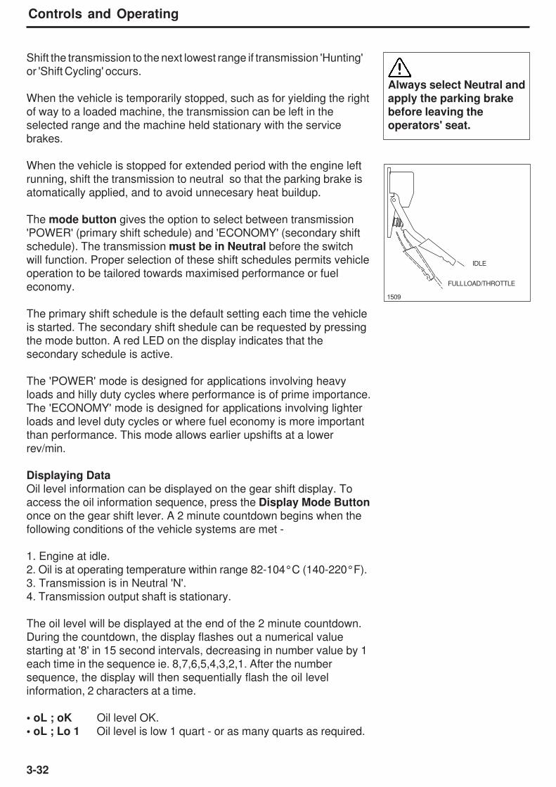
3-32
Controls and Operating
Shift the transmission to the next lowest range if transmission 'Hunting'
or 'Shift Cycling' occurs.
When the vehicle is temporarily stopped, such as for yielding the right
of way to a loaded machine, the transmission can be left in the
selected range and the machine held stationary with the service
brakes.
When the vehicle is stopped for extended period with the engine left
running, shift the transmission to neutral so that the parking brake is
atomatically applied, and to avoid unnecesary heat buildup.
The mode button gives the option to select between transmission
'POWER' (primary shift schedule) and 'ECONOMY' (secondary shift
schedule). The transmission must be in Neutral before the switch
will function. Proper selection of these shift schedules permits vehicle
operation to be tailored towards maximised performance or fuel
economy.
The primary shift schedule is the default setting each time the vehicle
is started. The secondary shift shedule can be requested by pressing
the mode button. A red LED on the display indicates that the
secondary schedule is active.
The 'POWER' mode is designed for applications involving heavy
loads and hilly duty cycles where performance is of prime importance.
The 'ECONOMY' mode is designed for applications involving lighter
loads and level duty cycles or where fuel economy is more important
than performance. This mode allows earlier upshifts at a lower
rev/min.
Displaying Data
Oil level information can be displayed on the gear shift display. To
access the oil information sequence, press the Display Mode Buttononce on the gear shift lever. A 2 minute countdown begins when the
following conditions of the vehicle systems are met -
1. Engine at idle.
2. Oil is at operating temperature within range 82-104°C (140-220°F).
3. Transmission is in Neutral 'N'.
4. Transmission output shaft is stationary.
The oil level will be displayed at the end of the 2 minute countdown.
During the countdown, the display flashes out a numerical value
starting at '8' in 15 second intervals, decreasing in number value by 1
each time in the sequence ie. 8,7,6,5,4,3,2,1. After the number
sequence, the display will then sequentially flash the oil level
information, 2 characters at a time.
• oL ; oK Oil level OK.
• oL ; Lo 1 Oil level is low 1 quart - or as many quarts as required.
Always select Neutral and
apply the parking brake
before leaving the
operators' seat.
1509
IDLE
FULL LOAD/THROTTLE
3-33
Controls and Operating
Note: Failure to meet any of the previous conditions 1-4, will stop the
2 minute countdown. The gear shifter will display one of the following
codes -
• oL0X : Setting time too short • oLTL : Sump fluid temp too low
• oLEL : Engine RPM too low • oLTH : Sump fluid temp too high
• oLEH : Engine RPM too high • oLSH : Output shaft rotation
detected
• oLSN : Neutral not selected • oLFL : Sensor failed
Displaying Diagnostic Fault CodesDiagnostic codes can be displayed on the gear shift lever display. To
access the diagnostic code sequence, press the Display Modebutton twice on the gear shifter. Each code consists of 4 sequential
elements; each being either 1 or 2 characters. The display for each
code will repeat continuously until the next code is displayed (if
present). To display the next code if present, press the mode button.
The following cycle illustrates the display cycle:
• d1 Code list position (d1 newest, d5 oldest)
• P• 27• 14
• Code repeats until the next code (d2) is accessed by pressing the
mode button
Clearing Diagnostic Codes• To clear active codes, press and hold mode button for 3 to 5
seconds.
• To clear inactive codes, press and hold mode button for 8 to 10
seconds.
Exiting Diagnostic ModeAny of the following methods may be used to exit the diagnostic
display mode:
• Momentarily press the display mode button.
• Move the gear shift lever to any other position than the one
selected when the diagnostic display mode was activated.
• Wait until time out (approx. 10 minutes). The system automatically
returns to normal operating mode.
• Turn off the vehicle - illuminating power to transmission ECU.
• oL ; HI 1 Oil level is high 1 quart - or as many quarts overfilled.
(1 US quart = 0.95 litre = 0.2 gallon)

3-34
Controls and Operating
C1312 Retarder Request Sensor Failed Low
C1313 Retarder Request Sensor Failed High
P0122 Pedal Position Sensor Circuit Low Voltage
P0123 Pedal Position Sensor Circuit High Voltage
P0218 Transmission Fluid Over temperature
P0561 System Voltage Low Performance
P0562 System Voltage Low
P0563 System Voltage High
P0602 TCM Not Programmed
P0610 TCM Vehicle Options Error (Trans ID)
P0613 TCM Processor
P0614 Torque Control Mismatch (ECM/ TCM)
P0634 TCM Internal Temperature Too High
P063E Auto Configuration Throttle Input Not Present
P063F Auto Configuration Engine Coolant Temperature Input Not
Present
P0658 Actuator Supply Voltage 1 Low (HSD 1 open/gnd)
P0659 Actuator Supply Voltage 1 High (HSD 1 batt)
P0701 Transmission Control System Performance
P0702 Transmission Control System Electrical (Trans ID)
P0703 Brake Switch Circuit
P0708 Transmission Range Sensor Circuit - High Input
P070C Transmission Fluid Level Sensor Circuit - Low Input
P070D Transmission Fluid Level Sensor Circuit - High Input
P0711 Transmission Fluid Temp. Sensor Circuit Performance
P0712 Transmission Fluid Temperature Sensor Circuit Low Input
P0713 Transmission Fluid Temperature Sensor Circuit High Input
P0716 Turbine Speed Sensor Circuit Performance
P0717 Turbine Speed Sensor Circuit No Signal
P071D General Purpose Input Fault
P071A RELS Input Failed On
P0720 Output Speed Sensor Circuit
P0721 Output Speed Sensor Circuit Performance
P0722 Output Speed Sensor Circuit No Signal
P0726 Engine Speed Input Circuit Performance
P0727 Engine Speed Input Circuit No Signal
P0729 Incorrect 6th Gear Ratio
P0730 Incorrect Gear Ratio
P0731 Incorrect 1st Gear Ratio
P0732 Incorrect 2nd Gear Ratio
P0733 Incorrect 3rd Gear Ratio
P0734 Incorrect 4th Gear Ratio
P0735 Incorrect 5th Gear Ratio
Code Meaning of code / Possible Cause of Fault
Allison 4th GEN Diagnostic Codes
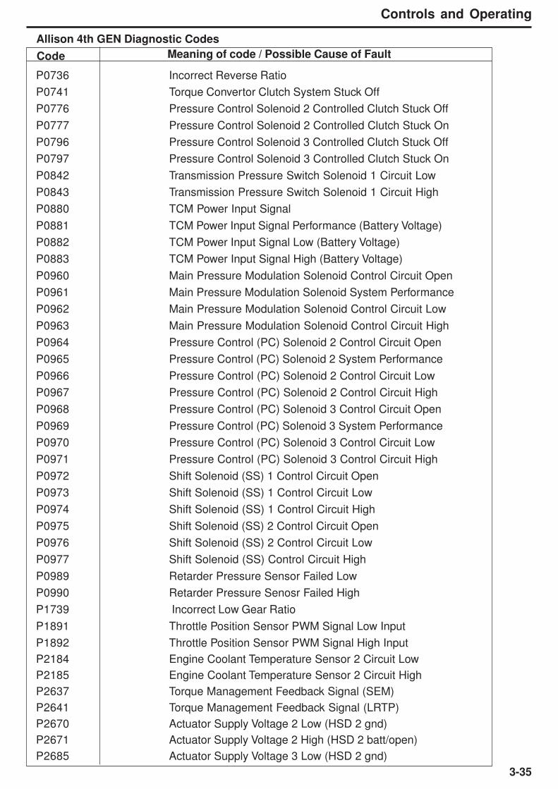
3-35
Controls and Operating
P0736 Incorrect Reverse Ratio
P0741 Torque Convertor Clutch System Stuck Off
P0776 Pressure Control Solenoid 2 Controlled Clutch Stuck Off
P0777 Pressure Control Solenoid 2 Controlled Clutch Stuck On
P0796 Pressure Control Solenoid 3 Controlled Clutch Stuck Off
P0797 Pressure Control Solenoid 3 Controlled Clutch Stuck On
P0842 Transmission Pressure Switch Solenoid 1 Circuit Low
P0843 Transmission Pressure Switch Solenoid 1 Circuit High
P0880 TCM Power Input Signal
P0881 TCM Power Input Signal Performance (Battery Voltage)
P0882 TCM Power Input Signal Low (Battery Voltage)
P0883 TCM Power Input Signal High (Battery Voltage)
P0960 Main Pressure Modulation Solenoid Control Circuit Open
P0961 Main Pressure Modulation Solenoid System Performance
P0962 Main Pressure Modulation Solenoid Control Circuit Low
P0963 Main Pressure Modulation Solenoid Control Circuit High
P0964 Pressure Control (PC) Solenoid 2 Control Circuit Open
P0965 Pressure Control (PC) Solenoid 2 System Performance
P0966 Pressure Control (PC) Solenoid 2 Control Circuit Low
P0967 Pressure Control (PC) Solenoid 2 Control Circuit High
P0968 Pressure Control (PC) Solenoid 3 Control Circuit Open
P0969 Pressure Control (PC) Solenoid 3 System Performance
P0970 Pressure Control (PC) Solenoid 3 Control Circuit Low
P0971 Pressure Control (PC) Solenoid 3 Control Circuit High
P0972 Shift Solenoid (SS) 1 Control Circuit Open
P0973 Shift Solenoid (SS) 1 Control Circuit Low
P0974 Shift Solenoid (SS) 1 Control Circuit High
P0975 Shift Solenoid (SS) 2 Control Circuit Open
P0976 Shift Solenoid (SS) 2 Control Circuit Low
P0977 Shift Solenoid (SS) Control Circuit High
P0989 Retarder Pressure Sensor Failed Low
P0990 Retarder Pressure Senosr Failed High
P1739 Incorrect Low Gear Ratio
P1891 Throttle Position Sensor PWM Signal Low Input
P1892 Throttle Position Sensor PWM Signal High Input
P2184 Engine Coolant Temperature Sensor 2 Circuit Low
P2185 Engine Coolant Temperature Sensor 2 Circuit High
P2637 Torque Management Feedback Signal (SEM)
P2641 Torque Management Feedback Signal (LRTP)
P2670 Actuator Supply Voltage 2 Low (HSD 2 gnd)
P2671 Actuator Supply Voltage 2 High (HSD 2 batt/open)
P2685 Actuator Supply Voltage 3 Low (HSD 2 gnd)
Code Meaning of code / Possible Cause of Fault
Allison 4th GEN Diagnostic Codes

3-36
Controls and Operating
P2686 Actuator Supply Voltage 3 High (HSD 3 batt/open)
P2714 Pressure Control Solenoid 4 Controlled Clutch Stuck Off
P2715 Pressure Control Solenoid 4 Controlled Clutch Stuck On
P2718 Pressure Control (PC) Solenoid 4 System Open
P2719 Pressure Control (PC) Solenoid 4 System Performance
P2720 Pressure Control (PC) Solenoid 4 Control Circuit Low
P2721 Pressure Control (PC) Solenoid 4 Control Circuit High
P2723 Pressure Control Solenoid 1 Controlled Clutch Stuck Off
P2724 Pressure Control Solenoid 1 Controlled Clutch Stuck On
P2727 Pressure Control (PC) Solenoid 1 System Open
P2728 Pressure Control (PC) Solenoid 1 System Performance
P2729 Pressure Control (PC) Solenoid 1 Control Circuit Low
P2730 Pressure Control (PC) Solenoid 1 Control Circuit High
P2736 Pressure Control (PC) Solenoid 5 System Open
P2737 Pressure Control (PC) Solenoid 5 System Performance
P2738 Pressure Control (PC) Solenoid 5 Control Circuit Low
P2739 Pressure Control (PC) Solenoid 5 Control Circuit High
P2740 Retarder Oil Temperature Hot
P2742 Retarder Oil Temperature Sensor Circuit - Low Input
P2743 Retarder Oil Temperature Sensor Circuit - High Input
P2761 TCC PCS Control Circuit Open
P2762 TCC PCS Control Circuit Range/ Performance
P2763 TCC PCS Control Ciruit High
P2764 TCC PCS Control Circuit Low
P278A Kickdown Input Switch Circuit
P2793 Gear Shift Direction Circuit
P2808 Pressure Control Solenoid 6 Controlled Clutch Stuck Off
P2809 Pressure Control Solenoid 6 Controlled Clutch Stuck On
P2812 Pressure Control (PC) Solenoid 6 System Open
P2813 Pressure Control (PC) Solenoid 6 System Performance
P2814 Pressure Control (PC) Solenoid 6 Control Circuit Low
P2815 Pressure Control (PC) Solenoid 6 Control Circuit High
U0001 Hi Speed CAN Bus Reset Counter Overrun (CAN2/IES CAN)
U0010 CAN Bus Reset Counter Overrun (CAN1/J1939)
U0100 Lost Communication with ECM / PCM "A"
U0103 Lost Communication With Gear Shift Module 1
U0115 Lost Communication with ECM / PCM "B"
U0291 Lost Communication with Gear Shift Module 2
U0292 Invalid Data received from Gear Shift Control Module 2
U0304 Software Incompatability With Gear Shift Control Module 1
U0333 Software Incompatability With Gear Shift Control Module 2
U0404 Invalid Data received from Gear Shift Control Module 1
U0592 Invalid Data received from Gear Shift Control Module 2
Code Meaning of code / Possible Cause of Fault
Allison 4th GEN Diagnostic Codes
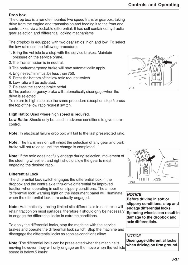
3-37
Controls and Operating
Drop box
The drop box is a remote mounted two speed transfer gearbox, taking
drive from the engine and transmission and feeding it to the front and
centre axles via a lockable differential. It has self contained hydraulic
gear selection and differential locking mechanisms.
The dropbox is equipped with two gear ratios; high and low. To select
the low ratio use the following procedure:
1. Bring the vehicle to a stop with the service brakes. Maintain
pressure on the service brake.
2.The Transmission is in neutral.
3.The park/emergency brake will now automatically apply.
4. Engine rev/min must be less than 750.
5. Press the bottom of the low ratio request switch.
6. Low ratio will be activated.
7. Release the service brake pedal.
8. The park/emergency brake will automatically disengage when the
drive is selected.
To return to high ratio use the same procedure except on step 5 press
the top of the low ratio request switch.
High Ratio: Used where high speed is required.
Low Ratio: Should only be used in adverse conditions to give more
control.
Note: In electrical failure drop box will fail to the last preselected ratio.
Note: The transmission will inhibit the selection of any gear and park
brake will not release until the change is completed.
Note: If the ratio does not fully engage during selection, movement of
the steering wheel left and right should allow the gear to mesh,
engaging the desired ratio.
Differential Lock
The differential lock switch engages the differential lock in the
dropbox and the centre axle thru-drive differential for improved
traction when operating in soft or slippery conditions. The amber
'differential lock' warning light on the instrument panel will illuminate
when the differential locks are actually engaged.
Note: Automatically - acting limited slip differentials in each axle will
retain traction on most surfaces, therefore it should only be necessary
to engage the differential locks in extreme conditions.
To apply the differential locks, stop the machine with the service
brakes and operate the differential lock switch. Stop the machine and
disengage the differential locks as soon as conditions allow.
Note: The diferential locks can be preselected when the machine is
moving however, they will only engage on the move when the vehicle
speed is below 5 km/hr.
2149
2150
NOTICE
Before driving in soft orslippery conditions, stop and
engage differential locks.Spinning wheels can result in
damage to the dropbox andaxle differentials.
NOTICE
Disengage differential locks
when driving on firm ground.
H
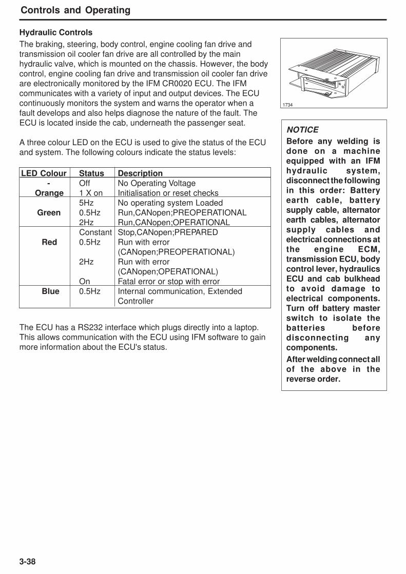
3-38
Controls and Operating
LED Colour Status Description
- Off No Operating Voltage
Orange 1 X on Initialisation or reset checks
5Hz No operating system Loaded
Green 0.5Hz Run,CANopen;PREOPERATIONAL
2Hz Run,CANopen;OPERATIONAL
Constant Stop,CANopen;PREPARED
Red 0.5Hz Run with error
(CANopen;PREOPERATIONAL)
2Hz Run with error
(CANopen;OPERATIONAL)
On Fatal error or stop with error
Blue 0.5Hz Internal communication, Extended
Controller
NOTICE
Before any welding is
done on a machine
equipped with an IFM
hydraulic system,
disconnect the following
in this order: Battery
earth cable, battery
supply cable, alternator
earth cables, alternatorsupply cables andelectrical connections atthe engine ECM,transmission ECU, bodycontrol lever, hydraulicsECU and cab bulkheadto avoid damage toelectrical components.Turn off battery masterswitch to isolate thebatteries beforedisconnecting anycomponents.
After welding connect all
of the above in thereverse order.
Hydraulic Controls
The braking, steering, body control, engine cooling fan drive and
transmission oil cooler fan drive are all controlled by the main
hydraulic valve, which is mounted on the chassis. However, the body
control, engine cooling fan drive and transmission oil cooler fan drive
are electronically monitored by the IFM CR0020 ECU. The IFM
communicates with a variety of input and output devices. The ECU
continuously monitors the system and warns the operator when a
fault develops and also helps diagnose the nature of the fault. The
ECU is located inside the cab, underneath the passenger seat.
A three colour LED on the ECU is used to give the status of the ECU
and system. The following colours indicate the status levels:
The ECU has a RS232 interface which plugs directly into a laptop.
This allows communication with the ECU using IFM software to gain
more information about the ECU's status.
1734

3-39
Controls and Operating
Steering
The steering wheel position can be adjusted as required for the most
convenient operating position. To adjust, pull out adjustment lock and
tilt steering wheel up or down as desired; release lever to lock
adjustment.
To steer the machine, rotate the steering wheel in the desired
direction to the required radius of turn. The machine will turn only as
the steering wheel is turned and at a rate of turning directly
proportional to steering wheel speed. The machine will stop and hold
position when the steering wheel is stopped. To return the machine to
the straight ahead position or to the opposite direction, turn the
steering wheel in the opposite direction.
1724
1725
Do not attempt to adjust the steering wheelwhile the machine is moving. Loss of controlmay result. Stop the machine; apply parkbrake; then carry out adjustments.

3-40
Controls and Operating
Body Control
This lever operates the body hoist cylinders. The three operating
positions of the lever are -
Raise - Pulling the lever back and holding in this position will raise the
body. When released, the lever will spring back to the 'neutral' position.
Neutral - If the body is above the body proximity switch, the lever in this
position will stop and hold the body at any desired height. If the body is
below the proximity switch, the ECU defaults the main hydraulic valve to
the float position. The body should be fully lowered and in the 'neutral'
position while the machine is in motion. The lever will remain in the
'neutral' position when released.
Power Down - Pushing the lever forward provides hydraulic force to
power down the body. Pushing the lever fully forward will engage the
electric detent. When the body reaches the proximity switch, the lever
springs back to the 'neutral' position and power down is ramped back to
allow a smooth transition to the float position.
1726
1512
NOTICE
The body must remain lowered with lever in the 'neutral'position until it is necessary to operate the body again. Failureto comply to this could result in overheating the hydraulic oiland failure of the hydraulic system components.
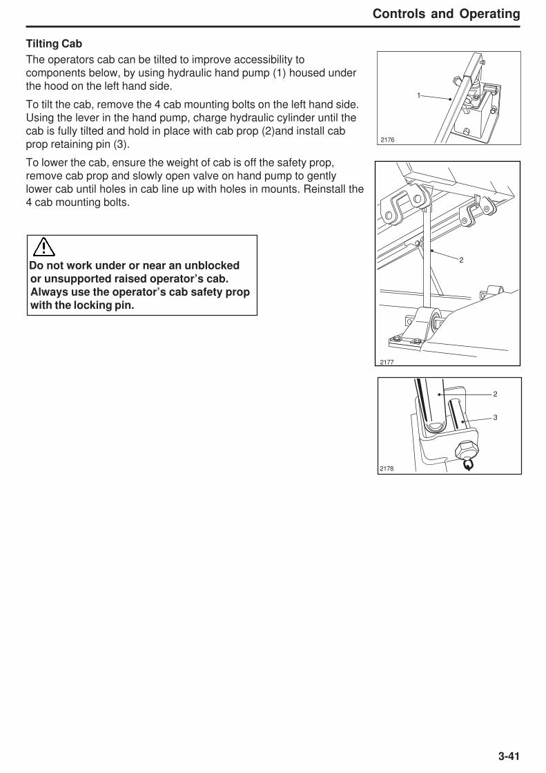
3-41
Controls and Operating
Tilting Cab
The operators cab can be tilted to improve accessibility to
components below, by using hydraulic hand pump (1) housed under
the hood on the left hand side.
To tilt the cab, remove the 4 cab mounting bolts on the left hand side.
Using the lever in the hand pump, charge hydraulic cylinder until the
cab is fully tilted and hold in place with cab prop (2)and install cab
prop retaining pin (3).
To lower the cab, ensure the weight of cab is off the safety prop,
remove cab prop and slowly open valve on hand pump to gently
lower cab until holes in cab line up with holes in mounts. Reinstall the
4 cab mounting bolts.
2176
2177
2178
Do not work under or near an unblocked
or unsupported raised operator’s cab.
Always use the operator’s cab safety propwith the locking pin.
2
1
2
3
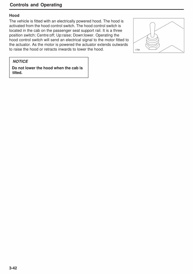
3-42
Controls and Operating
Hood
The vehicle is fitted with an electrically powered hood. The hood is
activated from the hood control switch. The hood control switch is
located in the cab on the passenger seat support rail. It is a three
position switch; Centre:off; Up:raise; Down:lower. Operating the
hood control switch will send an electrical signal to the motor fitted to
the actuator. As the motor is powered the actuator extends outwards
to raise the hood or retracts inwards to lower the hood. 1791
Do not lower the hood when the cab is
tilted.
NOTICE
4-1
Operating the Truck
4 - Operating the Truck

4-2
Operating the Truck
This Page Intentionally Left Blank
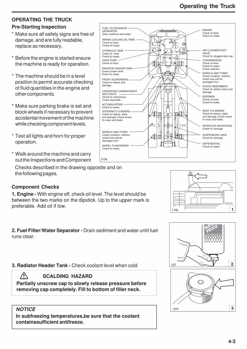
4-3
Operating the Truck
3. Radiator Header Tank - Check coolant level when cold.
Component Checks
1. Engine - With engine off, check oil level. The level should be
between the two marks on the dipstick. Up to the upper mark is
preferable. Add oil if low.
OPERATING THE TRUCK
Pre-Starting Inspection
* Make sure all safety signs are free of
damage, and are fully readable,
replace as necessary.
* Before the engine is started ensure
the machine is ready for operation.
* The machine should be in a level
position to permit accurate checking
of fluid quantities in the engine and
other components.
* Make sure parking brake is set and
block wheels if necessary to prevent
accidental movement of the machine
while checking component levels.
* Test all lights and horn for proper
operation.
* Walk around the machine and carry
out the Inspections and Component 2154
1748 1
1375 3
2. Fuel Filter/Water Separator - Drain sediment and water until fuel
runs clear.
037 2
NOTICE
In subfreezing temperatures,be sure that the coolant
containssufficient antifreeze.
SCALDING HAZARD
Partially unscrew cap to slowly release pressure before
removing cap completely. Fill to bottom of filler neck.
ENGINECheck oil level.Check for leaks
HYDRAULIC TANKCheck oil level.Check for leaks.
FRONT SUSPENSIONCheck for debris anddamage.
WHEEL PLANETARIESCheck for leaks.
ACCUMULATORSCheck for leaks.
DROPBOXCheck oil level.Check for leaks.
HAND PUMPCheck oil level.
STEERING CYLINDERSCheck for debris, leaksand damage. Check hoses for wear and leaks.
RADIATOR HEADER TANKCheck coolant level.Check for leaks.
OPERATORS COMPARTMENTAND STEPSCheck for cleanliness.Check seat belts.
SHOCK ABSORBERSCheck for debris, leaks anddamage.
WHEELS AND TYRESCheck condition, inflation, wheel nuts and for damaged rims.
WHEELS AND TYRESCheck condition, inflation, wheel nuts and for damaged rims.
TRANSMISSIONCheck oil level.Check for leaks.Check indicator.
FUEL FILTER/WATERSEPARATORDrain sediment and water.
AIR CLEANER DUST VALVECheck for plugged dust cap.
BODY CYLINDERSCheck for debris, leaksand damage. Check hosesfor wear and leaks.
INTERLEAF MOUNTINGSCheck for damage.
SUSPENSION LINKSCheck for damage.
DIFFERENTIALCheck for leaks.
BRAKE COOLING OIL TANK Check oil level.Check for leaks.
FS1212
Checks described in the drawing opposite and on
the following pages.
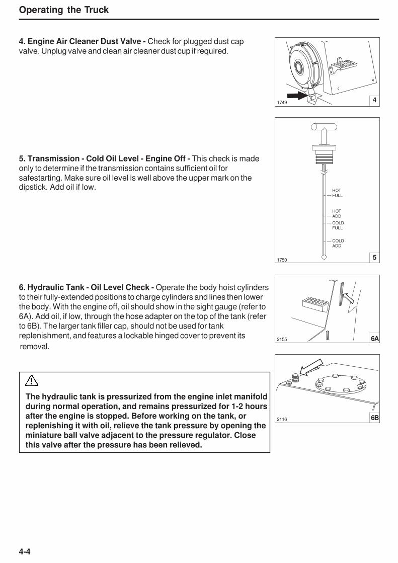
4-4
Operating the Truck
4. Engine Air Cleaner Dust Valve - Check for plugged dust cap
valve. Unplug valve and clean air cleaner dust cup if required.
1749 4
51750
2155 6A
5. Transmission - Cold Oil Level - Engine Off - This check is made
only to determine if the transmission contains sufficient oil for
safestarting. Make sure oil level is well above the upper mark on thedipstick. Add oil if low.
6. Hydraulic Tank - Oil Level Check - Operate the body hoist cylinders
to their fully-extended positions to charge cylinders and lines then lower
the body. With the engine off, oil should show in the sight gauge (refer to
6A). Add oil, if low, through the hose adapter on the top of the tank (refer
to 6B). The larger tank filler cap, should not be used for tank
replenishment, and features a lockable hinged cover to prevent its
removal.
The hydraulic tank is pressurized from the engine inlet manifoldduring normal operation, and remains pressurized for 1-2 hoursafter the engine is stopped. Before working on the tank, or
replenishing it with oil, relieve the tank pressure by opening the
miniature ball valve adjacent to the pressure regulator. Closethis valve after the pressure has been relieved.
COLD
ADD
COLD
FULL
HOT
FULL
HOT
ADD
2116 6B
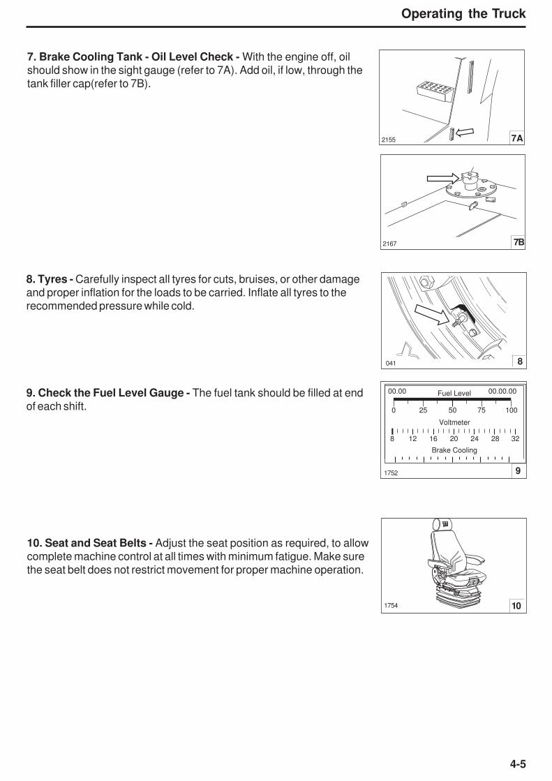
4-5
Operating the Truck
Fuel Level
Voltmeter
00.00 00.00.00
0
8 12 16 20 24 28 32
25 50 75 100
Brake Cooling
1754 10
8. Tyres - Carefully inspect all tyres for cuts, bruises, or other damage
and proper inflation for the loads to be carried. Inflate all tyres to the
recommended pressure while cold.
9. Check the Fuel Level Gauge - The fuel tank should be filled at end
of each shift.
10. Seat and Seat Belts - Adjust the seat position as required, to allow
complete machine control at all times with minimum fatigue. Make sure
the seat belt does not restrict movement for proper machine operation.
2167 7B
1752
8
7. Brake Cooling Tank - Oil Level Check - With the engine off, oil
should show in the sight gauge (refer to 7A). Add oil, if low, through the
tank filler cap(refer to 7B).
2155 7A
9
041

4-6
Operating the Truck
Engine Operation
Never start the engine indoors unless proper exhaust
ventilation is provided to remove deadly exhaust gases. Once
the engine is running, move the machine outdoors as soon
as possible. Exhaust gases are hazardous and can cause
unconsciousness and death.
NOTICE
Operating the engine beyond high idle speed can cause severe
engine damage. The engine speed must not exceed 2300 rev/
min under any circumstances. When descending a steepgrade, use a combination of transmission gears, retarder,engine brake and service brakes to control the vehicle and
engine speed.
NOTICE
Do not place engine under FULL LOAD at FULL SPEED
IMMEDIATELY after starting. ALWAYS allow the engine to fully
circulate lubricant and warm up gradually before operating at full
speed and full load.
Operate engine at top rated speed when maximum power isneeded for the load. Operation of the engine below top ratedspeed can occur during gear shifting due to the difference ofratios between transmission gears, but engine operation MUSTNOT be sustained more than 30 seconds at full throttle below toprated speed.
NEVER idle the engine for more than 5 minutes at a time; shut itoff.
If any gauge operates outwith its normal operating range, or awarning light illuminates, shut engine down immediately andreport to service or maintenance personnel.

4-7
Operating the Truck
Starting the Engine
Attention to the warning lights and instruments when starting the
engine, and operating, will help the operator to monitor the machine
systems and components.
1. Make sure park/emergency brake lever is in 'PARK' position.
(Button pushed ‘In’)
1715 1
1737 2
1713 5
1525 3
MO
DE
SELECT
MONIT
OR
1 2 3 4 5 D N R
1733 4
2. Turn master switch, located behind panel on battery box, to 'ON'
position.
3. Make sure the body control lever is in the 'NEUTRAL' position.
4. Make sure the transmission gear shift control is in the 'NEUTRAL'
position.
5. Press horn control to sound horn.
Always sound horn before starting engine operating any
control.
6. Insert switch key and turn clockwise to position '1' to switch on the
ignition.
01
575 6
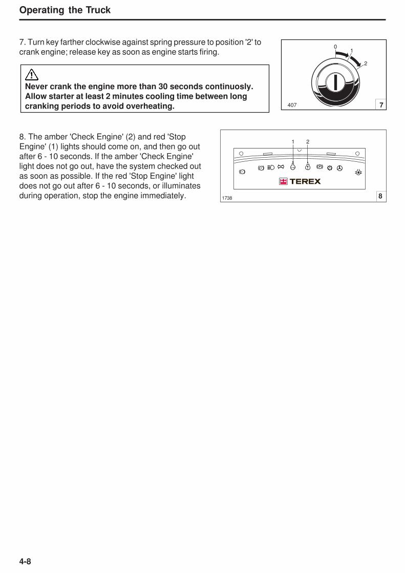
4-8
Operating the Truck
1738
7. Turn key farther clockwise against spring pressure to position '2' to
crank engine; release key as soon as engine starts firing.
Never crank the engine more than 30 seconds continuosly.
Allow starter at least 2 minutes cooling time between long
cranking periods to avoid overheating.
8. The amber 'Check Engine' (2) and red 'Stop
Engine' (1) lights should come on, and then go out
after 6 - 10 seconds. If the amber 'Check Engine'
light does not go out, have the system checked out
as soon as possible. If the red 'Stop Engine' light
does not go out after 6 - 10 seconds, or illuminates
during operation, stop the engine immediately.
407
01
2
7
PSTOP
1
2
1 2
8
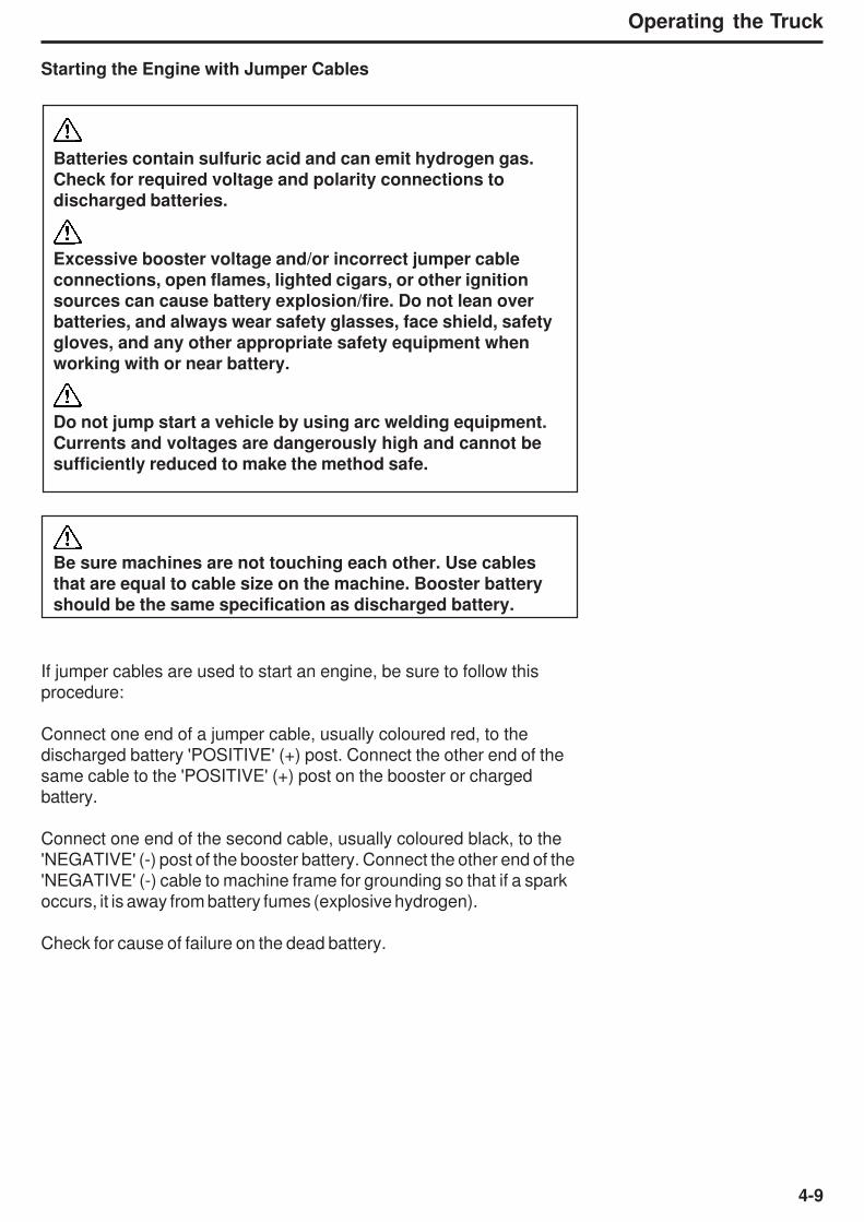
4-9
Operating the Truck
Starting the Engine with Jumper Cables
Batteries contain sulfuric acid and can emit hydrogen gas.
Check for required voltage and polarity connections to
discharged batteries.
Excessive booster voltage and/or incorrect jumper cable
connections, open flames, lighted cigars, or other ignition
sources can cause battery explosion/fire. Do not lean over
batteries, and always wear safety glasses, face shield, safety
gloves, and any other appropriate safety equipment when
working with or near battery.
Do not jump start a vehicle by using arc welding equipment.
Currents and voltages are dangerously high and cannot be
sufficiently reduced to make the method safe.
Be sure machines are not touching each other. Use cablesthat are equal to cable size on the machine. Booster batteryshould be the same specification as discharged battery.
If jumper cables are used to start an engine, be sure to follow this
procedure:
Connect one end of a jumper cable, usually coloured red, to the
discharged battery 'POSITIVE' (+) post. Connect the other end of the
same cable to the 'POSITIVE' (+) post on the booster or charged
battery.
Connect one end of the second cable, usually coloured black, to the
'NEGATIVE' (-) post of the booster battery. Connect the other end of the
'NEGATIVE' (-) cable to machine frame for grounding so that if a spark
occurs, it is away from battery fumes (explosive hydrogen).
Check for cause of failure on the dead battery.

4-10
Operating the Truck
1755 1
1750 1b
COLD
ADD
COLD
FULL
HOT
FULL
HOT
ADD
2160
Pre-Operating Checks
Make sure all cab glass, mirrors and lights are clean. Test all controls
to ensure they are functioning properly. Move transmission gear shift
control momentarily to 'REVERSE' to make sure the reverse alarm
sounds.
1. Transmission - Hot Oil Level - The parking brake must be applied
and the machines wheels securely blocked while carrying out this
check. With the engine idling, transmission in 'NEUTRAL' and at
normal operating temperature 80° C (176° F), the oil level should be
up to, but not over, the upper mark on the dipstick. Add oil if low.
2. Mirrors and CCTV- Ensure mirrors and CCTV are positioned
correctly to maximise visibility. (Refer to section “Safety” for adjustment)

4-11
Operating the Truck
Brake Function Checks
In addition to the above Pre-operating checks, the following brake
function checks must be carried out to determine if both the service and
emergency brake systems are functional before operating the machine.
Make sure the area around the machine is clear of personnel
and obstructions before carrying out these checks.
Note: The following checks are NOT intended to measure maximum
brake holding ability.
Service Brake Holding Ability Check
Depress service brake pedal and move transmission gear shift to
Drive. Pull the parking-emergency brake control out to release the
brakes. Depress accelerator control and accelerate engine to 1 350
rev/min. The machine should not move. Decelerate engine, shift
transmission to 'NEUTRAL' so that the parking brake is applied
automatically, before releasing the service brake pedal.
Emergency Brake Holding Ability Check
Push parking-emergency brake control in to apply 'EMERGENCY'
brakes and move transmission gear shift to Drive. Depress accelerator
control and accelerate engine to 1 350 rev/min. The machine should not
move. Decelerate engine, move gear shift control to 'NEUTRAL' so
that the parking brake is applied automatically, before releasing the
service brake pedal.
Note: Brake holding effort required to hold a machine static at a
specific rev/min, can vary from machine to machine due to differences
in engine performance, powertrain efficiencies, etc., as well as
differences in brake holding ability.
Note: As an indication of system deterioration, the engine rev/min at
which point the machine moved, with the service or emergency
brakes applied, can be compared against the engine rev/min your
specific machine was able to hold to on a previous check.
If the machine moves during the above checks, stop the
machine, apply the parking brake and do not operate until thefault is corrected.
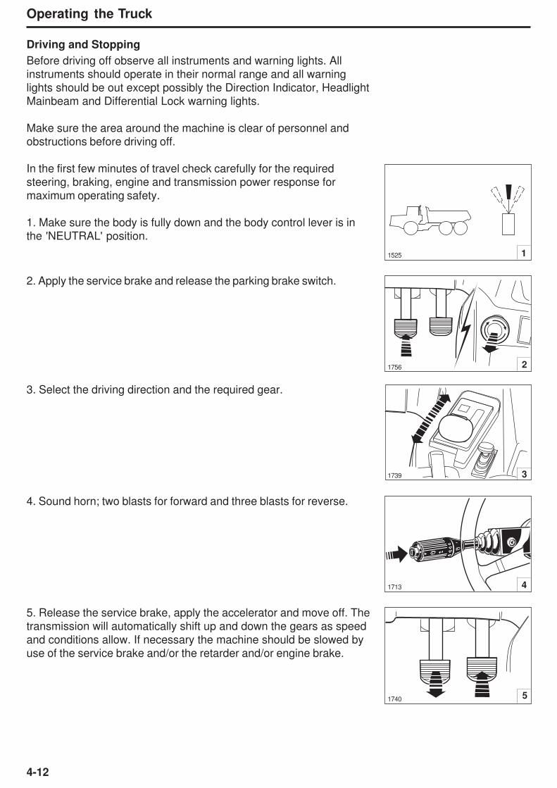
4-12
Operating the Truck
1525 1
1756 2
1739 3
Driving and Stopping
Before driving off observe all instruments and warning lights. All
instruments should operate in their normal range and all warning
lights should be out except possibly the Direction Indicator, Headlight
Mainbeam and Differential Lock warning lights.
Make sure the area around the machine is clear of personnel and
obstructions before driving off.
In the first few minutes of travel check carefully for the required
steering, braking, engine and transmission power response for
maximum operating safety.
1. Make sure the body is fully down and the body control lever is in
the 'NEUTRAL' position.
2. Apply the service brake and release the parking brake switch.
3. Select the driving direction and the required gear.
4. Sound horn; two blasts for forward and three blasts for reverse.
5. Release the service brake, apply the accelerator and move off. The
transmission will automatically shift up and down the gears as speed
and conditions allow. If necessary the machine should be slowed by
use of the service brake and/or the retarder and/or engine brake.
41713
1740 5
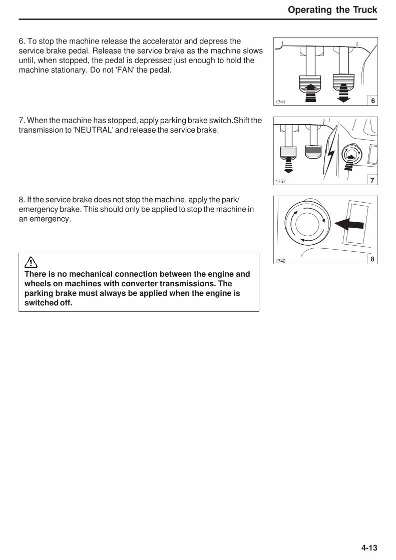
4-13
Operating the Truck
6. To stop the machine release the accelerator and depress the
service brake pedal. Release the service brake as the machine slows
until, when stopped, the pedal is depressed just enough to hold the
machine stationary. Do not 'FAN' the pedal.
7. When the machine has stopped, apply parking brake switch.Shift the
transmission to 'NEUTRAL' and release the service brake.
8. If the service brake does not stop the machine, apply the park/
emergency brake. This should only be applied to stop the machine in
an emergency.
1741 6
1757 7
1742 8
There is no mechanical connection between the engine andwheels on machines with converter transmissions. Theparking brake must always be applied when the engine isswitched off.
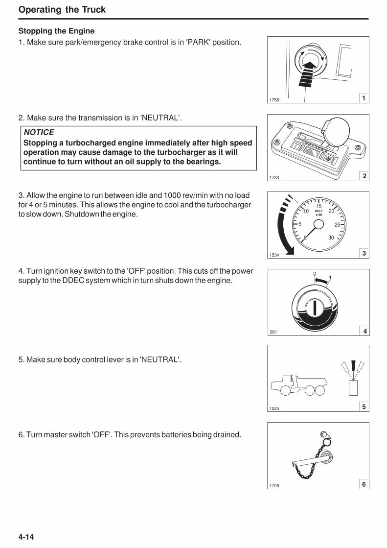
4-14
Operating the Truck
Stopping the Engine
1. Make sure park/emergency brake control is in 'PARK' position.
2. Make sure the transmission is in 'NEUTRAL'.
3. Allow the engine to run between idle and 1000 rev/min with no load
for 4 or 5 minutes. This allows the engine to cool and the turbocharger
to slow down. Shutdown the engine.
4. Turn ignition key switch to the 'OFF' position. This cuts off the power
supply to the DDEC system which in turn shuts down the engine.
5. Make sure body control lever is in 'NEUTRAL'.
6. Turn master switch 'OFF'. This prevents batteries being drained.
11758
MO
DE
SELECT
MONIT
OR
1 2 3 4 5 D N R
21733
0
5
1015
20
25
min-1
x100
30
31534
51525
61709
281 4
01
NOTICE
Stopping a turbocharged engine immediately after high speed
operation may cause damage to the turbocharger as it will
continue to turn without an oil supply to the bearings.
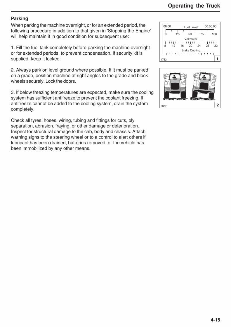
4-15
Operating the Truck
Parking
When parking the machine overnight, or for an extended period, the
following procedure in addition to that given in 'Stopping the Engine'
will help maintain it in good condition for subsequent use:
1. Fill the fuel tank completely before parking the machine overnight
or for extended periods, to prevent condensation. If security kit is
supplied, keep it locked.
2. Always park on level ground where possible. If it must be parked
on a grade, position machine at right angles to the grade and block
wheels securely. Lock the doors.
3. If below freezing temperatures are expected, make sure the cooling
system has sufficient antifreeze to prevent the coolant freezing. If
antifreeze cannot be added to the cooling system, drain the system
completely.
Check all tyres, hoses, wiring, tubing and fittings for cuts, ply
separation, abrasion, fraying, or other damage or deterioration.
Inspect for structural damage to the cab, body and chassis. Attach
warning signs to the steering wheel or to a control to alert others if
lubricant has been drained, batteries removed, or the vehicle has
been immobilized by any other means.
Fuel Level
Voltmeter
00.00 00.00.00
0
8 12 16 20 24 28 32
25 50 75 100
Brake Cooling
1752 1
2037 2

4-16
Operating the Truck
This Page Intentionally Left Blank
5-1
Working the Truck
5 - Working the Truck

5-2
Working the Truck
This Page Intentionally Left Blank
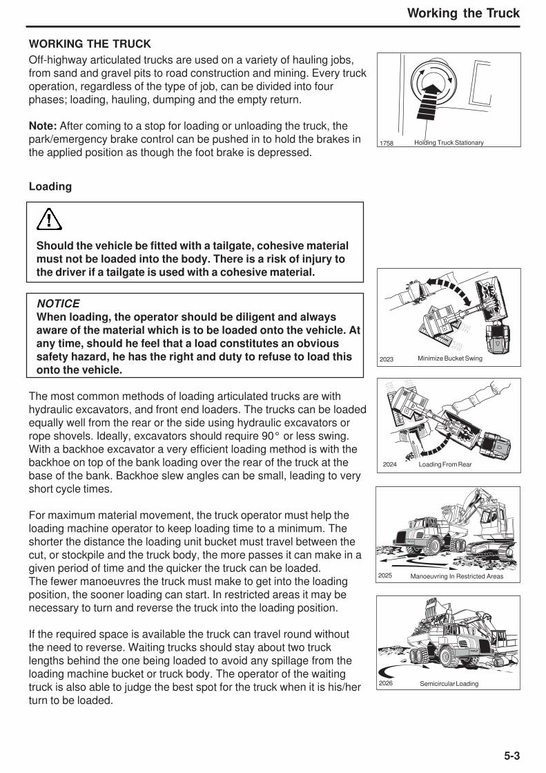
5-3
Working the Truck
WORKING THE TRUCK
Off-highway articulated trucks are used on a variety of hauling jobs,
from sand and gravel pits to road construction and mining. Every truck
operation, regardless of the type of job, can be divided into four
phases; loading, hauling, dumping and the empty return.
Note: After coming to a stop for loading or unloading the truck, the
park/emergency brake control can be pushed in to hold the brakes in
the applied position as though the foot brake is depressed.
Loading
Should the vehicle be fitted with a tailgate, cohesive material
must not be loaded into the body. There is a risk of injury to
the driver if a tailgate is used with a cohesive material.
NOTICE
When loading, the operator should be diligent and always
aware of the material which is to be loaded onto the vehicle. At
any time, should he feel that a load constitutes an obvious
safety hazard, he has the right and duty to refuse to load this
onto the vehicle.
The most common methods of loading articulated trucks are with
hydraulic excavators, and front end loaders. The trucks can be loaded
equally well from the rear or the side using hydraulic excavators or
rope shovels. Ideally, excavators should require 90° or less swing.
With a backhoe excavator a very efficient loading method is with the
backhoe on top of the bank loading over the rear of the truck at the
base of the bank. Backhoe slew angles can be small, leading to very
short cycle times.
For maximum material movement, the truck operator must help the
loading machine operator to keep loading time to a minimum. The
shorter the distance the loading unit bucket must travel between the
cut, or stockpile and the truck body, the more passes it can make in a
given period of time and the quicker the truck can be loaded.
The fewer manoeuvres the truck must make to get into the loading
position, the sooner loading can start. In restricted areas it may be
necessary to turn and reverse the truck into the loading position.
If the required space is available the truck can travel round without
the need to reverse. Waiting trucks should stay about two truck
lengths behind the one being loaded to avoid any spillage from the
loading machine bucket or truck body. The operator of the waiting
truck is also able to judge the best spot for the truck when it is his/her
turn to be loaded.
Holding Truck Stationary1758
2023 Minimize Bucket Swing
2024 Loading From Rear
2025 Manoeuvring In Restricted Areas
2026 Semicircular Loading

5-4
Working the Truck
On some jobs, the loading machine might work most efficiently whentrucks are positioned on both sides of the loader. Thus, while one
truck is being loaded, another can move into position on the opposite
side of the loader and the loading machine can swing over to load the
next truck with a minimum of lost time. Since the truck is usually
backed into the loading position with this method, the operator must
be alert and careful while backing.
For fastest, most accurate loading, when being loaded by a front endloader, the truck operator should stop the truck on the most level area
and at an angle to the face of the bank or stockpile. This minimizes
loader travel time, particularly with a raised, full bucket. Where
possible, the truck should also locate downwind of the loader when
dusty material is being loaded on a windy day. This practice improves
both working conditions and visibility for the loader operator.
A cleanup dozer or small loader is often worked in conjunction with
the main loading machine to keep the area clear of bucket spillage formaximum efficiency of the loading operation. The truck operator must
always be alert to the position of the cleanup machine when entering
the loading area to avoid congestion, and, for maximum safety.
Avoid rocks and other shovel spillage that can needlessly
damage tyres or other truck components. Allow the cleanup
machine sufficient time to clear up such debris.
Do not move the truck into loading position with the shovel
bucket swinging overhead. Large rocks that might fall from
the bucket can be dangerous to both the operator and the
truck.
Keep your head and arms inside the cab during loading to
avoid the danger of falling rocks or other shovel spillage.
When the loader operator signals that the truck is loaded, sound two
blasts on the horn for forward movement and three blasts for reverse
movement. Select the correct gear and release the brakes. Move out of
the loading area and onto the haul road, with the least possible delay, to
allow any waiting truck to move into the loading position as soon as
possible.
2027 Loading Both Sides
Loading With Front End Loader2028
Watch Cleanup Machine2029
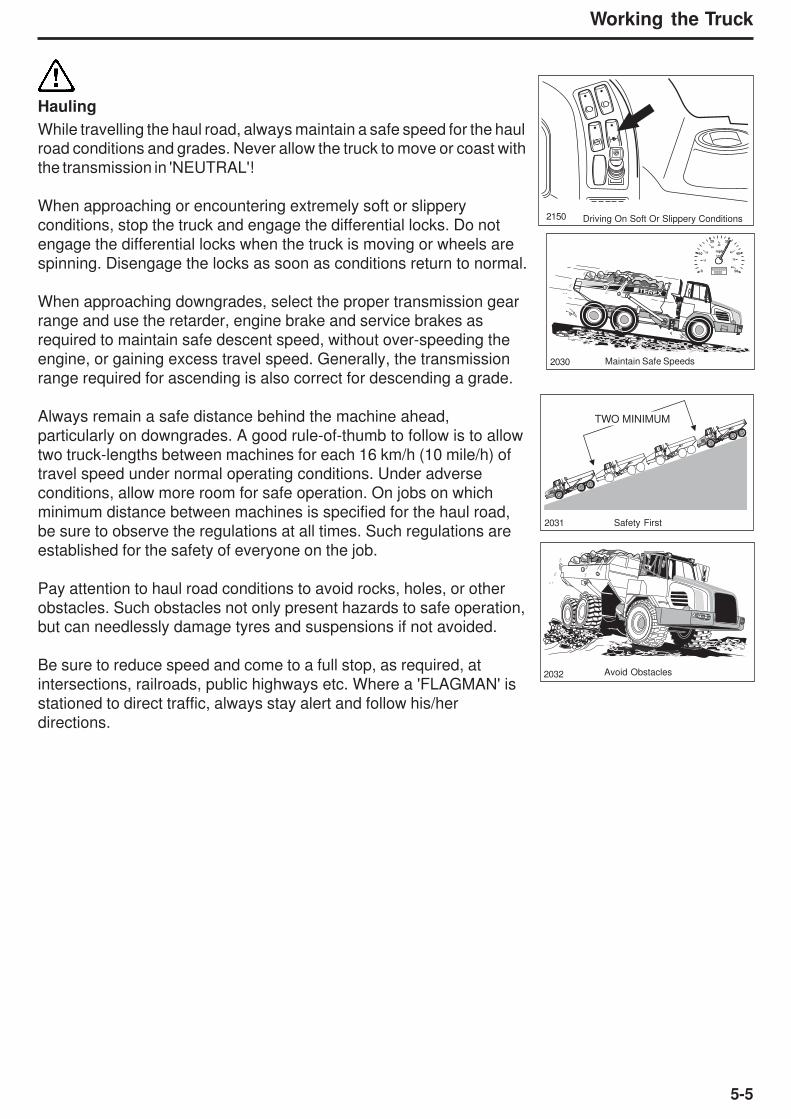
5-5
Working the Truck
Hauling
While travelling the haul road, always maintain a safe speed for the haulroad conditions and grades. Never allow the truck to move or coast with
the transmission in 'NEUTRAL'!
When approaching or encountering extremely soft or slippery
conditions, stop the truck and engage the differential locks. Do not
engage the differential locks when the truck is moving or wheels are
spinning. Disengage the locks as soon as conditions return to normal.
When approaching downgrades, select the proper transmission gearrange and use the retarder, engine brake and service brakes as
required to maintain safe descent speed, without over-speeding the
engine, or gaining excess travel speed. Generally, the transmission
range required for ascending is also correct for descending a grade.
Always remain a safe distance behind the machine ahead,
particularly on downgrades. A good rule-of-thumb to follow is to allow
two truck-lengths between machines for each 16 km/h (10 mile/h) oftravel speed under normal operating conditions. Under adverse
conditions, allow more room for safe operation. On jobs on which
minimum distance between machines is specified for the haul road,
be sure to observe the regulations at all times. Such regulations are
established for the safety of everyone on the job.
Pay attention to haul road conditions to avoid rocks, holes, or other
obstacles. Such obstacles not only present hazards to safe operation,but can needlessly damage tyres and suspensions if not avoided.
Be sure to reduce speed and come to a full stop, as required, at
intersections, railroads, public highways etc. Where a 'FLAGMAN' is
stationed to direct traffic, always stay alert and follow his/her
directions.
Maintain Safe Speeds2030
2031 Safety First
2032 Avoid Obstacles
2150 Driving On Soft Or Slippery Conditions
10
10
20
3040
50
60
70
80
km/h
20 30
40mph
500 0000000
0000
TWO MINIMUM

5-6
Working the Truck
Dumping
When dumping the operator should steer the vehicle ensuring that it
is straight and with the loaded body on level ground. The dumping
operation usually depends upon the type of material being hauled.
For instance, overburden and other waste material is usually dumpedover a spoil bank or piled into large mounds. The dumping on a job of
this type might be controlled by a dump 'SPOTTER', 'FLAGMAN' or
'BANKSMAN' or second person who directs the truck to its dumping
area. While backing to dump, the operator must watch the
'SPOTTER' at all times and follow his/her direction. Under no
circumstances should the operator leave the seat to gain better
visibility while backing. Always remain seated to maintain maximum
machine control.
Mineral ores, blasted rock etc., are usually dumped into a hopper, or
crusher, where it is processed. When dumping into a hopper, the
operator, in order to avoid excess wear on the tyres, must avoid
hitting the protecting rail at the hopper. If a DRIVEOVER HOPPER is
used, the operator must avoid rubbing the tyre inner sidewalls.
When hauling dirt or rock from a borrow pit into a fill area such as an
earth-fill dam, the load is usually dumped in a string with other loadsand the loads smoothed out with a crawler tractor. When dumping on
a fill of this type, the operator usually works alone and picks his/her
own dumping place. To save bulldozer work and cleaning up, the
load should be dumped as close as possible to the preceding load.
The operator should pull past the preceding load, turn in line with the
string and back the truck until it is within a few feet of the last load.
This assures that the load will fall in the right place. No matter what
kind of job the operator is working, there are a few things which arecommon to all jobs and which the operator should observe.
Push the body control lever back into the 'RAISE' position and
accelerate the engine. Decelerate the engine to slow the raising speed
2033 Manoeuvring To Dump
2034 Keep A Safe Distance From The Edge
2035 Keep Wheels LevelNOTICE
Before raising the body, make sure that the rear wheels are on
firm level ground. If one wheel is higher than the other, a
twisting strain is imposed upon the body hinge pins, hoists
and chassis. Stop the truck, allow the engine to slow to idle,
shift the transmission to 'NEUTRAL' so that the parking brake
is applied automatically and the vehicle is held stationary.
When dumping over a spoil bank without a 'SPOTTER',
know how close the truck can safely approach the edge
under all weather conditions. If in doubt as to dumpingsafety, dump the load a safe distance from the edge so that
it can be pushed over the edge later.

5-7
Working the Truck
as the hoists approach their maximum extension. When the body hasbeen raised to the desired height, release the control lever into the
‘NEUTRAL’ (Hold) position until the body is to be lowered. Do not
hold the lever in the 'RAISE' position when the hoists are fully
extended to prevent unnecessary hydraulic system relief valve
operation.
NOTICE
Never 'JUMP DUMP' the truck by bouncing the rear tyres
against a stop block, or otherwise jarring the body in its raised
position, to dislodge stuck or frozen material. The tremendous
loads that this practice develops on the body pin area, chassis
and hydraulic system can cause needless, extensive stresses.
Once the load has been dumped, push the control lever fully forwardinto the detent 'POWER DOWN' position and accelerate the engine. As
the hoists approach their fully retracted positions, decelerate the
engine. At a predetermined body height a proximity sensor causes the
body control lever to spring back to 'NEUTRAL' position, allowing the
body to float onto the chassis under it's own weight.
Empty Return
Make sure the body is completely lowered, the body control lever is inthe 'NEUTRAL' position and transmission is in correct gear range
before releasing the brakes and moving away from the dump site.
Do NOT drive the truck with the body up. No articulated truckis stable in this condition and, apart from the risk of a rear-end
topple, there can be severe danger from contacting overhead
electric cables, trees, or bridges over the haul route.
Except for the above, the procedure for returning empty to the loading
area is the same as that given earlier for 'HAULING'.
1525 Keep Control Lever in 'NEUTRAL'
2036 Don't Jump Dump
2229 Make sure Body is Fully Down

5-8
Working the Truck
This Page Intentionally Left Blank

6-1
Roading
6 - Roading

6-2
Roading
This Page Intentionally Left Blank
6-3
Roading
ROADING
These machines are equipped with cylinders containingcompressed nitrogen gas. Transportation of these machinesby any method may require a special permit from theappropriate authority of the country involved. Consult yourDealer for details.
General'ROADING' (operating a truck over public highways) requires specialcare and attention. Trucks, because of their large size, are slower andless manoeuvrable than most other machines encountered on the road.Yet, while on the road, they must be operated for extended periods oftime at, or near, maximum speeds.
Before 'ROADING' a truck for an extended distance between jobs, orbetween widely scattered sections of a job, the machine must beproperly equipped and in good condition. It is also recommended tocarry a 'Warning Triangle'.
The operator must use extra care while on the public highways andremain constantly alert, especially for overhead cables and lowbridges.
Necessary permits must be obtained from the proper authorities beforethe machine is 'ROADED' on public highways.
Preparation Prior to RoadingLubricationThoroughly lubricate and service all components and systems asdescribed under 'LUBRICATION AND SERVICING' in this handbookand/or maintenance manuals for this machine.
InspectionPerform all pre-starting and post-starting checks described in thisHandbook. Pay particular attention to the function of all instruments andlights, and make any repairs necessary.
NOTICE
Improper tyre inflation during over-the-road operation cancause rapid tyre deterioration by overheating. Tyre pressuresincrease with heat. Always check pressures while tyre is cold.Consult your tyre dealer for proper pressures and tyre speedlimits for roading.
Check the inflation pressures of all tyres, while cold, with an accuratetyre pressure gauge. Inflate tyres if necessary, while cold, to therecommended pressure for 'ROADING'. Inspect all tyres thoroughlyand carefully for stones or other debris embedded in the treads orcarcasses. Inspect for cuts, bruises, burned beads abnormal wear
NOTICE
Make sure the body islowered and bodycontrol lever is in the'NEUTRAL' position.Failure to comply to thiscould result inoverheating the hydraulicoil and failure of thehydraulic systemcomponents.
Make sure the differentiallock switch remains inthe 'OFF' position whenroading. Failure tocomply to this couldresult in damage to thetransmission and axlecomponents.
6-4
Roading
and damaged wheels rims. Replace any damaged or excessivelyworn tyres.
Check all hoses, drain cocks, fuel level check cocks, and otherpotential sources of leaks. Make sure that all leaks are repaired andthat all drain cocks are sufficiently tightened to avoid subsequentloosening. Make sure that all warning flags, oversize load signs etc.are in place and secure.
Clean all glass and adjust the seat for proper operation of all controls.
Check the lights, horn, windscreen wipers, heater, defroster, headlightdip control, and all controls for proper operation.
Make sure the truck body is empty, fully lowered and the body controllever is in the 'NEUTRAL' position.
Make sure the differential lock switch is in the 'OFF' position.
Drive transmission through all gears while slowly accelerating engine.
In Case of Trouble
If trouble develops on route, move machine off the road at the first safeparking place, and shut off the engine. Carefully note as many of thesymptoms of the trouble as possible, such as rough engine operationwith loss of power and overheating, or loss of speed and transmissionclutch pressure with normal engine operation etc.
If the area in which the trouble occurs requires that the machine be leftunattended while the trouble is reported by phone, disconnect abattery cable and apply security locks, if so equipped, before leavingthe parked machine. Make sure body is completely lowered and theparking brake is applied.
Report the following data as soon as possible:
1. Exact location.
2. Destination.
3. Truck Serial Number
4. The nature of the trouble (with as many details as possible) and the time and conditions under which it happened.
5. The telephone number at which the machine operator can be reached.
NOTICE
Do not attempt to restart or operate the machine unlessinstructed to do so. An engine, pump, transmission or othercomponent that develops a minor defect can be completelydestroyed in just a few extra minutes of unnecessaryoperation.
7-1
Moving a Disabled Truck
7 - Moving a Disabled Truck

7-2
Moving a Disabled Truck
This Page Intentionally Left Blank
7-3
Moving a Disabled Truck
MOVING DISABLED TRUCKAny unusual power train noises noted while operating the truck shouldbe reported to those responsible for maintenance. Should the powertrain, hydraulic or electrical systems fail, the vehicle should be stoppedand shut down immediately until suitable repairs can be made. If thefailure is in the power train and the truck must be moved to a servicearea or workshop to make required repairs, it is advisable to carry outthe following procedures to prevent any possible additional damage,which may be caused by the wheels turning the power train as thevehicle is driven or towed.
If the transmission or drop box is at fault, disconnect the drivelines tothe axles and dropbox before moving the vehicle.
If a differential or planetary is at fault, carry out the followingprocedure for the component concerned: Disconnect drivelines,remove planetary covers and remove the axle shafts. Remove thepinion gears from their covers. Replace the planetary pins in thecovers, and refit the planetary covers on the drive wheels to retainlubricant and prevent ingress of dirt.
If possible, start the engine to provide the required hydraulic pressurefor steering and braking. If the nature of the trouble prevents engineoperation, repairs must be made on the site of the breakdown, orspecial arrangements made for towing the vehicle safely to the repairarea without braking and steering power.
Never allow riders on a vehicle being towed without sufficienthydraulic pressure for safe braking.
If the parking brake must be released, but the engine cannot beoperated to provide the required hydraulic pressure or if there iselecrical failure, the brake can be released manually by following thisprocedure:
Block all wheels securely. Turn the hex-head on the parking brakeactuator anticlockwise until the brake pads are free from the disc.When the hydraulic system is repaired, return the actuator to itsoriginal position by turning the hex-head fully clockwise.
Connect a suitable towing bar to one of the lugs on the tractor frameof the disabled vehicle and reverse another vehicle, in a straight andin-line manoeuvre, towards the disabled vehicle. Connect theopposite end of the towing bar to the towing pin of the recoveryvehicle and ensure that it is securely locked.
Note: An alternative method of towing a disabled vehicle is byconnecting an A-Frame arrangement to the lugs on the tractorframe of the disabled vehicle and the towing pin of therecovery vehicle.
Removing the driveline
between the parkingbrake and the rear axlesor removing the axleshafts and planetarycovers or pinion gearsfrom the axles will makethe parking brakeineffective.
Uncontrolled vehiclemovement hazard.There is no mechanicalconnection between thevehicle wheels and theengine when theparking brake isreleased. Beforereleasing the parkingbrake, make sure thevehicle wheels aresecured with chockblocks to prevent orrestrict unexpectedvehicle movement.
When moving thevehicle with insufficienthydraulic pressure, forsafe braking andsteering, use extremecaution to ensurepersonnel and propertysafety.
Make sure the parkingbrake actuator isreturned to its originalposition, and theparking brake isoperating correctly,before removing thechock blocks from thewheels.

7-4
Moving a Disabled Truck
This Page Intentionally Left Blank
8-1
Lubrication and Servicing
8 - Lubrication and Servicing

8-2
Lubrication and Servicing
This Page Intentionally Left Blank

8-3
Lubrication and Servicing
SAFETYDo not allow unauthorized personnel to service or maintain thismachine. Study the Operator’s Handbook and Maintenance Manualbefore starting, operating or servicing this machine. Always followprocedures and safety precautions detailed in the MaintenanceManual.
Always attach a 'DO NOT OPERATE' or similar warning sign toignition switch or a control and lockout before cleaning, lubricating orservicing the machine.
Never allow anyone to work on the machine while it is moving. Makesure no one is on the machine before working on it.
Do not work under or near unblocked or unsupported body. Alwaysuse the body safety prop. Body prop must only be used when the bodyis empty.
Do not work under or near any unblocked or unsupported linkage, partor machine.
Always shut down machine according to the procedure under'Stopping The Engine', described on Page 4-14. Turn off the masterswitch before cleaning, lubricating or servicing the machine except ascalled for in this Handbook or Maintenance Manual.
Always install steering lock bar before adjusting or servicing themachine with the engine running. Refer to 'General' safety section onPage 2-4.
Always relieve pressure before servicing any pressurized system.Follow the procedures and safety precautions detailed in the relevantMaintenance Manual section.
Escaping fluids under pressure can penetrate skin.
When changing oil in the engine, transmission and hydraulic systems,or removing hydraulic lines, remember that the oil may be hot and cancause burns to unprotected skin.
When working on or around exhaust components, remember that thecomponents may be hot and can cause burns to unprotected skin.
Always deflate tyre before attempting to remove any embedded objectsor removing the tyre and rim assembly from the machine.
Always use a self-attaching chuck with a long airline and stand to oneside while the tyre is inflating. Refer to Section 160-0050, Wheel Rimand Tyre in the Maintenance Manual.
EXPLOSION HAZARD
When working around battery area, keep all flames and sparks away from batteries.
SAFETY
MANUAL
1767
DO NOT
OPERATE
1775
1781
15333273
Injection Hazard.Escaping fluid under pressurecan penetrate skin, causingserious injury.
Relieve pressure beforedisconnecting hydraulic lines.Keep away from leaks and pinholes. Use a piece of cardboard or paper to searchfor leaks. Do not use hand.
Fluid injected into the skin must besurgically removed within a fewhours by a doctor familiar with this type of injury or gangrenewill result.
WARNING

8-4
Lubrication and Servicing
LUBRICATION AND SERVICINGLubrication is an essential part of preventive maintenance. It isimportant that the instructions regarding types of lubricants and thefrequency of their application be followed to prolong the useful life ofthe machine. Periodic lubrication of moving parts reduces to aminimum the possibility of mechanical failures.
Thoroughly clean all fittings, caps and plugs to prevent contaminantsfrom entering the system while servicing.
Lubricants must be at operating temperature when draining.
Do not operate any system unless oil level is within the operatingrange as indicated on oil level dip stick, sight gauge or level plug.
Small circles on the following illustrations represent points at whichlubrication or servicing must take place, at the intervals indicated onthe left-hand side of the lubrication chart.
The number on the illustrations contain reference numbers whichcorrespond to the 'Ref. Points' column of the chart.
All change and service periods are recommendations based onaverage operating conditions. Lubricants showing evidence ofexcessive heat, oxidation or dirt should be changed more frequentlyto prevent these conditions. Lubricant change and service periodsmust be established on the basis of individual job conditions.

8-5
Lubrication and Servicing
LUBRICATION AND SERVICE CHARTInterval Ref. No. of ServiceHours Points Identification Service Instructions Points Lubricant Quantities
1 Engine Check oil level. Add oil if low. 1 EO As required.10 2 Transmission Check oil level. Add oil if low 1 TranSynd / As required.
(Daily) TES 295*3 Hydraulic Tank Check oil level. Add if low. 2 HO / Textran HD10 As required.4 Radiator Expansion Tank Check coolant level. Add if low 1 Ethylene Glycol As required.5 Primary Fuel Filter / Check. Drain as required. 1 - -
Water Separator1 Drive Belt Check for damage. 1 See engine Manual27 Fuel Tank Check fuel level. Add if low. 1 - As required.1 Engine Crankcase Breather Inspect and clean if required. - -24 Cooling Fans Check for damage.6 Hydraulic Filter Restriction Check. Replace element if required. 1
IndicatorTyres Check condition and pressure. 6
14 Dropbox Check oil level. Add oil if low 1 EO As required.General Walk round vehicle, check for debris, - Refer to chart.
leaks and damage.1 Engine Air Cleaner Check. Renew element if required 1 - See Note 7
50 7 Battery Electrolyte Check level. Add electrolyte if low. 2 - As required.(Weekly) 8 Wheel rim nuts Check Torque. 114 - 600 Nm (442 Ibf ft)
9 Cab Ventilation Filter Inspect and clean if required. 110 Panhard Rod Bearings Lubricate 4 EP, NLGI See Note 1.19 Oscillation Bush Lubricate 2 EP, NLGI See Note 1.20 Suspension Beam Bushings Lubricate 2 EP, NLGI See Note 1.23 Body Hinge/Optional Tailgate Pins Lubricate 2 EP, NLGI See Note 1.21 Steering Cylinder Pins Lubricate 4 EP, NLGI See Note 1.22 Body Cylinder Pins Lubricate 4 EP, NLGI See Note 1.16 Differential Breathers Clean if required. 3
18 Articulation Bearings Lubricate 2 EP LI COMP See Notes 1 and 2.250 25 Parking Brake Pads Check wear. Renew if required. 2
(Monthly) 2 Transmission Breather Clean if required. 124 Radiator and Coolers Clean and inspect fins. See Note 6.26 OCDB Plate Check wear. Replace if required.15 Secondary Fuel Filter Renew 117 Wheel planetaries Check oil level. Add oil if low 6 EPL As required.16 Differentials Check oil level. Add oil if low 3 EPL & LZ See Note 4.5 PrimaryFuel Filter/Water Renew 1
Separator19 Oscillation Pivot Check end float. Adjust if required. 21 Drive Belt Check tension. Tighten if required 1
2153Lubrication and Servicing Points
24 35 28 27 13 11 12 21 16 18 22 19 25 22 16 20 1016 23
2320222622211215 27 345 3233311 3414 1017 8
9
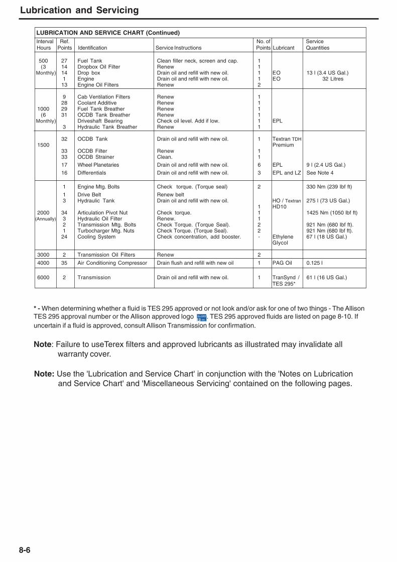
8-6
Lubrication and Servicing
Note: Use the 'Lubrication and Service Chart' in conjunction with the 'Notes on Lubricationand Service Chart' and 'Miscellaneous Servicing' contained on the following pages.
LUBRICATION AND SERVICE CHART (Continued)Interval Ref. No. of ServiceHours Points Identification Service Instructions Points Lubricant Quantities
500 27 Fuel Tank Clean filler neck, screen and cap. 1(3 14 Dropbox Oil Filter Renew 1
Monthly) 14 Drop box Drain oil and refill with new oil. 1 EO 13 l (3.4 US Gal.)1 Engine Drain oil and refill with new oil. 1 EO 32 Litres
13 Engine Oil Filters Renew 2
9 Cab Ventilation Filters Renew 128 Coolant Additive Renew 1
1000 29 Fuel Tank Breather Renew 1(6 31 OCDB Tank Breather Renew 1
Monthly) Driveshaft Bearing Check oil level. Add if low. 1 EPL3 Hydraulic Tank Breather Renew 1
32 OCDB Tank Drain oil and refill with new oil. 1 Textran TDH1500 Premium
33 OCDB Filter Renew 133 OCDB Strainer Clean. 1
17 Wheel Planetaries Drain oil and refill with new oil. 6 EPL 9 l (2.4 US Gal.)
16 Differentials Drain oil and refill with new oil. 3 EPL and LZ See Note 4
1 Engine Mtg. Bolts Check torque. (Torque seal) 2 330 Nm (239 Ibf ft)
1 Drive Belt Renew belt3 Hydraulic Tank Drain oil and refill with new oil. HO / Textran 275 l (73 US Gal.)
1 HD102000 34 Articulation Pivot Nut Check torque. 1 1425 Nm (1050 lbf ft)
(Annually) 3 Hydraulic Oil Filter Renew. 12 Transmission Mtg. Bolts Check Torque. (Torque Seal). 2 921 Nm (680 Ibf ft).1 Turbocharger Mtg. Nuts Check Torque. (Torque Seal). 2 921 Nm (680 Ibf ft).
24 Cooling System Check concentration, add booster. - Ethylene 67 l (18 US Gal.)Glycol
3000 2 Transmission Oil Filters Renew 2
4000 35 Air Conditioning Compressor Drain flush and refill with new oil 1 PAG Oil 0.125 l
6000 2 Transmission Drain oil and refill with new oil. 1 TranSynd / 61 l (16 US Gal.)TES 295*
* - When determining whether a fluid is TES 295 approved or not look and/or ask for one of two things - The AllisonTES 295 approval number or the Allison approved logo . TES 295 approved fluids are listed on page 8-10. Ifuncertain if a fluid is approved, consult Allison Transmission for confirmation.
Note: Failure to useTerex filters and approved lubricants as illustrated may invalidate allwarranty cover.
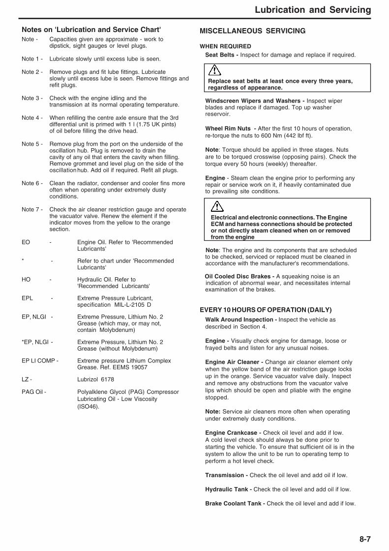
8-7
Lubrication and Servicing
Notes on 'Lubrication and Service Chart'Note - Capacities given are approximate - work to
dipstick, sight gauges or level plugs.
Note 1 - Lubricate slowly until excess lube is seen.
Note 2 - Remove plugs and fit lube fittings. Lubricateslowly until excess lube is seen. Remove fittings andrefit plugs.
Note 3 - Check with the engine idling and thetransmission at its normal operating temperature.
Note 4 - When refilling the centre axle ensure that the 3rddifferential unit is primed with 1 l (1.75 UK pints)of oil before filling the drive head.
Note 5 - Remove plug from the port on the underside of theoscillation hub. Plug is removed to drain thecavity of any oil that enters the cavity when filling.Remove grommet and level plug on the side of theoscillation hub. Add oil if required. Refit all plugs.
Note 6 - Clean the radiator, condenser and cooler fins moreoften when operating under extremely dustyconditions.
Note 7 - Check the air cleaner restriction gauge and operatethe vacuator valve. Renew the element if theindicator moves from the yellow to the orangesection.
EO - Engine Oil. Refer to 'RecommendedLubricants'
* - Refer to chart under 'RecommendedLubricants'
HO - Hydraulic Oil. Refer to'Recommended Lubricants'
EPL - Extreme Pressure Lubricant,specification MIL-L-2105 D
EP, NLGI - Extreme Pressure, Lithium No. 2Grease (which may, or may not,contain Molybdenum)
*EP, NLGI - Extreme Pressure, Lithium No. 2Grease (without Molybdenum)
EP LI COMP - Extreme pressure Lithium ComplexGrease. Ref. EEMS 19057
LZ - Lubrizol 6178
PAG Oil - Polyalklene Glycol (PAG) CompressorLubricating Oil - Low Viscosity(ISO46).
MISCELLANEOUS SERVICING
WHEN REQUIREDSeat Belts - Inspect for damage and replace if required.
Replace seat belts at least once every three years,regardless of appearance.
Windscreen Wipers and Washers - Inspect wiperblades and replace if damaged. Top up washerreservoir.
Wheel Rim Nuts - After the first 10 hours of operation,re-torque the nuts to 600 Nm (442 lbf ft).
Note: Torque should be applied in three stages. Nutsare to be torqued crosswise (opposing pairs). Check thetorque every 50 hours (weekly) thereafter.
Engine - Steam clean the engine prior to performing anyrepair or service work on it, if heavily contaminated dueto prevailing site conditions.
Electrical and electronic connections. The EngineECM and harness connections should be protectedor not directly steam cleaned when on or removedfrom the engine
Note: The engine and its components that are scheduled to be checked, serviced or replaced must be cleaned in accordance with the manufacturer's recommendations.
Oil Cooled Disc Brakes - A squeaking noise is an indication of abnormal wear, and necessitates internal examination of the brakes.
EVERY 10 HOURS OF OPERATION (DAILY)Walk Around Inspection - Inspect the vehicle asdescribed in Section 4.
Engine - Visually check engine for damage, loose orfrayed belts and listen for any unusual noises.
Engine Air Cleaner - Change air cleaner element onlywhen the yellow band of the air restriction gauge locksup in the orange. Service vacuator valve daily. Inspectand remove any obstructions from the vacuator valvelips which should be open and pliable with the enginestopped.
Note: Service air cleaners more often when operatingunder extremely dusty conditions.
Engine Crankcase - Check oil level and add if low.A cold level check should always be done prior tostarting the vehicle. To ensure that sufficient oil is in thesystem to allow the unit to be run to operating temp toperform a hot level check.
Transmission - Check the oil level and add oil if low.
Hydraulic Tank - Check the oil level and add oil if low.
Brake Coolant Tank - Check the oil level and add if low.

8-8
Lubrication and Servicing
EVERY 500 HOURS OF OPERATION
Dropbox Oil Filter - Remove and renew.
Dropbox - Drain oil and refill with new oil.
EVERY 1000 HOURS OF OPERATION (6 MONTHS)
Brake Coolant Tank - Replace breather.
Parking Brake - Check pads and disc for wear.Adjust or replace if required. Test for properfunction. Thickness of pad friction material shouldnever be allowed to wear below 3 mm (0.12 in).
Articulation Vertical Bearings - Remove plugsand fit lube fittings. Lubricate slowly until excesslube is seen. Remove lube fittings and refit plugs.
Driveshaft Bearings - Remove plug from port onunderside of oscillation hub. Plug is removed to drainthe cavity of any oil that enters the cavity when filling.Remove grommet and level plug on side of oscillationhub. Add oil if required. Refit all plugs.
Grease Points - Grease the door hinges.
EVERY 1500 HOURS
Axles - Drain lubricant and refill to level plugs.
Note: When refilling the centre axle, ensure that the3rd differential unit is primed with 1 l (1.75 UK pints)of oil before filling the drive head.
EVERY 2000 HOURS
Drivelines - Visually check Low Maintenancedrivelines for leaking or damaged seals.
Note: Low Maintenance drivelines can be identifiedby having plugs fitted to the spiders, not greasenipples.
Note: When service is required, remove plug and fitgrease nipple. Grease spider and refit plug whenfinished. Use Type K lubricating grease inaccordance to DIN 51825-KP2-K-40.
Hydraulic Oil Tank - Drain oil, remove and cleansuction screens and strainers. Reinstall suctionscreens and strainers and refill hydraulic oil tank.
Hydraulic Oil Filter - Clean filter housing and installnew element when indicated, or after 2000 hours ofoperation, whichever occurs first.
EVERY 3000 HOURS
Transmission - Replace oil filter and lube oil filter.
EVERY 6000 HOURS
Transmission - Drain oil and refill to level.
Radiator - Check coolant level and add if low. Fill theradiator header tank with coolant until coolant reaches thebottom of the filler neck and holds at that level.
NOTICE
Any time a significant amount of coolant isadded, the coolant inhibitor MUST bechecked. If the concentration is low, enginedamage will result. Conversely, over-inhibiting antifreeze solutions can result insilicate dropout.
AFTER FIRST 100 HOURS OF OPERATING NEW ORREBUILT COMPONENTS
Differentials - Drain lubricant and refill to level plug.
Note: When refilling the centre axle ensure that 3rddifferential unit is primed with 1 l (1.75 UK pints) of oilbefore filling drive head.
Planetaries - Drain lubricant and refill to level plug.
Hydraulic Oil Filter - Clean filter housing and install newelement at 100 hours of operation, or when indicated,whichever occurs first.
Note: A 6 µm filter is used to flush the system. This isreplaced with a 12 µm filter for normal use. See vehicleParts Book for filter part numbers.
Brake Cooling Oil Filter (A972/A982/A975) - Clean filterwithin the brake coolant tank after 100 hours of operation.
AFTER FIRST 250 HOURS OF OPERATING NEW ORREBUILT COMPONENTS
Front Suspension - Check that the pre-compressedlength of the rubber mounts is 203 mm.
EVERY 250 HOURS OF OPERATION
General Inspection - Check entire vehicle for leaks,loose bolts and nuts or damaged parts. Examine thevehicle, particularly the chassis, for cracks or brokenwelds. Repair where necessary.
Parking Brake - Check pads and discs for wear and replacewhere necessary. Test for proper function.
Note: This service interval applies to normal condition.Check the pads more frequently under more severe conditions.
Oil Can Points - Oil working parts with engine oil.

8-9
Lubrication and Servicing
AIR CONDITIONING RE-START PROCEDUREIf the machine has been idle for an extended period of time (2weeks), the refrigerant in the air conditioning unit convertsfrom a gas to a liquid. This puts the compressor unit under agreat deal of strain as it tries to compress a liquid instead of agas, and could cause a failure in the air conditioning unit. Thefollowing commissioning procedure allows the air conditioningunit to achieve normal operating parameters.
1. Start the machine and allow it to run until the engine isat a normal operating temperature of 80 °C (176 °F)
2. Turn the blower control to setting 1.3. Turn on the air conditioning unit for 5 seconds then
off for 5 seconds.4. Repeatedly switch the air conditioning on and off for at
least 1 minute. This should be at least 12 repetitions.5. Commissioning of the air conditioning unit is complete, and
it is ready for use.
ENGINES AND TRANSMISSIONSAll information contained in the 'Lubrication and ServiceChart' was extracted from the relevant manufacturer’sOperator’s Manual and was correct at time of publication.Users should ensure that information contained in thischart, regarding Engines and Transmissions, reflects theinformation shown in the relevant manufacturer’sOperator’s Manuals supplied with the vehicle.Maintenance procedures should be carried out inconjunction with any additional procedures contained inthe relevant manufacturer’s 'Operation and MaintenanceManual', at the intervals specified.

8-10
Lubrication and Servicing
* - When determining whether a fluid is TES 295 approved or not look and/or ask for one of two things - TheAllison TES 295 approval number or the Allison approved logo { }. TES 295 approved fluids are listed on thefollowing page. If uncertain if a fluid is approved, consult Allison Transmission for confirmation.
RECOMMENDED LUBRICANTSCOMPONENT LUBRICANT *CAPACITY SPECIFICATIONS API CODE SAE GRADE
Engine Engine Oil with 1.00% 32 litre CH-4 15W-40(Including Filters) sulphated ash limit is (9.8 US gal)
recommended. Sulphated ashmust not exceed 1.85% limit
Transmission 61 litre See Trans.(Including Filters) TranSynd / TES 295 (16.1 US gal) TranSynd / TES 295 - TES 295(dry fill) Oil Table.
Hydraulic System Hydraulic Transmission Oil 330 litre Textran HD10 See Hydraulic Oil Table(Including Lines) (87 US gal) (See Note 2)
Cooling System Anti-freeze, Ethylene 67 litreGlycol (18 US gal)
Differential Extreme Pressure 33 litre MIL-L-2105 D GL-5 80W-90 LS(Front) Gear Lubricant (8.7 US gal) (See Note 3)
Differential Extreme Pressure 34 litre MIL-L-2105 D GL-5 80W-90 LS(Centre) Gear Lubricant (9 US gal) (See Note 3)
Differential Extreme Pressure 33 litre MIL-L-2105 D GL-5 80W-90 LS(Rear) Gear Lubricant (8.7 US gal) (See Note 3)
Planetaries - Extreme Pressure 9 litre each MIL-L-2105 D GL-5 80W-90 LSGear Lubricant (2.4 US gal) (See Note 3)
Dropbox Engine Oil 13 litre CH-4 15W-40(3.4 US gal)
Fuel Tank Diesel Fuel Oil with 481 litre DIN EN590max. sulphur 0.5% (127 US gal)
Grease Nipples** Extreme Pressure No.2Lithium Grease Consistency
Driveshaft through Extreme Pressure 1.50 litre MIL-L-2105 D GL-5 80W-90Bearings Gear Lubricant (0.40 US gal)
Articulation Extreme Pressure EEMS 19057Bearings Lithium Complex
Air Conditioning Polyalklene Glycol (PAG) 0.125 litre ISO46Compressor Compressor Lubricating Oil - (0.033 US gal) SP 10
Low Viscosity
Brake Cooling Hydraulic Transmission Oil 175 litre MIL-L-2104 E CF,CD,SFSystem (42.6 US gal) MIL-L-46152 B/C
TES295 APPROVED OILSApproval Number Approved Maker Product Brand Name
AN-011001 Castrol Heavy Duty Lubricants Transynd
AN-031002 BP Autran Syn 295
AN-031003 Cognis Corporation Emgard 2805
AN-031004 International Truck & Engine Co. Fleetrite Synthetic ATF
AN-031005 Exxon Mobile Lubricants Mobile Delvac Synthetic ATFand Petroleum Specialities Co.

8-11
Lubrication and Servicing
DIFERENTIAL AND PLANETARY APPROVED LUBRICANTSZF Lubricant class 05C Gear oil with limited-slip-additives
Trade name (05C)ADDINOL GETRIEBEÖL GH 80W-90 LSADDINOL GETRIEBEÖL GH 85W-90 LSAGIP ROTRA MP/SARAL GETRIEBEÖL HYP LS 90AVIA HYPOID 90 LSAVIA HYPOID 90 LS, 85W-90BAYWA GETRIEBEÖL HYPOID LS 90GETRIEBEÖL LS 85W90BP ENERGEAR LIMSLIP 90FRONTOL GETRIEBEÖL LS 90MOTOREX GEAR OIL UNIVERSAL LS 80W/90CALPAM GEAR OIL LS 90CASTROL HYPOY LS 90CASTROL LSXGEARTEX LS 85W140GEARTEX LS 80W-90GEARTEX LS 85W-90CALTEX GEAR OIL ZF SAE 80W-90CLAAS AGRISHIFT BLS 90GEAR T ( 90 )TOR SUPER GEAR OIL LS 80W90ENGEN GEARLUBE EP 90 LS - SAE 80W-90AGIP ROTRA MP/S 85W-90ESSO GEAR OIL LSA 85W-90MOBILUBE LS 85W-90AVIATICON HYPOID LS 90AKCELA AXLEPOWER (80W90)AMBRA AXF 80W90AMBRA STF (80W90)TUTELA W990/LS (SAE 80W-90)TITAN GEAR LS 90YORK 698 LSLOTOS TITANIS LS GL-5 SAE 85W/140LOTOS TITANIS LS GL-5 SAE 80W/90DIC LS GEAR OIL 80W/90GULF GEAR LS 90KENDALL SPECIAL LIMITED SLIP AXLE GEAR LUBE 80W/90RTO EP 90 GLHYPOID BPA SAE 90KOMPRESSOL-HYPOID LS SAE 90GEAR OIL LS 80W-90Q8 T 45 SAE 90HYPOID GETRIEBEÖL GL 5 SAE 85W-90 LSINA HIPENOL GTL LS 90MEGOL HYPOID-GETRIEBEOEL GL 5 SAE 85W-90 LSPENNASOL SPERRDIFFERENTIAL HYPOID GETRIEBEOEL LS90MOL HYKOMOL LS 85W-90POSI-GRIP JDZF 80W90GEARING WONDER LS SAE 85W90OEST GETRIEBEÖL HYPOID LS 90OK CARDAN OIL MP-B-LS SAE 80W/90QUINTOL CARDAN OIL LS-90PAKELO UNIVERSAL GEAR EP/LS SAE 85W/140PAKELO UNIVERSAL GEAR EP/LS SAE 80W/90PANOLIN SUPER DUTY LS 90GALP LS 90PTT LIMITED SLIP (SAE 80W-90)RAVENOL SPERRDIFF.-GETR.-OEL LS 90CS EP AUTOBLOCANTE SAE 85W140GULF LS REAR AXLE OIL 80W-90WINTERSHALL WIOLIN RSHTEBOIL HYPOID LS SAE 80W-90ANTAR BLS 90ELF TRACTELF BLS 90FINA TRANSFLUID LS 80W-90TOTAL DYNATRANS DA 80W-90UNIL OPAL GEAR AB-EP SAE 85W90BVX LS 200
Manufacturer (05C)ADDINOL LUBE OIL GMBH, LEUNA/D
AGIP SCHMIERTECHNIK GMBH, WÜRZBURG/DARAL AG, BOCHUM/DAVIA MINERALÖL-AG, MÜNCHEN/D
BAYWA AG, MÜNCHEN/DBLASER SWISSLUBE AG, HASLE-RÜEGSAU/CHBP INTERNATIONAL, PANGBOURNE, READING/GB
BUCHER AG LANGENTHAL, LANGENTHAL/CHCALPAM MINERALÖL-GMBH, ASCHAFFENBURG/DCASTROL INTERNATIONAL. PANGBOURNE READING/GB
CHEVRON BRASIL LTDA, RIO DE JANEIRO/BRAZILCHEVRONTEXACO, GHENT/B
CHEVRONTEXACO, SYDNEY/AUSCLAAS KGAA MBH, HARSEWINKEL/DCONDAT LUBRIFIANTS, CHASSE SUR RHONE/FDE OLIEBRON B.V., ZWIJNDRECHT/NLENGEN PETROLEUM LTD., CAPE TOWN/ZAENI S.P.A. REFINING & MARKETING DIVISIO, POME/IEXXON MOBIL CORPOATION,FAIRFAX, VIRGINIA/USA
FINKE MINERALÖLWERK GMBH, VISSELHÖVED/DFL SELENIA S.P.A., VILLASTELLONE/I
FUCHS PETROLUB AG, MANNHEIM/DGINOUVES GEORGES SA, LA FARLEDE/FGRUPA LOTOS SA, GDANSK/PL
GS CALTEX CORPORATIION, SEOUL/ROKGULF OIL INTERNATIONAL, PITTSBURG/USAHANDEL MIJ NOVIOL B.V., NIJMEGEN/NLHUILES BERLIET S.A., SAINT PRIEST/FIGOL FRANCE SA., AMIENS/FKOMPRESSOL-OEL VERKAUFS GMBH, KÖLN/DKROON-OIL B.V.,ALMELO/NLKUWAIT PETROLEUM R&T B.V., EUROPOORT RT/NLLIQUI MLLY GMBH, ULM/DIMAZIVA ZAGREB D.O.O., ZAGREB/HRMEGUIN GMBH & CO. KG MINERALOELWERKE, SAARLOUIS/DMINERALÖL-RAFFIN. DOLLBERGEN, UETZE-DOLLBERGEN/DMOL-LUB KFT., ALMÿSFÜZITÖ/HNORTHLAND PRODUCTS COMPANY, WATERLOO/USANOVA STILMOIL SPA, MODENA/IOEST, GEORG MINERALÖLWERK, FREUDENSTADT/DOK NEDERLAND, STAPHORST/NL
PAKELO MOTOR OIL S.R.L., SAN BONIFACIO (VR)/I
PANOLIN AG, MADETSWIL/CHPETROLGAL SA., LISBOA/PPTT PUBLIC COMPANY LIMITED, BANGKOK/THRAVENSBERGER SCHMIERSTOFFVERTRIEB GMBH, WERTHER/DREPSOL YPF LUBRICANTES Y ESPECIALIDADES, MADRID/ES.A.E.L., MADRID/ESRSA SCHMIERSTOFF VERTRIEB GMBH. SALZBERGEN/DSUOMEN PETROOLI OY, HAMINA/FINTOTAL LUBRIFANTS S.A., PARIS/F
TOTAL LUBRIFANTS S.A., PARIS/F
UNIL OPAL, SAUMUR CEDEX/FYACCO, ST PIERRE LES ELBEUF/F
Viscosity grades: SAE 75W-90 / 75W-110 / 75W-140 / 80W-90 / 80W-110 / 80W-140 / 85W-90 / 85W-110 / 85W-140 / 90
ZF Lubricant class 05D Gear oil with limited-slip-additives
Trade name (05D)AGIP HLZ, SAE 75W-140BP ENERGEAR SHX-ZR 75W-140MOBIL GEARLUBE VS 500WINTERSHALL GETRIEBFLUID BMS PLUSFINA PONTONIC MLX 75W-140TOTAL TRANSMISSION LS 75W-140
Manufacturer (05D)AGIP SCHMIERTECHNIK GMBH, WÜRZBURG/DBP INTERNATIONAL, PANGBOURNE, READING/GBEXXON MOBIL CORPORATION, FAIRFAX, VIRGINIA/USASRS SCHMIERSTOFF VERTRIEB GMBH, SALZBERGEN/DTOTAL LUBRIFANTS S.A., PARIS/F

8-12
Lubrication and Servicing
BRAKE COOLING SYSTEM APPROVED LUBRICANTS
ZF Lubricant class 05F Universal Tractor Transmission Oil (UTTO)
Trade name (05F)76 HYDRAULIC/TRACTOR FLUIDADDINOL UTTO SAE 10W30ARAL FLUID HGS 10W-30AVIA HYDROFLUID DLZBAYWA HYDRA HYDRAULIKFLUIDBP TERRAC SUPER TRANSMISSION 10W-30BP TERRAC SUPER TRANSMISSION CVT 10W-30BP TRACTRAN TF 10 10W-30MOTOREX POLYFARM 304CASTROL AGRI TRANS PLUS 10W-30CASTROL AGRI TRANS PLUS CVT 10W-30CATERPILLAR MULTIPURPOSE TRACTOR OIL (MTO) 10W-30CEPSA AURIGA TE 55 (SAE 10W-30)TEXTRAN TDHTEXTRAN TDH PREMIUMCLAAS AGRISHIFT GA 12CASE TRANSAXLE FLUID 80W-140NEW HOLLAND TRX FLUID 80W-140ENGEN AGRIFLUIDMOBIL AGRIFLUID 424MOBIL FLUID 424MOBIL FLUID 426AKCELA NEXPLORE (SAE 10W-30)AKCELA TRANSAXLE FLUID (SAE 89W-140)AMBRA MULTI GAMBRA TRX 20W-40AMBRA TRX 80W-140AGRIFARM UTTO MPTITAN UTTO HYDRATITAN UTTO J20CTITAN UTTO ZF SAE 20W-40YORK 6766 10W30TICMA FLUID MU SAE 80WJOHN DEERE HY-GARDKENDALL HYKEN 052Q8 T 2000Q8 T 2200HYDRAULIC-TRANSMISSION MULTIFUNCTIONAL FLUID 10W30INA TRANSHIDROL JD 50INA TRANSHIDROL ZF 20W-40OMV AUSTROMATIC IGB SAE 10W-30PAKELO UTTO FLUID 4D SAE 10W/30PAKELO UTTO FLUID 4D SAE 20W/40PANOLIN JD 303GALP TRALUB 807SRAVENOL UTTOAGRO ORION SAE 10W30SAVSOL 315 HATSHELL DONAX TD 10W-30SHELL DONAX TD 5W-30SHELL DONAX TDS 10W-30WINTERSHALL HYDROFLUID NVULCOTRAC UTTO SAE 20W-40TEBOIL WETOLANTAR TRANSAGRIA THF 16ELF TRACTELF BF 16TOTAL DYNATRANS LS 20W-40TOTAL DYNATRANS MPVWOLF UTTO 170 VOLVO BM SAE 10W30
Manufacturer (05F)76 LUBRICANTS (CON0C0PHILLIPS COMP.), HOUSTON/USAADDINOL LUBE OIL GMBH, LEUNA/DARAL AG, BOCHUM/DAVIA MINERALÖL-AG, MÜNCHEN/DBAYWA AG, MÜNCHEN/DBP INTERNATIONAL, PANGBOURNE, READING/GB
BUCHER AG LANGENTHAL, LANGENTHAL/CHCASTROL INTERNATIONAL, PANGBOURNE, READING/GB
CATERPILLAR INC. PEORIA/USACEPSA LUBRICANTS S.A., MADRID/ECHEVRONTEXACO, GHENT/B
CLAAS KGAA MBH, HARSEWINKEL/DCNH, BURR RIDGE/USA
ENGEN PETROLEUM LTD.,CAPE TOWN/ZAEXXON MOBIL CORPORATION, FAIRFAX, VIRGINIA/USA
FL SELENIA S.P.A., VILLASTELLONE/I
FUCHS PETROLUB AG, MANNHEIM/D
GINOUVES GEORGES SA, LA FARLEDE/FIGOL FRANCE SA, AMIENS/FJOHN DEERE, MANNHEIM/DKENDALL MOTOR OIL (CONOCOPHILLIPS C.) HOUSTON/USAKUWAIT PETROLEUM R&T B.V., EUROPOORT RT/NI
LURICANT OIL COMPANY, SINOPEC, BEIJING/CNMAZIVA ZAGREB D.O.O., ZAGREB/HR
OMV REFINING & MARKETING GMBH, WIEN/APAKELO MOTOR OIL S.R.L., SAN BONIFACIO (VR)/I
PANOLIN AG, MADETSWIL/CHPETROGAL SA.,LISBOA/PRAVENSBERGER SCHMIERSTOFFVERTRIEB GMBH, WERTHER/DREPSOL YPF LUBRICANTES Y ESPECIALIDADES, MADRID/ESAVITA CHEMICALS LTD., MUMBAI/INDSHELL INTERNATIONAL PETROLEUM COMP LTD., LONDON/GB
SRS SCHMIERSTOFF VERTRIEB GMBH, SALZBERGEN/DSTRUB + CO AG, REIDEN/CHSUOMEN PETROOLI OY, HAMINA/FINTOTAL LUBRIFANTS S.A., PARIS/F
WOLF OIL CORPORATION N.V., HEMIKSEM/B
ZF Lubricant class 05G Universal construction- machinery oil
ZF Lubricant class 05H Biodegradable lubricants
Trade name (05G)ZF-POWERFLUID
Manufacturer (05G)ZF FRIEDRICHSHAFEN AG, FRIEDRICHSHAFEN/D
Instructions on the use of biodegradable lubricants:
The oil manufacturer's change-over directives included in the product description are to be observed when change-over to biodegradable lubricants is effected.
Trade name (05H)PANOLIN BIOFLUID LS
Manufacturer (05H)PANOLIN AG, MADETSWIL/CH
Viscosity grade: SAE 75W-80
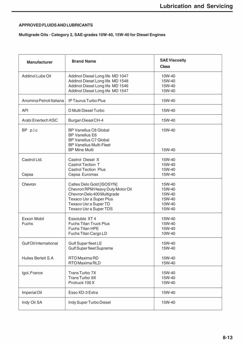
8-13
Lubrication and Servicing
Manufacturer Brand Name SAE Viscosity
Class
Addinol Lube Oil Addinol Diesel Long life MD 1047 10W-40Addinol Diesel Long life MD 1548 15W-40Addinol Diesel Long life MD 1546 15W-40Addinol Diesel Long life MD 1547 15W-40
Anomina Petroli Italiana IP Taurus Turbo Plus 15W-40
API D Multi Diesel Turbo 15W-40
Arabi Enertech KSC Burgan Diesel CH-4 15W-40
BP p.l.c BP Vanellus C6 Global 15W-40BP Vanellus E6BP Vanellus C7 GlobalBP Vanellus Multi-FleetBP Mine Multi 15W-40
Castrol Ltd. Castrol Diesel X 15W-40Castrol Tection T 15W-40Castrol Tection Plus 15W-40
Cepsa Cepsa Euromax 15W-40
Chevron Caltex Delo Gold [ISOSYN] 15W-40Chevron RPM Heavy Duty Motor Oil 15W-40Chevron Delo 400 Multigrade 15W-40Texaco Usr a Super Plus 15W-40Texaco Usr a Super TD 10W-40Texaco Usr a Super TDS 15W-40
Exxon Mobil Essoluble XT 4 15W-40Fuchs Fuchs Titan Truck Plus 15W-40
Fuchs Titan HPE 15W-40Fuchs Titan Cargo LD 10W-40
Gulf Oil International Gulf Super fleet LE 15W-40Gulf Super fleet Supreme 15W-40
Huiles Berleit S.A RTO Maxima RD 15W-40RTO Maxima RLD 15W-40
Igol, France Trans Turbo 7X 15W-40Trans Turbo 9X 15W-40Protruck 100 X 15W-40
Imperial Oil Esso XD-3 Extra 15W-40
Indy Oil SA Indy Super Turbo Diesel 15W-40
APPROVED FLUIDS AND LUBRICANTS
Multigrade Oils - Category 2, SAE-grades 10W-40, 15W-40 for Diesel Engines

8-14
Lubrication and Servicing
Manufacturer Brand Name SAE Viscosity
Class
Indian Oil Corp. Servo Premium (N) 15W-40
Kuwait Petroleum Q8 T 720 10W-40Q8 T 750 15W-40
Lotos Oil Turdus Powertec CI-4 15W-40 15W-40Mauran SAS Turbo land 15W-40OMV AG OMV truck LD 15W-40Pennzoil Products Penn zoil Long. Life Gold 15W-40Pertamina Meditran SMX 15W-40Petro-Canada Lubricants Duron 15W-40
Duron XL Synthetic Blend 15W-40
Petrol Ofisi PO Turbo Dizel Extra 15W-40Petro limex PetrochemicalJoint-Stock Company PLC Diesel SHPD 15W-40 15W-40Prista Oil AD Prista SHPD 15W-40RavensbergerSchmierstoffvertrieb GmbH RAVENOL Mineralo I Turbo Plus SHPD 15W-40Shanghai HIRI Lubricants HIRI 245 15W-40Shell Shell DEO Super 15W-40
Shell Rimula MV 15W-40Shell Rimula R3 X 15W-40Shell Rimula R4 L 15W-40Shell Rimula R T 4 L 15W-40Shell Rimula Super 15W-40Shell Rotella T 15W-40Shell Rotella T Multigrade 15W-40Rimula X CH-4 15W-40
Singapore PetroleumCompany SDM 900, SAE 15W40 15W-40
Sinopec Corp. Great Wall Jinpai Zunlong 15W-40
SRS Schmierstoff VertriebGmbH Winter shall Multi-Rekord top 15W-40
Winter shall Turbo Diesel Plus 15W-40Winter shall TFX 10W-40
Statoil Turbo synt 15W-40Svenska Statoil MaxWay 15W-40Total Antar Milantar PH 15W-40
Antar Milantar PX 15W-40Elf Performance Trophy DX 15W-40Elf Performance Victory 15W-40Fina Kappa Optima 15W-40Total Caprano TDH 15W-40Total Caprano TDI 15W-40Total Rubia TIR 7400 15W-40
Unil Opal Medos 700 15W-40Yacco Inboard 100 4 T Diesel 15W-40

8-15
Lubrication and Servicing
Recommended Lubricant notes
* - Capacities given are approximate, work to dipstick, sightgauges or level plugs.
** - Refer to the 'Lubrication and Service Chart' for thedifferent applications. DO NOT use on the Articulationbearings.
Note 1 - Operation below the minimum temperatures listedfor the oil used without proper pre-heat or warm-up resultsin greatly reduced transmission life. Proper warm-uprequires 20 minutes minimum operation in neutral (withengine at part throttle) before operating the transmission ingear.
Note 2 - Hydraulic Transmission Oil is suitable for use inthe hydraulic system.Typical SAE 10W oils:
SHELL DONAX TEXACO TEXTRAN KUWAIT TO4MOBILTRANS HD BP AUTRAN 4 CASTROL TFCESSO TORQUE FLUID
LUBRICANT GRADE SELECTION GUIDE AT AMBIENT (START-UP) TEMPERATURE
Sm - 637HYDRAULIC OIL
APISAE CODE MIL-SPEC
1 - - MIL-H-5606A
2 DEXRON Auto Trans. Fluid
3 10W CC/CD MIL-L-2104 B/C
4 20W/20 CC/CD MIL-L-2104 B/C
5 30 CC/CD MIL-L-2104 B/C

8-16
Lubrication and Servicing
****
TYRE PRESSURESTyre pressures on this pages apply to the truck serial number range specified only. Gross Vehicle Weight (G.V.W.) and axle weightsmay vary between truck derivatives. Tyre pressure should be recalculated if not shown for a particular truck. Contact TEREX forassistance.
The tyre inflation pressures listed are manufacturers’ recommendations for G.V.W. travelling at maximum speed. TEREX advise thatoperators check tyre inflation pressures with tyre manufacturers to ensure the correct setting for each particular application.
Front Centre RearTruck Brand Size Pattern b lbs/in2 b lbs/in2 b lbs/in2
TA350 Bridgestone 26.5 R25 VLT 4.5 65 5.7 82 5.7 82Michelin 26.5 R25 XADN 3.2 47 4.5 65 4.5 65Michelin 26.5 R25 XADT 3.2 47 4.5 65 4.5 65Double Coin 26.5 R25 REM5 4.5 65 5.5 80 5.5 80Triangle 26.5 R25 TB516 4 58 5.9 86 5.9 86
TA400 Bridgestone 29.5 R25 VLT 4 58 5 73 5 73Bridgestone 29.5 R25 VMT 4 58 5 73 5 73Michelin 29.5 R25 XADN 2.8 40 3.8 55 3.8 55Triangle 29.5 R25 TB516 4 58 4.9 71 4.9 71
TYRE INFLATION PRESSURE

9-1
Technical Data
9 - Technical Data

9-2
Technical Data
This Page Intentionally Left Blank

9-3
Technical Data
TECHNICAL DATA TA350 (A972)
2231
ENGINE
Make/Model........................................................ Detroit Diesel Series 60
Type .......................6 Cylinder, in line , Four cycle diesel, water
cooled, turbocharged with air to air cooling, electronic engine
management.
Gross power at 2 110 rev/min..........................298 kW (400 hp, 405 PS)
Net power at 2 110 rev/min..............................289 kW (388 hp, 393 PS)
Note: Gross power rated to SAE J1995 Jun 90. Engine emission
meets USA EPA Tier 3 /CARB MOH 40 CFR 89 Tier 3 and
proposed EU NRMM (non-road mobile machinery) Tier 3 directive.
Maximum Torque........................2000 Nm (1475 lbf ft) at 1200 rev/min
Number of cylinders/configuration...............................................6, in line
Bore x Stroke..............................................133 x 168 mm (5.24 x 6.61 in)
Piston Displacement........................................................14 l (855 in³)
Air cleaner...........................................................Dry type, double element
Starting...............................................................................................Electric
Maximum Speed (No load)...................................................2300 rev/min
Maximum Speed (Full load).................................................2200 rev/min
Idle Speed................................................................................. 700 rev/min
3 206(10-6)
553(1-10)
3 494(11-5)
1 380(4-6)
3 686(12-1)
2 967(9-9)
2 414(7-11)
3 888(12-9)
3 130(10-3)
3 315(10-11)
6 872(22-7)
2 520(8-3)
1 837(6-0)
66˚
851(2-7)
Dimensions in mm (ft-in)
2 914(9-7)
1 310(4-4)
2 990(9-10)
10 944(35-11)
1 780(5-10)
1 950(6-5)
MaxBodyDepth

9-4
Technical Data
TRANSMISSION
Make/Model..........Allison 4000 Series with integral retarder mounted
directly to the engine, fully automatic transmission with planetary
gearing, lock-up in all gear ranges. Electronic control with six forward
and one reverse gear.
Main......................................................18.5 + 3.4 bar (269 + 50 lbf/in²)
Temperatures:Normal..................................................60 °C - 135° C (140 ° F- 275 °F)
Maximum........................................................................165 ° C (329 ° F)
Ratios:
Transmission .........Refer to the table below
Low Range
Forward
Gear 1 2 3 4 5 6
km/h 5.2 11.0 15.9 24.3 31.0 35.2
mile/h 3.2 6.8 9.9 15.1 19.3 21.9
Reverse
Gear 1
km/h 4.6
mile/h 2.9
High Range
Forward
Gear 1 2 3 4 5 6
km/h 7.9 16.8 24.3 37.1 47.7 53.9
mile/h 4.9 10.4 15.1 23.1 29.6 33.5
Reverse
Gear 1
km/h 7.0
mile/h 4.3
DROPBOX
Remote mounted transfer gearbox taking drive from the transmission
and feeding it via a lockable differential to the front and rear wheels.
Ratios:
Low........................................................1.129:1
High.......................................................0.738:1
Pressure:
High/Low actuation......................15 ± 0.2 bar
Differential lock actuation..............34-50 bar
Lubrication..........................................2 ± 1 bar
Temperature:
Maximum......................................100 °C (212 °F)

9-5
Technical Data
AXLES
Three axles in permanent all-wheel drive (6 X 6) with differential
coupling between each axle to prevent driveline wind-up. Heavy
duty axles with fully-floating axle shafts and outboard planetary
reduction gearing.
Automatic limited slip differentials in each axle. Centre axle
incorporates a through-drive differential to transmit drive to the rear
axle. This differential and the dropbox output differential are locked
simultaneously using one switch selected by the operator.
Ratios:
Differential ........................................ 3.70:1
Planetary .......................................... 6.35:1
Total Reduction .............................. 23.50:1
WHEELS AND TYRES
Wheels:3-piece earthmover rims with 19 stud fixingSize:
Standard............................................25 x 22.00 in for 26.5 R25** tyres
Tyres:
Standard...................................................................................26.5 R25**
Inflation Pressures :
Please refer to page 8-12 for a full list of tyre inflation pressures.
Note: Tyre pressures should be regarded as nominal only. It is
recommended that for tyres both listed and unlisted, the user should
consult the tyre manufacturer and evaluate all job conditions in order
to make the proper selection.
SUSPENSION
Front: Four trailing links and a panhard rod locate the front axle
giving a high roll centre. The optimized front axle position along with
the wide spaced main and rebound mounts, mounted directly above
the axle and long suspension travel, combine with two heavy duty
dampers each side to give excellent handling and ride.
Rear: Each axle is coupled to the frame by three rubber- bushed linkswith lateral restraint by a transverse link. Pivoting inter-axle balance
beams equalize load on each axle. Suspension movement is
cushioned by rubber/metal laminated compression units between
each axle and underside of balance beam ends. Pivot points on
rear suspension linkages are rubber-bushed and maintenance-free.
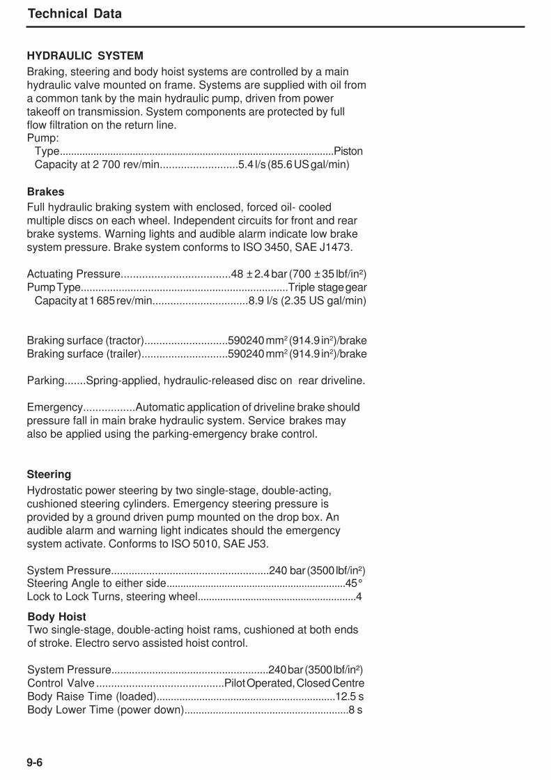
9-6
Technical Data
HYDRAULIC SYSTEM
Braking, steering and body hoist systems are controlled by a main
hydraulic valve mounted on frame. Systems are supplied with oil from
a common tank by the main hydraulic pump, driven from power
takeoff on transmission. System components are protected by full
flow filtration on the return line.Pump:
Type..................................................................................................Piston
Capacity at 2 700 rev/min..........................5.4 l/s (85.6 US gal/min)
Brakes
Full hydraulic braking system with enclosed, forced oil- cooled
multiple discs on each wheel. Independent circuits for front and rear
brake systems. Warning lights and audible alarm indicate low brake
system pressure. Brake system conforms to ISO 3450, SAE J1473.
Actuating Pressure....................................48 ± 2.4 bar (700 ± 35 lbf/in²)
Pump Type.......................................................................Triple stage gear
Capacity at 1 685 rev/min................................8.9 l/s (2.35 US gal/min)
Braking surface (tractor)............................590240 mm2 (914.9 in2)/brake
Braking surface (trailer).............................590240 mm2 (914.9 in2)/brake
Parking.......Spring-applied, hydraulic-released disc on rear driveline.
Emergency.................Automatic application of driveline brake should
pressure fall in main brake hydraulic system. Service brakes may
also be applied using the parking-emergency brake control.
Steering
Hydrostatic power steering by two single-stage, double-acting,
cushioned steering cylinders. Emergency steering pressure is
provided by a ground driven pump mounted on the drop box. An
audible alarm and warning light indicates should the emergency
system activate. Conforms to ISO 5010, SAE J53.
System Pressure......................................................240 bar (3500 lbf/in²)Steering Angle to either side.................................................................45°
Lock to Lock Turns, steering wheel.........................................................4
Body HoistTwo single-stage, double-acting hoist rams, cushioned at both ends
of stroke. Electro servo assisted hoist control.
System Pressure......................................................240 bar (3500 lbf/in²)
Control Valve ...........................................Pilot Operated, Closed Centre
Body Raise Time (loaded)...............................................................12.5 s
Body Lower Time (power down)..........................................................8 s

9-7
Technical Data
SERVICE CAPACITIES
Fuel tank........................................................................481 litre (127 US gal)
Hydraulic System.........................................................330 litre (87.2 US gal)
Engine Crankcase and filters..........................................32 litre (8.4 US gal)Cooling System...............................................................67 litre (17.7 US gal)
Transmission (including cooler)....................................61litre (16.1 US gal)
Dropbox............................................................................. 13 litre (3.4 US gal)
Differential - Front..............................................................33 litre (8.7 US gal)
Differential - Centre..............................................................34 litre (9 US gal)
Differential - Rear...............................................................33 litre (8.7 US gal)
Planetaries (each)............................................................9 litre(2.37 US gal)
Hand Pump Tank..............................................................1 litre (0.26 US gal)
Air Conditioning Compressor ..............................0.125 litre (0.033 US gal)
Brake cooling................................................................175 litre (42.6 US gal)
ELECTRICAL SYSTEM
Type.....................................................................24 volt, Negative Ground
Battery...............................................................Two, 12 Volt, 175 Ah eachAccessories.......................................................................................24 Volt
Alternator.........................................................................................100 Amp
BODY
Of all welded construction, fabricated from high hardness (min. 360 BHN)
1000 MPa (145 000 lbf/in²) yield strength steel. 25° tail chute angle provides
good load retention without tailgate.
Plate Thicknesses:
Floor and Tailchute..........................................................15 mm (0.58 in)
Sides..................................................................................12 mm (0.47 in)
Front.....................................................................................8 mm (0.39 in)
Volume:
Struck (SAE)................................................................15.5 m³ (20.3 yd³)
Heaped 2:1 (SAE)......................................................21.0 m³ (27.5 yd³)
Sound Power Level ISO6395 TA350 TA400
A - Weighted sound power level Lwa in decibels 110 110
Uncertainty Kwa, in decibels 0.66 0.66
Sound Pressure Level at Operators Station ISO6396 TA350 TA400
A - Weighted emission sound pressure level Lpa in decibels 74.5 74.5
Uncertainty Kwa, in decibels 2.4 2.4
The sound level values are in compliance with Directive 2000/14/EC and BS EN 474.
NOISE EMISSIONS
Note: The above result is for the mode giving the highest exterior sound level when measured
and operated as per the prescribed procedures of the standard. Results shown are for the
vehicle in base configuration.
Note: Noise Exposure Level to the operator and bystander personnel may be higher
depending upon proximity to buildings, rock piles, machinery, etc.. The actual job site NoiseExposure Level must be measured and applicable regulations complied with in respect to
Employee Hearing Protection.

9-8
Technical Data
Vehicle Weights 26.5 R25 Tyres
Standard Vehicle kg lb
Net Distribution
Front Axle 15086 32258
Centre Axle 7125 15707
Rear Axle 7068 15582
Vehicle, Net 29279 64547
Payload 34000 74956
Gross Distribution
Front Axle 17279 38094Centre Axle 23000 50705
Rear Axle 23000 50705
Vehicle, Gross 63279 139506
Bare Chassis 23669 52177
Body 4950 10915
Body Hoists (Pair) 660 1455
VIBRATION
Note: The whole body vibrations on
construction machines are influenced by
many factors independent of machine
design, for example ground conditions,
working methods, correct seat adjustment,
operator input to vehicle speed.
The single whole-body emission value listed
above is determined under particular
operating and terrain conditions. In
accordance with EN474, it is not intended tobe used to determine the whole-body
vibration exposure to the operator using this
machine.
Note: It is recognized that the appropriate
design of the operator's seat is the most
effective construction measure to minimize
the whole - body vibration emission of a
particular machine family.
This machine is equipped with an operator's
seat which meets the criteria of EN ISO 7096
representing vertical vibration under severe
operating conditions.
The seat is this machine has been testedwith input spectral class EMI and has a seat
transmissibility factor SEAT > 1.1.
Hands and Arm Vibration
The weighted root mean square acceleration
to which hand and arms of the operator are
exposed is less than 2.5 m/s2 under normaloperating conditions.
Whole body Vibration
Under simulated field duty cycle, the
weighted root mean square acceleration
emission of the machine to which the body is
subjected is less than 0.5 m/s2.

9-9
Technical Data
TECHNICAL DATA TA350 (A975)
2231
ENGINE
Make/Model........................................................ Detroit Diesel Series 60
Type .......................6 Cylinder, in line , Four cycle diesel, water
cooled, turbocharged with air to air cooling, electronic engine
management.
Gross power at 2110 rev/min..........................338 kW (454 hp, 460 PS)
Net power at 2110 rev/min..............................326 kW (437 hp, 443 PS)
Note: Gross power rated to SAE J1995 Jun 90. Engine emission
meets USA EPA Tier 3 /CARB MOH 40 CFR 89 Tier 3 and
proposed EU NRMM (non-road mobile machinery) Tier 3 directive.
Maximum Torque........................2100 Nm (1548 lbf ft) at 1350 rev/min
Number of cylinders/configuration...............................................6, in line
Bore x Stroke..............................................133 x 168 mm (5.24 x 6.61 in)
Piston Displacement...............................................................14 l (855 in³)
Air cleaner...........................................................Dry type, double elementStarting...............................................................................................Electric
Maximum Speed (No load)...................................................2300 rev/min
Maximum Speed (Full load).................................................2200 rev/min
Idle Speed................................................................................. 700 rev/min
3 206(10-6)
553(1-10)
3 494(11-5)
1 380(4-6)
3 686(12-1)
2 967(9-9)
2 414(7-11)
3 888(12-9)
3 130(10-3)
3 315(10-11)
6 872(22-7)
2 520(8-3)
1 837(6-0)
66˚
851(2-7)
Dimensions in mm (ft-in)
2 914(9-7)
1 310(4-4)
2 990(9-10)
10 944(35-11)
1 780(5-10)
1 950(6-5)
MaxBodyDepth
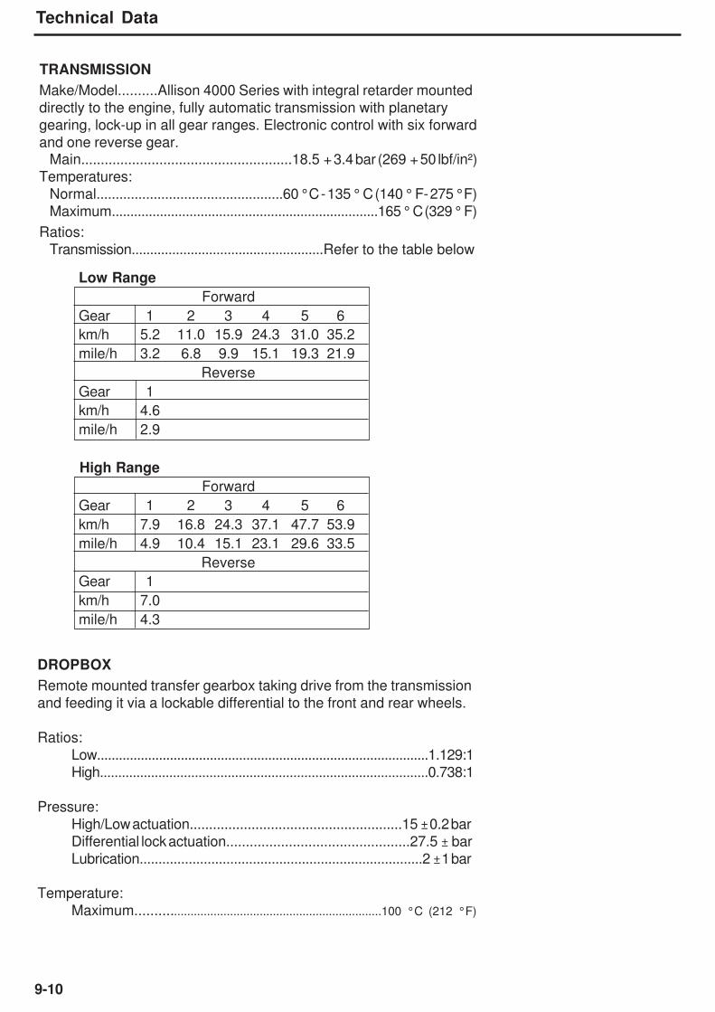
9-10
Technical Data
TRANSMISSION
Make/Model..........Allison 4000 Series with integral retarder mounted
directly to the engine, fully automatic transmission with planetary
gearing, lock-up in all gear ranges. Electronic control with six forward
and one reverse gear.Main......................................................18.5 + 3.4 bar (269 + 50 lbf/in²)
Temperatures:
Normal.................................................60 °C - 135 ° C (140 ° F- 275 °F)
Maximum........................................................................165 ° C (329 ° F)
Ratios:
Transmission....................................................Refer to the table below
Low Range
Forward
Gear 1 2 3 4 5 6
km/h 5.2 11.0 15.9 24.3 31.0 35.2
mile/h 3.2 6.8 9.9 15.1 19.3 21.9
Reverse
Gear 1
km/h 4.6
mile/h 2.9
High Range
Forward
Gear 1 2 3 4 5 6
km/h 7.9 16.8 24.3 37.1 47.7 53.9
mile/h 4.9 10.4 15.1 23.1 29.6 33.5
Reverse
Gear 1
km/h 7.0
mile/h 4.3
DROPBOX
Remote mounted transfer gearbox taking drive from the transmission
and feeding it via a lockable differential to the front and rear wheels.
Ratios:
Low...........................................................................................1.129:1
High..........................................................................................0.738:1
Pressure:
High/Low actuation.......................................................15 ± 0.2 bar
Differential lock actuation...............................................27.5 ± bar
Lubrication...........................................................................2 ± 1 bar
Temperature:
Maximum.........................................................................100 °C (212 °F)

9-11
Technical Data
AXLES
Three axles in permanent all-wheel drive (6 X 6) with differential
coupling between each axle to prevent driveline wind-up. Heavy
duty axles with fully-floating axle shafts and outboard planetary
reduction gearing.
Automatic limited slip differentials in each axle. Centre axle
incorporates a through-drive differential to transmit drive to the rear
axle. This differential and the dropbox output differential are locked
simultaneously using one switch selected by the operator.
Ratios:
Differential ........................................ 3.70:1
Planetary .......................................... 6.35:1
Total Reduction .............................. 23.50:1
WHEELS AND TYRES
Wheels:3-piece earthmover rims with 19 stud fixingSize:
Standard............................................25 x 22.00 in for 26.5 R25** tyres
Tyres:
Standard...................................................................................26.5 R25**
Inflation Pressures :Please refer to page 8-12 for full list of tyre inflation pressures.
Note: Tyre pressures should be regarded as nominal only. It is
recommended that for tyres both listed and unlisted, the user should
consult the tyre manufacturer and evaluate all job conditions in order
to make the proper selection.
SUSPENSION
Front: Four trailing links and a panhard rod locate the front axle
giving a high roll centre. The optimized front axle position along with
the wide spaced main and rebound mounts, mounted directly above
the axle and long suspension travel, combine with two heavy duty
dampers each side to give excellent handling and ride.
Rear: Each axle is coupled to the frame by three rubber- bushed links
with lateral restraint by a transverse link. Pivoting inter-axle balance
beams equalise load on each axle. Suspension movement is
cushioned by rubber/metal laminated compression units between
each axle and underside of balance beam ends. Pivot points on
rear suspension linkages are rubber-bushed and maintenance-free.

9-12
Technical Data
HYDRAULIC SYSTEM
Braking, steering and body hoist systems are controlled by a main
hydraulic valve mounted on frame. Systems are supplied with oil from
a common tank by the main hydraulic pump, driven from powertakeoff on transmission. System components are protected by full
flow filtration on the return line.Pump:
Type..................................................................................................Piston
Capacity at 2 700 rev/min...............................5.4 l/s (85.6 US gal/min)
Brakes
Full hydraulic braking system with enclosed, forced oil- cooled
multiple discs on each wheel. Independent circuits for front and rear
brake systems. Warning lights and audible alarm indicate low brake
system pressure. Brake system conforms to ISO 3450, SAE J1473.
Actuating Pressure....................................48 ± 2.4 bar (700 ± 35 lbf/in²)
Pump Type......................................................................Triple stage gear
Capacity at 1 685 rev/min................................8.9 l/s (2.35 US gal/min)
Braking surface (tractor)............................590240 mm2 (914.9 in2)/brake
Braking surface (trailer).............................590240 mm2 (914.9 in2)/brake
Parking.......Spring-applied, hydraulic-released disc on rear driveline.
Emergency.................Automatic application of driveline brake should
pressure fall in main brake hydraulic system. Service brakes may
also be applied using the parking-emergency brake control.
Steering
Hydrostatic power steering by two single-stage, double-acting,
cushioned steering cylinders. Emergency steering pressure is
provided by a ground driven pump mounted on the drop box. An
audible alarm and warning light indicates should the emergency
system activate. Conforms to ISO 5010, SAE J53.
System Pressure......................................................240 bar (3500 lbf/in²)Steering Angle to either side.................................................................45°
Lock to Lock Turns, steering wheel.........................................................4
Body HoistTwo single-stage, double-acting hoist rams, cushioned at both ends
of stroke. Electro servo assisted hoist control.
System Pressure......................................................240 bar (3500 lbf/in²)
Control Valve ...........................................Pilot Operated, Closed Centre
Body Raise Time (loaded)...............................................................12.5 s
Body Lower Time (power down)..........................................................8 s

9-13
Technical Data
SERVICE CAPACITIES
Fuel tank..................................................................481 litre (127 US gal)
Hydraulic System...................................................330 litre (87.2 US gal)
Engine Crankcase and filters....................................32 litre (8.4 US gal)
Cooling System........................................................67 litre (17.7 US gal)
Transmission (including cooler)..............................61 litre (16.1 US gal)
Dropbox....................................................................... 13 litre (3.4 US gal)
Differential - Front........................................................33 litre (8.7 US gal)
Differential - Centre.......................................................34 litre (9 US gal)
Differential - Rear.......................................................33 litre (8.7 US gal)
Planetaries (each)......................................................9 litre (2.37 US gal)
Hand Pump Tank.......................................................1 litre (0.26 US gal)
Air Conditioning Compressor.........................0.125 litre (0.033 US gal)
Brake cooling.........................................................175 litre (42.6 US gal)
ELECTRICAL SYSTEM
Type.......................................................................24 V, Negative Ground
Battery.................................................................Two, 12 V, 175 Ah each
Accessories..........................................................................................24 V
Alternator.........................................................................................100 Amp
BODY
Of all welded construction, fabricated from high hardness (min. 360
BHN) 1000 MPa (145000 lbf/in²) yield strength steel. 25° tail chute
angle provides good load retention without tailgate.
Plate Thicknesses:
Floor and Tailchute..........................................................15 mm (0.58 in)
Sides..................................................................................12 mm (0.47 in)
Front.....................................................................................8 mm (0.39 in)
Volume:Struck (SAE)..................................................................15.5 m³ (20.3 yd³)
Heaped 2:1 (SAE)........................................................21.0 m³ (27.5 yd³)
Sound Power Level ISO6395 TA350 TA400
A - Weighted sound power level Lwa in decibels 110 110
Uncertainty Kwa, in decibels 0.66 0.66
Sound Pressure Level at Operators Station ISO6396 TA350 TA400
A - Weighted emission sound pressure level Lpa in decibels 74.5 74.5
Uncertainty Kwa, in decibels 2.09 2.09
The sound level values are in compliance with Directive 2000/14/EC and BS EN 474.
NOISE EMISSIONS
Note: The above result is for the mode giving the highest exterior sound level when measured
and operated as per the prescribed procedures of the standard. Results shown are for the
vehicle in base configuration.
Note: Noise Exposure Level to the operator and bystander personnel may be higher
depending upon proximity to buildings, rock piles, machinery, etc.. The actual job site NoiseExposure Level must be measured and applicable regulations complied with in respect to
Employee Hearing Protection.

9-14
Technical Data
Vehicle Weights 26.5 R25 Tyres
Standard Vehicle kg lb
Net Distribution
Front Axle 15086 32258
Centre Axle 7125 15707
Rear Axle 7068 15582
Vehicle, Net 29279 64547
Payload 34000 74956
Gross Distribution
Front Axle 17279 38094
Centre Axle 23000 50705
Rear Axle 23000 50705
Vehicle, Gross 63279 139506
Bare Chassis 23669 52177
Body 4950 10915
Body Hoists (Pair) 660 1455
VIBRATION
Note: The whole body vibrations on
construction machines are influenced by
many factors independent of machinedesign, for example ground conditions,
working methods, correct seat adjustment,
operator input to vehicle speed.
The single whole-body emission value listed
above is determined under particular
operating and terrain conditions. In
accordance with EN474, it is not intended to
be used to determine the whole-body
vibration exposure to the operator using this
machine.
Note: It is recognized that the appropriate
design of the operator's seat is the most
effective construction measure to minimize
the whole - body vibration emission of a
particular machine family.
This machine is equipped with an operator's
seat which meets the criteria of EN ISO 7096
representing vertical vibration under severe
operating conditions.
The seat is this machine has been tested
with input spectral class EMI and has a seat
transmissibility factor SEAT > 1.1.
Hands and Arm Vibration
The weighted root mean square acceleration
to which hand and arms of the operator are
exposed is less than 2.5 m/s2 under normal
operating conditions.
Whole body Vibration
Under simulated field duty cycle, the
weighted root mean square accelerationemission of the machine to which the body is
subjected is less than 0.5 m/s2 .

9-15
Technical Data
ENGINE
Make/Model........................................................ Detroit Diesel Series 60
Type ......................6 Cylinder, in line , Four cycle diesel, water cooled,
turbocharged with air to air cooling, electronic engine management.
Gross power at 2110 rev/min..........................338 kW (454 hp, 460 PS)
Net power at 2110 rev/min..............................326 kW (437 hp, 443 PS)
Note: Gross power rated to SAE J1995 Jun 90. Engine emission
meets USA EPA Tier 3 /CARB MOH 40 CFR 89 Tier 3 and
proposed EU NRMM (non-road mobile machinery) Tier 3 directive.
Maximum Torque........................2100 Nm (1548 lbf ft) at 1350 rev/min
Number of cylinders/configuration...............................................6, in line
Bore x Stroke..............................................133 x 168 mm (5.24 x 6.61 in)
Piston Displacement...............................................................14 l (855 in³)Air cleaner...........................................................Dry type, double element
Starting...............................................................................................Electric
Maximum Speed (No load)...................................................2300 rev/min
Maximum Speed (Full load).................................................2200 rev/min
Idle Speed................................................................................. 700 rev/min
TECHNICAL DATA TA400 (A982)
2230
3 360(11-3)
605(2-0)
3 550(11-8)
1 495(4-11)
3 740(12-3)
3 140(10-4)
2 470(8-1)
3 945(12-11)
3 130(10-3)
3 315(10-11)
6 930(22-9)
2 595(8-6)
1 840(6-0)
66˚
905(2-9)
Dimensions in mm (ft-in)
3 025(9-11)
1 310(4-4)
2 990(9-10)
11 055(36-3)
1 780(5-10)
1 950(6-5)
MaxBodyDepth
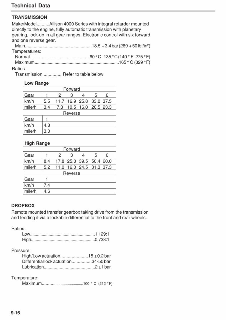
9-16
Technical Data
TRANSMISSION
Make/Model..........Allison 4000 Series with integral retarder mounted
directly to the engine, fully automatic transmission with planetary
gearing, lock-up in all gear ranges. Electronic control with six forward
and one reverse gear.
Main......................................................18.5 + 3.4 bar (269 + 50 lbf/in²)
Temperatures:
Normal..................................................60 °C - 135 °C (140 ° F- 275 °F)
Maximum........................................................................165 ° C (329 °F)
Ratios:
Transmission .............. Refer to table below
Low Range
Forward
Gear 1 2 3 4 5 6
km/h 5.5 11.7 16.9 25.8 33.0 37.5
mile/h 3.4 7.3 10.5 16.0 20.5 23.3
Reverse
Gear 1
km/h 4.8
mile/h 3.0
High Range
Forward
Gear 1 2 3 4 5 6
km/h 8.4 17.8 25.8 39.5 50.4 60.0
mile/h 5.2 11.0 16.0 24.5 31.3 37.3
Reverse
Gear 1
km/h 7.4
mile/h 4.6
DROPBOX
Remote mounted transfer gearbox taking drive from the transmission
and feeding it via a lockable differential to the front and rear wheels.
Ratios:
Low........................................................1.129:1
High.......................................................0.738:1
Pressure:
High/Low actuation......................15 ± 0.2 bar
Differential lock actuation................34-50 bar
Lubrication..........................................2 ± 1 bar
Temperature:
Maximum......................................100 ° C (212 °F)
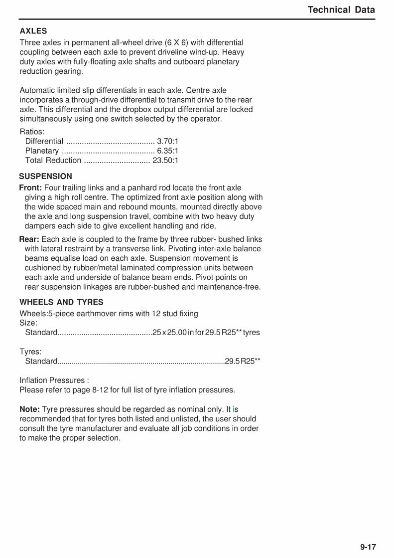
9-17
Technical Data
AXLES
Three axles in permanent all-wheel drive (6 X 6) with differential
coupling between each axle to prevent driveline wind-up. Heavy
duty axles with fully-floating axle shafts and outboard planetary
reduction gearing.
Automatic limited slip differentials in each axle. Centre axle
incorporates a through-drive differential to transmit drive to the rear
axle. This differential and the dropbox output differential are lockedsimultaneously using one switch selected by the operator.
Ratios:
Differential ........................................ 3.70:1
Planetary .......................................... 6.35:1
Total Reduction .............................. 23.50:1
WHEELS AND TYRES
Wheels:5-piece earthmover rims with 12 stud fixingSize:
Standard............................................25 x 25.00 in for 29.5 R25** tyres
Tyres:
Standard...................................................................................29.5 R25**
Inflation Pressures :
Please refer to page 8-12 for full list of tyre inflation pressures.
Note: Tyre pressures should be regarded as nominal only. It is
recommended that for tyres both listed and unlisted, the user should
consult the tyre manufacturer and evaluate all job conditions in order
to make the proper selection.
SUSPENSION
Front: Four trailing links and a panhard rod locate the front axle
giving a high roll centre. The optimized front axle position along with
the wide spaced main and rebound mounts, mounted directly above
the axle and long suspension travel, combine with two heavy duty
dampers each side to give excellent handling and ride.
Rear: Each axle is coupled to the frame by three rubber- bushed linkswith lateral restraint by a transverse link. Pivoting inter-axle balance
beams equalise load on each axle. Suspension movement is
cushioned by rubber/metal laminated compression units between
each axle and underside of balance beam ends. Pivot points on
rear suspension linkages are rubber-bushed and maintenance-free.

9-18
Technical Data
HYDRAULIC SYSTEM
Braking, steering and body hoist systems are controlled by a main
hydraulic valve mounted on frame. Systems are supplied with oil from
a common tank by the main hydraulic pump, driven from power
takeoff on transmission. System components are protected by fullflow filtration on the return line.Pump:
Type..................................................................................................Piston
Capacity at 2700 rev/min..........................5.4 l/s (85.6 US gal/min)
Brakes
Full hydraulic braking system with enclosed, forced oil- cooled
multiple discs on each wheel. Independent circuits for front and rear
brake systems. Warning lights and audible alarm indicate low brake
system pressure. Brake system conforms to ISO 3450, SAE J1473.
Actuating Pressure...................................48 ± 2.4 bar (700 ± 35 lbf/in²)
Pump Type...............................................................Triple stage gear
Capacity at 1 685 rev/min...............................8.9 l/s (2.35 US gal/min)
Braking surface (tractor)............................590240 mm2 (914.9 in2)/brake
Braking surface (trailer).............................590240 mm2 (914.9 in2)/brake
Parking.......Spring-applied, hydraulic-released disc on rear driveline.
Emergency.................Automatic application of driveline brake shouldpressure fall in main brake hydraulic system. Service brakes may
also be applied using the parking-emergency brake control.
Steering
Hydrostatic power steering by two single-stage, double-acting,
cushioned steering cylinders. Emergency steering pressure is
provided by a ground driven pump mounted on the drop box. An
audible alarm and warning light indicates should the emergency
system activate. Conforms to ISO 5010, SAE J53.
System Pressure......................................................240 bar (3500 lbf/in²)Steering Angle to either side.................................................................45°Lock to Lock Turns, steering wheel.........................................................4
Body HoistTwo single-stage, double-acting hoist rams, cushioned at both ends
of stroke. Electro servo assisted hoist control.
System Pressure......................................................240 bar (3500 lbf/in²)
Control Valve ...........................................Pilot Operated, Closed Centre
Body Raise Time (loaded)...............................................................12.5 s
Body Lower Time (power down)...........................................................8 s

9-19
Technical Data
SERVICE CAPACITIES
Fuel tank......................................................................481 litre (127 US gal)
Hydraulic System......................................................330 litre (87.2 US gal)Engine Crankcase and filters......................................32 litre (8.4 US gal)
Cooling System...........................................................67 litre (17.7 US gal)
Transmission (including cooler)............................... 61litre (16.1 US gal)
Dropbox......................................................................... 13 litre (3.4 US gal)
Differential - Front...........................................................33 litre (8.7 US gal)
Differential - Centre............................................................34 litre (9 US gal)
Differential - Rear...........................................................33 litre (8.7 US gal)
Planetaries (each)..........................................................9 litre (2.37 US gal)
Hand Pump Tank............................................................1 litre (0.26 US gal)
Air Conditioning Compressor............................ 0.125 litre (0.033 US gal)
Brake cooling...............................................................175 litre (42.6 US gal)
ELECTRICAL SYSTEM
Type.........................................................................24 V, Negative Ground
Battery..................................................................Two, 12 V, 175 Ah each
Accessories............................................................................................24 V
Alternator.............................................................................................100 A
BODY
Of all welded construction, fabricated from high hardness
(min. 360 BHN) 1000 MPa (145000 lbf/in²) yield strength steel. 25°
tail chute angle provides good load retention without tailgate.
Plate Thicknesses:
Floor and Tailchute..........................................................15 mm (0.58 in)
Sides..................................................................................12 mm (0.47 in)
Front.....................................................................................8 mm (0.39 in)
Volume:
Struck (SAE)..................................................................17.4 m³ (22.8 yd³)
Heaped 2:1 (SAE)........................................................23.3 m³ (30.3 yd³)
Sound Power Level ISO6395 TA350 TA400
A - Weighted sound power level Lwa in decibels 110 110
Uncertainty Kwa, in decibels 0.66 0.66
Sound Pressure Level at Operators Station ISO6396 TA350 TA400
A - Weighted emission sound pressure level Lpa in decibels 74.5 74.5
Uncertainty Kwa, in decibels 2.09 2.09
The sound level values are in compliance with Directive 2000/14/EC and BS EN 474.
NOISE EMISSIONS
Note: The above result is for the mode giving the highest exterior sound level when measured
and operated as per the prescribed procedures of the standard. Results shown are for the
vehicle in base configuration.
Note: Noise Exposure Level to the operator and bystander personnel may be higher
depending upon proximity to buildings, rock piles, machinery, etc.. The actual job site Noise
Exposure Level must be measured and applicable regulations complied with in respect to
Employee Hearing Protection.
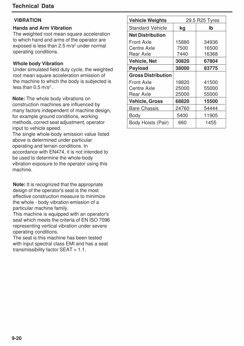
9-20
Technical Data
Vehicle Weights 29.5 R25 Tyres
Standard Vehicle kg lb
Net Distribution
Front Axle 15880 34936
Centre Axle 7500 16500
Rear Axle 7440 16368
Vehicle, Net 30820 67804
Payload 38000 83775
Gross Distribution
Front Axle 18820 41500
Centre Axle 25000 55000
Rear Axle 25000 55000
Vehicle, Gross 68820 15500
Bare Chassis 24760 54444
Body 5400 11905
Body Hoists (Pair) 660 1455
VIBRATION
Note: The whole body vibrations on
construction machines are influenced by
many factors independent of machine design,
for example ground conditions, working
methods, correct seat adjustment, operator
input to vehicle speed.
The single whole-body emission value listed
above is determined under particular
operating and terrain conditions. In
accordance with EN474, it is not intended to
be used to determine the whole-body
vibration exposure to the operator using this
machine.
Note: It is recognized that the appropriate
design of the operator's seat is the most
effective construction measure to minimize
the whole - body vibration emission of a
particular machine family.
This machine is equipped with an operator's
seat which meets the criteria of EN ISO 7096
representing vertical vibration under severe
operating conditions.
The seat is this machine has been tested
with input spectral class EMI and has a seat
transmissibility factor SEAT > 1.1.
Hands and Arm Vibration
The weighted root mean square acceleration
to which hand and arms of the operator are
exposed is less than 2.5 m/s2 under normal
operating conditions.
Whole body Vibration
Under simulated field duty cycle, the weighted
root mean square acceleration emission of
the machine to which the body is subjected is
less than 0.5 m/s2 .

10-1
Symbol Identification
10 - Symbol Identification

10-2
Symbol Identification
This Page Intentionally Left Blank
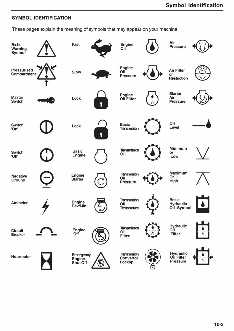
10-3
Symbol Identification
SYMBOL IDENTIFICATION
These pages explain the meaning of symbols that may appear on your machine.
PressurisedCompartment
MasterSwitch
Switch'On'
Switch'Off'
NegativeGround
Ammeter
CircuitBreaker
Hourmeter
Basic WarningSymbol
Fast
Slow
Lock
Lock
BasicEngine
EngineStarter
EngineRev/Min
Engine'Off'
EmergencyEngineShut Off
EngineOil
EngineOilPressure
EngineOil Filter
BasicTransmission
TransmissionOil
TransmissionOilPressure
TransmissionOilTemperature
TransmissionOilFilter
TransmissionConvertorLockup
AirPressure
Air FilterorRestriction
StarterAirPressure
OilLevel
Minimumor Low
MaximumOrHigh
BasicHydraulicOil Symbol
HydraulicOil Filter
HydraulicOil FilterPressure

10-4
Symbol Identification
P
S
N
HotHydraulic
CoolantTemperature
Coolant cold'
CoolantHot
Cooling
Heating
Fuel GaugeOrFill tube
Fuel Filter
FuelShut-Off
BasicLightsSymbol
Light Flood
Light LowBeam
Light HighBeam
InstrumentPanel Light
Lamp Test
Horn
WindshieldWiper
WindshieldDefroster
WindshieldWasher
Blower Fan
Heater
AirConditioner
InsideAirCirculation
OutsideAir
ParkingBrake
Parking Brake
Brake OilTemperature
Turn Left
Turn Right
Tilt Steering
Low SteeringPressure
High SpeedOr Level
Low SpeedOr Level
Body Up
Body 'Raise'
Body 'Hold'
Body'Lower'
Body'Float'
Neutral
Dumpertruck'Retarder'
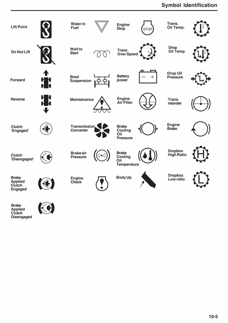
10-5
Symbol Identification
STOP
H
L
Lift Point
Do Not Lift
Forward
Reverse
Clutch'Engaged'
Clutch'Disengaged'
BrakeAppliedClutchEngaged
BrakeAppliedClutchDisengaged
Water inFuel
Wait toStart
BowlSuspension
Maintainance
TransmissionConverter
Brake airPressure
EngineCheck
EngineStop
TransOver Speed
Batterypower
EngineAir Filter
BrakeCoolingOilPressure
BrakeCoolingOilTemperature
Body Up
Trans.Oil Temp.
DropOil Temp
Drop OilPressure
Trans.retarder
EngineBrake
DropboxHigh Ratio
DropboxLow ratio

10-6
Symbol Identification
NOTES

10-7
Symbol Identification
NOTES

10-8
Symbol Identification
NOTES
Top Related