


Languages
Pages
Legal

Temperature products, recorders & system componentsQuality instruments you can rely on
Products Solutions Services

2 Temperature products, recorders and system components
Contents
Technical reference 28 Thermowell design 29 Insert technologies 30 Process connections 32 Thermowell materials34 RTD information 35 Thermocouple information 36 Terminal heads 37 Temperature transmitter
configuration 38 Pipe dimensions 40 Conversion factors 41 IP ratings 42 Hazardous areas
Experts in temperature 3 Endress+Hauser -
experts in temperature 4 Modular concept
Sensors without thermowell 6 General purpose
thermometers 7 Compact thermometers
Modular thermometers 8 Approvals/certificates/testsfor
TM401 & TM411 9 Aseptic and
hygienic thermometers 10 General-purpose thermometers 12 Heavy duty thermometers 13 Heavy duty transmitters 14 Thermowells 16 High temperature thermometers17 Sensor inserts18 Certificationandtesting
Electronics 20 Temperature transmitters 22 Transmitter accessories, barriers
and HART communication device 23 Data managers 24 Process indicators 25 Multifunction displays
Temperature engineering 26 Flexible multipoint thermometers 27 Rigid multipoint thermometers

3
Endress+Hauser - experts in temperature
Drawing on considerable international experience and with accredited calibration laboratories (DKD, SIT), our global network of production facilities and representatives support our customers in over 120 countries.
Our production centres manufacture around 7,000 temperature assemblies and transmitters every week to supply Endress+Hauser customers around the globe.
Endress+Hauser’s quality management system is accredited to ISO 9001:2008 and the scope of supply covers the design and manufacture of thermowells and industrial temperature sensors. Recognising our customers’ requirements for quality, we provide temperature measurement points with individual
component parts subject to careful examination in our own test centres. The quality of materials, processes and instrumentsisfullycertifiedandspecificdetails can be traced back for years!
Our business park in Manchester houses our Centre of Competence for engineered temperature solutions with extensive temperature manufacturing and testing facilities. Within our state-of-the-art Application, Training and Engineering Centre we have calibration and training facilities tailor-made for our customers. Our key personnel have over 80 years of experience and are familiar with all aspects of temperature design and manufacturing techniques to provide an accredited quality service across the UK.
Experts in temperature
With unprecedented experience and extensive manufacturing facilities the world over, Endress+Hauser is recognised as a specialist in temperature measurement technology. We specialise in the design and manufacture of industrial temperature sensors and bespoke engineered solutions tailored to our customers’ needs across all industries.

4 Temperature products, recorders and system components
Modular components, modular specification
Ergonomically designed terminal head with clear labelling to identify spare parts and approvals, including serial number for complete traceability.
High purity mineral insulated insert with serial number, temperature range and length clearly labelled.
Terminationintoterminalblock,flyingleadsor one of our range of electronic temperature transmitters, which again carries its own serial number.
Any testing carried out on the thermowell will be recorded against the assembly’s serial number, which is clearly marked on the thermowell.
All our temperature sensors are individually part numbered. This allows you to specify exact lengths, diameters, housings, terminations and many other attributes. Details of products can be found on our technical information sheets available for download at www.uk.endress.com. Furthermore, each component of the modular thermometer can be supplied individually as a spare part.
5
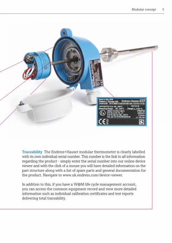
Traceability The Endress+Hauser modular thermometer is clearly labelled with its own individual serial number. This number is the link to all information regarding the product - simply enter the serial number into our online device viewer and with the click of a mouse you will have detailed information on the part structure along with a list of spare parts and general documentation for the product. Navigate to www.uk.endress.com/device-viewer.
In addition to this, if you have a W@M life cycle management account, you can access the common equipment record and view more detailed informationsuchasindividualcalibrationcertificatesandtestreportsdelivering total traceability.
Modular concept

6 Temperature products, recorders and system components
• Economicoption• Separatethermowell• ThermocoupleorRTD• Configurableoptions
• Cost-effective • Selectable dimensions• Optional fitting• Mineral insulated
sheath
• Cost-effective • Selectable dimensions• Optional fitting• Mineral insulated
sheath
• Cost-effective • Selectable dimensions• Stainless steel or
PTFE olive• Straight, reduced or
tapered
Cable sensor Sensor with housing Tube thermowell
General-purpose thermometers
RTDT/C
TST310 TSC310
TR24TEC420
TW251
Typical applications
• General light industrial• For extra long lengths• Where space is limited• Thermal profiling
• General light industrial• When a thermowell is
not needed
• General light industrial
• -200 to 600/1100°C• Up to 40 bar• t90 from ≤2.0s• Optional,
compression type• RTD or thermocouple
• -200 to 600/1100°C• Up to 50 bar• t90 from ≤2.0s• Optional,
compression type• RTD or thermocouple
• 600°C• Up to 50 bar
• Screwed/weld-in
Features
General-purpose thermometers
Technical data• Temperature• Pressure• Response time• Connection
• Sensing element

7
• 316stainlesssteelhousing• Fastresponsetip• Integralelectronics• PCprogrammable• Quickresponseasstandard
• Integral transmitter (optional)• Pt100 or 4-20mA output• 3-A compliant (TMR35)• M12 plug connection• Selectable dimensions
• Integral display• 2 x PNP or 1 x PNP + 4-20mA output• 3-A compliant (TTR35)• M12 plug connection• Selectable dimensions
Technical data• Temperature• Pressure• Response time• Connection• Sensing element• Supply voltage
Compact thermometer Compact display/switch
Compact thermometers
TMR31 TMR35
TTR31 TTR35
• -50 to 200°C with neck• 30 bar (depending on connection)• t90 ≤2.0s• TMR31 screwed/TMR35 hygienic• Pt100, 4-wire, class A• 10 to 35V DC
• -50 to 200°C with neck• 30 bar (depending on connection)• t90 ≤2.0s• TTR31 screwed/TTR35 hygienic• Pt100, 4-wire, class A• 12 to 30V DC
Typical applications
• Food and beverage• Energy monitoring• Light chemical/life science• General process
• Food and beverage• Energy monitoring• Light chemical/life science• General process
Features
RTD
Sensors without thermowell
Compact thermometers
8 Temperature products, recorders and system components
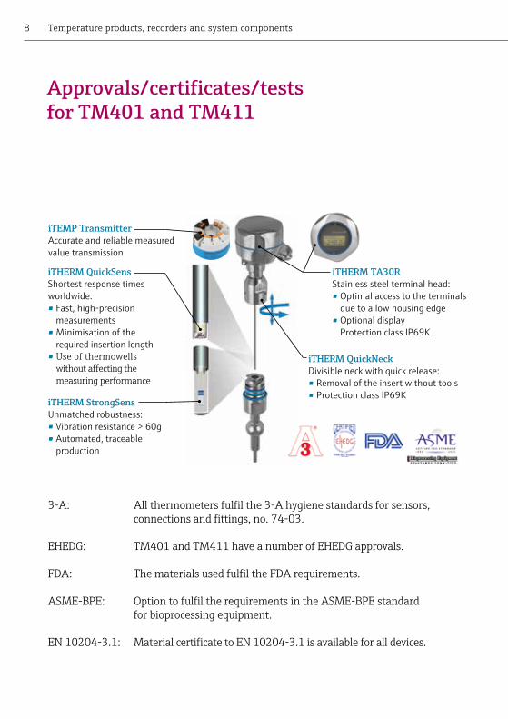
Approvals/certificates/tests for TM401 and TM411
3-A: Allthermometersfulfilthe3-Ahygienestandardsforsensors, connectionsandfittings,no.74-03.
EHEDG: TM401 and TM411 have a number of EHEDG approvals.
FDA: ThematerialsusedfulfiltheFDArequirements.
ASME-BPE: OptiontofulfiltherequirementsintheASME-BPEstandard for bioprocessing equipment.
EN10204-3.1: MaterialcertificatetoEN10204-3.1isavailableforalldevices.
Sam to send elements to
recreate
iTHERM QuickSensShortest response times worldwide:• Fast, high-precision
measurements• Minimisation of the
required insertion length• Use of thermowells withoutaffectingthe measuring performance
iTHERM StrongSensUnmatched robustness:• Vibration resistance > 60g• Automated, traceable
production
iTHERM TA30RStainless steel terminal head:• Optimal access to the terminals
due to a low housing edge• Optional display
Protection class IP69K
iTHERM QuickNeckDivisible neck with quick release:• Removal of the insert without tools• Protection class IP69K
iTEMP TransmitterAccurate and reliable measured value transmission
9Modular thermometers
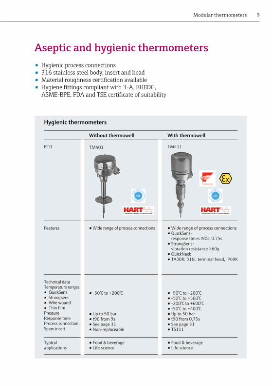
• Hygienicprocessconnections• 316stainlesssteelbody,insertandhead• Materialroughnesscertificationavailable• Hygienefittingscompliantwith3-A,EHEDG, ASME-BPE,FDAandTSEcertificateofsuitability
• Wide range of process connections • Wide range of process connections • QuickSens-
response times t90s: 0.75s• StrongSens-
vibration resistance >60g• QuickNeck • TA30R: 316L terminal head, IP69K
Technical dataTemperature ranges• QuickSens• StrongSens• Wire wound• Thin filmPressureResponse timeProcess connectionSpare insert
Without thermowell With thermowell
Hygienic thermometers
TM401 TM411
• -50°C to +200°C
• Up to 50 bar• t90 from 9s• See page 31• Non-replaceable
• -50°C to +200°C• -50°C to +500°C• -200°C to +600°C• -50°C to +400°C• Up to 50 bar• t90 from 0.75s• See page 31• TS111
Typical applications
• Food & beverage• Life science
• Food & beverage• Life science
Features
RTD
Aseptic and hygienic thermometers

10 Temperature products, recorders and system components
• Insertinsidethermowell• Hazardousareaoption• Configurabledimensions• Forspareinsertsseepage17
General-purpose thermometers
• Integral thermowell• Mineral insulated
sensor• Screw thread• With lagging extension
• Integral thermowell• Mineral insulated
sensor• Screw thread• Fitting under head
• Integral thermowell• Mineral insulated
sensor• Optional fittings• Without cooling neck
With cooling neck Without cooling neck Separate fitting
TR10TC10
TR11 TR12TC12
• General process• Chemical• Hazardous areas
• General process• Chemical• Hazardous areas
• General process• Chemical• Hazardous areas
• -200 to 600°C/1100°C• Up to 50 bar• t90 from ≤13.0s
• Thread ½" to 1"• TPR100/TPC100
• -200 to 600°C/1100°C• Up to 50 bar• t90 from ≤13.0s
• Thread ½" to ¾"• TPR100/TPC100
• -200 to 600°C/1100°C• Up to 50 bar• t90 from ≤13.0s
• Supplied separately • TPR100/TPC100
Typical applications
Technical data• Temperature• Pressure• Response
time• Connection• Spare insert
Features
General-purpose thermometers
RTDT/C

11Modular thermometers
• Integral thermowell• Mineral insulated sensor• Welded flange• With cooling neck
• Integral thermowell• Mineral insulated sensor• Flanged or weld-in• With cooling neck
• To fit into existing thermowell
• Mineral insulated sensor• Screw thread• With cooling neck
Flanged DIN form 4 or 4F Without thermowell
TR13TC13
TR15TC15
TR88TC88
• General process• Chemical• Hazardous areas
• General process• Chemical• Hazardous areas
• General process• Chemical• Hazardous areas
• -200 to 600°C/1100°C• Up to 100 bar• t90 from ≤13.0s• Flange up to 2"• TPR100/TPC100
• -200 to 600°C/1100°C• Up to 400 bar• t90 from ≤18.0s• Flange or weld-in• TPR100/TPC100
• -200 to 600°C/1100°C• Dependent on thermowell• Insert only, t90 from ≤2.0s• Thread ½", M14, M18• TPR100/TPC100

12 Temperature products, recorders and system components
• Hazardousareaoption• Optional316stainlesssteelhousing• Configurabledimensions• Forspareinsertseepage17
Heavy duty thermometers
• Replaceable insert• Mineral insulated
sensor• Robust design• To fit into existing
thermowell
• Replaceable insert• Mineral insulated
sensor• Robust design • Welded flange or
screwed thread
• Replaceable insert• Mineral insulated
sensor• Robust design • With barstock
thermowell
Without thermowell
Tube thermowellscrewed or flanged
Solid drilled thermowellscrewed or flanged
Heavy duty thermometers
RTDT/C
TR62TC62
TR63 TC63
TR66 TC66
Typical applications
• Oil & gas• Petrochemical• Heavy industry• Hazardous areas
• Oil & gas• Petrochemical• Heavy industry• Hazardous areas
• Oil & gas• Petrochemical• Heavy industry• Hazardous areas
• -200 to 600°C/1100°C• Dependent on thermowell• Insert only,
t90 from ≤2.0s• Screwed to suit
thermowell• TPR300/TPC300
• -200 to 600°C/1100°C• Up to 100 bar• Insert only,
t90 from ≤2.0s• Screwed or flanged
• TPR300/TPC300
• -200 to 600°C/1100°C• Up to 500 bar• Insert only,
t90 from ≤2.0s• Screwed or flanged
• TPR300/TPC300
Features
Technical data• Temperature• Pressure• Response
time• Fitting
• Spare insert

13Modular thermometers
• Insertanddisplayonly• Hazardousareaoption• Seepages14and15forthermowells• Forspareinsertseepage17• Optional316stainlesssteelhousing
Heavy duty transmitters
• Replaceable insert• Mineral insulated sensor• Robust design• 316 stainless steel housing option • Transmitter with single chamber • Optional display
• Replaceable insert • Mineral insulated sensor• Robust design • 316 stainless steel housing option• Transmitter with dual chamber display • Optional display
Technical data• Temperature• Pressure• Response time• Fitting• Spare insert• Supply voltage
Single chamber Dual chamber
Compact thermometers
TMT142RTMT142C
TMT162RTMT162C
• -200 to 600°C/1100°C• Dependent on thermowell• Insert only from t90 ≤2.0s• Screwed to suit thermowell• TET300/TEC300• 11 to 40V DC
• -200 to 600°C/1100°C• Dependent on thermowell• Insert only from t90 ≤2.0s• Screwed to suit thermowell• TET300/TEC300• 11 to 40V DC
Typical applications
• Oil & gas• Petrochemical• Heavy industry• Hazardous areas
• Oil & gas• Petrochemical• Heavy industry• Hazardous areas
Features
RTDT/C

14 Temperature products, recorders and system components
• Cost-effective• Reduced tip option for fast response• Greater immersed lengths• Quick turnaround
• Drilled and machined from solid bar• Partial or full penetration flange welds• Can be straight, tapered or stepped
Tubular up to 100 bar Barstock up to 500 bar
• Stainless steel• Alloy C276, C22• Nickel alloys
• Stainless steel• Alloy C276, C22• Duplex, Super Duplex• 6 Moly• Nickel alloys
• Up to 1100°C• Up to 100 bar• Screwed or flanged• EN, ANSI
• Up to 1100°C• Up to 500 bar• Screwed or flanged• EN, ANSI, API
Typical materials
Technical data• Temperature• Pressure• Fitting• Flange style
Features
Thermowells
• Engineeredsolutions• Availableinexoticmaterials• Widerangeofprocessconnections• Non-destructivetestingavailable
Thermowells
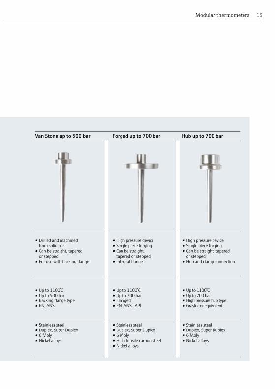
15Modular thermometers
• Drilled and machined from solid bar
• Can be straight, tapered or stepped
• For use with backing flange
• High pressure device• Single piece forging• Can be straight,
tapered or stepped• Integral flange
• High pressure device• Single piece forging• Can be straight, tapered
or stepped• Hub and clamp connection
Van Stone up to 500 bar Forged up to 700 bar Hub up to 700 bar
• Stainless steel• Duplex, Super Duplex• 6 Moly• Nickel alloys
• Stainless steel• Duplex, Super Duplex• 6 Moly• High tensile carbon steel• Nickel alloys
• Stainless steel• Duplex, Super Duplex• 6 Moly• Nickel alloys
• Up to 1100°C• Up to 500 bar• Backing flange type• EN, ANSI
• Up to 1100°C• Up to 700 bar• Flanged• EN, ANSI, API
• Up to 1100°C• Up to 700 bar• High pressure hub type• Grayloc or equivalent

16 Temperature products, recorders and system components
• Highresistancetoarduousconditions• Replaceableinsert• Configurablelengthsanddiameters• Varioussheathcombinations• Seepage32and33inthereferencesectionforlistofmaterials
High temperature thermometers
• Thermocouple types K, J, N, R, S or B
• Ceramic insulators• Single sheath• C610(RA), SiC and Sin
• Thermocouple types R, S or B
• Ceramic insulators• Single, double or
triple sheath• C610(RA), C799 (AP)
• Thermocouple type K, J, N or S
• Ceramic or mineral insulated sheath
• Various metallic sheaths available
Refractory sheathedup to 1200°C
Refractory sheathedup to 1700°C
Metallic sheathedup to 1200°C
High temperature thermometers
T/C TAF11 TAF12 TAF16
Typical applications
• High temperature ovens• Industrial furnaces
• High temperature ovens• Industrial furnaces• High temperature kilns• Incinerators
• High temperature ovens• Industrial furnaces• Rotary kilns• Incinerators
• Up to 1200°C defined by T/C type
• Up to 1 bar• Optional adjustable
flange 70mm• TPC 200
• Up to 1700°C defined by T/C type
• Up to 1 bar• Optional adjustable
flange 70mm• TPC 200
• Up to 1200°C
• Up to 50 bar• Adjustable flange/
compression fitting• TPC 200
Features
Technical data• Temperature • Pressure• Fitting • Spare insert

17Modular thermometers
• Spareinsertsformodularthermometers• ThermocoupleorRTDversions• Hazardousareaoption• Suppliedwithterminalblock,transmitterorflyingleads• QuickSens,StrongSens
Sensor inserts
• Standard replacement sensor
• Hazardous area option
• Configurable dimensions
• With block, transmitter or leads
• Hygienic replacement sensor
• Hazardous area option
• Configurable dimensions
• With block, transmitter or leads
• For ATEX Ex d units
• Integral flame path collar
• Configurable dimensions
• With block, transmitter or leads
• Sprung replacement sensor
• Hazardous area option
• Configurable dimensions
• With leads only
Standard insert i
Standard Insert
Standard insert
Spring loaded nipple
Sensor inserts
RTDT/C
TPR100TPC100
TS111 TPR300 TPC300
TET300TEC300
• TR10, 11, 12, 13, 15, 88
• TC10, 12, 13, 15, 88
• TM411 • TR62, 63, 66• TC62, 63, 66
• TMT142R, 142C • TMT162R, 162C
• -200 to 600/ 1100°C
• Dependent on thermowell
• t90 from ≤2.0s• DIN plate • RTD or
thermocouple• 3mm, 6mm
• -200 to 600°C • Dependent on
thermowell• t90 from 0.75s• DIN plate • RTD, QuickSens,
StrongSens.• 3mm, 6mm
• -200 to 600/ 1100°C
• Dependent on thermowell
• t90 from ≤2.0s• Spring loaded
nipple• RTD or
thermocouple• 6mm
Features
Technical data• Temperature
• Pressure
• Response time• Fitting
• Sensing element
• Insert Dia
Replacement insert for
• -200 to 600/ 1100°C
• Dependent on thermowell
• t90 from ≤2.0s• DIN plate with
flame path collar• RTD or
thermocouple• 3mm, 6mm

18 Temperature products, recorders and system components
Several methods of non-destructive testing can be performed to guarantee components are free from material joint problems such as cracks, pores and cavities.
Calibrations can be performed in our laboratory and are traceable to national standards to certify the accuracy of our thermometers.
Certification and testingIndividual components of instruments are subject to careful examination in our own test centres. The quality of the materials used in manufacture arefullycertifiedandtraceable.
19
TZC134Traceable calibration
Calibrated using certified equipment traceable to ISO/IEC 17025, DKD and SIT guidelines for internationally recognised calibration certificates.
TZC133Primary calibration
Calibrated in our own accredited laboratories to ISO/IEC 17025, DKD and SIT guidelines for internationally recognised calibration certificates.
TZC150Evaluation report
Issued in lieu of calibration certificate if the immersion length of the sensor is too short for full calibration.
TZC130Certificate of conformity
Issued by the Endress+Hauser quality department to certify that the goods supplied conform to the customer purchase order.
TZC131Material certificate 3.1
The inspection certificate EN 10204 3.1 for wetted parts.
TZC138Hydrostatic test
Using internal or external pressure test the strength and pressure rating of thermowells and process connections can be verified.
TZC125Dye penetrant
Suitable for checking material surfaces and welded joints for surface breaking defects such as forging defects or cracks.
TZC161PMI
Positive Material Identification. Non-destructive X-ray fluorescence (XRF) to verify the chemical composition of the materials.
TZCB01Radiographic test
Hidden faults like inclusions, pores, tears, etc in the base material and/or in the weld are identified. Furthermore, the exact positioning of the welded components can be checked.
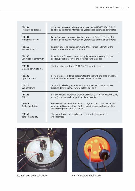
Ice bath zero point calibration High temperature calibration
TZC140Bore concentricity
Thermowell stems are checked for concentricity to guarantee wall thickness.
Certification and testing

20 Temperature products, recorders and system components
• No ATEX rating • PC
programmable
• Hazardous area option
• PC programmable
• Hazardous area option
• SIL2 compliant
• Hazardous area option
• Display interface• Dual input• SIL2/3
Economical Galvanic isolation
HART protocol HART protocol
Temperature transmitters
TMT180 TMT181 TMT182 TMT82
• RTD• 0.1K/0.08% of
span• PC
• No
• 10 to 35V DC• No• No
• RTD, T/C, Ω, mV • 0.2K/0.08% of
span• PC
• 3.75kV AC
• 8 to 35V DC• No• Yes
• RTD, T/C, Ω, mV • 0.2K/0.08% of
span • HART
• 2kV AC
• 11 to 35V DC• No• Yes
• RTD, T/C, Ω, mV• 0.1K
• HART
• 2kV AC
• 9 to 32V• TID10 (plug on display)• Yes
Features
Technical data• Input• Accuracy
(Pt100)• Interface
• Galvanic isolation
• Power supply• Display• DIN rail
version
Interface
• DINstandardheadmount• DINrailmountoptionavailable(notshown)• Optionaldisplays• Varietyofinterfacemethods• ImprovedaccuracyviasensormatchingorCalendervanDusenequation
Temperature transmitters
21
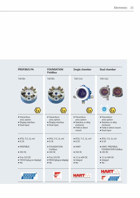
• Hazardous area option
• Display interface• Dual input
• Hazardous area option
• Display interface• Dual input
• Hazardous area option
• Stainless or alloy enclosure
• Field or direct mount
• Hazardous area option
• Stainless or alloy enclosure
• Field or direct mount• Dual input
PROFIBUS PA FOUNDATION Fieldbus
Single chamber Dual chamber
TMT84 TMT85 TMT142 TMT162
• RTD, T/C, Ω, mV • 0.1K
• PROFIBUS
• 2kV AC
• 9 to 32V DC• TID10 (plug on display)• No
• RTD, T/C, Ω, mV • 0.2K
• HART
• 2kV AC
• 11 to 40V DC• Integral• No
• RTD, T/C, Ω, mV • 0.1K
• HART, PROFIBUS, FOUNDATION Fieldbus
• 2kV AC
• 11 to 40V DC• Integral• No
Electronics
• RTD, T/C, Ω, mV • 0.1K
• FOUNDATION Fieldbus
• 2kV AC
• 9 to 32V DC• TID10 (plug on display)• No

22 Temperature products, recorders and system components
• Varietyofinterfacemethods• On-siteprogrammingofinstruments• Compatiblewithawiderangeofdevices• Easytouse
Transmitter accessories, barriers and HART communication device
• Communication device for Endress+Hauser transmitters and electronic modules
• USB port to standard Endress+Hauser service port connection
• Allows users to reconfigure existing devices or keep common stock and configure as needed
• Non Ex only
• RN221 – Intrinsically safe power supply, galvanic isolation of loop
• HART status monitor with alarm relay, set-up using front mounted sockets
• RB223 – As above but does not require power supply, bidirectional HART transmission and applications up to SIL 3
• Plug-on interface unit with dot-matrix display
• 12 DIP switches on underside for configuration of TMT84
• Process display when assembled with suitable terminal head for TMT82, TMT84 & TMT85
• Handheld communication device for the configuration of HART protocol electronic modules
• Wireless communication via BluetoothTM or WLAN based on an industrial PDA
• Device Xpert Configuration software package for field device commissioning, diagnosis and maintenance
Common Device Interface
Active/passive barrier
Plug-on display
Field Xpert
Transmitter accessories, barriers and HART communication device
TXU10 RN221/ RB223 TID10 SFX370
Features
None EX version SFX350
23Electronics
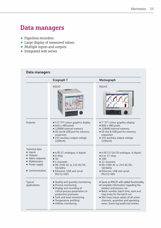
• Paperlessrecorders• Largedisplayofmeasuredvalues• Multipleinputsandoutputs• Integratedwebserver
Data managers
• 5.5” TFT colour graphics display• 640 x 480 pixels• 128MB internal memory• SD slot & USB port for memory
expansion• 24V auxiliary output voltage
(200mA)
• 7” TFT colour graphics display• 800 x 480 pixels• 128MB internal memory• SD slot & USB port for memory
expansion• 24V auxiliary output voltage
(200mA)
Technical data• Inputs• Outputs• Alarm setpoints• Mathematics• Power supply
• Communication
Ecograph T Memograph
Data managers
RSG35 RSG40
• 4/8/12 analogue, 6 digital• 6 relay• 30• 4 channels• 90-250V AC or 24V AC/DC,
50/60Hz• Ethernet, USB and serial
RS232/485
• 4/8/12/16/20 analogue, 6 digital• 6 or 12 relay• 100• 12 channels• 90-250V AC or 24V AC/DC,
50/60Hz• Ethernet, USB and serial
RS232/485
Typical applications
• Quality and quantity monitoring• Process monitoring • Display and recording of
critical process parameters in production processes
• Tank and level monitoring• Temperature profiling• Utilities monitoring
• Same as RSG35 with added functionality• Complete information regarding the
product and process run• Batch number, batch time, start and
stop times for the batch run• Min/max/mean values of all active
channels, quantities and operating times. Event log/audit trail entries
Features
24 Temperature products, recorders and system components
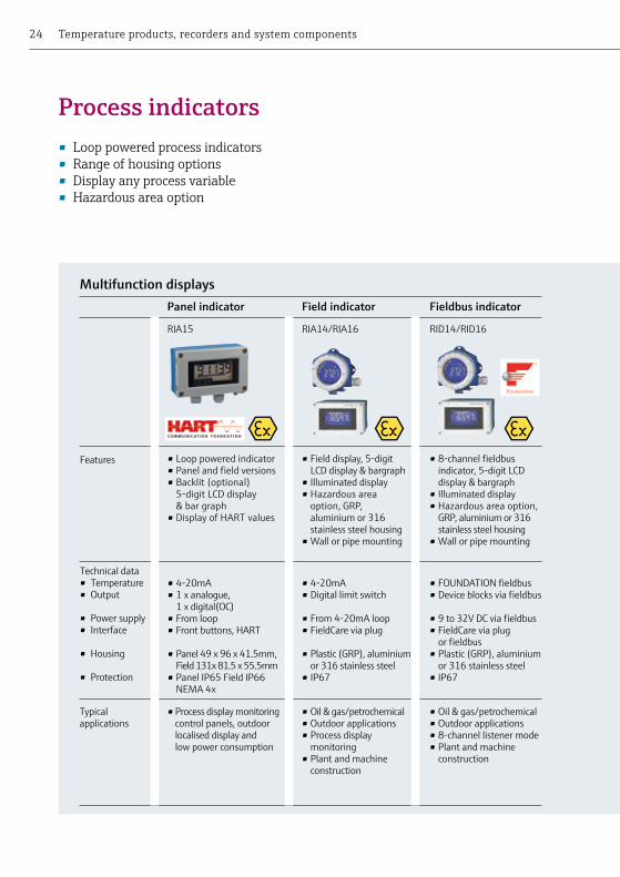
• Looppoweredprocessindicators• Rangeofhousingoptions• Displayanyprocessvariable• Hazardous area option
• Loop powered indicator • Panel and field versions• Backlit (optional)
5-digit LCD display & bar graph
• Display of HART values
• Field display, 5-digit LCD display & bargraph
• Illuminated display • Hazardous area
option, GRP, aluminium or 316 stainless steel housing
• Wall or pipe mounting
• 8-channel fieldbus indicator, 5-digit LCD display & bargraph
• Illuminated display • Hazardous area option,
GRP, aluminium or 316 stainless steel housing
• Wall or pipe mounting
Panel indicator Field indicator Fieldbus indicator
RIA15 RIA14/RIA16 RID14/RID16
• Process display monitoring control panels, outdoor localised display and low power consumption
• Oil & gas/petrochemical• Outdoor applications• Process display
monitoring• Plant and machine
construction
• Oil & gas/petrochemical• Outdoor applications• 8-channel listener mode• Plant and machine
construction
Process indicators
Typical applications
Technical data• Temperature• Output
• Power supply• Interface
• Housing
• Protection
Features
Multifunction displays
• 4-20mA • Digital limit switch
• From 4-20mA loop• FieldCare via plug
• Plastic (GRP), aluminium or 316 stainless steel
• IP67
• FOUNDATION fieldbus • Device blocks via fieldbus
• 9 to 32V DC via fieldbus• FieldCare via plug
or fieldbus• Plastic (GRP), aluminium
or 316 stainless steel• IP67
• 4-20mA• 1 x analogue,
1 x digital(OC)• From loop• Front buttons, HART
• Panel 49 x 96 x 41.5mm, Field 131x 81.5 x 55.5mm
• Panel IP65 Field IP66 NEMA 4x
25
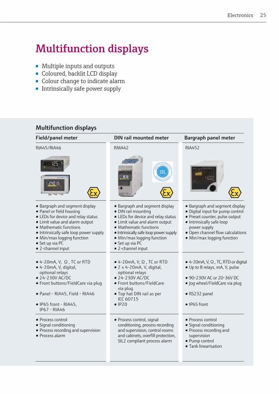
• Multipleinputsandoutputs• Coloured,backlitLCDdisplay• Colourchangetoindicatealarm• Intrinsicallysafepowersupply
Electronics
• Bargraph and segment display• Panel or field housing• LEDs for device and relay status• Limit value and alarm output• Mathematic functions • Intrinsically safe loop power supply • Min/max logging function• Set up via PC• 2-channel input
• Bargraph and segment display• DIN rail mounting• LEDs for device and relay status• Limit value and alarm output• Mathematic functions • Intrinsically safe loop power supply • Min/max logging function• Set up via PC• 2-channel input
• Bargraph and segment display• Digital input for pump control• Preset counter, pulse output• Intrinsically safe loop
power supply• Open channel flow calculations• Min/max logging function
Field/panel meter DIN rail mounted meter Bargraph panel meter
Multifunction displays
RIA45/RIA46 RMA42 RIA452
• Process control• Signal conditioning• Process recording and supervision• Process alarm
• Process control, signal conditioning, process recording and supervision, control rooms and cabinets, overfill protection, SIL2 compliant process alarm
• Process control• Signal conditioning• Process recording and
supervision• Pump control• Tank linearisation
• 4-20mA, V, Ω , TC or RTD• 4-20mA, V, digital,
optional relays• 24-230V AC/DC• Front buttons/FieldCare via plug
• Panel - RIA45, Field - RIA46
• IP65 front - RIA45, IP67 - RIA46
• 4-20mA, V, Ω , TC or RTD• 2 x 4-20mA, V, digital,
optional relays• 24-230V AC/DC• Front buttons/FieldCare
via plug• Top hat DIN rail as per
IEC 60715• IP20
• 4-20mA, V, Ω , TC, RTD or digital• Up to 8 relays, mA, V, pulse
• 90-230V AC or 20-36V DC• Jog wheel/FieldCare via plug
• RS232 panel
• IP65 front
Multifunction displays

26 Temperature products, recorders and system components
Measuring point positioning in a process reactor (top view)
Detailed engineering design including material selection, drawing and planning, along with fault-free installation are key factors in the quality and longevity of the measuring system. We tailor our project solutions to meet your needs, offering complete project management.
Flexible multipoint thermometersThesethermometersofferthepossibilityofdistributingmeasurementpointsthree-dimensionally within a reactor or vessel. Thermocouples enter the vessel via a common process connection and are routed to achieve the desiredpositionsofthemeasurementpoints.Thisflexibilityincreasesthenumber of measurements within a vessel from a single or limited number of processconnections,therebygivingabetterthermalprofileoftheprocess.
Connection box (EEx d version) with transmitters for multiple measurements.
Gas tight interchangeable thermocouples.

27
Variousdesignsareavailableincludingindividualinterchangeable measurement elements, where each measurement point is in contact with the thermowell wall for faster response to the process temperature. Terminals or transmitterscanbefittedintheconnectionboxthatiseitherfitteddirectlyontotheassemblyormountedremotely.
Multipoint thermometer with common sheathing Optimised multipoint (OMP) Constructed from a metallic sheath packed with high purified magnesium oxide powder with a number of conductors around a common central conductor. Thermocouple hot junctions are achieved by joining one of the negative outer conductors to the central positive conductor at different positions along the complete length of the sensor.
Stainless steel sheath
Hot junctionsThermocouple leg connectionsWall
Negative thermocouple legPositive thermocouple leg
Temperature engineering
Rigid multipoint thermometersRigid straight multipoint thermometers and thermowells are used for measuringtemperatureprofiles.Thesemultipointthermometersconsistof a thermowell with process connection, a number of sensors (usually thermocouples) and a connection box.
Version 1
Version 2
Multipoint element with individual sheaths Several mineral insulated thermocouples are placed into a metal tube, the generated multiple sensor is then drawn down in several steps to the required diameter.
28 Temperature products, recorders and system components
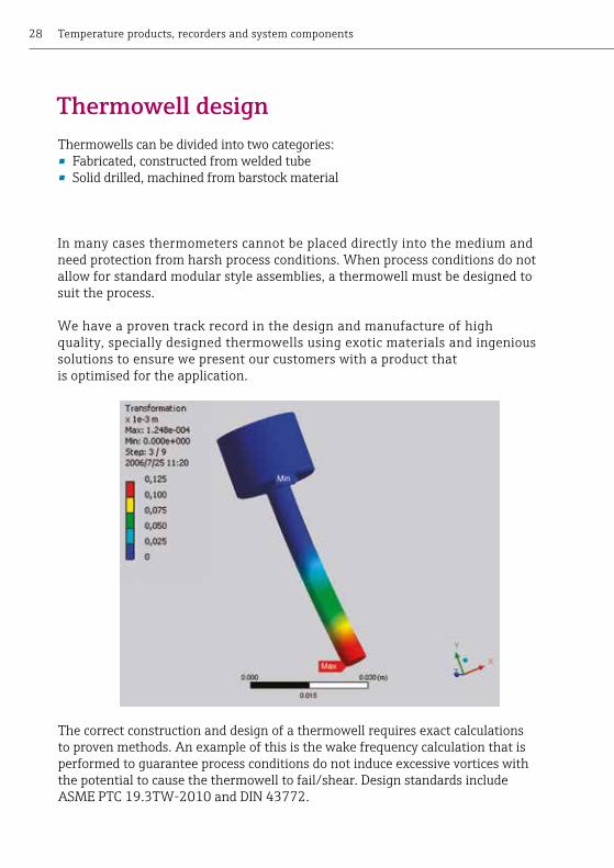
The correct construction and design of a thermowell requires exact calculations to proven methods. An example of this is the wake frequency calculation that is performed to guarantee process conditions do not induce excessive vortices with the potential to cause the thermowell to fail/shear. Design standards include ASME PTC 19.3TW-2010 and DIN 43772.
In many cases thermometers cannot be placed directly into the medium and need protection from harsh process conditions. When process conditions do not allow for standard modular style assemblies, a thermowell must be designed to suit the process.
We have a proven track record in the design and manufacture of high quality, specially designed thermowells using exotic materials and ingenious solutions to ensure we present our customers with a product that is optimised for the application.
Thermowell designThermowells can be divided into two categories: • Fabricated,constructedfromweldedtube• Soliddrilled,machinedfrombarstockmaterial

29
In RTD resistance sensors the electrical resistance changes with a change in temperature. They can measure temperatures typically between -200 and 600°C. They stand out due to their long term stability and high measurement accuracies. The most frequently used resistance sensor element is a Pt100.
There are two main RTD typesWire wound ceramic sensors:• Temperaturesupto600°C• Goodlongtermstability
Thinfilmsensors:• Temperaturesupto500°C
(QuickSens up to 200°C)• Smallerthanwirewound• Bettervibrationresistance
(StongSens up to 60g)
A thermocouple is a component made of twodifferentmetalsconnectedtoeachother at one end. An electrical potential (EMF)iscausedduetotheSeebeckEffectat the open end if the connection and thefreeendsareexposedtodifferenttemperatures. Thermocouples are suitable for temperature measurement in the range of 0°C to 1800°C. They stand out due to the fast response time and high vibration resistance.
There are three hot junction types.• Ungrounded:slowerresponsetime,
however the junction is isolated from the loop.
• Grounded:fasterresponsetimes-however at lower temperatures they can be exposed to ground loop interference.
• Exposed:fastestresponsetimes-cannotbeusedinflowing,pressurisedor corrosive applications and also are exposed to ground loop interference.
Technical reference
Insert technologiesTemperature is the most frequently measured parameter in the process industry. In electrical contact thermometers two measurement principles have asserted themselves as standard: RTDs and thermocouples.
RTDs Thermocouples

30 Temperature products, recorders and system components
Thread: The most commonly used thread types are NPT, G and M threads:• TheNPTthreadisaUSthreadnormfor
self-sealing pipe threads. • Gthreadsarecylindricalpipethreadsandseal
using the sealing area above the thread.• Mthreadsaremetricthreadswhichareused
at low process pressures.
Welded joint: The thermowell is directly welded into the vessel or pipe wall.
Compression fitting: The thermometer is put into a compression fittingandthenclampedusingeitherapipe(reusable)orsteelolive.Thecompressionfittingcan be screwed or welded into the process.
Flange: Flanges are subject to the DIN, ANSI/ASME orENstandards.Theyareclassifiedaccordingtomaterial, diameter and pressure rating.
Process connections (thermowell)The process connection is the connection between the process and the thermometer. The following are most commonly used in the process industries.
31
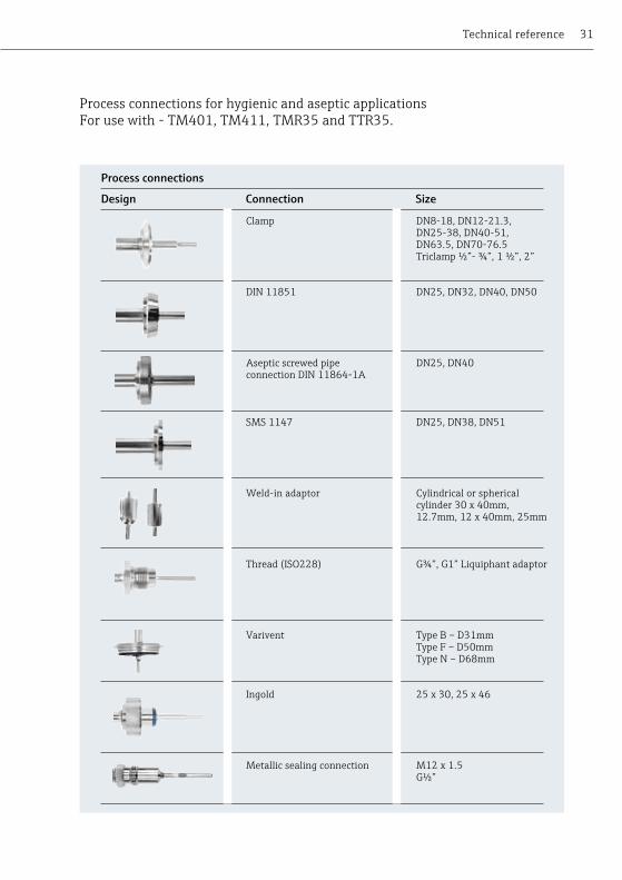
Process connections for hygienic and aseptic applicationsFor use with - TM401, TM411, TMR35 and TTR35.
Clamp DN8-18, DN12-21.3, DN25-38, DN40-51, DN63.5, DN70-76.5 Triclamp ½”- ¾”, 1 ½”, 2”
DIN 11851 DN25, DN32, DN40, DN50
Aseptic screwed pipe DN25, DN40 connection DIN 11864-1A
SMS 1147 DN25, DN38, DN51
Weld-in adaptor Cylindrical or spherical cylinder 30 x 40mm, 12.7mm, 12 x 40mm, 25mm
Thread(ISO228) G¾”,G1”Liquiphantadaptor
Varivent TypeB–D31mm TypeF–D50mm TypeN–D68mm
Ingold 25 x 30, 25 x 46
Metallic sealing connection M12 x 1.5 G½”
Technical reference
Process connections
Design Connection Size
32 Temperature products, recorders and system components
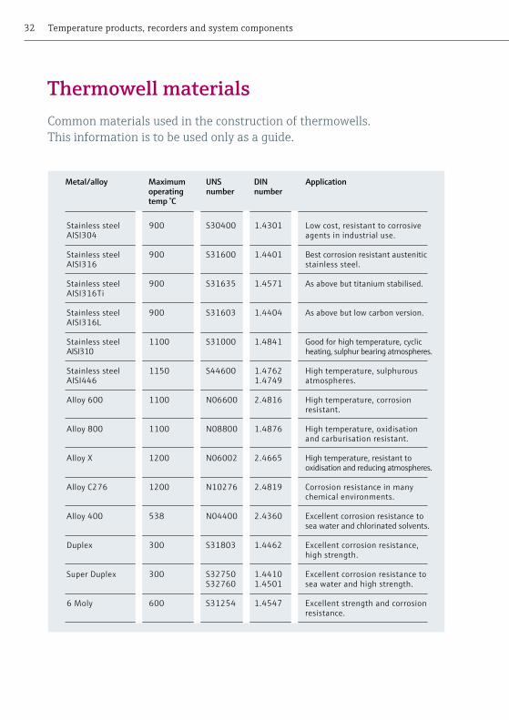
Stainless steel 900 S30400 1.4301 Low cost, resistant to corrosive AISI304 agents in industrial use.
Stainless steel 900 S31600 1.4401 Best corrosion resistant austenitic AISI316 stainless steel.
Stainless steel 900 S31635 1.4571 As above but titanium stabilised. AISI316Ti
Stainless steel 900 S31603 1.4404 As above but low carbon version. AISI316L
Stainless steel 1100 S31000 1.4841 Good for high temperature, cyclic AISI310 heating, sulphur bearing atmospheres.
Stainless steel 1150 S44600 1.4762 High temperature, sulphurous AISI446 1.4749 atmospheres.
Alloy 600 1100 N06600 2.4816 High temperature, corrosion resistant.
Alloy 800 1100 N08800 1.4876 High temperature, oxidisation and carburisation resistant.
Alloy X 1200 N06002 2.4665 High temperature, resistant to oxidisation and reducing atmospheres. Alloy C276 1200 N10276 2.4819 Corrosion resistance in many chemical environments.
Alloy 400 538 N04400 2.4360 Excellent corrosion resistance to sea water and chlorinated solvents.
Duplex 300 S31803 1.4462 Excellent corrosion resistance, high strength.
Super Duplex 300 S32750 1.4410 Excellent corrosion resistance to S32760 1.4501 sea water and high strength.
6 Moly 600 S31254 1.4547 Excellent strength and corrosion resistance.
Thermowell materialsCommon materials used in the construction of thermowells. This information is to be used only as a guide.
Metal/alloy Maximum operatingtemp °C
UNS number
DINnumber
Application

33
Kanthal AF 1300 FeCrAl High resistance to sulphurous, carburising and oxidising environments.
Special nickel/ 1200 NiCo Very good resistance to sulfidation and chloride.cobalt alloy Excellent resistance to oxidation, hot corrosion,
carburisation, metal dusting and nitridation.
C530 1400 Ceramic Very resistant to temperature shocks.
C610 1500 Ceramic Highly resistant to hydrogen fluoride, temperature shocks and mechanical influences.
C799 1800 Ceramic Resistance to hydrogen fluoride gases and alkaline vapours, oxidisation, reducing, neutral atmospheres and temperature shocks.
Sintered silicon 1650 Ceramic High thermal shock resistance, good thermalcarbide SiC conductivity. Furnaces, glass & ceramic industries.
Kanthal Super 1700 MoSi2 High thermal shock resistance and low porosity, with a extremely hard. glass phase
Special silicon 1400 Ceramic Excellent wear and thermal shock resistance.nitride ceramic SiN Cement industry and abrasive conditions.
Thermowell materials high temp TAF11, TAF12x & TAF16ThermowellscanbemanufacturedfromAISI316L,AISI310,AISI304,AISI446, Alloy 600 and Alloy 800. Please only use this as a guide and refer to the operating and technical instructions for a more in depth evaluation.
Technical reference
Material name Maximum operatingtemp °C
Short form
Application

34 Temperature products, recorders and system components
Connection modes2-wire: Electrical connection of the Pt100 resistanceFeatures: Additional measurement error due to temperature dependent resistance changes in the cabling.
Red
Whi
te
Red
Red
Whi
te
Red
Whi
te
Red
Whi
te
4-wire: Electrical connection of the Pt100 resistanceFeatures: Highly accurate. No additional measurement error due to temperature dependent resistance changes in the cabling.
3-wire: Electrical connection of the Pt100 resistanceFeatures: Accurate measurement. In the main avoids additional measurement error due to temperature dependent resistance changes in the cabling.
Wire wound element Thin film element
AA -50 to +250 0 to +150 ± ( 0.1 + 0.0017 [t] ) A -100 to +450 -30 to +300 ± ( 0.15 + 0.002 [t] )
B -196 to +600 -50 to +500 ± ( 0.3 + 0.005 [t] )
C -196 to +600 -50 to +600 ± ( 0.6 + 0.01 [t] )
Temp°C
Approximate tolerance bands of resistance and temperature
Resistance for Pt100 (Ω)
Class C Class B Class A Class AA 1/5 DIN 1/10 DIN± °C ± °C ± °C ± °C ± °C ± °C
-200.00 18.52 2.60 1.30 0.55 0.44 0.26 0.13-150.00 39.72 2.10 1.05 0.45 0.36 0.21 0.11-100.00 60.26 1.60 0.80 0.35 0.27 0.16 0.08-50.00 80.31 1.10 0.55 0.25 0.19 0.11 0.060.00 100.00 0.60 0.30 0.15 0.10 0.06 0.0350.00 119.40 1.10 0.55 0.25 0.19 0.11 0.06100.00 138.51 1.60 0.80 0.35 0.27 0.16 0.08150.00 157.33 2.10 1.05 0.45 0.36 0.21 0.11200.00 175.86 2.60 1.30 0.55 0.44 0.26 0.13250.00 194.10 3.10 1.55 0.65 0.53 0.31 -300.00 212.05 3.60 1.80 0.75 0.61 0.36 -350.00 229.72 4.10 2.05 0.85 0.70 - -400.00 247.09 4.60 2.30 0.95 - - -450.00 264.18 5.10 2.55 1.05 - - -500.00 280.98 5.60 2.80 - - - -550.00 297.49 6.10 3.05 - - - -600.00 313.71 6.60 3.30 - - - -650.00 329.64 7.10 3.55 - - - -
Tolerance classes for RTD thermometers as per IEC 60751 edition 2.0
Tolerance class Temperature range of validity (°C) Tolerance values (°C)

35
T/C Type
IEC code
Conductor
+ -
Temp. range ºC
Class 2Class 1
French toNFC 42-324
German toDIN 43714
Japanese to JIS C 1610-1981
American toANSI MC 96.1
K
J
K/N
T
E
R/S
B
J
T
N
E
B
R
S
Ni-Cr
Temp rangeTolerance valueTemp rangeTolerance value
Temp rangeTolerance valueTemp rangeTolerance value
Temp rangeTolerance valueTemp rangeTolerance value
Temp rangeTolerance valueTemp rangeTolerance value
Temp rangeTolerance valueTemp rangeTolerance value
Temp rangeTolerance valueTemp rangeTolerance value
Fe
Cu
Ni-Cr-SiNicrosil
Ni-Cr
Pt-30Rh
Pt-13Rh
Pt-10Rh
Ni-Al
-40 to 375°C±1.5°C375 to 750°C±0.4% reading
-40 to 375°C±1.5°C375 to 1000°C±0.4%
-40 to 125°C±0.5°C125 to 350°C±0.4% reading
-40 to 375°C±1.5°C375 to 800°C±0.4% reading
0 to 1100°C±1°C1100 to 1600°C±[1 +0.3% x (Rdg-1100)]°C
Notestablished
-40 to 333°C±2.5°C333 to 750°C±0.75% reading
-40 to 333°C±2.5°C333 to 1200°C±0.75% reading
-40 to 133°C±1°C133 to 350°C±0.75% reading
-40 to 333°C±2.5°C333 to 900°C±0.75% reading
0 to 600°C±1.5°C600 to 1600°C±0.25% reading
600 to 1700°C±0.25% reading
Cu-Ni Constantan
Pt-6Rh
Pt
Pt
-200 to +1200-40 to +750
-200 to +350
-200 to +900
600 to +17000 to +1600
0 to +1600
Cu-Ni Constantan
Ni-Si-Mg Nisil
Cu-Ni Constantan
-200 to +1200
Temperature range as defined in EN 60584 tolerance classes.
Technical reference
International colour codes for thermocouple cable insulation
IEC tolerance class EN 60584-2
InternationalEN 60584
Former BritishBS 4937

36 Temperature products, recorders and system components
The terminal heads, in which the terminal block or transmitter is installed, differinshapeandmaterialdependingontheapplication.Materialsusedareplastic, varnished aluminium or 316 stainless steel. All terminal heads have an internal form according to DIN 43729 (form B) as well as a thermometer connection of M24. The cable glands supplied with the terminal heads are suitable for cables with a diameter of 5-9mm.
Form B Standard (also with display) (Also with display)
Terminal heads
Process connectionsTA30A
TA30P
TA30HDouble cable entry
TA20B
IP
IP
IP
IP
IP
IP
IP
IP
IP
IP
IP
IP
TA30ADouble cable entry
TA30S
TA30D
TA30R
TA30H
TA21H
TA21E
TA30R(also with display)
66/67
65
66/67
65
66
69K
65
69K
66/67
66
66/67
66/68
Form BUZH
37
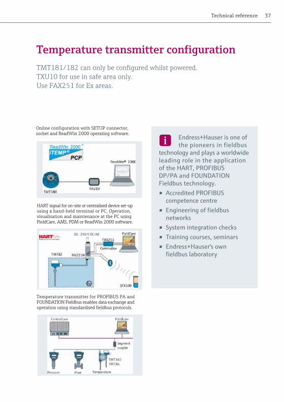
Endress+Hauser is one of the pioneers in fieldbus
technology and plays a worldwide leading role in the application of the HART, PROFIBUS DP/PA and FOUNDATION Fieldbus technology.• Accredited PROFIBUS
competence centre• Engineering of fieldbus
networks• System integration checks• Training courses, seminars• Endress+Hauser's own
fieldbus laboratory
Anwendung in Magazinen
Anwendung inBroschüren
Anwendung insw-Publikationen
Technical reference
Temperature transmitter configurationTMT181/182canonlybeconfiguredwhilstpowered.TXU10 for use in safe area only. Use FAX251 for Ex areas.
66/67
66/68
Temperature transmitter for PROFIBUS PA and FOUNDATION Fieldbus enables data exchange and operationusingstandardisedfieldbusprotocols.
Online configuration with SETUP connector, socketandReadWin2000operatingsoftware.
HART signal for on-site or centralised device set-up using a hand-held terminal or PC. Operation, visualisation and maintenance at the PC using FieldCare,AMS,PDMorReadWin2000software.

38 Temperature products, recorders and system components
Pipe schedule – inside diameter (all dimensions in mm)
½ 15 21.34 18.04 17.12 15.80 15.80 15.80 13.88 13.88 13.88 11.78 6.40
¾ 20 26.67 23.37 22.45 20.93 20.93 20.93 18.85 18.85 18.85 15.55 11.03
1 25 33.40 30.10 27.86 26.64 26.64 26.64 24.30 24.30 24.30 20.70 15.22
1 ½ 40 48.26 44.96 42.72 40.90 40.90 40.90 38.10 38.10 38.10 33.98 27.96
2 50 60.32 57.02 54.76 52.50 52.50 52.50 49.24 49.24 49.24 42.84 38.18
3 80 88.90 84.68 82.80 77.92 77.92 77.92 73.66 73.66 73.66 66.64 58.42
4 100 114.30 110.08 108.20 102.26 102.26 102.26 97.18 97.18 97.18 92.06 87.32 80.06
5 125 141.30 135.76 134.50 128.20 128.20 128.20 122.24 122.24 122.24 115.90 109.54 103.20
6 150 168.27 162.73 161.47 154.05 154.05 154.05 146.33 146.33 146.33 139.73 131.75 124.37
8 200 219.07 213.53 211.55 206.37 204.99 202.71 202.71 202.71 198.45 193.67 193.67 193.67 188.89 182.55 177.83 173.05 174.61
10 250 273.05 266.25 264.67 260.35 257.45 254.51 254.51 254.51 247.65 247.65 247.65 242.87 236.53 230.17 222.25 215.89 222.25
12 300 323.85 315.93 314.71 311.15 307.09 304.79 304.79 303.23 295.31 298.45 298.45 288.89 280.97 273.05 266.69 257.21 273.05
14 350 355.60 347.68 346.04 342.90 339.76 336.54 336.54 333.34 325.42 330.20 317.50 307.94 300.02 292.10 284.18
16 400 406.40 398.02 398.02 393.70 390.56 387.34 387.34 381.00 373.08 381.00 363.52 354.02 344.48 333.34 325.42
18 450 457.20 448.82 447.64 444.50 441.36 434.94 438.14 428.66 419.10 431.80 409.54 398.48 387.34 377.86 366.72
20 500 508.00 498.44 496.92 495.30 488.94 482.60 488.94 477.82 466.76 482.60 455.62 442.92 431.80 419.10 407.98
22 550 558.00 548.44 546.92 545.30 538.94 532.60 538.94 513.54 532.60 510.84 488.14 475.44 462.74 450.04
24 600 609.60 598.52 596.90 596.90 590.54 581.06 590.54 574.64 560.38 584.20 547.68 531.82 517.56 504.86 490.52
26 650 660.40 644.56 635.00 641.34 635.00
28 700 711.20 695.36 685.80 679.44 692.14 685.80
30 750 762.00 749.30 746.16 746.16 736.60 730.24 742.94 736.60
32 800 812.80 796.96 787.40 781.04 793.74 777.84 787.40
34 850 863.60 847.76 838.20 831.84 844.54 828.64 838.20
36 900 914.40 898.56 889.00 882.64 895.34 876.30 889.00
Inches mm 5S 10S 10 20 30 40S Std Wt 40 60 80S XS 80 100 120 140 160 XXS
Outside diameter
Pipe dimensions in accordance with ANSI B36.10
Nominal bore

39
Pipe schedule – inside diameter (all dimensions in mm)
½ 15 21.34 18.04 17.12 15.80 15.80 15.80 13.88 13.88 13.88 11.78 6.40
¾ 20 26.67 23.37 22.45 20.93 20.93 20.93 18.85 18.85 18.85 15.55 11.03
1 25 33.40 30.10 27.86 26.64 26.64 26.64 24.30 24.30 24.30 20.70 15.22
1 ½ 40 48.26 44.96 42.72 40.90 40.90 40.90 38.10 38.10 38.10 33.98 27.96
2 50 60.32 57.02 54.76 52.50 52.50 52.50 49.24 49.24 49.24 42.84 38.18
3 80 88.90 84.68 82.80 77.92 77.92 77.92 73.66 73.66 73.66 66.64 58.42
4 100 114.30 110.08 108.20 102.26 102.26 102.26 97.18 97.18 97.18 92.06 87.32 80.06
5 125 141.30 135.76 134.50 128.20 128.20 128.20 122.24 122.24 122.24 115.90 109.54 103.20
6 150 168.27 162.73 161.47 154.05 154.05 154.05 146.33 146.33 146.33 139.73 131.75 124.37
8 200 219.07 213.53 211.55 206.37 204.99 202.71 202.71 202.71 198.45 193.67 193.67 193.67 188.89 182.55 177.83 173.05 174.61
10 250 273.05 266.25 264.67 260.35 257.45 254.51 254.51 254.51 247.65 247.65 247.65 242.87 236.53 230.17 222.25 215.89 222.25
12 300 323.85 315.93 314.71 311.15 307.09 304.79 304.79 303.23 295.31 298.45 298.45 288.89 280.97 273.05 266.69 257.21 273.05
14 350 355.60 347.68 346.04 342.90 339.76 336.54 336.54 333.34 325.42 330.20 317.50 307.94 300.02 292.10 284.18
16 400 406.40 398.02 398.02 393.70 390.56 387.34 387.34 381.00 373.08 381.00 363.52 354.02 344.48 333.34 325.42
18 450 457.20 448.82 447.64 444.50 441.36 434.94 438.14 428.66 419.10 431.80 409.54 398.48 387.34 377.86 366.72
20 500 508.00 498.44 496.92 495.30 488.94 482.60 488.94 477.82 466.76 482.60 455.62 442.92 431.80 419.10 407.98
22 550 558.00 548.44 546.92 545.30 538.94 532.60 538.94 513.54 532.60 510.84 488.14 475.44 462.74 450.04
24 600 609.60 598.52 596.90 596.90 590.54 581.06 590.54 574.64 560.38 584.20 547.68 531.82 517.56 504.86 490.52
26 650 660.40 644.56 635.00 641.34 635.00
28 700 711.20 695.36 685.80 679.44 692.14 685.80
30 750 762.00 749.30 746.16 746.16 736.60 730.24 742.94 736.60
32 800 812.80 796.96 787.40 781.04 793.74 777.84 787.40
34 850 863.60 847.76 838.20 831.84 844.54 828.64 838.20
36 900 914.40 898.56 889.00 882.64 895.34 876.30 889.00
Inches mm 5S 10S 10 20 30 40S Std Wt 40 60 80S XS 80 100 120 140 160 XXS
Pipe schedule – inside diameter (all dimensions in mm)
Technical reference

40 Temperature products, recorders and system components
Bar Millibar Pa Kpa PSI in H20 mm H20 in Hg
1 1000 100,000 100 14.50 401.46 10197.16 29.53
0.001 1 100 0.1 0.0145 0.402 10.197 0.0295
0.00001 0.01 1 0.001 0.000145 0.00402 0.102 0.000295
0.01 10 1000 1 0.145 4.015 101.971 0.295
0.0689 68.948 6894.757 6.895 1 27.68 703.07 2.036
0.00249 2.491 249.0889 0.249 0.0361 1 25.4 0.0736
0.000098 0.0981 9.807 0.0098 0.00142 0.0393 1 0.0029
0.0339 33.863 3386.389 3.386 0.491 13.595 345.316 1
Commonly used units of pressure
Thread dimensions
Conversion factors
1 in = 25.4 mm 1 in3 = 16.39 cm3
1 ft = 0.3048 m 1 ft3 = 0.02832 m3
1 yd = 0.914 m 1 gal (imp) = 4546.09 cm3 1 mile = 1.609 km 1 litre = 1000 cm3
k kilo 103 1,000 h hecto 102 100 da deca 10 10 d deci 10-1 0.1 c centi 10-2 0.01 m milli 10-3 0.001 µ micro 10-6 0.000001
1 lb = 0.4536 kg 1 lb/in3 = 27.68 g/cm3
1 ton = 1016 kg 1 lb/ft3 = 16.018 kg/m3
1 tonne = 1000 kg 1 ft3/s = 0.02831 m3/s
Size Major Dia. Pitch (G = BSP) (mm) (mm)
G 1/8" 9.7 0.91
G 1/4" 13.2 1.34
G 3/8" 16.7 1.34
G 1/2" 21.0 1.81
G 5/8" 22.9 1.81
G 3/4" 26.4 1.81
G 1" 33.2 2.31
1/8" NPT 10.3 0.94
1/4" NPT 13.7 1.41
3/8" NPT 17.1 1.41
1/2" NPT 21.3 1.81
3/4" NPT 26.7 1.81
1" NPT 33.4 2.21
Length Volume
Abbreviation Prefix Factor Value
Mass Density & Flow
°C = °F -32 x 5/9 °F = °C x 9/5 + 32
Temperature conversion
41
60˚
50mm
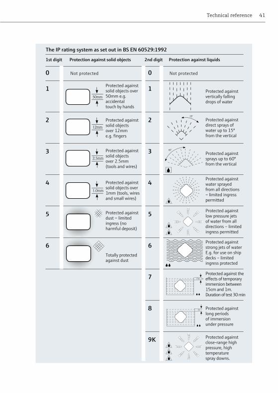
Protected against solid objects over50mm e.g. accidental touch by hands
12mm
Protected against solid objects over 12mm e.g. fingers
2.5mm
Protected against solid objects over 2.5mm (tools and wires)
1.0mm
Protected against solid objects over1mm (tools, wires and small wires)
Protected against dust – limited ingress (no harmful deposit)
Totally protected against dust
Protected against vertically fallingdrops of water
Protected against direct sprays ofwater up to 15º from the vertical
Protected against sprays up to 60ºfrom the vertical
Protected against water sprayed from all directions – limited ingress permitted
Protected against low pressure jets of water from all directions – limitedingress permitted
Protected against strong jets of waterE.g. for use on ship decks – limitedingress protected
Protected against the effects of temporary immersion between 15cm and 1m. Duration of test 30 min
Protected against long periods of immersion under pressure
Protected against close-range high pressure, high temperature spray downs.
15˚
.15m - 1m
1m +
Technical reference
The IP rating system as set out in BS EN 60529:1992
1st digit 2nd digitProtection against solid objects Protection against liquids
0
1
2
3
4
5
6
0
1
2
3
4
5
6
7
8
9K
Not protected Not protected

42 Temperature products, recorders and system components
Classification of divisions and zones
Apparatus groups (ATEX and IECEx)
Equipment groups (ATEX and IECEx)
Continuous hazard
I
IIA
IIB
IIC
IIIA
IIIB
IIIC
II (all other areas)
II (all other areas)
II (all other areas)
Intermittent hazard
Hazard under abnormal conditions
On occasion the ATEX and IEC zones may be used in the corresponding NEC and CEC system
Zone 0 / Zone 20 Cat 1
Gases, vapours
Combustible dusts
1
2
3
Zone 1 / Zone 21 Cat 2
Zone 2 / Zone 22 Cat 3
A place in which an explosive atmosphere is continuously present
Coal mining
Surface and other locations
Surface and other locations
Methane (Fire damp)
Acetic acid, Acetone, Ammonia, Butane, Cyclohexane, Gasoline (petrol), Kerosene, Methane (natural gas) (non-mining), Methanol (methyl alcohol), Propane, Propan-2-oI (iso-propyl alcohol), Toluene, Xylene
Di-ethyl ether, Ethylene, Methyl ethyl ketone (MEK), Propan-1-oI (n-propyl alcohol), Ethanol (ethyl alcohol)
Acetylene, Hydrogen, Carbon disulphide
Combustible flyings
Non-conductive
Conductive
Ga / Da
Gb / Db
Gc / Dc
Gas, vapour, mist, dust
Gas, vapour, mist, dust
Gas, vapour, mist, dust
Very High
High
Low
Two faults
One fault
Normal operation
A place in which an explosive atmosphere is likely to occur in normal operation
A place in which an explosive atmosphere is not likely to occur in normal operation but may occur for short periods
ATEX & IECEx certificate number
SIRA 13 ATEX 1234
Type of area
Group
Equipment group
ATEX and IEC
Environment
Equipment category
Definitions
Location Typical substance
Equipment protection level
Atmosphere Protection level
Required protection performance & operation
Name of notified body performing EC-type examination
Year of certification
Reference toATEX 95 directive
Serial number
IECEx
CSA 13.1234Reference to
IECEx scheme
Name of body performing IECEx certification
Year of certification
Serial number
Suffixes: U - component certification X - special conditions for safe use apply

43Technical reference
Typical ATEX & IECEx marketing (*ATEX only)
II 2 G Ex*Complies with
european directives*Notified body number
*Specific marking for explosion protection
*Equipmentgroup
*Equipmentcategory
*Environment Explosion protection
Protection Concepts (ATEX and IECEx)
General requirements
General requirements
Quartz / SandFilled
Type 'n' (sealing & hermetic sealing)Type 'n' (restricted breathing)
Increased safety
Flameproof
Type 'n' (enclosed break)
Oil immersion
Type 'n' (non-sparking)
Optical radiation
Enclosure
Intrinsic safety
Encapsulation
Pressurised
Intrinsic safety
Pressurised
Encapsulation
-
-
q
nC
nR
e
d
nC
o
nA
Op pr
ta
ia
ma
ia
px
ma
Op sh
tb
ib
mb
pD
ib
py
mb
Op is
tc
ic
mc
ic
pz
mc
-
-
Gb
Gc
Gc
Gb
Gb
Gc
Gb
Gc
Gb
Da
Da
Da
Db
Ga
Gb
Ga
Ga
Db
Db
Db
Dc
Gb
Gb
Gb
Ga
Dc
Dc
Dc
Gc
Gc
Gc
-
-
1,2
2
2
1,2
1,2
2
1,2
2
1,2
20
20
20
21,22
0,1,2
1,2
0,1,2
0,1,2
21
21
21
22
1,2
1,2
1,2
0,1,2
22
22
22
2
2
2
IEC 60079-0
IEC 60079-0
IEC 60079-5
IEC 60079-15
IEC 60079-7
IEC 60079-1
IEC 60079-15
IEC 60079-6
IEC 60079-15
IEC 60079-28
IEC 60079-31
IEC 60079-11
IEC 60079-18
IEC 61241-4
IEC 60079-11
IEC 60079-2
IEC 60079-18
-
-
Quench the flame
No arcs, sparks or hot surfaces
Contain the explosion, quench the flame
Enclosure IP54 or better
Protection against ignitions from optical radiation
Standard protection for dusts, rugged tight enclosure
Limit the energy of sparks and surface temperatures
Protection by encapsulation of incendive parts
Protection by pressurisation of enclosure
Limit the energy of sparks and surface temperatures
Keep the flammable gas out
Type of protectionElectrical equipment for gases, vapours and mists (G)
Electrical equipment for combustible dusts (D)
Symbol Typical IEC EPL
Typical zone(s)
IEC standard Basic concept of protection
0518
d IIC T4 Gb Ex tb IIIC DbT135oCType of
protectionGas
groupTemperature class (T1-T6)
Equipment Protection Level (EPL)
Explosion protection
Type of protection
Dust type
Equipment Protection Level (EPL)
Temperature class (oC)

UK
PU01
086T
/22/
EN/0
1.15
Endress+Hauser Ltd Floats Road Manchester M23 9NF Tel: 0161 286 5000 Fax: 0161 998 [email protected] www.uk.endress.com
Top Related