


Languages
Pages
Legal


T-SeriesPTFE Sealed Firesafe Valve

T Series FeaturesT-Series Features
For over 40 years Solent &Pratt has been at the forefrontof the design, development and manufacture of high qualitybutterfly valves for engineeringprojects around the world. An absolute commitment tooutstanding quality andreliability is the key of oursuccess, particularly inenvironments such as the oil and gas, chemical, petro-chemical and power generation industries.
Certification Certified Firesafe To BS 6755 Part 2
Operation Tight Shut Off In Both Directions To API 598.
Maintenance Field Replaceable PTFE Insert and Secondary Metal Seat.
Pressure Rating Ansi 150#, 300#. Pn 6, Pn 10, Pn 16, Pn 25.
Others On Request.
Geometry Double Offset Giving Low Unseating and Seating Torque.
Electro-Less Nickel Plated Spherical Disc Periphery.
Safety Feature Anti Blow Out Device To API 609
Body Designs Double Flanged
Wafer Lugged
Wafer Flangeless
Flange Designs ANSI
API
MSS
BS
PN
ISO
DIN
Actuation Manual Gearbox
Pneumatic
Electric
Hydraulic
Body Materials Standard; Carbon Steel (ASTM A216 WCB)
Stainless Steel (ASTM A351 CF8M)
Aluminium Bronze (BS1400 AB2)
Alternative Body Materials Monel 400
Zeron 100
Duplex Stainless Steels
Titanium
Avesta 254 6 Mo
Inconel
Hastelloy
Item Description Qty Material (Steel) Material (Stain.S) Material (Bronze)
1 Body 1 ASTM A216 WCB Stain.S 316 BS 1400 AB2
2 Disc 1 ASTM A216 WCB/ENP STAIN.S 316 BS 1400 AB2
3 Shaft 1 STAIN.S 17-4 PH STAIN.S 17-4PH MONEL K500
4 Retaining Ring 1 STAIN.S 316 STAIN.S 316 BS 1400 AB2
5 Secondary Metal Seat 1 INCONEL 625 INCONEL 625 INCONEL 625
6 PTFE Insert 1 PTFE PTFE PTFE
7 Thrust Ring 2 STAIN.S 316 STAIN.S 316 MONEL 400/
8 End Cover 1 STAIN.S 316 STAIN.S 316 BS 1400 AB2
9 Gland Plate 1 STAIN.S 316 STAIN.S 316 BS 1400 AB2
10 Gland Follower 1 STAIN.S 316 STAIN.S 316 BS 1400 AB2
11 Anti-Blow Out Ring 1 STAIN.S 316 STAIN.S 316 MONEL K500
12 Bearing 2 STAIN.S 304/PTFE STAIN.S 304/PTFE INCONEL/PTF
13 Shaft Pin 3 STAIN.S 17-4 PH STAIN.S 17-4 PH MONEL K500
14 Seat Gasket 1 GRAPHITE GRAPHITE GRAPHITE NS
15 Gland Packing 5 GRAPHITE GRAPHITE GRAPHITE
16 End Cover Gasket 1 GRAPHITE GRAPHITE GRAPHITE
17 Retaining Ring Screw 4-24 STAIN.S 304 STAIN.S 316 MONEL K500
18 End Cover Screw 4-6 STAIN.S 304 STAIN.S 304 STAIN.S 304
19 Gland Stud 2 STAIN.S 316 STAIN.S 316 STAIN.S 316
20 Gland Nut 2 STAIN.S 304 STAIN.S 304 STAIN.S 304
21 Key 1 STEEL STEEL STEEL
22 Rollpin 1 STAIN.S 304 STAIN.S 304 STAIN.S 304
Materials of Construction
1

Materials of Construction
2

The PTFE insert is rigidly held into thebody and ‘energised’ onto thespherically machined disc by means ofthe secondary seat which is fixed intothe body by a bolted in retaining ring.This version is used in low temperatureand ambient applications.
Geometry Features & Design
Operators
Valves can be supplied withmanual, electric, pneumatic or hydraulic actuators.Fail-safe systems for emergencyoperation are also available.
The PTFE insert is rigidly held in the bodyand ‘energised’ onto the sphericallymachined disc by means of the secondaryseat which extends onto the disc peripheryand fixed into the body by a bolted inretaining seat. When the PTFE insert is burntaway, during a fire, the secondary metal seatis designed to ‘energise’ onto the disc andform a seal in both directions.
General Design
The shaft is of 1 piece construction with an anti blow out feature external to the pressureboundary on the drive side conforming to API 609. If failure of the shaft to discconnection or internal failure of the shaft occurs due to excessive torques, no portion ofthe shaft can be ejected from the valve as result of internal pressure. This single piececonstruction also provides a rigid assembly when pinned to the disc via means of shaftpins (peened over and locked). This prevents excessive disc deflections, which maintainsa constant disc/insert contact stress ensuring a bi-directional sealing valve at both low andhigh pressures. The valve has a double offset design providing a camming action. Thiseliminates excessive wear between the seat and disc sealing interface both during theopening and closing strokes extending the sealing life of the valve. Maintenance of thevalve is quick and relatively simple. The PTFE insert, seat gasket and secondary seat canbe replaced by simply un-bolting the retaining ring and assembling the new parts withoutremoving any other parts. Gland packing is simply adjusted by tightening gland nuts,which are easily accessible between the mounting legs with having to remove the adaptorplate or actuator.
3
Standard Design Firesafe Design

3 80 48 29 125 167 50 20 44
4 100 54 31.5 161 197 50 28 61.6
6 150 57 36.5 168 215 55 35 77
8 200 64 41.5 202 248 70 60 132
10 250 71 47.5 235 285 70 80 176
12 300 81 50 285 328 78 120 264
14 350 92 58.5 315 362 77 150 335
16 400 102 62.5 360 390 90 190 418
18 450 114 72 386 424 105 215 473
20 500 127 75.5 402 450 100 275 605
24 600 154 88.5 489 546 137 445 979
26 650 229 114.5 485 560 150 560 1232
28 700 229 114.5 515 600 150 650 1430
30 750 229 114.5 597 635 160 785 1727
32 800 229 114.5 636 690 160 845 1859
34 850 241 120.5 610 710 180 1050 2310
36 900 241 120.5 635 735 180 1150 2530
38 950 300 150 670 770 180 1340 2948
40 1000 300 150 695 795 200 1500 3300
42 1050 300 150 725 825 225 1605 3531
44 1100 300 150 750 840 250 1795 3949
46 1150 350 175 780 890 275 1995 4389
48 1200 350 175 815 925 300 2200 4862
Technical Data
Valve size Dim. Dim. Dim. Dim. Dim. Wt. Wt.Inches mm A B C D E Kg. Lbs.
T-Series 150# range (dimensions in mm)
4
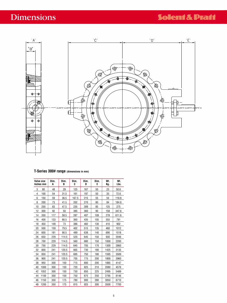
Dimensions
3 80 48 29 125 167 50 23 50.6
4 100 54 31.5 161 197 50 33 72.6
6 150 59 36.5 167.5 215 55 54 118.8
8 200 73 41.5 202 270 80 84 184.8
10 250 83 47.5 235 309 85 125 275
12 300 92 50 385 360 90 158 347.6
14 350 117 58.5 287 407 109 278 611.6
16 400 133 66.5 360 435 105 355 781
18 450 149 73 386 482 130 410 902
20 500 159 79.5 402 515 135 460 1012
24 600 181 90.5 489 638 140 690 1518
26 650 229 114.5 520 645 150 930 2046
28 700 229 114.5 560 680 150 1000 2200
30 750 229 114.5 645 705 170 1300 2860
32 800 241 120.5 665 730 180 1425 3135
34 850 241 120.5 695 750 180 1595 3509
36 900 241 120.5 705 775 200 1800 3960
38 950 300 150 715 800 200 1885 4147
40 1000 300 150 720 825 210 2080 4576
42 1052 300 150 730 850 225 2495 5489
44 1100 300 150 750 875 250 2795 6146
46 1150 350 175 780 900 280 3050 6710
48 1200 350 175 815 925 300 3500 7700
Valve size Dim. Dim. Dim. Dim. Dim. Wt. Wt.Inches mm A B C D E Kg. Lbs.
T-Series 300# range (dimensions in mm)
5

Topworks/Actuator Mountings
6
SIZE A B C D E F G H J K L MINCHES/MM
RANGE 150#3 80 48 29 120 30 50 15.984 79 - 16 4 M6 13
15.9474 100 54 31.5 120 30 50 19.980 79 - 16 4 M6 13
19.9476 150 57.5 36 120 28 55 24.980 95 - 16 4 M6 13
24.9478 200 64 41 130 28 70 21.480 95 - 16 4 M8 18
21.44710 250 71 47 152 22 70 25.980 95 - 16 4 M8 18
25.94712 300 81 50 152 36 78 31.975 127 - 25.4 4 M10 18
31.93614 350 92 58.5 178 35 77 34.975 127 - 25.4 4 M10 18
34.93616 400 102 62.5 238 49 90 39.975 178 - 41 4 M12 25
39.93618 450 114 72 240 51 105 44.975 197 - 51 4 M16 23
44.93620 500 127 75.5 284 67 100 51.970 197 - 63.5 4 M20 323
51.92424 600 154 88.5 282 50 137 61.970 241.3 - 76.2 4 M20 32
61.924
SIZE A B C D E F G H J K L MINCHES/MM
RANGE 300#3 80 48 29 120 30 50 15.984 79 - 16 4 M6 13
15.9474 100 54 31.5 120 30 50 19.980 79 - 16 4 M6 13
19.9476 150 60 36 127 31.5 55 24.980 90 - 16 4 M8 18
24.9478 200 73 41.5 150 35 80 31.975 127 - 25.4 4 M10 18
31.93610 250 86.7 47 212 46 85 37.975 178 - 41 4 M12 21
37.93612 300 95 50 208 34 90 44.975 178 - 41 4 M12 21
44.93614 350 177 58.5 277 65 109 54.970 197 - 63.5 4 M16 26
54.92416 400 133 66.5 238 44 105 59.970 197 - 63.5 4 M20 32
59.92418 450 149 73 288 54 130 69.970 241.3 - 76.2 4 M20 32
69.92420 500 159.5 80 344 74 135 74.970 285 305 110 6 M20 34
74.92424 600 181 90.5 352 75 140 89.964 285 305 110 6 M20 30
89.910

T Series/08/01
Other product ranges available from Solent & Pratt include:
• R-Series Resilient Seal Butterfly valves. Sizes: 2” (50mm) to 84” (2100mm)
• E-Series Ebonite Lined Butterfly valves. Sizes : 3” (80mm) to 84” (2100mm)
• T-Series High Performance Butterfly valves, Teflon - sealed firesafe. Sizes: 3” (80mm) to 48” (1200mm)
• TOSV Quarter Turn series. Sizes: 3” (800mm) to 84” (2100mm). Temperature range up to 1292˚F (700˚C)
• TOGV Gate Valve Series. Sizes: 3” (80mm) to 24” (600mm). Temperature range to up to 1292˚F (700˚C)
• TOSV Double Block and Bleed series. Sizes: 6” (150mm) to 84” (2100mm). Temperature range up to 932˚F (500˚C)
• TOSV Cryogenic series. Sizes: 3” (80mm) to 84” (2100mm). Temperature range down to -320˚F (-196˚C)
• Control Butterfly Valves. Actuated for both isolation and control duty.
While this information is presented in good faith and believed to be accurate, Solent & Pratt, A Division of Curtiss-Wright Flow Control (UK) Ltd., does notguarantee satisfactory results from reliance on such information. Nothing contained herein is to be construed as a warranty or guarantee, expressed or implied,regarding the performance, merchantability, fitness or any other matter with respect to the products, nor as a recommendation to use any product or processin conflict with patent. Solent & Pratt, A Division of Curtiss-Wright Flow Control (UK) Ltd., reserves the right, without notice, to alter or improve the designs orspecifications of the products described herein.
Solent & PrattA Division of Curtiss-Wright Flow Control (UK) Ltd.
Corporate Headquarters202 St. Andrews Road, Bridport, Dorset DT6 3BSPhone: +44 (0) 1308 422256Fax: +44 (0) 1308 427760E-mail: [email protected]: www.cwfc.com
U.S.Sales Office10195 Brecksville RoadBrecksville, OHIO44141, U.S.A.Phone: 440-838-7690Fax: 440-838-7699E-mail: [email protected]: www.cwfc.com
For a listing of worldwide offices and representatives, visit out website at www.cwfc.com
Top Related