


Languages
Pages
Legal


STANLEY, Engineered Fastening
Fastening Solutions for Plastics
Dodge®
Fastening Solutions for Plastics
Dodge®
Dodge' Inserts Dodge inserts for plastics are the most widely recognized and highly regarded
products in the fastening market. Since the 1950's, Dodge has been identified
as the leader in its industry which can largely be attributed to its focus on providing high quality products.
Plastic Parts, Metal Threads
Threaded Inserts Dodge inserts are designed to provide the high performance strength values of molded-in
inserts while retaining all of the economical advantages of insert installation after molding.
Compression Limiters Dodge non-threaded bushings expand the Dodge offering and are custom designed for your
specific application. The Limiters can be pressed in or installed with either heat or ultrasonics.
They are designed to minimize any cracking of plastic parts due to bolt load.
Engineering Dodge Sales Engineers have broad experience in insert technology and are available
to provide answers to any of your technical questions. Our highly trained Applications
Engineering staff in Danbury, Connecticut will be glad to furnish technical assistance, compile
test data, prepare samples for your evaluation and make specific recommendations on insert
designs, installations and assembly systems. Our fastening experience and expertise is available
for designing special inserts for unique or critical applications.
Quality Dodge products are manufactured to the same exacting quality systems required by the
military, aerospace and automotive standards. The Danbury manufacturing facility has been
certified ISO/TS 16949: 2009 and ISO 14001. We are committed to an ongoing and never
ending process of quality improvement and total customer satisfaction.
STANLEY. Engineered Fastening - 2 - www.StanleyEngineeredFastening.com - 2 - www.StanleyEngineeredFastening.com
InsertsDodge inserts for plastics are the most widely recognized and highly regarded products in the fastening market. Since the 1950’s, Dodge has been identified as the leader in its industry which can largely be attributed to its focus on providing high quality products.
Plastic Parts, Metal Threads
Threaded Inserts Dodge inserts are designed to provide the high performance strength values of molded-in
inserts while retaining all of the economical advantages of insert installation after molding.
Compression LimitersDodge non-threaded bushings expand the Dodge offering and are custom designed for your
specific application. The Limiters can be pressed in or installed with either heat or ultrasonics.
They are designed to minimize any cracking of plastic parts due to bolt load.
Engineering Dodge Sales Engineers have broad experience in insert technology and are available
to provide answers to any of your technical questions. Our highly trained Applications
Engineering staff in Danbury, Connecticut will be glad to furnish technical assistance, compile
test data, prepare samples for your evaluation and make specific recommendations on insert
designs, installations and assembly systems. Our fastening experience and expertise is available
for designing special inserts for unique or critical applications.
QualityDodge products are manufactured to the same exacting quality systems required by the
military, aerospace and automotive standards. The Danbury manufacturing facility has been
certified ISO/TS 16949: 2009 and ISO 14001. We are committed to an ongoing and never
ending process of quality improvement and total customer satisfaction.
Dodge® Table of Contents
Page
Introduction to Dodge Products 2
Design Guidelines 4-7
Applications 8-9
Dodge Capabilities 10
Testing Terminology 10
Troubleshooting Guide 11
Insert Selection Guide: Specifications & Test Data
Ultrasert® I 12-13
Ultrasert® II 14-15
Ultrasert® II Screw Lock 16-17
Ultrasert® III. 18-19
Ultrasert® IV. 20-21
Ultrasert® IV Flanged 22-23
Ultraseal® 24
Ultra-Molds 25
Miniature 26
Expansion, Standard 27
Expansion, Clinch 28
Expansion, Flanged 29
Self Threading 30
Self Threading, Flanged 31
Spred-Lok 32
Ta perTur 33
Compression Limiters 34
The test data included in this catalogue should be considered as average values for the general families of plastics indicated. Critical application requirements may necessitate further specific testing. As a result of continuous design improvement, Dodge products are subject to modification. Current technical data and drawings are available upon request.
STANLEY. Engineered Fastening - 3 - www.StanleyEngineeredFastening.com - 3 - www.StanleyEngineeredFastening.com
Table of Contents
The test data included in this catalogue should be considered as average values for the general families of plastics indicated. Critical application requirements may necessitate further specific testing.As a result of continuous design improvement, Dodge products are subject to modification.Current technical data and drawings are available upon request.
Page
Introduction to Dodge Products................................................................................................................ 2
Design Guidelines.................................................................................................................................... 4-7
Applications............................................................................................................................................ 8-9
Dodge Capabilities.................................................................................................................................. 10
Testing Terminology................................................................................................................................. 10
Troubleshooting Guide............................................................................................................................ 11
Insert Selection Guide: Specifications & Test Data
Ultrasert® I.......................................................................................................................................... 12-13
Ultrasert® II................................................................................................................................... ..... 14-15
Ultrasert® II Screw Lock....................................................................................................................... 16-17
Ultrasert® III........................................................................................................................................ 18-19
Ultrasert® IV........................................................................................................................................ 20-21
Ultrasert® IV Flanged........................................................................................................................... 22-23
Ultraseal®........................................................................................................................................... 24
Ultra-Mold®........................................................................................................................................ 25
Miniature............................................................................................................................................ 26
Expansion, Standard............................................................................................................................ 27
Expansion, Clinch................................................................................................................................ 28
Expansion, Flanged.............................................................................................................................. 29
Self Threading...................................................................................................................................... 30
Self Threading, Flanged........................................................................................................................ 31
Spred-Lok............................................................................................................................................ 32
TaperTuff®........................................................................................................................................... 33
Compression Limiters........................................................................................................................... 34
Dodge® Design Guidelines
1. Plastic Overview
The two main categories of plastics where threaded inserts are used:
a. Thermoset Plastics Thermoset plastics cannot be re-melted using heat or pressure once they are formed into their desired shape, These plastics tend to be hard and brittle. Since they will not re-melt, inserts installed by heat or ultrasonic can't be used in these materials. Recommended insert types include: » Self-Threading » Expansion » Press-In designs
Thermoset Types » Phenolic » Epoxies » Vulcanized rubber » Polyamide
b. Thermoplastics Thermoplastic materials can be re-melted and re-formed once formed into their desired shape.
Heat and Ultrasonically installed inserts perform best in thermoplastic types of materials however Self-Threading, Expansion and Press-in style inserts may also be utilized in these materials.
Thermoplastics Types » ABS » PVC » Polycarbonate » Nylon
Fills (Additives) Thermoplastic materials may be unfilled or may have a wide variety of fillers added to them to increase the stiffness or toughness properties of the material for specific applications. These fillers may include nylon or carbon fiber, mineral or even metal.
2. Insert Characteristics
Dodge Inserts for Plastics are designed to provide the strength necessary to allow bolts and screws to be tightened to the levels required to stretch the fastener and maintain a sufficient bolted joint assembly.
The insert must also provide resistance to rotation and pull-out under a wide variety of load and atmospheric conditions in a given assembly.
The optimum insert design depends on several factors including: » Plastic resin » Type and percentage of fill » Preferred insert installation method » Application strength requirements » Environmental concerns
3. Material And Plating
Material Dodge inserts are traditionally made from 360 brass which falls under the designation UNS C36000 1/2 hard free-cutting brass. The CDA specification is C360, 1/2 hard per ASTM B-16.
Dodge inserts are also available in alternate materials including Steel and Aluminum. Contact Applications Engineering for further information.
8 2 Ta .ered Hole
Plating Inserts and Compression Limiters may be processed with Sharp
a variety of finishes from nickel Knurls
plates and automotive finishes Firs
to colored dyes to distinguish insert types or installations. Please consult our Applications Engineering team for assistance with your requirements.
4. Insert Geometry
a. Undercuts To accommodate the best overall balance of rotational and pull-out strength of an insert, the knurl bands are combined with undercuts, fins or a combination of both.
b. Knurl Patterns The most common design methods used to increase rotational strength of an insert include increasing body diameter or increasing or changing the knurl pattern on a given insert design. The rotational resistance of an insert design can change dramatically by altering the coarseness or fineness of a knurl.
Coarser knurl patterns can provide a significant increase in rotational strength but can also induce significant stress into the insert/plastic assembly which could ultimately lead to cracking and premature failure.
Diamond
Helical Straight
» Diamond Knurls Generally the most effective when the insert design is large and the knurl is coarser.
Undercuts
» Helical Knurls While normally not as aggressive as a straight knurl, they are the more common solution. These knurls will provide adequate resistance to insert rotation.
STANLEY. Engineered Fastening - 4 - www.StanleyEngineeredFastening.com - 4 - www.StanleyEngineeredFastening.com
Design Guidelines
1. Plastic Overview
The two main categories of plastics where threaded inserts are used:
a. Thermoset PlasticsThermoset plastics cannot be re-melted using heat or pressure once they are formed into their desired shape, These plastics tend to be hard and brittle. Since they will not re-melt, inserts installed by heat or ultrasonic can’t be used in these materials. Recommended insert types include: » Self-Threading » Expansion » Press-In designs Thermoset Types» Phenolic » Epoxies » Vulcanized rubber » Polyamide
b. ThermoplasticsThermoplastic materials can be re-melted and re-formed once formed into their desired shape.
Heat and Ultrasonically installed inserts perform best in thermoplastic types of materials however Self-Threading, Expansion and Press-in style inserts may also be utilized in these materials.
Thermoplastics Types» ABS » PVC » Polycarbonate » Nylon
Fills (Additives)Thermoplastic materials may be unfilled or may have a wide variety of fillers added to them to increase the stiffness or toughness properties of the material for specific applications. These fillers may include nylon or carbon fiber, mineral or even metal.
2. Insert Characteristics
Dodge Inserts for Plastics are designed to provide the strength necessary to allow bolts and screws to be tightened to the levels required to stretch the fastener and maintain a sufficient bolted joint assembly.
The insert must also provide resistance to rotation and pull-out under a wide variety of load and atmospheric conditions in a given assembly.
The optimum insert design depends on several factors including:» Plastic resin» Type and percentage of fill» Preferred insert installation method» Application strength requirements» Environmental concerns
3. Material And Plating
MaterialDodge inserts are traditionally made from 360 brass which falls under the designation UNS C36000 ½ hard free-cutting brass. The CDA specification is C360, ½ hard per ASTM B-16.
Dodge inserts are also available in alternate materials including Steel and Aluminum. Contact Applications Engineering for further information.
PlatingInserts and Compression Limiters may be processed with a variety of finishes from nickel plates and automotive finishes to colored dyes to distinguish insert types or installations. Please consult our Applications Engineering team for assistance with your requirements.
4. Insert Geometry
a. Undercuts To accommodate the best overall balance of rotational and pull-out strength of an insert, the knurl bands are combined with undercuts, fins or a combination of both.
b. Knurl PatternsThe most common design methods used to increase rotational strength of an insert include increasing body diameter or increasing or changing the knurl pattern on a given insert design. The rotational resistance of an insert design can change dramatically by altering the coarseness or fineness of a knurl.
Coarser knurl patterns can provide a significant increase in rotational strength but can also induce significant stress into the insert/plastic assembly which could ultimately lead to cracking and premature failure.
Diamond Helical Straight
» Diamond Knurls Generally the most effective when the insert design is large and the knurl is coarser.
» Helical Knurls While normally not as aggressive as a straight knurl, they are the more common solution. These knurls will provide adequate resistance to insert rotation.
Incorrect
Dodge® Design Guidelines
» Straight Knurls Effective in applications focused on high rotational strength.
» Multiple Knurls It is common practice to utilize more than one knurl style and direction on the same part to reach the most optimum combination of rotational and torque resistance.
c. Tapers To eliminate installation issues, many inserts are designed to be installed into a tapered hole. This allows for the insert to "self-align" during installation and requires less heat energy as the mass of plastic resin that is required to melt is less than with other hole designs. A tapered insert must always be used in a tapered hole.
d. Flanges In certain applications, it is advantageous to have a large bearing surface to distribute the load applied when fastening mating parts. A large flange not only increases the bearing surface but also allows for adjustment of the mating part without a negative effect on insert strength.
Straight vs. Tapered Holes - Straight hole preparation allows for a taper that should not exceed a 1 degree included angle. Tapered holes require an 8 degree included angle. Tapering permits easy release of the core pin, aids in insert alignment, which in turn reduces installation time.
» Counterbores —Traditionally are not recommended as they may interfere with proper insert alignment. Self threading inserts, or flanged inserts which should be installed flush, are the exception to the rule.
» Recommended Hole Depth - Allows for proper insert set down (flush to 0.005 inch below the surface), prevents excessive flash, and prevents back filling of plastic from entering bottom threads.
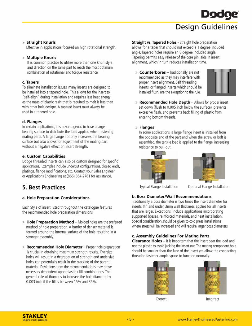
» Flanges In some applications, a large flange insert is installed from the opposite end of the part and when the screw or bolt is assembled, the tensile load is applied to the flange, increasing resistance to pull-out.
e. Custom Capabilities Dodge Threaded Inserts can also be custom designed for specific applications. Examples include undercut configurations, closed ends, platings, flange modifications, etc. Contact your Sales Engineer or Applications Engineering at (866) 364-2781 for assistance.
Ath
5. Best Practices
a. Hole Preparation Considerations
Each Style of insert listed throughout the catalogue features the recommended hole preparation dimensions.
Hole Preparation Method — Molded holes are the preferred method of hole preparation. A barrier of denser material is formed around the internal surface of the hole resulting in a stronger assembly.
Recommended Hole Diameter — Proper hole preparation is crucial in obtaining maximum strength results. Oversize holes will result in a degradation of strength and undersize holes can potentially result in the cracking of the parent material. Deviations from the recommendations may prove necessary dependent upon plastic / fill combinations. The general rule of thumb is to increase the hole diameter by 0.003 inch if the fill is between 15% and 35%.
Typical Flange Installation Optional Flange Installation
b. Boss Diameter/Wall Recommendations Traditionally a boss diameter is two times the insert diameter for inserts 1/4" and under, 3mm wall thickness applies for all inserts that are larger. Exceptions include applications incorporating supported bosses, reinforced materials, and heat installation. Special consideration should be given to cold press installations where stress will be increased and will require larger boss diameters.
c. Assembly Guidelines For Mating Parts Clearance Holes — It is important that the insert bear the load and not the plastic to avoid jacking the insert out. The mating component hole should be smaller than the face of the insert yet allow the connecting threaded fastener ample space to function normally.
ILA
N
)
Correct
STANLEY. Engineered Fastening - 5 - www.StanleyEngineeredFastening.com - 5 - www.StanleyEngineeredFastening.com
» Straight Knurls Effective in applications focused on high rotational strength.
» Multiple Knurls It is common practice to utilize more than one knurl style and direction on the same part to reach the most optimum combination of rotational and torque resistance.
c. Tapers To eliminate installation issues, many inserts are designed to be installed into a tapered hole. This allows for the insert to “self-align” during installation and requires less heat energy as the mass of plastic resin that is required to melt is less than with other hole designs. A tapered insert must always be used in a tapered hole.
d. FlangesIn certain applications, it is advantageous to have a large bearing surface to distribute the load applied when fastening mating parts. A large flange not only increases the bearing surface but also allows for adjustment of the mating part without a negative effect on insert strength.
e. Custom CapabilitiesDodge Threaded Inserts can also be custom designed for specific applications. Examples include undercut configurations, closed ends, platings, flange modifications, etc. Contact your Sales Engineer or Applications Engineering at (866) 364-2781 for assistance.
5. Best Practices
a. Hole Preparation Considerations
Each Style of insert listed throughout the catalogue features the recommended hole preparation dimensions.
» Hole Preparation Method – Molded holes are the preferred method of hole preparation. A barrier of denser material is formed around the internal surface of the hole resulting in a stronger assembly.
» Recommended Hole Diameter – Proper hole preparation is crucial in obtaining maximum strength results. Oversize holes will result in a degradation of strength and undersize holes can potentially result in the cracking of the parent material. Deviations from the recommendations may prove necessary dependent upon plastic / fill combinations. The general rule of thumb is to increase the hole diameter by 0.003 inch if the fill is between 15% and 35%.
Straight vs. Tapered Holes - Straight hole preparation allows for a taper that should not exceed a 1 degree included angle. Tapered holes require an 8 degree included angle. Tapering permits easy release of the core pin, aids in insert alignment, which in turn reduces installation time.
» Counterbores – Traditionally are not recommended as they may interfere with proper insert alignment. Self threading inserts, or flanged inserts which should be installed flush, are the exception to the rule.
» Recommended Hole Depth - Allows for proper insert set down (flush to 0.005 inch below the surface), prevents excessive flash, and prevents back filling of plastic from entering bottom threads.
» Flanges In some applications, a large flange insert is installed from the opposite end of the part and when the screw or bolt is assembled, the tensile load is applied to the flange, increasing resistance to pull-out.
Typical Flange Installation Optional Flange Installation b. Boss Diameter/Wall RecommendationsTraditionally a boss diameter is two times the insert diameter for inserts ¼” and under, 3mm wall thickness applies for all inserts that are larger. Exceptions include applications incorporating supported bosses, reinforced materials, and heat installation. Special consideration should be given to cold press installations where stress will be increased and will require larger boss diameters.
c. Assembly Guidelines For Mating PartsClearance Holes – It is important that the insert bear the load and not the plastic to avoid jacking the insert out. The mating component hole should be smaller than the face of the insert yet allow the connecting threaded fastener ample space to function normally.
Correct Incorrect
Design Guidelines

Dodge® Design Guidelines
d. Compression Limiters Considerations
Strength —The head of the bolt being used in the assembly must seat against the compression limiter to avoid potential failure due to plastic creep.
Mating Components —The mating component must also withstand the stress generated by the clamping force. In instances where the mating component will also be plastic, the use of a secondary insert should be considered.
Types of Applications
Structural » Insert is equal to or larger than the flange » Provides higher axial strength » Failure mode is the bolt
Non-Structural » Insert is smaller than the flange » Has simple OD configuration » Applies to smaller inserts under 1/2" OD
Gap Jr •
Structural
Non-Structural
Note: Gap allows for a gasket, (e.g., manifold applications)
6. Methods Of Installation
Dodge Inserts are designed for post mold and molded-in installations.
Post molding is cost effective in that it generally shortens cycle time of the molding process, reduces rejects and damage from inserts that could potentially come loose and damage the mold. Molded-In inserts offer higher torque and pull-out resistance.
Several Dodge insert designs are available for Post-Molding using Ultrasonic installation or Heat installation.
a. Heat Installation Heat installation involves positioning the insert into the molded or drilled hole. A heated tip is then inserted into the inside diameter of the threaded insert.
Localized melting begins to take place and with the downward pressure, the insert begins to install. Plastic flows into the varying undercuts and knurls.
Benefits of thermal installation include: » installation of multiple inserts at a given time » ability to install inserts beyond 1/4" » superior strength assemblies
b. Ultrasonic Installation Ultrasonic Installation involves positioning the insert into a molded or drilled hole.
An ultrasonic horn then contacts the insert and begins to vibrate the insert. This vibration creates frictional heat which melts the plastic allowing the horn to lower the insert into position. Once installed to the appropriate depth, the cycle is repeated for the next insert.
c. Self -Tapping/Self Threading, Spred-Lok, Expansion Inserts and Mold-In
Designed for ease of installation. Primarily involves preparing straight holes and driving the insert into place, pressing the insert into place, or pressing and then expanding the insert into place. Minimal tooling is required.
cl. Self Tapping Economical and easy to install. Provides excellent pull out resistance. Insert design features a cutting edge slot which assists in installation.
STANLEY. Engineered Fastening - www.StanleyEngineeredFastening.com - 6 - www.StanleyEngineeredFastening.com
d. Compression Limiters Considerations
Strength – The head of the bolt being used in the assembly must seat against the compression limiter to avoid potential failure due to plastic creep.
Mating Components – The mating component must also withstand the stress generated by the clamping force. In instances where the mating component will also be plastic, the use of a secondary insert should be considered.
Types of Applications
Structural » Insert is equal to or larger than the flange » Provides higher axial strength » Failure mode is the bolt
Non-Structural » Insert is smaller than the flange » Has simple OD configuration » Applies to smaller inserts under ½” OD
Structural Non-Structural
Note: Gap allows for a gasket, (e.g., manifold applications)
6. Methods Of Installation
Dodge Inserts are designed for post mold and molded-in installations.
Post molding is cost effective in that it generally shortens cycle time of the molding process, reduces rejects and damage from inserts that could potentially come loose and damage the mold. Molded-In inserts offer higher torque and pull-out resistance. Several Dodge insert designs are available for Post-Molding using Ultrasonic installation or Heat installation.
a. Heat InstallationHeat installation involves positioning the insert into the molded or drilled hole. A heated tip is then inserted into the inside diameter of the threaded insert.
Localized melting begins to take place and with the downward pressure, the insert begins to install. Plastic flows into the varying undercuts and knurls.
Benefits of thermal installation include: » installation of multiple inserts at a given time » ability to install inserts beyond ¼” » superior strength assemblies
b. Ultrasonic InstallationUltrasonic Installation involves positioning the insert into a molded or drilled hole.
An ultrasonic horn then contacts the insert and begins to vibrate the insert. This vibration creates frictional heat which melts the plastic allowing the horn to lower the insert into position. Once installed to the appropriate depth, the cycle is repeated for the next insert.
c. Self -Tapping/Self Threading, Spred-Lok, Expansion Inserts and Mold-InDesigned for ease of installation. Primarily involves preparing straight holes and driving the insert into place, pressing the insert into place, or pressing and then expanding the insert into place. Minimal tooling is required.
c1. Self TappingEconomical and easy to install. Provides excellent pull out resistance. Insert design features a cutting edge slot which assists in installation.
Design Guidelines
Gap
Expansion Insert Prior to Installation
Expansion Insert Installed
Dodge® Design Guidelines
c2. Spred-Lok Inserts Economical and easy to install. Designed for non-critical applications. Insert is pressed into a straight prepared hole, expansion of the insert is accomplished through the installation of the mating fastener. Mating bolt should be long enough to extend at least two full threads beyond the insert length to ensure insert retention.
c3. Expansion Inserts
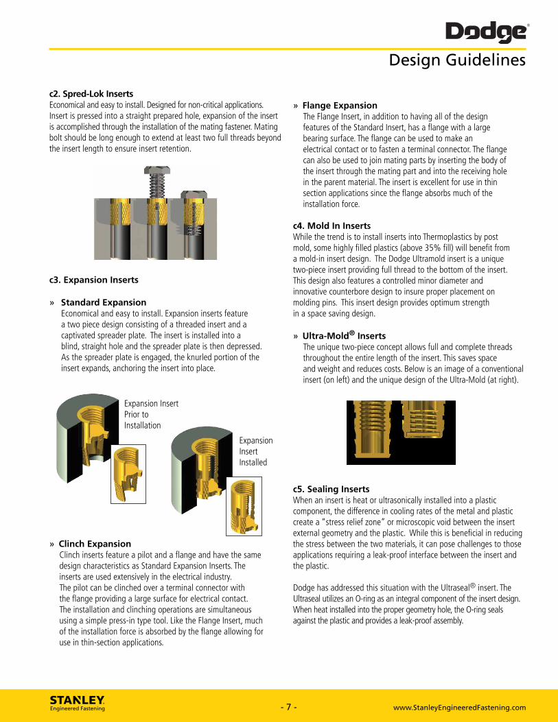
Standard Expansion Economical and easy to install. Expansion inserts feature a two piece design consisting of a threaded insert and a captivated spreader plate. The insert is installed into a blind, straight hole and the spreader plate is then depressed. As the spreader plate is engaged, the knurled portion of the insert expands, anchoring the insert into place.
» Clinch Expansion Clinch inserts feature a pilot and a flange and have the same design characteristics as Standard Expansion Inserts. The inserts are used extensively in the electrical industry. The pilot can be clinched over a terminal connector with the flange providing a large surface for electrical contact. The installation and clinching operations are simultaneous using a simple press-in type tool. Like the Flange Insert, much of the installation force is absorbed by the flange allowing for use in thin-section applications.
Flange Expansion The Flange Insert, in addition to having all of the design features of the Standard Insert, has a flange with a large bearing surface. The flange can be used to make an electrical contact or to fasten a terminal connector. The flange can also be used to join mating parts by inserting the body of the insert through the mating part and into the receiving hole in the parent material. The insert is excellent for use in thin section applications since the flange absorbs much of the installation force.
c4. Mold In Inserts While the trend is to install inserts into Thermoplastics by post mold, some highly filled plastics (above 35% fill) will benefit from a mold-in insert design. The Dodge Ultramold insert is a unique two-piece insert providing full thread to the bottom of the insert. This design also features a controlled minor diameter and innovative counterbore design to insure proper placement on molding pins. This insert design provides optimum strength in a space saving design.
Ultra-Mold® Inserts The unique two-piece concept allows full and complete threads throughout the entire length of the insert. This saves space and weight and reduces costs. Below is an image of a conventional insert (on left) and the unique design of the Ultra-Mold (at right).
c5. Sealing Inserts When an insert is heat or ultrasonically installed into a plastic component, the difference in cooling rates of the metal and plastic create a "stress relief zone" or microscopic void between the insert external geometry and the plastic. While this is beneficial in reducing the stress between the two materials, it can pose challenges to those applications requiring a leak-proof interface between the insert and the plastic.
Dodge has addressed this situation with the Ultraseal® insert. The Ultraseal utilizes an 0-ring as an integral component of the insert design. When heat installed into the proper geometry hole, the 0-ring seals against the plastic and provides a leak-proof assembly.
STANLEY. Engineered Fastening - 7 - www.StanleyEngineeredFastening.com - 7 - www.StanleyEngineeredFastening.com
c2. Spred-Lok InsertsEconomical and easy to install. Designed for non-critical applications. Insert is pressed into a straight prepared hole, expansion of the insert is accomplished through the installation of the mating fastener. Mating bolt should be long enough to extend at least two full threads beyond the insert length to ensure insert retention.
c3. Expansion Inserts
» Standard Expansion Economical and easy to install. Expansion inserts feature a two piece design consisting of a threaded insert and a captivated spreader plate. The insert is installed into a blind, straight hole and the spreader plate is then depressed. As the spreader plate is engaged, the knurled portion of the insert expands, anchoring the insert into place.
» Clinch Expansion Clinch inserts feature a pilot and a flange and have the same design characteristics as Standard Expansion Inserts. The inserts are used extensively in the electrical industry. The pilot can be clinched over a terminal connector with the flange providing a large surface for electrical contact. The installation and clinching operations are simultaneous using a simple press-in type tool. Like the Flange Insert, much of the installation force is absorbed by the flange allowing for use in thin-section applications.
» Flange Expansion The Flange Insert, in addition to having all of the design features of the Standard Insert, has a flange with a large bearing surface. The flange can be used to make an electrical contact or to fasten a terminal connector. The flange can also be used to join mating parts by inserting the body of the insert through the mating part and into the receiving hole in the parent material. The insert is excellent for use in thin section applications since the flange absorbs much of the installation force.
c4. Mold In InsertsWhile the trend is to install inserts into Thermoplastics by post mold, some highly filled plastics (above 35% fill) will benefit from a mold-in insert design. The Dodge Ultramold insert is a unique two-piece insert providing full thread to the bottom of the insert. This design also features a controlled minor diameter and innovative counterbore design to insure proper placement on molding pins. This insert design provides optimum strength in a space saving design.
» Ultra-Mold® Inserts The unique two-piece concept allows full and complete threads throughout the entire length of the insert. This saves space and weight and reduces costs. Below is an image of a conventional insert (on left) and the unique design of the Ultra-Mold (at right).
c5. Sealing InsertsWhen an insert is heat or ultrasonically installed into a plastic component, the difference in cooling rates of the metal and plasticcreate a “stress relief zone” or microscopic void between the insert external geometry and the plastic. While this is beneficial in reducing the stress between the two materials, it can pose challenges to those applications requiring a leak-proof interface between the insert and the plastic.
Dodge has addressed this situation with the Ultraseal® insert. The Ultraseal utilizes an O-ring as an integral component of the insert design. When heat installed into the proper geometry hole, the O-ring seals against the plastic and provides a leak-proof assembly.
Expansion Insert Prior to Installation
Expansion InsertInstalled
Design Guidelines

Dodge® Applications
Dodge Inserts and Compression Limiters are widely used in critical applications in the automotive, electronics, medical, transportation and general industrial markets.
Aircraft Threaded Inserts for Plastic Components In the overhead aircraft interiors, brass inserts are used to strengthen and maintain joint integrity in brittle and soft material extending service life and value.
Automotive Air Intake Manifold Using the TaperTuff® and Ultrasert® in the intake manifold allows the OEM to create strong reusable threads that eliminated cracking from bolt load.
Automotive Grab Handle Using Compression Limiters eliminates cracking of plastic sub-component automotive interior parts due to bolt loading. The Dodge Compression limiter significantly reduces the warranty and replacement costs.
Automotive Sunroof Assembly A key component in the sunroof sub assembly is the power actuating motor. OEM's rely on the Dodge Ultrasert® for mounting the motor to the frame for both stability and high quality.
Electronics Cell Phone Housing Assembly Dodge's unique line of Miniature Inserts are used in the Smartphone industry to mate the two plastic outer housings together, resulting in a structural assembly with long service life.
Electronics GPS Enclosure GPS Tracking and security devices require consistency and reliability. Manufacturers of GPS assemblies turn to Ultrasert® for quality and reliable fastening every time.
STANLEY. Engineered Fastening - 8 - www.StanleyEngineeredFastening.com - 8 - www.StanleyEngineeredFastening.com
Applications
AircraftThreaded Inserts for Plastic ComponentsIn the overhead aircraft interiors, brass inserts are used to strengthen and maintain joint integrity in brittle and soft material extending service life and value.
Automotive Air Intake ManifoldUsing the TaperTuff® and Ultrasert® in the intake manifold allows the OEM to create strong reusable threads that eliminated cracking from bolt load.
Automotive Grab HandleUsing Compression Limiters eliminates cracking of plastic sub-component automotive interior parts due to bolt loading. The Dodge Compression limiter significantly reduces the warranty and replacement costs.
Automotive Sunroof AssemblyA key component in the sunroof sub assembly is the power actuating motor. OEM’s rely on the Dodge Ultrasert® for mounting the motor to the frame for both stability and high quality.
ElectronicsCell Phone Housing AssemblyDodge’s unique line of Miniature Inserts are used in the Smartphone industry to mate the two plastic outer housings together, resulting in a structural assembly with long service life.
Electronics GPS EnclosureGPS Tracking and security devices require consistency and reliability. Manufacturers of GPS assemblies turn to Ultrasert® for quality and reliable fastening every time.
Dodge Inserts and Compression Limiters are widely used in critical applications in the automotive, electronics, medical, transportation and general industrial markets.
Dodge® Applications
Industrial Appliance Fan Module Manufacturers of fan modules around the world depend upon Dodge Ultrasert® brass inserts for reliability and performance.
Industrial Power Tool Housing Power tool manufacturers count on the Dodge Ultrasert® to provide the superior joint strength, vibration proof properties and high serviceability required of their products.
Industrial Pump Housing Multiple Ultrasert® inserts are used in pump assemblies to provide high shear, tensile and torque necessary to handle the load of the fluctuating stresses in the application.
Lawn and Garden Engine and Component Assembly In the high vibration world of lawn and garden equipment, the high strength characteristics of the Ultrasert® inserts provide superior retention in brittle and soft materials when fastening plastic components to the engine.
Medical Medical Device Enclosure The Dodge Ultrasert® line of threaded inserts are utilized to maintain joint integrity when assembling critical component parts in many types of medical equipment.
STANLEY. Engineered Fastening - 9 - www.StanleyEngineeredFastening.com - 9 - www.StanleyEngineeredFastening.com
Applications
Industrial Appliance Fan ModuleManufacturers of fan modules around the world depend upon Dodge Ultrasert® brass inserts for reliability and performance.
Industrial Power Tool HousingPower tool manufacturers count on the Dodge Ultrasert® to provide the superior joint strength, vibration proof properties and high serviceability required of their products.
Industrial Pump HousingMultiple Ultrasert® inserts are used in pump assemblies to provide high shear, tensile and torque necessary to handle the load of the fluctuating stresses in the application.
Lawn and GardenEngine and Component AssemblyIn the high vibration world of lawn and garden equipment, the high strength characteristics of the Ultrasert® inserts provide superior retention in brittle and soft materials when fastening plastic components to the engine.
MedicalMedical Device EnclosureThe Dodge Ultrasert® line of threaded inserts are utilized to maintain joint integrity when assembling critical component parts in many types of medical equipment.
400111&--,, 400 101 a Gib
Dodge®
Dodge Capabilities
Quality » ISO/TS 16949: 2009 certified » Lot control ensures product traceability » Statistically controlled manufacturing processes » PPAP, IMDS, Material Certifications
Sales & Applications Engineers Strategically located throughout North America Offer expertise in insert design, applications engineering and current assembly technologies Offer cost effective fastening solutions; includes: — Modifications to our standard products — Custom solutions for your specific applications — Conduct Line Walks, Value Analysis /Value Engineering
Product Development Our Technical Center offers review of your application, product evaluation, analysis and recommendations to help reduce your assembly costs Development support includes conceptual ideas, preliminary designs and drawings Engineering prototypes and pre-production sampling resources available
Technical Product Seminars Lunch and Learn Seminars offered to engineering, manufacturing, purchasing and quality teams Instructors include representatives from our sales engineering, applications engineering and/or marketing teams
Testing Terminology
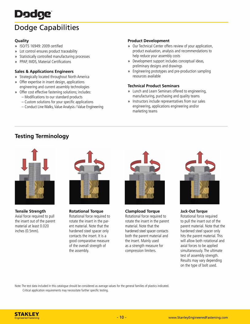
Tensile Strength Axial force required to pull the insert out of the parent material at least 0.020 inches (0.5mm).
Rotational Torque Rotational force required to rotate the insert in the par-ent material. Note that the hardened steel spacer only contacts the insert. It is a good comparative measure of the overall strength of the assembly.
Clampload Torque Rotational force required to rotate the insert in the parent material. Note that the hardened steel spacer contacts both the parent material and the insert. Mainly used as a strength measure for compression limiters.
Jack-Out Torque Rotational force required to pull the insert out of the parent material. Note that the hardened steel spacer only hits the parent material. This will allow both rotational and axial forces to be applied simultaneously. The ultimate test of assembly strength. Results may vary depending on the type of bolt used.
Note: The test data included in this catalogue should be considered as average values for the general families of plastics indicated. Critical application requirements may necessitate further specific testing.
STANLEY. Engineered Fastening - 10 - www.StanleyEngineeredFastening.com - 10 - www.StanleyEngineeredFastening.com
Dodge Capabilities
Tensile StrengthAxial force required to pull the insert out of the parent material at least 0.020 inches (0.5mm).
Rotational TorqueRotational force required to rotate the insert in the par-ent material. Note that the hardened steel spacer only contacts the insert. It is a good comparative measure of the overall strength of the assembly.
Jack-Out TorqueRotational force required to pull the insert out of the parent material. Note that the hardened steel spacer only hits the parent material. This will allow both rotational and axial forces to be applied simultaneously. The ultimate test of assembly strength. Results may vary depending on the type of bolt used.
Clampload TorqueRotational force required to rotate the insert in the parent material. Note that the hardened steel spacer contacts both the parent material and the insert. Mainly used as a strength measure for compression limiters.
Quality» ISO/TS 16949: 2009 certified» Lot control ensures product traceability» Statistically controlled manufacturing processes» PPAP, IMDS, Material Certifications
Sales & Applications Engineers» Strategically located throughout North America» Offer expertise in insert design, applications engineering and current assembly technologies» Offer cost effective fastening solutions; includes: – Modifications to our standard products – Custom solutions for your specific applications – Conduct Line Walks, Value Analysis / Value Engineering
Product Development» Our Technical Center offers review of your application, product evaluation, analysis and recommendations to help reduce your assembly costs» Development support includes conceptual ideas, preliminary designs and drawings » Engineering prototypes and pre-production sampling resources available
Technical Product Seminars» Lunch and Learn Seminars offered to engineering, manufacturing, purchasing and quality teams» Instructors include representatives from our sales engineering, applications engineering and/or marketing teams
Testing Terminology
Note: The test data included in this catalogue should be considered as average values for the general families of plastics indicated. Critical application requirements may necessitate further specific testing.
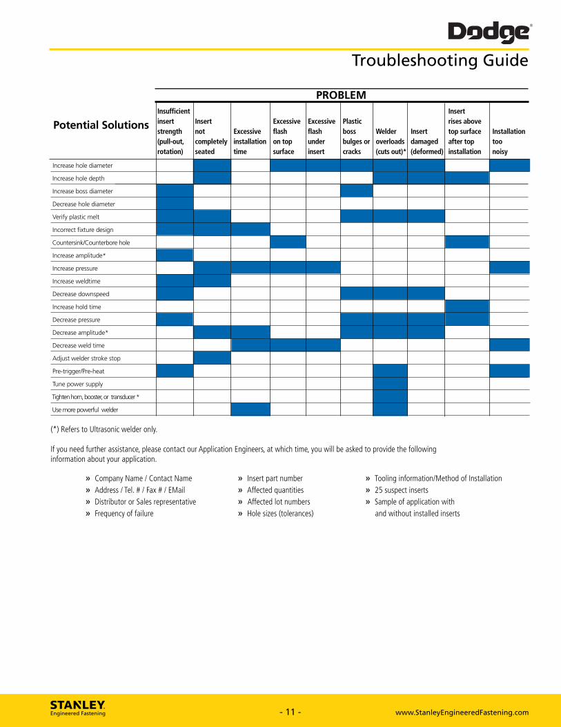
Dodge® Troubleshooting Guide
PROBLEM
Potential Solutions Insufficient insert strength (pull-out, rotation)
Insert not completely seated
Excessive installation time
Excessive flash on top surface
Excessive flash under insert
Plastic boss bulges or cracks
Welder overloads (cuts out)*
Insert damaged (deformed)
Insert rises above top surface after top installation
Installation too noisy
Increase hole diameter 11111
Increase hole depth
Increase boss diameter
Decrease hole diameter
Verify plastic melt
Incorrect fixture design
Countersink/Counterbore hole
Increase amplitude*
Increase pressure
Increase weldtime
Decrease downspeed
Increase hold time
Decrease pressure
Decrease amplitude*
Decrease weld time
Adjust welder stroke stop
Pre-trigger/Pre-heat
Tune power supply
Tighten horn, booster, or transducer"
Use more powerful welder
(*) Refers to Ultrasonic welder only.
If you need further assistance, please contact our Application Engineers, at which time, you will be asked to provide the following information about your application.
» Company Name / Contact Name » Insert part number » Tooling information/Method of Installation » Address /Tel. # / Fax # / EMail
» Affected quantities » 25 suspect inserts
» Distributor or Sales representative » Affected lot numbers » Sample of application with » Frequency of failure » Hole sizes (tolerances)
and without installed inserts
STANLEY. Engineered Fastening - 11 - www.Stan leyEng ineeredFastening.com - 11 - www.StanleyEngineeredFastening.com
Increase hole diameter
Increase hole depth
Increase boss diameter
Decrease hole diameter
Verify plastic melt
Incorrect fixture design
Countersink/Counterbore hole
Increase amplitude*
Increase pressure
Increase weldtime
Decrease downspeed
Increase hold time
Decrease pressure
Decrease amplitude*
Decrease weld time
Adjust welder stroke stop
Pre-trigger/Pre-heat
Tune power supply
Tighten horn, booster, or transducer *
Use more powerful welder
Insufficient Insertinsert Insert Excessive Excessive Plastic rises abovestrength not Excessive flash flash boss Welder Insert top surface Installation(pull-out, completely installation on top under bulges or overloads damaged after top toorotation) seated time surface insert cracks (cuts out)* (deformed) installation noisy
PROBLEM
Potential Solutions
Troubleshooting Guide
(*) Refers to Ultrasonic welder only.
If you need further assistance, please contact our Application Engineers, at which time, you will be asked to provide the following information about your application.
» Company Name / Contact Name » Insert part number » Tooling information/Method of Installation» Address / Tel. # / Fax # / EMail » Affected quantities » 25 suspect inserts» Distributor or Sales representative » Affected lot numbers » Sample of application with » Frequency of failure » Hole sizes (tolerances) and without installed inserts
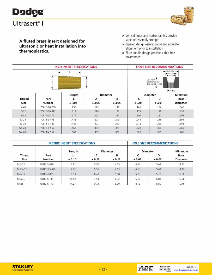
Dodge® Ultrasert® I
A fluted brass insert designed for ultrasonic or heat installation into thermoplastics.
r-r-rry.
» Vertical flutes and horizontal fins provide superior assembly strength
» Tapered design assures rapid and accurate alignment prior to installation
» Flute and fin design provide a chip-free environment
INCH INSERT SPECIFICATIONS HOLE SIZE RECOMMENDATIONS
Thread Size
L
MM. Insert .030
Min. Boss
1
01
(")->--):/1 1
1.4EC*
pia
Minimum Boss
Diameter
Depth tk Length Plus
Inch (0.77mm)
Part Number
Length Diameter Diameter
± .004 A
± .005 B
± .005 C
± .001 D
± .001 4-40 70815-04-250 .250 .173 .145 .141 .154 .346
6-32 70815-06-312 .312 .219 .183 .179 .198 .438
8-32 70815-2-375 .375 .252 .212 .206 .227 .504
10-24 70815-3-438 .438 .297 .249 .243 .268 .594
10-32 70811-3-438 .438 .297 .249 .243 .268 .594
1/4-20 70815-4-562 .562 .383 .323 .320 .350 .766
1/4-28 70811-4-562 .562 .383 .323 .320 .350 .766
METRIC INSERT SPECIFICATIONS HOLE SIZE RECOMMENDATIONS
Length Diameter Diameter Minimum Thread Part L A B C D Boss
Size Number ± 0.10 ± 0.13 ± 0.13 ± 0.03 ± 0.03 Diameter
M3x0.5 70817-3-079 7.92 5.56 4.65 4.55 5.03 11.12
M3.5x0.6 70817-3.5-079 7.92 5.56 4.65 4.55 5.03 11.12
M4x0.7 70817-4-095 9.53 6.40 5.38 5.23 5.77 12.80
M5x0.8 70817-5-111 11.13 7.54 6.32 6.17 6.81 15.08
M6x1 70817-6-143 14.27 9.73 8.20 8.13 8.89 19.46
STANLEY. Engineered Fastening - 12 - www.StanleyEngineeredFastening.com - 12 - www.StanleyEngineeredFastening.com
Ultrasert® I
METRIC INSERT SPECIFICATIONS HOLE SIZE RECOMMENDATIONS
Length Diameter Diameter Minimum Thread Part L A B C D Boss Size Number ± 0.10 ± 0.13 ± 0.13 ± 0.03 ± 0.03 Diameter
M3x0.5 70817-3-079 7.92 5.56 4.65 4.55 5.03 11.12
M3.5x0.6 70817-3.5-079 7.92 5.56 4.65 4.55 5.03 11.12
M4x0.7 70817-4-095 9.53 6.40 5.38 5.23 5.77 12.80
M5x0.8 70817-5-111 11.13 7.54 6.32 6.17 6.81 15.08
M6x1 70817-6-143 14.27 9.73 8.20 8.13 8.89 19.46
A fluted brass insert designed for ultrasonic or heat installation into thermoplastics.
INCH INSERT SPECIFICATIONS HOLE SIZE RECOMMENDATIONS
Length Diameter Diameter Minimum Thread Part L A B C D Boss Size Number ± .004 ± .005 ± .005 ± .001 ± .001 Diameter
4-40 70815-04-250 .250 .173 .145 .141 .154 .346
6-32 70815-06-312 .312 .219 .183 .179 .198 .438
8-32 70815-2-375 .375 .252 .212 .206 .227 .504
10-24 70815-3-438 .438 .297 .249 .243 .268 .594
10-32 70811-3-438 .438 .297 .249 .243 .268 .594
1/4-20 70815-4-562 .562 .383 .323 .320 .350 .766
1/4-28 70811-4-562 .562 .383 .323 .320 .350 .766
A
L
BMin. Depth = Insert Length Plus .030 Inch (0.77mm)
C
Min. Boss Dia8˚D
» Vertical flutes and horizontal fins provide superior assembly strength» Tapered design assures rapid and accurate alignment prior to installation» Flute and fin design provide a chip-free environment
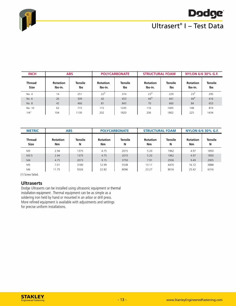
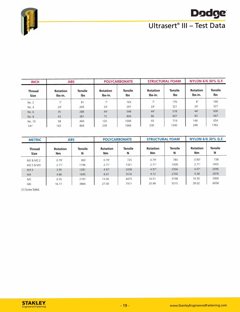
Dodge® Ultrasert® I — Test Data
INCH ABS POLYCARBONATE STRUCTURAL FOAM NYLON 6/6 30% G.F.
Thread Size
Rotation lbs-in.
Tensile
lbs
Rotation lbs-in.
Tensile
lbs
Rotation lbs-in.
Tensile
lbs Rotation
lbs-in. Tensile
lbs
No. 4 14 251 22f 374 23f 229 23f 295
No. 6
No. 8
26
42
309
466
42
81
453
843
44f
70
441
660
44t
84
416
653
No. 10
1/4"
62
104
715
1130
115
202
1245
1820
116
206
1005
1802
148
225
874
1434
METRIC ABS POLYCARBONATE STRUCTURAL FOAM NYLON 6/6 30% G.F.
Thread Size
Rotation Nm
Tensile
N Rotation
Nm
Tensile
N Rotation
Nm
Tensile
N Rotation
Nm
Tensile
N
M3 2.94 1375 4.75 2015 5.20 1962 4.97 1850
M3.5
M4
2.94
4.75
1375
2073
4.75
9.15
2015
3750
5.20
7.91
1962
2936
4.97
9.49
1850
2905
M5
M6
7.01
11.75
3180
5026
12.99
22.82
5538
8096
13.11
23.27
4470
8016
16.72
25.42
3888
6316
(t) Screw failed.
Ultraserts Dodge Ultraserts can be installed using ultrasonic equipment or thermal installation equipment . Thermal equipment can be as simple as a soldering iron held by hand or mounted in an arbor or drill press. More refined equipment is available with adjustments and settings for precise uniform installations.
STANLEY. Engineered Fastening - 13 - www.StanleyEngineeredFastening.com - 13 - www.StanleyEngineeredFastening.com
INCH ABS POLYCARBONATE STRUCTURAL FOAM NYLON 6/6 30% G.F. Thread Rotation Tensile Rotation Tensile Rotation Tensile Rotation Tensile Size lbs-in. lbs lbs-in. lbs lbs-in. lbs lbs-in. lbs
No. 4 14 251 22† 374 23† 229 23† 295
No. 6 26 309 42 453 44† 441 44† 416
No. 8 42 466 81 843 70 660 84 653
No. 10 62 715 115 1245 116 1005 148 874
1/4” 104 1130 202 1820 206 1802 225 1434
Ultrasert® I – Test Data
METRIC ABS POLYCARBONATE STRUCTURAL FOAM NYLON 6/6 30% G.F. Thread Rotation Tensile Rotation Tensile Rotation Tensile Rotation Tensile Size Nm N Nm N Nm N Nm N
M3 2.94 1375 4.75 2015 5.20 1962 4.97 1850
M3.5 2.94 1375 4.75 2015 5.20 1962 4.97 1850
M4 4.75 2073 9.15 3750 7.91 2936 9.49 2905
M5 7.01 3180 12.99 5538 13.11 4470 16.72 3888
M6 11.75 5026 22.82 8096 23.27 8016 25.42 6316
(†) Screw failed.
UltrasertsDodge Ultraserts can be installed using ultrasonic equipment or thermal installation equipment . Thermal equipment can be as simple as a soldering iron held by hand or mounted in an arbor or drill press. More refined equipment is available with adjustments and settings for precise uniform installations.
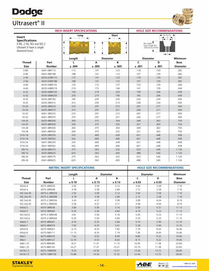
Dodge® Ultrasert® II
.172 .157
.146
.135
.172 .219
.230
.213 .312 .250
.185 .250
.297 .225 .272
.251 .297 .375
.375 .300 .354
.332 .375 .500
.439
.406 .562 .469
.335 .469
STANLEY. Engineered Fastening - 14 - www.StanleyEngineeredFastening.com
INCH INSERT SPECIFICATIONS HOLE SIZE RECOMMENDATIONS
Insert Specifications 0-80, 2-56, M2 and M2.2 Ultrasert II have a single diamond knurl.
Thread Size
Part Number
0-80
0-80
6041-0BR115
6041-0BR188
2-56 6035-02BR115
2-56 6035-02BR188
4-40 6035-04BR135
4-40 6035-04BR219
6-32 6035-06BR150
6-32 6035-06BR250
8-32 6035-2BR185
8-32 6035-2BR312
10-24 6035-3BR225 10-24 6035-3BR375
10-32 6041-3BR225
10-32 6041-3BR375
1/4-20 6035-4BR300 1/4-20 6035-4BR500
1/4-28 6041-4BR300
1/4-28 6041-4BR500
5/16-18 6035-5BR335
5/16-18 6035-5BR562
5/16-24 6041-5BR335
5/16-24 6041-5BR562
3/8-16 6035-6BR375
3/8-16 6035-6BR625
3/8-24 6041-6BR375
3/8-24 6041-6BR625
Min. Depth t' Insert Length Plus .030 Inch (0.77mm)
Minimum Boss
Diameter
Diameter
EC-*
± .001 D
± .001 .118
.107
.129
.129
.282
.282
.118 .129 .282
.107 .129 .282
.153 .159 .344
.141 .159 .344
.199 .206 .438
.185 .206 .438
.226 .234 .500
.208 .234 .500
.267 .277 .594
.246 .277 .594
.267 .277 .594
.246 .277 .594
.349 .363 .750
.321 .363 .750
.349 .363 .750
.321 .363 .750
.431 .448 .938
.401 .448 .938
.431 .448 .938
.401 .448 .938
.523 .540 1.126
.488 .540 1.126
.523 .540 1.126
.488 .540 1.126
Length
± .004
Min. Boss pia 1.1( \1.4-D-)1.1/
-7
.115
.188
.141
.141
.123
.112
.150
.250
.219
.219 .203
.190
.225
.375
.297
.297
.272
.251
.300
.500
.375
.375
.354
.332
.335
.562
.469
.469
.439
.406
.375
.625
.563
.563
.532
.493
METRIC INSERT SPECIFICATIONS HOLE SIZE RECOMMENDATIONS
Thread Size
Part Number
Length Diameter Diameter Minimum Boss
Diameter L
± 0.10 A
± 0.13 B
± 0.13 C
± 0.03 D
± 0.03 M2x0.4 6075-2 BRO29 2.92 3.58 3.12 3.00 3.28 7.16
M2x0.4 6075-2 BRO48 4.78 3.58 2.84 2.72 3.28 7.16
M2.2x0.45 6075-2.2BR029 2.92 3.58 3.12 3.00 3.28 7.16
M2.2x0.45 6075-2.2BR048 4.78 3.58 2.84 2.72 3.28 7.16
M2.5x0.45 6075-2.5BR034 3.43 4.37 3.99 3.89 4.04 8.74
M2.5x0.45 6075-2.5BR056 5.56 4.37 3.71 3.58 4.04 8.74
M3x0.5 6075-3BR038 3.80 5.56 5.16 5.05 5.31 11.13
M3x0.5 6075-3BR064 6.35 5.56 4.83 4.70 5.23 11.13
M3.5x0.6 6075-3.5BR038 3.81 5.56 5.16 5.05 5.23 11.13
M3.5x0.6 6075-3.5BR064 6.35 5.56 4.83 4.70 5.23 11.13
M4x0.7 6075-4BR047 4.70 6.35 5.84 5.74 5.94 12.70
M4x0.7 6075-4BR079 7.92 6.35 5.41 5.28 5.94 12.70
M5x0.8 6075-5BR067 6.73 8.33 7.82 7.70 8.00 16.66
M5x0.8 6075-5BR111 11.13 8.33 7.19 7.06 8.00 16.66
M6x1 6075-6BR076 7.62 9.52 8.99 8.86 9.22 19.06
M6x1 6075-6BR127 12.70 9.53 8.43 8.15 9.22 19.06
M8x1.25 6075-8BR085 8.51 11.91 11.15 10.95 11.38 23.83 M8x1.25 6075-8BR143 14.27 11.91 10.31 10.19 11.38 23.83
M10x1.5 6075-10BR095 9.53 14.30 13.51 13.28 13.72 28.60
M10x1.5 6075-10BR159 15.88 14.30 12.52 12.40 13.72 28.60
.532
.493
.375
.625
.563
.563
Long L
.115
.188
A ± .005
.141
.141
Short L -)1.1
Diameter B
± .005 .123
.112
- 14 - www.StanleyEngineeredFastening.com
Ultrasert® II
A
L
B A
L
B
Long Short
INCH INSERT SPECIFICATIONS HOLE SIZE RECOMMENDATIONS
Length Diameter Diameter Minimum Thread Part L A B C D Boss Size Number ± .004 ± .005 ± .005 ± .001 ± .001 Diameter 0-80 6041-0BR115 .115 .141 .123 .118 .129 .282
0-80 6041-0BR188 .188 .141 .112 .107 .129 .282
2-56 6035-02BR115 .115 .141 .123 .118 .129 .282
2-56 6035-02BR188 .188 .141 .112 .107 .129 .282
4-40 6035-04BR135 .135 .172 .157 .153 .159 .344
4-40 6035-04BR219 .219 .172 .146 .141 .159 .344
6-32 6035-06BR150 .150 .219 .203 .199 .206 .438
6-32 6035-06BR250 .250 .219 .190 .185 .206 .438
8-32 6035-2BR185 .185 .250 .230 .226 .234 .500
8-32 6035-2BR312 .312 .250 .213 .208 .234 .500
10-24 6035-3BR225 .225 .297 .272 .267 .277 .594
10-24 6035-3BR375 .375 .297 .251 .246 .277 .594
10-32 6041-3BR225 .225 .297 .272 .267 .277 .594
10-32 6041-3BR375 .375 .297 .251 .246 .277 .594
1/4-20 6035-4BR300 .300 .375 .354 .349 .363 .750
1/4-20 6035-4BR500 .500 .375 .332 .321 .363 .750
1/4-28 6041-4BR300 .300 .375 .354 .349 .363 .750
1/4-28 6041-4BR500 .500 .375 .332 .321 .363 .750
5/16-18 6035-5BR335 .335 .469 .439 .431 .448 .938
5/16-18 6035-5BR562 .562 .469 .406 .401 .448 .938
5/16-24 6041-5BR335 .335 .469 .439 .431 .448 .938
5/16-24 6041-5BR562 .562 .469 .406 .401 .448 .938
3/8-16 6035-6BR375 .375 .563 .532 .523 .540 1.126
3/8-16 6035-6BR625 .625 .563 .493 .488 .540 1.126
3/8-24 6041-6BR375 .375 .563 .532 .523 .540 1.126
3/8-24 6041-6BR625 .625 .563 .493 .488 .540 1.126
METRIC INSERT SPECIFICATIONS HOLE SIZE RECOMMENDATIONS
Length Diameter Diameter Minimum Thread Part L A B C D Boss Size Number ± 0.10 ± 0.13 ± 0.13 ± 0.03 ± 0.03 Diameter M2x0.4 6075-2BR029 2.92 3.58 3.12 3.00 3.28 7.16
M2x0.4 6075-2BR048 4.78 3.58 2.84 2.72 3.28 7.16
M2.2x0.45 6075-2.2BR029 2.92 3.58 3.12 3.00 3.28 7.16
M2.2x0.45 6075-2.2BR048 4.78 3.58 2.84 2.72 3.28 7.16
M2.5x0.45 6075-2.5BR034 3.43 4.37 3.99 3.89 4.04 8.74
M2.5x0.45 6075-2.5BR056 5.56 4.37 3.71 3.58 4.04 8.74
M3x0.5 6075-3BR038 3.80 5.56 5.16 5.05 5.31 11.13
M3x0.5 6075-3BR064 6.35 5.56 4.83 4.70 5.23 11.13
M3.5x0.6 6075-3.5BR038 3.81 5.56 5.16 5.05 5.23 11.13
M3.5x0.6 6075-3.5BR064 6.35 5.56 4.83 4.70 5.23 11.13
M4x0.7 6075-4BR047 4.70 6.35 5.84 5.74 5.94 12.70
M4x0.7 6075-4BR079 7.92 6.35 5.41 5.28 5.94 12.70
M5x0.8 6075-5BR067 6.73 8.33 7.82 7.70 8.00 16.66
M5x0.8 6075-5BR111 11.13 8.33 7.19 7.06 8.00 16.66
M6x1 6075-6BR076 7.62 9.52 8.99 8.86 9.22 19.06
M6x1 6075-6BR127 12.70 9.53 8.43 8.15 9.22 19.06
M8x1.25 6075-8BR085 8.51 11.91 11.15 10.95 11.38 23.83
M8x1.25 6075-8BR143 14.27 11.91 10.31 10.19 11.38 23.83
M10x1.5 6075-10BR095 9.53 14.30 13.51 13.28 13.72 28.60
M10x1.5 6075-10BR159 15.88 14.30 12.52 12.40 13.72 28.60
InsertSpecifications0-80, 2-56, M2 and M2.2Ultrasert II have a singlediamond knurl.
Min. Depth = Insert Length Plus .030 Inch (0.77mm)
C
Min. Boss Dia8˚D
Dodge® Ultrasert® II -Test Data
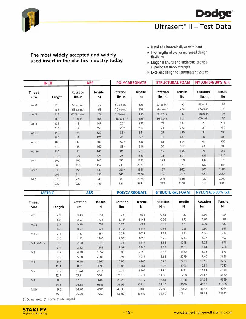
The most widely accepted and widely used insert in the plastics industry today.
» Installed ultrasonically or with heat » Two lengths allow for increased design
flexibility » Diagonal knurls and undercuts provide
superior assembly strength » Excellent design for automated systems
INCH ABS POLYCARBONATE STRUCTURAL FOAM NYLON 6/6 30% G.F.
Thread Rotation Tensile Rotation Tensile Rotation Tensile Rotation Tensile
Size Length lbs-in. lbs lbs-in. lbs lbs-in. lbs lbs-in. lbs
No. 0 .115 50 oz-in.* 79 52 oz-in.* 135 52 oz-in.t 97 58 oz-in. 96
.188 65 oz-in.* 162 70 oz-in.* 258 70 oz-in.* 224 65 oz-in. 198
No. 2 .115 67.5 oz-in. 79 110 oz-in. 135 90 oz-in. 97 58 oz-in. 96
.188 81 oz-in. 162 168 oz-in. t 258 93 oz-in. 224 65 oz-in. 198
No. 4 .135 13 147 20* 230 19 187 20 211
.219 17 258 23* 417 24 393 21 330
No. 6 .150 23 220 33* 341 29 236 33 286
.250 25 370 45 661 31 487 34 509
No. 8 .185 37 304 52* 538 32 304 60 355
.312 45 469 88* 910 50 512 66 883
No. 10 .225 51 448 86 773 55 505 70 565
.375 68 726 125 1388 72 801 133 1310
1/4" .300 102 700 157 1283 123 769 132 973
.500 116 1157 231 2073 131 1171 220 1884
5/16" .335 155 739 259* 1555 167 932 304 1506
.562 214 1435 345* 3128 196 1767 428 2654
3/8" .375 220 940 383 2065 246 1356 420 2040
.625 229 1743 520 3638 297 2100 518 3303
METRIC ABS POLYCARBONATE STRUCTURAL FOAM NYLON 6/6 30% G.F.
Thread Size Length
Rotation Nm
Tensile N
Rotation Nm
Tensile N
Rotation Nm
Tensile N
Rotation Nm
Tensile N
M2 2.9 0.48 351 0.78 601 0.63 429 0.90 427
4.8 0.57 721 1.19* 1148 0.66 995 0.90 881
M2.2 2.9 0.48 351 0.78 601 0.63 429 0.90 427
4.8 0.57 721 1.19* 1148 0.66 995 0.90 881
M2.5 3.4 1.47 654 2.26* 1023 2.23 834 2.26 939
5.6 1.92 1148 2.60* 1855 2.75 1748 2.37 1468
M3 & M3.5 3.8 2.60 979 3.73" 1517 3.35 1048 3.73 1272
6.4 2.82 1646 5.08 2940 3.54 2164 3.84 2264
M4 4.7 4.18 1352 5.88 2393 3.56 1350 6.78 1579
7.9 5.08 2086 9.94" 4048 5.65 2279 7.46 3928
M5 6.7 6.78 2260 10.85 4168 6.25 2723 13.55 3777
11.1 8.81 3599 15.82 6761 8.08 3903 19.54 7037
M6 7.6 11.52 3114 17.74 5707 13.84 3421 14.91 4328
12.7 13.11 5147 26.10 9221 14.80 5208 24.86 8380
M8 8.5 17.51 3287 29.26 6917 18.81 4146 34.35 6699
14.3 24.18 6383 38.98 13914 22.10 7860 48.36 11806
M10 9.5 24.90 4181 43.30 9186 27.80 6032 47.45 9074
15.9 25.90 7753 58.80 16183 33.60 9341 58.53 14692
(t) Screw failed. (Internal thread stripped.
STANLEY. Engineered Fastening - 15 - www.StanleyEngineeredFastening.com - 15 - www.StanleyEngineeredFastening.com
INCH ABS POLYCARBONATE STRUCTURAL FOAM NYLON 6/6 30% G.F.
Thread Rotation Tensile Rotation Tensile Rotation Tensile Rotation Tensile
Size Length lbs-in. lbs lbs-in. lbs lbs-in. lbs lbs-in. lbs No. 0 .115 50 oz-in.† 79 52 oz-in.† 135 52 oz-in.† 97 58 oz-in. 96
.188 65 oz-in.† 162 70 oz-in.† 258 70 oz-in.† 224 65 oz-in. 198
No. 2 .115 67.5 oz-in. 79 110 oz-in. 135 90 oz-in. 97 58 oz-in. 96
.188 81 oz-in. 162 168 oz-in. † 258 93 oz-in. 224 65 oz-in. 198
No. 4 .135 13 147 20* 230 19 187 20 211
.219 17 258 23* 417 24 393 21 330
No. 6 .150 23 220 33* 341 29 236 33 286
.250 25 370 45 661 31 487 34 509
No. 8 .185 37 304 52* 538 32 304 60 355
.312 45 469 88* 910 50 512 66 883
No. 10 .225 51 448 86 773 55 505 70 565
.375 68 726 125 1388 72 801 133 1310
1/4” .300 102 700 157 1283 123 769 132 973
.500 116 1157 231 2073 131 1171 220 1884
5/16” .335 155 739 259* 1555 167 932 304 1506
.562 214 1435 345* 3128 196 1767 428 2654
3/8” .375 220 940 383 2065 246 1356 420 2040
.625 229 1743 520 3638 297 2100 518 3303
METRIC ABS POLYCARBONATE STRUCTURAL FOAM NYLON 6/6 30% G.F.
Thread Rotation Tensile Rotation Tensile Rotation Tensile Rotation Tensile
Size Length Nm N Nm N Nm N Nm N
M2 2.9 0.48 351 0.78 601 0.63 429 0.90 427
4.8 0.57 721 1.19† 1148 0.66 995 0.90 881
M2.2 2.9 0.48 351 0.78 601 0.63 429 0.90 427
4.8 0.57 721 1.19† 1148 0.66 995 0.90 881
M2.5 3.4 1.47 654 2.26* 1023 2.23 834 2.26 939
5.6 1.92 1148 2.60* 1855 2.75 1748 2.37 1468
M3 & M3.5 3.8 2.60 979 3.73* 1517 3.35 1048 3.73 1272
6.4 2.82 1646 5.08 2940 3.54 2164 3.84 2264
M4 4.7 4.18 1352 5.88 2393 3.56 1350 6.78 1579
7.9 5.08 2086 9.94* 4048 5.65 2279 7.46 3928
M5 6.7 6.78 2260 10.85 4168 6.25 2723 13.55 3777
11.1 8.81 3599 15.82 6761 8.08 3903 19.54 7037
M6 7.6 11.52 3114 17.74 5707 13.84 3421 14.91 4328
12.7 13.11 5147 26.10 9221 14.80 5208 24.86 8380
M8 8.5 17.51 3287 29.26 6917 18.81 4146 34.35 6699
14.3 24.18 6383 38.98 13914 22.10 7860 48.36 11806
M10 9.5 24.90 4181 43.30 9186 27.80 6032 47.45 9074
15.9 25.90 7753 58.80 16183 33.60 9341 58.53 14692
Ultrasert® II – Test Data
The most widely accepted and widely used insert in the plastics industry today.
» Installed ultrasonically or with heat» Two lengths allow for increased design flexibility» Diagonal knurls and undercuts provide superior assembly strength» Excellent design for automated systems
(†) Screw failed. (*)Internal thread stripped.
Min. Depth Insert Length .030 Inch
Min. Boss Dia
FDA
4 Plus
0.77mm)
*-e* Diameter Diameter Minimum
A B C D Boss ± .005 ± .005 ± .001 ± .001 Diameter
.172 .146 .141 .159 .344
.219 .190 .185 .206 .438
.250 .213 .208 .234 .500
.297 .251 .246 .277 .594
.297 .251 .246 .277 .594
.375 .332 .321 .363 .750
.375 .332 .321 .363 .750
LE LEI
Length Thread
Size
4-40
Part Number
6035L-04BR219
6-32 6035L-06BR250
6035L-2BR312 8-32
6035L-3BR375
6041L-3BR375
10-24
10-32
6035L-4BR500
6041L-4BR500
1/4-20
1/4-28
± .004 .219
.250
.312
.375
.375
.500
.500
Dodge® dJ
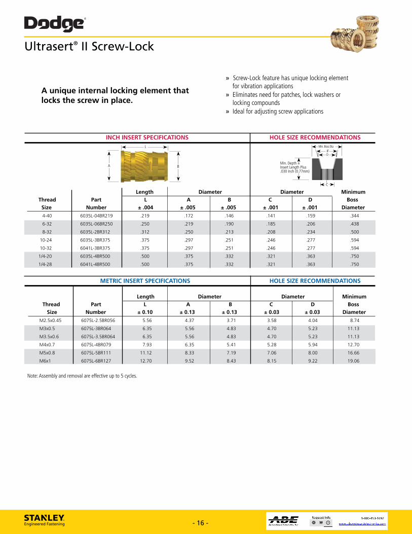
Ultrasert® II Screw-Lock
A unique internal locking element that locks the screw in place.
» Screw-Lock feature has unique locking element for vibration applications
» Eliminates need for patches, lock washers or locking compounds
» Ideal for adjusting screw applications
INCH INSERT SPECIFICATIONS
HOLE SIZE RECOMMENDATIONS
METRIC INSERT SPECIFICATIONS HOLE SIZE RECOMMENDATIONS
Length Diameter Diameter Minimum Thread Part L A B C D Boss
Size Number ± 0.10 ± 0.13 ± 0.13 ± 0.03 ± 0.03 Diameter
M2.5x0.45 6075L-2.5BR056 5.56 4.37 3.71 3.58 4.04 8.74
M3x0.5 6075L-3BR064 6.35 5.56 4.83 4.70 5.23 11.13
M3.5x0.6 6075L-3.5BR064 6.35 5.56 4.83 4.70 5.23 11.13
M4x0.7 6075L-4BR079 7.93 6.35 5.41 5.28 5.94 12.70
M5x0.8 6075L-5BR111 11.12 8.33 7.19 7.06 8.00 16.66
M6x1 6075L-6BR127 12.70 9.52 8.43 8.15 9.22 19.06
Note: Assembly and removal are effective up to 5 cycles.
STANLEY. Engineered Fastening - 16 - www.StanleyEngineeredFastening.com - 16 - www.StanleyEngineeredFastening.com
Ultrasert® II Screw-Lock
INCH INSERT SPECIFICATIONS HOLE SIZE RECOMMENDATIONS
Length Diameter Diameter Minimum Thread Part L A B C D Boss Size Number ± .004 ± .005 ± .005 ± .001 ± .001 Diameter
4-40 6035L-04BR219 .219 .172 .146 .141 .159 .344
6-32 6035L-06BR250 .250 .219 .190 .185 .206 .438
8-32 6035L-2BR312 .312 .250 .213 .208 .234 .500
10-24 6035L-3BR375 .375 .297 .251 .246 .277 .594
10-32 6041L-3BR375 .375 .297 .251 .246 .277 .594
1/4-20 6035L-4BR500 .500 .375 .332 .321 .363 .750
1/4-28 6041L-4BR500 .500 .375 .332 .321 .363 .750
METRIC INSERT SPECIFICATIONS HOLE SIZE RECOMMENDATIONS Length Diameter Diameter Minimum Thread Part L A B C D Boss Size Number ± 0.10 ± 0.13 ± 0.13 ± 0.03 ± 0.03 Diameter
M2.5x0.45 6075L-2.5BR056 5.56 4.37 3.71 3.58 4.04 8.74
M3x0.5 6075L-3BR064 6.35 5.56 4.83 4.70 5.23 11.13
M3.5x0.6 6075L-3.5BR064 6.35 5.56 4.83 4.70 5.23 11.13
M4x0.7 6075L-4BR079 7.93 6.35 5.41 5.28 5.94 12.70
M5x0.8 6075L-5BR111 11.12 8.33 7.19 7.06 8.00 16.66
M6x1 6075L-6BR127 12.70 9.52 8.43 8.15 9.22 19.06
A
L
BMin. Depth = Insert Length Plus .030 Inch (0.77mm)
C
Min. Boss Dia8˚D
A unique internal locking element that locks the screw in place.
» Screw-Lock feature has unique locking element for vibration applications» Eliminates need for patches, lock washers or locking compounds» Ideal for adjusting screw applications
Note: Assembly and removal are effective up to 5 cycles.
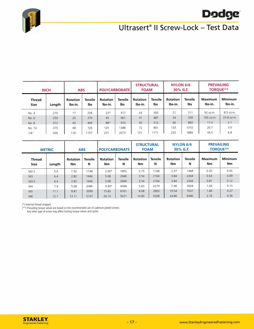
Dodge Ultrasert® II Screw-Lock - Test Data
INCH ABS POLYCARBONATE STRUCTURAL
FOAM NYLON 6/6
30% G.F.
PREVAILING TORQUE**
Thread Rotation Tensile Rotation Tensile Rotation Tensile Rotation Tensile Maximum Minimum
Size Length lbs-in. lbs lbs-in. lbs lbs-in. lbs lbs-in. lbs lbs-in. lbs-in.
No. 4 .219 17 258 23* 417 24 393 21 211 92 oz-in. 8.5 oz-in.
No. 6 .250 25 370 45 661 31 487 34 509 192 oz-in. 23.8 oz-in.
No. 8 .312 45 469 88* 910 50 512 66 883 17.3 2.1
No. 10 .375 68 726 125 1388 72 801 133 1310 20.7 3.0
1/4" .500 116 1157 231 2073 131 1171 220 1884 34.5 6.8
METRIC ABS POLYCARBONATE
STRUCTURAL FOAM
NYLON 6/6 30% G.F.
PREVAILING TORQUE**
Thread Rotation Tensile Rotation Tensile Rotation Tensile Rotation Tensile Maximum Minimum
Size Length Nm N Nm N Nm N Nm N Nm Nm
M2.5 5.6 1.92 1148 2.60* 1855 2.75 1748 2.37 1468 0.30 0.05
M3 6.4 2.82 1646 5.08 2940 3.54 2164 3.84 2264 0.63 0.09
M3.5 6.4 2.82 1646 5.08 2940 3.54 2164 3.84 2264 0.81 0.12
M4 7.9 5.08 2086 9.94" 4048 5.65 2279 7.46 3928 1.04 0.15
M5 11.1 8.81 3599 15.82 6761 8.08 3903 19.54 7037 1.84 0.27
M6 12.7 13.11 5147 26.10 9221 14.80 5208 24.86 8380 2.76 0.36
(*) Internal thread stripped. (**) Prevailing torque values are based on the recommended use of cadmium plated screws.
Any other type of screw may affect locking torque values and cycles.
STANLEY. Engineered Fastening - 17 - www.StanleyEngineeredFastening.com - 17 - www.StanleyEngineeredFastening.com
Ultrasert® II Screw-Lock – Test Data
STRUCTURAL NYLON 6/6 PREVAILING INCH ABS POLYCARBONATE FOAM 30% G.F. TORQUE**
Thread Rotation Tensile Rotation Tensile Rotation Tensile Rotation Tensile Maximum Minimum
Size Length lbs-in. lbs lbs-in. lbs lbs-in. lbs lbs-in. lbs lbs-in. lbs-in.
No. 4 .219 17 258 23* 417 24 393 21 211 92 oz-in. 8.5 oz-in.
No. 6 .250 25 370 45 661 31 487 34 509 192 oz-in. 23.8 oz-in.
No. 8 .312 45 469 88* 910 50 512 66 883 17.3 2.1
No. 10 .375 68 726 125 1388 72 801 133 1310 20.7 3.0
1/4” .500 116 1157 231 2073 131 1171 220 1884 34.5 6.8
STRUCTURAL NYLON 6/6 PREVAILING METRIC ABS POLYCARBONATE FOAM 30% G.F. TORQUE**
Thread Rotation Tensile Rotation Tensile Rotation Tensile Rotation Tensile Maximum Minimum
Size Length Nm N Nm N Nm N Nm N Nm Nm M2.5 5.6 1.92 1148 2.60* 1855 2.75 1748 2.37 1468 0.30 0.05
M3 6.4 2.82 1646 5.08 2940 3.54 2164 3.84 2264 0.63 0.09
M3.5 6.4 2.82 1646 5.08 2940 3.54 2164 3.84 2264 0.81 0.12
M4 7.9 5.08 2086 9.94* 4048 5.65 2279 7.46 3928 1.04 0.15
M5 11.1 8.81 3599 15.82 6761 8.08 3903 19.54 7037 1.84 0.27
M6 12.7 13.11 5147 26.10 9221 14.80 5208 24.86 8380 2.76 0.36
(*) Internal thread stripped.(**) Prevailing torque values are based on the recommended use of cadmium plated screws. Any other type of screw may affect locking torque values and cycles.
Length
Diameter
6-32 .281 .220 .440
8-32 .321 .250 .500
6635-06BR281
6635-2BR321
.185 .189
.218 .222
.684 .500 .316 .312 .342
.684 .500 .316 .312 .342
.562 .281 .375 10-24
10-32 .562 .253 .281 .375
6635-3BR375
6641-3BR375
.249 .253
.249
6635-4BR500
6641-4BR500
1/4-20
1/4-28
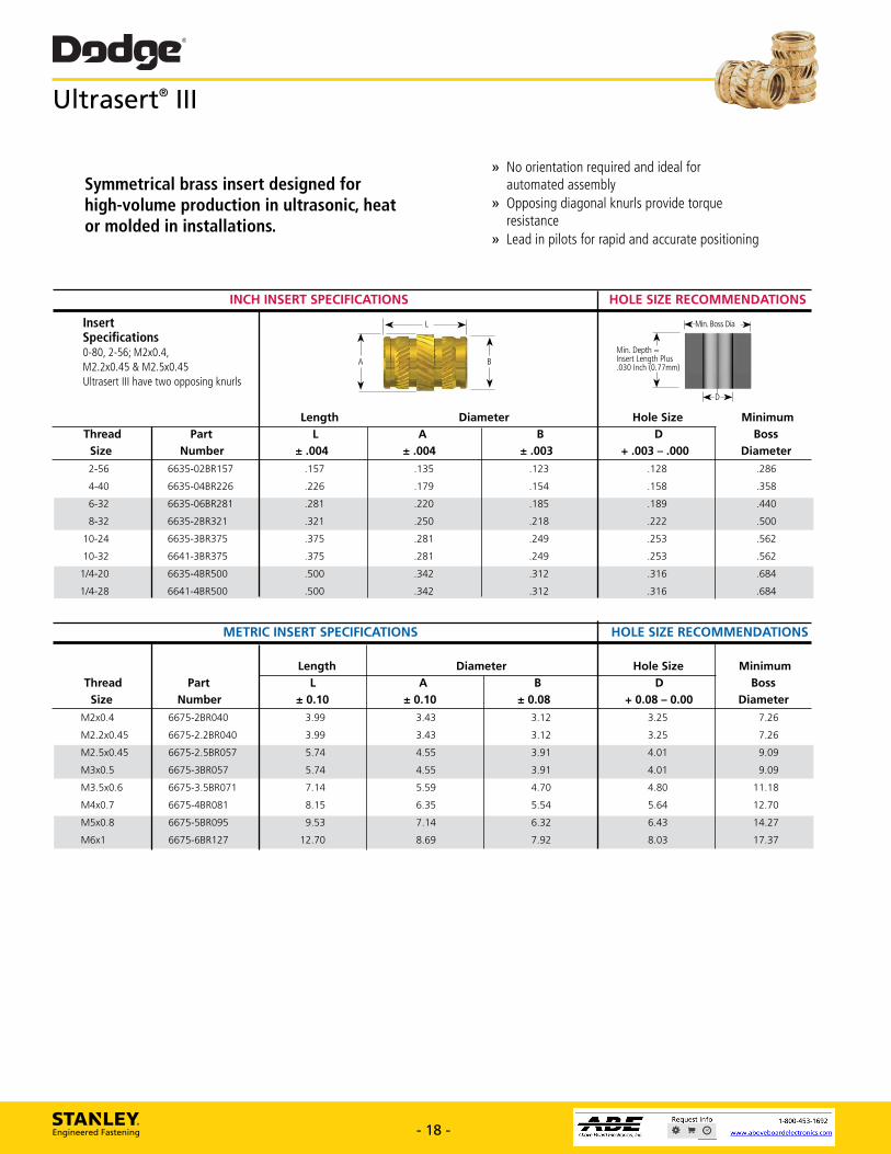
Dodge® Ultraserf III
Symmetrical brass insert designed for high-volume production in ultrasonic, heat or molded in installations.
» No orientation required and ideal for automated assembly
» Opposing diagonal knurls provide torque resistance
» Lead in pilots for rapid and accurate positioning
INCH INSERT SPECIFICATIONS HOLE SIZE RECOMMENDATIONS
*Min. Boss Dia -31e.
Min. Depth Insert Length Plus .030 Inch 0.77mm)
Insert Specifications 0-80, 2-56; M2x0.4, M2.2x0.45 & M2.5x0.45 Ultrasert III have two opposing knurls
Hole Size D
+ .003 - .000 B
± .003 ± .004 A
± .004 Part
Number .123
.154
.135
.179
.157
.226
Thread Size
2-56
4-40
.128
.158
Minimum Boss
Diameter
.286
.358
6635-02BR157
6635-04BR226
METRIC INSERT SPECIFICATIONS HOLE SIZE RECOMMENDATIONS
Length Diameter Hole Size Minimum Thread Part L A B D Boss
Size Number ± 0.10 ± 0.10 ± 0.08 + 0.08 - 0.00 Diameter M2x0.4 6675-2BR040 3.99 3.43 3.12 3.25 7.26
M2.2x0.45 6675-2.2BR040 3.99 3.43 3.12 3.25 7.26
M2.5x0.45 6675-2.5BR057 5.74 4.55 3.91 4.01 9.09
M3x0.5 6675-3BR057 5.74 4.55 3.91 4.01 9.09
M3.5x0.6 6675-3.5BR071 7.14 5.59 4.70 4.80 11.18
M4x0.7 6675-4BR081 8.15 6.35 5.54 5.64 12.70
M5x0.8 6675-5BR095 9.53 7.14 6.32 6.43 14.27
M6x1 6675-6BR127 12.70 8.69 7.92 8.03 17.37
STANLEY. Engineered Fastening - 18 - www.StanleyEngineeredFastening.com - 18 - www.StanleyEngineeredFastening.com
INCH INSERT SPECIFICATIONS HOLE SIZE RECOMMENDATIONS
Length Diameter Hole Size Minimum Thread Part L A B D Boss Size Number ± .004 ± .004 ± .003 + .003 – .000 Diameter 2-56 6635-02BR157 .157 .135 .123 .128 .286
4-40 6635-04BR226 .226 .179 .154 .158 .358
6-32 6635-06BR281 .281 .220 .185 .189 .440
8-32 6635-2BR321 .321 .250 .218 .222 .500
10-24 6635-3BR375 .375 .281 .249 .253 .562
10-32 6641-3BR375 .375 .281 .249 .253 .562
1/4-20 6635-4BR500 .500 .342 .312 .316 .684
1/4-28 6641-4BR500 .500 .342 .312 .316 .684
A
L
Min. Depth = Insert Length Plus .030 Inch (0.77mm)
Min. Boss Dia
D
METRIC INSERT SPECIFICATIONS HOLE SIZE RECOMMENDATIONS
Length Diameter Hole Size Minimum Thread Part L A B D Boss Size Number ± 0.10 ± 0.10 ± 0.08 + 0.08 – 0.00 Diameter
M2x0.4 6675-2BR040 3.99 3.43 3.12 3.25 7.26
M2.2x0.45 6675-2.2BR040 3.99 3.43 3.12 3.25 7.26
M2.5x0.45 6675-2.5BR057 5.74 4.55 3.91 4.01 9.09
M3x0.5 6675-3BR057 5.74 4.55 3.91 4.01 9.09
M3.5x0.6 6675-3.5BR071 7.14 5.59 4.70 4.80 11.18
M4x0.7 6675-4BR081 8.15 6.35 5.54 5.64 12.70
M5x0.8 6675-5BR095 9.53 7.14 6.32 6.43 14.27
M6x1 6675-6BR127 12.70 8.69 7.92 8.03 17.37
InsertSpecifications0-80, 2-56; M2x0.4,M2.2x0.45 & M2.5x0.45Ultrasert III have two opposing knurls
Ultrasert® III
Symmetrical brass insert designed for high-volume production in ultrasonic, heat or molded in installations.
» No orientation required and ideal for automated assembly» Opposing diagonal knurls provide torque resistance» Lead in pilots for rapid and accurate positioning
B
Dodge' Ultrasert® III — Test Data
INCH ABS POLYCARBONATE STRUCTURAL FOAM NYLON 6/6 30% G.F.
Thread Size
Rotation lbs-in.
Tensile lbs
Rotation lbs-in.
Tensile
lbs
Rotation lbs-in.
Tensile lbs
Rotation lbs-in.
Tensile lbs
No. 2
No. 4
r
24*
81
269
r
24t
163
297
r
24*
176
321
8*
24*
166
327
No. 6
No. 8
35
43
288
381
44t
75
548
804
44*
86
518
607
44t
83
606
647
No. 10
1/4"
58
143
494
869
120
239
1006
1666
93
230
719
1240
146
248
654
1362
METRIC ABS POLYCARBONATE STRUCTURAL FOAM NYLON 6/6 30% G.F.
Thread Size
Rotation Nm
Tensile N
Rotation Nm
Tensile N
Rotation Nm
Tensile N
Rotation Nm
Tensile N
M2 & M2.2
M2.5 & M3
0.79*
2.71t
360
1196
0.79t
2.71,
725
1321
0.79*
2.71*
783
1428
0.90*
2.71t
738
1455
M3.5
M4
3.95
4.86
1281
1695
4.97t
8.47
2438
3576
4.97*
9.72
2304
2700
4.97*
9.38
2696
2878
M5
M6
6.55
16.17
2197
3866
13.56
27.00
4475
7411
10.51
25.99
3198
5515
16.50
28.02
2909
6058
(t) Screw failed.
STANLEY. Engineered Fastening - 19 - www.StanleyEngineeredFastening.com - 19 - www.StanleyEngineeredFastening.com
Ultrasert® III – Test Data
INCH ABS POLYCARBONATE STRUCTURAL FOAM NYLON 6/6 30% G.F.
Thread Rotation Tensile Rotation Tensile Rotation Tensile Rotation Tensile
Size lbs-in. lbs lbs-in. lbs lbs-in. lbs lbs-in. lbs
No. 2 7† 81 7† 163 7† 176 8† 166
No. 4 24† 269 24† 297 24† 321 24† 327
No. 6 35 288 44† 548 44† 518 44† 606
No. 8 43 381 75 804 86 607 83 647
No. 10 58 494 120 1006 93 719 146 654
1/4” 143 869 239 1666 230 1240 248 1362
METRIC ABS POLYCARBONATE STRUCTURAL FOAM NYLON 6/6 30% G.F.
Thread Rotation Tensile Rotation Tensile Rotation Tensile Rotation Tensile
Size Nm N Nm N Nm N Nm N M2 & M2.2 0.79† 360 0.79† 725 0.79† 783 0.90† 738
M2.5 & M3 2.71† 1196 2.71† 1321 2.71† 1428 2.71† 1455
M3.5 3.95 1281 4.97† 2438 4.97† 2304 4.97† 2696
M4 4.86 1695 8.47 3576 9.72 2700 9.38 2878
M5 6.55 2197 13.56 4475 10.51 3198 16.50 2909
M6 16.17 3866 27.00 7411 25.99 5515 28.02 6058
(†) Screw failed.
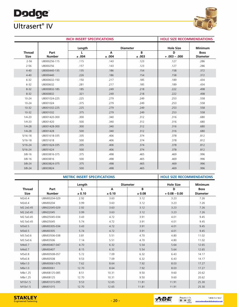
Dodge® Ultrasert® IV
INCH INSERT SPECIFICATIONS HOLE SIZE RECOMMENDATIONS
Thread Size
Part Number
Length Diameter Hole Size Minimum Boss
Diameter L
± .004 A
± .004 B
± .003 D
+ .003 - .000
2-56 UB000256-115 .115 .143 .123 .127 .286
2-56 UB000256 .157 .143 .123 .127 .286
4-40 UB000440-135 .135 .186 .154 .158 .372
4-40 UB000440 .226 .186 .154 .158 .372
6-32 UB000632-150 .150 .217 .185 .189 .434
6-32 UB000632 .281 .217 .185 .189 .434
8-32 UB000832-185 .185 .249 .218 .222 .498
8-32 UB000832 .321 .249 .218 .222 .498
10-24 UB001024-225 .225 .279 .249 .253 .558
10-24 UB001024 .375 .279 .249 .253 .558
10-32 UB001032-225 .225 .279 .249 .253 .558
10-32 UB001032 .375 .279 .249 .253 .558
1/4-20 UB001420-300 .300 .340 .312 .316 .680
1/4-20 UB001420 .500 .340 .312 .316 .680
1/4-28 UB001428-300 .300 .340 .312 .316 .680
1/4-28 UB001428 .500 .340 .312 .316 .680
5/16-18 UB051618-335 .335 .406 .374 .378 .812
5/16-18 UB051618 .500 .406 .374 .378 .812
5/16-24 UB051624-335 .335 .406 .374 .378 .812
5/16-24 UB051624 .500 .406 .374 .378 .812
3/8-16 UB003816-375 .375 .498 .465 .469 .996
3/8-16 UB003816 .500 .498 .465 .469 .996
3/8-24 UB003824-375 .375 .498 .465 .469 .996
3/8-24 UB003824 .500 .498 .465 .469 .996
METRIC INSERT SPECIFICATIONS HOLE SIZE RECOMMENDATIONS
Thread Size
Part Number
Length Diameter Hole Size Minimum Boss
Diameter L
± 0.10 A
± 0.10 B
± 0.08 D
+ 0.08 - 0.00 M2x0.4 UBM00204-029 2.92 3.63 3.12 3.23 7.26
M2x0.4 UBM00204 3.99 3.63 3.12 3.23 7.26
M2.2x0.45 UBM22045-029 2.92 3.63 3.12 3.23 7.26
M2.2x0.45 UBM22045 3.99 3.63 3.12 3.23 7.26
M2.5x0.45 UBM25045-034 3.43 4.72 3.91 4.01 9.45
M2.5x0.45 UBM25045 5.74 4.72 3.91 4.01 9.45
M3x0.5 UBM00305-034 3.43 4.72 3.91 4.01 9.45
M3x0.5 UBM00305 5.74 4.72 3.91 4.01 9.45
M3.5x0.6 UBM03506-038 3.81 5.51 4.70 4.80 11.02
M3.5x0.6 UBM03506 7.14 5.51 4.70 4.80 11.02
M4x0.7 UBM00407-047 4.70 6.32 5.54 5.64 12.65
M4x0.7 UBM00407 8.15 6.32 5.54 5.64 12.65
M5x0.8 UBM00508-057 5.72 7.09 6.32 6.43 14.17
M5x0.8 UBM00508 9.53 7.09 6.32 6.43 14.17
M6x1.0 UBM00061-076 7.62 8.64 7.92 8.03 17.27
M6x1.0 UBM00061 12.70 8.64 7.92 8.03 17.27
M8x1.25 UBM08125-085 8.51 10.31 9.50 9.60 20.62
M8x1.25 UBM08125 12.70 10.31 9.50 9.60 20.62
M10x1.5 UBM01015-095 9.53 12.65 11.81 11.91 25.30
M10x1.5 UBM01015 12.70 12.65 11.81 11.91 25.30
STANLEY. Engineered Fastening - 20 - www.StanleyEngineeredFastening.com - 20 - www.StanleyEngineeredFastening.com
Ultrasert® IV
INCH INSERT SPECIFICATIONS HOLE SIZE RECOMMENDATIONS Length Diameter Hole Size Minimum Thread Part L A B D Boss Size Number ± .004 ± .004 ± .003 + .003 – .000 Diameter 2-56 UB000256-115 .115 .143 .123 .127 .286
2-56 UB000256 .157 .143 .123 .127 .286
4-40 UB000440-135 .135 .186 .154 .158 .372
4-40 UB000440 .226 .186 .154 .158 .372
6-32 UB000632-150 .150 .217 .185 .189 .434
6-32 UB000632 .281 .217 .185 .189 .434
8-32 UB000832-185 .185 .249 .218 .222 .498
8-32 UB000832 .321 .249 .218 .222 .498
10-24 UB001024-225 .225 .279 .249 .253 .558
10-24 UB001024 .375 .279 .249 .253 .558
10-32 UB001032-225 .225 .279 .249 .253 .558
10-32 UB001032 .375 .279 .249 .253 .558
1/4-20 UB001420-300 .300 .340 .312 .316 .680
1/4-20 UB001420 .500 .340 .312 .316 .680
1/4-28 UB001428-300 .300 .340 .312 .316 .680
1/4-28 UB001428 .500 .340 .312 .316 .680
5/16-18 UB051618-335 .335 .406 .374 .378 .812
5/16-18 UB051618 .500 .406 .374 .378 .812
5/16-24 UB051624-335 .335 .406 .374 .378 .812
5/16-24 UB051624 .500 .406 .374 .378 .812
3/8-16 UB003816-375 .375 .498 .465 .469 .996
3/8-16 UB003816 .500 .498 .465 .469 .996
3/8-24 UB003824-375 .375 .498 .465 .469 .996
3/8-24 UB003824 .500 .498 .465 .469 .996
METRIC INSERT SPECIFICATIONS HOLE SIZE RECOMMENDATIONS Length Diameter Hole Size Minimum Thread Part L A B D Boss Size Number ± 0.10 ± 0.10 ± 0.08 + 0.08 – 0.00 Diameter
M2x0.4 UBM00204-029 2.92 3.63 3.12 3.23 7.26
M2x0.4 UBM00204 3.99 3.63 3.12 3.23 7.26
M2.2x0.45 UBM22045-029 2.92 3.63 3.12 3.23 7.26
M2.2x0.45 UBM22045 3.99 3.63 3.12 3.23 7.26
M2.5x0.45 UBM25045-034 3.43 4.72 3.91 4.01 9.45
M2.5x0.45 UBM25045 5.74 4.72 3.91 4.01 9.45
M3x0.5 UBM00305-034 3.43 4.72 3.91 4.01 9.45
M3x0.5 UBM00305 5.74 4.72 3.91 4.01 9.45
M3.5x0.6 UBM03506-038 3.81 5.51 4.70 4.80 11.02
M3.5x0.6 UBM03506 7.14 5.51 4.70 4.80 11.02
M4x0.7 UBM00407-047 4.70 6.32 5.54 5.64 12.65
M4x0.7 UBM00407 8.15 6.32 5.54 5.64 12.65
M5x0.8 UBM00508-057 5.72 7.09 6.32 6.43 14.17
M5x0.8 UBM00508 9.53 7.09 6.32 6.43 14.17
M6x1.0 UBM00061-076 7.62 8.64 7.92 8.03 17.27
M6x1.0 UBM00061 12.70 8.64 7.92 8.03 17.27
M8x1.25 UBM08125-085 8.51 10.31 9.50 9.60 20.62
M8x1.25 UBM08125 12.70 10.31 9.50 9.60 20.62
M10x1.5 UBM01015-095 9.53 12.65 11.81 11.91 25.30
M10x1.5 UBM01015 12.70 12.65 11.81 11.91 25.30
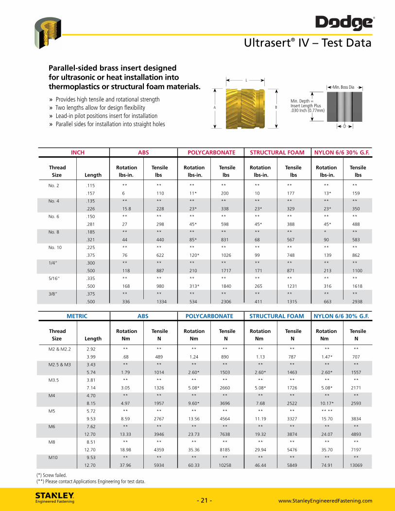
Dodge® Ultrasert® IV - Test Data
Parallel-sided brass insert designed for ultrasonic or heat installation into thermoplastics or structural foam materials.
» Provides high tensile and rotational strength » Two lengths allow for design flexibility » Lead-in pilot positions insert for installation » Parallel sides for installation into straight holes
H
L
-Min. Boss Dia 4.1
Min. Depth = Insert Length Plus .030 Inch (0.77mm)
I I I He
INCH ABS POLYCARBONATE STRUCTURAL FOAM NYLON 6/6 30% G.F.
Thread
Size Length
Rotation
lbs-in.
Tensile
lbs
Rotation
lbs-in.
Tensile
lbs
Rotation
lbs-in.
Tensile
lbs
Rotation
lbs-in.
Tensile
lbs
No. 2 .115 ** ** ** ** ** ** ** **
.157 6 110 11* 200 10 177 13* 159
No. 4 .135 ** ** ** ** ** ** ** **
.226 15.8 228 23* 338 23* 329 23* 350
No. 6 .150 ** ** ** ** ** ** ** **
.281 27 298 45* 598 45* 388 45* 488
No. 8 .185 ** ** ** ** ** ** **
.321 44 440 85* 831 68 567 90 583
No. 10 .225 ** ** ** ** ** ** ** **
.375 76 622 120* 1026 99 748 139 862
1/4" .300 ** ** ** ** ** ** ** **
.500 118 887 210 1717 171 871 213 1100
5/16" .335 ** ** ** ** ** ** ** **
.500 168 980 313* 1840 265 1231 316 1618
3/8" .375 ** ** ** ** ** ** ** **
.500 336 1334 534 2306 411 1315 663 2938
METRIC ABS POLYCARBONATE STRUCTURAL FOAM NYLON 6/6 30% G.F.
Thread
Size Length
Rotation
Nm
Tensile
N
Rotation
Nm
Tensile
N
Rotation
Nm
Tensile
N
Rotation
Nm
Tensile
N
M2 & M2.2 2.92 ** ** ** ** ** ** ** **
3.99 .68 489 1.24 890 1.13 787 1.47* 707
M2.5 & M3 3.43 ** ** ** ** ** ** ** **
5.74 1.79 1014 2.60* 1503 2.60* 1463 2.60* 1557
M3.5 3.81 ** ** ** ** ** ** ** **
7.14 3.05 1326 5.08* 2660 5.08* 1726 5.08* 2171
M4 4.70 ** ** ** ** ** ** ** **
8.15 4.97 1957 9.60* 3696 7.68 2522 10.17* 2593
M5 5.72 ** ** ** ** ** ** ** **
9.53 8.59 2767 13.56 4564 11.19 3327 15.70 3834
M6 7.62 ** ** ** ** ** ** ** **
12.70 13.33 3946 23.73 7638 19.32 3874 24.07 4893
M8 8.51 ** ** ** ** ** ** ** **
12.70 18.98 4359 35.36 8185 29.94 5476 35.70 7197
M10 9.53 ** ** ** ** ** ** ** **
12.70 37.96 5934 60.33 10258 46.44 5849 74.91 13069
(*) Screw failed. (**) Please contact Applications Engineering for test data.
STANLEY. Engineered Fastening - 21 - www.StanleyEngineeredFastening.com - 21 - www.StanleyEngineeredFastening.com
Ultrasert® IV – Test Data
INCH ABS POLYCARBONATE STRUCTURAL FOAM NYLON 6/6 30% G.F.
Thread Rotation Tensile Rotation Tensile Rotation Tensile Rotation Tensile Size Length lbs-in. lbs lbs-in. lbs lbs-in. lbs lbs-in. lbs No. 2 .115 ** ** ** ** ** ** ** **
.157 6 110 11* 200 10 177 13* 159
No. 4 .135 ** ** ** ** ** ** ** **
.226 15.8 228 23* 338 23* 329 23* 350
No. 6 .150 ** ** ** ** ** ** ** **
.281 27 298 45* 598 45* 388 45* 488
No. 8 .185 ** ** ** ** ** ** * **
.321 44 440 85* 831 68 567 90 583
No. 10 .225 ** ** ** ** ** ** ** **
.375 76 622 120* 1026 99 748 139 862
1/4” .300 ** ** ** ** ** ** ** **
.500 118 887 210 1717 171 871 213 1100
5/16” .335 ** ** ** ** ** ** ** **
.500 168 980 313* 1840 265 1231 316 1618
3/8” .375 ** ** ** ** ** ** ** **
.500 336 1334 534 2306 411 1315 663 2938
METRIC ABS POLYCARBONATE STRUCTURAL FOAM NYLON 6/6 30% G.F.
Thread Rotation Tensile Rotation Tensile Rotation Tensile Rotation Tensile Size Length Nm N Nm N Nm N Nm N M2 & M2.2 2.92 ** ** ** ** ** ** ** **
3.99 .68 489 1.24 890 1.13 787 1.47* 707
M2.5 & M3 3.43 ** ** ** ** ** ** ** **
5.74 1.79 1014 2.60* 1503 2.60* 1463 2.60* 1557
M3.5 3.81 ** ** ** ** ** ** ** **
7.14 3.05 1326 5.08* 2660 5.08* 1726 5.08* 2171
M4 4.70 ** ** ** ** ** ** ** **
8.15 4.97 1957 9.60* 3696 7.68 2522 10.17* 2593
M5 5.72 ** ** ** ** ** ** ** **
9.53 8.59 2767 13.56 4564 11.19 3327 15.70 3834
M6 7.62 ** ** ** ** ** ** ** **
12.70 13.33 3946 23.73 7638 19.32 3874 24.07 4893
M8 8.51 ** ** ** ** ** ** ** **
12.70 18.98 4359 35.36 8185 29.94 5476 35.70 7197
M10 9.53 ** ** ** ** ** ** ** **
12.70 37.96 5934 60.33 10258 46.44 5849 74.91 13069
(*) Screw failed. (**) Please contact Applications Engineering for test data.
Parallel-sided brass insert designed for ultrasonic or heat installation into thermoplastics or structural foam materials.
» Provides high tensile and rotational strength» Two lengths allow for design flexibility» Lead-in pilot positions insert for installation » Parallel sides for installation into straight holes
A B
Min. Depth = Insert Length Plus .030 Inch (0.77mm)
Min. Boss Dia
D
L

Hole Diameter
Flange Thickness
MM. Insert .030
Hole Size
Min. Boss Dia 41 Hor-
Depth = Length Plus
Inch (0.77mm)
Minimum Boss
Diameter
Counterbore Diameter Depth
A ± .005
B
± .003 C
± .003 D
+ .003 - .000 E
± .001 F
± .001 .188
.188
.123
.123
.018
.018
.127
.127
.204
.204
.022
.022
.286
.286
.219 .154 .021 .158 .235 .025 .372
.219 .154 .021 .158 .235 .025 .372
.250 .185 .027 .189 .266 .031 .434
.250 .185 .027 .189 .266 .031 .434
.281 .218 .033 .222 .297 .037 .498
.281 .218 .033 .222 .297 .037 .498
.313 .249 .040 .253 .329 .040 .558
.313 .249 .040 .253 .329 .044 .558
.313 .249 .040 .253 .329 .044 .558
.313 .249 .040 .253 .329 .044 .558
.375 .312 .050 .316 .391 .054 .680
.375 .312 .050 .316 .391 .054 .680
.375 .312 .050 .316 .391 .054 .680
.375 .312 .050 .316 .391 .054 .680
.438 .374 .050 .378 .454 .054 .812
.438 .374 .050 .378 .454 .054 .812
.438 .374 .050 .378 .454 .054 .812
.438 .374 .050 .378 .454 .054 .812
.550 .465 .065 .469 .566 .069 .996
.550 .465 .065 .469 .566 .069 .996
.550 .465 .065 .469 .566 .069 .996
.550 .465 .065 .469 .566 .069 .996
Thread Size
Part Number
2-56
2-56
UFB000256-133
UFB000256
4-40 UFB000440-156
4-40 UFB000440
6-32 UFB000632-177
6-32 UFB000632
8-32 UFB000832-218
8-32 UFB000832
10-24 UFB001024-265
10-24 UFB001024
10-32 UFB001032-265
10-32 UFB001032
1/4-20 UFB001420-350
1/4-20 UFB001420
1/4-28 UFB001428-350
1/4-28 UFB001428
5/16-18 UFB051618-385
5/16-18 UFB051618
5/16-24 UFB051624-385
5/16-24 UFB051624
3/8-16 UFB003816-440
3/8-16 UFB003816
3/8-24 UFB003824-440
3/8-24 UFB003824
Length
± .004 .133
.175
.156
.247
.177
.308
.218
.354
.265
.415
.265
.415
.350
.550
.350
.550
.385
.550
.385
.550
.440
.565
.440
.565
INCH INSERT SPECIFICATIONS
HOLE SIZE RECOMMENDATIONS
Dodge® Ultraserf IV Flanged
METRIC INSERT SPECIFICATIONS HOLE SIZE RECOMMENDATIONS
Thread Size
Part Number
Length Hole Flange
Diameter Thickness Hole Size
Counterbore Minimum
Boss Diameter
Diameter Depth L
± 0.10 A
± 0.13 B
± 0.08 C
± 0.08 D
+ 0.08 - 0.00 E
± 0.03 F
± 0.03 M2x0.4 UFBM00204-034 3.38 4.78 3.12 0.48 3.23 5.18 0.56 7.26
M2x0.4 UFBM00204 4.45 4.78 3.12 0.48 3.23 5.18 0.56 7.26
M2.2x0.45 UFBM22045-034 3.38 4.78 3.12 0.48 3.23 5.18 0.56 7.26
M2.2x0.45 UFBM22045 4.45 4.78 3.12 0.48 3.23 5.18 0.56 7.26
M2.5x0.45 UFBM25045-039 3.96 5.56 3.91 0.53 4.01 5.97 0.64 9.45
M2.5x0.45 UFBM25045 6.27 5.56 3.91 0.53 4.01 5.97 0.64 9.45
M3x0.5 UFBM00305-039 3.96 5.56 3.91 0.53 4.01 5.97 0.64 9.45
M3x0.5 UFBM00305 6.27 5.56 3.91 0.53 4.01 5.97 0.64 9.45
M3.5x0.6 UFBM03506-045 4.50 6.35 4.70 0.69 4.80 6.76 0.79 11.02
M3.5x0.6 UFBM03506 7.82 6.35 4.70 0.69 4.80 6.76 0.79 11.02
M4x0.7 UFBM00407-055 5.54 7.14 5.54 0.84 5.64 7.54 0.94 12.65 M4x0.7 UFBM00407 8.99 7.14 5.54 0.84 5.64 7.54 0.94 12.65
M5x0.8 UFBM00508-067 6.73 7.95 6.32 1.02 6.43 8.36 1.12 14.17
M5x0.8 UFBM00508 10.54 7.95 6.32 1.02 6.43 8.36 1.12 14.17
M6x1.0 UFBM00061-089 8.89 9.53 7.92 1.27 8.03 9.93 1.37 17.27
M6x1.0 UFBM00061 13.97 9.53 7.92 1.27 8.03 9.93 1.37 17.27
M8x1.25 UFBM08125-098 9.78 11.13 9.50 1.27 9.60 11.53 1.37 20.62
M8x1.25 UFBM08125 13.97 11.13 9.50 1.27 9.60 11.53 1.37 20.62
M10x1.5 UFBM01015-111 11.18 13.97 11.81 1.65 11.91 14.38 1.75 25.30
M10x1.5 UFBM01015 14.35 13.97 11.81 1.65 11.91 14.38 1.75 25.30
STANLEY. Engineered Fastening - 22 - www.StanleyEngineeredFastening.com - 22 - www.StanleyEngineeredFastening.com
Ultrasert® IV Flanged INCH INSERT SPECIFICATIONS HOLE SIZE RECOMMENDATIONS
Hole Flange Hole Counterbore Length Diameter Thickness Size Diameter Depth Minimum Thread Part L A B C D E F Boss Size Number ± .004 ± .005 ± .003 ± .003 + .003 - .000 ± .001 ± .001 Diameter 2-56 UFB000256-133 .133 .188 .123 .018 .127 .204 .022 .286
2-56 UFB000256 .175 .188 .123 .018 .127 .204 .022 .286
4-40 UFB000440-156 .156 .219 .154 .021 .158 .235 .025 .372
4-40 UFB000440 .247 .219 .154 .021 .158 .235 .025 .372
6-32 UFB000632-177 .177 .250 .185 .027 .189 .266 .031 .434
6-32 UFB000632 .308 .250 .185 .027 .189 .266 .031 .434
8-32 UFB000832-218 .218 .281 .218 .033 .222 .297 .037 .498
8-32 UFB000832 .354 .281 .218 .033 .222 .297 .037 .498
10-24 UFB001024-265 .265 .313 .249 .040 .253 .329 .040 .558
10-24 UFB001024 .415 .313 .249 .040 .253 .329 .044 .558
10-32 UFB001032-265 .265 .313 .249 .040 .253 .329 .044 .558
10-32 UFB001032 .415 .313 .249 .040 .253 .329 .044 .558
1/4-20 UFB001420-350 .350 .375 .312 .050 .316 .391 .054 .680
1/4-20 UFB001420 .550 .375 .312 .050 .316 .391 .054 .680
1/4-28 UFB001428-350 .350 .375 .312 .050 .316 .391 .054 .680
1/4-28 UFB001428 .550 .375 .312 .050 .316 .391 .054 .680
5/16-18 UFB051618-385 .385 .438 .374 .050 .378 .454 .054 .812
5/16-18 UFB051618 .550 .438 .374 .050 .378 .454 .054 .812
5/16-24 UFB051624-385 .385 .438 .374 .050 .378 .454 .054 .812
5/16-24 UFB051624 .550 .438 .374 .050 .378 .454 .054 .812
3/8-16 UFB003816-440 .440 .550 .465 .065 .469 .566 .069 .996
3/8-16 UFB003816 .565 .550 .465 .065 .469 .566 .069 .996
3/8-24 UFB003824-440 .440 .550 .465 .065 .469 .566 .069 .996
3/8-24 UFB003824 .565 .550 .465 .065 .469 .566 .069 .996
METRIC INSERT SPECIFICATIONS HOLE SIZE RECOMMENDATIONS
Hole Flange Hole Counterbore Length Diameter Thickness Size Diameter Depth Minimum Thread Part L A B C D E F Boss Size Number ± 0.10 ± 0.13 ± 0.08 ± 0.08 + 0.08 - 0.00 ± 0.03 ± 0.03 Diameter M2x0.4 UFBM00204-034 3.38 4.78 3.12 0.48 3.23 5.18 0.56 7.26
M2x0.4 UFBM00204 4.45 4.78 3.12 0.48 3.23 5.18 0.56 7.26
M2.2x0.45 UFBM22045-034 3.38 4.78 3.12 0.48 3.23 5.18 0.56 7.26
M2.2x0.45 UFBM22045 4.45 4.78 3.12 0.48 3.23 5.18 0.56 7.26
M2.5x0.45 UFBM25045-039 3.96 5.56 3.91 0.53 4.01 5.97 0.64 9.45
M2.5x0.45 UFBM25045 6.27 5.56 3.91 0.53 4.01 5.97 0.64 9.45
M3x0.5 UFBM00305-039 3.96 5.56 3.91 0.53 4.01 5.97 0.64 9.45
M3x0.5 UFBM00305 6.27 5.56 3.91 0.53 4.01 5.97 0.64 9.45
M3.5x0.6 UFBM03506-045 4.50 6.35 4.70 0.69 4.80 6.76 0.79 11.02
M3.5x0.6 UFBM03506 7.82 6.35 4.70 0.69 4.80 6.76 0.79 11.02
M4x0.7 UFBM00407-055 5.54 7.14 5.54 0.84 5.64 7.54 0.94 12.65
M4x0.7 UFBM00407 8.99 7.14 5.54 0.84 5.64 7.54 0.94 12.65
M5x0.8 UFBM00508-067 6.73 7.95 6.32 1.02 6.43 8.36 1.12 14.17
M5x0.8 UFBM00508 10.54 7.95 6.32 1.02 6.43 8.36 1.12 14.17
M6x1.0 UFBM00061-089 8.89 9.53 7.92 1.27 8.03 9.93 1.37 17.27
M6x1.0 UFBM00061 13.97 9.53 7.92 1.27 8.03 9.93 1.37 17.27
M8x1.25 UFBM08125-098 9.78 11.13 9.50 1.27 9.60 11.53 1.37 20.62
M8x1.25 UFBM08125 13.97 11.13 9.50 1.27 9.60 11.53 1.37 20.62
M10x1.5 UFBM01015-111 11.18 13.97 11.81 1.65 11.91 14.38 1.75 25.30
M10x1.5 UFBM01015 14.35 13.97 11.81 1.65 11.91 14.38 1.75 25.30
A
L
B
C
Min. Depth = Insert Length Plus .030 Inch (0.77mm)
E
D
Min. Boss Dia
F
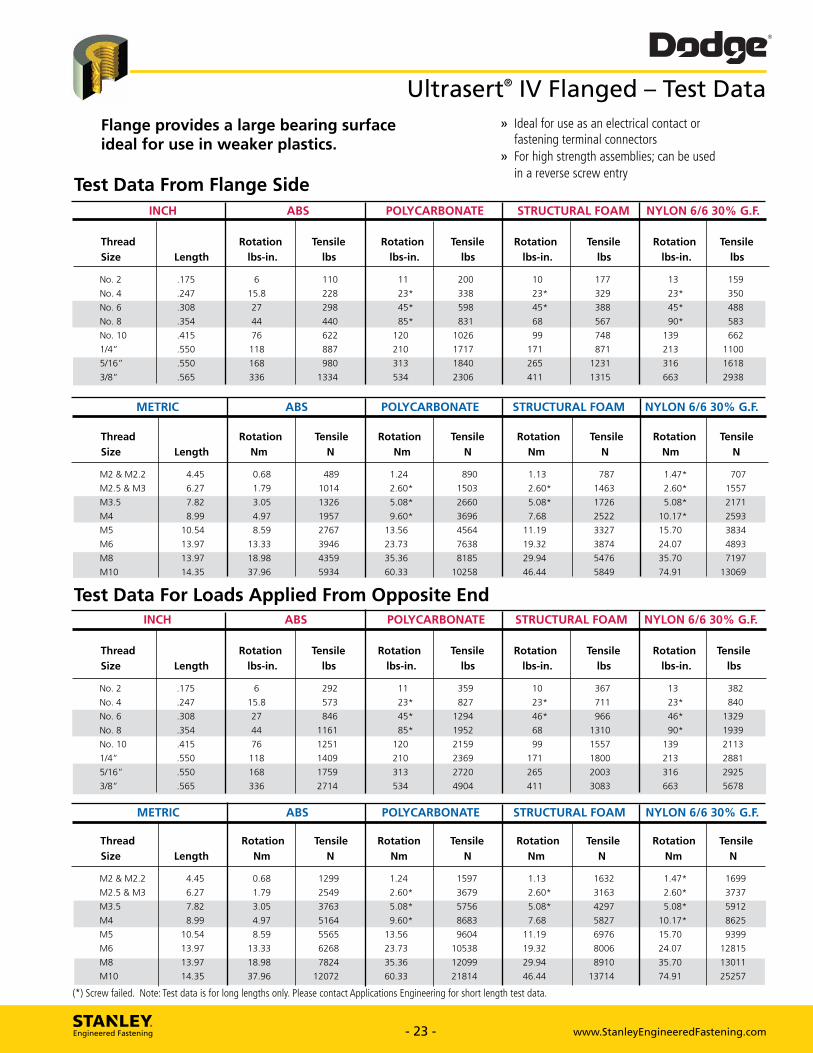
Dodge® Ultrasert® IV Flanged - Test Data
Flange provides a large bearing surface ideal for use in weaker plastics.
Test Data From Flange Side
» Ideal for use as an electrical contact or fastening terminal connectors
» For high strength assemblies; can be used in a reverse screw entry
POLYCARBONATE STRUCTURAL FOAM NYLON 6/6 30% G.F.
Thread Rotation Tensile Rotation Tensile Rotation Tensile Rotation Tensile Size Length lbs-in. lbs lbs-in. lbs lbs-in. lbs lbs-in. lbs
No.2 .175 6 110 11 200 10 177 13 159
No.4 .247 15.8 228 23* 338 23* 329 23* 350
No. 6 .308 27 298 45* 598 45* 388 45* 488
No. 8 .354 44 440 85* 831 68 567 90* 583 No. 10 .415 76 622 120 1026 99 748 139 662
1/4" .550 118 887 210 1717 171 871 213 1100
5/16" .550 168 980 313 1840 265 1231 316 1618
3/8" .565 336 1334 534 2306 411 1315 663 2938
METRIC ABS POLYCARBONATE STRUCTURAL FOAM NYLON 6/6 30% G.F.
Thread Rotation Tensile Rotation Tensile Rotation Tensile Rotation Tensile Size Length Nm N Nm N Nm N Nm N
M2 & M2.2 4.45 0.68 489 1.24 890 1.13 787 1.47* 707
M2.5 & M3 6.27 1.79 1014 2.60* 1503 2.60* 1463 2.60* 1557 M3.5 7.82 3.05 1326 5.08* 2660 5.08* 1726 5.08* 2171
M4 8.99 4.97 1957 9.60* 3696 7.68 2522 10.17* 2593
M5 10.54 8.59 2767 13.56 4564 11.19 3327 15.70 3834
M6 13.97 13.33 3946 23.73 7638 19.32 3874 24.07 4893
M8 13.97 18.98 4359 35.36 8185 29.94 5476 35.70 7197
M10 14.35 37.96 5934 60.33 10258 46.44 5849 74.91 13069
Test Data For Loads Applied From Opposite End INCH POLYCARBONATE STRUCTURAL FOAM NYLON 6/6 30% G.F.
Thread Rotation Tensile Rotation Tensile Rotation Tensile Rotation Tensile Size Length lbs-in. lbs lbs-in. lbs lbs-in. lbs lbs-in. lbs
No.2 .175 6 292 11 359 10 367 13 382
No.4 .247 15.8 573 23* 827 23* 711 23* 840
No. 6 .308 27 846 45* 1294 46* 966 46* 1329
No. 8 .354 44 1161 85* 1952 68 1310 90* 1939 No. 10 .415 76 1251 120 2159 99 1557 139 2113
1/4" .550 118 1409 210 2369 171 1800 213 2881
5/16" .550 168 1759 313 2720 265 2003 316 2925
3/8" .565 336 2714 534 4904 411 3083 663 5678
METRIC ABS POLYCARBONATE STRUCTURAL FOAM NYLON 6/6 30% G.F.
Thread Rotation Tensile Rotation Tensile Rotation Tensile Rotation Tensile Size Length Nm N Nm N Nm N Nm N
M2 & M2.2 4.45 0.68 1299 1.24 1597 1.13 1632 1.47* 1699
M2.5 & M3 6.27 1.79 2549 2.60* 3679 2.60* 3163 2.60* 3737
M3.5 7.82 3.05 3763 5.08* 5756 5.08* 4297 5.08* 5912
M4 8.99 4.97 5164 9.60* 8683 7.68 5827 10.17* 8625
M5 10.54 8.59 5565 13.56 9604 11.19 6976 15.70 9399
M6 13.97 13.33 6268 23.73 10538 19.32 8006 24.07 12815
M8 13.97 18.98 7824 35.36 12099 29.94 8910 35.70 13011
M10 14.35 37.96 12072 60.33 21814 46.44 13714 74.91 25257
(*) Screw failed. Note: Test data is for long lengths only. Please contact Applications Enginee ing for short leng h test data.
STANLEY. Engineered Fastening - 23 - www.StanleyEngineeredFastening.com - 23 - www.StanleyEngineeredFastening.com
Ultrasert® IV Flanged – Test Data
INCH ABS POLYCARBONATE STRUCTURAL FOAM NYLON 6/6 30% G.F.
Thread Rotation Tensile Rotation Tensile Rotation Tensile Rotation Tensile Size Length lbs-in. lbs lbs-in. lbs lbs-in. lbs lbs-in. lbs
No. 2 .175 6 110 11 200 10 177 13 159
No. 4 .247 15.8 228 23* 338 23* 329 23* 350
No. 6 .308 27 298 45* 598 45* 388 45* 488
No. 8 .354 44 440 85* 831 68 567 90* 583
No. 10 .415 76 622 120 1026 99 748 139 662
1/4” .550 118 887 210 1717 171 871 213 1100
5/16” .550 168 980 313 1840 265 1231 316 1618
3/8” .565 336 1334 534 2306 411 1315 663 2938
METRIC ABS POLYCARBONATE STRUCTURAL FOAM NYLON 6/6 30% G.F.
Thread Rotation Tensile Rotation Tensile Rotation Tensile Rotation Tensile Size Length Nm N Nm N Nm N Nm N
M2 & M2.2 4.45 0.68 489 1.24 890 1.13 787 1.47* 707
M2.5 & M3 6.27 1.79 1014 2.60* 1503 2.60* 1463 2.60* 1557
M3.5 7.82 3.05 1326 5.08* 2660 5.08* 1726 5.08* 2171
M4 8.99 4.97 1957 9.60* 3696 7.68 2522 10.17* 2593
M5 10.54 8.59 2767 13.56 4564 11.19 3327 15.70 3834
M6 13.97 13.33 3946 23.73 7638 19.32 3874 24.07 4893
M8 13.97 18.98 4359 35.36 8185 29.94 5476 35.70 7197
M10 14.35 37.96 5934 60.33 10258 46.44 5849 74.91 13069
Test Data From Flange Side
INCH ABS POLYCARBONATE STRUCTURAL FOAM NYLON 6/6 30% G.F.
Thread Rotation Tensile Rotation Tensile Rotation Tensile Rotation Tensile Size Length lbs-in. lbs lbs-in. lbs lbs-in. lbs lbs-in. lbs
No. 2 .175 6 292 11 359 10 367 13 382
No. 4 .247 15.8 573 23* 827 23* 711 23* 840
No. 6 .308 27 846 45* 1294 46* 966 46* 1329
No. 8 .354 44 1161 85* 1952 68 1310 90* 1939
No. 10 .415 76 1251 120 2159 99 1557 139 2113
1/4” .550 118 1409 210 2369 171 1800 213 2881
5/16” .550 168 1759 313 2720 265 2003 316 2925
3/8” .565 336 2714 534 4904 411 3083 663 5678
METRIC ABS POLYCARBONATE STRUCTURAL FOAM NYLON 6/6 30% G.F.
Thread Rotation Tensile Rotation Tensile Rotation Tensile Rotation Tensile Size Length Nm N Nm N Nm N Nm N
M2 & M2.2 4.45 0.68 1299 1.24 1597 1.13 1632 1.47* 1699
M2.5 & M3 6.27 1.79 2549 2.60* 3679 2.60* 3163 2.60* 3737
M3.5 7.82 3.05 3763 5.08* 5756 5.08* 4297 5.08* 5912
M4 8.99 4.97 5164 9.60* 8683 7.68 5827 10.17* 8625
M5 10.54 8.59 5565 13.56 9604 11.19 6976 15.70 9399
M6 13.97 13.33 6268 23.73 10538 19.32 8006 24.07 12815
M8 13.97 18.98 7824 35.36 12099 29.94 8910 35.70 13011
M10 14.35 37.96 12072 60.33 21814 46.44 13714 74.91 25257
Test Data For Loads Applied From Opposite End
Flange provides a large bearing surface ideal for use in weaker plastics.
» Ideal for use as an electrical contact or fastening terminal connectors» For high strength assemblies; can be used in a reverse screw entry
(*) Screw failed. Note: Test data is for long lengths only. Please contact Applications Engineering for short length test data.
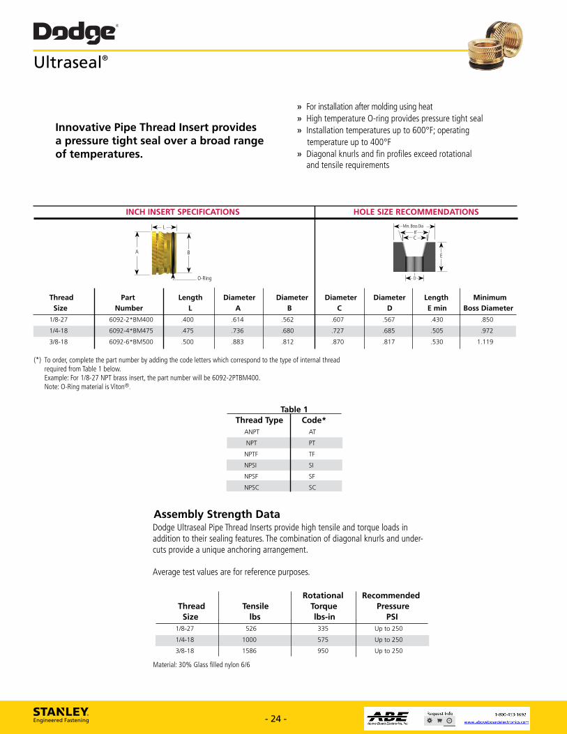
INCH INSERT SPECIFICATIONS
Length
Diameter A
6092-2*BM400 .400
6092-4*BM475 .475
6092-6*BM500 .500
HOLE SIZE RECOMMENDATIONS
Diameter B
Diameter C
Diameter D
Min nos DL3
Minimum
Boss Diameter
Length
E min
.562 .607 .567 .430 .850
.680 .727 .685 .505 .972
.812 .870 .817 .530 1.119
Thread
Size
1/8-27
1/4-18
3/8-18
Part Number
.614
.736
.883
Dodge® Ultraseal®
Innovative Pipe Thread Insert provides a pressure tight seal over a broad range of temperatures.
» For installation after molding using heat » High temperature 0-ring provides pressure tight seal » Installation temperatures up to 600°F; operating
temperature up to 400°F » Diagonal knurls and fin profiles exceed rotational
and tensile requirements
(*) To order, complete the part number by adding the code letters which correspond to the type of internal thread required from Table 1 below. Example: For 1/8-27 NPT brass insert, the part number will be 6092-2PTBM400. Note: 0-Ring material is Viton®.
Table 1
Thread Type Code*
ANPT
NPT
NPTF
NPSI
NPSF
NPSC
AT
PT
TF
SI
SF
SC
Assembly Strength Data Dodge Ultraseal Pipe Thread Inserts provide high tensile and torque loads in addition to their sealing features. The combination of diagonal knurls and under- cuts provide a unique anchoring arrangement.
Average test values are for reference purposes.
Thread Size
Tensile
lbs
Rotational Torque lbs-in
Recommended Pressure
PSI
1/8-27 526 335 Up to 250
1/4-18 1000 575 Up to 250
3/8-18 1586 950 Up to 250
Material: 30% Glass filled nylon 6/6
STANLEY. Engineered Fastening - 24 - www.StanleyEngineeredFastening.com - 24 - www.StanleyEngineeredFastening.com
Ultraseal®
INCH INSERT SPECIFICATIONS HOLE SIZE RECOMMENDATIONS
Thread Part Length Diameter Diameter Diameter Diameter Length Minimum Size Number L A B C D E min Boss Diameter
1/8-27 6092-2*BM400 .400 .614 .562 .607 .567 .430 .850
1/4-18 6092-4*BM475 .475 .736 .680 .727 .685 .505 .972
3/8-18 6092-6*BM500 .500 .883 .812 .870 .817 .530 1.119
O-Ring
A
L
Rotational Recommended Thread Tensile Torque Pressure Size lbs lbs-in PSI 1/8-27 526 335 Up to 250
1/4-18 1000 575 Up to 250
3/8-18 1586 950 Up to 250
Table 1 Thread Type Code* ANPT AT
NPT PT
NPTF TF
NPSI SI
NPSF SF
NPSC SC
C
Min. Boss Dia8˚
D
Innovative Pipe Thread Insert provides a pressure tight seal over a broad range of temperatures.
» For installation after molding using heat» High temperature O-ring provides pressure tight seal » Installation temperatures up to 600°F; operating temperature up to 400°F» Diagonal knurls and fin profiles exceed rotational and tensile requirements
B E
(*) To order, complete the part number by adding the code letters which correspond to the type of internal thread required from Table 1 below. Example: For 1/8-27 NPT brass insert, the part number will be 6092-2PTBM400. Note: O-Ring material is Viton®.
Assembly Strength DataDodge Ultraseal Pipe Thread Inserts provide high tensile and torque loads in addition to their sealing features. The combination of diagonal knurls and under-cuts provide a unique anchoring arrangement. Average test values are for reference purposes.
Material: 30% Glass filled nylon 6/6
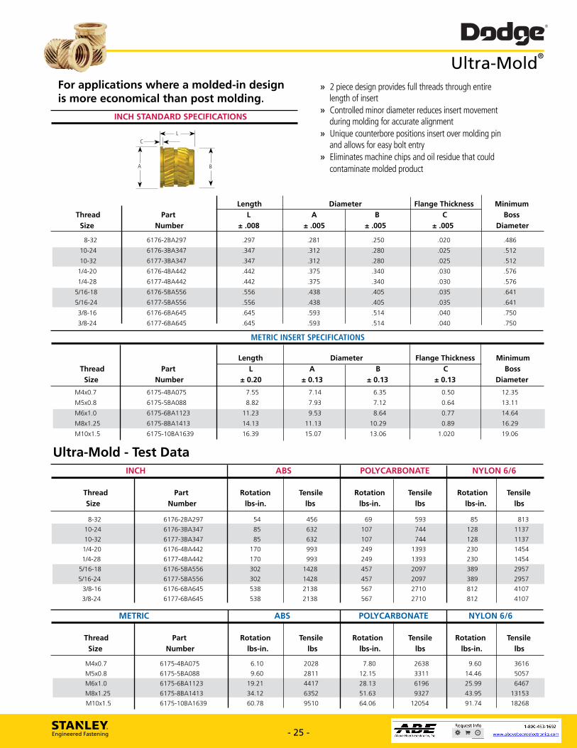
Dodge® Ultra-Mold®
For applications where a molded-in design is more economical than post molding.
2 piece design provides full threads through entire length of insert Controlled minor diameter reduces insert movement during molding for accurate alignment Unique counterbore positions insert over molding pin and allows for easy bolt entry Eliminates machine chips and oil residue that could contaminate molded product
INCH STANDARD SPECIFICATIONS
Thread Size
Part Number
Length Diameter Flange Thickness Minimum Boss
Diameter L
± .008 A
± .005 B
± .005 C
± .005
8-32 6176-2BA297 .297 .281 .250 .020 .486
10-24 6176-3BA347 .347 .312 .280 .025 .512
10-32 6177-3BA347 .347 .312 .280 .025 .512
1/4-20 6176-4BA442 .442 .375 .340 .030 .576
1/4-28 6177-4BA442 .442 .375 .340 .030 .576
5/16-18 6176-5BA556 .556 .438 .405 .035 .641
5/16-24 6177-5BA556 .556 .438 .405 .035 .641
3/8-16 6176-6BA645 .645 .593 .514 .040 .750 7/R-7d. Al 77-ARAAAc AAA cc:P cid run 7cn
METRIC INSERT SPECIFICATIONS
Thread Size
Part Number
Length Diameter Flange Thickness Minimum Boss
Diameter L
± 0.20 A
± 0.13 B
± 0.13 C
± 0.13
M4x0.7 6175-4BA075 7.55 7.14 6.35 0.50 12.35
M5x0.8 6175-5BA088 8.82 7.93 7.12 0.64 13.11
M6x1.0 6175-6BA1123 11.23 9.53 8.64 0.77 14.64
M8x1.25 6175-8BA1413 14.13 11.13 10.29 0.89 16.29
M10x1.5 6175-10BA1639 16.39 15.07 13.06 1.020 19.06
Ultra-Mold - Test Data ABS POLYCARBONATE NYLON 6/6
Thread Part Rotation Tensile Rotation Tensile Rotation Tensile Size Number lbs-in. lbs lbs-in. lbs lbs-in. lbs
8-32 6176-2BA297 54 456 69 593 85 813
10-24 6176-3BA347 85 632 107 744 128 1137
10-32 6177-3BA347 85 632 107 744 128 1137
1/4-20 6176-4BA442 170 993 249 1393 230 1454
1/4-28 6177-4BA442 170 993 249 1393 230 1454
5/16-18 6176-5BA556 302 1428 457 2097 389 2957
5/16-24 6177-5BA556 302 1428 457 2097 389 2957
3/8-16 6176-6BA645 538 2138 567 2710 812 4107
3/8-24 6177-6BA645 538 2138 567 2710 812 4107
METRIC ABS POLYCARBONATE NYLON 6/6
Thread Size
Part Number
Rotation lbs-in.
Tensile lbs
Rotation lbs-in.
Tensile lbs
Rotation lbs-in.
Tensile lbs
M4x0.7
M5x0.8
6175-4BA075
6175-5BA088
6.10
9.60
2028
2811
7.80
12.15
2638
3311
9.60
14.46
3616
5057
M6x1.0
M8x1.25
6175-6BA1123
6175-8BA1413
19.21
34.12
4417
6352
28.13
51.63
6196
9327
25.99
43.95
6467
13153
M10x1.5 6175-10BA1639 60.78 9510 64.06 12054 91.74 18268
STANLEY. Engineered Fastening - 25 - www.StanleyEngineeredFastening.com - 25 - www.StanleyEngineeredFastening.com
For applications where a molded-in design is more economical than post molding.
» 2 piece design provides full threads through entire length of insert» Controlled minor diameter reduces insert movement during molding for accurate alignment» Unique counterbore positions insert over molding pin and allows for easy bolt entry» Eliminates machine chips and oil residue that could contaminate molded product
Ultra-Mold®
INCH STANDARD SPECIFICATIONS
Length Diameter Flange Thickness Minimum Thread Part L A B C Boss Size Number ± .008 ± .005 ± .005 ± .005 Diameter
8-32 6176-2BA297 .297 .281 .250 .020 .486
10-24 6176-3BA347 .347 .312 .280 .025 .512
10-32 6177-3BA347 .347 .312 .280 .025 .512
1/4-20 6176-4BA442 .442 .375 .340 .030 .576
1/4-28 6177-4BA442 .442 .375 .340 .030 .576
5/16-18 6176-5BA556 .556 .438 .405 .035 .641
5/16-24 6177-5BA556 .556 .438 .405 .035 .641
3/8-16 6176-6BA645 .645 .593 .514 .040 .750
3/8-24 6177-6BA645 .645 .593 .514 .040 .750
A
L
B
C
METRIC INSERT SPECIFICATIONS Length Diameter Flange Thickness Minimum Thread Part L A B C Boss Size Number ± 0.20 ± 0.13 ± 0.13 ± 0.13 Diameter
M4x0.7 6175-4BA075 7.55 7.14 6.35 0.50 12.35
M5x0.8 6175-5BA088 8.82 7.93 7.12 0.64 13.11
M6x1.0 6175-6BA1123 11.23 9.53 8.64 0.77 14.64
M8x1.25 6175-8BA1413 14.13 11.13 10.29 0.89 16.29
M10x1.5 6175-10BA1639 16.39 15.07 13.06 1.020 19.06
INCH ABS POLYCARBONATE NYLON 6/6 Thread Part Rotation Tensile Rotation Tensile Rotation Tensile Size Number lbs-in. lbs lbs-in. lbs lbs-in. lbs
8-32 6176-2BA297 54 456 69 593 85 813
10-24 6176-3BA347 85 632 107 744 128 1137
10-32 6177-3BA347 85 632 107 744 128 1137
1/4-20 6176-4BA442 170 993 249 1393 230 1454
1/4-28 6177-4BA442 170 993 249 1393 230 1454
5/16-18 6176-5BA556 302 1428 457 2097 389 2957
5/16-24 6177-5BA556 302 1428 457 2097 389 2957
3/8-16 6176-6BA645 538 2138 567 2710 812 4107
3/8-24 6177-6BA645 538 2138 567 2710 812 4107
Ultra-Mold - Test Data
METRIC ABS POLYCARBONATE NYLON 6/6 Thread Part Rotation Tensile Rotation Tensile Rotation Tensile Size Number lbs-in. lbs lbs-in. lbs lbs-in. lbs
M4x0.7 6175-4BA075 6.10 2028 7.80 2638 9.60 3616
M5x0.8 6175-5BA088 9.60 2811 12.15 3311 14.46 5057
M6x1.0 6175-6BA1123 19.21 4417 28.13 6196 25.99 6467
M8x1.25 6175-8BA1413 34.12 6352 51.63 9327 43.95 13153
M10x1.5 6175-10BA1639 60.78 9510 64.06 12054 91.74 18268
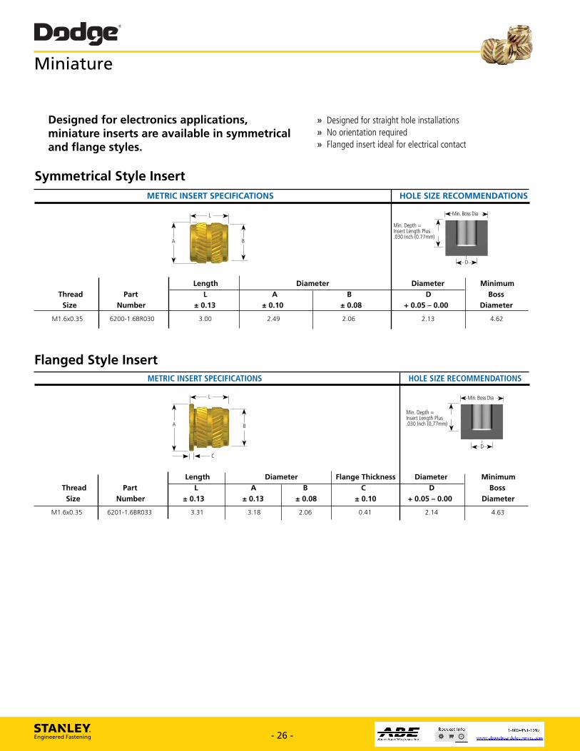
METRIC INSERT SPECIFICATIONS HOLE SIZE RECOMMENDATIONS
Dodge® Miniature
» Designed for straight hole installations » No orientation required » Flanged insert ideal for electrical contact
Designed for electronics applications, miniature inserts are available in symmetrical and flange styles.
Symmetrical Style Insert
STANLEY. Engineered Fastening - 26 - www.StanleyEngineeredFastening.com
Length
Thread Part A
Size Number ± 0.13 ± 0.10
M1.6x0.35 6200-1.688030 3.00 2.49
.-Min. Boss Dia —*I
Min. Depth = Insert Length Plus .030 Inch (0.77mm)
Diameter
2.06
+ 0.05 - 0.00
2.13
Diameter
D
Minimum
Boss
Diameter
4.62
Flanged Style Insert
A
± 0.13
3.18
Thread
Size
M1.6x0.35
—)•fi hic—c
Length
L
± 0.13
3.31
Part
Number
6201-1.688033
HOLE SIZE RECOMMENDATIONS
Diameter Flange Thickness
Min. Depth = Insert Length Plus .030 Inch (0.77mm)
Diameter
hr—Min. Boss Dia
F DPI
Minimum
Boss
Diameter
B
± 0.08
C
± 0.10
D
+ 0.05 - 0.00
2.06 0.41 2.14 4.63
METRIC INSERT SPECIFICATIONS
L
B
± 0.08
- 26 - www.StanleyEngineeredFastening.com
Miniature
METRIC INSERT SPECIFICATIONS HOLE SIZE RECOMMENDATIONS
Length Diameter Diameter Minimum Thread Part L A B D Boss Size Number ± 0.13 ± 0.10 ± 0.08 + 0.05 – 0.00 Diameter
M1.6x0.35 6200-1.6BR030 3.00 2.49 2.06 2.13 4.62
A
L
Min. Depth = Insert Length Plus .030 Inch (0.77mm)
Min. Boss Dia
D
METRIC INSERT SPECIFICATIONS HOLE SIZE RECOMMENDATIONS
Length Diameter Flange Thickness Diameter Minimum Thread Part L A B C D Boss Size Number ± 0.13 ± 0.13 ± 0.08 ± 0.10 + 0.05 – 0.00 Diameter
M1.6x0.35 6201-1.6BR033 3.31 3.18 2.06 0.41 2.14 4.63
C
A
L
Min. Depth = Insert Length Plus .030 Inch (0.77mm)
Min. Boss Dia
D
B
Flanged Style Insert
Designed for electronics applications, miniature inserts are available in symmetrical and flange styles.
» Designed for straight hole installations » No orientation required » Flanged insert ideal for electrical contact
Symmetrical Style Insert
B

Dodge® Expansion - Standard
Simple, press in application Versatile; can be used in all plastics
Expandable two piece inserts for blind holes in thermoset or thermoplastic materials.
INCH INSERT SPECIFICATIONS HOLE SIZE RECOMMENDATIONS
Thread Size
L
Minimum Threaded Length
(-Min. Boss Dia 40.-
Minimum
-h‘411
Body Diameter Diameter* Part
Number
Installed Length Depth
± .004 A
± .003 C
± .001 D
Ref. Boss
Diameter B
4-40 70015-04-250 .250 .156 .178 .158 .250 .312
5-40 70015-05-313 .313 .188 .240 .190 .313 .376
6-32 70015-06-313 .313 .188 .240 .190 .313 .376
6-32 70015-06-375 .375 .188 .303 .190 .375 .376
8-32 70015-2-313 .313 .219 .240 .221 .313 .438
8-32 70015-2-375 .375 .219 .303 .221 .375 .438
10-24 70015-3-375 .375 .250 .303 .252 .375 .500
10-24 70015-3-438 .438 .250 .365 .252 .438 .500
10-32 70011-3-313 .313 .250 .240 .252 .313 .500
10-32 70011-3-375 .375 .250 .303 .252 .375 .500
10-32 70011-3-438 .438 .250 .365 .252 .437 .500
1/4-20 70015-4-500 .500 .313 .428 .315 .500 .626
5/16-18 70015-5-625 .625 .438 .537 .440 .625 .876
METRIC INSERT SPECIFICATIONS HOLE SIZE RECOMMENDATIONS
Installed Length Body Diameter Minimum Diameter* Depth Minimum Thread Part L A Threaded Length C D Boss
Size Number ± 0.10 ± 0.08 B ± 0.03 Ref. Diameter M3x0.5 70017-3-064 6.35 3.97 4.52 4.01 6.40 7.92
M3.5x0.6 70017-3.5-080 7.96 4.78 6.10 4.83 8.00 9.56
M4x0.7 70017-4-080 7.96 5.56 6.10 5.61 8.00 11.13
M4x0.7 70017-4-095 9.53 5.56 7.70 5.61 9.50 11.13
M5x0.8 70017-5-080 8.00 6.35 6.10 6.40 8.00 12.70
M5x0.8 70017-5-095 9.53 6.35 7.70 6.40 9.50 12.70
M6x1 70017-6-127 12.70 7.96 10.87 8.00 12.70 15.90
(*) Diameter "C" is for Thermoset Plastics. For Thermop astic materials, refer to page 29.
Expansion Insert - Test Data** EXPANSION INSERTS ABS POLYCARBONATE PHENOLIC
Inch Size
Metric Size
Insert Length
Rotation lbs-in.
Tensile lbs
Rotation lbs-in.
Tensile lbs
Rotation lbs-in.
Tensile lbs
No. 4 M2.5 .250 13 105 24** 215 24** 171
No. 5
No. 6 M3 & M3.5
.313
.375
21
22
181
173
31
34
239
231
35**
41**
196
199
No. 8
No. 10
M4
M5
.375
.438
44
55
257
342
54
81
317
354
73**
93
318
364
1/4
5/16
M6 .500
.625
88
105
436
606
101
133
465
699
97
110
497
600
(**) To achieve maximum strength, spreader plate must be pushed to the bottom of the hole. See page 29. Note: Test data applies to all types of expansion inserts of comparable length.
STANLEY. Engineered Fastening - 27 - www.StanleyEngineeredFastening.com - 27 - www.StanleyEngineeredFastening.com
METRIC INSERT SPECIFICATIONS HOLE SIZE RECOMMENDATIONS
Installed Length Body Diameter Minimum Diameter* Depth Minimum Thread Part L A Threaded Length C D Boss Size Number ± 0.10 ± 0.08 B ± 0.03 Ref. Diameter M3x0.5 70017-3-064 6.35 3.97 4.52 4.01 6.40 7.92
M3.5x0.6 70017-3.5-080 7.96 4.78 6.10 4.83 8.00 9.56
M4x0.7 70017-4-080 7.96 5.56 6.10 5.61 8.00 11.13
M4x0.7 70017-4-095 9.53 5.56 7.70 5.61 9.50 11.13
M5x0.8 70017-5-080 8.00 6.35 6.10 6.40 8.00 12.70
M5x0.8 70017-5-095 9.53 6.35 7.70 6.40 9.50 12.70
M6x1 70017-6-127 12.70 7.96 10.87 8.00 12.70 15.90
INCH INSERT SPECIFICATIONS HOLE SIZE RECOMMENDATIONS
Installed Length Body Diameter Minimum Diameter* Depth Minimum Thread Part L A Threaded Length C D Boss Size Number ± .004 ± .003 B ± .001 Ref. Diameter 4-40 70015-04-250 .250 .156 .178 .158 .250 .312
5-40 70015-05-313 .313 .188 .240 .190 .313 .376
6-32 70015-06-313 .313 .188 .240 .190 .313 .376
6-32 70015-06-375 .375 .188 .303 .190 .375 .376
8-32 70015-2-313 .313 .219 .240 .221 .313 .438
8-32 70015-2-375 .375 .219 .303 .221 .375 .438
10-24 70015-3-375 .375 .250 .303 .252 .375 .500
10-24 70015-3-438 .438 .250 .365 .252 .438 .500
10-32 70011-3-313 .313 .250 .240 .252 .313 .500
10-32 70011-3-375 .375 .250 .303 .252 .375 .500
10-32 70011-3-438 .438 .250 .365 .252 .437 .500
1/4-20 70015-4-500 .500 .313 .428 .315 .500 .626
5/16-18 70015-5-625 .625 .438 .537 .440 .625 .876
D
Min. Boss Dia
C
A
LB
EXPANSION INSERTS ABS POLYCARBONATE PHENOLIC Inch Metric Insert Rotation Tensile Rotation Tensile Rotation Tensile Size Size Length lbs-in. lbs lbs-in. lbs lbs-in. lbs
No. 4 M2.5 .250 13 105 24** 215 24** 171
No. 5 — .313 21 181 31 239 35** 196
No. 6 M3 & M3.5 .375 22 173 34 231 41** 199
No. 8 M4 .375 44 257 54 317 73** 318
No. 10 M5 .438 55 342 81 354 93 364
1/4 M6 .500 88 436 101 465 97 497
5/16 — .625 105 606 133 699 110 600
Expansion Insert – Test Data**(*) Diameter “C” is for Thermoset Plastics. For Thermoplastic materials, refer to page 29.
Expandable two piece inserts for blind holes in thermoset or thermoplastic materials.
» Simple, press in application » Versatile; can be used in all plastics
(**) To achieve maximum strength, spreader plate must be pushed to the bottom of the hole. See page 29.Note: Test data applies to all types of expansion inserts of comparable length.
Expansion – Standard
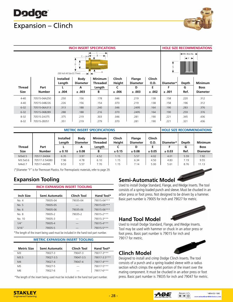
Dodge® Expansion - Clinch
Clinch Model
STANLEY. Engineered Fastening - 28 - www.StanleyEngineeredFastening.com
INCH INSERT SPECIFICATIONS HOLE SIZE RECOMMENDATIONS
Clinch
Height
Flange
Diameter
Clinch
O.D.
Die.Min. Boss
Minimum
Boss
Diameter* Depth
C D E F G
± .006 ± .003 ± .002 ± .001 Ref. Diameter
.046 .219 .138 .158 .220 .312
.070 .219 .138 .158 .196 .312
.046 .2495 .164 .190 .283 .376
.070 .2495 .164 .190 .259 .376
.046 .281 .190 .221 .345 .436
.070 .281 .190 .221 .321 .436
( L B
Thread
Size
Part
Number
.030 Inch All Size
Installed Length
0.77mm)
Body
Diameter
± .004
A
± .003
4-40 70515-04A250 .250 .156
4-40 70515-048226 .226 .156
6-32 70515-06A313 .313 .188
6-32 70515-06B289 .288 .188
8-32 70515-2A375 .375 .219
8-32 70515-2B351 .351 .219
C
D E
Minimum
Threaded
Length
B
.178
.154
.240
.216
.303
.279
METRIC INSERT SPECIFICATIONS HOLE SIZE RECOMMENDATIONS
Thread
Size
Part
Number
Installed
Length
Body
Diameter
Minimum
Threaded
Length
Clinch
Height
Flange
Diameter
Clinch
O.D. Diameter* Depth Minimum
Boss
Diameter
L
± 0.10
A
± 0.08
C
± 0.15
D
± 0.08
E
± 0.05
F
± 0.03
G
Ref. B
M3x0.5 70517-3A064 6.35 3.97 4.52 1.15 5.57 4.02 4.01 5.59 7.92
M3.5x0.6
M4x0.7
70517-3.5A080
70517-4A095
7.96
9.53
4.78
5.57
6.10
7.70
1.15
1.15
6.34
7.14
4.50
5.00
4.83
5.61
7.19
8.76
9.55
11.13
(*)Diameter "F" is for Thermoset Plastics. For Thermoplastic materials, refer to page 29.
Expansion Tooling INCH EXPANSION INSERT TOOLING
Inch Size Semi Automatic Clinch Tool Hand Tool*
No. 4 79005-04 79035-04 79015-04***
No. 5 79005-05 79015-05***
No. 6 79005-06 79035-06 79015-06***
No. 8 79005-2 79035-2 79015-2***
No. 10 79005-3 79015-3***
1/4" 79005-4 79015-4***
5/16" 79005-5 79015-5***
*The length of the insert being used must be included in the hand too part number.
METRIC EXPANSION INSERT TOOLING
Metric Size Semi Automatic Clinch Tool Hand Tool*
M3 79027-3 79047-3 79017-3***
M3.5 79027-3.5 79047-3.5 79017-3.5***
M4 79027-4 79047-4 790174***
M5 79027-5 79017-5***
M6 79027-6 79017-6***
*The length of the insert being used must be included in the hand tool part number.
Semi-Automatic Model Used to install Dodge Standard, Flange, and Wedge Inserts. The tool consists of a spring-loaded punch and sleeve. Must be chucked in an arbor press or foot press. Not designed to be driven by a hammer. Basic part number is 79005 for inch and 79027 for metric.
Hand Tool Model Used to install Dodge Standard, Flange, and Wedge Inserts. Tool may be used with hammer or chuck in an arbor press or foot press. Basic part number is 79015 for inch and 79017 for metric.
Designed to to install and crimp Dodge Clinch Inserts. The tool consists of a punch and a spring-loaded sleeve with a radius section which crimps the eyelet portion of the insert over the mating component. It must be chucked in an arbor press or foot press. Basic part number is 79035 for inch and 79047 for metric.
- 28 - www.StanleyEngineeredFastening.com
Expansion – Clinch
INCH INSERT SPECIFICATIONS HOLE SIZE RECOMMENDATIONS
Installed Body Minimum Clinch Flange Clinch Length Diameter Threaded Height Diameter O.D. Diameter* Depth Minimum Thread Part L A Length C D E F G Boss Size Number ± .004 ± .003 B ± .006 ± .003 ± .002 ± .001 Ref. Diameter
4-40 70515-04A250 .250 .156 .178 .046 .219 .138 .158 .220 .312
4-40 70515-04B226 .226 .156 .154 .070 .219 .138 .158 .196 .312
6-32 70515-06A313 .313 .188 .240 .046 .2495 .164 .190 .283 .376
6-32 70515-06B289 .288 .188 .216 .070 .2495 .164 .190 .259 .376
8-32 70515-2A375 .375 .219 .303 .046 .281 .190 .221 .345 .436
8-32 70515-2B351 .351 .219 .279 .070 .281 .190 .221 .321 .436
METRIC INSERT SPECIFICATIONS HOLE SIZE RECOMMENDATIONS
Installed Body Minimum Clinch Flange Clinch Length Diameter Threaded Height Diameter O.D. Diameter* Depth Minimum Thread Part L A Length C D E F G Boss Size Number ± 0.10 ± 0.08 B ± 0.15 ± 0.08 ± 0.05 ± 0.03 Ref. Diameter
M3x0.5 70517-3A064 6.35 3.97 4.52 1.15 5.57 4.02 4.01 5.59 7.92
M3.5x0.6 70517-3.5A080 7.96 4.78 6.10 1.15 6.34 4.50 4.83 7.19 9.55
M4x0.7 70517-4A095 9.53 5.57 7.70 1.15 7.14 5.00 5.61 8.76 11.13
E
L
A
G
Min. Boss Dia.
F
D
B
.030 Inch All Size (0.77mm)
C
(*)Diameter “F” is for Thermoset Plastics. For Thermoplastic materials, refer to page 29.
INCH EXPANSION INSERT TOOLING
Inch Size Semi Automatic Clinch Tool Hand Tool*
No. 4 79005-04 79035-04 79015-04***
No. 5 79005-05 — 79015-05***
No. 6 79005-06 79035-06 79015-06***
No. 8 79005-2 79035-2 79015-2***
No. 10 79005-3 — 79015-3***
1/4” 79005-4 — 79015-4***
5/16” 79005-5 — 79015-5***
METRIC EXPANSION INSERT TOOLING
Metric Size Semi Automatic Clinch Tool Hand Tool*M3 79027-3 79047-3 79017-3***
M3.5 79027-3.5 79047-3.5 79017-3.5***
M4 79027-4 79047-4 79017-4***
M5 79027-5 — 79017-5***
M6 79027-6 — 79017-6***
Expansion Tooling
*The length of the insert being used must be included in the hand tool part number.
*The length of the insert being used must be included in the hand tool part number.
Semi-Automatic ModelUsed to install Dodge Standard, Flange, and Wedge Inserts. The tool consists of a spring-loaded punch and sleeve. Must be chucked in an arbor press or foot press. Not designed to be driven by a hammer. Basic part number is 79005 for inch and 79027 for metric.
Hand Tool Model Used to install Dodge Standard, Flange, and Wedge Inserts. Tool may be used with hammer or chuck in an arbor press or foot press. Basic part number is 79015 for inch and 79017 for metric.
Clinch Model Designed to install and crimp Dodge Clinch Inserts. The tool consists of a punch and a spring-loaded sleeve with a radius section which crimps the eyelet portion of the insert over the mating component. It must be chucked in an arbor press or foot press. Basic part number is 79035 for inch and 79047 for metric.

L
Flange
EMin. Boss Dia.
EDP
B
Minimum Counterbore
Threaded Diameter Diameter* Depth Diameter Depth Minimum
Length C D E F G Boss
B ± .003 ± .001 Ref. ± .001 ± .001 Diameter
.146 .219 .158 .219 .234 .034 .312
.209 .250 .190 .281 .296 .034 .376
.209 .281 .221 .281 .296 .034 .438
.240 .313 .252 .313 .328 .034 .502
.240 .313 .252 .313 .328 .034 .502
.365 .406 .315 .438 .453 .034 .626
Thread
Size
A
± .003 ± .004
Part
Number
.219 70315-04-219 4-40
10-24
10-32
1/4-20
)11' .030 Inch All Sizes (0.77mm)
Installed Length
Body
Diameter
6-32 70315-06-281 .281
8-32 70315-2-281
70315-3-313
70311-3-313
70315-4-438
.281
.313
.313
.438
.156
.188
.219
.250
.250
.313
Expansion Unset
Expansion Set
Dodge® Expansion - Flanged
INCH INSERT SPECIFICATIONS
HOLE SIZE RECOMMENDATIONS
METRIC INSERT SPECIFICATIONS HOLE SIZE RECOMMENDATIONS
Installed Body Minimum Flange Counterbore
Length Diameter Threaded Diameter Diameter* Depth Diameter Depth Minimum
Thread Part L A Length C D E F G Boss
Size Number ± 0.10 ± 0.08 B ± 0.08 ± 0.03 Ref. ± 0.03 ± 0.03 Diameter
M3x0.5 70317-3-056 5.56 3.96 3.71 5.54 4.01 5.60 5.92 0.86 7.92
M3.5x0.6 70317-3.5-071 7.14 4.78 5.31 6.35 4.83 7.10 6.71 0.86 9.56
M4x0.7 70317-4-071 7.14 5.54 5.31 7.14 5.61 7.10 7.49 0.86 11.13
M5x0.8 70317-5-080 7.95 6.35 6.10 7.93 6.40 8.00 8.31 0.86 12.70
M6x1 70317-6-111 11.13 7.93 9.27 10.32 8.00 11.10 10.67 0.86 15.90
(*)Diameter "D" is for Thermoset Plastics. For Thermoplastic materials, see below.
Expansion Principle These inserts are two piece units consisting of threaded insert and a captivated spreader plate. When this spreader plate is depressed, the knurled portion of the insert expands and anchors the insert in the hole.
Expansion inserts must be expanded by depressing the spreader plate prior to insertion of the screw. The screw will not depress the spreader plate.
The Expansion Inserting Tooling shown on page 28 provides an economical and efficient means of installing the inserts.
The Dodge hand tool works best in thermoset materials. Since the receiving hole diameter is .002 inch larger than the insert diameter, the insert drops freely into the hole and is ready to be expanded using this tool.
Installation Guidelines For thermoplastic materials, the receiving hole diameter is .003 inch (0.076 mm) smaller than the insert diameter.
Because there is interference, the insert must be pressed to the bottom of the hole prior to expanding it. The shoulder on the tool installs the insert. Once it has bottomed, tension on an internal spring is overcome and the punch depresses the spreader plate permanently anchoring the insert in the hole. DO NOT push the spreader plate too deep. This will reduce the holding strength of the insert significantly.
STANLEY. Engineered Fastening - 29 - www.StanleyEngineeredFastening.com - 29 - www.StanleyEngineeredFastening.com
Expansion PrincipleThese inserts are two piece units consisting of threaded insert and a captivated spreader plate. When this spreader plate is depressed, the knurled portion of the insert expands and anchors the insert in the hole.
Expansion inserts must be expanded by depressing the spreader plate prior to insertion of the screw. The screw will not depress the spreader plate.
The Expansion Inserting Tooling shown on page 28 provides an economical and efficient means of installing the inserts.
The Dodge hand tool works best in thermoset materials. Since the receiving hole diameter is .002 inch larger than the insert diameter, the insert drops freely into the hole and is ready to be expanded using this tool.
INCH INSERT SPECIFICATIONS HOLE SIZE RECOMMENDATIONS
Installed Body Minimum Flange Counterbore Length Diameter Threaded Diameter Diameter* Depth Diameter Depth Minimum Thread Part L A Length C D E F G Boss Size Number ± .004 ± .003 B ± .003 ± .001 Ref. ± .001 ± .001 Diameter
4-40 70315-04-219 .219 .156 .146 .219 .158 .219 .234 .034 .312
6-32 70315-06-281 .281 .188 .209 .250 .190 .281 .296 .034 .376
8-32 70315-2-281 .281 .219 .209 .281 .221 .281 .296 .034 .438
10-24 70315-3-313 .313 .250 .240 .313 .252 .313 .328 .034 .502
10-32 70311-3-313 .313 .250 .240 .313 .252 .313 .328 .034 .502
1/4-20 70315-4-438 .438 .313 .365 .406 .315 .438 .453 .034 .626
METRIC INSERT SPECIFICATIONS HOLE SIZE RECOMMENDATIONS
Installed Body Minimum Flange Counterbore Length Diameter Threaded Diameter Diameter* Depth Diameter Depth Minimum Thread Part L A Length C D E F G Boss Size Number ± 0.10 ± 0.08 B ± 0.08 ± 0.03 Ref. ± 0.03 ± 0.03 Diameter
M3x0.5 70317-3-056 5.56 3.96 3.71 5.54 4.01 5.60 5.92 0.86 7.92
M3.5x0.6 70317-3.5-071 7.14 4.78 5.31 6.35 4.83 7.10 6.71 0.86 9.56
M4x0.7 70317-4-071 7.14 5.54 5.31 7.14 5.61 7.10 7.49 0.86 11.13
M5x0.8 70317-5-080 7.95 6.35 6.10 7.93 6.40 8.00 8.31 0.86 12.70
M6x1 70317-6-111 11.13 7.93 9.27 10.32 8.00 11.10 10.67 0.86 15.90
L
A
E
Min. Boss Dia.
D
C
B
.030 Inch All Sizes (0.77mm)
(*)Diameter “D” is for Thermoset Plastics. For Thermoplastic materials, see below.
Expansion – Flanged
Installation Guidelines For thermoplastic materials, the receiving hole diameter is .003 inch (0.076 mm) smaller than the insert diameter.
Because there is interference, the insert must be pressed to the bottom of the hole prior to expanding it. The shoulder on the tool installs the insert. Once it has bottomed, tension on an internal spring is overcome and the punch depresses the spreader plate permanently anchoring the insert in the hole.DO NOT push the spreader plate too deep. This will reduce the holding strength of the insert significantly.
Expansion Set
Expansion Unset
F
G
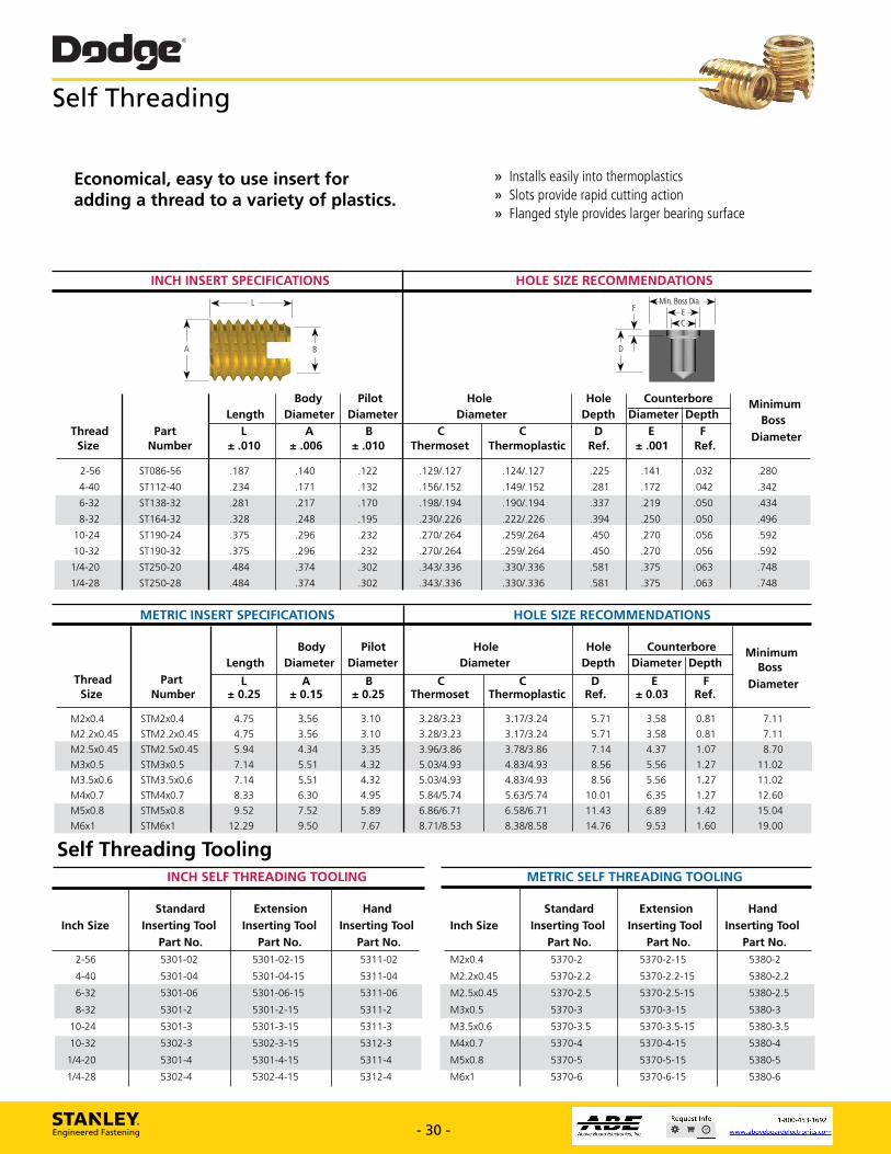
.140
.171
.187
.234
ST086-56
ST112-40
2-56
4-40
L
1 MP Length
Body Diameter
Thread Size
Part Number ± .010
A ± .006
6-32 ST138-32 .281
8-32 ST164-32 .328
10-24 ST190-24 .375
10-32 ST190-32 .375
1/4-20 ST250-20
1/4-28 ST250-28
.484
.484
.217
.248
.296
.296
.374
.374
Dodge® Self Threading
Economical, easy to use insert for adding a thread to a variety of plastics.
» Installs easily into thermoplastics » Slots provide rapid cutting action » Flanged style provides larger bearing surface
INCH INSERT SPECIFICATIONS
HOLE SIZE RECOMMENDATIONS
Pilot Diameter
Hole Diameter
.11CMin. Boss
liEC-*
Dia 41 E 10.
Minimum Boss
Diameter
t
Hole Depth
Counterbore Diameter Depth
B ± .010
C Thermoset
C Thermoplastic
D Ref.
E ± .001
F Ref.
.122
.132
.129/.127
.156/.152
.124/.127
.149/.152
.225
.281
.141
.172
.032
.042
.280
.342
.170 .198/.194 .190/.194 .337 .219 .050 .434
.195 .230/.226 .222/.226 .394 .250 .050 .496
.232 .270/.264 .259/.264 .450 .270 .056 .592
.232 .270/.264 .259/.264 .450 .270 .056 .592
.302 .343/.336 .330/.336 .581 .375 .063 .748
.302 .343/.336 .330/.336 .581 .375 .063 .748
METRIC INSERT SPECIFICATIONS HOLE SIZE RECOMMENDATIONS
Body Pilot Hole Hole Counterbore Minimum Length Diameter Diameter Diameter Depth Diameter Depth Boss
Thread Part L A B C C D E F Diameter Size Number ± 0.25 ± 0.15 ± 0.25 Thermoset Thermoplastic Ref. ± 0.03 Ref.
M2x0.4 STM2x0.4 4.75 3.56 3.10 3.28/3.23 3.17/3.24 5.71 3.58 0.81 7.11
M2.2x0.45 STM2.2x0.45 4.75 3.56 3.10 3.28/3.23 3.17/3.24 5.71 3.58 0.81 7.11
M2.5x0.45 STM2.5x0.45 5.94 4.34 3.35 3.96/3.86 3.78/3.86 7.14 4.37 1.07 8.70
M3x0.5 STM3x0.5 7.14 5.51 4.32 5.03/4.93 4.83/4.93 8.56 5.56 1.27 11.02
M3.5x0.6 STM3.5x0.6 7.14 5.51 4.32 5.03/4.93 4.83/4.93 8.56 5.56 1.27 11.02
M4x0.7 STM4x0.7 8.33 6.30 4.95 5.84/5.74 5.63/5.74 10.01 6.35 1.27 12.60
M5x0.8 STM5x0.8 9.52 7.52 5.89 6.86/6.71 6.58/6.71 11.43 6.89 1.42 15.04
M6x1 STM6x1 12.29 9.50 7.67 8.71/8.53 8.38/8.58 14.76 9.53 1.60 19.00
Self Threading Tooling INCH SELF THREADING TOOLING METRIC SELF THREADING TOOLING
Standard Extension Hand Standard Extension Hand Inch Size Inserting Tool Inserting Tool Inserting Tool Inch Size Inserting Tool Inserting Tool Inserting Tool
Part No. Part No. Part No. Part No. Part No. Part No. 2-56 5301-02 5301-02-15 5311-02 M2x0.4 5370-2 5370-2-15 5380-2
4-40 5301-04 5301-04-15 5311-04 M2.2x0.45 5370-2.2 5370-2.2-15 5380-2.2
6-32 5301-06 5301-06-15 5311-06 M2.5x0.45 5370-2.5 5370-2.5-15 5380-2.5
8-32 5301-2 5301-2-15 5311-2 M3x0.5 5370-3 5370-3-15 5380-3
10-24 5301-3 5301-3-15 5311-3 M3.5x0.6 5370-3.5 5370-3.5-15 5380-3.5
10-32 5302-3 5302-3-15 5312-3 M4x0.7 5370-4 5370-4-15 5380-4
1/4-20 5301-4 5301-4-15 5311-4 M5x0.8 5370-5 5370-5-15 5380-5
1/4-28 5302-4 5302-4-15 5312-4 M6x1 5370-6 5370-6-15 5380-6
STANLEY. Engineered Fastening - 30 - www.StanleyEngineeredFastening.com - 30 - www.StanleyEngineeredFastening.com
Self Threading
INCH INSERT SPECIFICATIONS HOLE SIZE RECOMMENDATIONS
Body Pilot Hole Hole Counterbore Minimum Length Diameter Diameter Diameter Depth Diameter Depth Boss Thread Part L A B C C D E F Diameter Size Number ± .010 ± .006 ± .010 Thermoset Thermoplastic Ref. ± .001 Ref.
2-56 ST086-56 .187 .140 .122 .129/.127 .124/.127 .225 .141 .032 .280
4-40 ST112-40 .234 .171 .132 .156/.152 .149/.152 .281 .172 .042 .342
6-32 ST138-32 .281 .217 .170 .198/.194 .190/.194 .337 .219 .050 .434
8-32 ST164-32 .328 .248 .195 .230/.226 .222/.226 .394 .250 .050 .496
10-24 ST190-24 .375 .296 .232 .270/.264 .259/.264 .450 .270 .056 .592
10-32 ST190-32 .375 .296 .232 .270/.264 .259/.264 .450 .270 .056 .592
1/4-20 ST250-20 .484 .374 .302 .343/.336 .330/.336 .581 .375 .063 .748
1/4-28 ST250-28 .484 .374 .302 .343/.336 .330/.336 .581 .375 .063 .748
METRIC INSERT SPECIFICATIONS HOLE SIZE RECOMMENDATIONS
Body Pilot Hole Hole Counterbore Minimum Length Diameter Diameter Diameter Depth Diameter Depth Boss Thread Part L A B C C D E F Diameter Size Number ± 0.25 ± 0.15 ± 0.25 Thermoset Thermoplastic Ref. ± 0.03 Ref.
M2x0.4 STM2x0.4 4.75 3.56 3.10 3.28/3.23 3.17/3.24 5.71 3.58 0.81 7.11
M2.2x0.45 STM2.2x0.45 4.75 3.56 3.10 3.28/3.23 3.17/3.24 5.71 3.58 0.81 7.11
M2.5x0.45 STM2.5x0.45 5.94 4.34 3.35 3.96/3.86 3.78/3.86 7.14 4.37 1.07 8.70
M3x0.5 STM3x0.5 7.14 5.51 4.32 5.03/4.93 4.83/4.93 8.56 5.56 1.27 11.02
M3.5x0.6 STM3.5x0.6 7.14 5.51 4.32 5.03/4.93 4.83/4.93 8.56 5.56 1.27 11.02
M4x0.7 STM4x0.7 8.33 6.30 4.95 5.84/5.74 5.63/5.74 10.01 6.35 1.27 12.60
M5x0.8 STM5x0.8 9.52 7.52 5.89 6.86/6.71 6.58/6.71 11.43 6.89 1.42 15.04
M6x1 STM6x1 12.29 9.50 7.67 8.71/8.53 8.38/8.58 14.76 9.53 1.60 19.00
A
L
B D
Min. Boss DiaEC
F
INCH SELF THREADING TOOLING
Standard Extension HandInch Size Inserting Tool Inserting Tool Inserting Tool Part No. Part No. Part No. 2-56 5301-02 5301-02-15 5311-02
4-40 5301-04 5301-04-15 5311-04
6-32 5301-06 5301-06-15 5311-06
8-32 5301-2 5301-2-15 5311-2
10-24 5301-3 5301-3-15 5311-3
10-32 5302-3 5302-3-15 5312-3
1/4-20 5301-4 5301-4-15 5311-4
1/4-28 5302-4 5302-4-15 5312-4
METRIC SELF THREADING TOOLING
Standard Extension HandInch Size Inserting Tool Inserting Tool Inserting Tool Part No. Part No. Part No.M2x0.4 5370-2 5370-2-15 5380-2
M2.2x0.45 5370-2.2 5370-2.2-15 5380-2.2
M2.5x0.45 5370-2.5 5370-2.5-15 5380-2.5
M3x0.5 5370-3 5370-3-15 5380-3
M3.5x0.6 5370-3.5 5370-3.5-15 5380-3.5
M4x0.7 5370-4 5370-4-15 5380-4
M5x0.8 5370-5 5370-5-15 5380-5
M6x1 5370-6 5370-6-15 5380-6
Economical, easy to use insert for adding a thread to a variety of plastics.
» Installs easily into thermoplastics » Slots provide rapid cutting action» Flanged style provides larger bearing surface
Self Threading Tooling
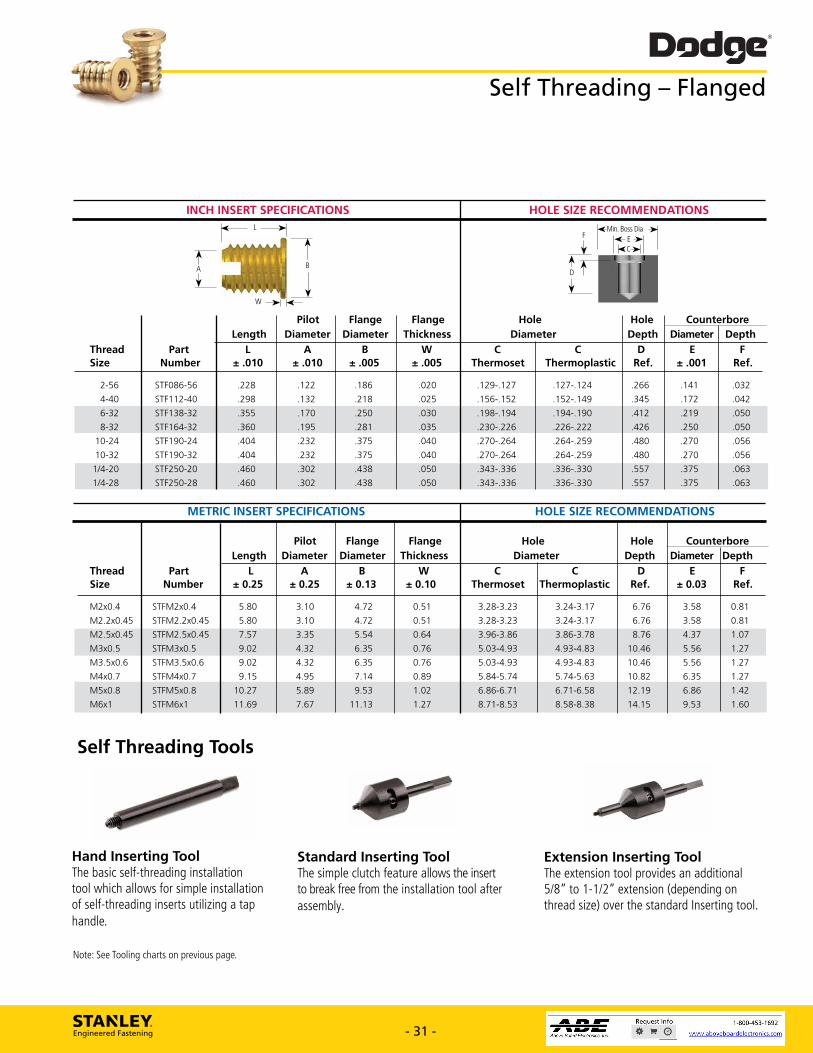
144- E 14(01.1
Min. Boss Dia ->1
.129-.127
.156-.152
.198-.194
.230,226
.270-.264
.270,264
.343-.336
.343-.336
.127-.124
.152-.149
.194-.190
.226-.222
.264-.259
.264-.259
.336-.330
.336-.330
.266
.345
.412
.426
.480
.480
.557
.557
.141
.172
.219
.250
.270
.270
.375
.375
.032
.042
.050
.050
.056
.056
.063
.063
Dodge® Self Threading - Flanged
INCH INSERT SPECIFICATIONS HOLE SIZE RECOMMENDATIONS L
Thread Size
Part Number
Length Length Pilot
Diameter Flange
Diameter Flange
Thickness
± .010 A
± .010 B
± .005 ± .005
2-56 4-40
STF086-56 STF112-40
.228
.298
.122
.132 .186 .218
.020
.025
6-32 STF138-32 .355 .170 .250 .030
8-32 STF164-32 .360 .195 .281 .035
10-24 STF190-24 .404 .232 .375 .040
10-32 STF190-32 .404 .232 .375 .040
1/4-20 STF250-20 .460 .302 .438 .050
1/4-28 STF250-28 .460 .302 .438 .050
C Thermoset
Hole Diameter
C Thermoplastic
Hole Depth
D Ref.
Diameter
± .001
Counterbore Depth
F Ref.
E
L
W
METRIC INSERT SPECIFICATIONS HOLE SIZE RECOMMENDATIONS
Pilot Flange Flange Hole Hole Counterbore Length Diameter Diameter Thickness Diameter Depth Diameter Depth
Thread Part L A B W C C D E F Size Number ± 0.25 ± 0.25 ± 0.13 ± 0.10 Thermoset Thermoplastic Ref. ± 0.03 Ref.
M2x0.4 STFM2x0.4 5.80 3.10 4.72 0.51 3.28-3.23 3.24-3.17 6.76 3.58 0.81
M2.2x0.45 STFM2.2x0.45 5.80 3.10 4.72 0.51 3.28-3.23 3.24-3.17 6.76 3.58 0.81
M2.5x0.45 STFM2.5x0.45 7.57 3.35 5.54 0.64 3.96-3.86 3.86-3.78 8.76 4.37 1.07
M3x0.5 STFM3x0.5 9.02 4.32 6.35 0.76 5.03-4.93 4.93-4.83 10.46 5.56 1.27
M3.5x0.6 STFM3.5x0.6 9.02 4.32 6.35 0.76 5.03-4.93 4.93-4.83 10.46 5.56 1.27
M4x0.7 STFM4x0.7 9.15 4.95 7.14 0.89 5.84-5.74 5.74-5.63 10.82 6.35 1.27
M5x0.8 STFM5x0.8 10.27 5.89 9.53 1.02 6.86-6.71 6.71-6.58 12.19 6.86 1.42
M6x1 STFM6x1 11.69 7.67 11.13 1.27 8.71-8.53 8.58-8.38 14.15 9.53 1.60
Self Threading Tools
Hand Inserting Tool The basic self-threading installation tool which allows for simple installation of self-threading inserts utilizing a tap handle.
Standard Inserting Tool The simple clutch feature allows the insert to break free from the installation tool after assembly.
Extension Inserting Tool The extension tool provides an additional 5/8" to 1-1/2" extension (depending on thread size) over the standard Inserting tool.
Note: See Tooling charts on previous page.
STANLEY. Engineered Fastening - 31 - www.StanleyEngineeredFastening.com - 31 - www.StanleyEngineeredFastening.com
Self Threading – Flanged
INCH INSERT SPECIFICATIONS HOLE SIZE RECOMMENDATIONS
Pilot Flange Flange Hole Hole Counterbore Length Diameter Diameter Thickness Diameter Depth Diameter Depth Thread Part L A B W C C D E F Size Number ± .010 ± .010 ± .005 ± .005 Thermoset Thermoplastic Ref. ± .001 Ref.
2-56 STF086-56 .228 .122 .186 .020 .129-.127 .127-.124 .266 .141 .032
4-40 STF112-40 .298 .132 .218 .025 .156-.152 .152-.149 .345 .172 .042
6-32 STF138-32 .355 .170 .250 .030 .198-.194 .194-.190 .412 .219 .050
8-32 STF164-32 .360 .195 .281 .035 .230-.226 .226-.222 .426 .250 .050
10-24 STF190-24 .404 .232 .375 .040 .270-.264 .264-.259 .480 .270 .056
10-32 STF190-32 .404 .232 .375 .040 .270-.264 .264-.259 .480 .270 .056
1/4-20 STF250-20 .460 .302 .438 .050 .343-.336 .336-.330 .557 .375 .063
1/4-28 STF250-28 .460 .302 .438 .050 .343-.336 .336-.330 .557 .375 .063
METRIC INSERT SPECIFICATIONS HOLE SIZE RECOMMENDATIONS
Pilot Flange Flange Hole Hole Counterbore Length Diameter Diameter Thickness Diameter Depth Diameter Depth Thread Part L A B W C C D E F Size Number ± 0.25 ± 0.25 ± 0.13 ± 0.10 Thermoset Thermoplastic Ref. ± 0.03 Ref.
M2x0.4 STFM2x0.4 5.80 3.10 4.72 0.51 3.28-3.23 3.24-3.17 6.76 3.58 0.81
M2.2x0.45 STFM2.2x0.45 5.80 3.10 4.72 0.51 3.28-3.23 3.24-3.17 6.76 3.58 0.81
M2.5x0.45 STFM2.5x0.45 7.57 3.35 5.54 0.64 3.96-3.86 3.86-3.78 8.76 4.37 1.07
M3x0.5 STFM3x0.5 9.02 4.32 6.35 0.76 5.03-4.93 4.93-4.83 10.46 5.56 1.27
M3.5x0.6 STFM3.5x0.6 9.02 4.32 6.35 0.76 5.03-4.93 4.93-4.83 10.46 5.56 1.27
M4x0.7 STFM4x0.7 9.15 4.95 7.14 0.89 5.84-5.74 5.74-5.63 10.82 6.35 1.27
M5x0.8 STFM5x0.8 10.27 5.89 9.53 1.02 6.86-6.71 6.71-6.58 12.19 6.86 1.42
M6x1 STFM6x1 11.69 7.67 11.13 1.27 8.71-8.53 8.58-8.38 14.15 9.53 1.60
A
L
BD
Min. Boss DiaEC
F
W
Standard Inserting ToolThe simple clutch feature allows the insert to break free from the installation tool after assembly.
Extension Inserting ToolThe extension tool provides an additional 5/8” to 1-1/2” extension (depending on thread size) over the standard Inserting tool.
Hand Inserting ToolThe basic self-threading installation tool which allows for simple installation of self-threading inserts utilizing a tap handle.
Self Threading Tools
Note: See Tooling charts on previous page.
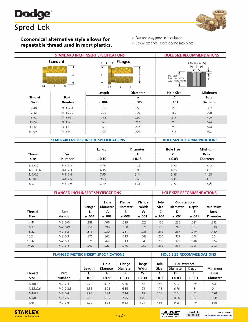
Standard
L
Dodge® Spred-Lok
Economical alternative style allows for repeatable thread used in most plastics.
» Fast and easy press-in installation » Screw expands insert locking into place
HOLE SIZE RECOMMENDATIONS STANDARD INCH INSERT SPECIFICATIONS
Part
Number
Thread
Size
4-40
6-32
w _)H 1,4_ Flanged
Length
± .004
.188
.250
Diameter
A
± .005
.166
.199
Hole Size
Minimum
Boss
Diameter
.156 .332
.188 .398
L ->d
HEMin. Boss Dia -
*-C-*
Min. Depth =
InTlihPu E .OIn (0J7mm)
C
± .001
74115-04
74115-06
8-32
74115-2 .313 .230 .219 .460
10-24
74115-3 .375 .262 .250 .524
10-32
74111-3 .375 .262 .250 .524
1/4-20
74115-4 .500 .326 .313 .652
STANDARD METRIC INSERT SPECIFICATIONS HOLE SIZE RECOMMENDATIONS
Length Diameter Hole Size Minimum
Thread Part L A C Boss
Size Number ± 0.10 ± 0.13 ± 0.03 Diameter
M3x0.5 74117-3 4.78 4.22 3.96 8.43
M3.5x0.6 74117-3.5 6.35 5.05 4.78 10.11
M4x0.7 74117-4 7.95 5.84 5.56 11.68
M5x0.8 74117-5 9.53 6.65 6.35 13.31
M6x1 74117-6 12.70 8.28 7.95 16.56
FLANGED INCH INSERT SPECIFICATIONS HOLE SIZE RECOMMENDATIONS
Hole Flange Flange Hole Counterbore
Length Diameter Diameter Width Size Diameter Depth Minimum
Thread Part L A B W C D E Boss
Size Number ± .004 ± .005 ± .005 ± .004 ± .001 ± .001 ± .001 Diameter
4-40 74215-04 .188 .166 .219 .022 .156 .235 .027 .332
6-32 74215-06 .250 .199 .250 .028 .188 .266 .033 .398
8-32 74215-2 .313 .230 .281 .035 .219 .297 .040 .460
10-24 74215-3 .375 .262 .313 .043 .250 .329 .048 .524
10-32 74211-3 .375 .262 .313 .043 .250 .329 .048 .524
1/4-20 74215-4 .500 .326 .375 .050 .313 .391 .055 .652
FLANGED METRIC INSERT SPECIFICATIONS HOLE SIZE RECOMMENDATIONS
Hole Flange Flange Hole Counterbore
Length Diameter Diameter Width Size Diameter Depth Minimum
Thread Part L A B W C D E Boss
Size Number ± 0.10 ± 0.13 ± 0.13 ± 0.10 ± 0.03 ± 0.03 ± 0.03 Diameter
M3x0.5 74217-3 4.78 4.22 5.56 .56 3.96 5.97 .69 8.43
M3.5x0.6 74217-3.5 6.35 5.05 6.35 .71 4.78 6.76 .84 10.11
M4x0.7 74217-4 7.95 5.84 7.14 .89 5.56 7.54 1.02 11.68
M5x0.8 74217-5 9.53 6.65 7.95 1.09 6.35 8.36 1.22 13.31
M6x1 74217-6 12.70 8.28 9.53 1.27 7.95 9.93 1.40 16.56
STANLEY. Engineered Fastening - 32 - www.StanleyEngineeredFastening.com - 32 - www.StanleyEngineeredFastening.com
Spred–Lok
STANDARD INCH INSERT SPECIFICATIONS HOLE SIZE RECOMMENDATIONS
Length Diameter Hole Size Minimum Thread Part L A C Boss Size Number ± .004 ± .005 ± .001 Diameter 4-40 74115-04 .188 .166 .156 .332
6-32 74115-06 .250 .199 .188 .398
8-32 74115-2 .313 .230 .219 .460
10-24 74115-3 .375 .262 .250 .524
10-32 74111-3 .375 .262 .250 .524
1/4-20 74115-4 .500 .326 .313 .652
AB
L
W
A
L
Standard Flanged
STANDARD METRIC INSERT SPECIFICATIONS HOLE SIZE RECOMMENDATIONS
Length Diameter Hole Size Minimum Thread Part L A C Boss Size Number ± 0.10 ± 0.13 ± 0.03 Diameter
M3x0.5 74117-3 4.78 4.22 3.96 8.43
M3.5x0.6 74117-3.5 6.35 5.05 4.78 10.11
M4x0.7 74117-4 7.95 5.84 5.56 11.68
M5x0.8 74117-5 9.53 6.65 6.35 13.31
M6x1 74117-6 12.70 8.28 7.95 16.56
FLANGED INCH INSERT SPECIFICATIONS HOLE SIZE RECOMMENDATIONS
Hole Flange Flange Hole Counterbore Length Diameter Diameter Width Size Diameter Depth Minimum Thread Part L A B W C D E Boss Size Number ± .004 ± .005 ± .005 ± .004 ± .001 ± .001 ± .001 Diameter 4-40 74215-04 .188 .166 .219 .022 .156 .235 .027 .332
6-32 74215-06 .250 .199 .250 .028 .188 .266 .033 .398
8-32 74215-2 .313 .230 .281 .035 .219 .297 .040 .460
10-24 74215-3 .375 .262 .313 .043 .250 .329 .048 .524
10-32 74211-3 .375 .262 .313 .043 .250 .329 .048 .524
1/4-20 74215-4 .500 .326 .375 .050 .313 .391 .055 .652
FLANGED METRIC INSERT SPECIFICATIONS HOLE SIZE RECOMMENDATIONS
Hole Flange Flange Hole Counterbore Length Diameter Diameter Width Size Diameter Depth Minimum Thread Part L A B W C D E Boss Size Number ± 0.10 ± 0.13 ± 0.13 ± 0.10 ± 0.03 ± 0.03 ± 0.03 Diameter M3x0.5 74217-3 4.78 4.22 5.56 .56 3.96 5.97 .69 8.43
M3.5x0.6 74217-3.5 6.35 5.05 6.35 .71 4.78 6.76 .84 10.11
M4x0.7 74217-4 7.95 5.84 7.14 .89 5.56 7.54 1.02 11.68
M5x0.8 74217-5 9.53 6.65 7.95 1.09 6.35 8.36 1.22 13.31
M6x1 74217-6 12.70 8.28 9.53 1.27 7.95 9.93 1.40 16.56
Economical alternative style allows for repeatable thread used in most plastics.
» Fast and easy press-in installation » Screw expands insert locking into place
Min. Depth = Insert Length Plus .030 Inch (0.77mm)
DC
Min. Boss Dia
E

L- )PH
8° B
Dodge® Tape rTu ff®
Tapered style is ideal for easy installation into thermoplastics.
» Entire length of insert is in contact with hole during installation
» Tapered hole is required and easier to mold » Mold design is simplified and molding costs
decreased
INCH INSERT SPECIFICATIONS HOLE SIZE RECOMMENDATIONS
T
Boss Dia )1i. 8°
C Dia.
Min. Depth = Insert Length Plus .030 Inch (0.77mm)
Straight Knurling Diamond Knurling
Diameter Length Diameters Minimum Boss
Diameter 0.268
0.268
C
+ .002 0.151
0.151
B
± .004 0.144
0.144
A ± .004
.165
.165
± .005 .197
.197
Thread Size
2-56
4-40
Part Number
500256-197
500440-197
6-32
8-32
500632-236
500832-236
0.236
0.236
.220
.235
0.192 0.206
0.201 0.230
0.346
0.385
8-32
10-24
500832-295
501024-275
0.295
0.275
.235
0.281
0.201 0.230
0.242 0.273
0.385
0.429
10-24
10-32
501024-354
501032-275
0.354
0.275
0.281
0.281
0.242 0.273
0.242 0.273
0.429
0.429
10-32
1/4-20
501032-354
501420-354
0.354
0.354
0.281
0.338
0.242 0.273
0.301 0.336
0.429
0.531
1/4-20
1/4-28
501420-393
501420-354
0.393
0.354
0.338
0.338
0.301 0.336
0.301 0.336
0.531
0.531
501420-393
551618-472
551624-472
METRIC INSERT SPECIFICATIONS HOLE SIZE RECOMMENDATIONS
Length Diameters Diameter Minimum Thread Part L A B C Boss
Size Number ± 0.13 ± 0.13 ± 0.10 ± 0.05 Diameter M2x0.4 500204-5 5.00 4.19 3.66 3.85 6.80
M2.5x0.45 525045-5 5.00 4.19 3.66 3.85 6.80
M3x0.5 500305-5 5.00 4.78 4.10 4.45 8.00
M3x0.5 500305-55 5.50 4.78 4.10 4.45 8.00
M3.5x0.6 503506-6 6.00 5.59 4.88 5.25 8.80
M4x0.7 500407-6 6.00 5.97 5.12 5.85 9.80
M4x0.7 500407-75 7.50 5.97 5.12 5.85 9.80
M5x0.8 500508-7 7.00 7.15 6.15 6.95 10.90
M5x0.8 500508-9 9.00 7.15 6.15 6.95 10.90
M6x1 500061-9 9.00 8.60 7.65 8.55 13.50
M6x1 500061-10 10.00 8.60 7.65 8.55 13.50
M8x1.25 508125-12 12.00 11.30 9.60 10.95 16.90
STANLEY. Engineered Fastening - 33 - www.StanleyEngineeredFastening.com
1/4-28
5/16-18
5/16-24
0.393
0.338
0.301
0.336
0.531
0.472
0.444
0.377
0.431
0.665
0.472
0.444
0.377
0.431
0.665
- 33 - www.StanleyEngineeredFastening.com
Tapered style is ideal for easy installation into thermoplastics.
» Entire length of insert is in contact with hole during installation » Tapered hole is required and easier to mold » Mold design is simplified and molding costs decreased
TaperTuff®
INCH INSERT SPECIFICATIONS HOLE SIZE RECOMMENDATIONS
Length Diameters Diameter Minimum Thread Part L A B C Boss Size Number ± .005 ± .004 ± .004 + .002 Diameter 2-56 500256-197 .197 .165 0.144 0.151 0.268
4-40 500440-197 .197 .165 0.144 0.151 0.268
6-32 500632-236 0.236 .220 0.192 0.206 0.346
8-32 500832-236 0.236 .235 0.201 0.230 0.385
8-32 500832-295 0.295 .235 0.201 0.230 0.385
10-24 501024-275 0.275 0.281 0.242 0.273 0.429
10-24 501024-354 0.354 0.281 0.242 0.273 0.429
10-32 501032-275 0.275 0.281 0.242 0.273 0.429
10-32 501032-354 0.354 0.281 0.242 0.273 0.429
1/4-20 501420-354 0.354 0.338 0.301 0.336 0.531
1/4-20 501420-393 0.393 0.338 0.301 0.336 0.531
1/4-28 501420-354 0.354 0.338 0.301 0.336 0.531
1/4-28 501420-393 0.393 0.338 0.301 0.336 0.531
5/16-18 551618-472 0.472 0.444 0.377 0.431 0.665
5/16-24 551624-472 0.472 0.444 0.377 0.431 0.665
Min. Depth = Insert Length Plus .030 Inch (0.77mm)
Min. Boss Dia
Diamond Knurling
A
L
B8˚
Straight Knurling
8˚C Dia.
METRIC INSERT SPECIFICATIONS HOLE SIZE RECOMMENDATIONS
Length Diameters Diameter Minimum Thread Part L A B C Boss Size Number ± 0.13 ± 0.13 ± 0.10 ± 0.05 Diameter M2x0.4 500204-5 5.00 4.19 3.66 3.85 6.80
M2.5x0.45 525045-5 5.00 4.19 3.66 3.85 6.80
M3x0.5 500305-5 5.00 4.78 4.10 4.45 8.00
M3x0.5 500305-55 5.50 4.78 4.10 4.45 8.00
M3.5x0.6 503506-6 6.00 5.59 4.88 5.25 8.80
M4x0.7 500407-6 6.00 5.97 5.12 5.85 9.80
M4x0.7 500407-75 7.50 5.97 5.12 5.85 9.80
M5x0.8 500508-7 7.00 7.15 6.15 6.95 10.90
M5x0.8 500508-9 9.00 7.15 6.15 6.95 10.90
M6x1 500061-9 9.00 8.60 7.65 8.55 13.50
M6x1 500061-10 10.00 8.60 7.65 8.55 13.50
M8x1.25 508125-12 12.00 11.30 9.60 10.95 16.90
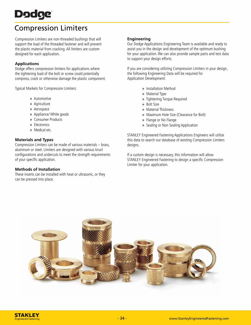
Dodge®
Compression Limiters
Compression Limiters are non-threaded bushings that will support the load of the threaded fastener and will prevent the plastic material from cracking. All limiters are custom designed for each application.
Applications Dodge offers compression limiters for applications where the tightening load of the bolt or screw could potentially compress, crack or otherwise damage the plastic component.
Typical Markets for Compression Limiters:
D Automotive • Agriculture D Aerospace • Appliance/White goods D Consumer Products • Electronics D Medical etc.
Materials and Types Compression Limiters can be made of various materials — brass, aluminum or steel. Limiters are designed with various knurl configurations and undercuts to meet the strength requirements of your specific application.
Methods of Installation These inserts can be installed with heat or ultrasonic, or they can be pressed into place.
Engineering Our Dodge Applications Engineering Team is available and ready to assist you in the design and development of the optimum bushing for your application. We can also provide sample parts and test data to support your design efforts.
If you are considering utilizing Compression Limiters in your design, the following Engineering Data will be required for Application Development:
Installation Method Material Type Tightening Torque Required Bolt Size Material Thickness Maximum Hole Size (Clearance for Bolt) Flange or No Flange Sealing or Non Sealing Application
STANLEY Engineered Fastening Applications Engineers will utilize this data to search our database of existing Compression Limiters designs.
If a custom design is necessary, this information will allow STANLEY Engineered Fastening to design a specific Compression Limiter for your application.
STANLEY. Engineered Fastening - 34 - www.StanleyEngineeredFastening.com - 34 - www.StanleyEngineeredFastening.com
Compression LimitersCompression Limiters are non-threaded bushings that will support the load of the threaded fastener and will prevent the plastic material from cracking. All limiters are custom designed for each application.
ApplicationsDodge offers compression limiters for applications where the tightening load of the bolt or screw could potentially compress, crack or otherwise damage the plastic component.
Typical Markets for Compression Limiters:
» Automotive » Agriculture » Aerospace » Appliance/ White goods » Consumer Products » Electronics » Medical etc.
Materials and TypesCompression Limiters can be made of various materials – brass, aluminum or steel. Limiters are designed with various knurl configurations and undercuts to meet the strength requirements of your specific application.
Methods of InstallationThese inserts can be installed with heat or ultrasonic, or they can be pressed into place.
EngineeringOur Dodge Applications Engineering Team is available and ready to assist you in the design and development of the optimum bushing for your application. We can also provide sample parts and test data to support your design efforts.
If you are considering utilizing Compression Limiters in your design, the following Engineering Data will be required for Application Development:
» Installation Method » Material Type » Tightening Torque Required » Bolt Size » Material Thickness » Maximum Hole Size (Clearance for Bolt) » Flange or No Flange » Sealing or Non Sealing Application
STANLEY Engineered Fastening Applications Engineers will utilize this data to search our database of existing Compression Limiters designs.
If a custom design is necessary, this information will allow STANLEY Engineered Fastening to design a specific Compression Limiter for your application.

Gripco® Gripco® has been providing quality nut and
threaded assembled products since 1904.
CO
f
,)4..ft, Tucker®
. A one-sided drawn-arc welding process
is the foundation of the Tucker No-Hole 7 1 assembly solution.
Warren® Whether it's plastic, metal, or a
combination of the two, Warren can
design a product that will suit your
environment.
Dodge®
Powerful Brands. Breakthrough Solutions.
At STANLEY Engineered Fastening we believe in seeking ways to serve our customers better. We create the future by anticipating our customers needs. Through diversifying our product lines, creating unique assembly technologies and offering a breadth of service to meet the demands of industry worldwide, STANLEY Engineered Fastening provides technological solutions to over 100 different industries.
Avdel® Avdel® has been producing assembly
systems since 1936 and offers a
comprehensive range of fasteners
and tooling.
Dodge® With a focus on high-quality threaded
inserts for plastics products, Dodge has
been a leader in the fastening market
since the 1950s.
Heli-Coil® Based on a long history that began in
the aerospace industry, Heli-Coil offers a
vast range of high-quality.
iForm®
iForm® continues a proud heritage since
1969 and represents over 40 years of
creative threaded fastener application
engineering.
POP® From 2mm micro rivets to 1/4"structural
rivets, POP blind rivets meet the needs of
multiple markets.
STANLEY Assembly Technologies STANLEY Assembly Technologies supplies
production solutions to the global
assembly market.
Spiralock® Spiralock is a technologically superior
fastening system ideally suited for
threaded joint applications subjected to
heavy shock and vibration.
STANLEY. Engineered Fastening - 35 - www.StanleyEngineeredFastening.com - 35 - www.StanleyEngineeredFastening.com
Powerful Brands. Breakthrough Solutions.At STANLEY Engineered Fastening we believe in seeking ways to serve our customers better. We create the future by anticipating our customers needs. Through diversifying our product lines, creating unique assembly technologies and offering a breadth of service to meet the demands of industry worldwide, STANLEY Engineered Fastening provides technological solutions to over 100 different industries.
Avdel®
Avdel® has been producing assembly
systems since 1936 and offers a
comprehensive range of fasteners
and tooling.
Dodge®
With a focus on high-quality threaded
inserts for plastics products, Dodge has
been a leader in the fastening market
since the 1950s.
Gripco®
Gripco® has been providing quality nut and
threaded assembled products since 1904.
Heli-Coil®
Based on a long history that began in
the aerospace industry, Heli-Coil offers a
vast range of high-quality.
iForm®
iForm® continues a proud heritage since
1969 and represents over 40 years of
creative threaded fastener application
engineering.
POP®
From 2mm micro rivets to 1/4"structural
rivets, POP blind rivets meet the needs of
multiple markets.
STANLEY Assembly TechnologiesSTANLEY Assembly Technologies supplies
production solutions to the global
assembly market.
Spiralock®
Spiralock is a technologically superior
fastening system ideally suited for
threaded joint applications subjected to
heavy shock and vibration.
Tucker®
A one-sided drawn-arc welding process
is the foundation of the Tucker No-Hole
assembly solution.
Warren®
Whether it's plastic, metal, or a
combination of the two, Warren can
design a product that will suit your
environment.

STANLEY® Engineered Fastening
,311VIVfr ir -
STANLEY Engineered Fastening, a Stanley Black & Decker Inc. Company has been revolutionizing fastening and assembly technologies for a variety of industries for more than 40 years.
For more information, please visit our website
www.StanleyEngineeredFastening.com
Quick Links:
Our locations http://www.stanleyengineeredfastening.com/contact/global-locations
I Request Information http://www.stanleyengineeredfastening.com/econtact/request-information
I Resource Center http://www.stanleyengineeredfastening.com/resource-center
2015 Stanley Black & Decker, Inc., D4100, Rev. F 12.2015
Dodgee, Ultraserte, Ultraseale, Ultra-Molde and TaperTuffe are registered trademarks of Stanley Black & Decker, Inc. and its affiliates. Vitone is a registered trademark of The Chemours Company FC, LLC.
Data shown is subject to change without prior notice as a result of continuous product development and improvement policy. The information in this catalog is not to be considered a specification. Your local STANLEY Engineered Fastening representative is at your disposal should you need to confirm latest information. HC2000 Rev. 8 (02/12)
STANLEY Engineered Fastening, a Stanley Black & Decker Inc. Company has been revolutionizing fastening and assembly technologies for a variety of industries for more than 40 years.
For more information, please visit our websitewww.StanleyEngineeredFastening.com
Quick Links:
Our locationshttp://www.stanleyengineeredfastening.com/contact/global-locations
Request Informationhttp://www.stanleyengineeredfastening.com/econtact/request-information
Resource Centerhttp://www.stanleyengineeredfastening.com/resource-center
© 2015 Stanley Black & Decker, Inc., D4100, Rev. F 12.2015
Dodge®, Ultrasert®, Ultraseal®, Ultra-Mold® and TaperTuff® are registered trademarks of Stanley Black & Decker, Inc. and its affiliates.Viton® is a registered trademark of The Chemours Company FC, LLC.
Data shown is subject to change without prior notice as a result of continuous product development and improvement policy. The information in this catalog is not to be considered a specification. Your local STANLEY Engineered Fastening representative is at your disposal should you need to confirm latest information.
Top Related