


Languages
Pages
Legal


UCRL-BOOK-207340
Spectroscopy of ions using fastbeams and ion traps
E.H. Pinnington, E. Träbert
October 19, 2004
Handbook of Atomic, Molecular and Optical Physics 2ndedition

Disclaimer
This document was prepared as an account of work sponsored by an agency of the United States Government. Neither the United States Government nor the University of California nor any of their employees, makes any warranty, express or implied, or assumes any legal liability or responsibility for the accuracy, completeness, or usefulness of any information, apparatus, product, or process disclosed, or represents that its use would not infringe privately owned rights. Reference herein to any specific commercial product, process, or service by trade name, trademark, manufacturer, or otherwise, does not necessarily constitute or imply its endorsement, recommendation, or favoring by the United States Government or the University of California. The views and opinions of authors expressed herein do not necessarily state or reflect those of the United States Government or the University of California, and shall not be used for advertising or product endorsement purposes.

Spectroscopy of Ions using Fast Beams and Ion Traps
Eric H. Pinningtony and Elmar Tr�abert#
y Department of Physics, University of Alberta,
Edmonton, Alberta, T6G 2J1 Canada
# Fakult�at f�ur Physik und Astronomie,
Ruhr-Universit�at Bochum, D-44780 Bochum, Germany, and
High Temperature and Astrophysics Division,
Lawrence Livermore National Laboratory, Livermore, CA 94550, U.S.A.
PACS numbers:
1

I. INTRODUCTION
A knowledge of the spectra of ionized atoms is of importance in many �elds (see Sect.
17.1). They can be studied in a wide variety of light sources. In recent years techniques
coming under the broad headings of fast beams and ion traps have been used extensively for
such investigations. This article will consider the advantages that various techniques have
for particular applications.
II. SPECTROSCOPY USING FAST ION BEAMS
A beam of ionized atoms has several advantages as a spectroscopic source. Unlike arcs,
sparks and high temperature plasmas, the ions can be studied in an environment that is
free of electric and magnetic �elds and relatively free of interparticle collisions [1]. Standard
accelerator techniques can be used to produce a well-collimated, mass-analyzed beam of
ions having a low velocity spread. In principle, virtually any charge state of any element,
isotopically pure if required, can be obtained. Finally, the well-de�ned velocity of the ions
permits the study of processes evolving in time in terms of their spatial evolution along the
beam. This is particularly important in the case of lifetime measurements.
A. Beam-Foil Spectroscopy
A beam of ions passing through a thin (50-200 nm) foil emerges in a range of ioniza-
tion states, with the mean charge state increasing with the incident energy [2]. Thin foils
made from a light element, usually carbon, are used to minimize particle scattering and
energy straggling. Thus, a F+ beam of 0.5 MeV that enters a carbon foil emerges from it
with a mean charge of about +2e, while a Xe ion beam at 180MeV emerges with a mean
charge of about +29e. The outer electrons are distributed over many di�erent states, most
of which then decay to lower states by photon emission as the ions move away from the
foil. The beam-foil interaction is highly non-selective, which is an advantage for spectro-
scopic studies but causes a problem for lifetime measurements. (Methods for tackling this
problem are discussed in Sect. 17.3.2.) A major disadvantage of the beam-foil light source
is its low intensity; consequently scanning spectrometers have usually been equipped with
photon-counting detectors. However, in recent years position sensitive detectors have be-
2
come available, which permit the simultaneous recording of information over a wide spectral
range, resulting in a greatly improved detection eÆciency (see Sect. 17.3.4).
The intrinsic properties of the beam-foil interaction are important in understanding its
usefulness for spectroscopic studies. The electrons of the moving ion are shielded from the
travelling ion core as the ion passes through the foil and are then recaptured into a statistical
distribution of outer states. The probability that more than one electron in a given ion will
be captured in an excited state is high relative to other light sources, and hence the technique
has been used extensively to study doubly and multiply excited states [3] (see Sect. 62.1.1?).
The interaction also favours the production of high-L Rydberg states [4] (see Sect. 14.1?).
At low incident ion energies, electron capture can give a downstream beam containing
neutral and even negative ions. The �rst observation of photon emission between bound
states in a negative ion was achieved using beam-foil excitation [5]. A more recent example
of multiple excitation in a negative ion is the identi�cation in lithium-like He� of the 2p3
4So state in which all three electrons are excited [6, 7]. The observation of the same triply
excited level in neutral Li has resulted in one of the most precise (40 ppm) wavelength
measurements in beam-foil spectroscopy [8]. The time-resolution inherent in the beam-foil
source can also be used to aid in the identi�cation of transitions from long-lived states,
such as intercombination transitions [9] (see Sect. 10.17?). Here the beam foil spectrum is
recorded �rst close to the foil and then far downstream (a few mm to a few cm), \far" in this
context meaning that the short-lived states have had time to decay. The intercombination (or
other long-lived) transitions are then easily identi�ed by their relatively strong intensity in
the (overall much weaker) downstream spectrum. This has been a decisive step in identifying
laboratory lines with lines in the solar corona [10, 11]. A recent example of beam-foil
spectroscopic analysis is given in Ref. [12].
One problem with using fast ions as a light source for precision wavelength measurements
is the inevitable Doppler e�ect broadening of the spectral lines. However, this can be
removed by appropriately refocusing the spectrometer [13, 14]. Furthermore, since the
Doppler width varies with the wavelength, and the line width of a given grating spectrometer
used on a fast ion beam usually is dominated by spectrometer geometry, not by di�raction,
Doppler broadening often becomes less important in measurements at shorter wavelengths,
as in the UV or EUV. This is the primary range of emission from the more highly-ionized
atoms, and that is where beam-foil spectroscopy really comes into its own. For example, the
3

leading terms omitted in calculations of the wavelength of the 1s2s 3S - 1s2p 3Po transition in
He-like ions [15] scale as Z4, with the result that measurements made with higher-Z ions need
not have as high a precision for a meaningful test of the calculation as would be required for a
low-Z ion. The beam-foil measurement for the leading (J=1 to J=2) component in Ni26+ [16]
has an uncertainty of 0.02%, which is about equal to that in the calculation. The two values
agree well within this limit. (Naturally, measurements made using the beam-laser techniques
discussed in Sect. 18.2.3 yield results with a much higher precision, but such measurements
are restricted to low-Z ions because of the excitation energy steps and transition wavelengths
involved, and here the theoretical uncertainties are also much smaller.)
Turning now to beam-foil lifetime measurements, here the intensity of a given transition
is studied as a function of the time that has elapsed since excitation, usually by stepping the
foil upstream. Because of the non-selective nature of the excitation, the possibility exists that
the state being studied is itself being repopulated by higher-lying states, resulting in a decay
curve that consists of the sum of exponential terms, one term corresponding to the primary
level being studied and the other terms to higher-lying levels involved in repopulating that
level. The analysis of such decay curves can be problematic. Several computer routines have
been developed to tackle this problem, such as DISCRETE [17] and HOMER [18]. One useful
trick here is to record the decay curve for each of the major transitions repopulating a given
primary level and then include the lifetimes obtained for those transitions as �xed parameters
in �tting the decay curves for that primary level. A more rigorous method to include the
decay data from the repopulating transitions in the analysis of the primary lifetime is the
ANDC technique described in detail in Section 17.3.2. An additional problem may arise in
the measurement of very short lifetimes, which tend to be associated with short-wavelength
transitions for which no lenses are available to focus the beam at the spectrometer entrance
slit. The observation region is then de�ned by the spectrometer aperture and extends for
a �nite length along the beam that can be comparable to, or even greater than, the decay
length for that transition. Here it is necessary to �t the decay curve including the vignetted
region around the foil [19, 20]. Lifetimes in the picosecond regime have been successfully
measured in this way.
4

B. Beam-Gas Spectroscopy
While the use of a gas target in place of a foil has the obvious advantage that it cannot
break, the loss of a tightly-localized excitation region means that the �ne time resolution
of the beam-foil light source is largely lost. The beam-gas source has two main advantages,
however. First, the passage of a beam of fast, highly-stripped ions through a neutral gas
results in the production of recoil ions (see Sect. 63.3?), which are moving very slowly
relative to the beam ions, thus reducing the Doppler broadening problem mentioned earlier.
Secondly, it is possible to study details of the interaction between the gas and beam ions, such
as charge-exchange reactions, as they occur, and not merely observing their consequences.
Such experiments have experienced a resurgence with the advent of the ECR ion source [21].
A recent example of such work is given in Ref. [22].
When a fast beam of highly charged ions passes through a neutral gas, it leaves a trail of
ionized gas atoms in its wake. These ions recoil from the interaction region with relatively
low velocities (v/c = 10�4 - 10�5). Furthermore, the recoil velocities tend to be restricted
to a narrow range of angles approximately perpendicular to the beam direction. Hence,
observation of the radiation emitted by the recoil ions transverse to their motion, i.e. along
a direction parallel to the beam, gives a very low Doppler width, ��D/� being typically 10�6,
the limit imposed by the thermal motion of the target gas atoms. Recoil ion spectroscopy
is therefore a useful procedure for precision wavelength measurements for highly-stripped
ions, such as He-like Ar16+ recoil ions produced by a beam of 2 GeV U70+ ions [23]. The
energies and charge states of the recoil ions may be determined using standard time-of- ight
techniques [24], and detecting the recoil ions in coincidence with their progenitor ions yields
information on the dependence of the recoil energy on the details of the ionizing collision
[25]. In later developments, the di�erentially pumped gas target has �rst been replaced by a
supersonic jet target which reduces the thermal motion of the target particles, and then by
a cold atom sample in an atom trap; replacing optical detection by position-sensitive fast-
timing detectors for all collision products, the technique of COLTRIMS (COLd Target Recoil
Ion Momentum Spectroscopy) now can be employed to study the momentum distribution
of the collision partners [26].
Measurements made on the projectile ions themselves also yield useful information about
electron-capture processes. The strength of such a process is described in terms of its cross
5

section (see Sect. 61.2.2?). Recent work has shifted from measurements of the total cross
section for electron capture, to more detailed studies of the individual capture channels
[27]. Such studies provide much more stringent tests of theoretical models of the ion-atom
charge transfer processes. They often involve such techniques as spectroscopy of the optical
radiation or of the Auger electrons (see Sect. 25.1.1?) emitted by the ions after electron
exchange. A further example is the study by Prior et al [28] of the angular distribution
of Auger electrons emitted by doubly-excited states formed in hydrogen-like projectile ions
with an energy of 40 keV, following double-electron capture from target helium atoms. They
found that signi�cant alignment of the magnetic substates of the projectile ions can result
from electron capture. Such anisotropies in the Auger electron emission demonstrate the
danger of using single-angle measurements to determine cross sections.
C. Beam-Laser Spectroscopy
As for the beam-foil source, excitation of a beam of fast ions by a transverse tuneable
laser produces the localized excitation required for high temporal resolution. Now, however,
the excitation is highly selective, permitting the population of just a single level. The
laser-induced- uorescence (LIF) signal as a function of the distance along the beam from
the excitation region is therefore described by a single exponential decay, for which an exact
analysis with rigorous error bounds is possible. The restriction to levels that can be accessed
by electric dipole (E1) transitions from the ground and metastable levels may be overcome
by combining laser excitation with a non-selective mode of excitation, as in beam-gas-laser
[29] or beam-foil-laser [30] measurements. A discussion of precision lifetime measurements
using laser excitation of a fast beam is given in Sect. 17.3.2. Here the discussion will
be limited to precision optical spectroscopy. Examples of precision beam-laser wavelength
measurements may be found in Refs. [31] and [32]. A further example is the measurement
of the spin-forbidden 1s2s 1S0 - 1s2p 3P1 interval in N5+ [33], where the experimental value,
986.321(7) cm�1 is in agreement with the calculated value, 986.58(30) cm�1. An example
of a similar measurement in a molecular ion is given in [34], while a recent study of the
hyper�ne structure in a rare-earth ion is given in Ref. [35].
A major aim in beam-laser spectroscopy is to minimize the width of the LIF signal.
The instrumental linewidth of the laser itself can be reduced to below 1 kHz, so that the
6
width of the LIF signal is usually dominated by the velocity spread of the ions and by the
divergences of the ion and laser beams. The e�ects of beam divergence can be minimized
by using the collinear geometry, in which the ion and laser beams are parallel. If the angle
between the ion and laser beams is �, the Doppler-shifted laser frequency, as measured in
the ion's rest frame, is fL(1-� cos �), where is fL is the laser frequency and � = v/c and is
much less than unity. Hence the range in frequency resulting from a beam divergence, ��,
is given by fL � sin ���, which tends to zero as � tends to zero. One disadvantage of the
collinear geometry is that, if the laser is brought into resonance with an atomic transition
by adjusting the ion velocity and/or the laser frequency, the LIF signal is produced over the
entire overlap region between the ion and laser beams. The resonance can be restricted to a
desired region by setting the ion velocity to be slightly o�-resonance. The velocity can then
be adjusted locally for resonance with the laser by passing the ion beam through a Faraday
cage electrode to which an adjustable voltage is applied [36, 37]. The width of the resonance
signal here is usually dominated by the spread in the ion velocity, c ���, usually arising in
the ion source being used. The width resulting from a given �� can therefore be reduced
by using a higher ion energy. This is known as kinematic compression. In terms of the ion
energy E, the range in the ion energy �E and the ion mass M, the Doppler width of the
LIF signal is given by fL �E/(2Mc2E)1=2 and thus decreases as E is increased.
A more signi�cant improvement in frequency resolution is made possible by including rf
resonance in a laser double-resonance experiment. Here the ions are brought into resonance
with an o�-resonance laser using two separate Faraday cage electrodes. The �rst resonance
depletes the population in the ion state from which excitation occurs, thus weakening the
second resonance signal. An rf �eld is then applied to the ions between the two electrodes.
Tuning the frequency of this �eld over the region that corresponds to �ne- or hyper�ne-
structure intervals in the ion can then repopulate the state from which laser excitation occurs,
thus re-establishing the second laser LIF resonance signal. The width of the resonance signal
is now determined by the transit-time broadening that results from the �nite time spent by
the ions in the rf �eld (see also Sect. 74.6.1?). For example, in the experiments by Sen et
al [37] with a beam of 131Eu+ ions at 1.35 keV, the width of the laser-rf double-resonance
signal was 59 kHz, compared with a width of 45 MHz obtained using a single LIF resonance.
7

D. Other techniques of ion-beam spectroscopy
Ion beams �nd uses in many other applications, three of the main areas involving storage
rings (discussed in Sect. 18.3.2), merged beams and studies of the ion-surface interaction
at grazing incidence. Merged beam experiments usually study recombination processes
involving electrons and atomic or molecular ions (see Sect. 52.1? regarding recombination
processes). The advantage of using merged beams is that the time development of the
processes may be studied spatially, while maintaining a low relative velocity between the
ions and the electrons. This permits measurements at the low energies of importance in
studies of Rydberg state formation and in some astrophysical applications. A very di�erent
type of experiment studies the ion-surface interaction using a well-collimated ion beam at
grazing incidence on a clean, at surface. Such experiments have revealed very large atomic
orientations [38]. This orientation can be passed on to the nuclei of the atoms via the
hyper�ne interaction, thus providing a source of oriented nuclei.
III. SPECTROSCOPY USING ION TRAPS
A basic purpose of ion traps is to con�ne ions to the �eld of view of detectors for time
intervals that are longer than the radiative lifetimes of long-lived atomic levels of possible
interest. At thermal energies, the ion velocities are large enough to leave a typical detection
zone within microseconds. Electrostatic (Kingdon), magnetic (Penning), and radiofrequency
(Paul) traps have served for this task for decades (see chapter 73), with recent additions
to the armory by electrostatic mirrors of various shapes [39, 40]. Two trap varieties of
particular interest for spectroscopy, the electron beam ion trap and the heavy-ion storage
ring, will be treated in special sections below.
Collisions with the neutral atoms and molecules of the residual gas cause charge exchange
and thus loss of the ion species. Therefore ultrahigh vacuum is of primary importance. Over
the last three decades the �gure of merit has moved from pressures of about 10�8 mbar to
about 10�11 mbar. Further improvements can be expected from working with traps at liquid
helium temperature; in fact, even ion traps as large as an ion storage ring at Aarhus (see
the section below) have been cooled considerably to vary both the vacuum and the amount
of blackbody radiation experienced by ions in weakly bound states.
8

The energy steps in multiply charged ions are regularly larger than what is available from
lasers, at least for excitation from the ground state. Hence single-ion trapping and laser
spectroscopic investigation are rarely an option for these ions. Many ions are then needed
to provide a suÆciently strong emission signal. The production of quantities of multiply
charged ions used to be achieved by electron bombardment of a dilute gas inside the trap
volume, or by ablation from a surface. Evidently, this is detrimental to any subsequent
measurements, since the residual gas is still present. Precision work like mass spectrometry
that exploits the ion cyclotron motion of stored ions, or detailed studies of the radiative
processes (including the e�ects of the interrogating laser �eld) in ions nowadays employ a
sequence of ion traps. In a �rst trap, the ions of interest are produced and possibly cooled
by laser light or other mechanisms, and then, by applying electric �elds, the ions of interest
are moved to a second trap that works under better vacuum conditions or that can be more
�nely tuned. In the same sense, a heavy ion storage ring is being fed by an isotopically
pure, charge-state selected ion beam. Any loss of ions measured by whatever means thus is
proportional to the loss of the ion species of interest.
A. Electron beam ion traps
Electron beam ion traps (EBIT) make use of the attractive potential of a high-density
electron beam as well as of the space charge compensation that is provided by the electron
beam to any ion cloud already trapped. Most electron beam ion traps generate the high-
current density electron beam by feeding the beam from an electron gun into a magnetic �eld
that then compresses and guides the beam. In most cases, superconducting magnets with
�elds of 3 to 8 T are being used, and current densities of the order of 104 A/mm2 are reached.
This high current density corresponds to an electron density of the order of 1011/cm3. This
low-density environment, roughly comparable to tokamak discharges, is one of the factors
that renders the electron beam ion trap a very interesting device for laboratory astrophysics.
The magnetic �eld helps to con�ne any ion cloud that is produced from the residual gas (or
gas bled in) or from injected low charge ions. However, the ions could move away along the
�eld lines, if they were not stopped by potential barriers provided by electrically charged
drift tubes. Obviously, the basic design is the same as that of a Penning trap, with the
permanent electron beam added. In fact, EBIT with the electron beam on has been called
9

to operate in electronic trapping mode [41]; while the same device with the electron beam o�
(\magnetic trapping mode") still works as a Penning trap. This option of producing an ion
cloud with intense electron bombardment and then studying the ions without the electron
beam present is the basis for a variety of experiments on charge exchange (CX) reactions
and long-lived excited levels [42] (see below).
The �rst working electron beam ion trap, EBIT-I, has been set up at Livermore [43, 44].
The successful operation instigated an upgrade to SuperEBIT, the �rst such machine that
was able to completely ionize all naturally occurring elements [45]. Mostly based on the
Livermore design, some 8 to 10 EBITs are by now either running or under construction
around the world. The EBIT operating principles have, for example, been described by
Currell [46].
Ionization of ions trapped in the combination of electrical �elds proceeds as long as the
electron beam energy is high enough to overcome the ionization potential. Thus the highest
charge state can be pre-selected by the appropriate choice of the electron beam energy. The
technical e�ort to reach, for example, bare uranium in SuperEBIT is much smaller than
when trying the same at an ion accelerator. In both cases the ionization is achieved by
frequent energetic collisions of ions with electrons. In SuperEBIT, the ions are (practically)
stationary, and the design energy of SuperEBIT, 250 keV, is enough to remove even the
last electron of uranium. At a heavy-ion accelerator, the electrons are stationary (in a foil
target), and the ions are fast. Consequently an ion energy per nucleon that is higher by
the proton/electron mass ratio is required - some 500 MeV/amu. Such energetic ion beams
are available in only a few large accelerator laboratories, whereas an electron beam ion trap
with its auxiliary equipment �ts into an oÆce-sized laboratory space. Of course, there are
experiments that need speci�c properties of either fast ion beams or stationary ions, so both
types of devices have their speci�c merit.
The ions in an EBIT are not only stationary in the sense that they are localized in a
cloud, and moving either way along the magnetic �eld with the same probability; their energy
(temperature) can also be controlled by the height of the potential barriers. The voltages on
the con�ning drift tubes are usually chosen at a few hundred volts. This makes for barrier
potentials +qeU (charge state q, elementary charge e, voltage U) that are higher for highly
charged ions than for low-charge state ions. This not only bene�ts the con�nement of highly
charged ions directly; light ions (residual gas or purposely bled in gases) may become fully
10

ionized by the collisions with the electron beam and by charge exchange, but they still have
a larger chance to evaporate from the trap and thus they cool the remaining ion cloud.
Under typical conditions the ion cloud may have a temperature of a few keV. This can be
lowered by introducing a cooling gas and by lowering the potential barriers. With Cs45+
in the trap, this has been demonstrated by reducing the (thermal) Doppler spread of x-ray
emission lines until it was smaller than the natural line width of the emitter, thus yielding
a measurement of femtosecond level lifetimes from highly resolved x-ray spectra [47].
The other good level lifetime range of an EBIT reaches from a few microseconds (limited
by practical switching issues) to many milliseconds. Under direct optical (x-ray, EUV,
visible) observation of a spectral feature, the electron beam is used to produce an ion cloud
with ions of a desired charge state. When the electron beam is stopped, all direct excitation
and prompt emission ceases. Any later photon signal relates to delayed emission from long-
lived levels, or from excitation by charge transfer collisions (highly charged ions capturing
electrons from the residual gas atoms). CX is an important loss mechanism, and the CX
signal also serves as a monitor of the number of ions remaining in the trap. Owing to
the excellent vacuum in cryogenic EBITs, trapping times of many seconds, if not minutes
have been observed [42]. The ion loss rate is the major correction to the apparent decay
time of the delayed photon signal. For atomic level lifetimes of a few milliseconds and
less, this correction is small (a few percent or less). EBIT lifetime measurements that take
this correction into account yield results that agree with those from heavy-ion storage rings
[48] and that are, at uncertainties of 0.5% and less, remarkably consistent with theory in a
case that theory can do very well (see �g. 1). This observation can be turned around and
interpreted as a demonstration of the reliability of the experimental techniques that then
can be applied to more complex cases in which theory evidently has problems (for examples,
see [49, 50]).
An EBIT is an excellent light source for precision spectroscopy of highly charged ions,
because it not only gives access to all charge states of all elements, but it does so at low
particle densities. Of particular interest to precision spectroscopy have been the ions with a
single valence electron (Li, Na, Cu isoelectronic sequences) that are rather well calculable.
Such spectra of ions up to Z = 60 or 70 have been measured at low-density plasmas like the
tokamak, and they have been found to agree well with theory. Higher charge states were then
reached in laser-produced plasmas (see chapter 42.2.2?), but the wavelength results seemed
11
-30
-20
-10
0
10
20
0 10 20 30 40 50 60
He sequence M1 transition rate
Dev
iatio
n fr
om th
eory
(pe
rcen
t)
Atomic number
TSR
EBIT
Fast ion beam -->
Slowionbeam
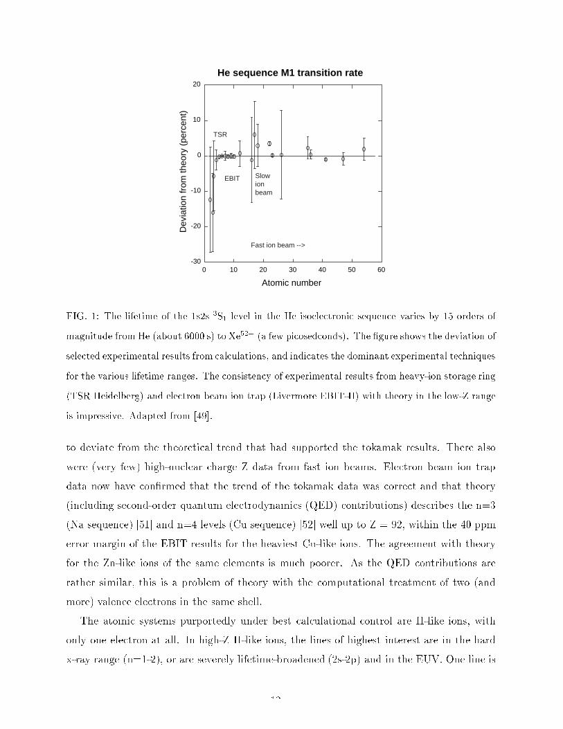
FIG. 1: The lifetime of the 1s2s 3S1 level in the He isoelectronic sequence varies by 15 orders of
magnitude from He (about 6000 s) to Xe52+ (a few picosedconds). The �gure shows the deviation of
selected experimental results from calculations, and indicates the dominant experimental techniques
for the various lifetime ranges. The consistency of experimental results from heavy-ion storage ring
(TSR Heidelberg) and electron beam ion trap (Livermore EBIT-II) with theory in the low-Z range
is impressive. Adapted from [49].
to deviate from the theoretical trend that had supported the tokamak results. There also
were (very few) high-nuclear charge Z data from fast ion beams. Electron beam ion trap
data now have con�rmed that the trend of the tokamak data was correct and that theory
(including second-order quantum electrodynamics (QED) contributions) describes the n=3
(Na sequence) [51] and n=4 levels (Cu sequence) [52] well up to Z = 92, within the 40 ppm
error margin of the EBIT results for the heaviest Cu-like ions. The agreement with theory
for the Zn-like ions of the same elements is much poorer. As the QED contributions are
rather similar, this is a problem of theory with the computational treatment of two (and
more) valence electrons in the same shell.
The atomic systems purportedly under best calculational control are H-like ions, with
only one electron at all. In high-Z H-like ions, the lines of highest interest are in the hard
x-ray range (n=1-2), or are severely lifetime-broadened (2s-2p) and in the EUV. One line is
12

in the visible (for a number of ions), where it is accessible to high-resolution spectroscopy,
and not even notably broadened, because its upper level has a millisecond-range lifetime:
the M1 transition between the hyper�ne levels of the ground state. For two isotopes (of Bi
and Pb), this transition has been induced by laser radiation in a heavy-ion storage ring ([53],
see below), and for 5 isotopes (of Re, Ho, and Tl) emission spectroscopy at the SuperEBIT
electron beam ion trap [55] was successful. Using the ion cloud (with its cross section largely
determined by the electron beam diameter of about 70 �m) as a light source without a further
entrance slit, a high-eÆciency transmission grating spectrometer, and a position-sensitive
detector, lines from two Tl isotopes were recorded simultaneously [54]. The di�erential
e�ects of the two nuclei yielded additional information on the charge distribution in the
nucleus, on top of the magnetic moment distribution that makes up the dominant e�ect.
These results are required for a better interpretation of parity nonconservation (PNC; see
chapter 29) measurements of neutral Tl atoms, in which the nuclear magnetic moments so
far have been treated only as a point dipole. Corresponding measurements are also being
done on Li-like ions, and again the most precise data so far (on Bi) have been obtained at
SuperEBIT.
One of the pertinent problems in astrophysics is the cataloguing of spectral lines in all
spectral ranges, both for identifying spectral features and thus learning about the com-
position of a light source, and for modeling of the light source in order to understand its
\operating conditions". Even data bases that claim \practical completeness", however, are
found to be grossly incomplete in the EUV and soft-x-ray ranges that have been opened to
high-resolution observations by the grating spectrometers on board the Chandra and XMM-
Newton spacecrafts. Here observations at electron beam ion traps �ll in much of the needed
data, at comparable quality. Moreover, EBIT as a kind of analog computer does more than
provide correct line positions: the spectra show line ratios from a light source with known
electron energy (and the option of known temperature by simulating a Maxwellian energy
distribution [55]) and particle density. This serves as, both, a check on collisional-radiative
models and an immediate data resource for astrophysics.
Most x-ray data on EBITs have been collected using solid state detectors (Si(Li), Ge)
that o�er high detection eÆciency (large solid angle) and signal timing on the microsecond
scale, but feature poor spectral resolution. High-resolution instruments like crystal spec-
trometers are necessary to analyze spectra in any detail; equipped with position-sensitive
13
detectors, such instruments do much better than scanning spectrometers in terms of data
collection rate and calibration. However, they su�er from the low di�raction eÆciency of
the crystals. Recently a new device, the microcalorimeter, has started to show its interest-
ing properties. In these devices, small absorbers at mK-temperatures show a measurable
temperature increase when absorbing an x-ray photon, and the signal is proportional to the
deposited photon energy [56]. The line width of the best devices is below 10 eV (not as
good as a crystal spectrometer, but much better than a traditional solid state diode). The
sensor pixels can be grouped in arrays to make for a larger area and for cross references
among pixels (which helps with calibration and with the rejection of cosmic ray events), and
the signal processing is fast enough to permit time resolution on the millisecond range. A
space ight engineering spare has been used at the Livermore EBITs to study, for example,
soft-x-rays of light elements as seen from CX near comets [57], or measure the (10 ms) time
constant of the M3 decay in a Ni-like ion (Xe26+) [58].
Last, but not least, the well de�ned and adjustable electron beam energy permits detail
studies of the interaction of fast electrons with highly charged ions. This includes, for
example, the spectroscopy of dielectronic recombination (DR) resonances, or the exploration
of radiative recombination (RR) (see chapter 53). These processes can be investigated up
to the highest ion charges, where relativistic and QED contributions (like the Generalized
Breit interaction) matter.
B. Heavy-ion storage rings
With foil-excited ion beams and long level lifetimes, decay curves spread out along the
beam, and the signal from a given width of the �eld of view may drop to the detector
background level. The decay lengths of microsecond lifetime levels are on the order of 10 m,
and those of millisecond levels of tens of kilometers. In such cases it is advantageous to curve
the beam line around on itself, forming a storage ring, in which the ions pass in front of
the detector over and over again. Heavy-ion storage rings need excellent vacuum conditions
(10�11 mbar and better) to reach storage times of seconds, minutes, or hours, depending on
the electronic structure of the stored ions and on the ion beam energy. The dominant loss
processes are electron capture and loss, small angle scattering, and large angle (inelastic)
scattering as discussed with any fast ion beams [59], but these contributions are aggravated
14

by the much longer path lengths.
Storage rings (for example, TSR Heidelberg, ASTRID Aarhus, CRYRING Stockholm,
ESR Darmstadt), with magnetic dipoles and quadrupoles for beam transport and focusing,
sort the stored particles by their momentum. The typical ion beam energies range from
a few dozen keV total to hundreds of MeV per nucleon (ESR). Electrostatic storage rings
(ELISA Aarhus and more under construction) have only electrical �elds and select by particle
energy, usually below about 100 keV (for a review, see [60]). They are more suitable for low-
charge heavy ions and ion molecules, including biomolecules, than the magnetic rings that
can handle very fast particles. Magnetic storage rings usually have electron cooler sections
in which a \cool" electron beam (with a low longitudinal velocity spread, from kinematic
compression (see section above) of almost the same velocity as the circulating ion beam is
merged with the latter, for a path of a few meters (and is then de ected out again). By
scattering among electrons and ions, the momentum spread of the electrons (small) and ions
(larger) equilibrates, leaving the ion beam with a narrower momentum distribution and thus
cooled. Cooling typically takes a few seconds, it improves the storage behaviour of the ion
beam and the energy resolution of, for example, dielectronic recombination (DR) studies
(see also chapter 53). For these, the same electron cooler is now tuned to provide electrons
at a well de�ned di�erent velocity. Thus the electron cooler can serve as an electron target,
without the complications of a foil target in beam-foil spectroscopy. The di�erence velocity
can be chosen in a wide range, including zero. Extremely low energy collisions are being
investigated for the study of DR or for the recombination of molecular radicals. When a
beam of molecular ions is injected, storage is long enough to let some of the internal degrees
of freedom relax, and then a beam of molecular ions can be extracted that are closer to their
ground state.
A cooled ion beam with its narrow velocity distribution is also of interest for laser-
ion interaction studies, o�ering higher resolution and better signal. Laser-assisted electron
capture in the electron cooler, as well as laser spectroscopy on high-lying levels populated by
DR, are possible. One of the problems with precision wavelength measurements involving
fast ions is always the accurate determination of the velocity, as a step towards determining
Doppler corrections. At TSR Heidelberg, a beam of Li+ ions was subjected to a laser beam
from ahead, tuned to one of the 2s-2p transitions. A second laser beam from behind probed
the position of the Lamb dip in the velocity distribution and thus assured meeting the
15

same velocity group of the multi-MeV stored ions. Accurate o�-line calibrations of the laser
frequencies then permitted a test of the Doppler formula to a relative precison of 2.2�10�7
[61].
The Doppler shift determination in any observation of fast ions requires accurate angle
measurements. These are nontrivial, because the detection eÆciency of any �nite size spec-
trometer or extended detector may be non-uniform as a function of position or angle. One
technique calls for segmented (\granular") x-ray detectors, the strips of which are calibrated
individually [62]. Relativity changes the emission pattern seen in the laboratory rest frame
to one that favours forward emission. This is bene�cial for zero-degree spectroscopy, that
is an observation along the ion beam path. At ESR Darmstadt, bare ions captured an elec-
tron in the electron cooler section, and resulting x-rays were detected from straight ahead
(behind the next dipole magnet that de ected the ion beam). This geometry maximizes the
Doppler shift, but minimizes the uncertainty as relating to geometry. Also, after electron
capture, the ion in the bending magnet section follows a trajectory that di�ers from that of
the unperturbed ions. The ion can be detected and, in coincidence with the x-ray detector,
make for a very clean and charge-speci�c spectrum. Similar coincidence measurements make
it possible to use a low-pressure gas jet target in a high-energy ion storage ring, evaluating
only coincidences of x-ray photons and charge-changing events [62]. Fast ions (needed to
be so energetic to reach the desired charge state) can also be decelerated in a storage ring,
which helps to do systematic checks of the Doppler e�ect and to work at a lower Doppler
shift [62].
As mentioned in section 18.3.1, laser-resonance techniques have been used to �nd the
ground state hyper�ne transition in two H-like heavy isotopes. In one of them, also the
lifetimewas measured, by recording the uorescence decay from the ion beam after switching
o� the laser [53]. For lower charge states, one can exploit the excitation that ions carry into
the ring from their production in the ion source, or from stripping processes in the injector
accelerator [63]. Lifetimes from half a millisecond to several seconds have been measured that
way by passive observation [49], with an accuracy of better than 0.2% in favourable cases.
Other techniques use excitation by DR in the ring [64], or laser probing of the remaining
metastable level population so that uorescence is emitted near a photomultiplier detector
[65]. With a stored beam of negative ions, even black body radiation may be suÆcient to
photodetach the weakly bound last electron; the ensuing neutral atom is not de ected at the
16
next bending section and leaves the ring to be detected. In summary, lifetimemeasurements
made at heavy-ion storage rings span the enormous range from 10 �s to about 1 minute.
[1] I. Martinson, Rep. Prog. Phys. 52, 157 (1989).
[2] K. Shima, T. Mikumo, and H. Tawara, At. Data Nucl. Data Tables 34, 357 (1986).
[3] T. Andersen and S. Mannervik, Comments At. Mol. Phys. 16, 185 (1985).
[4] F. G. Serpa and A. E. Livingston, Phys. Rev. A 43, 6447 (1991).
[5] C. F. Bunge, Phys. Rev. Lett. 44, 1450, (1980).
[6] E. J. Knystautas, Phys. Rev. Lett. 69, 2635 (1992).
[7] E. Tr�abert, P. H. Heckmann, J. Doerfert, and J. Granzow, J. Phys. B: At. Mol. Opt. Phys.
25, L353, (1992)
[8] S. Mannervik, R. T. Short, D. Sonnek, E. Tr�abert, G. M�oller, V. Lodwig, P. H. Heckmann,
J. H. Blanke, and K. Brand, Phys. Rev. A 39, 3964, (1989)
[9] E. Tr�abert, Physica Scripta 48, 699 (1993).
[10] E. Tr�abert, R. Hutton, I. Martinson Mon. Not. R. Astron. Soc. 227, 27p (1987).
[11] E. Tr�abert Mon. Not. R. Astron. Soc. 297, 399 (1998)
[12] C. Jup�en, P. Bengtsson, L. Engstr�om, and A. E. Livingston, Physica Scripta 64, 329 (2001).
[13] J. O. Stoner and J. A. Leavitt, Opt. Acta 20, 435 (1973).
[14] K.-E. Bergkvist, in Beam Foil Spectroscopy, edited by I. A. Sellin and D. J Pegg (Plenum
Press, New York, 1976), p. 719
[15] G. W. F. Drake, Can. J. Phys. 66, 586 (1988).
[16] A. S. Zacharias, A. E. Livingston. Y. N. Lu, R. F. Ward, H. G. Berry, and R. W. Dunford,
Nucl. Instrum. Meth. Phys. Res. B 31, 41 (1988).
[17] S. W. Provencher, J. Chem. Phys. 64, 2772, (1976).
[18] D. J. G. Irwin and A. E. Livingston, Comput. Phys. Commun. 7, 95 (1974).
[19] P. H. Heckmann, E. Tr�abert, H. Winter, F. Hannebauer, H. H. Bukow, and H. von Buttlar,
Phys. Lett. A 57, 126 (1976).
[20] E. H. Pinnington, W. Ansbacher, J. A. Kernahan, Z.-Q. Ge, and A. S. Inamdar, Nucl. Instrum.
Meth. Phys. Res. B 31, 206 (1988).
[21] R. Geller, App. Phys. Lett. 16, 401 (1970); C. M. Lyneis and T. A. Antaya, Rev. Sci. Instrum.
17

61, 221 (1990).
[22] S. J. Smith, J. A. Lorenzo, S. S. Tayal, and A. Chutjian, Phys. Rev. A 68, 062708 (2003).
[23] J. A. Laming and J. D. Silver, Phys. Lett. A 123, 395 (1987).
[24] G. P. Grandin, D. Hennecart, X. Hussin, D. Lecler, I. Lesteven-Vaisse, and D. Lis�, Europhys.
Lett. 6, 683 (1988).
[25] J. C. Levin, R. T. Short, C.-S. O, H. Cederquist, S. B. Elston, J. P. Gibbons, I. A. Sellin, and
H. Schmidt-B�ocking, Phys. Rev. A 36, 1649 (1987).
[26] developed largely by the groups of H. Schmidt-B�ocking (Frankfurt) and C. L. Cocke (Man-
hattan, Kansas).
[27] M. Barat, Nucl. Instrum. Meth. Phys. Res. B 9, 364 (1985).
[28] M. H. Prior, R. A. Holt, D. Schneider, K. L. Randall, and R. Hutton, Phys. Rev. A 48, 1964
(1993).
[29] D. Schulze-Hagenest, H. Harde, W. Brand and W. Demtr�oder, Z. Phys. A 282, 149 (1977);
H. Schmoranzer and U. Volz, Physica Scripta T47, 42 (1993).
[30] Y. Baudinet-Robinet, P.-D. Dumont, H.-P. Garnir, and A. El. Himdy, Phys. Rev. A 40, 6321
(1989).
[31] T. J. Scholl, R. Cameron, S. D. Rosner, L. Zhang, R. A. Holt, C. J. Sansonetti, and J. D.
Gillaspy, Phys. Rev. Lett. 71, 2188 (1993).
[32] T. P. Dinneen, N. Berrah-Mansour, H. G. Berry, L. Young, and R. C. Pardo, Phys. Rev. Lett.
66, 2859 (1991).
[33] E. J. Myers, J. K. Thompson, E. P. Gavathas, N. R. Clausen, J. D. Silver, and D. J. H. Howie,
Phys. Rev. Lett. 75, 3637 (1995).
[34] T. J. Scholl, S. D. Rosner, and R. A. Holt, Can. J. Phys. 76, 39 (1998).
[35] R. C. Rivest, M. R. Izawa, S. D. Rosner, T. J. Scholl, G. Wu, and R. A. Holt, Can. J. Phys.
80, 557 (2002).
[36] M. L. Gaillard, D. J. Pegg, C. R. Bingham, H. K. Carter, R, L. Mlekodaj, and J. D. Cole,
Phys. Rev. A 26, 1975 (1982).
[37] A. Sen, W. J. Childs, and L. S. Goodman, Nucl. Instrum. Meth. Phys. Res. B 31, 324 (1988).
[38] H. J. Andr�a, R. Fr�ohling, H. J. Pl�ohn, and J. D. Silver, Phys. Rev. Lett. 37, 1212 (1976).
[39] D. Zajfman, O. Heber, L. Vejby-Christensen, I.Ben-Itzhak, M. Rappaport, R. Fishman, and
M. Dahan, Phys. Rev. A 55, 1577 (1997).
18

[40] H. T. Schmidt, H. Cederquist, J. Jensen, and A. Fardi, Nucl. Instrum. Meth. Phys. Res. B
173, 523 (2001).
[41] P. Beiersdorfer, L. Schweikhard, J. Crespo L�opez-Urrutia, and K.Widmann, Rev. Sci. Instrum.
67, 3818 (1996).
[42] L. Schweikhard, P. Beiersdorfer, E. Tr�abert, Non-neutral plasma physics IV: Proc. 2001 Int.
Workshop on Non-neutral Plasmas, San Diego (CA, USA), edited by F. Anderegg, C. F.
Driscoll, and L. Schweikhard, Am. Inst. Phys. Conf. Proc. 606, 174 (2002).
[43] M. A. Levine, R. E. Marrs, J. N. Bardsley, P. Beiersdorfer, C. L. Bennett, M. H. Chen, T.
Cowan, D. Dietrich, J. R. Henderson, D. A. Knapp, A. Osterheld, B. M. Penetrante, M. B.
Schneider, and J. H. Sco�eld, Nucl. Instrum. Meth. B 43, 431 (1989).
[44] M. A. Levine, R. E. Marrs, J. R. Henderson, D. A. Knapp, and M. B. Schneider, Physica
Scripta T 22, 157 (1988).
[45] R. E. Marrs, S. R. Elliott, and D. A. Knapp, Phys. Rev. Lett. 72, 4082 (1994).
[46] F. J. Currell, in Trapping highly charged ions: Fundamentals and applications, edited by J.
Gillaspy, Nova Science Publ., Commack, N.Y., 2001, p. 3
[47] P. Beiersdorfer, A. L. Osterheld, V. Decaux, and K. Widmann, Phys. Rev. Lett. 77, 5353
(1996).
[48] E. Tr�abert, P. Beiersdorfer, G. Gwinner, E. H. Pinnington, and A. Wolf Phys. Rev. A 66,
052507 (2002)
[49] E. Tr�abert, Can. J. Phys. 80, 1481 (2002).
[50] P. Beiersdorfer, E. Tr�abert, and E. H. Pinnington, Astrophys. J. 587, 836 (2003).
[51] P. Beiersdorfer, E. Tr�abert, H. Chen, M.-H. Chen, M. J. May, and A. L. Osterheld, Phys.
Rev. A 67, 052103 (2003).
[52] E. Tr�abert, P. Beiersdorfer, and H. Chen, Phys. Rev. A 70, 032506 (2004).
[53] I. Klaft, S. Borneis, T. Engel, B. Fricke, R. Grieser, G. Huber, T. K�uhl, D. Marx, R. Neumann,
S. Schr�oder, P. Seelig, and L. V�olker, Phys. Rev. Lett. 73, 2425 (1994).
[54] P. Beiersdorfer, S. B. Utter, K. L. Wong, J. R. Crespo L�opez-Urrutia, J. A. Britten, H. Chen,
C. L. Harris, R. S. Thoe, D. B. Thorn, E. Tr�abert, M. G. H. Gustavsson, C. Forss�en, and
A.-M. M�artensson-Pendrill, Phys. Rev. A 64, 032506 (2001).
[55] D. W. Savin, S. M. Kahn, J. Linkemann, A. A. Saghiri, M. Schmitt, M. Grieser, R. Repnow,
D. Schwalm, A. Wolf, T. Bartsch, A. M�uller, S. Schippers, M. H. Chen, N. R. Badnell, T. W.
19

Gorczyca, and O. Zatsarinny, Astrophys. J. 576, 1098 (2002b).
[56] F. S. Porter, M. D. Audley, P. Beiersdorfer, K. R. Boyce, R. P. Brekosky, G. V. Brown, K.
C. Gendreau, J. D. Gygax, S. M. Kahn, R. L. Kelley, C. K. Stahle, A. E. Szymkowiak, Proc.
SPIE 4140, 407 (2000).
[57] P. Beiersdorfer, K. R. Boyce, G. V. Brown, H. Chen, S. M. Kahn, R. L. Kelley, M. May, R.
L. Olson, F. S. Porter, C. K. Stahle, and W. A. Tillotson, Science 300, 1558 (2003).
[58] E. Tr�abert, P. Beiersdorfer, et al., (work in progress)
[59] I. S. Dmitriev, V. S. Nikolaev, and Ya. A. Teplova, Phys. Lett. 26A, 122 (1968).
[60] L. H. Andersen, O. Heber, and D. Zajfman, J. Phys. B 37, R57 (2004).
[61] G. Saatho�, S. Karpuk, U. Eisenbarth, G. Huber, S. Krohn, R. Mu~noz Horta, S. Reinhardt,
D. Schwalm, A. Wolf, and G. Gwinner, Phys. Rev. Lett. 91, 190403 (2003).
[62] Th. St�ohlker, P. H. Mokler, F. Bosch, R. W. Dunford, F. Franzke, O. Klepper, C. Kozhuharov,
T. Ludziejewski, F. Nolden, H. Reich, P. Rymuza, Z. Stachura, M. Steck, P. Swiat, and A.
Warczak, Phys. Rev. Lett. 85, 3109 (2000).
[63] J. Doerfert, E. Tr�abert, A. Wolf, D. Schwalm, and O. Uwira Phys. Rev. Lett. 78, 4355 (1997)
[64] Schmidt, H.T., Forck, P., Grieser, M., Habs, D., Kenntner, J., Miersch, G., Repnow, R.,
Schramm, U., Sch�ussler, T., Schwalm, D., and Wolf, A., Phys. Rev. Lett. 72, 1616 (1994).
[65] S. Mannervik, Physica Scripta T 105, 67 (2003).
20
Top Related