


Languages
Pages
Legal

Slicing Packet Network (SPN) Enabling 5G Transport Network
Weiqiang Cheng China Mobile

2
New challenges to 5G transport network
eMBB
uRLLC
mMTC
5G new scenarios
New challenges to transport network
Service Requirement
Changes
Delay
10ms->1ms
One-way Delay
Sync
1.5us->400ns
Time Sync.
Slicing
For different service types
and attributes
Networking architecture
Changes
5G RAN:
CU/DU separation
5G Core:
Cloud core network, UPF closed to
user,MEC
Connections between network element devices
change into
The interconnection between clouds,which needs to be unified and
flexible.
5G_CP
mMTC CP/UP
5G_CP
5G_UP 5G_UP
5G_CP
5G_UP 5G_UP
infrastructure Requirement
Changes
Fiber: The density of the site is higher, which promotes the
pressure of the terminal fiber.
Machine Room: More new equipments, higher requirements for room, power
supply and heat dissipation.
320M->10G
bps/Single Station
Bandwidth
The Requirements of 5G transmission network have changed greatly and need to be re-architected.
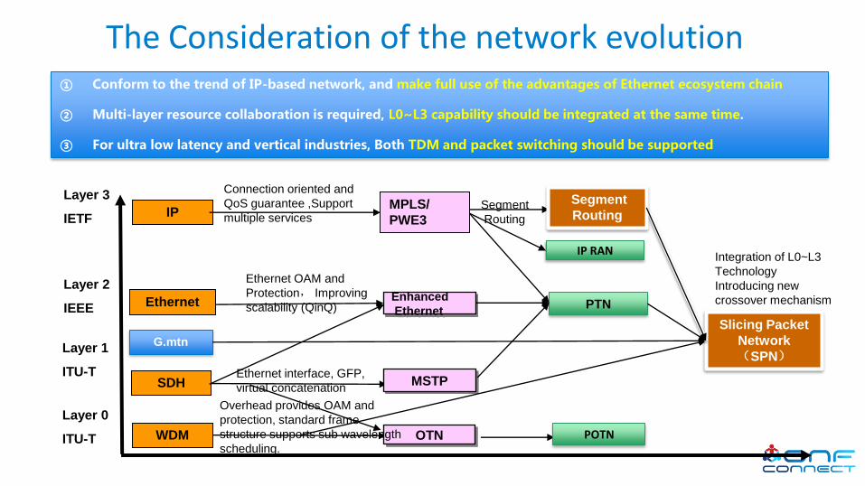
The Consideration of the network evolution ① Conform to the trend of IP-based network, and make full use of the advantages of Ethernet ecosystem chain
② Multi-layer resource collaboration is required, L0~L3 capability should be integrated at the same time.
③ For ultra low latency and vertical industries, Both TDM and packet switching should be supported
MSTP
Enhanced
Ethernet
MPLS/
PWE3
Ethernet
IP
SDH
Ethernet OAM and
Protection, Improving
scalability (QinQ)
Ethernet interface, GFP,
virtual concatenation
Connection oriented and
QoS guarantee ,Support
multiple services
Layer 1
ITU-T
Layer 2
IEEE
Layer 3
IETF
OTN
PTN
POTN
IP RAN
Layer 0
ITU-T WDM
Overhead provides OAM and
protection, standard frame
structure supports sub wavelength
scheduling.
G.mtn
Slicing Packet
Network (SPN)
Segment
Routing Segment
Routing
Integration of L0~L3
Technology
Introducing new
crossover mechanism

SPN Arch: Integrates L0~L3 multilayer functions
① L2&L3: MPLS-TP and SR-TP
SPL (Slicing Packet Layer)
SCL (Slicing Channel Layer)
STL (Slicing Transport Layer)
Segment Routing
L2/L3 VPN
G.mtn Path layer
MAC
CBR service
CBR adaptation
Time / Clock
SDN Controll
er
1
2
3
Flexible bearer and network programming for multiple services
Slicing Ethernet implements low latency and hard isolation
Efficient and high-bandwidth transmission
G.mtn Section layer
DWDM+Siplified OADM
② L1: 66B block based TDM switching
④ SDN centralized control
ITU-T SPN project has been approved as the G.mtn project, which marks a new generation of transport network
research in ITU-T.
③ L0: WDM and simplified OADM
4
Eth Phy

Ethernet Mac
MPLS-TP
DWDM/ROADM
SR-TP/SR-BE
L0:Optical
L1:Physical
PMD
PMA
FEC
MTN Section
MTN Path
PCS upper part
L2:Data Link
L3:IP layer
Ethernet Mac
MPLS-TP Tunnel
SR Tunnel
MDI
PCS lower part(transcoder)
SPN layer structure evolution SPN protocol stack architecture
SPN innovatively introduces SPN channel layer, integrates TDM and packet switching, and integrates L0 layer to L3 layer into an organic whole.
MAC and upper Layers
RS/PCS_upper
Paht: 66B Swithing
Section: Reuse FlexE
PCS_lower/PMA/PMD
MAC and upper Layers
RS/PCS_upper
OIF FlexE SHIM
PCS_lower/PMA/PMD
MAC and upper Layers
RS/PCS
PMA/PMD
G.mtnFlexEStandard Ethernet
SPN protocol stack

Ethernet Optical Layer Interface Requirements
50GE (25G
PAM4)
50GE
200GE
400GE
1*ƛ
4*ƛ
8*ƛ
Fronthaul Requirements: fiber direct drive, large core fiber,25GE BIDI module
Middlehaul/Backhaul(small city):E2E gray Ethernet networking ,50GE PAM4*N
Middlehaul/Backhaul(large city):access with gray Ethernet, aggregation / core with DWDM
• Coherent Ethernet Color Light Module
• 400G ZR
• 200G ZR
• 100G ZR
Netw
orkin
g Sche
me
In
terface
Techn
olo
gy
Gray Ethernet module requirements Color Ethernet module requirements
Core Layer Aggregation Layer Access Layer
DU+MEC
DU
DU
DU
SPN
10G/25G CPRI/eCPRI
3G/4G/5G
RRU/AAU 10G/25G
CPRI/eCPRI
前传 3G/4G/5G
RRU/AAU
Single fiber bidirectional connection to reduce fiber consumption, maintain time synchronization and high performance delivery ( to avoid errors introduced by asymmetric fiber length )
support 5G transmission, OLT uplink and other integrated services
Distance : •2km •10km •40km • Distance : •80km •120km
G.mtn
64/66b 64/66b
Client Client
Interface
Interface
Feature 1 :Sub-interface Feature 2: Channelized isolation
G.mtn
64/66b 64/66b
Client Client
Interface
Interface
Feature 2 :Interface Bonding
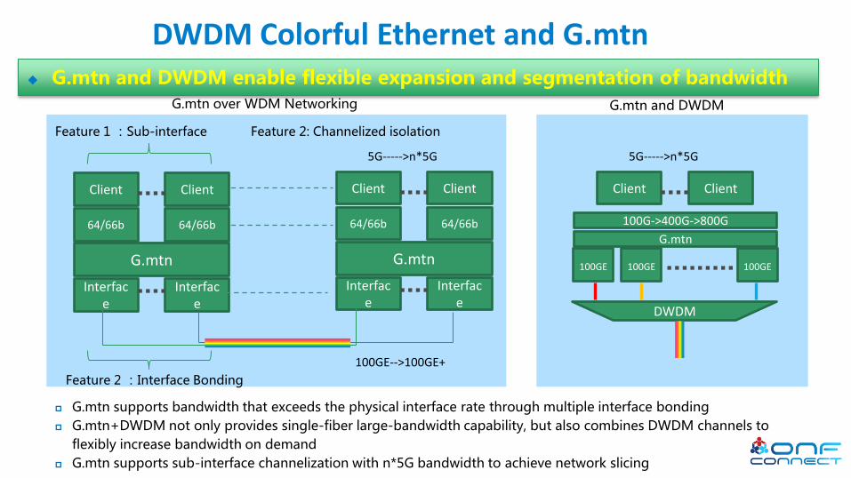
G.mtn over WDM Networking
G.mtn supports bandwidth that exceeds the physical interface rate through multiple interface bonding
G.mtn+DWDM not only provides single-fiber large-bandwidth capability, but also combines DWDM channels to
flexibly increase bandwidth on demand
G.mtn supports sub-interface channelization with n*5G bandwidth to achieve network slicing
100GE-->100GE+
5G----->n*5G
G.mtn
Client Client
5G----->n*5G
DWDM
100GE 100GE 100GE
100G->400G->800G
G.mtn and DWDM
G.mtn and DWDM enable flexible expansion and segmentation of bandwidth
DWDM Colorful Ethernet and G.mtn

The Path Layer cross connection and OAM
New Switch: based on 66bit Slot which is the basic block of original Ethernet
New OAM:Using the IDEL block slot as the OAM message block slot and provide OTN like OAM
Client 1
64b/66b 64/66B
OAM 66b Switch
ETH Group A
20 slots mx20
OH
PHY1
OH
PHY2
OH
PHYm
IDL A/D
ETH Group B
20 slots mx20
1 2 3 4 5 6 7 8 9 10 11
12
14
15
16
18
20
13
17
19 1 2 3 4 5 6 7 8 9
10 11
12
14
15
16
18
20
13
17
19
OH
PHY1
OH
PHY2
OH
PHYm
IDL A/D
Client 2
64b/66b 64/66B
OAM
IDL A/D
Path layer Client3
IDL A/D
Path layer Client3
L2/L3 Switch
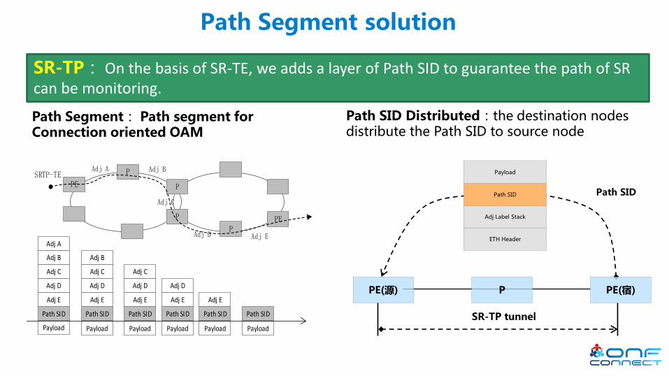
Path Segment solution
SR-TP: On the basis of SR-TE, we adds a layer of Path SID to guarantee the path of SR can be monitoring.
Path Segment: Path segment for Connection oriented OAM
P PE(源) PE(宿)
SR-TP tunnel
ETH Header
Adj Label Stack
Path SID
Payload
Path SID
Path SID Distributed:the destination nodes distribute the Path SID to source node
Payload Payload Payload Payload Payload Payload
PE
P
P
P
PPE
Adj A Adj B
Adj C
Adj D Adj E
SRTP-TE
Adj E
Adj D
Adj C
Adj B
Adj A
Path SID
Adj E
Adj D
Adj C
Adj B
Path SID
Adj E
Adj D
Adj C
Path SID
Adj E
Adj D
Path SID
Adj E
Path SID Path SID
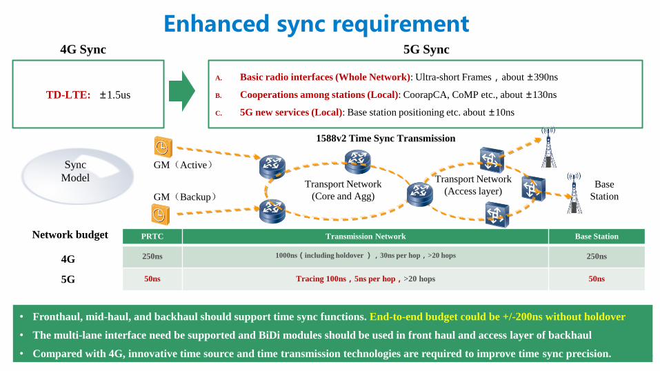
Enhanced sync requirement 5G Sync
A. Basic radio interfaces (Whole Network): Ultra-short Frames,about ±390ns
B. Cooperations among stations (Local): CoorapCA, CoMP etc., about ±130ns
C. 5G new services (Local): Base station positioning etc. about ±10ns
4G Sync
TD-LTE: ±1.5us
Sync
Model Transport Network
(Core and Agg)
Transport Network
(Access layer) GM(Backup)
GM(Active)
1588v2 Time Sync Transmission
Base
Station
Network budget
4G
5G
PRTC Transmission Network Base Station
250ns 1000ns(including holdover ),30ns per hop,>20 hops 250ns
50ns Tracing 100ns,5ns per hop,>20 hops 50ns
• Fronthaul, mid-haul, and backhaul should support time sync functions. End-to-end budget could be +/-200ns without holdover
• The multi-lane interface need be supported and BiDi modules should be used in front haul and access layer of backhaul
• Compared with 4G, innovative time source and time transmission technologies are required to improve time sync precision.
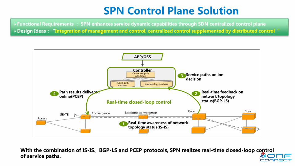
Convergence Core
Access
Backbone convergence Core
Real-time awareness of network topology status(IS-IS)
Service paths online decision
Path results delivered online(PCEP)
Real-time closed-loop control
SR-TE
Link topology database
Centralized path calculation
Tunnel path database
Controller
1
2 Real-time feedback on network topology status(BGP-LS)
3
4
APP/OSS
SPN Control Plane Solution
With the combination of IS-IS、BGP-LS and PCEP protocols, SPN realizes real-time closed-loop control of service paths.
Functional Requirements : SPN enhances service dynamic capabilities through SDN centralized control plane
Design Ideas:“Integration of management and control, centralized control supplemented by distributed control“

L1:TDM
L2 VPN
L3 VPN
uRLLC
mMTC
Enterprise private line
eMBB
Internet
High reliability
Sensitive to delay
Large bandwidth
General reliability
Non-sensitive to
delay Software
isolation
Hardware isolation
SPN Network Slice Presenting
SPN Controller
ONAP
wireless VNFC
Core Network
VNFC SDN-O
NE1 NE2 NE3 NE4 NE5
NE6 NE7 NE8
SPN Physical Network View
mMTC uRLLC
Slice subnet control
SPN Network Slicing:With the management and control plane integration, SPN
implements logical abstraction of physical resources , achieving "one physical network and
multiple networking architectures”.
Centralized Controller Achieving Network Slicing
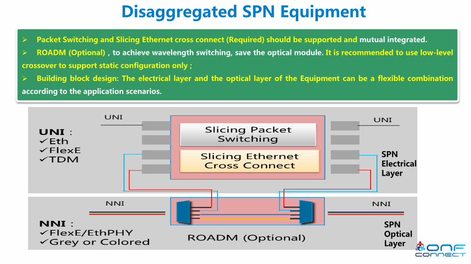
Disaggregated SPN Equipment
Packet Switching and Slicing Ethernet cross connect (Required) should be supported and mutual integrated.
ROADM (Optional),to achieve wavelength switching, save the optical module. It is recommended to use low-level
crossover to support static configuration only ;
Building block design: The electrical layer and the optical layer of the Equipment can be a flexible combination
according to the application scenarios.
SPN Electrical Layer
SPN Optical Layer

Thank You
Follow Up Links: XXXX
Top Related