


Languages
Pages
Legal

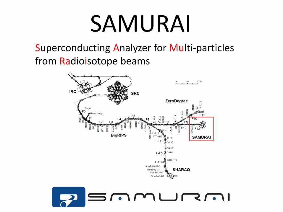
SAMURAI Superconducting Analyzer for Multi-particles from Radioisotope beams

Overview The SAMURAI spectrometer is designed for kinematically complete reaction measurements by detecting multiple particles in coincidence.
Superconducting dipole magnet Heavy Ion detectors Proton detectors Neutron detectors Large vacuum chamber Rotatable base
SAMURAI consists of …
Large angular- and momentum-acceptance
Large pole gap
Wide horizontal opening of a yoke
The construction of the SAMURAI was completed in Feb. 2012.

Requirements for Magnet • Requirements
– Large field integral --> for high precision momentum analysis – Large pole gap --> for large vertical acceptance for neutrons – No coil link --> for large acceptance in the horizontal direction – Small fringing field --> for detectors around the target region and tracking detectors – Flexibility --> for various experimental conditions – Large momentum acceptance --> for heavy fragments and protons in coincidence – High momentum resolution --> for deuteron-induced reactions
Field Integral 7 Tm (dR/R ~ 1/700 @ 2.3 GeV/c for A/Z=3) --> mass separation σA=0.2 for A=100 Large Gap (0.8 m --> vertical ±5 degrees) Large opening (3.4 m --> holizontal ±10 degrees) Small Fringing Field (< 50 gauss @ 50cm from magnet) H-type magnet with cylinder poles (2m in diameter) Magnetic field … about 3T at center by ~1.9MAT Field clamp Build-in vacuum chamber Rotatable base (from -5 to 95 deg, 0.1deg/sec)

Versatile usage Magnet can rotate around it’s center.
Flexibility of settings is one of the good properties of SAMURAI.
(γ, n) reaction: neutron-rich side (γ, p) reaction: proton-rich side (p,p’), (p,2p), (p,pn), …
pol. d-induced reaction EOS measurement
0
90 30deg 90deg 45deg
30deg 0deg

Photo
LHe reservoir vessels target
upstream side view
Vacuum chamber
* The magnet was rotated at an angle of 30o.
Field cramp

Yoke
field clamp hole
hole
880

Yoke cutaway view at median plane pole (2m dia.)
side yoke
top view
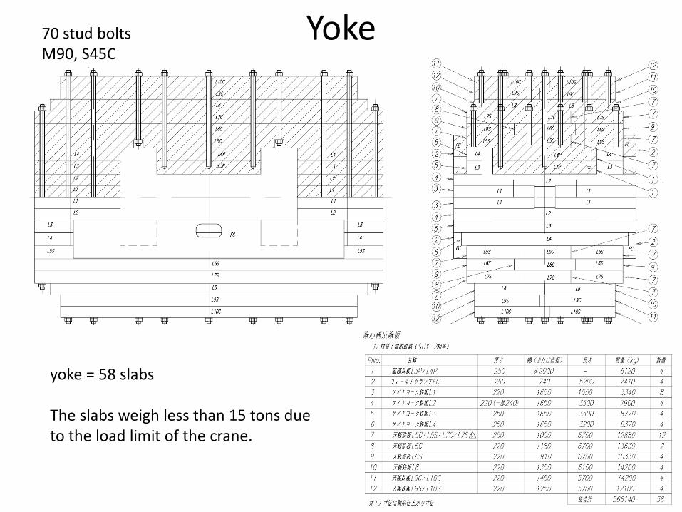
Yoke 70 stud bolts M90, S45C
yoke = 58 slabs The slabs weigh less than 15 tons due to the load limit of the crane.

Specifications of the soft steel
Company: JFE Steel Corporation Product name: Hot Rolled Steel Plate Model: JFE-EFE 2003 SPEC: SUY-2 (defined in JISC2504)
Chemical components
C Si Mn P S Cu Cr Mo Al N
[%](mass) < 0.03 < 0.20 < 0.50 < 0.03 < 0.03 (0.15) (0.05) (0.02) (0.06) (0.01)
Mechanical properties
0.2% proof stress > 120 MPa
tensile strength > 220 MPa
Elongation > 20%
DC magnetic properties
H [A/m] 300 500 1000 4000
B [T] > 1.15 > 1.30 > 1.45 > 1.60
coercive field strength < 100 A/m @1.5 T
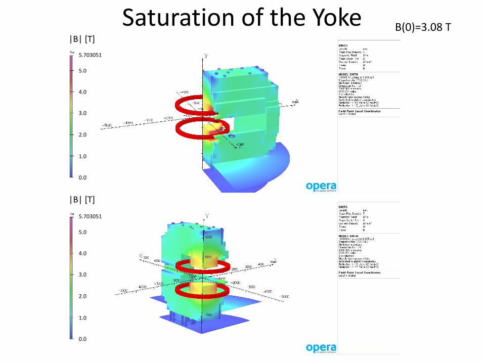
Saturation of the Yoke |B| [T]
|B| [T]
5.703051
5.0
4.0
3.0
2.0
1.0
0.0
5.703051
5.0
4.0
3.0
2.0
1.0
0.0
B(0)=3.08 T

field integral
B=3.08T
Field clamp Field clamp (W5400 x H740 x D250) was designed so as to obtain smaller fringe field.
2.2 < Z < 5.0
Thickness dependence
W5400 x H740 x D***
Width dependence
W**** x H740 x D250
field integral 2.2 < Z < 5.0 2.2 < Z < 5.0
field integral
Height dependence
W5200 x H*** x D250
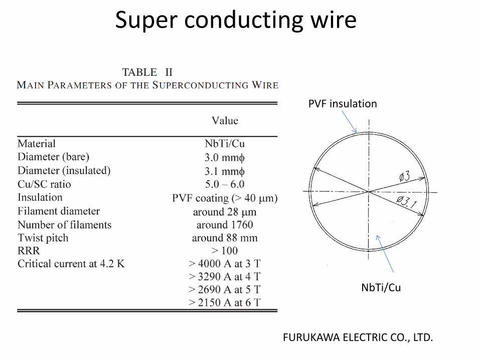
Super conducting wire
FURUKAWA ELECTRIC CO., LTD.
PVF insulation
NbTi/Cu
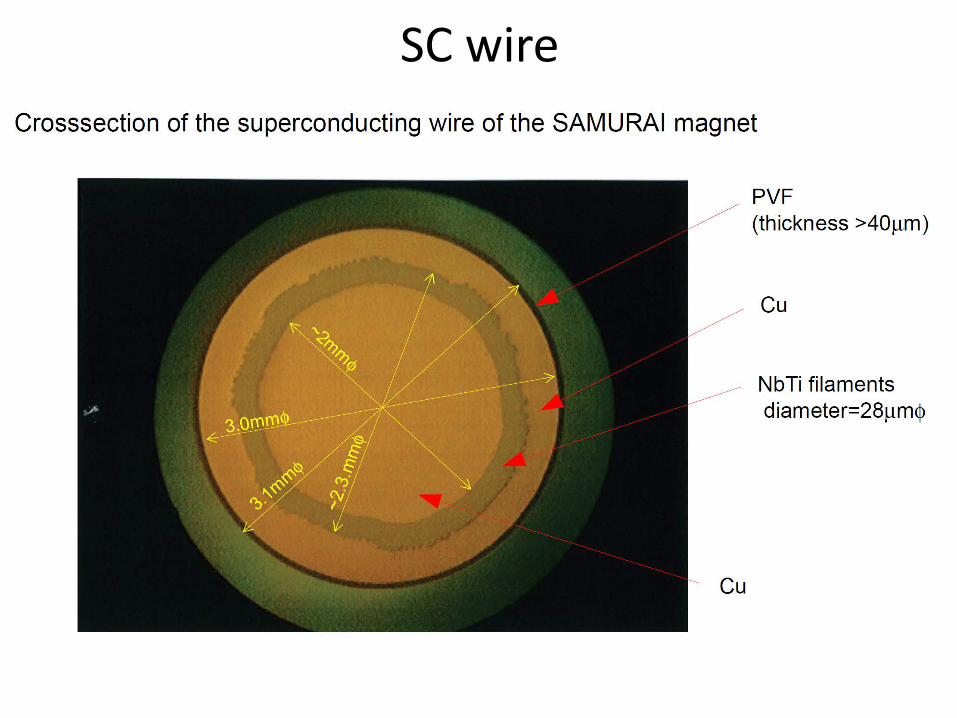
SC wire

SC wire

SC wire
Ic @4.2K
Ic @5K
Ic @6K
Ic @7K
Load Line
563 A 5.4 T
Load factor : 60% @4.2K

Specifications of the coil
NOT stabilized Wet winding using the special
epoxy resin

Coil vessel
pre-stress radially by welding
SUS316L
LHe
tube (φ10x1t)
LHe: 57.4 L
total weight: 3 ton coil: 1.8 ton vessel: 1.2 ton
welding
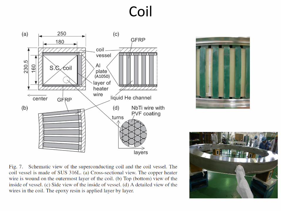
Coil
(A1050)
Coil
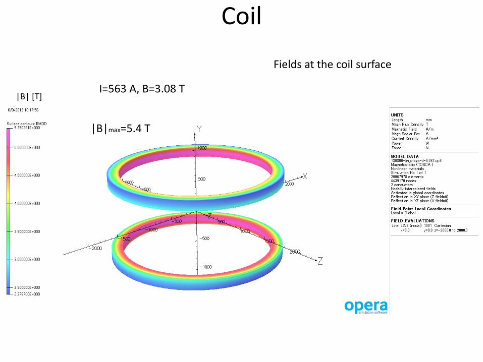
I=563 A, B=3.08 T |B| [T]
Fields at the coil surface
|B|max=5.4 T
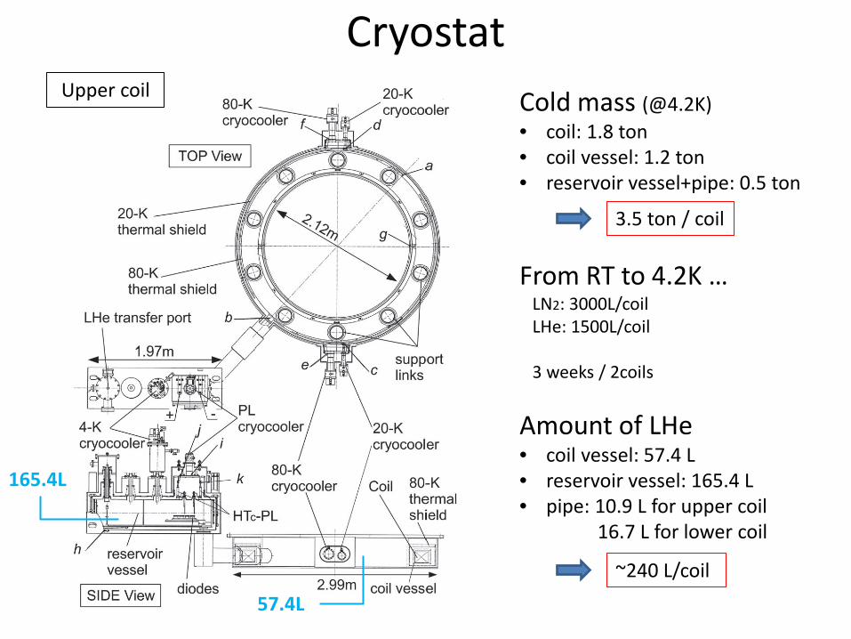
Cryostat Cold mass (@4.2K) • coil: 1.8 ton • coil vessel: 1.2 ton • reservoir vessel+pipe: 0.5 ton
3.5 ton / coil
From RT to 4.2K … LN2: 3000L/coil LHe: 1500L/coil 3 weeks / 2coils
Amount of LHe • coil vessel: 57.4 L • reservoir vessel: 165.4 L • pipe: 10.9 L for upper coil 16.7 L for lower coil
~240 L/coil
Upper coil
57.4L
165.4L

Cryostat
suspension rod (GFRP)
support link (GFRP) (SUS304N2)
coil
cryostat (SUS304)
80K shield (A1050) (A5083)
20K (pure AL)
4.2K coil vessel (SUS316L)
GFRP SUS304N2

Estimated Heat load/coil
Place Parts Heat load @ramping @I=560 A @I=0 A
In the cryostat + Chimney pipe
Thermal shield Radiation 0.40 0.40 0.40
Support Conduction 1.35 1.35 1.35
Coil AC loss 0.50 0.00 0.00
In the reservoir vessel (port)
Thermal shield Radiation 0.52 0.52 0.52
Support Conduction 0.04 0.04 0.04
Power leads Conduction + Joule loss
0.54 0.54 0.30
He gas Conduction 0.57 0.57 0.57
Bellows 0.07 0.07 0.07
Signal leads 0.12 0.12 0.12
Sum 4.11 3.61 3.37
Place Parts Heat load @ramping @I=560 A @I=0 A
In the cryostat Thermal Shield Radiation 0.08 0.08 0.08
Support Conduction 4.88 4.88 4.88
Sum 4.96 4.96 4.96
4K part
20K part
GM/JT [email protected] x2
GM 4.2W@12K x2
( calculated for the lower coil )

Estimated Heat load/coil
Place Parts Heat load @ramping @I=560 A @I=0 A
In the cryostat + Chimney pipe
Thermal shield Radiation 23.79 23.79 23.79
Residual gas 0.60 0.60 0.60
Support Conduction 53.83 53.83 53.83
Sum 78.22 78.22 78.22
Place Parts Heat load @ramping @I=560 A @I=0 A
In the reservoir vessel (port)
Vacuum chamber Radiation 10.99 10.99 10.99
Residual gas 0.28 0.28 0.28
Support Conduction 0.47 0.47 0.47
Power lead Conduction + Joule loss
40.496 40.496 22.344
Bellows Conduction 1.708 1.708 1.708
Sum 53.94 53.94 35.78
80K thermal shield
Power lead
GM 54W@40K x1
GM 100W@80K x2

Heat load @4K Heat load @4K /coil (estimation)
@Ramping [W] @I=560 A [W] @I=0 A [W]
4 K part 4.11 3.61 3.37
LHe
pressure
1.25 L/h
Time [hour]
LHe
[L]
Pres
sure
in v
esse
l [kP
aG]
Upper cryostat
Time [hour]
LHe
pressure
2.05 L/h LHe
[L]
Pres
sure
in v
esse
l [kP
aG]
Lower cryostat
Evaporation rate of LHe (measurement @I=0 A)
0.9 W 1.5 W
Two GM/JTs were prepared, but the measured heat load is smaller than the estimated value. Thus, just one GM/JT is used now.
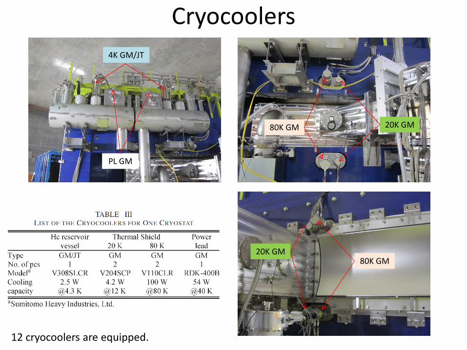
Cryocoolers
12 cryocoolers are equipped.
4K GM/JT
80K GM 20K GM
20K GM 80K GM
PL GM

Temperature monitor screen of the controller (6 Sept. 2013)
Place Upper coil
[K]
Lower coil
[K]
a He vessel (outside of the wall) 4.2 4.3
b He vessel (port) 7.1 7.1
c 20K GM A 11.8 11.9
d 20K GM B 11.6 11.2
e 80K GM A 40.9 43.3
f 80K GM B 41.6 40.6
g 80K thermal shield 45.1 47.5
h 80K thermal shield (reservoir vessel)
45.3 43.8
i PL GM 42.6 41.5
j PL (+) 42.9 41.6
k PL (−) 42.8 41.6

Structural Analysis FEM analysis: coil + coil vessel + support link
coil
Support link
Coil vessel (SUS316L)
Fr=5x10³ kN (2000ton/coil) Fy=1.5x10³ kN (600ton/coil)
coil
Fr coil
Fy
Magnetic forces as a function of the azimuthal angle
GFRP(25mm)
20mm
Al(3mm)
25mm GFRP(12mm)
GFRP(7mm)
Al(3mm) 20mm
20mm
GFRP(5mm)
integrate
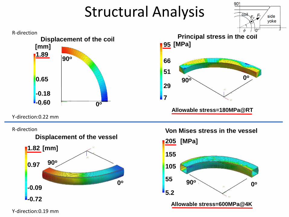
Structural Analysis
1.89
0.65
-0.18 -0.60
[mm] Displacement of the coil
0o
90o
Displacement of the vessel 1.82 [mm]
0.97
-0.09
-0.72
0o
90o
90o 0o
Principal stress in the coil 95 [MPa]
7
51 66
29
Allowable stress=180MPa@RT
Von Mises stress in the vessel
0o 90o
[MPa] 205
105
5.2
55
155
Allowable stress=600MPa@4K
R-direction
Y-direction:0.22 mm
R-direction
Y-direction:0.19 mm
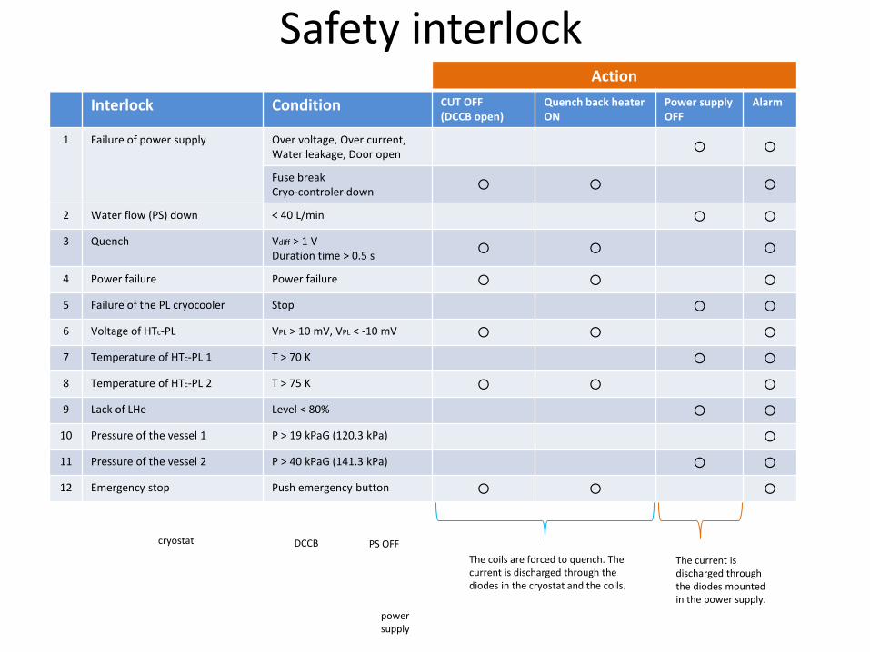
Safety interlock Action
Interlock Condition CUT OFF (DCCB open)
Quench back heater ON
Power supply OFF
Alarm
1 Failure of power supply Over voltage, Over current, Water leakage, Door open
Fuse break Cryo-controler down
2 Water flow (PS) down < 40 L/min
3 Quench Vdiff > 1 V Duration time > 0.5 s
4 Power failure Power failure
5 Failure of the PL cryocooler Stop
6 Voltage of HTc-PL VPL > 10 mV, VPL < -10 mV
7 Temperature of HTc-PL 1 T > 70 K
8 Temperature of HTc-PL 2 T > 75 K
9 Lack of LHe Level < 80%
10 Pressure of the vessel 1 P > 19 kPaG (120.3 kPa)
11 Pressure of the vessel 2 P > 40 kPaG (141.3 kPa)
12 Emergency stop Push emergency button
DCCB PS OFF cryostat
power supply
The coils are forced to quench. The current is discharged through the diodes in the cryostat and the coils.
The current is discharged through the diodes mounted in the power supply.

Quench protection
1. The detector recognizes the quench. (1V, 0.5s) 2. DCCB open (Coils are cut off.) 3. Current flows to the heater layer on the outermost of the coil. 4. Backup heaters switch on within 50 ms. 5. Coils are forced to quench from the outer to inner layer. 6. Stored energy is dumped by the superconducting coils.
In the case …
• cryo-conroler down • power failure • |VPL| > 10 mV • TPL > 75 K • emergency stop
Quench
Same procedure as the quench case will be done.
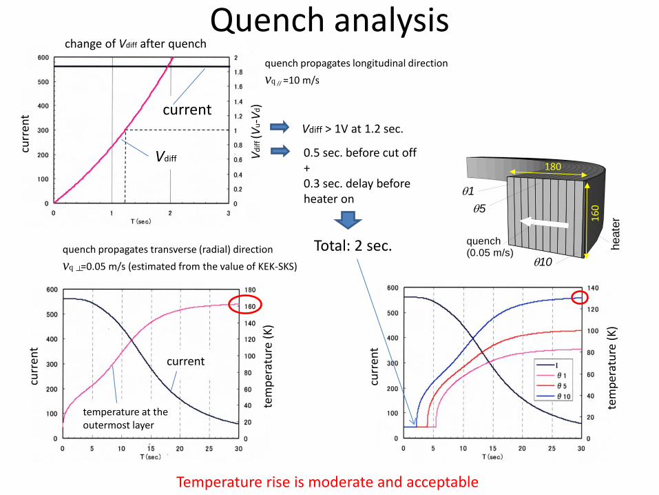
Quench analysis
θ10
θ5θ1
quench (0.05 m/s) he
ater
180
160
current
Vdiff
curr
ent
Vdiff
(Vu-
Vd)
change of Vdiff after quench quench propagates longitudinal direction vq =10 m/s
quench propagates transverse (radial) direction vq =0.05 m/s (estimated from the value of KEK-SKS)
curr
ent
tem
pera
ture
(K)
curr
ent
tem
pera
ture
(K)
current
temperature at the outermost layer
Vdiff > 1V at 1.2 sec.
0.5 sec. before cut off + 0.3 sec. delay before heater on
Total: 2 sec.
Temperature rise is moderate and acceptable

Quench analysis
Induced voltage is moderate and acceptable
θ10
θ5θ1
quench (0.05 m/s) he
ater
180
160
(a) (b)
(c) ~700 V

Coil protection In the case …
1. Power supply is cut off
2. Stored energy is dumped by diodes in the power supply
3. Diodes are cooled by heat-sink and fan
from 560A to 0A : ~1 hour
decay const. : 0.25A/sec
• over voltage • over current • door open • water leakage • water flow down • PL cryocooler failure • TPL > 70 K • LHe level < 80% • pHe > 40 kPaG

Cryostat assembling
coil winding

Cryostat assembling reservoir vessel cryostat chamber

Cryostat assembling Lower cryostat assembling
support link
coil vessel part of 80K shield
part of cryostat chamber
support link

Cryostat assembling
coil vessel
pipe for liq. He transfer
80K shield
80K shield
80K shield
20K GM head is attached here
support links

Cryostat assembling
coil vessel
80K shield
suspension rod (GFRP)
Upper cryostat Upper cryostat
Lower coil

Cryostat assembling Upper cryostat
cryostat chamber
20K GM 80K GM

Cryostat assembling Upper cryostat LHe
transfer port current port
Lower cryostat
reservoir vessel
PL GM
4K GM/JT port
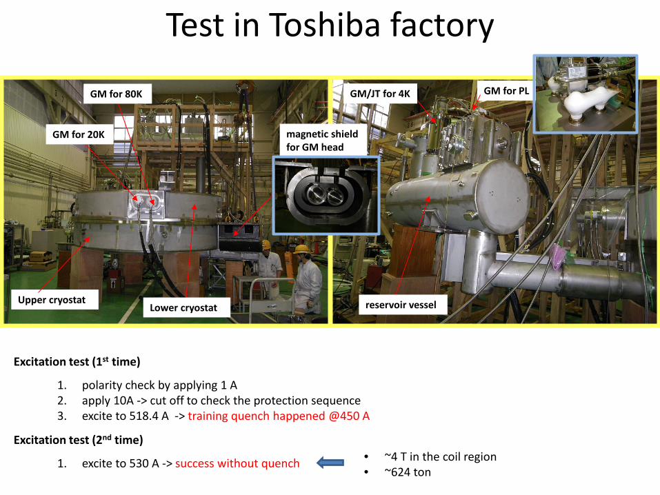
Test in Toshiba factory
Excitation test (1st time)
GM for 80K
GM for 20K
GM/JT for 4K
reservoir vessel
GM for PL
magnetic shield for GM head
Upper cryostat Lower cryostat
1. polarity check by applying 1 A 2. apply 10A -> cut off to check the protection sequence 3. excite to 518.4 A -> training quench happened @450 A
Excitation test (2nd time)
1. excite to 530 A -> success without quench • ~4 T in the coil region • ~624 ton

On site assembling
Rails for rotatable base (11/13/2010)
Rotatable base with the first layer of the yoke
Magnet yoke with poles
Coils with cryostats, LHe reservoir vessels
Vacuum chamber After day-one experiments (9/19/2012)

Excitation test May 2011, excitation test was performed.
A training quench happened in the lower coil at 561 A (3.07 T), which corresponds to 99.6% of the maximum operation current, 563 A (3.08 T). During subsequent excitation testing after refilling of LHe, the current reached 563 A without quenching and the test was continued up to 573 A (3.10 T) successfully.

Magnetic Field
They are determined in response to changes is the inductance of the coil so as to keep the induced voltage below 20 V, which is the maximum voltage of the power supply.
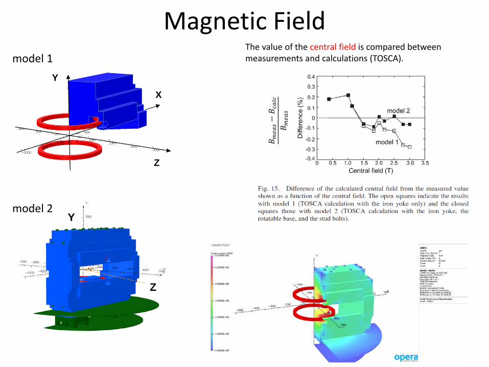
Magnetic Field
Y
Z
Y
Z
X
model 1
model 2
The value of the central field is compared between measurements and calculations (TOSCA).
𝐵𝐵 𝑚𝑚𝑚𝑚𝑚𝑚𝑚𝑚−𝐵𝐵 𝑐𝑐
𝑚𝑚𝑐𝑐𝑐𝑐
𝐵𝐵 𝑚𝑚𝑚𝑚𝑚𝑚𝑚𝑚

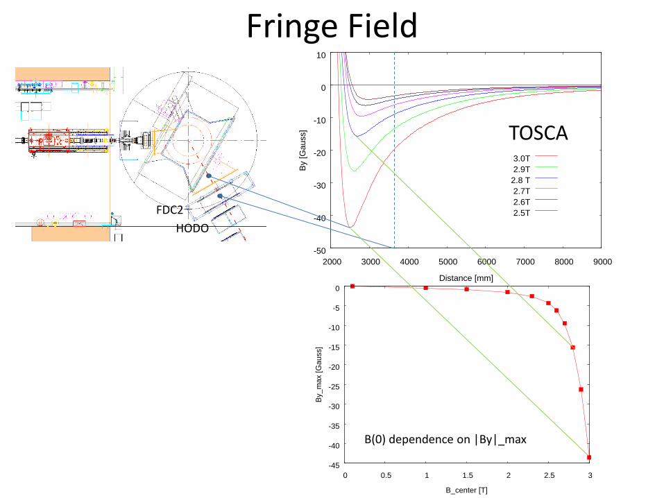
Fringe Field
FDC2
B(0) dependence on |By|_max
By [G
auss
] distance [mm]
B(0) [T]
HODO
TOSCA
|By|
_max
[Gau
ss]
-45
-40
-35
-30
-25
-20
-15
-10
-5
0
0 0.5 1 1.5 2 2.5 3
By_m
ax [G
auss
]
B_center [T]
-50
-40
-30
-20
-10
0
10
2000 3000 4000 5000 6000 7000 8000 9000
By [G
auss
]
Distance [mm]
3.0T2.9T2.8 T2.7T2.6T2.5T
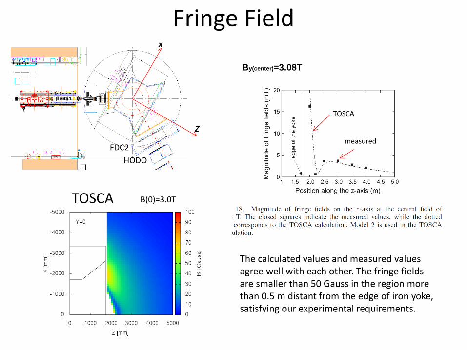
Fringe Field
FDC2
B(0) dependence on |By|_max
HODO
TOSCA
Fringe Field
By(center)=3.08T
TOSCA
measured
TOSCA B(0)=3.0T
FDC2 HODO
Z
x
The calculated values and measured values agree well with each other. The fringe fields are smaller than 50 Gauss in the region more than 0.5 m distant from the edge of iron yoke, satisfying our experimental requirements.

Summary
Large-acceptance spectrometer “SAMURAI” has been constructed at RIKEN RIBF.
The construction of the H-type superconducting dipole magnet was finished in June 2011.
Large pole gap (800mm effectively)
Wide horizontal opening (3400mm)
Central field =3.08T, BL=7.05Tm, I=563A, E=27.4MJ
The coils are cooled by liquid He.
Twelve cryocoolers are used to keep the temperature.
The first reaction experiments using SAMURAI were carried out in May 2012, and the second experiments were carried out in April 2013.
Top Related