
Persona® Kinematically Aligned Total Knee …...5 | Persona Kinematically Aligned Total Knee...
64
Persona ® Kinematically Aligned Total Knee Arthroplasty Surgical Technique
Transcript of Persona® Kinematically Aligned Total Knee …...5 | Persona Kinematically Aligned Total Knee...

Persona® Kinematically Aligned Total Knee Arthroplasty
Surgical Technique


Table of Contents
Introduction .............................................................................................................. 2
Preoperative Planning .............................................................................................. 6
Expose and Assess the Knee .................................................................................... 6
Resect Distal Femur .................................................................................................. 7
Size Femur and Establish External Rotation .......................................................... 14
Complete Femoral Resections and Measure Thicknesses ..................................... 17
Locate the A/P Axis of the Tibia .............................................................................. 23
Resect Proximal Tibia ............................................................................................. 24
Check Extension Gap .............................................................................................. 32
Check Flexion Gap .................................................................................................. 33
Establish Size of the Tibia ....................................................................................... 33
Initial Trial Reduction .............................................................................................. 35
Restore V/V and I/E Laxity ..................................................................................... 42
Drill and Broach Tibia.............................................................................................. 45
Prepare the Patella ................................................................................................. 50
CR Femoral Finishing and Final Trial Reduction ..................................................... 54
Implant Components .............................................................................................. 55
Optional Techniques ............................................................................................... 60 2 Degrees Valgus Recut Guide ........................................................................... 60 2 Degrees Varus Recut Guide ............................................................................ 60
Compatibility Charts .............................................................................................. 61

2 | Persona Kinematically Aligned Total Knee Arthroplasty Surgical Technique
Figure 1
IntroductionA Kinematic Alignment (KA) Total Knee Arthroplasty (TKA) strives to restore the native alignment of the knee and limb by performing measured bone resections and minimizing release of the posterior cruciate, collateral, and retinacular ligaments.
Kinematic Alignment is based on three principles:
1. Restoration of a patient’s native HKA alignment (prior to osteoarthritis).1
2. Restoration of a patient’s native distal femoral and proximal tibial joint line.2,3
3. Restoration of a patient’s natural soft-tissue laxity.4
Intraoperatively, these three principles are achieved through:
• Ensuring resected femoral bone thickness equals the implant thickness (after accounting for distal cartilage wear and blade thickness),
• Cutting proximal tibia in a sufficient amount of varus (thereby achieving balanced medial and lateral gaps through proximal tibial bone resection), and
• The removal of any osteophytes that “tent” soft tissue (including the posterior capsule, IC notch, medial/lateral femur, and the medial/lateral tibia).
Constraint Options
The degree of constraint of the articular surface can be planned based on surgeon preference and patient requirements. The use of the cruciate-retaining (CR) femoral provisionals and components can be used with a CR articular surface when the posterior cruciate ligament (PCL) is intact. The CR femoral provisionals and components can be used when the PCL is sacrificed or deficient and removed, if used with ultracongruent (UC) articular surface provisionals and components.
Native Laxity Defined
The native laxities in extension are restored when the varus/valgus (V/V) and internal/external (I/E) rotations of the knee are negligible and the native knee and limb alignments are restored.
Taking caliper measurements of the distal and posterior bone resections is a critical step used to confirm the proper kinematic positioning of the femoral component. Kinematic Alignment is achieved when these resections are equal to the 9 mm thickness of the femoral component after compensating for 2 mm of cartilage wear and 1 mm for the saw blade thickness. Recording and verifying these measurements facilitates the proper positioning of the femoral component and its articular surface.
Femoral Resection Formula
Kinematic Alignment restores the native pre-arthritic femoral joint line by replacing the bone and cartilage resections with the implant thickness (Figure 1):
Target Resection = Implant Thickness – Cartilage Wear – Saw Blade Thickness
Target Resection of Worn Distal Femoral Condyle = 9 mm – 2 mm – 1 mm = 6 mm
Target Resection of Unworn Femoral Condyles = 9 mm – 0 mm – 1 mm = 8 mm

3 | Persona Kinematically Aligned Total Knee Arthroplasty Surgical Technique
Contraindications
This device is contraindicated for the following:
• Previous history of infection in the affected joint and/or other local/systemic infection that may affect the prosthetic joint.
• Insufficient bone stock on femoral or tibial surfaces.
• Skeletal immaturity.
• Neuropathic arthropathy.
• Osteoporosis or any loss of musculature or neuromuscular disease that compromises the affected limb.
• A stable, painless arthrodesis in a satisfactory functional position.
• Severe instability secondary to the absence of collateral ligament integrity.
Total Knee Arthroplasty is contraindicated in patients who have rheumatoid arthritis (RA) accompanied by an ulcer of the skin or a history of recurrent breakdown of the skin because their risk of postoperative infection is greater. RA patients using steroids may also have increased risk of infection. Late infections in RA patients have been reported 24+ months postoperative.
The Kinematic Alignment Surgical Technique is contraindicated for patients with greater than 5 degrees valgus deformity with MCL insufficiency.
Warning
For patients with a history of non-traumatic patella instability, consider alternatives to the Kinematic Alignment Surgical Technique.
Introduction (cont.)Indications
When a kinematic alignment approach is utilized, this device is indicated for patients with severe knee pain and disability due to:
• Rheumatoid arthritis, osteoarthritis, traumatic arthritis, polyarthritis.
• Collagen disorders, and/or avascular necrosis of the femoral condyle.
• Moderate valgus, varus, or flexion deformities.
The Kinematic Alignment (KA) Surgical Technique may only be used with Persona CR Femoral Components, Persona CR or UC Articular Surface Components, and cemented nonporous Persona Tibial Components without a stem extension.
Porous coated components may be used cemented or uncemented (biological fixation). All other femoral, tibial baseplate, stem extension, and all-polyethylene (UHMWPE and VEHXPE) patella components are indicated for cemented use only.
Please refer to the package inserts for complete product information, including warnings, precautions, and adverse effects.
Cautionary Statement
Clinical data by Howell et al.5 has suggested that KA TKA on preoperative deformities, including varus deformities, does not adversely affect implant survival and function. However, the long-term outcomes of KA TKA with severe deviations in restored alignment remain unknown6–8. Please proceed with caution and consider alternatives to Kinematic Alignment for patients with severe preoperative deformities.

4 | Persona Kinematically Aligned Total Knee Arthroplasty Surgical Technique
Lock Unlock
Medial/Lateral
M/LStandard
StdDo not implant – Not for implant
Left Right Varus/Valgus
Cemented Stemmed
Do not impact Inset Only Posterior Referencing
Introduction (cont.)Magnet Usage
Warning: Some instruments in the Persona System contain magnets. All magnetic instruments should be kept at a safe distance from a patient’s active implantable medical device(s) (i.e. pacemaker). These types of devices may be adversely affected by magnets. Instruments containing magnets should be kept on an appropriate table or stand when not in use at the surgical site.
Symbols
Symbols have been established for the following:
• Left
• Right
• Varus/Valgus
• Medial/Lateral
• Standard
• Do not Implant – Not for Implant
• Do Not Impact
• Inset Only
• Posterior Referencing
• Lock
• Unlock
• Cemented
• Stemmed

5 | Persona Kinematically Aligned Total Knee Arthroplasty Surgical Technique
Introduction (cont.)Screw/Pin Information
The chart below contains relevant information on various 3.2 mm screws/pins that are compatible with the Persona Knee System. If these screws/pins are used during the procedure for instrument fixation, they should be removed prior to closure as they are NOT implantable.
* The 2.5 mm female hex screws and 2.5 mm male hex driver should not be used in cortical bone, as this may increase the incidence of stripping of the driver.
Screw/Pin Screw/Pin Item # Compatible DriverShipped Sterile/Non-sterile
Quantity per Package Single use?
25 mm x 2.5 mm Female Hex Screw 42-5099-025-25*
2.5 mm Male Hex Driver 42-5099-025-00
Sterile 2 Yes
75 mm x 3.2 mm Trocar Tipped Drill Pin (2.5 mm hex) 00-5901-020-00
Pin/Screw Inserter 00-5983-049-00
Sterile 4 Yes
Hex Headed Screw 33 mm long 00-5901-035-33
Pin/Screw Inserter 00-5901-021-00
Sterile 2 Yes
MIS Quad-SparingTM Total Knee Headed Screw 48 mm long 00-5983-040-48
Screw Inserter/Extractor00-5983-049-00
Sterile 1 Yes
25 mm Shorthead Holding Pin 00-5977-056-03 Multi Pin Puller
00-5901-022-00
Non-Sterile 1 No

6 | Persona Kinematically Aligned Total Knee Arthroplasty Surgical Technique
Preoperative Planning Examine Radiographs
Review the full length hip-knee-ankle, A/P and lateral radiographs and/or the MRI of the patient’s knee. Identify the location of cartilage loss on each femoral condyle and the location of osteophytes on the femur and tibia. Removal of osteophytes can restore the native resting lengths of the posterior cruciate, collateral, and retinacular ligaments and the posterior capsule.
Patient Preparation
To prepare the limb for total knee arthroplasty, adequate muscle relaxation is required. The anesthesiologist should adjust the medication based on the patient’s habitus and weight, and administer to induce adequate muscle paralysis for a minimum of 30-40 minutes. It is imperative that the muscle relaxant be injected prior to inflation of the tourniquet. Alternatively, spinal or epidural anesthesia should produce adequate muscle relaxation. If desired, apply a proximal thigh tourniquet and inflate it with the knee in hyperflexion to maximize that portion of the quadriceps that is below the level of the tourniquet. Once the patient is draped and prepped on the operating table, determine the landmarks for the surgical incision.
Figure 2
Expose and Assess the KneeSurgical Approach
The surgeon can choose a midvastus approach, a subvastus approach, or a parapatellar medial arthrotomy. Also, depending on surgeon preference, the patella can be either everted or subluxed. The femur, tibia, and patella are prepared independently, using the principle of measured resection (removing enough bone to allow replacement by the prosthesis).
Locate the Cartilage Wear on the Distal Femoral Condyles
Position the knee in 90 degrees of flexion and view the distal medial and lateral femoral condyles to determine whether the medial and/or lateral distal femoral condyle has cartilage wear.
Note: Depending on the severity of the deformity, it is possible to have unequally distributed condylar wear. In situations where one condyle is worn and the other is not worn, the unworn cartilage must be removed in order to achieve a normal joint line. (Figure 2).

7 | Persona Kinematically Aligned Total Knee Arthroplasty Surgical Technique
Resect Distal FemurEstablish Femoral Alignment
Select the entry of the drill at the midpoint between the anterior cortex of the distal femoral shaft and the anterior boundary of the intercondylar notch.
Orient the drill perpendicular to the distal femoral joint line and parallel to the anterior cortex of the femoral shaft.
Note: Positioning the drill entry point and orientation parallel to the anterior cortex of the distal femoral shaft minimizes the risk of flexing the femoral component, which could lead to patellar instability.
Drill the IM canal using the 8 mm IM step drill (Figures 3a-3b), advancing it 10-15 cm into the distal femur without engaging the step of the drill.
Figure 4Figure 3a
Figure 3b Figure 5a Figure 5b
Suction the canal to remove medullary contents.
Insert the IM rod 100 mm into the distal femoral metaphysis (Figure 4).
Insert the fixed resection tower (Figure 5a) into the adjustable valgus guide (Figure 5b).
Note: The adjustable resection tower is compatible with the adjustable valgus guide. The fixed and adjustable resection towers can be interchanged to accommodate surgical preference.
8 | Persona Kinematically Aligned Total Knee Arthroplasty Surgical Technique
Figure 6 Figure 7
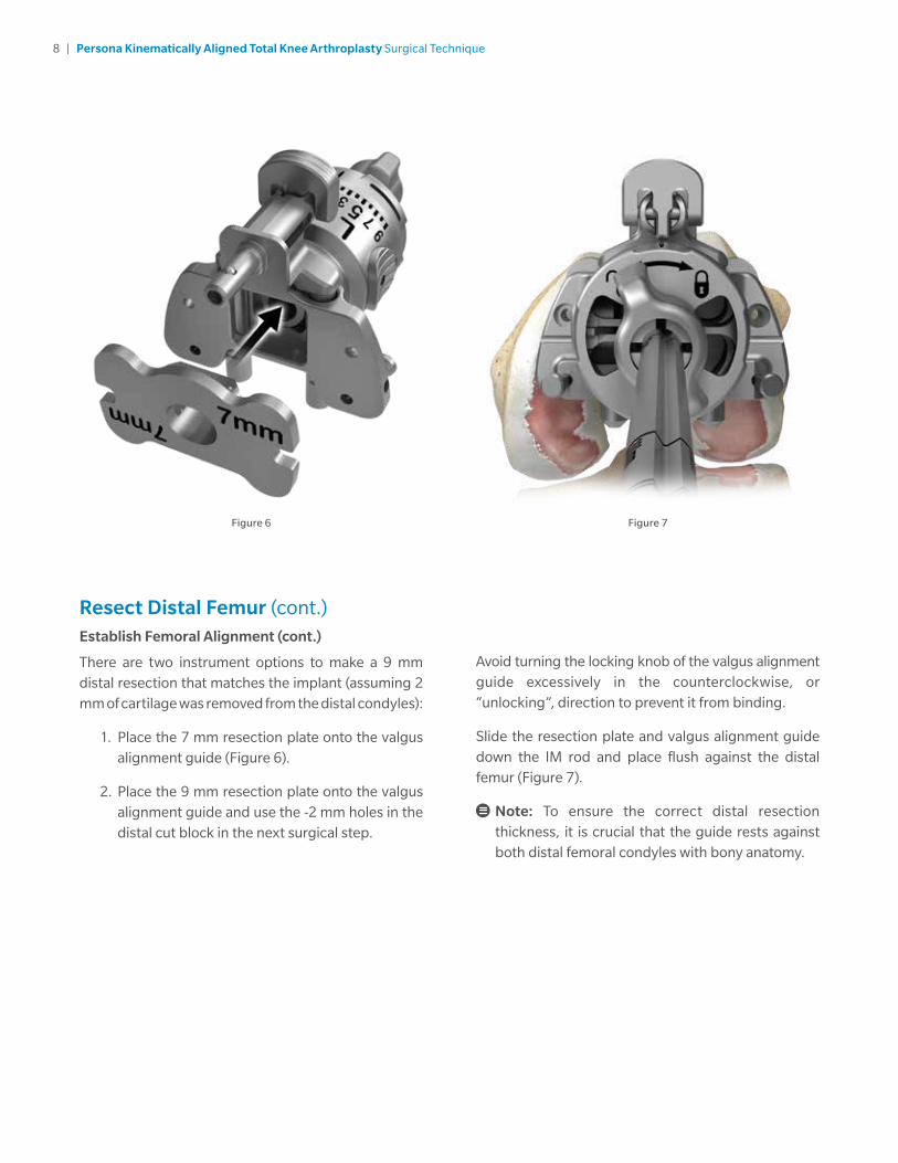
Resect Distal Femur (cont.)Establish Femoral Alignment (cont.)
There are two instrument options to make a 9 mm distal resection that matches the implant (assuming 2 mm of cartilage was removed from the distal condyles):
1. Place the 7 mm resection plate onto the valgus alignment guide (Figure 6).
2. Place the 9 mm resection plate onto the valgus alignment guide and use the -2 mm holes in the distal cut block in the next surgical step.
Avoid turning the locking knob of the valgus alignment guide excessively in the counterclockwise, or “unlocking”, direction to prevent it from binding.
Slide the resection plate and valgus alignment guide down the IM rod and place flush against the distal femur (Figure 7).
Note: To ensure the correct distal resection thickness, it is crucial that the guide rests against both distal femoral condyles with bony anatomy.

9 | Persona Kinematically Aligned Total Knee Arthroplasty Surgical Technique
Figure 8 Figure 9
Resect Distal Femur (cont.)Establish Femoral Alignment (cont.)
To restore the native proximal/distal (P/D) position and varus/valgus (V/V) angle of the distal femoral joint line, set the valgus angle on the adjustable valgus alignment guide by pressing the button and rotating the dial to the appropriate left or right valgus angle from 0 to 9 (Figure 8), until both of the feet are touching the femoral condyles (Figure 9).
10 | Persona Kinematically Aligned Total Knee Arthroplasty Surgical Technique
Figure 10 Figure 12a
Figure 12bFigure 11
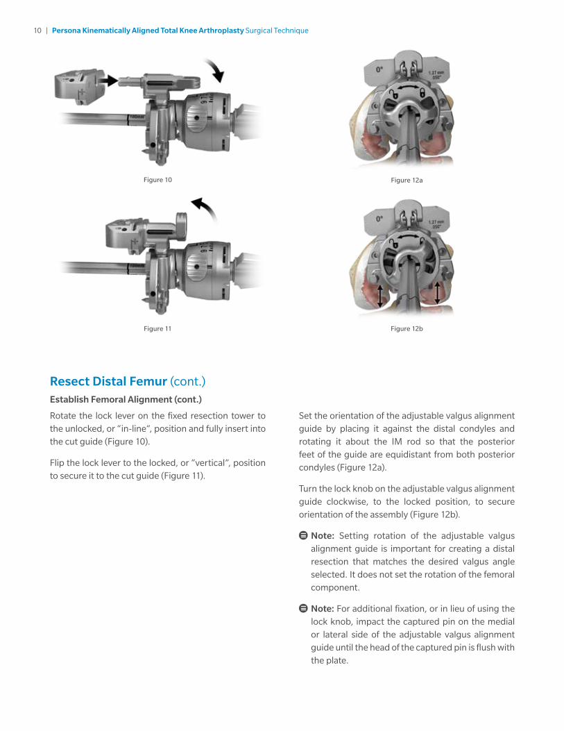
Resect Distal Femur (cont.)Establish Femoral Alignment (cont.)
Rotate the lock lever on the fixed resection tower to the unlocked, or “in-line”, position and fully insert into the cut guide (Figure 10).
Flip the lock lever to the locked, or “vertical”, position to secure it to the cut guide (Figure 11).
Set the orientation of the adjustable valgus alignment guide by placing it against the distal condyles and rotating it about the IM rod so that the posterior feet of the guide are equidistant from both posterior condyles (Figure 12a).
Turn the lock knob on the adjustable valgus alignment guide clockwise, to the locked position, to secure orientation of the assembly (Figure 12b).
Note: Setting rotation of the adjustable valgus alignment guide is important for creating a distal resection that matches the desired valgus angle selected. It does not set the rotation of the femoral component.
Note: For additional fixation, or in lieu of using the lock knob, impact the captured pin on the medial or lateral side of the adjustable valgus alignment guide until the head of the captured pin is flush with the plate.

11 | Persona Kinematically Aligned Total Knee Arthroplasty Surgical Technique
Figure 13 Figure 14
Resect Distal Femur (cont.)Resect Distal Femur
Verify that the adjustable valgus alignment guide is set to the proper side (left or right) and angle.
Note: If using the adjustable resection tower, make sure the setting is at ‘0’. If unsure of the depth setting, rotate the dial clockwise until a “click” is felt. This occurs when the dial moves from the ‘4’ setting to the ‘0’ setting. The bold ‘0’ will be visible on the dial and the line will be aligned with the ‘0’ mark along the shaft
Insert a trocar tipped drill pin through each of the standard pin holes marked ‘0’ on the anterior surface of the cut guide (Figure 13).
Note: If the 7 mm resection plate was used, leave the cut guide in the holes marked ‘0’. If the 9 mm resection plate was used, move the cut guide to the holes marked ‘-2’.
Flip the lock lever on the fixed resection tower to the unlocked, or “in-line”, position and remove the IM rod and assembled distal resection instrumentation leaving only the cut guide attached to the femur (Figure 14).
Note: Additional 2 mm adjustments may be made by using the sets of holes marked -2, +2, and +4. These sets of holes indicate, in millimeters, the amount of additional bone resection each will yield relative to the resection setting on the resection tower (where ‘0’ represents 7 mm when the 7 mm resection plate is used).
Insert the resection guide (angel wing) into the cut slot of the cut guide to verify the depth of resection.

12 | Persona Kinematically Aligned Total Knee Arthroplasty Surgical Technique
Resect Distal Femur (cont.)Resect Distal Femur (cont.)
Insert a trocar tipped drill pin through at least one of the locking, or oblique, pin holes in the cut guide to further secure the cut guide to the femur (Figure 15a).
Using a 1.27 mm (0.050 inch) oscillating saw blade through the cut slot in the cut guide, resect the distal femur.
If desired, the bone resection can be made from the top (most distal) surface of the cut guide (Figure 15b).
Figure 15a
Figure 15b
Figure 15c
The top surface of the cut guide is 4 mm from the cut slot. Therefore, if cutting from the top surface, the position of the cut guide must be adjusted by moving the cut guide from the trocar tipped drill pins through the ‘0’ holes and reinserting the cut guide onto the trocar tipped drill pins through the holes marked ‘+4’ (Figure 15c). Insert a trocar tipped drill pin through at least one of the locking, or oblique, pin holes in the cut guide to further secure the cut guide to the femur prior to resecting the femur.

13 | Persona Kinematically Aligned Total Knee Arthroplasty Surgical Technique
Figure 16
Resect Distal Femur (cont.)Measure and Record the Thickness of the Distal Femoral Resections
Use the femur caliper to measure the thickness of the distal medial and lateral femoral resections at the location where the distal cut paddles were touching and record these measurements (Figure 16).
Note: In order to restore the native distal femoral joint line and match the 9 mm thickness of the CR femoral component, the resection thickness of the condyles should measure approximately 6 mm thick (compensating for the approximate 1 mm thickness of the saw blade). If the initial resection is 1 mm or less than the desired thickness, place the oscillating blade back through the distal cut guide and resect additional distal femur. If the resection is 2 mm less than the desired thickness, move the distal cut block back 2 mm (move to the +2 holes in the cut guide) and resect additional bone.
Note: The flatness of the distal femoral resection is critical to ensuring adequate contact between the porous femoral implant and the bone. If using a porous femoral implant, evaluate the flatness of the resection prior to sizing and modify the cut as necessary so that it is completely flat.
Remove all pins and the cut guide.

14 | Persona Kinematically Aligned Total Knee Arthroplasty Surgical Technique
Figure 17b
Figure 17a Figure 18
Size Femur and Establish External RotationAssemble the posterior referencing sizer boom with the posterior referencing sizer (Figures 17a-17b).
Set the femoral rotation to 0 degrees by holding the body (silver portion) of the sizer in one hand, positioning the opposite index finger behind the “L” or “R” with the thumb over the “L” or “R” and, squeeze to adjust (Figure 18).
Note: Remove any osteophytes that interfere with instrument positioning.

15 | Persona Kinematically Aligned Total Knee Arthroplasty Surgical Technique
Figure 19 Figure 20
Size Femur and Establish External Rotation (cont.)
Apply the sizer so that the flat surface of the sizer is flush against the resected surface of the distal femur and the feet of the sizer are flush against the posterior condyles. Center the sizer mediolaterally.
While holding the sizer in place and if necessary, secure the sizer to the femur using 25 mm X 2.5 mm female hex screws (Figure 19) in one or both of the holes on the lower portion of the sizer to help draw the sizer adjacent to the distal femur, particularly in MIS situations.
Note: Use of 48 mm screws in the region is not recommended due to potential perforation through the posterior femoral condyles.
Note: Do not impact the sizer onto the femur.
Slightly extend the knee and retract soft tissues to expose the anterior femoral cortex. Clear any soft tissue from the anterior cortex. Ensure that the leg is in less than 90 degrees of flexion (70–80 degrees).
This will decrease the tension of the patellar tendon to facilitate placement of the sizing boom. The position of the boom tip approximates the proximal position of the anterior flange of the femoral component. The sizing boom can be rotated to facilitate insertion under the soft tissue envelope. A palpable indication, as well as size markings on the top portion of the sizing boom, ensures that the sizing boom is rotated to the correct position.
Note: Positioning the sizing boom tip on the “high” part of the femur by lateralizing the location of the sizing boom tip can often lessen the likelihood of notching the femur.
After the posterior referencing sizing boom is appropriately positioned, read the femoral size directly from the sizer, between the arrowed engraved lines on the sizing tower (Figure 20). There are 10 sizes labeled 3 through 12.

16 | Persona Kinematically Aligned Total Knee Arthroplasty Surgical Technique
Figure 21 Figure 22
Size Femur and Establish External Rotation (cont.)
The same size markings are present on the anterior surface of the sizing boom and approximate the proximal position of the anterior flange of the femoral component when telescoped to the same size that has been determined by the vertical A/P sizing tower (Figure 21).
The holes in the midline of the A/P portion of the sizer are used to drill 3.2 mm holes for pegs on the posterior referencing 4-in-1 femoral cut guides. Drill through the posterior referencing sizer’s holes while being careful not to disturb the position of the sizer during drilling (Figure 22).
Select the posterior referencing 4-in-1 femoral cut guide that matches the femoral component size indicated on the posterior referencing femoral sizer.
Note: These instruments make a 9 mm resection of the posterior femoral condyles including the blade thickness, regardless of the size of the femoral component.
17 | Persona Kinematically Aligned Total Knee Arthroplasty Surgical Technique
Figure 23 Figure 24
Complete Femoral Resections and Measure Thicknesses
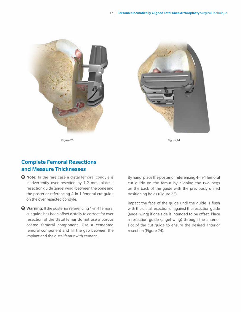
Note: In the rare case a distal femoral condyle is inadvertently over resected by 1-2 mm, place a resection guide (angel wing) between the bone and the posterior referencing 4-in-1 femoral cut guide on the over resected condyle.
Warning: If the posterior referencing 4-in-1 femoral cut guide has been offset distally to correct for over resection of the distal femur do not use a porous coated femoral component. Use a cemented femoral component and fill the gap between the implant and the distal femur with cement.
By hand, place the posterior referencing 4-in-1 femoral cut guide on the femur by aligning the two pegs on the back of the guide with the previously drilled positioning holes (Figure 23).
Impact the face of the guide until the guide is flush with the distal resection or against the resection guide (angel wing) if one side is intended to be offset. Place a resection guide (angel wing) through the anterior slot of the cut guide to ensure the desired anterior resection (Figure 24).

18 | Persona Kinematically Aligned Total Knee Arthroplasty Surgical Technique
Complete Femoral Resections and Measure Thicknesses (cont.)
If there is a risk of unacceptable notching of the anterior cortex, use the slaphammer to axially remove the cut guide (Figures 25–26). Place the next larger-sized femoral cut guide on the femur and recheck the anterior resection level with the resection guide (angel wing).
Figure 25 Figure 26
Note: Utilizing the posterior referencing instruments will not alter the depth of the posterior femoral resection.

19 | Persona Kinematically Aligned Total Knee Arthroplasty Surgical Technique
Figure 27 Figure 28
Complete Femoral Resections and Measure Thicknesses (cont.)
After final placement of the desired posterior referencing 4-in-1 femoral cut guide, insert 3.2 mm trocar-tipped pins or 3.2 mm headed screws (see List and Description of Screws and Pins) through the oblique holes in the posterior referencing 4-in-1 femoral cut guide (Figure 27).
Note: It is not recommended that the following headed screws are used through the oblique holes of the posterior referencing 4-in-1 femoral cut guides, as the head of the screw may interfere with the saw blade: 00-5791-041-00, 00-5791-043-00, 00-5791-044-00, 00-5061-063-00.
Prior to posterior condylar resection, place a 3/4 inch (~19 mm) osteotome at the bottom of the posterior referencing 4-in-1 femoral cut guide and and draw a line on the tibia (Figure 28).
Note: This line is not intended to be a depth guide, it provides a visual aid for the V/V angle of the proximal tibial resection.
Use a 1.27 mm (.050 inch) thick oscillating saw blade to resect the posterior femoral condyles.

20 | Persona Kinematically Aligned Total Knee Arthroplasty Surgical Technique
Complete Femoral Resections and Measure Thicknesses (cont.)
Measure the thickest portion of the posterior medial and lateral femoral resections with the femur caliper before making the anterior and chamfer cuts (Figure 29), and record these measurements.
In order to match the thickness of the 9 mm Persona CR Femoral Implant, each resection should measure approximately 8 mm thick (compensating for the approximate 1 mm thickness of the saw blade).
If the posterior resection is insufficient, the cut guide can be shifted 2 mm anteriorly by drilling through the two holes marked “2 mm”. Remove the original posterior referencing 4-in-1 femoral cut guide, and place the next smaller-sized posterior referencing 4-in-1 femoral cut guide into the “anteriorized” holes in the femur (Figures 30–31). Downsizing in combination with the anterior shift will leave the anterior resection level unaltered. Verify the final resection levels using the resection guide (angel wing).
Note: If the 2 mm shift holes are to be used, assure that the desired holes on the distal femur are used. The resection guide (angel wing) can be used as final verification of the anticipated anterior and posterior resections.
The shift block can be used to shift the posterior referencing 4-in-1 femoral cut guide 1 mm in the anterior or posterior directions.
Figure 29
Figure 31
Figure 30

21 | Persona Kinematically Aligned Total Knee Arthroplasty Surgical Technique
Figure 32a Figure 32b Figure 32c
Complete Femoral Resections and Measure Thicknesses (cont.)Optional Instruments: Shift Block
Prior to performing the remaining facet cuts with the posterior referencing 4-in-1 femoral cut guide, determine whether the A/P position of the block and external rotation are sufficient. If adjustment is needed, remove the posterior referencing 4-in-1 femoral cut guide from the femur and insert the shift block using the same holes in the distal face of the femur (Figure 32a).
To select the method of adjustment, depress button and rotate the drill guide until the desired face is shown.
If an A/P shift is desired, rotate the guide to the appropriate 1 mm shift face (Figure 32b).
Note: Do not impact or torque the shift block while inserting or drilling.
After making sure the appropriate face is locked in place, drill through the holes that have been selected using a 3.2 mm drill (Figure 32c).
Note: Ensure the shift block is locked in place for an accurate shift.
If additional adjustment with the shift block is desired, remove it from the bone, using an osteotome if necessary, and replace it in the newly drilled holes and repeat the drilling process. Otherwise, place the posterior referencing 4-in-1 femoral cut guide in the newly drilled holes and perform bone resections.
Note: The shift block can be rotated 180 degrees to create new drill holes in the opposite M/L direction while providing the same A/P shift. If a 180 degree rotation is performed, be careful to avoid overlapping previously drilled holes.

22 | Persona Kinematically Aligned Total Knee Arthroplasty Surgical Technique
Figure 33 Figure 34
Complete Femoral Resections and Measure Thicknesses (cont.)
Complete the anterior, posterior chamfer and anterior chamfer resections through the cut slots (Figure 33).
Upon completion of the cuts, use the multi pin puller or pin/screw inserter to remove the oblique pins. Use the slaphammer to remove the cut guide from the femur. Insert slaphammer and rotate 1/4 turn clockwise to engage the locking feature to extract (Figure 34).

23 | Persona Kinematically Aligned Total Knee Arthroplasty Surgical Technique
Locate the A/P Axis of the TibiaTo improve the exposure of the tibial surface, retract the tibia anteriorly. Carefully position the retractor against the posterior cortex of the tibia subperiosteally to prevent neurovascular injury. Retract the patella laterally.
Remove the medial and lateral menisci. Protect and retain the insertion of the posterior cruciate ligament (PCL).
Outline the nearly elliptical boundary of the lateral tibial plateau with a marking pen. Define the A/P axis of the tibia by marking the major axis of the ellipse with an electrocautery or marking pen (Figure 35).
Drill two 3.2 mm holes (one posterior, one anterior), approximately 15-20 mm deep on the centerline of the ellipse (Figure 36).
Note: The holes created by the pins will be used to visualize the A/P axis of the Kinematically Aligned Tibial Component after resecting the proximal tibia.
Figure 36Figure 35

24 | Persona Kinematically Aligned Total Knee Arthroplasty Surgical Technique
Figure 37 Figure 38
Resect Proximal TibiaAssemble Extramedullary (EM) Alignment Guide
Depress and hold the button on the EM distal rod and insert the threaded rod on the EM ankle clamp into the distal rod and release the button. Depress and hold the button on the distal end of the EM proximal tube and insert the EM distal rod into the EM proximal tube and release the button (Figure 37).
Attach the 7 degree tibial cut guide to the EM alignment guide (Figure 38).
1. Lift the lever on the EM proximal tube up.
2. Translate the cut guide onto the top of the EM proximal tube, under the locking cone.
3. Push down the lever on the EM proximal tube to lock the cut guide in place.

25 | Persona Kinematically Aligned Total Knee Arthroplasty Surgical Technique
Resect Proximal Tibia (cont.)Assemble Extramedullary (EM) Alignment Guide (cont.)
The buttons shown in Figure 39 are used to adjust the following: varus/valgus angle of the cut guide, slope of the cut guide, the height of the cut guide. The height adjustment button can be depressed for macro-adjustment or the dial can be rotated for micro-adjustment.
One full rotation of the dial equals 4 mm of height adjustment and 1/4 turn equals 1 mm of height adjustment (Figure 40). Rotating the height adjustment dial clockwise shortens the alignment guide and rotating the dial counterclockwise lengthens the alignment guide.
Figure 39 Figure 40
26 | Persona Kinematically Aligned Total Knee Arthroplasty Surgical Technique
Figure 41 Figure 43
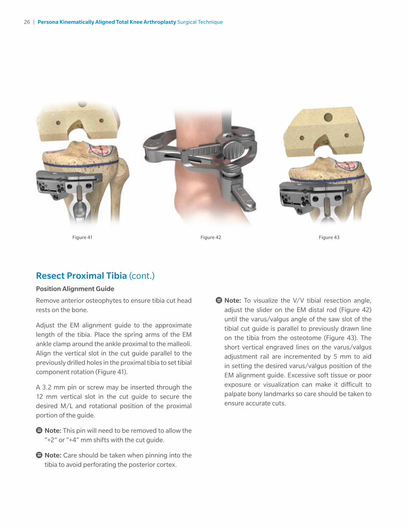
Resect Proximal Tibia (cont.)Position Alignment Guide
Remove anterior osteophytes to ensure tibia cut head rests on the bone.
Adjust the EM alignment guide to the approximate length of the tibia. Place the spring arms of the EM ankle clamp around the ankle proximal to the malleoli. Align the vertical slot in the cut guide parallel to the previously drilled holes in the proximal tibia to set tibial component rotation (Figure 41).
A 3.2 mm pin or screw may be inserted through the 12 mm vertical slot in the cut guide to secure the desired M/L and rotational position of the proximal portion of the guide.
Note: This pin will need to be removed to allow the “+2” or “+4” mm shifts with the cut guide.
Note: Care should be taken when pinning into the tibia to avoid perforating the posterior cortex.
Note: To visualize the V/V tibial resection angle, adjust the slider on the EM distal rod (Figure 42) until the varus/valgus angle of the saw slot of the tibial cut guide is parallel to previously drawn line on the tibia from the osteotome (Figure 43). The short vertical engraved lines on the varus/valgus adjustment rail are incremented by 5 mm to aid in setting the desired varus/valgus position of the EM alignment guide. Excessive soft tissue or poor exposure or visualization can make it difficult to palpate bony landmarks so care should be taken to ensure accurate cuts.
Figure 42
27 | Persona Kinematically Aligned Total Knee Arthroplasty Surgical Technique
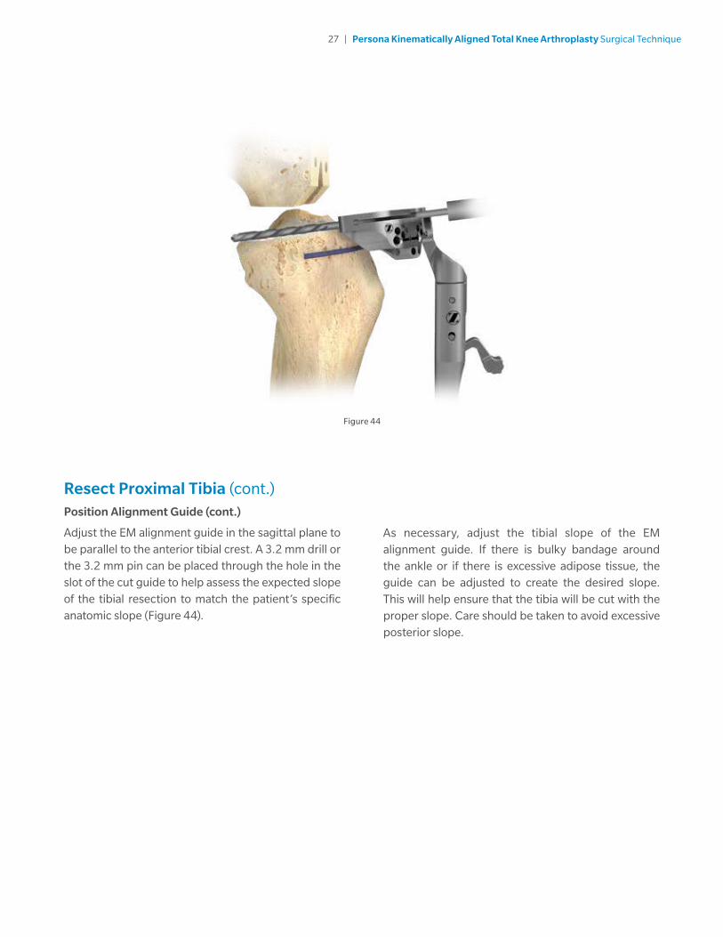
Resect Proximal Tibia (cont.)Position Alignment Guide (cont.)
Adjust the EM alignment guide in the sagittal plane to be parallel to the anterior tibial crest. A 3.2 mm drill or the 3.2 mm pin can be placed through the hole in the slot of the cut guide to help assess the expected slope of the tibial resection to match the patient’s specific anatomic slope (Figure 44).
Figure 44
As necessary, adjust the tibial slope of the EM alignment guide. If there is bulky bandage around the ankle or if there is excessive adipose tissue, the guide can be adjusted to create the desired slope. This will help ensure that the tibia will be cut with the proper slope. Care should be taken to avoid excessive posterior slope.
28 | Persona Kinematically Aligned Total Knee Arthroplasty Surgical Technique
Figure 45 Figure 46
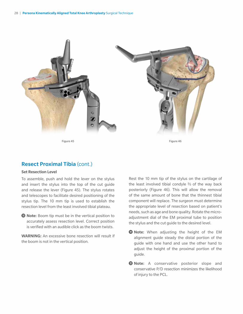
Resect Proximal Tibia (cont.)Set Resection Level
To assemble, push and hold the lever on the stylus and insert the stylus into the top of the cut guide and release the lever (Figure 45). The stylus rotates and telescopes to facilitate desired positioning of the stylus tip. The 10 mm tip is used to establish the resection level from the least involved tibial plateau.
Note: Boom tip must be in the vertical position to accurately assess resection level. Correct position is verified with an audible click as the boom twists.
WARNING: An excessive bone resection will result if the boom is not in the vertical position.
Rest the 10 mm tip of the stylus on the cartilage of the least involved tibial condyle 2/3 of the way back posteriorly (Figure 46). This will allow the removal of the same amount of bone that the thinnest tibial component will replace. The surgeon must determine the appropriate level of resection based on patient’s needs, such as age and bone quality. Rotate the micro-adjustment dial of the EM proximal tube to position the stylus and the cut guide to the desired level.
Note: When adjusting the height of the EM alignment guide steady the distal portion of the guide with one hand and use the other hand to adjust the height of the proximal portion of the guide.
Note: A conservative posterior slope and conservative P/D resection minimizes the likelihood of injury to the PCL.

29 | Persona Kinematically Aligned Total Knee Arthroplasty Surgical Technique
Resect Proximal Tibia (cont.)Set Resection Level (cont.)
A resection guide (angel wing) can be placed through the cut slot on the cut guide, to verify the desired level and slope of the resection (Figure 47). Insert a 3.2 mm trocar tipped pin through one of the “0” holes in the cut guide with the pin/screw inserter. Ensure the cut guide is flush to the bone and not impeded by soft tissues before making the cut.
Insert a second trocar tipped pin through the other “0” hole in the cut guide with the pin/screw inserter (Figure 48). Remove the stylus by pushing the lever on the side of the stylus and remove.
The entire EM alignment guide can be left in place for additional stability during resection. Optionally, the EM alignment guide can be removed by lifting the lever on the EM proximal tube up to the open position, translating the EM alignment guide anteriorly while leaving the cut guide in place (Figure 49). If the EM alignment guide has been removed, additional 2 mm adjustments may be made by shifting the cut guide to the sets of holes marked “+2”, and “+4”. The markings on the cut guide indicate, in millimeters, the amount of additional bone resection relative to the standard tibial resection set by the cut guide and stylus. If a pin or screw was inserted into the 12 mm vertical slot, it will need to be removed to make the 2 mm adjustments.
Figure 47
Figure 48
Figure 49

30 | Persona Kinematically Aligned Total Knee Arthroplasty Surgical Technique
Figure 50 Figure 51
Resect Proximal Tibia (cont.)Set Resection Level (cont.)
Once the resection level has been determined, insert a 3.2 mm trocar tipped pin in the oblique hole indicated by a lock pin symbol, to further secure the cut guide (Figures 50–51). If a pin or screw was inserted into the 12 mm vertical slot, then a pin through the oblique hole may not be needed for secure fixation.
Note: The patellar tendon may be located behind the lateral side of the cut guide due to the patellar tendon relief cutout on the cut guide. Be careful to avoid cutting the patellar tendon when resecting the tibia.
31 | Persona Kinematically Aligned Total Knee Arthroplasty Surgical Technique
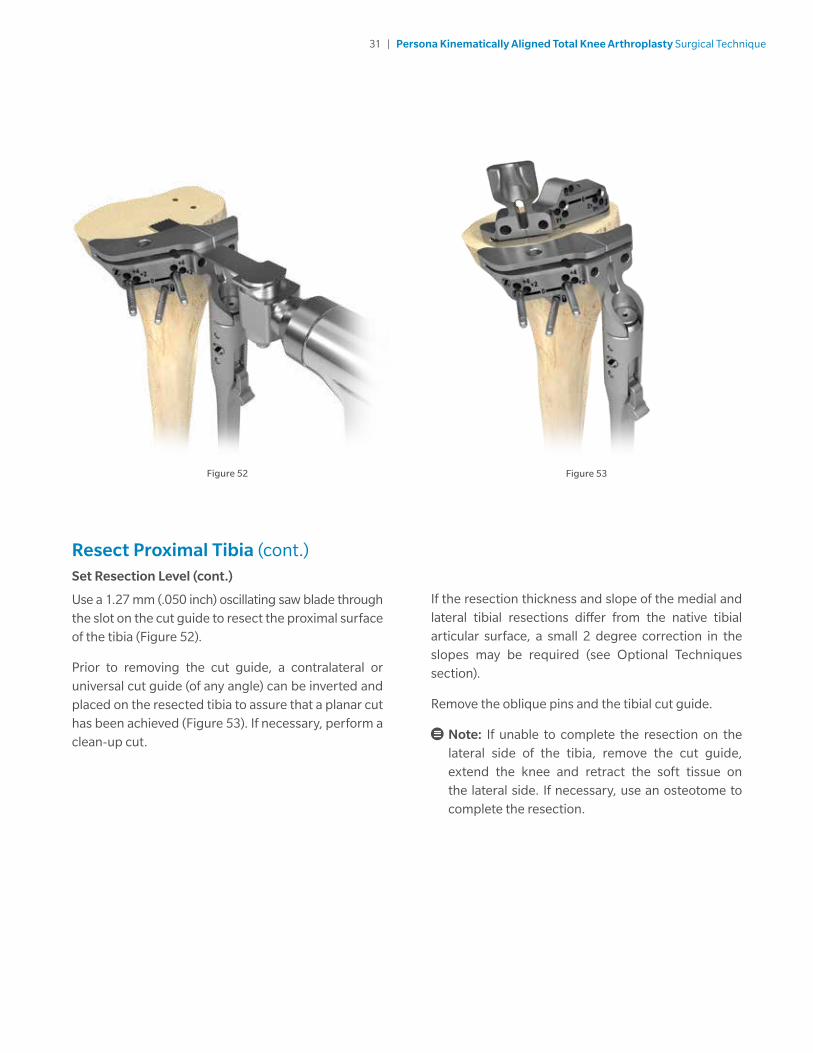
Resect Proximal Tibia (cont.)Set Resection Level (cont.)
Use a 1.27 mm (.050 inch) oscillating saw blade through the slot on the cut guide to resect the proximal surface of the tibia (Figure 52).
Prior to removing the cut guide, a contralateral or universal cut guide (of any angle) can be inverted and placed on the resected tibia to assure that a planar cut has been achieved (Figure 53). If necessary, perform a clean-up cut.
Figure 52 Figure 53
If the resection thickness and slope of the medial and lateral tibial resections differ from the native tibial articular surface, a small 2 degree correction in the slopes may be required (see Optional Techniques section).
Remove the oblique pins and the tibial cut guide.
Note: If unable to complete the resection on the lateral side of the tibia, remove the cut guide, extend the knee and retract the soft tissue on the lateral side. If necessary, use an osteotome to complete the resection.
32 | Persona Kinematically Aligned Total Knee Arthroplasty Surgical Technique
Figure 54
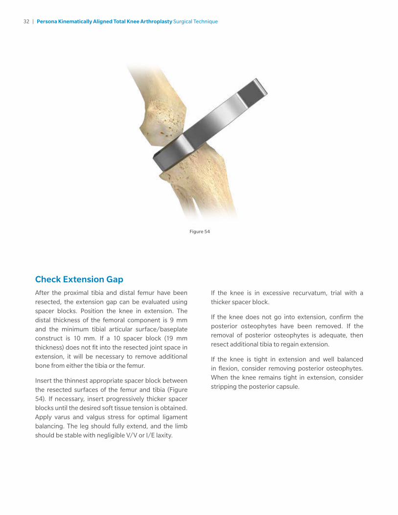
Check Extension GapAfter the proximal tibia and distal femur have been resected, the extension gap can be evaluated using spacer blocks. Position the knee in extension. The distal thickness of the femoral component is 9 mm and the minimum tibial articular surface/baseplate construct is 10 mm. If a 10 spacer block (19 mm thickness) does not fit into the resected joint space in extension, it will be necessary to remove additional bone from either the tibia or the femur.
Insert the thinnest appropriate spacer block between the resected surfaces of the femur and tibia (Figure 54). If necessary, insert progressively thicker spacer blocks until the desired soft tissue tension is obtained. Apply varus and valgus stress for optimal ligament balancing. The leg should fully extend, and the limb should be stable with negligible V/V or I/E laxity.
If the knee is in excessive recurvatum, trial with a thicker spacer block.
If the knee does not go into extension, confirm the posterior osteophytes have been removed. If the removal of posterior osteophytes is adequate, then resect additional tibia to regain extension.
If the knee is tight in extension and well balanced in flexion, consider removing posterior osteophytes. When the knee remains tight in extension, consider stripping the posterior capsule.
33 | Persona Kinematically Aligned Total Knee Arthroplasty Surgical Technique
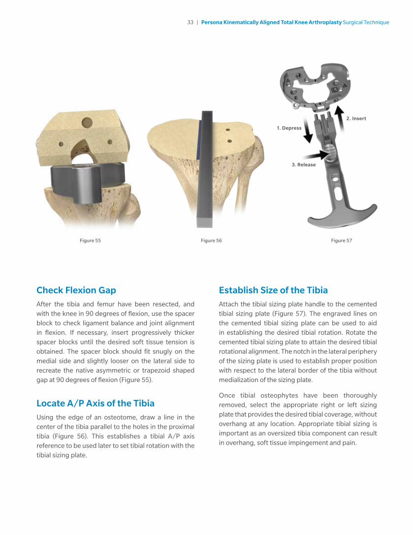
Check Flexion GapAfter the tibia and femur have been resected, and with the knee in 90 degrees of flexion, use the spacer block to check ligament balance and joint alignment in flexion. If necessary, insert progressively thicker spacer blocks until the desired soft tissue tension is obtained. The spacer block should fit snugly on the medial side and slightly looser on the lateral side to recreate the native asymmetric or trapezoid shaped gap at 90 degrees of flexion (Figure 55).
Locate A/P Axis of the TibiaUsing the edge of an osteotome, draw a line in the center of the tibia parallel to the holes in the proximal tibia (Figure 56). This establishes a tibial A/P axis reference to be used later to set tibial rotation with the tibial sizing plate.
Establish Size of the TibiaAttach the tibial sizing plate handle to the cemented tibial sizing plate (Figure 57). The engraved lines on the cemented tibial sizing plate can be used to aid in establishing the desired tibial rotation. Rotate the cemented tibial sizing plate to attain the desired tibial rotational alignment. The notch in the lateral periphery of the sizing plate is used to establish proper position with respect to the lateral border of the tibia without medialization of the sizing plate.
Once tibial osteophytes have been thoroughly removed, select the appropriate right or left sizing plate that provides the desired tibial coverage, without overhang at any location. Appropriate tibial sizing is important as an oversized tibia component can result in overhang, soft tissue impingement and pain.
Figure 55 Figure 56 Figure 57
2. Insert
1. Depress
3. Release

34 | Persona Kinematically Aligned Total Knee Arthroplasty Surgical Technique
Figure 58 Figure 59
Establish Size of the Tibia (cont.)
When the desired tibial rotation and position have been attained, secure the cemented tibial sizing plate by placing 25 mm x 3.2 mm (2.5 mm female hex) screws or 25 mm x 3.2 mm short head holding pins in the medial and lateral holes near the PCL cutout of the cemented tibial sizing plate (Figure 58). The remaining adjunct fixation holes shown on the surface of the cemented tibial sizing plate can be used if necessary. If the cemented tibial sizing plate is to be used as a provisional in later steps, male-headed screws/ pins used in these holes must be removed prior to using the tibial articular surface provisionals (TASPs) (Figure 59). Ensure that the cemented tibial sizing plate remains in the proper position when securing it to the bone. Remove the tibial sizing plate handle from the cemented tibial sizing plate.
Note: Do not use 48 mm screws for cemented tibial sizing plate fixation. 48 mm screws are not recommended due to potential bone perforation.
Note: Do not impact, lever, or pry the tibial sizing plate handle; this instrument is designed for alignment purposes only.
Note: If using a screw through the anterior medial hole on the periphery of the cemented tibial sizing plate, ensure that the cemented tibial sizing plate remains in the desired position and does not lift off posteriorly.

35 | Persona Kinematically Aligned Total Knee Arthroplasty Surgical Technique
Initial Trial ReductionIn this step, an initial trial reduction is performed to check component position, patellar tracking, range-of-motion (ROM), and joint stability.
Note: Reference the orientation and size etched and/or engraved markings to identify the correct provisional.
Assemble the femoral CR impactor pad to the femoral inserter/extractor. Hold the femoral inserter/extractor with the handle in the open position and insert the femoral CR impactor pad, aligning the “CR” on the femoral CR impactor pad with the arrow on the femoral inserter/extractor (Figure 60). The femoral CR impactor pad is keyed, so the femoral CR impactor pad may have to be rotated while placing and aligning the femoral CR impactor pad onto the femoral inserter/extractor.
Figure 60 Figure 61
Femoral sizes 3 through 11 are provided in two profiles, standard and narrow. The size 3 through 11 standard femoral provisionals have intermittent cutouts around the periphery, with the inner dimension representing the outer profile of the narrow femoral implant and the outer dimension representing the outer profile of the standard femoral implant (Figure 61). Femoral size 12 is provided in one profile, standard and does not have intermittent cutouts. Care should be taken to use the appropriate standard or narrow implant as is related to side (left or right) and size based on the provisional fit and ROM provided during the trialing phase.
Note: Do not impact the anterior flange of the CR femoral provisional, as this may damage the provisional. Do not impact the medial or lateral aspects or the release lever of the femoral inserter/extractor.

36 | Persona Kinematically Aligned Total Knee Arthroplasty Surgical Technique
Initial Trial Reduction (cont.)
Remove any posterior osteophytes or overhanging bone on the femur to facilitate maximum knee flexion. Attach the femoral inserter/extractor to the correct CR femoral provisional by inserting the hook on the femoral inserter/extractor arm into the anterior notch in the CR femoral provisional and close the handle on the femoral inserter/extractor to secure the CR femoral provisional (Figure 62).
Place the correct CR femoral provisional onto the femur in the desired medial/lateral position. Impact the end of the femoral inserter/extractor handle to fully seat the CR femoral provisional onto the femur (Figure 63).
Note: Be sure that soft tissue is not trapped beneath the provisionals. Impact until fully seated.
To remove the femoral inserter/extractor from the CR femoral provisional, pinch the release lever while pulling out/down (Figure 63). Alternatively, if the CR femoral provisional is placed on the femur by hand, the femoral inserter/extractor handle must be in the closed and locked position prior to engaging the CR femoral provisional. Then the femoral inserter/extractor can be used to impact the provisional onto the femur. For additional fixation of the fully seated provisional, insert the 25 mm x 3.2 mm screw (2.5 mm female hex) with the 2.5 mm male hex driver through the hole in the lateral anterior flange of the CR femoral provisional (Figure 64).
Note: If trialing with TASP leave femoral provisional in place until trialing is complete.
Figure 62
Figure 63
Figure 64

37 | Persona Kinematically Aligned Total Knee Arthroplasty Surgical Technique
Initial Trial Reduction (cont.)
With the knee in extension, ensure that the femoral provisional is flush against the resected distal surface of the femur on the medial condyle. Retract the lateral side and check to make sure it is flush distally and on the lateral side.
Note: If the distal cut was inadvertently over resected and a resection guide (angel wing) was used behind the posterior referencing 4-in-1 femoral cut guide, the femoral provisional may not sit flush on both sides.
If patella resurfacing has been performed, insert the appropriate patella provisional during the trialing phase.

38 | Persona Kinematically Aligned Total Knee Arthroplasty Surgical Technique
Figure 65 Figure 66
Initial Trial Reduction (cont.)Tibial Articular Surface Provisional (TASP) Assembly
The TASP consists of three parts: a TASP bottom, a TASP shim, and a TASP top. Select the TASP bottom that matches the cemented tibial sizing plate or tibial base plate implant. Select the TASP top that mates with both the TASP bottom and the femoral provisional or component as marked on the anterior face of the TASP top (Figure 65). In addition to the markings on the parts, the same colors are used for the mating TASP tops and bottoms. Axially align the pin slots on the TASP top with the pins on the TASP bottom during assembly as these parts must be assembled before the TASP shim can be used (Figure 66). Select the set of TASP shims that match the selected tibial implant size.
Note: There are two TASP bottom thicknesses +0 mm and +6 mm. Use +0 mm bottom for 10-14 mm constructs and the +6 mm bottom for 16-20 mm constructs.
Note: TASP bottom pins are offset to prevent assembly of left TASP tops on right TASP bottoms and vice versa.
Note: As shown on the anterior face of the TASP top, confirm the correct constraint, femoral compatibility, tibial size, and side.
Note: Apply gentle manual pressure without impacting the TASP construct with either a mallet or hand. The TASP construct includes the TASP top, bottom, shim, and tibial sizing plate handle.
Note: If using the cemented tibial sizing plate during the trialing phase, please ensure that the necessary male-headed screws/pins are removed from the anterior surface of the cemented tibial sizing plate to avoid interference and potential damage to the TASP.
39 | Persona Kinematically Aligned Total Knee Arthroplasty Surgical Technique
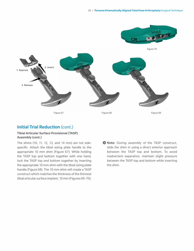
Initial Trial Reduction (cont.)Tibial Articular Surface Provisional (TASP) Assembly (cont.)
The shims (10, 11, 12, 13, and 14 mm) are not side-specific. Attach the tibial sizing plate handle to the appropriate 10 mm shim (Figure 67). While holding the TASP top and bottom together with one hand, lock the TASP top and bottom together by inserting the appropriate 10 mm shim with the tibial sizing plate handle (Figure 68). The 10 mm shim will create a TASP construct which matches the thickness of the thinnest tibial articular surface implant, 10 mm (Figures 69–70).
Note: During assembly of the TASP construct, slide the shim in using a direct anterior approach between the TASP top and bottom. To avoid inadvertent separation, maintain slight pressure between the TASP top and bottom while inserting the shim.
Figure 67 Figure 68 Figure 69
Figure 70
2. Insert1. Depress
3. Release
40 | Persona Kinematically Aligned Total Knee Arthroplasty Surgical Technique
Figure 71 Figure 72
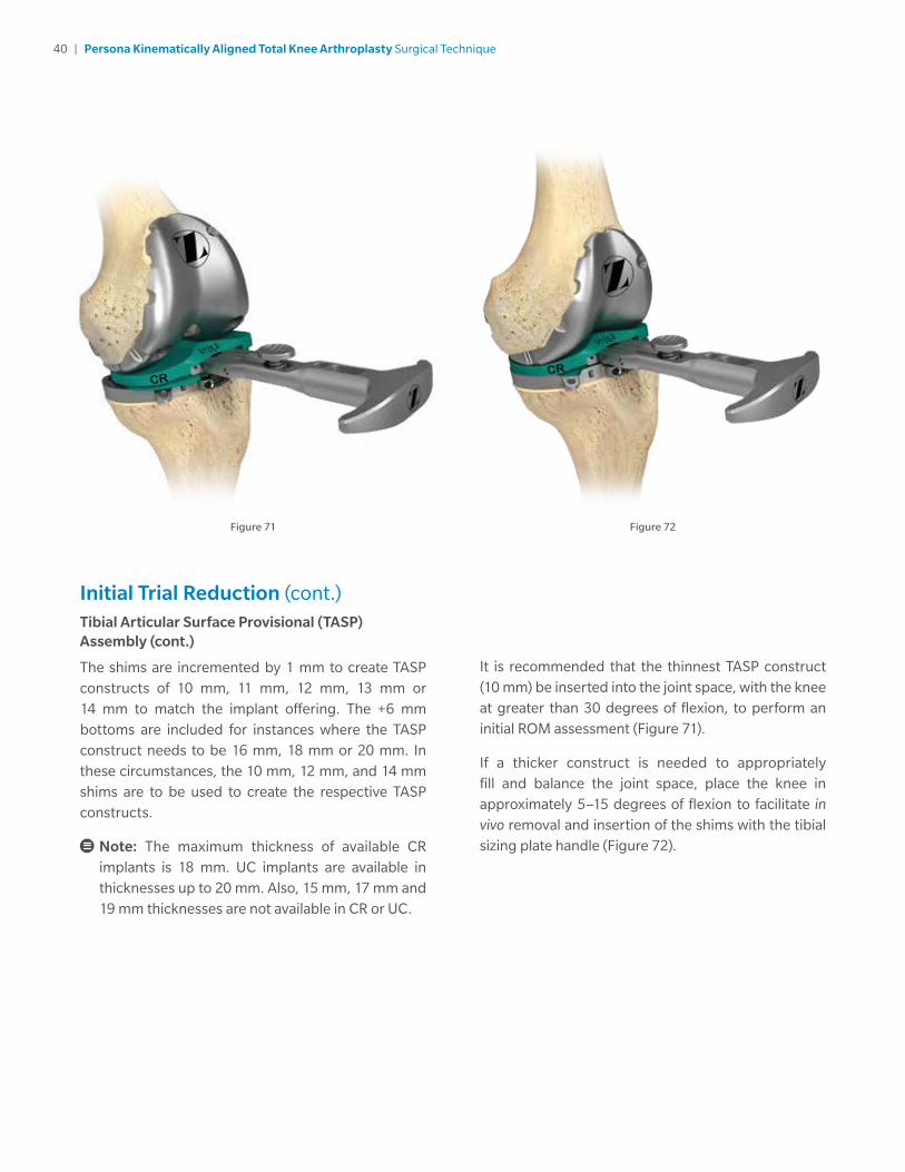
Initial Trial Reduction (cont.)Tibial Articular Surface Provisional (TASP) Assembly (cont.)
The shims are incremented by 1 mm to create TASP constructs of 10 mm, 11 mm, 12 mm, 13 mm or 14 mm to match the implant offering. The +6 mm bottoms are included for instances where the TASP construct needs to be 16 mm, 18 mm or 20 mm. In these circumstances, the 10 mm, 12 mm, and 14 mm shims are to be used to create the respective TASP constructs.
Note: The maximum thickness of available CR implants is 18 mm. UC implants are available in thicknesses up to 20 mm. Also, 15 mm, 17 mm and 19 mm thicknesses are not available in CR or UC.
It is recommended that the thinnest TASP construct (10 mm) be inserted into the joint space, with the knee at greater than 30 degrees of flexion, to perform an initial ROM assessment (Figure 71).
If a thicker construct is needed to appropriately fill and balance the joint space, place the knee in approximately 5–15 degrees of flexion to facilitate in vivo removal and insertion of the shims with the tibial sizing plate handle (Figure 72).
41 | Persona Kinematically Aligned Total Knee Arthroplasty Surgical Technique
TASP Shim/Construct ThicknessAnterior divots in the shim correspond to the overall
construct thickness as shown in the image above.
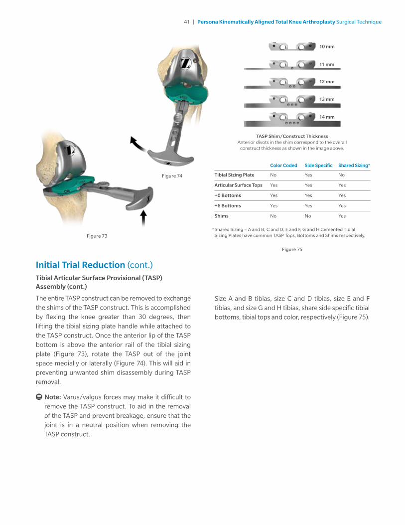
Initial Trial Reduction (cont.)Tibial Articular Surface Provisional (TASP) Assembly (cont.)
The entire TASP construct can be removed to exchange the shims of the TASP construct. This is accomplished by flexing the knee greater than 30 degrees, then lifting the tibial sizing plate handle while attached to the TASP construct. Once the anterior lip of the TASP bottom is above the anterior rail of the tibial sizing plate (Figure 73), rotate the TASP out of the joint space medially or laterally (Figure 74). This will aid in preventing unwanted shim disassembly during TASP removal.
Note: Varus/valgus forces may make it difficult to remove the TASP construct. To aid in the removal of the TASP and prevent breakage, ensure that the joint is in a neutral position when removing the TASP construct.
Figure 73
Figure 74
Figure 75
Size A and B tibias, size C and D tibias, size E and F tibias, and size G and H tibias, share side specific tibial bottoms, tibial tops and color, respectively (Figure 75).
* Shared Sizing – A and B, C and D, E and F, G and H Cemented Tibial Sizing Plates have common TASP Tops, Bottoms and Shims respectively.
Color Coded Side Specific Shared Sizing*
Tibial Sizing Plate No Yes No
Articular Surface Tops Yes Yes Yes
+0 Bottoms Yes Yes Yes
+6 Bottoms Yes Yes Yes
Shims No No Yes
10 mm
11 mm
12 mm
13 mm
14 mm

42 | Persona Kinematically Aligned Total Knee Arthroplasty Surgical Technique
Figure 77
Figure 76
Restore the V/V and I/E LaxityA Kinematically Aligned Knee should fully extend with negligible V/V and I/E laxity (Figure 76). In flexion, there should be slightly more V/V laxity and the tibia should passively I/E rotate approximately ±15 degrees on the femur (Figure 77). Proper Kinematic Alignment restores native limb alignment through measured V/V tibial resection and utilizing a tibial articular surface with the appropriate thickness.
Check ligament stability in extension and in 30, 60, and 90 degrees flexion. In flexion, attempt to distract the joint in the A/P direction.
If the PCL is recessed or becomes deficient intraoperatively, the PCL should be fully resected and the ultracongruent (UC) TASP should be trialed to assure desired ROM and joint stability prior to articular surface implant selection.
When trialing with a CR articular surface and the PCL is retained, posterior soft tissue tightness may occur, resulting in the femur booking open (Figure 78). Should this occur, consider resecting the PCL. If the PCL is resected, a UC insert should be used.
Figure 78

43 | Persona Kinematically Aligned Total Knee Arthroplasty Surgical Technique
Extension
Tight OK Loose
Tight 1 2 3
OK 4 5 6
Loose 7 8 9Fl
exio
n
Flexion/Extension Mismatch Solutions
Note: Ensure that the trials are fully seated appropriately. Soft tissue can get trapped under the femur, causing inadvertent placement of femoral trial in flexion.
1. If the joint is tight in flexion and extension, resecting additional proximal tibial bone or decreasing the thickness of the articular surface may be sufficient to balance the construct.
2. If the joint is tight in flexion but acceptable in extension:
a. Ensure tibial baseplate rotation is correct.
b. Increase the posterior slope of the tibial component (ensuring not to exceed the natural slope of the native tibia).
c. Downsize the femoral component and shift the cuts anterior 1mm with the shift block or 2 mm with the posterior referencing 4-in-1 femoral cut guide 2 mm holes.
d. Release the PCL either by island osteotomy or ligament release (pie crusting technique), both of which lengthen the ligament.
e. Resect the PCL and change to a UC constraint.
3. If the joint is tight in flexion but loose in extension:
a. Ensure tibial baseplate rotation is correct.
b. Increase the posterior slope of the tibial component (ensuring not to exceed the natural slope of the native tibia) and increase the thickness of the articular surface.
c. Downsize the femoral component and shift the cuts 1 mm anteriorly with the shift block, or 2 mm with the posterior referencing 4-in-1 femoral cut guide 2 mm holes and increase the thickness of the articular surface.
4. If the joint is acceptable in flexion but tight in extension:
a. Remove posterior osteophytes and release the posterior capsule from the femur.
b. Resect additional proximal tibial bone with decreased posterior slope and increase the thickness of the articular surface.
c. Recut the distal femoral resection 1 or 2 mm as needed and then recut the anterior and posterior resections with the posterior referencing 4-in-1 femoral cut guide.
5. If the joint is acceptable in flexion and extension, no further modification is necessary.

44 | Persona Kinematically Aligned Total Knee Arthroplasty Surgical Technique
Flexion/Extension Mismatch Solutions (cont.)
6. If the joint is acceptable in flexion but loose in extension:
a. Increase the posterior slope of the tibial component (ensuring not to exceed the natural slope of the native tibia) and increase the thickness of the articular surface.
b. Downsize the femoral component and shift the cuts anterior 1 mm with the shift block or 2 mm with the posterior referencing 4-in-1 femoral cut guide 2 mm holes and increase the thickness of the articular surface.
c. Release the PCL either by island osteotomy or ligament release (pie crusting technique), both of which lengthen the ligament, and increase the thickness of the articular surface.
d. Resect the PCL and change to a UC constraint and increase the thickness of the articular surface.
7. If the joint is loose in flexion but tight in extension:
a. Remove posterior osteophytes, release the posterior capsule from the femur and increase the thickness of the articular surface.
b. Resect additional proximal tibial bone with decreased posterior slope and increase the thickness of the articular surface.
c. Recheck the distal femoral cut and ensure there is not hyperextension of the femoral component. If needed, recut the femur to correct the hyperextension.
Extension
Tight OK Loose
Tight 1 2 3
OK 4 5 6
Loose 7 8 9Fl
exio
n
8. If the joint is loose in flexion and acceptable in extension:
a. Release the posterior capsule from the femur and increase the thickness of the articular surface.
b. Resect additional proximal tibial bone with decreased tibial slope and increase the thickness of the articular surface.
9. If the joint is loose in flexion and extension, increase the thickness of the articular surface.

45 | Persona Kinematically Aligned Total Knee Arthroplasty Surgical Technique
Restore the V/V and I/E Laxity If the knee does not fully extend, insert a 1 mm thinner tibial articular surface provisional or recut the tibia to remove more bone.
Potential solutions to medial/lateral mismatches:
• If the knee is loose medial and tight lateral and all osteophytes have been removed, use the 2 degree valgus recut guide to recut the tibia in valgus and add a 2 mm thicker tibial articular surface provisional.
• If the knee is tight medial and loose lateral and all osteophytes have been removed, use the 2 degree varus recut guide to recut the tibia in varus and add a 2 mm thicker tibial articular surface provisional.
In situations where two options exist to help solve the soft tissue mismatch, the position of the patella or the joint line helps to determine which option to select.
Note: After applying one of these solutions, perform another trial reduction. This will identify any new problem or a variation of the initial problem that may exist.
Flex the knee through a full range of motion and confirm the patellar tracking is optimal.
Warning: To mitigate the occurrence of patella instability postoperatively, assess patellar tracking intraoperatively. If patellar maltracking exists, perform a lateral retinaculum release. If this does not correct the problem, externally rotate the tibial component.
Note: If the TASP construct is used with the femoral and/or tibial implants, contact with bone cement should be avoided to prevent potential damage to the TASP components.
Note: The articular surface inserter should not be used with the TASP.
Note: Use only the tibial sizing plate handle to remove the TASP construct. The use of other instruments may damage or break the TASP.
Drill and Broach TibiaWarning: The Kinematic Alignment (KA) Surgical Technique may only be used with cemented, nonporous Persona Tibial Components without a stem extension. Do not use a stem extension with a Persona Tibial Component when the KA Surgical Technique is used.
The keel of the tibial implant has a unique location for every size; therefore it is critical to select the proper size at this step, before drilling and broaching. Once these subsequent steps have been performed, the size should not be changed. If desired, femoral finishing can be performed in conjunction with provisional trialing at this stage to assure that the desired range of motion and soft tissue balance can be attained with the cemented tibial sizing plate in place prior to drilling and broaching the tibia.

46 | Persona Kinematically Aligned Total Knee Arthroplasty Surgical Technique
Drill and Broach Tibia (cont.)
By hand, place and hold the cemented tibial drill guide on the tibia cemented tibial sizing plate, by first engaging the posterior tabs in the undercuts in the cemented tibial sizing plate and then making sure that the distal anterior portion of the cemented tibial drill guide is flush against the cemented tibial sizing plate (Figures 79a–79b).
Use the cemented tibial drill to drill until the center of the size-specific engraved line on the cemented tibial drill is in line with the top of the cemented tibial drill guide (Figures 80a–80c). After drilling is complete, remove the cemented tibial drill and cemented tibial drill guide.
Note: Insert cemented tibial drill into cemented tibial drill guide prior to starting cemented tibial drill. By hand, hold the cemented tibial drill guide flush against the cemented tibial sizing plate while drilling.
Figure 79b
Figure 79a
Figure 80a
Figure 80b
Figure 80c

47 | Persona Kinematically Aligned Total Knee Arthroplasty Surgical Technique
Figure 80c Figure 81
Figure 82a
Drill and Broach Tibia (cont.)Optional Technique
If desired, the cemented tibial drill stop collar, may be used to aid in drilling to the correct depth. Depress the button on the cemented tibial drill stop collar and slide the cemented tibial drill stop collar to the desired size-specific position on the cemented tibial drill (Figure 81).
Confirm that the correct size is displayed in the cemented tibial drill stop collar window (Figures 82a–82c) and that the cemented tibial drill stop collar is locked on the cemented tibial drill.
Note: Verify that the cemented tibial drill stop collar is locked on the cemented tibial drill by attempting to slide the cemented tibial drill stop collar on the cemented tibial drill by hand. The cemented tibial drill stop collar will make an audible “click” when it locks on the cemented tibial drill.
Note: Insert cemented tibial drill into cemented tibial drill guide prior to drilling.
Figure 82cFigure 82b
48 | Persona Kinematically Aligned Total Knee Arthroplasty Surgical Technique
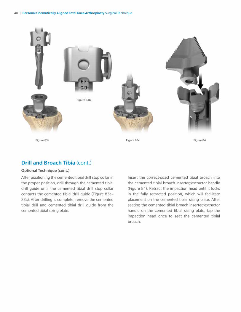
Drill and Broach Tibia (cont.)Optional Technique (cont.)
After positioning the cemented tibial drill stop collar in the proper position, drill through the cemented tibial drill guide until the cemented tibial drill stop collar contacts the cemented tibial drill guide (Figure 83a–83c). After drilling is complete, remove the cemented tibial drill and cemented tibial drill guide from the cemented tibial sizing plate.
Insert the correct-sized cemented tibial broach into the cemented tibial broach inserter/extractor handle (Figure 84). Retract the impaction head until it locks in the fully retracted position, which will facilitate placement on the cemented tibial sizing plate. After seating the cemented tibial broach inserter/extractor handle on the cemented tibial sizing plate, tap the impaction head once to seat the cemented tibial broach.
Figure 83c
Figure 83b
Figure 83a Figure 84
49 | Persona Kinematically Aligned Total Knee Arthroplasty Surgical Technique
Drill and Broach Tibia (cont.)
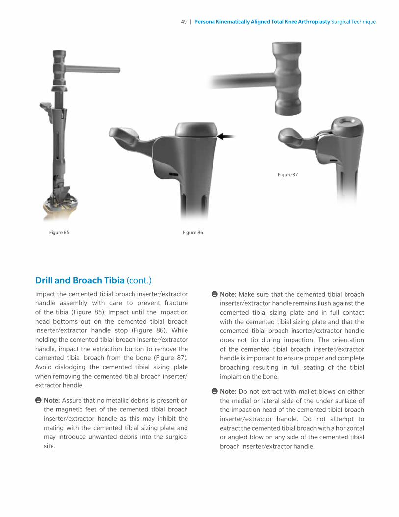
Impact the cemented tibial broach inserter/extractor handle assembly with care to prevent fracture of the tibia (Figure 85). Impact until the impaction head bottoms out on the cemented tibial broach inserter/extractor handle stop (Figure 86). While holding the cemented tibial broach inserter/extractor handle, impact the extraction button to remove the cemented tibial broach from the bone (Figure 87). Avoid dislodging the cemented tibial sizing plate when removing the cemented tibial broach inserter/ extractor handle.
Note: Assure that no metallic debris is present on the magnetic feet of the cemented tibial broach inserter/extractor handle as this may inhibit the mating with the cemented tibial sizing plate and may introduce unwanted debris into the surgical site.
Note: Make sure that the cemented tibial broach inserter/extractor handle remains flush against the cemented tibial sizing plate and in full contact with the cemented tibial sizing plate and that the cemented tibial broach inserter/extractor handle does not tip during impaction. The orientation of the cemented tibial broach inserter/extractor handle is important to ensure proper and complete broaching resulting in full seating of the tibial implant on the bone.
Note: Do not extract with mallet blows on either the medial or lateral side of the under surface of the impaction head of the cemented tibial broach inserter/extractor handle. Do not attempt to extract the cemented tibial broach with a horizontal or angled blow on any side of the cemented tibial broach inserter/extractor handle.
Figure 85
Figure 87
Figure 86

50 | Persona Kinematically Aligned Total Knee Arthroplasty Surgical Technique
Prepare the PatellaIf the surgeon determines that the condition of the patient’s patella is satisfactory, it is not necessary to resurface the patella. The geometry, depth, and length of the patella groove on the femoral component accommodates the unresurfaced patella.
Note: These instruments are designed for onlaying all-poly patella only.
Place the leg in extension, evert the patella to at least 90 degrees. Stabilize the patella, using two inverted towel clips. Incise the soft tissue around the patella down to the insertion of the quadriceps and patella tendons. Before making any bone cuts, determine the maximum thickness of the patella by using the femur caliper to measure the most prominent anterior-to-posterior dimension (Figure 88).
Note: The femur caliper has a tolerance of ± 0.25 mm.
Figure 88
Figure 91
Figure 90
Figure 89
Resect the PatellaPlease refer to the appropriate surgical technique if other patella instrumentation is to be used to resect the patella.
Refer to the sizing chart for patella dimensions (Figure 89). Use a 3.2 mm drill to drill the highest portion of the medial facet perpendicular to the articular surface approximately 12 mm deep centered on the medial sagittal ridge (Figure 90). This acts as a guide for proper medialization of the patella.
Technique Tip: At least 10 mm of bone must remain to ensure that the pegs of the patella implant do not protrude through the anterior surface (Figure 91).
Persona Standard Implant Patella Size & Thickness
26 mm x 7.5 mm* 35 mm x 9.0 mm
29 mm x 8.0 mm 38 mm x 9.5 mm
32 mm x 8.5 mm 41 mm x 10.0 mm
*The 26 mm patella must always be inset. See package insert for complete details.

51 | Persona Kinematically Aligned Total Knee Arthroplasty Surgical Technique
Figure 92 Figure 94
Figure 93
Prepare the Patella (cont.)
Use the patella osteotomy guide with the stylus set for the desired amount of resection. Depress the button on the stylus while twisting to set the stylus at the desired resection level (Figure 92). If the patella is very worn, resect less bone.
Note: Assure that the patella osteotomy guide stylus is referencing the most prominent point on the patella before resecting.
Apply the patella osteotomy guide medially and laterally with the jaws at the osteochondral juncture with the handles of the jig oriented toward the foot. Apply the guide with the jaws parallel to the dorsal surface of the patella, while positioning the patella osteotomy guide stylus over the most prominent point on the patella. Make the resection with a 1.27 mm (.050 inch) thick saw blade (Figure 93). Resect the patella flat so that a smooth surface remains.
Note: To facilitate unlocking the patella osteotomy guide from the patella, apply slight gripping pressure on the handles of the patella osteotomy guide and depress the release lever to unlock the patella osteotomy guide (Figure 94).
Depress collar
Rotate

52 | Persona Kinematically Aligned Total Knee Arthroplasty Surgical Technique
Figure 95 Figure 97
Figure 96
Finish the PatellaUsing the patella sizing template, select the maximum-sized patella that does not overhang, centered over the 3.2 mm drill hole as a reference for proper medialization (Figure 95).
Note: Do not drill through the center hole of the patella sizing template.
Note: Eccentric placement of the patella 3-4 mm medially allows for better patella tracking.
Insert the appropriately-sized patella peg drill guide into the patella clamp in the proper orientation (Figure 96). Place the patella clamp with the patella peg drill guide over the cut surface of the patella, centered slightly toward the medial facet over the 3.2 mm drill hole with the clamp oriented so two of the holes are biased toward the medial side of the patella (Figure 97).

53 | Persona Kinematically Aligned Total Knee Arthroplasty Surgical Technique
Figure 98 Figure 99
Finish the Patella (cont.)
Use the 6.4 mm patella/femoral drill to drill through the 3 peg holes in the patella peg drill guide (Figure 98).
Note: To facilitate unlocking the patella clamp from the patella, apply slight gripping pressure on the handles of the patella clamp and depress the release lever to unlock the patella clamp (Figure 99).

54 | Persona Kinematically Aligned Total Knee Arthroplasty Surgical Technique
CR Femoral Finishing and Final Trial ReductionAfter bone preparation is complete and prior to femoral peg hole preparation, perform a final trial reduction, as described above, to check component position, patellar tracking, range of motion, and joint stability. Once desired medial-lateral placement has been attained, drill the peg holes for size 3 through 12 femoral implants through the CR femoral provisional with the 6.4 mm patella/femoral drill (Figure 100).
If a screw was used to provide adjunct fixation, remove the screw from the anterior flange in the CR femoral provisional.
Note: The slaphammer can be used to remove size 3 through 12 CR femoral provisionals (Figure 101). Rotate the slaphammer a 1/4 turn outward. Alternatively, the femoral inserter/extractor can be re-attached to the CR femoral provisional to remove it from the bone. If necessary, place the round end of the slaphammer in the extraction hole of the femoral inserter/extractor to facilitate removal.
Figure 100
Note: Ensure the shoulder of the drill is seated at the bottom of the femoral provisional counterbore.
Note: Ensure oval hole of the femoral provisional is free of debris prior to inserting slaphammer.
When using the stemmed tibia provisional, assemble the stemmed tibia provisional to the tibial provisional extractor and insert in the prepared tibia bone. For additional fixation of the fully seated provisional, insert two 25 mm x 3.2 mm screws (2.5 mm female hex) with the 2.5 mm male hex driver through the 2 screw fixation holes in the medial and lateral compartments on the stemmed tibia provisional.
If the stemmed tibia provisional was used, assemble the tibial provisional extractor to the stemmed tibia provisional to remove the stemmed tibia provisional prior to implanting the components.
Figure 101

55 | Persona Kinematically Aligned Total Knee Arthroplasty Surgical Technique
Figure 102 Figure 103
Implant Components
Note: Prior to cementing implants remove provisionals and use pulse lavage to remove unwanted debris from the resected bone surfaces and the joint space.
In this step, the final components are implanted, and the tibial articular surface is secured to the implanted tibial baseplate. When using cemented components, it is recommended to use two batches of cement. After the implants have been chosen, make a final check to ensure that all components are compatible. If the resected surfaces of the tibia and/or femur are sclerotic, drill multiple holes with a small drill (2.0 mm – 3.2 mm) to improve cement intrusion. Mix the first batch of cement. Mix the cement following the manufacturer’s guidelines for cement prep including but not limited to mix, work, and set time.
Tibial Plate
Sublux the tibia anteriorly to allow adequate clearance to insert the tibial implant into the prepared bone. Do not apply substances other than bone cement to the tibial implant (i.e. do not dip implant into antibiotics or other substances). Keep the implant clean and free of debris prior to cementing. Place a layer of cement on the underside of the tibial baseplate, around the keel, on the resected tibial surface, and in the tibial IM canal. Assemble the quick connect handle to the tibial impactor head (Figure 102). Unlock collar and hold, insert handle into impactor head, release collar, and rotate handle until an audible “click” is heard. Position the tibial plate onto the tibia and use the tibial impactor to impact it until fully seated (Figure 103). Thoroughly remove any excess cement in a consistent manner. Allow the cement to fully cure before performing a trial range of motion or inserting the articular surface.

56 | Persona Kinematically Aligned Total Knee Arthroplasty Surgical Technique
Figure 104 Figure 106
Figure 105
Implant Components (cont.)Femoral Component
With the knee in 70 –90 degrees of flexion, retract the soft tissue in the desired manner. Place a layer of cement on the underside of the prosthesis and in the holes drilled in the femur. Attach the femoral inserter/extractor to the femoral component (Figure 104). Insert the femoral component onto the distal femur by translating the component laterally until the lateral peg aligns with the drill hole in the lateral femoral condyle. Take care to avoid scratching the implant component surfaces. After the femoral component is placed on the femur and the femoral inserter/extractor is removed, the femoral inserter/extractor can be used to fully seat the implant onto the femur. If this method is used, the femoral inserter/extractor handle must be in the closed and locked position. Ensure that soft tissue is not trapped beneath the implant.
Alternatively, assemble the quick connect handle to the femoral impactor head (Figure 105). Use this assembly to fully seat the femoral implant (Figure 106). Remove retractors, and check the medial and lateral sides to make sure the femoral implant is fully impacted distally. Remove any excess cement in a thorough and consistent manner.
Figure 107

57 | Persona Kinematically Aligned Total Knee Arthroplasty Surgical Technique
Figure 107 Figure 109
Figure 108
Implant Components (cont.)Articular Surface
The articular surface inserter applies both downward and rearward forces to aid in the insertion of the articular surface onto the tibial baseplate. Choose the correct tibial articular surface based on size, side, constraint, and thickness as determined by the trial range of motion. Place the articular surface onto the tibial baseplate. Apply pressure anterior to posterior to properly engage the tibial component and tibial articular surface for final seating. This is necessary to allow the inserter to properly engage the tibial component and tibial articular surface for final seating (Figure 107). Steady the surface of the baseplate with one hand by applying downward pressure near the posterior cruciate cutout. Engage the hook on the articular surface inserter with the mating slot in the front of the baseplate and close the lever with your index finger. This locks the inserter to the tibial plate (Figure 108). Squeeze the handle of the articular surface inserter to seat the articular surface (Figure 109). Open the lever and remove the articular surface inserter.
Note: Do not impact or lever the articular surface inserter tool when it is attached to the tibial plate as this may disrupt the fixation of the tibial plate to the bone and/or cause damage to the implant or instrument. Also, do not impact the articular surface.
Note: Insert an articular surface only once. Never reinsert the same articular surface onto a tibial baseplate.
Alternatively, the articular surface can be locked into the tibial plate as described above, prior to tibial plate implantation. If CR femoral implants are used, the tibial implant should be implanted prior to the femoral implant to facilitate the removal of excess cement from the posterior aspect of the tibia, prior to femoral implantation.
Note: Only in vivo assembly of the ultracongruent articular surface is recommended because the design of the ultracongruent articular surface precludes cement removal from the PCL cutout area at the tibial baseplate/bone interface.

58 | Persona Kinematically Aligned Total Knee Arthroplasty Surgical Technique
Figure 110
Implant Components (cont.)Articular Surface (cont.)
Assemble the quick connect handle to the tibial impactor head. Unlock collar and hold, insert quick connect handle into tibial impactor head, release collar, and rotate handle until an audible “click” is heard. Position the tibial plate/articular surface construct onto the tibia and use the tibial impactor to impact it until fully seated (Figure 110). Thoroughly remove any excess cement in a consistent manner.
To remove an articular surface from the baseplate, engage the hook on the articular surface removal instrument with the mating slot on the front of the baseplate and squeeze the handle to disengage the articular surface from the baseplate. The articular surface removal instrument should not be used for provisional removal.
Note: Do not impact or lever the articular surface extractor tool when it is attached to the tibial plate as this may disrupt the fixation of the tibial plate to the bone and/or cause damage to the implant or instrument.
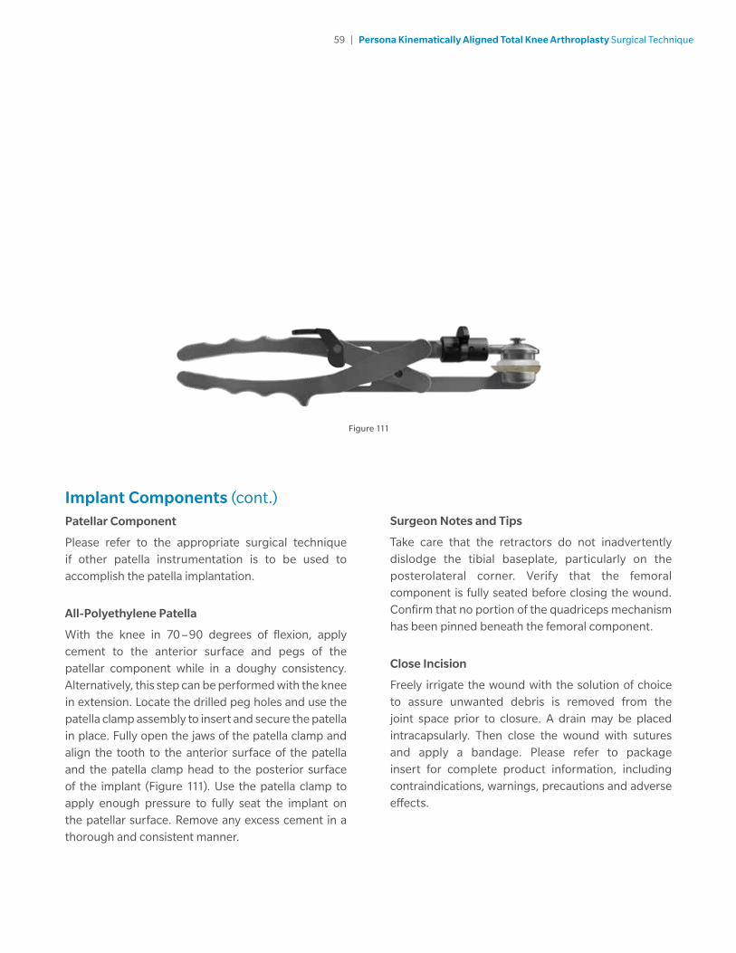
59 | Persona Kinematically Aligned Total Knee Arthroplasty Surgical Technique
Implant Components (cont.)Patellar Component
Please refer to the appropriate surgical technique if other patella instrumentation is to be used to accomplish the patella implantation.
All-Polyethylene Patella
With the knee in 70 –90 degrees of flexion, apply cement to the anterior surface and pegs of the patellar component while in a doughy consistency. Alternatively, this step can be performed with the knee in extension. Locate the drilled peg holes and use the patella clamp assembly to insert and secure the patella in place. Fully open the jaws of the patella clamp and align the tooth to the anterior surface of the patella and the patella clamp head to the posterior surface of the implant (Figure 111). Use the patella clamp to apply enough pressure to fully seat the implant on the patellar surface. Remove any excess cement in a thorough and consistent manner.
Surgeon Notes and Tips
Take care that the retractors do not inadvertently dislodge the tibial baseplate, particularly on the posterolateral corner. Verify that the femoral component is fully seated before closing the wound. Confirm that no portion of the quadriceps mechanism has been pinned beneath the femoral component.
Close Incision
Freely irrigate the wound with the solution of choice to assure unwanted debris is removed from the joint space prior to closure. A drain may be placed intracapsularly. Then close the wound with sutures and apply a bandage. Please refer to package insert for complete product information, including contraindications, warnings, precautions and adverse effects.
Figure 111

60 | Persona Kinematically Aligned Total Knee Arthroplasty Surgical Technique
Figure 112 Figure 113
Optional Techniques2 Degree Valgus Recut Guide
If a 2 degree valgus correction cut is needed, place the valgus recut guide on the resected tibial plateau, aligning with the previously defined A/P axis of the tibia (Figure 112). Once it has been determined that the desired correction cut will be attained, slide the medial portion of the valgus recut guide so it is flush with the medial portion of the tibial cortex to provide a planar recut of the tibia. Affix with 3.2 mm trocar-tipped pins with the pin and screw inserter.
Note: The fixation holes for the valgus recut guide are at oblique angles to improve fixation of the guide.
Perform resection, remove trocar-tipped pins and the valgus recut guide.
2 Degree Varus Recut Guide
If a 2 degree varus correction cut is needed, place the varus recut guide on the resected tibial plateau, aligning with the previously defined A/P axis of the tibia (Figure 113). Once it has been determined that the desired correction cut will be attained, slide the lateral portion of the varus recut guide so it is flush with the lateral portion of the tibial cortex to provide a planar recut of the tibia. Affix with 3.2 mm trocar-tipped pins with the pin and screw inserter.
Note: The fixation holes for the varus recut guide are at oblique angles to improve fixation of the guide.
Perform resection, remove trocar-tipped pins and the varus recut guide.

61 | Persona Kinematically Aligned Total Knee Arthroplasty Surgical Technique
Compatibility Charts
CR: Persona CR Femoral/Persona CR Articular Surface and Tibial Compatibility
Tibial Size
TASP Top & Bottom Color 3 4 5 6 7 8 9 10 11 12
A
BOrange 3-6 / A B
C
DYellow 3-9 / C D
E
FGreen 3-11 / E F
G
HBlue 7-12 / G H
J Gray 9-12 / J
UC: Persona CR Femoral/Persona UC Articular Surface and Tibial Compatibility
Tibial Size
TASP Top & Bottom Color 3 4 5 6 7 8 9 10 11 12
A
BOrange 3-4 / A B
C
DYellow 3-7 / C D
E
FGreen 4-11 / E F
G
HBlue 7-12 / G H
J Gray 9-12 / J

All content herein is protected by copyright, trademarks and other intellectual property rights, as applicable, owned by or licensed to Zimmer Biomet or its affiliates unless otherwise indicated, and must not be redistributed, duplicated or disclosed, in whole or in part, without the express written consent of Zimmer Biomet.
This material is intended for health care professionals. Distribution to any other recipient is prohibited.
For indications, contraindications, warnings, precautions, potential adverse effects and patient counseling information, see the package insert or contact your local representative; visit www.zimmerbiomet.com for additional product information..
Check for country product clearances and reference product specific instructions for use. Not for distribution in France.
Zimmer Biomet does not practice medicine. This technique was developed in conjunction with health care professionals. This document is intended for surgeons and is not intended for laypersons. Each surgeon should exercise his or her own independent judgment in the diagnosis and treatment of an individual patient, and this information does not purport to replace the comprehensive training surgeons have received. As with all surgical procedures, the technique used in each case will depend on the surgeons medical judgment as the best treatment for each patient. Results will vary based on health, weight, activity and other variables. Not all patients are candidates for this product and/or procedure. Caution: Federal (USA) law restricts this device to sale by or on the order of a surgeon. Rx only.
© 2019 Zimmer Biomet
1578.1-GLBL-en-REV0419MC 210086
Legal ManufacturerZimmer, Inc.1800 West Center StreetWarsaw, Indiana 46580USA
zimmerbiomet.com
References
1. Bellemans J, Colyn W, Vandenneucker H, Victor J. “The Chitranjan Ranawat Award: Is Neutral Mechanical Alignment Normal for All Patients? The Concept of Constitutional Varus.” Clin Orthop Relat Res. 470: 45, 2012
2. Victor J, Bassens D, Bellemans J, Gursu S, Dhollander A, Verdonk P, “Constitutional Varus Does Not Affect Joint Line Orientation in the Coronal Plane.” Clin Orthop Relat Res (2014) 472:98–104, 2014.
3. Hutt J, Masse V, Lavigne M, Vendittoli P. “Functional Joint Line Obliquity after Kinematic Total Knee Arthroplasty.” International Orthopaedics (SICOT). 40: 29, 2016. https://doi.org/10.1007/s00264-015-2733-7
4. Deep K, Collateral Ligament Laxity in Knees: What Is Normal? Clin Orthop Relat Res. 472:3426–3431, 2014.
5. Howell S, Howell S, Kuznik K, Cohen J, Hull M. Does a kinematically aligned total knee arthroplasty restore function without failure regardless of alignment category? Clin Orthop Relat Res 471(3): 1000, 2013.
6. Riviere, C, Iranpour, F, Auvinet, E, et al. 2017. Alignment options for total knee arthroplasty: A systematic review. Orthopaedics & traumatology, surgery & research: OTSR 103: 1047-1056.
7. Courtney PM, Lee GC. Early Outcomes of Kinematic Alignment in Primary Total Knee Arthroplasty: A Meta-Analysis of the Literature. J Arthroplasty 2017;32:2028-2032.
8. Yoon JR, Han SB, Jee MK, Shin YS. Comparison of kinematic and mechanical alignment techniques in primary total knee arthroplasty: A meta-analysis. Medicine (Baltimore) 2017;96-39:e8157.


![Kinematically consistent models of viscoelastic stress evolution · 2016. 8. 1. · et al., 2013; Tong et al., 2014; P. R. DeVries et al., submitted manuscript, 2016]. A kinematically](https://static.fdocuments.in/doc/165x107/6048491dd84a9e2520128a75/kinematically-consistent-models-of-viscoelastic-stress-evolution-2016-8-1-et.jpg)