


Languages
Pages
Legal


•·
.... - - ......
mrmmmmt ::::::::::::::::::::::: ::::::::::::::::::::::: ·.·.·.·.·.·.·.·.·.·.·.· ·.·.·.·.·.·.·.·.·.·.·.· •.·.·.·.·.·.·.·.·.·.·.· ::::::::::::::::::::::: ·.·.·.·.·.·.·.·.·.·.·.· ·.·.·.·.·.·.·.·.·.·.·.· ·.·.·.·.·.·.·.·.·.·.·.· ::::::::::::::::::::::: •.·.·.·.·.·.·.·.·.·.·.· ::::::::::::::::::::::: •.·.·.·.·.·.·.·.·.·.·.· ·.·.·.·.·.·.·.·.·.·.·.· ::::::::::::::::::::::: ::::::::::::::::::::::: =~: ~: ~: ~: ~: ~: ~: ~: ~: ~: ~: ::::::::::::::::::::::: ::::::::::::::::::::::: S C i EN T IF I C E. X P E R I M EN T S 1titi~t AND
llll=~-~::::llll:j~j:l: EQUIPMENT C 0 NTIMG EN CY PRO C E 0 U RES -:·:·:·:·:·:·:·:·:·:·:· ·.·.·.·.·.·.·.·.·.·.·.· ::::::::::::::::::::::: :·:·:·:·:·:·:·:·:·:·:·: •·.·.·.•.·.·.·.·.·.·.·. ·=·=·=·=·=·=·=·=·=·=·=· MISS I 0 N H 3 I A P 0 L L 0 14 I~tt~}I~ . · ::::::::::::::::::::::: ::::::::::::::::::::::: •.·•·.·.·.·.·.·.·.·.·.· ::::::::::::::::::::::: ·.·.·.·.·.·.·.·.·.·.·.· :::::::::::::::::::::::
~~~t~~~~~~{~~( ~j~ ~ ~~~ j~~~ ~ ~~~jjj ~j ~j ~ ::::::::::::::::::::::: ·.·.·.·.·.·.·.·.·.·.·.· ~~~t~~~~~~t~~~~~~ jjj~j~ ~ j ~ jj~ j jj~jjjj j ~j ::::::::~::::::::::::::
MSC FORM 2026A (REV MAY 68)
MANNED SPACECRAFT CENTER HOUSTON. TEXAS
December 1970
Approved:
SCIENTIFIC EXPERIMENTS AND EQ.UIPME:NT CONTINGENCY PROCEDURES
MISSION H-3/APOLLO 14
Prepared for the Science Requirements and Operations Branch
Missions Support Division
Science and Applications Directorate
Manned Spacecraft Center Houston, Texas
Prepared by: .4~~~ <~~J,,.tJ-4-Glenn P. Barnes
Approved:
Approved:
Space Experiments Engineering General Electric Company
Lunar Missions
~~John G. Zarcaro, Manager ~ Lunar Missions Office
ii
REFERENCES
1. Apollo Lunar Surface Experiments Operational Require rents. MSC-TA-D-68-l (December 1968).
2. Measurements Requirements Document. ALSEP-SE-03, Revision H (April 8, 1969).
3· Apollo Lunar Geology Definitive Experiment Plan (April 1968).
4. Apollo Lunar Geology Experiment Operational Requirements (December 1968).
5· Science Operations Support Plan, Mission H-3/Apollo 14.
6. Mission Requirements SA-509/CSM-110/LMS, H-3 T,ype Mission, Lunar Landing (June 9, 1970).
7· Apollo 14 Flight Plan, AS-509/CSM-110/LMS (September 23, 1970).
iii
SECTION
1.0
2.0
3.0
4.0
5.0
6.0
7.0
8.0
9.0
10.0
11.0
12.0
13.0
14.0
15.0
l6.o
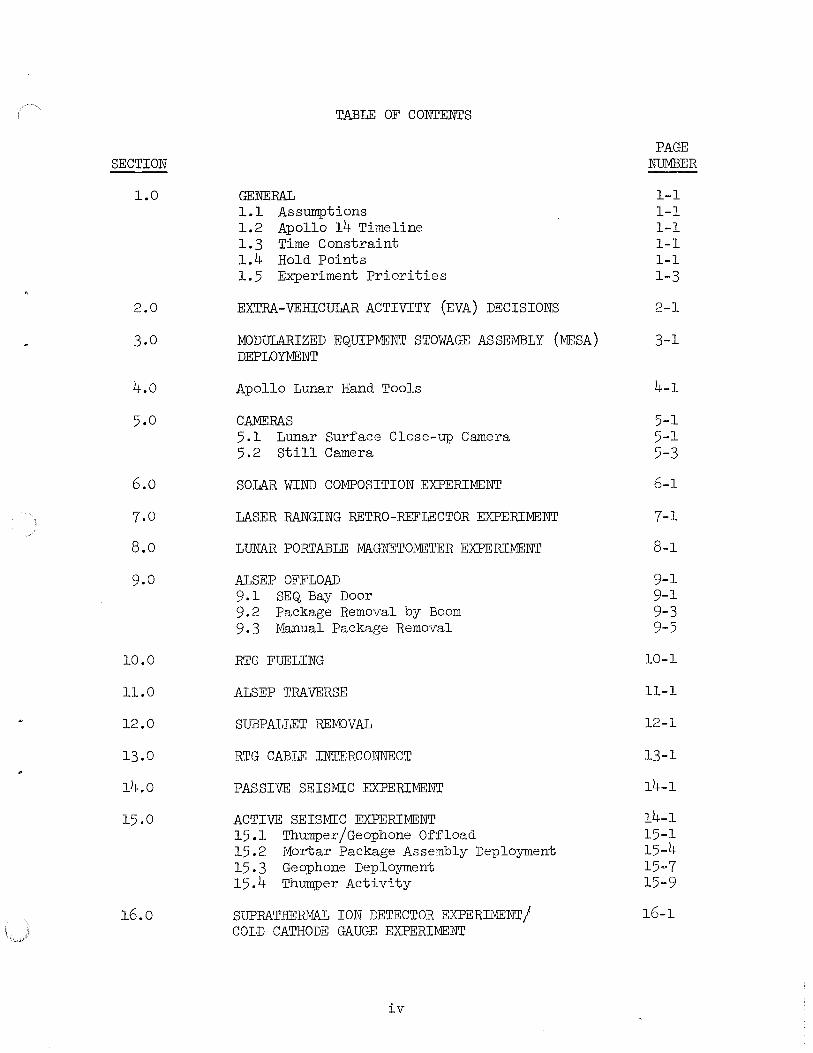
TABLE OF CONTENTS
GENERAL 1.1 Assumptions 1.2 Apollo 14 Timeline 1.3 Time Constraint 1.4 Hold Points 1.5 Experiment Priorities
EXTRA-VEHICULAR ACTIVITY (EVA) DECISIONS
MODULARIZED EQUIPMENT STOWAGE ASSE:MBLY (MESA) DEPLOYMENT
Apollo Lunar Hand Tools
CAMERAS 5.1 Lunar Sur~ace Close-up Camera 5.2 Still Camera
SOLAR WIND COMPOSITION EXPERIMENT
LASER RANGING RETRO-REFLECTOR EXPERIMENT
LUNAR PORTABLE MAGNETOMETER EXPERIMENT
ALSEP OFFLOAD 9.1 SEQ Bay Door 9.2 Package Removal by Boom 9.3 Manual Package Removal
RTG FUELING
ALSEP TRAVERSE
SUBPALLET REMOVAL
RTG CABLE INTERCONNECT
PASSIVE SEISMIC EXPERIMENT
ACTIVE SEISMIC EXPERIMENT 15.1 Thumper/Geophone O~~load 15.2 Mortar Package Assembly Deployment 15.3 Geophone Deployment 15.4 Thumper Activity
SUPRATHERMA.L ION DETECTOR EXPERIMENT/ COLD CATHODE GAUGE EXPERIMENT
iv
PAGE NUf'ilBER
1-1 1-1 1-1 1-1 1-1 1-3
2-1
3-1
4-1
5-l 5-l 5-3
6-1
7-1
8-1
9-1 9-1 9-3 9-5
10-1
11-1
12-1
13-1
14-1
14-1 15-1 15-4 15··7 15-9
16-1

SECTION PAGE
NUMBER
17.0 CHARGED PARTICLE LUNAR ENVIRONMENT EXPERIMENT 17-1
18.0 CENTRAL STATION 18-1
19.0 ALSEP ACTIVATION 19-l
20.0 CSM/LM S-BAND TRANSPONDER 20-1
21.0 DOWN-LINK BI-STATIC RADAR OBSERVATION OF THE MOON 21-1
22.0 GEGENSHEIN FROM LUNAR ORBIT 22-l
23.0 ABBREVIATIONS AND ACRONYMS 23-l
v

1.0 GENERAL
1.1 ASSUMPTIONS
a. Launch delays o~ more than a ~ew days may require replacement or adjustment o~ some experiment hardware.
b. For earth orbit mission case, the altitude and inclination will both be increased within operational limitations.
c. An experiment may be operated ~or engineering tests only, i~ orbit will not allow ~or science data collection.
d. I~ the mission is o~~-nominal so that it appears unlikely that there will be no more than one sur~ace EVA, in order to increase the possibility o~ collecting Fra Mauro material in the selected samples, the ALSEP should be deployed in a direction toward the nearest available and recognizable Fra Mauro material.
1. 2 APOLLO 14 TIME LINE
The Apollo 14 Lunar Sur~ace Timeline is used ~or planning lunar sur~ace EVA contingency procedures. The Lunar Sur~ace Timelines are essentially task ~low analyses along a time base, showing the points o~ interaction between the two crewmen.
For a more detailed timeline procedure re~er to the Mission H-3/ Apollo 14 Flight Plan.
1.3 TIME CONSTRAINT
For any mal~unction on a scienti~ic task; spend a maximum o~ 10 minutes on mal~unction procedures, then abandon. Additional time may be allocated on certain mal~unctions that would result in total experiment abandonment. This additional time will be a real-time decision based on consumables and timeline constraints.
1. 4 HOLD POINTS
The sequence o~ the experiment deployment or operation may be stopped a~er the completion o~ any one o~ the ~allowing hold points to be continued at some time later by going to the next series o~ tasks.
l-1

1.4 (Cont'd)
a. O~~load LRRR and emplace LRRR Array in and ~acing the sun.
b. Remove ALSEP Packages #l and #2; close SEQ bay door; emplace ALSEP packages with experiments in and ~acing the sun.
c. Tilt ~uel cask; dome not removed.
d. Tilt ~uel cask; remove dome, do not de~uel.
e. Fuel RTG; carry ALSEP to deployment site; remove subpallet ~rom Package #2; carry Package #1 to emplace site (do not deploy); interconnect RTG cable (do not actuate shorting switch).
~. Deploy ALSEP Package #1 as well as ALSEP Package #2; release and remove experiment~ raise sunshield; mount and aim antenna; deploy PSE.
g. Deploy ALSEP experiments and complete tasks. A hold point exists ~ter each experiment is deployed.
1-2
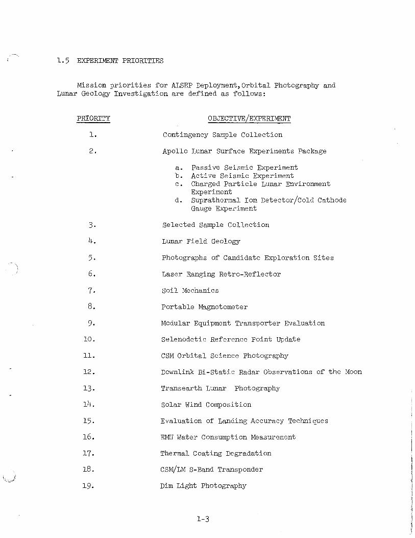
1. 5 EXPERIMENT PRIORITIES
Mission priorities for ALSEP Deployment,Orbital Photography and Lunar Geology Investigation are defined as follows:
PRIORITY
l.
2.
3.
4.
5.
6.
7.
8.
9.
10.
11.
12.
13.
14.
15.
16.
17.
18.
19.
OBJECTIVE/EXPERIMENT
Contingency Sample Collection
Apollo Lunar Surface Experiments Package
a. Passive Seismic Experiment b. Active Seismic Experiment c. Charged Particle Lunar Environment
Experiment d. Suprathermal Ion Detector/Cold Cathode
Gauge Experiment
Selected Sample Collection
Lunar Field Geology
Photographs of Candidate Exploration Sites
Laser Ranging Retro-Reflector
Soil Mechanics
Portable Magnetometer
Modular Equipment Transporter Evaluation
Selenodetic Reference Point update
CSM Orbital Science Photography
Downlink Bi-Static Radar Observations of the Moon
Transearth Lunar Photography
Solar Wind Composition
Evaluation of Landing Accuracy Techniques
EMU Water Consumption Measurement
Thermal Coa~ing Degradation
CSM/LM S-Band Transponder
Dim Light Photography
1-3
'0 I !--'
Event No.
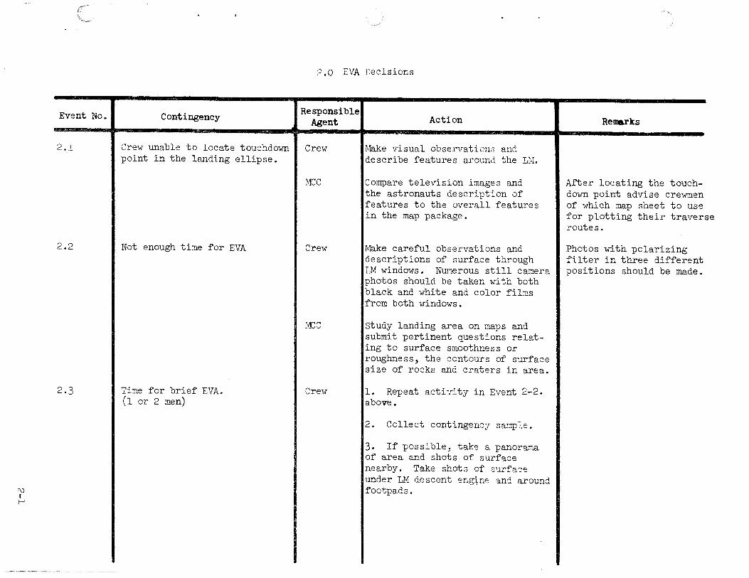
2.1
2.2
2.3
Contingency
Cre\v unable to locate touchdown point in the landing ellipse.
Not enough time for EVA
Ti~e for brief EVA. (l or 2 men)
2.0 EVA Decisions
Responsible Agent I Action I Renarks
Crei·l IMake visual observations and
MCC
Cre1v
:1CC
Crew
describe features around the Li·I.
Compare television images and the astronauts description of features to the overall features in the map package.
~~ke careful observations and descriptions of surface through LM windows. Numerous still camera photos should be taken with both black and white and color fil2s from both windows.
study landing area on maps and submit pertinent questions relating to surface smoothness or roughness, the contours of surface size of rocks and craters in area.
l. Repeat acti 7i ty in Event 2-2. above.
2. Collect contingency sa:;rple.
3. If possible, take a panorama of area and shots of surface nearby. Take shots of S'~rfa:::e under LM descent eng1nc and around footpads.
After locating the touchdown point advise cre•~en of which map sheet to use for plotting their traverse routes.
Photos with polarizing filter in three different positions should be made.

Event No.
2.4
1\)
1\)
Contingency
EVA l only. (2 men)
2.0 EVA Decisions
Responsible Agent
Crew
MCC
Action
l. Collect contingency sample.
2. Deploy ALSEP as normal but in direction toward the nearest available and recognizable Fra Mauro material.
3. Deploy LRRR.
4. Collect comprehensive sample during return traverse ~rom ALSEP site.
5. Collect documented samples during traverse to the ALSEP site and while returning.
6. Photograph and describe geological ~eatures as well as collect samples.
Study landing area on maps and make decision on ALSEP deployment site.
Remarks
Cut down the number o~ stations and distance attempted rather than reduce quality o~ sample collections and documentation.
During the EVA, should it become evident that there is not time to collect both the core and the selected sample, then the selected sample should be collected in liew o~ the core.

2.0 EVA Decisions
Event No. Contingency Responsible Action Agent Remarks
2.5 One Man EVA 1. (NO EVA 2) Crew 1. Collect contingency sample.
2. Deploy ALSEP as normal and according to priority listing in Mission Requirements Document, but in direction toward the near-est available and recognizable Fra Mauro material.
3. Deploy LRRR.
4. Collect documented samples Cut down the number of during return traverse from ALSEP stations and distance site. attempted rather than
reduce quality of sample collections and docu-mentation.
2.6 One man EVA 1 (EVA 2 planned). Crew 1. Collect contingency sample.
2. Deploy ALSEP as normal.
3. Deploy LRRR.
4. Collect documented samples during return traverse from ALSEP site.
£\) I
w .
---·- ··-~-·-·--·-·------
1\) I +
Event No.
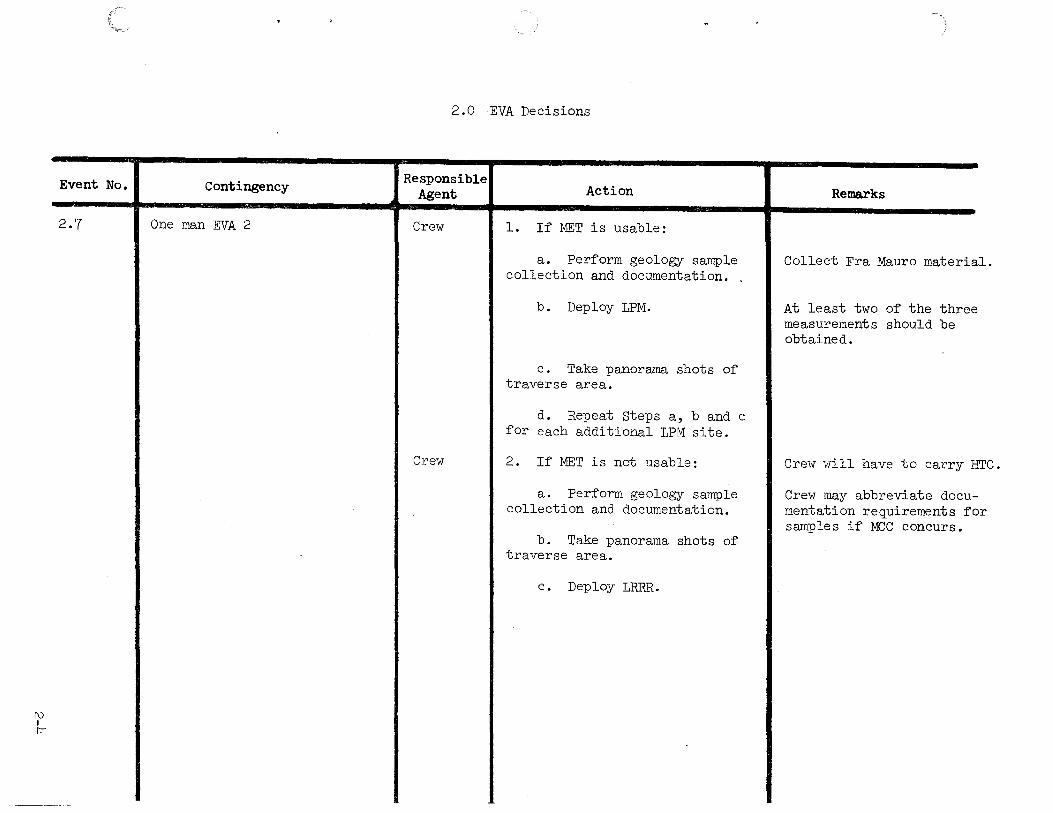
2.7
Contingency
One man EVA 2
2.0 EVA Decisions
Responsible Agent Action
Crew l. If MET is usable:
a. Perform geology sample collection and documentation.
b. Deploy LPM.
c. Take panorama shots of traverse area.
d. Repeat Steps a, b and c for each additional LPM site.
Crew 2. If MET is not usable:
a. Perform geology sample collection and documentation.
b. Take panorama shots of traverse area.
c. Deploy LRRR.
Remarks
Collect Fra Mauro materi l.
At least two of the thre measurements should be obtained.
Crew will have to carry HTC.
Crew may abbreviate docu mentation requirements f or samples if MCC concurs.

w I t-'
Event No.
3.1
3.2
3.3
Contingency
MESA release handle will not release
Release handle releases, MESA does not deploy.
MESA f'ails to stop and hits lunar surf'ace (lanyard breaks).
3.0 MESA Deployment
Responsible Agent
Crew
Crew
Crew
Action
l. Attempt to f'ree release handle by exerting side loads on pip pin.
2. Attempt to reach cable f'rom release handle to MESA. Pull on this cable or cable bell crank mechanism with hand to deploy MESA.
3. Attempt to reach cable beyond bell crank and pull to deploy MESA.
l. Try repeated pulls on release handle.
2. Manually deploy MESA f'rom surf'ace with lanyard.
3. One crewman pull on MESA lanyard while other crewman pulls release handle.
l. Attempt to block up MESA with LRRR pallet .
2. Attempt to tie up MESA if' lanyard available.
Remarks

3.0 MESA Deployment
Event No. Contingency Responsible Action Agent
3.4 Unable to open SRC. Crew l. Hit corners of SRC lid with hammer and attempt to pull lid free.
2. If forced to abandon SRC #l use MESA weigh bags for Selected Samples and transfer weigh bags to LM ascent stage in ETB and stow in the ISA.
3. If forced to abandon SRC #2, use MESA weigh bags for Docu-mented Samples and transfer weigh bags to LM ascent stage in the ETB and stow in the ISA. The SWC is to be transferred in the ETB and stowed in the ISA.
3.5 SRC Seal Area Dirty Crew Use hand brush to clean seal.
w ' f\)
Remarks
Loss of SRC #l will resul in the loss of 3 core tub and 2 SESC's.
Loss of SRC #2 will resul the loss of 3 core tubes, and the MSSC.
t es
t in l SESC,
_,.:: I .Al
Event No.
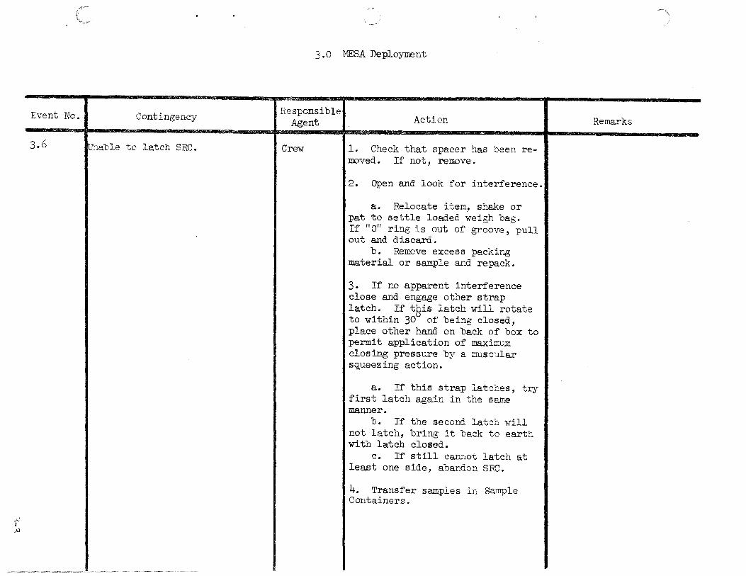
3.6
Contingency
1Jnable to latch SRC.
3 .0 "MESA Deployment
Responsible Agent
Crew
Action
l. Check that spacer has been removed. If not, remove.
2. Open and look for interference.
a. Relocate item, shake or pat to settle loaded i-Teigh bag. If "O" ring is out of groove, pull out and discard.
b. Remove excess packir~ material. or sample and repack.
3. If no apparent interference close and engage other strap latch. If this latch will rotate to within 30° of being closed, place other hand on back of box to permit application of maximuE closing pressure by a r:msc~.llar squeezing action.
a. If this strap latctes, try first latch again in the same manner.
b. If the second latch will not latch, bring it back to earth with latch closed.
c. If still canEot latch at least one side, abandon SRC.
4. Transfer samples i~ Sample Containers.
Remarks

3.0 MESA Deployment
Event No. Contingency Responsible
Action Remarks Agent
3.7 Unable to trru1sfer items via LEC. Crew l. Use LEC as a tether, attach and pull it up to hatch.
2. If possible climb ladder while holding SRC.
(__,._:, I .,_

..{::""" I I-'
Event No.
4.1
4.2
Contingency
Unable to attach extension handle.
Pull pin jams at ALSEP pallet/ HTC inter~ace.
4.0 Apollo Lunar Hand Tools
Responsible Agent Action Remarks
Crew l. Veri~y locking collar will not rotate.
2. Hit locking collar against.LM on MESA to attempt to ~ree Jockine mechanism.
Crew l. Apply additional ~orce while HTC - hand tool carrier. rotating pin with the aid o~ the second crewman.
2. Use MESA hammer to pry pin ~ree or break pin.
3. Attempt to pry HTC ~ree ~rom ALSEP pallet.
4. Remove all accessible tools, stow on MESA and deploy sub-package #2 with HTC attached .

Event No.
4.3
4.4
4.5
+ I
1\)
Contingency
HTC quarter turn fastener jams or will not release.
HTC legs on carrier will not extend and lock.
HTC will not open to deployed position.
4.0 Apollo Lunar Hand Tools
Responsible Agent
Crew
Crew
Crew
Action
l. Apply additional force while rotating t turn pins with the aid of second crewman.
2. Use MESA hammer to rotate or break fasteners.
3. Attempt to pry HTC free from ALSEP pallet.
4. Remove all accessible tools, stow on MESA and deploy Subpackage #2 with HTC attached.
Note: With HTC pull pins removed, the HTC can be partially removed at deployment site to provide better thermal view factor for RTG.
l. Apply additional force with the aid of second crewman.
2. Abandon task.
Remarks
If legs will not extend and lock there will be a reduced geology capability.
l. Request aid of second crewman. IThere will be a reduced geology capability if HTC will not open or lock.
2. Apply additional force with MESA hammer.
3. Abandon task.
+ I
\..A)
Event No.
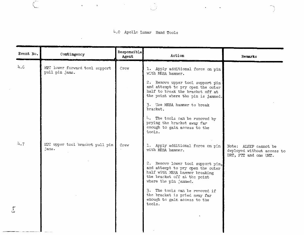
4.6
4.7
Contingency
HTC lower forward tool support pull pin jams.
HTC upper tool bracket pull pin jams.
4.0 Apollo Lunar Hand Tools
Responsible Agent
Crew
Crew
Action
l. Apply additional force on pin with MESA hammer.
2. Remove upper tool support pin and attempt to pry open the outer half to break the bracket off at the point where the pin is jammed.
3. Use MESA hammer to break bracket.
4. The tools can be removed by prying the bracket away far enough to gain access to the tools.
l. Apply additional force on pin with MESA hammer.
2. Remove lower tool support pin, and attempt to pry open the outer half with MESA hammer breaking the bracket off at the point where the pin jammed.
3. The tools can be removed if the bracket is pried away far enough to gain access to the tools.
Remarks
Note: ALSEP cannot be deployed without access to DRT, FTT and one UHT •
+ I +
Event No.
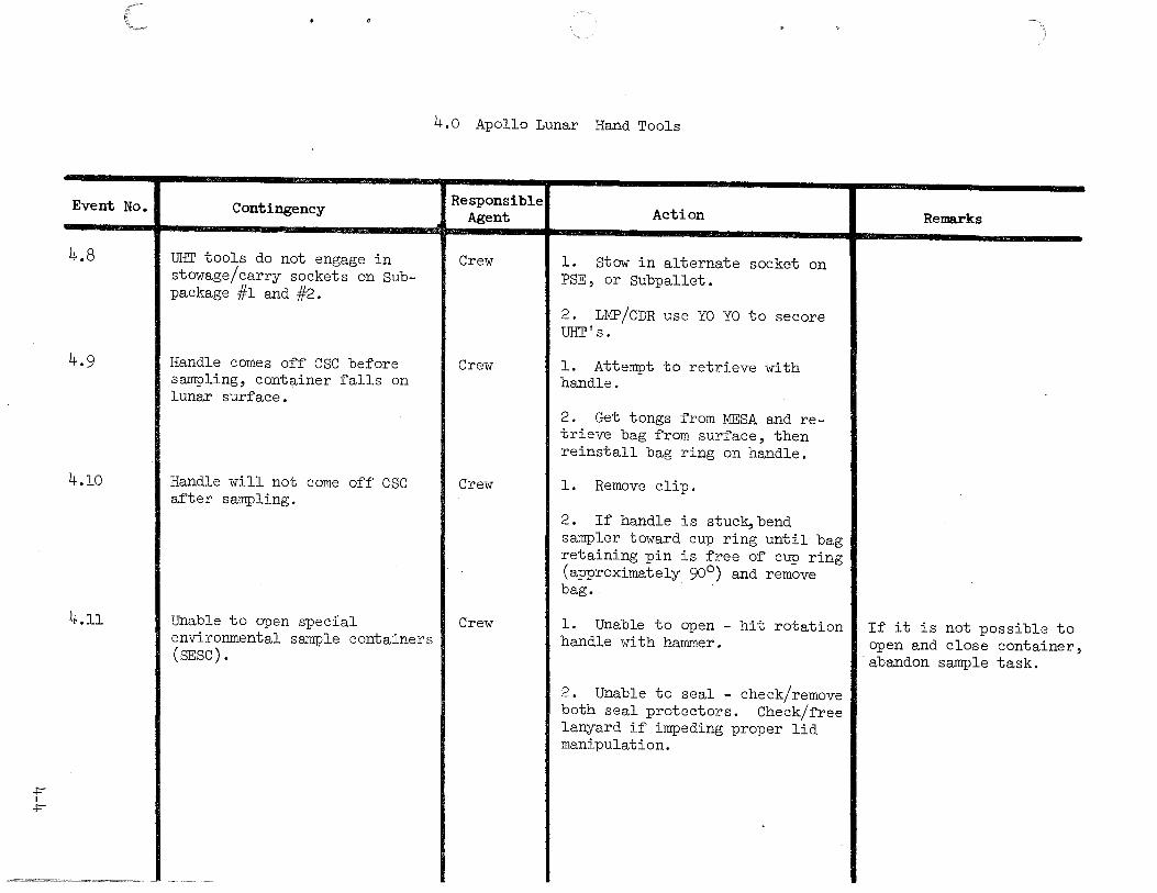
4.8
4.9
4.10
4.11
Contingency
UHT tools do not engage in stowage/carry sockets on Subpackage #l and #2.
Handle comes off CSC before sampling, container falls on lunar surface.
Handle will not come off esc after sampling.
Unable to open special environmental sample containers (SESC).
4.0 Apollo Lunar Hand Tools
Responsible Agent
Crew
Crew
Crew
Crew
Action
1. stow in alternate socket on PSE, or Subpallet.
2. LMP/CDR use YO YO to secore UHT's.
1. Attempt to retrieve with handle.
2. Get tongs from MESA and retrieve bag from surface, then reinstall bag ring on handle.
1. Remove clip.
2. If handle is stuck,bend sampler toward cup ring until bag retaining pin is free of cup ring (approximately 90°) and remove b~. .
l. Unable to open - hit rotation handle with hammer.
2. Unable to seal - check/remove both seal protectors. Check/free lanyard if impeding proper lid manipulation.
Remarks
If it is not possible to open and close container, abandon sample task.
+ I
\Jl
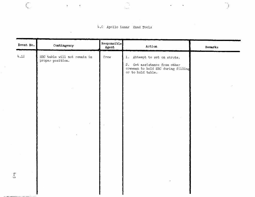
Event No.
4.12
Contingency
SRC table will not remain in proper position.
4.0 Apollo Lunar Hand Tools
Responsible Agent Action Remarks
Crew 1. Attempt to set on struts.
2. Get assistance ~rom other crewman to hold SRC during ~illin~ or to hold table.
.

\Jl I
t--'
Event No.
5.1.1
5.1.2
5.1.3
5.0 CAMERAS
5.1 Lunar Surface Close-Up Camera
Contingency
Cycle light does not come on after depressing trigger on first exposure.
Responsible Agent
Crew
Cycle light does not come on I Crew after depressing trigger first time and red scale marks on camera skirt are visible.
Cycle light remains on for more I Crew than 10 seconds.
Action
Determine if red scale marks on camera top skirt are visible, indicating skirt is fully deployed. If marks are not visible depress camera skirt and release, noting if both latches are released.
Depress the black safety switch located to the left of the handle extension pole base and push camera down until skirt is fully retracted and then release. Repeat two times. Repeat exposure noting if flash discharged and cycle light comes on. If flash discharges and cycle light does not come one, cycle light has failed, but camera is still operative. Continue photography allowing 15 seconds between exposures. If flash does not discharge discard camera.
If cycle light goes off within 25 seconds continue photography. If cycle light does not go off after 25 seconds, and pictures have been taken, remove cassette and discard camera.
Remarks
Note: Occasionally the last skirt retaining latch released will catch in a secondary mode and not permit the skirt to fully extend and enable the camera.
\Jl I f\)
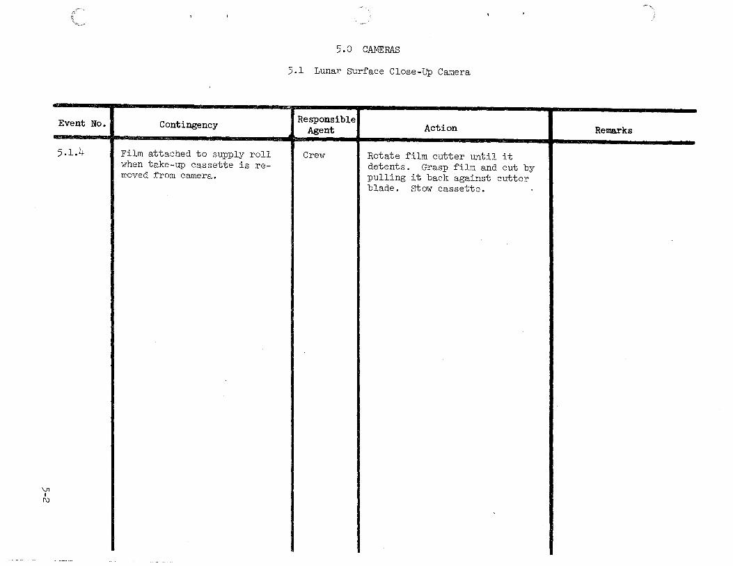
Event No.
5 .l.lJ.
Contingency
Film attached to supply roll when take-up cassette is re-moved ~rom camera.
5.0 CAMERAS
5.1 Lunar Sur~ace Close-up Camera
Responsible Agent Action Remarks
Crew Rotate ~ilm cutter until it detents. Grasp ~ilm and cut by pulling it back against cutter blade. stow cassette.

Vl I
w
Event No.
5.2.1
Contingency
Still camera not working.
5.0 CAMERAS
5.2 Still Camera
Responsible Agent Action Remarks
Crew l. Try new magazine and take tes photographs through window.
2. Keep in view of television and time sequence cameras so long as data return not compromised.
3. Use photomap if LM location is known,to locate sampling sites with reference to LM.
0\
I-'
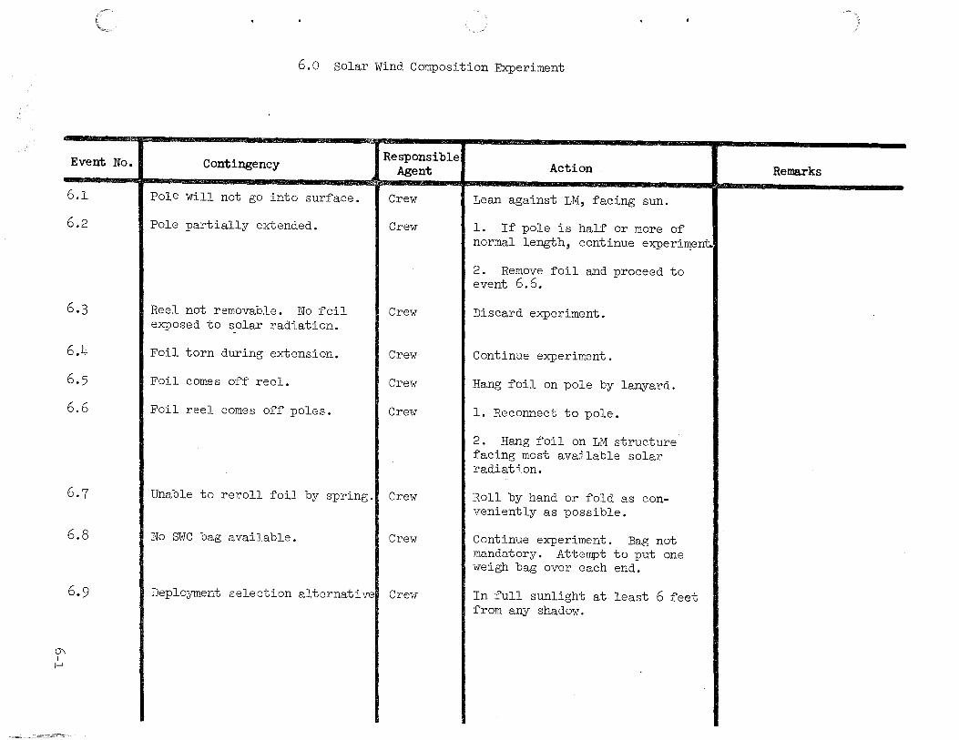
Event No.
6.1
6.2
6.3
6.4
6.5
6.6
6.7
6.8
6.9
6.0 Solar Wind Composition Experiment
Contingency
Pole will not go into surface.
Pole partially extended.
I Reel not removable. No foil exposed to ~olar radiation.
Foil torn during extension.
Foil comes off reel.
Foil reel comes off poles.
Responsible Agent
Crew
Crew
I Crew
I Crew
I Crew
Cre1v
Unable to reroll foil by spring.l Crew
No SWC bag available. I Crew
Deployment selection alternative& Crew
Action
Lean against LM, facing sun.
l. If pole is half or more of normal length, continue experi~ent.i
2. Remove foil and proceed to event 6. 6.
Discard experiment.
Continue experiment.
Hang foil on pole by lanyard.
l. Reconnect to pole.
2. Hang foil on LM structure facing most available solar radiation.
Roll by hand or fold as conveniently as possible.
Continue experiment. Bag not mandatory. Attempt to put one weigh bag over each end.
In full sunlight at least 6 feet from any shadow.
Remarks

--::J I 1-'
Event No.
7.1
-- ·-·~---' ---·---·----·------
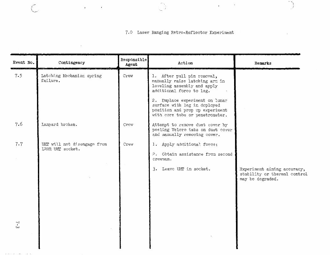
7.0 Laser Ranging Retro-Reflector Experiment
Contingency
Unable to deploy LRRR at least 100 feet west of Central Station
Responsible Agent
Crew
Action
1. Locate LRRR as far west of Central Station as possible.
2. Locate LRRR as far northwest or north of Central Station as possible, as far from mortar package flight path as possible and at least 300 feet from LM.
3. Locate LRRR as far southwest or south of Central station as possible, as far from mortar package and geophone line as possible and at least 300 feet from LM.
4. Locate LRRR east or northeast of Central Station at least 300 feet from LM, and at least 10 ft. from the RTG.
5. Locate LRRR southeast of Central Station, at least 300 feet from LM, at least 10 feet from RTG, and as far as possible from mortar package and geophone line.
Remarks
Note: Possible thermal degradation of LRRR due to deposition of lunar debris kicked up by grenade impact, mortar package blast, LM ascent stage blast, and RTG heating.

Event No.
7.2
7.3
7.4
-'1 I fl)
7.0 Laser Ranging Retro-Re~lector Experiment
Contingency
UHT will not engage in LRRR UHT socket.
Responsible Agent
Crew
LBRR tips over during deployment I Crew
Leveling leg pull pin jams or unable to deploy.
Crew
Action
1. Try to engage UHT in second UHT socket.
2. Try to engage second UHT in both UHT sockets.
3. IF UHT engagement ~ails, use UHT handle hooked into carry handle to rotate LRRR to lunar surface. Attempt to use UHT handle hooked into carry handle to level and align LRRR.
l. Pick up unit using UHT handle as a hook.
2. Brush off with EMU brush.
l. Attempt to pry pin out or jar leg free.
2. Attempt to level using core tube or penetrometer ~or props.
Remarks
LRRR aiming accuracy may be degraded.
Dust will degrade performance if the unit tips over on the array with the dust cover of~.
Leveling may be out of limits.
Experiment aiming accuracy stability on the thermal control may be degraded.
Event No.
7.5
7.6
7.7
---1 I
w
Contingency
Latching Mechanism spring ~ailure.
Lanyard broken.
UHT will not disengage from LRRR UHT socket.
7.0 Laser Ranging Retro-Re~lector Experiment
Responsible Agent
Crew
Crew
Crew
Action
1. A~ter pull pin removal, manually raise latching arm in leveling assembly and apply additional ~orce to leg.
2. Emplace experiment on lunar sur~ace with leg in deployed position and prop up experiment with core tube or penetrometer.
Attempt to remove dust cover by peeling Velcro tabs on dust cover and manually removing cover.
l. Apply additional ~orce:
2. Obtain assistance ~rom second crewman.
3. Leave UHT in socket.
Remarks
Experiment alming accuracy, stability or thermal control may be degraded.

Event No.
8.1
8.2
8.3
())
1-'
8.0 Lunar Portable Magnetometer Experiment
Contingency
Tripod leg does not lock in extended position
The ~lat cable will not deploy ~rom the cable reel because o~ binding within the reel.
The retaining clip in the tripod u channel does not engage.
Responsible Agent
Crew
Crew
Crew
Action
Deploy the de~ective leg ~irst, and drag it in the soil while positioning the other two legs.
l. Rotate the cable reel crank arm in the cable stowage direction until winding resistance is noted. Attempt to deploy cable again.
2. I~ the ~ull length o~ cable (35 ~eet) is not deployed, describe in detail to MCC, the sensor - METS-Astronaut co~iguration.
Maintain a grasp on the sensor head during tripod leveling and alignment.
Remarks
Dragging the legs will apply a bending torque to the leg and with the ~riction between the sliding sections the leg will re main deployed.
The cable may have vibrated during ~light to lunar sur~ace to an unusual state causing the cable to bind against the inside o~ the reel.
The ~ailure to engage the retaining clip will require additional operations by the crewman, but it will not a~~ect the equipment's operation.

():) I
f\)
Event No.
8.4
8.5
8.6
8.0 Lunar Portable Magnetometer Experiment
Contingency
The cable reeling task (stowage) not possible because:
a. Crank arm not operable.
b. Cable binds in reel.
c. Lack of EVA time.
The sensor head is dropped during setup, operation or transport.
Not enough time for all planned measurements.
Responsible Agent
Crew
Crew
Action
l. Pick up cable reel and handcarry it, dragging cable in soil.
2. Grasp cable and drag cable· and reel along lunar surface.
Retrieve sensor with scoop or by lifting cable and continue.
Priority of Measurements
a. Site Survey (all 3 positions)
b. Traverse measurement at maximum distance from LM during traverse (sensor head in position 3).
c. Normal second traverse measurement.
Remarks
Sensor head must be minl mum 250 feet from 1M and 35 feet from any other hardware.
Normally all 3 measurements required. More than 3 highly desirable.
Event No.
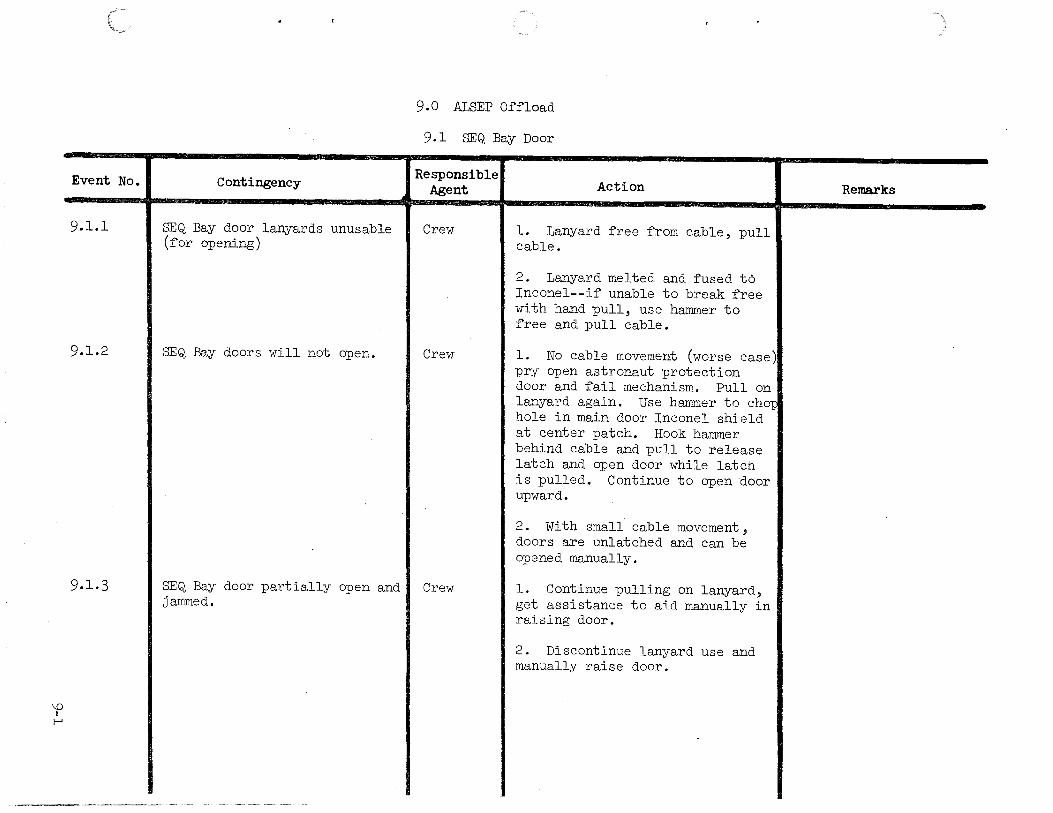
9.1.1
9.1.2
9.1.3
\0
1-'
Contingency
SEQ Bay door lanyards unusable (for opening)
SEQ Bay doors will not open.
SEQ Bay door partially open and jammed.
9.0 ALSEP Offload
9.1 SEQ Bay Door
Responsible Agent
Crew
Crew
Crew
Action
l. Lanyard free from cable, pull cable.
2. Lanyard melted and fused to Inconel--if unable to break free with hand pull, use hammer to free and pull cable.
l. No cable movement (worse case) pry open astronaut protection door and fail mechanism. Pull on lanyard again. Use hammer to chor hole in main door Inconel shield at center patch. Hook hammer behind cable and pull to release latch and open door while latch is pulled. Continue to open door upward.
2. With small cable movement, doors are unlatched and can be opened manually.
l. Continue pulling on lanyard, get assistance to aid manually in raising door.
2. Discontinue lanyard use and manually raise door.
Remarks

\0 I
1\)
Event No.
9.1.4
9.1.5
Contingency
SEQ Bay Door will not lower (for closing).
SEQ Bay door partially closed.
9.0 ALSEP Offload
9.1 SEQ Bay Door
Responsible Agent Action Remarks
Crew Attempt to close manually. Note: SEQ Bay door shoul d be closed to thermally insulate the LM.
Crew 1. Continue pulling on lanyard while second crewman manually assists in closing door.
2. Discontinue use of lanyard and manually close door or use hammer to fail mechanism in order to close door.
.
\0 I
w
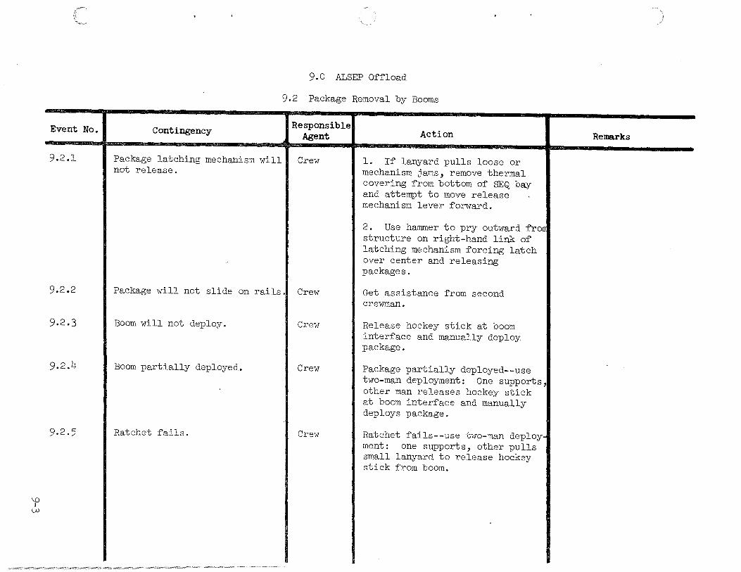
Event No.
9.2.1
9.2.2
9.2 .3
9.2.4
9.2.5
Contingency
Package latching mechanism will not release.
9.0 ALSEP Offload
9.2 Package Removal by Booms
Responsible Agent
Crew
Action
1. If lanyard pulls loose or mechanism jams, remove thermal covering from bottom of SEQ bay and attempt to move release mechanism lever forward.
2. Use hammer to pry outward frau structure on right-hand link of latching mechanism forcing latch over center and releasing packages.
Package will not slide on rails .1 Crew Get assistance from second crewman.
Boom will not deploy. Crew
Boom partially deployed. Crew
Ratchet fails. Crew
Release hockey stick at boom interface and manually deploy package.
Package partially deployed--use two-man deployment: One supports, other man releases hockey stick at boom interface and manually deploys package.
Ratchet fails--use two-man deployment: one supports, other pulls small lanyard to release hockey stick from boom.
Remarks
\D I
..t::""
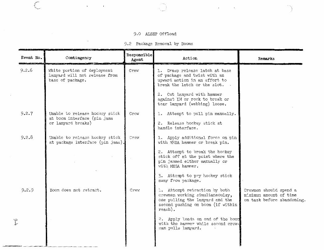
Event No.
9.2.6
9.2.7
9.2.8
9.2. 9
9.0 ALSEP Offload
9.2 Package Removal by Booms
Contingency
White portion of deployment lanyard will not release from base of package.
Responsible Agent
Crew
Unable to release hockey stick I Crew at boom interface (pin jams or lanyard breaks)
Unable to release hockey stick I Crew at package interface (pin jams).
Boom does not retract. Crew
Action
l. Grasp release latch at base of package and twist with an upward motion in an effort to break the latch or the slot.
2. Cut lanyard with hammer against LM or rock to break or tear lanyard (webbing) loose.
l. Attempt to pull pin manually.
2. Release hockey stick at handle interface.
l. Apply additional force on pin with MESA hammer or break pin.
2. Attempt to break the hockey stick off at the point where the pin jammed either manually or with MESA hammer.
3. Attempt to pry hockey stick away from package.
l. Attempt retraction by both crewmen working simultaneoulsy, one pulling the lanyard and the second pushing on boom (if within reach).
2. Apply loads on end of the boorr with the hammer while second crewman pulls lanyard.
Remarks
Crewmen should spend a minimum amount of time on task before abandoning.

Event No.
9.3.1
9.3.2
9.3.3
'0 I
\Jl
Contingency
Unable to release hockey stick at boom interface (Pin jammed or lanyard breaks)
Package latching mechanism will not release.
White portion of deployment lanyard will not release from base of package.
9.0 ALSEP Offload
9.3 Manual Package Removal
Responsible Agent
Crew
Crew
Crew
Action
l. Attempt to pull pin at pin interface.
2. Remove package on boom.
3. Remove entire hockey stick by removing pull pin at carry handle interface after boom removal.
l. If lanyard pulls loose or mechanism jams, remove thermal covering from bottom of SEQ bay and attempt to move release mechanism lever forward.
2. Use hammer claw to pry outward from structure on righ-hand link of latching mechanism forcing latch over center and releasing packages.
l. Grasp release latch at base of package and twist with an upward motion in an effort to break the latch or the slot.
2. Cut lanyard with hammer against LM or rock.
Remarks

\0 I 0'\
Event No.
9.3.4
9-3-5
Contingency
Package will not slide on rails
Unable to release hockey stick at package interface (pin jams)
9.0 ALSEP Offload
9.3 Manual Package Removal
Responsible Agent Action Remarks
Crew Using MESA tools with assistance of second crewman, attempt to clear package.
Crew 1. Apply additional force on pin with MESA hammer or break pin.
2. Attempt to break the hockey stick off at the point where the pin jammed, either manually or with MESA hammer.
3. Attempt to pry hockey stick away from package.
.

Event No.
10.1
10.2
10.3
t--' 0 I t--'
Contingency
Lanyard breaks or pulls away from cam lever.
Cam lever fails to release the upper trunnion after lever is fully deployed.
Lanyard fails to remove spline lock from cask/dome or breaks.
10.0 RTG Fueling
Responsible Agent
Crew
Crew
Crew
Action
Use MESA tools hammer/extension as hook and pull forward on cam lever to release.
Use hammer/extension as hook on astronaut guard to break cask free at trunnions while second crewman pulls lanyard to tilt.
l. Continue to release trunnion lock.
2. Rotate cask, attempt to gain access to fuel capsule by using hammer to destroy cask dome and pry away bands .
Remarks
Caution: Direct exposure to hot fuel cask could damage or fail the space suit.
If cam lever cannot be released, abandon ALSEP.
If upper trunnion cannot be released, abandon ALSEP.
If spline lock cannot be removed from dome, abandon ALSEP.

Event No.
10.4
10.5
t-' 0 I
[\)
Contingency
Cask will not rotate with lanyard.
Engaging mechanism on DRT does not lock due to mechanical failure.
10.0 RTG Fueling
Responsible Agent
Crew
Crew
Action
l. Verify upper trunnion release by attaching extension to MESA hammer, hook hammer on astronaut guard and ensure that the cask ls free of the upper trunnion.
2. Request aid of the second crewman to apply forward and downward force with hammer and extension on the guard while the first crewman attempts to rotate with the lanyard.
3. Continue to apply force to fail gear box if required.
4. If gear box fails, second crewman must support cask with the hammer/extension handle to the proper angle for fuel capsule removal.
1. Apply forward pressure and rotate. Attempt to remove dome with side loading on the DRT so it will be removed with some assistance from the· tool. (CAUTION: stand clear of dome when finally released and removed.)
2. Attempt to gain access to fuel capsule by using hammer to destroy cask dome and pry away b~nds.
Remarks
If cask cannot be rotated abandon ALSEP.
If dome cannot be removed, abandon ALSEP.

Event No.
I-' 0 I
w
10.6
10.7
10.8
Contingency
Lock nut assembly will not rotate.
•
Pretension bands do not release causing excessive loading on dome locking lugs.
FTT engagement fingers do not expand (inoperative)
10.0 RTG Fueling
Responsible Agent
Crew
Crew
Crew
Action
l. Apply additional force with hammer on the end of the DRT, side of cask and dome to "jar loose" the binding while contin-uing to rotate DRT. ·
2. Attempt to gain access to fuel capsule by using hammer to destroy cask dome and pry away bands •
l. Use MESA hammer to free lugs at the lock nut assembly on the dome.
2. Attempt to gain access to fuel capsule by using hammer to destroy cask dome and pry away bands.
1. Visually inspect fingers for debris.
2. Request aid of second crewman to apply additional force to FTT knob.
3. Apply impact pressure on knob by knocking on the LM landing gear.
Remarks
If assembly cannot be rotated, abandon ALSEP.
If lugs cannot be freed, abandon ALSEP.
If FTT will not function, the RTG cannot be fueled and ALSEP will be abandoned.
1-' 0 I +
Event No.
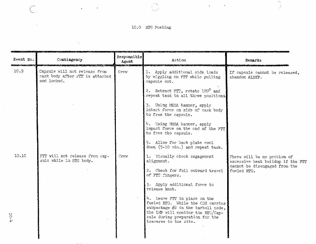
10.9
10.10
Contingency
Capsule will not release from cask body after FTT is attached and locked.
FTT will not release from capsule while in RTG body.
- ,-,;\;\l(\\).\!.\\l\\iW\\o\,;<1>-..,.1<\\\""'\WI'"'~'-,•b\\•Mi' l>•""'""'u,;C.U""-"""·'"";;-~,="";:~~·~~=-;r-..::C"=-~~~~- -- -
10.0 RTG Fueling
Responsible Agent
Crew
Crew
Action
l. Apply additional side loads by wiggling on FTT while pulling capsule out.
2. Retract FTT, rotate 120° and repeat task in all three position&
3. Using MESA hammer, apply intact force on side of cask body to free the capsule.
4. Using MESA hammer, apply impact force on the end of the FTT to free the capsule.
5. Allow for back plate cool down (5-10 min.) and repeat task.
1. Visually check engagement alignment.
2. Check for full outward travel of FTT fingers •
3. Apply additional force to release knob.
4. Leave FTT in place on the fueled RTG. While the CDR carries subpackage #2 in the barbell mode, the LMP will monitor the RTG/Capsule during preparation for the traverse to the site.
Remarks
If capsule cannot be released, abandon ALSEP.
There will be no problem of excessive heat buildup if the FTT cannot be disengaged from the fueled RTG.

Event No. Contingency
10.11 Tempilabel indicates tempera-ture of component is in excess of 250~.
f-' 0 I
\Jl
10.0 RTG Fueling
Responsible Agent Action
Crew Do not handle component manually. Use UHT or MESA tool to avoid direct contact with hot component.
Remarks
Direct exposure to temper tures in excess of 250~ damage or fail the space
acould suit.

1-' 1-' I
1-'
Event No.
11.1
11.2
Contingency
Carry bar will not engage in subpackage keyhole socket.
Carry bar sections become disengaged and rotate.
ll.O ALSEP Traverse
Responsible Agent
Crew
Crew
Action
l. Check mating bar to see i~ properly mated. Mating bar could be mated 180° out o~ phase.
2. Ensure ~lange on carry bar is ~ree o~ debris; i~ not, clean by impact or with gloved hand.
3. Ensure keyhole socket is clean; i~ not, clean with available MESA tools on UHT.
4. I~ one or both sockets are unuseable, the LMP must carry subpackage #l and subpackage #2 in suitcase modej CDR will pull MET and carry LR •
l. Attempt to relock carry bar' sections.
2. I~ carry bar sections do not lock, disengage carry bar ~rom subpackages. Use suitcase carry mode and transport carry bar on MET.
Remarks
The carry bar is required ~or use as an antenna mast and must be transported to the ALSEP deployment site.
I~ carry bar sections do not lock, ensure that sections are properly aligned when they are used as an antenna mast in order to permit proper alignment o~ ALSEP antenna.
t-' t-' I
1\)
Event No.
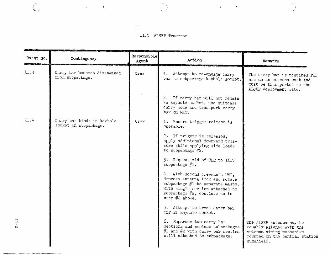
11.3
11.4
Contingency
Carry bar becomes disengaged from subpackage.
Carry bar binds in keyhole socket on subpackage.
11.0 ALSEP Traverse
Responsible Agent
Crew
Crew
Action
l. Attempt to re-engage carry bar in subpackage keyhole socket.
2. If carry bar will not remain in keyhole socket, use suitcase carry mode and transport carry bar on MET.
l. Ensure trigger release is operable.
2. If trigger is released, apply additional downward pressure while applying side loads to subpackage #2.
3. Request aid of CDR to lift subpackage #1.
4. With second crewman's UHT, depress antenna lock and rotate subpackage #l to separate masts. With single section attached to subpackage #2, continue as in step #2 above.
5. Attempt to break carry bar off at keyhole socket.
6. Separate two carry bar sections and emplace subpackages #l and #2 with carry bar section still attached to subpackage.
Remarks
The carry bar is required for use as an antenna mast and must be transported to the ALSEP deployment site.
The ALSEP antenna may be roughly aligned with the antenna aiming mechanism mounted on the central station sunshield.

Event No.
11.5
11.6
11.7
11.8
11.9
1-' 1-' I
w
ll.O ALSEP Traverse
Contingency
Planned deployment site)>300 feet west of LM (12 o'clock) unsuitable for ALSEP deployment.
Planned deployment site includes a crater with walls that slope more than 5°.
Responsible Agent
Crew
Crew
Planned deployment site includesl Crew an outcropping whose height is greater than l foot.
Planned deployment site is in LM shadow.
Planned deployment site is comprised of loose, granular soil or small rocks.
Crew
Crew
Action
Select alternate site;>300 feet Northwest to West or Southwest to West of LM.
Locate ALSEP components on rim of crater, on elevated local terrain or select another deployment site.
l. Locate ALSEP components at least 12 feet from a 1-foot outcropping, 24 feet from a two-foot outcropping, etc.
2. If coutcropping cannot be avoided, orient ALSEP components thermal radiators away from outcropping (so as to achieve a clear view of space).
Locate ALSEP components outside LM shadow, but within + 15° of E-W axis drawn through LM.
l. Compact individual aTeas prior to final emplacement of each ALSEP component.
2. Attempt to avoid emplacing ALSEP components on small rocks.
Remarks
Landing site analysis may provide additional inputs
If the craters south wall slopes more than 5°, select another deployment site.
Separation distance from LM is more critical than angular relationship with respect to LM E-W axis.
1-' fl) I
1-'
Event No.
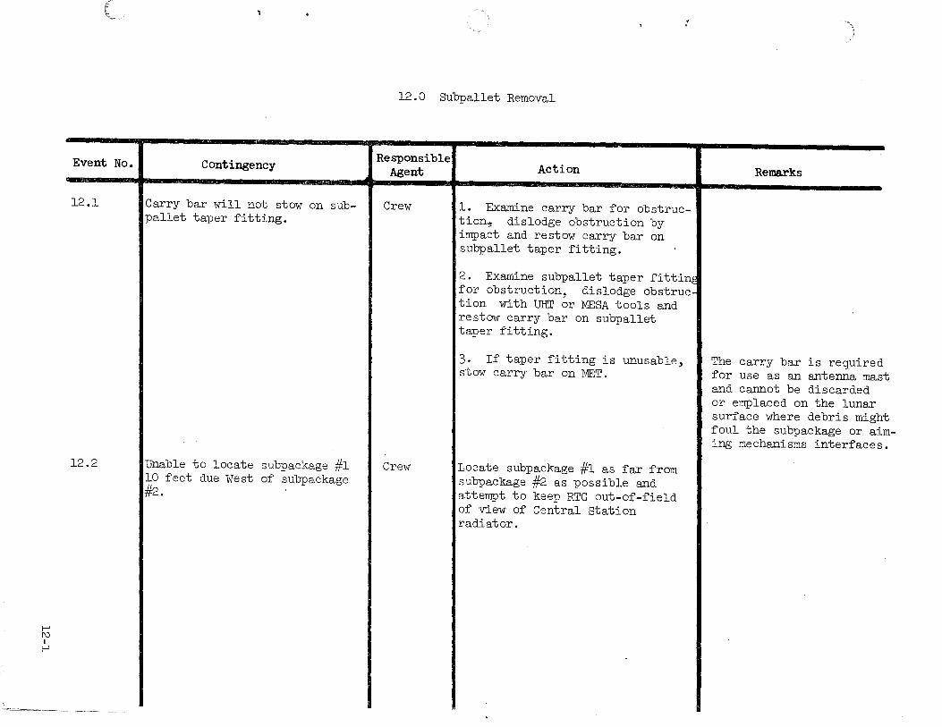
12.1
12.2
Contingency
Carry bar will not stow on subpallet taper fitting.
Unable to locate subpackage #l 10 feet due West of subpackage ~-
1'
12.0 Subpallet Removal
Responsible Agent
Crew
Crew
Action
l. Examine carry bar for obstruction~ dislodge obstruction by impact and restow carry bar on subpallet taper fitting.
2. Examine subpallet taper fittine for obstruction, dislodge obstruction with UHT or MESA tools and restow carry bar on subpallet taper fitting.
3. If taper fitting is unusable, stow carry bar on MET.
Locate subpackage #l as far from subpackage #2 as possible and attempt to keep RTG out-of-field of view of Central Station radiator.
Remarks
The carry bar is required for use as an antenna mast and cannot be discarded or emplaced on the lunar surface where debris might foul the subpackage or aiming mechanisms interfaces

Event No.
12.3
12.4
1-' f\) I f\)
Contingency
Subpallet boydbolt spline will not depress.
Subpallet boydbolt will not rotate.
12.0 Subpallet Removal
Responsible Agent
Crew
Crew
Action
l. Check hex head of UHT and, if damaged, use second UHT.
2. Use hammer on top of UHT to force depression of boydbolt spline.
3. Attempt to overcome spline lock by forcefully rotating UHT.
4. Leave subpallet on subpackage #2.
l. Check hex head of UHT and, if damaged, use second UHT.
2. Remove SIDE/CCGE, PSE Stool and antenna aiming mechanism and then use MESA hammer to attempt to break fastener.
3. Leave subpallet on subpackage ~.
Remarks
If subpallet cannot be removed, RTG will not radiate heat evenly causing excessive heat buildup.
If subpallet cannot be removed, RTG will not radiate heat evenly, causing excessive heat buildup.
Event No.
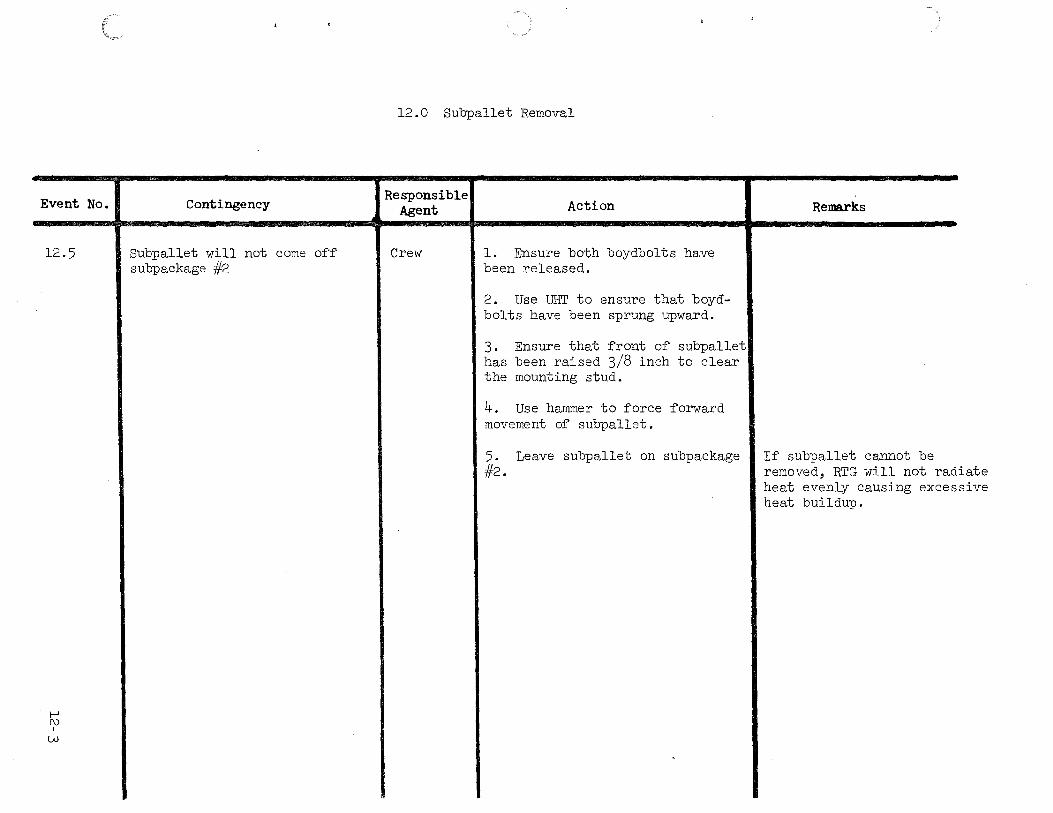
12.5
I-' f\) I
w
Contingency
Subpallet will not come off subpackage #2
12.0 Subpallet Removal
Responsible Agent
Crew
Action
1. Ensure both boydbolts have been released.
2. Use UHT to ensure that boydbolts have been sprung upward.
3. Ensure that front of subpallet has been raised 3/8 inch to clear the mounting stud.
4. Use hammer to force forward movement of subpallet.
5. Leave subpallet on subpackage #2.
Remarks
If subpallet cannot be removed, RTG will not radiate heat evenly causing excessive heat buildup.

1-' w
I 1-'
Event No.
13.1
Contingency
RTG cable reel boydbolts cannot be released.
13.0 RTG Cable Interconnect
Responsible Agent
Crew
Action
1. Visually check (if possible) to see if bolt is released and not loose/raised due to side loading.
2. Check for spring loading on bolt.
3. Repeat release procedure, i.e. engage depress, rotate ccw 75°.
4. Insert UHT and apply downward pressure on center spline. Use hammer if necessary, turn ccw to release.
5. If spline is depressed and bolt will not rotate, back off slightly cw then turn back ccw~ and wiggle.
6. Visually check hex head on UHT and if broken, use second tool.
7. If procedure fails to release bolts, tilt package on carry handle side, and utilize UHT to unwind cable manually to expose shorting plug.
8. With the aid of the second crewman, release pull pin and retainers.
9. Lower package to lunar surface,
Remarks
Exercise caution when working in close proximity to hot RTG.
If RTG cable reel cannot be removed, RTG will not radiate heat evenly, causing excessive heat buildup.

Event No.
13.2
1-' w
I 1\J
Contingency
Cable reel falls to the lunar surface when final boydbolt is removed.
13.0 RTG Cable Interconnect
Responsible Agent
Crew
Action
1. Retrieve cable reel with UHT handle. Determine tempilabel temperature. If under 250°F, grasp reel assembly, connect ~' and continue deployment.
2. If tempilabel indicates a temperature over 250°F, request the aid of the second crewman. The CDR will retrieve reel with UHT, deploy the cable, lay the reel assembly on subpackage #1, secure with UHT and continue deployment.
Remarks
1-' w I
w
Event No.
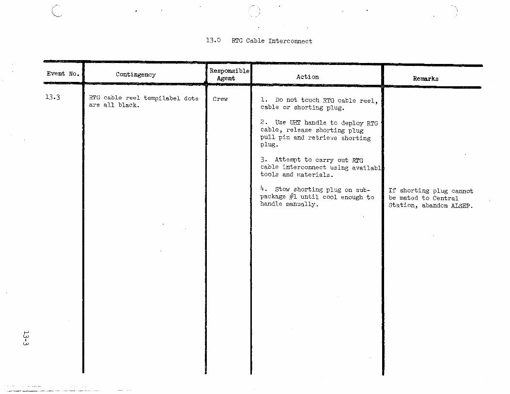
13.3
Contingency
RTG cable reel tempilabel dots are all black.
13.0 RTG Cable Interconnect
Responsible Agent Action Remarks
Crew l. Do not touch RTG cable reel, cable or shorting plug.
2. Use UHT handle to deploy RTG cable, release shorting plug pull pin and retrieve shorting plug.
3. Attempt to carry out RTG cable interconnect using availabl tools and materials.
4. Stow shorting plug on sub- If shorting plug cannot package #1 until cool enough to be mated to Central handle manually. Station, abandon ALSEP.

13.0 RTG Cable Interconnect
Event No. Contingency Responsible Action Agent Remarks
13.4 Shorting plug pull pin does not Crew 1. Apply additional force while release. rotating pin.
2. Apply additional force on pin with MESA hammer or break pin.
3. Use MESA hammer to break bracket.
4. Attempt to separate cable fran shorting switch.
5. If shorting plug cannot be If ALSEP deployment is mated to Central Station, abandon terminated anytime prior ALSEP. to Central Station acti-
vation, the RTG shorting plug reset lanyard will be pulled to assure the R .TG is shorted.
_. A)
I f:""
.

1-' w I
\Jl
Event No.
13.5
Contingency
~horting plug connector fails to engage and lock to Central station (c/s).
13.0 RTG Cable Interconnect
Responsible Agent Action Remarks
Crew l. Check shorting plug connector for proper orientation.
2. Check both connectors for debris on pins or C/S receptacle.
3. Depress outer flange of shorting plug connector to ensure proper function (t-" sliding action).
4. Reconnect applying additional downward pressure on the flange assembly with the LMP helping to provide additional stability (LMP can aid by holding PLSS).
5. Manually separate the shorting plug from the RTG cable, discard and connect RTG cable directly to cjs.
6. Abandon ALSEP.

Event No.
t-' w I 0\
13.6
13.7
13.8
Contingency
Ampere gauge unreadable due to debris or arrow in ampere gauge_ is at zero (no movement).
Shorting plug depressed but ammeter shows no drop in amperage.
Shorting plug engages, but fails off when subpackage is rotated.
13.0 RTG Cable Interconnect
Responsible Agent
Crew
Crew
Crew
Action
l. Report condition and continue ALSEP deployment.
2. Reset the shorting switch if reading is zero.
l. Reset the switch, and redepress.
2. Apply additional force to shorting plug and note if amperag drops.
3. Disconnect shorting plug from Central station, separate shortin1 plug from the RTG cable and connect RTG cable connector to Central Station.
l. Return subpackage to vertical position, retrieve cable, remove any debris and remate connectors.
2. Ensure locking mechanism is fully forward.
Remarks
Absence of amperage drop is not justification for abandoning ALSEP deployment.

1--' -(::"" I
1--'
Event No.
14.1
14.2
14-3
14.0 Passive Seismic Experiment
Contingency Responsible Agent
Deploy PSE Stool (Boyd bolt fails] Crew to release)
Unable to deploy PSE stool 10 feet northwest of Central Station.
Unable to pack lunar surface.
Crew
Crew
Action
1. Insert UHT and apply downward pressure on center spline. Use hammer if necessary; turn ccw to release.
2. If spline is depressed and bolt will not rotate, back off slightly cw then turn back ccw and wiggle.
3. Visually check hex head on UHT if broken, use second tool.
4. Attempt to pry the retainer bracket assembly loose with MESA hammer.
Locate PSE stool as far from Central Station and ASE mortar package as possible.
Provide best PSE stool to lunar surface coupling that site will permit.
Remarks
The PSE sensor could be placed directly on the lunar surface, if the PSE stool cannot be released. Experiment thermal control and science may be degraded.
t-' .pI
[\)
Event No.
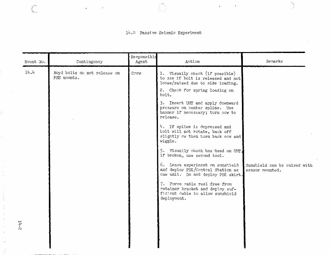
14.4
-,~,«==~-< ~-~ , '"" '"-""umc.>~>n~.----·~~-"~
Contingency
Boyd bolts do not release on PSE mounts.
14.0 Passive Seismic Experiment
ResponsiblE Agent Action Remarks
Crew l. Visually check (if possible) to see if bolt is released and not loose/raised due to side loading.
2. Check for spring loading on bolt.
3. Insert UHT and apply downward pressure on center spline. Use hammer if necessary; turn ccw to release.
4. If spline is depressed and bolt will not rotate, back off slightly cw then turn back ccw and wiggle.
5. Visually check hex head on UHT if broken, use second tool.
6. Leave experiment on sunshield Sunshield can be raised and deploy PSE/Central Station as sensor mounted.
with
one unit. Do not deploy PSE skirt.
7. Force cable reel free from retainer bracket and deploy suf-ficient cable to allow sunshield deployment.
~ I
w
Event No.
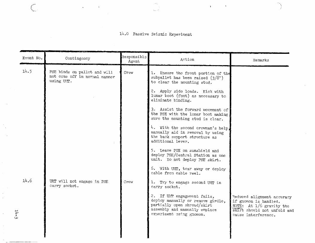
14.5
14.6
Contingency
PSE binds on pallet and will not come off in normal manner using UHT.
UHT will not engage in PSE carry socket.
14.0 Passive Seismic Experiment
~Responsible Agent
Crew
Crew
Action
l. Ensure the front portion of thE subpallet has been raised (3/8") to clear the mounting stud.
2. Apply side loads. Kick with lunar boot (foot) as necessary to eliminate binding.
3. Assist the forward movement of the PSE with the lunar boot making sure the mounting stud is clear.
4. With the second crewman's help manually aid in removal by using the back support structure as additional lever.
5. Leave PSE on sunshield and deploy PSE/Central Station as one unit. Do not deploy PSE skirt.
6. With UHT, tear away or deploy cable from cable reel.
l. Try to engage second UHT in carry socket.
2. If UHT engagement fails, deploy manually or remove girdle, partially open shroud/skirt assembly and manually emplace experiment using gnomon.
Remarks
Reduced alignment accuracy if gnomon is handled. NOTE: At l/6 gravity the skirt should not unfold and cause interference.

t-' +:-1 +:-
Event No.
14.7
14.8
14.9
14.10
Contingency
Experiment falls off UHT due to accidental triggering of UHT.
Experiment falls off PSE stool while leveling after skirt fully deployed.
Thermal shroud will not lay ~lat at outer edge.
UHT punctures thermal shroud during leveling sequence.
14.0 Passive Seismic Experiment
Responsible Agent
Crew
Crew
Crew
Crew
Action
l. Using UHT, retrieve cable and gently lift experiment with cable. Secure mounting lug (tab) with hand and attempt to re-engage UHT in socket.
2. If UHT engagement fails pull shroud pin, discard shroud/skirt assembly and emplace experiment manually using PSE gnomon as a handle.
l. Retrieve experiment with UHT handle hooked into gnomon opening and lift experiment.
2. Grasp thermal skirt and raise to a position to observe stool.
3. Lower experiment on stool.
Place discarded ALSEP parts and/or lunar rocks on shroud edge.
Remove UHT from puncture and attempt to cover the opening, if the hole remains.
Remarks
Reduced thermal control due to degradation of skirt and shroud assembly with lunar debris.
Reduced alignment accuracy due if gnomon is handled. NOTE: At l/6 gravity, skirt should not unfold and cause interference.
Reduced thermal control due to degradation of skirt and shroud assembly with lunar debris and reduced alignment accuracy due to handling of gnomon.
Experiment thermal control may be degraded.

1-' +=I
\Jl
Event No.
14.11
Contingency
Lunar debris degrades reada-bility o~ bubble leveling indicator and alignment index on shroud.
14.0 Passive Seismic Experiment
Responsible Action Remarks Agent
Crew l. Level by using the local sur- Improper alignment will ~ace area as a re~erence (PSE result in di~~iculty shadow). correlating PSE data to
a position on the lunar sur~ace.
2. Ensure ample picture coverage Without + 5° leveling o~ is obtained to veri~y experiment LP XYZ and tidal sensors, orientation. sensors will not operate.
1-' \.Jl I
1-'
Event No.
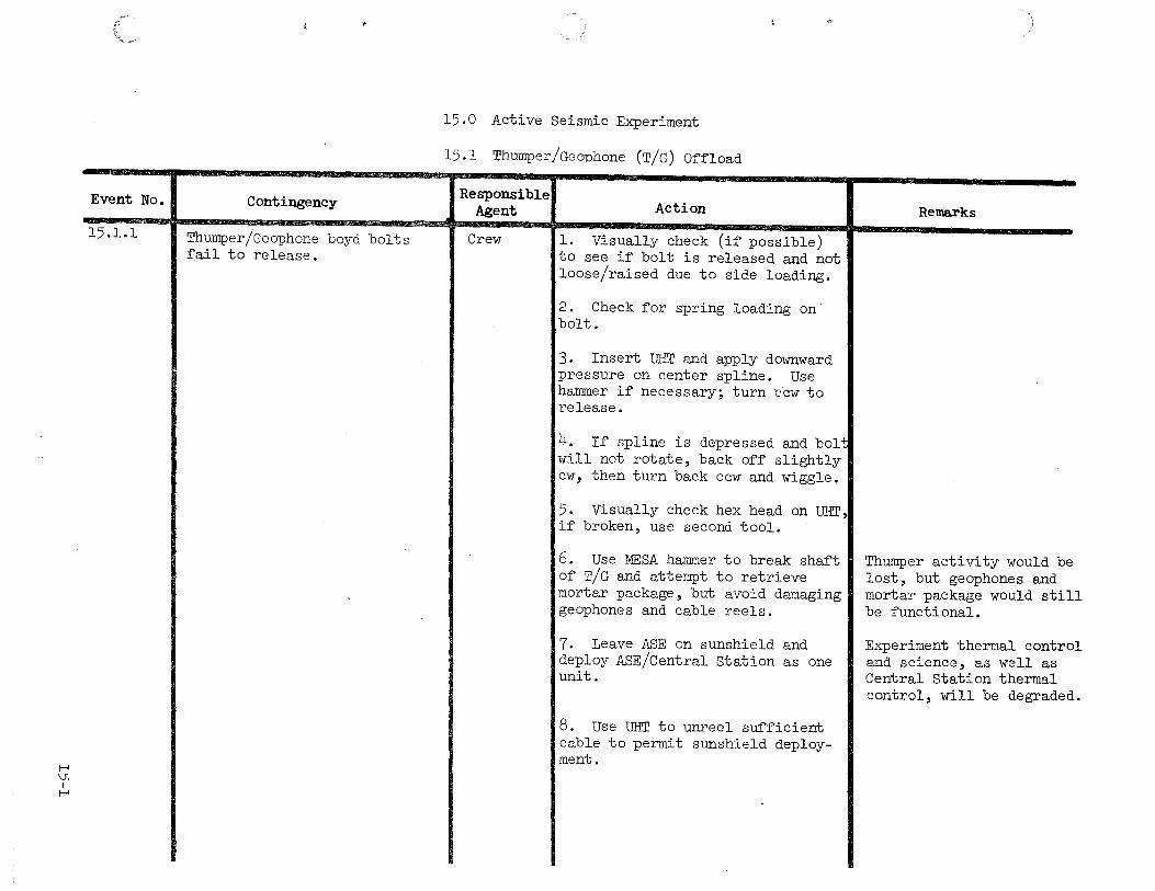
15.1.1
Contingency
Thumper/Geophone boyd bolts fail to release.
15.0 Active Seismic Experiment
15.1 Thumper/Geophone (T/G) Offload
Responsible Agent
Crew
Action
1. Visually check (if possible) to see if bolt is released and not loose/raised due to side loading.
2. Check for spring loading on bolt.
3. Insert UHT and apply downward pressure on center spline. Use hammer if necessary; turn ccw to release.
4. If spline is depressed and bolt will not rotate, back off slightly cw, then turn back ccw and wiggle.
5. Visually check hex head on UHT, if broken, use second tool.
6. Use :MESA hammer to break shaft of T/G and attempt to retrieve mortar package, but avoid damaging geophones and cable reels.
7. Leave ASE on sunshield and deploy ASE/Central Station as one unit.
8. Use UHT to unreel sufficient cable to permit sunshield deployment.
Remarks
Thumper activity would be lost, but geophones and mortar package would still be functional.
Experiment thermal control and science, as well as Central Station thermal control, will be degraded
I-' V1 I
1\)
Event No.
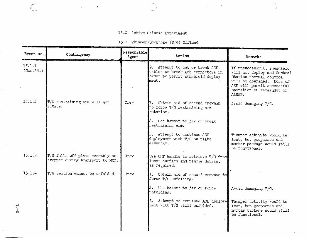
15.1.1 (Cont 'd.)
15.1.2
15.1.3
15.1.4
Contingency
'T/G restraining arm will not rotate.
T/G falls off plate assembly or dropped during transport to MET.
T/G section cannot be unfolded.
15.0 Active Seismic Experiment
15.1 Thumper/Geophone (T/G) Offload
Responsible Agent
Crew
Crew
Crew
Action
9. Attempt to cut or break ASE cables or break ASE connectors in order to permit sunshield deployment.
1. Obtain aid of second crewman to force T/G restraining arm rotation.
2. Use hammer to jar or break restraining arm.
3. Attempt to continue ASE deployment with T/G on plate assembly.
Use UHT handle to retrieve T/G from lunar surface and remove debris, as required.
1. Obtain aid of second crewman to force T/G unfolding.
2. Use hammer to jar or force unfolding.
3. Attempt to continue ASE deployment with T/G still unfolded.
Remarks
If unsuccessful, sunshield will not deploy and Central station thermal control will be degraded. Loss of ASE will permit successful operation of remainder of ALSEP.
Avoid damaging T/G.
Thumper activity would be lost, but geophones and mortar package would still be functional.
Avoid damaging T/G.
Thumper activity would be lost, but geophones and mortar package would still be functional.

1--' \Jl I
w
Event No.
15.1.5
Contingency
~/G sleeve will not lock.
15.0 Active Seismic Experiment
15.1 Thumper/Geophone (T/G) Offload
Responsible Agent Action Remarks
Crew l. Obtain aid of second crewman to force T/G locking.
2. Use hammer to jar or force Avoid damaging T/G. unfolding.
3. Attempt to continue ASE deploy-ment with T/G sleeve unlocked, but exercise caution.

I-' \.n
Event No.
15.2.1
15.2.2
15.2.3
+:-
15.0 Active Seismic Experiment
15.2 Mortar Package Assembly (MPA) Deployment
Contingency
Switch #5 cannot be turned cw to !oFF position.
~ will not engage in MPA carry socket.
~A binds on pins during removal from sunshield.
Responsible Agent
Crew
Crew
Crew
Action
1. Report to MCC.
2. Apply additional force to switch.
3. Do not continue mortar package deployment if unable to turn switch #5.
1. Try to engage second UHT in carry socket.
Remarks
ASE science will be degraded but astronaut safety hazard may exist if mortar package deployment is continued.
2. If UHT engagement fails, deployl MPA antenna is fragile and manually (i.e., using MPA antenna I subject to damage. to lower MPA to lunar surface).
l. Rock MPA and apply additional force.
2. Obtain aid of second crewman.
3. Leave MPA on sunshield and deploy MPA/Central Station as one unit.
4. Use UHT to unreel sufficient cable to permit sunshield deployment.
5. Attempt to cut or break MPA cable or break connector -in order to permit sunshield deployment.
MPA thermal control and science, as well as Central station, will be degraded Thumper activity will not be effected
If unsuccessful, sunshield will not deploy and Central Station thermal control will be degraded. Loss of MPA will permit successful operation of remainder of ALSEP. Thumper activity will not be effected.
t-' Vi
I V1
Event No.
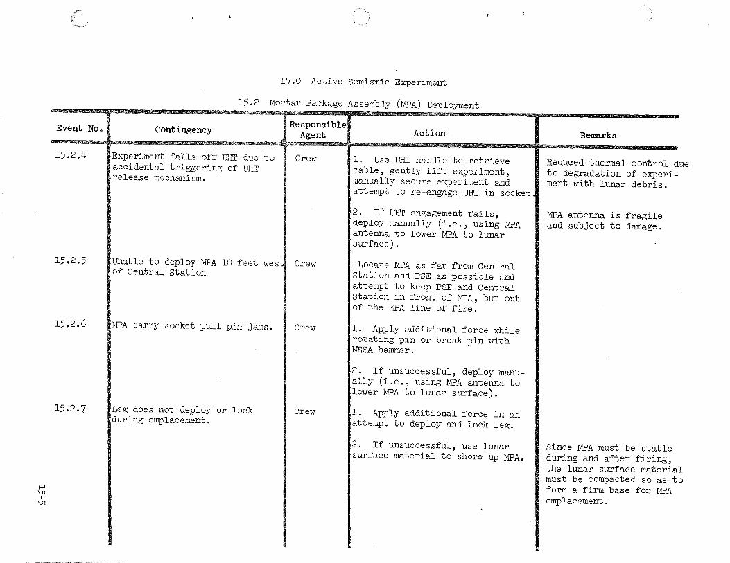
15.2.4
15.2.5
15.2.6
15.2.7
15.0 Active Semismic Experiment
15.2 Mortar Package Assembly (MPA) Deployment
Contingency
Experiment ~alls o~~ UHT due to accidental triggering o~ UHT release mechanism.
Responsible Agent
Crew
Unable to deploy MPA 10 ~eet westl Crew o~ Central Station
MPA carry socket pull pin jams. I Crew
Leg does not deploy or lock during emplacement.
Crew
Action
l. Use UHT handle to retrieve cable, gently li~ experiment, manually secure experiment and attempt to re-engage UHT in socket.
2. I~ UHT engagement ~ails, deploy manually (i.e., using MPA antenna to lower MPA to lunar sur~ace).
Locate MPA as ~ar ~rom Central Station and PSE as possible and attempt to keep PSE and Central Station in ~ront o~ MPA, but out o~ the MPA line of fire.
l. Apply additional force while rotating pin or break pin with MESA hammer.
2. If unsuccessful, deploy manually (i.e., using MPA antenna to lower MPA to lunar surface).
l. Apply additional force in an attempt to deploy and lock leg.
2. If unsuccessful, use lunar surface material to shore up MPA.
Remarks
Reduced thermal control due to degradation of experiment with lunar debris.
MPA antenna is fragile and subject to damage.
Since MPA must be stable during and ~er ~iring, the lunar surface material must be compacted so as to form a firm base ~or MPA emplacement.

1-' \Jl
I 0\
Event No.
15.2.8
15.2.9
15.0 Active Seismic Experiment
15.2 Mortar Package Assembly (MFA) Deployment
Contingency
Safety rod release latch will not release.
Mortar package safe/arm switch jams.
Responsible Agent
Crew
Crew
Action
l. Check hex head of UHT and if damaged,use second UHT.
2. Attempt to overcome lock by forcefully rotating UHT.
3. If unsuccessful, retrieve lanyard and attempt to remove safety rods.
4. If latch will not rotate or lanyard breaks, abandon mortar package deployment.
l. Check hex head of UHT and, if damaged, use second UHT.
2. Apply additional force.
3. If switch will not rotate, abandon mortar package deployment.
Remarks
ASE science will be degraded.
Mortar package will not fire unless both the safe and arm switches are rotated.
1-' \Jl I
---::1
Event No.
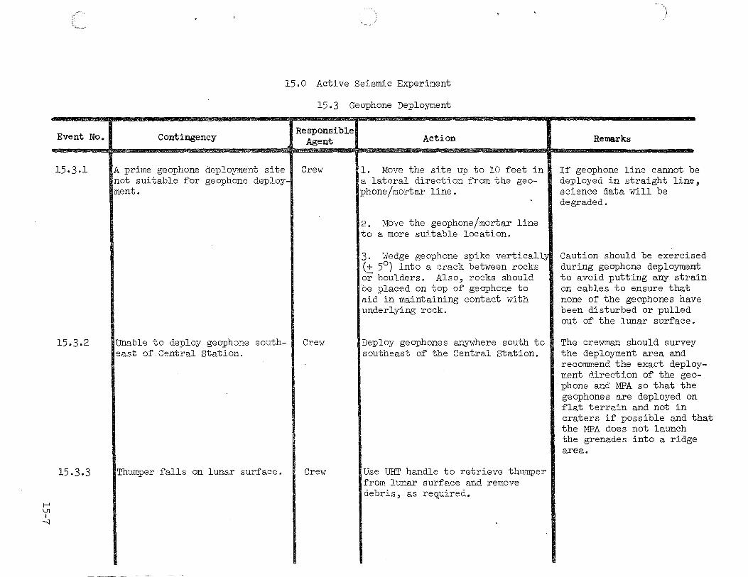
15-3.1
15.3.2
15.3.3
15.0 Active Seismic Experiment
Contingency
A prime geophone deployment site not suitable for geophone deployment.
Unable to deploy geophone southeast of Central station.
Thumper falls on lunar surface.
15.3 Geophone Deployment
Responsible Agent
Crew
Crew
Crew
Action
1. Move the site up to 10 feet in a lateral direction from the geophone/mortar line.
2. Move the geophone/mortar line to a more suitable location.
3. Wedge geophone spike vertically (+ 5°) into a crack between rocks or boulders. Also, rocks should be placed on top of geophone to aid in maintaining contact with underlying rock.
Deploy geophones anywhere south to southeast of the Central Station.
Use UHT handle to retrieve thumper from lunar surface and remove debris, as required.
Remarks
If geophone line cannot be deployed in straight line, science data will be degraded.
Caution should be exercised during geophone deployment to avoid putting any strain on cables to ensure that none of the geophones have been disturbed or pulled out of the lunar surface.
The crewman should survey the deployment area and recommend the exact deployment direction of the geephone and MPA so that the geophones are deployed on flat terrain and not in craters if possible and that the MFA does not launch the grenades into a ridge area.
1-' \.J] I ())
Event No.
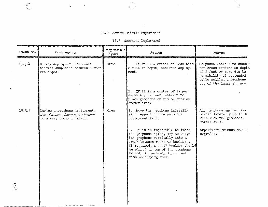
15.3.4
15.3-5
15.0 Active Seismic Experiment
Contingency
During deployment the cable becomes suspended between crater rim edges.
During a geophone deployment, its planned placement changes to a very rocky location.
15.3 Geophone Deployment
Responsible Agent
Crew
Crew
Action
1. If it is a crater of less than 2 feet in depth, continue deployment.
2. If it is a crater of larger depth than 2 feet, attempt to place geophone on rim or outside crater area.
1. Move the geophone laterally with respect to the geophone deployment line.
2. If it is impossible to imbed the geophone spike, try to wedge the geophone vertically into a crack between rocks or boulders. If required, a small boulder should be placed on top of the geophone to hold it securely in contact with underlying rock.
Remarks
Geophone cable line should not cross craters in depth of 2 feet or more due to possibility of suspended cable pulling a geophone out of the lunar surface.
Any geophone may be displaced laterally up to 10 feet from the geophonemortar axis.
Experiment science may be degraded.
1-' \.JJ I
\0
Event No.
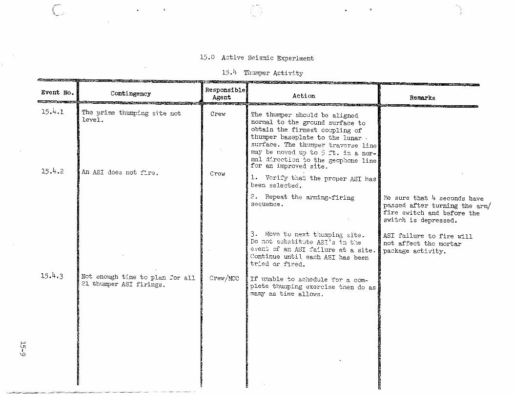
15.4.1
15.4.2
15.4.3
Contingency
The prime thumping site not level.
An ASI does not fire.
Not enough time to plan for all 21 thumper ASI firings.
15.0 Active Seismic Experiment
15.4 Thumper Activity
Responsible Agent
Crew
Crew
Crew/MCC
Action
The thumper should be aligned normal to the ground surface to obtain the firmest coupling of thumper baseplate to the lunar · surface. The thumper traverse line may be moved up to 5 :ft. in a normal direction to the geophone line for an improved site.
1. Verify that the proper ASI has been selected.
2. Repeat the arming-firing sequence.
3. Move to next thumping site. Do not substitute ASI's in the event of an ASI failure at a site. Continue until each ASI has been tried or :fired.
If unable to schedule for a complete thumping exercise then do as many as time allows.
Remarks
Be sure that 4 seconds have passed after turning the arm/ fire switch and before the switch is depressed.
ASI failure to fire will not affect the mortar package activity.

I-' 0'\ I I-'
Event No.
16.1
16.2
16.3
16.0 Suprathermal Ion Detector Experiment/ Cold Cathode Gauge Experiment
Contingency
UHT will not engage in SIDE/CCGE carry socket.
Experiment falls off UHT due to accidental triggering of UHT release mechanism.
Crewman walks too far and jerks Central Station out of alignment
Responsible Agent
Crew
Crew
Crew
~~.
Action
1. Try to engage second UHT in carry socket.
2. If UHT engagement fails, deploy manually by grasping ground screen tube.
l. Use UHT handle to retrieve cable, gently lift experiment, manually secure ground screen tube or leg and attempt to re-engage UHT in socket.
2. If UHT engagement fails, deploy manually by grasping ground screen tube.
l. Carry experiment back toward Central Station to provide slack cable, continue deployment of SIDE/CCGE and realign Central station and check other experiment1 upon return.
2. Check cable and connector at experiment and Central Station interfaces for visible signs of damage.
Remarks

1-' 0'\ I
f\)
Event No.
16.4
16.5
16.6
Contingency
SIDE/CCGE boyd bolt spline will not depress.
SIDE/CCGE boyd bolt will not rotate.
SIDE/CCGE will not come off subpallet.
16.0 Suprathermal Ion Detector Experiment/ Cold Cathode Gauge Experiment
Responsible Agent Action
Crew l. Check hex head of UHT and, if damaged, use second UHT.
2. Use hammer on tap of UHT to · force depression of boydbolt spline.
3. Attempt to overcome spline lock by forcefully rotating UHT.
4. Leave SIDE/CCGE on subpallet and deploy SIDE/CCGE subpallet as one unit.
Crew l. Check hex head of UHT and, if damaged, use second UHT.
2. Leave SIDE/CCGE on subpallet and deploy SIDE/CCGE subpallet as one unit.
Crew l. Ensure all boydbolts have been released.
2. Use UHT to ensure that boyd-bolts have been sprung upward.
3. Leave SIDE/CCGE on subpallet and deploy SIDE/CCGE subpallet.
.
Remarks
Experiment thermal contr and science may be degra
Experiment thermal contr and science may be degra
Experiment thermal contr and science may be degra
1 ed.
l ed.
ol ded.
1--' 0\ I
w
Event No.
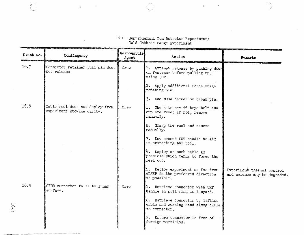
16.7
16.8
16.9
Contingency
Connector retainer pull pin does not release
Cable reel does not deploy from experiment stowage cavity.
SIDE connector falls to lunar surface.
16.0 Suprathermal Ion Detector Experiment/ Cold Cathode Gauge Experiment
Responsible Agent
Crew
Crew
Crew
Action
l. Attempt release by pushing dOW! on fastener before pulling up, using UHT.
2. Apply additional force while rotating pin.
3. Use MESA hammer or break pin.
l. Check to see if boyd bolt and cup are free; if not, remove manually.
2. Grasp the reel and remove manually.
3. Use second UHT handle to aid in extracting the reel.
4. Deploy as much cable as possible which tends to force the reel out.
5. Deploy experiment as far from ALSEP in the preferred direction as possible.
1. Retrieve connector with UHT handle in pull ring on lanyard.
2. Retrieve connector by lifting cable and working hand along cable to connector.
3. Ensure connector is free of foreign particles.
R~ma.rks
Experiment thermal control and science may be degraded.
I-' 0\ I .r::-
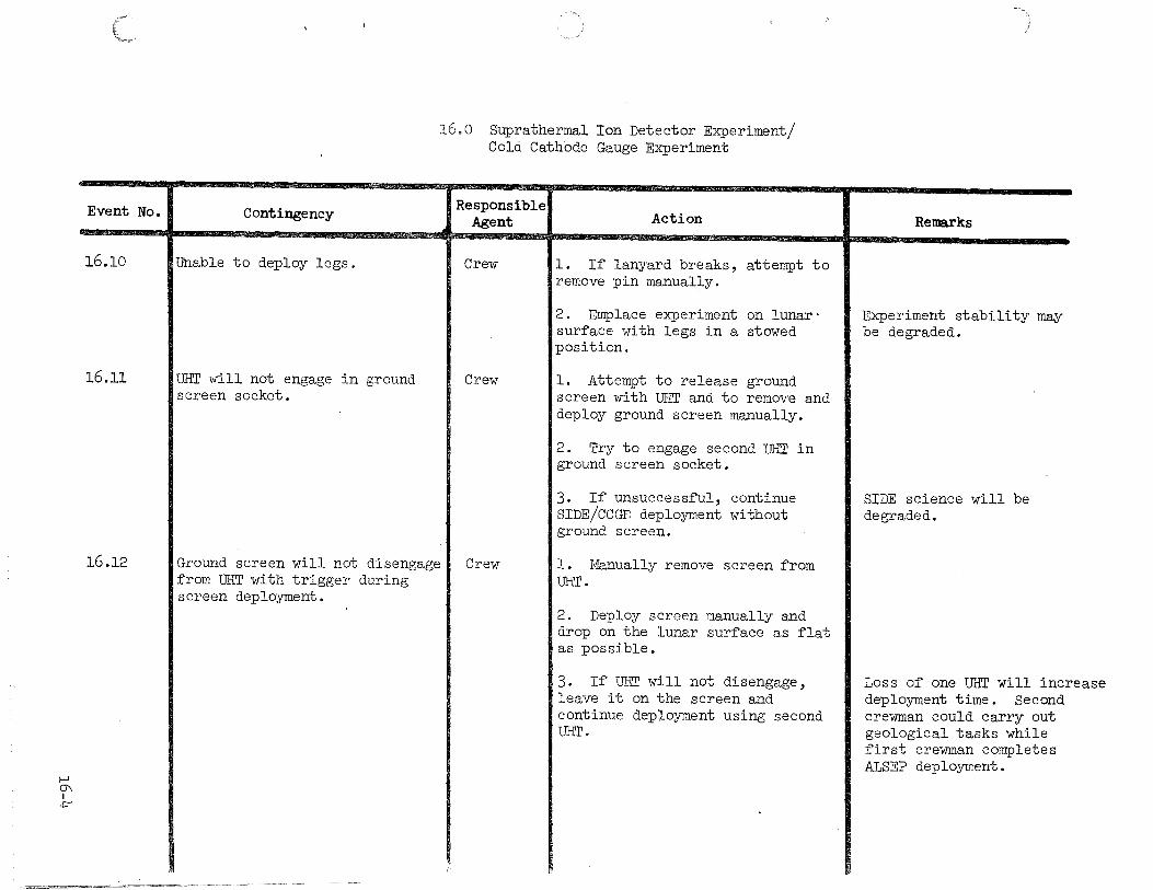
Event No.
16.10
16.11
16.12
Contingency
Unable to deploy legs.
UHT will not engage in ground screen socket.
Ground screen will not disengage from UHT with trigger during screen deployment.
- '~< u< ~~ ~--"""""""'"'==--•-• u -~ •• ~.~. ~=·«-•·-"""''
16.0 Suprathermal Ion Detector Experiment/ Cold Cathode Gauge Experiment
Responsible Agent
Crew
Crew
Crew
Action
l. If lanyard breaks, attempt to remove pin manually.
2. Emplace experiment on lunar· surface with legs in a stowed position.
1. Attempt to release ground screen with UHT and to remove and deploy ground screen manually.
2. Try to engage second UHT in ground screen socket.
3. If unsuccessful, continue SIDE/CCGE deployment without ground screen.
l. Manually remove screen from UHT.
2. Deploy screen manually and drop on the lunar surface as flat as possible.
3. If UHT will not disengage, leave it on the screen and continue deployment using second UHT.
Remarks
Experiment stability may be degraded.
SIDE science will be degraded.
Loss of one UHT will increase deployment time. Second crewman could carry out geological tasks while first crewman completes ALSEP deployment.

1-' 0\ I
\J1
Event No. I Contingency
16.13 ISIDE falls over while emplacing
16.14
16.15
experiment or removing dacron bag.
SIDE leg breaks.
Connector fails to engage to Central Station
16.0 Suprathermal Ion Detector Experiment/ Cold Cathode Gauge Experiment
Responsible1 Action Agent
Crew 11. Attempt to pick up experiment
Crew
by cable after retrieving cable with UHT.
2. Grasp experiment at reel housing and reinsert UHT.
3. Clean experiment with thermal glovP. or through gentle impact.
1. Prop up experiment on RTG cable reel, rock, or other lunar debris.
2. Break off remaining legs and emplace experiment directly on the RTG cable reel or on the surface.
1. Check connectors on cable and Central Station for foreign material and bent pins.
2. Remove or shake out debris.
3. Ensure outer flange is free to travel to the lock position.
4. Attempt to reconnect checking visual indicator (orange ring).
Remarks
Reduced thermal control due to degradation of experiment with lunar debris.
Place ground screen beside experiment (not touching SIDE or CCGE).
Experiment thermal control may be degraded.
1-' 0\ I 0\
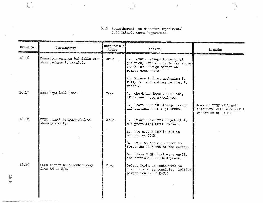
Event No.
16.16
16.17
16.18
16.19
Contingency
Connector engages but falls off when package is rotated.
CCGE boyd bolt jams.
CCGE cannot be removed from stowage cavity.
CCGE cannot be oriented away from 1M or cjs.
16.0 Suprathermal Ion Detector Experiment/ Cold Cathode Gauge Experiment
Responsible Agent
Crew
Crew
Crew
Crew
Action
1. Return package to vertical position, retrieve cable (as above check for foreign matter and remote connectors.
2. Ensure locking mechanism is fully forward and orange ring is visible.
1. Check hex head of UHT and, if damaged, use second UHT.
2. Leave CCGE in stowage cavity and continue SIDE deployment.
1. Ensure that CCGE boydbolt is not preventing CCGE removal.
2. Use second UHT to aid in extracting CCGE.
3. Pull on cable in order to force the CCGE out of the cavity.
4. Leave CCGE in stowage cavity and continue SIDE deployment.
Orient North or South with as clear a view as possible. (Orifice perpendicular to E-W.)
Remarks
Loss of CCGE will not interfere with successful operation of SIDE.

1-' 0\ I
-..;]
Event No.
16.20
16.21
.wo~.-~ ~~·'''''''; __ __;-..:..._
16.0 Suprathermal Ion Detector Experiment/ Cold Cathode Gauge Experiment
Contingency Responsible Action Agent
Dust cover releases when pull Crew Deploy with cover open, but pin is removed. minimize dust contamination.
Dacron dust bag does not come Crew Manually lift experiment and free. remove dacron bag.
Remarks
Experiment thermal contrc 1 science may be degraded.
t-' -.:] I t-'
Event No.
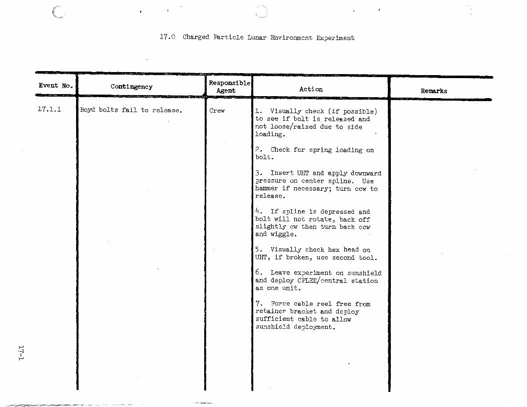
17.1.1
17.0 Charged Particle Lunar Environment Experiment
Contingency
Boyd bolts fail to release.
Responsible Agent
Crew
Action
l. Visually check (if possible) to see if bolt is released and not loose/raised due to side loading.
2. Check for spring loading on bolt.
3. Insert UHT and apply downward pressure on center spline. Use hammer if necessary; turn ccw to release.
4. If spline is depressed and bolt will not rotate, back off slightly cw then turn back ccw and wiggle.
5. Visually check hex head on UHT, if broken, use second tool.
6. Leave experiment on sunshield and deploy CPLEE/central station as one unit.
7. Force cable reel free from retainer bracket and deploy sufficient cable to allow sunshield deployment.
Remarks

t-' .....::I
I 1\)
Event No.
17 .1.2
17.1.3
17.1.4
17.1.5
'··c-c<-==='<"""='~=~=;::,:::...,~-:_.----- ~~
17.0 Charged Particle Lunar Environment Experiment
Contingency
CPLEE carry/removal socket unusable. UHT will not lock in socket.
Swivel socket pull pin jams.
CPLEE dust cover comes off during deployment
Experiment falls off UHT due to accidental triggering of UHT release mechanism.
Responsible Agent
Crew
Crew
Crew
Crew
Action
l. Remove CPLEE manually by grasping leg.
2. Deploy cable from reel while grasring leg.
3. Emplace experiment while grasping thermal plate, using UHT (as required) to aid in emplacing unit upright.
4. Use UHT on thermal plate to align and level unit.
l. Apply additional force while supporting experiment on HTC.
2. If unsuccessful, disengage UHT, emplace experiment by grasping thermal plate, and use UHT to level and align experiment.
Do not reinstall.
l. Use UHT handle to retrieve cable, gently lift experiment, manually secure experiment and attempt to re-engage UHT in socket.
2. If UHT engagement fails, deploy manually (i.e., using CPLEE thermal plate and UHT, as required, to emplace unit upright).
Remarks
Continue deployment.
Reduced thermal control due to degradation of experiment with lunar debris.

1-' --..:] I
w
Event No.
17.1.6
17.1.7
17.1.8
17.0 Charged Particle Lunar Environment Experiment
Contingency
Unable to deploy CPLEE 10 feet northeast of Central Station.
Unable to deploy legs.
Leg breaks off while emplacing the experiment.
Responsible Agent
Crew
Crew
Crew
Action
l. Locate CPLEE as far from Central Station as possible.
2. Attempt to maintain a 10 foot separation between PSE and CPLEE.
3. Attempt to maintain a 10 foot separation between RTG and CPLEE.
l. If lanyard breaks attempt to remove pin manually.
2. Emplace experiment on lunar surface with legs in stowed position.
l. Prop up experiment with core tube, penetrometer, or other lunar debris.
2. Break or fold remaining legs and emplace experiment directly on the lunar surface.
Remarks
Experiment stability will be degraded.
Experiment thermal control may be degraded.

1--' ()) I
1--'
Event No.
18.1.1
Contingency
Boyd bolt(s) fail to release.
18.0 Central Station
Responsible Agent
Crew
Action
1. Visually check (if possible) to see if bolt is released and not loose/raised due to side loading.
2. Check for spring loading on bolt.
3. Insert UHT and apply downward pressure on center spline. Use hammer if necessary; turn ccw to release.
4. If spline is depressed and bolt will not rotate, back off slightly cw then turn back ccw and wiggle.
5. Visually check hex head on UHT, if broken, use second tool.
6. Engage UHT in Subpackage #1 temporary stowage socket and use UHT as a lever to raise sunshield.
7. Leave sunshield in stowed condition and attempt to gain access to antenna mass bracket.
8. If unsuccessful, mount antenna aiming mechanism on sunshield.
Remarks
Central Station thermal control will be degraded.
Antenna aiming accuracy will be degraded.
t--' ()) I f\)
Event No.
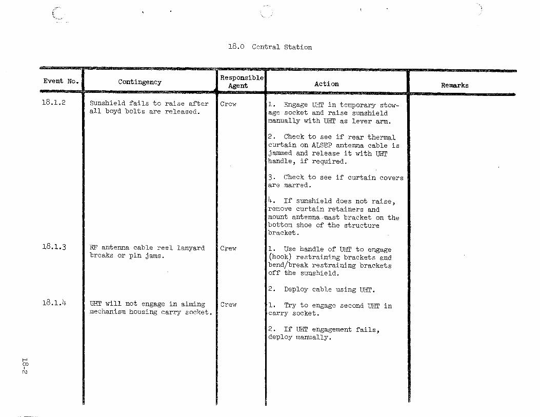
18.1.2
18.1.3
18.1.4
18.0 Central Station
Contingency
Sunshield fails to raise after all boyd bolts are released.
RF antenna cable reel lanyard breaks or pin jams.
Responsible Agent
Crew
C:rew
UHT will not engage in aiming I Crew mechanism housing carry socket.
Action
l. Engage UHT in temporary stowage socket and raise sunshield manually with UHT as lever arm.
2. Check to see if rear thermal curtain on ALSEP antenna cable is jammed and release it with UHT handle, if required.
3. Check to see if curtain covers are marred.
4. If sunshield does not raise, remove curtain retainers and mount antenna mast bracket on the bottom shoe of the structure bracket.
1. Use handle of UHT to engage (hook) restraining brackets and bend/break restraining brackets off the sunshield.
2. Deploy cable using UHT.
1. Try to engage second UHT in carry socket.
2. If UHT engagement fails, deploy manually.
Remarks

t-' (X) I
w
Event No.
18.1.5
18.0 Central Station
Contingency Responsible Agent
Aiming mechanism boyd bolts fail I Crew to release.
Action
1. Visually check (if' possible) to see if bolt is released and not loose/raised due to side loading.
2. Check for spring loading on bolt.
3. Insert mrr and apply downward pressure on center spline. Use hammer if necessary; turn ccw to release.
4. If' spline is depressed and bolt will not rotate, back off slightly cw, then turn back ccw and wiggle.
5. Visually check hex head on UHT, if broken, use second tool.
6. If' unsuccessful, break housing off mounting legs with side loading to gain access to aiming mechanism.
7. If unable to gain access to aiming mechanism, mount antenna on Central Station sunshield brackets and point antenna toward earth.
Remarks
Antenna aiming accuracy will be degraded.

!-' CP I +='
Event No.
18.1.6
18.1. 7
18.1.8
18.1.9
18.0 Central Station
Contingency
Antenna mast binds on subpallet taper fitting.
Aiming mechanism housing will not come off subpallet.
Responsible Agent
Crew
Crew
Antenna mast bracket on Central I Crew Station covered with. lunar debris.
Aiming mechanism falls out of housing on lunar surface.
Crew
Action
Stand on edge of subpallet and rotate mast while applying additional lifting force on lower half.
1. Ensure both boyd bolts have been released.
2. Use UHT to ensure that boyd bolts have been sprung upward.
3. If unsuccessful, use MESA hammer to break housing off mounting legs in order to gain access to aiming mechanism.
4. If unable to gain access to aiming mechanism, mount antenna on Central Station sunshield.
Clear area with lunar boot or use UHT to probe or jar bracket and free it of debris.
Retrieve mechanism with UHT handle and shake off debris. Clean taper fitting with glove.
Remarks
Antenna aiming accuracy will be degraded.
Reduced operational capability or jamming of the gears and pivot points is possible due to degradations of the aiming mechanism surfaces with lunar debris.
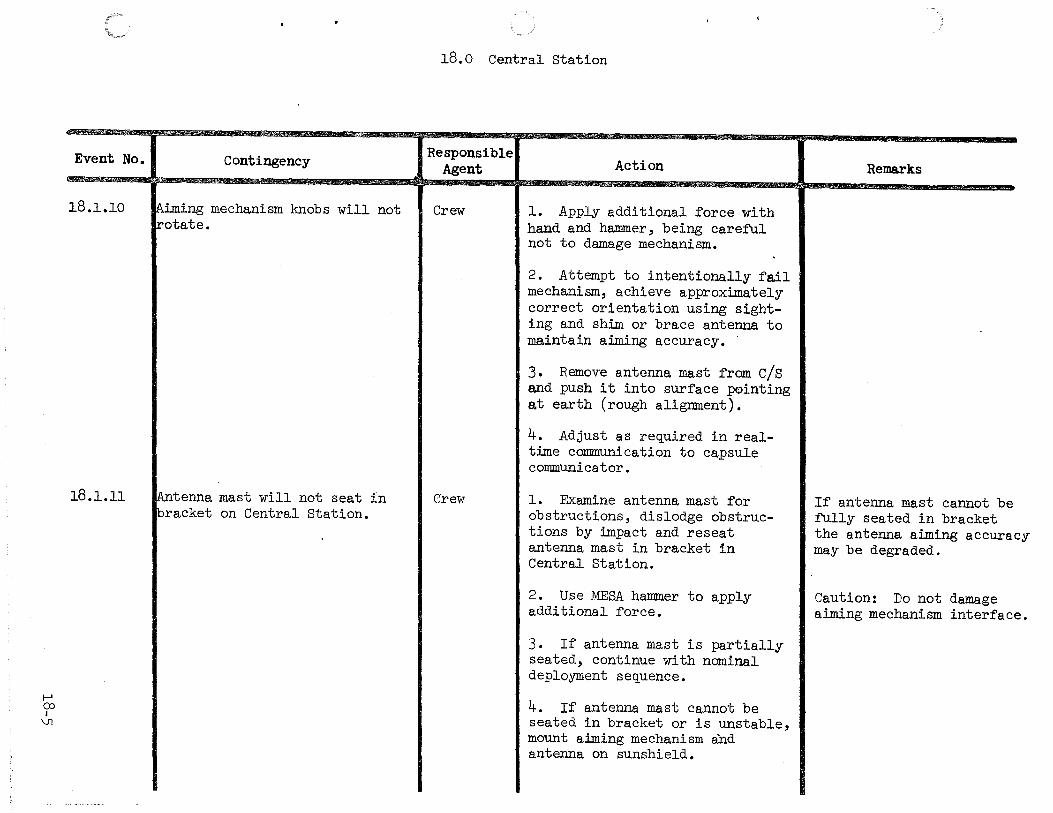
1--' ()) I
\Jl
Event No.
18.1.10
18.1.11
Contingency
!Aiming mechanism knobs will not !rotate.
~tenna mast will not seat in ~racket on Central Station.
18.0 Central Station
Responsible Agent
Crew
Crew
Action
1. Apply additional force with hand and hammer, being careful not to damage mechanism.
2. Attempt to intentionally fail mechanism, achieve approximately correct orientation using sighting and shim or brace antenna to maintain aiming accuracy.
3. Remove antenna mast from cjs and push it into surface pointing at earth (rough alignment).
4. Adjust as re~uired in realtime communication to capsule communicator.
1. Examine antenna mast for obstructions, dislodge obstructions by impact and reseat antenna mast in bracket in Central Station.
2. Use M~SA hammer to apply additional force.
3. If antenna mast is partially seated, continue with nominal deployment se~uence.
4. If antenna mast cannot be seated in bracket or is unstable, mount aiming mechanism and antenna on sunshield.
Remarks
If antenna mast cannot be fully seated in bracket the antenna aiming accuracy may be degraded.
Caution: Do not damage aiming mechanism interface.
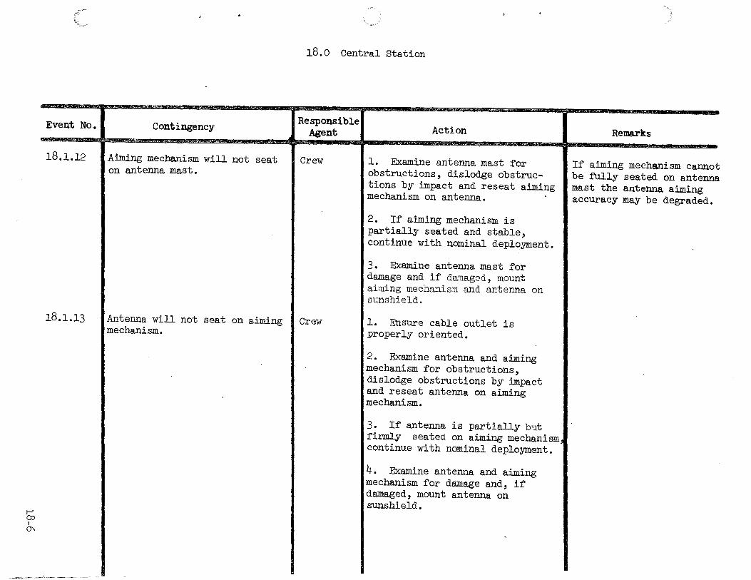
1-' ()) I 0'\
Event No.
l8.l.l2
l8.l.l3
Contingency
Aiming mechanism will not seat on antenna mast.
Antenna will not seat on aiming mechanism.
18.0 Central Station
Responsible Agent
Crew
Crew
Action
l. Examine antenna mast for obstructions, dislodge obstructions by impa.ct and reseat aiming mechanism on antenna.
2. If aiming mechanism is partially seated and stable, continue with nominal deployment.
3. Examine antenna mast for damage and if damaged, mount aiming mechanism and antenna on sunshield.
l. Ensure cable outlet is properly oriented.
2. Examine antenna and aimlng mechanism for obstructions, dislodge obstructions by impact and reseat antenna on aiming mechanism.
3. If antenna is partially but firmly seated on aiming mechanism continue with nominal deployment.
4. Examine antenna and aiming mechanism for damage and, if damaged, mount antenna on sunshield.
Remarks
If aiming mechanism cannot be fUlly seated on antenna mast the antenna aiming accuracy may be degraded.

18.0 Central Station
:vent No.I ~7" w•
Contingency Responsible
Action Remarks Agent '\···Yf '•''
18.1.14 ALSEP deployment time becomes Crew l. If antenna is level and constrained. aligned, actuate the RTG shorting
switch and ASTRO switch No. l.
2. If antenna is not aligned or level and there will be a second EVA, do not actuate these switches.
3. If no second EVA, level and align as accurate as possible and actuate switches.
4. Do not activate any switches if none of the experiments have been deployed and no second EVA.
1--' ():) I
-.;:)
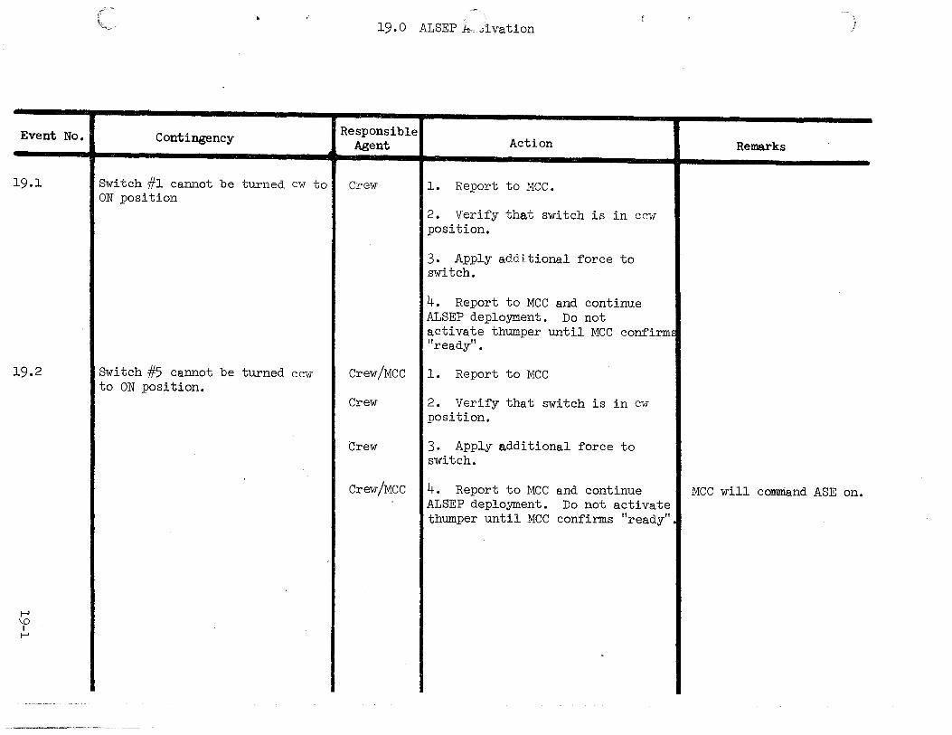
Event No.
19.1
19.2
t--' \0 I
t--'
Contingency
Switch #1 cannot be turned cw to ON position
Switch #5 cannot be turned ccw to ON position.
19.0 ALSEP A vlvation
Responsible Agent
Crew
Crew/MCC
Action
1. Report to MCC.
2. Verify that switch is in ccw position.
3. Apply additional force to switch.
4. Report to MCC and continue ALSEP deployment. Do not activate thumper until MCC confirm~ "ready".
1. Report to MCC
Crew 12. Verify that switch is in cw position.
Crew I 3. Apply additional force to switch.
Remarks
Crew/MCC 14. Report to MCC and continue I MCC will comniand ASE on. ALSEP deployment. Do not activate thumper until MCC confirms "ready" •I

1-' \0 I
1\)
Event No.
19.3
Contingency
Central Station contingency antenna alignment.
19.0 ALSEP Activation
Responsible Agent Action Remarks
Crew l. Point antenna in general direction of earth.
2. Adjust antenna pointing angle in small increments, stepping back after each adjustment to avoid distortion of antenna beam pattern
3. Perform required offsets under MCC direction.

1-' '-0 I
w
Event No.
19.4
Contingency
Turn-on of ALSEP transmitter
19.0 ALSEP Activation
Responsible Agent
Crew/MCC
Action
1. Astronaut standby for manual turn-on of ALSEP transmitter.
2. Actuate ALSEP back-up switch No. 2 with following functions:
a. Select Transmitter B. b. Turn on Transmitter. c. Reset receiver circuit
breaker. d. Select and turn on data
processor Y.
3. Advise MCC via voice link back-up switch No. 2 has been actuated.
4. Acknowledge MCC transmitter message via voice link.
5. If transmitter is not funct~ ing, actuate ALSEP back-up switch No. 1, permitting PCU to operate on marginal voltage output of RTG.
6. If transmitter is still not
Remarks
Initiate command CD-4 (octal 015) "Transmitter B Select." If no response, advise astronaut via voice link to turn on transmitter
Acknowledge turn-on of transmitter by recep~ion of RF signal from ALSEP.
Advise astronaut via voice link whether transmitter is functioning •.
Acknowl~dge back-up sWi~ch No. 3 actuation via voice link.
functioning, actuate back-up switch No. 3, energizing all experiments, sequentially. Confirm power turn-on by
MCC via voice link thatltelemetry indication (Channe 7. Advise switch No. 3 has been actuated. 12 and 14) .
Advise astronauts that all experiments ha~e been turnec on via voice link.
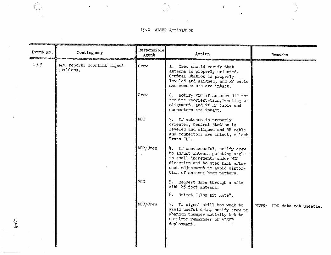
1-' \0
I +
Event No.
19.5
·"'
Contingency
MCC reports downlink signal problems.
19.0 ALSEP Activation
Responsible Agent Action Remarks
Crew l. Crew should verify that antenna is properly oriented, Central Station is properly leveled and aligned, and RF eable and cor~ectors are intact.
Crew 2. Notify MCC if antenna did not require reorientation,leveling or alignment, and if RF cable and connectors are intact.
MCC 3. If antenna is properly oriented, Central Station is leveled and aligned and RF cable and connectors are intact, select Trans "B".
MCC/Crew 4. If unsuccessful, notify crew to adjust antenna pointing angle in small increments under MCC direction and to step back after each adjustment to avoid distor-tion of antenna beam pattern.
MCC 5. Request data through a site with 85 foot antenna.
6. Select "Slow Bit Rate".
MCC/Crew 7. If signal still too weak to NOTE: HBR data not useab yield useful data, notify crew to
le.
abandon thumper activity but to complete remainder of ALSEP deployment.
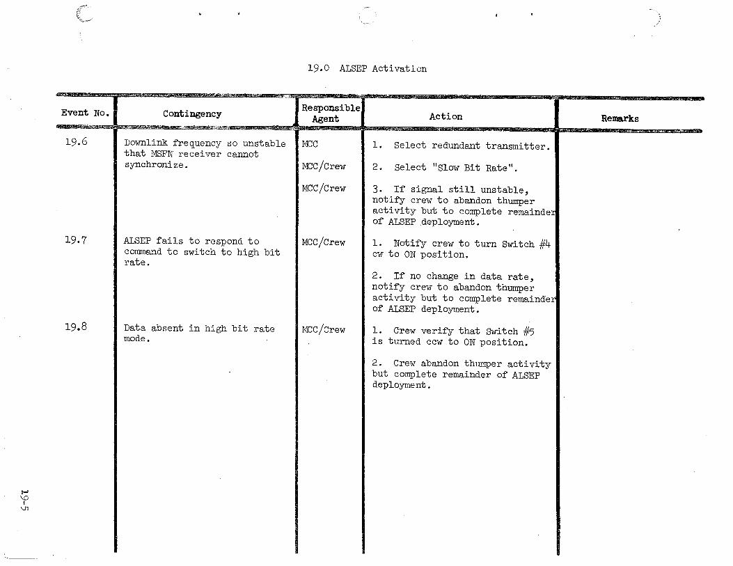
t-' \0 I
\Jl
Event No.
19.6
19.7
19.8
;:
Contingency "''""''' .. ,
Downlink frequency so unstable that MSFN receiver cannot synchronize.
ALSEP fails to respond to command to switch to high bit rate.
Data absent in high bit rate mode.
19.0 ALSEP Activation
Responsible Agent Action Remarks
MCC l. Select redundant transmitter.
MCC/Crew 2. Select "Slow Bit Rate".
MCC/Crew 3. If signal still unstable, notify crew to abandon thumper activity but to complete remainder of ALSEP deployment.
MCC/Crew l. Notify crew to turn Switch #4 cw to ON position.
2. If no change in data rate, notify crew to abandon thumper activity but to complete remainder of ALSEP deployment.
MCC/Crew l. Crew verify that SWitch #5 is turned ccw to ON position.
2. Crew abandon thumper activity but complete remainder of ALSEP deployment.

20.0 CSM/LM 8-Band Transponder
:<¥;,~
Event No. Contingency Responsible Action Remarks Agent
20.1 No 1M docking. MCC 1. If CM lunar orbit mission, proceed with CM portion of experiment only.
2. If CM lunar flyby mission, scrub all experiment items.
1\) 0 I
1-'
,,,,,,

Event No.
21.1
21.2
21.3
21.4
21.5
1\) 1-' I 1-'
..
21.0 Down-Link Bi-Static Radar Observation of the Moon
Contingency
VHF antenna failure.
VHF ground equipment failure
Not enough time for completion of both phases.
I S-band 210' dish at Goldstone not available.
I Unable to determine S-band antenna pointing.
I I
Responsible1 Action Agent
Crew I Switch to other VHF antenna. Position S/C so that selected antenna faces lunar surface.
Crew I Scrub VHF position of experiment.
Crew I Try to do one complete phase.
Crew I Scrub S•band portion of experiment.
Crew I Scrub S-band portion of experiment.
Remarks
Assumes one antenna failure.
Special VHF ground equipment located at Stanford University.
Phase A - From Earth-Moon centerline traversing to Horizon (LOS).
Phase B - From horizon (AOS) to Earth-Moon centerline.
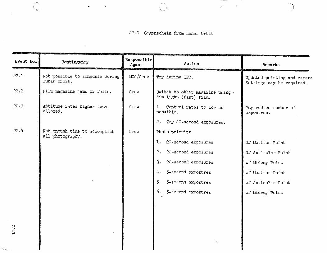
Event No.
22.1
22.2
22.3
22.4
1\) 1\) I t-'
Contingency
Not possible to schedule during lunar orbit.
Film magazine jams or fails.
Attitude rates higher than allowed.
Not enough time to accomplish all photography.
22.0 Gegenschein from Lunar Orbit
Responsible1
Action Agent
MCC/Crew I Try during TEC.
Crew
Crew
Crew
Switch to other magazine using dim light (fast) film.
l. Control rates to low as possible.
2. Try 20-second exposures.
Photo priority
l. 20-second exposures
2. 20-second exposures
3. 20-second exposures
4. 5-second exposures
5. 5-second exposures
6. 5-second exposures
Remarks
Updated pointing and camera Settings may be required.
May reduce number of exposures.
Of Moulton Point
Of Antisolar Point
of Midway Point
of Moulton Point
of Antisolar Point
of Midway Point
23.0 ABBREVIATIONS AND ACRONYMS
ABBREVIATIONS
ALSEP ASI
CCGE CDR CPLEE esc CSM
DRT
EMU EVA
FTT
GASC
HTC
LEC LM LMP LRRR/LR3
MCC MESA MPA MSSC
PCU PDR PSE
RTG
SEQ/Bay SESC SRC swc
TM
UHT
DEFINITIONS
Apollo Lunar Surface Experiment Package Apollo Standard Initiator
Cold Cathode Gauge Experiment Commander Charged Particle Lunar Environment Experiment Contingency Sample Container Command Service Module
Dome Removal Tool
Extravehicular Mobility Unit Extravehicular Activity
Fuel Transfer Tool
Gas Analysis Sample Container
Hand Tool Carrier
Lunar Equipment Conveyer Lunar Module Lunar Module Pilot Laser Ranging Retro-Reflector
Mission Control Center Modularized Equipment Stowage Assembly Mortar Package Assembly Magnetic Shield Sample Container
Power Control Unit Power Dissipation Resistor Passive Seismic Experiment
Radioisotope Thermoelectric Generator
Scientific Equipment Bay Special Environmental Sample Container Sample Return Container Solar Wind Composition
Telemetry
Universal Handling Tool
23-1

Top Related