


Languages
Pages
Legal

Role of Surface Geometric Patterns and Parameters in the Dispersion
Relations of Spoof Surface Plasmon Polaritons at Microwave Frequency
Rana Sadaf Anwar, Lingfeng Mao, and Huansheng Ning*
School of Computer and Communication Engineering
University of Science and Technology Beijing, Beijing, 100083, China
[email protected], [email protected], *[email protected]
Abstract ─ Spoof surface plasmon polaritons (SSPPs)
can be excited using geometric shapes on conducting
surfaces in microwave (MW) regime. They are eminent
as compared to the conventional microstrip (MS)
transmission lines, due to their better efficiency and
compactness in high density and high-speed circuitry. In
this work, we compare normalized dispersion curves
(DCs) of different groove shapes engineered on the
planar metallic strip with the variation of geometric
parameters of the structure, which are obtained by
Eigen-mode solver of ANSYS’s HFSS. It is found the
dispersion characteristics are determined by the shape
and the asymptotic frequency can finely be tuned
through the geometric parameters. All DCs deviate
further from the light line indicating slow propagation
of SSPPS. The performance of rectangular grooves
is clearly outstanding; however, the circular grooves
behave comparably better than Vee-groove. Further, a
low pass plasmonic filter has been proposed with semi-
circular gradient subwavelength grooves designed on a
planar metallic strip with transition sections to match
both the impedance and momentum of MS line and
the plasmonic waveguide. Results of S-parameters and
magnitude of electric field distributions show excellent
transmission efficiency from fast guided wave to slow
SSPPs. It is also observed that the confinement of such
surface waves is dependent on the geometric parameters
which can be useful in plasmonic structure engineering
and fine-tuning the cutoff frequencies, hence posing a
new prospect for advanced plasmonic integrated devices
and circuits.
Index Terms ─ Microwave, plasmonics, surface plasmon
polaritons, sub-wavelength, surface geometry.
I. INTRODUCTION Manipulating the electromagnetic waves through
subwavelength apertures has invoked the interest of many researchers and formed the basis of extensive investigation in the field of plasmonics, after the discovery of extraordinary transmission through nanohole arrays in the metallic film by Ebbesen et al. [1]. Applications of
plasmonics are focused in diverse fields such as Surface-Enhanced Raman Scattering [2], surface plasmon resonance sensors [3], and surface plasmon spectroscopy systems [4]. Numerous areas have been flourished by plasmonics, ranging from chemistry, biology, physics, and material science [5-7].
Surface plasmon polaritons (SPPs) are the self-sustaining and propagating electromagnetic (EM) waves, which are provoked on the metal-dielectric interface in the optical regime where the incident energy is highly accumulated across the edges of the periodic corrugations in metal film and so it can easily cross through [1, 8]. SPPs have much smaller wavelength as compared to the light of incidence. Once SPPs are excited, they travel in a direction parallel to the metal-dielectric interface. They are evanescent by nature, and so they decay exponentially along the perpendicular direction of the metal-dielectric interface. The propagation of SPPs can be manipulated through couplers and waveguides. However, there is a mismatch in momentum between SPPs and free space photon of light, due to bound nature of SPPs, which is evident by k-vector differences on dispersion diagrams. This mismatch depends on the surface nature of the structure. Momentum matching can be achieved by scattering of EM waves through the use of methods such as using high index prism, evanescent field coupling and grating coupling [9, 10].
Free carriers have a major contribution to the dielectric function which is of significant importance in metals and semiconductors. A classical conductivity model based on standard equations for electron motion in an electric field is referred to as the Drude model and presents the straightforward theory for the optical parameters. The dielectric constant of conducting metal film is related to plasma frequency and is given by Drude’s model as:
2
2( ) 1
P
Mi
, (1)
2
0
Pne
m. (2)
Here, ωP defines the plasma frequency of the metal,
ω is the angular frequency of the incident electromagnetic
wave, Ԑ0 is the permittivity of free space, Г is the
ACES JOURNAL, Vol. 34, No. 1, January 2019
Submitted On: June 29, 2018 Accepted On: December 25, 2018 1054-4887 © ACES
172
scattering rate of electron motion, while n is the free
carrier density, e and m are the charge and the mass of
an electron, respectively. Usually, metals have a higher
density of free electrons; therefore, their ωP is higher. The
dispersion relation for light in a metal bounded to a
dielectric layer is derived by solving Maxwell’s equations
by substituting dielectric constant relation (1):
0
( )
I M
x
I M
k k , (3)
The in-plane wavevector kx, named as the momentum of SPPs (also represented by β), is a function of angular frequency [10] and is the wavevector in the plane of the un-textured surface along which it propagates. k0 is the free-space wavevector. ԐI and ԐM are the frequency dependent complex dielectric functions (relative permittivity) of adjacent dielectric film and metal, respectively. It has been noticed at ω<ωP, the condition kx>k0 is satisfied. Therefore, SPP’s field decays exponentially with the distance from the surface, along with the perpendicular direction of the metal-dielectric interface. The occurrence of this field is temporary by nature, and so it is limited to the surface of the metal. The field confinement of SPPs is tighter for higher values of wavevector.
In contrast to the optical regime, the metal behaves
as a perfect electric conductor (PEC) at lower frequencies.
To overcome this problem, properties similar to the SPPs
have been achieved by using plasmonic metamaterials
proposed by many researchers by use of subwavelength
textured structures after the proposal by Pendry et al.
[11]. Different shapes of metallic subwavelength aperture
arrays, grooves or single slit structures are being explored,
working at the microwave to terahertz regime. Such
textured surfaces support the propagation of surfaces
waves also called as spoof SPPs (SSPPs) [12]. A lower
working frequency of SPPs to gigahertz can be achieved
through surface decorations, such as holes [13], metallic
apertures [14, 15], rectangular gratings [16, 17], triangular
corrugations [18], T-grooves [19] and elliptical grooves
[20]. A review of recent progress on exciting SPPs
in microwave (MW) and terahertz (THz) regimes by
incorporating various subwavelength corrugated shapes
on conductive or metal surfaces has been presented in
[21]. It has been known that propagating EM waves on
the surface of a structure have a propagation constant given as γ=α+jβ, where α represents the attenuation constant and β is the phase constant. It is known that the confinement of SSPPs mainly depends on the β (wavenumber along the direction of propagation kx) which is related to k0 by a related parameter of the decay constant (along tangential direction) and is given by [22]:
2 2
0 t xk k , (4)
Here, k0=2 /λ. It can be observed from (4) that the level of field confinement is positively related to the
wavenumber in the direction of propagation. The analysis presented in this paper gives a
comparison of the dispersion curves by engineering different type of surface textures as the phenomenon of exciting SSPPs has been proved in earlier investigations on the planar conducting layer with surface decorations. We consider three geometric structure shapes to excite the SSPPs and analyze their effects on DCs (ω–β relations) in detail by performing comparisons of their dispersion and confinement capacities. It is proved that basic unit cell geometry can play a prominent role in SSPPs excitation. For example, we find that they are highly bound to the surface with rectangular corrugations and have a lower asymptotic frequency as compared to surfaces with circular/V-groove patterns. Due to the lower value of momentum mismatch for circular and V-groove structures, they are closer to the wave vector of free space (k0). Therefore, surface texture engineering can cause prominent influence in applications of planar plasmonic metamaterials and nanophotonics.
II. DISPERSION RELATIONS AND
ANALYSIS We investigate the dispersion characteristics of
SSPPs for planar metallic structures having different etched geometries by the Eigen mode solver of the commercial software package, ANSYS’s High Frequency Structure Simulator (HFSS) which uses Finite element method (FEM). The TM-polarized waves are propagating in the x-direction which is along the corrugated metal plate structures as depicted in Fig. 1. The properties of SSPPs modes are primarily controlled by the geometric parameters of the structure. To perform a comparison; the structure is composed of a thin metallic strip (parameter ‘t’ for thickness) on top of a dielectric substrate with a thickness of 2.65mm, the relative dielectric constant of 2.2 and loss tangent of 0.0009. We denote the width and depth of grooves by ‘w’ and ‘h’ respectively while the period of the structure is ‘P’ and height of the metallic strip is ‘H’ for all grooved structures as shown in Fig. 1. Firstly, to study the dispersion behavior, we start with circular groove and vary the height ‘h’ from 5mm to 7.5mm while ‘P’, ‘w’ and ‘H’ are kept constant at 20mm, 7.5mm, and 8mm respectively. The dispersion curves so obtained for the fundamental propagating mode are plotted in Fig. 2. The continuous black curve is the light line (LL), and the black dashed curve shows the DC of microstrip (un-textured) structure.
It is clear from Fig. 2 that all the dispersion curves
deviate from the light line and reach a constant
asymptotic frequency at the edge of the Brillouin zone
which is the region in k-space which can be occupied by
low "k" electrons without being affected by diffraction
phenomenon. The DCs for SSPPs show that the
asymptotic frequency is dominantly related to the depth
of the grooves. As the depth of the grooves increases,
the asymptotic frequency gets lower (higher β), which
ANWAR, MAO, NING: SURFACE GEOMETRIC PATTERNS AND PARAMETERS IN THE DISPERSION RELATIONS 173

implies the stronger confinement of surface waves in
the circular groove strip. As the depth of grooves is
decreased, the in-plane wave vector gradually approaches
k0. Therefore, the SSPPs are strongly bounded for higher
in-plane wavevector and vice versa. At low frequency
limit, the SSPPs dispersion curves are closer to the light
line. The metal acts as a perfect electric conductor (PEC)
in this regime (comprises of microwave frequency
region). The dispersion relation for this limit is reduced
to kx=k0 and corresponds to EM wave propagating
parallel to the interface in a dielectric layer. That is the
reason, at low frequency, the SSPPs behave like light.
Fig. 1. Unit cell of a SSPPs structure with geometric
parameters characterizing the groove geometry for: (a)
Circular (Cir) groove, (b) Rectangular (Rec) groove, and
(c) V (Vee) groove.
At high frequency range, as it approaches surface
plasmon frequency, the propagation constant of SSPPs is
greater than that of vacuum, which implies that they are
more strongly confined. For example, in Fig. 2, when
h=5mm, the asymptotic frequency reaches 4.3GHz, the
dispersion approaches SSPP modes which propagate
more gradually and localize more tightly on the surface
of the semi-circular grooved metal plate.
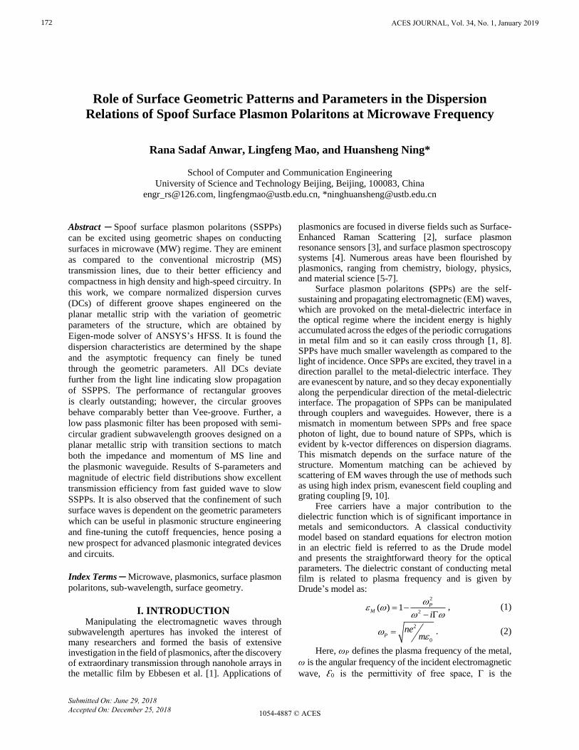
To make a comparison among SSPPs structures with
differently patterned grooves, we consider the unit cells
as shown in Figs. 1 (a-c), to perform simulations. All the
grooved patterns have the same geometric parametric
values as for Fig. 2 along with h=7.5mm, and the
dispersion relations are shown in Fig. 3. It is prominent
that geometric shape and their parameters play a major
role in determining the dispersion properties. All
the dispersion curves deviate from the light line and
increasingly become steady until they reach their
asymptotic frequencies. Although all of them pose a
similar trend, these curves exhibit different frequency
band behavior for different grooves patterns. Noticeably,
the asymptotic frequency of the rectangular groove
structure is lower than other types, confirming that it has
strongest field confinement of SSPPs on the surface.
Circular groove dispersion behavior is better than Vee
groove as it has a comparatively lower asymptotic
frequency. Single sided rectangular grooves structure on a
dielectric substrate can be assumed as similar to an array of coplanar strip aligned vertically, and the dispersion
relation of such a corrugated MS can be found by (5) as
given in [23] where k0 is replaced by 0eff k to estimate
the asymptotic frequency:
2 2
0 0 0( ) tan( ) x eff eff eff
wk k k k h
P, (5)
Ԑeff is the effective permittivity where the SSPPs
propagate and can be estimated by (6):
'
1
'
1
1 ( ) ( )1
2 ( ) ( )
I
eff
K k K k
K k K k, (6)
Fig. 2. Dispersion relations of SSPPs for the fundamental
mode with varying circular groove depths.
Here, K represents the whole elliptic integral of
the first type, kw/P, ' 21 k k , ' 2
1 11 k k , and
1
sinh4
sinh4
wt
kP
t
.
Explicit effect of structure parameters on the dispersion characteristics can be understood through an analysis, by changing the parametric values. The corrugation size significantly impacts on the SSPPs characteristics. Higher is the value of groove width ‘w’ and height ‘h’, lower is the asymptotic frequency and therefore stronger is the field confinement [24].
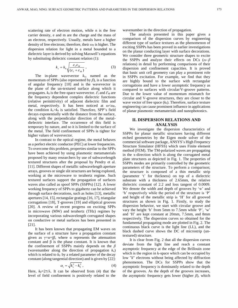
Figure 4 depicts the effect of groove width ‘w’ on the dispersion curves of different SSPPs structures. Width ‘w’ of all three types of structures is reduced to 1mm comparatively as used in the previous analysis (7.5mm) shown in Fig. 3. A comparison of DCs for circular and rectangular grooved structures respectively is given in Fig. 5, in which groove width is reduced from 7.5mm to 1mm. It is seen that the asymptotic frequency depends prominently on the groove width and decreases when ‘w’ increases, indicating that this geometric parameter notably affects the confinement ability of the surface waves.
0
1E+09
2E+09
3E+09
4E+09
5E+09
6E+09
7E+09
8E+09
0 0.2 0.4 0.6 0.8 1
Fre
qu
ency
(H
z)
βP/π
h=5
h=6
h=7
h=7.5
MS
LL
Unit=mm
ACES JOURNAL, Vol. 34, No. 1, January 2019174
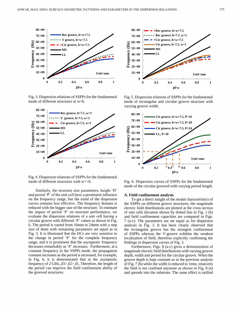
Fig. 3. Dispersion relations of SSPPs for the fundamental
mode of different structures at w=h.
Fig. 4. Dispersion relations of SSPPs for the fundamental
mode of different structures with w<<h.
Similarly, the structure size parameters, height ‘H’
and period ‘P’ of the unit cell have a prominent influence on the frequency range, but the trend of the dispersion curves remains less effective. The frequency domain is reduced with the bigger size of the structure. To estimate the impact of period ‘P’ on structure performance, we evaluate the dispersion relations of a unit cell having a circular groove with different ‘P’ values as shown in Fig. 6. The period is varied from 16mm to 24mm with a step size of 4mm with remaining parameters set equal as in Fig. 3. It is illustrated that the DCs are very sensitive to the change in period ‘P’ for the complete frequency range, and it is prominent that the asymptotic frequency decreases remarkably as ‘P’ increases. Furthermore, at a constant frequency in the SSPPs mode, the propagation constant increases as the period is increased, for example, in Fig. 6, it is demonstrated that at the asymptotic frequency of 2 GHz, β3> β2> β1. Therefore, the length of the period can improve the field confinement ability of the grooved structures.
Fig. 5. Dispersion relations of SSPPs for the fundamental
mode of rectangular and circular groove structure with
varying groove width.
Fig. 6. Dispersion curves of SSPPs for the fundamental
mode of the circular grooved with varying period length.
A. Field confinement analysis To get a direct insight of the modal characteristics of
the SSPPs on different groove structures, the magnitude electric field distributions are plotted at the cross section of unit cells (location shown by dotted line in Fig. 1 (b) and field confinement capacities are compared in Figs. 7 (a-c). The parameters are set equal as for dispersion analysis in Fig. 3. It has been clearly observed that the rectangular groove has the strongest confinement of SSPPs whereas the V-groove exhibits the weakest localization of field, therefore explicitly confirming the findings in dispersion curves of Fig. 3.
Furthermore, Figs. 8 (a-c) gives a demonstration of magnitude electric field distributions with varying groove depth, width and period for the circular groove. When the groove depth is kept constant as in the previous analysis of Fig. 7 (b) while the width is reduced to 1mm, relatively the field is not confined anymore as shown in Fig. 8 (a) and spreads into the substrate. The same effect is ratified
0
1E+09
2E+09
3E+09
4E+09
5E+09
6E+09
7E+09
8E+09
0 0.2 0.4 0.6 0.8 1
Fre
qu
ency
(H
z)
βP/π
Rec groove, h=w=7.5
V groove, h=w=7.5
Cir groove, h=w=7.5
MS
LL
Unit=mm
0
1E+09
2E+09
3E+09
4E+09
5E+09
6E+09
7E+09
8E+09
0 0.2 0.4 0.6 0.8 1
Fre
qu
ency
(H
z)
βP/π
Rec groove, h=7.5 ,w=1
V groove, h=7.5, w=1
Cir groove, h=7.5, w=1
MS
LL
Unit=mm
0
1E+09
2E+09
3E+09
4E+09
5E+09
6E+09
7E+09
8E+09
0 0.2 0.4 0.6 0.8 1
Fre
qu
ency
(H
z)
βP/π
Rec groove, h=w=7.5
Rec groove, h=7.5 ,w=1
Cir groove, h=w=7.5
Cir groove, h=7.5, w=1
MS
LL
Unit=mm
0
1E+09
2E+09
3E+09
4E+09
5E+09
6E+09
7E+09
8E+09
0 0.2 0.4 0.6 0.8 1
Fre
qu
ency
(H
z)
βP/π
Cir groove, h=w=7.5, P=16
Cir groove, h=w=7.5, P=20
Cir groove, h=w=7.5, P=24
LL, P=20
Unit=mm
ANWAR, MAO, NING: SURFACE GEOMETRIC PATTERNS AND PARAMETERS IN THE DISPERSION RELATIONS 175

in the dispersion relation of Fig. 5 by a rise in asymptotic frequency.
(a)
(b)
(c)
Fig. 7. Simulated magnitude electric field distribution
at the cross section of the structure with h=w=7.5: (a)
Rectangular groove, (b) Circular grooven, and (c) Vee
groove.
(a)
(b)
(c)
Fig. 8. Simulated magnitude electric field distribution at
the cross section of the structure: (a) Circular groove
with h=7.5, w=1mm, (b) Circular groove with h=w=5,
and (c) Circular groove with h=w=7.5 and P=24mm.
Therefore, to maintain the frequency back to the lower value, the only solution is to increase the groove’s height; however, it will cause the structure dimensions to augment [25]. Figure 8 (b) depicts the delocalization of electric field when both the depth and width of groove is decreased to 5mm. However, in contrast, when the period is raised to 24mm with the maximum groove depth of 7.5mm, an enhanced field confinement ability is observed, fortifying the results in Fig. 6 by a reduction in asymptotic frequency.
As demonstrated previously, the ability to confine surface waves is highly responsive to the period length of the structure as well as to the corrugation depth and width. When the frequency of the incident wave reaches near the asymptotic frequency, it couples deeper into the grooves, and so electromagnetic field is confined on the surface because of the higher mismatch of wavevector between SSPPs and free space photon of light. While, at a lower frequency, propagation of EM waves exhibits weaker confinement on the surface, consequently the dispersion characteristics are close to the light line. Hence, the design of subwavelength SSPPs structures in microwave regime is facilitated by controlling the asymptotic frequency with the variation of groove shape, its depth, width and period length on the surface of the structure.
III. STRUCTURE DESIGN OF LOW-PASS
PLASMONIC FILTER From dispersion relations, it has been noticed that
the wavevector of SSPPs are highly mismatched to that
of light line especially when the asymptotic frequency is
reached. This will result in extremely less transmission
performance. Therefore, to efficiently feed in and extract
out the maximum power, a plasmonic filter with transition
structure is designed. In contrast to planar defected
MS filter proposed in [26-28] and earlier investigated
plasmonic filters based on rectangular gratings [17],
triangular corrugations [18], and T-grooves [19], here we
investigate SSPPs based on semi-circular gratings etched
on planar metallic strip which is highly unexplored
textured surface until now to the best of our knowledge.
It consists of a microstrip line with gradient subwavelength
semi-circular grooves with depth h varying from 7mm
to 3mm with a step of 1mm designed on a dielectric
substrate as investigated in Section II as shown in
Fig. 9. Two transition links at both ends provide a
gradient momentum and impedance matching; therefore,
conversion of guided waves to spoof SPPs is achieved.
The dimensions are given here: L1=2.5mm, L2=60mm,
L3=105mm, H=7.5mm, P=15mm. A is the traditional
microstrip section, B is the mode transition section and
C is the SSPPs section with h=7mm and w=14mm. To
evaluate the performance of this filter structure, the S-
parameters are obtained by simulation software ANSYS’s
HFSS and shown in Fig. 10. The cutoff frequency (fc) of
the filter is 4.91GHz which is mainly anticipated by the
asymptotic frequency of SSPPs mode support by the
ACES JOURNAL, Vol. 34, No. 1, January 2019176
waveguide region C. An efficient passband is achieved
with S11 less than -10dB from 0.45 to 4.91GHz. The
upper stopband covers a frequency range from 5.11 to
10GHz with rejection less than -18dB (even < -25dB
from 5.15 to 8.11GHz) which points to an outstanding
realization of impedance matching between the MS and
the SSPPs.
(a)
(b)
Fig. 9. (a) The configuration of the proposed plasmonic
filter showing the top view of SSPPs structure with three
sections. (b) Detailed view of Region A, B, and C.
Fig. 10. The simulated S-parameters of the proposed
plasmonic filter.
Moreover, we compare the scattering parameters
by changing the dielectric constant of substrate material
(from 2.2 to 10) as shown in Fig. 11. It can be noticed
that increasing the dielectric constant results in lowering
the cutoff frequency. Especially, it is pointed that with
dielectric constant of 10, the cutoff frequency is reduced
to 2.61GHz and a clear stop band is obtained from 2.61
to 4.11GHz with higher rejection level up to -116 dB at
3.31GHz.
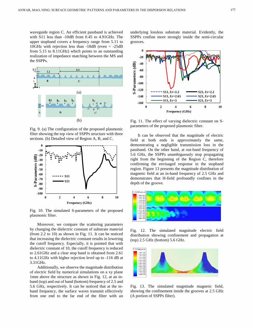
Additionally, we observe the magnitude distribution
of electric field by numerical simulations on a xy plane
1mm above the structure as shown in Fig. 12, at an in-
band (top) and out of band (bottom) frequency of 2.5 and
5.6 GHz, respectively. It can be noticed that at the in-
band frequency, the surface waves transmit effectively
from one end to the far end of the filter with an
underlying lossless substrate material. Evidently, the
SSPPs confine more strongly inside the semi-circular
grooves.
Fig. 11. The effect of varying dielectric constant on S-
parameters of the proposed plasmonic filter.
It can be observed that the magnitude of electric
field at both ends is approximately the same,
demonstrating a negligible transmission loss in the
passband. On the other hand, at out-band frequency of
5.6 GHz, the SSPPs unambiguously stop propagating
right from the beginning of the Region C, therefore
confirming the envisaged response in the stopband
region. Figure 13 presents the magnitude distribution of
magnetic field at an in-band frequency of 2.5 GHz and
demonstrates that H-field profoundly confines in the
depth of the groove.
Fig. 12. The simulated magnitude electric field
distribution showing confinement and propagation at
(top) 2.5 GHz (bottom) 5.6 GHz.
Fig. 13. The simulated magnitude magnetic field,
showing the confinement inside the grooves at 2.5 GHz
(A portion of SSPPs filter).
-100
-90
-80
-70
-60
-50
-40
-30
-20
-10
0
0 2 4 6 8 10
S-P
ara
met
ers
(dB
)
Frequency (GHz)
S11
S21
-160
-140
-120
-100
-80
-60
-40
-20
0
0 2 4 6 8 10
S-P
ara
met
ers
(dB
)
Frequency (GHz)
S11, Ԑr=2.2 S21, Ԑr=2.2
S11, Ԑr=2.65 S21, Ԑr=2.65
S11, Ԑr=3 S21, Ԑr=3
ANWAR, MAO, NING: SURFACE GEOMETRIC PATTERNS AND PARAMETERS IN THE DISPERSION RELATIONS 177
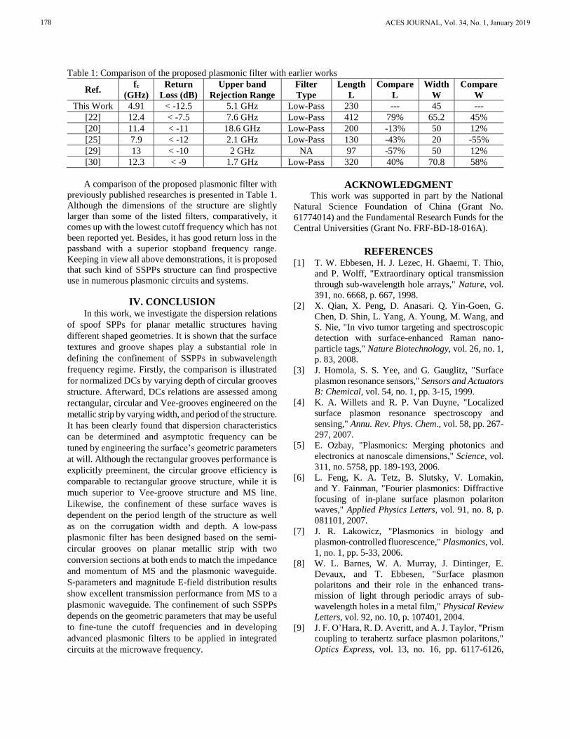
Table 1: Comparison of the proposed plasmonic filter with earlier works
Ref. fc
(GHz)
Return
Loss (dB)
Upper band
Rejection Range
Filter
Type
Length
L
Compare
L
Width
W
Compare
W
This Work 4.91 < -12.5 5.1 GHz Low-Pass 230 --- 45 ---
[22] 12.4 < -7.5 7.6 GHz Low-Pass 412 79% 65.2 45%
[20] 11.4 < -11 18.6 GHz Low-Pass 200 -13% 50 12%
[25] 7.9 < -12 2.1 GHz Low-Pass 130 -43% 20 -55%
[29] 13 < -10 2 GHz NA 97 -57% 50 12%
[30] 12.3 < -9 1.7 GHz Low-Pass 320 40% 70.8 58%
A comparison of the proposed plasmonic filter with
previously published researches is presented in Table 1.
Although the dimensions of the structure are slightly
larger than some of the listed filters, comparatively, it
comes up with the lowest cutoff frequency which has not
been reported yet. Besides, it has good return loss in the
passband with a superior stopband frequency range.
Keeping in view all above demonstrations, it is proposed
that such kind of SSPPs structure can find prospective
use in numerous plasmonic circuits and systems.
IV. CONCLUSION In this work, we investigate the dispersion relations
of spoof SPPs for planar metallic structures having
different shaped geometries. It is shown that the surface
textures and groove shapes play a substantial role in
defining the confinement of SSPPs in subwavelength
frequency regime. Firstly, the comparison is illustrated
for normalized DCs by varying depth of circular grooves
structure. Afterward, DCs relations are assessed among
rectangular, circular and Vee-grooves engineered on the
metallic strip by varying width, and period of the structure.
It has been clearly found that dispersion characteristics
can be determined and asymptotic frequency can be
tuned by engineering the surface’s geometric parameters
at will. Although the rectangular grooves performance is
explicitly preeminent, the circular groove efficiency is
comparable to rectangular groove structure, while it is
much superior to Vee-groove structure and MS line.
Likewise, the confinement of these surface waves is
dependent on the period length of the structure as well
as on the corrugation width and depth. A low-pass
plasmonic filter has been designed based on the semi-
circular grooves on planar metallic strip with two
conversion sections at both ends to match the impedance
and momentum of MS and the plasmonic waveguide.
S-parameters and magnitude E-field distribution results
show excellent transmission performance from MS to a
plasmonic waveguide. The confinement of such SSPPs
depends on the geometric parameters that may be useful
to fine-tune the cutoff frequencies and in developing
advanced plasmonic filters to be applied in integrated
circuits at the microwave frequency.
ACKNOWLEDGMENT This work was supported in part by the National
Natural Science Foundation of China (Grant No.
61774014) and the Fundamental Research Funds for the
Central Universities (Grant No. FRF-BD-18-016A).
REFERENCES [1] T. W. Ebbesen, H. J. Lezec, H. Ghaemi, T. Thio,
and P. Wolff, "Extraordinary optical transmission
through sub-wavelength hole arrays," Nature, vol.
391, no. 6668, p. 667, 1998.
[2] X. Qian, X. Peng, D. Anasari. Q. Yin-Goen, G.
Chen, D. Shin, L. Yang, A. Young, M. Wang, and
S. Nie, "In vivo tumor targeting and spectroscopic
detection with surface-enhanced Raman nano-
particle tags," Nature Biotechnology, vol. 26, no. 1,
p. 83, 2008.
[3] J. Homola, S. S. Yee, and G. Gauglitz, "Surface
plasmon resonance sensors," Sensors and Actuators
B: Chemical, vol. 54, no. 1, pp. 3-15, 1999.
[4] K. A. Willets and R. P. Van Duyne, "Localized
surface plasmon resonance spectroscopy and
sensing," Annu. Rev. Phys. Chem., vol. 58, pp. 267-
297, 2007.
[5] E. Ozbay, "Plasmonics: Merging photonics and
electronics at nanoscale dimensions," Science, vol.
311, no. 5758, pp. 189-193, 2006.
[6] L. Feng, K. A. Tetz, B. Slutsky, V. Lomakin,
and Y. Fainman, "Fourier plasmonics: Diffractive
focusing of in-plane surface plasmon polariton
waves," Applied Physics Letters, vol. 91, no. 8, p.
081101, 2007.
[7] J. R. Lakowicz, "Plasmonics in biology and
plasmon-controlled fluorescence," Plasmonics, vol.
1, no. 1, pp. 5-33, 2006.
[8] W. L. Barnes, W. A. Murray, J. Dintinger, E.
Devaux, and T. Ebbesen, "Surface plasmon
polaritons and their role in the enhanced trans-
mission of light through periodic arrays of sub-
wavelength holes in a metal film," Physical Review
Letters, vol. 92, no. 10, p. 107401, 2004.
[9] J. F. O’Hara, R. D. Averitt, and A. J. Taylor, "Prism
coupling to terahertz surface plasmon polaritons,"
Optics Express, vol. 13, no. 16, pp. 6117-6126,
ACES JOURNAL, Vol. 34, No. 1, January 2019178

2005.
[10] H. Raether, "Surface plasmons on smooth surfaces,"
in Surface Plasmons on Smooth and Rough
Surfaces and on Gratings: Springer, pp. 4-39, 1988.
[11] J. Pendry, L. Martin-Moreno, and F. Garcia-Vidal,
"Mimicking surface plasmons with structured
surfaces," Science, vol. 305, no. 5685, pp. 847-848,
2004.
[12] A. P. Hibbins, B. R. Evans, and J. R. Sambles,
"Experimental verification of designer surface
plasmons," Science, vol. 308, no. 5722, pp. 670-
672, 2005.
[13] L. Martin-Moreno and F. Garcia-Vidal, "Optical
transmission through circular hole arrays in
optically thick metal films," Optics Express, vol.
12, no. 16, pp. 3619-3628, 2004.
[14] F. J. Garcia-Vidal, L. Martin-Moreno, T. Ebbesen,
and L. Kuipers, "Light passing through sub-
wavelength apertures," Reviews of Modern Physics,
vol. 82, no. 1, p. 729, 2010.
[15] X. Shou, A. Agrawal, and A. Nahata, "Role of metal
film thickness on the enhanced transmission
properties of a periodic array of subwavelength
apertures," Optics Express, vol. 13, no. 24, pp.
9834-9840, 2005.
[16] X. Wan and T. J. Cui, "Guiding spoof surface
plasmon polaritons by infinitely thin grooved metal
strip," Aip Advances, vol. 4, no. 4, p. 047137, 2014.
[17] X. Gao, L. Zhou, Z. Liao, H. F. Ma, and T. J. Cui,
"An ultra-wideband surface plasmonic filter in
microwave frequency," Applied Physics Letters,
vol. 104, no. 19, p. 191603, 2014.
[18] T. Søndergaard and S. I. Bozhevolnyi, "Surface-
plasmon polariton resonances in triangular-groove
metal gratings," Physical Review B, vol. 80, no. 19,
p. 195407, 2009.
[19] C. Chen, "A new kind of spoof surface plasmon
polaritons structure with periodic loading of T-
shape grooves," AIP Advances, vol. 6, no. 10, p.
105003, 2016.
[20] R. S. Anwar, Y. Wei, L. Mao, X. Li, and H. Ning,
"Novel spoof surface plasmon polaritons on a
planar metallic strip with periodic semi-elliptical
grooves at microwave frequency," Journal of
Electromagnetic Waves and Applications, pp. 1-13,
2018.
[21] R. S. Anwar, H. Ning, L. Mao, and "Recent
advancements in surface plasmon polaritons-
plasmonics in subwavelength structures at micro-
wave and terahertz regimes," Digital Commun-
ications and Networks, 2017.
[22] H. C. Zhang, Q. Zhang, J. F. Liu, W. Tang, Y.
Fan, and T. J. Cui, "Smaller-loss planar SPP
transmission line than conventional microstrip in
microwave frequencies," Scientific Reports, vol. 6,
2016.
[23] X. Liu, Y. Feng, B. Zhu, J. Zhao, and T. Jiang,
"High-order modes of spoof surface plasmonic
wave transmission on thin metal film structure,"
Optics Express, vol. 21, no. 25, pp. 31155-31165,
2013.
[24] X. Shen, T. J. Cui, D. Martin-Cano, and F.
J. Garcia-Vidal, "Conformal surface plasmons
propagating on ultrathin and flexible films,"
Proceedings of the National Academy of Sciences,
vol. 110, no. 1, pp. 40-45, 2013.
[25] J. Xu, Z. Li, L. Liu. C. Chen, B. Xu, P. Ning,
and C. Gu., "Low-pass plasmonic filter and its
miniaturization based on spoof surface plasmon
polaritons," Optics Communications, vol. 372, pp.
155-159, 2016.
[26] J. Wang, H. Ning, Q. Xiong, and L. Mao, "A
compact narrow-band bandstop filter using spiral-
shaped defected microstrip structure," Radio-
engineering, vol. 23, no. 1, 2014.
[27] H. Ning, J. Wang, Q. Xiong, and L. Mao, "Design
of planar dual and triple narrow-band bandstop
filters with independently controlled stopbands and
improved spurious response," Progress In Electro-
magnetics Research, vol. 131, pp. 259-274, 2012.
[28] H. Ning, J. Wang, Q. Xiong, H. Liu, and L. Mao,
"A compact quad-band bandstop filter using dual-
plane defected structures and open-loop resonators,"
IEICE Electronics Express, vol. 9, no. 21, pp. 1630-
1636, 2012.
[29] S. Zhou, et al., "Spoof surface plasmon polaritons
power Divider with large Isolation," Scientific
Reports, vol. 8, no. 1, p. 5947, 2018.
[30] H. F. Ma, X. Shen, Q. Cheng, W. X. Jiang, and T.
J. Cui, "Broadband and high‐efficiency conversion
from guided waves to spoof surface plasmon
polaritons," Laser & Photonics Reviews, vol. 8, no.
1, pp. 146-151, 2014.
ANWAR, MAO, NING: SURFACE GEOMETRIC PATTERNS AND PARAMETERS IN THE DISPERSION RELATIONS 179
Top Related