


Languages
Pages
Legal


Resolving Furnace and A/C RFI (Radio Frequency Interference) Problems:
Lessons Learned
Roger Hillson / KM4LHZA presentation for the Virginia Wireless Society
https://viennawireless.net/wp/2 OCT 2017– (version 9 – with post‐presentation
corrections & extensions)
1
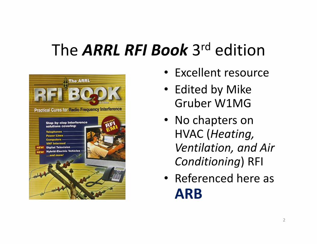
The ARRL RFI Book 3rd edition• Excellent resource• Edited by Mike Gruber W1MG
• No chapters on HVAC (Heating, Ventilation, and Air Conditioning) RFI
• Referenced here as ARB
2

• EMI and RFI are used interchangeably here. – EMI is any frequency of electrical noise– RFI is a specific subset of electrical noise on the radio frequency spectrum.
–• Conducted EMI is electromagnetic energy that is propagated along a conductor(s). In a typical RFIscenario, the conductor(s) act as an antenna to radiate the RF energy. House wiring is a common radiator of conducted emissions. This tends to be more of an RFI issue at frequencies below 30 MHz.
3
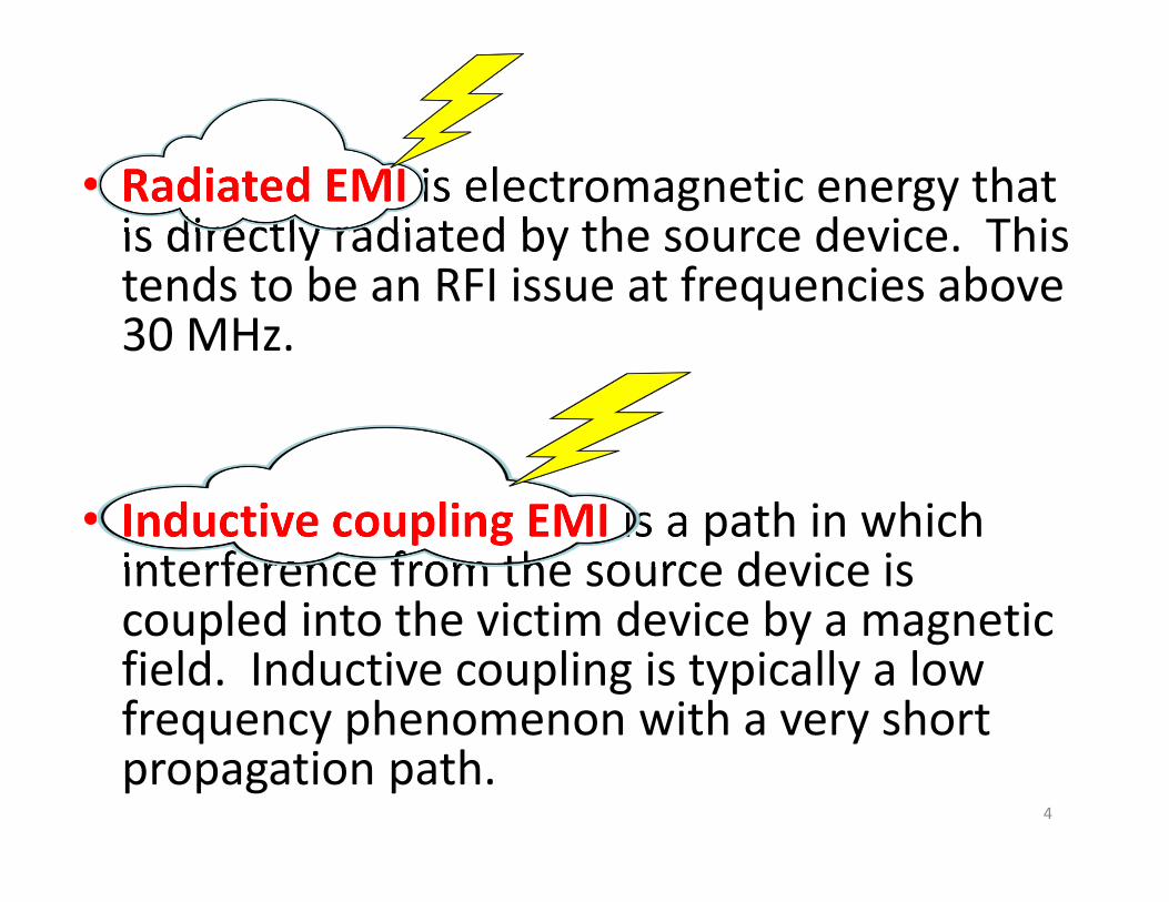
• Radiated EMI is electromagnetic energy that is directly radiated by the source device. This tends to be an RFI issue at frequencies above 30 MHz.
• Inductive coupling EMI is a path in which interference from the source device is coupled into the victim device by a magnetic field. Inductive coupling is typically a low frequency phenomenon with a very short propagation path.
4
The Most Common RFI Mode
• Interference from conducted emissions is usually caused by radiation from wires and cables connected to the RFI source.
• The radiated noise from the power and house wiring is then picked up by the antenna, and enters the radio via the RF connection.
• Conducted RFI via the power connection is a less common source of interference.– Re: Mike Gruber / W1MG / personal communication
5
FINDING LOCAL RFI SOURCES BY ELIMINATION
AC = alternating currentA/C = air conditioning unitCommon Mode Noise: noise that is in phase in 2 or more conductors of an antenna lead or other differential signal source. There is typically a ground return path for the in‐phase noise in both conductors. 6
Because sometimes it’s good to be out of the loop ...

7
Conducted & radiated interference: Conducted: FROM a transmitter TO the AC powerlineRadiated: FROM the transmitter antenna to a TV antennafrom ARB p. 2.5
Common‐mode signal with ground return, as with a long wire antenna.from ARB p. 2.6

1. Turn off EVERYTHING electrical (fluorescent lights, computers, cell phone chargers, television monitor and box, routers, furnace, A/C...)
2. Turn elec. devices back on individually.With furnace on, try ‘fan only’ mode, ‘heating’ mode, and ‘cooling [AC]’ mode.
3. Document the RFI with monitor screen shots if possible .
8

Radiated vs Conducted RFI 1/2• If possible, operate the radio on battery power.–Conducted RFI through the AC power line and/or outboard transceiver power supply may be temporarily eliminated.
–Radiated RFI will still cause RFI.–Of course, both conducted and radiated RFI may be present.
9

Radiated vs Conducted RFI 2/2• As an alternative to using battery power, disconnect the antenna.–Conducted RFI through the AC power line and/or outboard transceiver power supply will – if present ‐ still cause RFI.
–It may be necessary to reset the threshold for the spectrum waterfall display, if the transceiver has one.
–RFI sniffers ... (next slide). 10
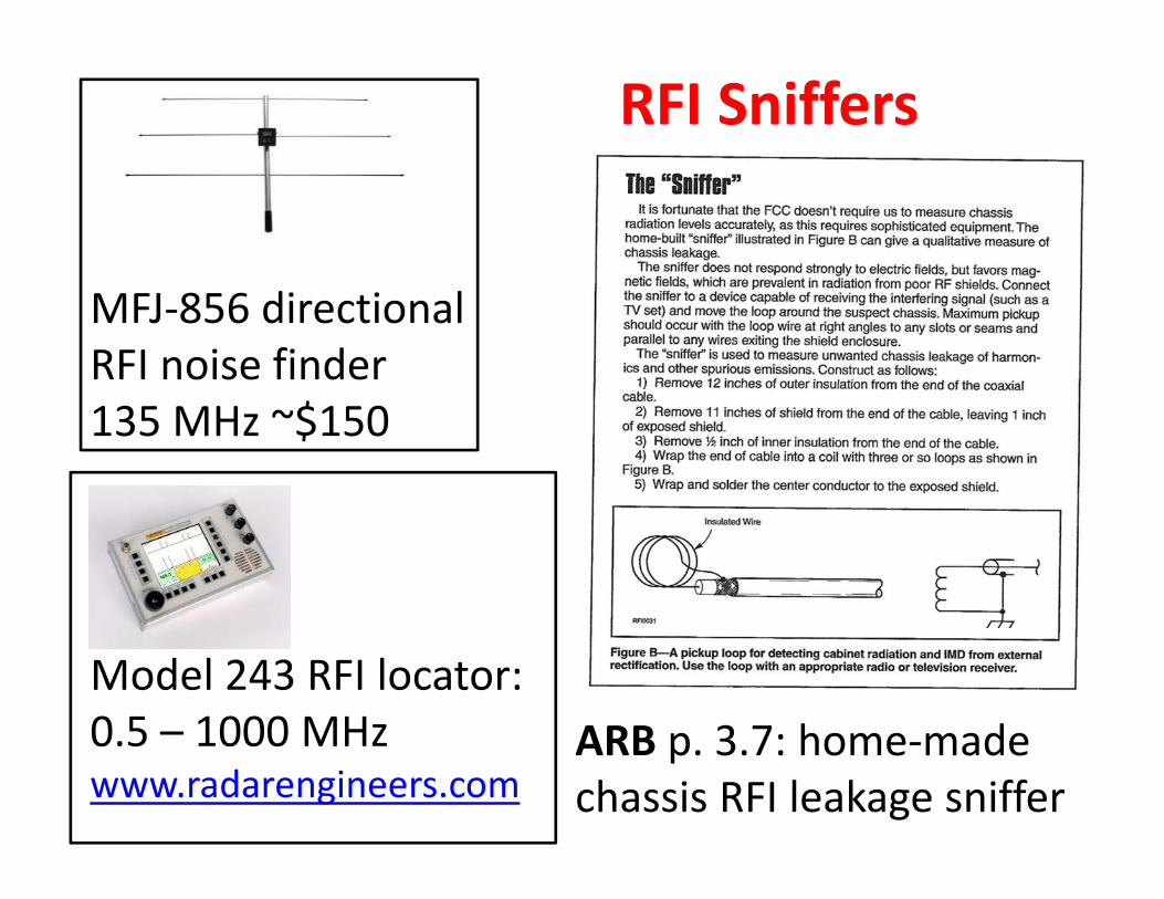
RFI Sniffers
11
MFJ‐856 directional RFI noise finder 135 MHz ~$150
Model 243 RFI locator: 0.5 – 1000 MHzwww.radarengineers.com
ARB p. 3.7: home‐made chassis RFI leakage sniffer

Documenting my RFI problems• ‘Myantennas’ 65 ft endfed EFHX‐4010‐1K wire antenna• ‘Myantennas’ CMS‐130‐3K common mode choke (between the downfeedand the lightening arrestor)• IC‐7300 with built‐in monitor (Screenshots taken with Canon A590Powershot camera)
12

15:17 EST:left –furnace OFF –normal signals, no furnace RFI
15:17 EST:right – Furnace ON; main blower ON (No RFI if main blower fan is off, even though gas pilot is on.) The bands are approximately 18 kHz apart.
RFI interference from furnace blower motor
28 MHz
13

When the A/C (outside unit; 240 v) is turned on, additional interference bands present on top of the ‘picket fence’ bands from the blower, approximately 35 kHz apart. The blower interference is still present.
14

Overview of furnace and air conditioning systems
15

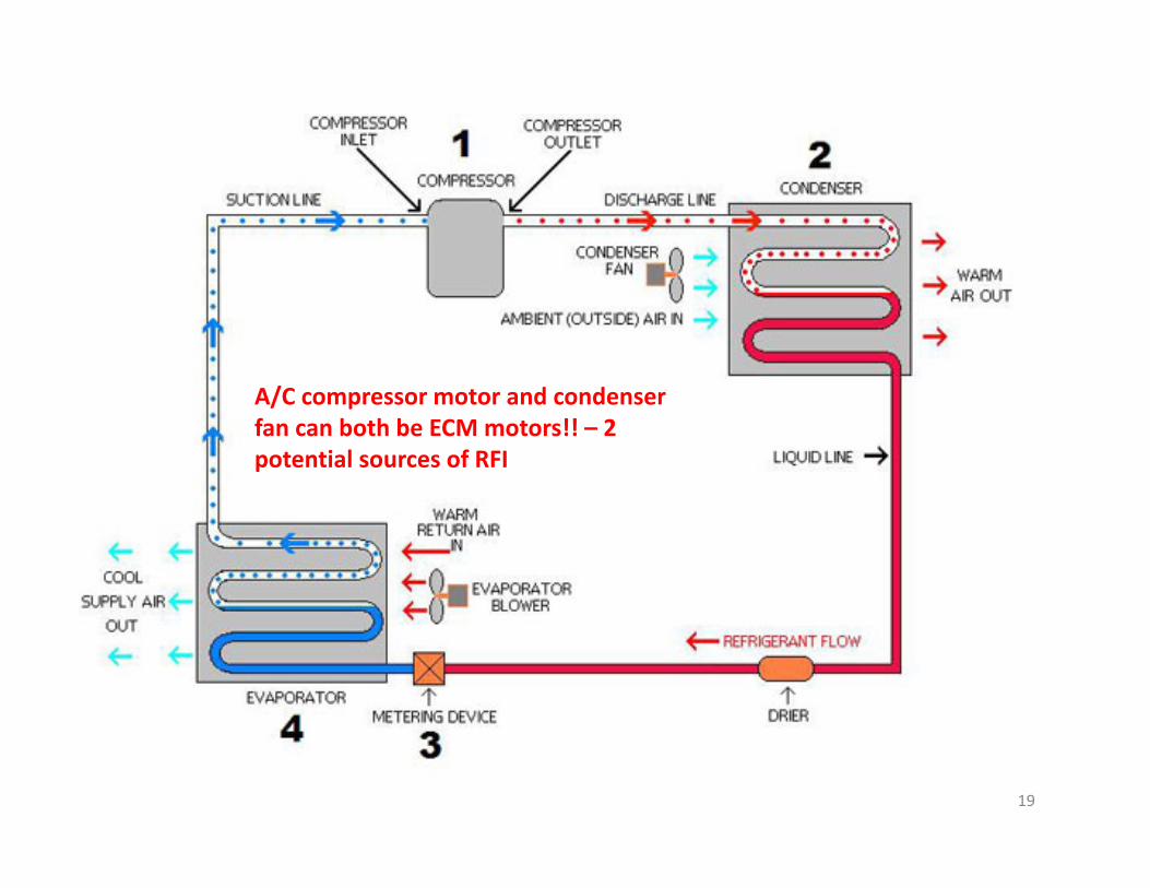
Furnace and A/C components:–Furnace: • induction fan, which draws air from the outside‐ until recently, rarely the source of RFI, but newer systems may use an ECM or induction motor with a variable frequency drive. In either case, there is the possibility of RFI.• blower fan which circulates heated/cooled air.
–A/C units:• a condenser fan motor• a compressor motor. 16

http://www.standardheating.com/hvac‐maintenance/hvac‐diagram/
A/C compressor motor and condenser fan motor can also BOTH be ECM motors!! – 2 potential sources of RFI
In a furnace, both the blower motor and induction motor can be ECM motors. Both are potential sources of RFI.
& motor
17
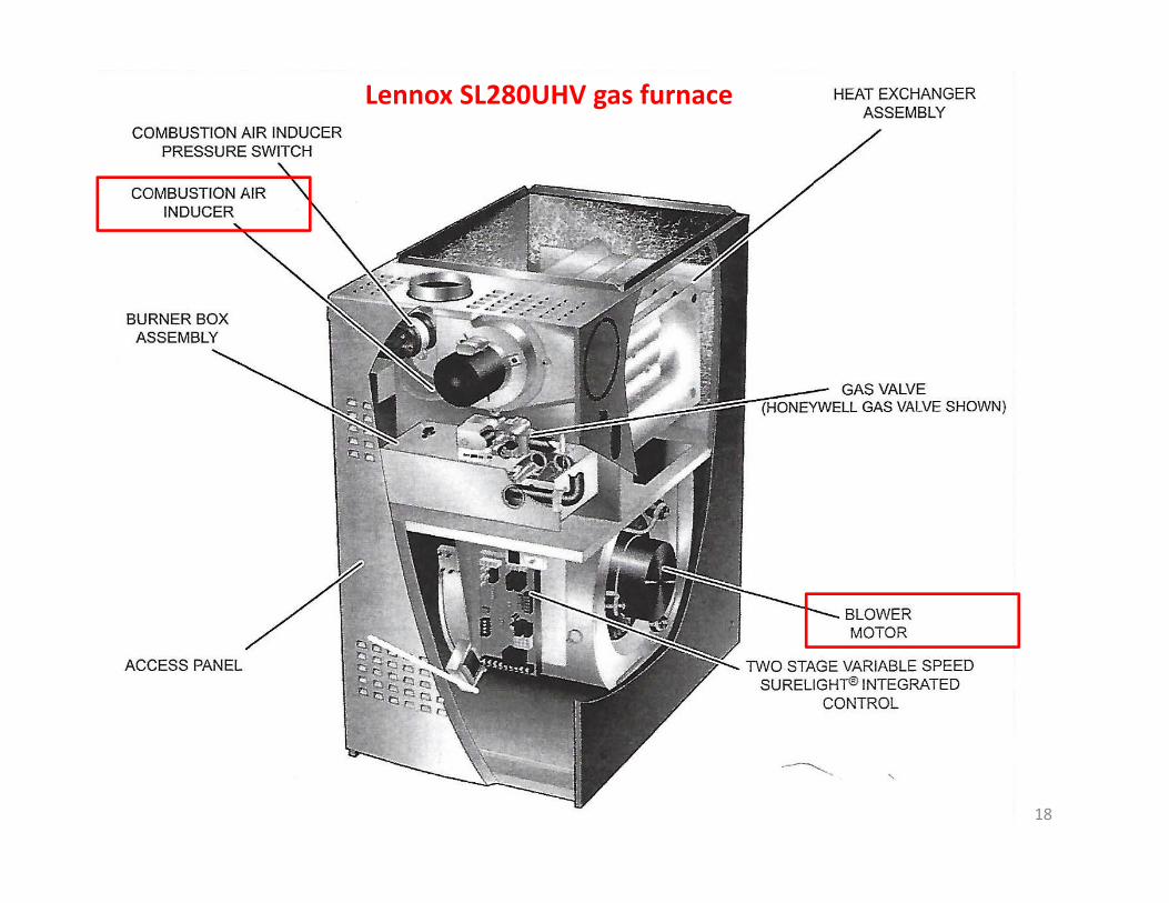
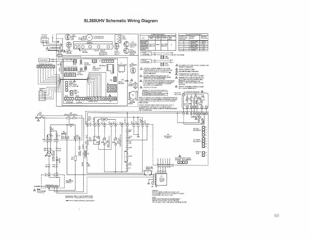
Lennox SL280UHV gas furnace
18
A/C compressor motor and condenser fan can both be ECM motors!! – 2 potential sources of RFI
19

SOURCES OF RFI FROM “HIGH‐END” [I.E. HIGH‐EFFICIENCY] FURNACES AND AIR
CONDITIONING UNITS USING ECM (ELECTRONIC COMMUTATORLESS MOTORS)
Why “going green” with HVAC may contribute to RFI:
Because ECMs (Electronically Commutated Motor) may be used for the furnace blower, A/C compressor, and/or A/C Condenser fan
20

ECM (Electronically Commutated Motor) 3.05‐pin connector to motor: 120 VAC or 240 VAC is continually on.4‐ or 16‐pin connector to motor carries low‐voltage control signals
from ‘The ECM Textbook’
21

Pulse Width ModulationThere are many different ways to control the speed of motors but Pulse Width Modulation (PWM) is common/simple.
from:http://www.electronics‐tutorials.ws/blog/pulse‐width‐modulation.html
22

(1) http://www.samlexamerica.com/support/faqs/faq18.aspx(2) https://www.engineersgarage.com/articles/smps‐switched‐mode‐power‐supply
Sources of switching power supply noise (ref 1):(1) Switching frequency harmonics [15‐50 kHz (2)](2)Broadband noise created by under‐damped
oscillations in the switching circuit.(3) The AC input rectifier / capacitor “are notorious”
for generating power supply harmonics because of the non‐linear input waveform.
23
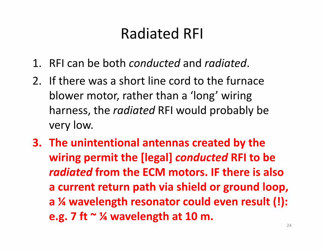
Radiated RFI
1. RFI can be both conducted and radiated.2. If there was a short line cord to the furnace
blower motor, rather than a ‘long’ wiring harness, the radiated RFI would probably be very low.
3. The unintentional antennas created by the wiring permit the [legal] conducted RFI to be radiated from the ECM motors. IF there is also a current return path via shield or ground loop, a ¼ wavelength resonator could even result (!): e.g. 7 ft ~ ¼ wavelength at 10 m.
24
FCC Regulations
Not as stringent as you think?
25

FCC Regulations Regulating RFICFR (Code of Federal Regulations) (2009) Title 47:
‐ TelecommunicationsVolume (Chapter) 1
‐ Federal Communications Commission regulationsPart 15:
‐ RADIO FREQUENCY DEVICESParts 15.105 – 15.109 [Unintentional Radiators]
‐ RFI standards, etc.
The entire 120 page document is available at :http://www.curtisind.com/files/pdf/CFR‐2009‐title47‐vol1‐part15.pdf
26

(Above) Permissible RF voltage conducted back into the AC power line, as measured using a 50 H/50 ohms Line Impedance Stabilization Network (LISN), which should drive the line impedance to 50 ohms. (H=microHenries)
27
316 V
dBμV = 20log₁₀(VOUT/1μV) [not dimensionless]
Permissible Levels of Conducted Radio Frequency Voltage (15.107)
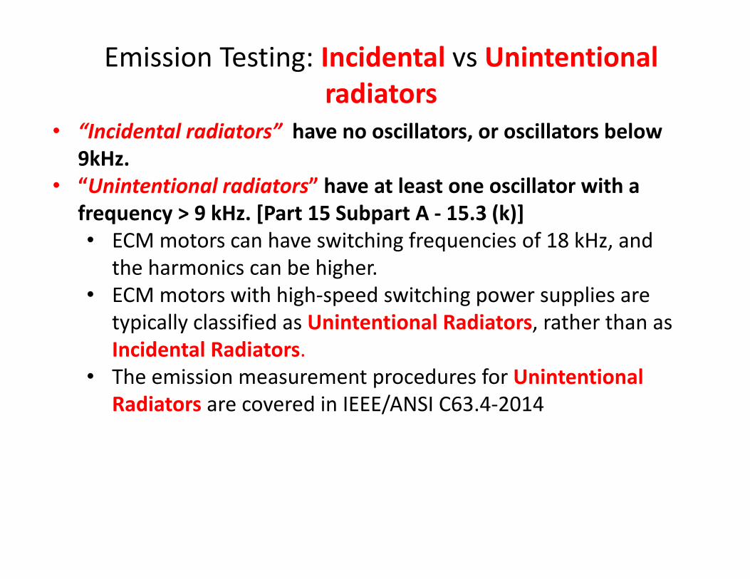
• “Incidental radiators” have no oscillators, or oscillators below 9kHz.
• “Unintentional radiators” have at least one oscillator with a frequency > 9 kHz. [Part 15 Subpart A ‐ 15.3 (k)]• ECM motors can have switching frequencies of 18 kHz, and
the harmonics can be higher.• ECM motors with high‐speed switching power supplies are
typically classified as Unintentional Radiators, rather than as Incidental Radiators.
• The emission measurement procedures for Unintentional Radiators are covered in IEEE/ANSI C63.4‐2014
Emission Testing: Incidental vs Unintentional radiators

29
• ECM motors can have switching frequencies of 18 kHz, and the harmonics can be higher.
• ECM motors with high‐speed switching power supplies are typically classified as Unintentional Radiators, rather than as Incidental Radiators.• The emission measurement procedures for Unintentional
Radiators are covered in IEEE/ANSI C63.4‐2014
Emission Test Requirements for Unintentional Radiators

[Above] The emitted field strength from unintentional radiators shall not exceed the above at a distance of 3 meters. [Continued on next slide.]
There is no requirement to test field strength below 30 MHz.
For Class B(residential ) digital devices
30
Emission Testing: Unintentional radiators

Eliminating the RFI
31

Safety first ...• For the air conditioning unit, the A/C disconnect switch or breaker should be set to ‘off’ (right) prior to attempting any repairs Turning off the furnace does not disconnect the power to the A/C unit.
Lockout ‘ON.’ Remove, invert, and reinsert the disconnect switch (breaker) to lockout ‘OFF’.
Lockout ‘OFF’
32

Steps in troubleshooting HVAC I1. Check your HVAC
warranty – (3 years into 10 year Lennox warranty)
2. If system under warranty, work through your dealer.
3. If possible, differentiate between conducted EMIinto power line and radiated EMI
4. Test system in different modes (may require dealer support):– furnace blower on; no heating or cooling
– A/C: compressor only; condenser fan OFF. (May be necessary to have furnace blower fan on.)
– A/C: condenser fan only; compressor OFF
33

Steps in troubleshooting II
5. Identify specific components causing RFI – in my case:– furnace blower ECM motor, induction motor in my system is not ECM.
– A/C compressor ECM motor
7. Try to identify manufacturer, model, and S/N for above components. Vendor [e.g. Lennox] part number may be insufficient.
8. Document with screen shots, if possible.
34

Steps in troubleshooting III– Compressor ECM motor.
LG has large inductive reactance filter.
– There is also 3‐phase drive to the motor windings, and the return current must be properly handled to avoid radiated EMI.
– Lennox field service diagnosed and fixed LG compressor motor issue due to radiated EMI.
8. Fix & test – hopefully with assistance from HVAC dealer and manufacturer. In my case, ACE HVAC covered all costs of repair.– Furnace lower fan ECM
motor. – Regal Beloit [pronounced
BEL’‐oit ‐ rhymes with DE’‐troit] provided custom RFI filter for furnace blower motor – Genteq ECM 3.0 model
35
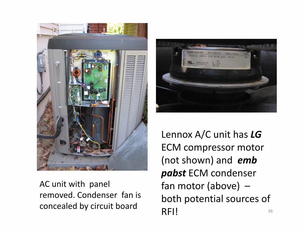
AC unit with panel removed. Condenser fan is concealed by circuit board
Lennox A/C unit has LGECM compressor motor (not shown) and embpabst ECM condenser fan motor (above) –both potential sources of RFI! 36

S/N G 14V223139 ... Genteq (Regal Beloit) blower motor
An endoscope with a reversing mirror attachment was used to read S/N and manufacturer of furnace blower motor.
Furnace blower motor
37

Furnace blower motor filter
Provided by Regal Beloit to eliminate radiated RFI via potential ground
loop
38

The Regal Beloit blower motor RFIfilter
• After I confirmed the manufacturer (Genteq,manufactured by Regal Beloit) and model S/N, Regal Beloit provided a custom RFI filter for the ECM 3.0 blower motor.
• The filter plugs directly into the control port of the ECM motor, and the wire harness plugs into the filter.
• Installed by ACE Heating and Cooling.
39

Regal RFI filter:At the J45 connector of the wire harness to the B3 indoor blower motor.1. capacitor from 5 to 32. capacitor from 4 to 33. ferrite chokes on control wires 5 and
4 – between L13 and the blower motor. (L13 may not be present in my system.)
5: L1HOT
3: GND
4: L2/NHOT
3 binocular (clamp‐on) ferrite chokes (blue square)
capacitor (.01 ufd, 250 v)
L13
40

The ECM 3.0 filter – images provided courtesy of Regal Beloit.41

The shrink‐wrapped Regal Beloit RFI filter plugged into the ECM 3.0 Genteq blower motor.
Plug for control wire harness to blower motor
Regal Beloit RFI filter plugs into ECM 3.0 motor
42

A/C unit
Fix ungrounded wires in thermostat harness
43

LG compressor motor
• Company asserts no significant conducted EMI because of significant inductive reactance EMI filter on control board.
• Radiated RFI could not be ruled out as a function of the installation
44
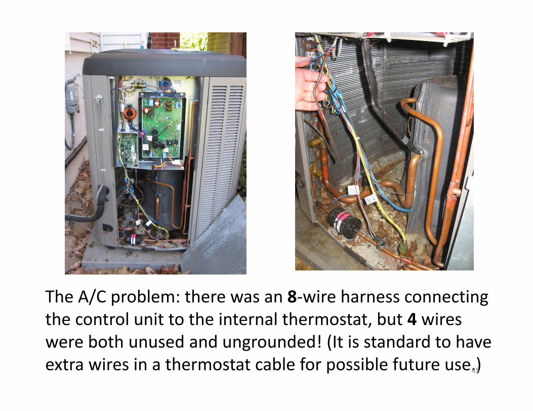
The A/C problem: there was an 8‐wire harness connecting the control unit to the internal thermostat, but 4 wires were both unused and ungrounded! (It is standard to have extra wires in a thermostat cable for possible future use.)45

Lennox’s solution: bare (A) and ground the 4 unused wires, and add external ferrite core chokes as an added precaution (C and D). The 4 unused wires no longer serve as inductive radiators propagating RFI back into the house.
A CB
46
Manufacturer‐specific motor and wiring harness identification
• Identifying the motor and wiring harness can facilitate RFI diagnosis and resolution.
• For example, each Genteq/Regal Beloitmotor, typically have a (1) family designation and a (2) manufacturer model number:– The motor family designators e.g. ECM 3.0, Endura, EON ... identify the class of indoor blower motor.
• The model number on the Regal nameplate will always begin with 5SME93xxx.
• This number identifies the distinctive wiring harnesses used in external units. e.g.– In a ‘remote’ motor, the
switching control unit is physically separated from the motor body proper.
– If so, a torroidal ferrite choke may be required to suppress unintentional radiation from the cable connecting the control unit to the motor.
47

Problem solved ...
With furnace blower and A/C on full, no more interference on any bands
48

SUCCESS! With the furnace blower and A/C running at full power, 10m had no RFI, and 20m had normal activity and also no RFI. 49

A few internet memes ....
50

“(1) Since I’m getting interference, the furnace or A/C is not FCC‐compliant”
• Usually not true ...
• A small level of conducted AC EMI is permitted by regulation – see preceding slides.
• Manufacturers are not required to test for radiated EMI below 30 mHz.
• Radiated EMI can occur because of improper grounding, inadvertent ground loops, or improper wiring installation.
51

Example courtesy of Regal Beloit. A commercial EMI filter will noteliminate RFI here, because it will shunt RF from L1 and L2 to ground, but the return conduction (in red) through metal case is being radiated. Instead, we must shunt RF to ground right at the adapter plate.
52
“(2) Installing an EMI line filter will eliminate your problems”
• Depends on the cause ...
• An EMI line filter may not have any effect on radiatedRFI, but can help with conducted common mode RFI from power lines, etc.
• I have a CMC (common mode choke) inline with my antenna, and a Tripp‐Lite surge protector with a cascaded RFI filter bank.
• No FCC requirement to test for radiated EMI below 30 mHz.
• Radiated EMI can occur because of improper grounding, inadvertent ground loops, or improper wiring installation (as in my case).
53

“(3) Shielding the ECM control cables in your furnace will eliminate RFI”
• This DIY could help, but alternative solutions may exist
• See: RFI Mitigation in Rheem RGFG High Efficiency Furnace (AC2EV) for a discussion of successful DIY cable shielding
• http://www.eham.net/articles/32146
• In my system, a custom Regal Beloit filter for the furnace blower motor was used to correct for radiated EMI.
• Ungrounded/unused wires in the A/C wiring harness should be identified and grounded.
54
“(4) If the RFI isn’t fixed, I’ll file an FCC complaint” 1/2
• Always a legal option – but:• (1) RFI may be due to local installation issues, rather than component malfeasance.
• (2) “Many complaints are simply acknowledged, however, and the complainant is told that it will be used for statistical analysis.” re:– http://www.arrl.org/news/redesigned‐fcc‐website‐makes‐it‐easy‐for‐hams‐to‐file‐interference‐complaints
• (3) Informal complaint can be filed for free.– Fee for formal complaint is $225.
• (4) The FCC may simply refer you elsewhere (next slide).55

“(4) If the RFI isn’t fixed, I will file an FCC complaint” 2/2
• See: “The Noise Frontier [NY2RF]” QSTNovember 2016:
• After a post FCC‐consultation by the local authorities, ham radio operators were asked for assistance, and helped the Evanston Illinois police in locating “an errant neon‐light power supply” causing wide‐spread RFI. • The FCC original referred the Evanston police to the automobile manufacturers (!), since wireless key fobs in the area had stopped working.
56

AcknowledgementsACE Air Conditioning and Heating Services (northern VA)
• 14088‐H Sullyfield Circle, Chantilly, VA 20151
• Honored 10‐year warranty on Lennox system 3 years after installation
• Multiple no cost service calls in response to RFIissues
• ‘Fine business’
Services provided through ACE
• Lennox field engineering services– 2 site visits to my home (no
cost)• Regal Beloit, Fort Wayne,
Indiana– email analysis and support– ECM 3.0 filter provided at no
cost by mail – Note ‐ ‘Beloit’ is pronounced
BEL’‐oit] – rhymes with ‘Detroit’ ‐ and not as Bel‐WAH’ ‐ as in my audio presentation. – r.h.
57

APPENDIX
58

59
dBμV or dBuV (decibel microvolt, amplitude ratio) — absolute voltage in decibels relative to one microvolt, used to measure the signal strength in RF and audio cables. That is dBμV = 20log₁₀(VOUT/1μV) where VOUT in μV. This shows that dBμV is independent of impedance. Since it is the ratio of two voltages, they can be measured as peak‐to‐peak or RMS and with the same units. Reference voltage 1 μV.
60

§ 15.105 Information to the user.
(b) For a Class B digital device or peripheral, the instructions furnished the user shall include the following or similar statement, placed in a prominent location in the text of the manual:
NOTE : This equipment has been tested and found to comply with the limits for a Class B digital device, pursuant to part 15 of the FCC Rules. These limits are designed to provide reasonable protection against harmful interference in a residential installation. This equipment generates, uses and can radiate radio frequency energy and, if not installed and used in accordance with the instructions, may cause harmful interference to radio communications. However, there is no guarantee that interference will not occur in a particular installation. If this equipment does cause harmful interference to radio or television reception, which can be determined by turning the equipment off and on, the user is encouraged to try to correct the interference by one or more of the following measures: —Reorient or relocate the receiving antenna. —Increase the separation between the equipment and receiver. —Connect the equipment into an outlet on a circuit different from that to which the re‐ceiver is connected. —Consult the dealer or an experienced radio/ TV technician for help§.
61

Switching Power Supplies
• Switching power supplies are light and efficient, but the switching frequencies may be as high as 1 MHz.
• Manufacturer’s acknowledge this can create RFI problems ... (next slide)
62
• From the Samlex website:http://www.samlexamerica.com/support/faqs/faq18.aspx
• 1. Why are Switched Mode Power Supplies (SMPS) associated with radio interference?
• Switched mode power supplies (SMPS) employ high frequency (HF) switching and thus, are a source of radio interference, a recipient of radio interference and a conduit of radio interference. (Older linear type transformer based power supplies do not employ HF switching voltages).
63

2. What are the typical sources of radio interference in a SMPS?The primary emission sources originate in the switching devices due to their fast switching current transitions: (1) harmonics of the switching frequency and (2) broadband noise created by under‐damped oscillations in the switching circuit. The secondary source is from the bridge rectifier, both rectifier noise and diode recovery. (3) The AC input rectifier / capacitor in the front end of the switching power supplies (excepting those with power factor correction) are notorious for generating power supply harmonics due to the non linear input current waveform. (4) The noise is both conducted and radiated through the input power cord and the DC output wiring to the radio. 64
Top Related