

Languages
Pages
Legal


Bob Rathbone |Raspberry PI Rotary Encoder / 1
Raspberry PI Rotary Encoders
Tutorial
Bob Rathbone Computer Consultancy
www.bobrathbone.com
1st of February 2014

Bob Rathbone |Raspberry PI Rotary Encoder / 2
Contents Introduction ............................................................................................................................................ 3
Raspberry PI computer ....................................................................................................................... 3
Rotary encoder ....................................................................................................................................... 4
The Rotary Class ...................................................................................................................................... 6
Other rotary class calls ........................................................................................................................ 7
GPIO Hardware Notes ............................................................................................................................. 8
Appendix A The rotary encoder class ..................................................................................................... 9
A.1 The rotary_class.py file ................................................................................................................. 9
A.2 The test_rotary_class.py file ....................................................................................................... 11
A.3 Example using two switches ....................................................................................................... 12
Appendix B Licences .............................................................................................................................. 13
Acknowledgements ............................................................................................................................... 13
Glossary ................................................................................................................................................. 14
Tables Table 1 Rotary encoder sequence (Clockwise) ....................................................................................... 5
Table 2 Event interpretation using the delta between events ............................................................... 5
Table 3 Wiring list for Rotary Encoders used in the PI internet radio .................................................... 6
Figures Figure 1 Raspberry PI Computer ............................................................................................................. 3
Figure 2 Rotary encoder wiring ............................................................................................................... 4
Figure 3 Typical incremental rotary encoder .......................................................................................... 4
Figure 4 Quadrature output table ........................................................................................................... 4
Figure 5 Raspberry PI internet radio with Rotary Encoders ................................................................... 6
Bob Rathbone |Raspberry PI Rotary Encoder Introduction 3
Introduction This tutorial has been designed to help students and constructors to understand how to use Rotary
Encoders and to use them in their own Raspberry PI projects. The principle hardware required to
build a project using Rotary Encoders consists of the following components:
A Raspberry PI computer
One or more rotary encoders with or without push button
The rotary_class.py code and associated test programs.
Raspberry PI computer
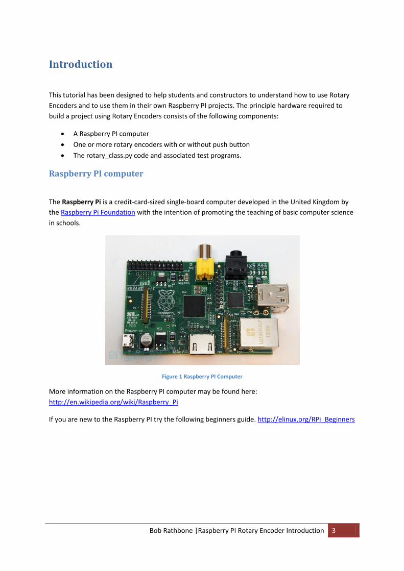
The Raspberry Pi is a credit-card-sized single-board computer developed in the United Kingdom by
the Raspberry Pi Foundation with the intention of promoting the teaching of basic computer science
in schools.
Figure 1 Raspberry PI Computer
More information on the Raspberry PI computer may be found here:
http://en.wikipedia.org/wiki/Raspberry_Pi
If you are new to the Raspberry PI try the following beginners guide. http://elinux.org/RPi_Beginners
Bob Rathbone |Raspberry PI Rotary Encoder Rotary encoder 4
Rotary encoder A good place to start is by taking a look at the following Wikipedia article: http://en.wikipedia.org/wiki/Rotary_encoder There are several types of rotary encoder and encoding used. This tutorial is using the so called
“Incremental Rotary Encoder”. An incremental rotary encoder provides cyclical outputs (only) when
the encoder is rotated.
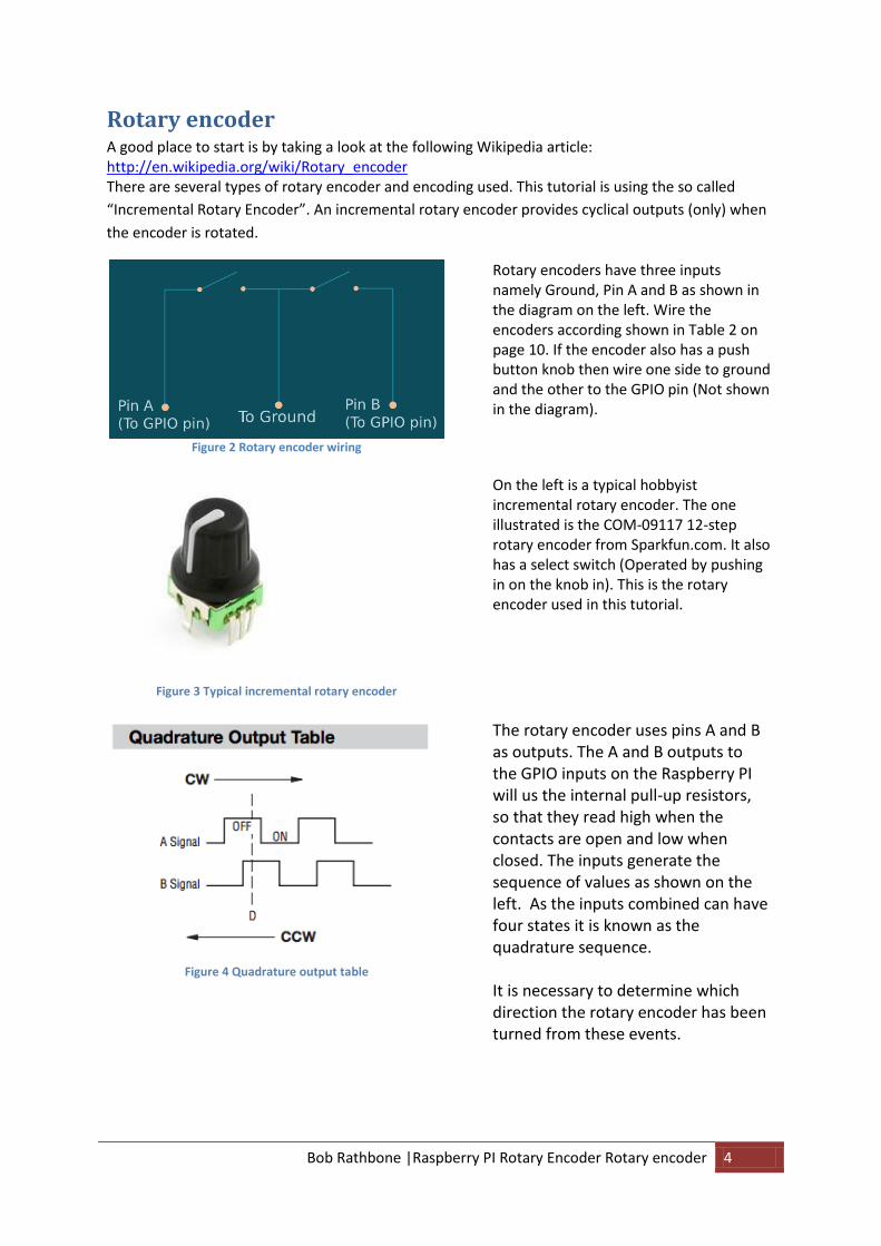
Figure 2 Rotary encoder wiring
Rotary encoders have three inputs namely Ground, Pin A and B as shown in the diagram on the left. Wire the encoders according shown in Table 2 on page 10. If the encoder also has a push button knob then wire one side to ground and the other to the GPIO pin (Not shown in the diagram).
Figure 3 Typical incremental rotary encoder
On the left is a typical hobbyist incremental rotary encoder. The one illustrated is the COM-09117 12-step rotary encoder from Sparkfun.com. It also has a select switch (Operated by pushing in on the knob in). This is the rotary encoder used in this tutorial.
Figure 4 Quadrature output table
The rotary encoder uses pins A and B as outputs. The A and B outputs to the GPIO inputs on the Raspberry PI will us the internal pull-up resistors, so that they read high when the contacts are open and low when closed. The inputs generate the sequence of values as shown on the left. As the inputs combined can have four states it is known as the quadrature sequence. It is necessary to determine which direction the rotary encoder has been turned from these events.

Bob Rathbone |Raspberry PI Rotary Encoder Rotary encoder 5
Table 1 Rotary encoder sequence (Clockwise)
Sequence A B A^B (C) Value
0 0 0 0 0
1 1 0 1 5
2 1 1 0 6
3 0 1 1 3
The trick is to use the bitwise XOR value A^B to transform the input bits into an ordinal sequence number. There is no reason behind the XOR operation other than it to provide the bit sequence. For anti-clocwise the sequence is reversed.
The next task is to determine what direction the rotary encoder has been turned. This is first done by
determining the delta (change) between the the previous state (A + B + (A^)) and the new state. The
following code achieves this:
delta = (new_state - last_state) % 4
The %4 means give the remainder of a divide by 4 operation. The above code produces a value between 0 and 3 as shown in the following table: Table 2 Event interpretation using the delta between events
Delta Meaning
0 No change
1 On step clockwise
2 Two steps clockwise or counter-clockwise
3 On step counter-clockwise
The whole sequence of code (Python) is shown below:
# Get pin A state
if GPIO.input(pinA):
rotary_a = 1
else:
rotary_a = 0
# Get pin B state
if GPIO.input(pinB):
self.rotary_b = 1
else:
self.rotary_b = 0
# Create bit sequence
rotary_c = rotary_a ^ rotary_b
# Get the new rotary encoder state
new_state = rotary_a * 4 + rotary_b * 2 + rotary_c * 1
# Get the delta (difference) between the previous state and the new state
delta = (new_state - last_state) % 4
# Store the state for next time around
last_state = new_state
Why is rotary_a and rotary_b multiplied by 4 and 2 respectively? This is done to produce the value
shown in the last column of Table 1 on page 5. The value of rotary_c will always be 0 or 1.

Bob Rathbone |Raspberry PI Rotary Encoder The Rotary Class 6
The Rotary Class This tutorial uses the rotary_class.py Python class as shown in Appendix A The rotary encoder class.
A class is like a blue print for an object, in this case a rotary encoder. Why use a class? There are a lot
of reasons but lets take a practical example. I wished to use rotary encoders in a project for building
and Internet Radio using the Raspberry PI. For details of this project See:
http://www.bobrathbone.com/raspberrypi_radio.htm
Figure 5 Raspberry PI internet radio with Rotary Encoders
In this project I wish to use one rotary encoder for the volume control and mute functions and the
other for the tuner and menu functions. The following table shows how the rotary encoders are
wired. Of course other GPIO inputs may be used instead in your own project.
Table 3 Wiring list for Rotary Encoders used in the PI internet radio
GPIO Pin Description Function Rotary Encoder 1 (Tuner)
Rotary Encoder 2 (Volume)
6 GND Zero volts Common Common
7 GPIO 4 Mute volume Knob Switch
8 GPIO 14 Volume down Output A
9 Reserved
10 GPIO 15 Volume up Output B
11 GPIO 17 Channel Up Output B
12 GPIO 18 Channel Down Output A
22 GPIO 25 Menu Switch Knob Switch
To use the rotary class it must first be imported into the program that wishes to use it.
from rotary_class import RotaryEncoder

Bob Rathbone |Raspberry PI Rotary Encoder The Rotary Class 7
The general call for the rotary_class is:
knob = RotaryEncoder(PIN_A, PIN_B, BUTTON, event_handler)
Where PIN_A is the rotary encoder A output, PIN_B is the rotary encoder B output, BUTTON is the push button and event_handler is the routine (callback) which will handle the events. The new switch object is called knob. So to define a volume control this would become:
VOLUME_UP = 15 # GPIO pin 10
VOLUME_DOWN = 14 # GPIO pin 8
MUTE_SWITCH = 4 # GPIO pin 7
volumeknob = RotaryEncoder(VOLUME_UP,VOLUME_DOWN,MUTE_SWITCH,volume_event)
We also need to define a routine called volume_event to handle the rotary encoder and push button events. Events are defined in the rotary_class.py file.
CLOCKWISE=1
ANTICLOCKWISE=2
BUTTONDOWN=3
BUTTONUP=4
The event handler looks something like below:
# Call back routine for the volume control knob
def volume_event(event):
global volumeknob
if event == RotaryEncoder.CLOCKWISE:
... Code to handle volume increase
elif event == RotaryEncoder.ANTICLOCKWISE:
... Code to handle volume decrease
elif event == RotaryEncoder.BUTTONDOWN:
... Code to handle mute function
return
In the same way we can define the tuner knob using a separate Rotary_Class definitiion
CHANNEL_UP = 18 # GPIO pin 12
CHANNEL_DOWN = 17 # GPIO pin 11
MENU_SWITCH = 25 # GPIO pin 25
tunerknob = RotaryEncoder(CHANNEL_UP,CHANNEL_DOWN,MENU_SWITCH,tuner_event)
Note that a different routine tuner_event is defined for the tuner event. Now it can be seen that a
single class can be used to define more than one object. In this case the volume_knob and
tuner_knob objects.
Other rotary class calls The state of the rotary encoder push switch can be read with the getSwitchState function.
MutePressed = tunerknob.getSwitchState(MENU_SWITCH)
Bob Rathbone |Raspberry PI Rotary Encoder GPIO Hardware Notes 8
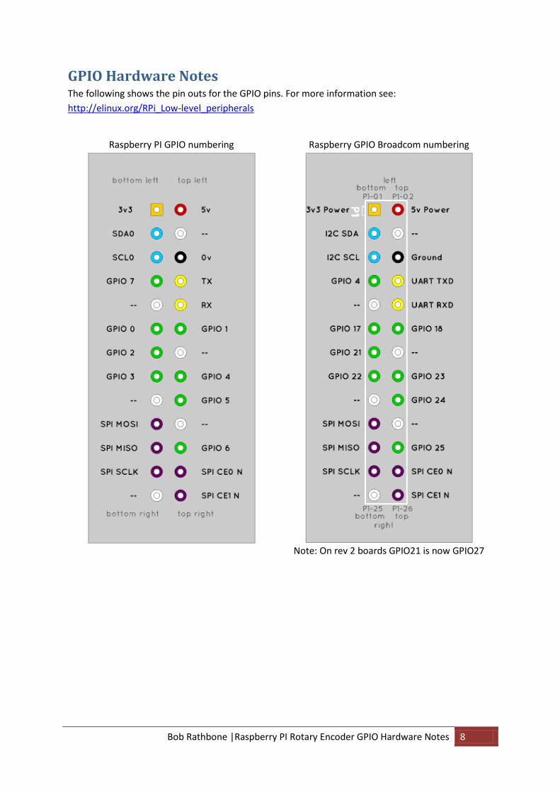
GPIO Hardware Notes The following shows the pin outs for the GPIO pins. For more information see:
http://elinux.org/RPi_Low-level_peripherals
Raspberry PI GPIO numbering Raspberry GPIO Broadcom numbering
Note: On rev 2 boards GPIO21 is now GPIO27
Bob Rathbone |Raspberry PI Rotary Encoder Appendix A The rotary encoder class 9
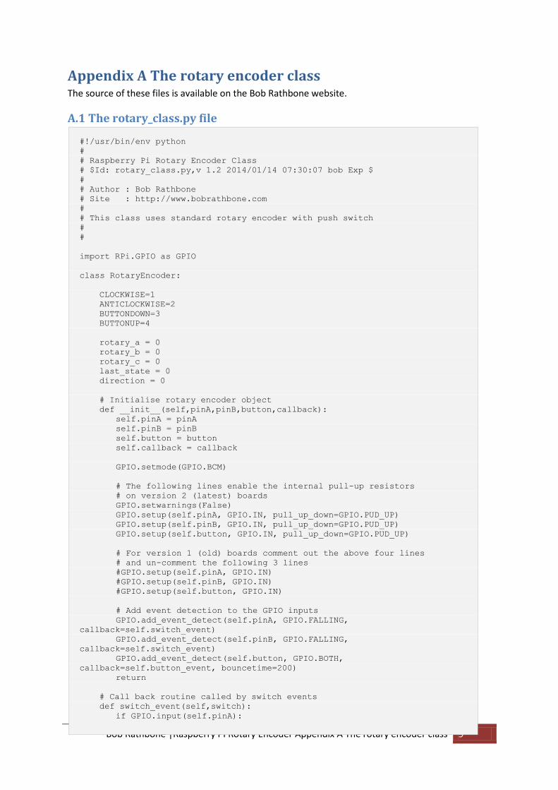
Appendix A The rotary encoder class The source of these files is available on the Bob Rathbone website.
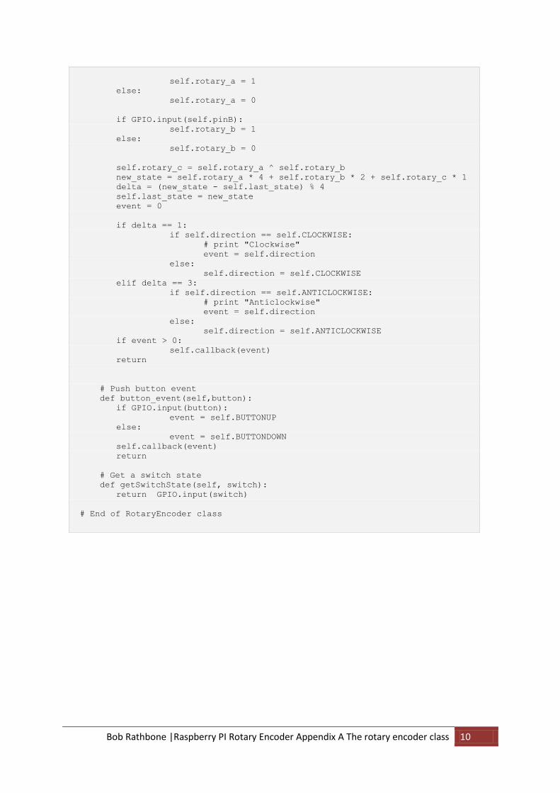
A.1 The rotary_class.py file
#!/usr/bin/env python
#
# Raspberry Pi Rotary Encoder Class
# $Id: rotary_class.py,v 1.2 2014/01/14 07:30:07 bob Exp $
#
# Author : Bob Rathbone
# Site : http://www.bobrathbone.com
#
# This class uses standard rotary encoder with push switch
#
#
import RPi.GPIO as GPIO
class RotaryEncoder:
CLOCKWISE=1
ANTICLOCKWISE=2
BUTTONDOWN=3
BUTTONUP=4
rotary_a = 0
rotary_b = 0
rotary_c = 0
last_state = 0
direction = 0
# Initialise rotary encoder object
def __init__(self,pinA,pinB,button,callback):
self.pinA = pinA
self.pinB = pinB
self.button = button
self.callback = callback
GPIO.setmode(GPIO.BCM)
# The following lines enable the internal pull-up resistors
# on version 2 (latest) boards
GPIO.setwarnings(False)
GPIO.setup(self.pinA, GPIO.IN, pull_up_down=GPIO.PUD_UP)
GPIO.setup(self.pinB, GPIO.IN, pull_up_down=GPIO.PUD_UP)
GPIO.setup(self.button, GPIO.IN, pull_up_down=GPIO.PUD_UP)
# For version 1 (old) boards comment out the above four lines
# and un-comment the following 3 lines
#GPIO.setup(self.pinA, GPIO.IN)
#GPIO.setup(self.pinB, GPIO.IN)
#GPIO.setup(self.button, GPIO.IN)
# Add event detection to the GPIO inputs
GPIO.add_event_detect(self.pinA, GPIO.FALLING,
callback=self.switch_event)
GPIO.add_event_detect(self.pinB, GPIO.FALLING,
callback=self.switch_event)
GPIO.add_event_detect(self.button, GPIO.BOTH,
callback=self.button_event, bouncetime=200)
return
# Call back routine called by switch events
def switch_event(self,switch):
if GPIO.input(self.pinA):
Bob Rathbone |Raspberry PI Rotary Encoder Appendix A The rotary encoder class 10
self.rotary_a = 1
else:
self.rotary_a = 0
if GPIO.input(self.pinB):
self.rotary_b = 1
else:
self.rotary_b = 0
self.rotary_c = self.rotary_a ^ self.rotary_b
new_state = self.rotary_a * 4 + self.rotary_b * 2 + self.rotary_c * 1
delta = (new_state - self.last_state) % 4
self.last_state = new_state
event = 0
if delta == 1:
if self.direction == self.CLOCKWISE:
# print "Clockwise"
event = self.direction
else:
self.direction = self.CLOCKWISE
elif delta == 3:
if self.direction == self.ANTICLOCKWISE:
# print "Anticlockwise"
event = self.direction
else:
self.direction = self.ANTICLOCKWISE
if event > 0:
self.callback(event)
return
# Push button event
def button_event(self,button):
if GPIO.input(button):
event = self.BUTTONUP
else:
event = self.BUTTONDOWN
self.callback(event)
return
# Get a switch state
def getSwitchState(self, switch):
return GPIO.input(switch)
# End of RotaryEncoder class

Bob Rathbone |Raspberry PI Rotary Encoder Appendix A The rotary encoder class 11
A.2 The test_rotary_class.py file This example uses GPIO pins 7, 8 and 10.
#!/usr/bin/env python
#
# Raspberry Pi Rotary Test Encoder Class
#
# Author : Bob Rathbone
# Site : http://www.bobrathbone.com
#
# This class uses a standard rotary encoder with push switch
#
import sys
import time
from rotary_class import RotaryEncoder
# Define GPIO inputs
PIN_A = 14 # Pin 8
PIN_B = 15 # Pin 10
BUTTON = 4 # Pin 7
# This is the event callback routine to handle events
def switch_event(event):
if event == RotaryEncoder.CLOCKWISE:
print "Clockwise"
elif event == RotaryEncoder.ANTICLOCKWISE:
print "Anticlockwise"
elif event == RotaryEncoder.BUTTONDOWN:
print "Button down"
elif event == RotaryEncoder.BUTTONUP:
print "Button up"
return
# Define the switch
rswitch = RotaryEncoder(PIN_A,PIN_B,BUTTON,switch_event)
while True:
time.sleep(0.5)
Bob Rathbone |Raspberry PI Rotary Encoder Appendix A The rotary encoder class 12
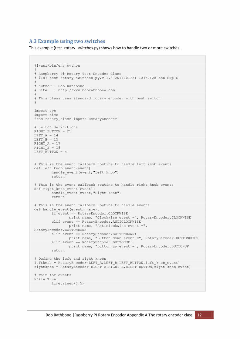
A.3 Example using two switches This example (test_rotary_switches.py) shows how to handle two or more switches.
#!/usr/bin/env python
#
# Raspberry Pi Rotary Test Encoder Class
# $Id: test_rotary_switches.py,v 1.3 2014/01/31 13:57:28 bob Exp $
#
# Author : Bob Rathbone
# Site : http://www.bobrathbone.com
#
# This class uses standard rotary encoder with push switch
#
import sys
import time
from rotary_class import RotaryEncoder
# Switch definitions
RIGHT_BUTTON = 25
LEFT_A = 14
LEFT_B = 15
RIGHT_A = 17
RIGHT_B = 18
LEFT_BUTTON = 4
# This is the event callback routine to handle left knob events
def left_knob_event(event):
handle_event(event,"Left knob")
return
# This is the event callback routine to handle right knob events
def right_knob_event(event):
handle_event(event,"Right knob")
return
# This is the event callback routine to handle events
def handle_event(event, name):
if event == RotaryEncoder.CLOCKWISE:
print name, "Clockwise event =", RotaryEncoder.CLOCKWISE
elif event == RotaryEncoder.ANTICLOCKWISE:
print name, "Anticlockwise event =",
RotaryEncoder.BUTTONDOWN
elif event == RotaryEncoder.BUTTONDOWN:
print name, "Button down event =", RotaryEncoder.BUTTONDOWN
elif event == RotaryEncoder.BUTTONUP:
print name, "Button up event =", RotaryEncoder.BUTTONUP
return
# Define the left and right knobs
leftknob = RotaryEncoder(LEFT_A,LEFT_B,LEFT_BUTTON,left_knob_event)
rightknob = RotaryEncoder(RIGHT_A,RIGHT_B,RIGHT_BUTTON,right_knob_event)
# Wait for events
while True:
time.sleep(0.5)

Bob Rathbone |Raspberry PI Rotary Encoder Appendix B Licences 13
Appendix B Licences The software and documentation for this project is released under the GNU General Public Licence.
The GNU General Public License (GNU GPL or GPL) is the most widely used free software license,
which guarantees end users (individuals, organizations, companies) the freedoms to use, study,
share (copy), and modify the software. Software that ensures that these rights are retained is called
free software. The license was originally written by Richard Stallman of the Free Software
Foundation (FSF) for the GNU project.
The GPL grants the recipients of a computer program the rights of the Free Software Definition and
uses copyleft to ensure the freedoms are preserved whenever the work is distributed, even when
the work is changed or added to. The GPL is a copyleft license, which means that derived works can
only be distributed under the same license terms. This is in distinction to permissive free software
licenses, of which the BSD licenses are the standard examples. GPL was the first copyleft license for
general use.
See http://www.gnu.org/licenses/#GPL for further information on the GNU General Public License.
Acknowledgements Much of the information in this tutorial comes from an excellent article by Guy Carpenter. See:
http://guy.carpenter.id.au/gaugette/2013/01/14/rotary-encoder-library-for-the-raspberry-pi/

Bob Rathbone |Raspberry PI Rotary Encoder Glossary 14
Glossary
GPIO General Purpose IO (On the Raspberry PI)
Top Related