


Languages
Pages
Legal


PROCESS OVERVIEW
Polystrand™ advanced thermoplastic composites combine high strength, unidirectional, continuous fibers with engineered thermoplastic resins to create continuous fiber reinforced thermoplastic (CFRTP) materials that feature exceptional strength-to-weight ratio and high impact resistance.
Overmolding integrates Polystrand tapes and multi-ply laminates into traditional thermoplastic molding processes, such as injection and compression molding, to create locally-reinforced, molded components.
Improve performance, enhance your capability
• Meet higher performance requirements with thermoplastic materials
• Reduce part weight• Achieve rapid cycle times• Differentiate with expanded manufacturing
and product performance capabilities
Dramatically increasing impact resistance and stiffness of molded components—without adding significant weight—means that OEMs can meet increasingly demanding application requirements. For molders, incorporating CFRTP overmolding capabilities expands their product offering, opening the door for increased market share.
Overmolding with Polystrand™ Continuous Fiber Reinforced Thermoplastic CompositesProcessability Meets Performance
Overmolding with Polystrand
CFRTP can enhance the
performance of traditional
thermoplastics or enable
metal replacement in a wide
range of applications.
Read the Rome Snowboard Binding
Case Studybit.ly/34PG0a6
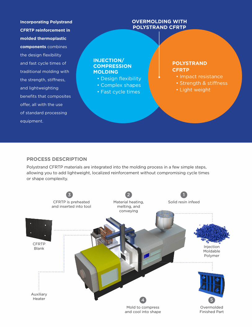
Incorporating Polystrand
CFRTP reinforcement in
molded thermoplastic
components combines
the design flexibility
and fast cycle times of
traditional molding with
the strength, stiffness,
and lightweighting
benefits that composites
offer, all with the use
of standard processing
equipment.
OVERMOLDING WITH POLYSTRAND CFRTP
INJECTION/COMPRESSION MOLDING
• Design flexibility• Complex shapes• Fast cycle times
POLYSTRAND CFRTP
• Impact resistance• Strength & stiffness• Light weight
PROCESS DESCRIPTION
Polystrand CFRTP materials are integrated into the molding process in a few simple steps, allowing you to add lightweight, localized reinforcement without compromising cycle times or shape complexity.
Injection Moldable Polymer
CFRTP Blank
Auxiliary Heater
Overmolded Finished Part
Increase strength and impact resistance. Enable thinner, lighter part design.
Mold to compress and cool into shape
4
CFRTP is preheated and inserted into tool
3Material heating,
melting, and conveying
2Solid resin infeed
1
5
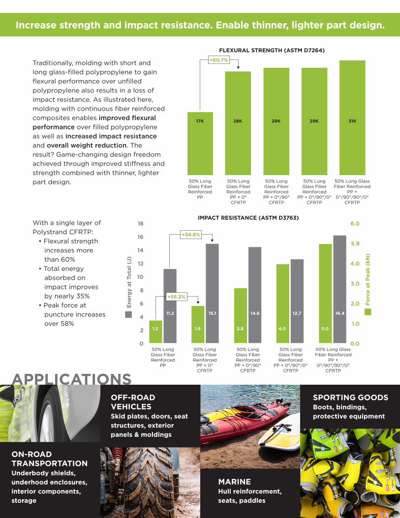
ON-ROAD TRANSPORTATIONUnderbody shields, underhood enclosures, interior components, storage
OFF-ROAD VEHICLESSkid plates, doors, seat structures, exterior panels & moldings
Traditionally, molding with short and long glass-filled polypropylene to gain flexural performance over unfilled polypropylene also results in a loss of impact resistance. As illustrated here, molding with continuous fiber reinforced composites enables improved flexural performance over filled polypropylene as well as increased impact resistance and overall weight reduction. The result? Game-changing design freedom achieved through improved stiffness and strength combined with thinner, lighter part design.
With a single layer of Polystrand CFRTP:
• Flexural strength increases more than 60%
• Total energy absorbed on impact improves by nearly 35%
• Peak force at puncture increases
over 58%
Increase strength and impact resistance. Enable thinner, lighter part design.
SPORTING GOODSBoots, bindings, protective equipment
MARINEHull reinforcement,seats, paddles
50% Long Glass Fiber Reinforced
PP
50% Long Glass Fiber Reinforced
PP + 0° CFRTP
50% Long Glass Fiber Reinforced PP + 0°/90°
CFRTP
50% Long Glass Fiber Reinforced
PP + 0°/90°/90°/0°
CFRTP
17K 28K 29K
50% Long Glass Fiber Reinforced
PP + 0°/90°/0° CFRTP
29K 31K
+60.7%
FLEXURAL STRENGTH (ASTM D7264)
IMPACT RESISTANCE (ASTM D3763)
50% Long Glass Fiber Reinforced
PP
50% Long Glass Fiber Reinforced
PP + 0° CFRTP
50% Long Glass Fiber Reinforced PP + 0°/90°
CFRTP
50% Long Glass Fiber Reinforced
PP + 0°/90°/0° CFRTP
50% Long Glass Fiber Reinforced
PP + 0°/90°/90°/0°
CFRTP
Ene
rgy
at T
otal
(J)
Forc
e at
Pea
k (k
N)
18
16
14
12
10
8
6
4
2
0
6.0
5.9
4.0
3.0
2.0
1.0
0.0
11.2 15.1 14.6 12.7 16.4
1.2 1.9 2.8 4.0 5.0
+58.3%
+34.8%
50% Long Glass Fiber Reinforced
PP
50% Long Glass Fiber Reinforced
PP + 0° CFRTP
50% Long Glass Fiber Reinforced PP + 0°/90°
CFRTP
50% Long Glass Fiber Reinforced
PP + 0°/90°/90°/0°
CFRTP
17K 28K 29K
50% Long Glass Fiber Reinforced
PP + 0°/90°/0° CFRTP
29K 31K
+60.7%
FLEXURAL STRENGTH (ASTM D7264)
IMPACT RESISTANCE (ASTM D3763)
50% Long Glass Fiber Reinforced
PP
50% Long Glass Fiber Reinforced
PP + 0° CFRTP
50% Long Glass Fiber Reinforced PP + 0°/90°
CFRTP
50% Long Glass Fiber Reinforced
PP + 0°/90°/0° CFRTP
50% Long Glass Fiber Reinforced
PP + 0°/90°/90°/0°
CFRTP
Ene
rgy
at T
otal
(J)
Forc
e at
Pea
k (k
N)
18
16
14
12
10
8
6
4
2
0
6.0
5.9
4.0
3.0
2.0
1.0
0.0
11.2 15.1 14.6 12.7 16.4
1.2 1.9 2.8 4.0 5.0
+58.3%
+34.8%
Application design
Modeling & simulation
Prototyping & validation
Material selection
Composite/resin compatibility
Custom formulations
Mold filling analysis
Technical support
Process optimization
PROCESSING
1.866.POLYONE
www.polyone.com
Copyright © 2019, PolyOne Corporation. PolyOne makes no representations, guarantees, or warranties of any kind with respect to the information contained in this document about its
accuracy, suitability for particular applications, or the results obtained or obtainable using the information. Some of the information arises from laboratory work with small-scale equipment
which may not provide a reliable indication of performance or properties obtained or obtainable on larger-scale equipment. Values reported as “typical” or stated without a range do not
state minimum or maximum properties; consult your sales representative for property ranges and min/max specifications. Processing conditions can cause material properties to shift
from the values stated in the information. PolyOne makes no warranties or guarantees respecting suitability of either PolyOne’s products or the information for your process or end-use
application. You have the responsibility to conduct full-scale end-product performance testing to determine suitability in your application, and you assume all risk and liability arising from
your use of the information and/or use or handling of any product. POLYONE MAKES NO WARRANTIES, EXPRESS OR IMPLIED, INCLUDING, BUT NOT LIMITED TO, IMPLIED WARRANTIES
OF MERCHANTABILITY AND FITNESS FOR A PARTICULAR PURPOSE, either with respect to the information or products reflected by the information. This literature shall NOT operate as
permission, recommendation, or inducement to practice any patented invention without permission of the patent owner.
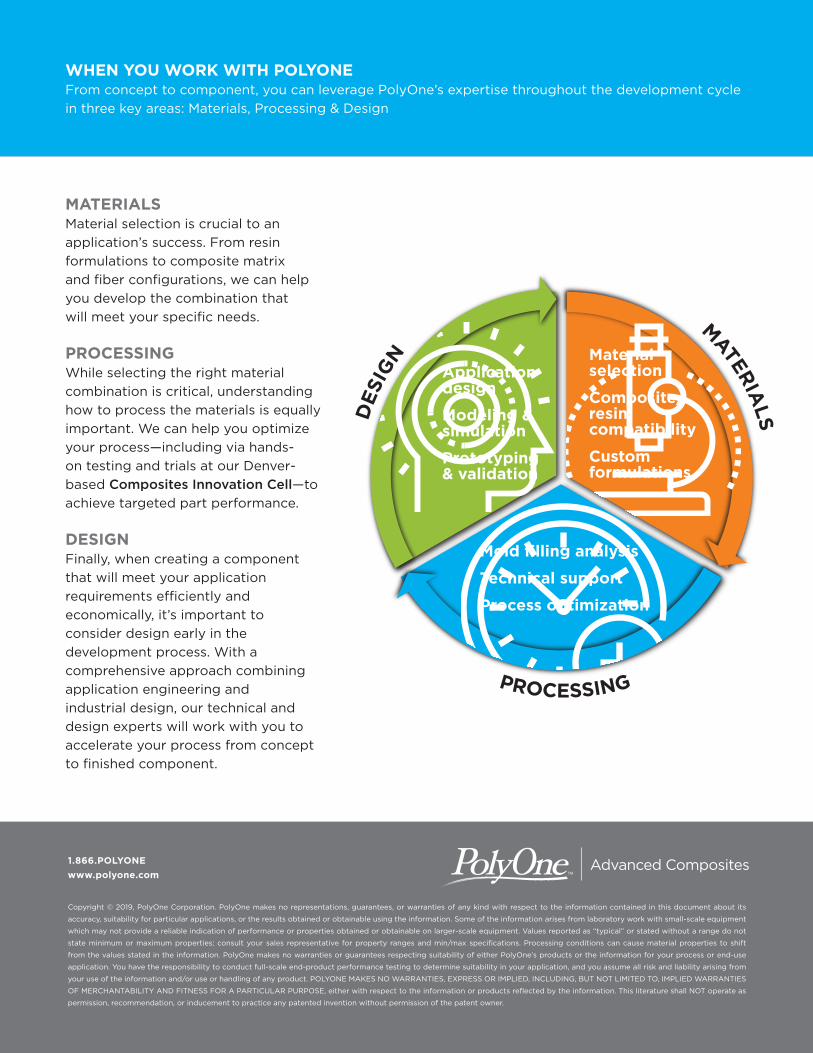
MATERIALSMaterial selection is crucial to an application’s success. From resin formulations to composite matrix and fiber configurations, we can help you develop the combination that will meet your specific needs.
PROCESSINGWhile selecting the right material combination is critical, understanding how to process the materials is equally important. We can help you optimize your process—including via hands-on testing and trials at our Denver-based Composites Innovation Cell—to achieve targeted part performance.
DESIGNFinally, when creating a component that will meet your application requirements efficiently and economically, it’s important to consider design early in the development process. With a comprehensive approach combining application engineering and industrial design, our technical and design experts will work with you to accelerate your process from concept to finished component.
WHEN YOU WORK WITH POLYONEFrom concept to component, you can leverage PolyOne’s expertise throughout the development cycle in three key areas: Materials, Processing & Design
DES
IGN
MATERIALS
Top Related