
![Vertrieb 3.0 lead generation im social web [alliance bliss concept]](https://static.fdocuments.in/doc/165x107/558c5ab7d8b42a4e2c8b4742/vertrieb-30-lead-generation-im-social-web-alliance-bliss-concept.jpg)


Languages
Pages
Legal


Striving to make products that move you.Vacuum Pump Catalogue
D-VG02Dec. 2014
ORION DRY PUMPIntroducing the F Series Lineup. Newly redesigned for even better reliability.
Full Product Index on Page 1.
High-Vacuum Dry PumpKHF series
Combination Dry Pump
CBF series
Heavy DutyStandard Dry Pump KRF series
CompactStandard Dry PumpKRF series

Environmentally Conscious NEW DESIGNWorldwide Forerunner with RoHS Directive Compliance
Designed for Safety・Meets CE Marking Standards (Models with single-phase motors are excluded)・ Special Protective Covering Protects Against Surface Heat and
Contact with Moving Parts.
Established International Market Share

Low Noise Design Long LifeReduced Annoying Low Frequency Noise Vane Life Increased 30%
(compared to previous models)
Annoying low frequency noise (below 500Hz) greatly reduced.Comparison of noise level by frequency of CBF4040-VB and CBX40 operating at 60Hz, 60kPa vacuum and 60kPa compression

● Longer Operating Life Vane Life Increased 30% (KRF 15A, 25A, 40A) Vane Life Increased 20% (KRF 04A, 08A) Vane Life Increased 10% (KRF 70, 110)● Safety Enhanced Design, Environmentally Conscious CE Marking (Not including single-phase models)
and RoHS Directive Certified● Low Noise Design
Normal Capacity Dry PumpKRF series

● Original Twin Cylinder Design ● Safety Enhanced Design, Environmentally Conscious CE Marking & RoHS Directives certified● Improved Ease of Maintenance ● Does Not Require Alignment Adjustments ● Easy To Replace Filter
CombinationDry PumpCBF series
High Vacuum Dry PumpKHF series● Safety Enhanced Design CE Marking Certified (04 models) (Not including single-phase models)● Easy Vane Replacement (KHF14・KHF20)● �Operable from ultimate pressure down to
atmospheric pressure. (KHF14・KHF20)

Air Station 10 〜 15dB Noise Reduction
Multiple pumps and blowers in a singlecabinet for easier pump management
Pump and Blower System Cabinet (Order Req.)
Air Cooled AS135AExhaust Duct Support Water Cooled AS135W
Heat output from enclosed pumpscooled via water-cooled condenser.Zero-Level Heat Output!
Silent BoxKCS seriesMatched to Individual Pump
5 〜 10dB Noise Reduction
KCS110
KCS70
KCS21A,31A,61A

1
Index
Model Nomenclature, Functioning Principles, Sample Applications .....................2・3Pressure Unit Comparison Chart, Pump Pressure Guide,Pressure Units Notes, Conversion Chart, Pump Overview ........................4・5Choosing the Right Pump ........................................................................6 〜 9Pump and Equipment List ...................................................................... 10・11
KM41A .................................................................................................. 12・13KYP Series (Oscillating Piston Pump) ................................................... 12・13KRF Series ............................................................................................ 14・15
KRF Series ...........................................................................................16 〜 19
CBF Series ............................................................................................. 20・21CBX62 .........................................................................................22・23CBXP Series ........................................................................................24 〜 27
KHF Series ............................................................................................ 28・29KHA Series ............................................................................................ 30・31KHH251 ......................................................................................................... 32
KCS Series (Silent Box) .......................................................................33 〜 35AS135 Series (Pump and Blower System Box) ............................................ 36
Accessories ..........................................................................................37 〜 40Safety Precautions and Information .....................................................41 〜 44Energy Savings Proposals ............................................................................ 45
Product Overview
Compact Type
KM41A KYP series KRF series
Standard Type
KRF series
Combination Pumps
CBF series CBX62 CBXP series
KHH251 KHA series KHF series
High Vacuum Models
Operating Environment Support
KCS series AS series
Accessories & Information

2
Mod
el N
omen
clat
ure
Model Nomenclature / Functioning Principles / Sample Applications
ORION DRY PUMPS - ORION IS THE LEADING EXPERT IN OIL-LESS ROTARY VANE PUMP TECHNOLOGY, WITH NEW QUIETER OPERATION AND A LONGER SERVICE LIFE.Since the development of our first oil-less rotary vane pump in 1965, ORION has constantly upgraded vane pump technology so that the state of the art pumps available today provide an oil free system capable of quiet, durable operation.The superb performance and multi-purpose function of the ORION Dry Pump have proven to be indispensable in automated industries, saving time and labor in printing and medical applications, precision high-technology production and office machinery, as well as in food processing.
● ORION Dry Pumps are oil-free for both vacuum and pressure systems, and do not contaminate the work environment and workpieces with oil. These pumps are ideally suited for various applications.
● Low operating sound levels and long service life. Pre-equipped with gauges and controllers. (Some models don't apply.)
● Specially designed wear-resistant, self-lubricating carbon vanes.● High-speed rotating multi-vane for stable suction / exhaust with little fluctuation.
Model Nomenclature
Depending on the model, further variations may exist. Please consult the page of the specific model for further details.
01: Standard 3PH Motor
02: Single Phase Motor
03: No-Motor
04: 400V class, 6 Voltage Motor
Type of Pump: V: Vacuum
B: Blower
VB: Vacuum/Blower
04A, 08A, 15A, 25A, 40A, 70, 110 Pump Flow Capacity m3/h
Model Name
Model Name
KRF □□�-�□□�-�□□
01: 3PH Motor02: Single Phase Motor04: CE Marking Rated Motor
Pump Configuration V: Wide Range VH: High Vacuum Only
08, 14, 20Pump Flow Capacity m3/h
Model Name
CBF □□□□�-�□□□□�-�□□ 01: Standard 3PH Motor 03: No-Motor04: 400V class, 6 Voltage Motor
Pump Configuration
2nd Pump Flow Capacity m3/h
1st Pump Flow Capacity m3/h
KHF □□�-�□□�-�□□
VBVB : Vacuum/Blower Vacuum/Blower VB : Vacuum/Blower VV : Vacuum/Vacuum BB : Blower/Blower

3
● A rotor is placed eccentrically within a cylinder. All components are precisely manufactured and adjusted to achieve minimum clearances. Vanes are inserted into slots in the rotor and are free to slip in and out within the walls of the cylinder. As the rotor turns, the vanes slide out and are kept in constant contact with the cylinder wall due to centrifugal force.● As the rotor turns, the volume of space between the vanes changes.
As shown in the illustration, when the rotor spins from state 1 to 2, the increase in volume at the intake creates a vacuum. As the volume of space between the vanes decreases during the cycle, the air trapped between the vanes is compressed as shown between states 2 and 3. Finally between states 3 and 4 the compressed air is allowed to escape through the air outlet. The process repeats as the rotor continuously rotates in order to achieve a constant air flow from inlet to outlet.● A four-vane-type pump provides intake/discharge 4 times in a single rotation. Defining volume at the end of intake as V(L),
and rotation speed as N(rpm), 4VN(L) of air is discharged per minute. This theoretical value is what's known as the designed pumping capacity.
Func
tioni
ng P
rinci
pals
Sam
ple
App
licat
ions
Functioning Principles
INOUT
Cylinder
Vacuum Pump Process
1.suction
2.end of suction / startof compression
3.end of compression /start of discharge
4.discharge
● Printing Machines ● Binding Machines ● Photographic Processing ● Insertion Machinery ● Vacuum Lift ● Vacuum Chuck ● Robotic Arm ● Packaging Machines ● Vacuum Forming ● Computer Applications ● Paper Counter ● Labeling Machine ● Parts Feeder ● Dust Gas Sampling ● Vacuum Tweezer/Pickup ● Air Bearing ● Oxygen Production ● Medical / Health Care Equipment ● Business Machinery ● Other Automation Machinery Applications
Sample Applications
Vacuum FormingAgitatingEquipment
Vacuum LiftLabeling MachineAutomated Machinery
Printing Machine Binding Machine Photo Processing IC/Component Lift, Placement on PC Board
CBXP □□��□□��□�-�□□�-�□□
Model Nomenclature
03 02,03
Hour meter
02: Casters03: Casters, Hour meter
Type of Pump: V: Vacuum B: Blower VB: Vacuum/Blower
Model Revision Number
2nd Pump Flow Capacity m3/h
1st Pump Flow Capacity m3/h
Model Name

4
Pump Pressure Guide
Pressure Unit Comparison / Pump Pressure Guide / Pressure Units Notes / Model List
Pressure Units Comparison Chart
60
606060
60 CBXP □ A, □ B-BBCBXP □ A, □ B-VV70
707070
80CBXP□B-VBCBXP □ B-VB60
60
606060
CBXP□A-VBCBXP □ A-VBCBX62A :No.2 50CBX62A :No.2 35CBX62A :No.120CBX62A :No.155
CBX62CBX62CBF1515/2525/4040CBF1515/2525/4040KRF70-B/110-BKRF70-V/110-V
KRH10808080
75
KRF70-BHKRF70-VHKRF25A/40AKRF25A/40AKRF08A/KRF15AKRF08A/KRF15AKRF04AKRF04A 5055
55252525
2510
10
Maximum Exhaust ResistanceMaximum Exhaust ResistanceMaximum Exhaust ResistanceMaximum Exhaust ResistanceMaximum Exhaust ResistanceMaximum Exhaust Resistance
KM41A
KHF14-V/20-VKHF08-VH/KHA100200/400/750
KHH251KYP40-101KYP90-101
KYP45H-1012.7[abs]8[abs]
10.7[abs][abs]1.38[abs]8[abs]
48[abs]
Absolute Vacuum Vacuum: kPa Atmospheric Pressure Positive Pressure: kPa
Unit (positive pressure): barUnit: bar
SI Standard (Pascals):kPaSI Standard (Pascals):kPa
Millimeters of mercury Pressure:kgf/cm2
Unit: bar
SI Standard Unit (Pascals): kPa [abs]
Unit: Torr
1.013
101.3
101.3 93.3 86.7 73.3 53.3 46.766.776 60 40 2033.3 26.7 13.3 6.7 9.8 19.6 29.4 39.2 58.8 68.6 78.4 88.2 9849080
90 80 70 60 50 40 30 30 40 50 60 70 80 90 9820 2010 100
100
100
0
0
0 8 13.3 20 26.7 40 48 53.3 60 66.7 80 93.3 101.3
760700600500450400360300200150100600
1.3
10 15
210 20 30 40 50 60 70 80 90 100
0.1 0.2 0.3 0.4 0.5 0.6 0.7 0.8 0.9 1.013
750
760 700 650 600 550 500 450 400 350 300 250 200 150 100 50 0.1 0.2 0.3 0.4 0.5 0.6 0.7 0.8 0.9 1.00
680 630 570
90.7 84
0.9 0.8 0.7 0.6 0.5 0.4 0.3 0.3 0.4 0.5 0.6 0.7 0.8 0.9 0.980.2 0.20.1 0.101
Pres
sure
Uni
t Com
paris
on P
ump
Pres
sure
Gui
de
Pres
sure
Uni
ts N
otes
Elevation Correction Value
Elevation(m) Correction Value(kPa)100 1.2200 2.4300 3.6400 4.7500 5.9600 7.0700 8.1800 9.3900 10.4
1,000 11.5
● The elevation correction value is based on the elevation where the pump is operated and this value is to be subtracted from the degree of vacuum. � �When operating at atmospheric pressure in areas of high elevation, there will be a difference in the actual degree of vacuum compared to operating at atmospheric pressure at sea level. Accordingly, the upper limit of the continuous degree of vacuum will be lower, and the pump should be operated within the adjusted range. Operating the pump at a degree of vacuum exceeding this adjusted upper limit will shorten the operating lifespan of the pump and can also result in breakdown of the pump. For the same reason, the actual ultimate vacuum will also be lower than the value noted in the specifications.� ��Example: For operation at an elevation of 500m: The continuous degree of vacuum of the KRF40A would be in the range of 80-5.9 = 74.1 kPa.

5
ModelSpecification
ApplicationsModel
(Three phase- 200V)
Continuous oper-ative vacuum
(kPa )
Designed pumpingcapacity
L/min(50Hz)
Three-phase motor
Single-phase motor
Without
motor
Other voltage,3 phase motor
CE M
arking
UL
RoH
S D
irective
Gauge
Controller
OperationalSound
PageOperational( maximum)
50Hz200V
60Hz200-220V
50/60Hz100V200V
400Vclass
Silent BoxWithout With
KRF08A V
● Printing / Binding ● Automation● Analytical
instrument● Packaging※ Vacuum
requirement 55〜 80kPa
● Aeration、Blower、※ Discharge
pressure requirement 50〜 70kPa
08A-V-01 60(75)135 ○ ○ ○ ○ MTO ○ MTO ○ ○ ○
60 / 61 50 / 52P14B 08A-B-01 60(70) 64 / 67
VB 08A-VB-01 60(75) in total 60 / 61KRF15A V 15A-V-01A 60(75)
235 ○ ○ ○ ○ MTO ○ MTO ○ ○ ○60 / 62 54 / 56
P16B 15A-B-01A 60(70) 64 / 65VB 15A-VB-01A 60(75) in total 60 / 62
KRF25A V 25A-V-01A 60(80)405 ○ ○ ○ ○ MTO ○ MTO ○ ○ ○
62 / 64 54 / 56P16B 25A-B-01A 60(70) 65 / 67
VB 25A-VB-01A 60(80) in total 62 / 64KRF40A V 40A-V-01A 60(80)
575 ○ ○ ー ○ MTO ○ MTO ○ ○ ○66 / 67 54 / 56
P16B 40A-B-01A 60(70) 68 / 70VB 40A-VB-01A 60(80) in total 66 / 67
KRF70 V 70-V-01A 601130 ○ ○ ー ○ MTO ○ MTO ○ ○ ○
67 / 68 57 / 58P18B 70-B-01A 60 74 / 76 58 / 60
VB 70-VB-01A 60 in total 67 / 68KRF110 V 110-V-01 60
1850 ○ ○ ー ○ MTO ○ MTO ○ ○ ○74 / 75 58 / 59
P18B 110-B-01 60 76 / 77 58 / 60VB 110-VB-01 60 in total 74 / 75
KHA100 ● Chip inserter ● Small parts
assembly● Photo
engraving● Packaging● Food process● Vacuum
forming※ Vacuum
requirement 60〜 93kPa
100-301 Photo:400
From ultimate pressure to
48(abs)55 ○ ○ ○ ー MTO ー MTO ー Option Option 60 / 61 47 / 51 P30
KHF08 08-VH-0108-VH-04 (CE)
From ultimate pressure to
48(abs)125 ○ ○ MTO MTO MTO
○04 model
MTO ー Option Option 64 / 67 P28
KHF14 14-V-0114-V-04 (CE)
Overallrange 230 ○ ○ MTO MTO MTO
○04 model
MTO ー Option Option 66 / 68 P28
KHF20 20-V-01A20-V-04 (CE)
Overallrange 340 ○ ○ MTO MTO MTO
○04 model
MTO ー Option Option 67 / 69 P28
Uni
ts C
onve
rsio
n C
hart
Mod
el L
ist
Units Conversion Chart
Model List
※ Single phase and models without motors.※ ○ indicates standard equipment.
Vacuum Units Pressure (Gauge Pressure)From To kPa mmHg mbar1 kPa → 1 7.5 101 mmHg → 0.1333 1 1.3331 mbar → 0.1 0.75 1
Vacuum Units Absolute PressureFrom To kPa [abs] Torr atm mbar [abs]1 kPa [abs] → 1 7.5 9.87×10 ー 3 101 Torr → 0.1333 1 1.316×10 ー 3 1.3331 atm → 1.013×10² 760 1 1.013×10³
1 mbar [abs] → 0.1 0.75 9.87×10 ー 4 1
Pressure Units Exhaust Pressure (Gauge Pressure)From To kPa kgf/cm2 psi mbar1 kPa → 1 1.02×10 ー 2 1.45×10 ー 1 101 kgf/cm2 → 98.07 1 14.223 9.807×10²
1 psi(lb/in) → 6.89 7.031×10 ー 2 1 68.91 mbar → 0.1 1.02×10 ー 3 1.45×10 ー 2 1
Volumetric UnitsFrom To cfm m3/h L/min L/s m3/s1 cfm(ft3/min) → 1 1.6992 28.32 0.472 4.72×10 ー 4
1 m3/h → 0.589 1 16.67 0.278 2.78×10 ー 4
1 L/min → 0.0353 0.06 1 0.0167 1.67×10 ー 5
1 L/s → 2.119 3.6 60 1 10 ー 3
1 m3/s → 2119 3600 60000 1000 1
Pressure Units NotesPlease note that the same units can be used to indicate atmospheric or absolute pressure standard measurements based on the individual case.Please be careful regarding these units.
※ mmHg and torr units cannot be used in business transactions.
Absolute Vacuum Vacuum Positive PressureAtmospheric PressureDegree of Vacuum
kPa, mmHg kPa
kPa[abs] mbar[abs] torr
Degree of Vacuum Atmospheric Pressure Standard Absolute Pressure Standard
Notes ・Atmospheric Pressure regarded as "0" Also known as "gauge pressure". ・We refer to it as "degree of vacuum." A '-' (minus) sign will not be indicated as it is an absolute value.
・Absolute vacuum will be indicated as "0". ・Indicated as pressure.
Units ・kPa ・mmHg ・kPa[abs] ・mbar[abs] ・torr

6
Sele
ctio
n of
Sui
tabl
e Pu
mp
Selection of Suitable Pump
1. When there is no pressure drop and a vacuum controller is used.Specific pump choice should take into consideration the variety of conditions in which it will be used. Following are typical configurations based on a simplified set of conditions for the sake of example.
In the case of vacuum lifting, a comparison of grabbing force along with the degree of vacuum, and the size of the area being grabbed.
Note: The precise formula is F=A × P / 98.1kPa, but for practical use, we assume 101.3kPa ≒ 1gkf/cm2.
F: Suction force (kg)A: Suction area of vacuum cup (cm2)P: Operational vacuum (kPa)
Equation (i) F = A× P101.3
Graphed, the relationship between these variables is as below: Conversion formulas of pressure related units:
Suction Force F (kg)
10
5
0
P: Opera
tional v
acuum (kP
a)
0 5 10A: Suction area of vacuum cup (cm2)
100kPa
80kPa
60kPa
40kPa
20kPa
Lifting and Conveying Objects
When choosing a pump to be used with equipment that repeatedly grabs/moves/releases objects, the pump must be chosen that can attain the required pressure within the required time constraints. Please refer to this example.
ExampleUse: Vacuum liftObject conveyed: Aluminum (relative density of 2.7)Dimensions: 20cm×30cm×15cm(L×W×H)Weight: approx. 25kgOne processing cycle starts at ① and ends at ⑧ .
Task and time ① To lower 0.5s ② To grab 0.6s ③ To rise 0.5s④ Move right 0.75s ⑤ To lower 0.25s⑥ To release 0.4s ⑦ To rise 0.25s ⑧ Move left 0.75sPiping: 1 1/2B×300cm (from pump to vacuum cup.)Vacuum cup volume: 100cm3
① ③
②
⑥
⑤ ⑦
⑧
④
A BmmHg kPa A=B×7.5 B=A/7.5inHg kPa A=B/3.387 B=A×3.387atm kPa A=1 ー B/101.3 B=101.3×(1 ー A)mbar kPa A=B×10 B=A/10mmAq kPa A=B×102 B=A/102Torr kPa A=760 ー (B×7.5) B=(760 ー A)/7.5kPa[abs] kPa A=101.33 ー B B=101.33 ー A
7
4.162
Sele
ctio
n of
Sui
tabl
e Pu
mp
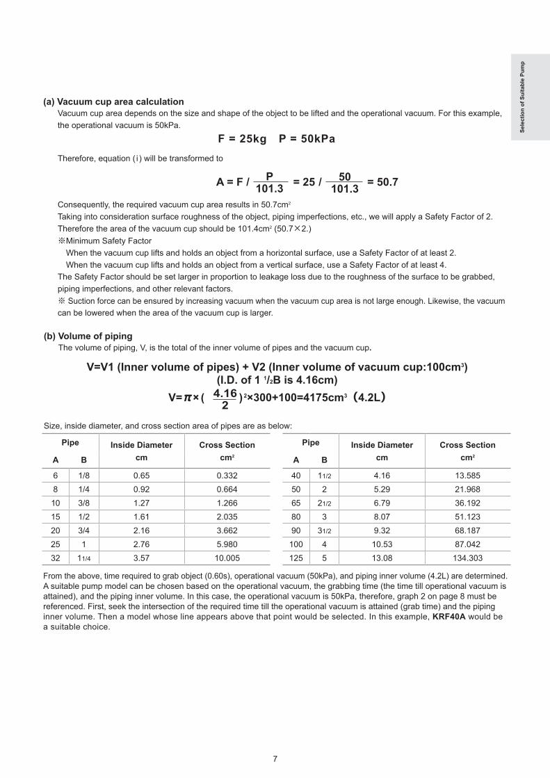
(a) Vacuum cup area calculationVacuum cup area depends on the size and shape of the object to be lifted and the operational vacuum. For this example, the operational vacuum is 50kPa.
F = 25kg P = 50kPaTherefore, equation ( i ) will be transformed to
A = F / = 25 / = 50.7
Consequently, the required vacuum cup area results in 50.7cm2
Taking into consideration surface roughness of the object, piping imperfections, etc., we will apply a Safety Factor of 2. Therefore the area of the vacuum cup should be 101.4cm2 (50.7×2.)※Minimum Safety Factor When the vacuum cup lifts and holds an object from a horizontal surface, use a Safety Factor of at least 2. When the vacuum cup lifts and holds an object from a vertical surface, use a Safety Factor of at least 4.The Safety Factor should be set larger in proportion to leakage loss due to the roughness of the surface to be grabbed, piping imperfections, and other relevant factors.※ Suction force can be ensured by increasing vacuum when the vacuum cup area is not large enough. Likewise, the vacuum can be lowered when the area of the vacuum cup is larger.
P101.3
50101.3
(b) Volume of pipingThe volume of piping, V, is the total of the inner volume of pipes and the vacuum cup.
From the above, time required to grab object (0.60s), operational vacuum (50kPa), and piping inner volume (4.2L) are determined. A suitable pump model can be chosen based on the operational vacuum, the grabbing time (the time till operational vacuum is attained), and the piping inner volume. In this case, the operational vacuum is 50kPa, therefore, graph 2 on page 8 must be referenced. First, seek the intersection of the required time till the operational vacuum is attained (grab time) and the piping inner volume. Then a model whose line appears above that point would be selected. In this example, KRF40A would be a suitable choice.
V=V1 (Inner volume of pipes) + V2 (Inner volume of vacuum cup:100cm3)(I.D. of 1 1/2B is 4.16cm)
V=π× ( ) 2×300+100=4175cm3(4.2L)
Size, inside diameter, and cross section area of pipes are as below:
Pipe Inside Diametercm
Cross Sectioncm2A B
6 1/8 0.65 0.3328 1/4 0.92 0.66410 3/8 1.27 1.26615 1/2 1.61 2.03520 3/4 2.16 3.66225 1 2.76 5.98032 11/4 3.57 10.005
Pipe Inside Diametercm
Cross Sectioncm2A B
40 11/2 4.16 13.58550 2 5.29 21.96865 21/2 6.79 36.19280 3 8.07 51.12390 31/2 9.32 68.187100 4 10.53 87.042125 5 13.08 134.303

8
Time till operational vacuum is attained (s)
Volume of piping (L)
Time till operational vacuum is attained (s)
Volume of piping (L)
Time till operational vacuum is attained (s)
Volume of piping (L)
Time till operational vacuum is attained (s)
Volume of piping (L)
0.2 0.4 0.6 0.8 1.0
40
30
20
10
0
KRF110
KRF70
KRF40A
KRF25A
KRF15AKRF08A
50Hz 60Hz
0.2 0.4 0.8 1.00.6
KRF110
KRF70
KRF40A
KRF25A
KRF15AKRF08A
50Hz
0
5
10
15
20
25
30
↑
4.2
60Hz
0.2 0.4 0.6 0.8 1.0
50Hz 60Hz
KRF110
KRF70
KRF40A
KRF25A
KRF15AKRF08A
25
20
10
0
5
15
0.2 0.4 0.6 0.8 1.0
KRF110
KRF70
KRF40A
KRF25A
KRF15AKRF08A
0
5
10
15
50Hz 60Hz
Sele
ctio
n of
Sui
tabl
e Pu
mp
Selection of Suitable Pump
(c) Selection may also be done from calculations and pump performance charts. Below is an example using the same case as (b)
S: Flow demand (L/min)V: Piping inner volume 4.2L⊿ t: Time to grab 0.6s
341 L/min is figured from the above.From the above equation we conclude that the required flow demand is 341 L/min.On the vacuum performance graph (Graph 5) we select the point at the intersection of the flow rating of 341 and on the horizontal axis, the midpoint between P1 and P2, which is 25. The nearest line above this point indicates KRF40A is a suitable model.
P0: Ultimate vacuum of pump 90kPaP1: Initial pressure inside pipes 0kPaP2: Vacuum (Suction force) 50kPa
Equation (ii) S= ×log138.2×V⊿ t
P0-P1P0-P2
Graphs for Pump SelectionGraph 1 (at 40kPa) Graph 2 (at 50kPa)
Graph 3 (at 55kPa) Graph 4 (at 60kPa)

9
0
100
200
300
Vacuum
Vacuum (V)
KRX1-SS
KRF40
KRF25
KRF15
60Hz 50Hz
400
500
600
50 40 30 20 10 0 kPa
Exhaust Pressure
Blower (B)
0 60 kPa10 20 30 40 50
341
60
KRF08A
KRF40A
KRF25A
KRF15A
Flow (L/m
in)
↑25
Sele
ctio
n of
Sui
tabl
e Pu
mp
■ Total pressure loss of piping (ΣPi) ΣPi = p1 + p2 + p3 + p4 +…+ pn pi:pressure loss of each pipe■ Pressure loss of each section (each piping size) Pi = 7.15×L×Q
2÷D
5
pi:Pressure loss of each pipe. (kPa) L :Piping Length (m) The pressure loss is in proportion
to the length of the piping. Calculate the piping length from
the piping layout.
Q :Flow rate through the piping (L/min) the pressure loss will be in proportion to the square of the
flow rate. The flow rate is regarded as the air capacity of the selected vacuum pump at 0kPa.
D :Inner diameter of the piping (diameter) (mm) The pressure loss is inversely proportional to the inner diameter
of the piping raised to the fifth power. when the inner diameter becomes larger, pressure loss is greatly reduced.
Regarding Pressure Loss
2. When there is pressure drop and a vacuum controller is not used.Influences from various conditions must be considered in choosing an appropriate pump. Plain and simple methods are described here with examples of typical applications.
S: Flow demand (L/min)V: Piping inner volume (L)⊿ t : Time to grab 0.6sP0: Ultimate vacuum of pump (kPa)P1: Initial pressure inside pipes (kPa)P2: Vacuum (suction force) (kPa)
(ii) Even though the calculation is the same as in equation (ii), S-flow demand is not defined in the same way. Please refer to the table below.
S= ×log138.2×V⊿ t
P0-P1P0-P2
Graph 5 (Performance curve)
Vacuum controller used
SNo pressure loss With pressure loss
At intermediate point between P1 and P2 At intermediate point between pressure drop and P2
Vacuum controller not used
SNo pressure loss With pressure loss
At P1 At pressure drop

10
Model ListStandard Optional
Mod
el L
ist
Note: Please refer to product page in this catalogue for further product specifications and information.
Model
Pump N
o.
Vacuum use (V)
Blow
er use (B)
Vacuum & Blow
er (VB)
Drive
Com
pound gauge type A / type D
Main equipment
Vacuum controller
Pressure controller
Filter case
Oil separator
Water separator
Clean filter
After cooler
Vacuum sw
itch
Separated
Direct-coupled
type D
type A
Compact KM KM41A-101 VC10
Oscillating PistonKYP
40-101-G1 90-101-G1 45H-101-G1
CompactStandard
ModelKRF
04A-V-01/02A VC32 RA-05A-V,05A-M RA31 RA41 RA53S 04A-B-01/02A PC32 RA-05A-S,05A-B RA53D 04A-VB-01/02A VC32 PC32 RA-05A-V,05A-B RA31 RA41 RA53S,D 08A-V-01/02A VC32 SDF25(V) RA31 RA41 RA53S 08A-B-01/02A PC32 SDF15(B) RA53D 08A-VB-01/02A VC32 PC32 SDF25(VB) RA31 RA41 RA53S,D
StandardModelKRF
15A-V-01A/02/04 VC63 SDF25(V) RA31 RA41 RA53S 15A-B-01A/02/04 PCA6 SDF15(B) RA53D 15A-VB-01A/02/04 VC63 PCA6 SDF15(VB) RA31 RA41 RA54D 25A-V-01A/02/04 VC63 SDF25(V) RA31 RA41 RA54S 25A-B-01A/02/04 PCA6 SDF25(B) RA54D 25A-VB-01A/02/04 VC63 PCA6 SDF15(VB) RA31 RA41 RA54S,D 40A-V-01A/04 VC63B SDF40(V) RA31 RA41 RA55S 40A-B-01A/04 PCA6 SDF40(B) RA55D 40A-VB-01A/04 VC63B PCA6 SDF40(VB) RA31 RA41
Heavy DutyStandard
ModelKRF
70-V-01A/04 VC81 VFF70MFF70 RA32 RA42 RA56S
70-B-01A/04 PCA8 SFF70PSF70 RA56D
70-VB-01A/04 VC81 PCA8 VFF70PSF70 RA32 RA42 RA56S,D
70-VH-01A/04 VC81 VFF70MFF70H RA32 RA42 RA56S
70-BH-01A/04 PCA8 SFF70PSF70H RA56D
70-VBH-01A/04 VC81 PCA8 VFF70PSF70H RA32 RA42 RA56S,D
110-V-01/04 VC100B VFF110MFF110 RA57S
110-B-01/04 PCA10 SFF110PSF110 RA57D
110-VB-01/04 VC100B PCA10 VFF110PSF110 RA57S,D
CombinationPumpCBF
1515-VB-01/041 VC63 SDF25(V) RA31 RA41 RA53S2 PCA6 SDF15(B) RA53D
1515-VBVB-01/041 VC63 PCA6 SDF25(VB) RA31 RA41 RA53S,D2 VC63 PCA6 SDF25(VB) RA31 RA41 RA53S,D
1515-VV-01 1,2 VC63 SDF25(V) RA31 RA41 RA53S 1515-BB-01 1,2 PCA6 SDF15(B) RA53D
2525-VB-01A/041 VC63 SDF25(V) RA31 RA41 RA54S2 PCA6 SDF25(B) RA54D
2525-VBVB-01A/041 VC63 PCA6 SDF25(VB) RA31 RA41 RA54S,D2 VC63 PCA6 SDF25(VB) RA31 RA41 RA54S,D
2525-VV-01A 1,2 VC63 SDF25(V) RA31 RA41 RA54S 2525-BB-01A 1,2 PCA6 SDF25(B) RA54D
4040-VB-01/041 VC63B SDF40(V) RA31 RA41 RA55S2 PCA6 SDF40(B) RA55D
4040-VBVB-01/041 VC63B PCA6 SDF40(VB) RA31 RA41 RA55S,D2 VC63B PCA6 SDF40(VB) RA31 RA41 RA55S,D
4040-VV-01 1,2 VC63B SDF40(V) RA31 RA41 RA55S 4040-BB-01 1,2 PCA6 SDF40(B) RA55D

11
※1 Adjustable range of vacuum : 28 〜 48kPa [abs]. ※2 Adjustable range of vacuum : 21 〜 48 kPa [abs]. ※3 Adjustable range of vacuum : 21kPa [abs] and over. ※Please note that there may be different part numbers for parts with the same part name.
Mod
el L
ist
Model
Pump N
o.
Vacuum use (V)
Blow
er use (B)
Vacuum & Blow
er (VB)
Drive
Com
pound gauge type A / type D
Main equipment
Vacuum controller
Pressure controller
Filter case
Oil separator
Water separator
Clean filter
After cooler
Vacuum sw
itch
Separated
Direct-coupled
type D
type A
CombinationPumpCBX
62-G11 VC81 VFS8A MFS8A RA32 RA42 RA56S
2 PCA8 SFS8A PSS8A RA56D DA61
62A-G11 VC81 PCA8 VFS8A PSS8A RA32 RA42 RA56S・D DA61
2 VC81 PCA8 SFS8A PSS8A RA32 RA42 RA56S・D DA61
CombinationPump
One-PackageCBXP
6070A-VB-021 VC81 VFS8A MFS8A RA32 RA42 RA56S
2 PCA8 SFS8A PSS8A RA56D
8080B-VB-02/031 VC81 VFS8A MFF70 RA32 RA42 RA56S
2 PCA10 SFS8A PSF70 RA57D
90110B-VB-02/031 VC100A VFS8A MFF70 RA32 RA57S
2 PCA10 SFF110 PSF110
6060A-VV-02 1,2 VC81 VFS8A MFS8A RA32 RA42 RA56S
8080B-VV-02/03 1,2 VC81 VFS8A MFF70 RA32 RA42 RA56S
9090B-VV-02/03 1,2 VC100A VFS8A MFF70 RA32 RA57S
110110B-VV-02/03 1,2 VC100B VFF110 MFF110
6060A-BB-02 1,2 PCA8 SFS8A PSF8A RA56D
8080B-BB-02/03 1,2 PCA8 SFS8A PSF70 RA56D
9090B-BB-02/03 1,2 PCA10 SFS8A PSF70 RA57D
110110B-BB-02/03 1,2 PCA10 SFF110 PSF110
Direct CoupledMotor
High VacuumKHF
08-VH-01 VC32※2 RA31 RA53S
14-V-01 VC63※3 RA31 RA53S
20-V-01 VC63※3 RA31 RA54S
High VacuumKHA
100-301-G1 VC32※1 RA31 RA53S
200-301A-G1 VC32※2 RA31 RA53S
400-301A-G1 VC63※2 RA-05A-V RA31 RA53S
750-301-G1 VC63※2 RA-05A-V RA31 RA54SHigh VacuumKHH 251-101 RA31

12
single phase 3 phase
Compact KM Model Compact Oscillating Piston KYP Series
Continuous operating vacuum: 55kPa or lowerFlow rate: 29L/min (60Hz)
Ultimate pressure: 10.7 〜 2.7kPa [abs]Flow rate: 33 〜 85L/min (60Hz)
KM41A-101-G1KYP90-101-G1
KYP40-101-G1 KYP45H-101-G1
KYP FeaturesKM Features
● Free rotor drive -- no side adjustment necessary.● Easy Maintenance● Oil free pumps operate without oil so your working
environment and equipment stay free from oil contam-ination.
● Can be hooked up directly to rubber or vinyl hoses.
● Oil Free: Built with a specialized resin cap seal.● Low Noise / Light Weight: 53dB (reference only),
Aluminium Casing Integrated Models● Easy Maintenance
KM Specifications
※1 Designed pumping capacity: Theoretical value calculated from cylinder volume. Refer to "Performance Data" for actual flow rate. ※2 Operation not allowed at ultimate vacuum. For model selection purposes only. ※3 Operable range of vacuum (pressure). ※4 Operating noise measured on a new pump with an ORION recommended motor running at normal vacuum/pressure conditions. Operating noise levels are from a position of 1m in front of the unit and at a height of 1m. ※ A compound gauge and vacuum controller are not included as standard equipment. Install a compound gauge and vacuum controller VC10 on the vacuum piping before the filter and use at a normal degree of vacuum. ※ Operating environment (inlet air) conditions: air temp: 0 〜 40℃ , humidity: normal levels (65±20%). ※ Allowable intermittent power supply voltage fluctuation range is ±10% of the specified voltage; allowable sustained supply voltage fluctuation range is ±5% of the specified voltage. ※Please install an overload protection device (such as a thermal relay). Setting guideline: Use the current rating listed on the motor nameplate as a guide. ※ For detailed specifications, please refer to the specifications sheet.
KYP Specifications
※1 Designed pumping capacity: Theoretical value calculated from cylinder volume. Refer to "Performance Data" for actual flow rate. ※2 Pump can be continuously operated at the maximum attainable vacuum. ※3 Operating noise level measured on a new pump with the standard built-in ORION motor. Operating noise levels are from a position of 1m in front of the unit and at a height of 1m. ※ Operating environment (inlet air) conditions: air temp: 7 〜 40℃ , humidity: normal levels (65±20%). ※ Allowable intermittent power supply voltage fluctuation range is ±10% of the specified voltage; allowable sustained supply voltage fluctuation range is ±5% of the specified voltage. ※ Please install an overload protection device (such as a thermal relay). Setting guideline (may vary depending on the specific application): KYP40: 4.3A@50Hz, 2.1A@60Hz. KYP90/KYP45H: 3.8A@50Hz, 3.4A@60Hz. ※ For detailed specifications, please refer to the specifications sheet.
Single phase 3 Phase model
Model Designed pumpingcapacity
Ultimatepressure
(min.)
Air inlet/outlet
port diameter
Voltage Standard motor current rating
Noiselevel
Motor Mass
ASingle phase Single phase dB※3
L/min ※1 kPa [abs]※2
100V 100V Single phase kg50Hz 60Hz 50/60Hz 50/60Hz 50Hz 60Hz kW Single phase
KYP □ - □ - □40-101-G1 28 33 10.7 Rc1/4 ○ 3.0/1.9 48 52 0.15 7.590-101-G1 75 85 8.0 Rc1/4 ○ 3.2/3.1 52 52 0.25 1045H-101-G1 40 47 2.7 Rc1/4 ○ 3.0/2.7 51 53 0.25 10
Model Designed pumpingcapacity
Ultimate vacuum
Continuously operational
vacuum
Suction/exhaust
port diameter
Voltage Standard motorcurrent rating
A
Noiselevel
Motor Mass
Over:kPa※2
Single phase 3 phase Single phase 3 phase kgL/min ※1
Under:kPa ※3
100V 100/200V 200V 220V 100V 200V 200V 220V dB※4 Single
phase 3 phase50Hz 60Hz 50Hz 60Hz 50/60Hz 60Hz 50/60Hz 60Hz 50Hz 60Hz kW
KM41-A-101-G1 24 29 67 75 55 Hose nippleOutside diameter : φ10 ○ ー ー ー 1.1/
1.2 ー ー ー 60 61 0.06 4.6 ー
Com
pact
KM
Ser
ies

13
φ27
1610
(22)
M6
Included rubber shock absorber (Same for all models)
Ring terminal1.25-4 Silencer
255
213
279
(314)4-φ7
8
176
191
(195
)
40
(500
)
89
106
129
Rc 1/4INLET
101
(43)
(158
)
KYP90-101-G1
KYP40-101-G1
SilencerRing terminal1.25-4
4-φ7
8
89
106
129
(500
)
40
176
191
(195
)
129
143
201
(236)
(158
)
101
(43)
INLET Rc 1/4
KYP45H-101-G1
Ring terminal1.25-4
4-φ7
89
106
129
8
176
191
(195
)
(500
)
20
(314)
279
213
255Silencer
Rc 1/4INLET
101
(43)
(158
)
KM41A-101-G1
Hose nippleINLET
(75)31
184
160
(221)
(21)
(300
)
181
161
3215
194
130
104
9
12
Outside Dimensions (Units:mm)
Com
pact
KM
Ser
ies
Performance Data ( 50Hz 60Hz )
40
20
0
Vacuum (V)
KM41A-101
Vacuum (kPa)
※ 1atm. 20℃
60 50 40 30 20 10 0
Flow R
ate (L/min)
Flow R
ate (L/min)
KYP40 KYP45H
Vacuum (V)
KYP90
40
40
50
1010
20
20
30
30
0 0
80
100
20
40
60
0※1 atm. 20℃ ※1 atm. 20℃ ※1 atm. 20℃
Pressure (kPa [abs] ) Pressure (kPa [abs] ) Pressure (kPa [abs] )0 0 010 10 1020 20 2030 30 3040 40 4050 50 5060 60 6070 70 7080 80 8090 90 90100 100 100

14
Compact Standard Pump KRF Series
Com
pact
Sta
ndar
d Pu
mp
KR
F Se
ries
Continuous Operative Vacuum KRF04A: max. 55kPa KRF08A: Recomm. 60kPa or below (max. 75kPa) Continuous Operative Pressure KRF04A: max. 50kPa KRF08A: Recomm. 60kPa or below (max. 70kPa)Flow rate: 75 〜 155L/min(60Hz)CE Marking Certified ※1RoHS Directive Compliant
KRF04A-V-01 KRF08A-V-01
Features Applications
● Proven Design, Environmentally Friendly ... CE Marking Certified ※1● Low Noise ...... Reduced Noise Design quieter by 2〜 5dB (compared
with our earlier models.)● Long Life ... New blade material yields an increase of 20% (compared
with our earlier models.)
● Vacuum Source for automation equipment, analysis equipment, packaging equipment, printing equipment, book making equipment, etc.
Specifications Single phase motor 3 phase motor
※1 Models with single phase motors and models without motors are excluded. ※2 Designed pumping capacity: Theoretical value calculated from cylinder volume. Refer to "Performance Data" for actual flow rate. ※3 Operation not allowed at ultimate vacuum. For model selection purposes only. ※4 Operable range of vacuum (pressure). ※5 "04" models are special order items. ※6 Operating noise values are based on a new unit equipped with the standard Orion motor, and running at the standard operating vacuum / pressure. Operating noise levels are from a position of 1m in front of the unit and at a height of 1m. ※ Operating environment (intake air) conditions: Temperature: 0~40℃ , humidity: normal (65±20%). ※ Allowable intermittent power supply voltage fluctuation range is ±10% of the specified voltage; allowable sustained supply voltage fluctuation range is ±5% of the specified voltage. ※ Please install an overload protection device (such as a thermal relay). Setting guideline (may vary depending on the specific application): KRF04A- □ -01 models: 200V/50Hz @ 0.8A, 200V/60Hz and 220V/60Hz @ 0.7A. KRF04A-V-02A/B-02A models: 100V/50Hz @2.1A, 100V/60Hz @1.7A, 200V/50Hz @1.1A, 200V/60Hz @0.9A. KRF04A-VB-02A models: 100V/50Hz @2.2A, 100V/60Hz @1.7A, 200V/50Hz @1.2A, 200V/60Hz @0.9A. KRF08A- □ -01 models: 200V/50Hz @ 1.7A, 200V/60Hz and 220V/60Hz @ 1.4A. KRF08A-V-02A models: 100V/50Hz @3.3A, 100V/60Hz @2.9A, 200V/50Hz @1.7A, 200V/60Hz @1.5A. KRF08A-B-02A/VB-02A models: 100V/50Hz @3.3A, 100V/60Hz @3.2A, 200V/50Hz @1.7A, 200V/60Hz @1.7A. ※ For detailed specifications, please refer to the specifications sheet.
Model Designed pumpingcapacity
Ultimate vacuum
Continuous operational
vacuum
Continuous operational
pressure
Suction/exhaustport dia.
Voltage Standard motor current rating A Noiselevel
Motor MassSingle phase
(02A)3 phase
(01)Single phase
(02A)3 phase
(01)
100/200V 200V 220V 100V 200V 200V 220V
dB※6
50/60Hz 60Hz 50/60Hz 60Hz
L/min ※2 kPa(min.)※3
kPa (max.)※4
kPa (max.)※4
3 phase(04)※5 3 phase(04)※5 kg380V 400V 415V 400V 440V 460V 380V 400V 415V 400V 440V 460V Single
phase3
phase50Hz 60Hz 50Hz 60Hz Recom. Max. Recom. Max. 50Hz 50Hz 50Hz 60Hz 60Hz 60Hz 50Hz 50Hz 50Hz 60Hz 60Hz 60Hz 50Hz 60Hz kW
KRF04A- □ - □V-01 63 75 70 75 55 ー Rc 3/8 ー ○ ○ ー 0.69/0.6 0.62 61 63 0.1 ー 10.5V-02A 63 75 70 75 55 ー Rc 3/8 ○ ー 1.9/1.7 1.0/0.9 ー 61 63 0.1 12 ーV-04 63 75 70 75 55 ー Rc 3/8 ○ ○ ○ ○ ○ ○ 0.34 0.35 0.30 0.31 0.32 61 63 0.1 ー 10.5B-01 63 75 ー ー ー 50 Rc 3/8 ー ○ ○ ー 0.69/0.6 0.62 61 64 0.1 ー 10.5B-02A 63 75 ー ー ー 50 Rc 3/8 ○ ー 1.9/1.7 1.0/0.9 ー 61 64 0.1 12 ーB-04 63 75 ー ー ー 50 Rc 3/8 ○ ○ ○ ○ ○ ○ 0.34 0.35 0.30 0.31 0.32 61 64 0.1 ー 10.5VB-01 63 75 ー ー 55 or less altogether Rc 3/8 ー ○ ○ ー 0.69/0.6 0.62 61 63 0.1 ー 10.5VB-02A 63 75 ー ー 55 or less altogether Rc 3/8 ○ ー 1.9/1.7 1.0/0.9 ー 61 63 0.1 12 ーVB-04 63 75 ー ー 55 or less altogether Rc 3/8 ○ ○ ○ ○ ○ ○ 0.34 0.35 0.30 0.31 0.32 61 63 0.1 ー 10.5
KRF08A- □ - □V-01 135 155 78 78 60 75 ー ー Rc 3/4 ー ○ ○ ー 1.3/1.1 1.1 60 61 0.2 ー 14V-02A 135 155 78 78 60 75 ー ー Rc 3/4 ○ ー 3.3/2.9 1.7/1.5 ー 60 61 0.2 15.5 ーV-04 135 155 79 79 60 75 ー ー Rc 3/4 ○ ○ ○ ○ ○ ○ 0.62 0.64 0.65 0.55 0.57 0.58 60 61 0.2 ー 14B-01 135 155 ー ー ー ー 60 70 Rc 3/4 ー ○ ○ ー 1.3/1.1 1.1 64 67 0.2 ー 14B-02A 135 155 ー ー ー ー 60 70 Rc 3/4 ○ ー 3.3/2.9 1.7/1.5 ー 64 67 0.2 15.5 ーB-04 135 155 ー ー ー ー 60 70 Rc 3/4 ○ ○ ○ ○ ○ ○ 0.62 0.64 0.65 0.55 0.57 0.58 64 67 0.2 ー 14VB-01 135 155 ー ー 75 or less altogether Rc 3/4 ー ○ ○ ー 1.3/1.1 1.1 60 61 0.2 ー 14VB-02A 135 155 ー ー 75 or less altogether Rc 3/4 ○ ー 3.3/2.9 1.7/1.5 ー 60 61 0.2 15.5 ーVB-04 135 155 ー ー Total: sugg. 60, max.75 Rc 3/4 ○ ○ ○ ○ ○ ○ 0.62 0.64 0.65 0.55 0.57 0.58 60 61 0.2 ー 14
Safety Enhanced Design・Low Noise・Long Life・Environmentally Friendly

15
Com
pact
Sta
ndar
d Pu
mp
KR
F Se
ries
Outside Dimensions (Units:mm)
KRF04A-V-01,04 ※ Figures in{ }indicate KRF04A-V-02A
dimensions.
KRF08A-V-01,04
※ Figures in{ }indicate KRF08A-V-02A dimensions.
4-φ9.2186210
3.2
45
(238
){24
6}
(194
){20
2}
6640240305
(405){410}
10
18.5
63{
71}
INLET
50
(243
)
40
(264)150{180}120{154}
3.2 (181
){18
9}(2
03){
211}
(284
){29
2}
Compound gaugeINLET
Vacuum controller
4-M8225{240}279{288}(335){350}
30(36)
3363
{71
}
Pressure (kPa)Vacuum (kPa)
※1 atm. 20℃※1 atm. 20℃
Performance Data ( 50Hz 60Hz )
Blower (B)Vacuum (V)
Flow R
ate (L/min)
KRF08A
KRF04A
KRF08A
KRF04A
700
20
40
60
80
100
120
140
60 50 40 30 20 10 10 20 30 40 50 60 700 0

16
Standard Pump KRF Series
Safety Enhanced Design・Low Noise・Long Life・Environmentally Friendly
Continuously Operational Vacuum Recomm. 60kPa or less (max. 80kPa) ※Max 75kPa for KRF15AContinuously Operational Pressure Recomm. 60kPa or less (max. 70kPa)Capacity 280 〜 685 L/min (60Hz)CE Marking Certification ※1RoHS Directive Compliant
KRF40A-V-01A
ApplicationsFeatures
● Safe and Environmentally Conscious...CE Marking Certified● Quiet Operation...Noise level reduced by 3dB (compared with conventional models)● Long Life...Increased 30% with newly developed vane blade material. (compared with conventional models)
● Vacuum source for printing machines, book binding, automated machines, packaging machines, etc.
Specifications Single phase motor 3 phase motor
※1 Models with single phase motors and models without motors are excluded. ※2 Designed pumping capacity: Theoretical value calculated from cylinder volume. Refer to "Performance Data" for actual flow rate. ※3 Operation not allowed at ultimate vacuum. For model selection purposes only. ※4 Operable range of vacuum (pressure). ※5 "04" models are special order items. ※6 Operating noise measured on a new pump with an ORION recommended motor running at the recommended vacuum/pressure conditions. Operating noise levels are from a position of 1m in front of the unit and at a height of 1m. ※ Operating environment (inlet air) conditions: air temp: 0 〜 40℃ , humidity: normal levels (65±20%). ※ Allowable intermittent power supply voltage fluctuation range is ±10% of the specified voltage; allowable sustained supply voltage fluctuation range is ±5% of the specified voltage. ※ Please install an overload protection device (such as a thermal relay). Setting guideline (may vary depending on the specific application): Use the current rating listed on the motor nameplate as a guide. Set at 110% of the rated value for B and VB models. ※ For detailed specifications, please refer to the specifications sheet.
Stan
dard
Pum
p K
RF
Serie
s
Model Designed pumpingcapacity
Ultimate vacuum
Continuous operational
vacuum
Continuous operational
pressure
Suction/exhaustport dia.
Voltage Standard motor current rating A Noiselevel
Motor MassSingle phase
(02)3 phase
(01A)Single phase
(02)3 phase
(01A)
100/200V 200V 220V 100V 200V 200V 220V
dB※6
50/60Hz 60Hz 50/60Hz 60Hz
L/min ※2 kPa※3 kPa※4 kPa※4
3 phase(04)※5 3 phase(04)※5 kg380V 400V 415V 400V 440V 460V 380V 400V 415V 400V 440V 460V Single
phase3
phase50Hz 60Hz 50Hz 60Hz Recom. Max. Recom. Max. 50Hz 50Hz 50Hz 60Hz 60Hz 60Hz 50Hz 50Hz 50Hz 60Hz 60Hz 60Hz 50Hz 60Hz kW
KRF15A- □ - □V-01A 235 280 84 86 60 75 ー ー Rc 3/4 ー ○ ○ ー 2.29/2.08 1.99 60 62 0.4 ー 17V-02 235 280 84 86 60 75 ー ー Rc 3/4 ○ ー 6.8/6.0 3.4/3.0 ー 62 64 0.4 21 ーV-04 235 280 84 86 60 75 ー ー Rc 3/4 ○ ○ 1.1 1.0 60 62 0.4 ー 20B-01A 235 280 ー ー ー ー 60 70 Rc 3/4 ー ○ ○ ー 2.29/2.08 1.99 64 65 0.4 ー 17B-02 235 280 ー ー ー ー 60 70 Rc 3/4 ○ ー 6.8/6.0 3.4/3.0 ー 64 65 0.4 21 ーB-04 235 280 ー ー ー ー 60 70 Rc 3/4 ○ ○ ○ ○ ○ ○ 1.1 1.0 64 65 0.4 ー 20VB-01A 235 280 ー ー Total: sugg. 60,max.75 Rc 3/4 ー ○ ○ ー 2.29/2.08 1.99 60 62 0.4 ー 17VB-02 235 280 ー ー Total: sugg. 60,max.75 Rc 3/4 ○ ー 6.8/6.0 3.4/3.0 ー 62 64 0.4 21 ーVB-04 235 280 ー ー Total: sugg. 60,max.75 Rc 3/4 ○ ○ ○ ○ ○ ○ 1.1 1.0 60 62 0.4 ー 20
KRF25A- □ - □V-01A 405 480 86 90 60 80 ー ー Rc 3/4 ー ○ ○ ー 3.93/3.61 3.50 62 64 0.75 ー 25V-02 405 480 86 90 60 80 ー ー Rc 3/4 ○ ー 11.0/10.4 5.5/5.2 ー 64 66 0.75 32 ーV-04 405 480 86 90 60 80 ー ー Rc 3/4 ○ ○ ○ ○ ○ ○ 1.9 1.7 62 64 0.75 ー 28B-01A 405 480 ー ー ー ー 60 70 Rc 3/4 ー ○ ○ ー 3.93/3.61 3.50 65 67 0.75 ー 25B-02 405 480 ー ー ー ー 60 70 Rc 3/4 ○ ー 11.0/10.4 5.5/5.2 ー 67 69 0.75 32 ーB-04 405 480 ー ー ー ー 60 70 Rc 3/4 ○ ○ ○ ○ ○ ○ 1.9 1.7 65 67 0.75 ー 28VB-01A 405 480 ー ー Total: sugg. 60,max.80 Rc 3/4 ー ○ ○ ー 3.93/3.61 3.50 62 64 0.75 ー 25VB-02 405 480 ー ー Total: sugg. 60,max.80 Rc 3/4 ○ ー 11.0/10.4 5.5/5.2 ー 64 66 0.75 32 ーVB-04 405 480 ー ー Total: sugg. 60,max.80 Rc 3/4 ○ ○ ○ ○ ○ ○ 1.9 1.7 62 64 0.75 ー 28
KRF40A- □ - □V-01A 575 685 86 90 60 80 ー ー Rc 3/4 ー ○ ○ ー 5.29/4.87 4.63 66 67 1.1 ー 31V-04 575 685 86 90 60 80 ー ー Rc 3/4 ○ ○ ○ ○ ○ ○ 2.7 2.5 66 67 1.1 ー 36B-01A 575 685 ー ー ー ー 60 70 Rc 3/4 ー ○ ○ ー 5.29/4.87 4.63 68 70 1.1 ー 31B-04 575 685 ー ー ー ー 60 70 Rc 3/4 ○ ○ 2.7 2.5 68 70 1.1 ー 36VB-01A 575 685 ー ー Total: sugg. 60,max.80 Rc 3/4 ー ○ ○ ー 5.29/4.87 4.63 66 67 1.1 ー 31VB-04 575 685 ー ー Total: sugg. 60,max.80 Rc 3/4 ○ ○ ○ ○ ○ ○ 2.7 2.5 66 67 1.1 ー 36

17
Outside Dimensions (Units:mm)
Model H D W A B C E F GKRF15A-V-01A, 02, 04 (248) (249) 01A(466),02(484),04 (486) (204) 160 188 (26) (70) ーKRF15A-B-01A, 02, 04 (248) 01A(251), 02(251), 04(291) 01A(466),02(484),04 (486) (205) 160 188 (26) (70) 04(220)KRF15A-VB-01A, 02, 04 (248) (312) 01A(466),02(484),04(486) (204) 160 188 (26) (70) 04(220)KRF25A-V-01A, 02, 04 (257) (254) 01A(546),04(521),02(564) (213) 170 198 (1) (111) ーKRF25A-B-01A, 02, 04 (257) 01A(256), 04(289), 02(256) 01A(546),04(521),02(564) (214) 170 198 (1) (111) 04(231)KRF25A-VB-01A, 02, 04 (257) (312) 01A(546),04(521),02(564) (213) 170 198 (1) (111) 04(231)KRF40A-V-01A, 04 (269) (254) 01A(615),04(608) (226) 170 198 (43) (167) ーKRF40A-B-01A, 04 (269) (257) 01A(615),04(608) (226) 170 198 (43) (167) 04(240)KRF40A-VB-01A, 04 (269) (312) 01A(615),04(608) (226) 170 198 (43) (167) 04(240)
Performance Data ( 50Hz 60Hz )
Stan
dard
Pum
p K
RF
Serie
s
Vacuum (kPa) Pressure (kPa)80
0
100
200
300
400
500
600
70 60 50 40 30 20 10 0 706050403020100
※1 atm. 20℃ ※1 atm. 20℃
KRF40A
KRF25A
KRF15A
Vacuum (V) Blower (B)
Flow R
ate (L/min)
265300
WW
EF4-φ8.5
KRF15A
KRF25AKRF40A
KRF□A-V-01A
KRF□A-B-04 KRF□A-B-01A/02 KRF□A-VB-04 KRF□A-VB-01A/02
D
G
OUTLET D
Pressurecontroller
G
(155)
D
(155)
D
KRF□A-V-04
A
4045
265300
WW
EF4-φ8.5
H
D
CB
Vacuum controller
Compound gauge
INLET
KRF□A-V-04
KRF□A-V-02
� Indicates KRF 15A/25A-V-01A (3 phase, vacuum config.)
Reinforcement plate※shown mounted
Reinforcement plate detail
fig.bReinforcement plate (Included)
Reinforcement PlateInstallation Notes:Install on a flat and level surface that covers the entire base and as in fig.a. For cases like fig.b where the sur-face is not continuous, install with additional reinforcing as shown to avoid warping of the base plates.
50
265
300
Reinforcement plate attached
Reinforcement plate (Included)Cushion feet
36
※3.2
2-φ9.2
fig.a

18
※1 Models without motors are excluded. ※2 Designed pumping capacity: Theoretical value calculated from cylinder volume. Refer to "Performance Data" for actual flow rate. ※3 Operation not allowed at ultimate vacuum. For model selection purposes only. ※4 Operable range of vacuum (pressure). ※5 "04" models are special order items. ※6 Operating noise measured on a new pump with an ORION recommended motor running at the recommended vacuum/pressure conditions. Operating noise levels are from a position of 1m in front of the unit and at a height of 1m. ※ Operating environment (inlet air) conditions: air temp: 0 〜 40℃ , humidity: normal levels (65±20%). ※ Allowable intermittent power supply voltage fluctuation range is ±10% of the specified voltage; allowable sustained supply voltage fluctuation range is ±5% of the specified voltage. ※ Please install an overload protection device (such as a thermal relay). Setting guideline (may vary depending on the specific application): Use the current rating listed on the motor nameplate as a guide. Set at 110% of the rated value for B and VB models. ※ For detailed specifications, please refer to the specifications sheet.
Stan
dard
Pum
pKR
F Se
ries �-�-�H
eavy
Dut
y M
odel
● Safe and Environmentally Conscious..CE Marking Certified● Quiet Operation...Noise level reduced by 3dB (compared with conventional models)● Long Life...Increased 10% with newly developed vane blade
material. (compared with conventional models)
● Vacuum source for electronics and automotive manufacturing related facilities and equipment.
● Vacuum source for printing equipment・book making equipment・packaging equipment・automation equipment, etc.
Features Applications
KRF110-V-01KRF70-V-01A
Standard KRF Series -- Heavy Duty Model
Continuously Operational Vacuum 60kPa or less (V / B / VB)Continuously Operational Pressure 80kPa or less (VH / BH / VBH)Capacity 1350 〜 2200 L/min (60Hz)CE Marking Certification ※1RoHS Directive Compliant
Safety Enhanced Design・Low Noise・Long Life・Environmentally Friendly
Specifications 3 phase motor
Model Designed pumpingcapacity
Ultimate vacuum
Continu-ous opera-
tional vacuum
Continu-ous opera-
tional pressure
Suction/exhaustport dia.
Voltage Standard motor current rating A Noiselevel
Motor Mass3 phase(01A) 3 phase(01A)
200V 220V 200V 220V50/60Hz 60Hz 50/50Hz 60Hz
kPa(min.)※3
kPa (max.)※4
kPa (max.)※4
3 phase(04)※5 3 phase(04)※5��L/min ※2 380V 400V 415V 440V 460V 380V 400V 415V 440V 460V dB※6
50Hz 60Hz 50Hz 50/60Hz 50Hz 60Hz 60Hz 50Hz 50/60Hz 50Hz 60Hz 60Hz 50Hz 60Hz kW kg
KRF70- □ - □V-01A 1130 1350 90 60 ー Rc 1 ○ ○ 10.4/9.92 9.14 67 68 2.2 73V-04 1130 1350 90 60 ー Rc 1 ○ ○ ○ ○ ○ 5.4 5.2/4.8 5.2 4.6 4.5 67 68 2.2 75VH-01A 1130 1350 90 80 ー Rc 1 ○ ○ 10.4/9.92 9.14 73 74 2.2 73VH-04 1130 1350 90 80 ー Rc 1 ○ ○ ○ ○ ○ 5.4 5.2/4.8 5.2 4.6 4.5 73 74 2.2 75B-01A 1130 1350 ー ー 60 Rc 1 ○ ○ 10.4/9.92 9.14 74 76 2.2 73B-04 1130 1350 ー ー 60 Rc 1 ○ ○ ○ ○ ○ 5.4 5.2/4.8 5.2 4.6 4.5 74 76 2.2 75BH-01A 1130 1350 ー ー 70 Rc 1 ○ ○ 10.4/9.92 9.14 74 76 2.2 73BH-04 1130 1350 ー ー 70 Rc 1 ○ ○ ○ ○ ○ 5.4 5.2/4.8 5.2 4.6 4.5 74 76 2.2 75VB-01A 1130 1350 ー 60 or less altogether Rc 1 ○ ○ 10.4/9.92 9.14 67 68 2.2 73VB-04 1130 1350 ー 60 or less altogether Rc 1 ○ ○ ○ ○ ○ 5.4 5.2/4.8 5.2 4.6 4.5 67 68 2.2 75VBH-01A 1130 1350 ー 80 or less altogether Rc 1 ○ ○ 10.4/9.92 9.14 73 74 2.2 73VBH-04 1130 1350 ー 80 or less altogether Rc 1 ○ ○ ○ ○ ○ 5.4 5.2/4.8 5.2 4.6 4.5 73 74 2.2 75
KRF110- □ - □V-01 1850 2200 90 60 ー Rc 1 1/4 ○ ○ 16.2/15.6 14.6 74 75 3.7 120V-04 1850 2200 90 60 ー Rc 1 1/4 ○ ○ ○ ○ ○ 8.2 8.1/7.8 7.9 7.3 7.1 74 75 3.7 120B-01 1850 2200 ー ー 60 Rc 1 1/4 ○ ○ 16.2/15.6 14.6 76 77 3.7 120B-04 1850 2200 ー ー 60 Rc 1 1/4 ○ ○ ○ ○ ○ 8.2 8.1/7.8 7.9 7.3 7.1 76 77 3.7 120VB-01 1850 2200 ー 60 or less altogether Rc 1 1/4 ○ ○ 16.2/15.6 14.6 74 75 3.7 120VB-04 1850 2200 ー 60 or less altogether Rc 1 1/4 ○ ○ ○ ○ ○ 8.2 8.1/7.8 7.9 7.3 7.1 74 75 3.7 120

19
Stan
dard
Pum
pKR
F Se
ries �-�-�H
eavy
Dut
y M
odel
Outside Dimensions (unit:mm)
Performance Data ( 50Hz 60Hz )
Vacuum (kPa) Pressure (kPa)
※1 atm. 20℃※1 atm. 20℃
※1 atm. 20℃※1 atm. 20℃
KRF110-B
KRF70-B
KRF70-BH
KRF70-V
KRF110-V
KRF70-VH
Vacuum (V) Blower (B)
Flow R
ate (L/min)
Flow R
ate (L/min)
80 70 60 50 40 30 20 10 0 20 30 40 50 60 70100
1200
1000
800
600
400
200
0
1200
1400
1600
18002000
1000
800
600
400
2000
KRF110-V-01,04KRF110-B-01,04KRF110-VB-01.04※ Diagrams are for vacuum configuration.
Compound gauge
Vacuum controllerINLET
4-φ1280 56
116
80 80
3.2(434)
(472)
(365)
620
730
296
326
(950)
(394)
70
KRF70-V-04KRF70-VH-04KRF70-B-04KRF70-BH-04KRF70-VB-04KRF70-VBH-04※ Diagrams are for vacuum configuration.
KRF70-V-01AKRF70-VH-01AKRF70-B-01AKRF70-BH-01AKRF70-VB-01AKRF70-VBH-01A※ Diagrams are for vacuum configuration.
Vacuum controller30
60
Vacuum controller30
60
30
INLET
4-φ128 59
107.5
70
467
580
(767)
INLET
4-φ128 59
107.5
70
467
580
(777)
Compound gauge
65
3.2(374)
(412)
(315)
270
300
(335)

20
Combination Pump CBF Series
Safety Enhanced Design・Low Noise・Long Life・Environmentally Friendly
C ontinuous Operational Vacuum Recomm. 60kPa or less (V Type)Continuous Operational Pressure Recomm. 60kPa or less (B Type)Continuous Operational Vacuum & Pressure Total Combined Vacuum & Pressure 60kPa or less (V・B Type)Capacity 280 〜 685 L/min (60Hz)RoHS Directive CompliantCE Marking Certification※1
CBF4040-VB
ApplicationsFeatures
● Vacuum source for printing equipment・book mak-ing equipment・packaging equipment・automation equipment, etc.
● Safe and Environmentally Conscious...CE Marking Certified RoHS Directive Compliant
● Quiet Operation...Noise level reduced by 3dB (compared with conventional models)● Long Life...Increased 30% with newly developed vane
blade material (compared with conventional models).
Com
bina
tion
Pum
p C
BF
Serie
s
Specifications
※1 Designed pumping capacity: Theoretical value calculated from cylinder volume. Refer to "Performance Data" for actual flow rate. ※2 Operable range of vacuum (pressure). ※3 "04" models are special order items. ※4 Operating noise measured on a new pump with an ORION recommended motor running at normal vacuum/pressure conditions. Operating noise levels are from a position of 1m in front of the unit and at a height of 1m. ※5 Recommended range of combined vacuum and pump pressures: 60 or lower. ※6 Maximum vacuum/pressure per pump can be any combination of the following (vacuum/pressure): 55/20, 55/30, 40/40, 35/50. The maximum vacuum/pressure of the dry pump indicates the maximum sustainable vacuum/pressure. Do not operate the pump beyond this maximum value. Doing so can reduce the lifespan of the pump and may result in breakdown or an accident. ※ Please consult with your dealer regarding operation in extremely dry environments, as doing so may lead to pump damage. ※ Allowable intermittent power supply voltage fluctuation range is ±10% of the specified voltage; allowable sustained supply voltage fluctuation range is ±5% of the specified voltage. ※ When using other than the ORION standard motor, follow the electrical guidelines printed on the nameplate of the motor used. ※ Please install an overload protection device (such as a thermal relay). Setting guideline (may vary depending on the specific application): 120% of the current rating specified on the motor nameplate. ※ For detailed specifications, please refer to the specifications sheet.
Model Designed pumpingcapacity
Continu-ous
opera-tional
vacuum
Continu-ous
opera-tional
pressure
Continuouscombined
operationalvacuum &pressure
Suctionexhaust
portdiame-
ter
Voltage Standard motor current rating A Noiselevel
Motor Mass3 phase(01A) 3 phase(01) Three-
phase (01)
200V, (04)
400V
200V 220V 200V 220V50/60Hz 60Hz 50/50Hz 60Hz
L/min ※1kPa
(max.)※2
kPa(max.)※2
3 phase(04)※3� 3 phase(04)※3��Pump 1 Pump 2 kPa 380V 400V 415V 440V 460V 380V 400V 415V 440V 460V dB※4
50Hz 60Hz 50Hz 60Hz Recom. Max. 50Hz 50/60Hz 50Hz 60Hz 60Hz 50Hz 50/60Hz 50Hz 60Hz 60Hz 50Hz 60Hz kW kgCBF1515- □ - □VB-01 235(V) 280(V) 235(B) 280(B) 60 60
ー ーRc3/4 ○ ○ 3.8/3.4 3.4 62 63 0.75 36
VB-04 235(V) 280(V) 235(B) 280(B) 60 60 Rc3/4 ○ ○ ○ ○ ○ 1.9 1.9/1.7 1.9 1.7 1.7 62 63 0.75 36VBVB-01 235(V,B) 280(V,B) 235(V,B) 280(V,B) ー ー
※5 ※6Rc3/4 ○ ○ 3.8/3.4 3.4 65 66 0.75 36
VBVB-04 235(V,B) 280(V,B) 235(V,B) 280(V,B) ー ー Rc3/4 ○ ○ ○ ○ ○ 1.9 1.9/1.7 1.9 1.7 1.7 65 66 0.75 36VV-01 235(V) 280(V) 235(V) 280(V) 60 ー
ー ーRc3/4 ○ ○ 3.8/3.4 3.4 61 66 0.75 36
BB-01 235(B) 280(B) 235(B) 280(B) ー 60 Rc3/4 ○ ○ 3.8/3.4 3.4 61 66 0.75 36
CBF2525- □ - □VB-01A 405(V) 480(V) 405(B) 480(B) 60 60
ー ーRc3/4 ○ ○ 6.94/6.48 6.15 64 67 1.5 45
VB-04 405(V) 480(V) 405(B) 480(B) 60 60 Rc3/4 ○ ○ ○ ○ ○ 3.5 3.5/3.1 3.7 3.0 3.1 64 67 1.5 46VBVB-01A 405(V,B) 480(V,B) 405(V,B) 480(V,B) ー ー
※5 ※6Rc3/4 ○ ○ 6.94/6.48 6.15 67 70 1.5 45
VBVB-04 405(V,B) 480(V,B) 405(V,B) 480(V,B) ー ー Rc3/4 ○ ○ ○ ○ ○ 3.5 3.5/3.1 3.7 3.0 3.1 67 70 1.5 46VV-01A 405(V) 480(V) 405(V) 480(V) 60 ー
ー ーRc3/4 ○ ○ 6.94/6.48 6.15 63 66 1.5 45
BB-01A 405(B) 480(B) 405(B) 480(B) ー 60 Rc3/4 ○ ○ 6.94/6.48 6.15 67 70 1.5 45
CBF4040- □ - □VB-01 575(V) 685(V) 575(B) 685(B) 60 60
ー ーRc3/4 ○ ○ 9.8/8.9 8.5 68 70 2.2 58
VB-04 575(V) 685(V) 575(B) 685(B) 60 60 Rc3/4 ○ ○ ○ ○ ○ 5.0 4.9/4.5 5.0 4.3 4.3 68 70 2.2 58VBVB-01 575(V,B) 685(V,B) 575(V,B) 685(V,B) ー ー
※5 ※6Rc3/4 ○ ○ 9.8/8.9 8.5 69 71 2.2 58
VBVB-04 575(V,B) 685(V,B) 575(V,B) 685(V,B) ー ー Rc3/4 ○ ○ ○ ○ ○ 5.0 4.9/4.5 5.0 4.3 4.3 69 71 2.2 58VV-01 575(V) 685(V) 575(V) 685(V) 60 ー
ー ーRc3/4 ○ ○ 9.8/8.9 8.5 67 69 2.2 58
BB-01 575(V) 685(B) 575(B) 685(B) ー 60 Rc3/4 ○ ○ 9.8/8.9 8.5 71 73 2.2 58

21
Com
bina
tion
Pum
p C
BF
Serie
s
Outside Dimensions (Units:mm)
Model H D W A B C E F G I J KCBF1515-VB-01,04 (269) (331) (476) 224 205 233 15 225 (482) (95) ー ーCBF1515-VBVB-01,04 (267) (331) (476) 224 205 233 15 225 ー (95) (343) (341)CBF1515-VV-01 (269) (335) (476) 224 205 233 15 225 ー (95) ー (341)CBF1515-BB-01 (269) (335) (476) 224 205 233 15 225 ー (95) (343) ーCBF2525-VB-01A,04 (276) (331) (572) 231 220 248 15 270 (482) (109) ー ーCBF2525-VBVB-01A,04 (274) (331) (572) 231 220 248 15 270 ー (109) (350) (348)CBF2525-VV-01A (276) (335) (572) 231 220 248 15 270 ー (109) ー (348)CBF2525-BB-01A (276) (335) (572) 231 220 248 15 270 ー (109) (350) ーCBF4040-VB-01,04 (288) (334) (606) 244 240 268 25 305 (482) (124) ー ーCBF4040-VBVB-01,04 (286) (334) (606) 244 240 268 25 305 ー (124) (363) (361)CBF4040-VV-01 (288) (335) (606) 244 240 268 25 305 ー (124) ー (361)CBF4040-BB-01 (288) (335) (606) 244 240 268 25 305 ー (124) (363) ー
Performance Data ( 50Hz 60Hz )
Vacuum (V) Blower (B)
※1 atm. 20℃※1 atm. 20℃
Vacuum (kPa) Pressure (kPa)6060
0
100
200
300
400
500
600
5050 4040 3030 2020 1010 00
Flow R
ate (L/min)
CBF4040
CBF2525
CBF1515
DD
45
45
45
45
45
45
45
45
3030
4-φ104-φ10
BB CC
K
INLET
J
OUTLET
D
K J
H
3.2
I
W
50
EF
A
G(482)
Compound gauge
Pump 2Pump 1
Vacuum controller
(170)
4040 4040
H
3.2
I
W
50
EF
A
G(482)
Compound gauge
Pump 2Pump 1
Vacuum controller Pressure
controller
(170)
4040 4040
CBF□□-VB-01,04CBF2525-VB-01A �This section shows model CBF4040-VB-01(3 phase, Vacuum&Blower configuration)
CBF□□-VBVB-01,01A,04CBF□□-BB-01,01A,04CBF□□-VV-01,01A,04

22
Specifications
Com
bina
tion
Pum
pC
BX6
2
Combination Pump CBX62,62A
Continuous Operative Vacuum: 60kPa or less(CBX62A not included)Continuous Operative Pressure: 60kPa or less(CBX62A not included)Flow Capacity: 1115 L/min (60Hz)
CBX62-G1 CBX62A-G1
Features
● 2 cylinder (vacuum and pressure) design allows simultaneous vacuum and pressure operation for individual vacuum and pump pressures below 60kPa.
● Compared with existing Orion models, the CBX line offers smaller size and lighter weight in an easy to use package.
※1 Designed pumping capacity: Theoretical value calculated from cylinder volume. Refer to "Performance Data" for actual flow rate. ※2 Operable range of vacuum (pressure). ※3 Operating noise measured on a new pump with an ORION recommended motor running at normal vacuum/pressure conditions. Operating noise levels are from a position of 1m in front of the unit and at a height of 1m. ※4 Maximum combined output per cylinder (max. vacuum/max. pressure): Pump 1: (55 or lower/20 or lower), Pump 2: (35 or lower/50 or lower.) ※ Operating environment (inlet air) conditions: air temp: 0 〜 40℃ , humidity: normal levels (65±20%). ※ Allowable intermittent power supply voltage fluctuation range is ±10% of the specified voltage; allowable sustained supply voltage fluctuation range is ±5% of the specified voltage. ※ Please install an overload protection device (such as a thermal relay). Setting guideline (may vary depending on the specific application): refer to the current rating indicated on the motor nameplate. For 50Hz operation, set at 110% of the rated current. For 50Hz (60Hz equivalent) or 60Hz operation, set to 120% of the rated current. ※ For detailed specifications, please refer to the specifications sheet.
Model Designed pumping capacity Continuousoperational
vacuum
Continuousoperational
pressure
Vacuum/pressure
portdiameter
Motor Voltage Standard motor current rating
Noise level Motor Mass
AL/min ※1
kPa (max.)※2
kPa (max.)※2
3 phase 3 phase dB ※3Pump 1 Pump 2 200V 220V 200V 220V 50Hz 60Hz kg
50Hz 60Hz 50Hz 60Hz 50/60Hz 60Hz 50/60Hz 60Hz 3 phase kW 3 phase
CBX62-G1 (V,B specifications)62-G1 935 1115 935 1115 60 60 Rc 1 ○ ○ 14.8/14.2 13.4 78 79 3.7 110
CBX62A-G1 (VB,VB specifications)
62A -G1 935 1115 935 1115 55/35※4
20/50※4 Rc 1 ○ ○ 14.8/14.2 13.4 ー ー 3.7 110

23
Com
bina
tion
Pum
pC
BX6
2
50
4-φ10
(699)
416
330
70
46
86 182
(294
)
(349
)
INLET OUTLET
110 110
(221)
16228 28
(421)
Vacuum controller
Compound gauge
Vacuum pump
Pressure pump
Pressure controller
Outside Dimensions (Units:mm)CBX62-G1CBX62A-G1
270
298
30
Performance Data ( 50Hz 60Hz )
Vacuum (V) Blower (B)
CBX62
Flow R
ate (L/min)
Vacuum�(kPa) Pressure (kPa)
※1 atm. 20℃ ※1 atm. 20℃
600
100
200
300
400
500
600
700
800
900
1000
50 40 30 20 20 30 40 50 6010 100 0

24
Com
bina
tion
Pack
age
CB
XP S
erie
s
Combination Package CBXP Series
Continuous Operative Vacuum: 60kPa or less (CBXP □ A-VB-02/VV-02) (CBXP □ B-VB-02,03/VV-02,03)Continuous Operative Pressure: 80kPa or less 80kPa or less (CBXP □ A-VB-02) 70kPa or less (CBXP □ B-VB-02,03) 60kPa or less (CBXP □ A-BB-02, CBXP □ B-BB-02,03)Flow Rate: 1115 〜 2200 L/min (60Hz)
Features
● Many configurations available. 19 models comprising various combinations such as vacuum, vacuum/blower, blower/blower available.
● Lower operating noise Noise levels reduced 3 〜 5dB compared with our earlier models.
● A standard sized pump that boasts good performance and improved maintenance characteristics.
Central Control
CBXP8080B-VV-02
CBXP6070A-VB-02
Specifications
※1 CBXP □ A- □ -02 and CBXP □ B- □ -02 models are equipped with casters. CBXP □ B- □ -03 models are equipped with casters and an hour meter. ※2 Designed pumping capacity: Theoretical value calculated from cylinder volume. Refer to "Performance Data" for actual flow rate. ※3 Operable range of vacuum (pressure). ※4 Operating noise measured on a new pump with an ORION recommended motor running at normal vacuum/pressure conditions. Operating noise levels are from a position of 1m in front of the unit and at a height of 1m. ※ Operating environment (inlet air) conditions: air temp: 0 〜 40℃ , humidity: normal levels (65±20%). ※ Allowable intermittent power supply voltage fluctuation range is ±10% of the specified voltage; allowable sustained supply voltage fluctuation range is ±5% of the specified voltage. ※ Please install an overload protection device (such as a thermal relay). Setting guideline (may vary depending on the specific application): Use the current rating listed on the motor nameplate as a guide. ※ To ensure proper pump ventilation, make sure there is at least 300mm clearance between the pump and walls, and at least 1000mm clearance between the top of the pump and the ceiling. ※ In order to allow for pump maintenance, maintain an open space at least 500mm from the front face of the unit. ※ For detailed specifications, please refer to the specifications sheet.
Model Designed pumping capacity Continuousoperational
vacuum
Continuousoperational
pressure
Inlet/outletport diameter
Voltage Standard motor current
rating
Noise level Motor Mass
A
L/min ※2kPa (max.)
※3kPa (max.)
※3 3 phase 3 phase
dB ※4Pump 1 Pump 2 Pump 1
Pump 2
Pump 1
Pump 2
200V 200V kg50Hz 60Hz 50Hz 60Hz Inlet Outlet 50/60Hz 50/60Hz 50Hz 60Hz kW 3 phase
CBXP □ - □ - □ ※1 (Vacuum (V) [Pump 1] ) (Blower (B) [Pump 2] )6070A-VB-02 935 1115 1160 1380 60 ー ー 80 R1 R1 ○ 22/21 73 76 5.5 170
8080B-VB-02,03 1315 1545 1370 1650 60 ー ー 70 R1 R11/4 ○ 29/28 76 78 7.5 255
90110B-VB-02,03 1500 1800 1850 2200 60 ー ー 70 R11/4 R11/4 ○ 29/28 79 81 7.5 300
CBXP □ - □ - □ ※1 (Vacuum (V) [Pump 1] ) (Vacuum (V) [Pump 2] )6060A-VV-02 935 1115 935 1115 60 60 ー ー R1 R1 ○ 14.8/14.2 72 73 3.7 145
8080B-VV-02,03 1315 1545 1315 1545 60 60 ー ー R1 R1 ○ 22/21 72 74 5.5 185
9090B-VV-02,03 1500 1800 1500 1800 60 60 ー ー R11/4 R11/4 ○ 22/21 75 77 5.5 265
110110B-VV-02,03 1850 2200 1850 2200 60 60 ー ー R11/4 R11/4 ○ 29/28 77 79 7.5 275
CBXP □ - □ - □ ※1 (Blower (B) [Pump 1] ) (Blower (B) [Pump 2] )6060A-BB-02 935 1115 935 1115 ー ー 60 60 R1 R1 ○ 14.8/14.2 76 79 3.7 145
8080B-BB-02,03 1315 1545 1315 1545 ー ー 60 60 R1 R1 ○ 22/21 74 78 5.5 185
9090B-BB-02,03 1500 1800 1500 1800 ー ー 60 60 R11/4 R11/4 ○ 22/21 78 80 5.5 265110110B-BB-02,03 1850 2200 1850 2200 ー ー 60 60 R11/4 R11/4 ○ 29/28 80 81 7.5 275

25
100
0
200300400500600700800
9001000110012001300140015001600
1700180019002000
ポンプ1 ポンプ2
100
0
200300400500600700800
9001000110012001300
100
0
200300400500600700800
9001000110012001300140015001600
1700180019002000
0100200300400500600700800
9001000110012001300140015001600
1700180019002000
100
0
200300400500600700800
900100011001200130014001500
0100200300400500600700800
900100011001200130014001500
Flow R
ate (L/min)
Flow R
ate (L/min)
Flow R
ate (L/min)
Flow R
ate (L/min)
Com
bina
tion
Pack
age
CB
XP S
erie
s
※1 atm. 20℃※1 atm. 20℃
※1 atm. 20℃※1 atm. 20℃
※1 atm. 20℃※1 atm. 20℃
※1 atm. 20℃※1 atm. 20℃
Vacuum (kPa) Vacuum (kPa)
Vacuum (V) (Pump 1) Vacuum (V) (Pump 2)
CBXP □□□□ A-VV-02、CBXP □□□□ B-VV-02,03
CBXP110110B
CBXP9090B
CBXP8080B
CBXP6060ACBXP6060A
CBXP8080B
CBXP9090B
CBXP110110B
60 50 40 30 20 10 0
60 50 40 30 20 10 0
60 50 40 30 20 10 0
0 10 20 30 40 50 60 70 80
120011001000900800700600500400300200100
0
1200
14001300
150016001700180019002000
11001000
900800700600500400300200100
0
1200
14001300
150016001700180019002000
11001000
900800700600500400300200100
0
1200
14001300
11001000
900800700600500400300200100
0
Vacuum (kPa) Pressure (kPa)
CBXP6070A
CBXP8080B
CBXP6070A
CBXP8080B
CBXP90110B
CBXP90110B
Blower (B)Vacuum (V)
CBXP □□□□ A-VB-02、CBXP □□□□ B-VB-02,03
Performance Data ( 50Hz 60Hz )

26
100
0
200300400500600700800
9001000110012001300140015001600
1700180019002000
ポンプ1 ポンプ2
100
0
200300400500600700800
9001000110012001300
Combination Package CBXP Series
Performance Data ( 50Hz 60Hz )
Com
bina
tion
Pack
age
CB
XP S
erie
s
CBXP □□□□ A-BB-02、CBXP □□□□ B-BB-01,02
Blower (B) (Pump 1) Blower (B) (Pump 2)
CBXP110110B
CBXP9090B
CBXP8080B
※1 atm. 20℃※1 atm. 20℃
※1 atm. 20℃※1 atm. 20℃
CBXP6060A
Pressure (kPa)
CBXP6060A
CBXP8080B
CBXP9090B
CBXP110110B
Pressure exhaust (kPa)
Outside Dimensions (Units:mm)
6050403020100 60504030201000
0
1200
13001200
1400150016001700180019002000
1100
1100
1000
1000
900
900
800
800
700
700
600
600
500
500
400
400
300
300
200
200
100
100
Flow R
ate (L/min)
Flow R
ate (L/min)
Model I J K L M N O P Q RCBXP6070A-VB-02 (1000) 510 (671) 450 86.2 (65) 42 (98) (621) (98)CBXP8080B-VB-02,03 (1051) 610 (794) 451
157 (78) 61(109) (672) (109)
CBXP90110B-VB-02,03 (1090) 660 (843) 480 (94) (722) (94)CBXP6060A-VV-02 (836)
510 ー 45086
(65) 42 ー ー ーCBXP8080B-VV-02,03 (862) 137CBXP9090B-VV-02,03 (939)
660 ー 480 157 (78) 61 ー ー ーCBXP110110B-VV-02,03 (930)CBXP6060A-BB-02 (843)
510 ー 45086
(65) 42 ー ー ーCBXP8080B-BB-02,03 (869) 137CBXP9090B-BB-02,03 (954)
660 ー 480 157 (78) 61 ー ー ーCBXP110110B-BB-02,03 (945)
Model H D W A B C E F GCBXP6070A-VB-02 890 533 560 (26) (65) (253) (190) (235) (600)CBXP8080B-VB-02,03 928 536 680
(11) (89)(261) (233) (225) (616)
CBXP90110B-VB-02,03 967 565 730 (303) (191) (229) (653)CBXP6060A-VV-02
684 532 560(280) (90) (236) (15) (128) (607)
CBXP8080B-VV-02,03 (293) (74) (232) (19) (93) (620)CBXP9090B-VV-02,03
750565
730 (390) (100)(265)
(38) (105)(630)
CBXP110110B-VV-02,03 583 (364) (627)CBXP6060A-BB-02
684 532 560(280) (190) (236) (15) (128) (607)
CBXP8080B-BB-02,03 (293) (194) (232) (19) (93) (620)CBXP9090B-BB-02,03
750565
730 (390) (240)(264)
(38) (105)(630)
CBXP110110B-BB-02,03 583 (364) (627)

27
Com
bina
tion
Pack
age
CB
XP S
erie
s
CBXP8080B-VV-02,03CBXP9090B-VV-02,03CBXP110110B-VV-02,03CBXP8080B-BB-02,03CBXP9090B-BB-02,03CBXP110110B-BB-02,03
※1 CBXP110110B-VV-02,03/-BB-02,03 models only
Hole forpower cordM
D ※1
O
J
W
HN
Caster
O
Hole forpower cord
M
L
D
F
Pressure gauge No.1(BB)Pressure gauge No.2(BB)
Pressure controller No.1(BB)
Pressure controller No.2(BB)
Vacuum gauge No.2(VV)Vacuum gauge No.1(VV)
Vacuum controller No.2(VV)
Vacuum controller No.1(VV)
OUTLET (BB)INLET (VV) A B
EC
G
CBXP6060A-VV-02CBXP6060A-BB-02
CBXP8080B-VB-02,03CBXP90110B-VB-02,03
CBXP6070A-VB-02
Pressure controller
Vacuum controller
Vacuum gauge
Pressure gauge
OUTLET
INLET
O
Hole forpower cord
M
JW
K
QP
HN
I
Caster
O
Hole forpower cord
M
INLET
OUTLET
C E
FR
LD
G
A B

28
Specifications Single phase 3 Phase model
Dire
ct D
rive
Hig
h Va
cuum
KH
F Se
ries
Direct Drive High Vacuum KHF Series
CE Certification Standard (04 Models)Ultimate Pressure: 8kPa [abs]Continuous Operative Pressure: Ultimate pressure to atmospheric pressure (Note:KHF08-VH:Ultimate pressure to 48kPa [abs])
Flow Capacity: 150 〜 400 L/min (60Hz)
Features
KHF08-VH-01
KHF20-V-01A
● Meets CE certification standards. (04 Models)● Continuous operation at ultimate pressure.● Easier vane blade replacement (compared with KHA models.)● High degree of vacuum, excellent substitute pump for ejectors and electronic component and small parts handling
automated equipment.
※1 Designed pumping capacity: Theoretical value calculated from cylinder volume. Refer to "Performance Data" for actual flow rate. ※2 Pump can be continuously operated at the maximum attainable vacuum. ※3 Operating noise level measured on a new pump with the standard built-in ORION motor. Operating noise levels are from a position of 1m in front of the unit and at a height of 1m. ※ Please consult your dealer regarding continuous operation at levels on the dotted lines in the performance data charts. ※ Maximum operational pressure variation pulse: 13.3kPa[abs] /s. ※ Allowable back pressure for exhaust ducting: 10kPa or lower. (This pressure should not be used for any other purpose.) ※ Operating environment (inlet air) conditions: air temp: 0 〜 40℃ , humidity: normal levels (65±20%). ※ Due to the high compression ratios found in high-vacuum pumps, condensation can easily form within the pump. Therefore the following measures should be taken in order to avoid trouble from rust due to condensation: During a trial run (operation of 5 minutes or less, such as a momentary operation or short test run) if the operating pressure goes above 48kPa[abs], then a dry run of 10 to 15 minutes should be made at a pressure of 48kPa[abs] at the vacuum side of the pump. ※ Allowable intermittent power supply voltage fluctuation range is ±10% of the specified voltage; allowable sustained supply voltage fluctuation range is ±5% of the specified voltage. ※ Please install an overload protection device (such as a thermal relay). Setting guideline (may vary depending on the specific application): Use the current rating listed on the motor nameplate as a guide. ※ Single phase models require pre-order. ※ For detailed specifications, please refer to the specifications sheet.
Model Designedpumpingcapacity
Ultimatepressure
Operablepressure
range
Air inlet/outletport
diameter
Voltage Standard motor current rating
Noise level Motor Mass
A
(dB)※3L/min※1
Single phase 3 phase Single phase
(02)3 phase
(01,01A&04)kPa[abs](max.)※2
kPa [abs] 100/200V 200V 220V 100/200V 200V 220VkW
kg
50Hz 60Hz 50/60Hz 60Hz 50/60Hz 60Hz 50Hz 60Hz Single Phase 3 phase
KHF08- □ - □VH-01 125 150 8 Ultimate pres. 〜 48 Rc 1/4 ー ○ ○ ー 1.3/1.1 1.1 64 67 0.2 ー 13.5
VH-02 125 150 8 Ultimate pres. 〜 48 Rc 1/4 ○ ー ー 3.8/3.4 , 1.9/1.7 ー ー 64 67 0.2 15.5 ーVH-04(CE) 125 150 8 Ultimate pres. 〜 48 Rc 1/4 ー ○ ○ ー 1.3/1.1 1.1 64 67 0.2 ー 13.5
KHF14- □ - □V-01 230 280 8 Ultimate pres. 〜 101.3 Rc 3/4 ー ○ ○ ー 2.6/2.5 2.5 66 68 0.4 ー 22.5
V-02 230 280 8 Ultimate pres. 〜 101.3 Rc 3/4 ○ ー ー 6.8/6.0 , 3.4/3.0 ー ー 66 68 0.4 24 ーV-04(CE) 230 280 8 Ultimate pres. 〜 101.3 Rc 3/4 ー ○ ○ ー 2.6/2.5 2.5 66 68 0.4 ー 22.5
KHF20- □ - □V-01A 340 400 8 Ultimate pres. 〜 101.3 Rc 3/4 ー ○ ○ ー 3.93/3.61 3.50 67 69 0.75 ー 28
V-02 340 400 8 Ultimate pres. 〜 101.3 Rc 3/4 ○ ー ー 11.0/10.4 , 5.5/5.2 ー ー 67 69 0.75 35 ーV-04(CE) 340 400 8 Ultimate pres. 〜 101.3 Rc 3/4 ー ○ ○ ー 3.8/3.4 3.4 67 69 0.75 ー 31

29※ The indicated diagrams are drawn based on CE certified models.
Model H D W A B C E F G I J K LKHF14-V-01 (245) (237) (458) 300 (17) (100) 42 35 25 80 275 ー ーKHF14-V-02 (245) (202) (455) 300 (17) (100) 42 35 25 80 275 ー (218)KHF14-V-04 (245) (237) (458) 300 (17) (100) 42 35 25 80 275 ー ーKHF20-V-01A (269) (232) (494) 300 (33) (103) 40 41 25 100 275 ー ーKHF20-V-02 (269) (232) (513) 300 (33) (103) 40 41 25 100 275 (274) ーKHF20-V-04 (269) (246) (470) 300 (33) (103) 40 41 25 100 275 ー ー
Dire
ct D
rive
Hig
h Va
cuum
KH
F S
erie
s
KHF08-VH-01,04�※
KHF08-VH-02
KHF14-V-01,04�※KHF20-V-04�※
KHF20-V-02
KHF20-V-01A
KHF14-V-02
Inlet Rc 1/4
4-φ10 4-φ10
14.5
124.595
(205)
(375)
(398)
90
120
216 12
1233
240
177
(205.5)
W
C
HK
L
F
E
95
2.3
G
I
DAJ
W
W
B
97.6
136.6
INLETOUTLET
INLET
OUTLET
0
50
100
150
200
250
300
350
Flow Rate (L/m
in)
※1 atm. 20℃
0 10 20 30 40 50 60 70 80 90 100Pressure ( kPa [abs] )
KHF08
KHF14
KHF20
Vacuum (V)
ー50Hz�ー60Hz
※ Please consult with your dealer in advance for continuous operation at 48kPa[abs] or higher ( just on the performance-data dotted line) .
Outside Dimensions (Units:mm)

30
※1 Designed pumping capacity: Theoretical value calculated from cylinder volume. Refer to "Performance Data" for actual flow rate. ※2 Pump can be continuously operated at the maximum attainable vacuum. ※3 Operating noise level measured on a new pump with the standard built-in ORION motor. Operating noise levels are from a position of 1m in front of the unit and at a height of 1m. ※ Working vacuum range: 48kPa[abs] to ultimate pressure. ※ Maximum operational pressure variation pulse: 13.3kPa[abs] /s. ※ Models with ductable exhaust available (KHA100A・200A・400A・750A). When ducting off exhaust, the allowable back pressure from the piping is 25kPa. (This pressure should not be used for any purpose.) ※ Operating environment (inlet air) conditions: air temp: 0 〜 40℃ , humidity: normal levels (65±20%). ※ Due to the high compression ratios found in high-compression pumps, condensation can easily form within the pump. Therefore the following measures should be taken in order to avoid trouble from rust due to condensation: During a trial run (operation of 5 minutes or less, such as a momentary operation or short test run) if the operating pressure goes above 48kPa[abs], then a dry run of 10 to 15 minutes should be made at a pressure of 48kPa[abs] at the vacuum side of the pump. ※ Allowable intermittent power supply voltage fluctuation range is ±10% of the specified voltage; allowable sustained supply voltage fluctuation range is ±5% of the specified voltage. ※ Please install an overload protection device (such as a thermal relay). Setting guideline (may vary depending on the specific application): For Three-phase motors, use the current rating listed on the motor nameplate as a guide. ※ For detailed specifications, please refer to the specifications sheet.
Hig
h Va
cuum
KH
A Se
ries
Specifications
● Continuous operation at ultimate pressure (8kPa).● High degree of vacuum, excellent substitute pump for electronic component and small parts handling automated
equipment.
Features
Ultimate Pressure: 8kPa[abs]. Flow Capacity: 65 〜 400 L/min (60Hz)
KHA400-301A-G1
High Vacuum KHA Series
Model Designedpumpingcapacity
Ultimatepressure
Air inlet/outletport
diameter
Voltage Standard motor cur-rent rating
Noise level Motor Mass
A
(dB)※3L/min※1
3 phase 3 phasekPa[abs](max.)※2
200V 220V 200V 220VkW kg
50Hz 60Hz 50/60Hz 60Hz 50/60Hz 60Hz 50Hz 60Hz
KHA □ - □ - □100-301-G1 55 65 8 Rc 1/4 ○ ○ 0.69/0.6 0.62 60 61 0.1 11200-301A-G1 120 145 8 Rc 1/4 ○ ○ 1.56/1.37 1.36 61 62 0.2 13400-301A-G1 220 260 8 Rc 3/8 ○ ○ 2.29/2.08 1.99 63 66 0.4 21750-301-G1 330 400 8 Rc 3/8 ○ ○ 3.6/3.3 3.0 67 70 0.75 33

31※ G,S,U specifications are for A type (exhaust ductable) models only.
Model H D W A B C E F G ※ I J K L M N O P Q R S※ T※KHA100-301-G1 (184) (218) (340) (87) (19) 309 ー ー 57.5 112 32 3.2 25 240 164 109 180 205 ー 66KHA200-301A-G1 (202) (228) (346) (87) (25) 315 ー (31) 51.4 117 32 3.2 25 240 164 100.5 180 205 4 ーKHA400-301A-G1 (218) (250) (407) 33.5 (41) 370.5 ー (46) 55 127 32 4.5 25 280 180 111 205 230 φ9 ー ーKHA750-301-G1 (234) (296.5) (481) 33.5 (43) 402.5 (42) (50) 68 144.5 32 4.5 30 300 198 88.5 215 240 φ10 ー ー
Hig
h Va
cuum
KH
A Se
ries
※ Please consult with your dealer in advance for continuous operation at 48kPa[abs] or higher ( just on the performance-data dotted line) .
Performance Data
F
H
J
IG
L M4-R�hole
INLET
K
A
WC
B
N
PQ
O
D
OUTLET
E
A
WC
B
F
H
JI
G
L M4-R�hole
INLET
K
N
PQ
O
D
OUTLET
SA
F
T
A
INLET OUTLET
H
KHA100A-301
KHA100-301
KHA200-301A
KHA400-301A
KHA750-301
KHA200A-301A
020406080100120140160180200220240260280300
Flow Rate (L/m
in)
※1 atm. 20℃
0 20 40 48 60 80 100Pressure ( kPa [abs] )
KHA100
KHA200
KHA400
KHA750
Vacuum (V)
Outside Dimensions (Units:mm)
ー50Hz�ー60Hz

32
Hig
h Va
cuum
KH
H25
1
Exhaust duct portRc 1/4(KHH251A only)※ Please consult with your dealer in advancefor continuous operation at
8kPa [abs] or higher ( just on the performance- data boundary line) .
Hose nippleKHH251-101
INLET
1369.5226
200
184
229(400)
160134
140
3215
76
118
※1 atm. 20℃
Pressure (kPa [abs] )
Flow R
ate (L/min)
Vacuum (V)
Performance Data Outside Dimensions (Units:mm)
KHH251
100
100
120
140
9080
80
7060
60
5040
40
3020
20
1000
High Vacuum KHH251
High Vacuum 1.3kPa [abs] Continuous & Dry
Ultimate Pressure: 1.3kPa[abs].Flow Capacity: 179 L/min (60Hz)
Features
KHH251-101
● Continuous operation at ultimate pressure of 1.3 kPa or lower. Suitable for applications requiring high degree of vacuum.● Compact design thanks to direct connect motor flange.● Quiet operation, long life.
Specifications Single phase
※1 Designed pumping capacity: Theoretical value calculated from cylinder volume. Refer to "Performance Data" for actual flow rate. ※2 Pump can be continuously operated at the maximum attainable vacuum. ※3 Operating noise level measured on a new pump with the standard built-in ORION motor. Operating noise levels are from a position of 1m in front of the unit and at a height of 1m. ※ Working vacuum range: 8kPa[abs] to ultimate pressure. Please consult your dealer regarding continuous operation at levels on the dotted lines in the performance data charts. Models with ductable exhaust available (KHH251A) are also available. When ducting off exhaust, the allowable back pressure from the piping is 10kPa. (This pressure should not be used for any purpose.) ※ Operating environment (inlet air) conditions: air temp: 0 〜40℃ , humidity: normal levels (65±20%). ※ Due to the high compression ratios found in high-compression pumps, condensation can easily form within the pump. Therefore the following measures should be taken in order to avoid trouble from rust due to condensation: During a trial run (operation of 5 minutes or less, such as a momentary operation or short test run) if the operating pressure goes above 8kPa[abs], then a dry run of 10 to 15 minutes should be made at a pressure of 8kPa[abs] at the vacuum side of the pump. ※ Allowable intermittent power supply voltage fluctuation range is ±10% of the specified voltage; allowable sustained supply voltage fluctuation range is ±5% of the specified voltage. ※ Please install an overload protection device (such as a thermal relay). Setting guideline (may vary depending on the specific application): Use the current rating listed on the motor nameplate as a guide. ※ This is a precision made device. Please handle with care during shipping and installation. ※ For detailed specifications, please refer to the specifications sheet.
Model Designedpumpingcapacity
Ultimatepressure
(min.)
Air inletoutlet
port diameter
Voltage Standard motor current rating
Noise level Motor Mass
A
dB※3kW
Single phase Single phase kgL/min ※1 100V 100V Single
phase50Hz 60Hz kPa [abs]※2 50/60Hz 50/60Hz 50Hz 60HzKHH251-101 149 179 1.3 Hose nipple (ODφ14) ○ 6.1/5.5 68 69 0.25 19

33
Dry pump soundproofing and functionality for a quieter and better work environment.ORION Silent Box
Soundproofing Box for Dry Pumps
Silent Box KCS Series
KCS61A-0123KCS31A-0123
KCS110-V-01
KCS70-V-01
Features
● 5 〜 10dB reduction in pump noise.● Removable front and back panels for easy pump access and maintenance.● Electric cooling fan for internal temperature control.
Specifications
Handling Notes & Recommendations
Install in locations that are:● level and solid.● well ventilated, ambient temperature of 0 〜 35℃ , normal humidity (65±20%.)● out of direct sunlight, away from heat sources.● conveniently central to existing air piping.● away from water and oil spray, and relatively dust free.● convenient for pump maintenance or overhaul.● The KCS Series is equipped with a thermostat relay. Please wire the relay to an appropriate alarm system or device.
※ Dry pump sold separately. ※Silent Box is equipped with internal thermostat relay to be attached to user provided warning system/alarm.※The KHA750 and 750A models fit in the KCS61A-0121 model Silent Box but require an additional connection & fitting parts set (not included.) ※Optional caster set available on request for KCS21A, 31A, 61A models.※See specifications sheet for further details.
Sile
nt B
ox K
CS
Serie
s
Applicable Pump Vacuum, exhaust port
diameter
Motor Voltage Allowableambienttempera-
ture
Ventilationfan motor
Mass Accessories included
Single-phase 3-phase100/200V 200V 220V50/60Hz 50/60Hz 60Hz ℃ W kg
KHA Series/ KCS21A-0 □□ 1 Rp 3/4 ○ ○ 0 〜 35 11/15.5 21 Connection & fitting parts
KRF08A・KRF15A/ KCS31A-0 □□ 3 Rp 3/4 ○ ○ 0 〜 35 11/15.5 22 Connection & fitting parts
KRF25A・KRF40A KHA750・750A/ KCS61A-0 □□ 1・3
Rp 3/4 ○ ○ 0 〜 35 11/15.5 32 Connection & fitting parts
KRF70/ KCS70- □ -01,01A R1 ー ○ 0 〜 35 25 75 Connection & fitting parts
KRF110/ KCS110- □ -01 R1 1/4 ー ○ 0 〜 35 25 90 Connection & fitting parts

34
Sile
nt B
ox K
CS
Serie
s
Model List
Model Number Nomenclature
Silent BoxPump sub-type21: High vacuum KHA100,200,400 models.31: Standard KRF08A, KRF15A models.61: Standard KRF25A, KRF40A models and
high vacuum KHA750,750A models.
Model of pump to be installed1 KHA3 KRF
Voltage1: Single phase 100V2: Single phase 200V 3 phase 200V 3 phase 220V
Pump Configuration1: Vacuum(V) or pressure(B)2: Vacuum and pressure (VB)
KCS□ A−�0□□□ KCS□−□Silent Box
Pump sub-type70: Standard KRF70110: Standard KRF110
Pump ConfigurationV: Vacuum(V) B: pressure(B)VB: Vacuum and pressure (VB)
Silent Box Class Type Applicable Pump (sold separately) Power Source
KCS21A Series forHigh Vacuum KHA Series Pumps
KCS21A-0111 KHA100-101 KHA200-101 KHA400-101
Single phase100V 50/60Hz
KCS21A-0211 KHA100A-101 KHA200A-101 KHA400A-101
Single phase100V 50/60Hz
KCS21A-0121
KHA400-101 Single phase 200V 50/60Hz KHA100-301 KHA200-301,301A ※1 KHA400-301,301A
3 phase 200V 50/60Hz 3 phase 220V 60Hz
KCS21A-0221
KHA400A-101 Single phase 200V 50/60Hz KHA100A-301 KHA200A-301,301A ※1 KHA400A-301,301A
3 phase 200V 50/60Hz 3 phase 220V 60Hz
KCS31A Series for Standard KRF08A・15A Pumps
KCS31A-0113 KRF08A,15A-V-02,B-02 Single phase100V 50/60Hz
KCS31A-0123 KRF08A,15A-V-01,B-01 KRF15A-V-01A,B-01A 3 phase 200V 50/60Hz、3 phase 220V 60Hz
KRF08A,15A-V-02,B-02 Single phase 200V 50/60Hz KCS31A-0213 KRF08A,15A-VB-02 Single phase100V 50/60Hz
KCS31A-0223 KRF08A,15A-VB-01 KRF15A-VB-01A 3 phase 200V 50/60Hz、3 phase 220V 60Hz
KRF08A,15A-VB-02 Single phase 200V 50/60HzKCS61A Series for High vacuum KHA750・750A Pumps
KCS61A-0121 KHA750-301 KHA750A-301
※ Requires optional installation kit.
3 phase 200V 50/60Hz 3 phase 220V 60Hz
KCS61A Series for Standard KRF25A・40A Pumps
KCS61A-0113 KRF25A-V-02,B-02 Single phase100V 50/60Hz
KCS61A-0123
KRF25A-V-02,B-02 Single phase 200V 50/60Hz KRF25A-V-01,B-01 KRF25A-V-01A,B-01A ※2 KRF40A-V-01,B-01 KRF40A-V-01A,B-01A※2
3 phase 200V 50/60Hz 3 phase 220V 60Hz
KCS61A-0213 KRF25A-VB-02 Single phase100V 50/60Hz
KCS61A-0223 KRF25A-VB-02 Single phase 200V 50/60Hz KRF25A-VB-01,01A※2 KRF40A-VB-01,01A※2
3 phase 200V 50/60Hz 3 phase 220V 60Hz
KCS70 Series for Standard KRF70 Pumps
KCS70-V-01 KRF70-V-01,VH-01 3 phase 200V 50/60Hz, 3 phase 220V 60Hz KCS70-V-01A KRF70-V-01A,VH-01A※3 3 phase 200V 50/60Hz, 3 phase 220V 60Hz KCS70-B-01 KRF70-B-01,BH-01 3 phase 200V 50/60Hz, 3 phase 220V 60Hz KCS70-B-01A KRF70-B-01A,BH-01A※3 3 phase 200V 50/60Hz, 3 phase 220V 60Hz KCS70-VB-01 KRF70-VB-01,VBH-01 3 phase 200V 50/60Hz, 3 phase 220V 60Hz KCS70-VB-01A KRF70-VB-01A,VBH-01A※3 3 phase 200V 50/60Hz, 3 phase 220V 60Hz
KCS110 Series for Standard KRF110 Pumps
KCS110-V-01 KRF110-V-01 3 phase 200V 50/60Hz, 3 phase 220V 60Hz KCS110-B-01 KRF110-B-01 3 phase 200V 50/60Hz, 3 phase 220V 60Hz KCS110-VB-01 KRF110-VB-01 3 phase 200V 50/60Hz, 3 phase 220V 60Hz
※1 Remove the cable gland (cable fitting) from the motor before attaching the cabling to the motor.※2 Use a motor wiring cable set 04037333020 (sold separately) when mounting a 01A series pump in a KCS unit designed for a 01 series pump. ※3 Use a motor wiring cable set 04105749010 (sold separately) when mounting a 01A series pump in a KCS unit designed for a 01 series pump. ※ Please consult your dealer for different power supply voltages.
Silent Box KCS Series

35
Outside Dimensions (Units:mm)
※ Diagrams are for KCS70-V-01 models.
※ Please consult your dealer for the exact dimensions of KCS70-B-01(VB-01) ,B-01A(VB-01A) and KCS110-B-01(VB-01) models.※See specifications sheet for further details.
Model KCS M N O P Q21A-0111
(φ19) Power cord hole
Plug (included)
Vacuum port INLET Rp 3/4 ー ー21A-0211 Exhaust OUTLET Rp 3/421A-0121 Plug (included)21A-0221 Exhaust OUTLET Rp 3/431A-0111
(φ19) Power cord hole Vacuum port INLET Rp 3/4Pressure (blower) port
OUTLET Rp 3/4
ー ー
31A-012131A-021131A-022131A-011331A-012331A-021331A-022361A-0121
(φ19) Power cord hole Vacuum port INLET Rp 3/4Pressure (blower) port
OUTLET Rp 3/4
ー ー61A-011361A-012361A-022370-V-01,01A
(φ28) Power cord hole INLET R1
ー1060 76
110-V-01 INLET R11/4 1210 82
Model KCS H D W A B C E F G I J K L21A-0111
(415) 588 337 (602) 270 590 (5) 400 450 (351) (113) 300 55821A-021121A-012121A-022131A-0111
(440) 588 337 (602) 270 590 (5) 400 450 (351) (113) 300 558
31A-012131A-021131A-022131A-011331A-012331A-021331A-022361A-0121
(500) 748 397 (762) 330 750 (5) 550 600 (411) (137) 360 71861A-011361A-012361A-022370-V-01,01A
(733)(1328)
5801285
410ー (650) 780 72 (600) 260 1060
(702)110-V-01 (1480) 1435 600 (800) 930 92 (640) 286 1210
Sile
nt B
ox K
CS
Serie
s
KCS70-V-01,01AKCS110-V-01
※ Diagrams are for KCS110-V-01 models.
C
AP100 (125)
D
B I
Vent in
Vent in
N
MG
181J
Q
(168)KFE
4-φ12
80131
520
L
Air vent
H
540
W4-φ12(for casters)
4 Mounting holes
4 Mounting holes
WK
JH
I
N O
KCS21AKCS31AKCS61A
A
B
EC
Installation hole detail
10×16.5 hole depth
φ12106.5
16.5
16.5
Ventout
Ventout
Ventin
Ventin
M FG
L
D

36
Features
※1 Including warning lamp at top of unit. ※2 Does not include weight of installed pumps. ※3 Cooling capacity varies according to number and types of installed pumps, water flow, and water temperature. ※Custom models can also be built beyond the above specifications.
1. Water-cooled and Air-cooled models available to best suite your working environment. Water-cooled models have nearly zero heat emission. Air-cooled models direct hot air away from your workspace.2. Works with your existing configuration of pumps and blowers.3. 10 〜 15dB sound reduction.
AS135AAir-cooled model AS135W
Water-cooled model
Installation Capacity: Heat dissipation capacity of installed devices: 13.5kW or less (air-cooled and water-cooled types)
Improve Your Shop Environment And WorkingConditions
Model Coolingcapacity
Cooling waterconnection
Cooling water conditions ※3 Ambienttemp.
Ventilation air flowReq. water flow Temp. at inlet Req. water
pressure
m3/h
L/min ℃ MPa ℃ 50Hz 60HzAS135A ー ー ー ー ー ー 3360 3960AS135W 13.5 Rc1 30 〜 40 15 0.2 25 4800 5760
Model Coolingtype
Total installed pump capacity Outside dimensions※1
Air connections Mass※2
Operableambient
temp. range
mmInlet/Outletport size
Number ofconnections
kW W D H max. Qty. kg ℃
AS135A Air-cooledEstimated total heat dissipation capacity for all installed pumps:
13.51500 1077 2099 Rc2 Max:10 380 5 〜 35
AS135W Water-cooledEstimated total heat dissipation capacity for all installed pumps:
13.51500 1077 2411 Rc2 Max:10 420 5 〜 35
Specifications
Air Station AS135 Series (Built to order item)Pump and Blower System Enclosure
Air
Stat
ion
AS1
35 S
erie
s (B
uilt
to o
rder
item
)

37
Model A B C D E F RA41 120 217 (192) 25 INLET Rc 3/4 OUTLET Rc 3/4 RA42 140 264 (236) 28 INLET Rc 1 OUTLET Rc 1
Model Air processingcapacity
Operativevacuum
Air temp.at inlet
Ambientair temp.
Water absorptionefficiency
Watercollectioncapacity
Inlet/outletport diameter
Mass Applicablepump model
L/min (max.) kPa ℃ ℃ % cc kg
RA41 235 〜 560 0 〜 80 0 〜 40 0 〜 40 95 100 Rc3/4 1.0 KRF15A,25A,40A
RA42 235 〜 1150 0 〜 80 0 〜 40 0 〜 40 95 230 Rc1 1.7 KRF70
※ Stated air processing capacity at an intake degree of vacuum of 0kPa. ※ Stated vacuum pressures are gauge pressure values. ※ Since the life of the filter element depends on conditions of use, change the element when pressure loss is noticed during use. ※ Water drop collec-tion efficiency refers to the rate of removal of over-saturated moisture (water drip, etc.) flowing into the water separator. Water drop separation efficiency (%)=Removed water drop quantity (g) ÷ total water drop quantity (g) which has flown into the channel × 100. ※ Water collection capacity is the maximum amount of water that can be collected at one time.
(1) These models are for use with dry pump air intake purposes only. If they are used for purposes other than for dry pump air intake, the product may break and possibly cause injuries.
(2) Use with simplified rust proofed dry pumps (R type). If the standard type or the high vacuum type (H type) are used, more rusting may occur inside the pump which can lead to pump trouble.
(3) After ending daily operation, make a no-load run with the pump fully opened to the atmospheric air for about 10 minutes in order to prevent rusting inside the pump. Failure to do so may lead to rusting of the inside surfaces of the pump which can lead to pump damage.
(4) When water accumulates up to the allowable water storage quantity, set the degree of vacuum inside the container to 0kPa (atmospheric pressure) and drain the water through the drain valve. If the water accumulation exceeds the allowable water storage quantity, the accumu-lated water will be blown into the pump during pump pulsations thus possibly damaging the pump.
Specifications
Precautions for Use
Outside Dimensions (Units:mm)
Accessories
■ Water Separator RA41・RA42
Water drop separation efficiency of 95%. Removing water from vacuum air expands the function of dry pumps.
Applications
● Food Packaging● Automated Machinery● Energy Saving Machinery
Photo:RA41
Acc
esso
ries
Drain valve
CD
B
FA
E

38
Model A B C D E F GRA-53S・D 130 30 30 24 246 270 φ113RA-54S・D 170 35 35 24 329 353 φ154RA-55S・D 170 35 35 24 559 583 φ154RA-56S・D 195 42 42 33 806 839 φ181RA-57S・D 195 42 42 33 806 839 φ181
Model Applicable pump Use Filter element
Vacuumfilter
RA-53S KRF08A・KRF15A
Protects pumps from oil mist entering pump.
EM-250S
RA-54S KRF25A EM-500S
RA-55S KRF40A EM-750S
RA-56S KRF70 EM-1500S
RA-57S KRF110 EM-1500S
Exhaustfilter
RA-53D KRF08A・KRF15A
Removes dust particles from pump exhaust air.(Removes 99% of particles 0.3μm and larger.)
EM-250Z
RA-54D KRF25A EM-500Z
RA-55D KRF40A EM-750Z
RA-56D KRF70 EM-1500Z
RA-57D KRF110 EM-1500Z
Model Airprocessing
capacity
Workingvacuum
Workingpressure
Inlet airtemp.
Ambientair temp.
Collectionefficiency
Inlet/outlet
port dia.
Pressuredrop meas.
port dia.
Initialpressure
drop
Mass
L/min kPa (max.) kPa (max.) ℃ (max.) ℃ (max.) μm kPa (max.) kg
Vacuumfilter
RA-53S 210 100 ー 40 40 ー Rc3/4 Rc1/4 5.5 1.5
RA-54S 440 100 ー 40 40 ー Rc3/4 Rc1/4 5.5 2.5
RA-55S 770 100 ー 40 40 ー Rc3/4 Rc1/4 5.5 3.5
RA-56S 1670 100 ー 40 40 ー Rc1 Rc1/4 5.5 6.5
RA-57S 1670 100 ー 40 40 ー Rc11/4 Rc1/4 5.5 6.5
Exhaustfilter
RA-53D 210 ー 70 80 40
99% ofparticles
0.3μmand larger
Rc3/4 Rc1/4 5 2.0
RA-54D 440 ー 70 80 40 Rc3/4 Rc1/4 5 3.0
RA-55D 770 ー 70 80 40 Rc3/4 Rc1/4 5 4.5
RA-56D 1670 ー 70 80 40 Rc1 Rc1/4 5 9.0
RA-57D 1670 ー 70 80 40 Rc11/4 Rc1/4 5 9.0
Accessories
■ Clean Filter RA-S・RA-D SeriesHelps prevent trouble due to oil mist and exhaust carbon.RA-S (Oil mist collection filter)RA-D (Exhaust carbon collection filter)
Features
● High collection efficiency● Low pressure drop● Low cost
Photo:RA-S Photo:RA-D
Specifications
Pump/Filter Compatibility
Outside Dimensions (Units:mm)
Hex head cap
Vacuum caseRA-S (Clear)RA-D (Opaque)
Drain plugRA-S (clear)
Bottom cover
Filter element
BodyA
B C
DE F
G
Acc
esso
ries

39
※ VC63B is for KRF40 and CBF4040 pumps only.
Model PC32 PCA6 PCA8 PCA10A φ35 φ60 φ70 φ82B R3/8 R 3/4 R 1 R1 1/4C 54 80 72 107D 60 89 103 120E 6 9 11 13
Model VC10 VC32 VC63・VC63B VC81 VC100A φ28 φ35 φ52 φ62 φ78B R1/8 R 3/8 R 3/4 R1 R1 1/4C 66 54 78 83 107D 70 60 87 94 120E 4 6 9 11 13
A B C D E F G H
φ58(visible part) φ63 33 □
17 12 20 ー R1/4(PT1/4)
A B C D E F G H
φ58(visible part) φ63 33 □
17 12 20 ー R1/4(PT1/4)
A B C D E F G H
φ58(visible part) φ63 33 □
17 12 20 ー R1/4(PT1/4)
A B C D E F G H
φ58(visible part) φ63 33 □
17 12 56 11.5 R1/4(PT1/4)
Type Range Pressure reading UnitsType D Vacuum・Pressure 100 kPa
Type Range Pressure reading UnitsType D Vacuum・Pressure 100 kPa
Type Range Pressure reading UnitsType D Vacuum・Pressure 100 kPa
Type Range Pressure reading UnitsType A Vacuum・Pressure 100 kPa
Acc
esso
ries
Outside Dimensions (Units:mm)
Outside Dimensions (Units:mm)
Outside Dimensions (Units:mm)
Outside Dimensions (Units:mm)
Outside Dimensions (Units:mm)
Outside Dimensions (Units:mm)
Specifications
Specifications
Specifications
Specifications
Note: The following accessories are for use only with the specified ORION pumps. Do not use on other non-specified equipment. (Vacuum controller, pressure controller, filter, oil separator, DA Series after-cooler, compound gauges.)
■ Type A Compound GaugeMax. pressure dial (red)
φ65.4
φ65.4
φ65.4
φ65.4
Special forKRF04Amodels
A
A
A
A
A
A
C
C
C
C
CC
G
B
BB
B
B
B
F
F
F
F
E
E
E
E
EE
H
H
H
H
D
D
D
D
DD
■ Type D Compound GaugeMax. pressure dial (red)
■ Type D (KRF use) Compound Gauge
■ Type D (CBF use) Compound GaugeMax. pressure dial (red)
■ Vacuum Controller
VC10 VC81E: Screw depth
E: Screw depth
■ Pressure Controller
PCA8

40
Range
Adjustablerange
Differentialpressure
Set pointtolerance
Maximumworkingpressure
Standardsettings
min.〜max.kPa
min.〜max.kPa kPa MPa
lower〜 upper limitkPa
A 0 〜 40 2.6 〜 13.3 ±1.3 0.49 20 〜 26.7B 40 〜 66.7 6.7 〜 40 ±1.3 0.49 53.3 〜 60C 66.7 〜 100 6.7 〜 53.3 ±1.3 0.49 80 〜 86.7
Model SVS-1Switch voltage rating AC250V 5A 125V 10A
Port tap size G1/4、G3/8Body material Zinc die-cast, stainless steel
Pressure cell type Stainless steel bellows, copper phosphate bellowsCover Polycarbonate
Model A B C D ERA31 Rc 3/4 120 25 φ89 220RA32 Rc1 140 27.5 φ114 265
Model A B C D E Filter capacityRA10 Rc 3/8 90 34 φ80 182 10μmRA11 Rc 3/4 120 25 φ89 220 30μmRA22 Rc 1 140 27.5 φ114 265 30μm
Accessories
Note: The following accessories are for use only with the specified ORION pumps. Do not use on other non-specified equipment. (Vacuum controller, pressure controller, filter, oil separator, compound gauges.)
Outside Dimensions (Units:mm)
Outside Dimensions (Units:mm)
Outside Dimensions (Units:mm)
Specifications
Acc
esso
ries
SVS-1
※ Switch pressure set at factory. Please specify pipe tap size (G1/4 or G3/8) as well as desired ON and OFF pressure settings when ordering.※ Ordered pressure settings can be set
within one of 3 pressure ranges (A,B,C).
■ Vacuum Switch
RA32RA31
※ Not for separating oil mist■ Oil Separator (For intake air)
RA11RA10
■ Filter (For intake air)
φ50.4
G 1/4G 3/8
101988.2
D
D
A A
AA
B
B
CC
EE
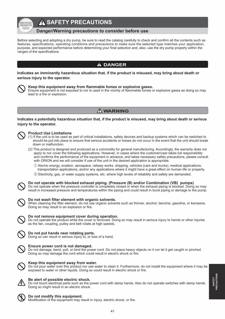
41
Indicates a potentially hazardous situation that, if the product is misused, may bring about death or serious injury to the operator.
Do not operate with blocked exhaust piping. (Pressure (B) and/or Combination (VB) pumps)Do not operate when the pressure controller is completely closed or when the exhaust piping is blocked. Doing so may result in increased pressure and temperatures within the piping and could result in burst piping or damage to the pump.
Do not wash filter element with organic solvents.When cleaning the filter element, do not use organic solvents such as thinner, alcohol, benzine, gasoline, or kerosene. Doing so may result in an explosion or fire.
Do not remove equipment cover during operation.Do not operate the product while the cover is removed. Doing so may result in serious injury to hands or other injuries as the fan, coupling, pulley and belt rotate at high speeds.
Do not put hands near rotating parts.Doing so can result in serious injury to, or loss of a hand.
Ensure power cord is not damaged.Do not damage, bend, pull, or bind the power cord. Do not place heavy objects on it nor let it get caught or pinched. Doing so may damage the cord which could result in electric shock or fire.
Keep this equipment away from water.Do not pour water over this product nor use water to clean it. Furthermore, do not install the equipment where it may be exposed to water or other liquids. Doing so could result in electric shock or fire.
Be alert of possible electric shock.Do not touch electrical parts such as the power cord with damp hands. Also do not operate switches with damp hands. Doing so might result in an electric shock.
Do not modify this equipment.Modification of the equipment may result in injury, electric shock, or fire.
Product Use Limitations(1) If the unit is to be used as part of critical installations, safety devices and backup systems which can be switched to should be put into place to ensure that serious accidents or losses do not occur in the event that the unit should break down or malfunction.(2) This product is designed and produced as a commodity for general manufacturing. Accordingly, the warranty does not apply to nor cover the following applications. However, in cases where the customer/user takes full responsibility and confirms the performance of the equipment in advance, and takes necessary safety precautions, please consult with ORION and we will consider if use of the unit in the desired application is appropriate. ① Atomic energy, aviation, aerospace, railway works, shipping, vehicles (cars and trucks), medical applications, transportation applications, and/or any applications where it might have a great effect on human life or property. ② Electricity, gas, or water supply systems, etc. where high levels of reliability and safety are demanded.
WARNING
SAFE
TYPR
ECA
UTI
ON
S
Keep this equipment away from flammable fumes or explosive gases.Ensure equipment is not exposed to nor is used in the vicinity of flammable fumes or explosive gases as doing so may lead to a fire or explosion.
Indicates an imminently hazardous situation that, if the product is misused, may bring about death or serious injury to the operator.
DANGER
Before selecting and adopting a dry pump, be sure to read the catalog carefully to check and confirm all the contents such as features, specifications, operating conditions and precautions to make sure the selected type matches your application, purpose, and expected performance before determining your final selection and, also, use the dry pump properly within the ranges of the specifications.
Danger/Warning precautions to consider before use
SAFETY PRECAUTIONS

42
Indicates a potentially hazardous situation that, if the product is misused, may bring about death or serious injury to the operator.
Be sure to properly ground the product.Ensure the product is properly grounded from either the grounding screw inside the terminal box or at the lower part of the frame of the motor. Improper or lack of grounding may result in electric shock.
Installation of this product must be done by qualified personnel.If improperly installed, the product may fall down or drop resulting in personal injury, electric shock, or fire.
Do not continue to operate this product if it is not working normally.Stop operation if product does not function normally. Then remove the power cord or shut off the main power supply and consult with your dealer or a qualified repair company. Continued operation of the product when not operating properly can result in electric shock or fire.
Shut off the main power supply before cleaning, maintenance and inspection.Shut off the main power supply before cleaning, maintenance and inspection, and clearly post a sign on the power supply switch to indicate it is under maintenance. Failure to do so may result in electric shock or personal injury. Consult with a specialized company for maintenance and inspection.
Inspect the power plug periodically.If the product is operated with a power plug, periodically inspect the power plug and confirm it is not covered with dust. The power plug must be fully inserted to the root of pins. If the power plug is covered with dust or not fully inserted, it may cause electric shock or fire.
Be sure to install protective devices.Consult with a specialized company to install an earth leakage breaker. Failure to do so may cause electric shock or fire. Also, install an overload protection device (thermal relay). Operation without such devices may cause malfunction due to overload or result in fire.
Always have 2 or more people when installing/moving equipment over 25kg.When installing or moving equipment over 25kg, always lift and move using at least 2 people. And when lifting/moving, do not hold onto the motor control box, filter case, or controller. Dropping equipment may result in injury, damage to the equipment or improper function.
Always use a proper restraining tie-down belt to lift/move equipment over 50kg.When moving equipment over 50kg, always use a tie-down belt to prevent dropping equipment. Not properly securing equipment when moving can lead to injury.
Use eye bolts properly.When using eye bolts, hang the product from 2 points and ensure the cable angle at each point is at least 60 degrees to the base. Failure to handle properly may result in the product overturning or falling down.
Do not use the product outside.The product is intended for indoor operation only. If the product is used outside and is exposed to wind or rain, the motor may suffer damage to the insulation which may result in electric shock or fire.
Make sure caster stoppers are locked.After installation is complete, lock the stoppers on the front casters. Not doing so may lead to the product shifting or falling over which may result in personal injury or damage to the product.
SAFE
TYPR
ECA
UTI
ON
S
Before selecting and adopting a dry pump, be sure to read the catalog carefully to check and confirm all the contents such as features, specifications, operating conditions and precautions to make sure the selected type matches your application, purpose, and expected performance before determining your final selection and, also, use the dry pump properly within the ranges of the specifications.
WARNING
SAFETY PRECAUTIONSDanger/Warning precautions to consider before use

43
Indicates a critical situation that, if the product is misused, may bring about injury to the operator or damage to the product.
Do not operate the product outside the voltage range specified on the motor.Operation with any voltage other than the rated voltage specified for the motor may result in failure or accident.
Do not sit on, lean on, or place objects on the product.Do not place heavy objects or objects containing water on the product. Do not sit or climb on the product. Doing so can result in injuries due to falls. If water spills on the product, rust or damage to insulation may result which could lead to ground leakage or electric shock.
Do not use the product beyond its specified pressure rating.Using the product beyond its specified pressure rating may shorten the life and/or cause damage or failure of the product.
Burn WarningDo not touch areas around the pump, the surface of the after cooler, the exhaust port, or the piping surface on the exhaust side. These surfaces may be hot and cause burns if touched.
Inspect the earth leakage breaker periodically.Periodically check the earth leakage breaker to ensure it is working correctly. Failure of this device may lead to electric shock or a short circuit.
Install check valve.Be sure to install a check valve in a horizontal position within 50cm of the suction (or exhaust port) of the pump in order to avoid reverse-rotation by residual pressure when stopping the pump. Failure to do so may result in injury or malfunc-tion of pump. (Not necessary for KM41A, KYP, KHA, KHH, and KHF.)
Shut off the main power supply when not in use for extended periods.When not used for extended periods, shut off main power supply. Failure to do so may result in electric shock, due to degradation of insulation, or fire due to electrical leakage.
To unplug, do not pull on cable - pull the plug itself.When used with a power plug, remove the plug by grasping the plug and pulling it out. Removing the plug by pulling on the cord may result in partial separation of the core wire which can lead to heat and deterioration.
Ensure wiring does not come into contact with motor frame.Install wiring such that wires do not come into contact with the motor frame otherwise heat from the motor may melt wire insulation or pose a fire risk.
Wear protective gear and clothing when performing cleaning and maintenance.In order to prevent burns, wear gloves when maintaining or cleaning. Not wearing protective gear may result in burns or other injury due to contact with hot motor surfaces.
Wear protective gear and clothing when moving equipment.When moving equipment, wear non-slip gloves and safety-shoes. Not wearing protective clothing while moving equipment may result in injury.
SAFE
TYPR
ECA
UTI
ON
S
CAUTION
Continuous operation is recommended.If start/stop frequencies are high (cycles of 5 minutes or less) the lifetime of the equipment may be significantly reduced or lead to deterioration or malfunction.
Do not wrap gauges or controllers with sealing tape.When installing gauges or controllers, do not apply sealing tape on a threaded part. Doing so may dent, or warp the thread part and may also lead to improper operation.

ESCA stands for "Energy Saving Clean Air"ESCA is ORION's endeavor toward an energy saving environment.ESCA
Energy Saving Proposals
Using an ejector?
What if you could recover wasted compressed air and the wasted electric bill that goes with it?
Recover 60% of your electric costs by using a dry pump.
Energy Savings of
60%Use of Dry Pumps
(Efficient vacuum supply)
Use of Air Ejectors
Ejectors waste energy by using compressed air to generate vacuum.
Weak source of negative-pressure
Large volume of compressed air
Nozzel
Exhaust
Energy Saving ProposalsTo users of Dry Pumps...
Are you wasting energy using your Dry Pump?By not properly replacing filter elements as recommended...
Clogged filters lead to...
Reduced pump power(less vacuum/pressure)
over use of pressure regulator
Increasing pressure or vacuum using pressure regulator
Wasted Electricity Reduced vane and bearing life
10%waste
30%shorter part life
KRF40AKRF40A
Part life(hr)
Current(A
)
Pressure (kPa) Vacuum (kPa)40 4050 5060 6070 7080 80
ESC
AEn
ergy
Sav
ing
Prop
osal
s
44

Oil free vacuum pumps and blowers(Vaneless Pump)
KCP/KCE/KCMseries
KCP/KCE/KCMseries
KCE/KCM SeriesInverter Model / Module Multi Model
※1. eco speed control:Energy saving mechanism that works by automatically adaptingmotor speed to changes in air consumption.
Built-In
※1
"eco2" means Economy (energy savings) and Ecology (environmental protection) and reduced CO2 emissions.
KCE380A[Inverter Model]
KCM620[Module Multi Model]KCE190A
[Inverter Model]
KCP150D[Basic Model]
KCP250[Basic Model]
Ultra ECO Product : Energy Savings of 50% or Better (compared with previous models)

□K No.1073 '14.12.01 pdf SR
This catalogue contains product specifications as of Dec, 2014.●��Actual product colors may vary slightly from catalogue.●��The structure or specifications of products contained in this catalogue are subject to
change without prior notice.
246, Kotaka, Suzaka-shi, Nagano-ken, 382-8502 JapanTEL +81-(0)26-245-1230 FAX +81-(0)26-245-5424 URL: http://www.orionkikai.co.jp
246, Kotaka, Suzaka-shi, Nagano-ken, 382-8502 JapanTEL +81-(0)26-246-5664 FAX +81-(0)26-246-6753 Email: [email protected]
International Group
Head Office & Factory
For Orders and Inquiries:
Products by ORION
SafetyPrecautions
Please read the Operator's Manual thoroughly and operate equipment accordingly.For specialists in installation and wiring of ORION equipment, please consult your ORION dealer.Choose the ORION product that best suits your needs. Please do not use any equipment in a manner for which it was not intended. Doing so may lead to equipment damage or failure.
Continually developing a complete and trustworthy nation-wide network of expedient sales and service everywhere, anytime.
ISO 14001認証番号00008-1
ORION Machinery Co., Ltd is an ISO Certified, Quality Management and Environmental
Management company.
What is ISO certification system?ISO (International Organization for Standardization) is an established body that stipulates and certifies ISO9001 and ISO14001 directives. ISO9001 stipulates a system of Quality Management that ensures customer satisfaction and trust in a company's products and services it provides. ISO14001 stipulates a system of Environmental Management whereby production and business activities are carried out in an environmentally conscious manner.
Dairy Equipment
Photo:Milking Unit Automated Transportation Equipment Carry Robo UCA30A
Products■�Milking equipment■�Refrigerating equipment■�Feeding equipment■�Animal waste treatment equipment
Vacuum Pumps and Related Equipment
Products■��Dry Pump (Oil-less rotary vane vacuum pump)■� Silent Box (Dry pump soundproofing enclosure)■�Clean Filter
Photo : Dry Pump KRFSeries
Heating Equipment
Products■��Jet Heater BRITE (Infrared heater)■��Jet Heater HP (Portable warm air heater)■� Jet Heater HS (Convection warm air heater)
Photo : Jet Heater BRITE HRR480A-S
Refrigerating Equipment
Photo : DC Inverter Chiller RKE3750B-V
Products■�Inverter Chiller■�Unit Cooler (Fluid circulation refrigeration unit)■�Dehumidifier■�Food Processing and Preserving Equipment■�Others
Compressed Air Equipment
Products■�Air Dryer (Refrigerated compressed air dryer)■��Heatless Air Dryer (Adsorption type compressed air dryer)■��Air Filter (Compressed air purification equipment)■�Others
Precision Air Processor
Products■�� Precision Air Processor■�� Percision Water Chiller
(Precision control of water temperature)
■���In-Line Type Temperature Inspection Equipment
■�� Thermal Fresh (Precision control of temperature and humidity)
■�OthersPhoto : Precision Air Processor
PAP10A1-K
Photo : DC Inverter Air DryerRAXE1100B-SE
Top Related