


Languages
Pages
Legal

May 2021 2
VDM® Alloy 2120 MoN is a nickel-chromium-molybdenum alloy with particularly low carbon content and an addition of
nitrogen, developed by VDM Metals. The material distinguishes itself through an outstanding corrosion resistance under
reducing as well as under oxidizing conditions. Furthermore, VDM® Alloy 2120 MoN is characterized by superior strength
compared to other C alloys.
VDM® Alloy 2120 MoN is characterized by:
extraordinary resistance against pitting and crevice corrosion as well as against chlorine induced stress corrosion
cracking
excellent resistance against a huge number of corrosive media, beginning with strong reducing conditions right
up to oxidizing conditions
excellent resistance against mineral acids like sulfuric acid, hydrochloric acid
good ductility
good weldability
intended application area of -196 to 450 °C (-320 to 842 °F)
approval for pressure vessels according to ASME Code Section VIII Div 1; Section VIII Div 2, Class 1 applica-tions.
Designation
Standard Material Designation
EN 2.4700
UNS N06058
Standards
Product form ASTM VdTÜV Others
Strip B 575 586 ASME Code-Case 2983*
Rod and bar B 574 ASME Code-Case 2983*
Sheet and plate B 575 586 ASME Code-Case 2983*
Tube and pipe
welded
B 619
B 626
ASME Code-Case 2983*
Forging B 564 ASME Code-Case 2983*
*Solution annealed variation
Table 1 – Designations and standards
Nicrofer 5821 hMoN
May 2021 3
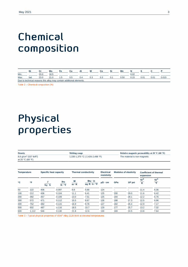
Ni Cr Mo Fe Cu Al W Co Si Mn N S C P
Min. 20.0 18.5 0.02
Max. bal. 23.0 21.0 1.5 0.5 0.4 0.3 0.3 0.1 0.50 0.15 0.01 0.01 0.015
Due to technical reasons this alloy may contain additional elements.
Table 2 – Chemical composition (%)
Density Melting range Relative magnetic permeability at 20 °C (68 °F)
8,6 g/cm3 (537 lb/ft3)
at 20 °C (68 °F)
1,330-1,370 °C ( 2,426-2,498 °F) The material is non-magnetic
Temperature Specific heat capacity Thermal conductivity Electrical
resistivity
Modulus of elasticity Coefficient of thermal
expansion
°C
°F
J
Kg · K
Btu
lb ∙ °F
W
m ∙ K
Btu ∙ in
sq. ft ∙ h ∙ °F
μΩ · cm
GPa
106 psi 10
-6
K
10-6
°F
50 122 406 0.097 9.8 5.66 124 - - 11.4 6.36
100 212 436 0.104 11.1 6.41 125 200 29.0 11.6 6.42
200 392 457 0.109 13.0 7.51 125 194 28.1 12.2 6.76
300 572 471 0.112 15.5 8.67 126 188 27.3 12.5 6.96
400 752 482 0.115 16.9 9.76 127 182 26.4 12.9 7.17
500 932 487 o.116 18.5 10.7 129 177 25.7 13.2 7.32
600 1,112 546 0.130 21.8 12.6 130 169 24.5 13.8 7.64
Table 3 – Typical physical properties of VDM® Alloy 2120 MoN at elevated temperatures
May 2021 4
VDM® Alloy 2120 MoN has a face-centered cubic structure. In the temperature range from 600 to 1,140 °C (1,112 to 2,084
°F), inter-metallic phases may form in the event of longer exposure times or too slow cooling down. In addition, carbides
can precipitate on the grain boundaries, which reduce resistance against inter-crystalline corrosion.
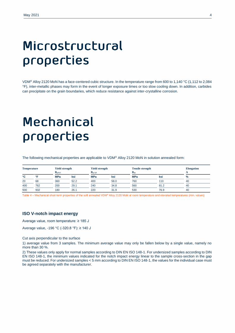
The following mechanical properties are applicable to VDM® Alloy 2120 MoN in solution annealed form:
Temperature Yield strength
Rp 0.2
Yield strength
Rp 1,0
Tensile strength
Rm
Elongation
A
°C °F MPa ksi MPa ksi MPa ksi %
20 68 360 52.2 400 58.0 760 110 40
400 762 200 29.1 240 34.8 560 81.2 40
500 932 180 26.1 220 31.9 530 76.9 40
Table 4 – Mechanical short-term properties of the soft annealed VDM® Alloy 2120 MoN at room temperature and elevated temperatures (min. values)
ISO V-notch impact energy
Average value, room temperature: ≥ 185 J
Average value, -196 °C (-320.8 °F): ≥ 140 J
Cut axis perpendicular to the surface
1) average value from 3 samples. The minimum average value may only be fallen below by a single value, namely no more than 30 %.
2) These values only apply for normal samples according to DIN EN ISO 148-1. For undersized samples according to DIN EN ISO 148-1, the minimum values indicated for the notch impact energy linear to the sample cross-section in the gap must be reduced. For undersized samples < 5 mm according to DIN EN ISO 148-1, the values for the individual case must be agreed separately with the manufacturer.
May 2021 5
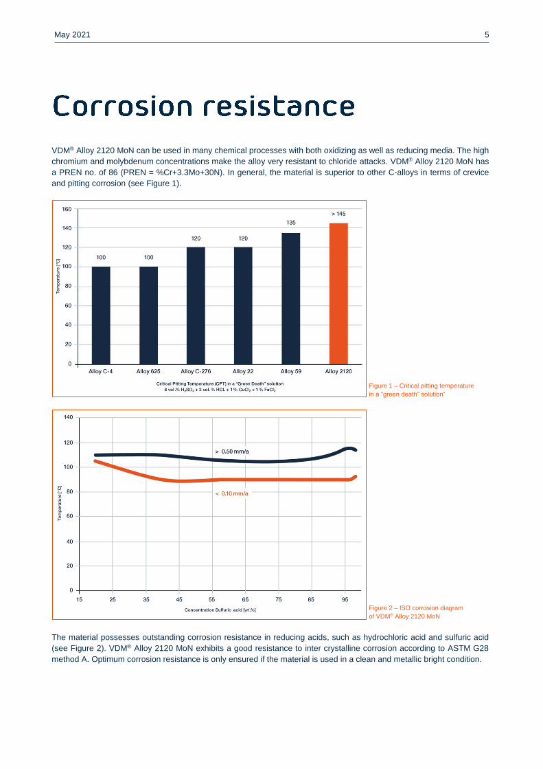
VDM® Alloy 2120 MoN can be used in many chemical processes with both oxidizing as well as reducing media. The high
chromium and molybdenum concentrations make the alloy very resistant to chloride attacks. VDM® Alloy 2120 MoN has
a PREN no. of 86 (PREN = %Cr+3.3Mo+30N). In general, the material is superior to other C-alloys in terms of crevice
and pitting corrosion (see Figure 1).
Figure 1 – Critical pitting temperature
in a “green death” solution“
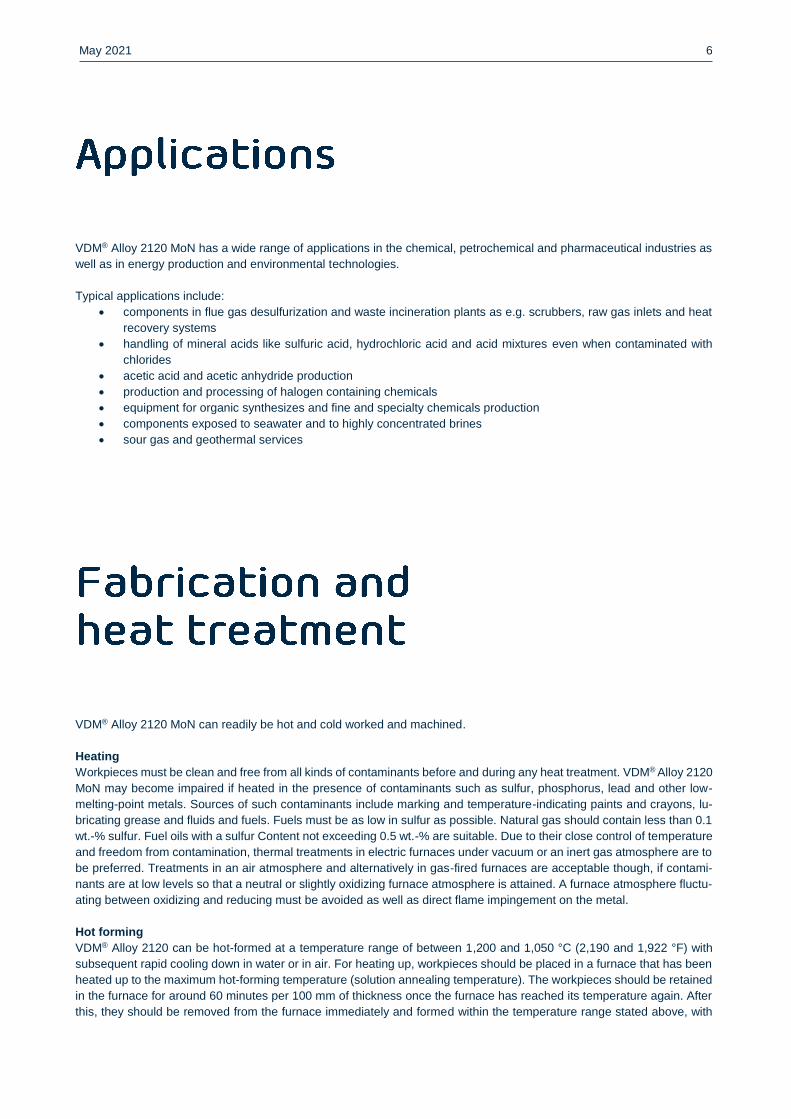
Figure 2 – ISO corrosion diagram
of VDM® Alloy 2120 MoN
The material possesses outstanding corrosion resistance in reducing acids, such as hydrochloric acid and sulfuric acid
(see Figure 2). VDM® Alloy 2120 MoN exhibits a good resistance to inter crystalline corrosion according to ASTM G28
method A. Optimum corrosion resistance is only ensured if the material is used in a clean and metallic bright condition.
May 2021 6
VDM® Alloy 2120 MoN has a wide range of applications in the chemical, petrochemical and pharmaceutical industries as
well as in energy production and environmental technologies.
Typical applications include:
components in flue gas desulfurization and waste incineration plants as e.g. scrubbers, raw gas inlets and heat
recovery systems
handling of mineral acids like sulfuric acid, hydrochloric acid and acid mixtures even when contaminated with
chlorides
acetic acid and acetic anhydride production
production and processing of halogen containing chemicals
equipment for organic synthesizes and fine and specialty chemicals production
components exposed to seawater and to highly concentrated brines
sour gas and geothermal services
VDM® Alloy 2120 MoN can readily be hot and cold worked and machined.
Heating
Workpieces must be clean and free from all kinds of contaminants before and during any heat treatment. VDM® Alloy 2120
MoN may become impaired if heated in the presence of contaminants such as sulfur, phosphorus, lead and other low-
melting-point metals. Sources of such contaminants include marking and temperature-indicating paints and crayons, lu-
bricating grease and fluids and fuels. Fuels must be as low in sulfur as possible. Natural gas should contain less than 0.1
wt.-% sulfur. Fuel oils with a sulfur Content not exceeding 0.5 wt.-% are suitable. Due to their close control of temperature
and freedom from contamination, thermal treatments in electric furnaces under vacuum or an inert gas atmosphere are to
be preferred. Treatments in an air atmosphere and alternatively in gas-fired furnaces are acceptable though, if contami-
nants are at low levels so that a neutral or slightly oxidizing furnace atmosphere is attained. A furnace atmosphere fluctu-
ating between oxidizing and reducing must be avoided as well as direct flame impingement on the metal.
Hot forming
VDM® Alloy 2120 can be hot-formed at a temperature range of between 1,200 and 1,050 °C (2,190 and 1,922 °F) with
subsequent rapid cooling down in water or in air. For heating up, workpieces should be placed in a furnace that has been
heated up to the maximum hot-forming temperature (solution annealing temperature). The workpieces should be retained
in the furnace for around 60 minutes per 100 mm of thickness once the furnace has reached its temperature again. After
this, they should be removed from the furnace immediately and formed within the temperature range stated above, with
May 2021 7
reheating necessary once the temperature reaches 1,050 °C (1,922 °F). Solution annealing after hot forming is recom-
mended for the achievement of optimal properties and maximum corrosion resistance.
Cold forming
For cold forming the material should be in the annealed condition. VDM® Alloy 2120 MoN has a higher work-hardening
rather than austenitic stainless steels. This should be taken into account when selecting forming equipment. Interstage
annealing may be necessary with high degrees of cold forming. After cold working with more than 15% deformation solu-
tion annealing is required before use.
Heat treatment
Solution annealing should take place at temperatures of between 1,150 and 1,185 °C (2,102 – 2,156 °F) to achieve optimal
properties. The retention time during annealing depends on the semi-finished product thickness and can be calculated as
follows:
For thicknesses d ≤ 10 mm (0.4 in), the retention time is t = d • 3 min/mm
For thicknesses d = 10 to 20 mm (0.4 to 0.8 in), the retention time is t = 30 min + (d - 10 mm) • 2 min/mm
For thicknesses of d > 20 mm (0.8 in), the retention time is t = 50 min + (d - 20 mm) • 1 min/mm
The retention time commences with material temperature equalization; longer times are generally considerably less critical
than retention times that are too short. For maximum corrosion resistance, the workpieces must be quickly cooled from
the annealing temperature of at least 1,100 to 500 °C (2,012 to 932 °F) with a cooling rate of >150 °C/min (302 °F). The
material must be placed in a furnace that has been heated up to the maximum annealing temperature before any heat
treatment. For strip and wire products, the heat treatment can be performed in a continuous furnace at a speed and
temperature that is adapted to the material thickness. The cleanliness requirements listed under "Heating" must be ob-
served.
Descaling and pickling
Oxides of VDM® Alloy 2120 MoN and discoloration adjacent to welds are more adherent than on stainless steels. Grinding
with very fine abrasive belts or discs is recommended. Care should be taken to prevent tarnishing. Before pickling which
may be performed in a nitric/hydrofluoric acid mixture with proper control of pickling time and temperature, the surface
oxide layer must be broken up by abrasive blasting, by carefully performed grinding or by pretreatment in a fused salt
bath.
Machining
Machining of VDM® Alloy 2120 should take place in an annealed condition. Because of the considerably elevated tendency
toward work hardening in comparison with low-alloy austenitic stainless steels, a low cutting speed and a feed level that
is not too high should be selected and the cutting tool should be engaged at all times. An adequate chip depth is important
in order to cut below the previously formed strain-hardened zone. Optimum heat dissipation through the use of large
quantities of suitable, preferably aqueous, lubricants has considerable influence on a stable machining process.
May 2021 8
When welding nickel alloys and special stainless steels, the following information should be taken into account:
Safety
The safety recommendations of the manufacturer of welding consumables have to be taken into consideration especially
to avoid dust and smoke exposure.
Workplace
A workplace, which is specifically separated from areas in which C-steel is being processed, must be provided. Maximum
cleanliness is required, and drafts should be avoided during gas-shielded welding.
Auxiliary equipment and clothing
Clean fine leather gloves and clean working clothes must be used.
Tools and machines
Tools that have been used for other materials may not be used for nickel alloys and stainless steels. Only stainless steel
brushes may be used. Machines such as shears, punches or rollers must be fitted (e.g. with felt, cardboard, films) so that
the workpiece surfaces cannot be damaged by such equipment due to pressed-in iron particles as this can lead to corro-
sion.
Edge preparation
Welding edge preparation should preferably be carried out using mechanical methods such as lathing, milling or planing.
Abrasive waterjet cutting or plasma cutting is also possible. In the latter case, however, the cut edge (seam flank) must
be cleanly reworked. Careful grinding without overheating is also permissible.
Striking the arc
Striking may only take place in the seam area, such as on the weld edges or on an outlet piece, and not on the component
surface. Striking points are places that may be more susceptible to corrosion.
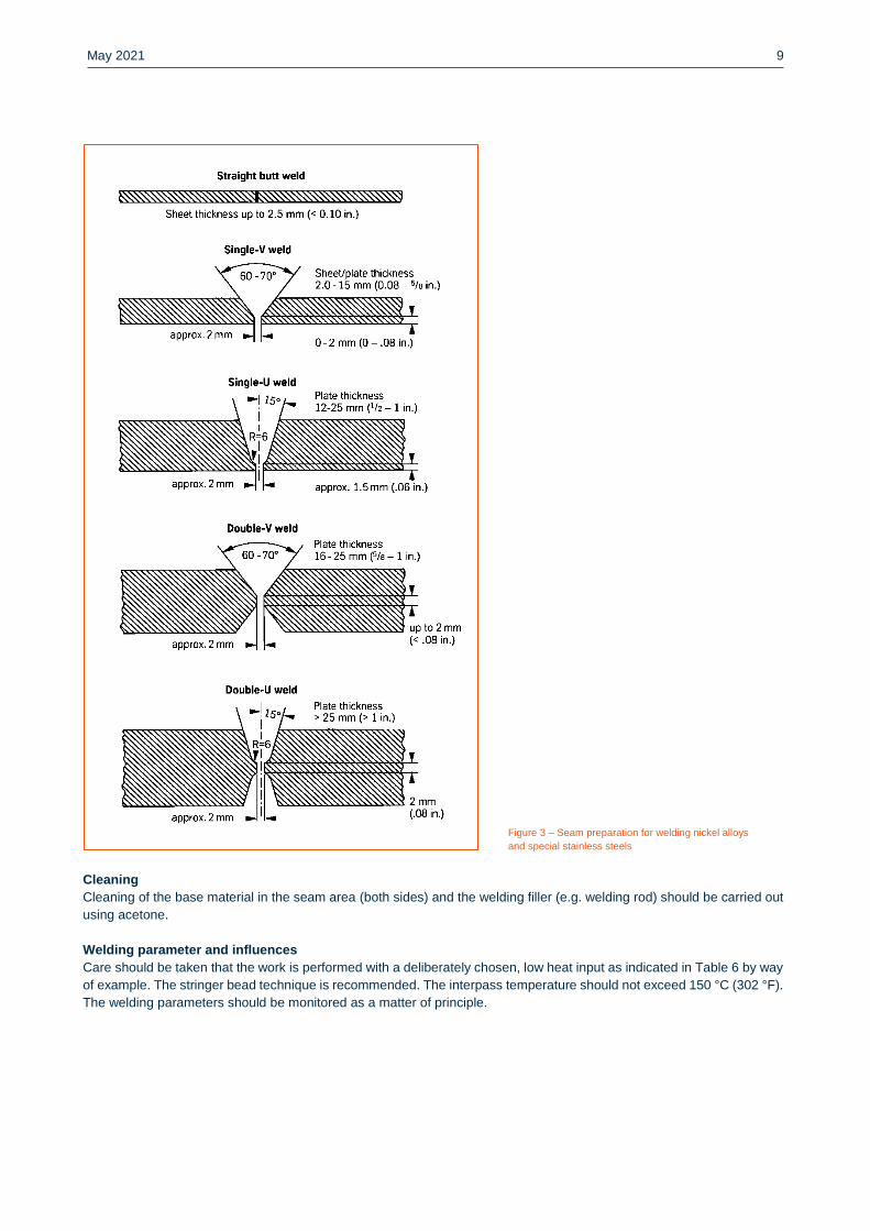
Included angle
Compared to C-steels, nickel alloys and special stainless steels exhibit lower heat conductivity and greater heat expan-
sion. Larger root gaps and web spacing (1 to 3 mm/ 0,039 to 0,118 in) are required to live up to these properties. Due to
the viscosity of the welding material (compared to standard austenitic steels) and the tendency to shrink, opening angles
of 60 to 70° – as shown in Figure 3 – have to be provided for butt welds.
May 2021 9
Figure 3 – Seam preparation for welding nickel alloys
and special stainless steels
Cleaning
Cleaning of the base material in the seam area (both sides) and the welding filler (e.g. welding rod) should be carried out
using acetone.
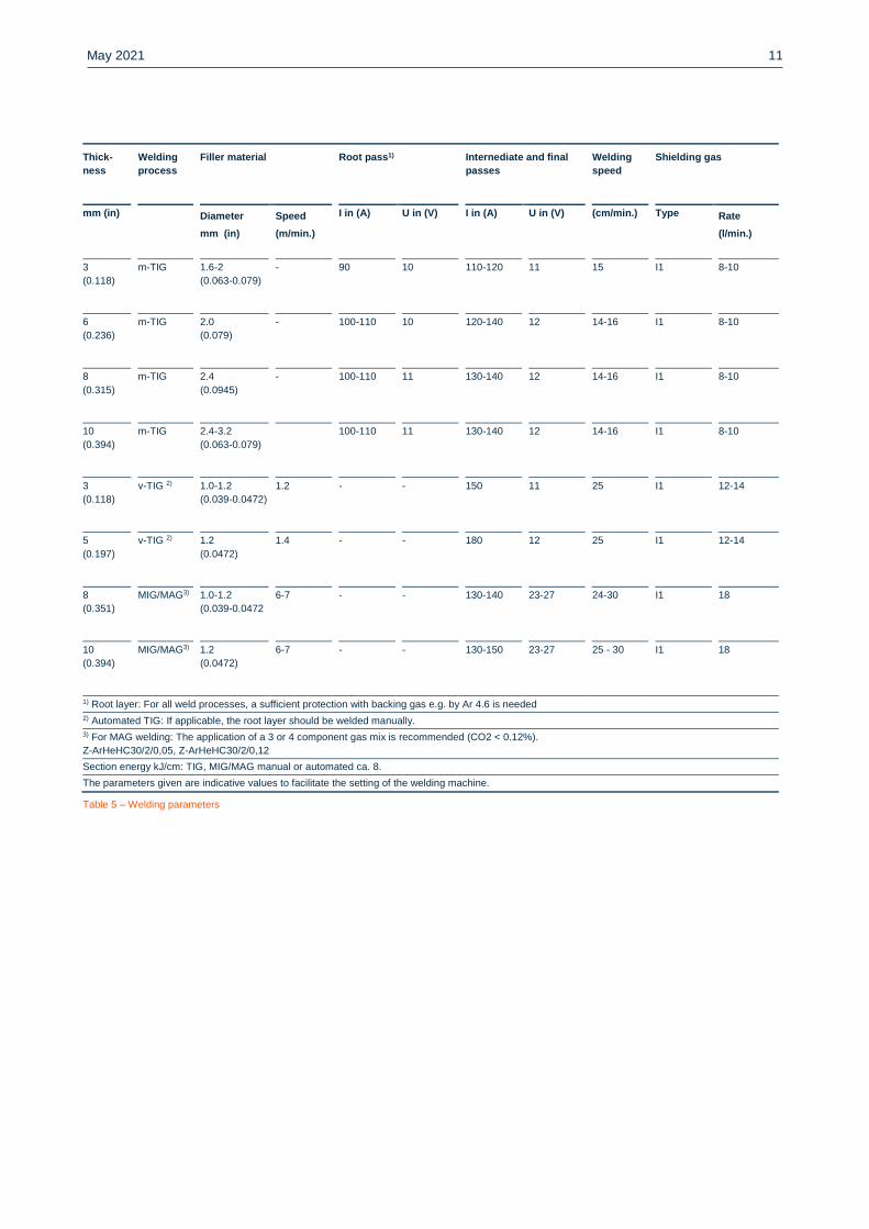
Welding parameter and influences
Care should be taken that the work is performed with a deliberately chosen, low heat input as indicated in Table 6 by way
of example. The stringer bead technique is recommended. The interpass temperature should not exceed 150 °C (302 °F).
The welding parameters should be monitored as a matter of principle.
May 2021 10
The heat input Q can be calculated as follows:
Q = U · I · 60
v · 1.000 (
kJ
cm)
U = arc voltage, volts
I = welding current strength, amperes
v = welding speed, cm/minute
Post- treatment (brushing, pickling and thermal treatments)
Brushing with a stainless steel wire brush immediately after welding, i.e. while the metal is still warm generally results in
removal of heat tint and produces the desired surface condition without additional pickling.
Pickling, if required or pre-scribed, however, would generally be the last operation performed on the weldment. Please
also refer to the information on ‘Descaling and pickling. Neither pre- nor post weld heat treatments are normally required.
Following filler metals are recommended
VDM® FM 2120
ISO 18274 - S Ni 6058 (NiCr21Mo20),
AWS 5.14 Classification ERNiCrMo-19 (UNS N06058)
as TIG rods, weld wire, wire electrode
(TÜV data sheet No. 18953, 18954, 18965)
May 2021 11
Thick-
ness
Welding
process
Filler material Root pass1) Internediate and final
passes
Welding
speed
Shielding gas
mm (in) Diameter
mm (in)
Speed
(m/min.)
I in (A) U in (V) I in (A) U in (V) (cm/min.) Type Rate
(l/min.)
3
(0.118)
m-TIG 1.6-2
(0.063-0.079)
- 90 10 110-120 11 15 I1 8-10
6
(0.236)
m-TIG 2.0
(0.079) - 100-110 10 120-140 12 14-16 I1 8-10
8
(0.315)
m-TIG 2.4
(0.0945)
- 100-110 11 130-140 12 14-16 I1 8-10
10
(0.394)
m-TIG 2.4-3.2
(0.063-0.079)
100-110 11 130-140 12 14-16 I1 8-10
3
(0.118)
v-TIG 2) 1.0-1.2
(0.039-0.0472)
1.2 - - 150 11 25 I1 12-14
5
(0.197)
v-TIG 2) 1.2
(0.0472)
1.4 - - 180 12 25 I1 12-14
8
(0.351)
MIG/MAG3) 1.0-1.2
(0.039-0.0472 6-7 - - 130-140 23-27 24-30 I1
18
10
(0.394) MIG/MAG3) 1.2
(0.0472)
6-7 - - 130-150 23-27 25 - 30 I1 18
1) Root layer: For all weld processes, a sufficient protection with backing gas e.g. by Ar 4.6 is needed
2) Automated TIG: If applicable, the root layer should be welded manually.
3) For MAG welding: The application of a 3 or 4 component gas mix is recommended (CO2 < 0.12%).
Z-ArHeHC30/2/0,05, Z-ArHeHC30/2/0,12
Section energy kJ/cm: TIG, MIG/MAG manual or automated ca. 8.
The parameters given are indicative values to facilitate the setting of the welding machine.
Table 5 – Welding parameters
May 2021 12
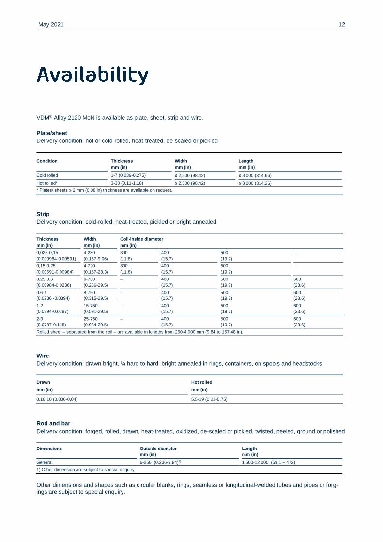
VDM® Alloy 2120 MoN is available as plate, sheet, strip and wire.
Plate/sheet
Delivery condition: hot or cold-rolled, heat-treated, de-scaled or pickled
Condition Thickness
mm (in)
Width
mm (in)
Length
mm (in)
Cold rolled 1-7 (0.039-0.275) ≤ 2,500 (98.42) ≤ 8,000 (314.96)
Hot rolled* 3-30 (0.11-1.18) ≤ 2,500 (98.42) ≤ 8,000 (314.26)
* Plates/ sheets ≤ 2 mm (0.08 in) thickness are available on request.
Strip
Delivery condition: cold-rolled, heat-treated, pickled or bright annealed
Thickness
mm (in)
Width
mm (in)
Coil-inside diameter
mm (in)
0,025-0,15
(0.000984-0.00591)
4-230
(0.157-9.06)
300
(11.8)
400
(15.7)
500
(19.7)
–
0,15-0,25
(0.00591-0.00984)
4-720
(0.157-28.3)
300
(11.8)
400
(15.7)
500
(19.7)
–
0,25-0,6
(0.00984-0.0236)
6-750
(0.236-29.5)
– 400
(15.7)
500
(19.7)
600
(23.6)
0,6-1
(0.0236 -0.0394)
8-750
(0.315-29.5)
– 400
(15.7)
500
(19.7)
600
(23.6)
1-2
(0.0394-0.0787)
15-750
(0.591-29.5)
– 400
(15.7)
500
(19.7)
600
(23.6)
2-3
(0.0787-0.118)
25-750
(0.984-29.5)
– 400
(15.7)
500
(19.7)
600
(23.6)
Rolled sheet – separated from the coil – are available in lengths from 250-4,000 mm (9.84 to 157.48 in).
Wire
Delivery condition: drawn bright, ¼ hard to hard, bright annealed in rings, containers, on spools and headstocks
Drawn
mm (in)
Hot rolled
mm (in)
0.16-10 (0.006-0.04) 5.5-19 (0.22-0.75)
Rod and bar
Delivery condition: forged, rolled, drawn, heat-treated, oxidized, de-scaled or pickled, twisted, peeled, ground or polished
Dimensions Outside diameter
mm (in)
Length
mm (in)
General 6-250 (0.236-9.84)1) 1,500-12,000 (59.1 – 472)
1) Other dimension are subject to special enquiry
Other dimensions and shapes such as circular blanks, rings, seamless or longitudinal-welded tubes and pipes or forg-ings are subject to special enquiry.
May 2021 13
H. Alves; R. Behrens; D. Kurumlu; R. Bäßler: High Performance Alloys to mitigate Corrosion in the Energy Industry – A Contribution to a clean Environment, Eurocorr 2013, Estoril Portugal H. Alves; D. Kurumlu; R. Behrens: A New Developed Ni-Cr-Mo Alloy with Improved Corrosion Resistance in Flue Gas Desulfurization and Chemical Process Applications, Corrosion 2013, Paper N° 2325, NACE international, Orlando, Flor-ida 2013 H. Alves; R. Behrens; L. Paul: Evolution of Nickel Base Alloys – Modification to Traditional Alloy for Specific Applica-tions, Corrosion 2014, Paper N° 4317, NACE international, Houston, Texas 2014 H. Alves; R. Behrens; L. Paul: Recent Experiences and Applications with a New Ni-Cr-Mo-N Alloy, Corrosion 2015, Pa-per N° 5683, NACE international, Dallas Texas 2015
May 2021 14
06 May 2021
Publisher
VDM Metals International GmbH
Plettenberger Straße 2
58791 Werdohl
Germany
Disclaimer
All information contained in this data sheet is based on the results of research and development work carried out by VDM
Metals International GmbH and the data contained in the specifications and standards listed available at the time of print-
ing. The information does not represent a guarantee of specific properties. VDM Metals reserves the right to change
information without notice. All information contained in this data sheet is compiled to the best of our knowledge and is
provided without liability. Deliveries and services are subject exclusively to the relevant contractual conditions and the
General Terms and Conditions issued by VDM Metals. Use of the most up-to-date version of this data sheet is the re-
sponsibility of the customer.
VDM Metals International GmbH
Plettenberger Straße 2
58791 Werdohl
Germany
Telefon +49 (0)2392 55 0
Fax +49 (0)2392 55 22 17
www.vdm-metals.com
Top Related