


Languages
Pages
Legal


Spacecraft StructuresSpace System Design, MAE 342, Princeton University
Robert Stengel
Copyright 2008 by Robert Stengel. All rights reserved. For educational use only.http://www.princeton.edu/~stengel/MAE342.html
• Discrete (lumped-mass)structures
• Distributed structures
• Buckling
• Structural dynamics
• Finite-element analysis
Spacecraft Mounting
for Launch
• Spacecraft protected fromatmospheric heating andloads by fairing
• Fairing jettisoned whenatmospheric effects becomenegligible
• Spacecraft attached torocket by adapter, whichtransfers loads between thetwo
• Spacecraft (usually)separated from rocket atcompletion of thrusting
• Clamps and springs forattachment and separation
Fairing Constraints for
Various Launch Vehicles
• Static envelope
• Dynamic envelope accountsfor launch vibrations, withsufficient margin for error
• Various appendages stowedfor launch
• Large variation inspacecraft inertialproperties whenappendages are deployed
STEREO Spacecraft Primary
Structure Configuration
• Spacecraft structuretypically consists of
– Beams
– Flat and cylindrical panels
– Cylinders and boxes
• Primary structure is the“rigid” skeleton of thespacecraft
• Secondary structure maybridge the primary structureto hold components
Solar TErrestrial RElations Observatory

UARS Primary and
Secondary Structure
• Instrument Module provides
– Support for 10 scientificinstruments
– Maintains instrumentalignment boresights
– Interfaces to launch vehicle(SSV)
• Secondary Structuresupports
– 6 equipment benches
– 1 optical bench
– Instrument mounting links
– Solar array truss
– Several instruments havekinematic mounts
Structural Material Properties
• Stress, !: Force per unit area
• Strain, ": Elongation per unit length
!
" = E #
• Proportionality factor, E: Modulus of elasticity, or Young!s modulus
• Strain deformation is reversible below the elastic limit
• Elastic limit = yield strength
• Proportional limit ill-defined for many materials
• Ultimate stress: Material breaks
• Poisson!s ratio, #:
!
" =#lateral
#axial,
typically 0.1 to 0.35
• Thickening under compression
• Thinning under tension
Uniform Stress Conditions
• Average axial stress, !
!
" = P A = Load Cross Sectional Area
• Average axial strain, "
!
" = #L L
• Effective spring constant, ks
!
" = P A = E# = E$L
L
P =AE
L$L = k
s$L
Springs and Dampers
!
fx = "ks#x = "ks x " xo( ) ; k = springconstant
!
fx = "kd#˙ x = "kd#v = "kd v " vo( ) ; k = dampingconstant
• Force due to linear spring
• Force due to linear damper
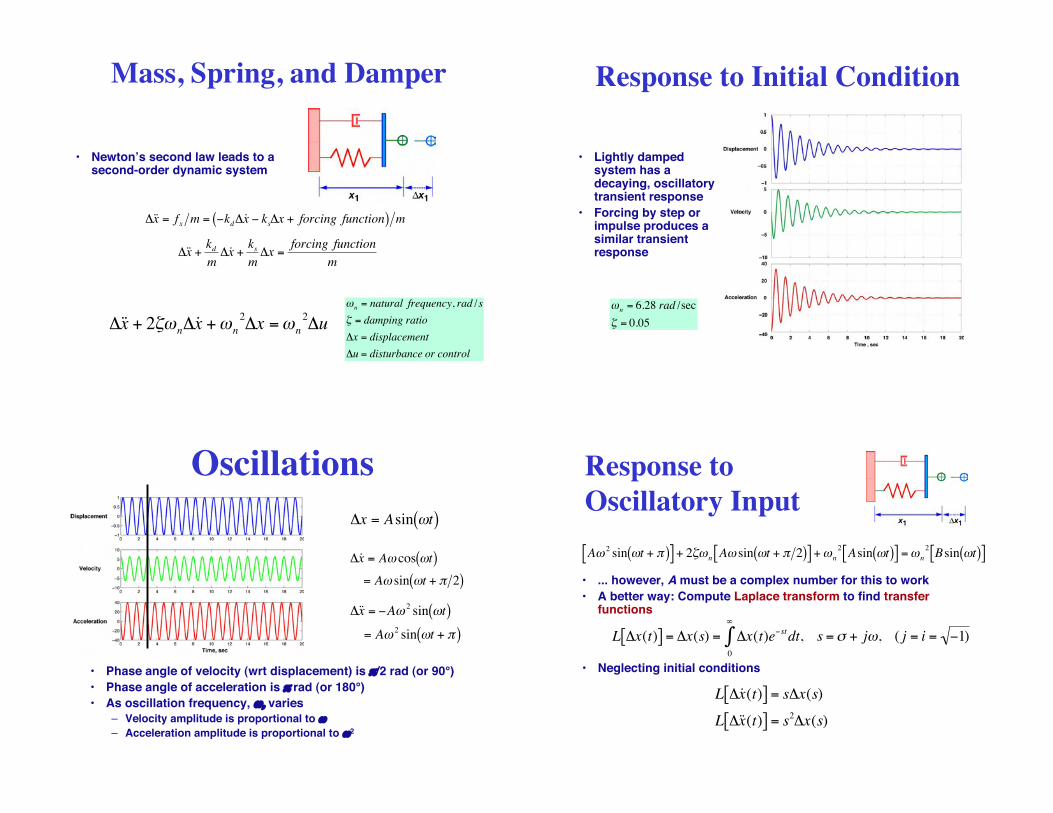
Mass, Spring, and Damper
!
"˙ ̇ x = fx m = #kd"˙ x # ks"x + forcing function( ) m
!
"˙ ̇ x +kd
m"˙ x +
ks
m"x =
forcing function
m
!
"˙ ̇ x + 2#$n"˙ x +$
n
2
"x =$n
2
"u
!
"n = natural frequency, rad /s
# = damping ratio
$x = displacement
$u = disturbance or control
• Newton!s second law leads to asecond-order dynamic system
Response to Initial Condition
• Lightly dampedsystem has adecaying, oscillatorytransient response
• Forcing by step orimpulse produces asimilar transientresponse
!
"n
= 6.28 rad /sec
# = 0.05
Oscillations
!
"x = Asin #t( )
!
"˙ x = A# cos #t( )
= A# sin #t + $ 2( )
!
"˙ ̇ x = #A$ 2sin $t( )
= A$ 2sin $t + %( )
• Phase angle of velocity (wrt displacement) is $/2 rad (or 90°)
• Phase angle of acceleration is $ rad (or 180°)
• As oscillation frequency, %, varies
– Velocity amplitude is proportional to %
– Acceleration amplitude is proportional to %2
Response to
Oscillatory Input
!
A" 2sin "t + #( )[ ] + 2$"
nA" sin "t + # 2( )[ ] +"
n
2
Asin "t( )[ ] ="n
2
Bsin "t( )[ ]
• ... however, A must be a complex number for this to work
• A better way: Compute Laplace transform to find transferfunctions
!
L "x(t)[ ] = "x(s) = "x(t)e#stdt0
$
% , s =& + j', ( j = i = #1)
!
L "˙ x (t)[ ] = s"x(s)
L "˙ ̇ x (t)[ ] = s2"x(s)
• Neglecting initial conditions
Transfer Function
• or
!
L "˙ ̇ x + 2#$n"˙ x +$
n
2
"x( ) = L $n
2
"u( )
!
s2 + 2"#
ns+#
n
2( )$x(s) =#n
2$u(s)
• Transfer function from input to displacement
!
"x(s)
"u(s)=
#n
2
s2 + 2$#
ns+#
n
2( )
Transfer Functions of Displacement,
Velocity, and Acceleration
!
"x(s)
"u(s)=
#n
2
s2 + 2$#
ns +#
n
2( )"˙ x (s)
"u(s)=
#n
2s
s2 + 2$#
ns +#
n
2( )"˙ ̇ x (s)
"u(s)=
#n
2s
2
s2 + 2$#
ns +#
n
2( )
• Input tovelocity:multiply by s
• Input toacceleration:multiply by s2
• Transfer functionfrom input todisplacement
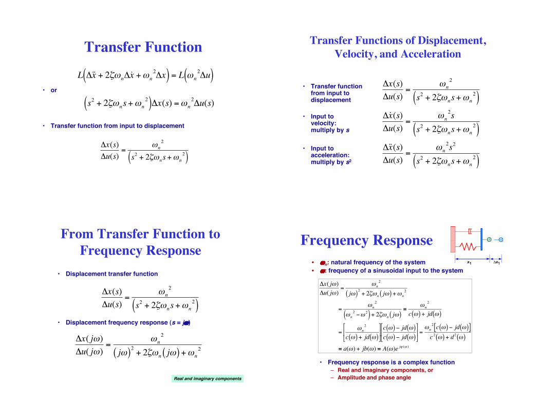
From Transfer Function to
Frequency Response
• Displacement frequency response (s = j%)
!
"x( j#)
"u( j#)=
#n
2
j#( )2
+ 2$#n j#( ) +#n
2!
"x(s)
"u(s)=
#n
2
s2 + 2$#
ns+#
n
2( )
• Displacement transfer function
Real and imaginary components
Frequency Response
• %n: natural frequency of the system
• %: frequency of a sinusoidal input to the system
!
"x( j#)
"u( j#)=
#n
2
j#( )2
+ 2$#n j#( ) +#n
2
=#n
2
#n
2 %# 2( ) + 2$#n j#( )&
#n
2
c #( ) + jd #( )
=#n
2
c #( ) + jd #( )
'
( )
*
+ , c #( ) % jd #( )c #( ) % jd #( )
'
( )
*
+ , =
#n
2c #( ) % jd #( )[ ]
c2 #( ) + d2 #( )
& a(#) + jb(#) & A(#)e j- (# )
• Frequency response is a complex function
– Real and imaginary components, or
– Amplitude and phase angle
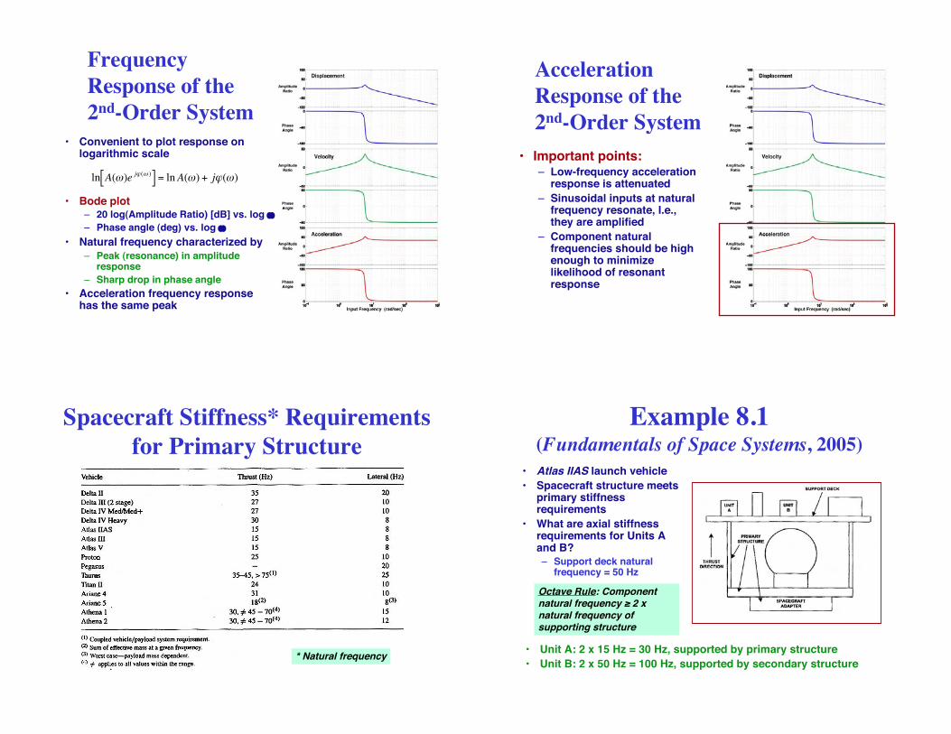
Frequency
Response of the
2nd-Order System
• Bode plot– 20 log(Amplitude Ratio) [dB] vs. log !
– Phase angle (deg) vs. log !
• Natural frequency characterized by
– Peak (resonance) in amplituderesponse
– Sharp drop in phase angle
• Acceleration frequency responsehas the same peak
• Convenient to plot response onlogarithmic scale
!
ln A(")e j# (" )[ ] = lnA(") + j#(")
Acceleration
Response of the
2nd-Order System
• Important points:– Low-frequency acceleration
response is attenuated
– Sinusoidal inputs at naturalfrequency resonate, I.e.,they are amplified
– Component naturalfrequencies should be highenough to minimizelikelihood of resonantresponse
Spacecraft Stiffness* Requirements
for Primary Structure
* Natural frequency
Example 8.1(Fundamentals of Space Systems, 2005)
• Atlas IIAS launch vehicle
• Spacecraft structure meetsprimary stiffnessrequirements
• What are axial stiffnessrequirements for Units Aand B?
– Support deck naturalfrequency = 50 Hz
Octave Rule: Componentnatural frequency ! 2 xnatural frequency ofsupporting structure
• Unit A: 2 x 15 Hz = 30 Hz, supported by primary structure
• Unit B: 2 x 50 Hz = 100 Hz, supported by secondary structure

Factors and Margins of Safety
• Factor of Safety– Typical values: 1.25 to 1.4
!
Allowable load (yield stress)
Expected limit load (stress) "Design factor of safety#1
• Margin of Safety– “the amount of margin that exists above the
material allowables for the applied loadingcondition (with the factor of safety included)”,Skullney, Ch. 8, Pisacane, 2005
!
Load (stress) that causes yield or failure
Expected service load
Worst-Case Axial Stress
on a Simple Beam
• Axial stress due to bending
!
" = My I
!
" =M h /2( )
I
• Maximum stress
• Worst-case axial stress due to bending and axial force
!
"wc
= ±P
A
#
$ %
&
' ( max
±M h /2( )
I
Example 8.3(Fundamentals of Space Systems, 2005)
• Spacecraft weight = 500 lb
• Atlas IIAS launch vehicle
• Factor of safety = 1.25
• Maximum stress onspacecraft adapter?
Atlas IIAS Limit Loads (g)
Example 8.3, con’t.
• Worst-case axial load at BECO (5±0.5 g)
!
"wc
= ±P
A
#
$ %
&
' ( max
±Mc
I
!
A = 2"rt = 7.1 in2
I = "r3t = 286 in4
• Worst-case stress
!
"wc =500 # 5.5
7.1+500 # 0.5 # 42 # 9
286
$
% & '
( ) #1.25 = 897.1 psi
• Worst-case lateral load at BECO (2.5 ± 1 g) or Maximum FlightWinds (2.7 ± 0.8 g)
!
"wc =500 # 3.5
7.1+500 # 2 # 42 # 9
286
$
% & '
( ) #1.25 =1960 psi
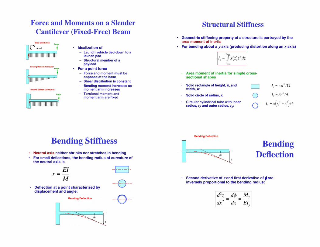
Force and Moments on a Slender
Cantilever (Fixed-Free) Beam
• Idealization of
– Launch vehicle tied-down to alaunch pad
– Structural member of apayload
• For a point force
– Force and moment must beopposed at the base
– Shear distribution is constant
– Bending moment increases asmoment arm increases
– Torsional moment andmoment arm are fixed
Structural Stiffness
• Geometric stiffening property of a structure is portrayed by thearea moment of inertia
• For bending about a y axis (producing distortion along an x axis)
• Area moment of inertia for simple cross-sectional shapes
• Solid rectangle of height, h, andwidth, w:
• Solid circle of radius, r:
• Circular cylindrical tube with innerradius, ri: and outer radius, ro:
!
Iy = wh3/12
!
Iy = "r4 /4
!
Iy = " ro4
# ri4( ) /4
!
Ix
= x z( )z2 dzzmin
zmax
"
Bending Stiffness
• Neutral axis neither shrinks nor stretches in bending
• For small deflections, the bending radius of curvature ofthe neutral axis is
!
r =EI
M
• Deflection at a point characterized bydisplacement and angle:
Bending
Deflection
• Second derivative of z and first derivative of & areinversely proportional to the bending radius:
!
d2z
dx2
=d"
dx=My
EIy

Maximum Deflection and
Bending Moment of Beams(see Fundamentals of Space Systems for additional cases)
Fixed-Free Beam Fixed-Fixed Beam Pinned-Pinned Beam
Ymax = maximum deflection Mmax = maximum bending moment
Maximum Deflection and
Bending Moment of Plates(see Fundamentals of Space Systems for additional cases)
Circular Plate
Rectangular Plate!
m =1/"
Typical Cross-Sectional Shear Stress
Distribution for a Uniform Beam
• Shear stress due to bending moment ishighest at the neutral axis
• Maximum values for various cross sectons(see Fundamentals of Space Systems)
Buckling
• Predominant steady stressduring launch is compression
• Thin columns, plates, andshells are subject to elasticinstability in compression
• Buckling can occur below thematerial!s elastic limit
!
"cr
=C# 2
E
L /$( )2
=P
A
Critical buckling stress of a column(Euler equation)
!
C = function of end " fixity"
E = modulus of elasticity
L = column length
" = I A = radius of gyration
Pcr = critical buckling load
A = cross sectional area

Effect of “Fixity” on Critical
Loads for Beam Buckling
• Euler equation
– Slender columns
– Critical stress below theelastic limit
– Relatively thick column walls
• Local collapse due to thinwalls is called crippling
Crippling vs. Buckling
Critical Stress for Plate and Cylinder Buckling
Bending Moment and Linear Deflection
due to a Distributed Normal Force
• Deflection is found by four integrations of the deflectionequation
!
d2
dx2EIy
d2z
dx2
"
# $
%
& ' x= xs
= N 'y xs( )
N!y(xs)
!
My x( ) = Ny (x)xmin
xmax
" x # xcm( )dx
= N 'y (x)xmin
xmax
" dx x # xcm( )dxxmin
xmax
"
!
N '(x) = normal force variation with length
Bending Vibrations of a
Free-Free Uniform Beam
!
EIyd4z
dx4
x= xs
= k = "m'd2z
dt2
x= xs
!
EIy = constant
m'= mass variation with length (constant)
k = effective spring constant
• Solution by separation of variables requires that left andright sides equal a constant, k
• An infinite number of separation constants, ki, exist
• Therefore, there are an infinite number of vibrationalresponse modes
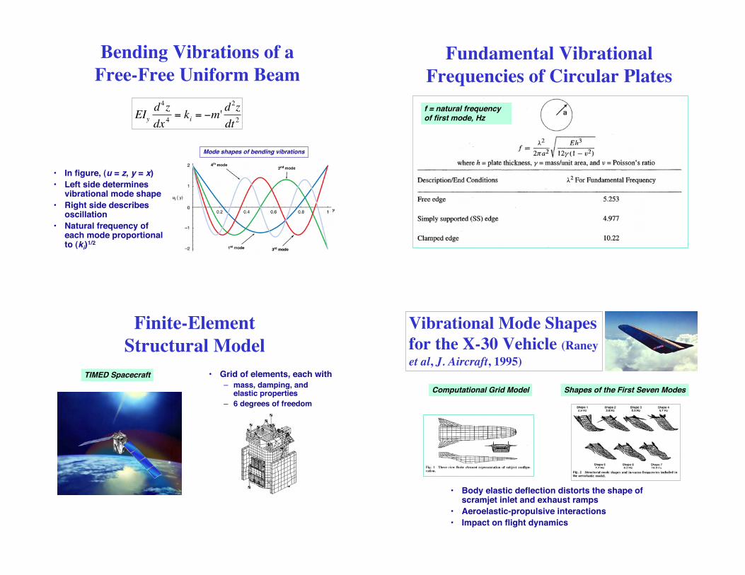
Bending Vibrations of a
Free-Free Uniform Beam
• In figure, (u = z, y = x)
• Left side determinesvibrational mode shape
• Right side describesoscillation
• Natural frequency ofeach mode proportionalto (ki)
1/2
Mode shapes of bending vibrations
!
EIyd4z
dx4
= ki = "m'd2z
dt2
Fundamental Vibrational
Frequencies of Circular Plates
f = natural frequencyof first mode, Hz
Finite-Element
Structural Model
TIMED Spacecraft • Grid of elements, each with
– mass, damping, andelastic properties
– 6 degrees of freedom
Vibrational Mode Shapes
for the X-30 Vehicle (Raney
et al, J. Aircraft, 1995)
Computational Grid Model
• Body elastic deflection distorts the shape ofscramjet inlet and exhaust ramps
• Aeroelastic-propulsive interactions
• Impact on flight dynamics
Shapes of the First Seven Modes

Next Time:Flight Path Guidance,
Navigation, and Control
Top Related