


![HS Series - Müggler Engineering ApS · Horizontal Machining Center HS Series, ... Best-in-class rapid traverse rate of 60m/min ... Low winding High winding 167 [123] 118 [87] 95](https://static.fdocuments.in/doc/165x107/5ac092da7f8b9ac6688c5331/hs-series-mggler-engineering-aps-machining-center-hs-series-best-in-class.jpg)


Languages
Pages
Legal


LF1600 SeriesHYUNDAI WIA Front Loading Turning Center

The Turning Center LF1600 Series, designed by Hyundai WIA with years of expertise and the latest technology, is a high performance machine designed for efficiency and maximum productivity.
Technical Leader
LF1600 Series
mm(in)
mm(in)
inch
mm(in)
r/min
kW(HP)
mm(in)
EA
Ø370 (14.6″)
165 (6.5″)
6″
Ø45 (1.8″)
4,500
7.5/5.5 (10/7.4)
140/165 (5.5″/6.5″)
2×10
Swing Over the Bed
Max. Turning Length
Chuck Size
Bar Capacity
Speed (rpm)
Motor (Max/Cont.)
Travel(X/Z)
No. of Tool

Twin Spindle Front Loading CNC Turning Center
LF1600 Series● High speed gantry loader installation for cycle time reduction (Option)
● Vibration minimized through separated bed structure
● Symmetrical heat behavior headstock structure to minimize thermal displacement
● Box guideway for all axes
● High rigidity servo turret
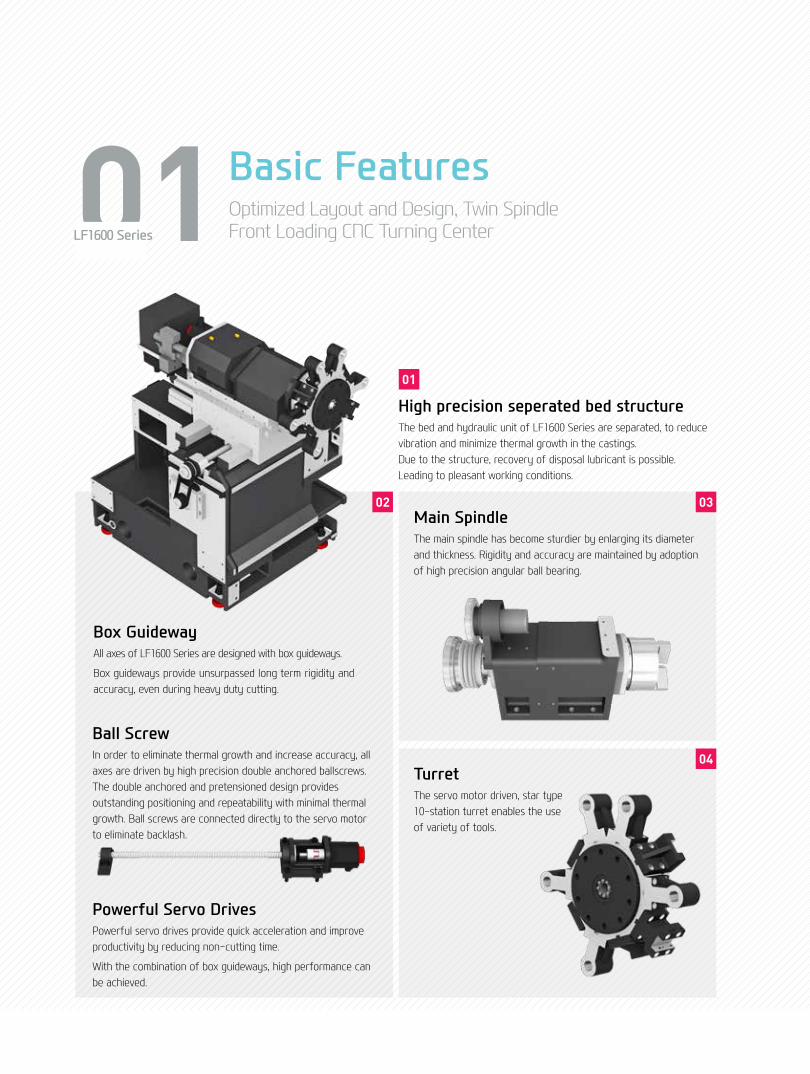
01 Basic FeaturesOptimized Layout and Design, Twin Spindle Front Loading CNC Turning CenterLF1600 Series
Main SpindleThe main spindle has become sturdier by enlarging its diameter and thickness. Rigidity and accuracy are maintained by adoption of high precision angular ball bearing.
TurretThe servo motor driven, star type 10-station turret enables the use of variety of tools.
04
0302
High precision seperated bed structureThe bed and hydraulic unit of LF1600 Series are separated, to reduce vibration and minimize thermal growth in the castings. Due to the structure, recovery of disposal lubricant is possible. Leading to pleasant working conditions.
01
Box GuidewayAll axes of LF1600 Series are designed with box guideways.
Box guideways provide unsurpassed long term rigidity and accuracy, even during heavy duty cutting.
Ball ScrewIn order to eliminate thermal growth and increase accuracy, all axes are driven by high precision double anchored ballscrews. The double anchored and pretensioned design provides outstanding positioning and repeatability with minimal thermal growth. Ball screws are connected directly to the servo motor to eliminate backlash.
Powerful Servo DrivesPowerful servo drives provide quick acceleration and improve productivity by reducing non-cutting time.
With the combination of box guideways, high performance can be achieved.

◉ Rapid Traverse Rate (X/Z axis) : 24/24 m/min (944.8/944.8 ipm)
◉ Travel (X/Z axis) : 140/165 mm (5.5″/6.5″)
◉ Spindle Speed : 4,500 rpm ◉ Spindle Output (Max./Cont.) : 7.5/5.5 kW (10/7.4 HP)
◉ Spindle Torque (Max./Cont.) : 64/47 N.m (47.2/34.7 lbf.ft)
Reduction of non-cutting time
04+
05
LF
1600
Ser
ieS
Fron
t Loa
ding
Tur
ning
Cen
ter
HYU
ND
AI W
IAM
ACH
INE
TOO
L
Basic Structure
01
03
0402
◉ Convenient Coolant Tank Front side separation of coolant tank makes maintenance and repairs more convenient.

02 High Precision SpindleLong Lasting High Accuracy & Excellent PerformanceCNC Turning CenterLF1600 Series

06+
07
LF
1600
Ser
ieS
Fron
t Loa
ding
Tur
ning
Cen
ter
HYU
ND
AI W
IAM
ACH
INE
TOO
L
Spindle Processing Flow
Spindle
Main SpindleRigidity is significantly improved by enlarging the spindle diameter and thickness. Also, accuracy is increased due to the use of highly reliable bearings.
This improves durability and provides a high quality surface finish on every machined part.
C-Axis ControlLF1600M/2SP features C-axis 0.001˚ controls, enabling the machining of various shapes and dimensions.
Parts requiring secondary operations are transferred from Z1 spindle to Z2 spindle
Same parts can be processed simultaneously by utilizing both spindles of Z1/Z2-axis with same parts.
Different parts can be processed simultaneously by utilizing both spindles of Z1/Z2-axis with various parts.
0.001°
Power (kW[HP])
64N∙m[47.2lbf∙ft] (30min)120N∙m[88.5lbf∙ft] (30min)
7.5kW[10HP] (30min)
11kW[14.7HP] (30min)47N∙m[34.7lbf∙ft] (Cont.)81.4N∙m[60lbf∙ft] (Cont.)
5.5kW[7.4HP] (Cont.)7.5kW[7.4HP] (Cont.)
Torque (N∙m[lbf∙ft])
Spindle Speed (r/min) Spindle Speed (r/min)
Power (kW[HP]) Torque (N∙m[lbf∙ft])
10[13.4]
5[6.7]
70[51.6]60[44.2]
40[29.5]
5[3.7]
120[88.5]100[73.7]
50[36.8]
10 500 1,125 3,000 4,5001[1.3]
10[13.4]
5[6.7]
10 500 1,000875 2,000 3,000 3,5001[1.3]
LF1600 Series

03 Servo TurretHigh speed, High Accuracy, Highly Reliable Servo Turret LF1600 Series
Turret LF1600 Series is designed with high performance AC servo motors to enhance process reliability. Especially, 3-piece couplings enable accurate indexing. Also, powerful hydraulic tool clamping minimizes tools tip deviation caused by the load of tools, leading to excellent performance even during heavy duty operations.
◉ Number of Tool : 2×10 EA
◉ Tool Size (O.D) : □20 (□0.8″)
◉ Tool Size (I.D) : Ø32 (Ø1.2″)
◉ Indexing Time : 0.25 sec/step

08+
09
LF
1600
Ser
ieS
Fron
t Loa
ding
Tur
ning
Cen
ter
HYU
ND
AI W
IAM
ACH
INE
TOO
L
Turret
BMT turret increases tool performance and rigidity by securing each tool with 4 screws.
Overall cutting power and capability has improved for all applications.
Mill Turret (BMT55P)
Machining Variation
Mill Tool HolderMachining capability has increased with the addition of straight milling head tool holder, which can machine workpieces from the side, and angular milling head tool holder, which can perform I.D. operations.
A wide variety of additional tool holders for drilling and tapping can further enhance machining operations.
Angular Milling HeadStraight Milling Head
◉ Output (Max.) : 3.7/2.2 kW (5/3 HP)
◉ Speed : 4,000 rpm
◉ Collet Size : Ø16 (Ø0.6″) (ER25)
◉ Live Tool Type : BMT55P
O.D Cutting
I.D Cutting
End Milling
Drilling
Drilling
I.D Threading
Ball-End Milling
Face Milling

Machine Monitoring
Energy SavingIntelligent Machining
Easy Programming
HW-MMS HW
-ESS
HW-DPRO T/TM
User Friendly
HW-TM
HYUNDAI WIA Smart System for CNC Turning Center
User Convenience
HW-eDNC
HW-MCG
HW-PGi F (HYUNDAI WIA Programming Guide i for Fanuc System)(Standard)
Realistic 3D solid animationProgramming simulation
Example of easy programmingEasy programming interactively
without code
Engraving CycleProgramming with only entering text by
controlling C-axis
04 Smart SystemSoftware for Smart Operating and MachiningLF1600 Series

HYUNDAI WIA Smart System
Faster processing and enhanced accuracy in are possiblethrough the HYUNDAI WIA Smart System. The user friendly software and equipment monitoring of the Smart System maximizes productivity.
HW-GLM (HYUNDAI WIA Gantry Loader Manager)
Set the position coordinates and the loader driver support features such as easy and convenient way to provide the user operating the loader to be used to support the software
10+
11
LF
1600
Ser
ieS
Fron
t Loa
ding
Tur
ning
Cen
ter
HYU
ND
AI W
IAM
ACH
INE
TOO
L
HW-DPRO T/TMHYUNDAI WIA Dialogue PROgram Turn/TurnMill
Using a dialogue method, this software makes it easy to work out a program for a lathe processing operation with complicated configurations. (Can be installed on a PC.)
HW-MMSHYUNDAI WIA Machine Monitoring System
This software is for remote control monitoring of equipment status (mobile, PC.) It checks and manages the state of multiple machines and the progress of processing on a real time basis.
HW-TMHYUNDAI WIA Tool Monitoring
A tool monitoring software which analyzes the load of the spindle motor to determine and monitor possible damage of tools.
HW-ESSHYUNDAI WIAEnergy Saving System
An environmental friendly software that reduces the unnecessarily wasted standby power waiting for an operation.
HW-eDNCHYUNDAI WIA ethernet Direct Numerical Control
This software allows transmition of NC data between PC and a machine's CNC. The processing programs can be managed on the PC through the ethernet or serial communication.
HW-MCGHYUNDAI WIAMachine Guidance
Software that offers operation, maintenance, management monitoring and various user friendly features.

05 Automation SystemVarious Devices for User Convenience
LF1600 Series
◉ Gantry Loader Work Size : Ø120 x 80 mm (Ø4.7″ x 3.1″)
◉ Gantry Speed (X/Y/Z) : 150/110/60 m/min
◉ Gantry Loader Work Weight : 3 kg (6.6 lb) x 2 ea
◉ No. of Pallets : 14 Pallets with 3 Bars
◉ Pallet Speed : 1.7 m/min (8 sec / 1 pitch)
◉ Lifting Speed (Up-Down) : 3 m/min
Gantry Loader
Work Feeder
End Product 2nd Machining
The high speed gantry loaders and the work stocker allow the implementation of automation cells. This enables machining process flexibility and productivity enhancement.
Gantry Loader Machining Process
Raw Material 1st MachiningUnloading & Loading
Unloading & Loading
Turn Over

SPECiFiCATiONS
Standard & Optional
Main SpindleHollow Chuck 3 JawMain SpindleSolid Chuck 3 JawStandard Soft Jaw (1set)Chuck Clamp Foot Switch2 Steps Hyd, Pressure Device2 Steps Foot SwitchSpindle Inside StopperChuck Open/Close Confirmation DeviceMain Spindle 5° IndexC-Axis (0.001°)TurretTurretMill TurretStraight Mill Holder (Radial)Angular Mill Holder (Axial)Straight Mill Holder (Radial)Angular Mill Holder (Axial)Boring SleeveDrill SocketU-Drill HolderU-Drill Holder SleeveO.D Extension HolderSwivel HeadTail Stock & Steady RestQuill Type Tail StockTail Stock Foot SwitchStandard Live CenterHigh Precesion Live Center2 Steps Tail Stock Pressure SystemCoolant & Air BlowStandard Coolant (Nozzle)Chuck Coolant (Upper Chuck)Gun CoolantThrough Spindle Coolant(Only Hollow Cylinder & Special Chuck)Thru Coolant for Live ToolChuck Air Blow (Upper Chuck)Tail Stock Air Blow (Upper Tail Stock)Turret Air BlowAir GunThrough Spindle Air Blow(Only Hollow Cylinder & Special Chuck)High Pressure CoolantPower Coolant System (For Automation)Coolant ChillerChip DisposalCoolant TankChip Conveyor Hinge(Tank Position/Chip Disposal) ScraperSpecial Chip Conveyor (Drum Filter)
Chip Wagon
Safety DeviceDoor Inter-LockTotal Splash GuardQuill Forward/Reverse Confirmation DeviceChuck hydraulic pressure maintenance interlockBack Spin Torque Limiter (BST)Torque Limiter
8″10″8″10″
RadialCollet Type,2eaCollet Type,2eaAdapter TypeAdapter Type
For Out-Dia
6Bar (87psi)
220ℓ(58.1 gal)
Front (Rear)
Standard(180ℓ[47.5 gal])Swing(200ℓ[52.8 gal])Large Swing(290ℓ[76.6 gal])Large Size(330ℓ[87.2 gal])Customized
Spindle Electric Device
● : Standard ○ : Option ☆ : Prior Consultation - : Non Applicable
LF1600/2SP LF1600M/2SP ○ ○ ☆ ☆ ● ● ☆ ☆ ● ● ● ● ○ ○ ○ ○ ☆ ☆ ○(CE:●) ○(CE:●) ☆ ☆ - ● ● ● - ● - ● - ● - ○ - ○ ● ● ● ● ○ ○ ○ ○ ☆ ☆ - ☆ - - - - - - - - - - ● ● ● ● ○ ○
☆ ☆
- ○ ○ ○ ☆ ☆ ☆ ☆ ○ ○
☆ ☆ ● ● ☆ ☆ ☆ ☆ ● ●
○ ○
☆ ☆
○ ○
○ ○
○ ○
○ ○
☆ ☆ ● ● ● ● - - ○(CE:●) ○(CE:●) ● ● ☆ ☆
LF1600/2SP LF1600M/2SP ● ● ○ ○ ○ ○ ○ ○ ○ ○ ○ ○ - - ○ ○ ○ ○ ○ ○ ○ ○ ○ ○ ○ ○ ● ● ☆ ☆ - - ○ ○ ○ ○ ☆ ☆ ○ ○ - - ☆ ☆ ☆ ☆ ☆ ☆ ○ ○ ○ ○ ☆ ☆ ☆ ☆ ○ ○ ○ ○ ○ ○ ☆ ☆ ☆ ☆ ☆ ☆ ☆ ☆ ● ● ☆ ☆ - - - - ○ ○ ☆ ☆ ○ ○ ○ ○ ☆ ☆ ☆ ☆ ☆ ☆ ☆ ☆ ☆ ☆ ☆ ☆ ● ●
● ●
☆ ☆ ○ ○ ○ ○ ○ ○ ☆ ☆ ☆ ☆ ☆ ☆ ● ● ☆ ☆ ☆ ☆
Call LightCall LightCall Light & BuzzerElectric Cabinet LightRemote MPGSpindle Load MeterSpindle Speed MeterWork CounterTotal CounterTool Counter
Multi Tool Counter
Electric Circuit BreakerABS EncoderAVR (Auto Voltage Regulator)
Transformer
Auto Power OffDouble Foot SwitchMeasurementQ-SetterAutomatic Q-SetterWork CloseConfirmation DeviceWork Setter
Linear Scale
Coolant Level Sensor (Only for Chip Conveyor)Measuring SystemEnvironmentAir ConditionerDehumidifierOil Mist CollectorOil Skimmer (Only for Chip Conveyor)MQL (Minimal Quantity Lubrication)Fixture & Automation
Auto Door
Auto Shutter (Only for Automatic System)Sub Operation PannelBar Feeder InterfaceBar Feeder (FEDEK)Extra M-Code 4eaAutomation Interface
I/O Extension (IN & OUT)
Turret Work Pusher (For Automation)GANTRY Automation SystemTurn Over DeviceIn Stocker (Rotary)OUT Stocker (Rotary)NG ChuteHyd. DeviceStandard Hyd. Cylinder
Standard Hyd. Unit
S/WMachine Guidance (HW-MCG : FANUC)Tool Monitoring (HW-TM : FANUC)DNC Software (HW-eDNC : FANUC)Interactive ProgramEnergy Saving System (HW-ESS : FANUC)Machine Monitoring System (HW-MMS : FANUC)Load Master (HW-GLM : FANUC)ETCTool BoxCustomized ColorCAD & CAM
1 Color : ■3 Color : ■■■3 Color : ■■■B
LED TypeLED TypeDigitalDigitalDigital6ea9ea
30kVA35kVA
Removable Type
TACOSMC
X AxisZ Axis
For Automation
StandardHigh Speed
16Contact32Contact
8/10/12/14 Pos8/10/12/14 Pos
Solid35bar (507.6 psi) / 15ℓ(4 gal)
Need Munsel No.
Specifications are subject to change without notice for improvement.
LF
1600
Ser
ieS
Fron
t Loa
ding
Tur
ning
Cen
ter
HYU
ND
AI W
IAM
ACH
INE
TOO
L
12+
13

unit : mm(in)External Dimensions
SPECiFiCATiONS
RearChip Conveyor
1900 (74.8)
3814 (150.1)
1936 (76.2)
2782
(109
.5)
1200
(47.
2)
3054 (120.2)

unit : mm(in)Tooling System
14+
15
LF
1600
Ser
ieS
Fron
t Loa
ding
Tur
ning
Cen
ter
HYU
ND
AI W
IAM
ACH
INE
TOO
L
O.D Holder
I.D Holder
Facing Holder
O.D Holder
I.D Holder
Facing Holder
Straight MillHolder
Angular MillHolder
SPECiFiCATiONS
Right/Left
Single
Tool Holder
Standard
Standard
Ø8 (5/16″)
Ø10 (3/8″)
Ø12 (1/2″)
Ø16 (5/8″)
Ø20 (3/4″)
Ø25 (1″)
MT 1 × MT 2
MT 2
O.D Holder
Facing Holder
I.D Holder
U-Drill Tool Holder
Stright Mill Holder
Angular Mill Holder
Boring
Drill
ER Collet
Turning Holder
Driven Holder
Boring Holder
Socket
iTEM LF1600/2SP LF1600M/2SP
8 6
2 2
10 8
- Opt
- 2
- 2
2 2
2 2
2 2
2 2
2 2
2 2
2 2
2 2
- 2 Set
Tooling Parts Detail
Specifications are subject to change without notice for improvement.
LF1600/2SP
10 StationBMT 55P
10 Station
LF1600M/2SP

unit : mm(in)interference
360 (14.2)
135 (5.3) 135 (5.3) 65(2.5)
30(1.2)
130 (5.1)
140 (5.5)(X1 STROKE)
140 (5.5)(X STROKE)
95(3.7)
270(10.6)
10(0.4)
95 (3.7)
95 (3.7)
95 (3
.7)
95 (3
.7)
ø188
(ø7.4)
ø188(ø7.4)
ø180(ø7.1) ø186
(ø7.3)
ø193
(ø7.6) ø186
(ø7.3)
ø530
(ø20.8)
360 (14.2)
135 (5.3) 135 (5.3) 65(2.5)
100(3.9)
30(1.2)
130 (5.1)
95(3.7)
270(10.6)
10 (0.4)
ø530
(ø20.8)
ø260
(ø10.2)
ø165(ø6.5)
ø260
(ø10.2)
ø165(6.5)
ø165
(ø6.5)
ø165
(ø6.5
)
LF1600/2SP
LF1600M/2SP
SPECiFiCATiONS

unit : mm(in)Tooling Travel Range
I.D TOOLHOLDER
O.D TOOLHOLDER
ANGULAR MILLHOLDER
STRAIGHT MILLHOLDER
I.D TOOLHOLDER
O.D TOOLHOLDER95 (3.7)
360 (14.2)360 (14.2)
140 (5.5)(X STROKE)
15(0.6)
100(3.9)
Ø165 (Ø6.5)
370 (14.5)
40(1.6)
84(3.3)
34(1.3)
140 (5.5)
165 (6.5)
(Z STROKE)
125 (4.9)125 (4.9)
95 (3.7)
165 (6.5)
(Z STROKE)
10(0.4)
130 (5.1)
11(0.4)
22 (0.8)
120 (4.7)
135 (5.3)135(5.3)
Ø165 (Ø6.5)
340 (13.4)
115 (4.5)
214 (8.4)
65(2.6)
30(1.2)
(X STROKE)(X STROKE)
40(1.6)
84(3.3)
164 (6.5)
(Z STROKE)
119 (4.7)
(Z STROKE)46(1.8)
135 (5.3)
84 (3.3)
34 (1.3)
45(1.7)
Ø32(Ø1.3)
34(1.3)
1
95 (3.7)
360 (14.2)360 (14.2)
15(0.6)
100 (3.9)
Ø165 (Ø6.5)
370 (14.5)
165 (6.5)
165 (6.5)
125 (4.9)125 (4.9)
10(0.4)
130 (5.1) 120 (4.7)
140 (5.5) 135 (5.3)140 (5.5)135 (5.3)
Ø165 (Ø6.5)
65(2.6)
80 (3.1)
70(2.7)
70(2.7)
72 (2.8)
Ø165 (Ø6.5)
95 (3.7)
73 (2.8)
(X STROKE)
165 (6.5)
(Z STROKE)
40(1.6)
84(3.3)
21(0.8)
10(0.4)
130 (5.1)120 (4.7)
139.5 (5.5)
5(0.2)
140(5.5)
105(4.1)
34(1.3)
21.5
(0.8)
Ø165 (Ø6.5)
139(5.5)
84(3.3)
40(1.6)
140 (5.5)
360 (14.2)360 (14.2) 370 (14.5)
135 (5.3)135 (5.3)
140 (5.5)(X STROKE)
165 (6.5)
(Z STROKE)
(X STROKE)
140 (5.5)
LF1600/2SP
LF1600M/2SP
16+
17
LF
1600
Ser
ieS
Fron
t Loa
ding
Tur
ning
Cen
ter
HYU
ND
AI W
IAM
ACH
INE
TOO
L
SPECiFiCATiONS

Specifications are subject to change without notice for improvement.
Swing Over the Bed
Max. Turning Dia.
Max. Turning Length
Bar Capacity
Chuck Size
Spindle Bore
Spindle Speed (rpm)
Motor (Max/Cont.)
Torque (Max/Cont.)
Spindle Type
Spindle Nose
C-axis Indexing
Travel (X/Z)
Rapid Traverse Rate (X/Z)
Slide Type
No. of Tool
Tool Size OD
ID
Indexing Time
Motor (Max/Cont.)
Milling Tool Speed (rpm)
Touque (Max/Cont.)
Collet Size
Type
Coolant Tank
Lubricating Tank
Electric Power Supply
Thickness of Power Cable
Voltage
Floor Space (L×W)
Height
Weight
Controller
CAPACITY
FEED
TANkCAPACITY
SPINDlE
TURRET
lIvE TOOl
MACHINE
NC
POWERSUPPlY
mm(in)
mm(in)
mm(in)
mm(in)
mm(in)
mm(in)
r/min
kW(HP)
N.m(lbf.ft)
-
-
deg
mm(in)
m/min(ipm)
-
EA
mm(in)
mm(in)
sec/step
kW(HP)
r/min
N.m(lbf.ft)
mm(in)
-
ℓ(gal)
ℓ(gal)
kVA
Sq
V/Hz
mm(in)
mm(in)
kg(lb)
-
iTEM LF1600M/2SPLF1600/2SP
Ø370 (14.6″)
Ø260 (10.2″)
165 (6.5″)
Ø45 (1.77″)
ø165 (6.5″)
ø53 (2.1″)
4,500
7.5/5.5 (10/7.4)
64/47 (47.2/34.7)
BELT
A2-5
- 0.001˚
140/165 (5.5″/6.5″)
24/24 (944.9/944.9)
BOX GUIDE
2×10
□20 (0.8″)
ø32 (1.3″)
0.25
- 3.7/2.2 (5/3)
- 4,000
- 26.2/14 (19.3/0.3)
- Ø16 (0.6″) ER25
- BMT55P
220 (58.1)
4 (1)
25
Over 25
220/60 (200/50)
1,900×1,936 (74.8″×76.2″)
2,210 (87″)
4,500 (9,921)
FANUC 31i-A
Specifications [ ] : Option
SPECiFiCATiONS

Figures in inch are converted from metric values.Specifications are subject to change without notice for improvement.
18+
19
LF
1600
Ser
ieS
Fron
t Loa
ding
Tur
ning
Cen
ter
HYU
ND
AI W
IAM
ACH
INE
TOO
L
CONTROLLER
FANUC 31i-AAxis control / Display unit
Controlled axes
Simultaneous controllable axes
Least input increment
Least command increment
High speed HRV controlInch / Metric conversionInterlockMachine lockEmergency stopStored stroke check 1Stored stroke check 2Stored stroke check 3Follow-upServo-off
Backlash compensation
Position switchUnexpected disturbance torque detectionHigh resolution transfer control (HRM)LCD / MDIOperation Automatic operation (memory)MDI operationSearch functionProgram restartWrong operation preventionBuffer registerProgram check functionSingle blockFeed functionsManual jog feedManual handle feedrateFeed commandFeedrate overrideJog overrideRapid traverse overrideOverride cancelFeed per minute / rotationProgram input & interpolation functions
Nano interpolation
DwellThread retractVariable lead threading1st reference point returnReference point return check2nd reference point returnProgram stop / EndTape codeOptional block skipMaximum programmable dimensionsProgram numberAbsolute and incremental programmingDecimal point inputPlane selectionWork coordinate system selectionManual absoluteDirect drawing dimension programmingG code systemProgrammable data inputSub program callCustom macro BAddition of custom macro common variableMultiple repetitive cyclesMultiple repetitive cycles ⅡCanned cycles for turning
Max. 9 axes are availableX1, Z1, X2, Z2 axesX1, Z1, X2, Z2, C, C2 axes X1, Z1, X2, Z2, XG, YG, ZG axes X1, Z1, X2, Z2, C1, C2, XG, YG, ZG axes 2axes / Linear and circular (Max. 4axes)X, Z, Y, B axis : 0.001 mm (0.0001”)C axis : 0.001 degX, Z, Y, B axis : 0.001 mm (0.0001”)C axis : 0.001 deg
G20 / G21Each axis / All axisAll axis
Over-travel
+/- 0~9999 pulses(Rapid traverse & cutting feed)
Back-spin torque limiter (BST)
10.4″ Color LCD
Sequence, program
Dry run., program check
Rapid, jog, handlex1, x10, x100F code feedrate direct command0~200 % (10% units)0~2,000 mm/min[79 ipm]F1, F5, F25 / 50, F100%
Positioning/Linear/Circular(G00/G01/G02, G03)G04, 0~9999.9999 sec
G28, manualG27G30M00, M01 / M02, M30EIA / ISO 1 ea+/- 9999.9999″O+4 digits
G17, G18, G19G52 to G59“ON” fixed
Included chamfering / Corner R`AG1010 Step#100 to #199, #500 to #999
Sub / Main spindle functionM-Code functionM-Code function lockLock sp. speed commandMain sp. constant controlSpindle speed overrideSpindle position decisionRigid tappingTool function / Tool compensationTool functionTool offset pairsTool offsetTool nose radius compensationDirect input of measured toolcompensation value BTool life managementData in/output & editing functionsInput/Output interfaceMemory card input/outputEmbeded ethenetPart program storage lengthNumber of registrable programs expansionMemory lockBackground editingExtended part program editionDisplay, diagnosis & setting functionsSelf-diagnosis functionHistory displayHelp functionExternal messageRun hour / Parts count displayDisplay of actual spindle speed and T codeActual cutting feedrate displayOperating monitor screenGraphic displaySpindle / Servo setting screenSelection of 5 optional languageLCD screen saveAutomatic data backupFunctions according to machine specificationCs contouring controlStored pitch error compensationPolar coordinate interpolationCylindrical interpolationCanned cycles for drillingspindle orientation expansion
OptionHigh speed ethernetOptional block skip3rd & 4th reference point returnG code systemPart program storage lengthTool OffestPoligon TurningHelical interpolationDynamic graphic displayProtection of data at 8 levelsManual guide i
M4 digits
S4 digits, binary outputG96, G9750% to 150% (10% units)
T2 + 264 pairs
G40, G41, G42
RS232C
100Mbps256 KbyteMax. 1,00 programs
Copy, move, change of NC program
Alarm & operation display
Rod meter light
Screen saver
Turn millTurn millTurn millTurn millTurn millTurn mill
100 Mbps (Option board is required)9 ea
B / C1mb / 2mb99 / 200 / 400 EA
Interactive program

GLOBAL NETWORk

20+
21
LF
1600
Ser
ieS
Fron
t Loa
ding
Tur
ning
Cen
ter
HYU
ND
AI W
IAM
ACH
INE
TOO
L
Changwon Technical Center / R&D Center / Factory153, Jeongdong-ro, Seongsan-gu, Changwon-si, Gyeongsangnam-do, Korea (Zip Code : 51533)TEL : +82 55 280 9114 FAX : +82 55 282 9680
Uiwang Technical Center / R&D Center37, Cheoldobangmulgwan-ro, Uiwang-si, Gyeonggi-do, Korea (Zip Code : 16082)TEL : +82 31 596 8209 Fax : +82 55 210 9804
HeADqUARTeR
OVeRSeAS OFFICeSHYUNDAI WIAMachine Tools America 265, Spring Lake Drive, Itasca, IL, 60143
TEL : +1 201 489 2887 FAX : +1 201 489 2723
Jiangsu HYUNDAI WIANo.6 Fenghuang Road, Fenghuang Town, Zhangjjagang City, Jiangsu province, China
TEL : +86 512 5672 6808FAX : +86 512 5671 6960
Chengdu OfficeNO.508 Room, B Block, AFC Plaza, NO.88 Jiaozi Road, High-tech Zone, Chengdu, China 610041
TEL : +86 28 8665 5550FAX : +86 28 8666 2985
HYUNDAI WIAMachine Tools europe Kaiserleipromenade 5, D-63067 Offenbach, Germany
TEL : +49 69271 472 701FAX : +49 69271 472 719
Hyundai WIA Machine Tools ChinaShanghai Office1-3F, Bldg6, No.1535 Hongmei Road, Xuhui District, Shanghai, China, 200233
TEL : +86 21 6427 9885FAX : +86 21 3431 0376
Wuhan Office Room 302, B tower, Donghe Center, Dongfeng three road, Zhuankou, Wuhan, Hubei, China 430056
TEL : +86 27 5956 3256~7FAX : +86 27 5952 3258
Raunheim Service CenterRaunheim R&D CenterKelsterbacher Strasse 51, 65479 Raunheim, Germany
TEL : +49 6142 9256 0 FAX : +49 6142 834 100
Beijing Office13 Floor Building B Zhonghangji square, No.15 Ronghua South Road, Yizhuang Economic and Technological Development Zone District, Beijing, China 100176
TEL : +86 10 8453 9850~2FAX : +86 10 8453 9853
qingdao OfficeRoom 1207, Caifu Building, 182-6 Haier Middle Road, Qingdao, China 266061
TEL : +86 532 8667 9333~5FAX : +86 532 8667 9338
Inida Office#4/169, Rajiv Gandhi Salai, (OMR), Kandanchavadi, Chennai-600 096, Tamilnadu, IndiaTEL: +91-44-3290-1719
Guangzhou OfficeRoom 311, Unit 1-3, Poly Tal Tu Wun, Hanxi Avenue, Panyu District, Guangzhou, China 511400
TEL : +86 20 8550 6595~6 FAX : +86 20 8550 6597
Shenyang OfficeRoom 1304, NO.53 Beizhan Road, Shenhe District, Shenyang, China 110013
TEL : +86 24 3228 6640FAX : +86 24 3228 6642

2015-12 003.002 ENG
Head Office & Factory153, Jeongdong-ro, Seongsan-gu, Changwon-si, Gyeongsangnam-do
Tel +82 55 280 9206, 9299 Fax +82 55 210 9804
machine.hyundai-wia.com
Overseas Sales Team16F, 37, Cheoldobangmulgwan-ro, Uiwang-si, Gyeonggi-do
Tel +82 31 593 8173
Top Related