


Languages
Pages
Legal


Biochemistry 9001: Protein Structure Determination by Electron Microscopy Summer 2016
Laboratory 1: General TEM operations on JEOL JEM 1400
Training Guide: JEOL JEM 1400
Load Specimens o Provide a general explanation during pumping
Electrons emitted from filament Pass through lenses Then through sample Then projected onto phosphorescent screen
press “F1” on right hand panel to raise/lower screen Finally onto CCD
Turn on filament at proper voltage o Create folder in DM with clients name and date on
H:/Images/cient/date o Create string to build
Hammer/Wrench icon > “Save Numbered” Provide string name Reset number to 1
Z-height adjustment o Press “STD FOCUS” button under the cover o Find section or feature o Press “IMAGE WOBBLE X” or “IMAGE WOBBLE Y” o Adjust Z height on JEOL GUI by selecting
Micron increment Up/down arrows Watch for sample to slow/stop wobbling
Explain “BRIGHTNESS” knob o Crossover –
demonstrate in low mag off of resin section (will burn through) converging beam or “to the right” of crossover
pneumonic device “crossover has two ‘R’s’ explain importance of not approaching crossover
low mag to not burn through resin sections
to not overexpose the CCD camera a good brightness is filling the viewing screen with the beam so the
edge of beam is seen on edge of screen
Explain “MAGNIFICATION” knob o Show on JEOL GUI where the magnification is displayed, ensure Digital
Micrograph is responding o Show how at higher mags the beam gets dimmer, so need to condense or
“brighten” beam using BRIGHTNESS knob (turn to left to approach crossover)
o Reiterate after condensing beam at higher mags, decreasing mags will give a beam close to crossover – warn about overdosing CCD

Biochemistry 9001: Protein Structure Determination by Electron Microscopy Summer 2016
Laboratory 1: General TEM operations on JEOL JEM 1400
Explain “FOCUS” o 4 levels of focus (coarse-coarse, coarse, coarse-fine and fine) o Using “Live FFT” and acquiring images, show the concepts of focus,
overfocus and underfocus. Focus – features don’t have sharp edge and Thon rings are
expanded Underfocus – features have a white edge and Thon rings collapse
to center Overfocus – features have inverted edge (white, then dark) and
Thon rings collapse to center with o Explain Objective Astigmatism - FFT not round, but oval…assess at high
underfocus, then again close to focus
Explain “View” and “Acquire” image o Save with floppy disk 123 o Close image after saving o Measuring features, resaving.
Switching between samples in PentaHolder o Note which sample you are currently on by
look at the inner dot (white) Look at the numbered dot on the outer, ridged neural knob Switch to next sample by turning the outer, ridged, numbered
neural knob (BUT NOT THE OUTERMOST SMOOTH END) Repeat steps for “Z-height adjustment”
“STD FOCUS” and Z up/down

Biochemistry 9001: Protein Structure Determination by Electron Microscopy Summer 2016
Laboratory 1: General TEM operations on JEOL JEM 1400 Objective: Familiarize students with general operations and imaging with JEOL JEM 1400 Transmission Electron Microscope. Visualizing gold & negatively stained proteins.
Questions to be answered………………………………………………..Due 6/13/2016
1. Draw a schematic of the TEM. Please label filament, condenser lenses & aperture,
objective lens and aperture, specimen, projection lenses, screen and CCD camera. Explain what each component does.
2. Explain how focusing differs in the TEM compared to the light microscope.
3. Explain what the “Live FFT” shows you. Please include a drawing showing what a low resolution, highly defocused FFT looks like versus a high resolution, low defocus FFT.
4. Explain three mechanisms of contrast in TEM.

Biochem 9001 “Protein Structure Determination using Electron Microscopy”
Laboratory 2: Negative Staining of Keyhole Limpet Haemocyanin (KLH)
Introduction:
This laboratory should provide a basic foundation on how to prepare
negatively stained specimens for visualization with TEM and ultimately,
structure determination via single particle analysis. There are many variables
to be controlled for in the negative stain experiment. For negative staining,
sample concentrations need to be optimal, staining performed with the
proper reagent with proper concentration, and optimal staining thickness
for fully embedding the protein of interest.
Sample:
Megathura crenulata (Keyhole Limpet) Haemocyanin (5 mg/mL in PBS pH 7.2 containing 1mM CaCl2 and 0.5 mM MgCl2 with 15 mM sodium azide as preservative) from Sigma Aldrich (H8283).
Objective:
Students should learn the basics of negative staining and grasp some variables that come into play when
performing these experiments. The experiments contained within will allow you to visualize the effects
of the following: 1) sample concentration 2) negative stain composition & 3) stain thickness. Students
will learn how to perform glow discharge, perform dilutions of protein specimens, apply negative stain
reagents, TEM operation and image acquisition.
Questions to be answered:
1. Describe negative staining. Why is fully embedding your protein specimen in negative stain
important? How does this allow us to visualize the structure of a protein?
2. Were your replicate negatively stained specimens look the same? Please describe for both
Experiment 1 & Experiment 2. Why or why not? Describe three variables of a negative staining
experiment that you can change.
3. What does glow discharge do? Name two parameters can you vary to alter the glow discharge
conditions.
4. Which negative stains are better for membrane proteins or specimens with detergents? Which stains
have a more neutral pH?
9Å cryo-EM reconstruction of
Keyhole limpet hemocyanin
(KLH). EMDB entry EMD-1569.

Experiment 1: Effect of Protein Concentration on Negative Staining
1. From 5 mg/mL stock KLH solution, prepare 2 dilutions using water.
a. 1:10, 1:50
2. Prepare 5 freshly glow discharged (Pelco Easiglow Glow Discharge) carbon film grids (200 mesh, 50
nm carbon coated) with a negative charge.
a. Ensure carbon side (blue) of grid is facing up, place on a glass slide inside a glass petri dish on
filter paper.
b. Use default glow discharge conditions to prepare a negatively charged grid (0.39 mBar
vacuum, 10 sec vacuum stabilization, 45 sec glow discharge).
c. Remove freshly discharged grids from unit, place in petri dish, and cover with lid – use
IMMEDIATELY.
3. Place each grid in an anti-capillary, reverse action forcep (should have 5 grids in 5 forceps) lined up
overhanging the edge of pipet tip box.
4. Add 5 microliters of each protein dilution to each grid. Incubate 5 minutes.
5. Get 5 microliters of negative stain solution (2 % Uranyl Acetate) ready to dispense.
6. Gently blot using filter paper triangle from side, wick to “shininess” and immediately add your stain.
NOTE: DO NOT LET YOUR SAMPLE COMPLETLY DRY, this ruins the protein’s structure
7. After 5 minutes, remove the stain with filter paper triangle to dryness.
8. Load into TEM for visualization and determine best dilution to utilize for following experiment.
Sample should be well-dispersed with ~10-15 KLH protein particles per field of view at 15,000X
magnification.
Experiment 2: Speed of drying vs. particle embedding
1. Using the concentration you determined looked best in the Experiment 1, utilize 2% NanoW
(Nanoprobes, Inc) as your negative staining reagent to determine the effects of different rates of
drying.
2. Follow steps 2-6 as in Experiment 1.
3. For drying…go from slow drying to quick (alternatively, thick stain to thinner stain).
Grid 1 & 2: wick to shininess (not dryness) and place under nitrogen gas stream
Grid 3 & 4: wick to shininess and wave grid quickly back and forth repeatedly in air
Grid 5: wick to dryness as usual from side of grid
4. Load into TEM and note the differences between stain thicknesses. Determine which one looks the
best.

Biochem 9001 “Protein Structure Determination using Electron Microscopy”
Laboratory 3: Single Particle Analysis using EMAN2
Introduction:
This laboratory should introduce how to use EMAN2 for single particle analysis. Students will familiarize
evaluating EM images, particles picking and CTF correction. Continue with 2D average classification and
identify best (homogeneous) classes for 3D reconstruction. Making an initial model, understanding
projection theorem and 3D reconstruction. Students should use either negative stain KLH data or
publically available data from http://www.ebi.ac.uk/pdbe/emdb/empiar/ . Complete all the steps for 3d
reconstruction using EMAN2
Sample:
Negative stain KLH data or publically available EM data.
Objective:
3D reconstruction of protein of interest by single particle analysis using EMAN2.
Questions to be answered:
1. What is Contrast Transfer Function and how to correct it?
2. Advantages of 2D average classification?
3. Explain projection theorem? (Hint: Carton diagram enough)
4. Draw schematic flowchart for Single Particle Analysis, from sample prep to 3D refinement.

Biochem 9001: Image Processing
1. Download MobaXterm
http://mobaxterm.mobatek.net/
2. Start MobaXterm
3. Create New session
a. SSH
b. Remote Host = ex. “lewis3.rnet.missouri.edu”
c. Specify username = ex. “twhite”
4.

Biochem 9001 “Protein Structure Determination using Electron Microscopy”
Laboratory 4: Plunge Freezing
Introduction:
This laboratory will display the procedure of plunge freezing, both manual (homemade MRC-style plunge
freezing device, a generous gift from Ed Gogol, UMKC) and automated (FEI Mark IV Vitrobot). This is a
method to vitrify specimens and the most important step in cryo-EM.
Sample:
Based on your findings in Experiment 2 on a proper concentration of KLH for negative staining, increase that concentration 10-fold for performing plunge-freezing (for example, if you found that 1:100 was a good dilution for negative staining, increase your concentration 10-fold or 1:10 dilution).
Objective:
Students will learn how to obtain dry nitrogen, liquefy and solidify ethane to make ethane slush, operate
both manual and automated plunge freezing devices, and what parameters to vary when performing a
plunge freezing experiment
Questions to be answered:
1. Name at least two important parameters you have control over when performing a plunge freezing
experiment. Describe why these parameters are important.
2. Name at least two parameters you do not have control over when performing a plunge freezing
experiment. Describe why these parameters are important.
3. Ethane can be a liquid at temperatures that do not vitrify. How can we ensure our ethane is the
proper temperature? Describe the condensation of ethane from a gas to a liquid? What are some
safety concerns with performing this condensation? Why is splashing liquid ethane on you more
damaging than liquid nitrogen (hint: please use the properties of ethane discussed in class)?
4. Which plunge freezing device do you think is better? Which plunge freezing device is more
reproducible? Which plunge freezing device allows more control? Which plunge freezing device will
you use for your experiment?

Quick notes for F30
Cool down ½ hour before using with liquid N2
Fill ¾ full and add to cold finger
Fill up to top after sitting on cold finger platform
Be sure to protect the viewing chamber with the black cover so N2 doesn’t crack the glass
Load specimen
Single tilt, use pin tool to lift up specimen clamp gently
Place grid, centered in depression
Slowly lower specimen clamp with pin tool to hold specimen securely
Inspect O-ring, remove dirt and run fingers over o-ring to feel for imperfections
Start Turbo Pump on Tecnai User Interface (gray = off, orange = coming up to speed, yellow = at
turbo pump)
Insert holder with pin aligned to 5 o’clock
o push in until feel slight resistance
o Push in ~1cm further
o Wait for airlock to pump (120s) = Status will read “AIRLOCK”
o Select holder on Tecnai user interface (“Single Tilt”) and press “enter arrow”
o When status reads “COLUMN VALVES” can turn the holder counter clockwise to go into
the column
o Watch the COLUMN log vacuum reading
Before loading = 6
After loading, must reach 10 before opening column valves
Bring beam to sample
Bring down mag to “M”-mode (2000X-ish) or low “SA” range 4700X
Open column valves on Tecnai user interface
If beam appears skip to next section, if not…
o Move joystick to see if on grid bar
o Make sure all apertures are out
o Try going to LM-mode
o Check HT set at 200kV, and FEG Register is 200 kV (Gun Lens 5, Extraction Voltage 3950
uAmps)
Find Eucentric Height
Find a nice patch of amorphous carbon or something to focus on
Press “Eucentric Focus” button above focus knob on right hand panel
Condense beam to cross-over using “Intensity” knob on left hand panel
o Visualize rings or halo around center spot on phosphor screen
o Use “Z +/-“ knobs on Right Hand Panel to make the halo condense to none
o Alternatively, can use alpha wobbler

Center apertures
C2 - #3 make sure 70 um aperture selected.
o Condense beam to crossover, center with track ball (be precise, I use my flashlight on
my phone to make sure I am directly in the center)
o Expand beam to right of crossover a little, use mechanical aperture controls to center
the aperture
o Iterate centering beam at crossover and centering with mechanically until your beam
spreads evenly through cross over.
Objective – 4 is 100 um, 1 is 10 um
o Press diffraction button (next to eucentric focus)
o Visualize halo around center spot – this halo is your aperture
o Use mechanical aperture controls to center around spot.
o Press diffraction to go back to imaging mode.
Touch up Condenser stigmation if your beam looks less than round
Enable stigmator (button on Left hand panel between intensity/MF Y)
Switch from “objective” to condenser stig on lower right hand corner of Tecnai user interface
Touch up with MF X/Y knobs, going on either side of cross over.
When finished disable condenser stig and place back on right side of cross over.
Direct Alignments
Lower right of Tecnai user interface, kind of short cuts in alphabetical order.
Go to 35Kx, ensure eucentric focus and eucentric height.
Choose “Direct Alignments”
o Gun Tilt – with screen down exposed to fairly condensed beam, select “Gun Tilt” use
multifunction X/Y knobs to minimize exposure time (alternatively maximize current in
nanoAmps) as noted on bottom center of Tecnai user interface. This shouldn’t vary too
much and most of the time doesn’t need correction
o Pivot Points – for both Ppt X & Y, make the two bright spots overlap using multifunction
XY knobs.
o Beam shift – Condense beam and move to center of screen with track ball on left hand
pane. Enable “Beam Shift”. Move beam back to center with multifunction XY. If your
beam disappears, go to lower mags until you find and center with multifunction XY, then
increase mag again to 35Kx
o Rotation center – want sample (carbon edge) to blink in/out at you and change using
multifunction XY knobs. Can increase/deacrease the intensity of pulsing with the inner
focus step knob (not focus).
Repeat at 175Kx.
Check objective stigmation on CCD, if necessary touch up with stigmator button and MFX/Y knobs.

FEI TECNAI G2 F30 TWIN TEM
Training Manual
Electron Microscopy Core Facility
University of Missouri
June 2016

In Emergency, Simply Close the Col Valve and Leave

Snapshot – Microscope User Interface (MUI)
Tabs Microscopy User Interface (MUI)
Vacuum Flap out
FEG Control Menu
TIA Menu
Message Box
Status window

Snapshot - Left Hand Panel (LPH) Right Hand panel (RHP)

Pre-start: Instrument
1. Fill liquid nitrogen in the Dewar. Refill every four hours.
2. Check the following scope condition
• Left picture - One “Red” and three
“Yellow” on the Setup tab.
• Vacuum state – green, gun is 1, column is 6
• Holder position should be close to zero
for X/Y/Z/A/B.
• Apertures - Aperture” is out (lever to
the right). “C2 Aperture” is 2.
3. Fill in the log book (time, vacuum values and emission current).
4. Choose appropriate FEG Register. Select a suitable register and click “Set”.

Bring Beam To Sample
Wait until column vacuum drops below 10.
Click “Column Valve Closed” to open the column valve. The “Status”
shall change to green color with “READY”.
Click “Eucentric Focus”. The “Defocus” becomes zero nm.
Confirm “Objective Aperture” and “SAD Aperture” both are out (i.e.
obj aper. and SAD aper. lever to right direction)
The electron beam should be seen on the big phosphor screen. Turn
“Intensity” knob to spread beam to about the phosphorus screen
size. Center beam using “Beam Shift” track ball.
If no beam, lower magnification and move sample around to find the
beam.
Defocus value should be maintained not far away from zero during operation (< 2-3 µm).

TEM Alignment: 1 – Eucentric Height
There are two ways to set up Eucentric Height.
1. Preferred way –
Condense beam on the area of interest. If the
area of interest is not at the eucentric height,
there will be a halo around the bright spot on
phosphorus screen. Adjust “Z” to minimize the
halo. Set magnification to 125k and repeat.
2. Standard way –
• Start Wobbler (Go to “Search”, click the “flap out” arrow and click “Wobbler”) or personalized button.
• Adjust “Z” on the right hand panel to minimize
the sample movement.
• Set the magnification to 125k to do the fine
adjustment.
• Turn the wobbler off.
Click “Eucentric Focus” to start.
For magnetic specimen, only use the preferred
way.

TEM Alignment: 2 – Center C2 Aperture
Set an appropriate C2 aperture by turning the big knob to a numbered position. For TEM, number 2 or 3 is good.
Set magnification to 125k.
Turn “Intensity” knob on the left hand panel to condense the beam to a spot.
Center the beam using “Beam Shift” (the trackball) on the left hand panel.
Spread the beam by turning the “Intensity” knob clockwise.
Adjust the two mechanical control at the C2 aperture to move the beam back to the screen center.
Repeat the above steps until the beam remains centered.
Mechanical Control
Phosphorus screen

TEM Alignment : 3 – Condenser Stigmation
Adjust the condenser stigmation if the beam is not circular.
Go to “Tune”, click on “Condenser” from the Stigmator menu.
Use the “Multifunction knobs (MF X/Y)” to adjust the condenser stigmation in both x and y directions to ensure the beam is round and expands concentrically.
Click “None” after finishing to exit stigmator.

TEM Alignment : 4 – Direct Alignment (Gun Tilt)
Caution – if you are not familiar with gun alignments, don’t do it.
Purpose - The gun tilt makes sure that the electron beam from the gun comes down parallel to the optical axis, so that no electrons from the beam are lost before they can be used for imaging, etc.
Procedure - select a hole area without specimen. Set magnification at around 10k. Click “Gun Tilt” to activate. Adjust “Multifunction knobs” in both x and y directions to maximize the screen current (nA). Click “Done” after finishing. Correct condenser stigmation again.
Status window

TEM Alignment : 5 – Direct Alignment (Gun Shift)
Purpose - Shift the electron beam sideways so that it comes down along the optical axis.
Procedure -Condense beam to a spot and center using track ball. Select “Gun shift” to activate. Change spot size from 3 to 9, center beam using Beam Shift (track ball in LHP); change spot size back to 3, center beam using MF X/Y. Repeat the above process until beam is centered at both spot size 3 and 9 (it is OK if the beam is slightly away from the center for other spot sizes). Leave spot size at 3 (normal TEM imaging). Click “Done” to exit. Note: you must use track ball at spot size 9 and MF at spot size 3. Otherwise it won’t work. Or Spot 9 with beam shift and Spot 3 with Gun Shift.
Status window
TEM Alignment : 6 – Direct Alignment (Pivot Point)
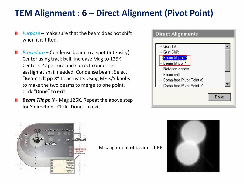
Purpose – make sure that the beam does not shift when it is tilted.
Procedure – Condense beam to a spot (Intensity). Center using track ball. Increase Mag to 125K. Center C2 aperture and correct condenser aastigmatism if needed. Condense beam. Select “Beam Tilt pp X” to activate. Using MF X/Y knobs to make the two beams to merge to one point. Click “Done” to exit.
Beam Tilt pp Y - Mag 125K. Repeat the above step for Y direction. Click “Done” to exit.
Misalignment of beam tilt PP

TEM Alignment : 7 – Focusing Binoculars
Purpose – the binoculars provide additional magnification so that fine features can be better viewed.
Procedure - Turn the outer knob of Beam Block towards you and insert the Beam Stop from Park position. Bring in Focusing Screen. Look at the Beam Stop on the Focusing Screen through the binoculars. Focus the Beam Block by adjusting the two focusing knobs on the binoculars. Attention: - not the Focus knob on RHP!
After finishing, return the Beam Block to park position by retracting and then turning the outer knob of the Beam Stop away from you. Lower the Focusing Screen.
Beam Block
Focusing knobs
Binoculars
Focusing screen lever

TEM Alignment : 8 – Direct Alignment (Rotation Center & Beam Shift)
Purpose – make sure that the beam is along the optical axis of the objective lens.
Beam shift - Mag 125K. Condense beam to a spot. Click “Beam Shift” to activate. If the beam is away from screen center, center it using MF X/Y. If the beam becomes invisible, reduce magnification to find the beam and then bring it to screen center by using MF X/Y. Click “Done” to exit.
Rotation Center – Mag 175K or above. Spread beam to cover screen. Correct condenser astigmatism if needed. Find a sharp feature and move it to screen center using joystick. Lift up Focusing Screen and watch the feature at screen center through binoculars. Click “Rotation Center”. Minimize the image shift of the central feature using the two “Multifunction knobs”. The image should pop up like “heart beat” but does not shift. For samples with no apparent sharp features, condense beam to a point, center the beam and minimize beam shift using MF X/Y Click “Done” to exit.
Note - It is good practice to check Rotation Center regularly before taking a high resolution picture, especially when you have moved to another location on the specimen or have changed focus value more than 1 μm.

Take TEM Image Using CCD Camera
Choose the area of interest and move it to screen center.
Focus specimen and spread beam. Never view a strong condensed beam using CCD.
You may use BM-Ultrascan to take regular TEM images. Click “Search” to start viewing samples on CCD.
“Search” with binning 4 and integration 0.07-0.1 sec.
“Preview” with binning 2 and 0.5-0.7 integration.
“Acquire” with binning 1 and integration 1-2 sec.
Save image to .emi format. Right click on the image and
export data as image format (.tiff, .jpeg, etc.)

Correct Objective Stigmation
There are two ways to correct Objective Stigmation.
1. Caustic curve – Focus image. Condense beam to a spot. Reduce “Z” so that a halo forms around the central bright spot. Go to “Tune”, click on “Objective” from the Stigmator menu. ” Adjust “MF x/y” to make the boundary of the halo round. This method is easy to perform but less accurate than the following FFT method.
2. Fast Fourier Transform (FFT) – Magnification 125k or above. Find and center an amorphous area. Acquire a live view in slow CCD (see next section for imaging with CCD camera). Click “Live FFT” in Camera menu to obtain a FFT image. Click on “Objective” from the Stigmator menu. ” Adjust “MF x/y” to make the FFT round.
Astigmatic Stigmation corrected

Focusing in TEM
Before focusing: (i) make sure eucentric height has been correctly set up. (ii) click “Eucentric Focus” on RHP. (iii) make sure C2 aperture is properly centered.
Besides making features sharp, there are three ways to assist focusing.
1) Minimum Contrast. (recommended) For all magnification. Look at image carefully. Focusing is achieved when the image has minimum contrast.
2) Fresnel Fringe. For all magnifications, look for particles, hole or edge area of the sample. Sample is out of focus if there is white (under-focus) or dark (over-focus) fringe around the edge. Adjust focus to minimize the fringe.
3) FFT. Preferred for high magnifications (>125k). Click “Live FFT” in Camera menu to obtain FFT image. Correct Obj. Stigmation. Turn Focus knob to maximize the diameter of the inner circle of FFT.
In-focus; minimum contrast
Note – use “Z-height” for rough focus and “Focus” knob for fine focus.
Out-of-focus; strong contrast

Figs. (a) under focus with objective astigmatism; (b) FFT for (a); (c) in focus with objective astigmatism; (d) FFT for (c); (e) over focus with objective astigmatism; (f) FFT for (e); (g) in focus without objective astigmatism; (h) FFT for (g).
Example of Focus and Astigmatism

Finishing Procedure
Click “Col. Valves Closed” button (color changes to yellow) to close column valves. Always close the column valve before inserting/removing the specimen holder!!
Switch back to TEM-Imaging mode (if you are using STEM or Diffraction).
Go to “Search”, click “Holder” button to reset the holder’s xyz and tilt angles to zero. (This is very important step. Failure to do so, the sample holder could be damaged during taking out).
Ask staff to help take out the holder.
Fill in the log sheet (time, the vacuum values and the emission value).
Top Related