


Languages
Pages
Legal


Lecture #5
In this lecture we will introduce the sequential circuits.
We will overview various Latches and Flip Flops (30 min)
Give Sequential Circuits design concept
Go over several examples as time permits
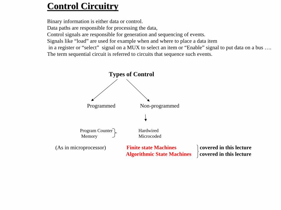
Control Circuitry Control Circuitry Binary information is either data or control.Data paths are responsible for processing the data,Control signals are responsible for generation and sequencing of events. Signals like “load” are used for example when and where to place a data itemin a register or “select” signal on a MUX to select an item or “Enable” signal to put data on a bus ….The term sequential circuit is referred to circuits that sequence such events.
Types of Control
Programmed Non-programmed
Program Counter HardwiredMemory Microcoded
(As in microprocessor) Finite state Machines covered in this lectureAlgorithmic State Machines covered in this lecture
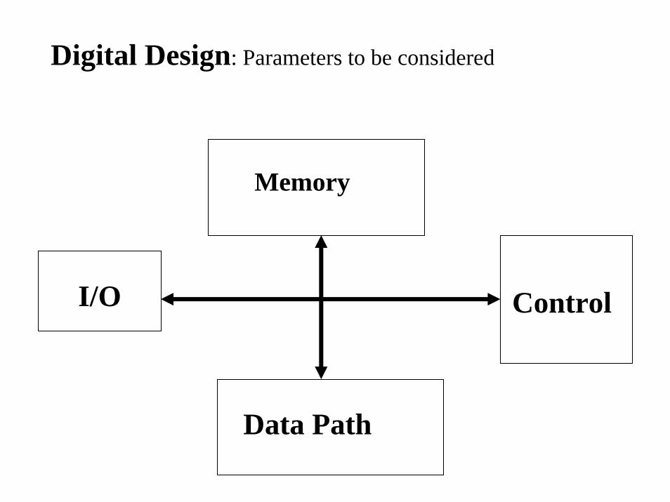
Memory
Data Path
ControlI/O
Digital Design: Parameters to be considered
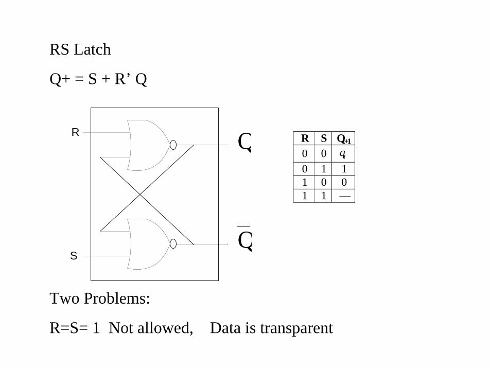
R S Qt+1 0 0 tq 0 1 1 1 0 0 1 1 —
R
SQ
Q
RS Latch
Q+ = S + R’ Q
Two Problems:
R=S= 1 Not allowed, Data is transparent

Q
D
C
Q
QC
D
RS Flip Flop
The D Latch
Problem: Level sensitive

QKQJQ 1t tt+=+
JK Flip Flop:
S
R
J
K
Q
Q
C
J
K
J
K
Q
Q
JK FFJ
K
Q
Q
C
JK Flip Flop with a rising-edge :
JK Latch : Universal, Level sensitive, Timing Constraints due to feed back. Other latches can be constructed using JK Latch
DLatch
DLatch
Q
QD
C
QD
C
D
C
Q
Master Slave
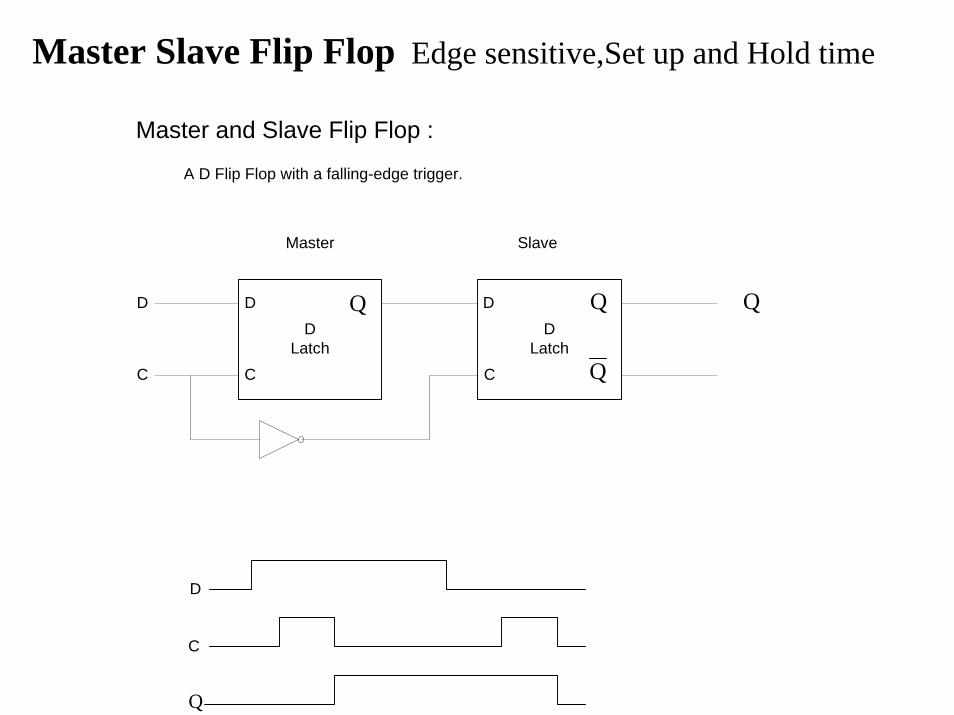
Master and Slave Flip Flop :
A D Flip Flop with a falling-edge trigger.
Q
D
C
Master Slave Flip Flop Edge sensitive,Set up and Hold time

S
R
Clk
Q
Q
`
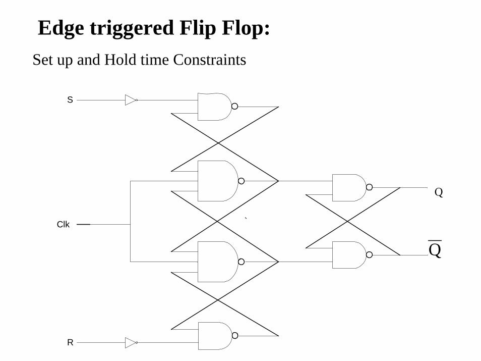
Edge triggered Flip Flop:Set up and Hold time Constraints

Combinational Logic
Memory
Input
Output
Excitation VectorsStates
Example 1Design a sequence detector that detects a sequence of 2 zeros or 3 ones on an incoming serial data line. Assume an asynchronous reset that initializes the machine.Let input be x, and output be z.

Example 2When a minor road crosses a highway a traffic controller is installed to control the flow of traffic. Normally the highway is given the right of way and where is a demand on the minor road then the highway is interrupted to give access to the minor road. You are asked to design controller to work on this principals.The highway should be given the right of way. If any of the sensors on the minor road do not detect presence of a car or if the sensor does detect a car but an amount of time equal to or greater than Timer long=T30 seconds, has not elapsed since last change. If there was a car on the minor road and amount of time greater than Timer long has elapsed, then the traffic light should cycle through amber for Timer short=3 seconds and change to Red, while minor road changes to Green. The minor road now should have access of the road while there is car but never more than Timer long. The minor road then should cycle back to red through a Timer short=3 second. While the highway cycles back to green
Minor RoadSensor
Highway
Sensor
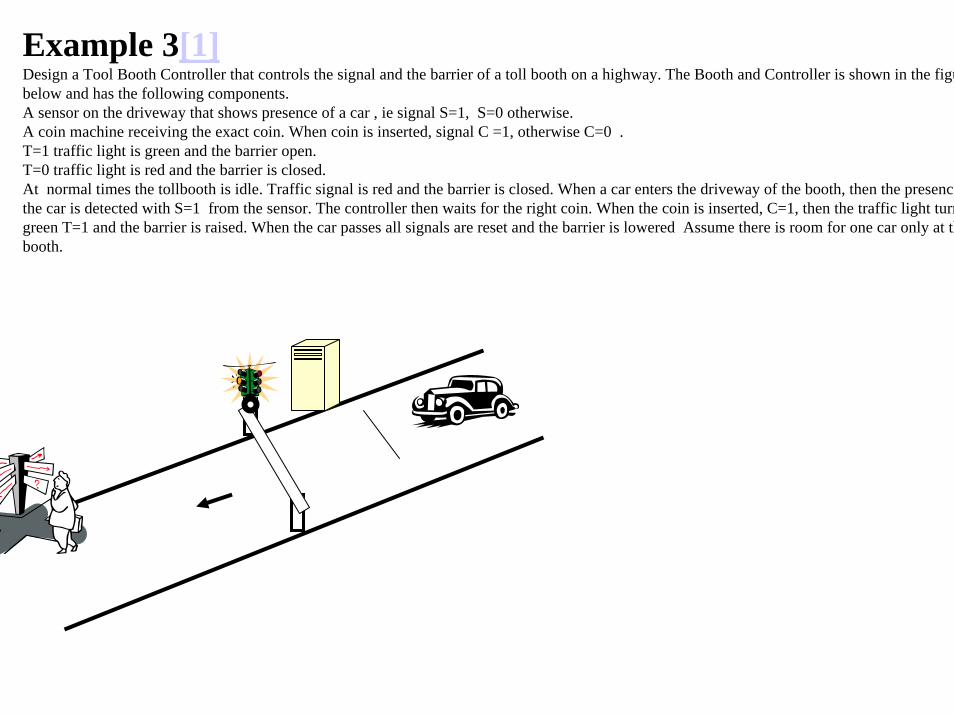
Example 3[1]Design a Tool Booth Controller that controls the signal and the barrier of a toll booth on a highway. The Booth and Controller is shown in the figubelow and has the following components.A sensor on the driveway that shows presence of a car , ie signal S=1, S=0 otherwise.A coin machine receiving the exact coin. When coin is inserted, signal C =1, otherwise C=0 .T=1 traffic light is green and the barrier open.T=0 traffic light is red and the barrier is closed.At normal times the tollbooth is idle. Traffic signal is red and the barrier is closed. When a car enters the driveway of the booth, then the presencethe car is detected with S=1 from the sensor. The controller then waits for the right coin. When the coin is inserted, C=1, then the traffic light turngreen T=1 and the barrier is raised. When the car passes all signals are reset and the barrier is lowered Assume there is room for one car only at thbooth.
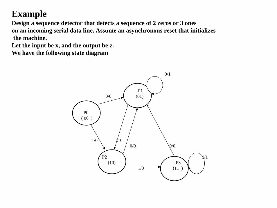
ExampleDesign a sequence detector that detects a sequence of 2 zeros or 3 oneson an incoming serial data line. Assume an asynchronous reset that initializesthe machine.
Let the input be x, and the output be z.We have the following state diagram
0/1
P10/0 (01)
P0( 00 )
1/0 1/00/0 0/0
P2 1/1(10) P3
1/0 (11 )
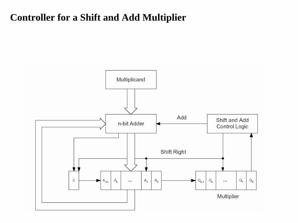
Controller for a Shift and Add Multiplier
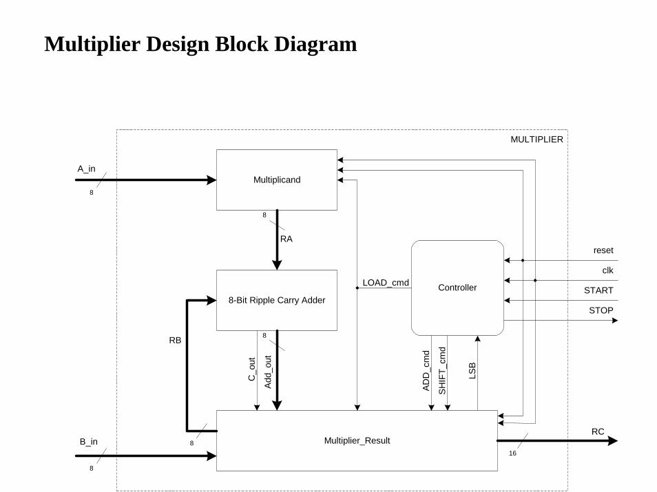
8-Bit Ripple Carry AdderController
8
reset
clk
START
STOP
A_in
B_inRC
Multiplier_Result
Multiplicand
8
16
RA
RB
8
8
8
Add
_out
C_o
ut
LSB
LOAD_cmd
MULTIPLIER
SH
IFT_
cmd
AD
D_c
md
Multiplier Design Block Diagram
IDLE
STOP = 1
INITLOAD_cmd=1
TEST
ADDADD_cmd = 1
SHIFTSHIFT_cmd =1count=count+1
START = 0
START = 1
LSB = 0
LSB = 1
count /= 8
count = 8
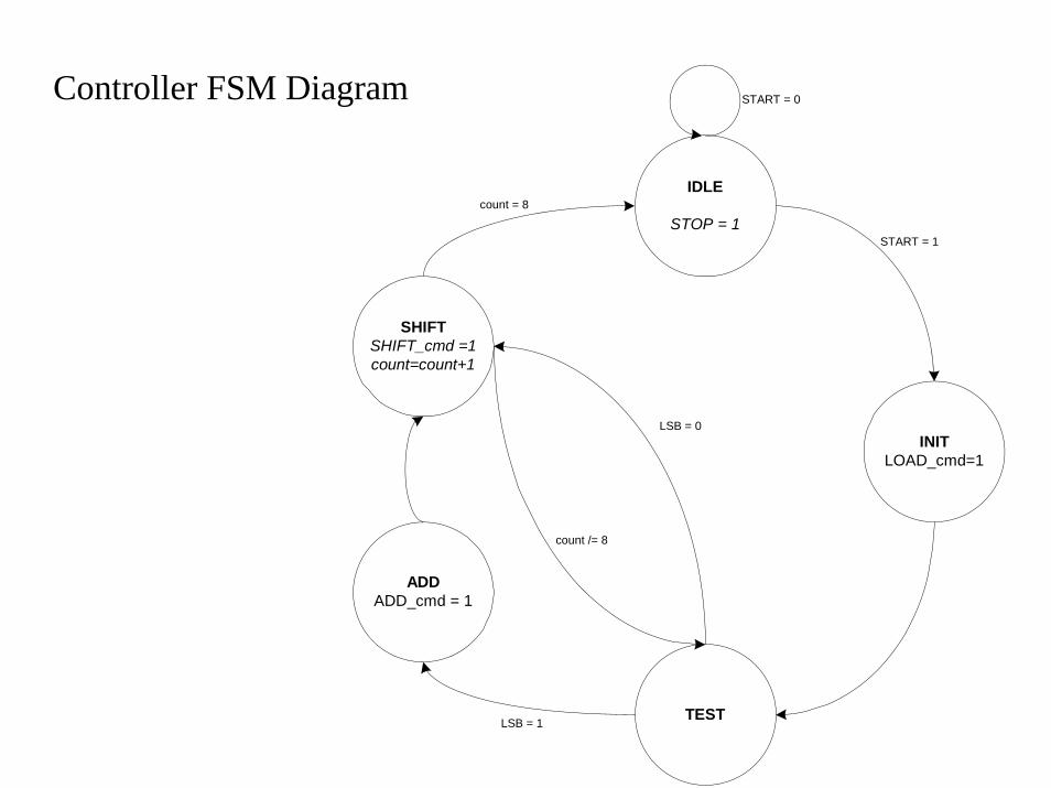
Controller FSM Diagram
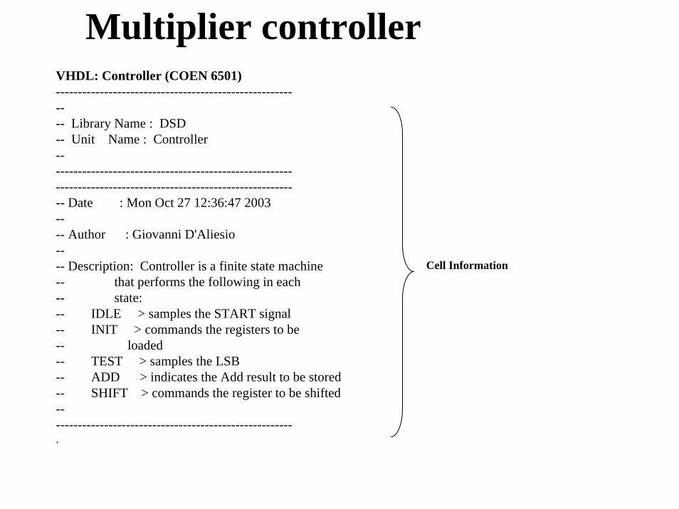
VHDL: Controller (COEN 6501)---------------------------------------------------------- Library Name : DSD-- Unit Name : Controller---------------------------------------------------------------------------------------------------------------- Date : Mon Oct 27 12:36:47 2003---- Author : Giovanni D'Aliesio---- Description: Controller is a finite state machine-- that performs the following in each-- state:-- IDLE > samples the START signal-- INIT > commands the registers to be-- loaded-- TEST > samples the LSB-- ADD > indicates the Add result to be stored-- SHIFT > commands the register to be shifted--------------------------------------------------------.
Multiplier controller
Cell Information
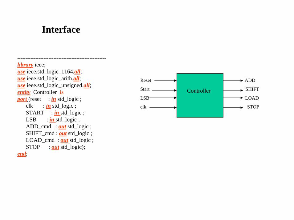
------------------------------------------------------library ieee;use ieee.std_logic_1164.all;use ieee.std_logic_arith.all;use ieee.std_logic_unsigned.all;entity Controller isport (reset : in std_logic ;
clk : in std_logic ;START : in std_logic ;LSB : in std_logic ;ADD_cmd : out std_logic ;SHIFT_cmd : out std_logic ;LOAD_cmd : out std_logic ;STOP : out std_logic);
end;
Reset ADD
Start SHIFT
LSB LOAD
clk STOP
Controller
Interface
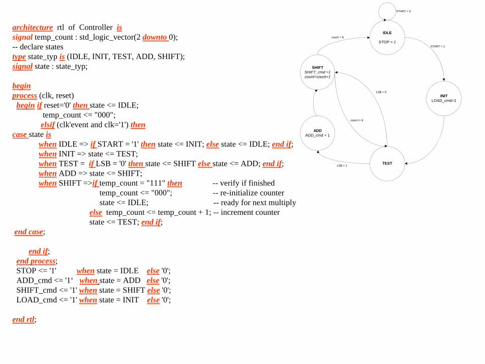
architecture rtl of Controller issignal temp_count : std_logic_vector(2 downto 0);-- declare states type state_typ is (IDLE, INIT, TEST, ADD, SHIFT);signal state : state_typ;
beginprocess (clk, reset)begin if reset='0' then state <= IDLE;
temp_count <= "000";elsif (clk'event and clk='1') then
case state iswhen IDLE => if START = '1' then state <= INIT; else state <= IDLE; end if;when INIT => state <= TEST; when TEST = if LSB = '0' then state <= SHIFT else state <= ADD; end if;when ADD => state <= SHIFT;when SHIFT =>if temp_count = "111" then -- verify if finished
temp_count <= "000"; -- re-initialize counterstate <= IDLE; -- ready for next multiply
else temp_count <= temp_count + 1; -- increment counterstate <= TEST; end if;
end case;
end if;end process;STOP <= '1' when state = IDLE else '0';ADD_cmd <= '1‘ when state = ADD else '0';SHIFT_cmd <= '1' when state = SHIFT else '0';LOAD_cmd <= '1' when state = INIT else '0';
end rtl;
IDLE
STOP = 1
INITLOAD_cmd=1
TEST
ADDADD_cmd = 1
SHIFTSHIFT_cmd =1count=count+1
START = 0
START = 1
LSB = 0
LSB = 1
count /= 8
count = 8
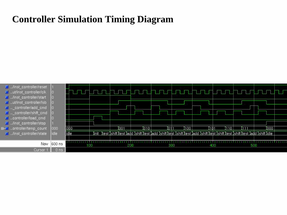
Controller Simulation Timing Diagram
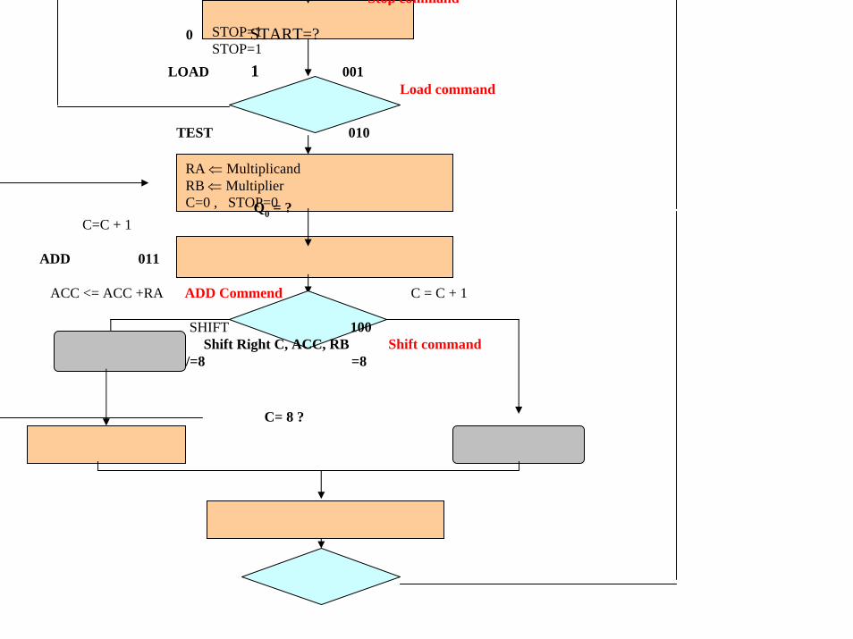
STOP=1STOP=1
RA ⇐ MultiplicandRB ⇐ MultiplierC=0 , STOP=0
Stop command
0 START=?
LOAD 1 001Load command
TEST 010
Q0 = ?C=C + 1
ADD 011
ACC <= ACC +RA ADD Commend C = C + 1
SHIFT 100Shift Right C, ACC, RB Shift command
/=8 =8
C= 8 ?


Top Related