


Languages
Pages
Legal

Digital auDio Processor
FM- 25
600 Industrial Drive, New Bern, North Carolina 28562 (tel 252-638-7000 / fax 252-637-1285 )
Technical
Manual
Technical
Manual
Wheatstone CorporationMay 2015
Digital auDio Processor
FM- 25
600 Industrial DriveNew Bern, North Carolina 28562tel 252-638-7000 / fax 252-637-1285
Wheatstone Digital Augio Processor Technical Manual
©2015 Wheatstone Corporation. All Rights Reserved
FM-25 / May 2015
U lt r a - H i g H r e s o l U t i o n P r o c e s s i n gORSIS
No part of this manual may be copied, sold or re-printed without express written consent of Wheatstone Corporation. All images and text are the property of
Wheatstone Corporation and are included as an aide to installation and operation of the product by the intended owner.
All images and described features contained within this manual are subject to change based on product improvement. Please feel free to contact technical support at 252-638-7000 or at [email protected] should you have any questions.
Read Me!FM-25 / June 2015
Attention!Attention!
Federal Communications Commission (FCC) Compliance Notice:Radio Frequency Notice
NOTE: This equipment has been tested and found to comply with the limits for a Class A digital device, pursuant to Part 15 of the FCC rules. These limits are designed to provide reasonable protection against harmful interference when the equipment is operated in a commercial environment. This equipment generates, uses, and can radiate radio frequency energy and, if not installed and used in accordance with the instruction manual, may cause harmful interference to radio communications. Operation of this equipment in a residential area is likely to cause harmful interference in which case the user will be required to correct the interference at his own expense.
This is a Class A product. In a domestic environment, this product may cause radio interference, in which case, the user may be required to take appropriate measures.
This equipment must be installed and wired properly in order to assure compliance with FCC regulations.
Caution! Any modifications not expressly approved in writing by Wheatstone could void the user's authority to operate this equipment.
IntroductIon - 1FM-25 / May 2015
The History of Wheatstone Audio Processors
Introduced in 2005, the Vorsis product line evolved from Wheatstone’s return to its original roots in audio processing. Having designed and integrated analog and then, later, complex digital audio processing into our radio and television consoles and control surfaces, Wheatstone was perfectly poised to address the challenges of combining very high audio quality with competitive on air loudness.
Wheatstone audio processors are built to the same exacting standards as all Wheatstone products. Research and development, manufacturing, testing, and qual‑ity control for the line of audio processors are all accomplished within Wheatstone’s large state‑of‑the‑art facility located in New Bern, North Carolina. Keeping everything under one roof allows Wheatstone to have control over every facet of production and ensures that our costumers receive products of the highest possible quality and reliability. Staying true to “Made in the USA,” Wheatstone does not utilize offshore manufacturing.
A dozen experts with deep experience in Digital Signal Processing, broadcast audio and other engineering disciplines comprise our design team. Led by audio processing expert and broadcast engineering veteran Jeff Keith, the team combines their talents to design and build audio processors that achieve the highest standards of on ‑air sound quality.
In its short history Wheatstone Processing has already invented many new and unique audio processing algorithms – algorithms that push audio processor performance to new and higher levels. Wheatstone was the first to develop an intelligent, “program density aware” AGC (2007 - Sweet Spot Technology, or SST). We were also the first to employ the science of human psychoacoustics in the design of a multiband limiter (2005, our acclaimed and patented 31‑band limiter). In addition, our well‑regarded Bass Management systems solve the bass intermodulation problems that plague other brands of audio processors when pushed for competitive loudness.
Each Wheatstone Processing product comes with its own Windows® software‑based intuitive Graphical User Interface for control of the processor. Carefully tuned factory presets ensure that our audio processors can be placed into use quickly and easily in any size market with a minimum of effort.
ORSIS Ultra-HigH resolUtion Processing
page Contents – 1FM-25 / May 2015
C O N T E N T S
FM-25 Technical Manual
Chapter 1 - General Information
Table of Contents
Introduction ....................................................................................1-2
FM-25 Feature Overview ...............................................................1-3
Rack Mounting ...............................................................................1-3FM-25 Installation Tips ...............................................................................................1-5
Grounding ...............................................................................................................1-5
Surge Protection .....................................................................................................1-5
UPS/Power Conditioning ........................................................................................1-5
Analog Audio Input Connections ............................................................................1-5
Analog Audio Output Connections .........................................................................1-6
Digital Audio/baseband192 Connections ................................................................1-6
Where to Install the FM-25 .........................................................................................1-7
Digital STL ..............................................................................................................1-7
Analog Left/Right STL ............................................................................................1-8
Composite Analog STL ...........................................................................................1-8
Analog Phone Lines ...............................................................................................1-8
Where Should Pre-Emphasis Go? .........................................................................1-9
Ratings Encoders ...................................................................................................1-9
AC Power Considerations ............................................................1-9
Rear Panel Connections ..............................................................1-10Audio Inputs ...............................................................................................................1-10
Analog In ................................................................................................................1-11
AES In ....................................................................................................................1-11
SCA In ....................................................................................................................1-11
FM Audio Outputs ......................................................................................................1-11
Analog Out ..............................................................................................................1-11
AES/baseband192 Out ...........................................................................................1-11
TX Out ....................................................................................................................1-12
Headphone Monitoring ..............................................................................................1-12
Network Connection ..................................................................................................1-12
Ethernet RJ-45 .......................................................................................................1-12
Typical Straight-Through Cable ..............................................................................1-12
Typical Crossover Cable ........................................................................................1-13
Processing Presets ....................................................................................................1-14
FM-25 Input/Output Connections Drawing ................................................................1-15
page Contents – 2FM-25 / May 2015
C O N T E N T S
Meters .............................................................................................2-2
OLED Display .................................................................................2-2Headphone .................................................................................................................2-4
Source Selection .....................................................................................................2-4
Headphone Volume .................................................................................................2-4
Presets .......................................................................................................................2-4
Input............................................................................................................................2-4
Input Source ............................................................................................................2-4
Input Gain Adjustment .............................................................................................2-5
Pre-Emphasis .............................................................................................................2-5
Sound .........................................................................................................................2-5
Texture ....................................................................................................................2-5
EQ ...........................................................................................................................2-6
Save ........................................................................................................................2-6
A Note About The Front Panel Sound Adjustments ................................................2-6
Output .........................................................................................................................2-7
Network ......................................................................................................................2-8
Changing The Network Settings .............................................................................2-8
Leading Zeroes ........................................................................................................2-8
Default IP Address ...................................................................................................2-8
Vesions .......................................................................................................................2-8
Access ........................................................................................................................2-9
Getting Started ...............................................................................3-4
Connecting With the GUI ..............................................................3-5
Configuring the GUI ......................................................................3-5Connecting Directly Without a LAN ............................................................................3-5
The FM-25 and Internet Security Concerns ...............................................................3-6
About DHCP and the FM-25 .......................................................................................3-6
The FM-25 Network Protocols and Ports Used ..........................................................3-6
Using the FM-25 GUI .....................................................................3-7Dynamic Displays Region ...........................................................................................3-8
Frequency-Domain Graph .......................................................................................3-8
Managing the Blue Dots - Tutorial ...........................................................................3-8
Control Area Region ..................................................................................................3-10
Input Menu ..............................................................................................................3-11
Input Source .......................................................................................................3-11
Input Signal Presence ........................................................................................3-11
Analog Input Gain ...............................................................................................3-12
Digital Input Gain ................................................................................................3-12
L/R Balance ........................................................................................................3-12
Phase Rotator .....................................................................................................3-12
HPF - High Pass Filter ........................................................................................3-13
Metering ..............................................................................................................3-13
Chapter 2 - FM-25 Front Panel
Chapter 3 - FM-25 PC GUI
page Contents – 3FM-25 / May 2015
C O N T E N T S
Multiband AGC Menu .............................................................................................3-14
A Word About Outboard Processors and Rreeveettbb .......................................3-16
Multibang AGC Controls .....................................................................................3-16
MB Compressor ..............................................................................................3-16
MB Leveller .....................................................................................................3-16
iAGC ...............................................................................................................3-16
RTZ Enable ....................................................................................................3-16
AGC Drive ......................................................................................................3-17
Gate Delay ......................................................................................................3-17
Gate Mode ......................................................................................................3-17
Gate Threshold ...............................................................................................3-17
Bass G/R Offset ..............................................................................................3-17
Stereo Enchance ............................................................................................3-17
Multiband AGC Dynamic Displays Menu ............................................................3-18
Threshold ........................................................................................................3-18
Attack ..............................................................................................................3-18
Release ..........................................................................................................3-19
FM Limiter Menu .....................................................................................................3-20
EQ, Limiter and Clippers Controls ......................................................................3-20
Pre-Emphasis .................................................................................................3-20
Limiter Drive ...................................................................................................3-20
Bass Enchance ...............................................................................................3-21
Enable ............................................................................................................3-21
Clipper Drive ...................................................................................................3-21
EQ LF/HF Shelf ..............................................................................................3-21
Limiters and Clippers Dynamic Displays Menu ..................................................3-22
Threshold ........................................................................................................3-22
Attack ..............................................................................................................3-22
Release ..........................................................................................................3-22
Stereo Generator Menu ..........................................................................................3-23
Mode ...................................................................................................................3-23
Composite Clipper Drive .....................................................................................3-23
Pilot Injection ......................................................................................................3-23
Multipath Limiter ................................................................................................3-23
SCA Level ...........................................................................................................3-24
Analog Output ....................................................................................................3-25
De-Emphasis ..................................................................................................3-25
PreDelay .........................................................................................................3-25
Digital Output .....................................................................................................3-25
Baseband192 and AES Modes ......................................................................3-25
De-Emphasis ..................................................................................................3-26
Sample Rate ...................................................................................................3-26
MPX Outputs ......................................................................................................3-26
System Menu ..........................................................................................................3-27
Input/Output Settings Change With Preset .........................................................3-27
Metering Data Over TCP/IP ................................................................................3-28
System Status ....................................................................................................3-28
Remote Login .....................................................................................................3-28
Front Panel .........................................................................................................3-29
GUI Access .........................................................................................................3-30
GUI Lock .............................................................................................................3-30
page Contents – 4FM-25 / May 2015
C O N T E N T S
Side Bar Region ........................................................................................................3-31
Preset .....................................................................................................................3-31
Library .....................................................................................................................3-31
Locking Presets ..................................................................................................3-32
How to View Preset Changes .............................................................................3-32
Save .......................................................................................................................3-33
Devices ...................................................................................................................3-33
Headphone Control ................................................................................................3-33
Headphone Source .................................................................................................3-33
Title Bar Region .........................................................................................................3-34
Status .....................................................................................................................3-34
Device .....................................................................................................................3-34
Current Preset ........................................................................................................3-34
Notes on Online and Offline Working .....................................................................3-35
Accessing Menu Options ...........................................................................................3-36
File Menu Items ......................................................................................................3-36
Hardware Menu Items ............................................................................................3-36
FM-25 Hardware Update ....................................................................................3-36
Preset Menu Items .................................................................................................3-38
General Specifications ..................................................................A-3
Interpreting Common Audio Processing Terms .........................A-8Background ................................................................................................................A-8
Audio Terms and Wheatstone Processing .................................................................A-9
Thump/Rumble/Bottom ............................................................................................A-9
Punch/Boom/Tubby/Warm .....................................................................................A-10
Mud .........................................................................................................................A-10
Honk .......................................................................................................................A-10
Whack .....................................................................................................................A-10
Fuzzy/Tinny ............................................................................................................A-11
Sibilance .................................................................................................................A-11
Treble/Bright/Open .................................................................................................A-11
Finally .....................................................................................................................A-12
WheatNet-IP Configuration ..........................................................A-14Adding FM-25 to The WheatNet-IP System ..............................................................A-14
Appendix B
Appendix C
Appendices
Appendix A
page 1 – 1FM-25 / May 2015
G E N E R A L I N F O R M A T I O N
General Information
Introduction ....................................................................................1-2
FM-25 Feature Overview ...............................................................1-3
Rack Mounting ...............................................................................1-3FM-25 Installation Tips ...............................................................................................1-5
Grounding ...............................................................................................................1-5
Surge Protection .....................................................................................................1-5
UPS/Power Conditioning .......................................................................................1-5
Analog Audio Input Connections............................................................................1-5
Analog Audio Output Connections .........................................................................1-6
Digital Audio/baseband192 Connections ...............................................................1-6
Where to Install the FM-25 .........................................................................................1-7
Digital STL ..............................................................................................................1-7
Analog Left/Right STL ............................................................................................1-8
Composite Analog STL ..........................................................................................1-8
Analog Phone Lines ...............................................................................................1-8
Where Should Pre-Emphasis Go? ..........................................................................1-9
Ratings Encoders ...................................................................................................1-9
AC Power Considerations ............................................................1-9
Rear Panel Connections ..............................................................1-10Audio Inputs ..............................................................................................................1-10
Analog In ................................................................................................................1-11
AES In .....................................................................................................................1-11
SCA In ....................................................................................................................1-11
FM Audio Outputs .....................................................................................................1-11
Analog Out .............................................................................................................1-11
AES/baseband192 Out ...........................................................................................1-11
TX Out ....................................................................................................................1-12
Headphone Monitoring ..............................................................................................1-12
Network Connection .................................................................................................1-12
Ethernet RJ-45 .......................................................................................................1-12
Typical Straight-Through Cable ..............................................................................1-12
Typical Crossover Cable .........................................................................................1-13
Processing Presets ....................................................................................................1-14
FM-25 Input/Output Connections Drawing ...............................................................1-15
Chapter Contents
page 1 – 2FM-25 / May 2015
G E N E R A L I N F O R M A T I O N
General InformationIntroduction
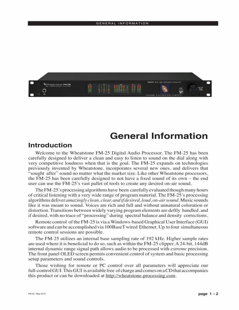
Welcome to the Wheatstone FM‑25 Digital Audio Processor. The FM‑25 has been carefully designed to deliver a clean and easy to listen to sound on the dial along with very competitive loudness when that is the goal. The FM‑25 expands on technologies previously invented by Wheatstone, incorporates several new ones, and delivers that “sought after” sound no matter what the market size. Like other Wheatstone processors, the FM‑25 has been carefully designed to not have a fixed sound of its own – the end user can use the FM‑25’s vast pallet of tools to create any desired on‑air sound.
The FM‑25’s processing algorithms have been carefully evaluated though many hours of critical listening with a very wide range of program material. The FM‑25’s processing algorithms deliver amazingly clean, clear, and if desired, loud, on-air sound. Music sounds like it was meant to sound. Voices are rich and full and without unnatural coloration or distortion. Transitions between widely varying program elements are deftly handled, and if desired, with no trace of “processing” during spectral balance and density corrections.
Remote control of the FM‑25 is via a Windows‑based Graphical User Interface (GUI) software and can be accomplished via 100BaseT wired Ethernet. Up to four simultaneous remote control sessions are possible.
The FM‑25 utilizes an internal base sampling rate of 192 kHz. Higher sample rates are used where it is beneficial to do so, such as within the FM‑25 clipper. A 24‑bit, 144dB internal dynamic range signal path allows audio to be processed with extreme precision. The front panel OLED screen permits convenient control of system and basic processing setup parameters and sound controls.
Those wishing for remote or PC control over all parameters will appreciate our full‑control GUI. This GUI is available free of charge and comes on a CD that accompanies this product or can be downloaded at http://wheatstone‑processing.com.
page 1 – 3FM-25 / May 2015
G E N E R A L I N F O R M A T I O N
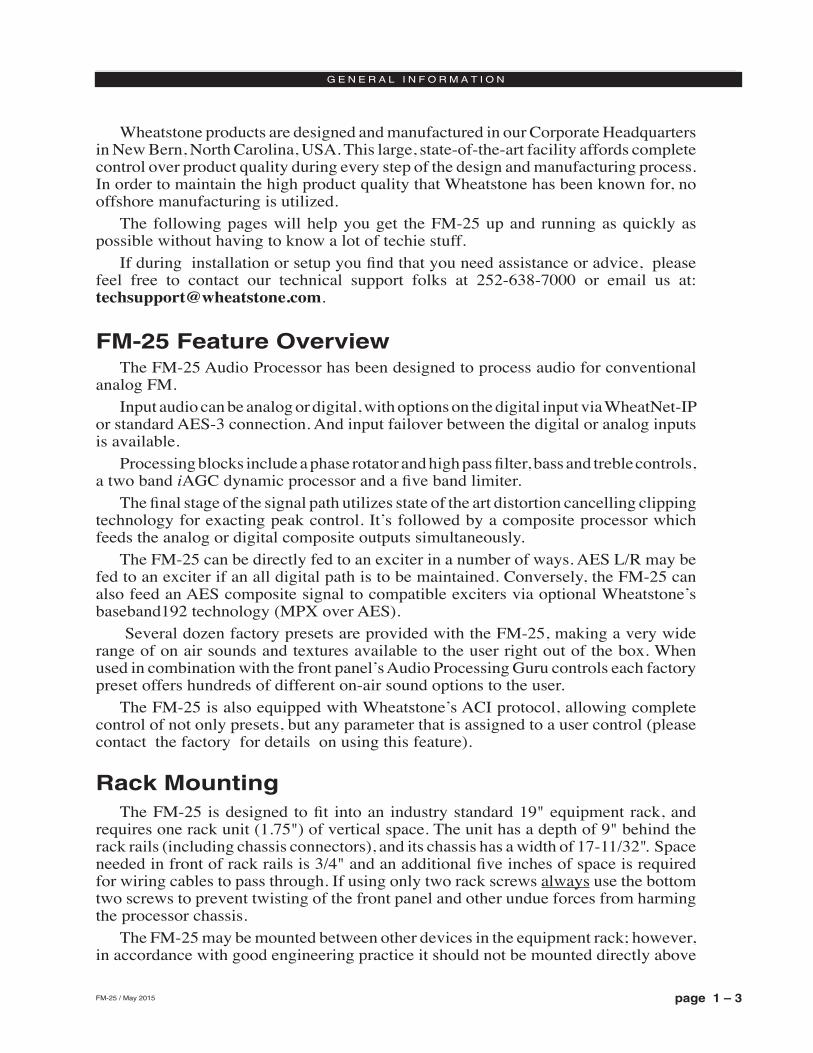
Wheatstone products are designed and manufactured in our Corporate Headquarters in New Bern, North Carolina, USA. This large, state‑of‑the‑art facility affords complete control over product quality during every step of the design and manufacturing process. In order to maintain the high product quality that Wheatstone has been known for, no offshore manufacturing is utilized.
The following pages will help you get the FM‑25 up and running as quickly as possible without having to know a lot of techie stuff.
If during installation or setup you find that you need assistance or advice, please feel free to contact our technical support folks at 252‑638‑7000 or email us at: [email protected].
FM-25 Feature OverviewThe FM‑25 Audio Processor has been designed to process audio for conventional
analog FM. Input audio can be analog or digital, with options on the digital input via WheatNet‑IP
or standard AES‑3 connection. And input failover between the digital or analog inputs is available.
Processing blocks include a phase rotator and high pass filter, bass and treble controls, a two band iAGC dynamic processor and a five band limiter.
The final stage of the signal path utilizes state of the art distortion cancelling clipping technology for exacting peak control. It’s followed by a composite processor which feeds the analog or digital composite outputs simultaneously.
The FM‑25 can be directly fed to an exciter in a number of ways. AES L/R may be fed to an exciter if an all digital path is to be maintained. Conversely, the FM‑25 can also feed an AES composite signal to compatible exciters via optional Wheatstone’s baseband192 technology (MPX over AES).
Several dozen factory presets are provided with the FM‑25, making a very wide range of on air sounds and textures available to the user right out of the box. When used in combination with the front panel’s Audio Processing Guru controls each factory preset offers hundreds of different on‑air sound options to the user.
The FM‑25 is also equipped with Wheatstone’s ACI protocol, allowing complete control of not only presets, but any parameter that is assigned to a user control (please contact the factory for details on using this feature).
Rack MountingThe FM‑25 is designed to fit into an industry standard 19" equipment rack, and
requires one rack unit (1.75") of vertical space. The unit has a depth of 9" behind the rack rails (including chassis connectors), and its chassis has a width of 17‑11/32". Space needed in front of rack rails is 3/4" and an additional five inches of space is required for wiring cables to pass through. If using only two rack screws always use the bottom two screws to prevent twisting of the front panel and other undue forces from harming the processor chassis.
The FM‑25 may be mounted between other devices in the equipment rack; however, in accordance with good engineering practice it should not be mounted directly above
page 1 – 4FM-25 / May 2015
G E N E R A L I N F O R M A T I O N
devices that generate a significant amount of heat (such as power amplifiers or power supplies). If such a location is unavoidable, then it is advisable to utilize an extra 1RU blank rack panel between the FM‑25 and devices imm ediately above and/or below it.
WARNING!With very few exceptions, the FM-25 chassis DOES NOT need to be opened in the
field. Please be advised that the FM-25 contains high voltage power supply circuits
operating at voltages well above AC line input. These voltages are hazardous and potentially deadly if accidentally contacted.
Special tools, software, and fixtures are required for service. There are no user‑serviceable parts inside.
The FM-25 unit must be returned to Wheatstone Corporation under a Return Authorization in the unlikely event that repair is necessary.
If you need to return the FM‑25 to Wheatstone for repair, please contact our office at 252-638-7000 Monday – Friday 8:30am to
5:30pm ET or after hours at [email protected] for a Return Authorization (RA) number.
page 1 – 5FM-25 / May 2015
G E N E R A L I N F O R M A T I O N
FM-25 Installation Tips
Grounding Establish a low impedance common ground in the facility and try to route all
equipment grounds to that point. Use ground conductors with the largest possible surface area and keep ground leads as short as possible. The FM‑25’s ground reference is its chassis, which should be connected to the station ground. Such a connection is especially important when the FM‑25 is operated in a high RF environment because it helps minimize differential voltages between the processor’s chassis and other pieces of equipment such as the rack it is mounted within.
Surge Protection Always place surge protection circuits as close as possible to the device being
protected. AC power line surge protection should manage transients in a way that keeps instantaneous potential differences between the power line hot, neutral, AC grounding conductor, the station ground, and the processor chassis as low as possible. Likewise, measures should also be taken to keep the instantaneous potential difference between the audio cable shields and the processor chassis as low as possible (this applies to all audio equipment, not just the FM‑25), particularly when the equipment is located within the electrically hostile environment of a station’s transmitter facility.
UPS/Power Conditioning Choose the best power conditioning/UPS units that your budget will allow, focusing
on the most important features and options that you actually need. Some questions to ask while reviewing features are:
‑ How does the UPS behave when AC power is not exactly 60Hz, such as when the facility is on its backup generator?
‑ If the UPS has onboard surge protection, what kind of surge capability does it have and where are those surges directed to?
‑ Is the UPS equipped with remote monitoring capability?‑ Does the UPS have onboard monitoring and alarms to signal problems such as
low batteries?
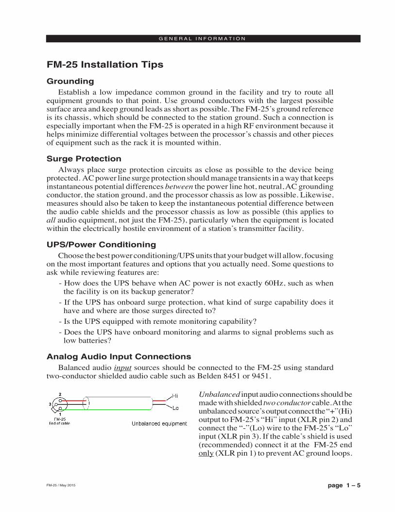
Analog Audio Input Connections Balanced audio input sources should be connected to the FM‑25 using standard
two‑conductor shielded audio cable such as Belden 8451 or 9451.
Unbalanced input audio connections should be made with shielded two conductor cable. At the unbalanced source’s output connect the “+”(Hi) output to FM‑25’s “Hi” input (XLR pin 2) and connect the “‑”(Lo) wire to the FM‑25’s “Lo” input (XLR pin 3). If the cable’s shield is used (recommended) connect it at the FM‑25 end only (XLR pin 1) to prevent AC ground loops.
page 1 – 6FM-25 / May 2015
G E N E R A L I N F O R M A T I O N
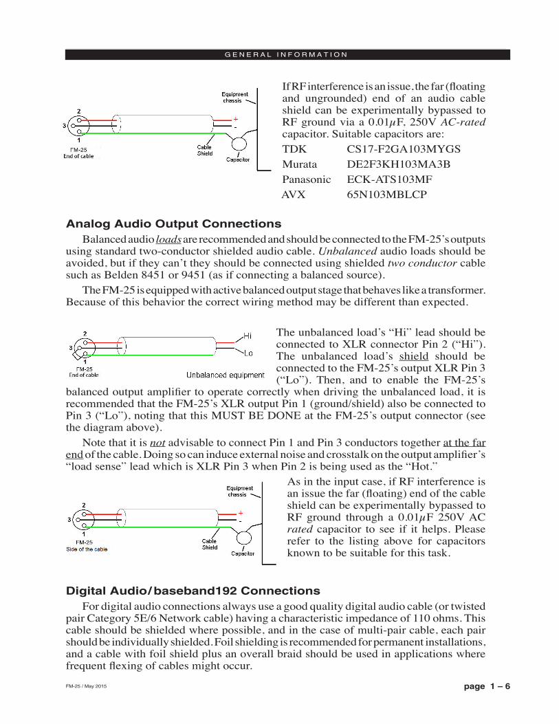
If RF interference is an issue, the far (floating and ungrounded) end of an audio cable shield can be experimentally bypassed to RF ground via a 0.01µF, 250V AC-rated capacitor. Suitable capacitors are: TDK CS17‑F2GA103MYGSMurata DE2F3KH103MA3BPanasonic ECK‑ATS103MFAVX 65N103MBLCP
Analog Audio Output ConnectionsBalanced audio loads are recommended and should be connected to the FM‑25’s outputs
using standard two‑conductor shielded audio cable. Unbalanced audio loads should be avoided, but if they can’t they should be connected using shielded two conductor cable such as Belden 8451 or 9451 (as if connecting a balanced source).
The FM‑25 is equipped with active balanced output stage that behaves like a transformer. Because of this behavior the correct wiring method may be different than expected.
The unbalanced load’s “Hi” lead should be connected to XLR connector Pin 2 (“Hi”). The unbalanced load’s shield should be connected to the FM‑25’s output XLR Pin 3 (“Lo”). Then, and to enable the FM‑25’s
balanced output amplifier to operate correctly when driving the unbalanced load, it is recommended that the FM‑25’s XLR output Pin 1 (ground/shield) also be connected to Pin 3 (“Lo”), noting that this MUST BE DONE at the FM‑25’s output connector (see the diagram above).
Note that it is not advisable to connect Pin 1 and Pin 3 conductors together at the far end of the cable. Doing so can induce external noise and crosstalk on the output amplifier’s “load sense” lead which is XLR Pin 3 when Pin 2 is being used as the “Hot.”
As in the input case, if RF interference is an issue the far (floating) end of the cable shield can be experimentally bypassed to RF ground through a 0.01µF 250V AC rated capacitor to see if it helps. Please refer to the listing above for capacitors known to be suitable for this task.
Digital Audio/ baseband192 Connections For digital audio connections always use a good quality digital audio cable (or twisted
pair Category 5E/6 Network cable) having a characteristic impedance of 110 ohms. This cable should be shielded where possible, and in the case of multi‑pair cable, each pair should be individually shielded. Foil shielding is recommended for permanent installations, and a cable with foil shield plus an overall braid should be used in applications where frequent flexing of cables might occur.
page 1 – 7FM-25 / May 2015
G E N E R A L I N F O R M A T I O N
Generic “audio” cable such as Belden 8451 and 9451 may sometimes be used for interconnecting AES3 digital audio devices as long as the cable is short. The actual cable length that will work satisfactorily is determined by many factors including the error correction and jitter tolerance of the AES3 receiver, the characteristics of the digital cable driver and the characteristics of the specific cable being used and its length. “Generic” analog audio cables usually have higher capacitance than digital cable and high capacitance cables can impair the ability of the AES3 receiver to recover the digital signal without errors. Increased jitter, dropouts, or no audio at all can be an indication of an improper cable type.
Where to Install the FM-25The best location to install the FM‑25 is at the transmitter site. This requires that
a discrete Left/Right STL, either analog or digital, be involved in the signal path. The major benefit of a transmitter site installation is that it enables the use of the FM‑25’s built‑in lab‑grade stereo encoder which allows much tighter control of modulation peaks.
A transmitter site location has the additional benefit of allowing the use of the FM‑25’s highly oversampled composite processor to gain an additional loudness advantage. The Wheatstone composite processor is much cleaner and more forgiving than those in other products, and in combination with the FM‑25’s tight pilot and SCA protection filters can create additional loudness without the audible grunge that composite clippers typically create.
With the advent of Wheatstone’s baseband192 technology, the promise of an all digital airchain that is as loud as its analog composite sibling is now a reality. Users now have the option of deploying the FM‑25 and other Wheatstone processors using traditional analog or MPX over AES with a compatible exciter.
We recommend that, whenever there is a choice between using an exciter’s composite MPX, AES over MPX option, or AES3 input, the processor (any processor) should be interfaced to the transmitter using the exciter’s AES over MPX or analog composite stereo multiplex input. The exciter’s AES3 digital input may be “clean” and it may be “digital,” but it also precludes the ability to gain additional loudness through the use of the FM‑25’s intelligent oversampled composite clipper. Also, depending on factors including the sample rates being used the exciter’s AES digital input can exhibit inferior peak control compared to the exciter’s composite input.
When the FM‑25 is located at the studio and an STL is being used to send the program material to the transmitter site there are several issues to consider:
Digital STLThere are two categories of Digital STL’s on the market – those with codec‑based
audio compression and those with uncompressed linear audio. When a digital STL employs codec‑based audio compression the FM‑25 should be
located at the transmitter site which places it after the codec. This is very important because most codecs will sound better when presented with unprocessed studio audio instead of highly processed and pre‑emphasized audio from the processor’s output. Further, the encoding schemes used in such STL’s cannot accurately pass the well‑defined peak levels created by the FM‑25, creating a modulation (loudness) disadvantage.
page 1 – 8FM-25 / May 2015
G E N E R A L I N F O R M A T I O N
Installing the FM‑25 at the studio end of a “compressed” STL brings with it at least two caveats:
‑ The FM‑25 stereo generator and composite clipper will not be available. Many digital exciters offer stereo generator and composite clipper functions, but their clippers have historically been quite crude and spectrally “dirty” compared to the FM‑25’s exceptional clipper. Therefore exciter hosted composite clippers are not the optimum choice when the station’s ultimate sound quality is important.
‑ Compressed STL’s do not perform well when presented with competitively processed audio, especially when that audio is pre‑emphasized. This is because codecs do their work by examining the audio for opportunities to remove content that shouldn’t be audible to the average human ear. When densely processed audio is presented to a codec, there are fewer opportunities to remove redundant audio information and then mask that removal from our hearing. When handling heavily processed (limited dynamic range) material codec operation can be much more obvious – even to the point of being objectionable – than when the processing is located after the codec where the masked artifacts are only occasionally and, usually, minimally unmasked by processing gain.
Uncompressed (linear) digital STL’s have only one major installation limitation – placing the FM‑25 at the studio end of the STL will preclude the use of the stereo generator and composite clipper.
TIP: If using the FM‑25 at the studio be certain that any clippers and emphasis in the stereo generator at the transmitter site are properly set up to complement the settings in FM‑25. This will prevent gross distortion and potentially large modulation overshoots.
Analog Left/Right STLOlder analog discrete left/right STL’s can suffer from an inability to control audio
peaks because of inadequate bandwidth in their IF circuits and/or poor low frequency and phase performance. Individual left/right STL’s rarely have identical group delay and this will adversely affect stereo separation when the signal is finally converted to the multiplex composite domain. Such STL’s can also suffer from AFC bounce when handling highly processed low frequency material, robbing modulation and reducing on‑air loudness.
Composite Analog STLA high quality analog composite STL can have advantages over an analog left/right
STL in that it will typically have broader audio bandwidth and better audio performance than discrete analog STL. Most also have the capability to add subcarriers for SCA and RDS along with the composite audio. This means that many SCA and RDS generators may be located at the studio end of the STL, which, along with the audio processor, makes for a very convenient setup. With a modern composite STL and properly engineered point‑to‑point path, the audio can be nearly as transparent as a digital STL.
Analog Phone LinesDiscrete left/right analog “phone line” STL’s are not recommended because of the
inability of most Telco service providers to meet the flat frequency response and phase matching requirements. Furthermore, in many countries wideband analog circuits have
page 1 – 9FM-25 / May 2015
G E N E R A L I N F O R M A T I O N
become unavailable or their cost prohibitive. On the other hand if the wired STL is a dedicated (and equalized if necessary) pair of circuits that is under the station’s full control it may be acceptable.
Where Should Pre-Emphasis Go?Pre‑emphasis should always be applied by the audio processing, and never by
the exciter. Modern FM audio processors are equipped with highly refined and very sophisticated technology to manage the myriad challenges posed by FM pre‑emphasis. They can provide very tight modulation control with very low perceived distortion. No FM exciters have this technology.
To summarize: the best location overall for the audio processor is always at the transmitter.
Ratings EncodersField experience has been that Wheatstone audio processors favorably pass the
data watermarking scheme used in the rating service technology, regardless of the aggressiveness of the processing being performed.
AC Power ConsiderationsPlease note that in order to enhance its long‑term reliability, the FM‑25 has no
power switch because all power switches notoriously become intermittent over time without regular use.
The FM‑25 accepts AC line input voltages between 90 and 260 VAC, 50 or 60Hz. Power consumption is under 100VA.
Although aggressive AC input filtering is utilized on the AC power input it is always advisable to use external surge protection and an uninterruptible power supply (UPS) wherever possible, especially where the AC power quality can be in question, such as at a remote transmitter site.
Power conditioning, surge suppression, and even power backup devices are wise investments when using sensitive modern electronic devices. The FM‑25 is, after all, a highly specialized “computer.”
The use of a UPS as recommended will protect the FM‑25 from short duration power interruptions and glitches which might otherwise signal it to reboot. When the FM‑25 reboots there will be a loss of audio for approximately 15 seconds.
page 1 – 10FM-25 / May 2015
G E N E R A L I N F O R M A T I O N
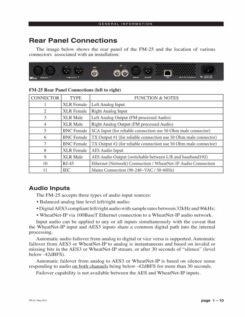
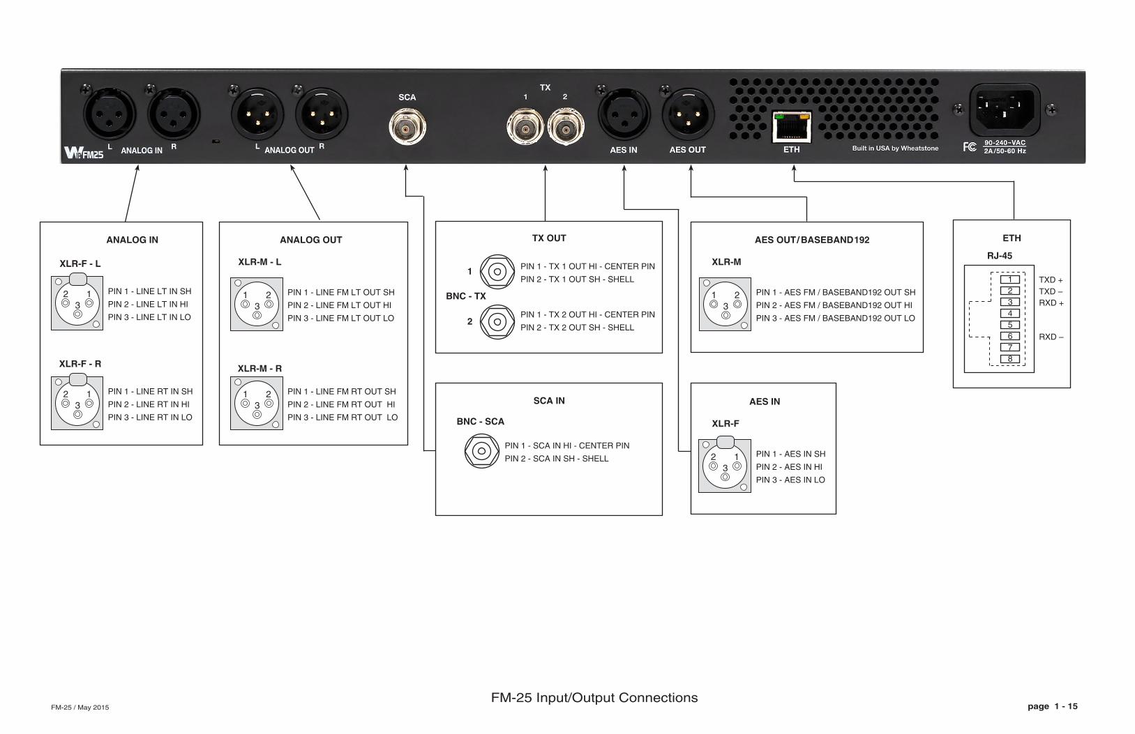
Rear Panel ConnectionsThe image below shows the rear panel of the FM‑25 and the location of various
connectors associated with an installation:
Audio InputsThe FM‑25 accepts three types of audio input sources:• Balanced analog line level left/right audio;• Digital AES3 compliant left/right audio with sample rates between 32kHz and 96kHz;• WheatNet‑IP via 100BaseT Ethernet connection to a WheatNet‑IP audio network.Input audio can be applied to any or all inputs simultaneously with the caveat that
the WheatNet‑IP input and AES3 inputs share a common digital path into the internal processing.
Automatic audio failover from analog to digital or vice versa is supported. Automatic failover from AES3 or WheatNet‑IP to analog is instantaneous and based on invalid or missing bits in the AES3 or WheatNet‑IP stream, or after 30 seconds of “silence” (level below ‑42dBFS).
Automatic failover from analog to AES3 or WheatNet‑IP is based on silence sense responding to audio on both channels being below ‑42dBFS for more than 30 seconds.
Failover capability is not available between the AES and WheatNet‑IP inputs.
CONNECTOR TYPE FUNCTION & NOTES1 XLR Female Left Analog Input2 XLR Female Right Analog Input3 XLR Male Left Analog Output (FM processed Audio)4 XLR Male Right Analog Output (FM processed Audio)5 BNC Female SCA Input (for reliable connection use 50 Ohm male connector)6 BNC Female TX Output #1 (for reliable connection use 50 Ohm male connector)7 BNC Female TX Output #2 (for reliable connection use 50 Ohm male connector)8 XLR Female AES Audio Input9 XLR Male AES Audio Output (switchable between L/R and baseband192)10 RJ‑45 Ethernet (Network) Connection / WheatNet-IP Audio Connection11 IEC Mains Connection (90-240~VAC / 50-60Hz)
FM-25 Rear Panel Connections (left to right)
page 1 – 11FM-25 / May 2015
G E N E R A L I N F O R M A T I O N
Analog In – XLR-FPin 1 XLR LT SH – LINE LT IN SHPin 2 XLR LT HI – LINE LT IN HIPin 3 XLR LT LO – LINE LT IN LO
Pin 1 XLR RT SH – LINE RT IN SHPin 2 XLR RT HI – LINE RT IN HIPin 3 XLR RT LO – LINE RT IN LO
AES In – XLR-FPin 1 XLR SH – AES IN SHPin 2 XLR HI – AES IN HIPin 3 XLR LO – AES IN LO
SCA In – BNCPin 1 BNC HI – SCA IN HI Pin 2 BNC SH – SCA IN SH
FM Audio OutputsOutput audio for the FM path is available as:• Balanced analog left/right stereo, pre‑emphasized.• Balanced analog left/right stereo, pre‑emphasized or de‑emphasized according to
pre‑emphasis in use.• AES3 digital left/right stereo, pre‑emphasized or de‑emphasized according to
pre‑emphasis in use.• AES3 digital composite (baseband192) connected to compatible transmitter*.• Unbalanced composite stereo on two BNC female connectors.• WheatNet‑IP audio network.
*The AES digital output connector is switchable between left/right stereo and digital composite (baseband192)
Analog Out – XLR-MPin 1 XLR LT SH – LINE FM LT OUT SHPin 2 XLR LT HI – LINE FM LT OUT HIPin 3 XLR LT LO – LINE FM LT OUT LO
Pin 1 XLR RT SH – LINE FM RT OUT SHPin 2 XLR RT HI – LINE FM RT OUT HIPin 3 XLR RT LO – LINE FM RT OUT LO
AES/ baseband192 Out – XLR-MPin 1 XLR SH – AES FM / BASEBAND192 OUT SHPin 2 XLR HI – AES FM / BASEBAND192 OUT HIPin 3 XLR LO – AES FM / BASEBAND192 OUT LO
page 1 – 12FM-25 / May 2015
G E N E R A L I N F O R M A T I O N
TX Out – BNCPin 1 BNC 1 HI – TX 1 OUT HI Pin 2 BNC 1 SH – TX 1 OUT SH
Pin 1 BNC 2 HI – TX 2 OUT HI Pin 2 BNC 2 SH – TX 2 OUT SH
Headphone MonitoringAn overload protected stereo headphone amplifier drives the front panel ¼" stereo
headphone output located on the left side of the FM‑25’s front panel. The audio source feeding the headphones may be chosen from the FM output or the analog and digital inputs, even if those inputs have not been selected to feed the audio processing chain. The System menu of the GUI hosts the headphone router selector as does the front panel interface.
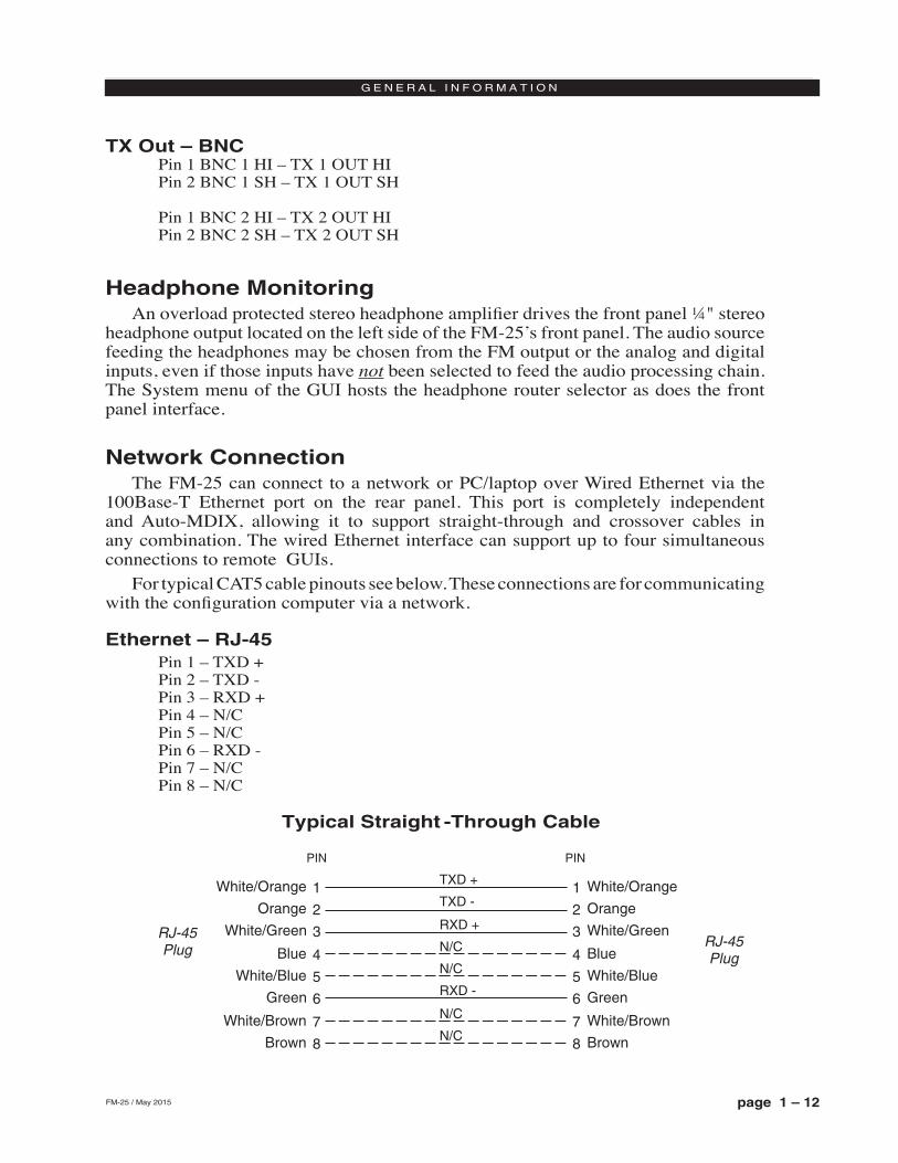
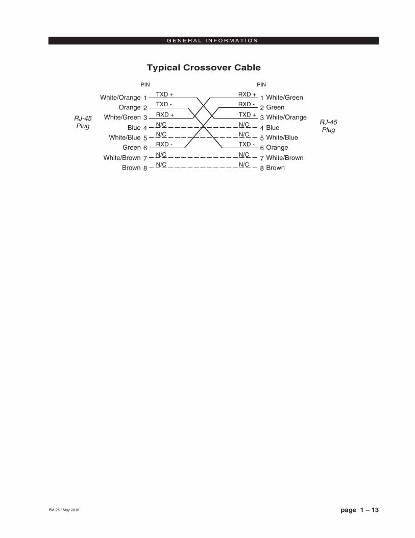
Network ConnectionThe FM‑25 can connect to a network or PC/laptop over Wired Ethernet via the
100Base‑T Ethernet port on the rear panel. This port is completely independent and Auto‑MDIX, allowing it to support straight‑through and crossover cables in any combination. The wired Ethernet interface can support up to four simultaneous connections to remote GUIs.
For typical CAT5 cable pinouts see below. These connections are for communicating with the configuration computer via a network.
Ethernet – RJ-45Pin 1 – TXD +Pin 2 – TXD ‑Pin 3 – RXD +Pin 4 – N/CPin 5 – N/CPin 6 – RXD ‑Pin 7 – N/CPin 8 – N/C
Typical Straight -Through Cable
1
2
3
4
TXD +
TXD -
RXD +
RXD -
PIN
1
2
3
4
PIN
RJ-45Plug RJ-45
Plug
White/Orange
5
6
7
8
N/C
N/C
5
6
7
8
Orange
White/Green
Blue
White/Blue
Green
White/Brown
Brown
N/C
N/C
White/Orange
Orange
White/Green
Blue
White/Blue
Green
White/Brown
Brown
page 1 – 13FM-25 / May 2015
G E N E R A L I N F O R M A T I O N
Typical Crossover Cable
1
2
3
4
TXD +
TXD -
RXD +
RXD -
PIN
1
2
3
4
PIN
RJ-45Plug RJ-45
Plug
White/Orange
5
6
7
8
N/C
N/C
5
6
7
8
Orange
White/Green
Blue
White/Blue
Green
White/Brown
Brown
White/Green
Green
White/Orange
Blue
White/Blue
Orange
White/Brown
Brown
N/C
N/C
RXD +
RXD -
TXD +
TXD -
N/C
N/C
N/C
N/C
page 1 – 14FM-25 / May 2015
G E N E R A L I N F O R M A T I O N
Processing PresetsThe FM‑25 comes equipped with several dozen factory presets and can hold a total
of 80 presets in its onboard memory. Customer‑created presets may be saved within the FM‑25’s onboard memory until all preset storage slots are full. An unlimited number of presets can be stored on the PC that hosts the Windows‑based remote control GUI software.
In order to prevent annoying clicks and pops when changing presets, preset parameters are slewed between the current values and the new values whenever a new preset is taken, and it may take several seconds for the new settings to completely settle in. It is important to remember this concept!
The FM-25’s preset behavior is purposely designed to make preset changes as unobtrusive as possible and therefore parameter changes are not instantaneous, but gracefully take place over a matter of seconds. This factor must be taken into consideration whenever switching back and forth between presets in order to compare them!
When a preset has been recalled and has not been modified the preset’s name is displayed in green text within the GUI’s current preset window. If changes to the preset have been made its name will be displayed in red text instead of green. Once the modified settings have been saved back to the FM‑25’s hardware the preset name will again be displayed in green.
Factory presets can be re‑tuned and saved as new preset names in order to create a completely different air sound. The factory presets are write‑protected and changes made to them cannot be written back to the same memory location. Factory presets that have been modified are considered by the system to be “user” presets and therefore must be saved as a new name and in a new preset storage slot.
Our advice is to start with a factory preset that has the on air sound that is closest to what you believe you need. If changes are necessary, the best approach is to make small changes, one or two at a time, and then listen for quite a while before deciding that more changes are necessary. A consultant friend of ours advises: “Tweak small and then listen large.”
NOTE: Preset storage is as follows:‑ Factory presets are installed beginning with a BYPASS stored in slot #9. Factory
presets cannot be written over or deleted.‑ User presets are stored above the highest‑numbered factory preset or in slots 1 ‑ 8.
The number of available slots for user presets depends on how many factory presets were installed, which can vary with software version. The total number of presets on the FM‑25’s hardware cannot exceed eighty (80). The storage space available for presets on the GUI’s host PC (because of a preset’s tiny file size) is virtually unlimited.
‑ User presets may be locked at the user’s discretion to prevent inadvertent changes. Any user can unlock user‑locked presets
1 23
XLR-M - L
PIN 1 - LINE FM LT OUT SH
PIN 2 - LINE FM LT OUT HI
PIN 3 - LINE FM LT OUT LO
1 23
XLR-M - R
PIN 1 - LINE FM RT OUT SH
PIN 2 - LINE FM RT OUT HI
PIN 3 - LINE FM RT OUT LO
2 13
ANALOG IN
XLR-F - L
PIN 1 - LINE LT IN SH
PIN 2 - LINE LT IN HI
PIN 3 - LINE LT IN LO
PIN 1 - LINE RT IN SH
PIN 2 - LINE RT IN HI
PIN 3 - LINE RT IN LO
XLR-F - R
2 13
page 1 - 15FM-25 Input/Output Connections
FM-25 / May 2015
ANALOG OUT
SCA IN
BNC - SCA
PIN 1 - SCA IN HI - CENTER PIN
PIN 2 - SCA IN SH - SHELL
BNC - TX
1
2
PIN 2 - TX 1 OUT SH - SHELL
PIN 1 - TX 1 OUT HI - CENTER PIN
PIN 2 - TX 2 OUT SH - SHELL
PIN 1 - TX 2 OUT HI - CENTER PIN
TX OUT
1 23
XLR-M
PIN 1 - AES FM / BASEBAND192 OUT SH
PIN 2 - AES FM / BASEBAND192 OUT HI
PIN 3 - AES FM / BASEBAND192 OUT LO
AES OUT/ BASEBAND192
XLR-F
PIN 1 - AES IN SH
PIN 2 - AES IN HI
PIN 3 - AES IN LO
AES IN
2 13
12345678
TXD +TXD –RXD +
RXD –
RJ-45
ETH
page 2 – 1FM-25 / May 2015
F R O N T P A N E L
FM-25 Front Panel
Meters .............................................................................................2-2
OLED Display .................................................................................2-2Headphone .................................................................................................................2-4
Source Selection .....................................................................................................2-4
Headphone Volume .................................................................................................2-4
Presets .......................................................................................................................2-4
Input ...........................................................................................................................2-4
Input Source ............................................................................................................2-4
Input Gain Adjustment .............................................................................................2-5
Pre-Emphasis .............................................................................................................2-5
Sound .........................................................................................................................2-5
Texture .....................................................................................................................2-5
EQ ............................................................................................................................2-6
Save .........................................................................................................................2-6
A Note About The Front Panel Sound Adjustments ................................................2-6
Output ........................................................................................................................2-7
Network ......................................................................................................................2-8
Changing The Network Settings ............................................................................2-8
Leading Zeroes ........................................................................................................2-8
Default IP Address ...................................................................................................2-8
Vesions .......................................................................................................................2-8
Access ........................................................................................................................2-9
Chapter Contents
page 2 – 2FM-25 / May 2015
F R O N T P A N E L
FM-25 Front Panel
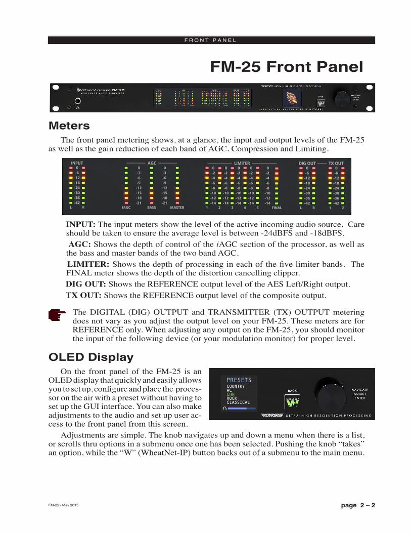
MetersThe front panel metering shows, at a glance, the input and output levels of the FM‑25
as well as the gain reduction of each band of AGC, Compression and Limiting.
INPUT: The input meters show the level of the active incoming audio source. Care should be taken to ensure the average level is between ‑24dBFS and ‑18dBFS.
AGC: Shows the depth of control of the iAGC section of the processor, as well as the bass and master bands of the two band AGC.
LIMITER: Shows the depth of processing in each of the five limiter bands. The FINAL meter shows the depth of the distortion cancelling clipper.
DIG OUT: Shows the REFERENCE output level of the AES Left/Right output. TX OUT: Shows the REFERENCE output level of the composite output.
The DIGITAL (DIG) OUTPUT and TRANSMITTER (TX) OUTPUT metering does not vary as you adjust the output level on your FM‑25. These meters are for REFERENCE only. When adjusting any output on the FM‑25, you should monitor the input of the following device (or your modulation monitor) for proper level.
OLED DisplayOn the front panel of the FM‑25 is an
OLED display that quickly and easily allows you to set up, configure and place the proces‑sor on the air with a preset without having to set up the GUI interface. You can also make adjustments to the audio and set up user ac‑cess to the front panel from this screen.
Adjustments are simple. The knob navigates up and down a menu when there is a list, or scrolls thru options in a submenu once one has been selected. Pushing the knob “takes” an option, while the “W” (WheatNet‑IP) button backs out of a submenu to the main menu.
page 2 – 3FM-25 / May 2015
F R O N T P A N E L
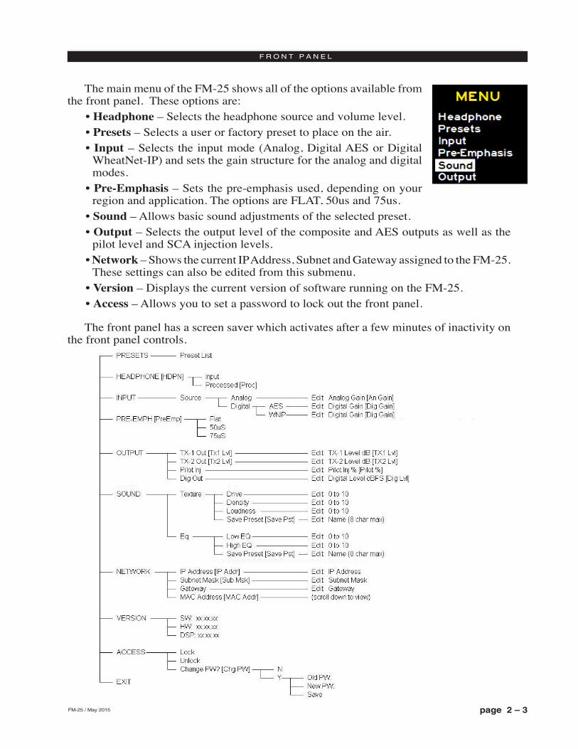
The main menu of the FM‑25 shows all of the options available from the front panel. These options are:
• Headphone – Selects the headphone source and volume level.• Presets – Selects a user or factory preset to place on the air.• Input – Selects the input mode (Analog, Digital AES or Digital
WheatNet‑IP) and sets the gain structure for the analog and digital modes.
• Pre-Emphasis – Sets the pre‑emphasis used, depending on your region and application. The options are FLAT, 50us and 75us.
• Sound – Allows basic sound adjustments of the selected preset. • Output – Selects the output level of the composite and AES outputs as well as the
pilot level and SCA injection levels.• Network – Shows the current IP Address, Subnet and Gateway assigned to the FM‑25.
These settings can also be edited from this submenu.• Version – Displays the current version of software running on the FM‑25.• Access – Allows you to set a password to lock out the front panel.
The front panel has a screen saver which activates after a few minutes of inactivity on the front panel controls.
page 2 – 4FM-25 / May 2015
F R O N T P A N E L
HeadphoneThe Headphone submenu gives you the option of adjusting the headphone volume as
well as selecting the monitoring source.
Source Selection
The first option is the monitoring source. To change the source, push in the knob and turn it to scroll through the options. Once you have arrived at the monitoring source you would like to hear, push the knob in. The monitoring options are:
• Input – The active input selected, either AES, WheatNet-IP or Analog)• Analog Input (“Ana Inp”)• Digital Input (“Dig Inp”) – Depending on the AES input selected on the input menu.
If AES is selected you will hear the AES input. If WheatNet‑IP is selected, you will hear that.
• FM Output (“FM Out”) – The FM out option allows you to monitor the processed signal just before it enters the MPX domain. The audio is peak controlled and pre‑emphasized. Matching de‑emphasis may be selected in the output menu.
Once the source has been selected by pressing in the knob, the front panel will exit the source selection mode.
Headphone Volume
To adjust the volume level, turn the knob to the second option and push the knob. You can then adjust the volume to a safe and comfortable level by turning the knob. Once complete, push the knob to exit the adjustment mode.
To return to the main menu, press the “W” BACK button.
PresetsThe Preset submenu allows the user to pick any of the factory or user presets that are
loaded onto the hardware. To select a preset, turn the knob to highlight and then push the knob in to activate the preset.
To return to the main menu, press the “W” BACK button.Management of presets on the hardware can be accomplished via the PC GUI program
that communicates with the FM‑25. You can add, delete and back up presets from the GUI. For more information about preset management with the GUI, please see page 3‑31 of this manual.
InputThe Input submenu allows you to change the input source to the processor as well as
adjust the input levels for each source independently.
Input Source
The first option is input source. To select the input source, highlight “input src” and push the knob in. Turn the knob to select the option you wish to place on air.

page 2 – 5FM-25 / May 2015
F R O N T P A N E L
The options are:• Digital AES (“Dig AES”). This is the audio that appears on the XLR AES3 input
jack on the back of the processor.• WheatNet-IP (“Dig WIP”). This is the audio that is streamed to the processor via the
Ethernet jack. This option should only be selected if the FM‑25 is part of a WheatNet‑IP AoIP system and the processor has been added to the system as a third‑party device. For more information on how to set up the FM‑25 for WheatNet‑IP, please see Appendix C of this manual.
• Analog (“Analog”). This is the audio that appears on the balanced XLR analog L/R input jacks on the back of the FM‑25.
Once the source has been selected by pressing in the knob, the front panel will exit the source selection mode.
Input Gain Adjustment
The second option in the submenu are adjustments of the analog and digital input levels. Highlight the gain adjustment for the active input (which was selected above) by turning the knob and then pressing in the knob. While watching the input meters on the front panel, adjust the input level so that the average level lights the ‑24dBFS LED with peaks no higher than ‑12dBFS.
If all the operating levels in your system are calibrated, your input gains should be a 0. If there is an issue where a level is too hot or cold, you can correct that here, however, it is advised to go back and look at where the level discrepancy originated and resolve the issue at that point, then return the operating level of the FM‑25 to unity gain.
Once the input gain has been adjusted, press the knob in to exit the adjustment option.To calibrate the levels of non‑active “backup audio source” inputs, you will need to
activate the input as the main input to see its operating levels. A more comprehensive input adjustment menu is available in the PC based GUI software, which includes a balance control and setting up main and backup audio sources.
To return to the main menu, press the “W” BACK button.
Pre-EmphasisPre‑Emphasis has three options: Off, 50uS, and 75uS. The Off position is useful for
testing and would not normally be used for broadcast. The 50uS or 75uS position should be selected to conform to your locale and regulatory requirements.
SoundProbably THE place you wanted to touch first… admit it! Sound can help adjust a
factory preset to tailor it to your tastes. The controls found here do basic adjustments only, to speed up or slow down the processing and to add or cut bass and highs.
Texture
The texture controls adjust the amount of processing, how fast the processing will react to gain changes and trade‑offs between clean audio and loud audio. Because of the advanced algorithms of the FM‑25, the tradeoff between loud and clean is much easier than in older analog designs or even inadequate or primitive digital processor designs
page 2 – 6FM-25 / May 2015
F R O N T P A N E L
from other manufacturers. Thus, you can get away with more “pushing the envelope” than ever before.
The three texture controls are:• Leveler Depth – Drives the AGC gain. Higher numbers mean the Leveler will work
harder to bring up low levels. Lower numbers mean the leveler will relax to a more open sound.
• Density – Determines how fast the processor will react to changes in level and how consistent the audio spectrum will remain cut to cut. Higher numbers mean faster changes and more consistent tonal balance. Lower numbers relax the audio and allow the spectrum to retain some of the intended source tonal balance.
• Loudness – Determines how fast the peak control processing will react. Higher numbers mean faster limiting and more clipping depth while lower numbers relax the limiters and clippers for a more open sound will still maintaining excellent peak control.
To access these controls, select the TEXTURE option by highlighting it and pressing in the knob. You can then highlight the texture feature you want to adjust by highlighting it and pressing in the knob. All the texture features are adjustable on a scale from 0‑10 with 0 being the lowest setting and 10 being the highest. The default for all factory presets is 5.
EQ
To access the EQ controls, select the EQ option by highlighting it and pressing in the knob. You can then highlight the EQ option you want to adjust by highlighting it and pressing in the knob. All EQ features are adjustable on a scale from 0‑10 with 0 being the lowest setting and 10 being the highest. The default for all factory presets is 5.
To return to the main menu, press the “W” BACK button.
Save
When you are finished adjusting the TEXTURE and EQ controls, you can save your work as a preset using the SAVE option. In the menu, highlight the SAVE option with the knob and press it in. The next empty user preset slot will appear with the option of naming your new preset (the FM-25 has 80 preset slots, the first 20 of which are used for factory presets). You can use the new slot, or turn the knob and select a different empty slot OR overwrite a previously saved user preset (factory presets CANNOT be overwritten).
Once a slot has been selected, you can name the preset using the knob. A flashing cursor will appear in the first character slot. Turn the knob to choose an alpha-numeric character and push select. The character will be written and the cursor will move on to the next character. When you are finished, push and HOLD the knob for approximately 3 seconds to save the preset. A total of 8 characters can be chosen for a preset saved on the front panel. These can only be alpha‑numeric (A‑Z or 0‑9). For longer, more descrip‑tive names, you can use the PC GUI to save the current preset with up to 64 characters.
A Note About The Front Panel Sound Adjustments
The front panel sound adjustments are set up so that users can quickly change the most basic settings in the audio processor to “get it” on the air and sounding good. Because we have tied together background controls to make the front panel adjustments easy, you
page 2 – 7FM-25 / May 2015
F R O N T P A N E L
can only modify factory presets from the front panel. User presets, adjusted and saved with the GUI software, cannot be modified from the front panel. Any preset may be selected, but only genuine Wheatstone factory presets can be modified using the sound controls on the front panel.
That being said, the front panel controls are very powerful for what they are. If you don’t want to bother with the GUI software, the best way to proceed with selecting and adjusting a preset using the front panel controls is to find a preset that closely matches the sound you are looking for. Don’t get too wrapped up with names… what may sound great for CHR in one market may be way too aggressive in another.
Each of the 5 controls has 10 options, which leads to 100,000 different settings that can be made JUST WITH the 5 front panel controls. In most markets, you can at least get up and running with something that sounds really good with just these 5 controls and the factory presets. In some markets, it may be ALL you need!
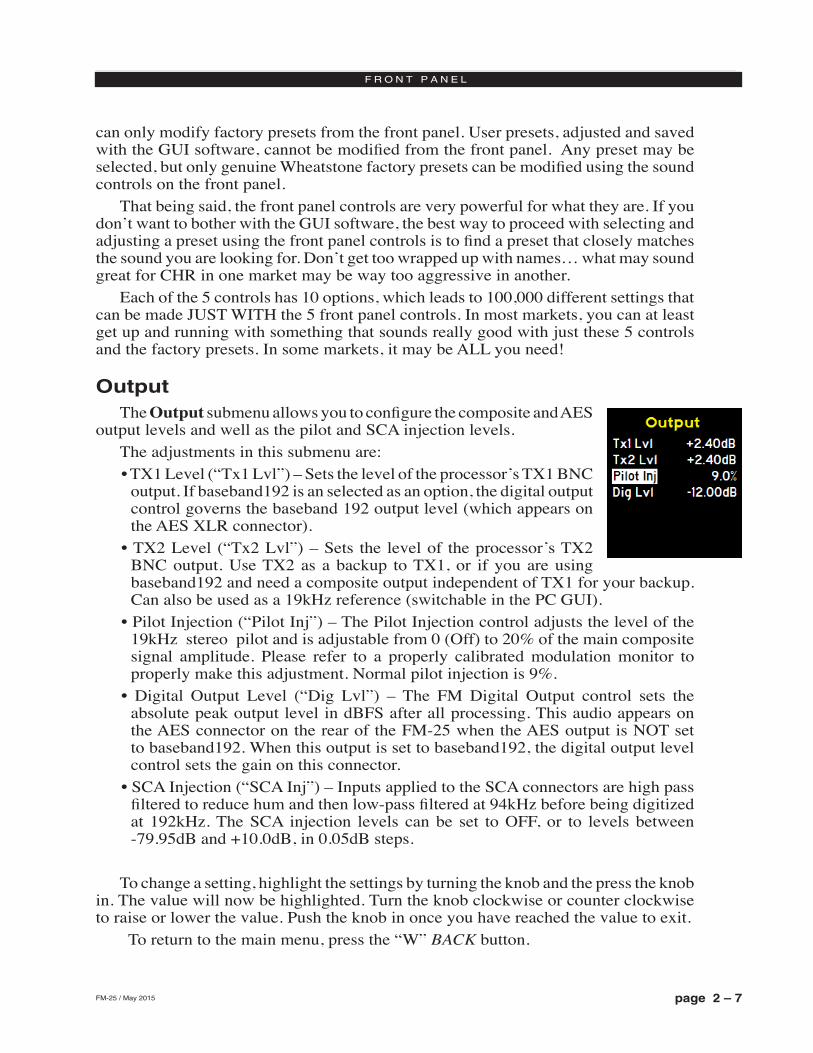
OutputThe Output submenu allows you to configure the composite and AES
output levels and well as the pilot and SCA injection levels. The adjustments in this submenu are:• TX1 Level (“Tx1 Lvl”) – Sets the level of the processor’s TX1 BNC
output. If baseband192 is an selected as an option, the digital output control governs the baseband 192 output level (which appears on the AES XLR connector).
• TX2 Level (“Tx2 Lvl”) – Sets the level of the processor’s TX2 BNC output. Use TX2 as a backup to TX1, or if you are using baseband192 and need a composite output independent of TX1 for your backup. Can also be used as a 19kHz reference (switchable in the PC GUI).
• Pilot Injection (“Pilot Inj”) – The Pilot Injection control adjusts the level of the 19kHz stereo pilot and is adjustable from 0 (Off) to 20% of the main composite signal amplitude. Please refer to a properly calibrated modulation monitor to properly make this adjustment. Normal pilot injection is 9%.
• Digital Output Level (“Dig Lvl”) – The FM Digital Output control sets the absolute peak output level in dBFS after all processing. This audio appears on the AES connector on the rear of the FM‑25 when the AES output is NOT set to baseband192. When this output is set to baseband192, the digital output level control sets the gain on this connector.
• SCA Injection (“SCA Inj”) – Inputs applied to the SCA connectors are high pass filtered to reduce hum and then low-pass filtered at 94kHz before being digitized at 192kHz. The SCA injection levels can be set to OFF, or to levels between ‑79.95dB and +10.0dB, in 0.05dB steps.
To change a setting, highlight the settings by turning the knob and the press the knob in. The value will now be highlighted. Turn the knob clockwise or counter clockwise to raise or lower the value. Push the knob in once you have reached the value to exit.
To return to the main menu, press the “W” BACK button.
page 2 – 8FM-25 / May 2015
F R O N T P A N E L
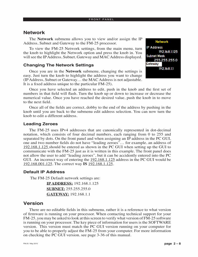
NetworkThe Network submenu allows you to view and/or assign the IP
Address, Subnet and Gateway to the FM‑25 processor.To view the FM‑25 Network settings, from the main menu, turn
the knob to highlight the Network option and press the knob in. You will see the IP Address, Subnet, Gateway and MAC Address displayed.
Changing The Network Settings
Once you are in the Network submenu, changing the settings is easy. Just turn the knob to highlight the address you want to change (IP Address, Subnet or Gateway… the MAC Address is not adjustable. It is a fixed address unique to the particular FM-25).
Once you have selected an address to edit, push in the knob and the first set of numbers in that field will flash. Turn the knob up or down to increase or decrease the numerical value. Once you have reached the desired value, push the knob in to move to the next field.
Once all of the fields are correct, dobby to the end of the address by pushing in the knob until you are back to the submenu edit address selection. You can now turn the knob to edit a different address.
Leading Zeroes
The FM‑25 uses IPv4 addresses that are canonically represented in dot‑decimal notation, which consists of four decimal numbers, each ranging from 0 to 255 and separated by dots. On the front panel and when assigning an IP address in the PC GUI, one and two number fields do not have “leading zeroes”… for example, an address of 192.168.1.125 should be entered as shown in the PC GUI when setting up the GUI to communicate with the FM‑25 just as it is written in this example. The front panel does not allow the user to add “leading zeroes”, but it can be accidently entered into the PC GUI. An incorrect way of entering the 192.168.1.125 address in the PC GUI would be 192.168.001.125. The correct way IS 192.168.1.125.
Default IP Address
The FM‑25 Default network settings are: IP ADDRESS: 192.168.1.125 SUBNET: 255.255.255.0 GATEWAY: 192.168.1.1
VersionThere are no editable fields in this submenu, rather it is a reference to what version
of firmware is running on your processor. When contacting technical support for your FM‑25, you may be asked to look at this screen to verify what version of FM‑25 software is running on your processor. The key piece of information for users is the SOFTWARE version. This version must match the PC GUI version running on your computer for you to be able to properly adjust the FM‑25 from your computer. For more information on checking the PC GUI version, see page 3‑36 of this manual.
page 2 – 9FM-25 / May 2015
F R O N T P A N E L
If the PC GUI and the version on the hardware are mismatched, you can contact Wheatstone Technical Support at +1‑252‑638‑7000 Monday thru Friday (except major US holidays) from 8:30am to 5:30pm Eastern time. You can also email your FM‑25 PC GUI and hardware versions to [email protected] to obtain a copy of the PC GUI that matches the version running on your hardware.
AccessAccess to the front panel of the FM‑25 can be restricted with a password. To set the front panel password:• From the main menu, turn the knob to the Access option and push in the knob.• Push the knob in again to Set Password (“Set PW”)• A dialogue will open with the cursor set on the first character. Turn the knob to
assign a numerical character as the first of four numbers. • When the character is set, push in the knob and the cursor will move to the next
slot.• Once the four digit password has been created, push and hold the knob to save
the password.
When anyone attempts to access the processor front panel, they will be met with a prompt to enter a password. To enter a password, turn the knob to the first character, scroll the correct digit, and press the knob in. The cursor will move to the next character. Continue in this manner until the password has been entered, then press and hold the knob. A message will tell you if the password is correct or incorrect.
It is important that you REMEMBER your password. Only numerical characters can be used in password creation. If you lose your password, please contact Wheatstone Technical Support at +1‑252‑638‑7000 Monday thru Friday (except major US holidays) from 8:30am to 5:30pm Eastern time.
page 3 – 1FM-25 / May 2015
F M - 2 5 G U I
Chapter Contents
FM-25 PC GUI
Getting Started ...............................................................................3-4
Connecting With the GUI ..............................................................3-5
Configuring the GUI ......................................................................3-5Connecting Directly Without a LAN ............................................................................3-5
The FM-25 and Internet Security Concerns ...............................................................3-6
About DHCP and the FM-25 .......................................................................................3-6
The FM-25 Network Protocols and Ports Used ..........................................................3-6
Using the FM-25 GUI .....................................................................3-7Dynamic Displays Region ...........................................................................................3-8
Frequency-Domain Graph .......................................................................................3-8
Managing the Blue Dots - Tutorial ...........................................................................3-8
Control Area Region ..................................................................................................3-10
Input Menu ..............................................................................................................3-11
Input Source .......................................................................................................3-11
Input Signal Presence ........................................................................................3-11
Analog Input Gain ...............................................................................................3-12
Digital Input Gain ................................................................................................3-12
L/R Balance ........................................................................................................3-12
Phase Rotator .....................................................................................................3-12
HPF - High Pass Filter ........................................................................................3-13
Metering ..............................................................................................................3-13
Multiband AGC Menu .............................................................................................3-14
A Word About Outboard Processors and Rreeveettbb .......................................3-16
Multibang AGC Controls .....................................................................................3-16
MB Compressor ..............................................................................................3-16
MB Leveler .....................................................................................................3-16
iAGC ...............................................................................................................3-16
RTZ Enable ....................................................................................................3-16
AGC Drive ......................................................................................................3-17
Gate Delay ......................................................................................................3-17
Gate Mode ......................................................................................................3-17
Gate Threshold ...............................................................................................3-17
Bass G/R Offset ..............................................................................................3-17
Stereo Enchance ............................................................................................3-17
page 3 – 2FM-25 / May 2015
F M - 2 5 G U I
Multiband AGC Dynamic Displays Menu ............................................................3-18
Threshold ........................................................................................................3-18
Attack ..............................................................................................................3-18
Release ..........................................................................................................3-19
FM Limiter Menu .....................................................................................................3-20
EQ, Limiter and Clippers Controls ......................................................................3-20
Pre-Emphasis .................................................................................................3-20
Limiter Drive ...................................................................................................3-20
Bass Enchance ...............................................................................................3-21
Enable ............................................................................................................3-21
Clipper Drive ...................................................................................................3-21
EQ LF/HF Shelf ..............................................................................................3-21
Limiters and Clippers Dynamic Displays Menu ..................................................3-22
Threshold ........................................................................................................3-22
Attack ..............................................................................................................3-22
Release ..........................................................................................................3-22
Stereo Generator Menu ..........................................................................................3-23
Mode ...................................................................................................................3-23
Composite Clipper Drive .....................................................................................3-23
Pilot Injection ......................................................................................................3-23
Multipath Limiter ................................................................................................3-23
SCA Level ...........................................................................................................3-24
Analog Output ....................................................................................................3-25
De-Emphasis ..................................................................................................3-25
PreDelay .........................................................................................................3-25
Digital Output .....................................................................................................3-25
Baseband192 and AES Modes ......................................................................3-25
De-Emphasis ..................................................................................................3-26
Sample Rate ...................................................................................................3-26
MPX Outputs ......................................................................................................3-26
System Menu ..........................................................................................................3-27
Input/Output Settings Change With Preset .........................................................3-27
Metering Data Over TCP/IP ................................................................................3-28
System Status ....................................................................................................3-28
Remote Login .....................................................................................................3-28
Front Panel .........................................................................................................3-29
GUI Access .........................................................................................................3-30
GUI Lock .............................................................................................................3-30
Side Bar Region ........................................................................................................3-31
Preset .....................................................................................................................3-31
Library .....................................................................................................................3-31
Locking Presets ..................................................................................................3-32
How to View Preset Changes .............................................................................3-32
page 3 – 3FM-25 / May 2015
F M - 2 5 G U I
Save .......................................................................................................................3-33
Devices ...................................................................................................................3-33
Headphone Control ................................................................................................3-33
Headphone Source .................................................................................................3-33
Title Bar Region .........................................................................................................3-34
Status .....................................................................................................................3-34
Device .....................................................................................................................3-34
Current Preset ........................................................................................................3-34
Notes on Online and Offline Working .....................................................................3-35
Accessing Menu Options ...........................................................................................3-36
File Menu Items ......................................................................................................3-36
Hardware Menu Items ............................................................................................3-36
FM-25 Hardware Update ....................................................................................3-36
Preset Menu Items .................................................................................................3-38
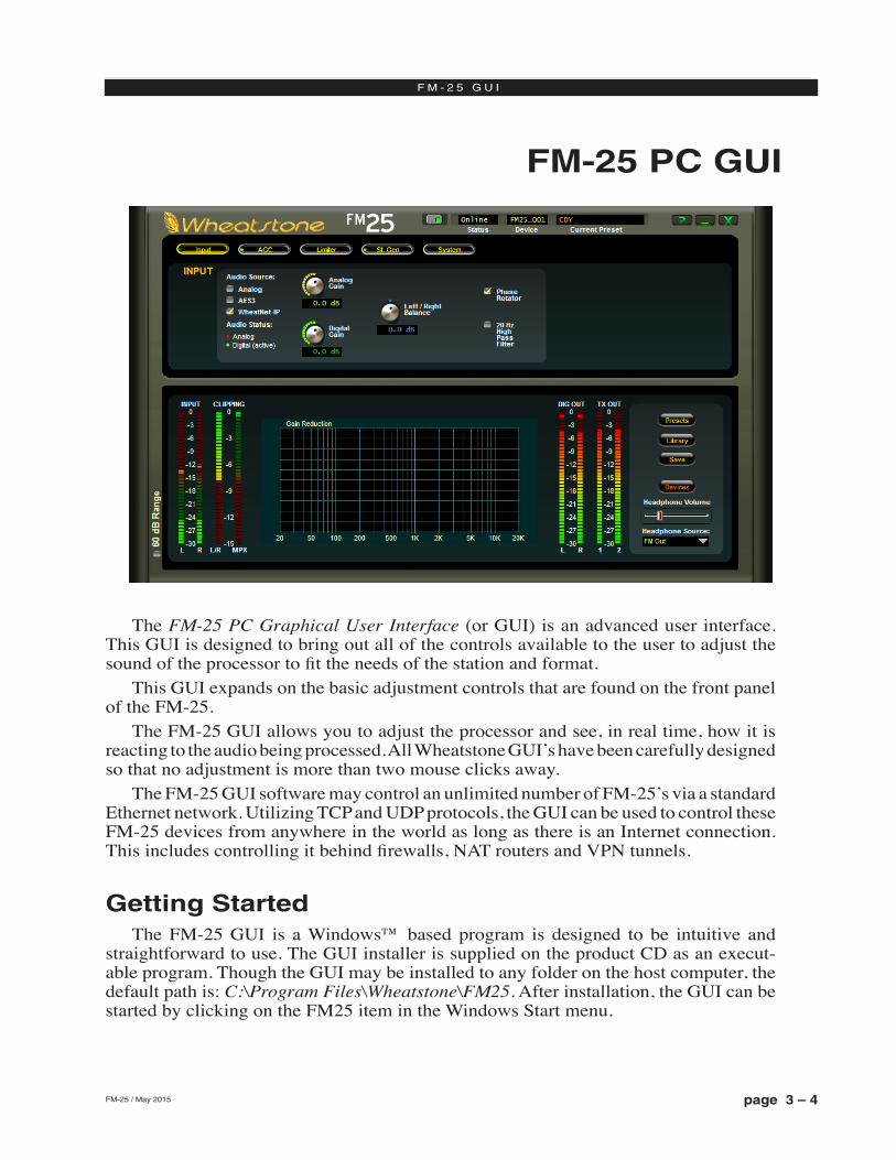
page 3 – 4FM-25 / May 2015
F M - 2 5 G U I
FM-25 PC GUI
The FM‑25 PC Graphical User Interface (or GUI) is an advanced user interface. This GUI is designed to bring out all of the controls available to the user to adjust the sound of the processor to fit the needs of the station and format.
This GUI expands on the basic adjustment controls that are found on the front panel of the FM‑25.
The FM‑25 GUI allows you to adjust the processor and see, in real time, how it is reacting to the audio being processed. All Wheatstone GUI’s have been carefully designed so that no adjustment is more than two mouse clicks away.
The FM‑25 GUI software may control an unlimited number of FM‑25’s via a standard Ethernet network. Utilizing TCP and UDP protocols, the GUI can be used to control these FM‑25 devices from anywhere in the world as long as there is an Internet connection. This includes controlling it behind firewalls, NAT routers and VPN tunnels.
Getting StartedThe FM‑25 GUI is a Windows™ based program is designed to be intuitive and
straightforward to use. The GUI installer is supplied on the product CD as an execut‑able program. Though the GUI may be installed to any folder on the host computer, the default path is: C:\Program Files\Wheatstone\FM25. After installation, the GUI can be started by clicking on the FM25 item in the Windows Start menu.
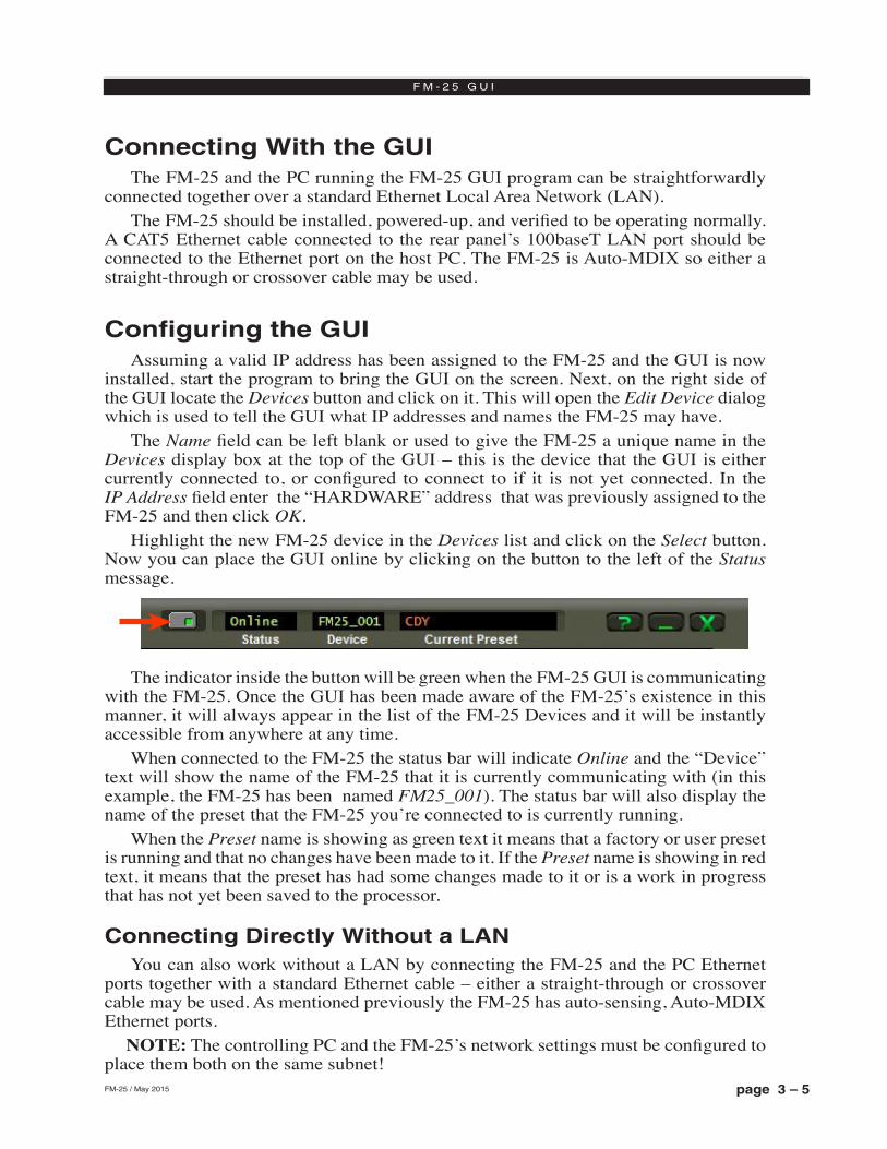
page 3 – 5FM-25 / May 2015
F M - 2 5 G U I
Connecting With the GUIThe FM‑25 and the PC running the FM‑25 GUI program can be straightforwardly
connected together over a standard Ethernet Local Area Network (LAN).The FM‑25 should be installed, powered‑up, and verified to be operating normally.
A CAT5 Ethernet cable connected to the rear panel’s 100baseT LAN port should be connected to the Ethernet port on the host PC. The FM‑25 is Auto‑MDIX so either a straight‑through or crossover cable may be used.
Configuring the GUIAssuming a valid IP address has been assigned to the FM‑25 and the GUI is now
installed, start the program to bring the GUI on the screen. Next, on the right side of the GUI locate the Devices button and click on it. This will open the Edit Device dialog which is used to tell the GUI what IP addresses and names the FM‑25 may have.
The Name field can be left blank or used to give the FM‑25 a unique name in the Devices display box at the top of the GUI – this is the device that the GUI is either currently connected to, or configured to connect to if it is not yet connected. In the IP Address field enter the “HARDWARE” address that was previously assigned to the FM‑25 and then click OK.
Highlight the new FM‑25 device in the Devices list and click on the Select button. Now you can place the GUI online by clicking on the button to the left of the Status message.
The indicator inside the button will be green when the FM‑25 GUI is communicating with the FM‑25. Once the GUI has been made aware of the FM‑25’s existence in this manner, it will always appear in the list of the FM‑25 Devices and it will be instantly accessible from anywhere at any time.
When connected to the FM‑25 the status bar will indicate Online and the “Device” text will show the name of the FM‑25 that it is currently communicating with (in this example, the FM‑25 has been named FM25_001). The status bar will also display the name of the preset that the FM‑25 you’re connected to is currently running.
When the Preset name is showing as green text it means that a factory or user preset is running and that no changes have been made to it. If the Preset name is showing in red text, it means that the preset has had some changes made to it or is a work in progress that has not yet been saved to the processor.
Connecting Directly Without a LANYou can also work without a LAN by connecting the FM‑25 and the PC Ethernet
ports together with a standard Ethernet cable – either a straight‑through or crossover cable may be used. As mentioned previously the FM‑25 has auto‑sensing, Auto‑MDIX Ethernet ports. NOTE: The controlling PC and the FM‑25’s network settings must be configured to place them both on the same subnet!
page 3 – 6FM-25 / May 2015
F M - 2 5 G U I
The FM-25 and Internet Security ConcernsThe FM‑25 does not act as a “web device” or “web server,” nor does it support open
ports to the Internet. Therefore there is no worry that someone could “hack” into the FM‑25 and use it as a pathway to the rest of the network to which it is connected.
About DHCP and the FM-25 The FM‑25 does not utilize DHCP – Dynamic Host Configuration Protocol (or
automatically assigned network addressing) – and needs to be assigned a “STATIC” network‑unique IP address. Most DHCP servers assign addresses starting at the bottom of the group 192.168.0.xxx. Therefore choosing an address high in that group, say 192.168.0.200, as a static IP address will likely keep it out of the way of the busiest DHCP addressing.
However, it’s always wise to check with your network administrator to determine what static IP addresses may be open and usable for the FM‑25. Sometimes the local network warrants the “Subnet” and “Gateway” values to be vastly different, but our suggested starting values for the Subnet and for the Gateway usually suffice for all but the most complex situations.
The FM-25 Network Protocols and Ports UsedThe FM‑25 uses both TCP and UDP protocols to communicate with the remote GUI.
TCP is used from the GUI to the FM‑25 because its high reliability ensures that all control changes sent to the FM‑25 will be received with 100% accuracy. The UDP protocol is used by FM‑25 to send and update metering and other real time data back to the GUI. The TCP protocol uses port 55903. The UDP Protocol uses a port in the range between 60000 and 60010. It tries 60000 first and if it is busy it tries 60001 next. This process repeats if necessary until an idle UDP port is found. Note that FM‑25 requires these ports to be open through any firewalls for successful connectivity.
For information on configuring the Network settings on the FM‑25, please see page 2‑8 of this manual.
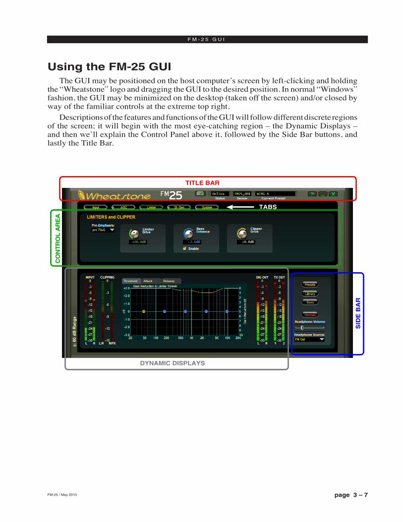
page 3 – 7FM-25 / May 2015
F M - 2 5 G U I
Using the FM-25 GUIThe GUI may be positioned on the host computer’s screen by left‑clicking and holding
the “Wheatstone” logo and dragging the GUI to the desired position. In normal “Windows” fashion, the GUI may be minimized on the desktop (taken off the screen) and/or closed by way of the familiar controls at the extreme top right.
Descriptions of the features and functions of the GUI will follow different discrete regions of the screen; it will begin with the most eye‑catching region – the Dynamic Displays – and then we’ll explain the Control Panel above it, followed by the Side Bar buttons, and lastly the Title Bar.
SID
E B
AR
TITLE BAR
CO
NT
RO
L A
RE
A
DYNAMIC DISPLAYS
TABS
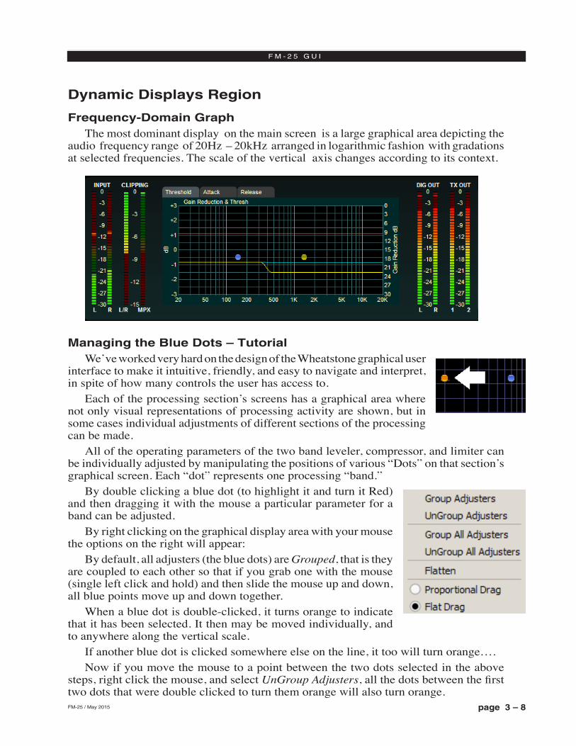
page 3 – 8FM-25 / May 2015
F M - 2 5 G U I
Dynamic Displays Region
Frequency-Domain GraphThe most dominant display on the main screen is a large graphical area depicting the
audio frequency range of 20Hz – 20kHz arranged in logarithmic fashion with gradations at selected frequencies. The scale of the vertical axis changes according to its context.
Managing the Blue Dots – TutorialWe’ve worked very hard on the design of the Wheatstone graphical user
interface to make it intuitive, friendly, and easy to navigate and interpret, in spite of how many controls the user has access to.
Each of the processing section’s screens has a graphical area where not only visual representations of processing activity are shown, but in some cases individual adjustments of different sections of the processing can be made.
All of the operating parameters of the two band leveler, compressor, and limiter can be individually adjusted by manipulating the positions of various “Dots” on that section’s graphical screen. Each “dot” represents one processing “band.”
By double clicking a blue dot (to highlight it and turn it Red) and then dragging it with the mouse a particular parameter for a band can be adjusted.
By right clicking on the graphical display area with your mouse the options on the right will appear:
By default, all adjusters (the blue dots) are Grouped, that is they are coupled to each other so that if you grab one with the mouse (single left click and hold) and then slide the mouse up and down, all blue points move up and down together.
When a blue dot is double‑clicked, it turns orange to indicate that it has been selected. It then may be moved individually, and to anywhere along the vertical scale.
If another blue dot is clicked somewhere else on the line, it too will turn orange….Now if you move the mouse to a point between the two dots selected in the above
steps, right click the mouse, and select UnGroup Adjusters, all the dots between the first two dots that were double clicked to turn them orange will also turn orange.
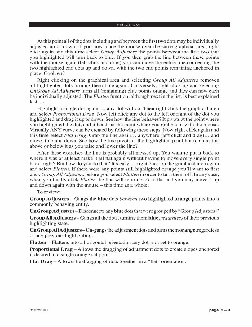
page 3 – 9FM-25 / May 2015
F M - 2 5 G U I
At this point all of the dots including and between the first two dots may be individually adjusted up or down. If you now place the mouse over the same graphical area, right click again and this time select Group Adjusters the points between the first two that you highlighted will turn back to blue. If you then grab the line between these points with the mouse again (left click and drag) you can move the entire line connecting the two highlighted end dots up and down, with the two end points remaining anchored in place. Cool, eh?
Right clicking on the graphical area and selecting Group All Adjusters removes all highlighted dots turning them blue again. Conversely, right clicking and selecting UnGroup All Adjusters turns all (remaining) blue points orange and they can now each be individually adjusted. The Flatten function, although next in the list, is best explained last….
Highlight a single dot again … any dot will do. Then right click the graphical area and select Proportional Drag. Now left click any dot to the left or right of the dot you highlighted and drag it up or down. See how the line behaves? It pivots at the point where you highlighted the dot, and it bends at the point where you grabbed it with the mouse. Virtually ANY curve can be created by following these steps. Now right click again and this time select Flat Drag. Grab the line again… anywhere (left click and drag)… and move it up and down. See how the line pivots at the highlighted point but remains flat above or below it as you raise and lower the line?
After these exercises the line is probably all messed up. You want to put it back to where it was or at least make it all flat again without having to move every single point back, right? But how do you do that? It’s easy ... right click on the graphical area again and select Flatten. If there were any points still highlighted orange you’ll want to first click Group All Adjusters before you select Flatten in order to turn them off. In any case, when you finally click Flatten the line will return back to flat and you may move it up and down again with the mouse – this time as a whole.
To review:Group Adjusters – Gangs the blue dots between two highlighted orange points into a commonly behaving entity.UnGroup Adjusters – Disconnects any blue dots that were grouped by “Group Adjusters.”Group All Adjusters – Gangs all the dots, turning them blue, regardless of their previous highlighting state.UnGroup All Adjusters – Un‑gangs the adjustment dots and turns them orange, regardless of any previous highlighting.Flatten – Flattens into a horizontal orientation any dots not set to orange.Proportional Drag – Allows the dragging of adjustment dots to create slopes anchored if desired to a single orange set point.Flat Drag – Allows the dragging of dots together in a “flat” orientation.
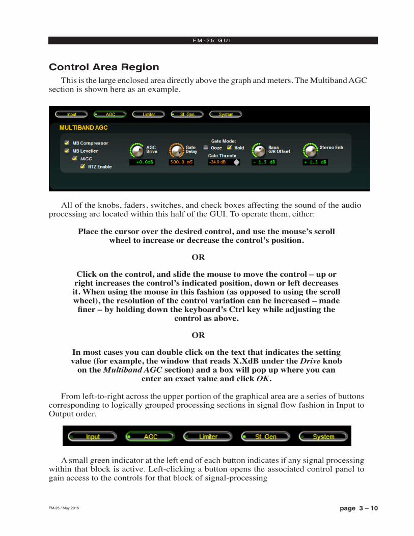
page 3 – 10FM-25 / May 2015
F M - 2 5 G U I
Control Area RegionThis is the large enclosed area directly above the graph and meters. The Multiband AGC
section is shown here as an example.
All of the knobs, faders, switches, and check boxes affecting the sound of the audio processing are located within this half of the GUI. To operate them, either:
Place the cursor over the desired control, and use the mouse’s scroll wheel to increase or decrease the control’s position.
OR
Click on the control, and slide the mouse to move the control – up or right increases the control’s indicated position, down or left decreases it. When using the mouse in this fashion (as opposed to using the scroll wheel), the resolution of the control variation can be increased – made
finer – by holding down the keyboard’s Ctrl key while adjusting the control as above.
OR
In most cases you can double click on the text that indicates the setting value (for example, the window that reads X.XdB under the Drive knob
on the Multiband AGC section) and a box will pop up where you can enter an exact value and click OK.
From left‑to‑right across the upper portion of the graphical area are a series of buttons corresponding to logically grouped processing sections in signal flow fashion in Input to Output order.
A small green indicator at the left end of each button indicates if any signal processing within that block is active. Left‑clicking a button opens the associated control panel to gain access to the controls for that block of signal‑processing
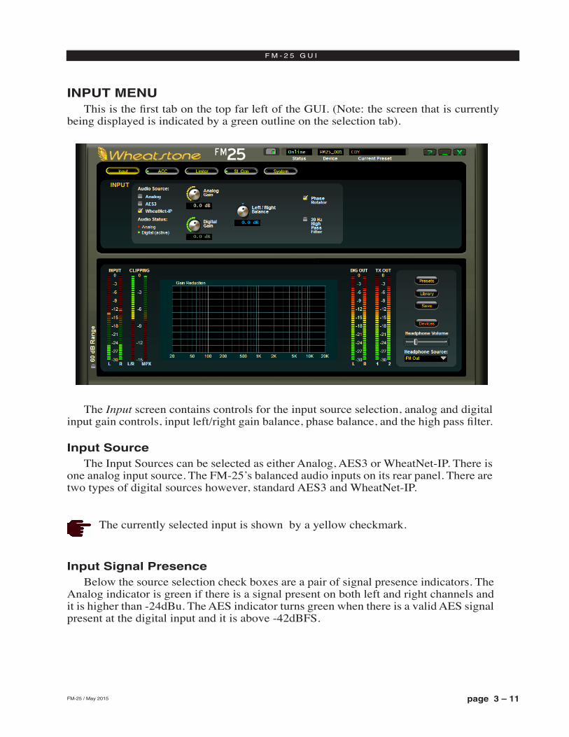
page 3 – 11FM-25 / May 2015
F M - 2 5 G U I
INPUT MENUThis is the first tab on the top far left of the GUI. (Note: the screen that is currently
being displayed is indicated by a green outline on the selection tab).
The currently selected input is shown by a yellow checkmark.
Input Signal PresenceBelow the source selection check boxes are a pair of signal presence indicators. The
Analog indicator is green if there is a signal present on both left and right channels and it is higher than ‑24dBu. The AES indicator turns green when there is a valid AES signal present at the digital input and it is above ‑42dBFS.
The Input screen contains controls for the input source selection, analog and digital input gain controls, input left/right gain balance, phase balance, and the high pass filter.
Input SourceThe Input Sources can be selected as either Analog, AES3 or WheatNet‑IP. There is
one analog input source. The FM‑25’s balanced audio inputs on its rear panel. There are two types of digital sources however, standard AES3 and WheatNet‑IP.
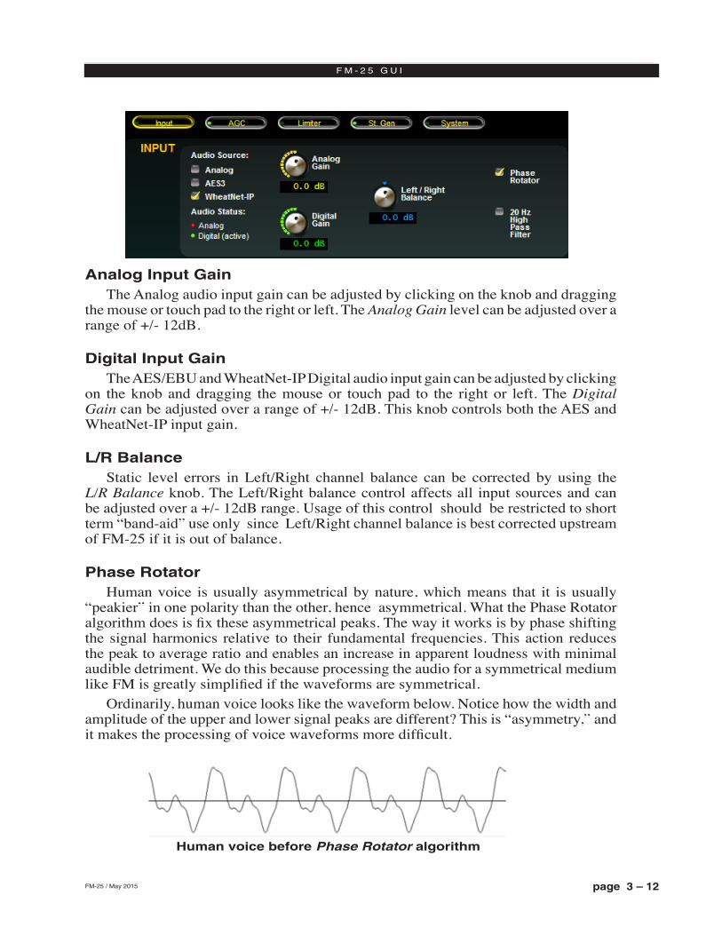
page 3 – 12FM-25 / May 2015
F M - 2 5 G U I
Analog Input GainThe Analog audio input gain can be adjusted by clicking on the knob and dragging
the mouse or touch pad to the right or left. The Analog Gain level can be adjusted over a range of +/‑ 12dB.
Digital Input GainThe AES/EBU and WheatNet‑IP Digital audio input gain can be adjusted by clicking
on the knob and dragging the mouse or touch pad to the right or left. The Digital Gain can be adjusted over a range of +/‑ 12dB. This knob controls both the AES and WheatNet‑IP input gain.
L/R BalanceStatic level errors in Left/Right channel balance can be corrected by using the
L/R Balance knob. The Left/Right balance control affects all input sources and can be adjusted over a +/‑ 12dB range. Usage of this control should be restricted to short term “band‑aid” use only since Left/Right channel balance is best corrected upstream of FM‑25 if it is out of balance.
Phase RotatorHuman voice is usually asymmetrical by nature, which means that it is usually
“peakier” in one polarity than the other, hence asymmetrical. What the Phase Rotator algorithm does is fix these asymmetrical peaks. The way it works is by phase shifting the signal harmonics relative to their fundamental frequencies. This action reduces the peak to average ratio and enables an increase in apparent loudness with minimal audible detriment. We do this because processing the audio for a symmetrical medium like FM is greatly simplified if the waveforms are symmetrical.
Ordinarily, human voice looks like the waveform below. Notice how the width and amplitude of the upper and lower signal peaks are different? This is “asymmetry,” and it makes the processing of voice waveforms more difficult.
Human voice before Phase Rotator algorithm
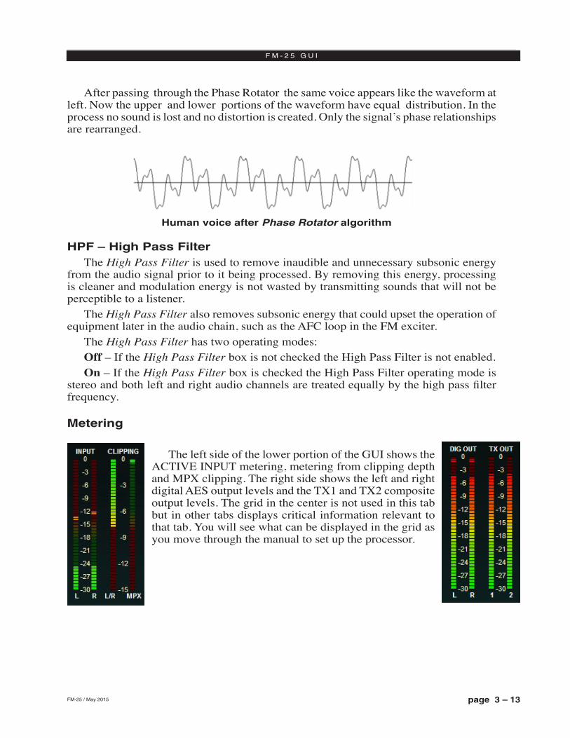
page 3 – 13FM-25 / May 2015
F M - 2 5 G U I
After passing through the Phase Rotator the same voice appears like the waveform at left. Now the upper and lower portions of the waveform have equal distribution. In the process no sound is lost and no distortion is created. Only the signal’s phase relationships are rearranged.
HPF – High Pass FilterThe High Pass Filter is used to remove inaudible and unnecessary subsonic energy
from the audio signal prior to it being processed. By removing this energy, processing is cleaner and modulation energy is not wasted by transmitting sounds that will not be perceptible to a listener.
The High Pass Filter also removes subsonic energy that could upset the operation of equipment later in the audio chain, such as the AFC loop in the FM exciter.
The High Pass Filter has two operating modes:Off – If the High Pass Filter box is not checked the High Pass Filter is not enabled.On – If the High Pass Filter box is checked the High Pass Filter operating mode is
stereo and both left and right audio channels are treated equally by the high pass filter frequency.
Metering
The left side of the lower portion of the GUI shows the ACTIVE INPUT metering, metering from clipping depth and MPX clipping. The right side shows the left and right digital AES output levels and the TX1 and TX2 composite output levels. The grid in the center is not used in this tab but in other tabs displays critical information relevant to that tab. You will see what can be displayed in the grid as you move through the manual to set up the processor.
Human voice after Phase Rotator algorithm
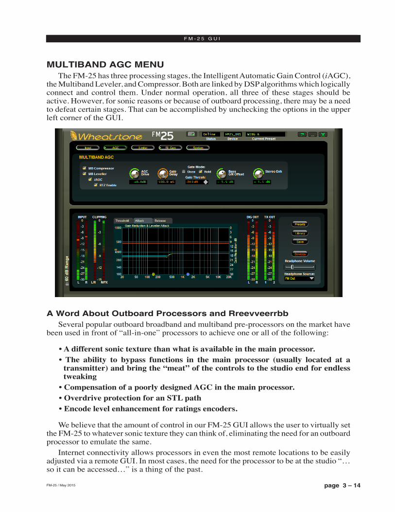
page 3 – 14FM-25 / May 2015
F M - 2 5 G U I
MULTIBAND AGC MENUThe FM‑25 has three processing stages, the Intelligent Automatic Gain Control (iAGC),
the Multiband Leveler, and Compressor. Both are linked by DSP algorithms which logically connect and control them. Under normal operation, all three of these stages should be active. However, for sonic reasons or because of outboard processing, there may be a need to defeat certain stages. That can be accomplished by unchecking the options in the upper left corner of the GUI.
A Word About Outboard Processors and RreevveerrbbSeveral popular outboard broadband and multiband pre‑processors on the market have
been used in front of “all‑in‑one” processors to achieve one or all of the following:
• A different sonic texture than what is available in the main processor.• The ability to bypass functions in the main processor (usually located at a
transmitter) and bring the “meat” of the controls to the studio end for endless tweaking
• Compensation of a poorly designed AGC in the main processor.• Overdrive protection for an STL path• Encode level enhancement for ratings encoders.
We believe that the amount of control in our FM‑25 GUI allows the user to virtually set the FM‑25 to whatever sonic texture they can think of, eliminating the need for an outboard processor to emulate the same.
Internet connectivity allows processors in even the most remote locations to be easily adjusted via a remote GUI. In most cases, the need for the processor to be at the studio “…so it can be accessed…” is a thing of the past.
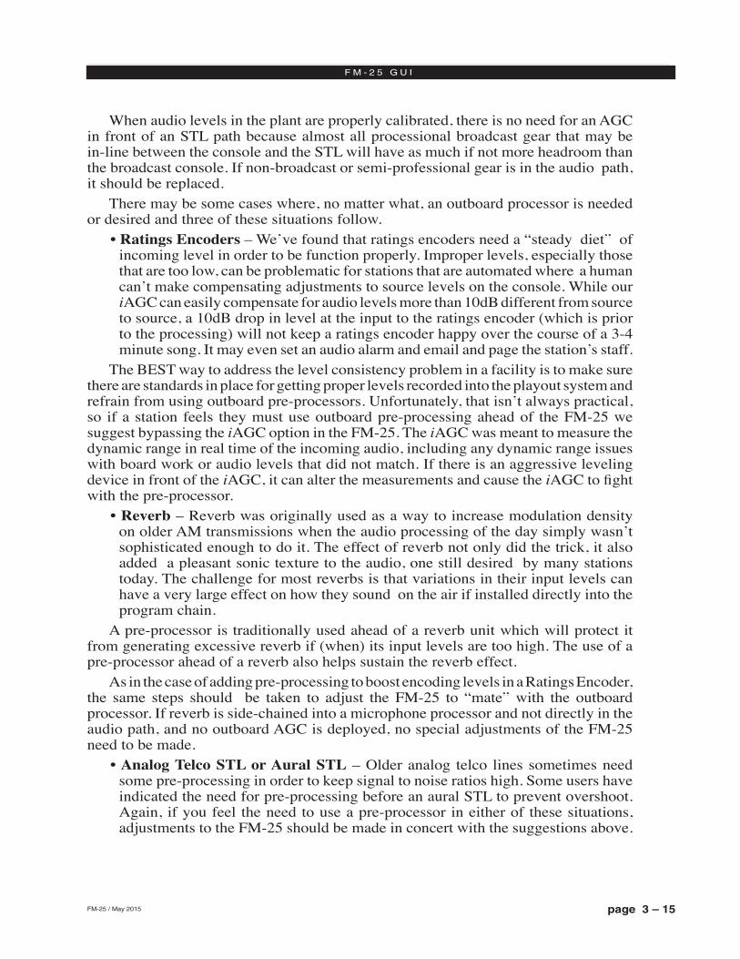
page 3 – 15FM-25 / May 2015
F M - 2 5 G U I
When audio levels in the plant are properly calibrated, there is no need for an AGC in front of an STL path because almost all processional broadcast gear that may be in‑line between the console and the STL will have as much if not more headroom than the broadcast console. If non‑broadcast or semi‑professional gear is in the audio path, it should be replaced.
There may be some cases where, no matter what, an outboard processor is needed or desired and three of these situations follow.
• Ratings Encoders – We’ve found that ratings encoders need a “steady diet” of incoming level in order to be function properly. Improper levels, especially those that are too low, can be problematic for stations that are automated where a human can’t make compensating adjustments to source levels on the console. While our iAGC can easily compensate for audio levels more than 10dB different from source to source, a 10dB drop in level at the input to the ratings encoder (which is prior to the processing) will not keep a ratings encoder happy over the course of a 3‑4 minute song. It may even set an audio alarm and email and page the station’s staff.
The BEST way to address the level consistency problem in a facility is to make sure there are standards in place for getting proper levels recorded into the playout system and refrain from using outboard pre‑processors. Unfortunately, that isn’t always practical, so if a station feels they must use outboard pre‑processing ahead of the FM‑25 we suggest bypassing the iAGC option in the FM‑25. The iAGC was meant to measure the dynamic range in real time of the incoming audio, including any dynamic range issues with board work or audio levels that did not match. If there is an aggressive leveling device in front of the iAGC, it can alter the measurements and cause the iAGC to fight with the pre‑processor.
• Reverb – Reverb was originally used as a way to increase modulation density on older AM transmissions when the audio processing of the day simply wasn’t sophisticated enough to do it. The effect of reverb not only did the trick, it also added a pleasant sonic texture to the audio, one still desired by many stations today. The challenge for most reverbs is that variations in their input levels can have a very large effect on how they sound on the air if installed directly into the program chain.
A pre‑processor is traditionally used ahead of a reverb unit which will protect it from generating excessive reverb if (when) its input levels are too high. The use of a pre‑processor ahead of a reverb also helps sustain the reverb effect.
As in the case of adding pre‑processing to boost encoding levels in a Ratings Encoder, the same steps should be taken to adjust the FM‑25 to “mate” with the outboard processor. If reverb is side‑chained into a microphone processor and not directly in the audio path, and no outboard AGC is deployed, no special adjustments of the FM‑25 need to be made.
• Analog Telco STL or Aural STL – Older analog telco lines sometimes need some pre‑processing in order to keep signal to noise ratios high. Some users have indicated the need for pre‑processing before an aural STL to prevent overshoot. Again, if you feel the need to use a pre‑processor in either of these situations, adjustments to the FM‑25 should be made in concert with the suggestions above.
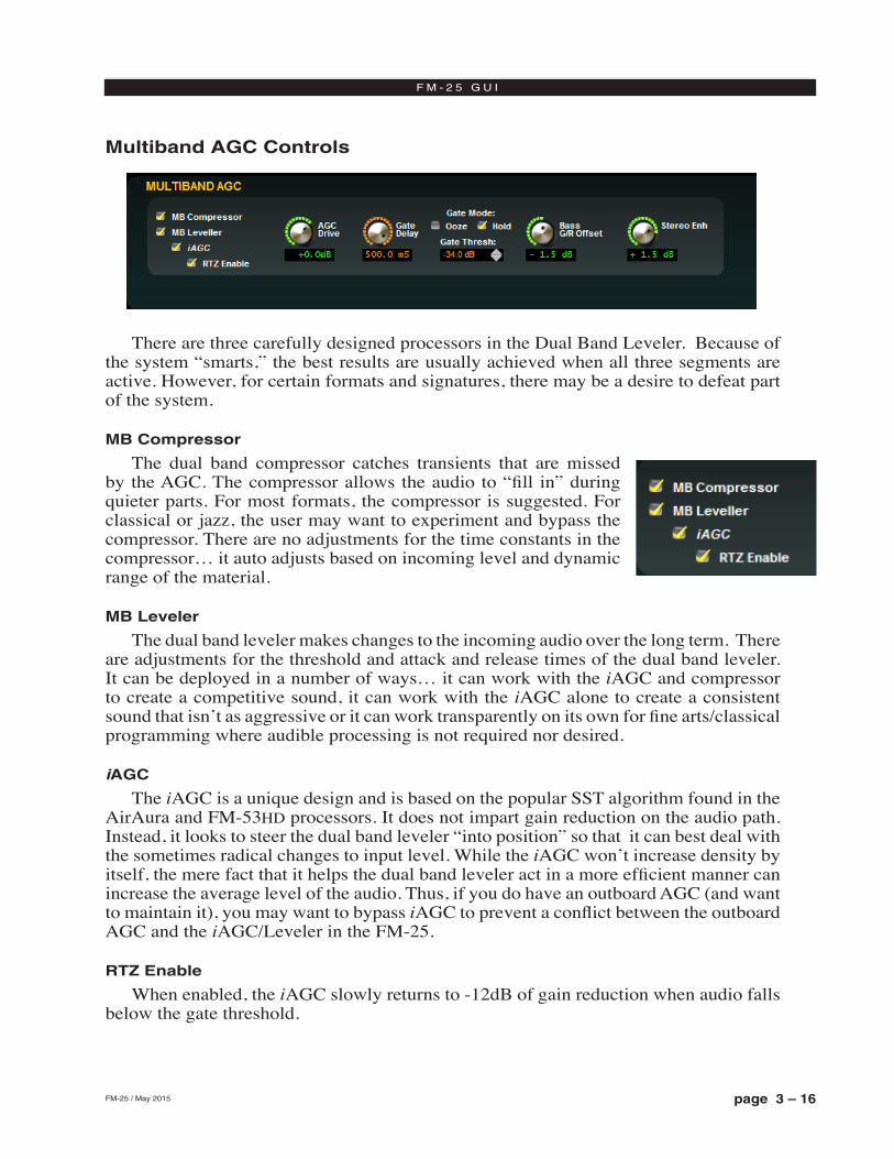
page 3 – 16FM-25 / May 2015
F M - 2 5 G U I
Multiband AGC Controls
There are three carefully designed processors in the Dual Band Leveler. Because of the system “smarts,” the best results are usually achieved when all three segments are active. However, for certain formats and signatures, there may be a desire to defeat part of the system.
MB Compressor
The dual band compressor catches transients that are missed by the AGC. The compressor allows the audio to “fill in” during quieter parts. For most formats, the compressor is suggested. For classical or jazz, the user may want to experiment and bypass the compressor. There are no adjustments for the time constants in the compressor… it auto adjusts based on incoming level and dynamic range of the material.
MB Leveler
The dual band leveler makes changes to the incoming audio over the long term. There are adjustments for the threshold and attack and release times of the dual band leveler. It can be deployed in a number of ways… it can work with the iAGC and compressor to create a competitive sound, it can work with the iAGC alone to create a consistent sound that isn’t as aggressive or it can work transparently on its own for fine arts/classical programming where audible processing is not required nor desired.
iAGC
The iAGC is a unique design and is based on the popular SST algorithm found in the AirAura and FM‑53hd processors. It does not impart gain reduction on the audio path. Instead, it looks to steer the dual band leveler “into position” so that it can best deal with the sometimes radical changes to input level. While the iAGC won’t increase density by itself, the mere fact that it helps the dual band leveler act in a more efficient manner can increase the average level of the audio. Thus, if you do have an outboard AGC (and want to maintain it), you may want to bypass iAGC to prevent a conflict between the outboard AGC and the iAGC/Leveler in the FM‑25.
RTZ Enable
When enabled, the iAGC slowly returns to ‑12dB of gain reduction when audio falls below the gate threshold.
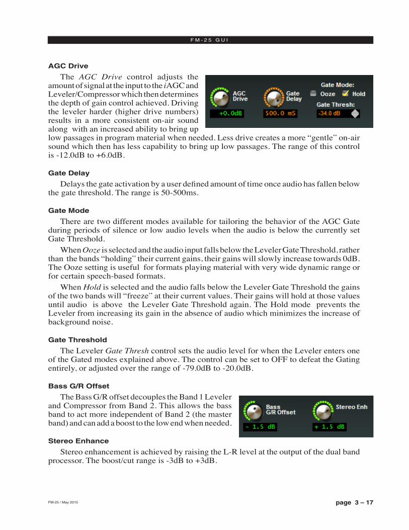
page 3 – 17FM-25 / May 2015
F M - 2 5 G U I
AGC Drive
The AGC Drive control adjusts the amount of signal at the input to the iAGC and Leveler/Compressor which then determines the depth of gain control achieved. Driving the leveler harder (higher drive numbers) results in a more consistent on‑air sound along with an increased ability to bring up low passages in program material when needed. Less drive creates a more “gentle” on‑air sound which then has less capability to bring up low passages. The range of this control is ‑12.0dB to +6.0dB.
Gate Delay
Delays the gate activation by a user defined amount of time once audio has fallen below the gate threshold. The range is 50‑500ms.
Gate Mode
There are two different modes available for tailoring the behavior of the AGC Gate during periods of silence or low audio levels when the audio is below the currently set Gate Threshold.
When Ooze is selected and the audio input falls below the Leveler Gate Threshold, rather than the bands “holding” their current gains, their gains will slowly increase towards 0dB. The Ooze setting is useful for formats playing material with very wide dynamic range or for certain speech‑based formats.
When Hold is selected and the audio falls below the Leveler Gate Threshold the gains of the two bands will “freeze” at their current values. Their gains will hold at those values until audio is above the Leveler Gate Threshold again. The Hold mode prevents the Leveler from increasing its gain in the absence of audio which minimizes the increase of background noise.
Gate Threshold
The Leveler Gate Thresh control sets the audio level for when the Leveler enters one of the Gated modes explained above. The control can be set to OFF to defeat the Gating entirely, or adjusted over the range of ‑79.0dB to ‑20.0dB.
Bass G/R Offset
The Bass G/R offset decouples the Band 1 Leveler and Compressor from Band 2. This allows the bass band to act more independent of Band 2 (the master band) and can add a boost to the low end when needed.
Stereo Enhance
Stereo enhancement is achieved by raising the L‑R level at the output of the dual band processor. The boost/cut range is ‑3dB to +3dB.
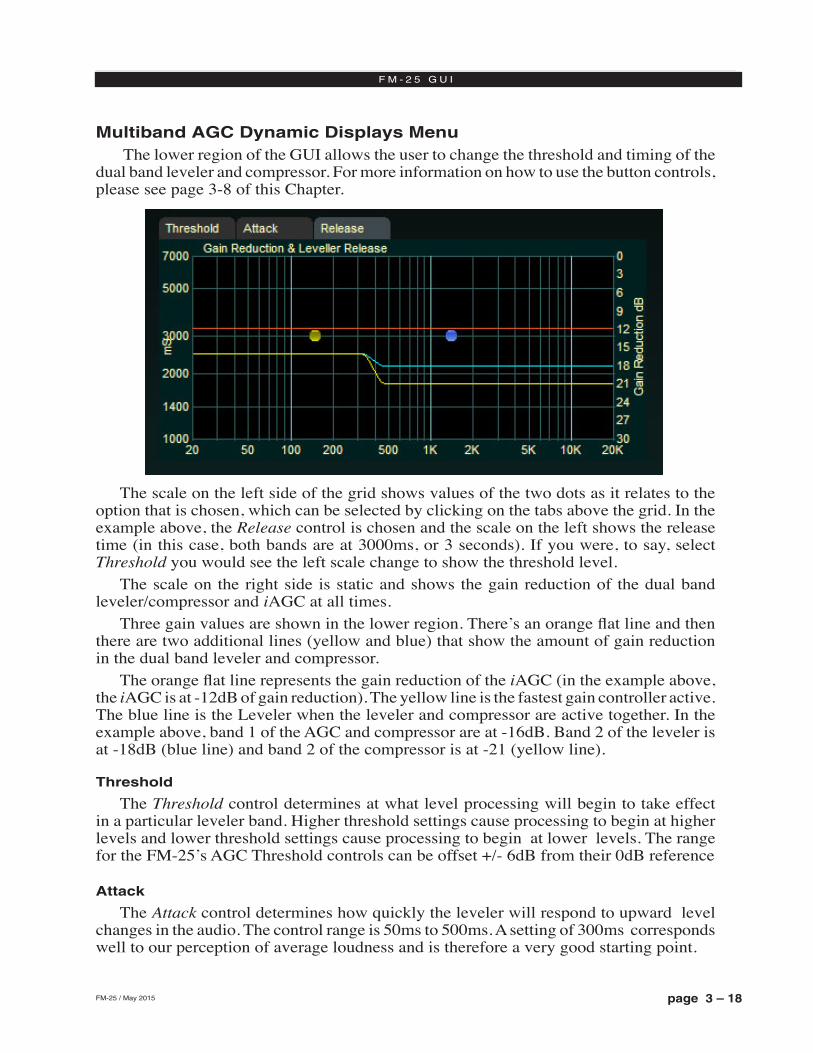
page 3 – 18FM-25 / May 2015
F M - 2 5 G U I
Multiband AGC Dynamic Displays Menu The lower region of the GUI allows the user to change the threshold and timing of the
dual band leveler and compressor. For more information on how to use the button controls, please see page 3‑8 of this Chapter.
The scale on the left side of the grid shows values of the two dots as it relates to the option that is chosen, which can be selected by clicking on the tabs above the grid. In the example above, the Release control is chosen and the scale on the left shows the release time (in this case, both bands are at 3000ms, or 3 seconds). If you were, to say, select Threshold you would see the left scale change to show the threshold level.
The scale on the right side is static and shows the gain reduction of the dual band leveler/compressor and iAGC at all times.
Three gain values are shown in the lower region. There’s an orange flat line and then there are two additional lines (yellow and blue) that show the amount of gain reduction in the dual band leveler and compressor.
The orange flat line represents the gain reduction of the iAGC (in the example above, the iAGC is at ‑12dB of gain reduction). The yellow line is the fastest gain controller active. The blue line is the Leveler when the leveler and compressor are active together. In the example above, band 1 of the AGC and compressor are at ‑16dB. Band 2 of the leveler is at ‑18dB (blue line) and band 2 of the compressor is at ‑21 (yellow line).
Threshold
The Threshold control determines at what level processing will begin to take effect in a particular leveler band. Higher threshold settings cause processing to begin at higher levels and lower threshold settings cause processing to begin at lower levels. The range for the FM‑25’s AGC Threshold controls can be offset +/‑ 6dB from their 0dB reference
Attack
The Attack control determines how quickly the leveler will respond to upward level changes in the audio. The control range is 50ms to 500ms. A setting of 300ms corresponds well to our perception of average loudness and is therefore a very good starting point.
page 3 – 19FM-25 / May 2015
F M - 2 5 G U I
Release
The Release control determines the rate at which the leveler will increase gain when the audio levels fall, as long as they are still above the Gate Threshold setting discussed previously. The adjustment range of the control is from 1.0 seconds to 7.0 seconds. The 7 second setting is considered VERY slow and is recommended for fine‑arts or classical programming. The 1 second setting is very fast and is recommended only if a certain “pumpy” texture is desired. The recommended setting for most formats is between 2.5 seconds and 6 seconds.
Neither the Compressor or iAGC have any user adjustable attack and release times. Those adjustments are computed automatically and change depending on
source material and the settings of the leveler.
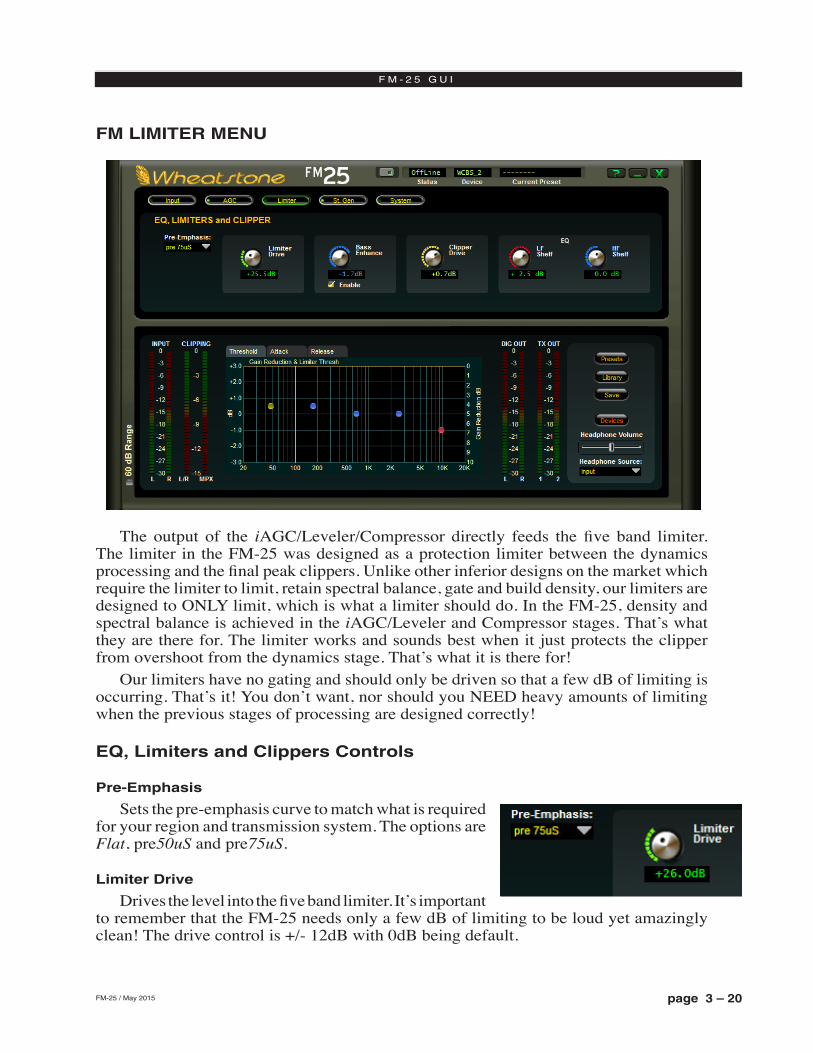
page 3 – 20FM-25 / May 2015
F M - 2 5 G U I
FM LIMITER MENU
The output of the iAGC/Leveler/Compressor directly feeds the five band limiter. The limiter in the FM‑25 was designed as a protection limiter between the dynamics processing and the final peak clippers. Unlike other inferior designs on the market which require the limiter to limit, retain spectral balance, gate and build density, our limiters are designed to ONLY limit, which is what a limiter should do. In the FM‑25, density and spectral balance is achieved in the iAGC/Leveler and Compressor stages. That’s what they are there for. The limiter works and sounds best when it just protects the clipper from overshoot from the dynamics stage. That’s what it is there for!
Our limiters have no gating and should only be driven so that a few dB of limiting is occurring. That’s it! You don’t want, nor should you NEED heavy amounts of limiting when the previous stages of processing are designed correctly!
EQ, Limiters and Clippers Controls
Pre-Emphasis
Sets the pre‑emphasis curve to match what is required for your region and transmission system. The options are Flat, pre50uS and pre75uS.
Limiter Drive
Drives the level into the five band limiter. It’s important to remember that the FM‑25 needs only a few dB of limiting to be loud yet amazingly clean! The drive control is +/‑ 12dB with 0dB being default.
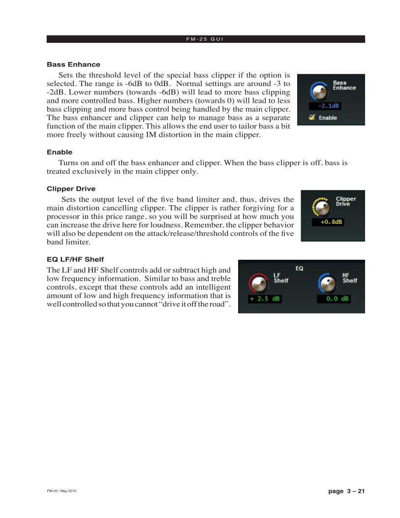
page 3 – 21FM-25 / May 2015
F M - 2 5 G U I
Bass Enhance
Sets the threshold level of the special bass clipper if the option is selected. The range is ‑6dB to 0dB. Normal settings are around ‑3 to ‑2dB. Lower numbers (towards ‑6dB) will lead to more bass clipping and more controlled bass. Higher numbers (towards 0) will lead to less bass clipping and more bass control being handled by the main clipper. The bass enhancer and clipper can help to manage bass as a separate function of the main clipper. This allows the end user to tailor bass a bit more freely without causing IM distortion in the main clipper.
Enable
Turns on and off the bass enhancer and clipper. When the bass clipper is off, bass is treated exclusively in the main clipper only.
Clipper Drive
Sets the output level of the five band limiter and, thus, drives the main distortion cancelling clipper. The clipper is rather forgiving for a processor in this price range, so you will be surprised at how much you can increase the drive here for loudness. Remember, the clipper behavior will also be dependent on the attack/release/threshold controls of the five band limiter.
EQ LF/HF Shelf
The LF and HF Shelf controls add or subtract high and low frequency information. Similar to bass and treble controls, except that these controls add an intelligent amount of low and high frequency information that is well controlled so that you cannot “drive it off the road”.
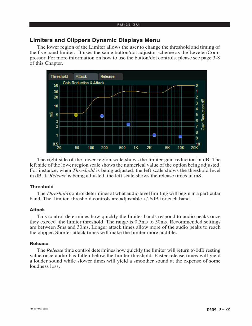
page 3 – 22FM-25 / May 2015
F M - 2 5 G U I
Limiters and Clippers Dynamic Displays MenuThe lower region of the Limiter allows the user to change the threshold and timing of
the five band limiter. It uses the same button/dot adjustor scheme as the Leveler/Com‑pressor. For more information on how to use the button/dot controls, please see page 3‑8 of this Chapter.
The right side of the lower region scale shows the limiter gain reduction in dB. The left side of the lower region scale shows the numerical value of the option being adjusted. For instance, when Threshold is being adjusted, the left scale shows the threshold level in dB. If Release is being adjusted, the left scale shows the release times in mS.
Threshold
The Threshold control determines at what audio level limiting will begin in a particular band. The limiter threshold controls are adjustable +/‑6dB for each band.
Attack
This control determines how quickly the limiter bands respond to audio peaks once they exceed the limiter threshold. The range is 0.5ms to 50ms. Recommended settings are between 5ms and 30ms. Longer attack times allow more of the audio peaks to reach the clipper. Shorter attack times will make the limiter more audible.
Release
The Release time control determines how quickly the limiter will return to 0dB resting value once audio has fallen below the limiter threshold. Faster release times will yield a louder sound while slower times will yield a smoother sound at the expense of some loudness loss.
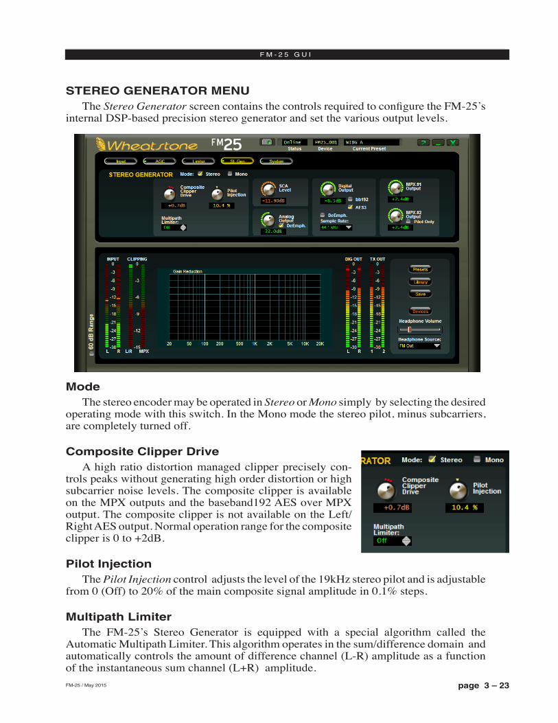
page 3 – 23FM-25 / May 2015
F M - 2 5 G U I
STEREO GENERATOR MENUThe Stereo Generator screen contains the controls required to configure the FM‑25’s
internal DSP‑based precision stereo generator and set the various output levels.
ModeThe stereo encoder may be operated in Stereo or Mono simply by selecting the desired
operating mode with this switch. In the Mono mode the stereo pilot, minus subcarriers, are completely turned off.
Composite Clipper DriveA high ratio distortion managed clipper precisely con‑
trols peaks without generating high order distortion or high subcarrier noise levels. The composite clipper is available on the MPX outputs and the baseband192 AES over MPX output. The composite clipper is not available on the Left/Right AES output. Normal operation range for the composite clipper is 0 to +2dB.
Pilot InjectionThe Pilot Injection control adjusts the level of the 19kHz stereo pilot and is adjustable
from 0 (Off) to 20% of the main composite signal amplitude in 0.1% steps.
Multipath Limiter The FM‑25’s Stereo Generator is equipped with a special algorithm called the
Automatic Multipath Limiter. This algorithm operates in the sum/difference domain and automatically controls the amount of difference channel (L‑R) amplitude as a function of the instantaneous sum channel (L+R) amplitude.
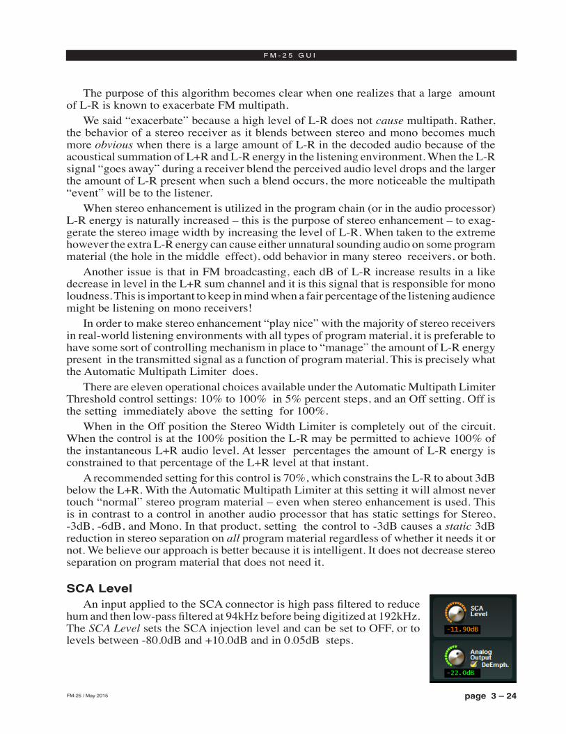
page 3 – 24FM-25 / May 2015
F M - 2 5 G U I
The purpose of this algorithm becomes clear when one realizes that a large amount of L‑R is known to exacerbate FM multipath.
We said “exacerbate” because a high level of L‑R does not cause multipath. Rather, the behavior of a stereo receiver as it blends between stereo and mono becomes much more obvious when there is a large amount of L‑R in the decoded audio because of the acoustical summation of L+R and L‑R energy in the listening environment. When the L‑R signal “goes away” during a receiver blend the perceived audio level drops and the larger the amount of L‑R present when such a blend occurs, the more noticeable the multipath “event” will be to the listener.
When stereo enhancement is utilized in the program chain (or in the audio processor) L‑R energy is naturally increased – this is the purpose of stereo enhancement – to exag‑gerate the stereo image width by increasing the level of L‑R. When taken to the extreme however the extra L‑R energy can cause either unnatural sounding audio on some program material (the hole in the middle effect), odd behavior in many stereo receivers, or both.
Another issue is that in FM broadcasting, each dB of L‑R increase results in a like decrease in level in the L+R sum channel and it is this signal that is responsible for mono loudness. This is important to keep in mind when a fair percentage of the listening audience might be listening on mono receivers!
In order to make stereo enhancement “play nice” with the majority of stereo receivers in real‑world listening environments with all types of program material, it is preferable to have some sort of controlling mechanism in place to “manage” the amount of L‑R energy present in the transmitted signal as a function of program material. This is precisely what the Automatic Multipath Limiter does.
There are eleven operational choices available under the Automatic Multipath Limiter Threshold control settings: 10% to 100% in 5% percent steps, and an Off setting. Off is the setting immediately above the setting for 100%.
When in the Off position the Stereo Width Limiter is completely out of the circuit. When the control is at the 100% position the L‑R may be permitted to achieve 100% of the instantaneous L+R audio level. At lesser percentages the amount of L‑R energy is constrained to that percentage of the L+R level at that instant.
A recommended setting for this control is 70%, which constrains the L‑R to about 3dB below the L+R. With the Automatic Multipath Limiter at this setting it will almost never touch “normal” stereo program material – even when stereo enhancement is used. This is in contrast to a control in another audio processor that has static settings for Stereo, ‑3dB, ‑6dB, and Mono. In that product, setting the control to ‑3dB causes a static 3dB reduction in stereo separation on all program material regardless of whether it needs it or not. We believe our approach is better because it is intelligent. It does not decrease stereo separation on program material that does not need it.
SCA LevelAn input applied to the SCA connector is high pass filtered to reduce
hum and then low‑pass filtered at 94kHz before being digitized at 192kHz. The SCA Level sets the SCA injection level and can be set to OFF, or to levels between ‑80.0dB and +10.0dB and in 0.05dB steps.
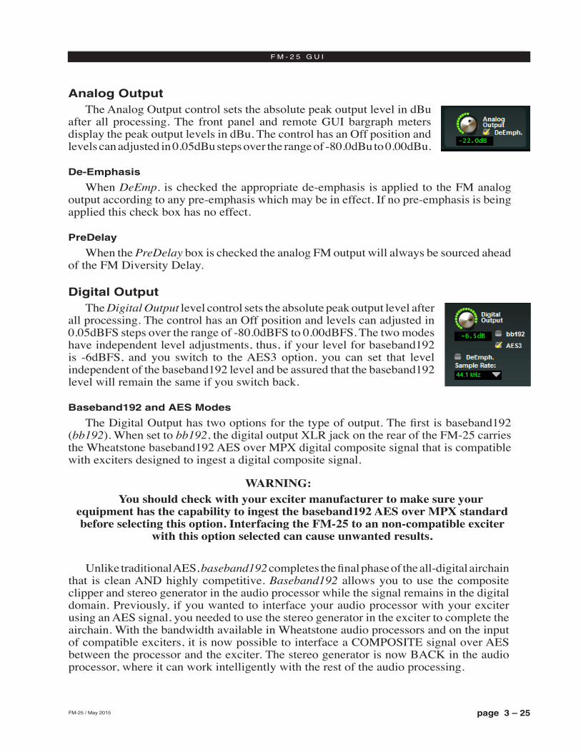
page 3 – 25FM-25 / May 2015
F M - 2 5 G U I
Analog OutputThe Analog Output control sets the absolute peak output level in dBu
after all processing. The front panel and remote GUI bargraph meters display the peak output levels in dBu. The control has an Off position and levels can adjusted in 0.05dBu steps over the range of ‑80.0dBu to 0.00dBu.
De-Emphasis
When DeEmp. is checked the appropriate de‑emphasis is applied to the FM analog output according to any pre‑emphasis which may be in effect. If no pre‑emphasis is being applied this check box has no effect.
PreDelay
When the PreDelay box is checked the analog FM output will always be sourced ahead of the FM Diversity Delay.
Digital OutputThe Digital Output level control sets the absolute peak output level after
all processing. The control has an Off position and levels can adjusted in 0.05dBFS steps over the range of ‑80.0dBFS to 0.00dBFS. The two modes have independent level adjustments, thus, if your level for baseband192 is ‑6dBFS, and you switch to the AES3 option, you can set that level independent of the baseband192 level and be assured that the baseband192 level will remain the same if you switch back.
Baseband192 and AES Modes
The Digital Output has two options for the type of output. The first is baseband192 (bb192). When set to bb192, the digital output XLR jack on the rear of the FM‑25 carries the Wheatstone baseband192 AES over MPX digital composite signal that is compatible with exciters designed to ingest a digital composite signal.
WARNING: You should check with your exciter manufacturer to make sure your
equipment has the capability to ingest the baseband192 AES over MPX standard before selecting this option. Interfacing the FM‑25 to an non‑compatible exciter
with this option selected can cause unwanted results.
Unlike traditional AES, baseband192 completes the final phase of the all‑digital airchain that is clean AND highly competitive. Baseband192 allows you to use the composite clipper and stereo generator in the audio processor while the signal remains in the digital domain. Previously, if you wanted to interface your audio processor with your exciter using an AES signal, you needed to use the stereo generator in the exciter to complete the airchain. With the bandwidth available in Wheatstone audio processors and on the input of compatible exciters, it is now possible to interface a COMPOSITE signal over AES between the processor and the exciter. The stereo generator is now BACK in the audio processor, where it can work intelligently with the rest of the audio processing.
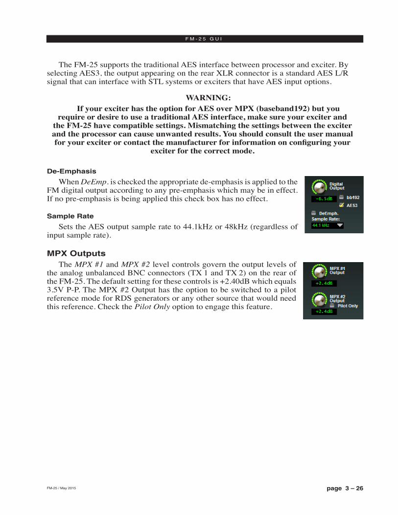
page 3 – 26FM-25 / May 2015
F M - 2 5 G U I
The FM‑25 supports the traditional AES interface between processor and exciter. By selecting AES3, the output appearing on the rear XLR connector is a standard AES L/R signal that can interface with STL systems or exciters that have AES input options.
WARNING: If your exciter has the option for AES over MPX (baseband192) but you
require or desire to use a traditional AES interface, make sure your exciter and the FM‑25 have compatible settings. Mismatching the settings between the exciter and the processor can cause unwanted results. You should consult the user manual for your exciter or contact the manufacturer for information on configuring your
exciter for the correct mode.
De-Emphasis
When DeEmp. is checked the appropriate de‑emphasis is applied to the FM digital output according to any pre‑emphasis which may be in effect. If no pre‑emphasis is being applied this check box has no effect.
Sample Rate
Sets the AES output sample rate to 44.1kHz or 48kHz (regardless of input sample rate).
MPX OutputsThe MPX #1 and MPX #2 level controls govern the output levels of
the analog unbalanced BNC connectors (TX 1 and TX 2) on the rear of the FM‑25. The default setting for these controls is +2.40dB which equals 3.5V P‑P. The MPX #2 Output has the option to be switched to a pilot reference mode for RDS generators or any other source that would need this reference. Check the Pilot Only option to engage this feature.
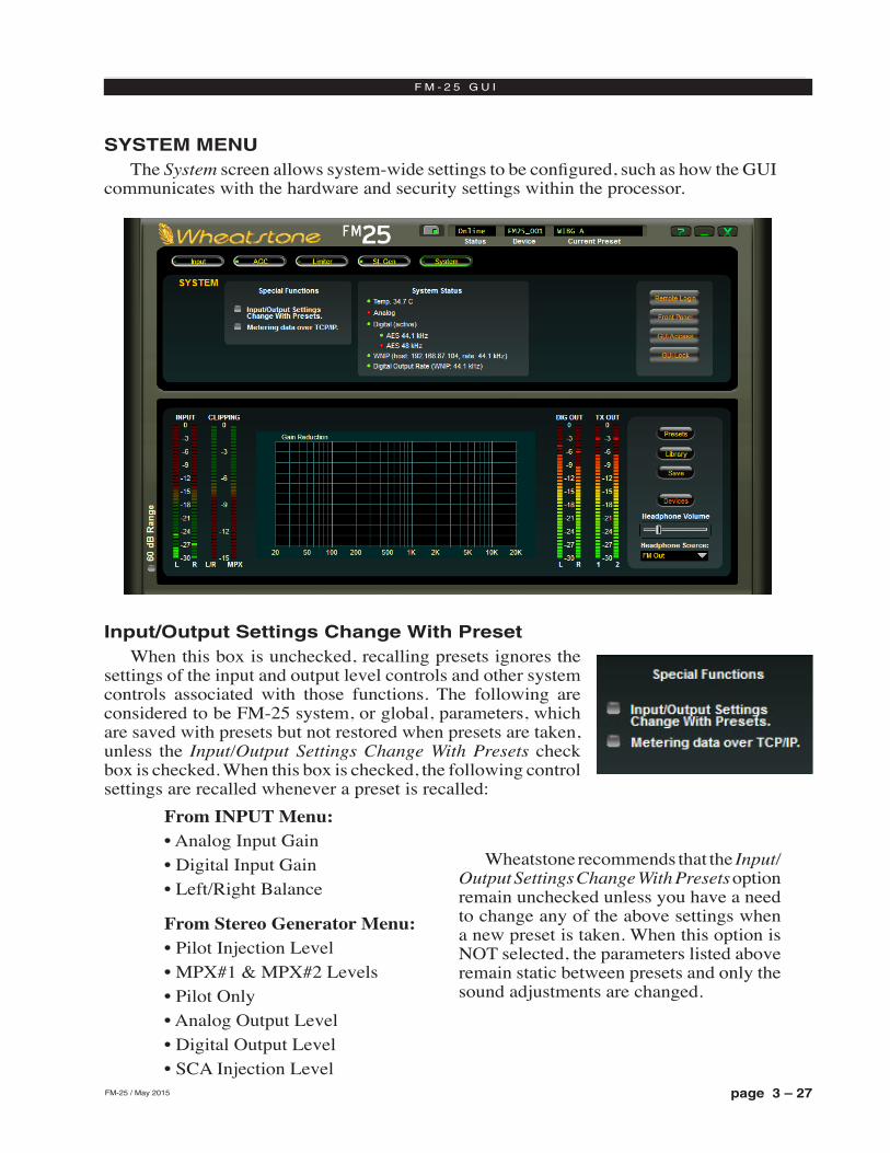
page 3 – 27FM-25 / May 2015
F M - 2 5 G U I
SYSTEM MENUThe System screen allows system‑wide settings to be configured, such as how the GUI
communicates with the hardware and security settings within the processor.
Input/Output Settings Change With PresetWhen this box is unchecked, recalling presets ignores the
settings of the input and output level controls and other system controls associated with those functions. The following are considered to be FM‑25 system, or global, parameters, which are saved with presets but not restored when presets are taken, unless the Input/Output Settings Change With Presets check box is checked. When this box is checked, the following control settings are recalled whenever a preset is recalled:
Wheatstone recommends that the Input/Output Settings Change With Presets option remain unchecked unless you have a need to change any of the above settings when a new preset is taken. When this option is NOT selected, the parameters listed above remain static between presets and only the sound adjustments are changed.
From INPUT Menu:• Analog Input Gain• Digital Input Gain• Left/Right Balance
From Stereo Generator Menu:• Pilot Injection Level• MPX#1 & MPX#2 Levels• Pilot Only• Analog Output Level• Digital Output Level• SCA Injection Level
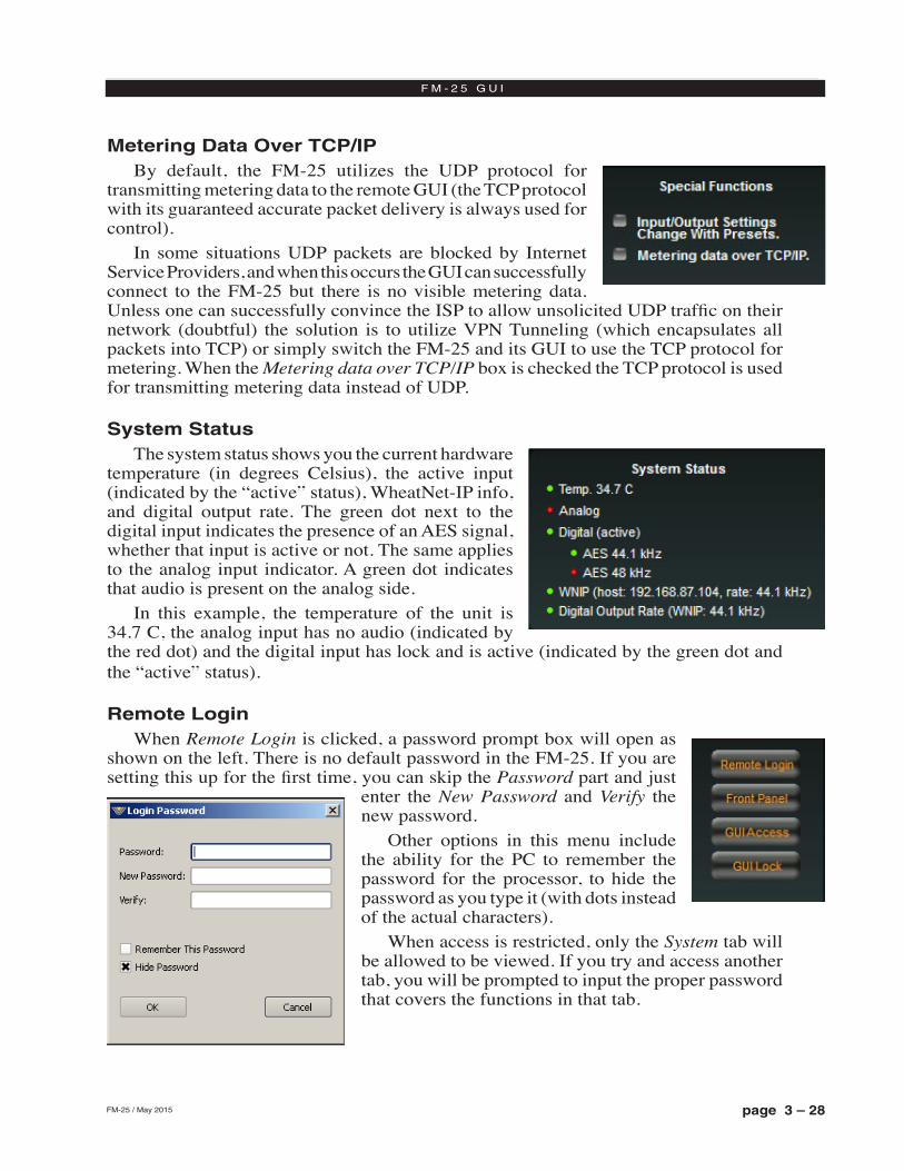
page 3 – 28FM-25 / May 2015
F M - 2 5 G U I
Metering Data Over TCP/IPBy default, the FM‑25 utilizes the UDP protocol for
transmitting metering data to the remote GUI (the TCP protocol with its guaranteed accurate packet delivery is always used for control).
In some situations UDP packets are blocked by Internet Service Providers, and when this occurs the GUI can successfully connect to the FM‑25 but there is no visible metering data. Unless one can successfully convince the ISP to allow unsolicited UDP traffic on their network (doubtful) the solution is to utilize VPN Tunneling (which encapsulates all packets into TCP) or simply switch the FM‑25 and its GUI to use the TCP protocol for metering. When the Metering data over TCP/IP box is checked the TCP protocol is used for transmitting metering data instead of UDP.
System StatusThe system status shows you the current hardware
temperature (in degrees Celsius), the active input (indicated by the “active” status), WheatNet‑IP info, and digital output rate. The green dot next to the digital input indicates the presence of an AES signal, whether that input is active or not. The same applies to the analog input indicator. A green dot indicates that audio is present on the analog side.
In this example, the temperature of the unit is 34.7 C, the analog input has no audio (indicated by the red dot) and the digital input has lock and is active (indicated by the green dot and the “active” status).
Remote LoginWhen Remote Login is clicked, a password prompt box will open as
shown on the left. There is no default password in the FM‑25. If you are setting this up for the first time, you can skip the Password part and just
enter the New Password and Verify the new password.
Other options in this menu include the ability for the PC to remember the password for the processor, to hide the password as you type it (with dots instead of the actual characters).
When access is restricted, only the System tab will be allowed to be viewed. If you try and access another tab, you will be prompted to input the proper password that covers the functions in that tab.
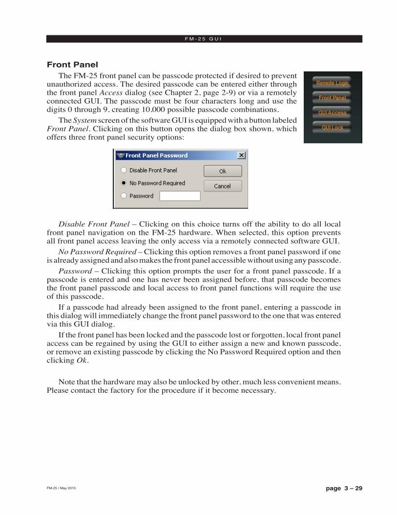
page 3 – 29FM-25 / May 2015
F M - 2 5 G U I
Front PanelThe FM‑25 front panel can be passcode protected if desired to prevent
unauthorized access. The desired passcode can be entered either through the front panel Access dialog (see Chapter 2, page 2‑9) or via a remotely connected GUI. The passcode must be four characters long and use the digits 0 through 9, creating 10,000 possible passcode combinations.
The System screen of the software GUI is equipped with a button labeled Front Panel. Clicking on this button opens the dialog box shown, which offers three front panel security options:
Disable Front Panel – Clicking on this choice turns off the ability to do all local front panel navigation on the FM‑25 hardware. When selected, this option prevents all front panel access leaving the only access via a remotely connected software GUI.
No Password Required – Clicking this option removes a front panel password if one is already assigned and also makes the front panel accessible without using any passcode.
Password – Clicking this option prompts the user for a front panel passcode. If a passcode is entered and one has never been assigned before, that passcode becomes the front panel passcode and local access to front panel functions will require the use of this passcode.
If a passcode had already been assigned to the front panel, entering a passcode in this dialog will immediately change the front panel password to the one that was entered via this GUI dialog.
If the front panel has been locked and the passcode lost or forgotten, local front panel access can be regained by using the GUI to either assign a new and known passcode, or remove an existing passcode by clicking the No Password Required option and then clicking Ok.
Note that the hardware may also be unlocked by other, much less convenient means. Please contact the factory for the procedure if it become necessary.
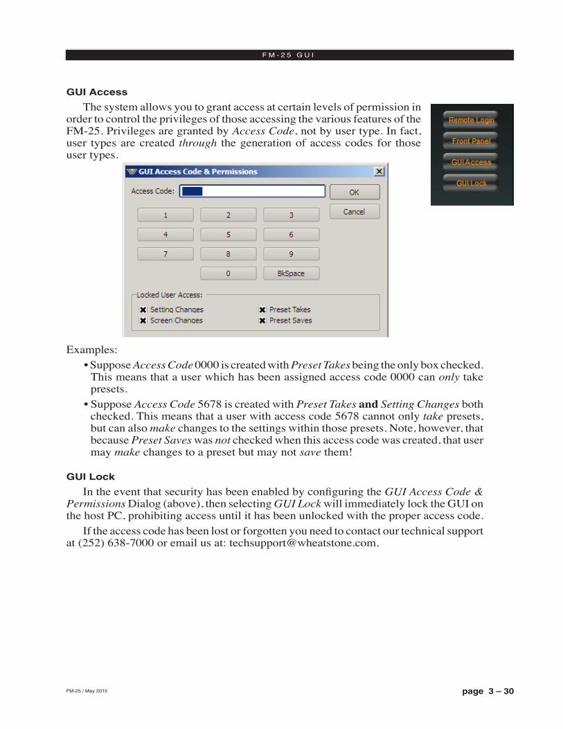
page 3 – 30FM-25 / May 2015
F M - 2 5 G U I
GUI Access
The system allows you to grant access at certain levels of permission in order to control the privileges of those accessing the various features of the FM‑25. Privileges are granted by Access Code, not by user type. In fact, user types are created through the generation of access codes for those user types.
Examples:• Suppose Access Code 0000 is created with Preset Takes being the only box checked.
This means that a user which has been assigned access code 0000 can only take presets.
• Suppose Access Code 5678 is created with Preset Takes and Setting Changes both checked. This means that a user with access code 5678 cannot only take presets, but can also make changes to the settings within those presets. Note, however, that because Preset Saves was not checked when this access code was created, that user may make changes to a preset but may not save them!
GUI Lock
In the event that security has been enabled by configuring the GUI Access Code & Permissions Dialog (above), then selecting GUI Lock will immediately lock the GUI on the host PC, prohibiting access until it has been unlocked with the proper access code.
If the access code has been lost or forgotten you need to contact our technical support at (252) 638‑7000 or email us at: [email protected].
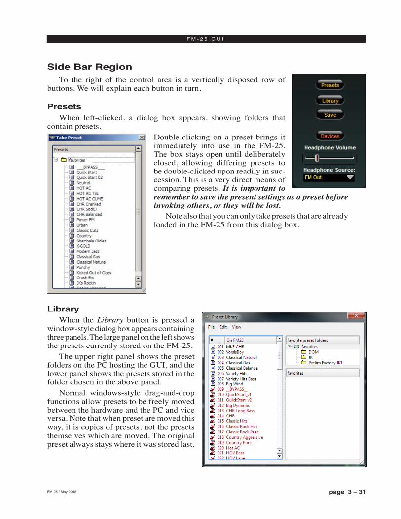
page 3 – 31FM-25 / May 2015
F M - 2 5 G U I
Side Bar RegionTo the right of the control area is a vertically disposed row of
buttons. We will explain each button in turn.
PresetsWhen left‑clicked, a dialog box appears, showing folders that
contain presets. Double‑clicking on a preset brings it immediately into use in the FM‑25. The box stays open until deliberately closed, allowing differing presets to be double‑clicked upon readily in suc‑cession. This is a very direct means of comparing presets. It is important to remember to save the present settings as a preset before invoking others, or they will be lost.
Note also that you can only take presets that are already loaded in the FM‑25 from this dialog box.
LibraryWhen the Library button is pressed a
window‑style dialog box appears containing three panels. The large panel on the left shows the presets currently stored on the FM‑25.
The upper right panel shows the preset folders on the PC hosting the GUI, and the lower panel shows the presets stored in the folder chosen in the above panel.
Normal windows‑style drag‑and‑drop functions allow presets to be freely moved between the hardware and the PC and vice versa. Note that when preset are moved this way, it is copies of presets, not the presets themselves which are moved. The original preset always stays where it was stored last.
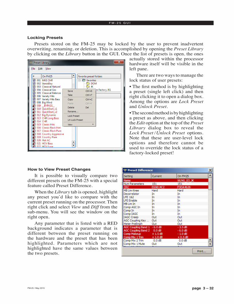
page 3 – 32FM-25 / May 2015
F M - 2 5 G U I
Locking Presets
Presets stored on the FM‑25 may be locked by the user to prevent inadvertent overwriting, renaming, or deletion. This is accomplished by opening the Preset Library by clicking on the Library button in the GUI. Once the list of presets is open, the ones
actually stored within the processor hardware itself will be visible in the left pane.
There are two ways to manage the lock status of user presets:• The first method is by highlighting a preset (single left click) and then right clicking it to open a dialog box. Among the options are Lock Preset and Unlock Preset.• The second method is by highlighting a preset as above, and then clicking the Edit option at the top of the Preset Library dialog box to reveal the Lock Preset /Unlock Preset options. Note that these are user‑level lock options and therefore cannot be used to override the lock status of a factory‑locked preset!
How to View Preset Changes
It is possible to visually compare two different presets on the FM‑25 with a special feature called Preset Difference.
When the Library tab is opened, highlight any preset you’d like to compare with the current preset running on the processor. Then right click and select View and Diff from the sub‑menu. You will see the window on the right open.
Any parameter that is listed with a RED background indicates a parameter that is different between the preset running on the hardware and the preset that has been highlighted. Parameters which are not highlighted have the same values between the two presets.
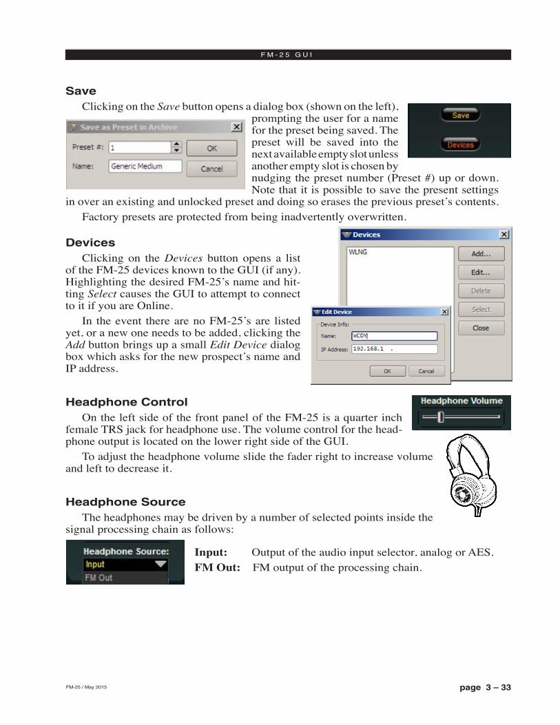
page 3 – 33FM-25 / May 2015
F M - 2 5 G U I
SaveClicking on the Save button opens a dialog box (shown on the left),
prompting the user for a name for the preset being saved. The preset will be saved into the next available empty slot unless another empty slot is chosen by nudging the preset number (Preset #) up or down. Note that it is possible to save the present settings
in over an existing and unlocked preset and doing so erases the previous preset’s contents. Factory presets are protected from being inadvertently overwritten.
DevicesClicking on the Devices button opens a list
of the FM‑25 devices known to the GUI (if any). Highlighting the desired FM‑25’s name and hit‑ting Select causes the GUI to attempt to connect to it if you are Online.
In the event there are no FM‑25’s are listed yet, or a new one needs to be added, clicking the Add button brings up a small Edit Device dialog box which asks for the new prospect’s name and IP address.
Headphone ControlOn the left side of the front panel of the FM‑25 is a quarter inch
female TRS jack for headphone use. The volume control for the head‑phone output is located on the lower right side of the GUI.
To adjust the headphone volume slide the fader right to increase volume and left to decrease it.
Headphone SourceThe headphones may be driven by a number of selected points inside the
signal processing chain as follows:
Input: Output of the audio input selector, analog or AES.FM Out: FM output of the processing chain.
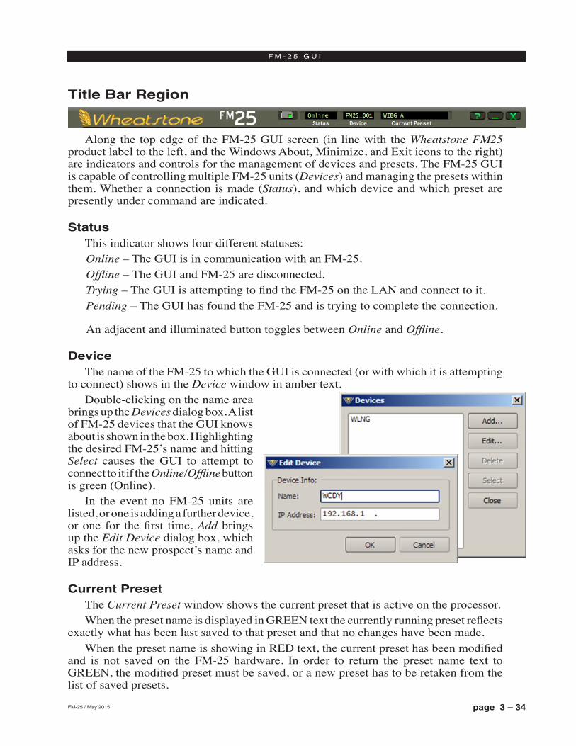
page 3 – 34FM-25 / May 2015
F M - 2 5 G U I
Title Bar Region
Along the top edge of the FM‑25 GUI screen (in line with the Wheatstone FM25 product label to the left, and the Windows About, Minimize, and Exit icons to the right) are indicators and controls for the management of devices and presets. The FM‑25 GUI is capable of controlling multiple FM‑25 units (Devices) and managing the presets within them. Whether a connection is made (Status), and which device and which preset are presently under command are indicated.
StatusThis indicator shows four different statuses:Online – The GUI is in communication with an FM‑25.Offline – The GUI and FM‑25 are disconnected. Trying – The GUI is attempting to find the FM‑25 on the LAN and connect to it.Pending – The GUI has found the FM‑25 and is trying to complete the connection.
An adjacent and illuminated button toggles between Online and Offline.
DeviceThe name of the FM‑25 to which the GUI is connected (or with which it is attempting
to connect) shows in the Device window in amber text.Double‑clicking on the name area
brings up the Devices dialog box. A list of FM‑25 devices that the GUI knows about is shown in the box. Highlighting the desired FM‑25’s name and hitting Select causes the GUI to attempt to connect to it if the Online/Offline button is green (Online).
In the event no FM‑25 units are listed, or one is adding a further device, or one for the first time, Add brings up the Edit Device dialog box, which asks for the new prospect’s name and IP address.
Current PresetThe Current Preset window shows the current preset that is active on the processor. When the preset name is displayed in GREEN text the currently running preset reflects
exactly what has been last saved to that preset and that no changes have been made. When the preset name is showing in RED text, the current preset has been modified
and is not saved on the FM‑25 hardware. In order to return the preset name text to GREEN, the modified preset must be saved, or a new preset has to be retaken from the list of saved presets.
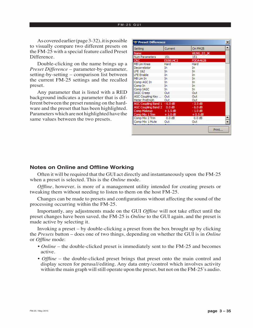
page 3 – 35FM-25 / May 2015
F M - 2 5 G U I
As covered earlier (page 3‑32), it is possible to visually compare two different presets on the FM‑25 with a special feature called Preset Difference.
Double‑clicking on the name brings up a Preset Difference – parameter‑by‑parameter, setting‑by‑setting – comparison list between the current FM‑25 settings and the recalled preset.
Any parameter that is listed with a RED background indicates a parameter that is dif‑ferent between the preset running on the hard‑ware and the preset that has been highlighted. Parameters which are not highlighted have the same values between the two presets.
Notes on Online and Offline WorkingOften it will be required that the GUI act directly and instantaneously upon the FM‑25
when a preset is selected. This is the Online mode.Offline, however, is more of a management utility intended for creating presets or
tweaking them without needing to listen to them on the host FM‑25.Changes can be made to presets and configurations without affecting the sound of the
processing occurring within the FM‑25.Importantly, any adjustments made on the GUI Offline will not take effect until the
preset changes have been saved, the FM‑25 is Online to the GUI again, and the preset is made active by selecting it.
Invoking a preset – by double‑clicking a preset from the box brought up by clicking the Presets button – does one of two things, depending on whether the GUI is in Online or Offline mode:
• Online – the double‑clicked preset is immediately sent to the FM‑25 and becomes active.
• Offline – the double‑clicked preset brings that preset onto the main control and display screen for perusal/editing. Any data entry/control which involves activity within the main graph will still operate upon the preset, but not on the FM‑25’s audio.
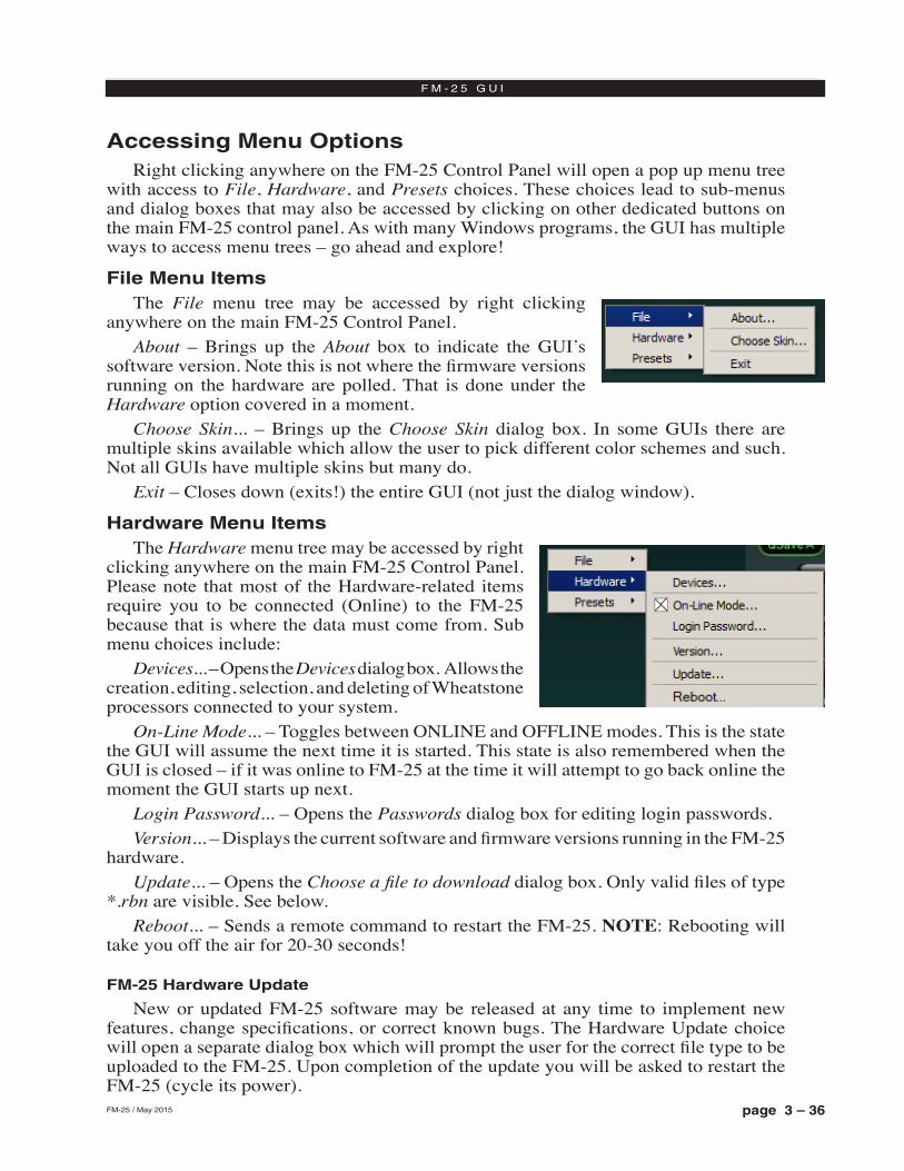
page 3 – 36FM-25 / May 2015
F M - 2 5 G U I
Accessing Menu OptionsRight clicking anywhere on the FM‑25 Control Panel will open a pop up menu tree
with access to File, Hardware, and Presets choices. These choices lead to sub‑menus and dialog boxes that may also be accessed by clicking on other dedicated buttons on the main FM‑25 control panel. As with many Windows programs, the GUI has multiple ways to access menu trees – go ahead and explore!
File Menu ItemsThe File menu tree may be accessed by right clicking
anywhere on the main FM‑25 Control Panel. About – Brings up the About box to indicate the GUI’s
software version. Note this is not where the firmware versions running on the hardware are polled. That is done under the Hardware option covered in a moment.
Choose Skin... – Brings up the Choose Skin dialog box. In some GUIs there are multiple skins available which allow the user to pick different color schemes and such. Not all GUIs have multiple skins but many do.
Exit – Closes down (exits!) the entire GUI (not just the dialog window).
Hardware Menu ItemsThe Hardware menu tree may be accessed by right
clicking anywhere on the main FM‑25 Control Panel. Please note that most of the Hardware‑related items require you to be connected (Online) to the FM‑25 because that is where the data must come from. Sub menu choices include:
Devices... – Opens the Devices dialog box. Allows the creation, editing, selection, and deleting of Wheatstone processors connected to your system.
On‑Line Mode... – Toggles between ONLINE and OFFLINE modes. This is the state the GUI will assume the next time it is started. This state is also remembered when the GUI is closed – if it was online to FM‑25 at the time it will attempt to go back online the moment the GUI starts up next.
Login Password... – Opens the Passwords dialog box for editing login passwords.Version... – Displays the current software and firmware versions running in the FM‑25
hardware.Update... – Opens the Choose a file to download dialog box. Only valid files of type
*.rbn are visible. See below.Reboot... – Sends a remote command to restart the FM‑25. NOTE: Rebooting will
take you off the air for 20‑30 seconds!
FM-25 Hardware Update
New or updated FM‑25 software may be released at any time to implement new features, change specifications, or correct known bugs. The Hardware Update choice will open a separate dialog box which will prompt the user for the correct file type to be uploaded to the FM‑25. Upon completion of the update you will be asked to restart the FM‑25 (cycle its power).
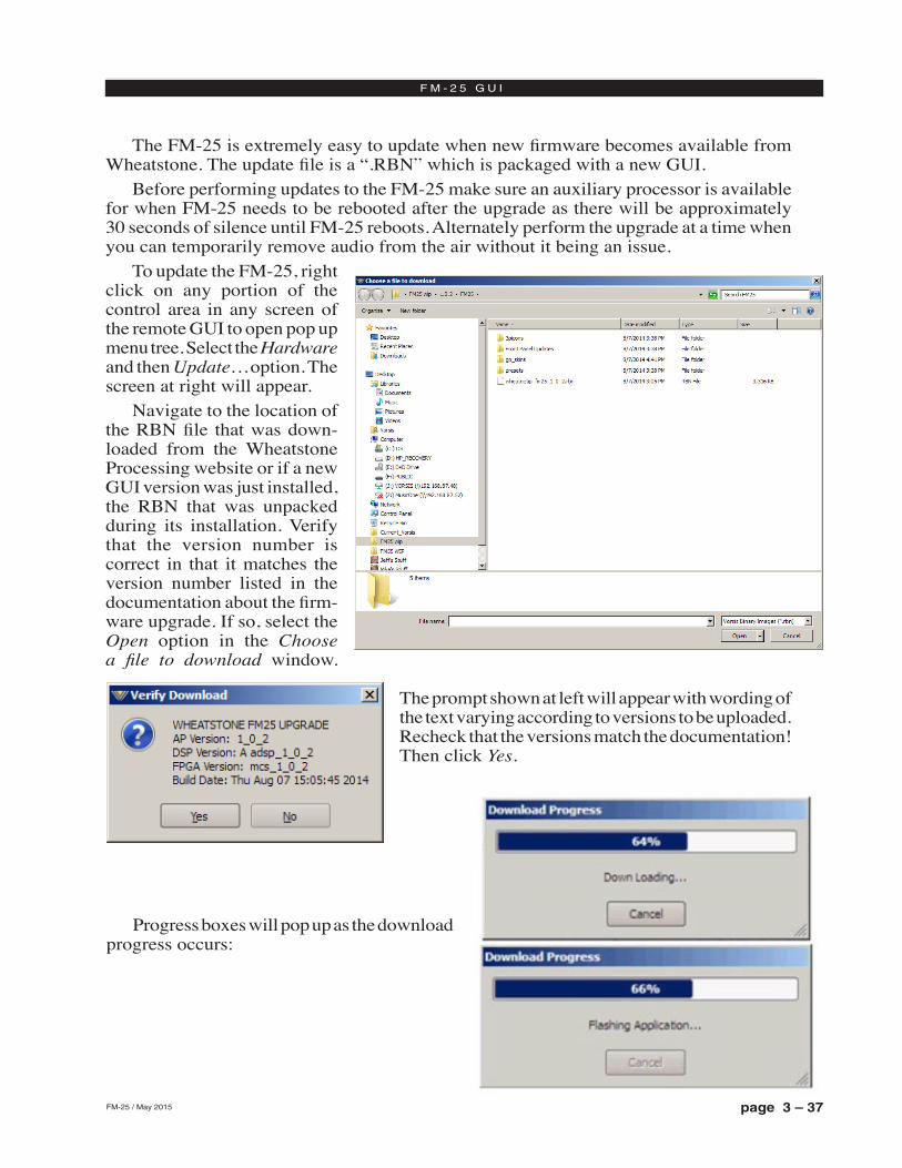
page 3 – 37FM-25 / May 2015
F M - 2 5 G U I
The FM‑25 is extremely easy to update when new firmware becomes available from Wheatstone. The update file is a “.RBN” which is packaged with a new GUI.
Before performing updates to the FM‑25 make sure an auxiliary processor is available for when FM‑25 needs to be rebooted after the upgrade as there will be approximately 30 seconds of silence until FM‑25 reboots. Alternately perform the upgrade at a time when you can temporarily remove audio from the air without it being an issue.
To update the FM‑25, right click on any portion of the control area in any screen of the remote GUI to open pop up menu tree. Select the Hardware and then Update… option. The screen at right will appear.
Navigate to the location of the RBN file that was down‑loaded from the Wheatstone Processing website or if a new GUI version was just installed, the RBN that was unpacked during its installation. Verify that the version number is correct in that it matches the version number listed in the documentation about the firm‑ware upgrade. If so, select the Open option in the Choose a file to download window.
The prompt shown at left will appear with wording of the text varying according to versions to be uploaded.Recheck that the versions match the documentation! Then click Yes.
Progress boxes will pop up as the download progress occurs:
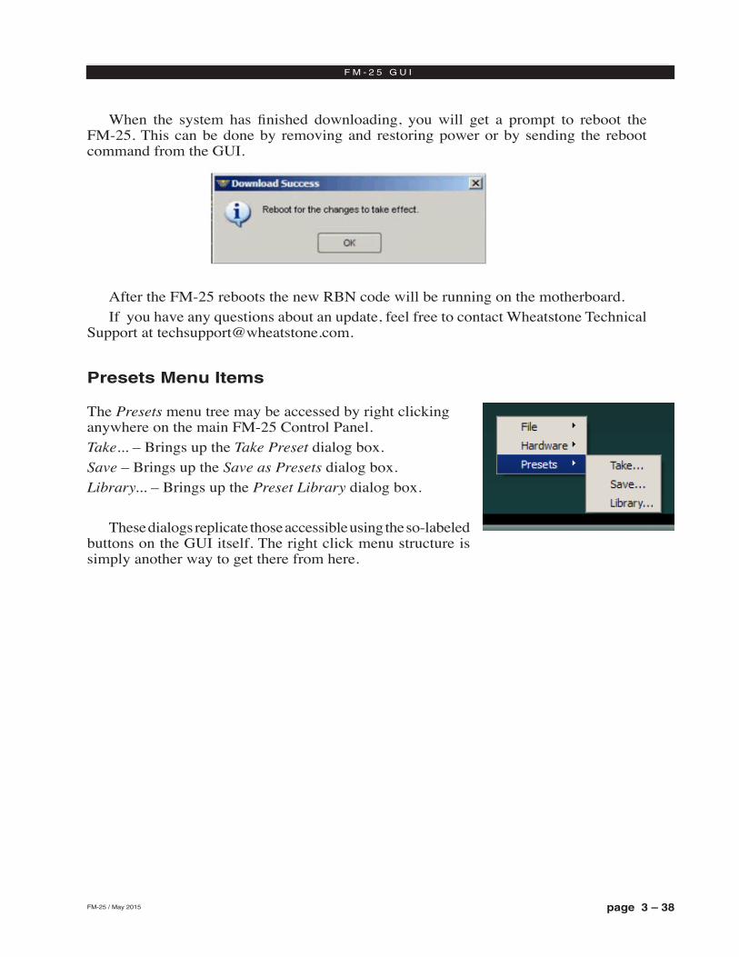
page 3 – 38FM-25 / May 2015
F M - 2 5 G U I
When the system has finished downloading, you will get a prompt to reboot the FM‑25. This can be done by removing and restoring power or by sending the reboot command from the GUI.
After the FM‑25 reboots the new RBN code will be running on the motherboard. If you have any questions about an update, feel free to contact Wheatstone Technical
Support at [email protected].
Presets Menu Items
The Presets menu tree may be accessed by right clicking anywhere on the main FM‑25 Control Panel. Take... – Brings up the Take Preset dialog box. Save – Brings up the Save as Presets dialog box. Library... – Brings up the Preset Library dialog box.
These dialogs replicate those accessible using the so‑labeled buttons on the GUI itself. The right click menu structure is simply another way to get there from here.
page A – 1FM-25 / May 2015
A P P E N D I C E S
Appendices
General Specifications ..................................................................A-3
Interpreting Common Audio Processing Terms .........................A-8Background ................................................................................................................A-8
Audio Terms and Wheatstone Processing .................................................................A-9
Thump/Rumble/Bottom ...........................................................................................A-9
Punch/Boom/Tubby/Warm .....................................................................................A-10
Mud ........................................................................................................................A-10
Honk .......................................................................................................................A-10
Whack ....................................................................................................................A-10
Fuzzy/Tinny ............................................................................................................A-11
Sibilance .................................................................................................................A-11
Treble/Bright/Open .................................................................................................A-11
Finally .....................................................................................................................A-12
WheatNet-IP Configuration ..........................................................A-14Adding FM-25 to The WheatNet-IP System ..............................................................A-14
Appendix A
Appendix B
Appendix C

page A – 2FM-25 / May 2015
A P P E N D I C E S
Appendix A
General Specifications ..................................................................A-3
Contents
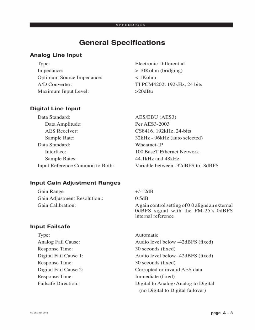
page A – 3FM-25 / May 2015
A P P E N D I C E S
Analog Line Input
Type: Electronic DifferentialImpedance: > 10Kohm (bridging)Optimum Source Impedance: < 1KohmA/D Converter: TI PCM4202. 192kHz, 24 bitsMaximum Input Level: >20dBu
Digital Line Input
Data Standard: AES/EBU (AES3) Data Amplitude: Per AES3-2003 AES Receiver: CS8416, 192kHz, 24-bits Sample Rate: 32kHz - 96kHz (auto selected)Data Standard: Wheatnet-IP Interface: 100 BaseT Ethernet Network Sample Rates: 44.1kHz and 48kHzInput Reference Common to Both: Variable between -32dBFS to -8dBFS
Input Gain Adjustment Ranges
Gain Range +/-12dBGain Adjustment Resolution.: 0.5dBGain Calibration: A gain control setting of 0.0 aligns an external
0dBFS signal with the FM-25’s 0dBFS internal reference
Input Failsafe
Type: AutomaticAnalog Fail Cause: Audio level below -42dBFS (fixed)Response Time: 30 seconds (fixed)Digital Fail Cause 1: Audio level below -42dBFS (fixed)Response Time: 30 seconds (fixed)Digital Fail Cause 2: Corrupted or invalid AES dataResponse Time: Immediate (fixed)Failsafe Direction: Digital to Analog/Analog to Digital (no Digital to Digital failover)
General Specifications
FM-25 / Jan 2018
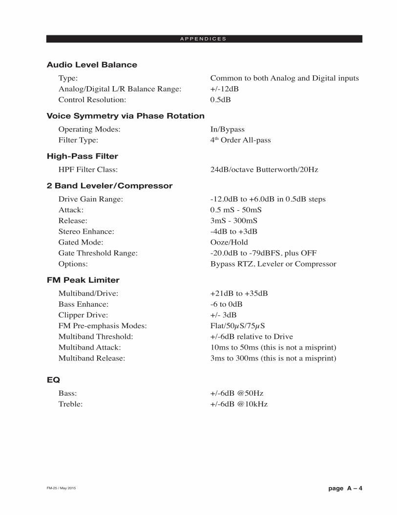
page A – 4FM-25 / May 2015
A P P E N D I C E S
Audio Level Balance
Type: Common to both Analog and Digital inputsAnalog/Digital L/R Balance Range: +/-12dBControl Resolution: 0.5dB
Voice Symmetry via Phase Rotation
Operating Modes: In/Bypass Filter Type: 4th Order All-pass
High-Pass Filter
HPF Filter Class: 24dB/octave Butterworth/20Hz
2 Band Leveler/Compressor
Drive Gain Range: -12.0dB to +6.0dB in 0.5dB stepsAttack: 0.5 mS - 50mS Release: 3mS - 300mSStereo Enhance: -4dB to +3dBGated Mode: Ooze/HoldGate Threshold Range: -20.0dB to -79dBFS, plus OFFOptions: Bypass RTZ, Leveler or Compressor
FM Peak Limiter
Multiband/Drive: +21dB to +35dBBass Enhance: -6 to 0dBClipper Drive: +/- 3dBFM Pre-emphasis Modes: Flat/50µS/75µSMultiband Threshold: +/-6dB relative to DriveMultiband Attack: 10ms to 50ms (this is not a misprint) Multiband Release: 3ms to 300ms (this is not a misprint)
EQ
Bass: +/-6dB @50HzTreble: +/-6dB @10kHz
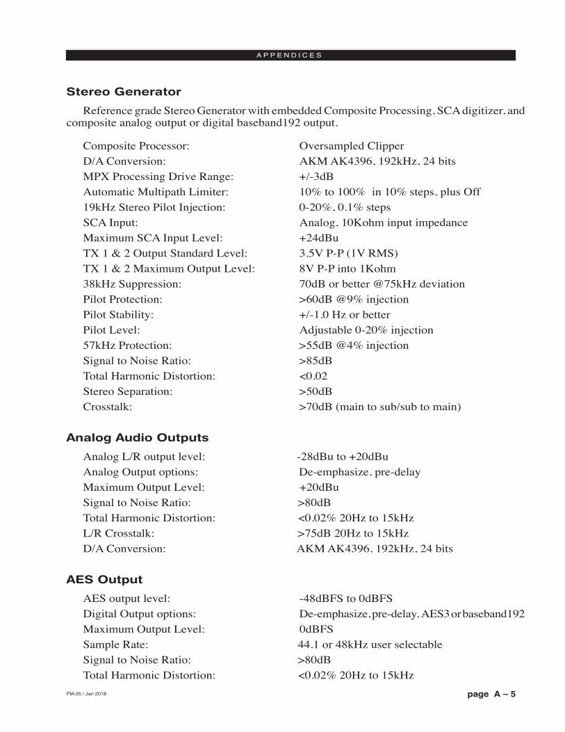
page A – 5FM-25 / May 2015
A P P E N D I C E S
Stereo Generator
Reference grade Stereo Generator with embedded Composite Processing, SCA digitizer, and composite analog output or digital baseband192 output.
Composite Processor: Oversampled Clipper D/A Conversion: AKM AK4396, 192kHz, 24 bits MPX Processing Drive Range: +/-3dBAutomatic Multipath Limiter: 10% to 100% in 10% steps, plus Off19kHz Stereo Pilot Injection: 0-20%, 0.1% stepsSCA Input: Analog, 10Kohm input impedanceMaximum SCA Input Level: +24dBuTX 1 & 2 Output Standard Level: 3.5V P-P (1V RMS)TX 1 & 2 Maximum Output Level: 8V P-P into 1Kohm38kHz Suppression: 70dB or better @75kHz deviationPilot Protection: >60dB @9% injectionPilot Stability: +/-1.0 Hz or betterPilot Level: Adjustable 0-20% injection57kHz Protection: >55dB @4% injectionSignal to Noise Ratio: >85dBTotal Harmonic Distortion: <0.02Stereo Separation: >50dBCrosstalk: >70dB (main to sub/sub to main)
Analog Audio Outputs
Analog L/R output level: -28dBu to +20dBu Analog Output options: De-emphasize, pre-delayMaximum Output Level: +20dBu Signal to Noise Ratio: >80dBTotal Harmonic Distortion: <0.02% 20Hz to 15kHzL/R Crosstalk: >75dB 20Hz to 15kHzD/A Conversion: AKM AK4396, 192kHz, 24 bits
AES Output
AES output level: -48dBFS to 0dBFS Digital Output options: De-emphasize, pre-delay, AES3 or baseband192Maximum Output Level: 0dBFSSample Rate: 44.1 or 48kHz user selectableSignal to Noise Ratio: >80dBTotal Harmonic Distortion: <0.02% 20Hz to 15kHz
FM-25 / Jan 2018
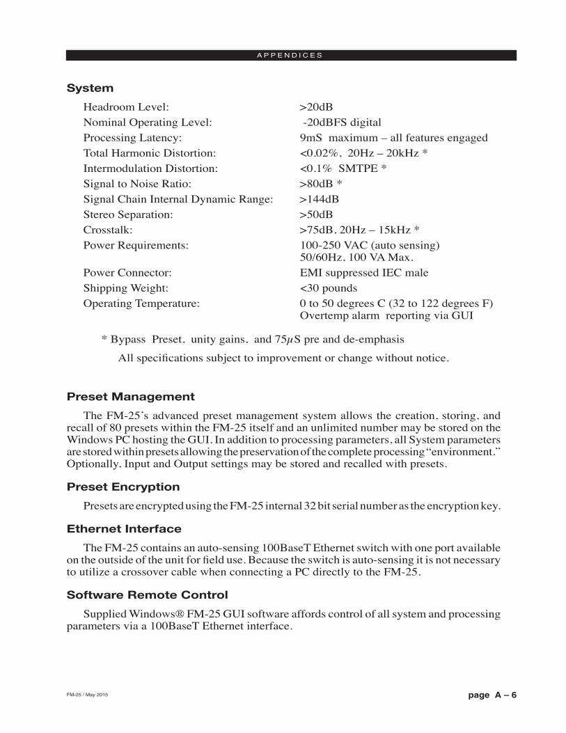
page A – 6FM-25 / May 2015
A P P E N D I C E S
System
Headroom Level: >20dBNominal Operating Level: -20dBFS digitalProcessing Latency: 9mS maximum – all features engaged Total Harmonic Distortion: <0.02%, 20Hz – 20kHz * Intermodulation Distortion: <0.1% SMTPE *Signal to Noise Ratio: >80dB * Signal Chain Internal Dynamic Range: >144dBStereo Separation: >50dBCrosstalk: >75dB, 20Hz – 15kHz *Power Requirements: 100-250 VAC (auto sensing)
50/60Hz, 100 VA Max.Power Connector: EMI suppressed IEC maleShipping Weight: <30 poundsOperating Temperature: 0 to 50 degrees C (32 to 122 degrees F)
Overtemp alarm reporting via GUI
* Bypass Preset, unity gains, and 75µS pre and de-emphasis
All specifications subject to improvement or change without notice.
Preset Management
The FM-25’s advanced preset management system allows the creation, storing, and recall of 80 presets within the FM-25 itself and an unlimited number may be stored on the Windows PC hosting the GUI. In addition to processing parameters, all System parameters are stored within presets allowing the preservation of the complete processing “environment.” Optionally, Input and Output settings may be stored and recalled with presets.
Preset Encryption
Presets are encrypted using the FM-25 internal 32 bit serial number as the encryption key.
Ethernet Interface
The FM-25 contains an auto-sensing 100BaseT Ethernet switch with one port available on the outside of the unit for field use. Because the switch is auto-sensing it is not necessary to utilize a crossover cable when connecting a PC directly to the FM-25.
Software Remote Control
Supplied Windows® FM-25 GUI software affords control of all system and processing parameters via a 100BaseT Ethernet interface.
page A – 7FM-25 / May 2015
A P P E N D I C E S
Appendix B
Interpreting Common Audio Processing Terms .........................A-8Background ................................................................................................................A-8
Audio Terms and Wheatstone Processing .................................................................A-9
Thump/Rumble/Bottom ...........................................................................................A-9
Punch/Boom/Tubby/Warm .....................................................................................A-10
Mud ........................................................................................................................A-10
Honk .......................................................................................................................A-10
Whack ....................................................................................................................A-10
Fuzzy/Tinny ............................................................................................................A-11
Sibilance .................................................................................................................A-11
Treble/Bright/Open .................................................................................................A-11
Finally .....................................................................................................................A-12
Contents
page A – 8FM-25 / May 2015
A P P E N D I C E S
Interpreting Common Audio Processing Terms
BackgroundWhen tasked with adjusting audio processing one is often faced with myriad meanings
for the same sound descriptors. When the program director comments that it needs more “thump,” what does he really mean? If he says that the audio is too “crunchy,” what is he hearing? Or if he says that the competition is nice and “bright” and they have some nice “rumble,” what exactly is that? Or what if he wants more bass and you add some bottom end but now he says “we sound too muddy”? How do we untangle this and get to the bottom of what the PD really means?
Lots of “audio” terms regarding audio processing have been invented and bandied about over the years. Ever since radio stations started employing circuits instead of humans to control the modulation of transmitters we’ve tried to come up with words to describe the effects of processing and what we hear. Many of these terms were born out of simply trying to put into words the positive and negative artifacts of early compressors and limiters (thump, muddy, honk, tubby). Still others were born later when EQ and different forms of “enhancers” were added to audio chains and audio processors to exaggerate certain parts of the frequency spectrum (rumble, punch for bass; bright, airy, open to describe presence and the high end).
The language of audio processing more often than not needs the benefit of an interpreter. Some oft-used terms can easily have multiple meanings and be confused with others. Some of the terms we use simply don’t describe very well what is actually happening to the audio. For instance, one listener might feel the audio is “muddy” while another one still might describe it as “warm.” Which one is right? For starters, “muddy” is not usu-ally used in a positive sense, while warm, on the other hand, often means the sound has a pleasing low end. See the confusion here?
The terms themselves, the ones that we use to describe sound, can be confusing enough. The real question then becomes, what do these terms really mean, and which knob do we turn if we want to change the sound? In fact, here is a very common challenge: if the audio is too “muddy,” do you turn up the high end, or do you reduce the low end? Which control is the right one if you wanted to bring up some low end “rumble” or “sub bass”? And here’s another one; if the audio is “tinny,” is the problem that there’s too much energy up around 8,000Hz or is the problem actually further down in the spectrum?
We’ve created a graphic to try to bring some understanding to the more common terms we broadcasters use to describe sound and where these sounds actually reside in the audio frequency spectrum. While creating an exhaustive list isn’t impossible, it is well beyond the scope of what we’re trying to accomplish here. What we’ve done instead is compile the terms we most commonly hear customers use, and then lay them out in graphic form to help visualize what sounds live in what part of the audio spectrum we hear.
Included in the chart below are the frequency ranges of the most common instruments heard in compilations played on the radio. The idea here is to marry musical instruments and their sounds with the terms we all use. One good example might be the term “Honk,” which coincidentally happens to be right in the middle of the frequency range created by saxophones. The goal here is simple; offer a better understanding of how to adjust an au-dio processor so that the “thump” you want will be the “thump” you get and not “tubby.”
Please note that some of the controls mentioned on the following pages may not be available on the FM-25. The discussion is generic to a wide variety of Wheatstone pro-cessor models.
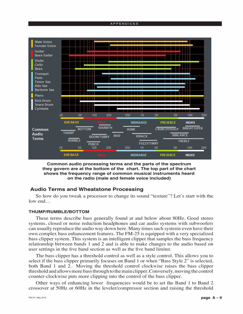
page A – 9FM-25 / May 2015
A P P E N D I C E S
Common audio processing terms and the parts of the spectrum they govern are at the bottom of the chart. The top part of the chart shows the frequency range of common musical instruments heard
on the radio (male and female voice included)
Audio Terms and Wheatstone ProcessingSo how do you tweak a processor to change its sound “texture”? Let’s start with the
low end…
THUMP/RUMBLE/BOTTOM
These terms describe bass generally found at and below about 80Hz. Good stereo systems, closed or noise reduction headphones and car audio systems with subwoofers can usually reproduce the audio way down here. Many times such systems even have their own complex bass enhancement features. The FM-25 is equipped with a very specialized bass clipper system. This system is an intelligent clipper that samples the bass frequency relationship between bands 1 and 2 and is able to make changes to the audio based on user settings in the five band section as well as the five band limiter.
The bass clipper has a threshold control as well as a style control. This allows you to select if the bass clipper primarily focuses on Band 1 or when “Bass Style 2” is selected, both Band 1 and 2. Moving the threshold control clockwise raises the bass clipper threshold and allows more bass through to the main clipper. Conversely, moving the control counter-clockwise puts more clipping into the control of the bass clipper.
Other ways of enhancing lower frequencies would be to set the Band 1 to Band 2 crossover at 50Hz or 60Hz in the leveler/compressor section and raising the threshold
page A – 10FM-25 / May 2015
A P P E N D I C E S
of Band 1. This will allow very low bass to pass more freely through the leveller and compressor section, with the lower bands of the limiter and the bass clipper managing the rest.
PUNCH/BOOM/TUBBY/WARM
The sound of bass “punch” and “boom” usually fall in the range of 70Hz to 150Hz. “Tubby” on the other hand usually falls between 150Hz and 300Hz. Band #2 of the parametric Equalizer may be used to gently and broadly boost audio in the range of 75Hz to 120Hz to safely reinforce the “punch” and “boom” of lower bass without creating undesirable effects such as “tubbiness.”
The enhancement of “punch” and “boom” can be especially tricky because many listeners’ sound systems don’t have the ability to reproduce lower and sub bass frequencies. Therefore it’s especially important to use several known reference systems when adjusting the enhancement of very low frequencies because it is easy to create distortion or “muddiness.” How many stations have awesome sounding bass on the PD’s car stereo but end up sounding terrible on clock radios and boom boxes? Always listen on multiple radios in multiple listening environments to get the best feel for the effects created by purposeful bass enhancement.
MUD
When someone says that audio is “muddy” they usually mean too much energy is in the 250Hz to 400Hz range. Sometimes it’s caused by a misadjusted Equalizer or a processor maladjustment that is allowing a leveller or compressor band to add too much gain. In most cases it’s a good idea to keep from boosting energy in this region. In fact, additional clarity and detail can be created by a broad equalization cut in the range between 180Hz and 400Hz. This surprising little secret can be more effective at “adding” detail in low bass and midrange than adding equalizer boost at the same frequencies. It’s true! Try it!
HONK
Think Saxophone. Honk is above “mud” but below “fuzzy” and “tinny.” Honk oc-curs between about 400Hz and 1,200Hz and begins to overlap “fuzzy” and “tinny” at around 1000Hz. Usually audio in this range stands out on its own in the mix and any enhancement should be slight because our ears are already very sensitive to these fre-quencies. This frequency range is also quite delicate because much of the perceived stereo sound field width also occurs in this range. When audio has a “honk,” “fuzzy,” or “tinny” texture (and it’s usually a texture that one DOESN’T like), faster attack times in the Compressor for that frequency band can help smooth things out. Another trick is to relocate the Band 3 to Band 4 crossover to around 2,000Hz which allows Band 3 to better manage any “harshness” that might tend to pop out on certain material.
WHACK
This is the sound where percussion just “explodes.” First, note that this is much less of an equalization issue and much more about creating a temporarily dense sound by momentary fast compression. To achieve more “whack” it can help to speed up the Leveller or Compressor release times in Band 3. Another trick is to slow down the attack time of the Band 3 leveller which will allow the Band 3 compressor to be more active. This will enhance “whack.”
page A – 11FM-25 / May 2015
A P P E N D I C E S
FUZZY/TINNY
Yes, “fuzzy” and “tinny” really are this far down in the audio spectrum! A “tinny” sound might be described by some as a harsh midrange or too much presence instead of something happening higher up in the audio spectrum. Both “fuzzy” and “tinny” live between about 1,200Hz and 2,000Hz. One of the best ways to manage either is to broadly and slightly reduce equalization in this range, or even increase the attack time in Band 3 of the Leveller and Compressor.
Sometimes there is a tradeoff between getting more “whack” and keeping “fuzzy/tinny” at bay. Speeding up the compressor in the 1,000Hz to 1,500Hz range to get more compression “whack” can sometimes add undesirable side effects, one of which is the creation of what sounds like “fuzzy,” “dense,” or even “tinny.” In audio processing, espe-cially broadcast audio processing, everything is a tradeoff. While Wheatstone processors provide the most wiggle room for getting the sound you hear in your head on the air, sometimes compromises will need to be made.
SIBILANCE
Sibilance is a vocal artifact and because it sounds so unnatural it tends to stick out like a sore thumb. Excessive sibilance can be the result of too much high-end boost or too much final clipper drive. Sibilance tends to be most prevalent in the 4,000Hz to 8,000Hz portion of the frequency spectrum. Microphone processors (like the Wheatstone M1 and M2) are great tools for keeping vocal sibilance under control. Their specialized de-esser sections are specially tailored for removing or minimizing excessive “esses.” When excessive sibilance is an issue and there is no microphone processor to control it, lowering the FM-25’s Band 4 to Band 5 crossover setting and/or using a slightly faster attack time on the Band 5 Leveller/Compressor can help.
Sibilance can sometimes be found in an unlikely place; the L-R. “But voice is mono…” you say, “…so there is no L-R…” Well, yes and no. When the left and right channels don’t have perfect balance or there is phase shift between the channels, energy ends up in the L-R. Why? By definition the L-R signal is the difference between the left and right channels, regardless of whether it’s level, or phase, or both. When phase is the culprit the error is generally larger at high frequencies, making the L-R energy also greater at higher frequencies. As if by magic, sibilance appears in the L-R and the only way to fix it is to tend to what’s causing it or reduce the level of L-R at frequencies where sibilance might reside. The Leveller’s multiband mixer can help with this. Slightly reducing the setting of the Band 4 and Band 5 L-R mixer can help tame sibilance without having too negative an effect on stereo separation.
TREBLE/BRIGHT/OPEN
Treble (like its friends Bass and Midrange) is a generalized term for the high end in most broadcast and recording systems. Bright and Open are oft-used descriptive terms of treble styles.
Unfortunately, bright can be a positive or negative term. For instance, laser-bright is usually a negative term used to describe too much enhancement in the upper end. The term probably borrows its origins from the early days of CDs when brighter supposedly meant cleaner.
Open is a term usually reserved for describing audio texture in the upper midrange when it doesn’t sound overly processed, packed in, or is lacking in detail. To achieve a
page A – 12FM-25 / May 2015
A P P E N D I C E S
more open sound in any processor there is usually some sacrifice in loudness. Fortunately the FM-25 is much more forgiving in this regard and most users have an easier time being loud with the FM-25 while still being quite clean and open. Operating the Leveller and Compressor with slower attack and release times and making some minor tradeoffs in loudness will push perceived quality off the charts while going a long way towards achieving an open and easy to listen to sound. When this is the target sound, starting with one of our Classical or Jazz presets and then “turning things up” is a good way to approach achieving this sound. These presets are surprisingly competitive without sounding “processed.”
FINALLY
As always, Wheatstone’s Tech Support team is available to answer any questions, help with setup, or assist in tweaking your station to the sound you hear in your head but might not know how to achieve. Shoot us an email at [email protected] or give us a call at 252-638-7000. We know our processors inside and out and can make them sit up and dance in any market or format.
page A – 13FM-25 / May 2015
A P P E N D I C E S
Contents
Appendix C
WheatNet-IP Configuration ..........................................................A-14Adding FM-25 to The WheatNet-IP System ..............................................................A-14
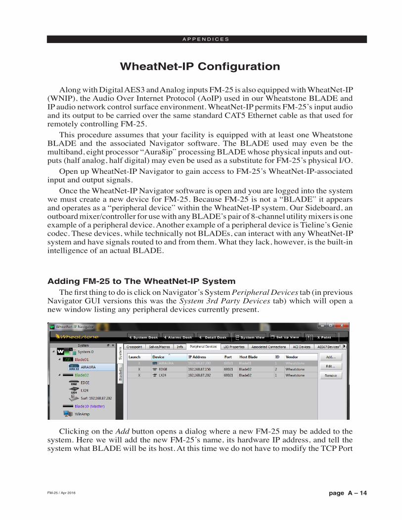
page A – 14FM-25 / May 2015
A P P E N D I C E S
WheatNet-IP Configuration
Along with Digital AES3 and Analog inputs FM‑25 is also equipped with WheatNet‑IP (WNIP), the Audio Over Internet Protocol (AoIP) used in our Wheatstone BLADE and IP audio network control surface environment. WheatNet‑IP permits FM‑25’s input audio and its output to be carried over the same standard CAT5 Ethernet cable as that used for remotely controlling FM‑25.
This procedure assumes that your facility is equipped with at least one Wheatstone BLADE and the associated Navigator software. The BLADE used may even be the multiband, eight processor “Aura8ip” processing BLADE whose physical inputs and out‑puts (half analog, half digital) may even be used as a substitute for FM‑25’s physical I/O.
Open up WheatNet‑IP Navigator to gain access to FM‑25’s WheatNet‑IP‑associated input and output signals.
Once the WheatNet‑IP Navigator software is open and you are logged into the system we must create a new device for FM‑25. Because FM‑25 is not a “BLADE” it appears and operates as a “peripheral device” within the WheatNet‑IP system. Our Sideboard, an outboard mixer/controller for use with any BLADE’s pair of 8‑channel utility mixers is one example of a peripheral device. Another example of a peripheral device is Tieline’s Genie codec. These devices, while technically not BLADEs, can interact with any WheatNet‑IP system and have signals routed to and from them. What they lack, however, is the built‑in intelligence of an actual BLADE.
Adding FM-25 to The WheatNet-IP SystemThe first thing to do is click on Navigator’s System Peripheral Devices tab (in previous
Navigator GUI versions this was the System 3rd Party Devices tab) which will open a new window listing any peripheral devices currently present.
Clicking on the Add button opens a dialog where a new FM‑25 may be added to the system. Here we will add the new FM‑25’s name, its hardware IP address, and tell the system what BLADE will be its host. At this time we do not have to modify the TCP Port
FM-25 / Apr 2016
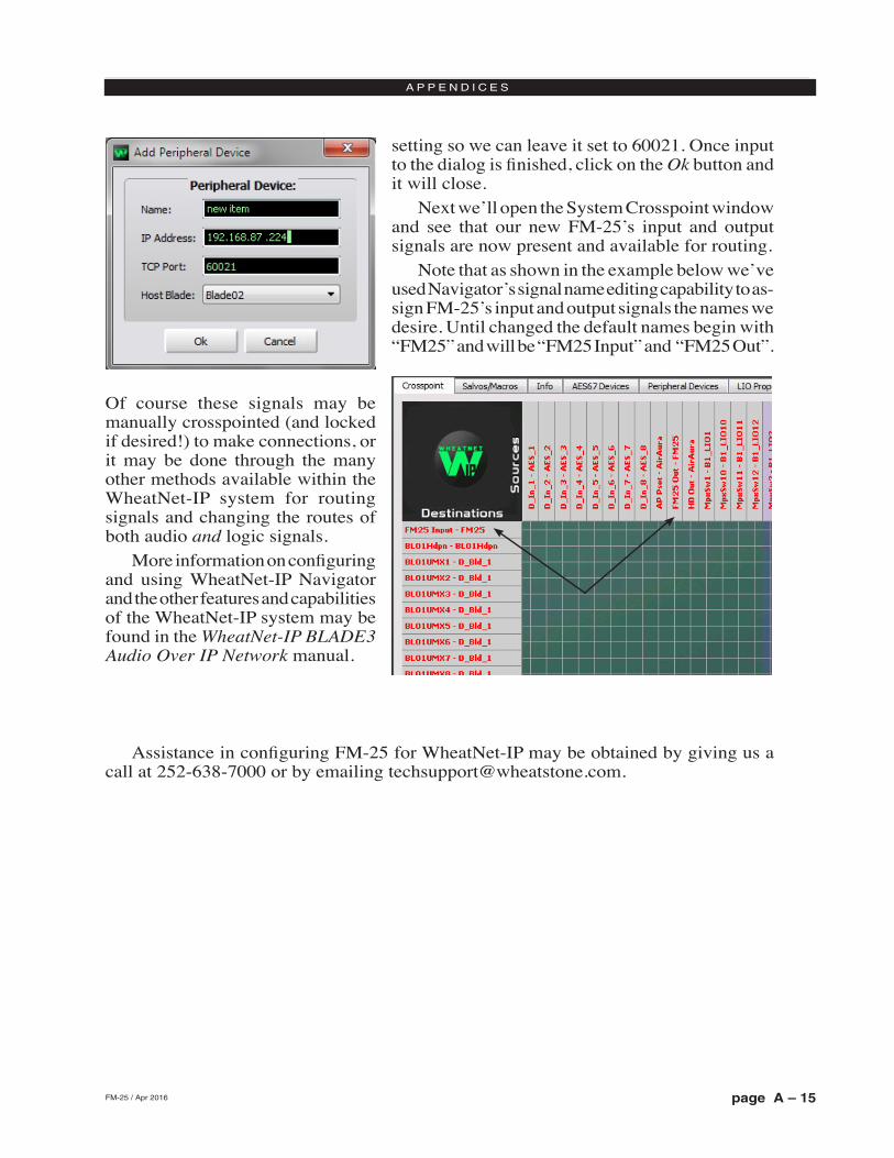
page A – 15FM-25 / May 2015
A P P E N D I C E S
setting so we can leave it set to 60021. Once input to the dialog is finished, click on the Ok button and it will close.
Next we’ll open the System Crosspoint window and see that our new FM‑25’s input and output signals are now present and available for routing.
Note that as shown in the example below we’ve used Navigator’s signal name editing capability to as‑sign FM‑25’s input and output signals the names we desire. Until changed the default names begin with “FM25” and will be “FM25 Input” and “FM25 Out”.
Of course these signals may be manually crosspointed (and locked if desired!) to make connections, or it may be done through the many other methods available within the WheatNet‑IP system for routing signals and changing the routes of both audio and logic signals.
More information on configuring and using WheatNet‑IP Navigator and the other features and capabilities of the WheatNet‑IP system may be found in the WheatNet‑IP BLADE3 Audio Over IP Network manual.
Assistance in configuring FM‑25 for WheatNet‑IP may be obtained by giving us a call at 252‑638‑7000 or by emailing [email protected].
FM-25 / Apr 2016
Top Related