


Languages
Pages
Legal


Fault ride-through enhancement of multi-technology offshore wind farms Arshad Ali Fan Zhang Olimpo Anaya-Lara
EERA Deepwind 2014 23 January 2014, Trondheim, Norway

Background
Problem description
Modelling
FRT control for DFIG
FRT control for DFIG and FRC-WT
Conclusions
Outline of presentation

Scottish Targets - • 80% of power from Renewables by 2020 • Interim target of 31% by 2011 • Currently at 25% (2008 figure) • 20% of primary energy by 2020 • Emission reduction target of 80% by 2050 • Interim target of 42% by 2020
UK Targets –
• 32% of power form renewables by 2020 • Currently at 7% • 15% of primary energy by 2015 • Emission reduction target 80%
by 2050
Government Targets
“Scotland to be a powerhouse of Renewable Energy”
Alex Salmond, First Minister

UK ROUND 3 OFFSHORE WIND SITES - 32GW
Firth of Forth (3.5GW),SSE Renewables and Flour
Moray Firth (1.3GW) Sea Energy Renewables and EDPR
Dogger Bank (9.0GW) – Forewind SSE Renewables, RWE, Statoil, Statkraft
9 Development Zones of varying sizes
Norfolk (7.2GW) – ScottishPower and Vattenfall
Hornsea (4.0GW) – Mainstream and Siemens
Bristol Channel (1.5GW) RWE nPower
Irish Sea (4.2GW) – Centrica
Hastings (0.6GW) - EON UK
Isle of Wight (0.9GW) – Eneco New Energy
£90Bn Capex Investment over the next 10 years 6,800 wind turbines

5
Large-capacity wind farms must remain connected to the network even in the event of faults in the high-voltage network
FRT requirements are different from country to country
»Voltage characteristic for Eire ‘ride through’ requirement
»Voltage characteristic for GB ‘ride through’ requirement
Fault Ride-Through Capability
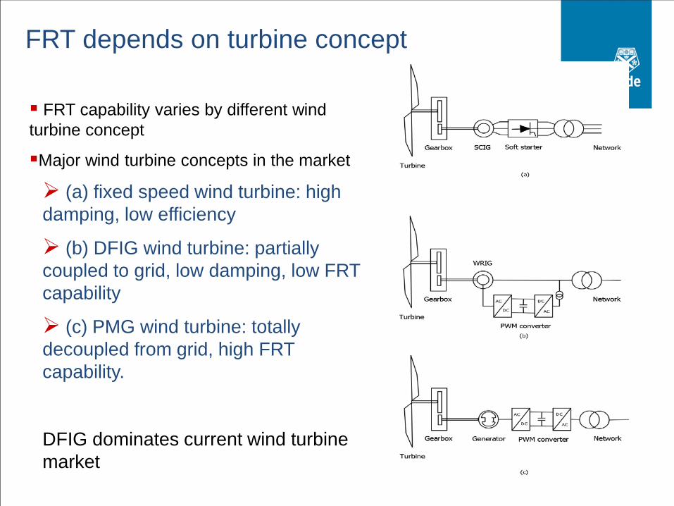
FRT capability varies by different wind turbine concept
Major wind turbine concepts in the market
(a) fixed speed wind turbine: high damping, low efficiency
(b) DFIG wind turbine: partially coupled to grid, low damping, low FRT capability
(c) PMG wind turbine: totally decoupled from grid, high FRT capability.
DFIG dominates current wind turbine market
FRT depends on turbine concept

7
CONTROL SYSTEM Network operator
Gearbox
Crowbar
DFIG
PWM Converters Power Network C1 C2
Wound rotor induction generator
Doubly-fed induction generator (DFIG)

Voltage sags can be typical classified based on the cause, e.g.:
Fault related
Large induction motor start
Large induction motor re-acceleration
DFIG-FRT problem solutions may be:
Modification of conventional controller
Active crowbar control
Application of dynamic breaking resistors
Voltage sags and FRT solutions

Mechanical
Consistent operation, no protection triggered
Loads alleviation
Electrical
High voltage/current protection
Reactive power support
Stable torque generation to avoid wind turbine rotor speed-up
FRT Issues – holistic approach needed
Advantages
Wind turbine stays connected during grid fault
Wind turbine keeps generating power during grid fault
Rotor speed acceleration and drive-train oscillation are prevented
Limitations
Fault level: the power generation is not possible under extremely low grid voltage
High power loss during fault
DFIG control during fault – crowbar with variable resistance

During grid fault, converters are blocked, DFIG operates in SCIG mode. DFIG torque is calculated as:
232
f r r
s
p R IT
sω=
Applying Kirchhoff’s current law to SCIG equivalent circuit, The torque is expressed as
2
22
32
( )
f r s
rs s s r
p R VT
Rs R L L
sω
= + + +
Torque is expressed in terms of rotor resistance
Crowbar with variable resistance

Torque-slip curve of induction machine changes under different rotor resistance and grid voltage
By controlling the rotor resistance, reference torque can be produced under certain grid voltage
Crowbar with variable resistance – T/Slip curve

Switching by grid voltage level
Normal operation: external resistor bypassed
Fault case: IGBT switched to connect variable resistor to DFIG rotor
Implementation

Control implementation – Flow Chart

Test model construction

Wind Turbine Model
Dynamic model of rotor, tower and drive-train DFIG Model
Induction machine model
DFIG controller in d-q frame Grid Model
Generic network model comprising wind farm, conventional power plant with AVR, PSS and etc, Local Grid
Model construction (const)

Electrical torque
Rotor speed
Rotor resistance
Tower acceleration
Solid line: with normal crowbar protection
Dashed line: with variable resistance crowbar control
Simulation results

18
Fully-Rated Converter-based wind turbine
Generator Power
converter Network
Gearbox
Generator Side
Converter
Network Side
Converter
Uses either an induction generator or a synchronous generator (it can either be an electrically excited synchronous generator or a permanent magnet machine. The converter completely decouples the generator from the network, enabling
variable-speed operation. The rating of the power converter in this wind turbine corresponds to the rated power of
the generator.
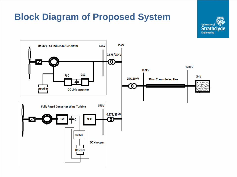
Block Diagram of Proposed System

Results
Without Protection After applying Protection
Vdc_FRC Vdc_FRC 1380V 1120V
Vdc_DFIG 1580V Vdc_DFIG 1220V
Wr_DFIG (pu) Wr_DFIG (pu)

Conclusions
The multi technology wind farm eliminate the need of STATCOM at the point of common coupling (PCC).
Proposed strategy is applied to multi-technology wind farm to eliminate current and voltage transients during grid faults.
The DC link voltage and high rotor currents are controlled within limits after applying the protection scheme.

Top Related