


Languages
Pages
Legal


Vers. 001 Energy 8012 GAS 1
GB
USE AND MAINTENANCE MANUAL AND
INSTRUCTIONS FOR INSTALLATION
GB
ENERGY 8012 GAS
V. 001 - May 2008
GENERATORS

Energy 8012 G Vers. 001
GB
2
INDEX 1 FOREWORD ................................................................................................................................... 5
1.1 Purpose and scope of this manual ............................................................................................ 5 1.2 Symbols and Definitions ............................................................................................................ 5 1.3 General Information .................................................................................................................. 5
2 GENERATING SET IDENTIFICATION DATA ............ ..................................................................... 6
2.1 Components (Fig. 1) ................................................................................................................. 6 2.2 Identification plate (Fig. 2) ......................................................................................................... 6 2.3 Dimensions ............................................................................................................................... 6 2.4 Fiche technique......................................................................................................................... 7
3 SHIPPING, HANDLING, STORAGE ................... ............................................................................ 7
3.1 Storage ..................................................................................................................................... 7 3.2 Weight ...................................................................................................................................... 8 3.3 Handling ................................................................................................................................... 8
4 INSTALLATION .................................. ............................................................................................ 8
4.1 PRELIMINARY NFORMATION ................................................................................................. 8 4.2 FASTENING the generating set ................................................................................................ 8 4.3 FASTENING the pressure reducer ............................................................................................ 9 4.4 Preparing the Wiring connection ............................................................................................. 10 4.5 Battery connection .................................................................................................................. 10 4.6 12 Volt connection .................................................................................................................. 10 4.7 Connection of Auxiliary cables ................................................................................................ 11 4.8 Electronic control panel connection ......................................................................................... 11 4.9 Additional muffler connection .................................................................................................. 12
5 OPERATING INSTRUCTIONS ...................................................................................................... 14
5.1 Machine safety ........................................................................................................................ 14 6 USING THE GENERATING SET ................................................................................................... 14
6.1 Control panel description ........................................................................................................ 14 6.2 MANUAL operation ................................................................................................................. 15 6.3 AUTOMATIC operation ........................................................................................................... 15 6.4 Control and Alarm Functions ................................................................................................... 15 6.5 Notice ..................................................................................................................................... 16 6.6 Turning the generating set off ................................................................................................. 16 6.7 Information on forbidden use................................................................................................... 17 6.8 Useful tips ............................................................................................................................... 17
7 MAINTENANCE INSTRUCTIONS ...................... ........................................................................... 17
7.1 Maintenance schedule ............................................................................................................ 17 7.2 Maintenance not requiring skilled personnel ........................................................................... 17 7.3 Checking the engine oil level................................................................................................... 18 7.4 Maintenance operations calling for qualified personnel ........................................................... 18
7.4.1 Engine oil replacement ..................................................................................................... 18 7.4.2 Air filter maintenance ....................................................................................................... 19 7.4.3 Spark plug maintenance................................................................................................... 19 7.4.4 Voltage adjustment .......................................................................................................... 20
8 DISMANTLING ................................... ........................................................................................... 20 9 FIRE-PREVENTION ...................................................................................................................... 20

Vers. 001 Energy 8012 G
GB
3
GENERAL WARRANTY TERMS ............................ ........................................................................... 21 WIRING DIAGRAM ENERGY 8012 GAS .................... ....................................................................... 22 DRAWING FOR SPARE PARTS LIST ENERGY 8012 GAS ...... ....................................................... 24
Energy 8012 G Vers. 001
GB
4
Via E. Majorana , 49 48022 Lugo (RA) ITALY
"CE" COMPLIANCE STATEMENT
Under Machine Directive 89/392/EEC, attachment II A We hereby represent that the generator-set, the data concerning which appear below, has been designed and built to correspond to the essential safety and health requirements laid down by the European Directive on Machine Safety. This statement shall not be valid any longer if any changes are made on the machine without our written ap-proval. Machine: GENERATOR-SET Model: ENERGY 8012 GAS Serial number: ………………………... Directive of reference: Machine Directive (89/392/EEC) in version 91/31/EEC Low Voltage Directive (73/23/EEC) Electro-magnetic Compatibility (89/336/EEC) in version 93/31/EEC Harmonised standards applied, especially: EN 292-1; EN 292-2; EN 60204-1 DATE ........ 29/04/2008.......... THE PRESIDENT
Vers. 001 Energy 8012 G
GB
5
1 FOREWORD
Refer carefully to this man-ual before performing any operation on the air conditioner. 1.1 Purpose and scope of this manual This manual has been drawn up by the Manufac-turer in order to provide basic information and in-structions for performing every operation for ser-vicing and using the generating set in a proper and safe manner. It is an integral part of the equipment of the gen-erating set, must be kept with care throughout the life of the same, and must be protected against any agent which could damage it. It must follow the generating set if the latter is in-stalled on a new vehicle, or if its ownership changes hands. The information in this manual is addressed to the personnel which must install the generating set, and to all those involved in its maintenance and use. This manual sets out the purpose the machine was designed for, and contains all the information required to guarantee that it is used in a safe and proper fashion. Constant attention to the instructions laid down here will guarantee the safety of the user, econ-omy and longer life of the machine. To facilitate reference, this manual has been subdivided into chapters which specify the main notions; for quick consultation, refer to the table of contents. The most important parts of the text are in bold letters and preceded by symbols described be-low. It is strongly recommended that you read the con-tents of this manual and the reference documents carefully; doing so is essential to the correct long-term performance and reliability of the generator set and the prevention of injury and/or damage. Note: The information contained in this publica-tion was correct at the time it went to print, but may be modified without advance notice.
1.2 Symbols and Definitions "Graphic safety symbols” have been employed in this booklet to identify different levels of danger or important information.
This means that you must pay attention to avoid serious consequences which might lead to serious accidents or damage the health of the operators.
This means a potentially hazardous situation which could lead to accidents or to damage to property.
This calls the user’s attention to a potentially dangerous situation which could cause malfunction or damage to the machine. The drawings are only provided by way of exam-ple. Even though the machine you actually have may differ from the illustrations contained in this man-ual, safety and information about the same are guaranteed. The manufacturer, as part of his policy of con-stant product development and updating, may ef-fect changes without providing advance notice. 1.3 General Information The ENERGY 8012 GAS generating set has been designed for installation on vehicles. It can supply power at a voltage of 13.5 Vdc. The ENERGY 8012 GAS model must be fed with LPG. In order to achieve a low noise level, the EN-ERGY series generating sets are provided with internally insulated sound-proofing boxes. They can be accessed easily in order to perform maintenance work, and are provided with a re-mote control panel which can be installed inside the vehicle.
Energy 8012 G Vers. 001
GB
6
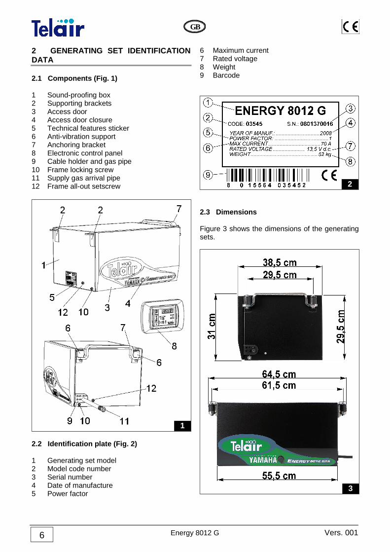
2 GENERATING SET IDENTIFICATION DATA 2.1 Components (Fig. 1) 1 Sound-proofing box 2 Supporting brackets 3 Access door 4 Access door closure 5 Technical features sticker 6 Anti-vibration support 7 Anchoring bracket 8 Electronic control panel 9 Cable holder and gas pipe 10 Frame locking screw 11 Supply gas arrival pipe 12 Frame all-out setscrew
2.2 Identification plate (Fig. 2) 1 Generating set model 2 Model code number 3 Serial number 4 Date of manufacture 5 Power factor
6 Maximum current 7 Rated voltage 8 Weight 9 Barcode
2.3 Dimensions Figure 3 shows the dimensions of the generating sets.
3
2
1

Vers. 001 Energy 8012 GAS 7
GB
2.4 Fiche technique ENERGY ENGINE 8012 GAS
Type Single-cylinder, 4-stroke LPG, overhead-valve, air cooled
Engine Yamaha MZ 175 GAS
Displacement cm3 171
Bore x Stroke mm 66 x 50
Max Fuel Consumption 1.2 l/h
Fuel supply LPG or Propane pure when it is cold
Ignition system Electronic
Spark plug BPR4ES
Oil sump capacity litres 0.6
Speed governor Automatic, centrifugal mass type
ALTERNATOR 8012 GAS
Type Salient-pole rotor – Stator with brushes and built-in
rectifier – Separate voltage regulator Max power Watt 945
Steady power Watt 945
Voltage Volt 13.5
Direct current output Ampere 70
Rotor insulation class H
Stator insulation class F
Cooling Centrifugal fan
GENERATOR 8012 GAS
Overall weight kg 52
Overall dimensions (Length x Width x Height)
mm 555 x 385 x 295
Starting Electric / Manual - Automatic
Supply device Pressure reducer Noise level 82 (56 dBA 7 m) Running hours h 7 3 SHIPPING, HANDLING, STORAGE 3.1 Storage The generating set is protected during shipping by suitable carton packaging and a wooden base. It must be stored horizontally, in a covered, dry and ventilated area.
When using the genera-tor in cold environments, please remem-ber that the lower the temperature (down to a temperature limit of – 15°C), the high-er the percentage of propane gas which is recommended
Energy 8012 G Vers. 001
GB
8
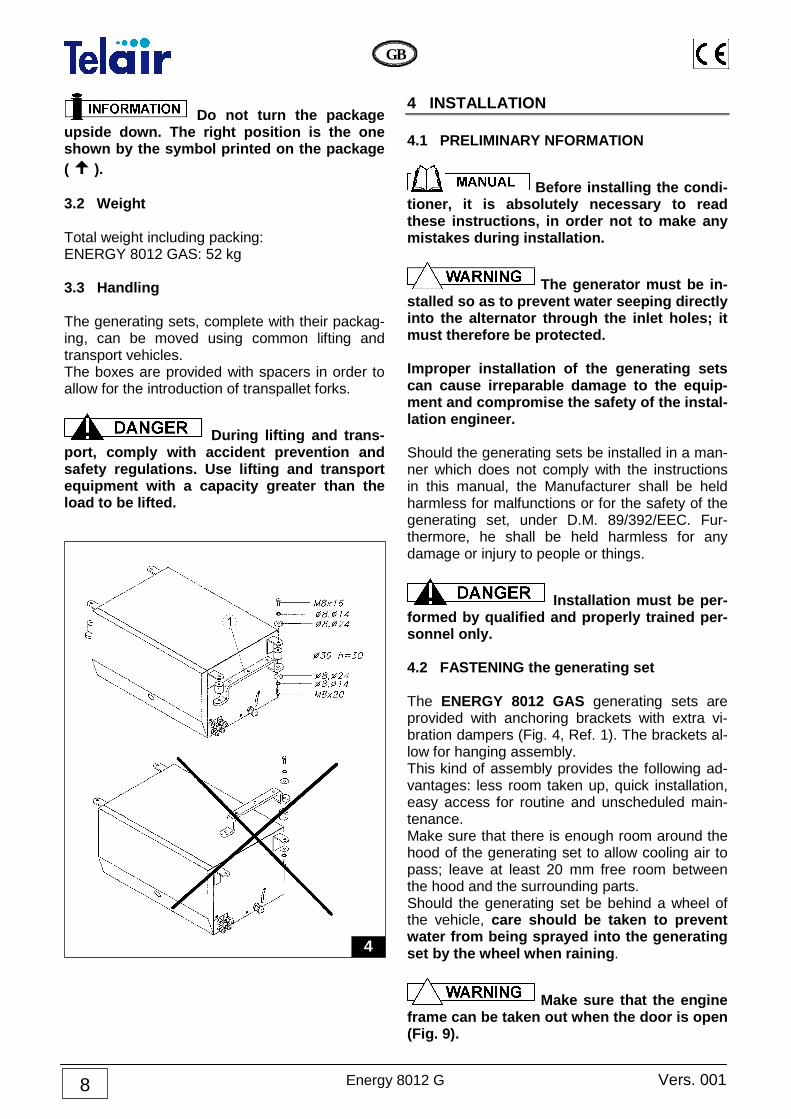
Do not turn the package upside down. The right position is the one shown by the symbol printed on the package ( � ). 3.2 Weight Total weight including packing: ENERGY 8012 GAS: 52 kg 3.3 Handling The generating sets, complete with their packag-ing, can be moved using common lifting and transport vehicles. The boxes are provided with spacers in order to allow for the introduction of transpallet forks.
During lifting and trans-port, comply with accident prevention and safety regulations. Use lifting and transport equipment with a capacity greater than the load to be lifted.
4 INSTALLATION 4.1 PRELIMINARY NFORMATION
Before installing the condi-tioner, it is absolutely necessary to read these instructions, in order not to make any mistakes during installation.
The generator must be in-stalled so as to prevent water seeping directly into the alternator through the inlet holes; it must therefore be protected. Improper installation of the generating sets can cause irreparable damage to the equip-ment and compromise the safety of the instal-lation engineer. Should the generating sets be installed in a man-ner which does not comply with the instructions in this manual, the Manufacturer shall be held harmless for malfunctions or for the safety of the generating set, under D.M. 89/392/EEC. Fur-thermore, he shall be held harmless for any damage or injury to people or things.
Installation must be per-formed by qualified and properly trained per-sonnel only. 4.2 FASTENING the generating set The ENERGY 8012 GAS generating sets are provided with anchoring brackets with extra vi-bration dampers (Fig. 4, Ref. 1). The brackets al-low for hanging assembly. This kind of assembly provides the following ad-vantages: less room taken up, quick installation, easy access for routine and unscheduled main-tenance. Make sure that there is enough room around the hood of the generating set to allow cooling air to pass; leave at least 20 mm free room between the hood and the surrounding parts. Should the generating set be behind a wheel of the vehicle, care should be taken to prevent water from being sprayed into the generating set by the wheel when raining .
Make sure that the engine frame can be taken out when the door is open (Fig. 9).
4
Vers. 001 Energy 8012 G
GB
9
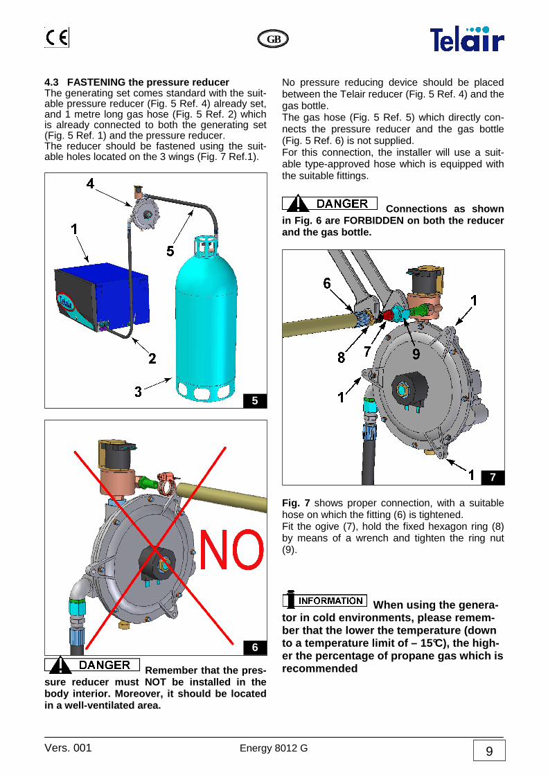
4.3 FASTENING the pressure reducer The generating set comes standard with the suit-able pressure reducer (Fig. 5 Ref. 4) already set, and 1 metre long gas hose (Fig. 5 Ref. 2) which is already connected to both the generating set (Fig. 5 Ref. 1) and the pressure reducer. The reducer should be fastened using the suit-able holes located on the 3 wings (Fig. 7 Ref.1).
Remember that the pres-sure reducer must NOT be installed in the body interior. Moreover, it should be located in a well-ventilated area.
No pressure reducing device should be placed between the Telair reducer (Fig. 5 Ref. 4) and the gas bottle. The gas hose (Fig. 5 Ref. 5) which directly con-nects the pressure reducer and the gas bottle (Fig. 5 Ref. 6) is not supplied. For this connection, the installer will use a suit-able type-approved hose which is equipped with the suitable fittings.
Connections as shown in Fig. 6 are FORBIDDEN on both the reducer and the gas bottle.
Fig. 7 shows proper connection, with a suitable hose on which the fitting (6) is tightened. Fit the ogive (7), hold the fixed hexagon ring (8) by means of a wrench and tighten the ring nut (9).
When using the genera-tor in cold environments, please remem-ber that the lower the temperature (down to a temperature limit of – 15°C), the high-er the percentage of propane gas which is recommended
7
6
5

Energy 8012 G Vers. 001
GB
10
4.4 Preparing the Wiring connection
Use the suitable key to open the lock and remove the front door. Then remove the fastening screw (Fig. 8 Ref. 2) of the lower surface on both sides.
Take out the lower surface with the engine up to the retainer (Fig. 8 Ref. 3) Should you wish to take out the engine holding surface in full, remove the setscrews (Fig. 8 Ref. 3) too.
The wiring connections to the generating set must be made by quali-fied personnel. 4.5 Battery connection To start up the generating set, you must connect to the vehicle battery using a sheathed cable (to determine its cross-section, see Table 1) in com-pliance with the regulations in force. For this purpose, the generating set is provided with two terminals (Fig. 10 Ref. 1) used to con-nect the positive and the negative poles of the battery.
Connect the positive pole cable (red cable) to the terminal which is already provided with a red ca-ble, and the cable of the negative pole to the terminal already provided with a black cable. The cable of the negative pole must be of the same cross-section as the positive cable and must be connected to both the negative pole of the bat-tery and the chassis of the vehicle. The contact must be good. If necessary, remove any paint or rust from the contact surface, and protect the connection with grease. The start-up battery must have a capacity of at least 100 A/h . The soundproofing case is provided with a cable holder to let the battery connection cables go through (Fig. 8 Ref. 1). The cable holder will prevent water from entering the generating set.
Check the proper posi-tion of the 12 Vdc current pick-up line care-fully. A wrong connection could cause irrepa-rable damage to the generating set or create dangerous short circuits . 4.6 12 Volt connection Any use of 12 Vdc is to be drawn from the gen-erating set battery, via a cable of suitable size. The cable of the negative pole must be of the same cross-section as the positive cable.
Even if the generating set is provided with a power cutout fuse (Fig. 10 Ref. 5) in case of overload or short-circuit, a suitably calibrated thermal cutout should be installed inside the switchboard of the vehi-cle, which disconnects the power line to us-ers whenever power input exceeds 70 Amp.
TABLE 1
Battery Connection
Cable length < 6 m > 6 m
Cross sect. mm 2 25 35
9
8

Vers. 001 Energy 8012 G
GB
11
4.7 Connection of Auxiliary cables 2 auxiliary cables are to be connected, both are provided with a polarized connector. • A 5 m long cable is delivered standard for
connection from the generating set to the control panel. Make sure it is long enough for the selected path from the generating set to the control panel. Longer cables are available as an option. See also paragraph 4.8. Let the cable through the cable holder (Fig. 8 Ref. 1) and connect the white connector (ob-serve proper fitting side) to the fixed connec-tor (fig. 10 Ref. 3) which is located inside the generating set over the fuses.
• A cable is delivered standard together with the generating set for connection from the generating set to the pressure reducer. It is already connected to the pressure reducer. Let the cable through the cable holder (Fig. 8 Ref. 1) and connect the 3-pole white connec-tor to the fixed connector (Fig. 10 Ref. 2) which is located inside the generating set near the 12 Vdc terminals.
4.8 Electronic control panel connection Choose the position you want inside the vehicle and make a rectangular hole sized 30 x 32 mm. Let the connection cable coming from the gener-ating set out of the hole (paragraph 4.7) and connect the black connector of the cable on the back of the electronic control panel. Fasten the electronic control panel (Fig. 11) using self-tapping screws sized 3 x 20 mm, and make sure that the rear part does not touch other surfaces; use slight pressure to fasten the plastic frame un-til you hear the click of the fastening tabs.
10
11

Energy 8012 G Vers. 001
GB
12
4.9 Additional muffler connection To further reduce the noise level released by the generating set, an additional (optional) muffler can be installed on the outside. The additional muffler kit is coded 02482 and consists of the following: • A muffler coded 02019 (Fig. 12 Ref. 1). • A steel flexible hose, 1 m long, coded 00433
(Fig. 12 Ref. 2). • Two fastening clamps coded 00543 (Fig. 12
Ref. 3). • A pipe fitting for flexible hoses coded 03645
(Fig. 12 Ref. 4).
To connect the muffler to the generating set, re-move first the door (Fig. 13 Ref. 2) by means of the suitable wrench (Fig. 13 Ref. 1) and then the muffler casing (Fig. 13 Ref. 3)
Remove all parts of the flame trap (Fig. 14 Ref. 2 – 3 – 4 – 5) from the muffler (Fig. 14 Ref. 1). After inserting the fitting coded 03645 (Fig. 15
13
14
12
15
Vers. 001 Energy 8012 G
GB
13
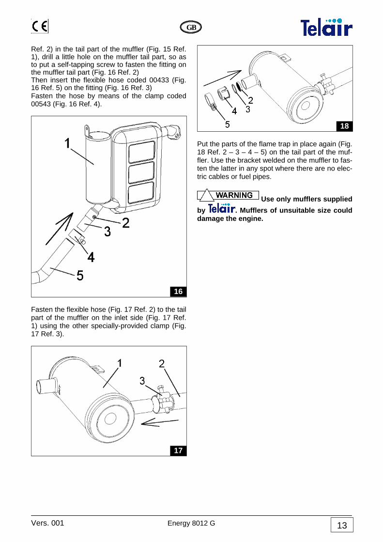
Ref. 2) in the tail part of the muffler (Fig. 15 Ref. 1), drill a little hole on the muffler tail part, so as to put a self-tapping screw to fasten the fitting on the muffler tail part (Fig. 16 Ref. 2) Then insert the flexible hose coded 00433 (Fig. 16 Ref. 5) on the fitting (Fig. 16 Ref. 3) Fasten the hose by means of the clamp coded 00543 (Fig. 16 Ref. 4).
Fasten the flexible hose (Fig. 17 Ref. 2) to the tail part of the muffler on the inlet side (Fig. 17 Ref. 1) using the other specially-provided clamp (Fig. 17 Ref. 3).
Put the parts of the flame trap in place again (Fig. 18 Ref. 2 – 3 – 4 – 5) on the tail part of the muf-fler. Use the bracket welded on the muffler to fas-ten the latter in any spot where there are no elec-tric cables or fuel pipes.
Use only mufflers supplied
by . Mufflers of unsuitable size could damage the engine.
18
17
16

Energy 8012 G Vers. 001
GB
14
5 OPERATING INSTRUCTIONS
The generating set is de-livered without engine oil. Use detergent oil for multigrade 4-stroke petrol engines, having SAE viscosity suitable for the operating climate (see ta-ble and detailed indications on the user and maintenance manual of the engine) . The Energy 8012-G generating set consists of an endothermic engine connected to an alternator able to produce direct electric current. It is as-sembled inside a steel plate casing, insulated and sound-proofed using special sound absorb-ing materials. The gas is fed to the endothermic engine by a pressure reducer which is pre-calibrated and as-sembled standard on the generating set. This generating set can work up to an altitude of 1000 m above sea level. 5.1 Machine safety The generating sets come with perfectly sealed casings, so there is no danger of contact with any mobile parts, with high temperatures or with live cables. The doors open with a lock and key. The keys must not be left within the reach of children or in-expert people.
The generating sets must be used only and exclusively with their doors shut. Remove any flammable substance from near the generating set, for example: petrol, paints, solvents, etc. The hot parts of the generating sets must never be in touch with easily flammable mate-rials. Never touch the generating sets or the wiring connections with wet hands. Never replace the fuses or the thermal switches using others having a higher am-perage. Should you have to check any electrical part, this must be done only with the engine turned off and by skilled personnel. I gruppi elettrogeni sono stati realizzati in accor-do alle norme di sicurezza indicate nella dichia-razione di conformità CEE. 6 USING THE GENERATING SET 6.1 Control panel description The Energy 8012 generating sets are provided with an automatic electronic remote control panel which allows you to perform starting up / turning off and automatic / manual operations as well as to check their running conditions.

Vers. 001 Energy 8012 G
GB
15
The elements making them up are: 1 ON/OFF switch for the start-up and switch-off
function 2 AUTO/MAN switch for the automatic or man-
ual function 3 Display 4 Hour or voltmetric switch button 5 Reset 6 Generator running indicator (flashing) 7 Automatic function indicator 8 Startup failed indicator 9 Maintenance request indicator 10 Fuel reserve indicator 11 Battery charged indicator 12 Minimum oil level indicator 13 High temperature indicator 6.2 MANUAL operation Position the AUTO/MAN (2) switch on the MAN position and set the startup switch (1) to ON posi-tion. The word WAIT will appear on the display (3) for 8 seconds. When these have run out, the electronic control panel will start the first auto-matic procedure for starting up the generating set. If the engine starts up at the end of this phase, then the generator running indicator (6) will start to flash. Should the engine not start up, this automatic procedure will be repeated up to 4 times. If the engine has not started up yet at the end of this complete cycle, the startup failed indicator (8) will light up. If only the startup failed indicator (8) stays lit, you can repeat the startup procedure several times. If the generating set has not started up at all even after many attempts, you will have to get in touch with the after-sales service. During the operation in manual mode, the display (3) will show the total running hours of the gener-ating set. Press the hour or voltmetric switch button to dis-play the running hours after the last mainte-nance. 6.3 AUTOMATIC operation Position the AUTO/MAN (2) switch on the AUTO position and set the startup switch (1) to ON posi-tion. The automatic function indicator (7) will light up. If the battery which supplies the generating set has a voltage of more than 11.5 Volts, the battery charged indicator (11) will light up. When the voltage at the ends of the 12Vdc ter-minals of the generating set is lower than 11.5
Volts, the battery charged light indicator (11) will go off and the generating set will begin the startup procedure (similar to that of the manual operation). During the operation in automatic mode, the dis-play (3) will show the total running hours of the generating set. Press the hour or voltmetric switch button to display the voltage at the ends of the 12Vdc terminals, or at the ends of the battery. When the battery is charged, the battery charged indicator (11) will light up and the electronic con-trol panel will turn off the generating set. 6.4 Control and Alarm Functions 3 DISPLAY: when the generating set has started up, the total running hours will be displayed. Press the hour or voltmetric switch button during the manual operation to display the running hours after the last maintenance. Press the hour or voltmetric switch button during the automatic operation to display the voltage at the ends of the 12Vdc terminals, or at the ends of the battery. 4 HOUR and VOLTMETRIC SWITCH BUTTON: when in MAN (2) function, press this button to display the running hours elapsed after the last change of the engine oil. When in AUTO (2) func-tion, press this button to display the voltage at the ends of the 12Vdc terminals. 5 RESET: when the display shows any charac-ters without logic, the panel is to be reinitialised. Press the Reset key and, holding it down, switch on the panel. When 4 zeroes (0000) are shown on the display, the panel is reinitialised. 6 GENERATOR RUNNING INDICATOR: this in-dicator flashes during proper operation of the generating set. 7 AUTOMATIC FUNCTION INDICATOR: this pi-lot lamp is illuminated as long as the AUTO (2) function is selected. 8 STARTUP FAILED INDICATOR: this pilot lamp will light up to indicate that the generating set has not started up, after all four attempts at starting up have failed. 9 MAINTENANCE REQUEST INDICATOR: this pilot lamp flashes after 50 running hours have elapsed and the engine oil level is to be checked. When the lamp illuminates steady, this means that 100 running hours have elapsed and the en-gine oil is to be changed. Upon every engine oil

Energy 8012 G Vers. 001
GB
16
change the After-sales service must reset the Timer to make it restart from zero. To reset the flashing light, press the switch button (4) and, holding it down, switch on the electronic panel by means of the switch (1). 10 GAS RESERVE INDICATOR: if a reserve de-tector is provided in the gas tank, it is possible to connect the suitable cable located inside the generating set (Fig. 10 Ref. 4). This way the pilot lamp will light up when the gas level has gone below its reserve level. 11 BATTERY CHARGED INDICATOR: this pilot light is illuminated as long as the voltage at the ends of the 12Vdc terminals, located inside the generating set, is more than 11.5 Volts.
12 MINIMUM ENGINE OIL LEVEL INDICATOR: this pilot lamp will light up to indicate that the level of oil in the engine has gone below the minimum level. A safety system turns off the en-gine automatically in order to avoid damages. 13 HIGH TEMPERATURE INDICATOR: this pilot lamp will light up when the temperature of the generating set goes over its safety value; the en-gine will stop at the same time. 6.5 Notice The warning light located inside the generating set (Fig. 10 Ref. 7) lights up only during the startup phase and serves to give the alternator the startup excitation. Remember that the battery connected to the 12Vdc terminals of the generating set performs two functions: starting up the engine and storing the energy supplied by the generating set; it must therefore have a minimum value of 100 Ampere . The Energy 8012 generating set, when in auto-matic mode, will turn on not only when the bat-tery is down, but also when you connect a load such as to make the battery voltage drop below 11.5 Volts .
Applying any load higher than the energy just then available in the bat-tery will prevent the generating set from turn-ing on due to insufficient voltage .
If you do not use the vehi-cle for long periods, we recommend you to
start up the generating set periodically to en-sure a properly charged battery . Remember that the time which is taken by the generating set in automatic mode to recharge the battery may vary according to the battery status, the amount of connected batteries and the sea-son temperature. Generally, the lower the temperature the less the time required to charge the battery. 6.6 Turning the generating set off To stop the generating set, place the switch (1) in its "OFF" position.
The generating set is provided with an internal combustion engine; therefore the fuel used is highly flammable. The exhaust gases are conveyed under the hood; their temperature, inevitably, is quite high, even though they are mixed with cool-ing air. Do not touch the hood areas near the ex-haust, and do not put your hands or other ob-jects inside the hood.
When using the genera-tor in cold environments, please remem-ber that the lower the temperature (down to a temperature limit of – 15°C), the high-er the percentage of propane gas which is recommended

Vers. 001 Energy 8012 G
GB
17
6.7 Information on forbidden use
The generating set must be installed and used only by personnel qualified and authorised according to the manufacturer’s instructions. The generating set must be used only and exclusively to pro-duce electrical power on vehicles provided with an electrical system made according to standards and depending on the quantity of power delivered. 6.8 Useful tips During the running-in period, do not subject the new engine to a load higher than 70% of the rated load, at least for the first 50 running hours. 7 MAINTENANCE INSTRUCTIONS
Use only original spare parts. The use of spare parts of non-equivalent quality may damage the generat-ing set. Periodical control and adjustments are of the essence in preserving a high level of performance. Routine maintenance also ensures long generating set life.
Before performing any check or maintenance operation on the gen-erating set, turn the ON/OFF switch of the control panel to the OFF position and the AUTO/MAN switch of the control panel to the MAN position.
Then disconnect the red 12 Vdc cable from the terminal (Fig. 10 Ref. 1) This way you can operate under safe condi-tions as the generating set cannot start up. 7.1 Maintenance schedule See the table at the bottom of the page. 7.2 Maintenance not requiring skilled per-sonnel To perform this kind of check, it will be necessary to open the door of the generating set. The fol-lowing precautions must therefore be taken: 1 The generating set must not be running, and
all its parts must be cold. 1 Let the generating set cool off.
ROUTINE MAINTENANCE SCHEDULE To be performed after the period of time or the number of running hours listed here, whichever the earlier may be.
Every use Every
month or 20 h
Every 6 month or
100 h
Every ye-ar or 300
h
Engine oil Inspection ● Change ● (2) ● (2)
Air filter Cleaning (1) ● (2) Spark plug Inspection-cleaning ● (2) Valve adjustment Check-adjust ● (2) Tank and fuel filter. Cleaning ● (2)
Engine r.p.m.’s or frequency Adjust ● (2)
Vibration damper suspension points Check ● (2)
Fuel pipes Check (replace if necessary) Every two years
NOTES: (1) Clean more frequently if you use it in a very dusty environment. (2) These operations must be performed by specialised personnel only

Energy 8012 G Vers. 001
GB
18
7.3 Checking the engine oil level Unscrew the engine oil level reference cap and clean the dipstick (Fig. 19 ref. 1). • Put the dipstick back in without screwing. • Take the dipstick out again, and make sure
that the engine oil level is between the two notches (min and max). Should the oil level be below the minimum notch, restore the level of the oil with the kind of motor oil advised (refer to the engine user and maintenance manual).
• Put the dipstick cap back on and screw tightly.
Do not exceed the maxi-mum level, since this could cause malfunc-tion of the generating set.
Every engine oil level checking operation must be performed with the generating set in a perfectly horizontal position. 7.4 Maintenance operations calling for qualified personnel With certain maintenance operations, it is possi-ble to take out the engine-alternator unit, remov-ing the locking screw (Fig. 8 Ref. 2) of the lower surface on both sides. This will make it easier to access all the inside parts of the generating set for unscheduled main-tenance or repair operations. 7.4.1 Engine oil replacement Use multigrade detergent oil for four-stroke petrol engines having a SAE viscosity suited to the cli-mate the generating set is working in (see table and detailed instructions shown on the engine use and maintenance manual).
To make it easier to take the engine oil out, it is best to heat the engine for 3 - 5 minutes; this way, the oil will be more fluid and emptying will be quicker and more complete.
Loosen the special cap on the oil pan(Fig. 20 ref. 1) by a few turns, and let all the oil inside run out into a collection container (Fig. 21 ref. 2).
When this has been done, screw the cap back on again and restore the oil level inside the engine pan, using the filler hole (Fig. 19 Ref. 2).
21
20
19
For cold climates
For hot climates

Vers. 001 Energy 8012 G
GB
19
For the quantity of oil to be fed into the pan, see the following table (Table 2).
MOD. Quantity of oil (litres)
Energy 8012 GAS 0,6 Tab. 2
• Hot oil can scald. • Running the engine when the oil level is
too low can damage it seriously • Check the oil level when the engine has
been turned off .
Used oil must not be dis-posed of in the open, but handed over to companies specialising in disposal and/or re-cycling according to the laws current in the country where such operations are per-formed.
7.4.2 Air filter maintenance
A dirty air filter will reduce the air flow to the carburettor. To prevent carburettor malfunction, check the air filter regularly. If the engine is used in an espe-cially dusty environment, we suggest you check it every time before starting up.
Never use Diesel fuel or solvents with a low evaporation point for cleaning the air filter cartridge.
Never run the engine without the air filter; the engine would wear down quickly due to dust in the air. To access the filter cartridge, remove the air filter closing lid (Fig. 24 ref. 3) after having unscrewed
both screws which keep it attached to the air filter box. Take out the cartridge (Fig. 26 ref. 1) and wash it using a neutral detergent solution and rinse care-fully. Let the filter cartridge dry out completely, then dip it in clean motor oil. Squeeze out care-fully in order to remove excess oil. Replace the cartridge only if it should be visibly no longer whole. 7.4.3 Spark plug maintenance For both models of generating sets, use spark plugs mod. BP6ES, BPR6ES (NGK), W20EP-U, W20EPR-U (ND) or else spark plugs made by other manufacturers but compatible with the above. Never use spark plugs with a different tempera-ture degree from those listed above. • Take the cap off the spark plug (Fig. 26 Ref.
2) and using the special wrench take out the plug.
• Perform a sight check. Replace in case of ob-
vious war or if the insulator is broken or cracked.
• Use a steel brush to clean the spark plug, if it can be used again.
• Use a thickness gauge to measure the dis-
tance between the electrodes. The right dis-tance should be between 0.7 and 0.8 mm (Fig. 23).
• Correct the distance if necessary, folding the side electrode.
• Make sure that the spark plug washer is in good condition and then screw back on by
23
22
Energy 8012 G Vers. 001
GB
20
hand so as to be sure it is put back in place properly. Finally, tighten using the special wrench at the right torque (see instructions on the engine user and maintenance manual).
When assembling a new spark plug, tighten by 1/2 turn after the spark plug has compressed the sealing washer. If you put back the old plug after having re-moved it, tighten it by 1/4 turn after it has compressed the sealing washer.
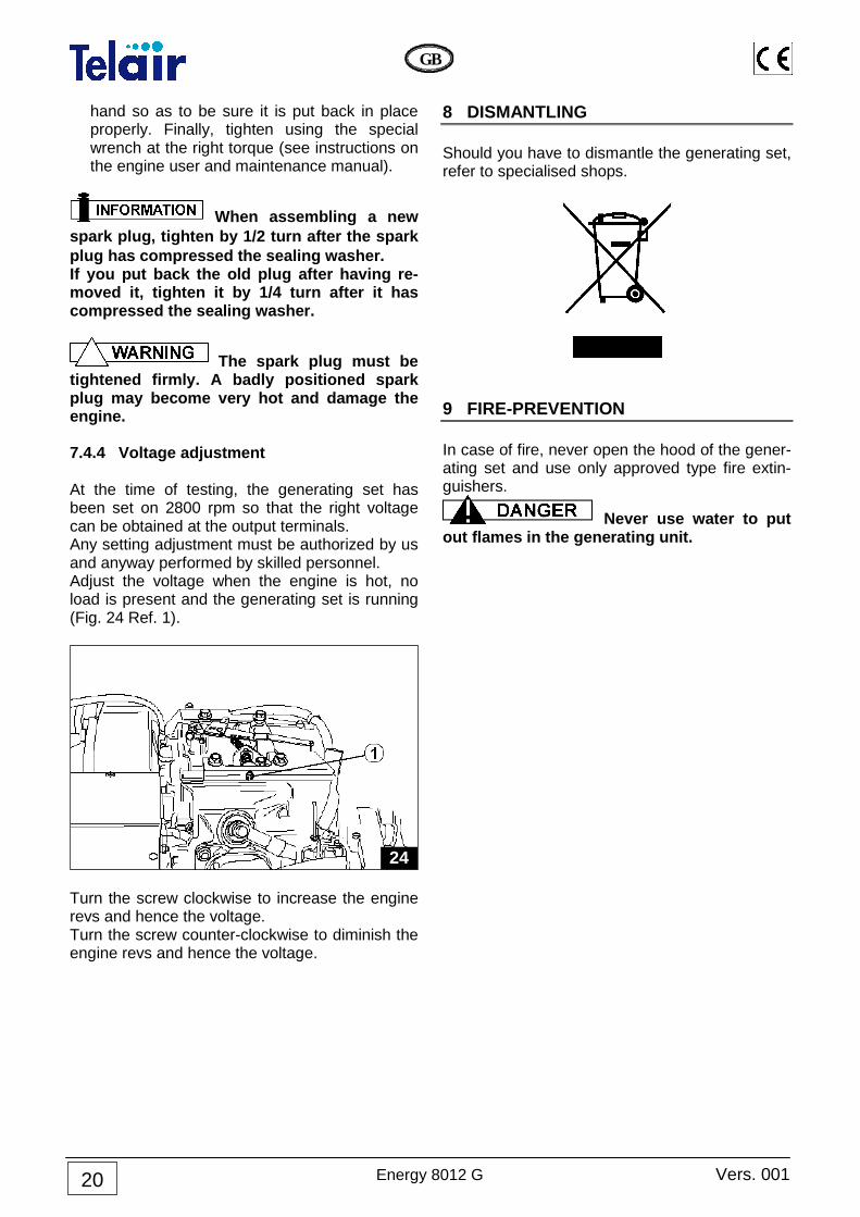
The spark plug must be tightened firmly. A badly positioned spark plug may become very hot and damage the engine. 7.4.4 Voltage adjustment At the time of testing, the generating set has been set on 2800 rpm so that the right voltage can be obtained at the output terminals. Any setting adjustment must be authorized by us and anyway performed by skilled personnel. Adjust the voltage when the engine is hot, no load is present and the generating set is running (Fig. 24 Ref. 1).
Turn the screw clockwise to increase the engine revs and hence the voltage. Turn the screw counter-clockwise to diminish the engine revs and hence the voltage.
8 DISMANTLING Should you have to dismantle the generating set, refer to specialised shops.
9 FIRE-PREVENTION In case of fire, never open the hood of the gener-ating set and use only approved type fire extin-guishers.
Never use water to put out flames in the generating unit.
24

Vers. 001 Energy 8012 G
GB
21
GENERAL WARRANTY TERMS
TELAIR guarantees its products against any material and/or manufacturing faults and defects. The entitlement to warranty cover for new engines i s valid for a period of 24 months from the time of handing over to the end user, or for a maxi-mum of 2000 operating hours, whichever of these lim its is reached first. In all cases the warranty period shall lapse no later than 26 months (28 months if delivered outside Europe) after delivery ex factory. For electric and hydraulic components, pipes, belts , sealing elements, in-jection nozzles, clutches, gear boxes, the warranty term is 12 months from the time of handing over to the end user, or for a maximum of 2000 operat-ing hours, whichever of these limits is reached fir st. In all cases the war-ranty period shall lapse no later than 14 months (1 6 months if delivered outside Europe) after delivery ex factory. In any case, the costs of lubricants and consumables shall be charged. Any transport expenses shall be intended as to be covered by the purchaser; the same applies to any expenses connected with inspections requested by the customer and accepted by TELAIR . In any case, the costs of lubricants and consumables shall be charged. The manufacturer’s warranty shall only be valid if: • the customer has carried out any routine maintenance according to the rec-
ommended schedule and has promptly visited the nearest after-sale centre if required.
• the customer can produce a document showing the date of sale (invoice or receipt).
Such document will have to be kept with care and be intact when produced to the TELAIR After-Sales centre on requesting service.
In any case, the purchaser shall not be entitled to: • terminate the contract; • claim damages to persons or property; • ask that the warranty be extended in the event of product defects or malfunc-
tioning.

Energy 8012 G Vers. 001
GB
22
WIRING DIAGRAM ENERGY 8012 GAS
PIN
K
GR
EY
RE
D
BL
AC
K
BR
OW
N
YE
LL
OW
PU
RP
LE
BL
UE
WH
ITE
GR
EE
N
BR
OW
N
WH
ITE
YE
LL
OW
BL
UE
GR
EE
N
OR
AN
GE
PIN
K
BL
AC
K
RE
D
BL
AC
K
RE
D
OR
AN
GE
PIN
K
WH
ITE
WH
ITE
GR
EY
GR
EY
YE
LL
OW
RE
D
WH
ITE
BL
UE
GR
EE
N

Vers. 001 Energy 8012 G
GB
23
Des
crip
tion
4 A
fuse
Sum
mer
/win
ter
char
ge N
TC
pro
be
Sta
rter
Igni
tion
coil
Exc
itatio
n la
mp
GA
S s
olen
oid
valv
e
Pre
ssur
e re
duce
r
Eng
ine
oil f
loat
Cho
ke th
erm
ocou
ple
prob
e
Eng
ine
ther
moc
oupl
e pr
obe
Fue
l res
erve
floa
t
Pos
.
12
13
14
15
16
17
18
19
20
21
22
Des
crip
tion
Ele
ctro
nic
cont
rol p
anel
Con
trol
pan
el c
onne
ctor
Sta
rt-u
p re
lay
Ele
ctro
nic
card
Pre
ssur
e re
duce
r co
nnec
tor
Rot
or
Alte
rnat
or
Sta
tor
Fue
l res
erve
con
nect
or
Pow
er te
rmin
al b
oard
80 A
fuse
Pos
.
1 2 3 4 5 6 7 8 9 10
11

Energy 8012 G Vers. 001
GB
24
DRAWING FOR SPARE PARTS LIST ENERGY 8012 GAS

Vers. 001 Energy 8012 G
GB
25

Energy 8012 G Vers. 001
GB
26

Vers. 001 Energy 8012 G
GB
27
Pos. Code Q.tà Descrizione
Description
Dèsignation
Bezeichnung
Denomination
Descripcion
1 03895 N. 1 Cofano superiore
Upper hood Capot supérieur
Obere Haube Bovenste kap Capo superior
2 00632 N. 7 Antivibrante
Vibration damper
Antivibratoire Schwingungsdämpfendes
Element
Trillingsdemper Anti-vibrador
3 01671 N. 2 Staffa ancoraggio
Anchor clamp Bride de fixation
Befestigungsbügel Verankeringsbeugel Estribo de anclaje
4 03805 N. 1 Tassello Portacavi Gas
Gas cable holder Serre-câbles Gaz
Aufnahme Kabel/Gassch.
Steunprofiel voor sno-eren/gasslang
Pasador Porta-cables Gas
5 03904 N. 1 Isolante Superiore Cofano
Upper hood insulation Isolation supérieure coffre Isolierung für obere Haube
Isolatie boven voor kap Aislante Superior Capó
6 03906 N. 1 Isolante Sinistro Cofano
Left hood insulation Isolation Gauche Coffre
Isolierung links für Haube Isolatie links voor kap
Aislante Izquierdo Capó
7 03907 N. 1 Isolante Posteriore Cofano
Rear hood insulation Isolation Arrière Coffre
Isolierung hinten für Haube Isolatie achter voor kap Aislante Trasero Capó
8 03905 N. 1 Isolante Destro Cofano Right hood insulation
Isolation Droite Coffre Isolierung rechts für Haube
Isolatie rechts voor kap Aislante Derecho Capó
9 03894 N. 1 Basamento cassa
Case base Base de la caisse
Kasten-Grundrahmen Onderstel kast
Base caja
10 03903 N. 1 Isolante Basamento
Base insulation Isolation Base
Isolierung für Grundrahmen Isolatie voor onderstel
Aislante Base
11 03809 N. 1 Barriera Antirumore Poste-
riore Rear antinoise barrier
Barrière anti-bruit Arrière Lärmbarriere hinten
Geluidsbarrière achter Barrrera Anti-ruido Trasero
12 03807 N. 1 Barriera Antirumore Destra
Right antinoise barrier Barrière Antibruit Droite
Lärmbarriere rechts Geluidsbarrière rechts
Barrrera Anti-ruido Derecha
13 01829 N. 1 Lamiera di chiusura sportel-
lo Door closing plate
Tôle de fermeture de porte Türblech
Afdekplaat deurtje Chapa cierre puerta
14 01224 N. 1 Serratura
Lock Serrure Schloss
Slot Cerradura
15 01830 N. 1 Convogliatore marmitta
Muffler conveyor
Convoyeur pot d’échappement
Auspufftopf-Leitblech
Geleider knaldemper Transportador silenciador
escape
16 01833 N. 1 Piastrina di scarico
Exhaust plate Plaquette d’échappement
Auslassplatte Uitlaatplaatje
Chapa de descarga
17 01827 N. 1 Chiusura convogliamento
marmitta Muffler conveyance closure
Fermeture du convoyeur pot d’échappement
Verschluss des Auspufftopf-Leitblechs
Afdekking geleider knal-demper
Cierre transportador silen-ciador escape
18 01061 N. 1 Marmitta Muffler
Pot d’échappement Auspufftopf
Knaldemper Silenciador de escape
19 01178 N. 1 Fascetta Clamp
Collier Schelle
Bandje Abrazadera
20 02058 N. 2 Rondella piana Plain washer
Rondelle plate Flachscheibe
Platte onderlegring Arandela plana
21 02057 N. 1 Rete metallica Wire netting
Grille métallique Metallgitter
Metalen rooster Red de alambre
22 01177 N. 1 Terminale di scarico
Muffler end pipe
Partie terminale pot d’échapp.
Auspuff-Endrohr
Uiteinde uitlaat Tubo de descarga
23 03742 N. 1 Staffa Supporto Alternatore Alternator support bracket
Bride Support Alternateur Tragbügel für Lichtmaschine
Steunbeugel voor dynamo Estribo Soporte Alternador
24 01432 N. 1 Tappo olio
Oil plug Bouchon de l’huile
Ölschraube Oliedop
Tapon aceite
Energy 8012 G Vers. 001
GB
28
Pos. Code Q.tà Descrizione
Description
Dèsignation
Bezeichnung
Denomination
Descripcion
25 00980 N. 1 Raccordo olio motore YA-
MAHA YAMAHA motor oil fitting
Raccord huile moteur YA-MAHA
Ölanschluss für YAMAHA-Motor
Oliekoppeling YAMAHA motor
Empalme aceite mot. YA-MAHA
26 02115 N. 1
Guarniz 14X20X1.5 AL-LUMINIO
Gasket 14X20X1.5 ALU-MINUM
Joint 14X20X1.5 ALUMI-NIUM
Dichtung 14X20X1.5 ALUMINIUM
Afdichting 14X20X1.5 ALUMINIUM
Junta 14X20X1.5 ALU-MINIO
27 01409 N. 1 Scatola filtro aria
Air filter box Boîtier du filtre à air
Luftfiltergehause Behuizing luchtfilter
Cajà filtro aire
28 02812 N. 1 Rete porta filtro Filter holding net
Filet porte-filtre Filtertragnetz
Filterhoudernet Red porta-filtro
29 02060 N. 1 Filtro aria
Air cleaner Filtre à air Luftfilter
Luchtfilter Filtro aire
30 02271 N. 1 Coperchio filtro aria
Air filter lid Couvercle du filtre à air
Luftfilterdeckel Kap luchfilter
Tapa filtro aire
31 04030 N. 1 Regolatore dell’Alternatore
Alternator regulator Régulateur de l'Alternateur Regler der Lichtmaschine
Regelaar dynamo Regulador del Alternador
32 03928 N. 1 Staffa Sostegno Regolato-
re Regulator bearing bracket
Bride de Support du Régu-lateur
Tragbügel für Regler
Steunbeugel voor regelaar Estribo Soporte Regulador
33 02314 N. 1 Termostato 45° Thermostat 45°
Thermostat 45° Thermostat 45°
Thermostaat 45° Termostato 45°
34 01128 N. 1 Termostato 90° Thermostat 90°
Thermostat 90° Thermostat 90°
Thermostaat 90° Termostato 90°
35 01176 N. 1 Motore YAMAHA YAMAHA motor
Moteur YAMAHA Motor YAMAHA
YAMAHA motor Motor YAMAHA
36 02743 N. 1 Candela Plug
Bougie Zündkerze
Bougie Bujia
37 04031 N. 1 Cavo raccordo GAS-8012
GAS-8012 fitting cable
Câble raccord GAS-8012 Verbindungskabel GAS-
8012
Verbindingskabel GAS-8012
Cable de empalme GAS-8012
38 03796 N. 1
Cavo 5 m da generatore a Pannello di controllo
5 m cable from generating set to control panel
Câble 5 m du Générateur au Panneau de Contrôle 5 m Kabel von Generator
zu Bedienpanel
5 m kabel van generator naar bedieningspaneel
Cable 5 m de generador a panel de control
39 03797 N. 1
Cavo 7 m da generatore a Pannello di controllo
7 m cable from generating set to control panel
Câble 7 m du Générateur au Panneau de Contrôle 7 m Kabel von Generator
zu Bedienpanel
7 m kabel van generator naar bedieningspaneel
Cable 7 m de generador a panel de control
40 03798 N. 1
Cavo 10 m da generatore a Pannello di controllo
10 m cable from generat-ing set to control panel
Câble 10 m du Générateur au Panneau de Contrôle
10 m Kabel von Generator zu Bedienpanel
10 m kabel van generator naar bedieningspaneel
Cable 10 m de generador a panel de control
41 03799 N. 1
Cavo 15 m da generatore a Pannello di controllo
15 m cable from generat-ing set to control panel
Câble 15 m du Générateur au Panneau de Contrôle
15 m Kabel von Generator zu Bedienpanel
15 m kabel van generator naar bedieningspaneel
Cable 15 m de generador a panel de control
42 03790 N. 1
Pannello di controllo E-NERGY 8012 G
ENERGY 8012 G control panel
Tableau/contrôle ENERGY 8012 G
Bedienpanel ENERGY 8012 G
Schakelpaneel ENERGY 8012 G
Panel de control ENERGY 8012 G
43 03763 N. 1 Lampada 12 V / 3 W
12 V / 3 W lamp Lampe 12 V / 3 W Lampe 12 V / 3 W
Lamp 12 V / 3 W Bombilla 12 V / 3 W

Vers. 001 Energy 8012 G
GB
29
Pos. Code Q.tà Descrizione
Description
Dèsignation
Bezeichnung
Denomination
Descripcion
44 03765 N. 1 Portalampade Lamp holder
Douilles Lampenhalterung
Lamphouder Portabombilla
45 02884 N. 1 Fusibile 80 A
80 A fuse Fusible 80 A
80 A Sicherung Zekering 80 A Fisible 80 A
46 02883 N. 1 Potafusibile 80 A 80 A fuse carrier
Tableau des fusibles 80 A 80 A Sicherungshalter
Zekeringhouder 80 A Portafusible 80 A
47 01405 N. 2 Morsetto LEGRAND 2x35 LEGRAND 2x35 terminal
Borne LEGRAND 2x35 Klemme LEGRAND 2x35
Aansluitklem LEGRAND 2x35
Borne LEGRAND 2x35
48 04032 N. 1 Cablaggio + Circuito stam-
pato Wiring + Printed circuit
Câblage + Circuit imprimé Verkabelung + Gedruckte
Schaltung
Bedrading + Gedrukte schakeling
Cableado + Circuito Im-preso
49 04033 N. 1 Cablaggio di potenza
Power wiring Câblage de puissance
Leistungskabel Vermogensbedrading Cableado de potencia
50 03823 N. 1 Fondo Scatola di Coman-
do Control box bottom
Base Boîtier de Commande
Boden der Steuerbox
Bodem besturingskast Fondo escala de Mando
51 03440 N. 4 Distanziale Esagonale
M3x8 Hexagonal M3x8 spacer
Entretoise Hexagonale M3x8
Distanzstück Sechskant M3x8
Zeskantafstandshouder M3x8
Separador Hexagonal M3x8
52 00235 N. 1 Zoccolo per Relè 12 V/70 A
Base for 12 V/70 A relay Culot pour Relais 12 V/70 A Sockel für Relais 12 V/70 A
Sokkel voor relais 12 V/70 A Zócalo para Relé 12 V/70 A
53 00093 N. 1 Relè 12 V/70 A 12 V/70 A Relay
Relais 12 V/70 A Relais 12 V/70 A
Relais 12 V/70A Rele 12 V/70 A
54 03822 N. 1 Scatola di Comando Control box
Boîtier de Commande Steuerbox
Besturingskast Caja de Mando
55 01603 N. 1
Piastra fissaggio Potafusi-bile 4 A
Fastening plate for 4 A fu-se carrier
Plaque de fixation tableau des fusibles 4 A
Befestigungsplatte 4 A Si-cherungshalter
Bevestigingsplaat Zeker-inghouder 4 A
Placa fijación Portafusible 4 A
56 01605 N. 1 Potafusibile 4 A 4 A fuse carrier
Tableau des fusibles 4 A 4 A Sicherungshalter
Zekeringhouder 4 A Portafusible 4 A
57 02688 N. 1 Fusibile 4 A
4 A fuse Fusible 4 A
4 A Sicherung Zekering 4 A Fisible 4 A
58 03764 N. 1 Spia verde
Green warning light Voyant vert
Grüne Kontrollleuchte Groen controlelampje
Piloto verde
59 00931 N. 2 Rondella in alluminio Aluminium washer
Rondelle en aluminium Alu-Scheibe
Onderlegring van alumi-nium
Arandela aluminio
60 01936 N. 1 Prolunga Extension
Rallonge Verlängerung
Verlengstuk Prolonga
61 00810 N. 1 Tappo Cap
Bouchon Kappe
Dop Tapon
62 00478 N. 1 Raccordo 90° 1/8 MF 1/8 MF union elbow
Raccord 90° 1/8 MF Anschlussstuck 90° 1/8 MF
Koppeling 90° 1/8 MF Empalme 90° 1/8 MF
63 04034 N. 1 Statore alternatore
Alternator stator Stator de l’alternateur
Stator der Lichtmaschine Stator dynamo
Estator alternador
64 04035 N. 1 Rotore alternatore
Alternator rotor Rotor de l’alternateur
Rotor der Lichtmaschine Rotor dynamo
Rotor alternador
65 00299 N. 1 Motore EL. 12 V 0,30 kW El. Motor 12 V 0.30 kW
Moteur él. 12 V 0,30 kW Elektromotor 12 V 0,30 kW
El. motor 12 V 0,30 kW Motor el. 12 V 0,30 kW
66 03739 N. 1 Flangia attacco Alternatore Alternator connecting flange
Bride de fixation de l'Alternateur
Befestigungsflansch für Lichtmaschine
Bevestigingsflens dynamo Brida conexión Alternador

Energy 8012 G Vers. 001
GB
30
Pos. Code Q.tà Descrizione
Description
Dèsignation
Bezeichnung
Denomination
Descripcion
67 03727 N. 1 Corona Dentata
Ring gear Couronne dentée
Zahnkranz Tandkrans
Corona Dentada
68 03773 N. 1 Mozzo Flangiato
Flanged hub Moyeu à bride Flanschnabe
Flensnaaf Cubo Embridado
69 01023 N. 1 Ventola
Fan Ventilateur Lüfterrad
Ventilator Ventilador
70 01431 N. 1 Fusione ATR 2503/C1 ATR 2503/C1 Casting
Moulage ATR 2503/C1 Gussteil ATR 2503/C1
Gietwerk ATR 2503/C1 Fundicion ATR 2503/C1
71 05522 N. 4 Vite M 6x100
M 6x100 Screw Vis M 6x100
Schraube M 6x100 Schroef M6x100 Tornillo M 6x100
72 01351 N. 1 Miscelatore Gigleur 2,7 Gicleur 2.7 mixer
Mélangeur Gigleur 2,7 Mischer Gigleur 2,7
Menger Gigleur 2,7 Mezclador Gigleur 2,7
73 03834 N. 1 Raccordo GAS a 90°
GAS union elbow Raccord GAZ à 90° GAS Anschluss 90°
GAS aansluiting 90° Conexión GAS a 90º
74 03855 N. 1 Tubo raccordo GAS
GAS union pipe Tuyau de raccord GAZ GAS Anschlussleitung
GAS aansluitpijp Tubo conexión GAS
75 03422 N. 1 Anello di serraggio
Locking ring Bague de serrage
Arretierring Klemring
Anillo de apretado
76 03423 N. 1 Ghiera di serraggio
Locking ring nut Douille de serrage
Befestigungsschraube Klemmoer
Virola de apretado
77 04042 N. 1 Raccordo uscita GAS GAS output fitting
Raccord sortie GAZ Anschluss Ausgang GAS
GAS uitlaatkoppeling Conexión salida GAS
78 00931 N. 1 Rondella in alluminio Aluminium washer
Rondelle en aluminium Alu-Scheibe
Onderlegring van alumi-nium
Arandela aluminio
79 02292 N. 1 Bobina Choke 12 V / 18 W
Choke 12 V / 18 W coil
Bobine étrangleur 12 V / 18 W
Spule Choke 12V/18V
Chokespoel 12 V / 18 W Capuchón Choke 12 V / 18
W
80 01349 N. 1 Riduttore Pressione GAS
GAS pressure reducer Manodétendeur GAZ GAS Druckreduzierer
GAS drukregelaar Reductor Presión GAS
81 01344 N. 1 Bobina GAS 12 V GAS 12 V coil
Bobine GAZ 12 V Spule GAS 12 V
Gasspoel 12 V Capuchón GAS 12 V
82 05570 N. 1 Raccordo ingresso GAS
GAS input fitting Raccord d'admission GAZ Anschlusss Eingang GAS
GAS inlaatkoppeling Conexión entrada GAS

Vers. 001 Energy 8012 G
GB
31
Notes
...............................................................................................................................................................
...............................................................................................................................................................
...............................................................................................................................................................
...............................................................................................................................................................
...............................................................................................................................................................
...............................................................................................................................................................
...............................................................................................................................................................
...............................................................................................................................................................
...............................................................................................................................................................
...............................................................................................................................................................
...............................................................................................................................................................
...............................................................................................................................................................
...............................................................................................................................................................
...............................................................................................................................................................
...............................................................................................................................................................
...............................................................................................................................................................
...............................................................................................................................................................
...............................................................................................................................................................
...............................................................................................................................................................
...............................................................................................................................................................
...............................................................................................................................................................
...............................................................................................................................................................
...............................................................................................................................................................
...............................................................................................................................................................

Energy 8012 G Vers. 001
GB
32
Contro Copertina
Telair
Top Related