


Languages
Pages
Legal


Bulletin C 1.4.43
Dean Pump® Heavy Duty,
High Temperature Process Pumps
R4140TelescopingGuard
R4140C-Face MotorSupport

Dean Pump® Series R4000 Centrifugal Process Pumps• Capacities to 5000 GPM (1135 m3/hr)
• Heads to 800 feet (245 m)
• Pumping temperatures to 850°F (454°C)
• Working pressures to 500 PSIG (3445 kPa)
ExperienceDean Pump is recognized as the industry leader in the design and manufacture of horizontal hot oil/hot water centrifugal process pumps used extensively in the following industries: chemical and petrochemical plants, power plants, plastics, heattransfer OEMs, commercial (hospitals, universities, laboratories), government facilities,pharmaceutical, and food processing.
Dean Series R centrifugal process pumps are designed to insure long, continuous service life at low cost. Each phase in the production of these pumps is meticulouslymonitored by an independent quality control department.
Pump SizesThe Dean Series R pump is an end-suction, center line supported, back pull out designregularly available in 27 sizes and divided into four size classifications:
• the R4140 Series in 17 sizes
• the R4170 Series in 3 sizes
• the R4180 Series in 5 sizes
• the R4240 Series in 2 sizes
MaterialsStandard materials of construction include carbon steel and 316SS. (StandardMaterials of Construction chart is available on Page 3).
Parts InterchangeabilityThe Series R provides the ultimate in standardization. With wide parts interchange-ability among pump sizes, fewer parts are required for inventory. A complete stock ofspare parts is readily available from Dean Pump or its network of stocking distributors,thereby reducing shipping time to a minimum.
Shaft SealingDean Pump offers a broad line of mechanical seals and standard packing sets to solvethe most difficult sealing problems. Jacketed standard bore (stuffing box), and largetaper bore, seal chambers are available for specific applications.
2

63
MECHANICAL DESIGN SPECIFICATIONSDirection of Rotation (Viewed from Coupling End) . . . . . . . . . . . . . . . . . . . . . .CCWCasing Thickness, Minimum . . . . . . . . . . . . . . . . . . . . . . . . . . . . . . . . . . . .5/16"
Corrosion Allowance . . . . . . . . . . . . . . . . . . . . . . . . . . . . . . . . . . . . . .1/8"Impeller — Standard . . . . . . . . . . . . . . . . . . . . . . . . . . . . . .Single Plane Balanced
Optional Extra . . . . . . . . . . . . . . . . . . . . . . . . . . . . . . Dynamically BalancedFlanges — ANSI Rating . . . . . . . . . . . . . . . . . . . . . . . . . . . . . . . . . . . . .Class 300
Facing . . . . . . . . . . . . . . . . . . . . . . . . . . . . . . . . . . . .Standard Raised FaceOptional Extra . . . . . . . . . . . . . . . . . . . . . . . . . . . . . . . . . .Ring Type Joint
Finish . . . . . . . . . . . . . . . . . . . . . . . . . . . . . . . . . . . . . . . . . . . . . . .125 RaSeal Chamber & Bearing Housing Jacket Pressure, Maximum . . . . . . . . . . .125 psigSuction Pressure, Maximum . . . .Max. Working Pressure Less Pump Developed Head
† Carbon Steel with Cast Iron trim. Also available with 316SS trim.
WARNING: Use the “Allowable Working Pressure VS. Pumping Temperature” chart (below,right) to determine the allowable working pressure at any allowable pumpage temperature forthe material of construction selected.
MATERIAL MAXIMUM PUMPING TEMPERATURE HYDROSTATIC TEST PRESSURECLASS WORKING PRESSURE MINIMUM MAXIMUM R4140/R4170 R4180/R424040† 500 psig @ 650°F -20°F 800°F @ 350 psig 850 75050 500 psig @ 100°F -20°F 850°F @ 305 psig psig psig
R4140 R4170 R4180 R4240Horsepower Rating — Maximum
@ 3500 rpm 100 200 250 –@ 1750 rpm 40 100 125 300@ 1160 rpm 25 – 75 200
Bearings, Type Ball Bearings, Oil LubricatedThrust Bearing (Angular Contact Pair) 7309BG 7311BG 7312BG 7317BGRadial Bearing 6309 6311 6312 6316
Approximate Oil Capacity of Bearing Housing 41 oz 36 oz 64 oz 120 ozSeal Chamber Dimensions (Large Taper Bore)
Length (Depth) 3" 3" 41/2" 47/8"Inside Diameter (Bore Diameter) 31/2" 37/8" 41/4" 5"
Shaft Sleeve Diameter 13/4" 21/8" 21/4" 3"Standard Bore (Stuffing Box) Dimensions
Length (Depth) 3" 3" 37/8" 41/8"Inside Diameter (Bore Diameter) 21/2" 27/8" 31/4" 4"Shaft Sleeve Diameter 13/4" 21/8" 21/4" 3"Lantern Gland Width 5/8" 5/8" 3/4" 1"Lantern Gland to Open End of Stuffing Box 11/2" 11/2" 11/2" 23/8"
Packing Size, Square 3/8" 3/8" 1/2" 1/2"Number of Rings with Lantern Ring 6 6 6 6Spacing 3G3 3G3 3G3 3G3Number of Rings Lantern Omitted 7 8 7 8
Pump Shaft DimensionsSpan Between Bearings C to C 6" 515/16" 81/4" 103/16"Span Between Radial Bearing C and Impeller C 8" 83/16" 103/4" 125/16"Diameter at Coupling 11/8" 15/8" 15/8" 23/8"Diameter Between Bearings 21/8" 25/8" 23/4" 4"Diameter at Impeller 11/8" 11/4" 11/2" 21/4"
L3/D4
Sleeved 101 44 78 36Solid 55 27 26 23
L LL L
*GPM Flow Rate of Cooling Water Based on 70oF (21°C) Inlet Temp
Seal Chamber Temperature VS. Pumping Temperaturewith respect to the GPM of cooling water flowing through
the cooling jacket surrounding the seal chamber.
Specifications are subject to change without notice
PUMPING TEMPERATURE –°F
PUMPING TEMPERATURE – °C.
SEAL
CHAM
BER
TEMP
ERAT
URE °
C
100 150 200 250 300 350 400 450
200 300 400 500 600 700 800
350
300
250
200
150
100
50
180
160
140
120
100
80
60
40
20
0
1 2 3 4 5
4 8
11 15 19
COOLING WATER FLOW RATE °
C
SEAL
CHAM
BER
TEMP
ERAT
URE °
F
GPM
1/min
MATERIAL SPECIFICATIONS (REFER TO NUMBERS IN PARENTHESES)
Pumping Temperature - °F
R4000 Series Pumps – Allowable Working Pressure VS Pumping TemperaturePumping Temperature - °C
-50 50 100 150 200 250 300 350 400 450
4000
3500
3000
2500
2000
1500
1000
500
0
Carbon Steel (Class 40)
Carbon SteelM
ax. Tem
p.
316SS (Class 50)
316SS Max. Tem
p.
-100 100
100
200
200
300
300
400
400
500
500
600 700 800 90000
Minimum
Tem
perature Limit - 20
Deg. F.
Working
Pressure - P
.S.I.G.
Working
Pressure - K
Pa
(1) Cast Iron (9) AISI—304SS(2) AISI 1020 (10) Alloy Steel —125,000 TS. 100,000 YP(3) 316SS — ASTM #A744 Grade CF8M (11) Grafoil — Registered trademark of Union Carbide Corp.(4) AISI 4140, ASTM #A193-B7 Steel (12) Manila Paper(5) ASTM #A194 Grade 2 Steel (13) Fibre Sheet — Non-Asbestos Fibre(6) ASTM #A216 Grade WCB Cast Steel ( -20 + 800°F ) (14) Buna N Rubber(7) Hardened Iron (15) Steel Finned, Stainless Steel Tube with Steel End Fittings(8) AISI—316SS (16) Ductile Iron — ASTM-A536 Class 65-45-12
SEAL CHAMBER PRESSURE - R4000 SERIES PUMPS**With Impeller Balance Holes—Seal Chamber Pressure Equals Pump Suction Pressure Plus .06 x Pump Developed Pressure in PSI Without Impeller Balance Holes—Seal Chamber Pressure Equals Pump Suction Pressure Plus .75 x Pump Developed Pressure in PSI
Pumps are normally furnished with balance holes
Part No. Part Name Carbon Steel 316SS(Cl. 40) (Cl. 50)
3 Impeller C.I. (1) 316 (3)*4 Impeller Key Steel (2) 316 (8)5 Casing Steel (6) 316 (3)5A Casing Drain Plug Steel (2) 316 (8)5C Casing Stud Nut Steel (5)5D Casing Stud Steel (4)*6 Casing Back Cover Ring Iron (7) 316 (3)6A Casing Ring Iron (7) 316 (3)7 Cradle Spacer D.I. (16)7A Bull’s Eye Oil Level Indicator Steel & Glass7G Spacer to Bearing Housing Capscrew Steel (2)9 Bearing Housing Foot C.I. (1)
*10 Shaft Sleeve 316 (8)*10K Shaft Sleeve Key 304 (9)*12 Impeller Bolt (Nut on R4170) Steel (2) 316 (8)*12A Impeller Washer Steel (2) 316 (8)*12B Impeller Lock Washer 316 (8)*12C Impeller Washer Pin 304 (9) 316 (8)13 Seal Chamber Gland 316 (8)
Packing Gland Steel (6) 316 (3)14 Gland Stud Steel (4) 304 (9)15 Gland Nut Steel (5) 304 (9)*17 Lantern Ring C.I. (1) 316 (3)22 Casing Back Cover Steel (6) 316 (3)
*22A Back Cover to Cradle Cap Screw Steel (2)*25 Radial Bearing —*25A Thrust Bearing —*26 Bearing Housing C.I. (1)*27 Seal Ring C.I. (1)*28 Bearing End Cover C.I. (1)*28A Bearing End Cover Cap Screw Steel (2)*29 Pump Shaft Steel (10) 316 (8)*31 Thrust Bearing Lock Nut Steel (2)*31A Thrust Bearing Lock Washer Steel (2)*54 Throat Bushing C.I. (1) 316 (8)56 Casing Foot C.I. (1)
*56B Casing Foot Dowel Steel (2)*75B Retaining Ring (All Except R4240) Steel*76 Labyrinth Seal—Front Bronze & Viton †�
*76A Labyrinth Seal—Rear Bronze & Viton †77 Casing Gasket Grafoil (11)
*77B End Cover Gasket Buna (14)*80 Bearing Housing Vent —*83 Motor Support (C Face) C.I. (1)*87 Impeller Ring—Back (Optional) Steel (2) 316 (3)87A Impeller Ring—Front (Optional) Steel (2) 316 (3)95A Mechanical Seal Stationary —95B Mechanical Seal Rotary —*109 Oil Cooler SS Tubing with Steel Fins *
Deno
tes pa
rts in
tercha
ngea
ble in a
ll pu
mp
sizes
of s
ame type
.�†
Registe
red
Trad
emar
k of th
e E.I. Du
Pont C
o.
STANDARD MATERIALS OF CONSTRUCTION
DEAN PUMP® R4000 CENTRIFUGAL PROCESS PUMPS

1. CASING COVER Jacketed standard bore or large taper bore. Designedto provide the best environment for the specific application and service conditions.
2. INTEGRAL ONE-PIECE CASING FLANGESFlanges dimensioned according to ASME/ANSI B16.5Class 300. Raised face flanges are standard. Ring typejoint flanges (Class 300) are available as an option.
3. SEALING FLEXIBILITYChoice of packed box or mechanical seal. Wide rangeof sealing arrangements (inside/outside, single/double,balanced/unbalanced, etc.) available to meet specificapplication and service conditions.
4. CLOSED IMPELLERAllows thermal expansion of the pump shaft at highpumping temperatures without interference of the impellerwith the casing or the casing cover. Keyed to shaft withpositive locking device. Replaceable wear rings optional.
5. SHAFT SLEEVEReplaceable “hook type” shaft sleeves provided as standard. Allows replacement of the wearing surfacewithout having to replace the pump shaft or the bearings.The design allows the shaft sleeve to expand thermally,independent of the pump shaft. The standard sleevematerial is 316SS. Sleeves of alloy construction, hard-facing, hardened chrome 11-13%, or ceramiccoatings are available as options. Solid sleeveless shaftsare also available.
6. CENTERLINE CASING SUPPORTThe pump is supported at the horizontal centerline of thecasing so that the thermal expansion of the casing will notaffect the shaft alignment.
7. CASING FEETThree different foot designs are available. The standard isa “yoke” design, available on R4140/4170 only, whichallows the pump to fit on an ASME/ANSI B73.1 baseplate (as well as Dean’s “Economy” baseplates).
The second “pedestal” design allows for mounting on API-type baseplates.
The last design is a “water-cooled” pedestal design (as shown) used specifically for severe service conditionsand applications.
8. COOLING PIPINGOptional tubing (as shown) connects the “water-cooled” pedestal design with the casing cover jacket.
Also available is optional tubing that connects the casing cover jacket with the finned tube oil cooler,and/or tubing that connects the cooled pedestal feetwith the casing cover jacket.
2
1
4
6
4
8

9. HEAVY DUTY SHAFT AND BEARINGSCarbon steel pump shaft (316SS optional) isdesigned for a maximum deflection of less than0.002” (0.05mm) at the mechanical seal faces. Theduplex mounted angular contact thrust bearings andthe single row, deep groove, radial bearing are sizedfor a 2 year minimum life and a 10 year averagelife.
10. STANDARD LABYRINTH SEALS Rugged bronze construction with Viton® O-rings.Magnetic face seals are also an option for all pumps.
11. LUBRICATION OPTIONS Oil bath lubrication is standard. The extra large oilreservoir is designed for cooler bearing operation.The bearing housing is set up to accommodate oilmist lubrication and grease lubrication as avail-able options. The finned tube oil cooler is providedas standard, to directly cool the oil for lower bearing temperature.
12. FILL PLUG Easy access to fill plugs supplied on both sides ofthe bearing housing. Designed to minimize thepossibility of overfilling.
13. ONE INCH OIL SIGHT GLASS Allows for simple and easy monitoring of oil leveland condition. The sight glass can be installed oneither side of the bearing housing, in the field, forbest location and ease of viewing. A combinationautomatic (bottle) oiler/sight glass is an availableoption.
14. BREATHER VENTA filtered bearing housing breather is standard. Anoptional expansion chamber is available that is usedwith the optional magnetic oil seals when a sealedbearing housing is desired.
15. PILOT AND BOLT HOLESThe bearing housing of the R4140 is supplied with apilot fit and four bolt holes at the motor end. Theholes allow for mounting of the telescoping couplingguard. The pilot fit also allows for use of an optional“C-Face” motor support. The support permits self-aligning of the motor shaft to the pump shaft.
13
7
12
149
8
5
13
5
10
11
15

DEAN PUMP® R4000 WITH SEAL CHAMBER COOLING AND BEARING FRAME COOLING
6
Doub
le volute casing
son
larger sizes
Optiona
l impe
ller
wea
r rin
g show
n(Casing wea
r rin
gsare stan
dard)
Positiv
e im
peller
locking de
vice
Class 30
0, raised
face flan
ges
Fully con
fined
com
pression
gasket (spiral w
ound
, con
-tro
lled compression
gaske
tis an av
ailable op
tion)
Centerlin
e mou
nted
(water coo
led pe
destals
are op
tiona
l)
Highly efficient sea
l cha
mbe
rcooling jacket con
centrated
arou
nd th
e mecha
nical sea
l
Bearing fram
e fin
ned
tube
oil cooler
Duplex
mou
nted
ang
ular
contact thrust b
earin
gs
Laby
rinth sea
ls stan
dard.
Mag
netic sea
ls op
tiona
lfor all p
ump sizes.
Top mou
nted
, filtered
brea
ther ven
t
“Hoo
k-type
”shaft sleeve
Hyd
raulically balan
ced
enclosed
impe
ller, ke
yed
to sha
ft
End-suction, to
p centerlin
e discha
rge
JACK
ETED
STA
NDA
RD BORE
(STU
FFIN
G BOX) SEA
L CH
AMBE
R
3

DEAN PUMP® R4000 WITH LARGE TAPER BORE SEAL CHAMBER
7
Doub
le volute casing
son
larger sizes
Optiona
l impe
ller
wea
r rin
g show
n(Casing wea
r rin
gsare stan
dard)
Positiv
e im
peller
locking de
vice
Class 30
0, raised
face flan
ges
Fully con
fined
com
pression
gasket (spiral w
ound
, con
-tro
lled compression
gaske
tis an av
ailable op
tion)
Centerlin
e mou
nted
(water coo
led pe
destals
are op
tiona
l)
Self-venting large tape
r bo
reseal cha
mbe
r
Bearing fram
e fin
ned
tube
oil cooler
Duplex
mou
nted
ang
ular
contact thrust b
earin
gs
Laby
rinth sea
ls stan
dard.
Mag
netic sea
ls op
tiona
l for all p
ump sizes.
Top mou
nted
, filtered
brea
ther ven
t
“Hoo
k-type
”shaft sleeve
Hyd
raulically balan
ced
enclosed
impe
ller, ke
yed
to sha
ft
End-suction, to
p centerlin
e discha
rge
LARG
E TA
PER BO
RE SEA
L CH
AMBE
R

DEAN PUMP® R4140 WITH SEAL CHAMBER COOLING AND “C-FACE” FLANGED MOTOR SUPPORT
8
Doub
le volute casing
son
larger sizes
Optiona
l impe
ller
wea
r rin
g show
n(Casing wea
r rin
gsare stan
dard)
Positiv
e im
peller
locking de
vice
Class 30
0, raised
face flan
ges
Fully con
fined
com
pression
gasket (spiral w
ound
, con
-tro
lled compression
gaske
tis an av
ailable op
tion)
Centerlin
e mou
nted
(water coo
led pe
destals
are op
tiona
l)
Highly efficient sea
l cha
mbe
rcooling jacket con
centrated
arou
nd th
e mecha
nical sea
l.Large tape
r bo
re also
ava
ilable.
Bearing fram
e fin
ned
tube
oil cooler
Duplex
mou
nted
ang
ular
contact thrust b
earin
gs
Laby
rinth sea
ls stan
dard.
Mag
netic sea
ls op
tiona
lfor all p
ump sizes.
Top mou
nted
, filtered
brea
ther ven
t
“Hoo
k-type
”shaft sleeve
Hyd
raulically balan
ced
enclosed
impe
ller, ke
yed
to sha
ft
End-suction, to
p centerlin
e discha
rge
Optiona
l “C-Fa
ce” motor
supp
ort, prov
ides self-
aligning
of the
motor sha
ftto th
e pu
mp shaft.
“C-FACE
” MOTO
R SU
PPORT

R4170
Pump Size Casing Impeller Casing Adaptor Bearing HousingCover Cradle Assembly
DEAN PUMP® PARTS INTERCHANGEABILITY OF 27 PUMP SIZES
R4140
Pump Size Casing Impeller Casing Adaptor Bearing HousingCover Cradle Assembly
1x3x8.5
3x4x8.5
4x6x8.5
2x3x10
3x4x10
4x6x10
1x2x11.5
1.5x3x13.5
2x3x13.5
3x4x13.5
1.5x3x13.5
2x3x13.5
3x4x13.5
4x6x10
6x8x12.5
2x4x15.5
3x4x15.5
4x6x15.5
6x8x15.5
8x10x15.5
Casing covers with jackets and large taper bore seal cavities are available on all pumps. Bearing housings withfinned tube oil coolers are standard on all pumps.
Bearing Housing Foot
9
1.5x3x8.5
2x3x8.5
1.5x3x10
2x3x11.5
3x4x11.5
4x6x11.5
1.5x3x11.5
R4180
Pump Size Casing Impeller Casing Adaptor Bearing HousingCover Cradle Assembly
R4240
Pump Size Casing Impeller Casing Adaptor Bearing HousingCover Cradle Assembly

HEAD CAPACITY RANGE CHARTS
800
700
600
500
400
300
200
100
00 100 200 300 400 500 600 700 800 900 1000 1100 1200 1300 1400
25 50 75 100 125 150 175 200 225 250 275
160
140
120
100
80
60
40
20
Capacity Cubic Meters Per Hour 2900 RPM - 50 Hertz
Capacity U.S. Gallons Per Minute 3500 RPM - 60 Hertz
Total
Hea
d Fee
t 350
0 RP
M - 6
0 He
rtz
Total
Hea
d Mete
rs 29
00 R
PM -
50 H
ertz
11/2 X 3 X 131/2
2 X 3 X 131/2
3 X 4 X 131/2
1X 2 X 111/2
11/2 X 3 X 111/2
3 X 4 X 10
4 X 6 X 10 #1 (R4180)
4 X 6 X 81/23 X 4 X 81/2
2 X 3 X 81/2
2 X 3 X 1011/2 X 3 X 10
1 X 3 X 81/2
11/2 X 3 X 81/2
Two Pole Motor
10
260
240
220
200
180
160
140
120
100
80
60
40
20
0
10 100 1000 6000
4 6 8 10 20 40 60 80 100 200 400 600 800
55
50
45
40
35
30
25
20
15
10
5
Capacity Cubic Meters Per Hour 1450 RPM - 50 Hertz
Capacity U.S. Gallons Per Minute 1750 RPM - 60 Hertz
Total
Hea
d Fee
t 175
0 RP
M - 6
0 He
rtz
Total
Hea
d Mete
rs 14
50 R
PM -
50 H
ertz
11/2 X 3 X 131/2
2 X 3 X 131/23 X 4 X 131/2
1X 2 X 111/2 11/2 X 3 X 111/2
3 X 4 X 104 X 6 X 10 #1 (R4180)
4 X 6 X 81/2
3 X 4 X 81/22 X 3 X 81/2
2 X 3 X 1011/2 X 3 X 10
2 X 3 X 111/2
11/2 X 3 X 81/2
1 X 3 X 81/2
4 X 6 X 10 #2 (R4140)
3 X 4 X 111/2 4 X 6 X 111/2
6 X 8 X 121/2
2 X 4 X 151/2
3 X 4 X 151/2
4 X 6 X 151/26 X 8 X 151/2
8 X 10 X 151/2
Four Pole Motor
HEAD CAPACITY RANGE CHARTS
JACKETED STANDARD BORE(STUFFING BOX) SEAL CHAMBER
LARGE TAPER BORESEAL CHAMBER
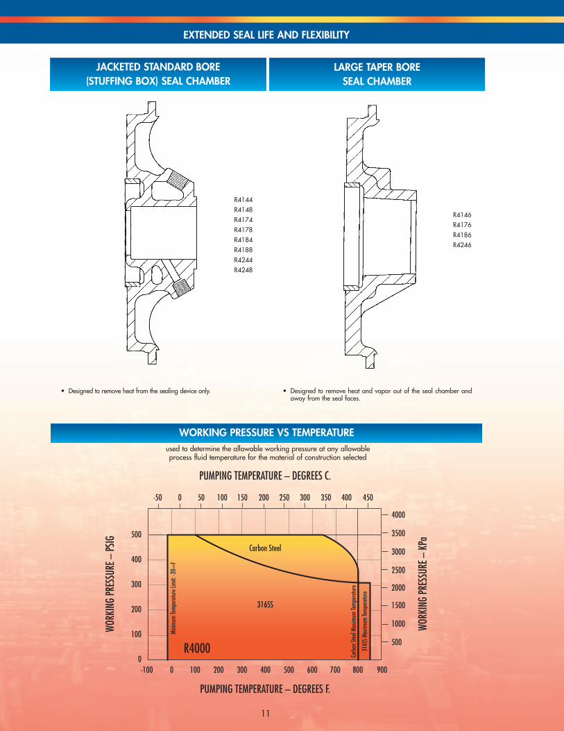
• Designed to remove heat from the sealing device only. • Designed to remove heat and vapor out of the seal chamber andaway from the seal faces.
EXTENDED SEAL LIFE AND FLEXIBILITY
R4144R4148R4174R4178R4184R4188R4244R4248
R4146R4176R4186R4246
11
R4000
PUMPING TEMPERATURE – DEGREES F.
PUMPING TEMPERATURE – DEGREES C.
WORK
ING
PRES
SURE
– PS
IG
WORK
ING
PRES
SURE
– K
Pa
-50 0 50 100 150 200 250 300 350 400 450
-100 0 100 200 300 400 500 600 700 800 900
500
400
300
200
100
0
4000
3500
3000
2500
2000
1500
1000
500
Carbon Steel
316SS
Minim
um Te
mper
ature
Limi
t: -2
0∞F
Carb
on St
eel M
axim
um Te
mper
ature
316S
S Max
imum
Temp
eratu
re
used to determine the allowable working pressure at any allowable process fluid temperature for the material of construction selected
WORKING PRESSURE VS TEMPERATURE

Frame C AB HA HBHD
HG HMD=8.25 D=10 D=11.5143T 13.25 6.50 12 45 12.00 13.75 15.25 3.75 3.88145T 13.75 6.50 12 45 12.00 13.75 15.25 3.75 3.88182T 14.63 7.50 12 45 12.00 13.75 15.25 3.75 5.25184T 15.63 7.50 12 45 12.00 13.75 15.25 3.75 5.25213T 18.13 9.50 12 45 12.00 13.75 15.25 3.75 6.0215T 19.63 9.50 12 45 12.00 13.75 15.25 3.75 6.0254T 23.13 10.75 15 52 12.38 14.13 15.63 4.13 7.0256T 24.88 10.75 15 52 12.38 14.13 15.63 4.13 7.0284T 26.88 12.63 15 52 12.38 14.13 15.63 4.13 7.75284TS25.50 12.63 15 52 12.38 14.13 15.63 4.13 7.75286T 28.38 12.63 15 52 12.38 14.13 15.63 4.13 7.75
Pump Discharge SuctionSize Size O.D. Thick. B.C. Bolts Size O.D. Thick. B.C. Bolts
A1 A2 D S X Y
1x3x8.5 1 4.875 .688 3.50 4-5/8 3 8.25 1.13 6.63 8-3/4 8.13 8.13 8.25 0 7.50 41.5x3x8.5 1.5 6.125 .813 4.50 4-3/4 3 8.25 1.13 6.63 8-3/4 8.13 8.13 8.25 0 8.50 42x3x8.5 2 6.50 .875 5 8-5/8 3 8.25 1.13 6.63 8-3/4 8.13 8.13 8.25 0 9.50 53x4x8.5 3 8.25 1.13 6.63 8-3/4 4 10 1.25 7.88 8-3/4 9 8.13 10 0 11 54x6x8.5 4 10 1.25 7.88 8-3/4 6 12.50 1.44 10.63 12-3/4 10.25 8.13 10 .63 11.50 61.5x3x10 1.5 6.125 .813 4.50 4-3/4 3 8.25 1.13 6.63 8-3/4 9 8.75 10 0 9 42x3x10 2 6.50 .875 5 8-5/8 3 8.25 1.13 6.63 8-3/4 9 8.75 10 0 9.50 53x4x10 3 8.25 1.13 6.63 8-3/4 4 10 1.25 7.88 8-3/4 10.38 8.75 10 0 11 54x6x10#2 4 10 1.25 7.88 8-3/4 6 12.5 1.44 10.63 12-3/4 11.75 10 11.50 .13 12.50 61x2x11.5 1 4.875 .688 3.50 4-5/8 2 6.5 .875 5 8-5/8 9.75 9.75 10 0 9 51.5x3x11.5 1.5 6.125 .813 4.50 4-3/4 3 8.25 1.13 6.63 8-3/4 9.75 9.75 10 0 10.50 42x3x11.5 2 6.50 .875 5 8-5/8 3 8.25 1.13 6.63 8-3/4 10.25 9.75 10 0 10.50 53x4x11.5 3 8.25 1.13 6.63 8-3/4 4 10 1.25 7.88 8-3/4 11.25 10 11.50 0 12.50 64x6x11.5 4 10 1.25 7.88 8-3/4 6 12.50 1.44 10.63 12-3/4 11.75 10.50 11.50 .38 13.50 61.5x3x13.5 1.5 6.125 .813 4.50 4-3/4 3 8.25 1.13 6.63 8-3/4 11.50 11.50 11.50 0 11 52x3x13.5 2 6.50 .875 5 8-5/8 3 8.25 1.13 6.63 8-3/4 11.50 11.50 11.50 0 11.50 53x4x13.5 3 8.25 1.13 6.63 8-3/4 4 10 1.25 7.88 8-3/4 12 11.50 11.50 0 12.50 6
Dimensions of R4140 with “Economy” Baseplate
All Dimensions in inches.
Frame C AB HA HBHD
HG HMD=8.25 D=10 D=11.5286TS27.00 12.63 15 52 12.38 14.13 15.63 4.13 7.75324T 29.88 14.75 18 58 13.00 14.75 16.25 4.75 8.75324TS28.37 14.75 18 58 13.00 14.75 16.25 4.75 8.75326T 31.38 14.75 18 58 13.00 14.75 16.25 4.75 8.75326TS29.88 14.75 18 58 13.00 14.75 16.25 4.75 8.75364T 33.13 15.63 18 58 13.75 14.75 16.25 4.75 9.88364TS31.50 15.63 18 58 13.75 14.75 16.25 4.75 9.88365T 34.13 15.63 18 58 13.75 14.75 16.25 4.75 9.88365TS32.50 15.63 18 58 13.75 14.75 16.25 4.75 9.88404TS33.50 17.50 18 60 — 14.63 16.13 4.63 11.0405TS35.00 17.50 18 60 — 14.63 16.13 4.63 11.0
6040 Guion Road • Indianapolis, IN 46254P: 317.293.2930 • TOLL-FREE: 800.801.9265 • F: [email protected] • www.deanpump.com
© 2010 MET-PRO CORPORATION
DEAN PUMP® IS A REGISTERED TRADEMARK OF MET-PRO CORPORATION 09-5900 810
Top Related