


Languages
Pages
Legal


Chapter III
Fundamentais
AOD refining is based upon:
o CO Dilution
o Mlxing
o Degassing
Each of these AOD phenomena and a reaction
mechanism are discussed herein.
A. CO Dilution
During historical stainless steel
decarburization by conventional oxygen blowing,
the atmosphere in equilibrium with the melt is
essentially puré CO at one atmosphere pressure.
Under these conditions, the amount of chromium
existing in the melt is limited by equilibrium
with a given carbon content at a given
temperature. The curves shown in Figure 2
illustrate these equilibrium effects. Any excess
of chromium is rapidly oxidized. As the carbon
content of the melt decreases, the amount of
chromium also decreases. Raising the melt
temperature raises the equilibrium chromium
concentration, but temperatures are soon reached
which are uneconomically high in terms of
refractory life.
These relations which establish the extent to
which the melt can be decarburized w.ithout
oxidizing chromium have been reported by several(21,22,23.27,28) _,
investigators . The thermodynamic
relationships are discussed in those references
and are reviewed in detail in other texts. The
oxygen' levei of the bath is controlled by the DIOK!;
stable oxide of chromium (after the more stable
oxides such as silicon and alumimim have been
removed). Equation II) shows the chemica]
equation for carbon removal together with its
equilibrium constant assuming that Cr O is the«J i
most stable oxide.
1/4 Cr O (s) + C = 3/4 Cr + CO (g)O T:
Ml
K = (PCO)
3 4(Thfire are some reservations concerninq whether
Cr O is the most stable oxide at steelmaking
temperatures; those considerations are beyond the
scope of this text.)
In similar studies for high-chromium
ferroalloys. Krivsky (1) used argon-oxygen
roixtures to study decarburization. He found that,
if argon was injected along with the oxygen, the
argon diluted the CO evolved and thereby decreased
its partial pressure. This favors the carbon-
oxygen reaction and increases greatly the amount
0.5
0.2
0.1
0.05Om
l °'02
0.01
0.005
0.0028 12 16 20
CHROMIUM %
Figure 2. Carbon - chromium equilibriun curves.
pi::
PNEUMATIC STEELMAKING - VOLUME TWO - 5
of cbromium which can be retained in the melt at
practical temperaturas.
Although equilibrium relationships provide an
adequate picture of the direction in which a
process will move, they do not indicate the actual
path or rate of the reactions. Remember that
gaseous diatomic oxygen first dissolves as
monatomic oxygen in the molten metal. Equations
[21 and 131 break down equation (11 into the two
reactions believed to be controlling the over-all
equilibrium.
1/4 Cr^O, (s) = 3/4 Cr + Oj 4
C + O = CO (g)
(2!
[31
1/4 Cr O (s) + C = 3/4 Cr + CO (g) (11O T
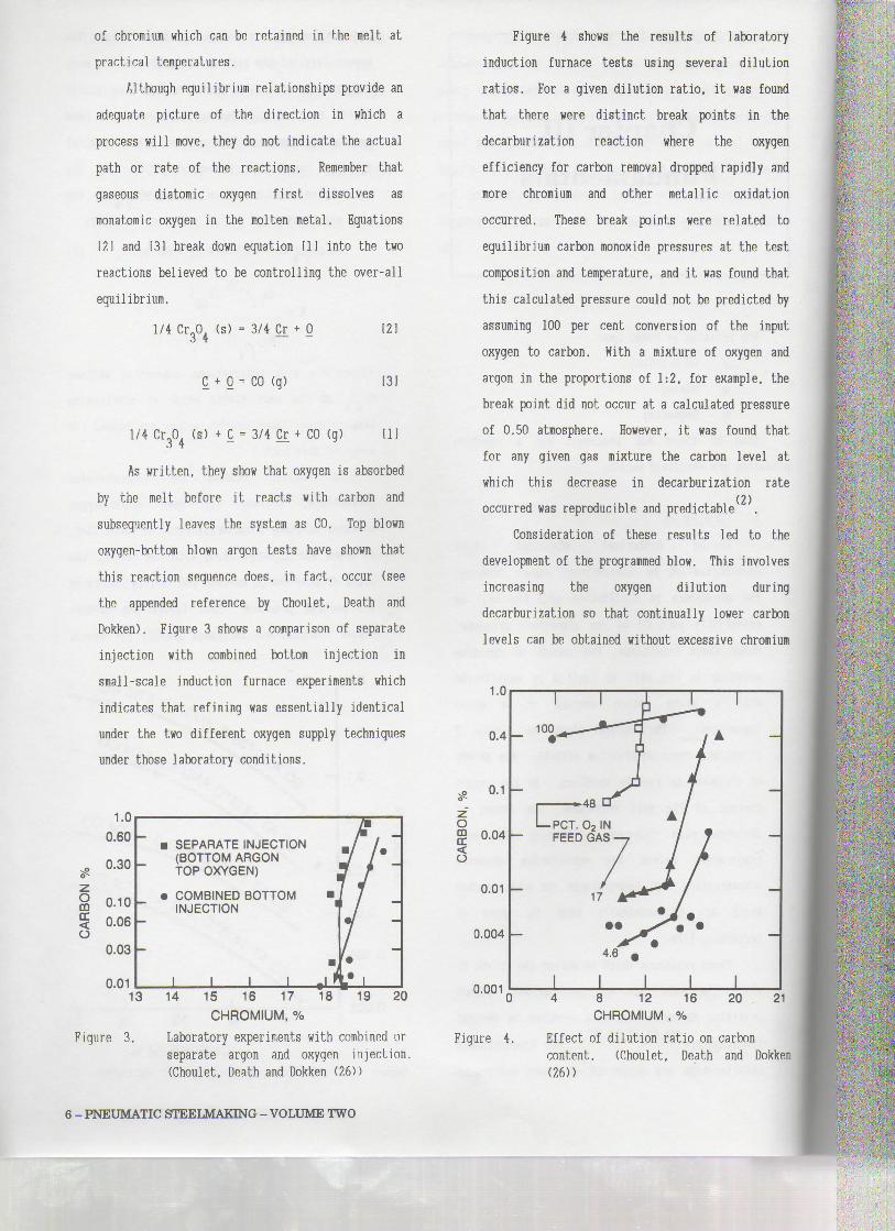
As written, they show that oxygen is absorbed
by the melt before it reacts with carbon and
subsequently leaves the systei as CO. Top blovm
oxygen-bottom blown argon tests have shown that
this reaction sequence does, in fact. occur (see
the appended reference by Choulet, Death and
Dokken). Figure 3 shows a comparison of separate
injection with combined bottom injection in
small-scale induction furnace experiments which
indicates that refining was essentially identical
under the two different oxygen supply techniques
under those laboratory conditions.
Omcc<o
1 .U
0.60
0.30
0.10
0.06
0.03
n m
• SEPARATE INJECTION(BOTTOM ARGONTOP OXYGEN) !
• COMBINED BOTTOM •INJECTION
-
l l l l__jj
W---1
9
• 113 14 15 16 17 18
CHROMIUM, %
19 20
Figure 3. Laboratory experiments with combined orseparate argon and oxygen injection.(Choulet, Death and Dokken (26))
O
o
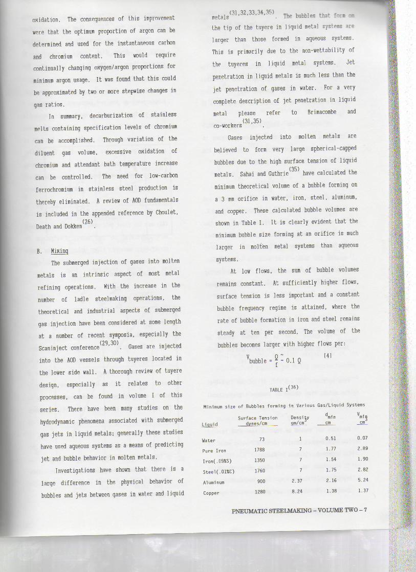
Figure 4 shows the results of laboratory
induction furnace tests using several dilution
ratios. For a given dilution ratio, it was found
that there were distinct break points in the
decarburization reaction where the oxygen
efficiency for carbon removal dropped rapidly and
more chromium and other metallic oxidation
occurred. These break points were related to
eguilibrium carbon monoxide pressures at the test
composition and temperature, and it was found that
this calculated pressure could not be predicted by
assuming 100 per cent conversion of the input
oxygen to carbon. With a mixture of oxygen and
argon in the proportions of 1:2, for example, the
break point did not occur at a calculated pressure
of 0.50 atmosphere. However, it was found that
for any given gás mixture the carbon levei at
which this decrease in decarburization rate(2)occurred was reproducible and predictable
Consideration of these results led to the
development of the programmed blow. This involves
increasing the oxygen dilution during
decarburization só that continually lower carbon
leveis can be obtained without excessive chromium
1.0
0.4
0.04
0.01
0.004
0.001
100
4̂8 cr /
l X l l4 8 12 16 20 21
CHROMIUM , %
Figure 4. Effect of dilution ratio on carboncontent. (Choulet, Death and Dokken(26))
6 - PNEUMATIC STEELMAKING - VOLUME TWO
oxidation. The consequences of this improvement
were fchat the optimum proportion of argon can be
determined and used for the instantaneous carhon
and chromium content. This would require
continually changing oxygen/argon proportions for
minimum argon usage. It was found that this could
be approximated by two or more stepwise changes in
gás ratios.
In summary, decarburization of stainless
melts containing specification leveis of chromiui
can be accomplished. Through variation of the
diluent gás volume, excessive oxidation of
chromium and attendant bath tetnperature increase
can be controlled. The need for low-carbon
ferrochromium in stainless steel production is
thereby eliminated. Â review of AOD fundamentais
is included in the appended reference by Choulet,/OC N
Death and Dokken
B. Hixing
The submerged injection of gases into molten
metais is an intrinsic aspect of most metal
refining operations. With the increase in the
number of ladle steelmaking operations, the
theoretical and industrial aspects of submerged
gás injection have been considered at some length
at a number of recent symposia, especially the(29,30) .Scanmject conference . Gases are injected
into the AOD vessels through tuyeres located in
the lower side wall. A thorough review of tuyere
design, especially as it relates to other
processes, can be found in volume I of this
series. There have been many studies on the
hydrodynamic phenomena associated with submerged
gás jets in liquid metais; generally these studies
have used aqueous systems as a means of predicting
jet and bubble behavior in molten metais.
Investigations have shown that there is a
large difference in the physical behavior of
bubbles and jets between gases in water and liquid
, . (31,32,33,34,35) _ ,,,,metais . The bubbles that for» w
the tip of the tuyere in liquid metal systens are
larger than those formed in aqueous systems.
This is primarily due to the non-wettability of
the tuyeres in liquid metal systems. Jet
penetration in liquid metais is much less than the
jet penetration of gases in water. For a very
complete description of jet penetration in liquid
metal please refer to Brimacombe and(31,35)co-workers
Gases injected into molten metais are
believed to form very large spherical-capped
bubbles due to the high surface tension of liquid(35)metais. Sahai and Guthrie ' have calculated the
minimum theoretical volume of a bubble forming on
a 3 mm orifice in water, iron, steel, aluminum,
and copper. These calculated bubble volumes are
shown in Table I. It is clearly evident that the
ninimum bubble size forming at an orifice is mch
larger in molten metal systems than aqueous
systems.
At low flows, the sum of bubble volumes
remains constant. At sufficiently higher flows,
surface tension is less important and a constant
bubble frequency regime is attained, where the
rate of bubble formation in iron and steel remains
steady at ten per second. The volume of the
bubbles becomes larger with higher flows per:
bubble = = o.l Q
(36)TABLE I
Minimum síze of Bubbles forming in Various Gas/Liquid Systems
Surface TensionLiquid dynes/cm
Water
Puré Iron
Iron(.05%S)
Steel (.01%C)
Aluminum
Copper
73
1788
1350
1760
900
1280
Densityqm/citi
1
7
7
7
2.37
8.24
amincm
0.51
1.77
1.54
1.75
2.16
1.38
mincm
0.07
2.89
1.90
2.82
5.24
1.37
;
PNEUMATIC STEELMAKING - VOLUME TWO - 7

The size of bubbles in molten iron, water,.(37,38)
and mercury was estimated by Sano and Morí
to be,
d .091 f '50 x V M 151Pl S
where d is the diameter; J, surface tension of the
liquid; P , density of the liquid; and V , bubblei S
rise velocity. Using equation !51, the average
bubble diameter for a typical AOD operation is 10
cm.By equating the energy supplied to the bath
by rising bubbles to turbulent energy losses in(39)the bath, Sahai and Guthrie predicted the
following relationship for plume velocity, U ,
161.33
where Q is the gás flowrate at the mean height and
temperature of the bath; L, the bath depth; and R,
the vessel radius. The piume velocity is the
velocity of the gas-liquid region (bubble plume)
as it rises up through the liquid. They also
equated the bubble rise velocity to the plume
velocity, and determined the following
relationship for the average recirculation speed
in the vessel, u,
u a (71,.33
The mixing time in a vessel should be
inversely proportional to the recirculation speed;
l 181t a ~u
From equations 161 and 17), it follows then that
the mixing time should be inversely proportionalJ/3
to Q .- ¥\ « Q " 191
Equation [91 should be kept in mind when reading
the experimental results of the AOD water model in
the appended reference by Masterson(41)T. Oake et ai. have done extensive
experimental studies on the coalescence and
break-up of bubbles in swarms with aqueous
systems. Their results are in excellenb agreement(37 38)
with Sano and Mori . They have also studied
the region in close proximity of the injection
point and found that bubble coalescence is
greatest there. In the vicinity right after the
bubble detaches from the nozzle, bubble
coalescence is the only phenomenon occurring.
Bubble break-up does not begin until a position 7
to 10 cm from the nozzle, which is in remarkable
agreement with Sano and Mori. Bubble coalescence
and break-up occur at an equal rate in the bath at
a height greater than 15 cm from the nozzle.
These results extrapolated to an AOD vessel
indicate that the wear around and above the tuyere
may be due to gás expansion and bubble
coalescence.
The work of Nakanishi, Fujii, and Szekeley
(42) was the first published in which mixing times
were correiated to the energy dissipation in
steelmaking vessels. They introduced the Index
for Selective Carbon Oxidation (ISCO) which is
calculated as follows:
2Q0isco = "L vQD) W
[10]
where Q is the oxygen flowrate; Q , flowrate of
diluent gás; N, weight of melt; and t, mixing
time. The first term of the ISCO Index,
2Q /(2Q+Q ), represents the partial pressure of
CO in the melt. The second term of the ISCO
Index, ÇLjt/tf, is the ratio of the oxygen supply
to the supply of carbon at the reaction site in
the melt. In the ISCO Index, the partial pressure
of CO, multiplied by the ratio of oxygen supply to
carbon supply at the reaction site, is taken to
judge the degree of selective oxidation of carbon
in the melt. The lower the value of the ISCO
Index, the greater the potential to oxidize carbon
selectively rather than some other metallic
component (e.g., Cr) of the melt.
?f:í: £3Kv
8 - PNEUMATIC STEELMAKING - VOLUME TWO

The total %Fe in the slag as a function of
the ISCO Index for various top/bottom steelmaking
processes is shown in Figure 5. Clearly, as the
ISCO índex decreases, the total %Fe in the slag
decreases. A more dramatic correlation hás been
observed in Cr losses during stainless steel
refining. Figure 6 compares Cr losses as a
function of ISCO índex for a 5-ton Q-BOP for
different operating conditions (the diluent gás
30
20co
ã 1o2Q
/
ss
x
4
4
Ty^
* >
1 ***
fl 1180-t-LDl
. "^180-t-LD
' 180-t-LD-KG
5-t-OBM/Q-BOP
235-t-OEÍM/Q-BOI>
O 50 100 150 200ISCO VALUE AT (C) = 0.05%
Figure 5. Influence of bath mixing on oxidation ofmelt. (Nakanishi, Fujii and Szekely(42))
^3)
Z
_iCO0
1 R
QLUNQ
Òu.O
ê 51303*<
T/K
,£/
Ir
/
í•D-t-AOD (,
r
Bumitomo)
0 20 40 60 80 10
ISCO VALUEFigure 6. Loss of chromium in slag for 5-ton
Q-BOP. (Nakanishi, Fujii and Szekely(42))
was not specified) to a 10-ton AOD. The decrease
in Cr losses with a decrease in ISCO Index is very
noticeable.
Recently, a 5-ton AOD water model was used to
measure mixing times as a function of gás flowrate
and tuyere placement. For a complete description
of this work, see the appended reference by(40)
Masterson
Mixing time as a function of flowrate was
empirically determined to fit the relation:
t = 18.07 Q 111
Recalling equation 191, t a Q '"", the
agreement between experimentally determined
functional dependence of the mixing time on the
flowrate, Q, is remarkable. Using equation 1111,
the mixing time in the AOD water model is 17
seconds. There is no data available on the mixing(43)
time in AOD vessels, but Kato, et ai have
measured the mixing time in a 5-ton Q-BOP of 17-20
seconds. The experimental conditions (blow rate,
number of tuyeres) were not reported, but it is
similar to an AOD vessel. and the agreement is
quite good. The agreement between predicted and
measured mixing times does support the modeling
criteria.
More tangible evidence of good mixing in the
AOD is familiar to operators in the form of
excellent slag-metal chemical and thermal
equilibrium. This excellent mixing aids in the
attainment of equilibrium during decarburization,
especially at low carbon leveis. The increased
slag-metal contact promotes predictable, high
recovery of alloying elements and rapid, efficient
desulfurization.
Stirring is known to improve the kinetics of
alloy deoxidation, permitting equilibrium
conditions to be more closely approached (44).
Extremely low oxide contents are attainable if the
oxides formed can escape prior to solidification
and i f reoxidation is prevented during casting.
PNEUMATIC STEELMAKING - VOLUME TWO - 9

C. Deqassinq
The mechanism of argon degassing is quite
similar to that of vacuum degassing. The
theoretical aspects of vacuun degassing,
particularly with respect to carbon deoxidation.
have been aptly discussed in the
literature . However, there are several
inherent differences ' ' as discussed below.
The removal of dissolved gases from steel by
argon results from (1) the effect of argon bubbles
in providing nucleation sites for reactions which
transfer the dissolved gases from the steel to the
gás phase, (2) the improved reaction kinetics
resulting from stirring. and (3) the driving force
for these reactions provided by the low partial
pressure of CO, H. and N? in the argon bubbles.
During the oxygen blow of AÇO refining,
evolving carbon monoxide supplements the argon to
assist in degassing. The CO and Ar bubbles absorb
H and N, (as well as CO up to saturation) as theyL Lrise through the bath. Argon injection causes
considerable stirring of the bath, thus improving
the kinetics of the degassing reaction by (1)
decreasing the effect of diffusion boundary layers
around the reaction sites; (2) transporting the
reaction sites to the reactants; and (3)
transporting the saturated bubbles away fron the
newly injected reaction sites.
Degassing in AOD is important not only for
the production of low gás content (especially Io»
hydrogen content) low alloy steels tat also to
control the nitrogen content in stainless steels.
Nitrogen will dissolve in steel with deletério»
effects in many instances. Conseqneatly, it is
often necessary to purge a portioa of the
dissolved nitrogen by blowing argon tlm«jfe the
bath during the latter portion of deariMrizatm
and subsequent refining. By svitdrâg frt»
nitrogen to argon at sone poiat dxríig ti»
decarburization blow and continoing to 0
during reduction and any subsequent steps, purging
of nitrogen by argon and carbon monoxide is
accomplished . In order to finish at a specific
nitrogen levei, the switch-over point from
nitrogen to argon must be determined with
reasonable accuracy.
In certain grades, on the other hand,
nitrogen is desired as a strengthening or
austenitizing agent. Production of these steels
previously required the addition of expensive
nitrogen-bearing ferroalloys; however, these
grades can now be made by alloying with gaseous
nitrogen at the end of the heat
The first commerdal use of nitrogen as a
replacement for argon in AOD refining was reported(49)
by Moffet and Saccomano in 1972. At the same(50)time, Dokken reviewed the theoretical aspects
of the use of nitrogen. Those concepts are
discussed in the following paragraphs.
While it is reasonable to use the solubility
of nitrogen in puré liquid iron for most plain
carbon steels, it is clearly unacceptable in
considering stainless grades. The effect of
deoxidizing and alloying elements on the activity
of carbon, oxygen, nitrogen, and hydrogen hás been
reported . For example, the presence of
alloying eleients such as chromium and vanadium
hinder carbon deoxidation and increased nitrogen
solubility while the presence of nickel aids the
CO reaction and decreases nitrogen solubility.
Elements such as titanium and vanadium increase
the solubility of nitrogen in steel, thus making
its removal more difficult. The formation of
stable oxides and/or nitrides inhibit the removal
of CO or H For grade 304 stainless steel, the
solubility of nitrogen after the AOD reduction
step is 0.23%.
Tbe solubility of nitrogen in ali steels is
taon to folio» Sieverfs Law:
j
l
í
ii
ZN = const. 1121
10 - PNEUMATIC STEELMAKING - VOLUME TWO

This relationship is evident from the
following reaction and its equilibrium constant:
1/2 N 2 (g)
Kl =aN . fN'%N
(131
11410.5
(
0.5
where:N represents nitrogen dissolved in the steel
a = The activity of dissolved nitrogen.N
f = The activity coefficient of dissolved nitrogen.N
%N = The weight percent of dissolved nitrogen.
L - The equilibriui constant of reaction 1.
P = The partial pressure of nitrogen, in atmospheres.N2
For the AOD, we are interested in P., of theN2
exit gás:
N2. P
+ 8Ar * Qcosystem
Q Q - Volumetric flow rate of gás injectedN2
Q = Volumetric flow rate of CO generated
Equation 1131 clearly reduces to Sieverfs Law
since f is a constant for a specific bathNchemistry and temperature. For the specific case
of nitrogen dissolving in puré liquid iron (the
binary Fe-N system), the "const." of eqn. 1121 is
K,. (Implicit in this statement is: f = ll flfor Fe-N alloys.)
(52)In puré liquid iron , the Gibb's Free
Energy for Equation (131 is:
AG^ = 860 + 5.71 T (cal/g-atom) ± 100 cal {15}
Knowlng that AG° = -RT In K at equIUbrlum, we can
derive an expression for the logarithm of R in
puré liquid iron:
log Kj - -188/T - 1.25 1161
At 1600°C (1873'K), the solubility of nitrogen in
puré liquid iron is 0.045%. In stainless steels,
the activity coefficient of nitrogen is not unity.
thus in order to use equation 13, we must
calculate f...N
The effect of alloying elements on the
solubility of nitrogen in liquid iron alloys is
shown in Figure 7. Notice that the common
intercept is the solubility of nitrogen in puré
iron discussed above.
A negative interaction coefficient indicates
that the alloy element "j" increases the
solubility (or decreases the activity) of
nitrogen. Conversely, a positive interaction
coefficient indicates that the alloy element "j"
decreases the solubility (or increases the
activity) of N.
Each curve for a specific eleient, j, on the
diagram defines an activity coefficient of
nitrogen in the ternary alloy Fe-N-j. Froni this
activity coefficient, one can determine the
interaction coefficient,
e, which describes the effect of the alloy!element, j, on the behavior of N in the steel.
For fundamental work, the reader should consult
Wada and Pehlke and thej r references.
0.20
0.16
OOcc^ 0.12
LUOcrLU°- 0.08
LU
0.04
-0.045
%N
•0.044 -Cr.
Co, Ni_Si
2 6 10
WEIGHT PERCENT ALLOWING ELEMENT
14
•
Figure 7. Solubility of nitrogen in alloy melts.
PNEUMATIC STEELMAKING - VOLUME TWO - 11
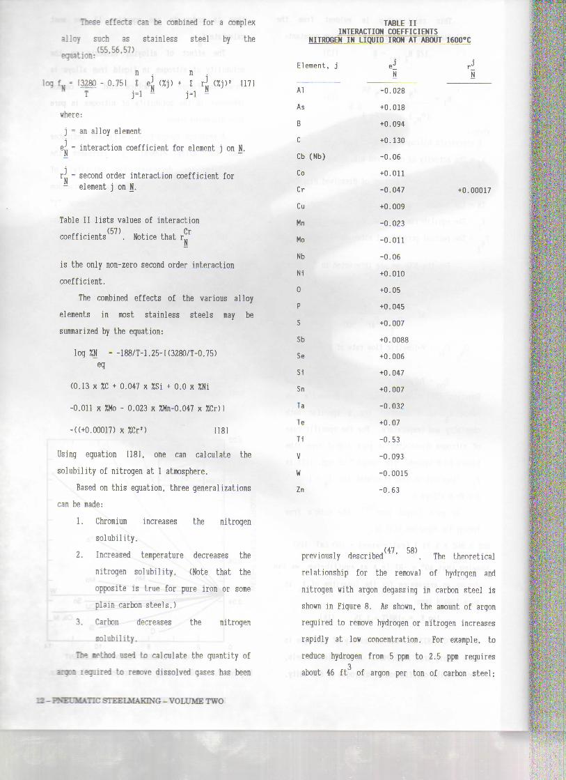
These effects can be combined for a complex
alloy such as stainless steel by the,. (55,56.57)equation:
TABLE IIINTERACTION COEFFICIENTS
n nlog fu = (3280 - 0.75) E ei (%j) + E ri (%j)' 1171
"T " j-i j-i
where;
j = an alloy element
K = interaction coefficient for element j on N.
r:; = second order interaction coefficient forelement j on N.
Table II lists values of interaction
coefficients . Notice that r±í
is the only non-zero second order interaction
coefficient.
The combined effects of the various alloy
elements in most stainless steels may be
summarized by the equation:
log %N = -188/M.25-K3280/T-0.75)eq
(0.13 x %C + 0.047 x %Si + 0.0 x %Ni
-0.011 x %Mo - 0.023 x %Mn-0.047 x %Cr)l
-((+0.00017) x %Cr2) 1181
Using equation 1181, one can calculate the
solubility of nitrogen at l atmosphere.
Based on this equation, three general izations
can be made:
1. Chromium increases the nitrogen
solubility.
2. Increased temperature decreases the
nitrogen solubility. (Note that the
opposite is true for puré iron or some
plain carbon steels.)
3. Carbon decreases the nitrogen
solubility.
The irthod used to calculate the quantity of
anjM isguired to re«ove dissolved gases hás been
NITROGEN IN LIQUID IRON AT ABOUT 1600°C
Element, j
Al
As
B
C
Cb (Nb)
Co
Cr
Cu
Mn
Mo
Nb
Ni
0
P
S
Sb
Se
Si
Sn
Ta
Te
Ti
V
W
Zn
ej rJN N
-0.028
+0.018
+0.094
+0.130
-0.06
+0.011
-0.047 +0.00017
+0.009
-0.023
-0.011
-0.06
+0.010
+0.05
+0.045
+0.007
+0.0088
+0.006
+0.047
+0.007
-0.032
+0.07
-0.53
-0.093
-0.0015
-0.63
previously described ' . The theoretical
relationship for the remova] of hydrogen and
nitrogen with argon degassing in carbon steel is
shown in Figure 8. AP shown, the amount of argon
required to remove hydrogen or nitrogen increases
rapidly at low concentration. For example, to
reduce hydrogen from 5 ppm to 2.5 ppm requires3
about 46 f t of argon per ton of carbon steel;
. - T ^ : - . 7 _ STEELUAKING-VOLDlfBTWO

12 r
10
UJaotrO 6
a.o.
20 60 100 140 180
ARGON SCF/TON
220 260
-l 120
100
80
60
40
20
10
CDOcr
Figure 8. Argon requirement for hydrogen andnitrogen removal at 2912°F. (Houstonand Cnath (58))
however, to go from 3 ppm to 1.5 ppm would require3
about 72 ft of argon per ton of steel. During
decarburization, the significant quantities of CO
evolved act as an inert gás with respect to
hydrogen and nitrogen and reduce the amount of
argon required to remove any given amount of these
gases. It is also possible to oalculate the
amount of inert gases needed to purqe nitrogen
from stainless steel. For example, to purge
dissolved nitrogen from a levei of 0.12% to 0.06%,
more than 100 ncf of argon/ton of stainless steel
is required (assuming 100% efficiency).(59,60,61,62,63)Several investigators of the
kinetics of nitrogen absorption and desorption
have indicated that the presence of surface active
elements, oxygen and sulfur, serves as a barrier
to nitrogen transfer. It is generall y accepted
that oxygen (or sulfur) will occupy a najority of
the surface sites on the gás metal interface
preventing the rapid transfer of nitrogen (or
other eleients) across the interface.
Consequently, it is necessary to assume a purqing
efficiency based on knowledge of the actual
conditions in the bath. The proper use of these
conceçts results in accurate control of nitroqen
content in AOD refined steels.
D. Mechanism
While it is beyond the scope of this book to
review the mechanism and modeling of
decarburization in the AOD process in detail, it
is appropriate to make some general comments. The
basic reaction model of the AOD process is that
oxygen injected through the tuyeres reacts
primarily with dissolved carbon, silicon, chromium
and manganese in the tuyere zone. The carbon
monoxide and the argon (or nitrogen) which was
injected with the oxygen as the diluent gás forms
a bubble which carries the other oxides through
the bath as it ascends. The metallie oxides
formed are reduced by carbon and silicon dissolved
in the bath as these oxides rise with the bubbles
through the melt. Any oxide not reduced while the
bubble is in the bath is transferred to the slag
phase once the ascending bubble reaches the top of
the bath.
Simultaneously, while the gás bubbles ascend,
nitrogen, if it is the diluent gás, is absorbed
into the melt. Conversely, if argon is the
diluent gás, dissolved nitrogen in the rnelt is
desorbed into the bubble. The rates of the
nitrogen reaction depends on the lass transfer of
nitrogen in the melt and are influenced by the
concentration of surface active elements in the
bath such as sulfur and oxygen.
At high carbon leveis, the rate of
decarburization is deternined by the mass transfer
of oxygen. At low carbon leveis (generally below
0.12% in refining austenitic stainless steels),
and at conventional oxygen/argon ratio and flow
rates, the decarburization rate is controlled by
the mass transfer of carbon in the bath to the
bubbles.A general understanding of this mechanism,
coupled with the fundamentais of dilution, mixing
and degassing discussed previously, provides the
reader with a sense of why the AOD process hás
proven só successful for stainless steel refining.
Y-
r
PNEUMATIC STEELMAKING - VOLUME TWO - 13