


Languages
Pages
Legal


Chapter 4
OrthographicWriting

TOPICS
Views selection
Orthographic writing steps
Alignment of views
Tangency and intersections
Basic dimensioning

View Selection

VIEW SELECTION STEPS
1. Orient the object to the best position
relative to a glass box.
2. Select the front view.
3. Select adjacent views.

STEP 1 : Orient the Object
The object should be placed in its natural position.
NO !
The object should presents its features in actual
size and shape in orthographic views.
GOOD
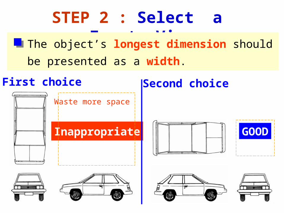
STEP 2 : Select a Front View
The object’s longest dimension should be
presented as a width.
Inappropriate
First choice
GOOD
Second choice
Waste more space

Inappropriate
The adjacent views that are projected from the
selected front view should appear in its natural
position.
STEP 2 : Select a Front View
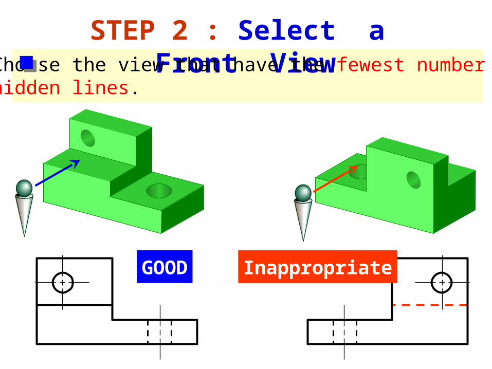
STEP 2 : Select a Front ViewChoose the view that have the fewest number ofhidden lines.
GOOD Inappropriate

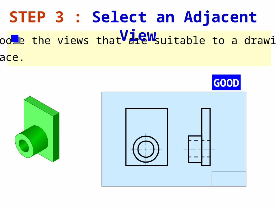
STEP 3 : Select an Adjacent View
GOOD
Inappropriate
Inappropriate
GOOD
Choose the view that have the fewest number ofhidden lines.

Choose the minimum number of views that can represent the major features of the object.
STEP 3 : Select an Adjacent View
Necessary
Necessary
Hole’s location can be specified on the same view.
Difficult to interprete.
Easy to understand

Choose the views that are suitable to a drawing
space.
STEP 3 : Select an Adjacent View
POOR
Not enough spacefor dimensioning.
Choose the views that are suitable to a drawing
space.
STEP 3 : Select an Adjacent View
GOOD

Example : View selection
Shape description
Size description
F.V.
W D
W
H
D mislead to…
F.V. & T.V. Three views F.V. & R.S.V.
H
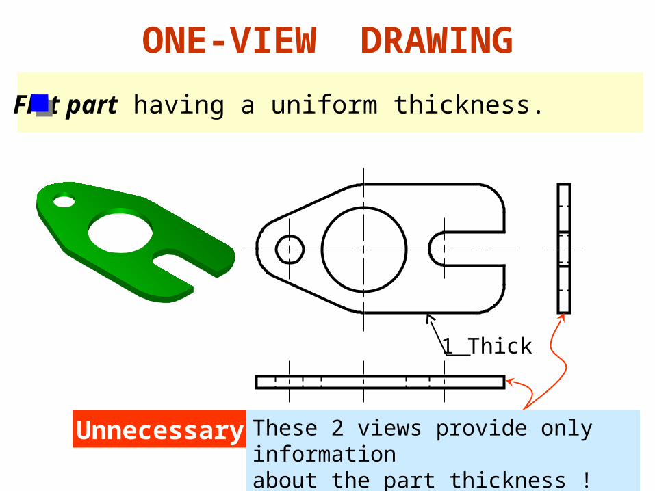
ONE-VIEW DRAWING
Flat part having a uniform thickness.
Unnecessary These 2 views provide only informationabout the part thickness !
1 Thick

ONE-VIEW DRAWING
Cylindrical-shaped part.
Unnecessary
Repeat !
Infer from CL
Unnecessary

TWO-VIEW DRAWING
There exists an identical view.
Repeat !
Unnecessary

The 3rd view has no significant contours of the object.
TWO-VIEW DRAWING
Unnecessary

TWO-VIEW DRAWING
Unnecessary
The 3rd view has no significant contours of the object.

Alignment of Views
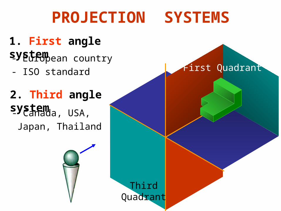
PROJECTION SYSTEMS
1. First angle system
2. Third angle system
First Quadrant
ThirdQuadrant
- European country
- ISO standard
- Canada, USA,
Japan, Thailand
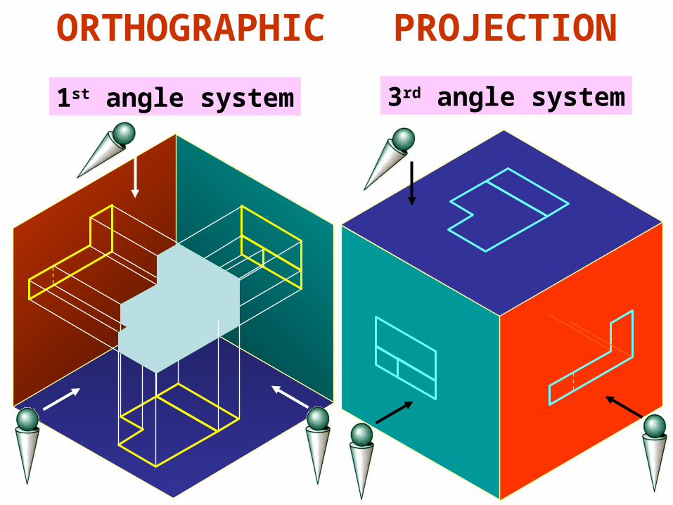
ORTHOGRAPHIC PROJECTION
1st angle system 3rd angle system

ORTHOGRAPHIC VIEWS
1st angle system 3rd angle system
Foldingline
Foldingline
Foldingline
Foldingline

ORTHOGRAPHIC VIEWS
1st angle system 3rd angle system
Front View
Front View
Right Side View
Right Side View
Top View
Top View

First angle system Third angle system
PROJECTION SYMBOLS

PROJECTION SYMBOLS
d 1.7d
2.2d
Suggested proportion

Orthographic Writing Steps

WRITING STEPS
1. Select the necessary views
2. Layout the views.
3. Project the views.
4. Dimension the views.

1. SELECT THE NECESSARY VIEWS

45
152
152
64
2. LAYOUT THE VIEWS
A4
25
Choose anappropriate scale
1:1

PROJECT THE VIEWS
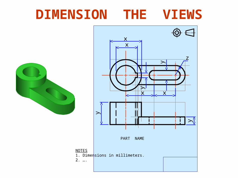
DIMENSION THE VIEWS
NOTES1. Dimensions in millimeters.2. ….
PART NAME
xx
x x
y
y
y
y
z
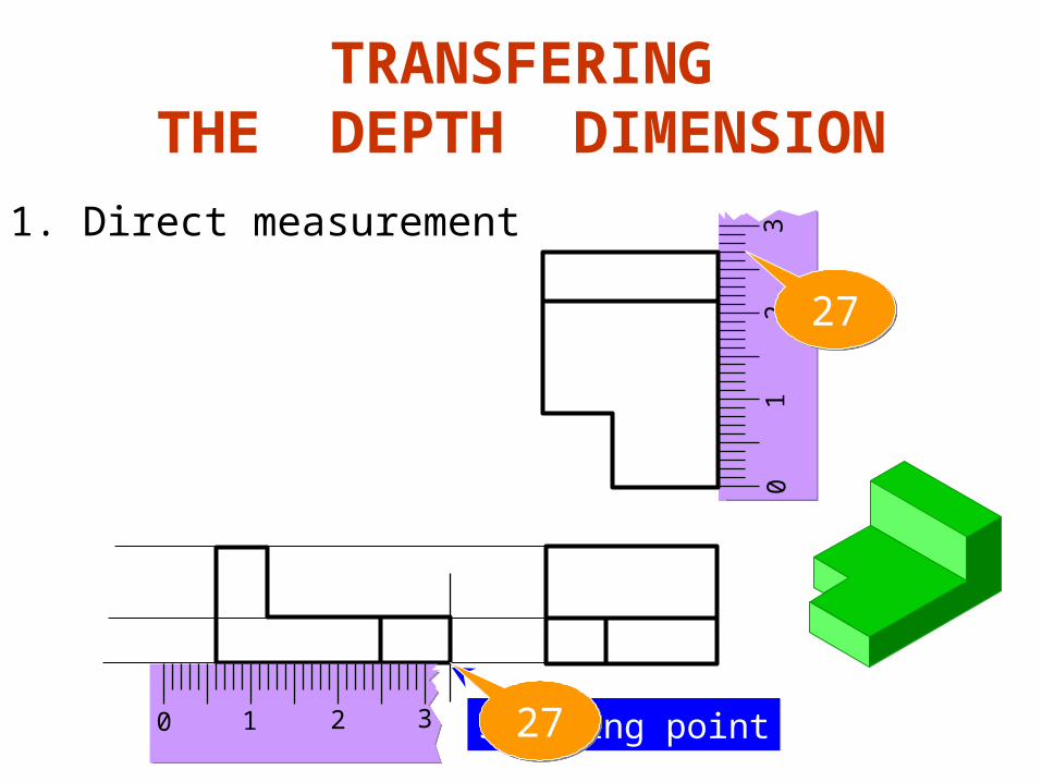
TRANSFERINGTHE DEPTH DIMENSION
1. Direct measurement
01
23
27
0 1 2 3 Starting point27

TRANSFERINGTHE DEPTH DIMENSION
2. Use miter line
45
Views too close

Basic Dimensioning

1. Extension lines
2. Dimension lines
3. Leader lines
4. Dimension numbers
5. Local notes
COMPONENTS
10 27
43
10 Drill, 2 HolesR16
17

Tangencies and Intersections

No line is formed when curved surface tangent
to a plane surface.
No line
No line
TANGENT & INTERSECTION
Line is formed when curved surface intersects
a plane surface.
tangent
tangent
intersect
intersect
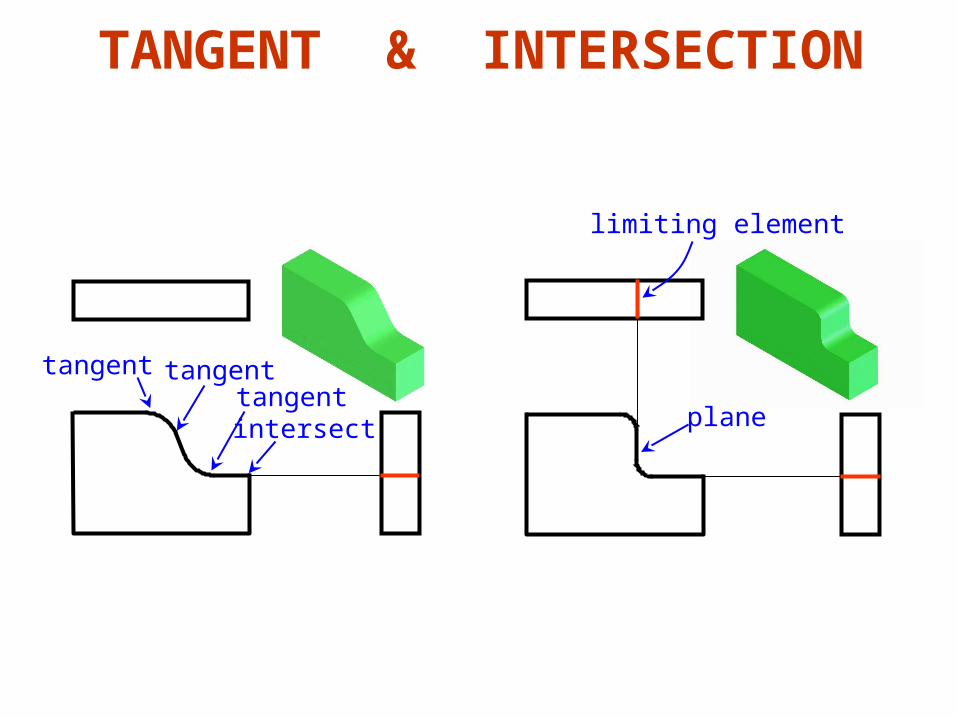
TANGENT & INTERSECTION
intersect
tangenttangent
tangent
plane
limiting element

TANGENT & INTERSECTION
intersect
No line
tangent
tangent
tangent
tangent
tangent
No line
tangentNo line
Top Related