


Languages
Pages
Legal

CEU
205
Compressed Air Systems
Continuing Education from the American Society of Plumbing Engineers
November 2013
ASPE.ORG/ReadLearnEarn
Air is the natural atmosphere surrounding Earth and is a major source of power possessing many advantages for industrial and commercial applications. It is nonflammable, economical, easily transmitted, and adaptable. Compressed air has thousands of applications. It is used for hand tools, air hammers, paving breakers, rock drills, positive-displacement pumps, paint chippers, vibrators, and more. It also is employed to actuate linear movement through a piston and cylinder or a diaphragm for air-actuated valves, doors, dampers, brakes, etc. Atomizing, spraying, and mov-ing hard-to-pump fluids are other applications. Compressed air can be bubbled to measure fluid levels, agitate liquids, and inhibit ice formation in bodies of water. Another use of compressed air is for instrumentation. Air circuits solve the most complex problems in automatic control, starting and stopping, and modulation of valves, machines, and processes. Some applications would be almost impossible with any power medium other than compressed air.
This chapter discusses compressed air for industrial and commercial applications. For medical compressed air used in healthcare facilities, refer to Chapter 2: “Plumbing Design for Healthcare Facilities.” For purified compressed air used in laboratories, refer to Chapter 12: “Laboratory Gases.”
For the purposes of this chapter, a compressed gas is any gas at a pressure higher than atmospheric.
CODES AND STANDARDS The building codes and standards impacting the design and installation of compressed air systems have been put in place to protect the safety and health of operating personnel and building occupants. However, no mandated code require-ments have been written specifically about compressed gases. Industry standards and guidelines are published by the Compressed Gas Association (CGA) and National Fire Protection Association (NFPA). These requirements are usu-ally specific to the type of facility, application, and end user.
FUNDAMENTALSAir is a fluid. The two types of fluids are liquids and gases. Gases have a weaker cohesive force holding their molecules together than liquids and will conform to the shape of their container. Ambient air is a mixture of gases, the main com-ponents of which are oxygen and nitrogen, along with many other gases in minor concentrations. For the composition of dry air, refer to Table 9-1.
The actual volume of an atom of gas in relation to the total volume of a gas molecule is quite small; thus, gases are mostly empty space. Pressure is produced when the
molecules of a gas in an enclosed space rapidly strike the enclosing surfaces. If the gas is confined to smaller and smaller spaces, the molecules strike the container walls more and more frequently, producing greater pressure.
Because free air is less dense at higher elevations, a cor-rection factor (see Table 9-2) must be used to determine the equivalent volume of air at high elevations. Temperature is also a consideration. Because a volume of free air at a high temperature exerts a higher pressure than the same volume of air at a lower temperature, a correction factor (see Table 9-3) must be used to determine the equivalent volume of air at different temperatures.
The most commonly used compression process in indus-trial compressed air production is the polytropic process, which allows variations in pressure, temperature, and volume to occur during the compression cycle.
UNITS OF MEASUREPressurePressure measurements are made using force acting upon an area. In the United States, pressure is commonly measured using inch-pound (IP) units of measurement and expressed as pounds per square inch (psi). Another common unit of measurement for low-pressure systems is inches of water column (in. wc). In International System (SI) units, pressure is commonly measured in kilopascals (kPa).
The two basic reference points for measuring pressure are standard atmospheric pressure and a perfect vacuum. When pressure is measured using standard atmospheric pressure as the point of reference, the measurement is called gauge pressure, expressed as pounds per square inch gauge (psig) (kPa). If the reference pressure level is a perfect vacuum, the term used is absolute pressure, expressed as pounds per square inch absolute (psia) (kPa absolute). A graphical rep-resentation of the relationship between gauge and absolute
Reprinted from Plumbing Engineering Design Handbook, Volume 3. © 2011, American Society of Plumbing Engineers.
Note: In determining your answers to the CE questions, use only the material presented in the corresponding continuing education article. Using information from other materials may result in a wrong answer.
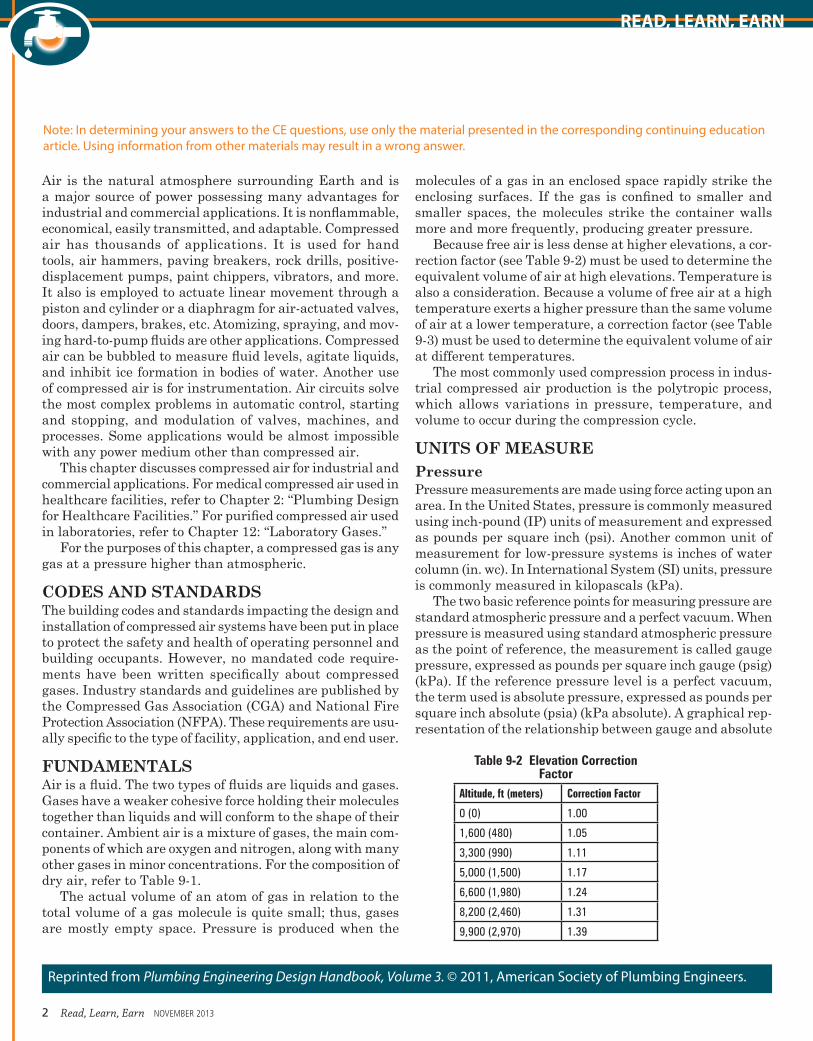
Table 9-2 Elevation Correction Factor
Altitude, ft (meters) Correction Factor
0 (0) 1.00
1,600 (480) 1.05
3,300 (990) 1.11
5,000 (1,500) 1.17
6,600 (1,980) 1.24
8,200 (2,460) 1.31
9,900 (2,970) 1.39
2 Read, Learn, Earn NOVEMBER 2013
READ, LEARN, EARN
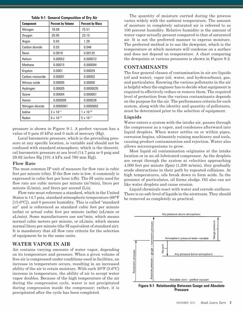
pressure is shown in Figure 9-1. A perfect vacuum has a value of 0 psia (0 kPa) and 0 inch of mercury (Hg).
Local barometric pressure, which is the prevailing pres-sure at any specific location, is variable and should not be confused with standard atmosphere, which is the theoreti-cal barometric pressure at sea level (14.7 psia or 0 psig and 29.92 inches Hg [101.4 kPa and 760 mm Hg]).
Flow RateThe most common IP unit of measure for flow rate is cubic feet per minute (cfm). If the flow rate is low, it commonly is expressed in cubic feet per hour (cfh). The SI units used for flow rate are cubic meters per minute (m3/min), liters per minute (L/min), and liters per second (L/s).
Flow rate must reference a standard, which in the United States is 14.7 psia, standard atmospheric temperature (60°F [15.6°C]), and 0 percent humidity. This is called “standard air” and is referenced as standard cubic feet per minute (scfm) or actual cubic feet per minute (acfm) (nL/min or aL/min). Some manufacturers use nm3/min, which means normal cubic meters per minute, or nL/min, which means normal liters per minute (the SI equivalent of standard air). It is mandatory that all flow rate criteria for the selection of equipment be in the same units.
WATER VAPOR IN AIRAir contains varying amounts of water vapor, depending on its temperature and pressure. When a given volume of free air is compressed under conditions used in facilities, an increase in temperature occurs, resulting in an increased ability of the air to retain moisture. With each 20°F (5.6°C) increase in temperature, the ability of air to accept water vapor doubles. Because of the high temperature of the air during the compression cycle, water is not precipitated during compression inside the compressor; rather, it is precipitated after the cycle has been completed.
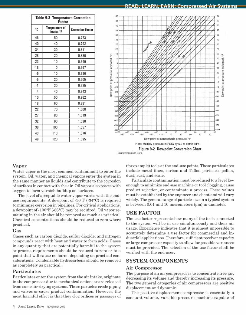
The quantity of moisture carried during the process varies widely with the ambient temperature. The amount of moisture in completely saturated air is referred to as 100 percent humidity. Relative humidity is the amount of water vapor actually present compared to that of saturated air. It is not the preferred manner to express moisture. The preferred method is to use the dewpoint, which is the temperature at which moisture will condense on a surface and does not depend on temperature. A chart comparing the dewpoints at various pressures is shown in Figure 9-2.
CONTAMINANTSThe four general classes of contamination in air are liquids (oil and water), vapor (oil, water, and hydrocarbons), gas, and particulates. Knowing the various pollutants in the air is helpful when the engineer has to decide what equipment is required to effectively reduce or remove them. The required level of protection from the various contaminants depends on the purpose for the air. The performance criteria for each system, along with the identity and quantity of pollutants, must be determined prior to the selection of equipment.
Liquids Water enters a system with the intake air, passes through the compressor as a vapor, and condenses afterward into liquid droplets. When water settles on or within pipes, corrosion begins, ultimately ruining machinery and tools, causing product contamination and rejection. Water also allows microorganisms to grow.
Most liquid oil contamination originates at the intake location or in an oil-lubricated compressor. As the droplets are swept through the system at velocities approaching 4,000 feet per minute (fpm) (1,200 m/min), they gradually erode obstructions in their path by repeated collisions. At high temperatures, oils break down to form acids. In the presence of particulates, oil forms sludge. Oil also can act like water droplets and cause erosion.
Liquid chemicals react with water and corrode surfaces. There is no safe level of liquids in the airstream. They should be removed as completely as practical.
Table 9-1 General Composition of Dry AirComponent Percent by Volume Percent by Mass
Nitrogen 78.09 75.51
Oxygen 20.95 23.15
Argon 0.93 1.28
Carbon dioxide 0.03 0.046
Neon 0.0018 0.00125
Helium 0.00052 0.000072
Methane 0.00015 0.000094
Krypton 0.0001 0.00029
Carbon monoxide 0.00001 0.00002
Nitrous oxide 0.00005 0.00008
Hydrogen 0.00005 0.0000035
Ozone 0.00004 0.000007
Xenon 0.000008 0.000036
Nitrogen dioxide 0.0000001 0.0000002
Iodine 2 x 10-11 1 x 10⁻¹⁰
Radon 6 x 10-18 5 x 10-17
Figure 9-1 Relationship Between Gauge and Absolute Pressure
NOVEMBER 2013 Read, Learn, Earn 3
(for example) tools at the end-use points. These particulates include metal fines, carbon and Teflon particles, pollen, dust, rust, and scale.
Particulate contamination must be reduced to a level low enough to minimize end-use machine or tool clogging, cause product rejection, or contaminate a process. These values must be established by the engineer and client and will vary widely. The general range of particle size in a typical system is between 0.01 and 10 micrometers (μm) in diameter.
USE FACTORThe use factor represents how many of the tools connected to the system will be in use simultaneously and their air usage. Experience indicates that it is almost impossible to accurately determine a use factor for commercial and in-dustrial applications. Therefore, sufficient receiver capacity or large compressor capacity to allow for possible variances must be provided. The selection of the use factor shall be verified with the end user.
SYSTEM COMPONENTS Air Compressor The purpose of an air compressor is to concentrate free air, decreasing its volume and thereby increasing its pressure. The two general categories of air compressors are positive displacement and dynamic.
The positive-displacement compressor is essentially a constant-volume, variable-pressure machine capable of
Vapor Water vapor is the most common contaminant to enter the system. Oil, water, and chemical vapors enter the system in the same manner as liquids and contribute to the corrosion of surfaces in contact with the air. Oil vapor also reacts with oxygen to form varnish buildup on surfaces.
The level of acceptable water vapor varies with the end-use requirements. A dewpoint of -30°F (-34°C) is required to minimize corrosion in pipelines. For critical applications, a dewpoint of -100°F (-86°C) may be required. Oil vapor re-maining in the air should be removed as much as practical. Chemical concentrations should be reduced to zero where practical.
Gas Gases such as carbon dioxide, sulfur dioxide, and nitrogen compounds react with heat and water to form acids. Gases in any quantity that are potentially harmful to the system or process requirements should be reduced to zero or to a point that will cause no harm, depending on practical con-siderations. Condensable hydrocarbons should be removed as completely as practical.
Particulates Particulates enter the system from the air intake, originate in the compressor due to mechanical action, or are released from some air-drying systems. These particles erode piping and valves or cause product contamination. However, the most harmful effect is that they clog orifices or passages of
Table 9-3 Temperature Correction Factor
°C Temperature of Intake, °F Correction Factor
-46 -50 0.773
-40 -40 0.792
-34 -30 0.811
-28 -20 0.830
-23 -10 0.849
-18 0 0.867
-9 10 0.886
-5 20 0.905
-1 30 0.925
4 40 0.943
10 50 0.962
18 60 0.981
22 70 1.000
27 80 1.019
32 90 1.038
38 100 1.057
43 110 1.076
49 120 1.095
Figure 9-2 Dewpoint Conversion ChartSource: Hankison Corp.
4 Read, Learn, Earn NOVEMBER 2013
READ, LEARN, EARN: Compressed Air Systems
operating over a wide range of discharge pressures at a relatively constant capacity. Positive-displacement compres-sors can be further categorized as reciprocating or rotary machines. Typical reciprocating compressors include piston and diaphragm types. Rotary compressors include such types as sliding vane, liquid ring (or liquid piston), and screw. The most widely used types of dynamic compressors include the centrifugal and the axial flow.
Dynamic compressor characteristics are opposite those of the positive-displacement compressor. This machine oper-ates over a relatively wide range of capacities at a relatively constant discharge pressure.Reciprocating CompressorA reciprocating compressor uses positive displacement, which is accomplished by a piston moving in a cylinder similar to an internal combustion engine. When compres-sion occurs on only one stroke, it is called a single-acting cylinder, and when compression occurs on both strokes, it is called a double-acting compressor. The cylinders can be horizontal, vertical, or angled, and they can be sealed and lubricated with oil when traces of oil in the discharge air are not problematic. Oil-free machines are also available, but they cost more than those requiring oil.
Cooling is accomplished by air or water. Water cooling is generally more effective than air cooling and consumes less power, but the initial and operating costs are higher. A two-stage compressor consumes less power than a single-stage unit for the equivalent output.Sliding Vane Compressor Sliding vane compressors work by utilizing vanes that are mounted eccentrically in a cylindrical rotor and are free to slide in and out of slots. As the rotor turns, the space between the compressor casing and the vanes decreases, compressing the air.
These are compact units, well suited for direct connection to a relatively high-speed motor. Their efficiency is usually less than that of an equivalent piston unit. They are best applied in situations where small, low-capacity compressors,
generally in the range of 100 cfm and 75 psi (2,832 L/min and 517.1 kPa), are required.Liquid Ring Compressor Liquid ring compressors, sometimes referred to as liquid pistons, are rotary positive-displacement units that use a fixed-blade rotor in an elliptical casing. The casing is partially filled with liquid. As the rotor turns, the blades set the liquid in motion. As they rotate, the blades extend deeper into the liquid ring, compressing the trapped air. The resulting air is completely oil free.
This type of compressor also can handle wet, corrosive, or explosive gases. Various liquids, which are compatible with specific gases to be compressed, can be used.
This unit is very well suited for hospital and laboratory use. A practical limitation of 100 psi (689.5 kPa) exists, and they consume more power than piston units of a similar rating.Straight Lobe Compressor Straight lobe (often referred to as rotary lobe) compressors function in a manner similar to that of gear pumps. A pair of identical rotors, each with lobes shaped like the figure 8 in cross section, are mounted inside a casing. As they rotate, air is trapped between the impeller lobes and pump casing and carried around without compression. This air is then discharged, using the existing pressure in the system to increase pressure. These units are available oil free and generally are recommended for pressures up to 200 psig (1,379 kPa) and 150 scfm (4,285 nL/min).Rotary Screw Compressor Rotary screw compressors use a pair of close-clearance, helical-lobe rotors turning in unison. As air enters the inlet, the rotation of the rotors causes the cavity in which air is trapped to become smaller and smaller, increasing pressure. The air reaches the end of the screw at high pressure and flows out smoothly at the discharge port.
The majority of rotary screw compressors in use today are of the oil-flooded type, but designs that produce oil-free air are available. These compressors produce pulse-free air
Table 9-4 Standard ASME Receiver Dimensions
Diameter, in. Length, ft Volume, ft3
13 4 4.5
14 6 11
24 6 19
30 7 34
36 8 57
42 10 96
48 12 151
54 14 223
60 16 314
66 18 428Notes: 1 in. = 25.4 mm; 1 ft = 0.003 m3; 1 ft = 0.3 m
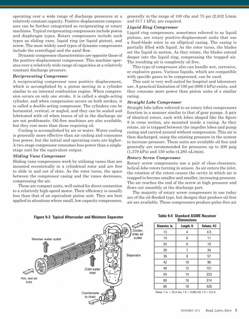
Figure 9-3 Typical Aftercooler and Moisture Separator
NOVEMBER 2013 Read, Learn, Earn 5
and are generally available for pressures from 150 to 300 psi (1,034 to 2,068 kPa) and 300 scfm (8,496 nL/min).Centrifugal Compressor Centrifugal compressors are dynamic machines that utilize impellers to add kinetic energy to the airstream by centrifu-gal action. The velocity of the air is increased as it passes through each impeller. A diffuser section decelerates the high-velocity air, converting the kinetic energy into poten-tial energy. The volute further increases the pressure and directs the air into the discharge piping.
Centrifugal compressors typically produce large volumes of air at relatively low pressures. Higher pressures can be attained by adding stages with intercooling between the stages. The centrifugal compressor takes up less floor space but requires more power than a reciprocating unit of equal output. Its inherently oil-free air delivery is a major advantage in many applications.
PipingThe most often used pipe material is ASTM B88 copper tube for water use. When considering other materials, the engineer should take into account the pressure rating of the pipe and joints, the temperature rating of the pipe, and the joining method. If all elements are equal, the least expensive piping shall be selected.
The allowable pressure ratings for the various piping materials is based on wall thickness values at ambient temperatures calculated from equations appearing in ASME B31.3: Process Piping Design. The pipe pressure rating is se-lected to resist the highest system design pressure, which is usually in the range of 50–55 psi (344.7–379.2 kPa). Higher pressures for special uses are well within the limits of piping with flared and brazed joints. Type L copper tubing is used for pressures up to 200 psi (1,379 kPa), and type K is used for pressures up to 300 psi (2,068.4 kPa).
Joints The most often used joint for copper tubing at low pressures is the soldered joint, with those at 100 psig (689.5 kPa) and above being brazed. The flared joint is popular because it
can be made using only a saw and some wrenches. When copper tubing is used with flared joints, the pipe shall not have embossed identification stamped into the pipe because doing so causes leaks at the joint. There is no designation for patented flared joints, but they are acceptable for all applications as long as the allowable joint pressure ratings are not exceeded.
Experience has shown that reaming the ends of pipe or tubing to obtain a smooth interior has left pieces of shaved metal in the pipe. If this is a cause for concern, reaming methods and tools are available to eliminate this problem.
For systems with operating pressures up to 200 psi (1,379 kPa) and piping 4 inches (101.6 mm) and smaller, consider 304 or 316 stainless steel and/or copper tubing with press-fit joining.
ValvesValves are an often-overlooked component of a compressed air system, but the valve type and material are important to efficiency and operating life. The valves used should have been designed for compressed air service. Be careful to examine valve specifications for airway ports or openings smaller than the nominal size indicated or expected.
The most often used shutoff valves are ball valves. Three-piece valves also are desirable because the body can be separated from the end connections when being installed and serviced. For exact control and modulating purposes, needle valves are used because of the precise level of control permitted.
In addition to the end use, the engineer should take the following design considerations into account when select-ing valves.
• The most important valve feature is minimum flow restriction (pressure drop) when the valve is fully open. Ball, gate, and plug valves have the lowest pressure drop, and it is extremely rare to use these types for flow restriction.
• The pressure rating should be suitable for the maximum pressure possible.
Table 9-5 Selection of Supply Hose SizeAir Inlet Port NPT, in.
8 ¼ a ½
Supply Hose Size ID, in.
¼ a ½ ¾
Table 9-6 Inlet Air Filter CharacteristicsFilter Type Filtration
Efficiency, %Particle Size,
µmMaximum Drop
When Clean, wcComments (see key)
Dry 1009998
1053
3–8 (1)
Viscous impingement (oil wetted)
1009585
2010
¼–2 (2) (3)
Oil bath 9890
103
6–10 = nominal2 = low drop (2) (3) (4)
Dry with silencer 1009998
1053
5(5)7(6)
(1) Recommended for nonlubricated compressors and for rotary vane compressors in a high-dust environment(2) Not recommended for dusty areas or for nonlubricated compressors(3) Performance requires that oil is suitable for both warm and cold weather operation(4) Recommended for rotary vane compressors in normal service(5) Full flow capacity up to 1,600 scfm(6) Full flow capacity from 1,600 to 6,500 scfm
6 Read, Learn, Earn NOVEMBER 2013
READ, LEARN, EARN: Compressed Air Systems
• The valve body and seat materials must be compatible with the expected trace gases and contaminants.
• The valve must be capable of positive shutoff. • Leakage through the valve stem should be prevented.
Flow Meters Flow meters can be either of two types: electric or mechani-cal. The mechanical kind is called a variable-area type and uses a small ball as an indicator in a variable-area vertical tube. The type of mechanical meter most often used has an accuracy of 10 percent full scale. This means that if the flow range is from 1 to 10 scfm, the accuracy is ±1 acfm. More accurate variable-area flow meters are available.
The mass flow meters are electronically operated, using the difference in temperature that gas creates when flowing over a heated element. The mass flow meter is very accurate, but expensive.
Compressed Air ReceiversThe primary purpose of a receiver is to store air. Secondary purposes are to equalize pressure variations (pulsations) from the compressor and to collect residual condensate. Determination of the need for a receiver is always based on the type of pressure regulation the system uses. If the compressor runs 100 percent of the time and has constant pressure and blowoff, an air receiver is not required.
For most applications, the system pressure is regulated by starting and stopping the compressor, with a receiver used to store air and prevent the compressor from cycling too often. The generally accepted practice for reciprocating compressors is to limit starts to about 10 per hour (less is better) and the running time to 70 percent. Centrifugal, screw, and sliding vane compressors are best run 100 per-cent of the time, but the starts still should be limited to about 10 starts per hour.
Receivers should be ASME stamped for unfired pres-sure vessels. Manufacturers offer standard receiver sizes measured in gallons (liters) of water capacity (see Table 9-4). Receivers should be selected based on system demand and compressor size, using the starts per hour and running time best suited for the project. The design engineer must keep in mind that a compressor operates to satisfy the pres-sure switch rather than the use of air and that the receiver is an integral part of the system that must function with
respect to load conditions, amount of storage, and pressure differential. Often the manufacturer offers a standard size receiver for specific compressor models, but a commonly used formula to estimate the size of the receiver is as follows:
Equation 9-1
T = V×(P1−P2)C+Pa
where:T = Time the receiver takes to go from the upper to the
lower pressure limit, minutesV = Volume of the tank, cubic feet (m3)P1 = Maximum tank pressure, psia (kPa)P2 = Minimum tank absolute pressure, psia (nL/min)C = Free air needed, scfm (nL/min)Pa = Atmospheric pressure, psia (kPa)
While it is common practice to locate a receiver near the compressor, the designer should consider locating the receiver at the largest air consumers. Installation of a receiver at a remote point on the piping system allows the system to handle surges and possibly can eliminate the need for an additional compressor.
Piping connections should be made in such a way that the incoming air is forced to circulate and mix with the air already inside the tank before being discharged. A common piping scheme used in large manufacturing facilities is to provide a loop header around the plant. This scheme pro-vides flexibility for future connections and reduced pressure drops to remote locations. Oversizing the header one pipe size also provides storage capacity and may eliminate the need for a remote receiver.
An automatic drain valve is required so the receiver can discharge wastewater to an adjacent floor drain through an air gap.
Aftercoolers An aftercooler is used to lower the temperature of the com-pressed air immediately after the compression process. Air leaving the compressor is very hot, and it is desirable to reduce the temperature of discharged air to the range of 70–110°F (21.1–43°C). A primary reason the temperature is lowered is to remove moisture that would otherwise condense elsewhere in the system as the air cools to ambi-ent conditions. Therefore, it is considered good practice to
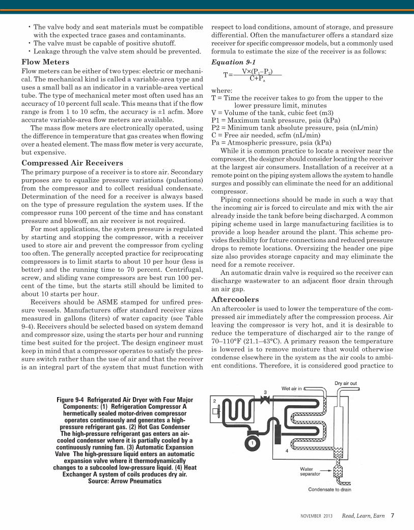
Figure 9-4 Refrigerated Air Dryer with Four Major Components: (1) Refrigeration Compressor A hermetically sealed motor-driven compressor operates continuously and generates a high-
pressure refrigerant gas. (2) Hot Gas Condenser The high-pressure refrigerant gas enters an air-
cooled condenser where it is partially cooled by a continuously running fan. (3) Automatic Expansion Valve The high-pressure liquid enters an automatic
expansion valve where it thermodynamically changes to a subcooled low-pressure liquid. (4) Heat
Exchanger A system of coils produces dry air.Source: Arrow Pneumatics
NOVEMBER 2013 Read, Learn, Earn 7
install the cooling unit as close to the compressor discharge as practical. An aftercooler is also useful to precondition air where additional conditioning is necessary.
The three general types of aftercoolers are water cooled, air cooled, and refrigerant. Air-cooled is the most often used type of aftercooler.
Since large amounts of water typically are removed from the air in an aftercooler, a moisture separator is usually provided. The separator could be either an integral part of the aftercooler or a separate unit. Additional factors to be considered when selecting an aftercooler are pressure drop through the unit, space and clearance requirements, opera-tion costs, and maintenance.
SeparatorsA separator is a type of filter used to remove large quanti-ties of liquid water or oil from the airstream. Often, oil and water form an emulsion inside the compressor and are discharged together.
Since suspended liquids are present after air leaves the aftercooler or compressor, the compressor discharge is the most common location for a separator. The general design of these units should allow for the removal of between 90 and 99 percent, by weight, of liquids. An aftercooler and separator are illustrated in Figure 9-3.
Compressed Air DryersAir dryers are used to remove additional water vapor from the airstream after the separator has removed large volumes of water consisting of large droplets. The general categories of dryer, defined by the method of drying, are high pres-surization of the compressed air, refrigerated, absorption, desiccant (adsorption), and heat of compression.
High Pressurization High pressurization reduces the quantity of water vapor by compressing air to pressures greater than those required for actual use. An increase in pressure decreases the ability of air to hold moisture. Since pressurization requires large amounts of energy, this process is rarely used.Refrigerated DryerThe most common type of dryer uses a refrigerant and is called a refrigerated dryer. It lowers the temperature of the airstream through a heat exchanger to produce a lower dewpoint. Lowering the dewpoint reduces the capability of the air to retain moisture. Moisture then condenses out of the air onto the coils of the dryer, and a moisture separator removes the condensate.
The cooling medium in the coil could be water, brine, or a refrigerant. A refrigerated dryer requires operation within a small range of pressure and airflow rates to be effective. In general, a minimum of 20 percent of rated airflow is required to achieve the specified moisture removal.
The greatest limitation of these dryers is that they cannot practically produce a pressure dewpoint lower than 35°F (1.7°C). Otherwise, the condensed moisture would freeze on the coils. The advantages are that they have a low operating cost and do not introduce impurities into the airstream. A refrigerated air dryer is illustrated in Figure 9-4.Absorption Absorption dryers use either a solid or a liquid medium and operate on the principle that when the airstream containing water vapor passes through or over a deliquescent material, the water causes the medium to change state (or dissolve). The solvent is then drained away; thus, the water is re-moved, and the amount of material available for absorption
Table 9-7 Recommended Air Inlet Pipe Size
Maximum scfm Free Air
Capacity
Minimum Size, in.
50 2½
110 3
210 4
400 5
800 6Note: 1 cfm = 0.03 m3/minSource: James Church
Table 9-8 Equivalent Pressure Loss Through Valves and Fittings, ft of pipe
Nominal Pipe Size,
in.
Actual ID, in.
Gate Valve
Long Radius, All or on Run of Standard Tee
Standard Ell or on Run of Tee Reduced
in Size 50 Percent
Angle Valve
Close Return Bend
Tee Through
Side Outlet
Globe Valve
½ 0.622 0.36 0.62 1.55 8.65 3.47 3.10 17.3
¾ 0.824 0.48 0.82 2.06 11.4 4.60 4.12 22.9
1 1.049 0.61 1.05 2.62 14.6 5.82 5.24 29.1
1¼ 1.380 0.81 1.38 3.45 19.1 7.66 6.90 38.3
1½ 1.610 0.94 1.61 4.02 22.4 8.95 8.04 44.7
2 2.067 1.21 2.07 5.17 28.7 11.5 10.3 57.4
2½ 2.469 1.44 2.47 6.16 34.3 13.7 12.3 68.5
3 3.068 1.79 3.07 6.16 42.6 17.1 15.3 85.2
4 4.026 2.35 4.03 7.67 56.0 22.4 20.2 112.0
5 5.047 2.94 5.05 10.1 70.0 28.0 25.2 140.0
6 6.065 3.54 6.07 15.2 84.1 33.8 30.4 168.0
8 7.981 4.65 7.96 20.0 111.0 44.6 40.0 222.0
10 10.020 5.85 10.00 25.0 139.0 55.7 50.0 278.0
12 11.940 6.96 11.00 29.8 166.0 66.3 59.6 332.0Notes: 1 ft = 0.3 m; 1 in. = 25.4 mm
8 Read, Learn, Earn NOVEMBER 2013
READ, LEARN, EARN: Compressed Air Systems
is reduced. Solid absorbers are much more common than liquid ones.
The advantage of this type of dryer is that it requires no outside power source or connection to any other system. A disadvantage is that impurities may be introduced into the airstream.Desiccant DryersDesiccant dryers use a porous, nonconsumable material that causes water vapor to condense as a very thin film on the material’s surface, a process called adsorption. This material is called a desiccant. No chemical interaction oc-curs, and the adsorption process is reversible. Desiccant dryers are capable of producing pressure dewpoints as low as -100°F (-73.3°C).
Desiccant materials include silica gel, activated alumina, and aluminosilicate (molecular sieve). Each material also has applications for the removal of specific impurities other than water. Desiccant materials age when in use over a period of years, which may affect their capacity. In addition, care must be taken to avoid contamination of the materials, particularly by oils.
The method of regeneration is the primary way to dis-tinguish between types of desiccant dryers. One type is the duplex-bed pressure swing (heatless) dryer, which uses approximately 15 percent of the hot air directly discharged from the compressor before it goes into the aftercooler to dry one bed while the other is operating. Additional com-pressor capacity is necessary to provide this extra air. The other type is the heat-activated dryer, which uses internal or external heaters.
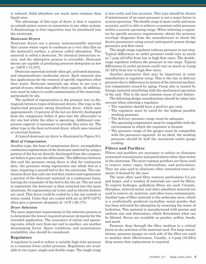
A typical desiccant air dryer is illustrated in Figure 9-5.Heat of CompressionAnother type, the heat of compression dryer, accomplishes continuous regeneration of the desiccant material by using a portion of the hot air directly discharged from the compres-sor before it goes into the aftercooler. The difference between this and the pressure swing dryer is that for continuous duty, the pressure swing regenerates one whole bed at a time, requiring a second bed to dry the airstream. The con-tinuous dryer has only one bed that rotates and regenerates a portion of the desiccant material on a continuous basis, leaving the remainder of the bed to dry the air. The air used to regenerate the desiccant is then returned into the main airstream. No regeneration air is lost, and no electric heaters are used. This dryer could be cooled by a fan (air cooled) or water cooled. Units that are cooled with air at 95°F (35°C) often give a pressure dewpoint of -15°F (-26.1°C).Dryer SelectionThe most important requirement in the selection process is to determine the lowest required pressure dewpoint for the intended application. The economics of initial and operat-ing costs, which vary from one unit to another, are another determining factor. Space conditions and maintenance availability also should be considered.
RegulatorsA regulator is used to reduce a variable high inlet pressure to a constant lower outlet pressure. Regulators are avail-able in two types: single and double stage. The single stage
is less costly and less accurate. This type should be chosen if maintenance of an exact pressure is not a major factor in system operation. The double stage is more costly and more accurate, and it is able to achieve a constant outlet pressure within a narrow operating range. When selecting a regula-tor for specific accuracy requirements, obtain the accuracy envelope diagrams from the manufacturer to check the device parameters using actual anticipated system design pressures and flow rates.
The single-stage regulator reduces pressure in one step. Typical differences in outlet pressure could vary as much as 7 psig (49 kPa) from low to high flow rates. The double-stage regulator reduces the pressure in two steps. Typical differences in outlet pressure could vary as much as 3 psig (21 kPa) from low to high flow rates.
Another parameter that may be important in some installations is regulator creep. This is the rise in delivery pressure due to differences in motion of the internal mechan-ical components caused by aging. Creep also is caused by foreign material interfering with the mechanical operation of the unit. This is the most common cause of unit failure.
The following design considerations should be taken into account when selecting a regulator.
• The regulator should have a positive gas vent. • The regulator must be rated for the highest possible
working pressure. • The delivery pressure range must be adequate. • The operating temperature must be compatible with the
environment in which the regulator is located. • The pressure range of the gauges must be compatible
with the pressures expected. As an ideal, the working pressure should be half the maximum outlet gauge reading.
Filters and Purifiers Filters and purifiers are necessary to reduce or eliminate unwanted contaminants and particulates other than water in the airstream. The most common purifiers are those used to remove water vapor, hydrocarbons, and particulates. They are also used to eliminate other unwanted trace ele-ments if desired by the user.
The most often used filter removes particulates 0.2 μm and larger, and a number of materials are used for filters. To remove hydrogen, palladium filters are used. Ceramic, fiberglass, sintered metal, and other adsorbent material are used to remove oil, moisture, and other trace contaminants. Another type of filter material is the molecular sieve, which is a synthetically produced crystalline metal powder that has been activated for adsorption by removing the water of hydration. This material is manufactured with precise and uniform size and dimensions, which determines what can be filtered. Sieves are available as powder, pellets, beads, and mesh.
Pressure drop through the filter medium is a critical factor in the selection of the material used. For large instal-lations, pressure gauges on each side of the filter are used to monitor their effectiveness. Usually, a 5-psig (35-kPa) drop means that replacement is required.
NOVEMBER 2013 Read, Learn, Earn 9
Relief Valves Relief valves are used to protect a system from overpressure. A relief valve must be provided between the regulator and the first shutoff valve in the system, at the first point in the system that could be subject to full cylinder pressure if the regulator should fail. The discharge should be independently piped outdoors, and the discharge pipe should be a minimum of ¾ inch in diameter. No valve should be located between the relief valve and the regulator, and no connection from any source to a relief discharge may be made from any other system. The relief valve release point should be set to 50 percent more than working pressure.
When two-stage regulators are used, a preset first-stage (or interstage) relief valve is sometimes required to protect the second stage from overpressure. Additionally, it is good practice to install an adjustable relief valve on the second stage to protect the system and instruments from damage due to excessive pressure. For outdoor installations involv-ing inert gases, the relief valves can exhaust directly to atmosphere. For indoor installations, or any installation involving toxic or flammable gases, the relief valve exhaust should be captured and vented to a safe location.
Hose and FittingsMost tools use flexible hose to connect to the piping system, and the hose used is usually larger than the air inlet port on the tool it serves. Table 9-5 indicates generally accepted practice for the selection of supply hose based on the size of the inlet port. When the length of the hose extends more than 20 feet (6 m), one size larger should be used to allow for the additional friction loss. It is good practice to limit the friction loss within the hose to approximately 5 psig (35 kPa). (Refer to Table 9-11 for pressure loss through various sizes and lengths of hose.)
Alarms Alarms are necessary to alert users of immediate or po-tential trouble, and they can be visible and/or audible. The typical alarms are high system pressure, low system pres-
sure, and reserve in use. In some installations, a normal light is also requested. If a single cylinder is the sole source of supply, an alarm might be installed when the pressure in the tank reaches 400 psig (2,800 kPa). Other alarms could be provided to indicate high pressure loss at filters, low gas temperature, purifiers at limit of capacity, and flow limit valve operation.
These alarms typically are installed in an alarm panel. The panel could be mounted in a constantly occupied loca-tion such as a maintenance shop or receptionist area or in the area of use itself, depending on the availability and level of maintenance.
Various devices must be placed in the system for these alarms to function, such as pressure switches, transducers, and auxiliary contacts in a manifold assembly to transmit the alarm signal to the alarm panel.
Vibration IsolationVibration isolation is achieved by the proper selection of resilient devices between the pump base and the building structure. This isolation is accomplished by placing isolators between the pump and the floor, flexible connections on all piping from the compressor, and spring-type hangers on the piping around the compressor for a distance of about 20 ft (6 m). Earthquake loads should be acquired and applied to system piping as required.
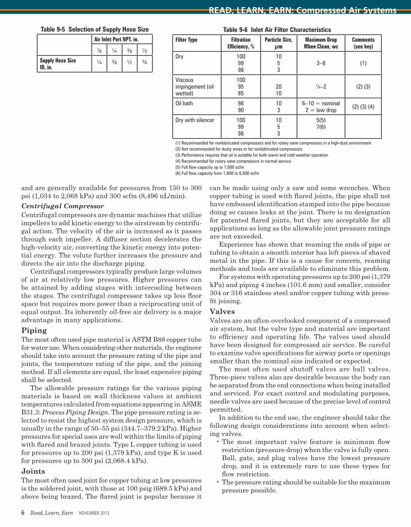
Compressor Inlet PipingSince air compressor performance depends on inlet condi-tions, the inlet piping system deserves special care and should be held to the minimum requirements. The air intake should provide a supply of air to the compressor that is as clean, cool, and dry as possible. Depending on location, an inlet filter may be required. Table 9-6 provides the characteristics of inlet air filters. The velocity of the inlet air should be limited to about 1,000 fpm (300 m/min) The proposed location should be studied for the presence of any type of airborne contamination and positioned to avoid the probability of contaminated intake. For recommended intake piping sizes, refer to Table 9-7.
PIPE LAYOUT DESIGN AND SIZINGOn the piping layout, the following information must be available:
• A list of all air-consuming devices and their locations• Minimum and maximum pressure requirements for
each device • Actual volume of air used by each device • Suggested duty cycle and diversity factor for equipment• Special individual air purification requirements• An allowance for future expansion
Recommended Pipe and System Sizing Following is a recommended system sizing procedure. (Note: The sizing procedure discussed below is not intended for compressed air for laboratories.)
1. Locate the mechanical room and lay out the locations of compressors and ancillary equipment.
2. Establish a general layout of the system from the stor-age area to the farthest outlet or use point. Measure
Figure 9-5 Absorption (Dessicant) DryerSource: Van Air Systems
10 Read, Learn, Earn NOVEMBER 2013
READ, LEARN, EARN: Compressed Air Systems
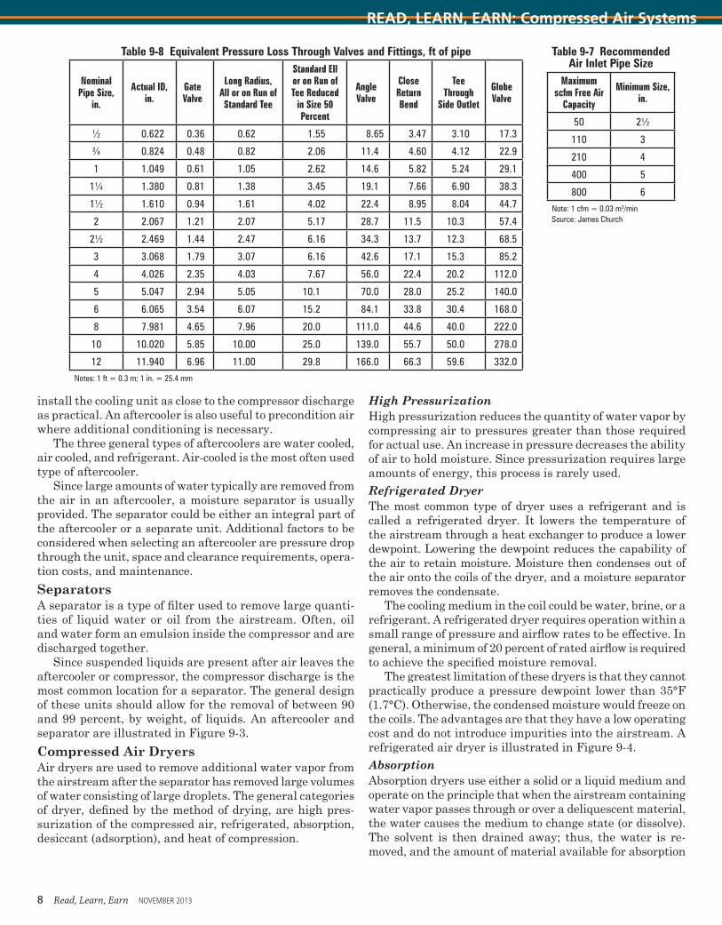
the actual distance along the run of pipe to the most remote outlet. Next, add a fitting allowance. For ease of calculations, the addition of 30 percent to the actual measured run will give a conservative approximation of the entire system. Adding the measured length to the fitting allowance will result in the equivalent run of pipe. If a precise calculation is desired, refer to Table 9-8 for the equivalent loss of pressure, in feet, through valves and fittings.
3. Obtain specific purity requirements from the end user and choose all of the filters, purifiers, and acces-sories necessary for system purity. This will establish a combined allowable pressure drop through each of them and the assembly as a whole.
4. Establish the actual pressure required at the far-thest outlet.
5. Calculate the allowable total system friction loss.a. It is accepted practice for general use to have a mini-
mum system pressure loss of 10 percent in the pipe. For high-pressure systems serving specific equip-ment or tools, start with the high end of the range for the actual pressure required. Thus, for a 125-psig (860-kPa) system, a figure of ±12 psig (85 kPa) fric-tion loss will be allowed. This figure is variable. To that figure add the pressure required to overcome the drop through the ancillary purifier equipment and other accessories as required.
b. Divide the total equivalent run of pipe (in hundreds of feet) by the allowable friction loss to calculate the allowable friction loss per 100 feet of pipe. This calculation is necessary to allow the use of the sizing chart provided in this chapter. If other methods are used to indicate friction loss in the piping system, calculate the loss in that specific method.
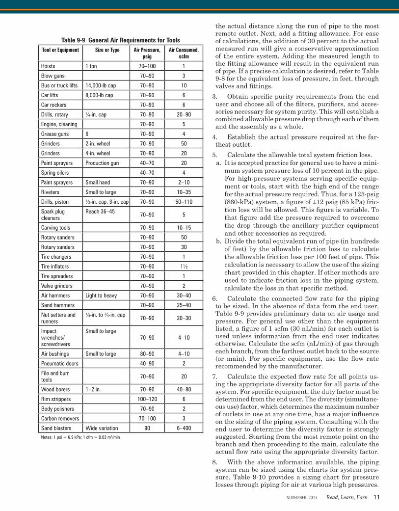
6. Calculate the connected flow rate for the piping to be sized. In the absence of data from the end user, Table 9-9 provides preliminary data on air usage and pressure. For general use other than the equipment listed, a figure of 1 scfm (30 nL/min) for each outlet is used unless information from the end user indicates otherwise. Calculate the scfm (nL/min) of gas through each branch, from the farthest outlet back to the source (or main). For specific equipment, use the flow rate recommended by the manufacturer.
7. Calculate the expected flow rate for all points us-ing the appropriate diversity factor for all parts of the system. For specific equipment, the duty factor must be determined from the end user. The diversity (simultane-ous use) factor, which determines the maximum number of outlets in use at any one time, has a major influence on the sizing of the piping system. Consulting with the end user to determine the diversity factor is strongly suggested. Starting from the most remote point on the branch and then proceeding to the main, calculate the actual flow rate using the appropriate diversity factor.
8. With the above information available, the piping system can be sized using the charts for system pres-sure. Table 9-10 provides a sizing chart for pressure losses through piping for air at various high pressures.
Table 9-9 General Air Requirements for ToolsTool or Equipment Size or Type Air Pressure,
psigAir Consumed,
scfm
Hoists 1 ton 70–100 1
Blow guns 70–90 3
Bus or truck lifts 14,000-lb cap 70–90 10
Car lifts 8,000-lb cap 70–90 6
Car rockers 70–90 6
Drills, rotary ¼-in. cap 70–90 20–90
Engine, cleaning 70–90 5
Grease guns 6 70–90 4
Grinders 2-in. wheel 70–90 50
Grinders 4-in. wheel 70–90 20
Paint sprayers Production gun 40–70 20
Spring oilers 40–70 4
Paint sprayers Small hand 70–90 2–10
Riveters Small to large 70–90 10–35
Drills, piston ½-in. cap, 3-in. cap 70–90 50–110
Spark plug cleaners
Reach 36–45 70–90 5
Carving tools 70–90 10–15
Rotary sanders 70–90 50
Rotary sanders 70–90 30
Tire changers 70–90 1
Tire inflators 70–90 1½
Tire spreaders 70–90 1
Valve grinders 70–90 2
Air hammers Light to heavy 70–90 30–40
Sand hammers 70–90 25–40
Nut setters and runners
¼-in. to ¾-in. cap 70–90 20–30
Impact wrenches/screwdrivers
Small to large70–90 4–10
Air bushings Small to large 80–90 4–10
Pneumatic doors 40–90 2
File and burr tools 70–90 20
Wood borers 1–2 in. 70–90 40–80
Rim strippers 100–120 6
Body polishers 70–90 2
Carbon removers 70–100 3
Sand blasters Wide variation 90 6–400Notes: 1 psi = 6.9 kPa; 1 cfm = 0.03 m3/min
NOVEMBER 2013 Read, Learn, Earn 11
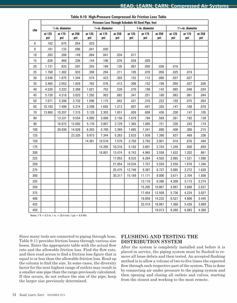
Since many tools are connected to piping through hose, Table 9-11 provides friction losses through various size hoses. Enter the appropriate table with the actual flow rate and the allowable friction loss. Find the flow rate, and then read across to find a friction loss figure that is equal to or less than the allowable friction loss. Read up the column to find the size. In some cases, the diversity factor for the next highest range of outlets may result in a smaller-size pipe than the range previously calculated. If this occurs, do not reduce the size of the pipe; keep the larger size previously determined.
FLUSHING AND TESTING THE DISTRIBUTION SYSTEM After the system is completely installed and before it is placed in service, the piping system must be flushed to re-move all loose debris and then tested. An accepted flushing method is to allow a volume of two to five times the expected flow through each respective part of the system. This is done by connecting air under pressure to the piping system and then opening and closing all outlets and valves, starting from the closest and working to the most remote.
Table 9-10 High-Pressure Compressed Air Friction Loss Table
cfm
Pressure Loss Through Schedule 40 Steel Pipe, feet
½-in. diameter ¾-in. diameter 1-in. diameter 1¼-in. diameter
at 125 psi
at 175 psi
at 250 psi
at 125 psi
at 175 psi
at 250 psi
at 125 psi
at 175 psi
at 250 psi
at 125 psi
at 175 psi
at 250 psi
6 .102 .075 .054 .023
8 .181 .133 .096 .041 .030
10 .283 .208 .149 .064 .047 .034 .017
15 .636 .469 .336 .144 .106 .076 .038 .028
20 1.131 .833 .597 .255 .188 .135 .067 .050 .036 .016
25 1.768 1.302 .933 .399 .294 .211 .105 .078 .056 .025 .019
30 2.546 1.875 1.344 .574 .423 .303 .152 .112 .080 .037 .027
35 3.465 2.552 1.829 .782 .576 .413 .206 .152 .109 .050 .037 .026
40 4.526 3.333 2.388 1.021 .752 .539 .270 .199 .142 .065 .048 .034
45 5.728 4.218 3.023 1.292 .952 .682 .341 .251 .180 .083 .061 .044
50 7.071 5.208 3.732 1.596 1.175 .842 .421 .310 .222 .102 .075 .054
60 10.183 7.499 5.374 2.298 1.692 1.213 .607 .447 .320 .147 .108 .078
70 13.860 10.207 7.315 3.128 2.303 1.651 .826 .608 .436 .200 .147 .105
80 13.331 9.554 4.085 3.008 2.156 1.079 .794 .569 .261 .192 .138
90 16.872 12.092 5.170 3.807 2.729 1.365 1.005 .721 .330 .243 .174
100 20.830 14.928 6.383 4.700 3.369 1.685 1.241 .890 .408 .300 .215
125 23.325 9.973 7.344 5.263 2.633 1.939 1.390 .637 .469 .336
150 14.361 10.576 7.579 3.792 2.793 2.001 .918 .676 .494
175 14.395 10.316 5.162 3.801 2.724 1.249 .920 .659
200 18.801 13.474 6.742 4.965 3.558 1.632 1.202 .861
225 17.053 8.533 6.284 4.503 2.065 1.521 1.090
250 21.054 10.534 7.757 5.559 2.550 1.878 1.346
275 25.475 12.746 9.387 6.727 3.085 2.272 1.628
300 30.317 15.169 11.171 8.006 3.671 2.704 1.938
325 13.110 9.396 4.309 3.173 2.274
350 15.205 10.867 4.997 3.680 2.637
375 17.454 12.509 5.736 4.224 3.027
400 19.859 14.232 6.527 4.806 3.445
425 22.419 16.067 7.368 5.426 3.889
450 18.013 8.260 6.083 4.360Notes: 1 ft = 0.3 m; 1 in. = 25.4 mm; 1 psi = 6.9 kPa
12 Read, Learn, Earn NOVEMBER 2013
READ, LEARN, EARN: Compressed Air Systems
Testing is done by pressurizing the system to the test pressure with air. The system test pressure for low-pressure systems is 150 percent more than the working pressure. For systems with a working pressure up to 200 psig, the entire piping system is tested to 300 psig for one hour, with no leakage permitted. If a working pressure higher than 200 psig is required, the system is tested at 150 percent of the system pressure. This pressure testing should be done in increments of 100 psig, starting with 100 psig. This is done to avoid damage due to a catastrophic failure. Leaks are repaired after each increment. After final testing, it is recommended that the piping be left pressurized at the system working pressure.
GLOSSARYAbsolute pressure The arithmetic sum of gauge and
atmospheric/barometric pressures. It must be used in all calculations involving the basic gas laws.
Absolute temperature The temperature of a body referred to as absolute zero, at which point the volume of an ideal gas theoretically becomes zero. On the Fahrenheit scale, this is -459.67°F; on the Celsius scale, it is -273.15°C. Engineering values of -460°F and -273°C are typically used.
Aftercooling The cooling of air in a heat exchanger following the completion of compression to reduce the tem-perature and to liquefy condensable vapors
Altitude The elevation of a compressor above sea levelBarometric pressure The absolute atmospheric pres-
sure existing at the surface of Earth. It is the weight of a unit column of air above the point of measurement. It var-ies with altitude and, at any given location, with moisture content and weather.
Capacity The quantity of air actually delivered when op-erating between the specified inlet and discharge pressures. For ejectors, capacity is measured in pounds per hour. For all other compressor types, capacity is a volume measured at the conditions of pressure, temperature, gas composition, and moisture content existing at the compressor inlet flange.
Compressed air Ambient air stored and distributed at a pressure greater than atmospheric pressure (14.7 psia, 101 kPa)
Compressibility The property of air or of an air mixture that causes it to differ in volume from that of a perfect gas when each is under the same pressure and temperature conditions. Occasionally it is called deviation. It must be experimentally determined.
Compression efficiency The ratio of the theoretical work requirement (using a stated process) to the actual work required to be done on the air for compression and delivery. Expressed as a percentage, compression efficiency accounts for leakage and fluid friction losses and thermodynamic variations from the theoretical process.
Compression ratio The ratio of the absolute discharge to the absolute intake pressure. It usually applies to a single stage of compression, but may be applied to a complete mul-tistage compressor as well.
Critical pressure The saturation pressure at the critical temperature. It is the highest vapor pressure that a liquid
can exert. When calculated for a mixture, it is called the pseudo (pretend) critical condition.
Critical temperature The highest temperature at which a gas can be liquefied.
Dead-end pressure The suction pressure attained by an ejector or positive-displacement vacuum pump at zero capacity with the suction absolutely blanked off.
Degrees Kelvin (°K) An absolute temperature scaleDegree Rankine (°R) An absolute temperature scaleDensity The weight of a given volume of gas, usually
expressed in pounds per cubic feet at standard pressure and temperature conditions (air = 0.09 pound/cubic foot [1.3 kilograms/cubic meter])
Design (built-in) compression ratio In a rotary compressor, the compression ratio that has been attained when the fixed discharge port is uncovered. A helical-lobe compressor (and most other rotary units) can have an op-erating ratio somewhat higher or lower than the design ratio with little change in efficiency.
Dewpoint The temperature at which the vapor in a space (at a given pressure) will start to condense (form dew). The dewpoint of a gas mixture is the temperature at which the highest boiling point constituent will start to condense.
Discharge pressure The total pressure (static plus velocity) at the discharge flange of the compressor. Velocity pressure usually is considered only with dynamic compres-sors.
Discharge temperature The temperature existing at the discharge flange of the compressor
Displacement The net volume swept by the moving parts in a unit of time, usually one minute (applies only to positive displacement compressors)
Dry bulb temperature The ambient gas temperatureDry gas Any gas or gas mixture that contains no water
vapor and/or in which all of the constituents are substan-tially above their respective saturated vapor pressures at the existing temperature (see wet gas). Note: In commercial compressor work, a gas may be considered dry (even though it contains water vapor) if its dewpoint is low at the inlet condition (-50° to -60°F).
Dry unit One in which there is no liquid injection and/or liquid circulation for evaporative cooling or sealing (see evaporative cooling)
Energy The capacity of a substance, either latent or ap-parent, to exert a force through a distance, that is, to do work
External energy The energy represented by the product of pressure and volume. It may be regarded as the energy a substance possesses by virtue of the space it occupies.
Internal energy The energy a substance possesses because of the motion and configuration of its atoms, mol-ecules, and subatomic particles.
Kinetic energy The energy a substance possesses by virtue of its motion or velocity. It enters into dynamic and ejector compressor calculations, but seldom into positive-displacement problems.
Potential energy The energy a substance possesses because of its elevation above Earth (or above some other chosen datum plane)
NOVEMBER 2013 Read, Learn, Earn 13
Enthalpy (heat content) The sum of the internal and external energies
Entrainment ratios Used with ejectors to convert the weight of gas and/or water vapor handled to or from equiva-lent air. They are based on extensive tests.
Entropy A measure of the unavailability of energy in a substance
Equivalent air An ejector term—the calculated pounds per hour of air at 70°F and 14.696 psia and containing normal atmospheric moisture that is equivalent to, but not necessarily equal to, the weight rate of the gas handled by the ejector at suction conditions. Entrainment ratios are involved.
Evaporative cooling Takes place when a liquid (usu-ally water) is injected into the gas stream before or during compression. As compression takes place, the gas tempera-ture rises and some or all of the liquid is evaporated—the latent heat of liquid vaporization being removed from the gas—thus lowering its temperature.
Fixed compression ratio The design (built-in) com-pression ratio for a rotary unit having this feature
Free air Air at ambient conditions at a specific location. Temperature, barometric pressure, and moisture content may be different from those of standard air. The term “free air” is not to be used unless the ambient temperature, humidity, and barometric pressure conditions at the compressor loca-tion are stated.
Gauge pressure Pressure as determined by most instru-ments and gauges. Barometric pressure must be allowed for to obtain the true or absolute pressure.
Heat Energy transferred because of a temperature dif-ference. No transfer of mass occurs.
Horsepower A unit of work equal to 33,000 foot-pounds per minute
Brake horsepower The total power input required in-cluding gas horsepower plus all friction losses
Gas horsepower The actual work required to compress and deliver a given gas quantity, including all thermody-namic, leakage, and fluid friction losses. It does not include mechanical losses.
Indicated horsepower That obtained by indicator card analysis of compression or expansion in a cylinder of a re-ciprocating compressor. It is the same as gas horsepower.
Peak horsepower The maximum power required by a given compressor when operating at a constant discharge pressure with variable intake pressure or constant intake pressure with variable discharge pressure.
Theoretical horsepower The work theoretically re-quired to compress and deliver a given gas quantity in accordance with a specified product
Humidity In normal usage, the moisture (water vapor) in the atmosphere
Relative humidity The ratio of the actual partial vapor pressure in an air and vapor mixture to the saturated vapor pressure at the existing dry-bulb mixture temperature, usu-ally expressed in percent
Specific humidity The ratio of the weight of water vapor in an air and vapor mixture to the weight of dry air, usually expressed as pounds of vapor per pound of dry air
Inlet pressure The total pressure (static plus velocity) at the inlet flange of the compressor. Velocity pressure is usually considered only with dynamic compressors.
Inlet temperature The temperature at the inlet flange of the compressor. Note: In a multistage compressor, the various stages may have differing inlet temperatures.
Intercooling The cooling of gas between stages of com-pression to reduce the temperature, reduce the volume to be compressed in the succeeding stage, liquefy condensable vapors, and save power
Maximum discharge pressure As applied to ejectors, the maximum absolute static recovery pressure against which the ejector will operate with stability
Mechanical efficiency The ratio, expressed in percent, of the indicated horsepower to the actual shaft horsepower (or steam indicated horsepower in an integral steam-driven unit)
Normal air The term used for average atmospheric air at sea level in a temperate zone where it contains some moisture. It is defined as being at 14.696 psia, 68°F, 36 percent relative humidity, and weighing 0.075 pound per cubic feet. The k-value is 1.395.
Piston displacement For a reciprocating compressor cylinder, the net volume displaced by the piston at rated machine speed, generally expressed in cubic feet per minute (cfm). For single-acting cylinders, it is the displacement of the compressing end only. For double-acting cylinders, it is the total of both ends. For multistage compressors, the displacement of the first stage only is commonly stated as that of the entire machine.
Precooler A heat exchanger located immediately pre-ceding an ejector to condense and remove a portion of the vapor in the mixture and thus reduce the total pounds per hour to be handled
Psychrometry A measurement of the properties of air and water vapor mixtures in the atmosphere
Pumping The reversal of flow within a dynamic com-pressor that takes place when the capacity being handled is reduced to a point where insufficient pressure is being generated to maintain flow
Ratio of specific heats The ratio of the specific heat at constant pressure to the specific heat constant volume. It may vary considerably with pressure and temperature.
Recovery pressure That pressure of either motive fluid or discharge at which an ejector requires stable operation following a period of unstable operation due to having previ-ously reached the breaking pressure.
Reduced pressure The ratio of the actual absolute gas pressure to the absolute critical pressure.
Reduced temperature The ratio in absolute units of the actual gas temperature to the critical temperature.
Saturation When a vapor is at the dewpoint or satura-tion temperature corresponding to its partial pressure. A gas is never saturated with a vapor. The space occupied jointly by the gas and vapor may be saturated, however.
Degree of saturation The ratio of the weight of a vapor existing in a given space to the weight that would be pres-ent if the space were saturated at the space temperature
14 Read, Learn, Earn NOVEMBER 2013
READ, LEARN, EARN: Compressed Air Systems
Saturated air and vapor mixture A mixture in which the space occupied by the mixture is saturated with water vapor at the mixture temperature
Saturated vapor pressure The pressure existing at a given temperature in a closed vessel containing a liquid and the vapor from that liquid after equilibrium conditions have been reached. It depends only on temperature and must be determined experimentally.
Saturation pressure Another term for saturated vapor pressure
Saturation temperature The temperature correspond-ing to a given saturated vapor pressure for a given vapor
Slip The internal leakage within a rotary compressor. It represents gas at least partially compressed but not deliv-ered. It is experimentally determined and expressed in cfm to be deducted from the displacement to obtain capacity.
Slip rpm The speed required of a rotary compressor to maintain a given discharge pressure, supplying leakage only (zero actual output). It is an experience factor.
Specific gravity The ratio of the density of a given gas to the density of dry air, both measured at the same specified conditions of temperature and pressure, usually 14.696 psia and 60°F. It should also take into account any compressibility deviation from a perfect gas.
Specific heat (heat capacity) The rate of change in enthalpy with temperature. It is commonly measured at constant pressure or at constant volume. The values are different and are known as cp and cv respectively.
Specific volume The volume of a given weight of gas, usually expressed as cubic feet per pound at standard pres-sure and temperature conditions
Standard air Dry air with a relative humidity of 0 percent, a temperature of 60°F (15.6°C), and a pressure of 14.7 psig (101.4 kPa). For the chemical industry, standard air is 68°F (20°C) at a relative humidity of 0 percent, and a pressure of 14.7 psig (101.4 kPa). Some manufacturers use a relative humidity of 36 percent, a temperature of 68°F (20°C), and a pressure of 14.2 psig (100 kPa) for per-formance test ratings. It is imperative that the conditions under which a compressor rating is calculated are obtained from the owner and manufacturer.
Actual cubic feet per minute (acfm) (actual liters per minute [aL/min]) A volume measurement of standard air after it has been compressed. The term “acfm (aL/min)” is not to be used unless the pressure is stated.
Standard cubic feet per minute (scfm) (normal li-ters per minute [nL/min]) A volume measurement of air at standard conditions. Outside the United States, standard is commonly referred to as normal, hence nL/min and nL/s.
Standard pressure and temperature (SPT) 14.696 psia and 60°F unless specifically stated otherwise
State A gas’s condition at an instant of time as described or measured by its properties
Suction pressure The absolute static pressure prevail-ing at the suction of the ejector
Superheated air and vapor mixture A mixture in which the space occupied by the mixture is above the satu-ration temperature at the mixture temperature
Temperature The property of a substance that gauges the potential or driving force for the flow of heat
Thermal compressor An ejector used to compress waste or exhaust steam or any other gas through a moderate range of compression above atmospheric pressure
Vapor pressure The pressure exerted by a vapor confined within a given space. The vapor may be the sole occupant, or the space or may be associated with other gases.
Wet bulb temperature Used in psychrometry, the temperature recorded by a thermometer whose bulb has been covered with a wetted wick and whirled on a sling psychrometer. Taken with the dry bulb, it permits the determination of the relative humidity of the atmosphere.
Wet gas Any gas or gas mixture in which one or more of the constituents is at its saturated vapor pressure. The constituent at saturation pressure may or may not be water vapor.
Wet helical-lobe unit A device that handles a small constant flow of liquid with the gas, utilizes evaporative (injection) cooling, or circulates a liquid for sealing and/or cooling. The last may or may not be evaporative cooling.
Work Energy in transition, defined in units of force times distance. Work cannot be done unless there is movement.
NOVEMBER 2013 Read, Learn, Earn 15
READ, LEARN, EARN: Compressed Air Systems
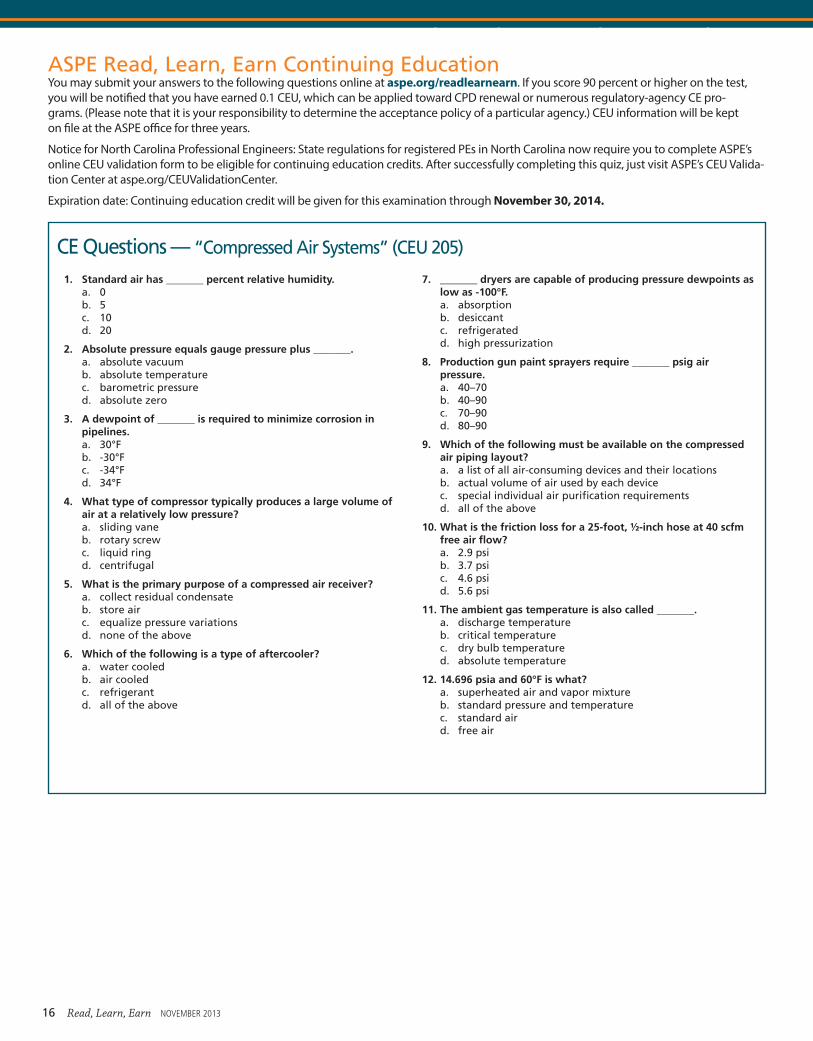
CE Questions — “Compressed Air Systems” (CEU 205)
1. Standard air has _______ percent relative humidity.a. 0b. 5c. 10d. 20
2. Absolute pressure equals gauge pressure plus _______.a. absolute vacuumb. absolute temperaturec. barometric pressured. absolute zero
3. A dewpoint of _______ is required to minimize corrosion in pipelines.a. 30°Fb. -30°Fc. -34°Fd. 34°F
4. What type of compressor typically produces a large volume of air at a relatively low pressure?a. sliding vaneb. rotary screwc. liquid ringd. centrifugal
5. What is the primary purpose of a compressed air receiver?a. collect residual condensateb. store airc. equalize pressure variationsd. none of the above
6. Which of the following is a type of aftercooler?a. water cooledb. air cooledc. refrigerantd. all of the above
7. _______ dryers are capable of producing pressure dewpoints as low as -100°F.a. absorptionb. desiccantc. refrigeratedd. high pressurization
8. Production gun paint sprayers require _______ psig air pressure.a. 40–70b. 40–90c. 70–90d. 80–90
9. Which of the following must be available on the compressed air piping layout?a. a list of all air-consuming devices and their locationsb. actual volume of air used by each devicec. special individual air purification requirementsd. all of the above
10. What is the friction loss for a 25-foot, ½-inch hose at 40 scfm free air flow?a. 2.9 psib. 3.7 psic. 4.6 psid. 5.6 psi
11. The ambient gas temperature is also called _______.a. discharge temperatureb. critical temperaturec. dry bulb temperatured. absolute temperature
12. 14.696 psia and 60°F is what?a. superheated air and vapor mixtureb. standard pressure and temperaturec. standard aird. free air
ASPE Read, Learn, Earn Continuing EducationYou may submit your answers to the following questions online at aspe.org/readlearnearn. If you score 90 percent or higher on the test, you will be notified that you have earned 0.1 CEU, which can be applied toward CPD renewal or numerous regulatory-agency CE pro-grams. (Please note that it is your responsibility to determine the acceptance policy of a particular agency.) CEU information will be kept on file at the ASPE office for three years.
Notice for North Carolina Professional Engineers: State regulations for registered PEs in North Carolina now require you to complete ASPE’s online CEU validation form to be eligible for continuing education credits. After successfully completing this quiz, just visit ASPE’s CEU Valida-tion Center at aspe.org/CEUValidationCenter.
Expiration date: Continuing education credit will be given for this examination through November 30, 2014.
16 Read, Learn, Earn NOVEMBER 2013