


Languages
Pages
Legal

)
ASSEMBLY INSTRUCTIONS
FOR
TURF TENDER WITH VARIABLE-RATE BOTTOM
HITCH ASSEMBLY
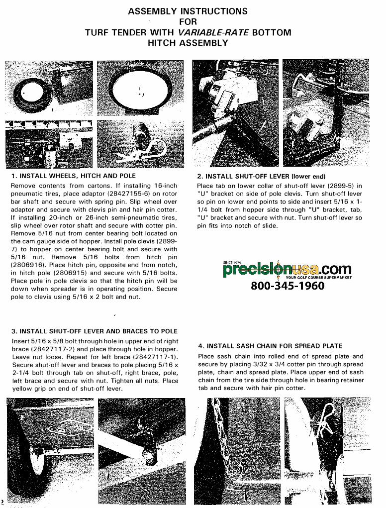
1. INSTALL WHEELS, HITCH AND POLE
Remove contents from cartons. If installing 16-inch
pneumatic tires, place adaptor (28427155-6) on rotor
bar shaft and secure with spring pin. Slip wheel over
adaptor and secure with clevis pin and hair pin cotter.
If installing 20-inch or 26-inch semi-pneumatic tires,
slip wheel over rotor shaft and secure with cotter pin.
Remove 5/16 nut from center bearing bolt located on
the cam gauge side of hopper. Install pole clevis (2899-
7) to hopper on center bearing bolt and secure with
5/16 nut. Remove 5/16 bolts from hitch pin
(2806916). Place hitch pin, opposite end from notch,
in hitch pole (2806915) and secure with 5/16 bolts.
Place pole in pole clevis so that the hitch pin will be
down when spreader is in operating position. Secure
pole to clevis using 5/16 x 2 bolt and nut.
3. INSTALL SHUT-OFF LEVER AND BRACES TO POLE
Insert 5/16 x 5/8 bolt through hole in upper end of right
brace (28427117-2) and place through hole in hopper.
Leave nut loose. Repeat for left brace (28427117-1).
Secure shut-off lever and braces to pole placing 5/16 x
2-1 /4 bolt through tab on shut-off, right brace, pole,
left brace and secure with nut. Tighten all nuts. Place
yellow grip on end of shut-off lever.
2. INST ALL SHUT-OFF LEVER (lower end)
Place tab on lower collar of shut-off lever (2899-5) in
"U" bracket on side of pole clevis. Turn shut-off lever
so pin on lower end points to side and insert 5/16 x 1-
1 /4 bolt from hopper side through "U" bracket, tab,
"U" bracket and secure with nut. Turn shut-off lever so
pin fits into notch of slide.
4. INSTALL SASH CHAIN FOR SPREAD PLATE
Place sash chain into rolled end of spread plate and
secure by placing 3/32 x 3/4 cotter pin through spread
plate, chain and spread plate. Place upper end of sash
chain from the tire side through hole in bearing retainer
tab and secure with hair pin cotter.
ASSEMBLY INSTRUCTIONS
FOR
TURF TENDER WITH VARIABLE-RATE BOTTOM
HANDLE ASSEMBLY
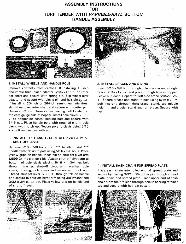
1 . INST ALL WHEELS AND HANDLE POLE
Remove contents from cartons. If installing 16-inch pneumatic tires, place adaptor (28427155-6) on rotor bar shaft and secure with spring pin. Slip wheel over adaptor and secure with clevis pin and hair pin cotter. If installing 20-inch or 26-inch semi-pnei.frnatic tires, slip wheel over rotor shaft and secure with cotter pin. Remove 5/16 nut from center bearing bolt located on the cam gauge side of hopper. Install pole clevis (2899-7) to hopper on center bearing bolt and secure with5/16 nut. Place handle pole with notched end in poleclevis with notch up. Secure pole to clevis using 5/16x 2 bolt and secure with nut.
3. INSTALL "T" HANDLE, SHUT-OFF PIVOT ARM &
SHUT-OFF LEVER
Remove 5/16 x 5/8 bolts from "T" handle. Install "T" handle with tab up to pole using,5/16 x 5/8 bolts. Place yellow grips on handle. Place pin on shut-off pivot arm (2899-3) into slot on slide. Attach shut-off pivot arm to bottom of pole clevis placing 5/16 x 1-3/4 hex bolt through washer, shut-off pivot arm, washer, pole clevis, bushing, pole clevis .and secure with lock nut. Thread shut-off lever (2899-4) through tab on handle and secure to shut-off pivot arm using 3/8 washer and 3/32 x 3/4 cotter pin. Place yellow grip on handle end of shut-off lever.
2. INSTALL BRACES AND STAND
Insert 5/16 x 5/8 bolt through hole in upper end of right brace (28427125-2) and place through hole in hopper. Leave nut loose. Repeat for left side brace (28427125-1). Secure braces and stand to pole using 5/16 x 2-1 /4 bolt inserting through right brace, stand, top middle hole in handle pole, stand and left brace. Secure with nut.
4. INSTALL SASH CHAIN FOR SPREAD PLATE
Place sash chain into rolled end of spread plate and secure by placing 3/32 x 3/4 cotter pin through spread plate, chain and spread plate. Place upper end of sash chain from the tire side through hole in bearing retainer tab and secure with hair pin cotter.
3
4
ASSEMBLY INSTRUCTIONS
FOR
TURF TENDER WITH FIXED-RATE BOTTOM
HITCH ASSEMBLY
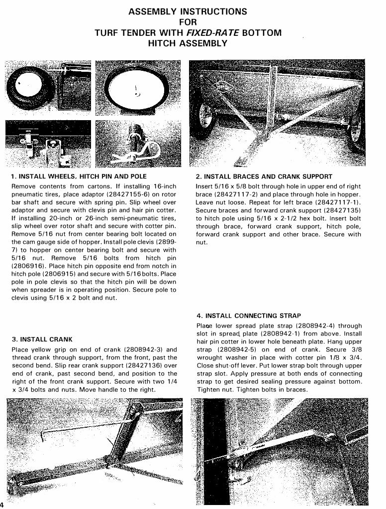
1. INSTALL WHEELS, HITCH PIN AND POLE
Remove contents from cartons. If installing 16-inch
pneumatic tires, place adaptor (28427155-6) on rotor
bar shaft and secure with spring pin. Slip wheel over
adaptor and secure with clevis pin and hair pin cotter.
If installing 20-inch or 26-inch semi-pneumatic tires,
slip wheel over rotor shaft and secure with cotter pin.
Remove 5/16 nut from center bearing bolt located on
the cam gauge side of hopper. Install pole clevis (2899-
7) to hopper on center bearing bolt and secure with
5/16 nut. Remove 5/16 bolts from hitch pin
(2806916). Place hitch pin opposite end from notch in
hitch pole (2806915) and secure with 5/16 bolts. Place
pole in pole clevis so that the hitch pin will be down
when spreader is in operating position. Secure pole to
clevis using 5/16 x 2 bolt and nut.
3. INSTALL CRANK
Place yellow grip on end of crank (2808942-3) and
thread crank through support, from the front, past the
second bend. Slip rear crank support (28427136) over
end of crank, past second bend, and position to the
right of the front crank support. Secure with two 1 /4
x 3/4 bolts and nuts. Move handle to the right.
2. INSTALL BRACES AND CRANK SUPPORT
Insert 5/16 x 5/8 bolt through hole in upper end of right
brace (28427117-2) and place through hole in hopper.
Leave nut loose. Repeat for left brace (28427117-1).
Secure braces and forward crank support (28427135)
to hitch pole using 5/16 x 2-1 /2 hex bolt. Insert bolt
through brace, forward crank support, hitch pole,
forward crank support and other brace. Secure with
nut.
4. INSTALL CONNECTING STRAP
Plane lower spread plate strap (2808942-4) through
slot in spread plate (2808942-1) from above. Install
hair pin cotter in lower hole beneath plate. Hang upper
strap (2808942-5) on end of crank. Secure 3/8
wrought washer in place with cotter pin 1 /8 x 3/4.
Close shut-off lever. Put lower strap bolt through upper
strap slot. Apply pressure at both ends of connecting
strap to get desired sealing pressure against bottom.
Tighten nut. Tighten bolts in braces.
ASSEMBLY INSTRUCTIONS
FOR
TURF TENDER WITH FIXED-RA TE BOTTOMS
HANDLE ASSEMBLY
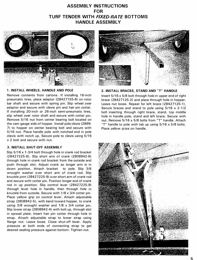
1. INSTALL WHEELS, HANDLE AND POLE
Remove contents from cartons. If installing 16-inch pneumatic tires, place adaptor (28427155-6) on rotor bar shaft and secure w·ith spring pin. Slip wheel over adaptor and secure with clevis pin and hair pin cotter. If installing 20-inch or 26-inch semi-pneumatic tires, slip wheel over rotor shaft and secure with cotter pin. Remove 5/16 nut from center bearing bolt located on the cam gauge side of hopper. Install pole clevis (2899-7) to hopper on center bearing bolt and secure with5/16 nut. Place handle pole with notched end in poleclevis with notch up. Secure pole to clevis using 5/16x 2 bolt and secure with nut.
3. INSTALL SHUT-OFF ASSEMBLY
Slip 5/16 x 1-3/4 bolt through hole in crank rod bracket (28427225-6). Slip short arm of crank (2808942-6) through hole in crank rod bracket from the outside and push through slot. Adjust crank so longer arm is in down position. Attach bracket to pole. Slip 3/8 wrought washer over short arm of crank rod. Slip knuckle joint (28427225-8) over short arm of crank rod and secure with cotter pin. Position longer end of crank rod in up position. Slip control lever (28427225-9) through lever hole in handle, then through hole in knuckle from outside. Secure with 1 /8 x 3/4 cotter pin. Place yellow grip on control lever: Attach adjustable strap (2808942-5), with bend toward hopper, to crank using 3/8 wrought washer and 1 /8 x 3/4 cotter pin. Slip lower strap (2808942-4) with bolt up, through slot in spread plate. Insert hair pin cotter through hole in strap. Attach adjustable strap to lower strap using flange nut. Leave loose. Close shut-off lever. Apply pressure at both ends of connecting strap to get desired sealing pressure against bottom. Tighten nut.
2. INSTALL BRACES, STAND AND "T" HANDLE
Insert 5/16 x 5/8 bolt through hole in upper end of right brace (28427125-2) and place through hole in hopper. Leave nut loose. Repeat for left brace (28427125-1). Secure braces and stand to pole using 5/16 x 2-1 /2 bolt inserting through right brace, stand, top middle hole in handle pole, stand and left brace. Secure with nut. Remove 5/16 x 5/8 bolts from "T" handle. Attach "T" handle to pole with tab up using 5/16 x 5/8 bolts. Place yellow mips on handle.
5

5
MAINTENANCE
EMPTY WHEN FINISHED - REMOVE
HOPPER BOTTOM AND ROTORS
1. After hopper has been emptied, pull out hair pincotters and remove wheels. Remove hair pin cotter thatconnects lever to spreading plate.
2. Loosen six latches that secure bottom and slide tohopper. (Lift spreading plate for easy access to rear latches.)
3. Loosen wing nuts on bearing retainers and removebottom.
4. Remove rotors.
5. Some materials have a fine powder in the mixture;it may be necessary to oil the bearings more often toprevent the powder fron:i working into the bearings.
IF NECESSARY, REMOVE SLIDE
FROM HOPPER FOR CLEANING.
Some materials may build up on the hopper bottom, especially when atmospheric humidity is high. It may be wise to remove the slide from the bottom for cleaning.
To remove the slide, remove the four nuts, nylon washers and slide hanger.
RE-ASSEMBLE CAREFULLY
RE-ASSEMBLE SLIDE ONTO HOPPER
BOTTOM.
For proper slide tension, gently drive the hanger to the left, using a screw driver against the tab at the right end of the hanger. When the end of the hanger lines up with the scribed line on the hopper bottom, slide tension is correct. Bottom is ready for reinstallation.
CALIBRATION
1 . DETERMINE SPEED
88 feet in one minute equals one mile per hour 176 feet in one minute equals two miles_per hour 264 feet in one minute equals three miles per hour 352 feet in one minute equals four miler per hour 440 feet in one minute equals five miles per hour 528 feet in one minute equals six miles per hour
2. SET GAUGE
Refer to rate charts included with your Turf Tender. (NOTE: for products not listed in the charts, please contact the Gandy Company for free calibration upon
submission of product.) Remember, the settings in the charts are guides, for beginning. You should check your results, as outlined in Step 3, Page 7.
You can 'fine tune' the gauge with extreme precision. The first half of the gauge is marked in increments of one. (Second half in increments of five.) If you tune to a tenth of one gauge stop (set at 27 .8 instead of 27. 7), the slide will open approximately one thousandth of an inch more. You can be sure of this because the gauge is attached directly to the slide - there is no linkage 'slack' possible.
When setting the gauge, use the top surface of the
stop as the indicator to tell you where the gauge is set.
NOTE:ALWAYS MOVE THE GAUGE AWAY FROM
THE STOP, BEFORE ATTEMPTING TO SET THE
GAUGE.
3. CHECK RATE
Making a precision application is now simply a matter
of filling up the hopper, moving the lever so the gauge
is against the stop, walking and/or driving at your
selected speed, and checking your rate.
Most rates are expressed in terms of pounds applied
per thousand square feet. Check your rate as follows.
Fill the hopper level full. Treat known area, such as
1,000 square feet. Take enough material to more than
fill the hopper full again, and weigh it. Re-fill the hopper
level full and weigh the material left over, to see how
much was applied on the 1,000 feet. If necessary,
adjust gauge up or down and make another application.
You can make the check on smaller areas, such as 500
square feet, or 250 square feet, using 1 /2 or 1 /4 of the
rate per 1,000.
It is important that you check your rate, to see that the
setting you chose from the chart is giving you the
results you want. Atmospheric conditions alone can
affect the flow of materials.
CAUTION: When applying high potency fertilizers that
will burn, be sure to be moving when you open the
slide or lower the spreading plate for application.
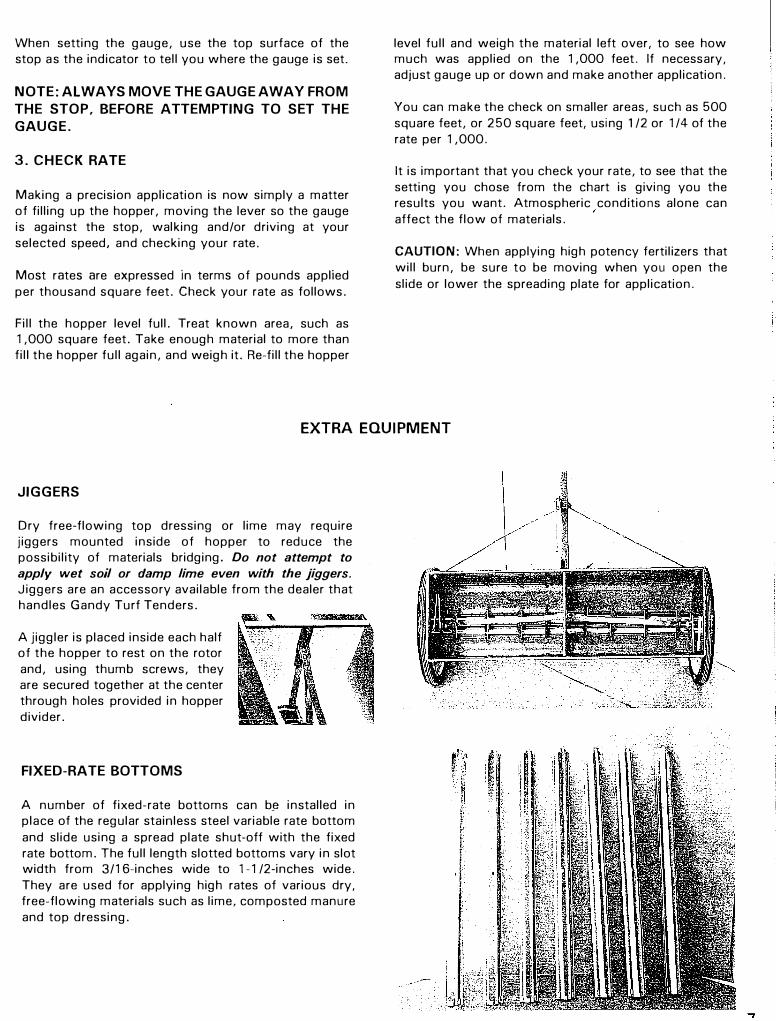
EXTRA EQUIPMENT
JIGGERS
Dry free-flowing top dressing or lime may require
jiggers mounted inside of hopper to reduce the
possibility of materials bridging. Do not attempt to
apply wet soil or damp lime even with the jiggers.
Jiggers are an accessory available from the dealer that
handles Gandy Turf Tenders.
A jiggler is placed inside each half
of the hopper to rest on the rotor
and, using thumb screws, they
are secured together at the center
through holes provided in hopper
divider.
FIXED-RATE BOTTOMS
A number of fixed-rate bottoms can b� installed in
place of the regular stainless steel variable rate bottom
and slide using a spread plate shut-off with the fixed
rate bottom. The full length slotted bottoms vary in slot
width from 3/16-inches wide to 1-1 /2-inches wide.
They are used for applying high rates of various dry,
free-flowing materials such as lime, composted manure
and top dressing.
R
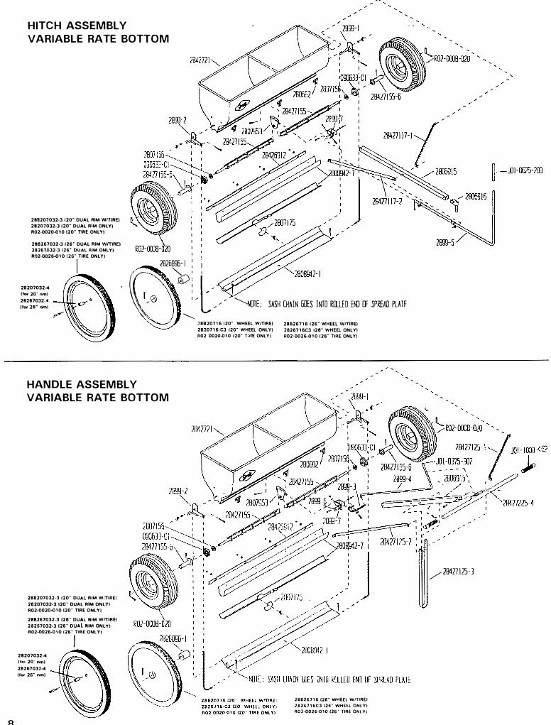
HITCH ASSEMBLY
VARIABLE RA TE BOTTOM
288207032-J 120" DUAL RIM WffiREl 28207032-3 120· DUAL RIM ONLY) R02-0020-010 120· TIRE ONL YI
288267032-3 12&9 DUAL RIM wmRE) 28267D32-J 126. DUAL RIM ONLY) R02-0026-010 125· TIRE ONLYI
28207032-4 lfw 20" nml 28267032--4 u°' 2e· nm1
(( �� i, � -e
,-l,-, , - "-!IITL �'" CHAIN ID'S 1,1□ mu□ EKJ � ��AO 1rnf
HANDLE ASS EMBLY
VARIABLE RA TE BOTTOM
288207032-3 120· DUAL RIM WlTIRE) 28207032·3 120· DUAL RIM ONLY) R02-0020--010120· TIRE ONLY]
288267032-3 (2fi. DUAL AIM WfTIRE) 28267032·3 126" DUAL RIM ONLTJ R02-0026-010 126"
('RE ONL YJ
28207032-4 Uo, 20· nm) 28267032-4 1101' 26. nml
2.8B20716120- WHEEL W/TIRE) 28B26716 126- WHEEL wmREl 2820716-CJ 120" WHEEL ONLYJ 2826716CJ 126" WHEEL ONL YI R02 0020-010 120· T:llE ONLY) R02-0026-010 12&· TIRE ONLY)
20826716 126. WHEEL WrTIAEI
2826716CJ 126" WHHL ONLYJ
R02-0026-010 126. TIRE ONL V)
/28427125-3
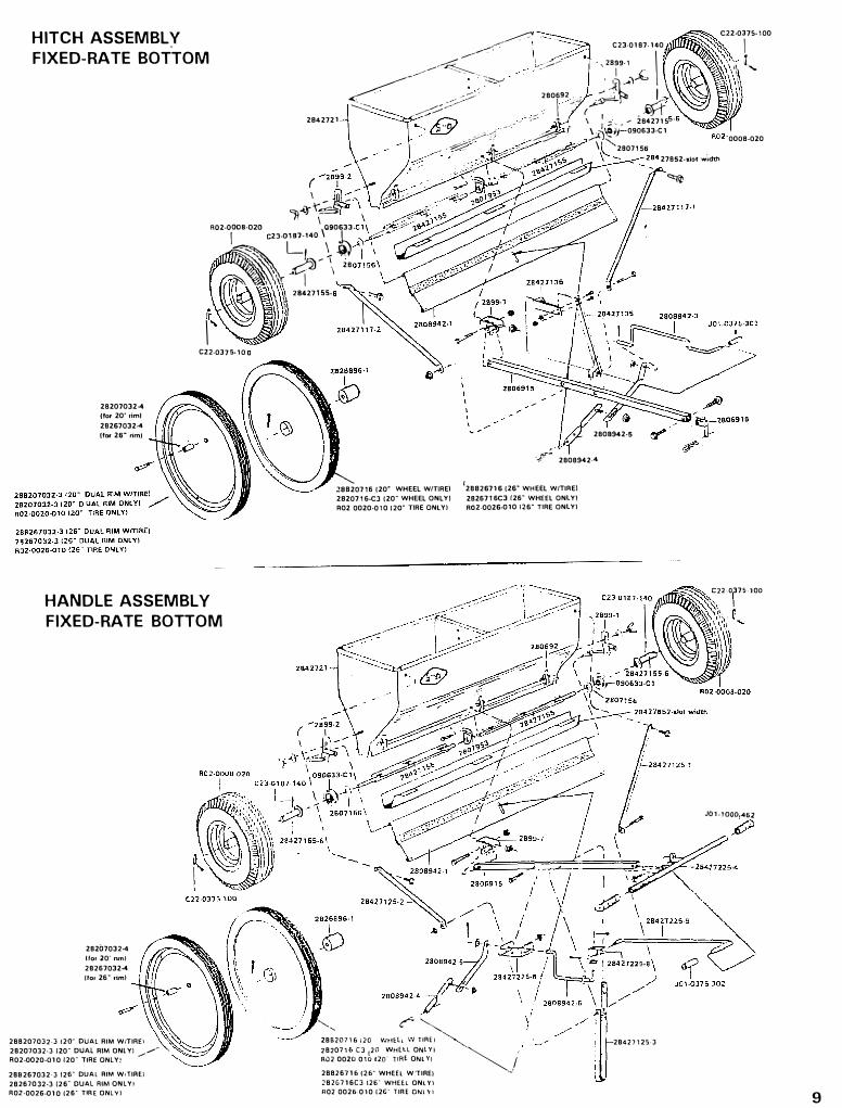
HITCH ASSEMBLY
FIXED-RA TE BOTTOM
2842721
( I
C22-0J75-100 � ·
C23-0187-140 I .-
--</ le/
··"r"·:,..:. I \ 1, • ·:::::.c �Jfl__.. I
� --- :..> 280692 .. > .,<'�?i -�
�-- ,.,-::.--;::.:..--
,-::: l < \ I .. •._ 2842715 -.:.::::::
___ . --· , \ I,;,; i_)'-090633-C 1 0008-020
··O _ --·· '."- 1 ;
.i)-s:
_/<: � - \ 1'---2eo11ss -�- ." . - .--� 27852-slotw,dth
� I -
11 .... ,-t� I 090633 Ro2-o
l;;:
23-0L;
•o \ .@
�� A�- \ 28
28207032-4 (for 20' rim) 28267032.-4 lfor 2s· rim)
1 C22-0J7 5- l 0
HANDLE ASSEMBL y
FIXED-RATE BOTTOM
28207032-4 lfor 20' nml 28267032-4 !for 26" riml
- UAL RIM W!TIRE1 288207032·3 12� �Al RIM ONLY! _.,,.,,� '\. 28207032-3 120 D .....-
R02-0020-010I20· TIRE ONLY!
• DUAL AIM W1TIAE! 28B267032·3 12� DUAL RIM ONL YI 28267032-J [26
26" TIRE ONL VI R0Z-0026-010 I
28427155-
-, ,.,. 28099-12-5
'-..,.__ • WHEEL WITIREI .:!8B20716120 - WHEEL ONLY! 2820716-C3 120
• TIRE ONLY! A02 0020-010 120
c" �
,-
-r� 2808942--4
l 26" WHEEL WfTIAEl 288267161 f26- WHEEL ONLYl 2826716C
03
10 12&· TIRE ONLY! ROZ-0026-
------... '--... l WTIAEI � 28620716;20 VhiE
� ONlYI �
' 282071& C3 !2�o�;r��L
ONLYI /
AU2 0020 010 1 --...' � WHEEL W'TIREJ 28826716 (26
- WHHL ONLY\ 282G716C3 126 2Ei" TIRE ONl 'n R02 0026·010 I
-28427125•3
C22.Q375-10D
JO 1-1000-462
9

10
PARTS LIST
PARTS NO. NO.PCS. DESCRIPTION
2842721 . . . . . . . . . . . . . . . . . . . . . . 1
280692 . . . . . . . . . . . . . . . . . . . . . 6
2807953 ..................... .
C03-0312-042 ............... .
COl-0312-030 ............... .
090633-C1 ..................... 2
2899-1 ....................... .
C02-0312-030 ............... .
C01-0312-020 ............... .
2899-2 ....................... .
C02-031 2-030 ............... .
COl-0312-020 ................ 1
28427155 ..................... 2
2807156 ...................... 2
2808942-7 . . . . . . . . . . . . . . . . . . . . . 1
C02-0250-011 . . . . . . . . . . . . . . . . 4
Hopper with latches, less bottom
Latches
Bearing, center
Hex screw TC (5/16 x 1)
Whiz lock flange nut (5/16 - 18)
Bearing, end
Retainer, end bearing, left
Wrought washer (5/16)
Wing nut (5/16 - 18)
Retainer, end bearing, right
Wrought washer (5/16)
Wing nut (5/16 - 18)
Rotor bar, tri-rod
End washer, rotor bar
Hopper bottom with rate control slide
Nylon-grip washer (1/4)
C01-0187-041
C02-0312-020
C01-0312-020
4 .......... . Kep nut ( 10 -24)
SAE washer (5/16)
Wing nut (5/16 - 18)
28426912 .................... . Slide hanger
2807175 ..................... . Cam gauge
2808942-1 . . . . . . . . . . . . . . . . . . . . . 1 Spread plate
F03-0025-016 . . . . . . . . . . . . . . . . 2 Sash chain #25, 16 link
C21-0072-020 ................ 2 ........... Hair pin cotter (.08 x 1-9/16)
C20-0093-020 . . . . . . . . . . . . . . . . 2 ........... Cotter pin (3/32 X 3/4)
M05-0.500-1 75 .................. 3.5 ft. ........ Seal. soft rubber
R02-0008-020 . . . . . . . . . . . . . . . . . . 2 ........... Pneumatic tire mounted on wheel
28427155-6 .................... 2 ........... Adaptor, wheel
C23-0187-140 . . . . . . . . . . . . . . . . 2 ........... Spring pin (3/16 x 1)
C22-0375-100 ................ 2 ........... Clevis pin (3/8 x 1-3/4)
C21-0072-020 . . . . . . . . . . . . . . . . 2 ........... Hair pin cotter (.080 x 1-9/16)
28820716 ..................... 2
2820716-C3 ................. 2
R02-0020-010 . . . . . . . . . . . . . . . . 2
2826896-1 . . . . . . . . . . . . . . . . . . 2
C20-0187-080 ............ � . . . 2
28826716 ..................... 2
2826716-C3 ................. 2
R02-0026-010 . . . . . . . . . . . . . . . . 2
2826896-1 . . . . . . . . . . . . . . . . . . 2
C20-0187-080 ................ 2
288207032-3 . . . . . . . . . . . . . . . . . . . 2
28207032-3 . . . . . . . . . . . . . . . . . 2
20-inch semi-pneumatic tire , wheel and adaptor
Wheel only, 20-inch
Semi-pneumatic tire only, 20-inch
Adaptor only
Cotter pin (3/16 x 2-1 /2)
26-inch semi-pneumatic tire, wheel and adaptor
Wheel only, 26-inch
Semi-pneumatic tire only, 26-inch
Adaptor only
Cotter pin (3/16 x 2-1 /2)
Dual rim, 20-inch with tire mounted
Dul rim only, 20-inch
R02-0020-010 ................ 2 ........... Semi-pneumatic tire only, 20-inch
28207032-4 . . . . . . . . . . . . . . . . . 12 .......... Bushing, spacer
C03-0312-090 . . . . . . . . . . . . . . . . 12 .......... Hex bolt (5/16 x 2-1 /4)
C01-0312-030 . . . . . . . . . . . . . . . . 12 .......... Flange nut (5/16)
288267032-3 . . . . . . . . . . . . . . . . . . . 2 ........... Dual rim, 26-inch with tire mounted
28267032-3 . . . . . . . . . . . . . . . . . 2 ........... Dual rim only, 26-inch
R02-0026-010 . . . . . . . . . . . . . . . . 2 .......... . Semi-pneumatic tire only, 26-inch
Bushing, spacer 28267032-4 . . . . . . . . . . . . . . . . . 12
C03-0312-090 . . . . . . . . . . . . . . . . 12
C0l-0312-030 ................ 12
Hex bolt, (5/16 x 2-1 /4)
Flange nut (5/16)
HITCH ASSEMBLY FOR VARIABLE RATE BOTTOM
2806915 ······················
2806916 . . . . . . . . . . . . . . . . . . . . . . 1
C03-031 2-021 . . . . . . . . . . . . . . . . 2
C21-0177-020 ............... .
28427117-1 ................... .
C03-0312-021 ............... .
C03-0312-090 ............... . C01-0312-030 . . . . . . . . . . . . . . . . 2
28427117-2 ................... .
C03-0312-021 ............... .
C01-0312-030 ............... .
2899-7 ....................... .
C03-0312-050
C03-0312-080 ............... .
C01-0312-030 ................ 2
2899-5 ....................... .
J01-0625-200 ............... .
........... Hitch pole
........... Hitch pin
........... Whiz lock flange bolt (5/16 x 5/8)
........... Hair pin cotter (3/16)
. .......... Pole brace, left
. .......... Whiz lock flange bolt (5/16 x 5/8)
. .......... Hex bolt (5/16 x 2-1 /4)
........... Whiz lock flange nut (5/16 - 1 8)
. .......... Pole brace, right
. .......... Whiz lock flange bolt (5/16 x 5/8)
. .......... Whiz lock flange nut (5/16 - 18)
........... Clevis, hitch pole
. .......... Hex bolt (5/16 x 1-1/4)
........... Hex bolt (5/16 x 2)
. .......... Whiz lock flange nut (5/16 • 18)
........... Shut-off lever
Yellow orio (5/8 x 2)

PARTS LIST
PART NO. NO. PCS. DESCRIPTION
HANDLE ASSEMBLY FOR VARIABLE RATE BOTTOM
2806915 ..................... .
28427125-1 ................... .
C03-0312-021 ............... .
C0l-0312-030 ............... .
28427125-2 ................... .
C03-0312-021 ............... .
co 1 -031 2-030 ............... .
2899-7 ....................... .
C03-0312-080 ............... .
COl-0312-030 ............... .
28427225-4 . . . . . . . . . . . . . . . . . . . . 1
C03-0312-021 ................ 2
J01-1000-462 . . . . . . . . . . . . . . . . 2
28427125-3 . . . . . . . . . . . . . . . . . . . . 1
C03-0312-080 . . . . . . . . . . . . . . . . 1
C0l-0312-030 ............... .
2899-3 ....................... .
2899-6 .......... , ......... .
C03-0312-070 ......... , . . . . . . 1
C02-0312-030 ................ 3
COl-0312-040 ............... .
2899-4 ....................... .
C02-0375-030
C20-0093-020
J0l-0375-302
. .......... Hitch pole
. .......... Pole brace, left
. .......... Whiz lock flange bolt (5/16 x 5/8)
........... Whiz lock flange nut (5/16 • 18)
. .......... Pole brace, right
. .......... Whiz lock flange bolt (5/16 x 5/8)
. .......... Whiz lock flange nut (5/16 - 18),
.... , ... , , . Clevis, hitch pole
. ..... , .... Hex bolt (5/16 x 2)
. .......... Whiz lock flange nut (5/16 - 18)
........... "T" handle
.. , .... , , .. Whiz lock flange bolt (5/16 x 5/8)
........ , .. Yellow grip (1 x 4 - 5/8)
. , . , , , , . . . . Stand
.... , ...... Hex bolt (5/16 x 2-1/2)
. ...... , ... Whiz lock flange nut (5/16 - 18)
, . , ........ Shut-off pivot arm
. .......... Bushing
........... Hex bolt (5/16 x 1-3/4)
......... , . Wrought washer (5/16)
. . , ... , . , .. Lock nut (5/16)
........... Shut-off lever
... , .... , .. Wrought washer (3/8)
........... Cotter pin (3/32 x 3/4)
........ , .. Yellow grip (3/8 x 3)
HITCH ASSEMBLY FOR FIXED RATE BOTTOM
2806915 ..................... .
2806916 .. , ................. : . 1
C03-0312-021 ...... , ......... 2
C21-0177-020 ............... .
28427117-1 ................... .
C03-0312-021 ............... .
C03-0312-030 ............... .
28427117-2 ................... .
C03-0312-021 ............... .
C03-0312-030 ............... .
28427135 .................... .
C03-0312-100 ............... .
COl-0312-030 ............... .
28427136 ..................... 1
C03-0250-030 . . . . . . . . . . . . . . . . 2
C0l-0250-030 ... , .. , ..... , , .. 2
2808942-5 .................... .
2808942-4 ....... , . : ....... , , . ,
C0l-0250-030 ............... .
C21-0177-020 ............... .
2899-7 ....................... .
C03-0312-080 ............... .
C0l-0312-030 ............... .
2808942-3 .................... .
C02-0375-030 ............... .
C20-0125-020
J0l-0375-302
........... Hitch pole
. .......... Hitch pin
........... Whiz lock flange bolt (5/16 x 5/8)
........... Hair pin cotter (3/16)
. .......... Pole brace, left
. .......... Whiz lock flange bolt (5/16 x 5/8)
. .. , ....... Whiz lock flange nut (5/16 - 1 8)
. . . . . . . . . . . Pole brace, right
. .......... Whiz lock flange bolt (5/16 x 5/8)
. .......... Whiz lock flange nut (5/16 - 18)
. ...... , . , . Angle post, forward crank support
. .......... Hex bolt (5/16 x 2-1 /2)
. .......... Whiz lock flange nut (5/16 - 18)
Bracket, rear crank support
Hex bolt ( 1 /4 x 3/4)
Whiz lock flange nut (1 /4 - 20)
Adjustable strap, spread plate
. .......... Lower strap, spread plate
........... Whiz lock flange nut { 1 /4 - 20)
. .......... Hair pin cotter (3/16)
. .......... Clevis, hitch pole
. .......... Hex bolt (5/16 x 2)
. .......... Whiz lock flange nut 15/16 - 18)
. .......... Shut-off crank
Wrought washer (3/8)
Cotter pin (1 /8 x 3/4)
Yellow grip (3/8 x 3)
.. ..
PARTS LIST
PART NO. NO. PCS. DESCRIPTION
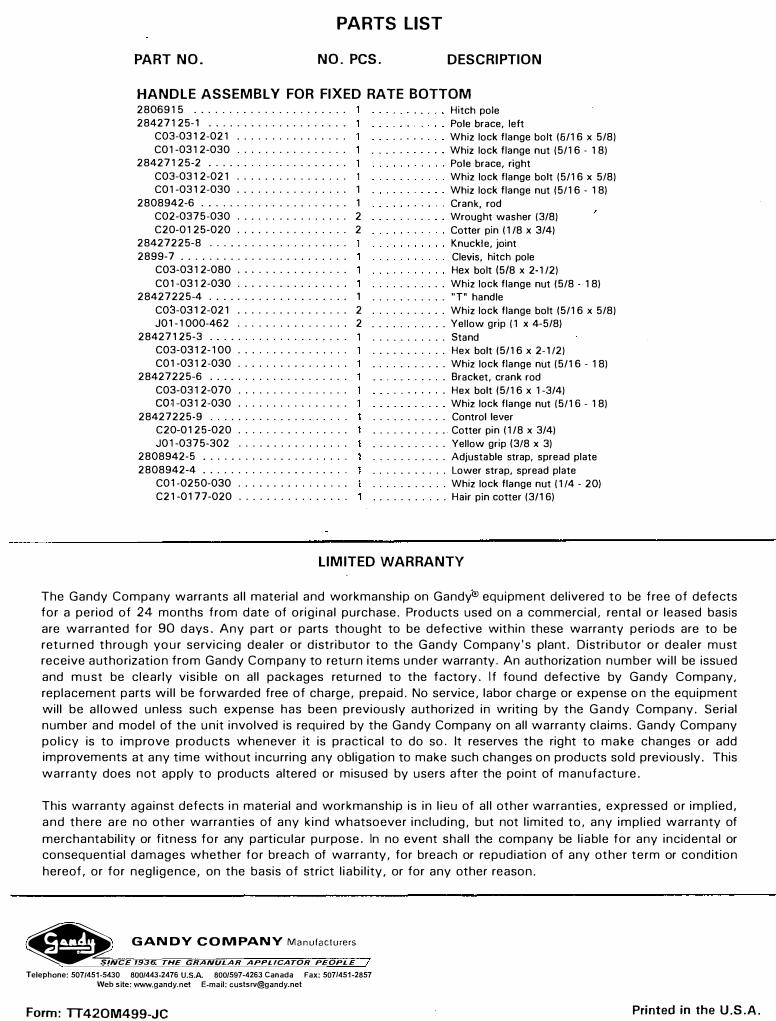
HANDLE ASSEMBLY FOR FIXED RATE BOTTOM
2806915 ..................... . 284271 25-1 ................... .
C03-0312-021 ............... .C01-0312-030 ............... .
28427125-2 ................... .C03-0312-021 ............... . C01-0312-030 ................ 1
2808942-6 . . . . . . . . . . . . . . . . . . . . . 1C02-0375-030 . . . . . . . . . . . . . . . . 2C20-0125-020 . . . . . . . . . . . . . . . . 2
28427225-8 ................... .2899-7 ....................... .
C03-0312-080 ............... .C01-0312-030 ............... .
28427225-4 . . . . . . . . . . . . . . . . . . . . 1C03-0312-021 ................ 2J01-1000-462 . . . . . . . . . . . . . . . . 2
28427125-3 ................... .C03-031 2-1 00 ............... . C01-0312-030 ............... .
28427225-6 ................... .C03-0312-070 ............... . co� -031 2-030 ............... .
28427225-9 ................... .C20-0125-020 ............... .J0l-0375-302 ............... .
2808942-5 .................... .2808942-4 .................... .
C0l-0250-030 ............... . C21-0177-020 ............... .
Hitch pole Pole brace, left Whiz lock flange bolt (6/16 x 5/8)Whiz lock flange nut (5/16 - 18)Pole brace, right Whiz lock flange bolt (5/16 x 5/8)Whiz lock flange nut (5/16 - 18)Crank, rod Wrought washer (3/8)Cotter pin (1/8 x 3/4)Knuckle, joint Clevis, hitch pole Hex bolt (5/8 x 2-1 /2)
. .......... Whiz lock flange nut (5/8 - 18)
. .......... "T" handle
........... Whiz lock flange bolt (5/16 x 5/8)
........... Yellow grip ( 1 x 4-5/8)
........... Stand
. .......... Hex bolt (5/16 x 2-1 /2)
. .......... Whiz lock flange nut (5/16 - 18)Bracket, crank rod Hex bolt (5/16 x 1-3/4) Whiz lock flange nut (5/16 - 18)
. . . . . . . . . . . Control lever
. .......... Cotter pin (1 /8 x 3/4)
. .......... Yellow grip (3/8 x 3)
. .......... Adjustable strap, spread plate
. .......... Lower strap, spread plate
. .......... Whiz lock flange nut ( 1 /4 - 20)
. .......... Hair pin cotter (3/16)
LIMITED WARRANTY
The Gandy Company warrants all material and workmanship on Gandy°® equipment delivered to be free of defects for a period of 24 months from date of original purchase. Products used on a commercial, rental or leased basis are warranted for 90 days. Any part or parts thought to be defective within these warranty periods are to be returned through your servicing dealer or distributor to the Gandy Company's plant. Distributor or dealer must receive authorization from Gandy Company to return items under warranty. An authorization number will be issued and must be clearly visible on all packages returned to the factory. If found defective by Gandy Company, replacement parts will be forwarded free of charge, prepaid. No service, labor charge or expense on the equipment will be allowed unless such expense has been previously authorized in writing by the Gandy Company. Serial number and model of the unit involved is required by the Gandy Company on all warranty claims. Gandy Company policy is to improve products whenever it is practical to do so. It reserves the right to make changes or add improvements at any time without incurring any obligation to make such changes on products sold previously. This warranty does not apply to products altered or misused by users after the point of manufacture.
This warranty against defects in material and workmanship is in lieu of all other warranties, expressed or implied, and there are no other warranties of any kind whatsoever including, but not limited to, any implied warranty of merchantability or fitness for any particular purpose. In no event shall the company be liable for any incidental or consequential damages whether for breach of warranty, for breach or repudiation of any other term or condition hereof, or for negligence, on the basis of strict liability, or for any other reason.
� GANDY COMPANY Manufacturers
�NCE 1936; THE GRANULAR APPLICATOR PEOPLE
Telephone: 507/451-5430 800/443-2476 U.S.A. 800/597-4263 Canada Fax: 507/451-2857
Web site: www.gandy.net E-mail: [email protected]
Form: TT420M499-JC Printed in the U .S .A.
Top Related