Turf Tender Service Man 2007...beam” axle assembly and rolling it out from beneath the Turf...
40
1 DAKOTA ™ TURF TENDER SERVICE MANUAL Copyright 2008 Dakota Peat and Equipment, Inc. p/n need
Transcript of Turf Tender Service Man 2007...beam” axle assembly and rolling it out from beneath the Turf...

1
DAKOTA™ TURF TENDERSERVICE MANUAL
Copyright 2008
Dakota Peat and Equipment, Inc.
p/n need

2
SPECIFICATIONS
* 410 mounted-type dimensions are: length - 103 in. (2.61 m); width - 54 in. (1.37 m); shipping weight - 780 lb (354 Kg). Trailer-type models with optional power unit, shipping weight - 1240 lb (563 Kg); gross vehicle weight - 3030 lb (1377 Kg).** 4 ply, turf tread. Maximum Inflation Pressure of 18 PSI (124 kPa) for 26.5 in. tires and 22 PSI (152 kPa) for 33 in. tires. May be adjusted downward by user for specific application and loads. Ground Pressure: Approximately equal to tire’s inflation pressure plus 1 to 2 psi (this is the industry standard method for determination of ground pressure)
ITEM Model 410 Model 411 Model 412 Model 414 Model 420 Model 440Dimensions:Height: 54 in. (1.37 m) 54 in. (1.37 m) 67 in. (1.68 m) 79 in. (2.00 m) 67 in. (1.68 m) 79 in. (2.00 m)Length: 144 in. (3.66 m)* 144 in. (3.66 m) 144 in. (3.66 m) 188 in. (4.78 m) 172 in. (4.37 m) 192 in. (4.87 m)Width: 60 in. (1.52 m)* 60 in. (1.52 m) 81 in. (2.06 m) 96 in. (2.44 m) 81 in. (2.06 m) 96 in. (2.44 m)Hopper Capacity (level): 0.85 yd3 (0.65 m3) 0.85 yd3 (0.65 m3) 2 yd3 (1.53 m3) 4.2 yd3 (3.21 m3) 2 yd3 (1.53 m3) 4.2 yd3 (3.2 m3) 2,250 lb (1023 kg) 2,250 lb (1023 kg) 6,000 lb (2700 kg) 12,000 lb (5727 kg) 6,000 lb (2700 kg) 12,000 lb (5727 kg)Rear Spinners: Dual 24 in. (61 cm) Quick Change spinners Sand Spinners (white) Fertilizer Spinners (black) Grass Spinners (green)Spreading Width: Sand/Top Dressing Material 12-40 ft (3.7-12.2 m) Fertilizer: 12-40 ft (3.7-12.2 m) Seed: 25 ft (2.2 m)Top Dressing Speed: Variable to desired application rate 2 to 8 mph (3 to 13.9 kph)Maximum Transport Speed: Empty: 15 mph (24 kph) - Not for highway use. Loaded: Dependent on terrain conditions for safe operation.Hopper Conveyor: Rear Discharge Front and Rear Discharge Variable hydraulic speed control Spliced belt Endless belt 18 in. (45.7 cm) wide beltMetering Gate(s): Rear manual sliding Front & Rear slidingTires (Trailer-Type Models): 26.5x14x12** 33x20x16.1** 26.5x14x12** 33x16x16.1**Hydraulic System: 3-7 GPM (11.3-26.4 LPM) 4-11 GPM (15.1-41.64 LPM) 2,000-2,500 PSI (138-172 Bar) Max. 2,500 PSI (172 Bar) Max.Shipping Weight (with standard equipment): 920 lb (418 Kg) 1400 lb (636 Kg) 1,825 lb (827) 3,000 lb (1361) 2,840 (1280 Kg) 3,300 lb (1500 Kg)Gross Vehicle Weight: 3,170 lb (1441 Kg) 3,170 lb (1441 Kg) 7,825 lb (3549 Kg) 13,000 lb (5897 Kg) 8,840 lb (4020 Kg) 15,900 lb (7227 Kg)
SPECIFICATIONS
3Table of Contents
TABLE OF CONTENTSSPECIFICATIONS......................................................................................................................................... 2GENERAL INFORMATION ........................................................................................................................ 4MAINTENANCE ........................................................................................................................................... 5
ELECTRIC BRAKES ........................................................................................................................... 7HOPPER CONVEYOR BELT ............................................................................................................. 9SIDE CONVEYOR ............................................................................................................................ 11DUAL SPINNER SPREADING SYSTEM ........................................................................................ 12ELECTRICAL SYSTEM .................................................................................................................... 13Electrical Schematics ........................................................................................................................... 17HYDRAULIC SYSTEM .................................................................................................................... 23HYDRAULIC ROUTING DIAGRAMS ............................................................................................. 24
STORAGE .................................................................................................................................................... 27LUBRICATION SCHEDULE ..................................................................................................................... 27TROUBLESHOOTING ............................................................................................................................... 28
INTRODUCTION ............................................................................................................................. 28Conveyor ............................................................................................................................................ 28Spinner ................................................................................................................................................ 28Hydraulic System ................................................................................................................................. 29Electrical System ................................................................................................................................. 30410, 412, & 414 TROUBLESHOOTING FLOWCHARTS ............................................................... 31

4
GENERAL INFORMATIONBEFORE OPERATING
Prior to operating the Turf Tender, read and understandthe contents of the Operator’s Manual and the Operator’smanual of vehicle either towing or carrying the Turf Tender.Become familiar with all control functions and know how toturn the vehicle off and stop effectively.
LABELING AND TERMINOLOGYThe Turf Tender and this manual use the following terms
and symbols to bring attention to the presence of hazards ofvarious risk levels and important information concerning theuse and maintenance of the Turf Tender.
WARNING: Indicates presence of a hazard which cancause severe personal injury, death, or substantial propertydamage if ignored.
CAUTION: Indicates presence of a hazard which will orcan cause minor personal injury or property damage if ignored.
NOTE: Indicates supplementary information worthy ofparticular attention relating to installation, operation, ormaintenance of the Turf Tender but is not related to a hazardouscondition.
Be sure to follow all instructions and related precautionsas they are meant for your safety and protection.
Use only the correct replacement parts and fasteners. Rightand left-hand sides are determined by facing in the directionof forward travel.
AUTHORIZED MAINTENANCEPerform only the maintenance described in this manual that
you are qualified to perform. If major repairs are ever neededor assistance is desired, contact an Authorized DAKOTADealer for their professional service.
UNLOAD HOPPER PRIOR TO DOINGMAINTENANCE
Any material in the hopper must be removed prior toperforming maintenance on or beneath the Turf Tender.
POWER OFF MAINTENANCE ANDADJUSTMENTS
All maintenance and adjustments to the Turf Tender mustbe made with the vehicle’s parking brakes set and engine off.On trailer-type Turf Tenders the vehicle must remain coupledto the Turf Tender. Failure to do so could result in injury oreven death.
TIRESCheck the tires frequently for cracks, checks, and proper
inflation. An under inflated tire poses a significant tipping andbraking hazard and may cause an accident, injury and death.Do not attempt to jack or perform tire maintenance withmaterial in the hopper. For trailer-type Turf Tenders, therecommended tire pressure operating range is 13-18 psi (90-124 kPa) for 26.5 in. tires and 15-22 psi (115-169) for 33 in.tires. Do not exceed the maximum tire pressure listed. Tirepressure is an indication of the ground pressure the Turf Tenderhas on turf; however, using a tire pressure which is too lowmay cause tire problems and also result in nonuniform groundpressure at the tire’s face.
NOTE: For mounted-type Turf Tenders, follow thetire inflation guidelines found in the vehicle’sOperator’s Manual or on the sidewall of the tire.
RELIEVE HYDRAULIC PRESSUREBefore disconnecting or performing any work on the
hydraulic system, all pressure in the system must be relievedby turning all Turf Tender control switches to their OFFposition, placing the hydraulic supply valve in the float position,and stopping the engine of the vehicle.
Residual hydraulic pressure may still be present, so caremust be taken. Make sure parts of the Turf Tender actuatedby hydraulic pressure are supported or otherwise restrainedto prevent movement prior to relieving hydraulic pressure.Failure to do so could result in damage, injury or even death.
KEEP TURF TENDER CLEANKeep the Turf Tender free of excessive grass, leaves, and
accumulations of dirt and sand. Materials such as this cancompromise seals and bearings.
REPLACEMENT PARTSTo ensure optimum performance and safety, always
purchase genuine DAKOTA replacement parts andaccessories. NEVER USE “WILL-FIT” REPLACEMENTPARTS AND ACCESSORIES MADE BY OTHERMANUFACTURERS. Using unapproved replacement partsand accessories voids the warranty of the DAKOTA TurfTender.
GENERAL INFORMATION
5
MAINTENANCE
MAINTENANCE
WARNINGAfter all repairs and/or adjustments, always test theTurf Tender before operating. Failure to do mayresult in injury or even death.
WARNINGTire and wheel mounting and demounting can bedangerous and must only be done by trainedpersonnel using proper tools and procedures.Failure to comply with safety procedures andinformation contained here can result in seriousinjury or even death.
TiresThe tires on the Turf Tender are designed to provide good
flotation (less compaction) under normal circumstances. It isimportant to check tire pressure on all tires periodically toensure they are properly inflated. Proper inflation will extendwear and provide good flotation. The recommended tirepressure operating range is 13-18 psi (90-124 kPa) for 26.5in. tires and 15-22 psi (115-169) for 33 in. tires. Do not exceedthe maximum tire pressure listed.
WARNINGOperation of the Turf Tender with improperlyinflated tires could result in serious injury or evendeath due to the potential rollover under certainconditions such as operating on a hillside.
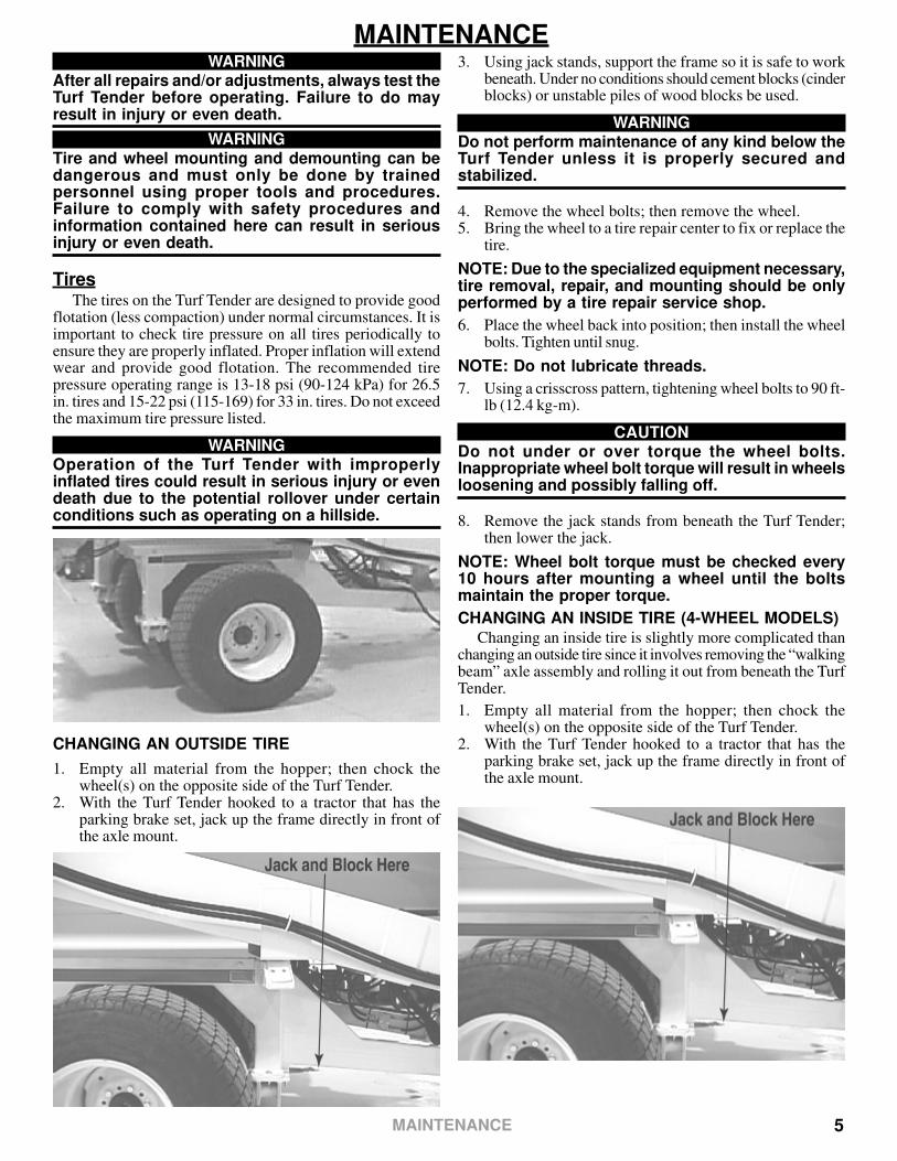
CHANGING AN OUTSIDE TIRE
1. Empty all material from the hopper; then chock thewheel(s) on the opposite side of the Turf Tender.
2. With the Turf Tender hooked to a tractor that has theparking brake set, jack up the frame directly in front ofthe axle mount.
3. Using jack stands, support the frame so it is safe to workbeneath. Under no conditions should cement blocks (cinderblocks) or unstable piles of wood blocks be used.
WARNINGDo not perform maintenance of any kind below theTurf Tender unless it is properly secured andstabilized.
4. Remove the wheel bolts; then remove the wheel.5. Bring the wheel to a tire repair center to fix or replace the
tire.
NOTE: Due to the specialized equipment necessary,tire removal, repair, and mounting should be onlyperformed by a tire repair service shop.
6. Place the wheel back into position; then install the wheelbolts. Tighten until snug.
NOTE: Do not lubricate threads.
7. Using a crisscross pattern, tightening wheel bolts to 90 ft-lb (12.4 kg-m).
CAUTIONDo not under or over torque the wheel bolts.Inappropriate wheel bolt torque will result in wheelsloosening and possibly falling off.
8. Remove the jack stands from beneath the Turf Tender;then lower the jack.
NOTE: Wheel bolt torque must be checked every10 hours after mounting a wheel until the boltsmaintain the proper torque.
CHANGING AN INSIDE TIRE (4-WHEEL MODELS)Changing an inside tire is slightly more complicated than
changing an outside tire since it involves removing the “walkingbeam” axle assembly and rolling it out from beneath the TurfTender.
1. Empty all material from the hopper; then chock thewheel(s) on the opposite side of the Turf Tender.
2. With the Turf Tender hooked to a tractor that has theparking brake set, jack up the frame directly in front ofthe axle mount.

6
3. Using jack stands, support the frame so it is safe to workbeneath. Under no conditions should cement blocks (cinderblocks) or unstable piles of wood blocks be used.
WARNINGDo not perform maintenance of any kind below theTurf Tender unless it is properly secured andstabilized.
4. Remove the walking beam axle mounting bolts and nuts(front & rear). Roll axle assembly out to the rear.
5. Stand the axle assembly on end and remove the wheelbolts; then remove the wheel.
6. Bring the wheel to a tire repair center to fix or replace thetire.
NOTE: Due to the specialized equipment necessary,tire removal, repair, and mounting should be onlyperformed by a tire repair service shop.
7. Place the wheel back into position; then install the wheelbolts. Tighten until snug.
NOTE: Do not lubricate threads.
8. Using a crisscross pattern, tightening wheel bolts to 90 ft-lb (12.4 kg-m).
CAUTIONDo not under or over torque the wheel bolts.Inappropriate wheel bolt torque will result in wheelsloosening and possibly falling off.
9. Roll the axle assembly back under the Turf Tender andinstall the eight bolts and nuts securing it to the frame.Tighten the hardware to 75 ft-lb (10.3 kg-m).
10. Remove the jack stands from beneath the Turf Tender;then lower the jack.
NOTE: Wheel bolt torque must be checked every10 hours after mounting a wheel until the boltsmaintain the proper torque.
Axle LubricationLarger Turf Tender models come equipped with 2
independent walking beam axles. The walking beam axles needregular greasing maintenance. There are grease points on thefront and rear of each axle assembly. General lithium greasemay be used for a lubricant. See the lubrication schedule forproper lubrication application.
Wheel BearingsThe wheel bearings should be repacked with grease and
the seals inspected annually under normal use and conditions.This procedure should be done more often if you are using theTurf Tender every day or if working with extremely abrasivematerials or fertilizers.
NOTE: For Turf Tender models with only one wheelon each side, ignore the steps referencing thewalking beam axles.
1. Empty all material from the hopper; then chock thewheel(s) on the opposite side of the Turf Tender.
2. With the Turf Tender hooked to a tractor that has theparking brake set, jack up the frame directly in front ofthe axle mount.
3. Using jack stands, support the frame so it is safe to workbeneath. Under no conditions should cement blocks (cinderblocks) or unstable piles of wood blocks be used.
WARNINGDo not perform maintenance of any kind below theTurf Tender unless it is properly secured andstabilized.
MAINTENANCE
7
1. Connect the ground clip from the test light to a solid ground(WHITE wire) and pierce the brake wire (BLUE wire)with the point of the test light.
2. Activate the brake switch and hold. The test light shouldget steadily brighter in intensity. Release the brake switchand the test light should go out.
This test allows you to quickly see if the brake controller isfunctioning properly. If the controller tests good with a testlight, but will not work properly with a Turf Tender connected,check for a poor connection or broken wire.
NOTE: Minimum vehicle stopping distances areachieved when the wheels approach lockup. Brakelockup should be avoided as it results in poorvehicle stability and control. Depending upon load,driving surface, wheels and tires, not all brakes arecapable of wheel lockup under all conditions.
WARNINGDo not adjust the controller outside the parametersoutlined in these instructions.
General MaintenanceBRAKE ADJUSTMENT
Brakes should be adjusted: after the first 10 hours ofoperation when the brake shoes and drums have “seated,” at300 hour intervals thereafter, and as use and performancerequires. To adjust the brakes, use the following procedure:
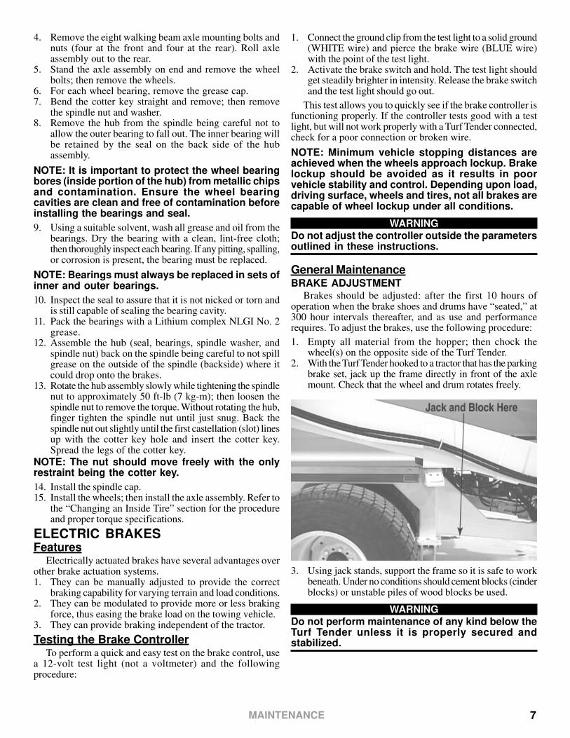
1. Empty all material from the hopper; then chock thewheel(s) on the opposite side of the Turf Tender.
2. With the Turf Tender hooked to a tractor that has the parkingbrake set, jack up the frame directly in front of the axlemount. Check that the wheel and drum rotates freely.
3. Using jack stands, support the frame so it is safe to workbeneath. Under no conditions should cement blocks (cinderblocks) or unstable piles of wood blocks be used.
WARNINGDo not perform maintenance of any kind below theTurf Tender unless it is properly secured andstabilized.
4. Remove the eight walking beam axle mounting bolts andnuts (four at the front and four at the rear). Roll axleassembly out to the rear.
5. Stand the axle assembly on end and remove the wheelbolts; then remove the wheels.
6. For each wheel bearing, remove the grease cap.7. Bend the cotter key straight and remove; then remove
the spindle nut and washer.8. Remove the hub from the spindle being careful not to
allow the outer bearing to fall out. The inner bearing willbe retained by the seal on the back side of the hubassembly.
NOTE: It is important to protect the wheel bearingbores (inside portion of the hub) from metallic chipsand contamination. Ensure the wheel bearingcavities are clean and free of contamination beforeinstalling the bearings and seal.
9. Using a suitable solvent, wash all grease and oil from thebearings. Dry the bearing with a clean, lint-free cloth;then thoroughly inspect each bearing. If any pitting, spalling,or corrosion is present, the bearing must be replaced.
NOTE: Bearings must always be replaced in sets ofinner and outer bearings.
10. Inspect the seal to assure that it is not nicked or torn andis still capable of sealing the bearing cavity.
11. Pack the bearings with a Lithium complex NLGI No. 2grease.
12. Assemble the hub (seal, bearings, spindle washer, andspindle nut) back on the spindle being careful to not spillgrease on the outside of the spindle (backside) where itcould drop onto the brakes.
13. Rotate the hub assembly slowly while tightening the spindlenut to approximately 50 ft-lb (7 kg-m); then loosen thespindle nut to remove the torque. Without rotating the hub,finger tighten the spindle nut until just snug. Back thespindle nut out slightly until the first castellation (slot) linesup with the cotter key hole and insert the cotter key.Spread the legs of the cotter key.
NOTE: The nut should move freely with the onlyrestraint being the cotter key.
14. Install the spindle cap.15. Install the wheels; then install the axle assembly. Refer to
the “Changing an Inside Tire” section for the procedureand proper torque specifications.
ELECTRIC BRAKESFeatures
Electrically actuated brakes have several advantages overother brake actuation systems.1. They can be manually adjusted to provide the correct
braking capability for varying terrain and load conditions.2. They can be modulated to provide more or less braking
force, thus easing the brake load on the towing vehicle.3. They can provide braking independent of the tractor.
Testing the Brake ControllerTo perform a quick and easy test on the brake control, use
a 12-volt test light (not a voltmeter) and the followingprocedure:
MAINTENANCE

8 MAINTENANCE
CAUTIONDo not lift or support the Turf Tender on any part ofthe axle or the suspension system. All lifting andsupport must be done on the frame directly in frontof the axle mount point.
4. Remove the cover from the adjusting slot on the bottom ofthe brake backing plate.
5. Using a screwdriver or standard brake adjusting tool, rotate thestarwheel of the adjuster assembly to expand the brake shoes.Adjust the brake shoes out until the pressure of the liningsagainst the drum makes the wheel very difficult to turn.
6. Rotate the starwheel in the opposite direction until the wheelturns freely with a slight lining drag.
7. Install the cover and lower the wheel to the ground. Repeatprocedure on all brakes.
BRAKE CLEANING AND INSPECTIONThe brakes must be inspected and serviced at yearly
intervals (more often as use and performance requires).Magnets and shoes must be changed when they become wornor scored thereby preventing adequate braking. Be sure toclean the backing plate, magnet arm, magnet, and brake shoes.
Make certain that all the parts removed are installed in thesame brake and drum assembly. Inspect the magnet arm forany loose or worn parts. Check shoe return springs, hold downsprings, and adjuster springs for stretch or deformation; replaceif required.
BRAKE LUBRICATIONBefore assembling, apply a light film of Lubriplate or Anti-Seize
compound on the brake anchor pin, the actuating arm bushing andpin, and the areas on the backing plate that are in contact with thebrake shoes and magnet lever arm. Apply a light film of grease onthe actuating block mounted on the actuating arm.
CAUTIONDo not get grease or oil on the brake linings, drums,or magnets.
MAGNETSThe electric brakes are equipped with high quality
electromagnets that are designed to provide the proper inputforce and friction characteristics. The magnets should beinspected and replaced if worn unevenly or abnormally. Checkthe magnets for wear using a straightedge.
Even if wear is normal as indicated by your straightedge,the magnets should be replaced if any part of the magnet coilhas become visible through the friction material facing of themagnet.
NOTE: It is recommended that the drum armaturesurface be re-faced when replacing magnets.
Magnets should be replaced in pairs - both outer sets and/or both inner sets. Use only genuine DAKOTA replacementparts when replacing the magnets.
SHOES AND LININGSA visual inspection of your brake linings will indicate if
they are in need of replacement. Replacement is necessary ifthe lining is worn to 1/16 in. (1.5 mm) or less, contaminatedwith grease or oil, or abnormally scored or gouged. Hairlineheat cracks are normal in bonded linings and is not a causefor concern. To retain the “balance” of your brakes, it isimportant to replace both shoes on each brake and both brakesof the same set (inner and/or outer).
TroubleshootingMost electric brake malfunctions that cannot be corrected
by either brake or controller adjustments, can generally betraced to electrical system failure. Mechanical causes areordinarily obvious, i.e. bent or broken parts, worn out liningsor magnets, seized lever arms or shoes, scored drums, looseparts, etc. A voltmeter and ammeter are essential tools forproper troubleshooting of electric brakes.
MEASURING VOLTAGE
Brake system voltage is measured at the magnets byconnecting the voltmeter to the two magnet lead wires at anybrake. This is accomplished using pin probes inserted throughthe insulation of the wires dropping down from the chassis.The engine of the towing vehicle should be running whenchecking the voltage so that low battery voltage will notadversely affect the readings.
Voltage in the brake system is designed to modulate (beginat 0 volts and, as the brake switch is held in the ON position,gradually increase [modulate] to about 12 volts). If nomodulation occurs (immediate high voltage applied to thebrakes just when the controller begins to apply voltage), adjustand/or troubleshoot the brake system.
The threshold voltage of the controller is the voltage appliedto the brakes when the controller is first applied. The lowerthe threshold voltage, the smoother the brakes will operate.Too high of a threshold voltage (in excess of 2 volts as quiteoften found in heavy duty controllers) can cause grabby, harshbrakes.

9
MEASURING AMPERAGESystem amperage is the amperage being drawn by all
brakes on the Turf Tender. The engine of the towing vehicleshould be running when checking amperage.
Measure system amperage at the BLUE controller wire(the output to the brakes). The BLUE wire must first bedisconnected and the ammeter put in series into the line. Makesure the ammeter has sufficient capacity to handle the currentdraw of about 6 amps. To prevent damaging the ammeter, besure to observe polarity.
Individual amperage draw can be measured by insertingthe ammeter in the line at the magnet you want to check.Disconnect one of the magnet lead wire connectors and attachthe ammeter between the two wires. Make sure that the wiresare properly connected and sealed after the testing iscompleted.
By far, the most common electrical problem is eitherlow or no voltage and amperage at the brakes. Commoncauses of this condition are:1. Poor electrical connections2. Open circuit(s)3. Insufficient wire size4. Broken wires5. Damaged circuit breaker (use of a fuse is not recommended).6. Improperly functioning switch, controller, or resistors
Another brake system electrical problem may be shortedor partially shorted circuits (indicated by abnormally highsystem amperage). These are occasionally the most difficultto find. Possible causes are:1. Shorted magnet coils2. Defective controller3. Bare wires contacting a grounded object
Finding a short in the wiring system is a matter of isolation.If the high amperage reading drops to zero by unplugging thewiring harness, the short is in the Turf Tender. If the amperagereading remains high with all the brake magnets disconnected,the short is in the wiring leading to the Turf Tender.
All electrical troubleshooting procedures should start at thecontrol box switch and then to the controller. Most problemsregarding brake harshness or malfunctions are traceable toimproperly adjusted or non-functioning controllers. See thecontroller information for proper adjustment and testingprocedures previously discussed. If the voltage and amperageare not satisfactory, proceed to the connector and then to theindividual magnets to isolate the problem source. 12 volts outputat the controller should equate to 10.5 volts minimum at eachmagnet. Nominal system amperage at 12 volts withmagnets at normal operating temperatures (i.e. not coldand controller at maximum gain) should be about 6 ampswith full braking force applied.
HOPPER CONVEYOR BELTBelt Adjustment
Due to stretching of the belting material with use, it will benecessary to periodically tighten the conveyor belt. Pressureon the belt and warm temperatures will increase the frequencyof belt tightening. The belt should be loosened if the Turf Tenderwill not be used for an extended period of time or will bemoving to a colder operating temperature due to seasonal orgeographic changes.
NOTE: If the belt was loosened for storage or anyother reason, the belt will need to be tightenedbefore using the Turf Tender.
CAUTIONAlways tighten the belt at the front roller. Adjustingthe rear roller will affect the material placement onthe twin spinners and may affect belt tracking.
To tighten the main conveyor belt, use the followingprocedure:1. On drive motor side of the Turf Tender, loosen the two
nuts securing the drive motor mount to the hopper frame.2. Loosen the jam nut on each of the tensioning bolts.
3. Using a ¾ inch wrench, turn each tensioning bolt clockwise1-2 complete turns. Be sure to make equal adjustmentson both sides.
NOTE: Failure to adjust the belt equally on bothsides could result in improper belt alignment anddamage to the belt. If the belt doesn’t stay on track,the belt may not be tightened equally on both sides.
4. Test the belt to see if it is properly tensioned.5. When the belt is properly tensioned, secure the adjustment
by tightening the two jam nuts against the frame and thetwo drive motor mount nuts.
6. Run the conveyor to make sure belt doesn’t slip andremains running on track.
WARNINGDo not attempt to tighten the conveyor belt whenthe tractor is running or with the Turf Tenderoperating.
Belt ReplacementSPLICED BELT
If it becomes necessary to replace the spliced mainconveyor belt, use the following procedure:
MAINTENANCE
10
NOTE: DAKOTA sells replacement kits composedof a spliced belt and wire splice pin. The splice pinconnects the two halves of the splice.
1. Run the conveyor until the belt splice is close to the frontof the Turf Tender; then shut the vehicle’s engine off.
WARNINGMake sure the vehicle’s engine is not runningbefore starting the belt replacement procedure.
2. Loosen the jam nut securing each of the four belttensioning bolts (on both sides, front and rear).
3. On drive motor side (front and back) of the Turf Tender,loosen the two nuts securing the drive motor mount to thehopper frame.
4. Loosen the four belt tensioning bolts (one on each side ofboth the front and rear rollers). Make sure you looseneach tensioning bolt the same number of turns.
5. Rotate the loose belt until the splice is at the front of theTurf Tender.
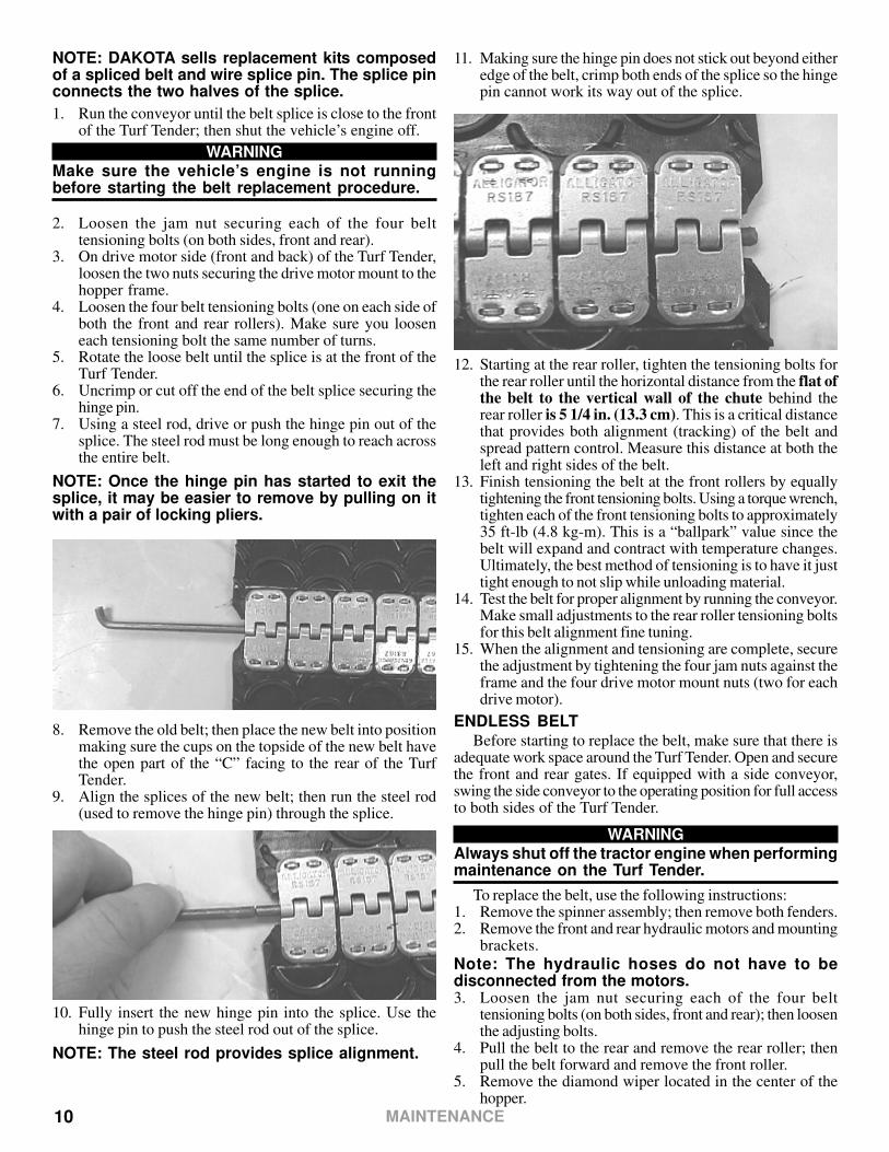
6. Uncrimp or cut off the end of the belt splice securing thehinge pin.
7. Using a steel rod, drive or push the hinge pin out of thesplice. The steel rod must be long enough to reach acrossthe entire belt.
NOTE: Once the hinge pin has started to exit thesplice, it may be easier to remove by pulling on itwith a pair of locking pliers.
8. Remove the old belt; then place the new belt into positionmaking sure the cups on the topside of the new belt havethe open part of the “C” facing to the rear of the TurfTender.
9. Align the splices of the new belt; then run the steel rod(used to remove the hinge pin) through the splice.
10. Fully insert the new hinge pin into the splice. Use thehinge pin to push the steel rod out of the splice.
NOTE: The steel rod provides splice alignment.
11. Making sure the hinge pin does not stick out beyond eitheredge of the belt, crimp both ends of the splice so the hingepin cannot work its way out of the splice.
12. Starting at the rear roller, tighten the tensioning bolts forthe rear roller until the horizontal distance from the flat ofthe belt to the vertical wall of the chute behind therear roller is 5 1/4 in. (13.3 cm). This is a critical distancethat provides both alignment (tracking) of the belt andspread pattern control. Measure this distance at both theleft and right sides of the belt.
13. Finish tensioning the belt at the front rollers by equallytightening the front tensioning bolts. Using a torque wrench,tighten each of the front tensioning bolts to approximately35 ft-lb (4.8 kg-m). This is a “ballpark” value since thebelt will expand and contract with temperature changes.Ultimately, the best method of tensioning is to have it justtight enough to not slip while unloading material.
14. Test the belt for proper alignment by running the conveyor.Make small adjustments to the rear roller tensioning boltsfor this belt alignment fine tuning.
15. When the alignment and tensioning are complete, securethe adjustment by tightening the four jam nuts against theframe and the four drive motor mount nuts (two for eachdrive motor).
ENDLESS BELTBefore starting to replace the belt, make sure that there is
adequate work space around the Turf Tender. Open and securethe front and rear gates. If equipped with a side conveyor,swing the side conveyor to the operating position for full accessto both sides of the Turf Tender.
WARNINGAlways shut off the tractor engine when performingmaintenance on the Turf Tender.
To replace the belt, use the following instructions:1. Remove the spinner assembly; then remove both fenders.2. Remove the front and rear hydraulic motors and mounting
brackets.
Note: The hydraulic hoses do not have to bedisconnected from the motors.3. Loosen the jam nut securing each of the four belt
tensioning bolts (on both sides, front and rear); then loosenthe adjusting bolts.
4. Pull the belt to the rear and remove the rear roller; thenpull the belt forward and remove the front roller.
5. Remove the diamond wiper located in the center of thehopper.
MAINTENANCE

11
Note: The diamond wiper is located between theframe of the machine under the fender. It is mountedwith the UHMW plastic facing downward.6. Remove the bolts holding the belt run in place.7. Set two sawhorses in front of the hopper and pull the belt
and belt run out together. If it seems tight, the belt may beremoved from the front as well.
8. Roll the belt run over on its side and remove the old beltfrom the belt run.
9. Slide the new belt over the belt run. Make sure the cupson the belt will face the rear when the belt run is layingdown.
10. Together, tip the belt and belt run over making sure thatthe UHMW is facing up.
11. Gather all slack belting on both the top and bottom andpull to the rear.
12. On both sides of the belt run, rub a small amount of lithiumgrease along the edge to keep the belt run from stickingwhen sliding it back into position.
13. Together, slide the belt and belt run into the frame.
14. Line up the belt run with the guide pins (two in front andtwo in the rear).
15. Start, but do not tighten, all of the belt run bolts.16. Inspect each roller to be sure that it is centered in the
conveyor. Each roller is adjusted with spacers on the motorside. All slack must be pulled to the motor side when aligningthe roller. After making sure the roller is centered, placethe front roller assembly into position.
17. Pull the slack of the belt to the rear and under the beltrun; then place the rear roller assembly into position.
NOTE: To install the roller, insert the roller throughthe belt at an angle.18. Install and secure the diamond wiper making sure the
UHMW plastic facing downward.19. Tighten both the front and rear rollers until the belt is snug
(not tight). Make sure to tighten each side of both rollersequally.
20. Check to ensure that the belt feels firm when you pushdown on the inside of the conveyor. The tightness of thebelt can be adjusted when tightening the bolts securingthe belt run.
21. Tighten all of the bolts securing the belt run. Monitor thetightness of the belt inside the conveyor and adjust asneeded during tightening.
22. Install the spinner assembly. Final adjustment of the rollerscannot be made until the spinner assembly is installed.Tighten the tensioning bolts for the rear roller until thehorizontal distance from the flat of the belt to the verticalwall of the chute behind the rear roller is 5 1/4 in. (13.3cm). If you are not using the spinner package, make surethat rollers are adjusted equally on both sides.
23. After completing the rear roller adjustment and the rollerto spinner setting, finish tightening the belt at the frontroller only. Secure each roller adjustment by tighteningthe jam nuts on the adjusting bolts.
24. Install the hydraulic drive motors with mounting brackets;then install the fenders. Tighten all hardware securely.
SIDE CONVEYORBelt Adjustment
On occasion, the tension on the conveyor belt will need tobe adjusted. The belt should be loosened when the Turf Tenderwill not be used for an extended period of time. The belt willneed to be tightened after extended periods of inactivity, orwhen it becomes loose. Heavy use, as well as hot weather,could loosen the belt due to normal stretching of the belting.The belt can only be adjusted at the discharge end of theconveyor.
WARNINGAlways shut off the tractor engine when performingmaintenance on the Turf Tender.
To adjust side conveyor belt tension, use the followingprocedure:1. Loosen the four bolts (two above and two below) securing
the motor mount to the frame.
MAINTENANCE
12
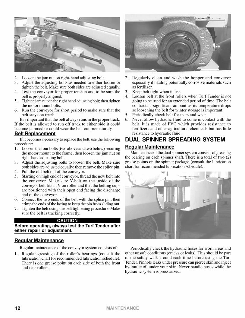
2. Loosen the jam nut on right-hand adjusting bolt.3. Adjust the adjusting bolts as needed to either loosen or
tighten the belt. Make sure both sides are adjusted equally.4. Test the conveyor for proper tension and to be sure the
belt is properly aligned.5. Tighten jam nut on the right hand adjusting bolt; then tighten
the motor mount bolts.6. Run the conveyor for short period to make sure that the
belt stays on track.It is important that the belt always runs in the proper track.
If the belt is allowed to run off track to either side it couldbecome jammed or could wear the belt out prematurely.
Belt ReplacementIf it becomes necessary to replace the belt, use the following
procedure:1. Loosen the four bolts (two above and two below) securing
the motor mount to the frame; then loosen the jam nut onright-hand adjusting bolt.
3. Adjust the adjusting bolts to loosen the belt. Make sureboth sides are adjusted equally; then remove the splice pin.
4. Pull the old belt out of the conveyor.5. Starting on high end of conveyor, thread the new belt into
the conveyor. Make sure V-belt on the inside of theconveyor belt fits in V on roller and that the belting cupsare positioned with their open end facing the dischargeend of the conveyor.
6. Connect the two ends of the belt with the splice pin; thencrimp the ends of the lacing to keep the pin from sliding out.
7. Tighten the belt using the belt tightening procedure. Makesure the belt is tracking correctly.
CAUTIONBefore operating, always test the Turf Tender aftereither repair or adjustment.
Regular Maintenance
Regular maintenance of the conveyor system consists of:
1. Regular greasing of the roller’s bearings (consult thelubrication chart for recommended lubrication schedule).There is one grease point on each side of both the frontand rear rollers.
2. Regularly clean and wash the hopper and conveyorespecially if hauling potentially corrosive materials suchas fertilizer.
3. Keep belt tight when in use.4. Loosen belt at the front rollers when Turf Tender is not
going to be used for an extended period of time. The beltcontracts a significant amount as its temperature dropsso loosening the belt for winter storage is important.
5. Periodically check belt for tears and wear.6. Never allow hydraulic fluid to come in contact with the
belt. It is made of PVC which provides resistance tofertilizers and other agricultural chemicals but has littleresistance to hydraulic fluid.
DUAL SPINNER SPREADING SYSTEM
Regular MaintenanceMaintenance of the dual spinner system consists of greasing
the bearing on each spinner shaft. There is a total of two (2)grease points on the spinner package (consult the lubricationchart for recommended lubrication schedule).
Periodically check the hydraulic hoses for worn areas andother unsafe conditions (cracks or leaks). This should be partof the safety walk around each time before using the TurfTender. Pinhole leaks under pressure can pierce skin and injecthydraulic oil under your skin. Never handle hoses while thehydraulic system is pressurized.
MAINTENANCE
13
WiringAll wiring conforms to SAE J1128 standards low tension,
PVC insulated, stranded copper wire. The PVC insulationhas a 176ºF (80ºC) temperature rating. It is important thatwires not be routed through areas having high temperatures.
Exposed wires are also encased in black, abrasion-resistantlooming wherever possible. The working temperature rangeof the loom is -34º to 200ºF (-34º to 93ºC). Again, since this alow temperature plastic, it is important that the wires are notrouted near areas with high temperatures.
The connectors used on the Turf Tender are either flatautomotive-type connectors or round “cannon” connectors.The control box may contain extra wires for options notordered. The connectors are designed to “break away” if thewires are pulled from the control box. Should damage resultto either a connector or wiring harness, a genuine DAKOTAreplacement part should be ordered and installed.
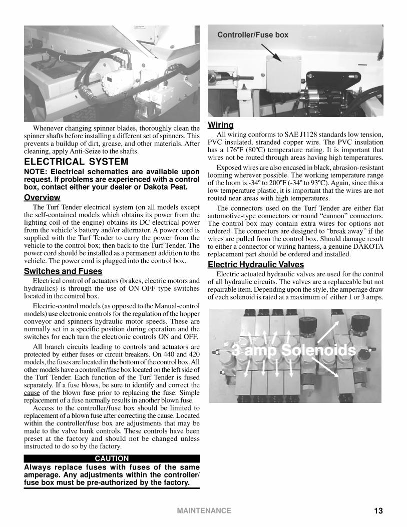
Electric Hydraulic ValvesElectric actuated hydraulic valves are used for the control
of all hydraulic circuits. The valves are a replaceable but notrepairable item. Depending upon the style, the amperage drawof each solenoid is rated at a maximum of either 1 or 3 amps.
Whenever changing spinner blades, thoroughly clean thespinner shafts before installing a different set of spinners. Thisprevents a buildup of dirt, grease, and other materials. Aftercleaning, apply Anti-Seize to the shafts.
ELECTRICAL SYSTEMNOTE: Electrical schematics are available uponrequest. If problems are experienced with a controlbox, contact either your dealer or Dakota Peat.
OverviewThe Turf Tender electrical system (on all models except
the self-contained models which obtains its power from thelighting coil of the engine) obtains its DC electrical powerfrom the vehicle’s battery and/or alternator. A power cord issupplied with the Turf Tender to carry the power from thevehicle to the control box; then back to the Turf Tender. Thepower cord should be installed as a permanent addition to thevehicle. The power cord is plugged into the control box.
Switches and FusesElectrical control of actuators (brakes, electric motors and
hydraulics) is through the use of ON-OFF type switcheslocated in the control box.
Electric-control models (as opposed to the Manual-controlmodels) use electronic controls for the regulation of the hopperconveyor and spinners hydraulic motor speeds. These arenormally set in a specific position during operation and theswitches for each turn the electronic controls ON and OFF.
All branch circuits leading to controls and actuators areprotected by either fuses or circuit breakers. On 440 and 420models, the fuses are located in the bottom of the control box. Allother models have a controller/fuse box located on the left side ofthe Turf Tender. Each function of the Turf Tender is fusedseparately. If a fuse blows, be sure to identify and correct thecause of the blown fuse prior to replacing the fuse. Simplereplacement of a fuse normally results in another blown fuse.
Access to the controller/fuse box should be limited toreplacement of a blown fuse after correcting the cause. Locatedwithin the controller/fuse box are adjustments that may bemade to the valve bank controls. These controls have beenpreset at the factory and should not be changed unlessinstructed to do so by the factory.
CAUTIONAlways replace fuses with fuses of the sameamperage. Any adjustments within the controller/fuse box must be pre-authorized by the factory.
MAINTENANCE

14
Vibrator MotorThe vibrator uses a carbon brush-type electric motor. The
brushes in the vibrator motor are a replaceable item, and afterextended use, may need to be replaced.
NOTE: The position of the counterweights insidethe vibrator have been preset from the factory andshould not be changed.
Problem Diagnosis And RepairDiagnosing electrical system problems involves identifying
the features, components, or functions which are not workingproperly; then tracking and testing the system back from there.A multimeter and two jumper wires (preferably with alligatorclips on the ends) will be needed for these tests. Most testswill be checking for the presence of voltage. Make sure themultimeter is set to DC volts (not amps or ohms) prior toconducting these tests.
COMPLETE SYSTEM FAILUREShould the whole system appear to be inactive, including
the vibrator and electric front door, when the vehicle’s engineis running and supplying electrical and hydraulic power,troubleshoot the electrical system using the following steps.The vehicle’s transmission must be in the neutral position andthe parking brake set. All tests are to be performed with theengine off so that there is no chance of accidental engagementduring the tests.
WARNINGNever perform any maintenance or troubleshootingunless the vehicle’s engine is off and the parkingbrake set.
1. Turn the master switch on the control box (if equipped) tothe ON position. The red light on the control box shouldilluminate. If the red light illuminates, the electrical problemis between the control box and the Turf Tender. If thelight does not illuminate, the problem is either with theelectrical system of the vehicle or in the wiring leading tothe control box.
2. Check the main power harness connector at the controlbox making sure it is clean and making good contact. Cleanor replace as necessary.
3. Using a multimeter set in the 12 volts DC range, checkthe voltage at the end of the main power wiring harness.Being sure to observe polarity connect the red test leadfrom the meter to the red (+) wire and the black test leadto black. Voltage greater than 11 volts should bepresent. Low voltage indicates a problem with either thevehicle’s battery or the connections of the main powerwiring harness. If there is no evidence of damage to thepower wiring harness and the connections are good,connect the main power wire harness to the control box.
NOTE: If there is a reading of zero volts, move thenegative lead from the power wire harness to a barespot on the chassis of the tractor which will give agood chassis ground. Paint is a poor conductor ofelectricity. If a voltage is present, there is a problemwith the ground (black) wire or it’s connection tothe battery. Check the connection. If the connectionis not the problem, replace the power wire harness.
MAINTENANCE
15
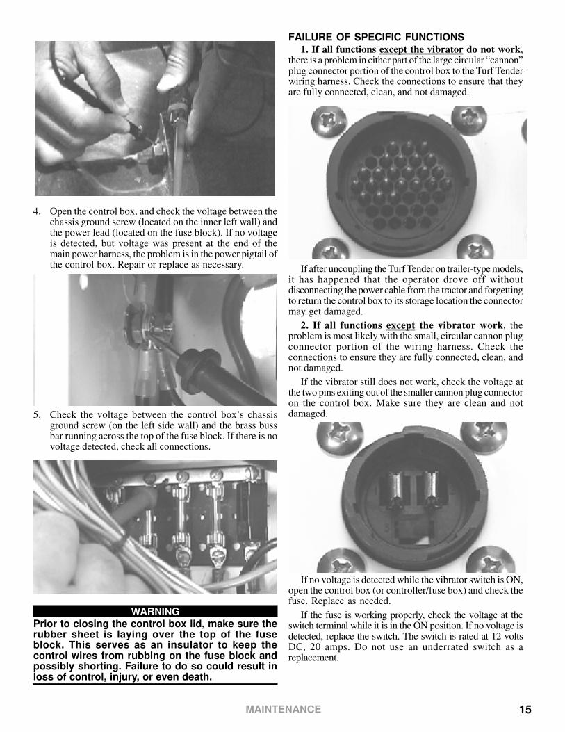
FAILURE OF SPECIFIC FUNCTIONS1. If all functions except the vibrator do not work,
there is a problem in either part of the large circular “cannon”plug connector portion of the control box to the Turf Tenderwiring harness. Check the connections to ensure that theyare fully connected, clean, and not damaged.
If after uncoupling the Turf Tender on trailer-type models,it has happened that the operator drove off withoutdisconnecting the power cable from the tractor and forgettingto return the control box to its storage location the connectormay get damaged.
2. If all functions except the vibrator work, theproblem is most likely with the small, circular cannon plugconnector portion of the wiring harness. Check theconnections to ensure they are fully connected, clean, andnot damaged.
If the vibrator still does not work, check the voltage atthe two pins exiting out of the smaller cannon plug connectoron the control box. Make sure they are clean and notdamaged.
If no voltage is detected while the vibrator switch is ON,open the control box (or controller/fuse box) and check thefuse. Replace as needed.
If the fuse is working properly, check the voltage at theswitch terminal while it is in the ON position. If no voltage isdetected, replace the switch. The switch is rated at 12 voltsDC, 20 amps. Do not use an underrated switch as areplacement.
4. Open the control box, and check the voltage between thechassis ground screw (located on the inner left wall) andthe power lead (located on the fuse block). If no voltageis detected, but voltage was present at the end of themain power harness, the problem is in the power pigtail ofthe control box. Repair or replace as necessary.
5. Check the voltage between the control box’s chassisground screw (on the left side wall) and the brass bussbar running across the top of the fuse block. If there is novoltage detected, check all connections.
WARNINGPrior to closing the control box lid, make sure therubber sheet is laying over the top of the fuseblock. This serves as an insulator to keep thecontrol wires from rubbing on the fuse block andpossibly shorting. Failure to do so could result inloss of control, injury, or even death.
MAINTENANCE

16
Check the voltage at the rear end of the wiring harnesscoming from the control box. If no voltage is detected, theproblem is most likely with the wiring harness coming fromthe control box. Repair or replace as necessary.
If the wiring harness checks out, visually check all wiresgoing back through the Turf Tender including the connectorsbehind the valve assembly. If all the wires and connectionsappear good, there may be a problem with the vibrator’s motor.Prior to removal, check for voltage at the motor. The brushesin the motor are consumable parts and are replaceable. Useonly original DAKOTA replacement parts.
3. If an individual function does not operate or doesnot change speeds when the dial is rotated, perform thesame tests listed above. The dials on the control box andsolenoid(s) on the hydraulic valve assembly may be testedusing the following illustrations. The solenoids are notserviceable parts and, although rare, may need to be replaced.
If the spinner and/or conveyor speeds do not change asthe dial (on models with speed dials on the control box) isrotated, test the dial by measuring the input voltage, outputvoltage, and output amperage. If the dial proves to befunctioning, test the resistance of the solenoid.
+ -
OFF
OFF
V
mV
mA/A
uA
V
mV
mA/A
uA
=
=
=
=
uAmA
A COM V
Multimeter
CF IN EX
COILEFC
VALVE
Fuse
Switch
Fuse
12 VDCIncoming
Power
The voltage reading shouldbe very close to the voltageread across the batteryterminals (12.6 to 15 VDC).If not, check the connectionsbetween the battery andcontroller. Be sure they areclean and tight. If batteryvoltage is low, charge orreplace the battery.
MEASURING INPUT VOLTAGE
1 2 3 4
.
.
+ -
OFF
OFF
V
mV
mA/A
uA
V
mV
mA/A
uA
=
=
=
=
uAmA
A COM V
Multimeter
CF IN EX
COILEFC
VALVE
Fuse
Switch
Fuse
12 VDCIncoming
Power
With the Master power switch in theON position and the dial on the “0”,the meter should read between 0.20and 0.25 VDC. With the dial on “100”,the meter should read between 0.95and 1.10 VDC. If the readings are outof spec, replace the dial.
MEASURING OUTPUT VOLTAGE
1 2 3 4
.
.
NOTE: Turn the Master powerswitch to the OFF positionbefore either connecting ordisconnecting the test leads.
+ -
OFF
OFF
V
mV
mA/A
uA
V
mV
mA/A
uA
=
=
=
=
uAmA
A COM V
Multimeter
CF IN EX
COILEFC
VALVE
Fuse
Switch
Fuse
12 VDCIncoming
Power
With the Master power switch in theON position and the dial on the “0”,the meter should read between 0.20and 0.25 ADC. With the dial on “100”,the meter should read between 0.94and 1.10 ADC. If the readings are outof spec, replace the dial.
MEASURING OUTPUT AMPERAGE
1 2 3 4
.
.
NOTE: Turn the Master powerswitch to the OFF positionbefore either connecting ordisconnecting the test leads.
+ -
OFF
OFF
V
mV
mA/A
uA
V
mV
mA/A
uA
=
=
=
=
uAmA
A COM V
Multimeter
CF IN EX
COILEFC
VALVE
Fuse
Switch
Fuse
12 VDCIncoming
Power
NOTE: Make sure the Masterpower switch is in the OFFposition when conductingthis test.
The solenoid should have a resistance of 9.6 ohms + 1ohm @ 77° F. If the readingis out of spec, the solenoidis defective.
-
MEASURING SOLENOID RESISTANCE
1 2 3 4
MAINTENANCE
17
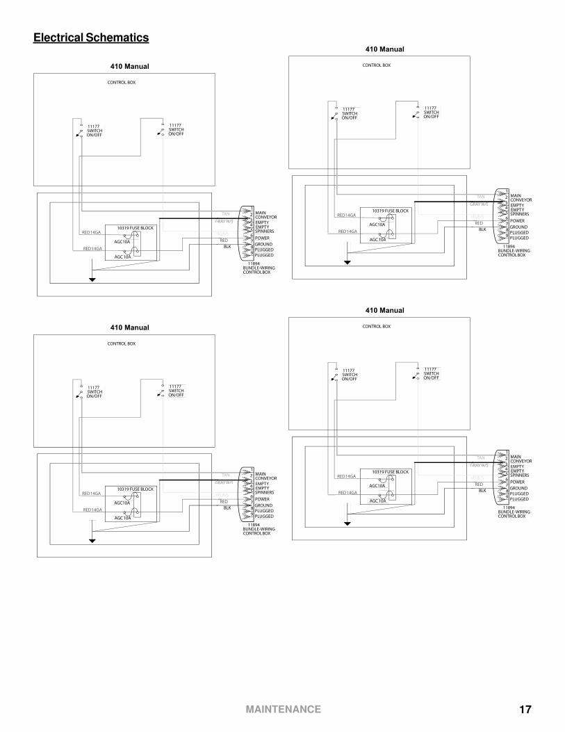
Electrical Schematics
410 Manual
YEL B/S
TAN
RED
MAINCONVEYOR
EMPTY
SPINNERS
POWER
GROUND
10319 FUSE BLOCK
AGC10A
AGC 10A
RED 14GA
RED 14GA
11177SWITCHON/OFF
11177SWITCHON/OFF
BLK
GRAY W/SWW
11894BUNDLE-WIRINGCONTROL BOX
PLUGGED
PLUGGED
1
2
345
6
7
8
9
EMPTY
CONTROL BOX
410 Manual
YEL B/S
TAN
RED
MAINCONVEYOR
EMPTY
SPINNERS
POWER
GROUND
10319 FUSE BLOCK
AGC10A
AGC 10A
RED 14GA
RED 14GA
11177SWITCHON/OFF
11177SWITCHON/OFF
BLK
GRAY W/SWW
11894BUNDLE-WIRINGCONTROL BOX
PLUGGED
PLUGGED
1
2
345
6
7
8
9
EMPTY
CONTROL BOX
410 Manual
YEL B/S
TAN
RED
MAINCONVEYOR
EMPTY
SPINNERS
POWER
GROUND
10319 FUSE BLOCK
AGC10A
AGC 10A
RED 14GA
RED 14GA
11177SWITCHON/OFF
11177SWITCHON/OFF
BLK
GRAY W/SWW
11894BUNDLE-WIRINGCONTROL BOX
PLUGGED
PLUGGED
1
2
345
6
7
8
9
EMPTY
CONTROL BOX
410 Manual
YEL B/S
TAN
RED
MAINCONVEYOR
EMPTY
SPINNERS
POWER
GROUND
10319 FUSE BLOCK
AGC10A
AGC 10A
RED 14GA
RED 14GA
11177SWITCHON/OFF
11177SWITCHON/OFF
BLK
GRAY W/SWW
11894BUNDLE-WIRINGCONTROL BOX
PLUGGED
PLUGGED
1
2
345
6
7
8
9
EMPTY
CONTROL BOX
MAINTENANCE

18
410 Manual
YEL B/S
TAN
RED
MAINCONVEYOR
EMPTY
SPINNERS
POWER
GROUND
10319 FUSE BLOCK
AGC10A
AGC 10A
RED 14GA
RED 14GA
11177SWITCHON/OFF
11177SWITCHON/OFF
BLK
GRAY W/SWW
11894BUNDLE-WIRINGCONTROL BOX
PLUGGED
PLUGGED
1
2
345
6
7
8
9
EMPTY
CONTROL BOX
410 Manual
YEL B/S
TAN
RED
MAINCONVEYOR
EMPTY
SPINNERS
POWER
GROUND
10319 FUSE BLOCK
AGC10A
AGC 10A
RED 14GA
RED 14GA
11177SWITCHON/OFF
11177SWITCHON/OFF
BLK
GRAY W/SWW
11894BUNDLE-WIRINGCONTROL BOX
PLUGGED
PLUGGED
1
2
345
6
7
8
9
EMPTY
CONTROL BOX
410 Manual
YEL B/S
TAN
RED
MAINCONVEYOR
EMPTY
SPINNERS
POWER
GROUND
10319 FUSE BLOCK
AGC10A
AGC 10A
RED 14GA
RED 14GA
11177SWITCHON/OFF
11177SWITCHON/OFF
BLK
GRAY W/SWW
11894BUNDLE-WIRINGCONTROL BOX
PLUGGED
PLUGGED
1
2
345
6
7
8
9
EMPTY
CONTROL BOX
410 Manual
YEL B/S
TAN
RED
MAINCONVEYOR
EMPTY
SPINNERS
POWER
GROUND
10319 FUSE BLOCK
AGC10A
AGC 10A
RED 14GA
RED 14GA
11177SWITCHON/OFF
11177SWITCHON/OFF
BLK
GRAY W/SWW
11894BUNDLE-WIRINGCONTROL BOX
PLUGGED
PLUGGED
1
2
345
6
7
8
9
EMPTY
CONTROL BOX
MAINTENANCE
19
SPINNERS SPEEDCONVEYOR SPEEDDAKOTA
SPINNERS
OFF
ON
60
70
80
100
90
40
30
20
0
10
50
SPINNERS SPEED
ADJUSTMENT
CONVEYOR SPEED
ADJUSTMENT
ON
OFF
CONVEYOR
OFF
ON
POWER
RUN
STARTOFF
MASTER
DAKOTA
50
10
0
30
40
100
60
80
70
20
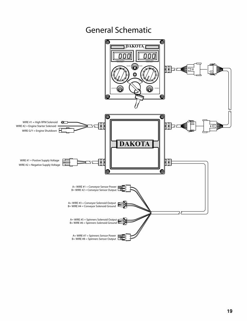
A= WIRE #7 = Spinners Sensor PowerB= WIRE #8 = Spinners Sensor Output
A= WIRE #5 = Spinners Solenoid OutputB= WIRE #6 = Spinners Solenoid Ground
A= WIRE #3 = Conveyor Solenoid OutputB= WIRE #4 = Conveyor Solenoid Ground
A= WIRE #1 = Conveyor Sensor PowerB= WIRE #2 = Conveyor Sensor Output
B
P.E.D.
AA
P.E.D.
B
BA
AB
WIRE #2 = Engine Starter Solenoid
WIRE #1 = High RPM Solenoid
WIRE G/Y = Engine Shutdown
WIRE #1 = Postive Supply Voltage
WIRE #2 = Negative Supply Voltage
General Schematic

20
DAKOTA
12V BATTERY
15A
FUSE
NOTE: 15A FUSE SHOULD BE LOCATED 15" MAXIMUM
FROM POSTIVE BATTERY TEMINAL+ -
Honda Motor Schematic
IGNITION SWITCHE IG ST BAT
E IG ST BAT
OFF
ON
START
OILLEVELSWITCH
OILALERTUNIT
FUSE
Y
Y Y
IGNITION COIL
SPARK PLUG
CONTROL BOX
M
STARTERMOTOR
BATTERYCHARGE COIL
HIGH IDLE SOLENOID
Regulator/Rectifier
+_ _ _
WBL/W
BL/R
BL
BL
W
W
W
Gr
WW
W
BLBL
W
BL/W
BL/RSOLENOID
21
31 1 3
31 1 3
TB1 TB2+ -+ -
21 1 2211 2
-+ -+TB2TB1
(BOTTOM VIEW)
Spinners Speed
Display
(BOTTOM VIEW)
Conveyor Speed
Display
Assembly
Conveyor
(Top View of Pot)
B1 B 3
B1 & B Contacts
Closed in "RUN"
Position
Ignition Switch
Both switches are
Open in "OFF" Position
Ignition Switch
B1 & 3 Contacts
Closed in "START"
Position
Master Power
"ON" LED
Red
(Bottom View)
G/Y
Spinners
Switch
Conveyor
Switch
Master Power
Switch
Gold TerminalSilver Terminal
Spinners Sensor Power
Spinners Sensor Output
Spinners Solenoid Output
Spinners Solenoid Ground
Conveyor Solenoid Output
Conveyor Solenoid Ground
Conveyor Sensor Power
Conveyor Sensor Output
A= WIRE #1 = Postive Supply Voltage
B= WIRE #2 = Negative Supply Voltage
WIRE G/Y = Engine Shutdown
WIRE #2 = Engine Starter Solenoid
WIRE #1 = High RPM Solenoid
22115
Wire #5
Wir
e #
8
Wir
e #
2
Wir
e #
1&
7
Wir
e G
/Y
Wir
e #
1
Wir
e #
2
Wir
e #
11
Wir
e #
3
Wir
e #
4
Wir
e #
5
Wir
e #
6
Wir
e #
8
Wir
e #
7
Wir
e #
9
Wir
e #
10
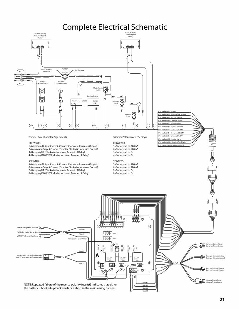
Wire marked #1 = Battery
Wire marked #2 = Signal to Spin. Display
Wire marked #3 = 10V REF. Voltage
Wire marked #4 = Conveyor Wiper
Wire marked #5 = Spinners Wiper
Wire marked #6 = Engine Shutdown
Wire marked #7 = Engine High RPM
Wire marked #8 = Converyor ON/OFF
Wire marked #9 = Spinners ON/OFF
Wire marked #10 = Engine Starter
Wire marked #11 = Signal to Con. Display
Wire Colored Green/Yellow = Ground
T4
B
P.E.D.
AA
P.E.D.
B
BA
AB
Wire #1
Wire Colored Green/Yellow
Wire #2
Wire #2
Wire #1
T8T7T6
T5 2 134
1 2 43
CR3CR2
CR1
T2
T3
T1
11 121095 6 873 421
Trimmer Potentiometer Adjustments:
CONVEYOR:
1=Minimum Output Current (Counter Clockwise Increases Output)
2=Maximum Output Current (Counter Clockwise Increases Output)
3=Ramping UP (Clockwise Increases Amount of Delay)
4=Ramping DOWN (Clockwise Increases Amount of Delay)
SPINNERS:
5=Minimum Output Current (Counter Clockwise Increases Output)
6=Maximum Output Current (Counter Clockwise Increases Output)
7=Ramping UP (Clockwise Increases Amount of Delay)
8=Ramping DOWN (Clockwise Increases Amount of Delay
Trimmer Potentiometer Settings:
CONVEYOR:
1=Factory set to: 200mA
2=Factory set to: 700mA
3=Factory set to: 0s
4=Factory set to: 0s
SPINNERS:
5=Factory set to: 200mA
6=Factory set to: 700mA
7=Factory set to: 0s
8=Factory set to: 0s
Spinners
(Top View of Pot)
Bla
ck
Blu
e
Wire #6
Wire #3
Wire #4
4 3 5 1 6 10 7 8 9 11 2
3
Vio
let
Gra
y
Gra
y
NOTE: Repeated failure of the reverse polarity fuse (A) indicates that either
the battery is hooked up backwards or a short in the main wiring harness.
A
5 6 7 8
3 421
12V 20/30A
0 332 209 151
BOSCH
Spinners
Conveyor
BOSCH
0 332 209 151
20/30A12V 12V 20/30A
0 332 209 151
BOSCH
Complete Electrical Schematic

22
420/440 Control Box Wiring Schematic
Power Lead
+A-B
Red
Re
d
Re
d
Re
dR
ed
Re
d
Re
dR
ed
Re
d
Bla
ck
Bro
wn
20A20A 30A 10A10A 10A
Fuse Block
Front Door Switch
Switch
Rear Door Switch
Side Conveyor Lift Switch
Spinners/Side Conveyor Switch
Hopper Conveyor Switch
Side Conveyor Swing Switch
SwitchBrake Lead
ABCD
Ye
llo
w
GreenRed
Black
RedBlack
GRNTANGRY/WHT
BrakeRearFront
HopperConveyor
UpDown
BoxScraper
Spinners Run
Side ConveyorSwing
Side Conveyor Run
OutIn
Up
Up
DownDown
Side Conveyor
Rear Door
Front Door
Box Scraper - Float
Cannon Plug
Cannon Plug
123
ORG
12345678910111213141516171819
2120
22232425262728293031323334353637
GRN/WHTPNK/WHTGRNPRPLT BLUEGRYBLU/WHTPRP/WHTPNKTAN/WHTREDBLKWHTBLUPNK/BLKYLWORG/WHTBLK/WHTYLW/BLK
GRN
BR
N
23MAINTENANCE
HYDRAULIC SYSTEM
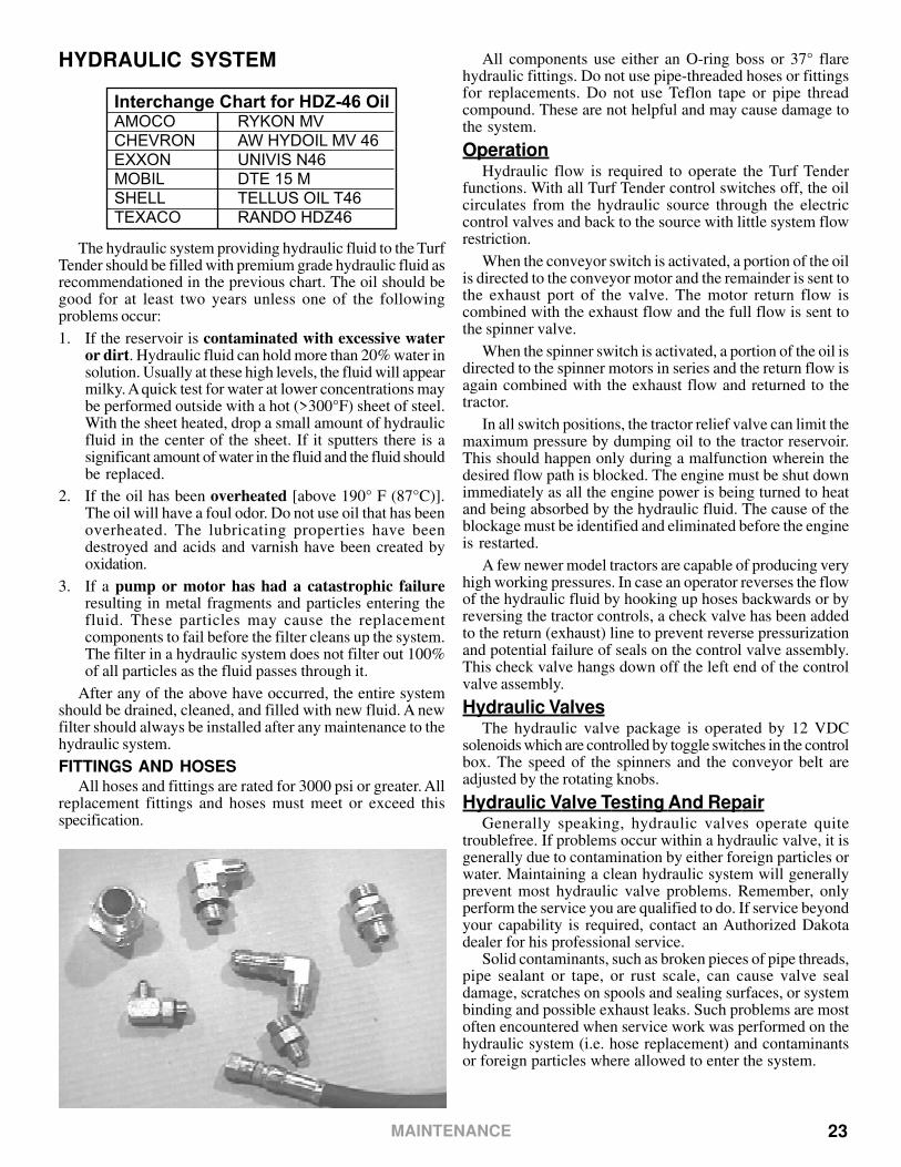
Interchange Chart for HDZ-46 Oil AMOCO RYKON MV CHEVRON AW HYDOIL MV 46 EXXON UNIVIS N46 MOBIL DTE 15 M SHELL TELLUS OIL T46 TEXACO RANDO HDZ46
The hydraulic system providing hydraulic fluid to the TurfTender should be filled with premium grade hydraulic fluid asrecommendationed in the previous chart. The oil should begood for at least two years unless one of the followingproblems occur:
1. If the reservoir is contaminated with excessive wateror dirt. Hydraulic fluid can hold more than 20% water insolution. Usually at these high levels, the fluid will appearmilky. A quick test for water at lower concentrations maybe performed outside with a hot (>300°F) sheet of steel.With the sheet heated, drop a small amount of hydraulicfluid in the center of the sheet. If it sputters there is asignificant amount of water in the fluid and the fluid shouldbe replaced.
2. If the oil has been overheated [above 190° F (87°C)].The oil will have a foul odor. Do not use oil that has beenoverheated. The lubricating properties have beendestroyed and acids and varnish have been created byoxidation.
3. If a pump or motor has had a catastrophic failureresulting in metal fragments and particles entering thefluid. These particles may cause the replacementcomponents to fail before the filter cleans up the system.The filter in a hydraulic system does not filter out 100%of all particles as the fluid passes through it.
After any of the above have occurred, the entire systemshould be drained, cleaned, and filled with new fluid. A newfilter should always be installed after any maintenance to thehydraulic system.
FITTINGS AND HOSESAll hoses and fittings are rated for 3000 psi or greater. All
replacement fittings and hoses must meet or exceed thisspecification.
All components use either an O-ring boss or 37° flarehydraulic fittings. Do not use pipe-threaded hoses or fittingsfor replacements. Do not use Teflon tape or pipe threadcompound. These are not helpful and may cause damage tothe system.
OperationHydraulic flow is required to operate the Turf Tender
functions. With all Turf Tender control switches off, the oilcirculates from the hydraulic source through the electriccontrol valves and back to the source with little system flowrestriction.
When the conveyor switch is activated, a portion of the oilis directed to the conveyor motor and the remainder is sent tothe exhaust port of the valve. The motor return flow iscombined with the exhaust flow and the full flow is sent tothe spinner valve.
When the spinner switch is activated, a portion of the oil isdirected to the spinner motors in series and the return flow isagain combined with the exhaust flow and returned to thetractor.
In all switch positions, the tractor relief valve can limit themaximum pressure by dumping oil to the tractor reservoir.This should happen only during a malfunction wherein thedesired flow path is blocked. The engine must be shut downimmediately as all the engine power is being turned to heatand being absorbed by the hydraulic fluid. The cause of theblockage must be identified and eliminated before the engineis restarted.
A few newer model tractors are capable of producing veryhigh working pressures. In case an operator reverses the flowof the hydraulic fluid by hooking up hoses backwards or byreversing the tractor controls, a check valve has been addedto the return (exhaust) line to prevent reverse pressurizationand potential failure of seals on the control valve assembly.This check valve hangs down off the left end of the controlvalve assembly.
Hydraulic ValvesThe hydraulic valve package is operated by 12 VDC
solenoids which are controlled by toggle switches in the controlbox. The speed of the spinners and the conveyor belt areadjusted by the rotating knobs.
Hydraulic Valve Testing And RepairGenerally speaking, hydraulic valves operate quite
troublefree. If problems occur within a hydraulic valve, it isgenerally due to contamination by either foreign particles orwater. Maintaining a clean hydraulic system will generallyprevent most hydraulic valve problems. Remember, onlyperform the service you are qualified to do. If service beyondyour capability is required, contact an Authorized Dakotadealer for his professional service.
Solid contaminants, such as broken pieces of pipe threads,pipe sealant or tape, or rust scale, can cause valve sealdamage, scratches on spools and sealing surfaces, or systembinding and possible exhaust leaks. Such problems are mostoften encountered when service work was performed on thehydraulic system (i.e. hose replacement) and contaminantsor foreign particles where allowed to enter the system.

24 MAINTENANCE
Continuous leakage from the exhaust port when the solenoidis de-energized can be caused by a foreign particle trappedbetween the bottom seat and the plunger, by a damaged bottomseat, or by a worn or damaged bottom plunger seal. Leakageat the exhaust port and/or solenoid buzzing when the solenoidis energized can be caused by a foreign particle lodged in thetop seat area. Leakage in this area can also be caused byworn or damaged top seats or top plunger seals.
EXCF
INLET
Manual OverrideOrifice Spring AdjustFactory PresetDo Not Adjust
NOTE: Most if not all problems are a result of aforeign particle not allowing the ball to seat.Cleaning of the seat area with WD40 or equivilentand compressed air normally returns the valve to afully operational status.
Broken springs on spring return valves can cause a valveto remain in the actuated position or to only partially returnand perhaps leak to exhaust. Broken springs must be replaced.
NOTE: The retaining nut on the top of eachhydraulic valve section requires only firm handtightening. Application of excessive force will resultin damage to the valve.
2
1
Remove nut #1.Loosen nut #2.Under #1, use a flat-bladescrewdriver, turn all the wayto stop; then turn back out.
HYDRAULIC ROUTING DIAGRAMS
Outside Valve
Inside Valve
Spinner Motor
Spinner Motor
Conveyor Motor
Pressure Return
10134
14184
101421418214180
14380
14380
CFIN EX
CFIN
410 Electric (Mounted)
14181
10844
410 Electric With Engine
Oil Tank
Pump
Outside Valve
Inside ValveSpinner
MotorSpinner
Motor
Conveyor Motor
14181 10134
14184
101421418214180
14382
CFIN EX
CFIN
14183
Outside Valve
Inside Valve
Spinner Motor
Spinner Motor
Conveyor Motor
Pressure Return
10134
14184
101421418214180
13558
14383
CFIN EX
CFIN
410 Electric Without Engine
14181

25MAINTENANCE
Front Valve Rear Valve
Spinner Motor
Conveyor Motor Return
Pressure
CF EX
IN
CF EX
IN
10134
1014213554
14296
10138
14296
11242
14380
14380
410 Manual (Mounted)
Spinner Motor
14295
Front Valve Rear Valve
Spinner Motor
Conveyor Motor Return
Pressure
CF EX
IN
CF EX
IN
10134
1014213554
14296
10138
14296
11242
10410
10165
410 Manual Without Engine
Spinner Motor
14295
Front Valve Rear Valve
Spinner Motor
Conveyor Motor
CF EX
IN
CF EX
IN
10134
1014213554
14296
10138
14296
11242
10140
10165
410 Manual With Engine
Spinner Motor
11746
Tank
Pump
10844
10127
10197
12592
14295
Outside Valve
Inside Valve
Spinner Motor
Spinner Motor
Conveyor Motor
Pressure Return
10134
12981
101421355713556
13560
13559
CFIN EX
CFIN
411 Electric
14393
Outside Valve
Inside Valve
Spinner Motor
Spinner Motor
Conveyor Motor
Pressure Return
12409
14373
124101437114370
14374
14369
CFIN EX
CFIN
412 Electric
14372
Outside Valve
Inside Valve
Spinner Motor
Spinner Motor
RearConveyor
Motor
Pressure Return
12409
14384
12410
14390
14385
14389
14388
CFIN EX
CFIN
414
14387
FrontConveyor
Motor
14386
26
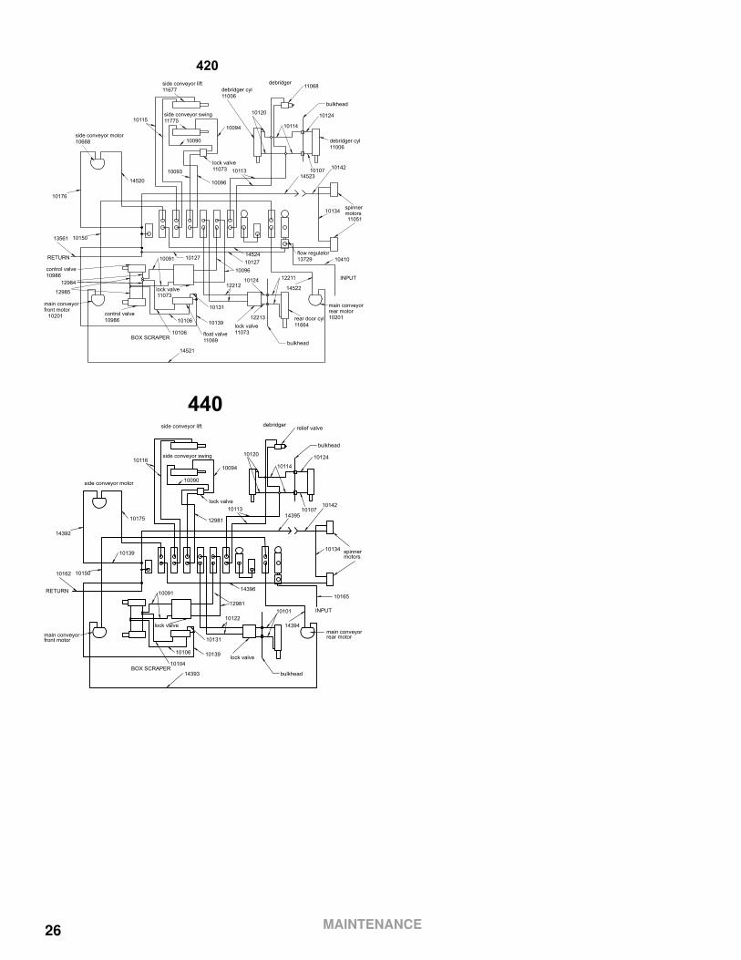
bulkhead
bulkhead
debridgerside conveyor lift11677
side conveyor swing11775
side conveyor motor10668
main conveyorfront motor
10201
main conveyorrear motor
10201
spinnermotors11051
RETURN
BOX SCRAPER
INPUT
10176
14520
10150
10142
14523
13561
1041014524
14522
10096
12212
12211
10131
1013910106
10106
10091
14521
10090
10094
10115
10093
10096
10134
11068
lock valve11073
lock valve11073
lock valve11073
10113
10120
10114
10124
10107
10127
rear door cyl11664
10124
12213
10127
float valve11069
control valve10986
control valve10986
12984
12985
debridger cyl11006
debridger cyl11006
flow regulator13729
420
bulkhead
bulkhead
debridgerside conveyor lift
side conveyor swing
side conveyor motor
main conveyorfront motor
main conveyorrear motor
spinner motors
RETURN
BOX SCRAPER
INPUT
14392
10175
10150
10142
14395
10139
10162
1016514396
1439410122
10101
10131
1013910106
10104
10091
14393
10090
10094
10116
12981
10134
relief valve
lock valve
lock valve
lock valve
10113
10120
10114
10124
10107
440
12981
MAINTENANCE
27
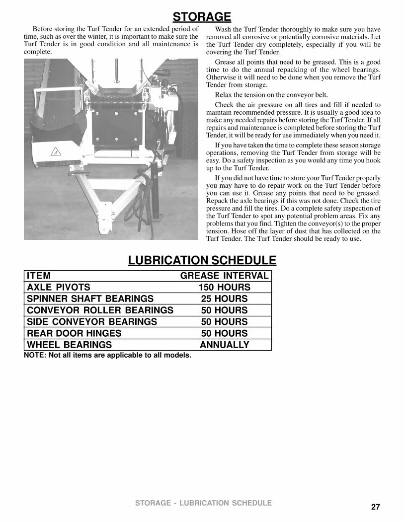
STORAGEBefore storing the Turf Tender for an extended period of
time, such as over the winter, it is important to make sure theTurf Tender is in good condition and all maintenance iscomplete.
Wash the Turf Tender thoroughly to make sure you haveremoved all corrosive or potentially corrosive materials. Letthe Turf Tender dry completely, especially if you will becovering the Turf Tender.
Grease all points that need to be greased. This is a goodtime to do the annual repacking of the wheel bearings.Otherwise it will need to be done when you remove the TurfTender from storage.
Relax the tension on the conveyor belt.
Check the air pressure on all tires and fill if needed tomaintain recommended pressure. It is usually a good idea tomake any needed repairs before storing the Turf Tender. If allrepairs and maintenance is completed before storing the TurfTender, it will be ready for use immediately when you need it.
If you have taken the time to complete these season storageoperations, removing the Turf Tender from storage will beeasy. Do a safety inspection as you would any time you hookup to the Turf Tender.
If you did not have time to store your Turf Tender properlyyou may have to do repair work on the Turf Tender beforeyou can use it. Grease any points that need to be greased.Repack the axle bearings if this was not done. Check the tirepressure and fill the tires. Do a complete safety inspection ofthe Turf Tender to spot any potential problem areas. Fix anyproblems that you find. Tighten the conveyor(s) to the propertension. Hose off the layer of dust that has collected on theTurf Tender. The Turf Tender should be ready to use.
LUBRICATION SCHEDULE
ITEM GREASE INTERVAL
AXLE PIVOTS 150 HOURS
SPINNER SHAFT BEARINGS 25 HOURS
CONVEYOR ROLLER BEARINGS 50 HOURS
SIDE CONVEYOR BEARINGS 50 HOURS
REAR DOOR HINGES 50 HOURS
WHEEL BEARINGS ANNUALLYNOTE: Not all items are applicable to all models.
STORAGE - LUBRICATION SCHEDULE
28
TROUBLESHOOTINGINTRODUCTION
This troubleshooting sectionis designed to help identify possible conditions adversly affecting the operation of the TurfTender. Solutions are provided for each of these adverse conditions. Sections on electrical testing and hydraulic valve servicingare also included in this manual.
Troubleshooting is a process of step by step elimination and isolation. Careful and logical thought processes are an importantpart of the troubleshooting procedure. Whenever performing any maintenance and troubleshooting on the Turf Tender, besure to observe all safety and hazard information listed both in this manual and in the Operator’s Manual.
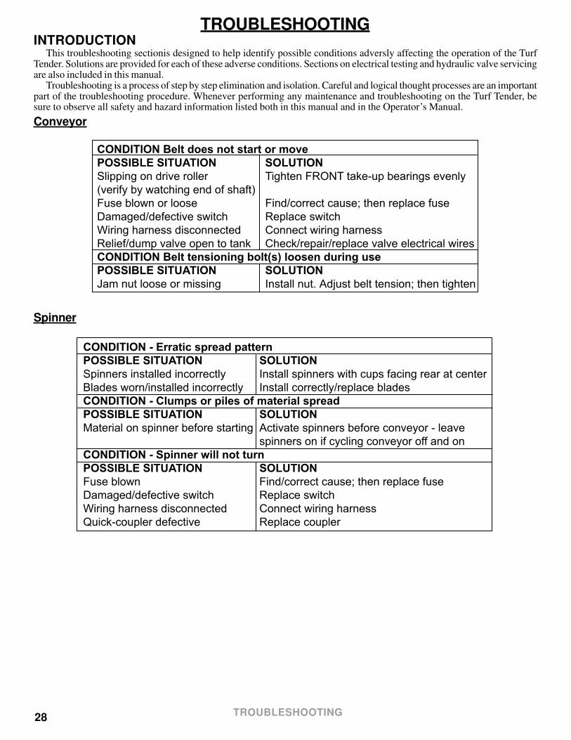
Conveyor
CONDITION Belt does not start or movePOSSIBLE SITUATION SOLUTIONSlipping on drive roller Tighten FRONT take-up bearings evenly(verify by watching end of shaft)Fuse blown or loose Find/correct cause; then replace fuseDamaged/defective switch Replace switchWiring harness disconnected Connect wiring harnessRelief/dump valve open to tank Check/repair/replace valve electrical wiresCONDITION Belt tensioning bolt(s) loosen during usePOSSIBLE SITUATION SOLUTIONJam nut loose or missing Install nut. Adjust belt tension; then tighten
Spinner
CONDITION - Erratic spread patternPOSSIBLE SITUATION SOLUTIONSpinners installed incorrectly Install spinners with cups facing rear at centerBlades worn/installed incorrectly Install correctly/replace bladesCONDITION - Clumps or piles of material spreadPOSSIBLE SITUATION SOLUTIONMaterial on spinner before starting Activate spinners before conveyor - leave spinners on if cycling conveyor off and onCONDITION - Spinner will not turnPOSSIBLE SITUATION SOLUTIONFuse blown Find/correct cause; then replace fuseDamaged/defective switch Replace switchWiring harness disconnected Connect wiring harnessQuick-coupler defective Replace coupler
TROUBLESHOOTING

29
Hydraulic System
CONDITION - Nothing WorksPOSSIBLE SITUATION SOLUTIONHydraulic valve not engaged Engage valve to full detent1 or more quick couplers not Fully couple all couplerscompletely coupled.Defective quick coupler(s) Replace defective quick coupler(s)Hydraulic fluid low Add hydraulic fluidCONDITION - Slow or jerky operationPOSSIBLE SITUATION SOLUTIONCold hydraulic oil Run engine and cycle hydraulicsLow hydraulic oil Check for leaks; add oilTractor flow control set too low Increase flow controlEngine speed too slow Increase engine speedFlow checking/faulty quick-coupler Replace couplerDrive motor damaged/defective Service/replace drive motorCONDITION - Conveyor/spinners operate backwardsPOSSIBLE SITUATION SOLUTIONHoses connected backwards Reverse connectionsMain hydraulic valve is in reverse Reverse valve directionCONDITION - Conveyor/spinners operate too slowlyPOSSIBLE SITUATION SOLUTIONValve adusted incorrectly Adjust valveInadequate hydraulic flow Check the gpm of your system.Orbital motor defective Service/replace motor.Valve not opening fully Service/replace valveCONDITION - Oil leaksPOSSIBLE SITUATION SOLUTIONLoose connections Tighten fittings (do not use Teflon tape)Damaged hose/fittings Replace hose/fittingsDamaged fittings/drive motor O-rings Replace with correct O-ringsCONDITION - Oil overheats or entire system fails to functionPOSSIBLE SITUATION SOLUTIONLow oil supply Add oilPlugged filter Replace filterInternal leak Call DealerPlugged suction screen Clean screenCONDITION - Orbital motor stallsPOSSIBLE SITUATION SOLUTIONShaft bearing damaged/defective Replace bearingConveyor binding/overloaded Reduce load; check for obstructionsOrbital motor damaged/defective Service/replace motor.Dump valve not opening Service/replace valve
TROUBLESHOOTING
30
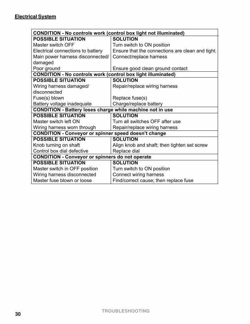
Electrical System
CONDITION - No controls work (control box light not illuminated)POSSIBLE SITUATION SOLUTIONMaster switch OFF Turn switch to ON positionElectrical connections to battery Ensure that the connections are clean and tight.Main power harness disconnected/ Connect/replace harnessdamagedPoor ground Ensure good clean ground contactCONDITION - No controls work (control box light illuminated)POSSIBLE SITUATION SOLUTIONWiring harness damaged/ Repair/replace wiring harnessdisconnectedFuse(s) blown Replace fuse(s)Battery voltage inadequate Charge/replace batteryCONDITION - Battery loses charge while machine not in usePOSSIBLE SITUATION SOLUTIONMaster switch left ON Turn all switches OFF after useWiring harness worn through Repair/replace wiring harnessCONDITION - Conveyor or spinner speed doesn’t changePOSSIBLE SITUATION SOLUTIONKnob turning on shaft Align knob and shaft; then tighten set screwControl box dial defective Replace dialCONDITION - Conveyor or spinners do not operatePOSSIBLE SITUATION SOLUTIONMaster switch in OFF position Turn switch to ON positionWiring harness disconnected Connect wiring harnessMaster fuse blown or loose Find/correct cause; then replace fuse
TROUBLESHOOTING
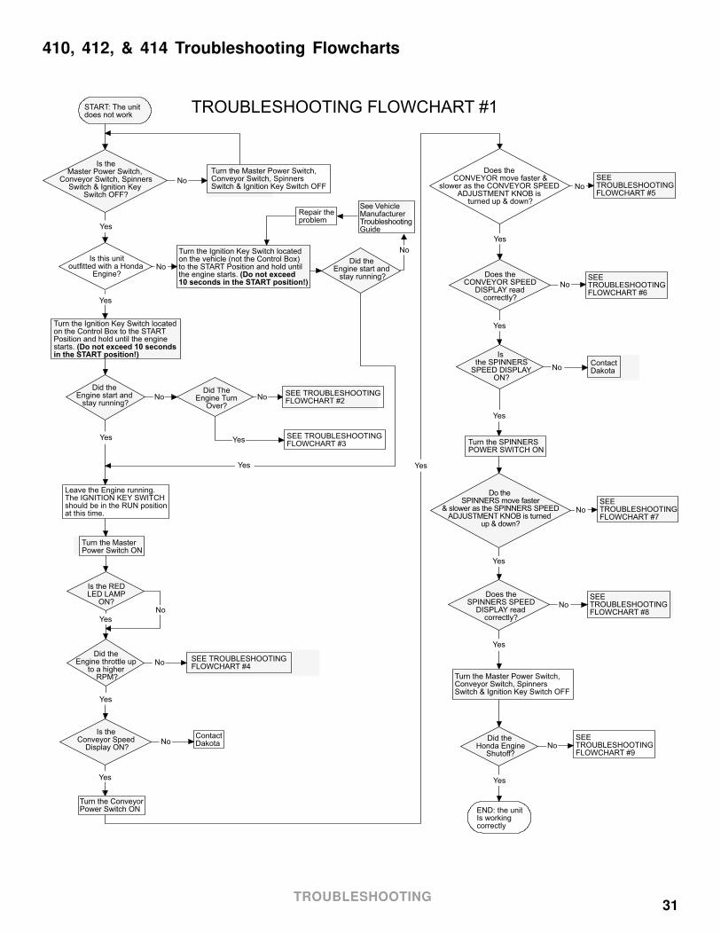
31
410, 412, & 414 Troubleshooting Flowcharts
START: The unitdoes not work
Turn the MasterPower Switch ON
Is theMaster Power Switch,
Conveyor Switch, SpinnersSwitch & Ignition Key
Switch OFF?
Turn the Master Power Switch, Conveyor Switch, SpinnersSwitch & Ignition Key Switch OFF
Is this unitoutfitted with a Honda
Engine?
Turn the Ignition Key Switch located on the Control Box to the START Position and hold until the engine starts. (Do not exceed 10 secondsin the START position!)
Turn the Ignition Key Switch located on the vehicle (not the Control Box) to the START Position and hold until the engine starts. (Do not exceed10 seconds in the START position!)
Did the Engine start and
stay running?
See Vehicle ManufacturerTroubleshootingGuide
Repair theproblem
No
Did the Engine start and
stay running?
Did TheEngine Turn
Over?
SEE TROUBLESHOOTINGFLOWCHART #2
SEE TROUBLESHOOTINGFLOWCHART #3
Leave the Engine running. The IGNITION KEY SWITCH should be in the RUN position at this time.
Is the REDLED LAMP
ON?
Did the Engine throttle up
to a higher RPM?
SEE TROUBLESHOOTINGFLOWCHART #4
Is the Conveyor Speed
Display ON?
ContactDakota
Turn the Conveyor Power Switch ON
SEE TROUBLESHOOTINGFLOWCHART #6
SEE TROUBLESHOOTINGFLOWCHART #5
Does the CONVEYOR move faster &
slower as the CONVEYOR SPEED ADJUSTMENT KNOB is
turned up & down?
Does theCONVEYOR SPEED
DISPLAY readcorrectly?
Is the SPINNERS
SPEED DISPLAYON?
ContactDakota
Turn the SPINNERSPOWER SWITCH ON
SEE TROUBLESHOOTINGFLOWCHART #7
SEE TROUBLESHOOTINGFLOWCHART #8
Do the SPINNERS move faster
& slower as the SPINNERS SPEED ADJUSTMENT KNOB is turned
up & down?
Does theSPINNERS SPEED
DISPLAY readcorrectly?
Turn the Master Power Switch, Conveyor Switch, SpinnersSwitch & Ignition Key Switch OFF
Did the Honda Engine
Shutoff?
SEE TROUBLESHOOTINGFLOWCHART #9
END: the unitIs workingcorrectly
Yes
Yes
Yes Yes
Yes
Yes
Yes
Yes
Yes
Yes
Yes
Yes
Yes
Yes
Yes
No
No
No No
No
No
No
No
No
No
No
No
No
TROUBLESHOOTING FLOWCHART #1
TROUBLESHOOTING

32
TROUBLESHOOTING FLOWCHART #2START: Continuedfrom TroubleshootingFlowchart #1
Did theEngine turn
over?
Check mainPower CableINLINE FUSE
MAIN INLINEFuse OK?
END: Continuetroubleshootingfrom FLOWCHART #1
Does the Fuse keepblowing after replacing
it during this troubleshootingflowchart usage?
Replace Fuse withone of exact typeand rating
Does the Fusekeep blowing?
ContactDakota
ReplacePOWER CABLE
Check FUSE "F2" inthe Rear Control Box on the Circuit Board
Check FUSE "F1" inthe Rear Control Box on the Circuit Board
"F1" FuseOK?
"F2" FuseOK?
Does the Fuse keepblowing after replacing
it during this troubleshootingflowchart usage?
Does the Fuse keepblowing after replacing
it during this troubleshootingflowchart usage?
Check FUSE "F3" inthe Rear Control Box on the Circuit Board
"F3" FuseOK?
Does the Fuse keepblowing after replacing
it during this troubleshootingflowchart usage?
Check the MAINBATTERY Voltage
Charge/replaceMAIN BATTERY
Is theMAIN BATTERY
Voltage OK?(12 to 14 VDC)
Check ALL Cablesand Connectors fordamage andproper fit
Check ALL Cablesand Connectors fordamage andproper fit
Cables andConnectors
OK?
Make properconnectionsand/or replacedamaged ones
Check Voltage onSTARTER WIREcoming from theRear Control Box
Is Voltagepresent on STARTER WIRE
coming from the Rear Control Box when the IGNITION KEY
SWITCH is held on?
Honda EngineSTARTER couldbe defective
Test or repairHonda EngineSTARTER
Test or replaceSTARTER RELAY"CR1" located in theRear Control Box
Does theEngine turn
over?
ContactDakota
ContactDakota
Check the PowerCable + Wire and -Wire connected tothe Main Battery
Is the Power Cable +Wire and - Wireconnected to theMain Battery in
reverse?
Connect the + Wire tothe + Terminal and the- Wire to the - terminalon the Main Battery
Disconnect MAIN POWER CABLEfrom the RearControl Box
Check STARTERWIRE and connectors for damage/short
WIRE andconnectors
OK?
Make properconnectionsand/or replacedamaged ones
Honda EngineSTARTER couldbe defective
ContactDakota
Yes
Yes
Yes Yes
YesYes
Yes
Yes
Yes
Yes
Yes
Yes
Yes
Yes
No No
No
NoNo
No
No
No
No
No
No
No
Yes
No
No
No
No No
Yes
TROUBLESHOOTING

33
��
START: Continuedfrom troubleshootingFlowchart #1
Did theEngine turn
over?
END: Continuetroubleshootingfrom FLOWCHART #1
Test/replace ENGINESHUTDOWN RELAY"CR3" located in theRear Control Box
Did the Enginestart and stay
running?
TROUBLESHOOTING FLOWCHART #3
Check ENGINESHUTDOWN WIREand connectors fordamage
Is the Wire and Connectors
OK?
Repair/replacedamagedWires/CableAssembly
Try startingthe Engine
Did the Enginestart and stay
running?
See Honda EngineTroubleshootingGuide for Enginenot starting
Test the ENGINE SHUTDOWNWIRE. The wire should read less than 5 ohms to ground when the IGNITION KEY SWITCH is in the OFF position and read as an openwhen in the RUN position.
Doesthe Wire test
correctly?
Repair/replacedamagedWires/CableAssembly
If the ENGINE SHUTDOWNWIRE can not be fixed to pass the test, send unit in for repair
No
No
Yes
Yes
Yes
Yes
Yes
No
No
No
TROUBLESHOOTING

34
START: Continued fromTroubleshootingFLOWCHART #1
Did the enginethrottle up to a higher RPM?
END: ContinueTroubleshooting from FLOWCHART #1
Check FUSE "F2" inthe rear enclosureon the circuit board
Fuse OK?Replace Fuse with one of exact type and rating
Does Fuse keepblowing after replacing
it during this troubleshootingflowchart usage?
Test HIGH RPMSOLENOID for linkage binding and/or short circuit
Is the HIGH RPM SOLENOID
OK?
Repair/ReplaceHIGH RPM SOLENOID
TROUBLESHOOTING FLOWCHART #4
Check HIGH RPMSOLENOID WIREand connectors fordamage
Is the HIGH RPM SOLENOID WIRE
and connectors OK?
Repair/replace HIGH RPM SOLENOID WIREAnd/Or Connectors
Check Voltage on HIGHRPM SOLENOID WIREcoming from the RearControl Box
Is Voltage present on HIGH RPM SOLENOID WIRE
coming from the Rear Control Box when the MASTER POWER
SWITCH is ON?
Test/replaceHIGH RPM RELAY"CR2" located in theRear Control Box
Does the Engine throttle up to a
higher RPM?
Contact Dakota
Contact Dakota
No
Yes
Yes
Yes
No
No
No
No
Yes
Yes
Yes
No No
Yes
TROUBLESHOOTING
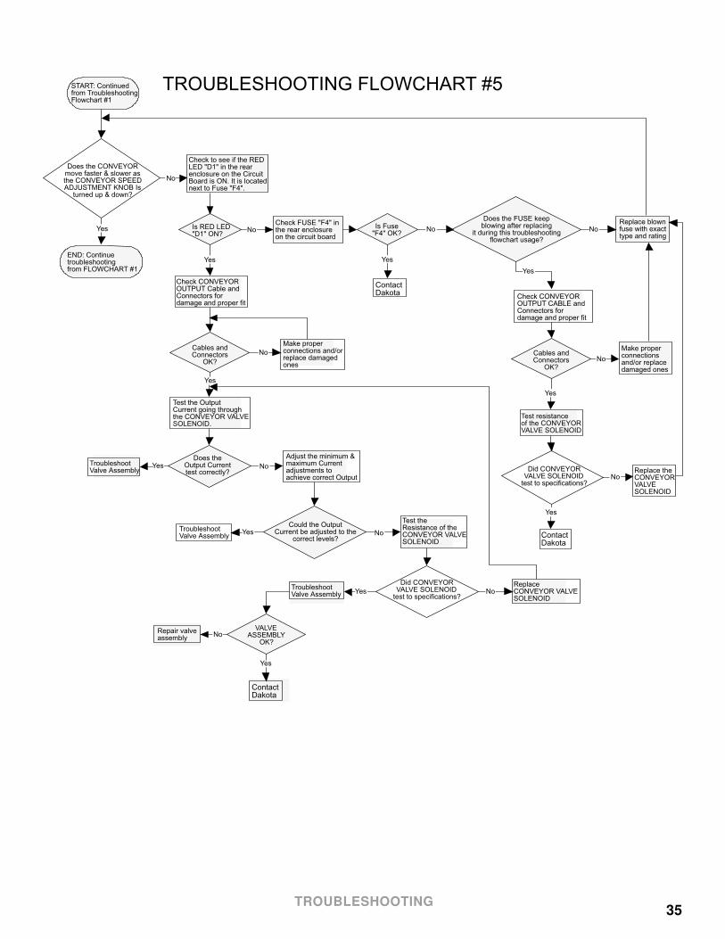
35
TROUBLESHOOTING FLOWCHART #5START: Continuedfrom TroubleshootingFlowchart #1
Check to see if the REDLED "D1" in the rearenclosure on the CircuitBoard is ON. It is locatednext to Fuse "F4".
Is RED LED"D1" ON?
Replace blownfuse with exact type and rating
Check CONVEYOROUTPUT CABLE andConnectors fordamage and proper fit
Cables andConnectors
OK?
Make properconnections and/orreplace damagedones
Test the OutputCurrent going throughthe CONVEYOR VALVESOLENOID.
Does the CONVEYORmove faster & slower asthe CONVEYOR SPEEDADJUSTMENT KNOB Is
turned up & down?
END: Continuetroubleshootingfrom FLOWCHART #1
Does the FUSE keepblowing after replacing
it during this troubleshootingflowchart usage?
Check FUSE "F4" inthe rear enclosureon the circuit board
Is Fuse"F4" OK?
Does theOutput Currenttest correctly?
Adjust the minimum &maximum Currentadjustments toachieve correct Output
Could the OutputCurrent be adjusted to the
correct levels?
Test theResistance of theCONVEYOR VALVESOLENOID
Did CONVEYORVALVE SOLENOID
test to specifications?
ReplaceCONVEYOR VALVESOLENOID
TroubleshootValve Assembly
TroubleshootValve Assembly
TroubleshootValve Assembly
VALVEASSEMBLY
OK?
ContactDakota
Repair valveassembly
ContactDakota
Check CONVEYOROUTPUT Cable andConnectors fordamage and proper fit
Cables andConnectors
OK?
Make properconnectionsand/or replace damaged ones
Test resistanceof the CONVEYOR VALVE SOLENOID
Did CONVEYORVALVE SOLENOID
test to specifications?
Replace theCONVEYOR VALVESOLENOID
ContactDakota
Yes
Yes
Yes
Yes
Yes
Yes
Yes
Yes
Yes
Yes
Yes
No
No
No
No
No
No
No
No
No
No No
TROUBLESHOOTING
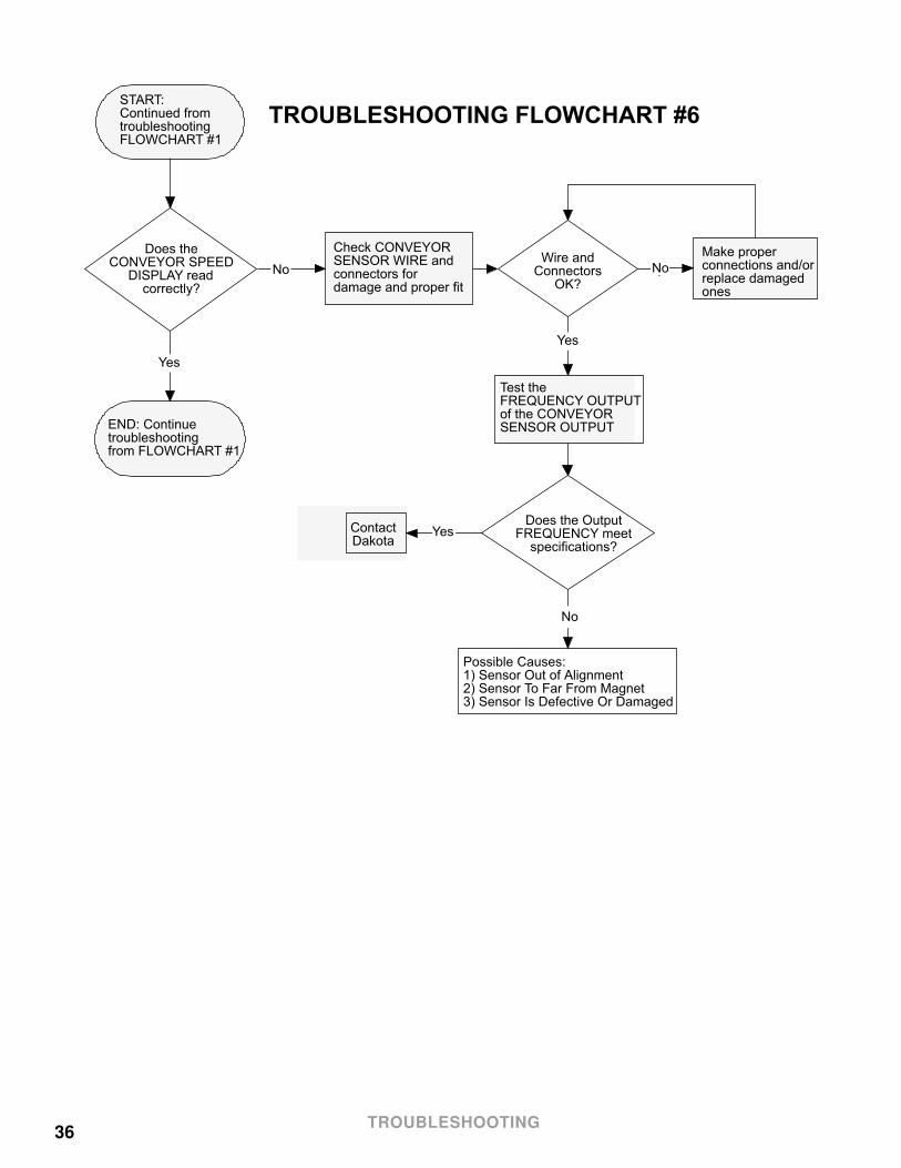
36
��
START: Continued fromtroubleshootingFLOWCHART #1
Does theCONVEYOR SPEED
DISPLAY readcorrectly?
END: Continuetroubleshootingfrom FLOWCHART #1
ContactDakota
Check CONVEYORSENSOR WIRE andconnectors fordamage and proper fit
Wire andConnectors
OK?
Test theFREQUENCY OUTPUTof the CONVEYORSENSOR OUTPUT
Does the OutputFREQUENCY meet
specifications?
Make properconnections and/orreplace damagedones
Possible Causes:1) Sensor Out of Alignment2) Sensor To Far From Magnet3) Sensor Is Defective Or Damaged
TROUBLESHOOTING FLOWCHART #6
Yes
No No
No
Yes
Yes
TROUBLESHOOTING
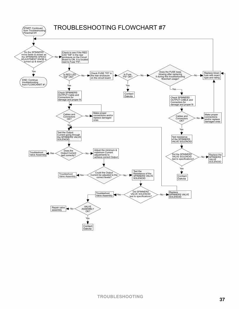
37
TROUBLESHOOTING FLOWCHART #7START: Continuedfrom TroubleshootingFlowchart #1
Check to see if the REDLED "D8" in the rearenclosure on the CircuitBoard is ON. It is locatednext to Fuse "F5".
Is RED LED"D8" ON?
Replace blownfuse with exact type and rating
Check SPINNERSOUTPUT CABLE andConnectors fordamage and proper fit
Cables andConnectors
OK?
Make properconnections and/orreplace damagedones
Test the OutputCurrent going throughthe SPINNERS VALVESOLENOID.
Do the SPINNERSmove faster & slower asthe SPINNERS SPEEDADJUSTMENT KNOB Is
turned up & down?
END: Continuetroubleshootingfrom FLOWCHART #1
Does the FUSE keepblowing after replacing
it during this troubleshootingflowchart usage?
Check FUSE "F5" inthe rear enclosureon the circuit board
Is Fuse"F5" OK?
Does theOutput Currenttest correctly?
Adjust the minimum &maximum Currentadjustments toachieve correct Output
Could the OutputCurrent be adjusted to the
correct levels?
Test theResistance of theSPINNERS VALVESOLENOID
Did SPINNERSVALVE SOLENOID
test to specifications?
ReplaceSPINNERS VALVESOLENOID
TroubleshootValve Assembly
TroubleshootValve Assembly
TroubleshootValve Assembly
VALVEASSEMBLY
OK?
ContactDakota
Repair valveassembly
ContactDakota
Check SPINNERSOUTPUT Cable andConnectors fordamage and proper fit
Cables andConnectors
OK?
Make properconnectionsand/or replace damaged ones
Test resistanceof the SPINNERS VALVE SOLENOID
Did the SPINNERSVALVE SOLENOIDtest to specifications?
Replace theSPINNERS VALVESOLENOID
ContactDakota
Yes
Yes
Yes
Yes
Yes
Yes
Yes
Yes
Yes
Yes
Yes
No
No
No
No
No
No
No
No
No
No No
TROUBLESHOOTING

38
��
START: Continued fromtroubleshootingFLOWCHART #1
Does theSPINNERS SPEED
DISPLAY readcorrectly?
END: Continuetroubleshootingfrom FLOWCHART #1
ContactDakota
Check SPINNERSSENSOR WIRE andconnectors fordamage and proper fit
Wire andConnectors
OK?
Test theFREQUENCY OUTPUTof the SPINNERSSENSOR OUTPUT
Does the OutputFREQUENCY meet
specifications?
Make properconnections and/orreplace damagedones
Possible Causes:1) Sensor Out of Alignment2) Sensor To Far From Magnet3) Sensor Is Defective Or Damaged
TROUBLESHOOTING FLOWCHART #8
Yes
No No
No
Yes
Yes
TROUBLESHOOTING
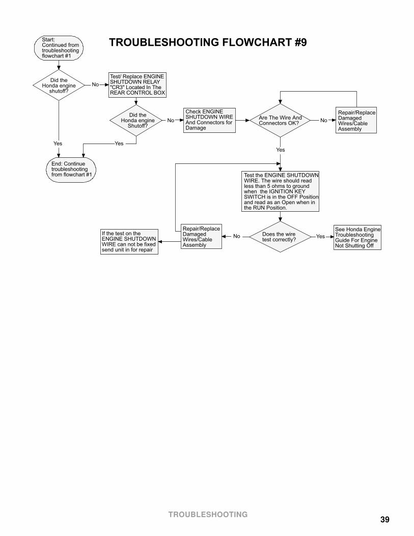
39
TROUBLESHOOTING FLOWCHART #9Start: Continued fromtroubleshootingflowchart #1
Did theHonda engine
shutoff?
End: Continuetroubleshootingfrom flowchart #1
Test/ Replace ENGINESHUTDOWN RELAY"CR3" Located In TheREAR CONTROL BOX
Check ENGINESHUTDOWN WIREAnd Connectors forDamage
Are The Wire AndConnectors OK?
Repair/ReplaceDamagedWires/CableAssembly
See Honda EngineTroubleshootingGuide For EngineNot Shutting Off
Does the wiretest correctly?
Repair/ReplaceDamagedWires/CableAssembly
Test the ENGINE SHUTDOWNWIRE. The wire should read less than 5 ohms to ground when the IGNITION KEYSWITCH is in the OFF Positionand read as an Open when inthe RUN Position.
If the test on theENGINE SHUTDOWNWIRE can not be fixedsend unit in for repair
Did theHonda engine
Shutoff?
Yes
Yes Yes
No
No No
No
Yes
TROUBLESHOOTING

40