


Languages
Pages
Legal

1
Table of contents……………………… P.1 Programming options……………… P.12
Introduction……………………………… P.2 Idle Mode………………………………. P.14
What’s included?……………………… P.2 Secure lock…………………………… P.14
Before you get Started.……………. P.3 Swap Start……………………………. P.14
Installation Points to Remember. P.3 Priority door access……………… P.14
AS-1515 features……………………. P.4 Starter disable……………………… P.15
Programmable Features…………….. P.5 Aux 2 output…………………………. P.16
Harness Description……..………….. P.7 Trunk output…………………………. P.17
Wiring Schematic………………………. P.9 Ground output………………………. P.18
2nd Ign / acc / crank relay output. P.10 Home valet………………………….. P.18
Programming transmitter…………. P.10 Multi-car operation……………….. P.18
Transmitter function………………… P.11 Resetting the module…………….. P.18
Valet operation………………………… P.11 Testing………………………………….. P.19
TACH learning…………………………… P.12 Closing up……………………………… P.19
Warranty……………………………….. P.20
Rev 2.02 LaGp – Nov/30/01 Manufactured in Canada by AUTOSTART
Installation Guide Table of Contents
NOTICE:
DUE TO THE POTENTIAL FOR DAMAGE TO THE VEHICLE, THE MANUFACTURER IS NOT RESPONSIBLE
FOR ANY ELECTRICAL OR MECHANICAL DAMAGE TO THE VEHICLE OR TO THE UNIT THAT HAS
CAUSED VEHICLE DAMAGE DUE TO IMPROPER INSTALLATION OF THE PRODUCT.
THIS UNIT MUST BE INSTALLED BY AN AUTHORIZED AUTOSTART TRAINED TECHNICIAN USING ALL
SAFETY DEVICES SUPPLIED. Please review the installation guide carefully before any work begins.
WARNING
THIS UNIT IS FOR AUTOMATIC TRANSMISSION ONLY, BEFORE INSTALLING THE UNIT TEST THAT THE
VEHICLE WILL NOT START IF THE GEAR SELECT LEVER IS IN A DRIVE POSITION. IF IT STARTS IN
GEAR, INSTALL A MANUAL TRANSMISSION CAR STARTER.
2
INTRODUCTION
The AS-1515 is the brainchild of over 2-year of research, development and dedication. With over 12 years of experience to feed from, our product development team was faced with the difficult task of creating a full-featured high-end remote starter system. The AS-1515 was to maintain low cost, while still offer all the great features that are only available on very expensive products, without compromising our solid reputation for quality, cost and reliability.
The result would excel far beyond what we had imagined; the feature filled AS-1515 has met every criterion for quality, and reliability. With the addition of over 15 new features, this product will satisfy any demand for high-end systems, and standard features.
After installing the system, we hope you too will agree that the new AS-1515 SH is a breakthrough in vehicle convenience technology, and remote starter systems.
WHAT IS INCLUDED
Please review the installation guide before beginning the installation, particularly the installation
schematic and the programming options.
It is very important that you familiarize yourself with the programming and the operation of the AS-1515 system, even if you have already installed an Autostart system in the past. There are many great new features that may be overlooked if the manual is not read, therefore not maximizing the potential of the AS-1515.
Prior to the installation be sure that all the hardware components required to install the system are in the box.
- The following is a list of components included in the kit:
• AS-1515 Control unit
• Plug-in push button valet
• Super-Heterodyne Receiver
• 5 button Multi channel transmitter
• SH interconnect cable
• Plug-in 2volt L.E.D
• Hood switch
Kit should also include the following:
• 6 pin main ignition harness
• 5 pin secondary harness
• 12 pin accessories harness
• Users guide and Installation manual
• 2 pin harness

3
BEFORE YOU GET STARTED…
WARNING! This unit is for AUTOMATIC TRANSMISSION ONLY! Before installing the unit test that the vehicle will not start if the gear select lever is in a drive position. If the vehicle starts in gear with the key, have the OEM neutral safety switch replaced before you install the car starter.NOTE: If the vehicle ONLY starts in gear by jumping the starter wire, but NOT WITH THE KEY,
than a neutral safety relay MUST be installed. (See troubleshooting Section – Vehicle starts in gear!)
FCC USER NOTICE:
THE MANUFACTURER IS NOT RESPONSIBLE FOR ANY RADIO OR TV INTERFERENCE CAUSED BY UNAUTHORIZED MODIFICATIONS TO THIS EQUIPMENT. SUCH MODIFICATIONS COULD VOID THE USER’S AUTHORITY TO OPERATE THE EQUIPMENT.
INSTALLATION POINTS TO REMEMBER
• When working on a vehicle always leave a window open.
• NEVER leave the keys in the car. Leave them on a workbench!
• Remove courtesy light fuse if possible to prevent battery drain.
• Inspect vehicle for any body damage or electrical problems.
• Make sure that all the switches and controls operate properly.
• Verify that the vehicle starts and idles properly.
• Never Install control unit where it could interfere with normal operation or obstruct service technicians.
• Do not disconnect the battery on vehicles equipped with air bags and anti-theft radios.
• Always use a grommet when running wires into the engine compartment. Never run wires through bare or sharp metal.
• Always solder and tape all connections.
• Never ground control unit to vehicle steering column.
• Make sure that vehicles equipped with automatic transmission do not start while in any of the drive
gears. (If it will start in gear please install a manual transmission starter)

4
AS-1515 - FEATURES LIST
• LONG RANGE SUPER HETERODYNE RECEIVER
• DRIVERS DOOR PRIORITY
• HOME VALET MODE• PROGRAMMABLE HIGH CURRENT SECOND IGNITION / ACCESSORIES / STARTER
OUTPUT
• SAFE START (2 button start operation.)
• SWAP START (2 button start operation)
• DOME LIGHT SUPERVISION*
• PROGRAMMING BUTTON (Makes programming a snap!!)
• INTELLIGENT FACTORY ALARM CONTROL (Can arm virtually any factory alarm!!)
• SECURE LOCK AND ARM
• 5 BUTTON, 10 CHANNEL REMOTE TRANSMITTER
• INDEPENDENT ARM / DISARM WIRES
• PANIC MODE. **
• MULTI-CAR OPERATION (Can control 2 separate Autostart equipped cars.)
• REMOTE WINDOW OR SUNROOF CLOSURE CAPABILITY ***
• CONTROLLABLE LATCHED 30 SEC NEGATIVE OUTPUT.
• PLUG IN PUSH BUTTON VALET SWITCH AND L.E.D
• PLUG IN CONNECTOR FOR VATS AND PASS LOCK BYPASS UNITS
• DIAGNOSTICS VIA PARKING LIGHT
• DUAL 12 VOLT SUPPLY
• OEM ALARM CONTROL
• NEGATIVE DOOR LOCK OUTPUTS
• IGNITION CONTROLLED DOOR LOCKS
• INTELLIGENT TACH WIRE LOCATOR (Tell you when you get the right Tach wire!!!)
• PAGER READY
• HEADLIGHT ILLUMINATION CONTROL. *
• PROGRAMMABLE PASSIVE OR ACTIVE ANTI-THEFT STARTER KILL OUTPUT
• ANTI-GRIND FEATURE *
• NEGATIVE TRUNK RELEASE OUTPUT
• EXTERNAL TRIGGER CONTROL
• CODE LEARNING TRANSMITTER
• USER CONTROLLED COLD WEATHER TIMER
• MULTI SPEED TACH LEARNING FOR HIGH/LOW SPEED TACH SIGNALS.
• PROGRAMMABLE RUN TIME (4,15 OR 25 Minutes)
• GROUNDOUT (CONSTANT)
• PROGRAMMABLE DOOR LOCK PULSE DURATION. (3/4, 4, or DBL Pulse)
• IDLE MODE
• GAS OR DIESEL OPERATION
• LIMITED LIFE WARRANTY. ****
NB: * Relay required.
** High current flasher relay required.
*** External window module may be required.
**** See Limited Life Warranty for details

5
PROGRAMMABLE FEATURES
The AS-1515 was designed with flexibility and OEM integration in mind. The 1515 give installers the output flexibility that every great installer is looking for; this unit can be customized and used in almost every possible application.With the integration of Timed / Latched, or ON/OFF outputs, this unit can single-handed control virtually any electrical system in the car!
The programmable features information is as follows:
• IGNITION CONTROLLED DOOR LOCKS
- ON by default, this feature will LOCK all the vehicles doors the first time the driver presses on the brake pedal after the vehicles had been started. The unit will UNLOCK all doors when the key is turned to the OFF position.
• SECURE LOCK
- OFF by default, this feature can control certain OEM factory alarm systems without connecting any other wires for the OEM alarm disarm. Some OEM systems use the factory Lock wire to ARM the alarm, and use the Unlock wire to disarm. Secure Lock will (when activated) upon receipt of a remote start signal, will unlock the doors (disarming the factory alarm) then 1 sec after remote start will RE-LOCK the doors. Most OEM systems, with the exception of VW will NOT rearm the alarm with the engine running, but WILL lock the doors. After shut down Secure Lock will RE-LOCK all the vehicles doors and ARM the alarm.
• PASSIVE OR ACTIVE STARTER KILL OUTPUT
- Passive with a 1min timeout be default, the starter interrupt output on this unit can be set Active,
(Will NOT arm itself) or it can be left Passive with a 1 min timeout, or Passive with a 3 min timeout.
• LOCK PULSE DURATION
- ¾ sec LOCK and ¾ sec Unlock pulses by default, this system can be programmed to give 4sec
lock /unlock outputs. (Used to control vacuum door lock system i.e.: Mercedes) Or for a single 1/4sec LOCK pulse and TWO-¼ sec UNLOCK pulses. (Used for double pulse disarm/unlock systems i.e.: Maxima, Pathfinder, Volks…)
• SAFE START (Child safety mode)
- OFF by default. When programmed this feature will require that the user press the start button on the remote transmitter 2 times within 3 sec. to start the vehicle. This will eliminate accidental remote starts, when the kids are entertaining the transmitter.
• SWAP START (OFF by Default)
AS-1515 has a new programmable OPTION, which is the SWAP START in MODE 2- FUNCTION 1 OPTION 3. This 2-button start feature is added for extra security and helps avoid accidentally starting the vehicle by remote. If the SWAP START is enable, AUX 2 becomes the START button.
• REMOTE START RUN TIME
- The AS-1515 can be programmed to run the engine for 4 / 15 / 25 minutes in Gas mode, and 9 / 20
/ 30 minutes in Diesel mode. Standard default run time is 15 minutes in Gas mode, and 20 minutes in Diesel mode.
• IDLE MODE
- On by default, this great standard feature allows the user to remove the keys and let the vehicle idle for the pre-programmed run time. To enable idle mode simple press on the START button on the transmitter with the engine running, and then remove the key. (The vehicle will continue to run)
6
• VEHICLE TYPE – GAS OR DIESEL
- In Gas mode by default, the unit can be programmed to operate in Diesel mode. In Diesel mode the system will wait for glow plug light to go out for up to 30 seconds, before cranking the engine.Note that the run time is automatically extended when Diesel mode is selected.
• HOME VALET MODE- OFF by default. This amazing safety feature will allow the user to remotely place the system into a
no start mode, so if the vehicle is parked indoors there is no danger of the vehicle starting on it’s own. To activate Home Valet Mode the user has simply to press on the LOCK or UNLOCK button and within 3 seconds press on the STOP button. Once activated the vehicle will not start by remote until the key is turned to the ignition position.
• AUX 2 – REMOTE OR TIME CONTROLLED OUTPUT
- The auxiliary 2 output can be used for many different applications. The output can be programmed to give continuous output + 1second, when remote Lock & Unlock are pressed simultaneously. Or it can be toggled ON and OFF with a 30second timeout, or toggle ON & OFF with a 60 second timeout. This means that when the buttons are pressed AUX 2 will output ground for 30 or 60 seconds or until the buttons are pressed again to shut off the output. This feature can be used to control a siren (PANIC MODE) or it can turn on the headlights (HEADLIGHT ILLUMINATION) the timer can also roll up the windows on some vehicles without any external window module. (Volks, BMW, ect.)
• AUX 3 – TRUNK OUT or SUN ROOF CONTROL
- The auxiliary 3 output from the AS-1515 can be programmed to operate as a trunk release (1-sec pulse when channel 3 is pressed.) Or it can be programmed to operate as a constant while pressed signal. The system is set to operate as a trunk release by default.
7
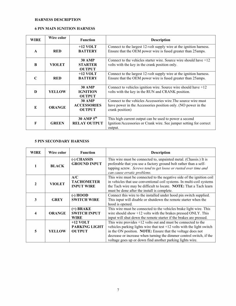
HARNESS DESCRIPTION
6 PIN MAIN IGNITION HARNESS
WIREWire color
Function Description
A RED
+12 VOLT
BATTERY
Connect to the largest 12-volt supply wire at the ignition harness.Ensure that the OEM power wire is fused greater than 25amps.
B VIOLET
30 AMP
STARTER
OUTPUT
Connect to the vehicles starter wire. Source wire should have +12 volts with the key in the crank position only.
C RED
+12 VOLT
BATTERY
Connect to the largest 12-volt supply wire at the ignition harness.Ensure that the OEM power wire is fused greater than 25amps.
D YELLOW
30 AMP
IGNITION
OUTPUT
Connect to vehicles ignition wire. Source wire should have +12 volts with the key in the RUN and CRANK position.
E ORANGE
30 AMP
ACCESSORIES
OUTPUT
Connect to the vehicles Accessories wire.The source wire must have power in the Accessories position only. (NO power in the crank position)
F GREEN
30 AMP 5th
RELAY OUTPUT
This high current output can be used to power a second Ignition/Accessories or Crank wire. See jumper setting for correct output.
5 PIN SECONDARY HARNESS
WIRE Wire color Function Description
1 BLACK
(-) CHASSIS
GROUND INPUT
This wire must be connected to, unpainted metal. (Chassis.) It is preferable that you use a factory ground bolt rather than a self-tapping screw. Screws tend to get loose or rusted over time and can cause erratic problems.
2 VIOLET
A/C
TACHOMETER
INPUT WIRE
This wire must be connected to the negative side of the ignition coil in vehicles that use conventional coil systems. In multi-coil systems the Tach wire may be difficult to locate. NOTE: That a Tach learn must be done after the install is complete.
3 GREY
(-) HOOD
SWITCH WIRE
Connect this wire to the installed under hood pin switch supplied. This input will disable or shutdown the remote starter when the hood is opened.
4 ORANGE
(+) BRAKE
SWITCH INPUT
WIRE
This wire must be connected to the vehicles brake light wire. This wire should show +12 volts with the brakes pressed ONLY. This input will shut down the remote starter if the brakes are pressed.
5 YELLOW
+12 VOLT
PARKING LIGHT
OUTPUT
This wire provides +12 volts out and must be connected to the vehicles parking lights wire that test +12 volts with the light switch in the ON position. NOTE: Ensure that the voltage does not decrease or increase when turning the dimmer control switch, if the voltage goes up or down find another parking lights wire.

8
12 PIN-ACCESSORIES HARNESS
WireWire color
Function Description
6 BLUE TRUNK or AUX 3
(-)
(500mA) Negative output. This output can be used to control the trunk release (1sec. pulse) or can be set to operate as a Constant as long as channel 3 is help pressed. (For sun roof or window close)
7 BROWN LOCK (-) Programmable 500mA, ¾ sec – 4 sec – negative output.
8 GREEN UNLOCK (-) Programmable 500mA, ¾ sec – 4 sec – or DBL pulse negative output.
9WHITE /
BROWNARM (-)
MAX 500mA ground signal when the doors are locked by remote. This wire will go to ground ¼ sec before the lock pulse, and go off 1/8 sec after Lock. Must be connected to the OEM Arm wire (Usually dome light) NOTE: System will also give RE-ARM pulse after remote start shutdown on this wire.
10WHITE /
GREENDISARM (-)
Max 500mA, 1sec ground pulse when the doors are unlocked by remote. Connect to vehicles OEM disarm wire. NOTE: System will also give Disarm pulse before remote start on this wire.
11
BLUE /
WHITE
AUX 1 (-)
PRIORITY
DOOR ACCESS
This output will provide a 1 sec negative output when the UNLOCK button on the transmitter is pressed a second time. Can be used as Priority door access or a trunk release.
12
WHITE /
ORANGE
(-) STARTER
KILL (ARMED
OUTPUT)
This wire will provide a constant 500mA. Output when the system is ARMED (Locked by remote) Can be connected to external starter interrupt relay.
13 ORANGE AUX 2
PANIC MODE
Negative 500mA. Output. Can be programmed for any one of the following three options. (1) Constant while LOCK+UNLOCK are pressed + 1 sec after
release of buttons. (2) LOCK+UNLOCK Toggles ON/OFF (Max.30 sec) (3) LOCK+UNLOCK Toggles ON/OFF (Max.60 sec)
14 VIOLET
EXTERNAL
TRIGGER INPUT
This input will start the vehicle when it receives a 1-second ground pulse from an external pager system or timer module. And will shut down with a 1sec. Pulse when running by remote.
15 WHITE
(-) GROUND-
OUTPUT
500mA. constant ground output when running. Will become active before remote ignition ON, and stay active until 4 sec after system shutdown.
16 N/A N/A THIS PORT IS NOT USED, LEAVE EMPTY.
17 YELLOW GLOW-PLUG
INPUT (+)
This positive input will monitor the glow plug light in DIESEL mode, and will wait until the glow plug light goes out to crank the vehicle. Connect to the positive when ON side of the glow plug light in the vehicle.
2 PIN HARNESS
WIRE COLOR FUNCTION DESCRIPTION
18BLUE/WHI
TEN/A N/A
19 YELLOW (-) PARKING
LIGHTNegative 500 mA output.

9

10
2nd
IGN / ACC / CRANK RELAY OUTPUT
The AS-1515 series car starters are equipped with a high current, programmable 5th relay onboard that can be used to power a second ignition, accessory, or crank wire.The unit uses a series of 3 jumpers; each jumper represents a function. In order to activate any one of the three possible 2nd outputs, you must place the jumper, (supplied) on one of the three pins and simply connect the 14awg wire to the vehicles second ign/acc/crank wire. NOTE: ONLY ONE OF THE THREE JUMPERS CAN BE USED AT ONE TIME.
NOTE: The relay output rating on this unit is 25-amp max output. Defective OEM solenoid switches can sometimes draw up to 50 or 60 amp, causing the 30-amp blow. Check starter wire for voltage draw when vehicle is cranking with a digital voltmeter.
PROGRAMMING A TRANSMITTER
The AS-1515’s transmitter does not come pre-programmed and must be code learned after the wiring of the module is complete. The system has the ability to learn up to 4 different transmitters, if a fifth transmitter is learned the first transmitter in memory will be lost. To erase all transmitters from memory you must perform a module reset. To program a new transmitter do the following.
1. Ensure the ignition is OFF
• Hold hood switch down for 4 seconds.
• Release pin-switch (parking lights should come ON)
• With parking lights ON, immediately push and release pin-switch again. Parking lights will
stay on for up to 20 seconds
2. Turn the ignition key ON, OFF, ON, OFF (Parking lights should go OFF when key is turned ON
the first time) (NOTE: L.E.D should be flashing for the next step)
3. Press transmitter LOCK TWICE, within 5 seconds of step 2. (NOTE: Parking lights will flash 5
times quick and then stay ON and system returns to programming mode.)
4. To exit, close the hood.
*NOTE: L.E.D follows parking lights in all modes.
NOTE: The system can hold a maximum of 4 transmitters in memory
11
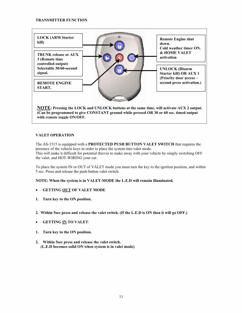
TRANSMITTER FUNCTION
VALET OPERATION
The AS-1515 is equipped with a PROTECTED PUSH BUTTON VALET SWITCH that requires the presence of the vehicle keys in order to place the system into valet mode. This will make it difficult for potential thieves to make away with your vehicle by simply switching OFF the valet, and HOT-WIRING your car.
To place the system IN or OUT of VALET mode you must turn the key to the ignition position, and within 5 sec. Press and release the push button valet switch.
NOTE: When the system is in VALET-MODE the L.E.D will remain illuminated.
• GETTING OUT OF VALET MODE
1. Turn key to the ON position.
2. Within 5sec press and release the valet switch. (If the L.E.D is ON then it will go OFF.)
• GETTING IN TO VALET:
1. Turn key to the ON position.
2. Within 5sec press and release the valet switch.
(L.E.D becomes solid ON when system is in valet mode)
Remote Engine shut
down.
Cold weather timer ON.
& HOME VALET
activation
UNLOCK (Disarm
Starter kill) OR AUX 1
(Priority door access –
second press activation.)
LOCK (ARM Starter
kill)
TRUNK release or AUX
3 (Remote time
controlled output)
Selectable 30/60-second
signal.
REMOTE ENGINE
START.
NOTE: Pressing the LOCK and UNLOCK buttons at the same time, will activate AUX 2 output.
(Can be programmed to give CONSTANT ground while pressed OR 30 or 60 sec. timed output
with remote toggle ON/OFF.

12
MULTI-SPEED TACH LEARNING
The AS-1515 system is designed to read High or Low speed TACH signals that are being produced from newer ignition systems. (Chrysler, Dodge & Plymouth.)
TACH adjustment procedures should be done every time a new unit is installed. This is because
the Tach signal from some ignition systems can sometimes be too high or too low, thus causing failed starts under different temperatures.
The procedures for Multi-Speed TACH Adjustment are as follows:
• Ensure that the IGNITION switch is turned “OFF”
1. Hold hood switch down for 4 seconds. 2. Release pin-switch (Parking lights should come “ON”) 3. With parking lights ON, immediately push and release pin-switch again. (Parking lights will stay
ON for up to 20 seconds)4. Hold brake pedal and Press the LOCK+UNLOCK buttons simultaneously on the transmitter
(Parking lights flash 4 times)5. Release the brakes and start the vehicle, allow it to reach regular engine idle speed. (Parking
lights will go out when TACH is detected)
6. Press and release the brake pedal.7. If parking lights flash 5 times the Tach signal has been learned.
NOTE: To end TACH learning at any time, close hood.
PROGRAMMING OPTIONS
The AS-1515 System, is equipped with 3 custom programming menus that allow the user to custom fit the systems outputs according to the installation requirements. These options are designed to help make interfacing with all vehicles possible.
To get into custom programming mode you must do the following:
* Ensure that the IGNITION is turned OFF
1. Hold pin-switch down for 4 sec. 2. Release pin-switch (parking lights will come ON) 3. Immediately push and release pin-switch once again. (Parking lights will stay ON for 20 sec.) 4. Press and hold brakes, and select LOCK, UNLOCK or TRUNK on remote transmitter. (LOCK for
mode one, UNLOCK for mode two, and TRUNK for mode three.) Lights will flash once for mode 1, twice for mode 2, and three times for mode3.
5. Release the brakes.
*Once you’ve entered one of the three programming menus you can release the brake pedal.
NOTE: The unit will stay in programming mode until the hood pin-switch is pressed or the valet switch has been turned off. (So take your time to make the proper selection)
The menu will automatically start you at function one. Once you choose from one of the three Options, you will automatically advance to the next function.
To select one of the three options press the appropriate transmitter button. (See below)
1. LOCK = Option 1
2. UNLOCK = Option 2
3. TRUNK = Option 3
* See Transmitter Function on page.11 for button layout.
Once an option has been selected the parking lights will flash 1, 2 or 3 times. (Depending on option selected)

13
MODE 1 *INDICATES DEFAULT SETTING
FUNCTION 1 – Ignition Controlled door locks
OPTION 1* Ignition Lock ENABLED
OPTION 2 Ignition Lock DISABLED
FUNCTION 2 – Secure Lock
OPTION 1* Secure Lock DISABLED (1 Sec Disarm pulse.)
OPTION 2 Secure Lock ENABLED OPTION 3 Secure Lock DISABLED (0.5 Sec Disarm pulse)
FUNCTION 3 – Passive/Active Starter Kill Mode
OPTION 1* Starter Kill PASSIVE (1 Minute timeout.)
OPTION 2 Starter Kill ACTIVE OPTION 3 Starter Kill PASSIVE (3 Minute timeout.)
FUNCTION 4 – Door Lock Timing
OPTION 1* 3/4 second LOCK / UNLOCK pulses.
OPTION 2 4 second LOCK / UNLOCK pulses. OPTION 3 Single ¾ second LOCK pulse, and TWO - ¼ second UNLOCK pulses.
MODE 2 * INDICATES DEFAULT SETTING
FUNCTION 1 – Safe Start Mode
OPTION 1 SAFE START - ENABLED OPTION 2* SAFE START – DISABLED
OPTION 3 SWAP START: To START: press LOCK + UNLOCK buttons simultaneously. AUX 2: press START button
FUNCTION 2 – Engine Run Time
OPTION 1 Run time - 4 minute in Gas mode / 9 minutes Diesel mode. OPTION 2* Run time - 15 minute in Gas mode / 20 minutes Diesel mode.OPTION 3 Run time - 25 minute in Gas mode / 30 minutes Diesel mode.
FUNCTION 3 – Idle Mode
OPTION 1 IDLE MODE - DISABLEDOPTION 2* IDLE MODE - ENABLED-
FUNCTION 4 – Gas or Diesel Mode
OPTION 1 GASOLINE Engine Mode OPTION 2* GASOLINE Engine Mode
OPTION 3 DIESEL Engine Mode.
MODE 3 * INDICATES DEFAULT SETTING
FUNCTION 1 – Home Valet Mode
OPTION 1 HOME VALET - ENABLED OPTION 2* HOME VALET - DISABLED
FUNCTION 2 – Trunk / AUX 3
OPTION 1 CONSTANT WHILE TRUNK BUTTON PRESSED OPTION 2* 1 Sec. OUTPUT WHILE TRUNK BUTTON PRESSED
OPTION 3 (Data out for future use)

14
FUNCTION 3 – Timer output / AUX 2
OPTION 1 CONSTANT WHILE PRESSED (LOCK & UNLOCK pressed simultaneously)
OPTION 2* TOGGLE ON / TOGGLE OFF up to 30 second timeout.
OPTION 3 TOGGLE ON / TOGGLE OFF up to 60 second timeout
IDLE MODE
When programmed, this option allows the user to engage the remote starter to take over the vehicle while it is already running. This option will keep the vehicle running for the pre-programmed run time or until shut down by remote control.
To activate Idle Mode you must do the following:
1. With vehicle running press LOCK, UNLOCK or START on the transmitter until the parking lights come ON.
2. Remove the key and exit the vehicle. 3. Lock doors - Vehicle will stay running for the entire pre-programmed run time.
SECURE LOCK
OFF by default. When programmed, SECURE LOCK adds an UNLOCK pulse when start signal from transmitter is received. It will provide a LOCK pulse 1 seconds after the module starts the engine, and a LOCK pulse 4 seconds after it stops the engine.
SWAP START (OFF by Default)
AS-1515 has a new programmable OPTION, which is the SWAP START in MODE 2- FUNCTION 1 OPTION 3. This 2-button start feature is added for extra security and helps to avoid accidentally starting the vehicle by remote. To START the car just press LOCK + UNLOCK buttons simultaneously.
PRIORITY DOOR ACCESS
This great feature will allow the user to unlock only the drivers door with a single press of the transmitter unlock button, and then unlock the rest of the vehicles doors with a second press of the unlock button if desired. This output will provide a 1 sec negative output when the UNLOCK button on the transmitter is pressed a second time. Can be used as PRIORITY DOOR ENTRY or even TRUNK release.
NOTE: On vehicles that are factory equipped with Priority Door Access, all the required relays are already in the vehicle. (I.e.: Caravan) In this case the vehicle will have 3 OEM relays for door locks, one relay will UNLOCK just the drivers door, the second relay will UNLOCK the rest of the doors and the third OEM relay will LOCK all doors. To connect to this type of system, simply identify the relays and locate the trigger pins, (Pins 85 or 86) and connect the GREEN Unlock output from the starter to the OEM drivers door unlock relay, and the BLUE / WHITE from the starter to the Second Unlock relay.

15
To install PRIORITY DOOR ENTRY on 2 relay OEM systems, follow the diagram below.
*The OEM UNLOCK wire at the driver’s door actuator must be cut in half, and a relay must be installed.
NOTE: The relay must be activated with the GREEN (-) Unlock output from the remote starter, and the BLUE / WHITE wire from the module must be connected to the OEM negative UNLOCK wire before the door lock switch in the vehicle.
STARTER DISABLE
The AS-1515 is equipped with a selectable PASSIVE or ACTIVE arming STARTER DISABLE circuit that will immobilize the vehicle when the system is armed. This wire will provide a constant 500mA. Negative output when the system is ARMED (Locked by remote) can be connected to external starter or ignition interrupt relay. (See diag.)
The STARTER DISABLE circuit can be programmed for PASSIVE mode, (Arms itself) with a 1 minute or 3 minute timeout. Or it can also be programmed for ACTIVE mode. (Must be armed by user)
NOTE: Installation of STARTER DISABLE system requires an external relay. (NOT INCLUDED!)
*When installing a starter kill, it is extremely important that pin 86 gets wired to ignition and that it does
not get jumped to pin 30 (damage to vehicle could result).

16
AUX 2 – PANIC MODE TIMED OUTPUT
This 500mA. negative auxiliary 2 output, can be used for many different applications. The output can be programmed to give continuous output + 1second, when remote Lock & Unlock are pressed simultaneously. Or it can be toggled ON and OFF with a 30second timeout, or toggle ON & OFF with a 60 second timeout. This means that when the buttons are pressed AUX 2 will output ground for 30 or 60 seconds or until the buttons are pressed again to shut off the output. This feature can be used as PANIC MODE, HEADLIGHT ILLUMINATION, and REMOTE DOME LIGHT SUPERVISION. Or the timer can also roll up the windows on some vehicles without any external window module. (Volks, BMW, ect.)
The following diagrams show how to use this output for PANIC MODE, HEADLIGHT ILLUMINATION or REMOTE DOME LIGHT SUPERVISION.
PANIC MODE
NOTE: Flasher relay required
HEADLIGHT ILLUMINATION
REMOTE ACTIVATED DOME LIGHT SUPERVISION

17
POSITIVE TRIGGER NEGATIVE TRIGGER
AUX 3 – TRUNK OR CONSTANT WHILE PRESSED
This 500mA. Negative auxiliary 3 output, can be used for many different applications. The output can be programmed to give a 1sec pulse, or a continuous output for as long as trunk is held. (For Sunroof or Window close)NOTE: If Aux 3 is programmed for a 1 second trunk signal, you will need to press the TRUNK
button for 3 seconds in order to pop the trunk.
The following diagrams show how to use this output for Positive or Negative TRUNK release systems.
GROUND OUTPUT

18
500mA. constant ground output when running. Will become active before remote ignition ON, and stay active until 4 sec after system shutdown. Can be used to activate external relays, bypass kits or external module.
HOME VALET
This amazing safety feature will allow the user to remotely place the system into a no start mode, so if the vehicle is parked indoors there is no danger of the vehicle starting on it’s own. The activation of Home Valet Mode is a couple of transmitter away by the user. Simply press on the LOCK button and within 3 seconds press on the STOP button.
NOTE: Once activated the vehicle will not start by remote until the key is turned to the ignition
position.
TO ACTIVATE HOME VALET
Press the LOCK BUTTON on the transmitter
Press STOP BUTTON within 3 sec. on the transmitter until the lights flash twice quickly
TO DISABLE HOME VALET, TURN IGNITION TO THE “ON” POSITION
MULTI-CAR OPERATION
The AS-1515 systems feature Multi-Car operation. This allows the owner of two Autostart systems in two of his/her vehicles to control both systems with one transmitter. (Both vehicles must be equipped with an AS-1515.The remote transmitter of the primary vehicle can control the starter disable system, the door locks and the remote car starter operation of the second vehicle. The remote transmitter of the second vehicle can also operate the primary vehicle.
*To program transmitter to second vehicle for multi-car operation, you must press on the transmitters
TRUNK simultaneously in step 3 & 4 of transmitter code learning. (See above for Transmitter code learning)
RESETTING THE MODULE
The AS-1515 system is equipped with a reset function that allows the installer to erase all transmitter codes and return all programmed options to factory default.
To reset the module:
NOTE: System flashes parking lights 8 times upon reset.
• Ensure that the VALET & IGNITION are OFF.
1. Hold pin-switch down for 4 sec. 2. Release pins-witch 3. Immediately push and release pins-witch once again. 4. Press the VALET switch 5 times
NOTE: After a reset has been performed, the system sets all options back to default. (See programming
page for default option.)

19
TESTING
Before putting the vehicle back together, it’s a good idea to check that the system operates properly. The following test procedures should be used to verify proper installation and operation of the system. Before testing make sure all connections are soldered, and unit is plugged in.
1. Test the HOOD SWITCH shutdown: With the vehicle running under remote starter, open the hood, the vehicle should shutdown. If it does not shut off, check your hood switch and connector.
2. Test the BRAKE shutdown circuit: With the vehicle running under remote, press and release the brakes. The engine should shutdown immediately. If the engine continues to RUN check brake switch connection.
3. Test all FUNCTION for proper timing and operation
4. Remote start the engine and listen for starter drag. If the starter cranks too long perform another TACH learn.
CLOSING UP
Use tie wraps or screws to properly secure the starter module and keep the wiring away from any moving parts such as parking brakes or steering column shafts. Mount any switches in a good accessible location where they won’t get kicked or hit accidentally. Take the time to properly explain all functions and features to the customer before they leave the premises. Most comebacks are the result of misunderstandings about how a product works or performs. Doing this will save time and money. Always make all your connections before plugging in the module and be sure to test all functions properly before closing up the installation.

20
LIMITED LIFETIME WARRANTY
REMOTE STARTERS:
As the manufacturer, Autostart Inc. warrants to the original consumer purchaser only (NON TRANSFERABLE), that the remote starter module (control box) shall be free from defects in material and workmanship, for as long as the original consumer purchaser continuously owns the vehicle the remote starter was originally installed in, as specified below:
In all cases, the consumer must return the remote starter module to the point of purchase, and must provide an original proof of purchase to said retailer. A remote starter module will be returned to the retailer for the consumer to claim within a 4 (four)-week period. For case 3), a check in the amount of $35.00 must accompany the remote starter module, or the retailer may refuse the return.
ACCESSORIES:
Autostart Inc. warrants to the original consumer purchaser that it will replace any Autostart accessory part for a one-year period from date of purchase. Accessories include all items that are not remote starter modules (such as transmitters, sirens, LED, switch, etc.). Accessories will only be replaced if proven defective in materials or workmanship, and if, when returned to point of purchase, the retailer is provided with an original proof of purchase. The accessory will be returned to the retailer for the consumer to claim within a 4 (four)-week period. WARRANTY IS VOID IF:
) The product has been damaged, altered in any way, or tampered with, without the explicit written consent of an Autostart technician. For remote starter modules, this includes the opening or removal of the module’s plastic covering, or the removal or alteration of the barcode label on the module’s plastic covering. ) The product is damaged due to accident, fire, flood, shipping and handling, misuse, neglect, or other conditions beyond the control of Autostart. ) The product has been installed or repaired by anyone other than an authorized technician. ) The product has been improperly installed or used.
WARRANTY DOES NOT COVER:
) Batteries. ) Scratched or worn transmitter cases. ) Installation and/or removal charges for all remote starter modules and accessories.) Shipping and handling charges incurred for product exchange or replacement. ) Any material damages other than to the product itself.
THIS LIMITED LIFETIME WARRANTY SHALL CONSTITUTE THE SOLE LIABILITY OF AUTOSTART INC. FOR OUR PRODUCTS, AND IS IN LIEU OF ALL OTHER WARRANTIES, EXPRESS OR IMPLIED. THERE ARE NO WARRANTIES OF MERCHANTABILITY AND FITNESS FOR A PARTICULAR PURPOSE. NO PERSON, FIRM OR CORPORATION IS AUTHORIZED TO ASSUME FOR AUTOSTART INC. ANY OTHER LIABILITY WITH RESPECT TO THE SALE OR USE OF OUR PRODUCTS. AUTOSTART’S LIABILITY, WHETHER BASED ON CONTRACT, TORT, WARRANTY, STRICT LIABILITY, OR ANY OTHER THEORY, SHALL NOT EXCEED THE PRICE OF THE INDIVIDUAL UNIT WHOSE DEFECT FOR DAMAGE IS THE BASIS OF THE CLAIM. UNDER NO CIRCUMSTANCE WILL AUTOSTART INC., ITS DISTRIBUTORS, OR THEIR AGENTS BEAR ANY LIABILITY WHATSOEVER FOR INCIDENTAL OR CONSEQUENTIAL DAMAGES.
Top Related