** WARNING ** WARNING ** WARNING ** …* WARNING ** WARNING ** WARNING ** WARNING ** This document...
262
** WARNING ** WARNING ** WARNING ** WARNING ** This document is intended for informational purposes only. Users are cautioned that California Department of Transportation (Department) does not assume any liability or responsibility based on these electronic files or for any defective or incomplete copying, exerpting, scanning, faxing or downloading of the contract documents. As always, for the official paper versions of the bidders packages and non-bidder packages, including addenda write to the California Department of Transportation, Plans and Bid Documents, Room 0200, P.O. Box 942874, Sacramento, CA 94272-0001, telephone (916) 654-4490 or fax (916) 654-7028. Office hours are 7:30 a.m. to 4:15 p.m. When ordering bidder or non-bidder packages it is important that you include a telephone number and fax number, P.O. Box and street address so that you can receive addenda.
Transcript of ** WARNING ** WARNING ** WARNING ** …* WARNING ** WARNING ** WARNING ** WARNING ** This document...
** WARNING ** WARNING ** WARNING ** WARNING **This document is intended for informational purposes only.
Users are cautioned that California Department of Transportation (Department) does not assume any liability orresponsibility based on these electronic files or for any defective or incomplete copying, exerpting, scanning, faxing ordownloading of the contract documents. As always, for the official paper versions of the bidders packages and non-bidderpackages, including addenda write to the California Department of Transportation, Plans and Bid Documents, Room 0200,P.O. Box 942874, Sacramento, CA 94272-0001, telephone (916) 654-4490 or fax (916) 654-7028. Office hours are 7:30a.m. to 4:15 p.m. When ordering bidder or non-bidder packages it is important that you include a telephone number and faxnumber, P.O. Box and street address so that you can receive addenda.

etric
Caltrans
STATE OF CALIFORNIA
DEPARTMENT OF TRANSPORTATION__________________________________________________________
NOTICE TO CONTRACTORSAND
SPECIAL PROVISIONSFOR CONSTRUCTION ON STATE HIGHWAY IN
THE CITY AND COUNTY OF SAN FRANCISCO
AT YERBA BUENA ISLAND
DISTRICT 04, ROUTE 80
__________________________________________________________
For Use in Connection with Standard Specifications Dated JULY 1999, Standard Plans Dated JULY 1999, and LaborSurcharge and Equipment Rental Rates.
__________________________________________________________
(INFORMAL BIDS CONTRACT)CONTRACT NO. 04-0120E4
04-SF-80-13.4,13.8
ACBRIM-080-(094)N
Bids Open: December 16, 2003Dated: October 17, 2003 OSD
*************************************************************************************************
IMPORTANTSPECIAL NOTICES
*************************************************************************************************
ACCESS TO PROJECT SITEProspective bidders may make arrangements to visit the project site by contacting the Duty Senior, District 04 Office,
111 Grand Avenue, Oakland, CA 94612, email: [email protected], telephone number (510) 286-5209.
ALTERNATIVE BIDS
This project provides for alternative bids for foreign and domestic steel and iron materials, as provided in 23 CFR635.410(b)(3). The bidder's attention is directed to "Alternative Bids," "Award and Execution of Contract," and "BuyAmerica Requirements" of the special provisions.
A+B BIDDING:
The bidder's attention is directed to Section 2, "Proposal Requirements and Conditions," Section 3, "Award andExecution of Contract," and Section 4, "Beginning of Work, Time of Completion and Liquidated Damages," in the specialprovisions. In addition to the item prices and totals, the proposal shall set forth the number of working days bid to completethe work on the contract. Bids will be compared on the basis of the sum of the item totals on the Engineer's Estimate for thework to be done (TOTAL BID (A)), plus the product of the number of working days bid to complete all work and the costper day shown on the Engineer's Estimate (TOTAL BID (B)). The lowest bid will be determined on the basis of the "TotalBasis for Comparison of Bids (A+B)" set forth in the Engineer's Estimate.
Bids in which the number of working days bid for completion of the work exceed the maximum number of daysspecified will be considered non-responsive and will be rejected.
DBE ASSISTANCE:
Effective September 2, 2003, Triaxial Management Services will no longer provide lists of certified DBEs to contractorsbidding on projects or provide DBEs with assistance in preparing bids for subcontracting or supplying materials. Triaxialprovided these services for contracts in Districts 01, 02, 03, 04, 05 (except San Luis Obispo and Santa Barbara Counties), 06(except Kern County), 09 and 10.
Contractors bidding on projects in these Districts may obtain lists of certified DBEs from the Department's Website athttp://www.dot.ca.gov/hq/bep. The Department also publishes a quarterly directory of certified firms that may be orderedfrom the Publications Unit at (916) 445-3520.
Special Provisions Section 2-1.02B "Submission of DBE Information" requires DBE information to be submitted on the'CALTRANS BIDDER-DBE INFORMATION' form included in the proposal. To meet the DBE goal or to establish thatgood faith efforts to meet the DBE goal have been made, bidders are reminded that DBE participation should be identifiedfor all items of work performed by DBE's. In this regard, bidders are reminded that utilization of DBE's may be reflected insuch bid items as "Establish Marine Access", "Mobilization" and "Time-related Overhead. The extent of DBE participationin such items of work may be credited towards the DBE contract goal.
SUBMISSION OF DBE INFORMATION:
Attention is directed to Section 2-1.02B, "Submission of DBE Information," of the special provisions, regardingsubmittal of the "CALTRANS BIDDER - DBE INFORMATION" form and GOOD FAITH EFFORT (GFE)DOCUMENTATION form.
ALL bidders shall complete the "CALTRANS BIDDER - DBE INFORMATION" form included in the Proposal andsubmit it WITH THE BID.
The apparent successful bidder (low bidder), the second low bidder and the third low bidder shall submit the GOODFAITH EFFORT (GFE) DOCUMENTATION form by THE FOURTH DAY following bid opening.
The bidder shall submit written confirmation from each DBE that the DBE is participating in the contract, and includethe confirmation with the submittal of the bid or submit it by the time specified for submittal of the GOOD FAITH EFFORT(GFE) DOCUMENTATION form.
FAILURE TO SUBMIT THE REQUIRED DBE INFORMATION AND THE GFE DOCUMENTATION, IFREQUIRED, BY THE TIMES SPECIFIED WILL BE GROUNDS FOR FINDING THE BID OR PROPOSALNONRESPONSIVE.
The provisions regarding the information and supporting documents the bidder should submit to establish the bidder'sgood faith efforts to meet the DBE goal, and the "DBE Information Good Faith Efforts" form in the Proposal, have beenenhanced for clarification.
CONTRACTORS AND DBE'S
In order to assure timely award of the contract, it is imperative that the apparent low bidder, second low bidder and thirdlow bidder, and their respecticve subcontractors and suppliers have personnel available during the award period to answerquestion relevant to DBE status and good faith effort attainment.
WORKING DAYS:
The definition of a working day has been re-defined for this project. (See Section 4 of these special provisions.)
The time limit specified in the special provisions for the completion of work contemplated herein is consideredinsufficient to permit completion of the work by the Contractor working a normal number of hours per day or week on asingle shift basis. It is expected that additional shifts will be required throughout the life of the contract to the extent deemednecessary to ensure that the work will be completed within the time limit specified. (See Section 4 of these specialprovisions.)
AWARD OF CONTRACT:
Attention is directed to Section 3, "Award and Execution of Contract," of the special provisions regarding the time inwhich the contract will be awarded.
SMALL BUSINESS AND DVBE REPORTING:
Attention is directed to Section 2-1.02C, "Small Business and Disabled Veterans Business Enterprise Utilization andReporting," of thespecial provisions.
MONITORING:
The bidder's attention is also directed to the monthly report required in Section 5-1.14, "Monitoring," of the specialprovisions. The monthly report will be made available to interested local agencies. A monthly forum will be conducted byCaltrans at which the report will be reviewed. The Contractor is required to attend the monthly forum and present themonthly report.
Contract No. 04-0120E4i
TABLE OF CONTENTSNOTICE TO CONTRACTORS ...........................................................................................................................................1COPY OF ENGINEER'S ESTIMATE.................................................................................................................................3SPECIAL PROVISIONS .....................................................................................................................................................7SECTION 1. SPECIFICATIONS AND PLANS ................................................................................................................7AMENDMENTS TO JULY 1999 STANDARD SPECIFICATIONS.................................................................................7SECTION 2. PROPOSAL REQUIREMENTS AND CONDITIONS ..............................................................................54
2-1.01 GENERAL ......................................................................................................................................................542-1.015 FEDERAL LOBBYING RESTRICTIONS ..................................................................................................542-1.02 DISADVANTAGED BUSINESS ENTERPRISE (DBE) ..............................................................................552-1.02A DBE GOAL FOR THIS PROJECT .............................................................................................................562-1.02B SUBMISSION OF DBE INFORMATION..................................................................................................572-1.02C SMALL BUSINESS AND DISABLED VETERAN BUSINESS ENTERPRISE UTILIZATION ANDREPORTING...............................................................................................................................................................582-1.03 ESCROW OF BID DOCUMENTATION ......................................................................................................592-1.04 ALTERNATIVE BIDS ...................................................................................................................................602-1.05 BIDDERS COMPENSATION .......................................................................................................................61
SECTION 3. AWARD AND EXECUTION OF CONTRACT ........................................................................................61SECTION 4. BEGINNING OF WORK, TIME OF COMPLETION AND LIQUIDATED DAMAGES........................62SECTION 5. GENERAL...................................................................................................................................................62SECTION 5-1. MISCELLANEOUS.................................................................................................................................62
5-1.01 WORKING DRAWINGS...............................................................................................................................62`5-1.0105 INTEGRATED SHOP DRAWINGS ........................................................................................................635-1.011 EXAMINATION OF PLANS, SPECIFICATIONS, CONTRACT, AND SITE OF WORK ......................655-1.012 DIFFERING SITE CONDITIONS ...............................................................................................................655-1.013 LINES AND GRADES.................................................................................................................................655-1.015 LABORATORY ...........................................................................................................................................655-1.017 CONTRACT BONDS...................................................................................................................................655-1.02 LABOR NONDISCRIMINATION ................................................................................................................655-1.022 PAYMENT OF WITHHELD FUNDS .........................................................................................................665-1.03 INTEREST ON PAYMENTS.........................................................................................................................665-1.031 FINAL PAYMENT AND CLAIMS.............................................................................................................665-1.04 PUBLIC SAFETY ..........................................................................................................................................675-1.05 TESTING ........................................................................................................................................................685-1.06 REMOVAL OF ASBESTOS AND HAZARDOUS SUBSTANCES ............................................................685-1.07 YEAR 2000 COMPLIANCE..........................................................................................................................685-1.075 BUY AMERICA REQUIREMENTS ...........................................................................................................685-1.08 SUBCONTRACTOR AND DBE RECORDS................................................................................................695-1.083 DBE CERTIFICATION STATUS................................................................................................................695-1.086 PERFORMANCE OF DBE SUBCONTRACTORS AND SUPPLIERS .....................................................695-1.09 SUBCONTRACTING ....................................................................................................................................705-1.10 PROMPT PROGRESS PAYMENT TO SUBCONTRACTORS ...................................................................705-1.102 PROMPT PAYMENT OF WITHHELD FUNDS TO SUBCONTRACTORS ............................................705-1.103 RECORDS ....................................................................................................................................................715-1.11 PARTNERING ...............................................................................................................................................715-1.114 CORRIDOR VALUE ANALYSIS...............................................................................................................715-1.12 PROJECT INFORMATION...........................................................................................................................72
INFORMATION HANDOUT .............................................................................................................................725-1.13 NON-JOURNEY PERSON TRAINING PROGRAM ...................................................................................745-1.14 MONITORING...............................................................................................................................................75
PROJECT SPECIAL FORMS .............................................................................................................................755-1.15 DISPUTE REVIEW BOARD.........................................................................................................................765-1.16 COST REDUCTION INCENTIVE PROPOSALS.........................................................................................875-1.17 TIDAL CONDITIONS AND ELEVATION DATUM ..................................................................................875-1.18 ELECTRONIC DAILY EXTRA WORK REPORT.......................................................................................87
Contract No. 04-0120E4ii
5-1.19 AREAS FOR CONTRACTOR'S USE ...........................................................................................................885-1.20 UTILITIES......................................................................................................................................................895-1.21 SANITARY PROVISIONS............................................................................................................................895-1.22 BRIDGE TOLLS ............................................................................................................................................895-1.23 PERMITS AND LICENSES...........................................................................................................................895-1.24 FORCE ACCOUNT PAYMENT ...................................................................................................................895-1.245 FOREIGN FABRICATION..........................................................................................................................905-1.25 PAYMENTS ...................................................................................................................................................905-1.26 SOUND CONTROL REQUIREMENTS .......................................................................................................915-1.27 PHOTO IDENTIFICATION SYSTEM..........................................................................................................915-1.28 ENVIRONMENTAL WORK RESTRICTIONS............................................................................................93
SPECIES OF CONCERN ....................................................................................................................................945-1.29 ENVIRONMENTALLY SENSITIVE AREAS (GENERAL) .......................................................................95
ARCHAEOLOGICAL ESA 1..............................................................................................................................96PAYMENT...........................................................................................................................................................96
5-1.30 RELATIONS WITH CALIFORNIA DEPARTMENT OF FISH AND GAME ............................................965-1.31 RELATIONS WITH REGIONAL WATER QUALITY CONTROL BOARD .............................................965-1.32 RELATIONS WITH U.S. ARMY CORPS OF ENGINEERS .......................................................................975-1.33 RELATIONS WITH SAN FRANCISCO BAY CONSERVATION DEVELOPMENT COMMISSION.....975-1.34 RELATIONS WITH UNITED STATES COAST GUARD ..........................................................................985-1.35 RELATIONS WITH UNITED STATES FISH AND WILDLIFE SERVICE...............................................995-1.36 RELATIONS WITH NATIONAL MARINE FISHERIES SERVICES ......................................................1005-1.37 DAMAGE BY STORM, FLOOD, TSUNAMI OR EARTHQUAKE..........................................................1005-1.38 INDEMNIFICATION...................................................................................................................................100
SECTION 6. (BLANK)...................................................................................................................................................101SECTION 7. (BLANK)...................................................................................................................................................101SECTION 8. MATERIALS.............................................................................................................................................101SECTION 8-1. MISCELLANEOUS...............................................................................................................................101
8-1.01 SUBSTITUTION OF NON-METRIC MATERIALS AND PRODUCTS...................................................1018-1.02 PREQUALIFIED AND TESTED SIGNING AND DELINEATION MATERIALS ..................................107
SECTION 8-2. CONCRETE...........................................................................................................................................1128-2.01 PORTLAND CEMENT CONCRETE ..........................................................................................................1128-2.02 CORROSION CONTROL FOR PORTLAND CEMENT CONCRETE......................................................1148-2.03 OPTIONAL MARINE-BASED PORTLAND CEMENT CONCRETE BATCH PLANT..........................115
SECTION 8-3. WELDING .............................................................................................................................................1168-3.01 WELDING....................................................................................................................................................116
GENERAL .........................................................................................................................................................116WELDING QUALITY CONTROL...................................................................................................................119PAYMENT.........................................................................................................................................................122
SECTION 8-4. STRUCTURAL STEEL.........................................................................................................................1228-4.01 STEEL AUDITS ...........................................................................................................................................122
SECTION 9. DESCRIPTION OF BRIDGE WORK ......................................................................................................123SECTION 10. CONSTRUCTION DETAILS.................................................................................................................123SECTION 10-1. GENERAL ...........................................................................................................................................123
10-1.01 ORDER OF WORK....................................................................................................................................12310-1.02 WATER POLLUTION CONTROL ...........................................................................................................123
RETENTION OF FUNDS .................................................................................................................................124STORM WATER POLLUTION PREVENTION PLAN PREPARATION, APPROVAL AND AMENDMENTS............................................................................................................................................................................125COST BREAK-DOWN .....................................................................................................................................126SWPPP IMPLEMENTATION...........................................................................................................................129MAINTENANCE...............................................................................................................................................130REPORTING REQUIREMENTS......................................................................................................................130SAMPLING AND ANALYTICAL REQUIREMENTS ...................................................................................131PAYMENT.........................................................................................................................................................132
10-1.03 TURBIDITY CONTROL ...........................................................................................................................133PAYMENT.........................................................................................................................................................135
10-1.04 NON-STORM WATER DISCHARGES....................................................................................................135
Contract No. 04-0120E4iii
MARINE EXCAVATION DEWATERING .....................................................................................................135INSPECTION.....................................................................................................................................................136SPILL CONTINGENCY ...................................................................................................................................136LIQUIDS, RESIDUES AND DEBRIS ..............................................................................................................136PAYMENT.........................................................................................................................................................136
10-1.05 TEMPORARY CONCRETE WASHOUT FACILITY ..............................................................................136MATERIALS .....................................................................................................................................................137INSTALLATION...............................................................................................................................................137MAINTENANCE...............................................................................................................................................138PAYMENT.........................................................................................................................................................138
10-1.06 COOPERATION.........................................................................................................................................13810-1.07 TRANSPORTATION FOR THE ENGINEER...........................................................................................13910-1.08 ESTABLISH MARINE ACCESS ..............................................................................................................14010-1.09 PROGRESS SCHEDULE (CRITICAL PATH METHOD) .......................................................................141
DEFINITIONS...................................................................................................................................................141GENERAL SCHEDULE ITEMS.......................................................................................................................143INTERIM BASELINE SCHEDULE .................................................................................................................144BASELINE SCHEDULE...................................................................................................................................144PROJECT SCHEDULE REPORTS...................................................................................................................145WEEKLY SCHEDULE MEETINGS ................................................................................................................146MONTHLY CASH FLOW REPORTS..............................................................................................................146MONTHLY UPDATE SCHEDULES ...............................................................................................................146SCHEDULE REVISIONS .................................................................................................................................147TIME IMPACT ANALYSIS .............................................................................................................................148FINAL SCHEDULE UPDATE..........................................................................................................................148EQUIPMENT AND SOFTWARE.....................................................................................................................148PAYMENT.........................................................................................................................................................149
10-1.10 TIME-RELATED OVERHEAD.................................................................................................................15010-1.11 WORKING DRAWING SUBMITTAL SCHEDULE ................................................................................15210-1.12 ELECTRONIC MOBILE DAILY DIARY SYSTEM DATA DELIVERY...............................................153
DATA CONTENT REQUIREMENTS .............................................................................................................153DATA DELIVERY REQUIREMENTS ............................................................................................................155
10-1.13 MOBILIZATION........................................................................................................................................15610-1.14 CONSTRUCTION SURVEYING..............................................................................................................157
PAYMENT.........................................................................................................................................................15810-1.15 CONSTRUCTION AREA TRAFFIC CONTROL DEVICES ...................................................................15810-1.16 CONSTRUCTION AREA SIGNS..............................................................................................................15910-1.17 MAINTAINING TRAFFIC ........................................................................................................................15910-1.18 CLOSURE REQUIREMENTS AND CONDITIONS................................................................................161
CLOSURE SCHEDULE....................................................................................................................................162CONTINGENCY PLAN....................................................................................................................................162LATE REOPENING OF CLOSURES...............................................................................................................162COMPENSATION.............................................................................................................................................162
10-1.19 TRAFFIC CONTROL SYSTEM FOR LANE CLOSURE ........................................................................16210-1.20 TEMPORARY CRASH CUSHION MODULE .........................................................................................16310-1.21 EXISTING HIGHWAY FACILITIES .......................................................................................................16410-1.22 EARTHWORK ...........................................................................................................................................164
TOWER OVERSIZED HOLES.........................................................................................................................164ISOLATION MATERIAL.................................................................................................................................165FOUNDATION TOLERANCES.......................................................................................................................165PAYMENT.........................................................................................................................................................166
10-1.23 DREDGING................................................................................................................................................166PAYMENT.........................................................................................................................................................172
10-1.24 PILING........................................................................................................................................................172GENERAL .........................................................................................................................................................172DRIVING EQUIPMENT...................................................................................................................................173PILE ALIGNMENT TEMPLATE AND PILE HANDLING SUBMITTAL ....................................................173DRIVING PILES ...............................................................................................................................................174
Contract No. 04-0120E4iv
PILE DRIVING REFUSAL...............................................................................................................................174PILE DRIVING LOW RESISTANCE ..............................................................................................................175PILE PENETRATION ACCEPTANCE............................................................................................................175DRIVING SYSTEM SUBMITTAL...................................................................................................................175DYNAMIC MONITORING ..............................................................................................................................178CAST-IN-DRILLED-HOLE CONCRETE PILES ............................................................................................178MATERIALS .....................................................................................................................................................179OPEN ENDED CAST-IN-STEEL-SHELL CONCRETE PILING ...................................................................188STEEL PIPE PILING.........................................................................................................................................189NONDESTRUCTIVE TESTING FOR STEEL PIPE PILING .........................................................................192MEASUREMENT AND PAYMENT (PILING)...............................................................................................192
10-1.25 MARINE PILE DRIVING ENERGY ATTENUATOR.............................................................................193GENERAL .........................................................................................................................................................194WORKING DRAWINGS ..................................................................................................................................195MEASUREMENT AND PAYMENT................................................................................................................195
10-1.26 CONCRETE STRUCTURES .....................................................................................................................196LIGHTWEIGHT CONCRETE ..........................................................................................................................196MASS CONCRETE...........................................................................................................................................197BOTTOM SLAB CONCRETE PLACEMENT .................................................................................................200FALSEWORK ...................................................................................................................................................202MEASUREMENT AND PAYMENT................................................................................................................202
10-1.27 NONSHRINK GROUT ..............................................................................................................................203DESCRIPTION..................................................................................................................................................203MATERIALS .....................................................................................................................................................203WORKING DRAWINGS ..................................................................................................................................203PLACEMENT....................................................................................................................................................203QUALITY CONTROL ......................................................................................................................................203MEASUREMENT AND PAYMENT................................................................................................................204
10-1.28 NONSHRINK FIBER-REINFORCED GROUT........................................................................................204DESCRIPTION..................................................................................................................................................204MATERIALS .....................................................................................................................................................204WORKING DRAWINGS ..................................................................................................................................205PLACEMENT....................................................................................................................................................205QUALITY CONTROL ......................................................................................................................................205MEASUREMENT AND PAYMENT................................................................................................................205
10-1.29 REINFORCEMENT ...................................................................................................................................206ULTIMATE BUTT SPLICES............................................................................................................................206EPOXY-COATED PREFABRICATED REINFORCEMENT .........................................................................209MEASUREMENT AND PAYMENT................................................................................................................211
10-1.30 HEADED BAR REINFORCEMENT.........................................................................................................211GENERAL .........................................................................................................................................................211PRODUCTION TESTS .....................................................................................................................................212MEASUREMENT AND PAYMENT................................................................................................................213
10-1.31 STEEL STRUCTURES ..............................................................................................................................213GENERAL .........................................................................................................................................................213WORKING DRAWINGS ..................................................................................................................................213ERECTION PLAN.............................................................................................................................................214MATERIALS .....................................................................................................................................................215THROUGH-THICKNESS QUALITY ..............................................................................................................215FABRICATION .................................................................................................................................................215SURFACE PREPARATION .............................................................................................................................217WELDING OF STEEL STRUCTURES............................................................................................................217SHOP WELDING..............................................................................................................................................217FIELD WELDING.............................................................................................................................................221FIELD WELDING OF PILE/SLEEVE CONNECTOR PLATES.....................................................................221MEASUREMENT AND PAYMENT................................................................................................................223
10-1.32 PLASTIC LUMBER...................................................................................................................................223WORKING DRAWINGS ..................................................................................................................................223
Contract No. 04-0120E4v
MATERIALS .....................................................................................................................................................224TESTING ...........................................................................................................................................................226CONSTRUCTION .............................................................................................................................................227MEASUREMENT AND PAYMENT................................................................................................................228
10-1.33 ULTRA HIGH MOLECULAR WEIGHT POLYETHYLENE PANEL....................................................228MATERIALS .....................................................................................................................................................228CONSTRUCTION .............................................................................................................................................228MEASUREMENT AND PAYMENT................................................................................................................228
10-1.34 CLEAN AND PAINT STRUCTURAL STEEL.........................................................................................229CLEANING .......................................................................................................................................................229PAINTING.........................................................................................................................................................229
10-1.35 MISCELLANEOUS METAL (BRIDGE) ..................................................................................................230NONSKID SURFACE.......................................................................................................................................230
10-1.36 CHAIN LINK FENCE................................................................................................................................23110-1.37 CONCRETE BARRIER (TYPE K)............................................................................................................231
SECTION 10-2. (BLANK)..............................................................................................................................................231SECTION 10-3. ELECTRICAL SYSTEMS...................................................................................................................231
10-3.01 DESCRIPTION...........................................................................................................................................23110-3.02 GROUNDING FOR PIERS E2 AND T1 FOUNDATIONS ......................................................................231
REFERENCES...................................................................................................................................................231SUBMITTALS...................................................................................................................................................232MATERIALS .....................................................................................................................................................232EXECUTION .....................................................................................................................................................232MEASUREMENT..............................................................................................................................................232
10-3.03 STRONG MOTION DETECTION DOWNHOLE ....................................................................................232MATERIAL .......................................................................................................................................................232EXECUTION .....................................................................................................................................................232MEASUREMENT..............................................................................................................................................232
10-3.04 NAVIGATION LIGHTING SYSTEM.......................................................................................................232SUBMITTALS...................................................................................................................................................232MATERIALS .....................................................................................................................................................233EXECUTION .....................................................................................................................................................233MEASUREMENT..............................................................................................................................................233
10-3.05 PILE CORROSION MONITORING SYSTEM........................................................................................233STANDARDS....................................................................................................................................................233SUBMITTALS...................................................................................................................................................234MEASUREMENT..............................................................................................................................................234
10-3.06 PAYMENT .................................................................................................................................................234SECTION 11. (BLANK).................................................................................................................................................235SECTION 12. (BLANK).................................................................................................................................................235SECTION 13. (BLANK).................................................................................................................................................235SECTION 14 FEDERAL REQUIREMENTS FOR FEDERAL-AID CONSTRUCTION PROJECTS.........................236
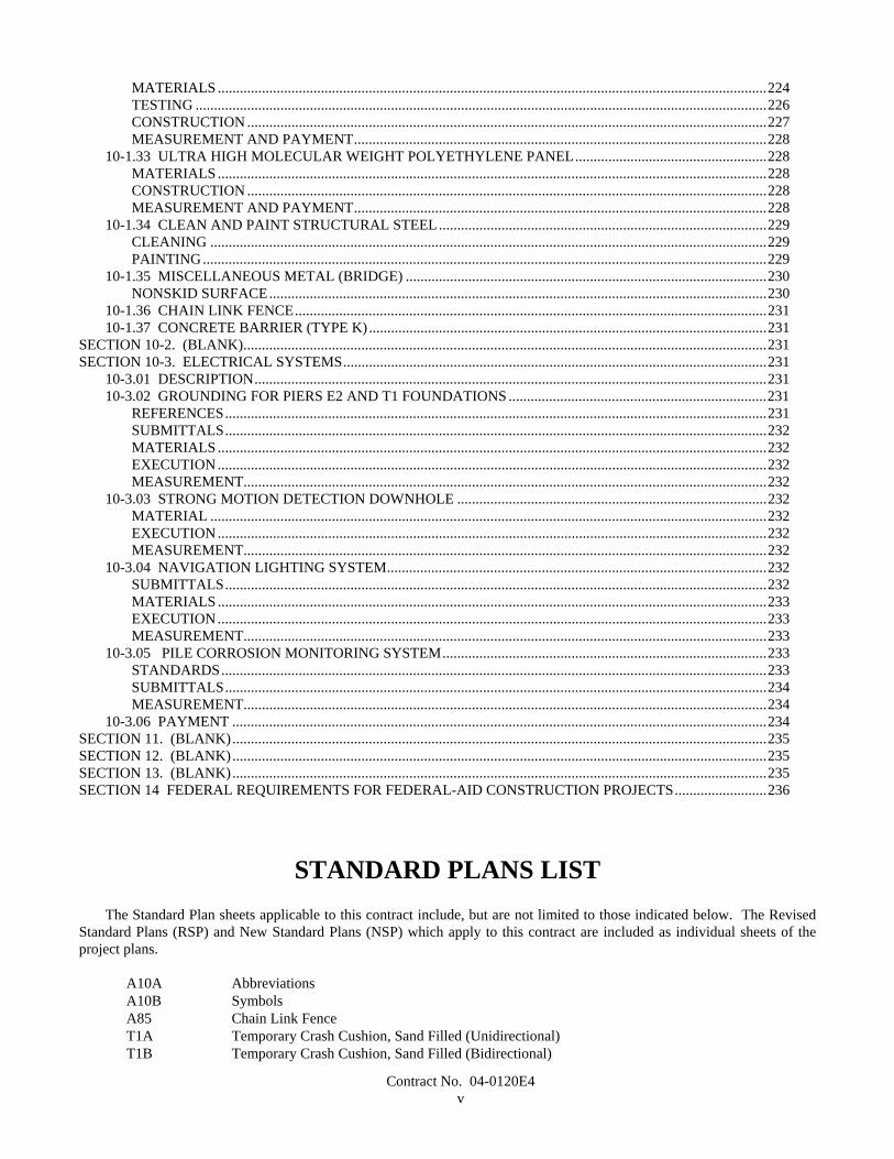
STANDARD PLANS LISTThe Standard Plan sheets applicable to this contract include, but are not limited to those indicated below. The Revised
Standard Plans (RSP) and New Standard Plans (NSP) which apply to this contract are included as individual sheets of theproject plans.
A10A AbbreviationsA10B SymbolsA85 Chain Link FenceT1A Temporary Crash Cushion, Sand Filled (Unidirectional)T1B Temporary Crash Cushion, Sand Filled (Bidirectional)

Contract No. 04-0120E4vi
T3 Temporary Railing (Type K)B7-5 Deck DrainsES-1A Signal, Lighting and Electrical Systems - Symbols and AbbreviationsES-1B Signal, Lighting and Electrical Systems - Symbols and Abbreviations
Contract No. 04-0120E41
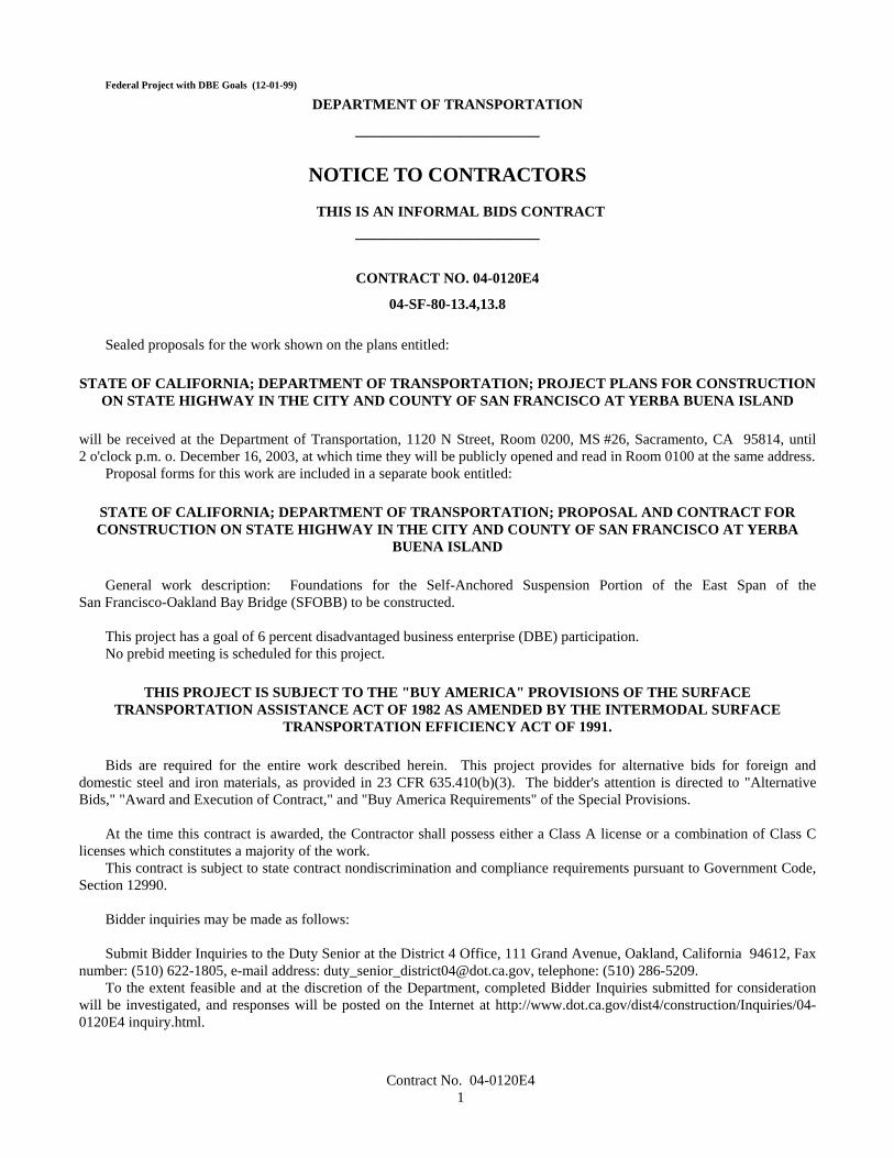
Federal Project with DBE Goals (12-01-99)
DEPARTMENT OF TRANSPORTATION
_________________________
NOTICE TO CONTRACTORS
THIS IS AN INFORMAL BIDS CONTRACT_________________________
CONTRACT NO. 04-0120E4
04-SF-80-13.4,13.8
Sealed proposals for the work shown on the plans entitled:
STATE OF CALIFORNIA; DEPARTMENT OF TRANSPORTATION; PROJECT PLANS FOR CONSTRUCTIONON STATE HIGHWAY IN THE CITY AND COUNTY OF SAN FRANCISCO AT YERBA BUENA ISLAND
will be received at the Department of Transportation, 1120 N Street, Room 0200, MS #26, Sacramento, CA 95814, until2 o'clock p.m. o. December 16, 2003, at which time they will be publicly opened and read in Room 0100 at the same address.
Proposal forms for this work are included in a separate book entitled:
STATE OF CALIFORNIA; DEPARTMENT OF TRANSPORTATION; PROPOSAL AND CONTRACT FORCONSTRUCTION ON STATE HIGHWAY IN THE CITY AND COUNTY OF SAN FRANCISCO AT YERBA
BUENA ISLAND
General work description: Foundations for the Self-Anchored Suspension Portion of the East Span of theSan Francisco-Oakland Bay Bridge (SFOBB) to be constructed.
This project has a goal of 6 percent disadvantaged business enterprise (DBE) participation.No prebid meeting is scheduled for this project.
THIS PROJECT IS SUBJECT TO THE "BUY AMERICA" PROVISIONS OF THE SURFACETRANSPORTATION ASSISTANCE ACT OF 1982 AS AMENDED BY THE INTERMODAL SURFACE
TRANSPORTATION EFFICIENCY ACT OF 1991.
Bids are required for the entire work described herein. This project provides for alternative bids for foreign anddomestic steel and iron materials, as provided in 23 CFR 635.410(b)(3). The bidder's attention is directed to "AlternativeBids," "Award and Execution of Contract," and "Buy America Requirements" of the Special Provisions.
At the time this contract is awarded, the Contractor shall possess either a Class A license or a combination of Class Clicenses which constitutes a majority of the work.
This contract is subject to state contract nondiscrimination and compliance requirements pursuant to Government Code,Section 12990.
Bidder inquiries may be made as follows:
Submit Bidder Inquiries to the Duty Senior at the District 4 Office, 111 Grand Avenue, Oakland, California 94612, Faxnumber: (510) 622-1805, e-mail address: [email protected], telephone: (510) 286-5209.
To the extent feasible and at the discretion of the Department, completed Bidder Inquiries submitted for considerationwill be investigated, and responses will be posted on the Internet at http://www.dot.ca.gov/dist4/construction/Inquiries/04-0120E4 inquiry.html.
Contract No. 04-0120E42
Responses to Bidder inquiries are provided to designate the contract requirements that address the inquiries. Revisionsand additions to the contract requirements will only be issued as contract addenda. Attention is directed to the provisions ofSection 2-1.03, "Examination of Plans, Specifications, Contract, and Site of Work," of the Standard Specifications. Theresponses may be considered along with other information furnished to prospective bidders. The questions and answersposted may represent summaries of questions submitted and responses to them. Bidders are cautioned that subsequentresponses and contract addenda may be issued and should be taken into consideration when submitting a bid.
Information handouts, as listed in various special provisions and summarized in, "Project Information," of these specialprovisons, are available on CD ROMs for inspection.
Project plans, special provisions, and proposal forms for bidding this project can only be obtained at the Department ofTransportation, Plans and Bid Documents, Room 0200, MS #26, Transportation Building, 1120 N Street, Sacramento,California 95814, FAX No. (916) 654-7028, Telephone No. (916) 654-4490. Use FAX orders to expedite orders for projectplans, special provisions and proposal forms. FAX orders must include credit card charge number, card expiration date andauthorizing signature. Project plans, special provisions, and proposal forms may be seen at the above Department ofTransportation office and at the offices of the District Directors of Transportation at Irvine, Oakland, and the district inwhich the work is situated. Standard Specifications and Standard Plans are available through the State of California,Department of Transportation, Publications Unit, 1900 Royal Oaks Drive, Sacramento, CA 95815, Telephone No.(916) 445-3520.
Cross sections for this project are not available.The successful bidder shall furnish a payment bond and a performance bond.The Department of Transportation hereby notifies all bidders that it will affirmatively ensure that in any contract entered
into pursuant to this advertisement, disadvantaged business enterprises will be afforded full opportunity to submit bids inresponse to this invitation.
The U.S. Department of Transportation (DOT) provides a toll-free "hotline" service to report bid rigging activities. Bidrigging activities can be reported Mondays through Fridays, between 8:00 a.m. and 5:00 p.m., eastern time, Telephone No.1-800-424-9071. Anyone with knowledge of possible bid rigging, bidder collusion, or other fraudulent activities should usethe "hotline" to report these activities. The "hotline" is part of the DOT's continuing effort to identify and investigatehighway construction contract fraud and abuse and is operated under the direction of the DOT Inspector General. Allinformation will be treated confidentially and caller anonymity will be respected.
Pursuant to Section 1773 of the Labor Code, the general prevailing wage rates in the county, or counties, in which thework is to be done have been determined by the Director of the California Department of Industrial Relations. These wagesare set forth in the General Prevailing Wage Rates for this project, available at the Labor Compliance Office at the offices ofthe District Director of Transportation for the district in which the work is situated, and available from the CaliforniaDepartment of Industrial Relations’ internet web site at: http://www.dir.ca.gov. The Federal minimum wage rates for thisproject as predetermined by the United States Secretary of Labor are available through the California Department ofTransportation's Electronic Project Document Distribution Site on the internet at http://hqidoc1.dot.ca.gov/. Addenda tomodify the Federal minimum wage rates, if necessary, will be issued to holders of "Proposal and Contract" books. Futureeffective general prevailing wage rates which have been predetermined and are on file with the California Department ofIndustrial Relations are referenced but not printed in the general prevailing wage rates.
If there is a difference between the minimum wage rates predetermined by the United States Secretary of Labor and thegeneral prevailing wage rates determined by the Director of the California Department of Industrial Relations for similarclassifications of labor, the Contractor and subcontractors shall pay not less than the higher wage rate. The Department willnot accept lower State wage rates not specifically included in the Federal minimum wage determinations. This includes"helper" (or other classifications based on hours of experience) or any other classification not appearing in the Federal wagedeterminations. Where Federal wage determinations do not contain the State wage rate determination otherwise available foruse by the Contractor and subcontractors, the Contractor and subcontractors shall pay not less than the Federal minimumwage rate which most closely approximates the duties of the employees in question.
DEPARTMENT OF TRANSPORTATION
Deputy Director Transportation Engineering
Dated October 17, 2003,
Contract No. 04-0120E43
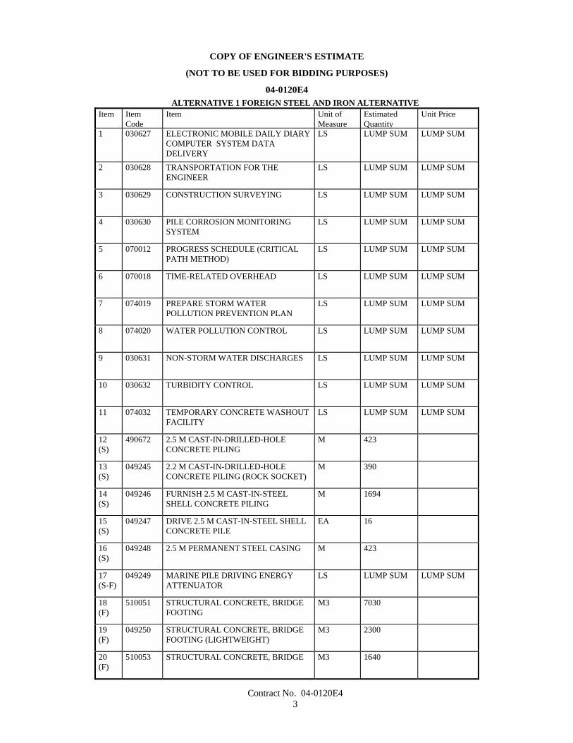
COPY OF ENGINEER'S ESTIMATE
(NOT TO BE USED FOR BIDDING PURPOSES)
04-0120E4ALTERNATIVE 1 FOREIGN STEEL AND IRON ALTERNATIVE
Item ItemCode
Item Unit ofMeasure
EstimatedQuantity
Unit Price
1 030627 ELECTRONIC MOBILE DAILY DIARYCOMPUTER SYSTEM DATADELIVERY
LS LUMP SUM LUMP SUM
2 030628 TRANSPORTATION FOR THEENGINEER
LS LUMP SUM LUMP SUM
3 030629 CONSTRUCTION SURVEYING LS LUMP SUM LUMP SUM
4 030630 PILE CORROSION MONITORINGSYSTEM
LS LUMP SUM LUMP SUM
5 070012 PROGRESS SCHEDULE (CRITICALPATH METHOD)
LS LUMP SUM LUMP SUM
6 070018 TIME-RELATED OVERHEAD LS LUMP SUM LUMP SUM
7 074019 PREPARE STORM WATERPOLLUTION PREVENTION PLAN
LS LUMP SUM LUMP SUM
8 074020 WATER POLLUTION CONTROL LS LUMP SUM LUMP SUM
9 030631 NON-STORM WATER DISCHARGES LS LUMP SUM LUMP SUM
10 030632 TURBIDITY CONTROL LS LUMP SUM LUMP SUM
11 074032 TEMPORARY CONCRETE WASHOUTFACILITY
LS LUMP SUM LUMP SUM
12(S)
490672 2.5 M CAST-IN-DRILLED-HOLECONCRETE PILING
M 423
13(S)
049245 2.2 M CAST-IN-DRILLED-HOLECONCRETE PILING (ROCK SOCKET)
M 390
14(S)
049246 FURNISH 2.5 M CAST-IN-STEELSHELL CONCRETE PILING
M 1694
15(S)
049247 DRIVE 2.5 M CAST-IN-STEEL SHELLCONCRETE PILE
EA 16
16(S)
049248 2.5 M PERMANENT STEEL CASING M 423
17(S-F)
049249 MARINE PILE DRIVING ENERGYATTENUATOR
LS LUMP SUM LUMP SUM
18(F)
510051 STRUCTURAL CONCRETE, BRIDGEFOOTING
M3 7030
19(F)
049250 STRUCTURAL CONCRETE, BRIDGEFOOTING (LIGHTWEIGHT)
M3 2300
20(F)
510053 STRUCTURAL CONCRETE, BRIDGE M3 1640
Contract No. 04-0120E44
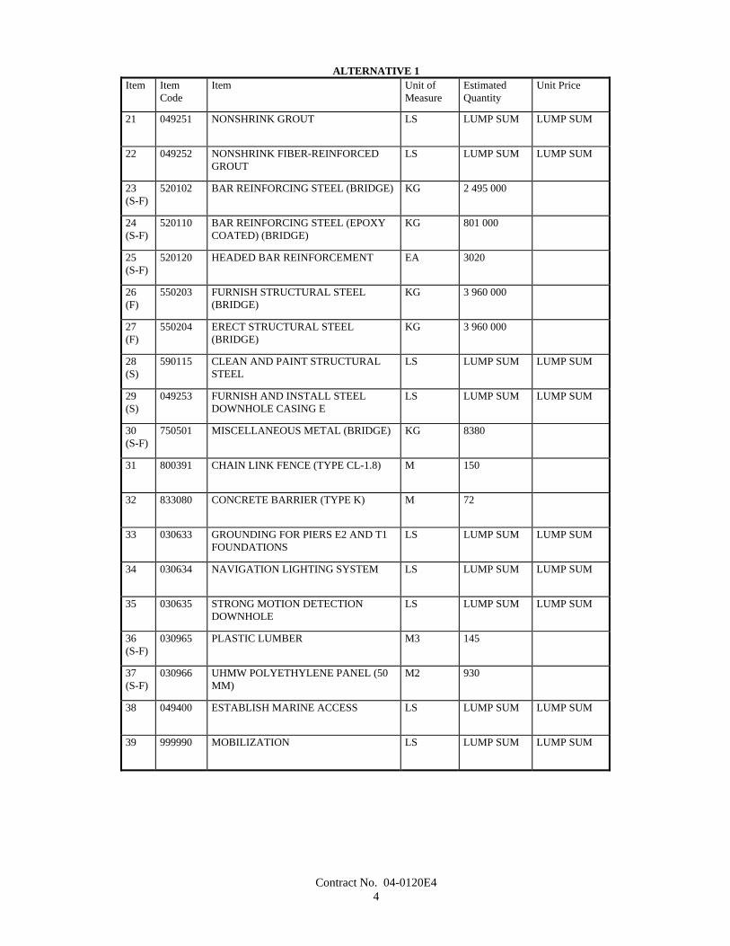
ALTERNATIVE 1Item Item
CodeItem Unit of
MeasureEstimatedQuantity
Unit Price
21 049251 NONSHRINK GROUT LS LUMP SUM LUMP SUM
22 049252 NONSHRINK FIBER-REINFORCEDGROUT
LS LUMP SUM LUMP SUM
23(S-F)
520102 BAR REINFORCING STEEL (BRIDGE) KG 2 495 000
24(S-F)
520110 BAR REINFORCING STEEL (EPOXYCOATED) (BRIDGE)
KG 801 000
25(S-F)
520120 HEADED BAR REINFORCEMENT EA 3020
26(F)
550203 FURNISH STRUCTURAL STEEL(BRIDGE)
KG 3 960 000
27(F)
550204 ERECT STRUCTURAL STEEL(BRIDGE)
KG 3 960 000
28(S)
590115 CLEAN AND PAINT STRUCTURALSTEEL
LS LUMP SUM LUMP SUM
29(S)
049253 FURNISH AND INSTALL STEELDOWNHOLE CASING E
LS LUMP SUM LUMP SUM
30(S-F)
750501 MISCELLANEOUS METAL (BRIDGE) KG 8380
31 800391 CHAIN LINK FENCE (TYPE CL-1.8) M 150
32 833080 CONCRETE BARRIER (TYPE K) M 72
33 030633 GROUNDING FOR PIERS E2 AND T1FOUNDATIONS
LS LUMP SUM LUMP SUM
34 030634 NAVIGATION LIGHTING SYSTEM LS LUMP SUM LUMP SUM
35 030635 STRONG MOTION DETECTIONDOWNHOLE
LS LUMP SUM LUMP SUM
36(S-F)
030965 PLASTIC LUMBER M3 145
37(S-F)
030966 UHMW POLYETHYLENE PANEL (50MM)
M2 930
38 049400 ESTABLISH MARINE ACCESS LS LUMP SUM LUMP SUM
39 999990 MOBILIZATION LS LUMP SUM LUMP SUM
Contract No. 04-0120E45
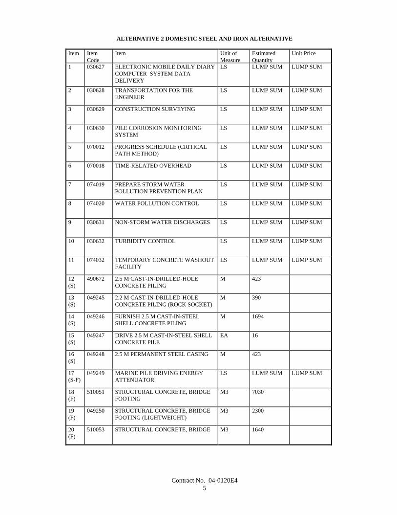
ALTERNATIVE 2 DOMESTIC STEEL AND IRON ALTERNATIVE
Item ItemCode
Item Unit ofMeasure
EstimatedQuantity
Unit Price
1 030627 ELECTRONIC MOBILE DAILY DIARYCOMPUTER SYSTEM DATADELIVERY
LS LUMP SUM LUMP SUM
2 030628 TRANSPORTATION FOR THEENGINEER
LS LUMP SUM LUMP SUM
3 030629 CONSTRUCTION SURVEYING LS LUMP SUM LUMP SUM
4 030630 PILE CORROSION MONITORINGSYSTEM
LS LUMP SUM LUMP SUM
5 070012 PROGRESS SCHEDULE (CRITICALPATH METHOD)
LS LUMP SUM LUMP SUM
6 070018 TIME-RELATED OVERHEAD LS LUMP SUM LUMP SUM
7 074019 PREPARE STORM WATERPOLLUTION PREVENTION PLAN
LS LUMP SUM LUMP SUM
8 074020 WATER POLLUTION CONTROL LS LUMP SUM LUMP SUM
9 030631 NON-STORM WATER DISCHARGES LS LUMP SUM LUMP SUM
10 030632 TURBIDITY CONTROL LS LUMP SUM LUMP SUM
11 074032 TEMPORARY CONCRETE WASHOUTFACILITY
LS LUMP SUM LUMP SUM
12(S)
490672 2.5 M CAST-IN-DRILLED-HOLECONCRETE PILING
M 423
13(S)
049245 2.2 M CAST-IN-DRILLED-HOLECONCRETE PILING (ROCK SOCKET)
M 390
14(S)
049246 FURNISH 2.5 M CAST-IN-STEELSHELL CONCRETE PILING
M 1694
15(S)
049247 DRIVE 2.5 M CAST-IN-STEEL SHELLCONCRETE PILE
EA 16
16(S)
049248 2.5 M PERMANENT STEEL CASING M 423
17(S-F)
049249 MARINE PILE DRIVING ENERGYATTENUATOR
LS LUMP SUM LUMP SUM
18(F)
510051 STRUCTURAL CONCRETE, BRIDGEFOOTING
M3 7030
19(F)
049250 STRUCTURAL CONCRETE, BRIDGEFOOTING (LIGHTWEIGHT)
M3 2300
20(F)
510053 STRUCTURAL CONCRETE, BRIDGE M3 1640

Contract No. 04-0120E46
ALTERNATIVE 2Item Item
CodeItem Unit of
MeasureEstimatedQuantity
Unit Price
21 049251 NONSHRINK GROUT LS LUMP SUM LUMP SUM
22 049252 NONSHRINK FIBER-REINFORCEDGROUT
LS LUMP SUM LUMP SUM
23(S-F)
520102 BAR REINFORCING STEEL (BRIDGE) KG 2 495 000
24(S-F)
520110 BAR REINFORCING STEEL (EPOXYCOATED) (BRIDGE)
KG 801 000
25(S-F)
520120 HEADED BAR REINFORCEMENT EA 3020
26(F)
550203 FURNISH STRUCTURAL STEEL(BRIDGE)
KG 3 960 000
27(F)
550204 ERECT STRUCTURAL STEEL(BRIDGE)
KG 3 960 000
28(S)
590115 CLEAN AND PAINT STRUCTURALSTEEL
LS LUMP SUM LUMP SUM
29(S)
049253 FURNISH AND INSTALL STEELDOWNHOLE CASING E
LS LUMP SUM LUMP SUM
30(S-F)
750501 MISCELLANEOUS METAL (BRIDGE) KG 8380
31 800391 CHAIN LINK FENCE (TYPE CL-1.8) M 150
32 833080 CONCRETE BARRIER (TYPE K) M 72
33 030633 GROUNDING FOR PIERS E2 AND T1FOUNDATIONS
LS LUMP SUM LUMP SUM
34 030634 NAVIGATION LIGHTING SYSTEM LS LUMP SUM LUMP SUM
35 030635 STRONG MOTION DETECTIONDOWNHOLE
LS LUMP SUM LUMP SUM
36(S-F)
030965 PLASTIC LUMBER M3 145
37(S-F)
030966 UHMW POLYETHYLENE PANEL (50MM)
M2 930
38 049400 ESTABLISH MARINE ACCESS LS LUMP SUM LUMP SUM
39 999990 MOBILIZATION LS LUMP SUM LUMP SUM
Contract No. 04-0120E47
STATE OF CALIFORNIA
DEPARTMENT OF TRANSPORTATION
_____________________________
SPECIAL PROVISIONS
Annexed to Contract No. 04-0120E4
SECTION 1. SPECIFICATIONS AND PLANS
The work embraced herein shall conform to the provisions in the Standard Specifications dated July 1999, and theStandard Plans dated July 1999, of the Department of Transportation insofar as the same may apply, and these specialprovisions.
In case of conflict between the Standard Specifications and these special provisions, the special provisions shall takeprecedence over and shall be used in lieu of the conflicting portions.
AMENDMENTS TO JULY 1999 STANDARDSPECIFICATIONS
UPDATED JUNE 19, 2003
Amendments to the Standard Specifications set forth in these special provisions shall be considered as part of theStandard Specifications for the purposes set forth in Section 5-1.04, "Coordination and Interpretation of Plans, StandardSpecifications and Special Provisions," of the Standard Specifications. Whenever either the term "Standard Specifications isamended" or the term "Standard Specifications are amended" is used in the special provisions, the text or table following theterm shall be considered an amendment to the Standard Specifications. In case of conflict between such amendments and theStandard Specifications, the amendments shall take precedence over and be used in lieu of the conflicting portions.
SECTION 2: PROPOSAL REQUIREMENTS AND CONDITIONS
Issue Date: June 19, 2003
Section 2-1.03, "Examination of Plans, Specifications, Contract, and Site of Work," of the Standard Specifications isamended to read:
2-1.03 Examination of Plans, Specifications, Contract, and Site of Work• The bidder shall examine carefully the site of the work contemplated, the plans and specifications, and the proposal
and contract forms therefor. The submission of a bid shall be conclusive evidence that the bidder has investigated and issatisfied as to the general and local conditions to be encountered, as to the character, quality and scope of work to beperformed, the quantities of materials to be furnished and as to the requirements of the proposal, plans, specifications and thecontract.
• The submission of a bid shall also be conclusive evidence that the bidder is satisfied as to the character, quality andquantity of surface and subsurface materials or obstacles to be encountered insofar as this information was reasonablyascertainable from an inspection of the site and the records of exploratory work done by the Department as shown in the biddocuments, as well as from the plans and specifications made a part of the contract.
• Where the Department has made investigations of site conditions including subsurface conditions in areas wherework is to be performed under the contract, or in other areas, some of which may constitute possible local material sources,

Contract No. 04-0120E48
bidders or contractors may, upon written request, inspect the records of the Department as to those investigations subject toand upon the conditions hereinafter set forth.
• Where there has been prior construction by the Department or other public agencies within the project limits,records of the prior construction that are currently in the possession of the Department and which have been used by, or areknown to, the designers and administrators of the project will be made available for inspection by bidders or contractors,upon written request, subject to the conditions hereinafter set forth. The records may include, but are not limited to, as-builtdrawings, design calculations, foundation and site studies, project reports and other data assembled in connection with theinvestigation, design, construction and maintenance of the prior projects.
• Inspection of the records of investigations and project records may be made at the office of the district in which thework is situated, or in the case of records of investigations related to structure work, at the Transportation Laboratory inSacramento, California.
• When a log of test borings or other record of geotechnical data obtained by the Department's investigation ofsurface and subsurface conditions is included with the contract plans, it is furnished for the bidders' or Contractor'sinformation and its use shall be subject to the conditions and limitations set forth in this Section 2-1.03.
• In some instances, information considered by the Department to be of possible interest to bidders or contractors hasbeen compiled as "Materials Information." The use of the "Materials Information" shall be subject to the conditions andlimitations set forth in this Section 2-1.03 and Section 6-2, "Local Materials."
• When cross sections are not included with the plans, but are available, bidders or contractors may inspect the crosssections and obtain copies for their use, at their expense.
• When cross sections are included with the contract plans, it is expressly understood and agreed that the crosssections do not constitute part of the contract, do not necessarily represent actual site conditions or show location, character,dimensions and details of work to be performed, and are included in the plans only for the convenience of bidders and theiruse is subject to the conditions and limitations set forth in this Section 2-1.03.
• When contour maps were used in the design of the project, the bidders may inspect those maps, and if available,they may obtain copies for their use.
• The availability or use of information described in this Section 2-1.03 is not to be construed in any way as a waiverof the provisions of the first paragraph in this Section 2-1.03 and bidders and contractors are cautioned to make independentinvestigations and examinations as they deem necessary to be satisfied as to conditions to be encountered in the performanceof the work and, with respect to possible local material sources, the quality and quantity of material available from theproperty and the type and extent of processing that may be required in order to produce material conforming to therequirements of the specifications.
• The Department assumes no responsibility for conclusions or interpretations made by a bidder or contractor basedon the information or data made available by the Department. The Department does not assume responsibility forrepresentation made by its officers or agents before the execution of the contract concerning surface or subsurfaceconditions, unless that representation is expressly stated in the contract.
• No conclusions or interpretations made by a bidder or contractor from the information and data made available bythe Department will relieve a bidder or contractor from properly fulfilling the terms of the contract.
SECTION 5: CONTROL OF WORK
Issue Date: December 31, 2001
Section 5-1.02A, "Trench Excavation Safety Plans," of the Standard Specifications is amended to read:
5-1.02A Excavation Safety Plans• The Construction Safety Orders of the Division of Occupational Safety and Health shall apply to all excavations.
For all excavations 1.5 m or more in depth, the Contractor shall submit to the Engineer a detailed plan showing the designand details of the protective systems to be provided for worker protection from the hazard of caving ground duringexcavation. The detailed plan shall include any tabulated data and any design calculations used in the preparation of theplan. Excavation shall not begin until the detailed plan has been reviewed and approved by the Engineer.
• Detailed plans of protective systems for which the Construction Safety Orders require design by a registeredprofessional engineer shall be prepared and signed by an engineer who is registered as a Civil Engineer in the State ofCalifornia, and shall include the soil classification, soil properties, soil design calculations that demonstrate adequate stabilityof the protective system, and any other design calculations used in the preparation of the plan.
• No plan shall allow the use of a protective system less effective than that required by the Construction SafetyOrders.
Contract No. 04-0120E49
• If the detailed plan includes designs of protective systems developed only from the allowable configurations andslopes, or Appendices, contained in the Construction Safety Orders, the plan shall be submitted at least 5 days before theContractor intends to begin excavation. If the detailed plan includes designs of protective systems developed from tabulateddata, or designs for which design by a registered professional engineer is required, the plan shall be submitted at least 3weeks before the Contractor intends to begin excavation.
• Attention is directed to Section 7-1.01E, "Trench Safety."
SECTION 9: MEASUREMENT AND PAYMENT
Issue Date: November 18, 2002
Section 9-1.04, "Notice of Potential Claim," of the Standard Specifications is amended to read:
9-1.04 NOTICE OF POTENTIAL CLAIM• It is the intention of this section that disputes between the parties arising under and by virtue of the contract be
brought to the attention of the Engineer at the earliest possible time in order that the matters may be resolved, if possible, orother appropriate action promptly taken.
• Disputes will not be considered unless the Contractor has first complied with specified notice or protestrequirements, including Section 4-1.03, "Changes," Section 5-1.116, "Differing Site Conditions," Section 8-1.06, "Time ofCompletion," Section 8-1.07, "Liquidated Damages," and Section 8-1.10, "Utility and Non-Highway Facilities."
• For disputes arising under and by virtue of the contract, including an act or failure to act by the Engineer, theContractor shall provide a signed written initial notice of potential claim to the Engineer within 5 days from the date thedispute first arose. The initial notice of potential claim shall provide the nature and circumstances involved in the disputewhich shall remain consistent through the dispute. The initial notice of potential claim shall be submitted on FormCEM-6201A furnished by the Department and shall be certified with reference to the California False Claims Act,Government Code Sections 12650-12655. The Contractor shall assign an exclusive identification number for each dispute,determined by chronological sequencing, based on the date of the dispute.
• The exclusive identification number for each dispute shall be used on the following corresponding documents:
A. Initial notice of potential claim.B. Supplemental notice of potential claim.C. Full and final documentation of potential claim.D. Corresponding claim included in the Contractor's written statement of claims.
• The Contractor shall provide the Engineer the opportunity to examine the site of work within 5 days from the dateof the initial notice of potential claim. The Contractor shall proceed with the performance of contract work unless otherwisespecified or directed by the Engineer.
• Throughout the disputed work, the Contractor shall maintain records that provide a clear distinction between theincurred direct costs of disputed work and that of undisputed work. The Contractor shall allow the Engineer access to theContractor's project records deemed necessary by the Engineer to evaluate the potential claim within 20 days of the date ofthe Engineer's written request.
• Within 15 days of submitting the initial notice of potential claim, the Contractor shall provide a signed supplementalnotice of potential claim to the Engineer that provides the following information:
A. The complete nature and circumstances of the dispute which caused the potential claim.B. The contract provisions that provide the basis of claim.C. The estimated cost of the potential claim, including an itemized breakdown of individual costs and how the estimate
was determined.D. A time impact analysis of the project schedule that illustrates the effect on the scheduled completion date due to
schedule changes or disruptions where a request for adjustment of contract time is made.
• The information provided in items A and B above shall provide the Contractor's complete reasoning for additionalcompensation or adjustments.
• The supplemental notice of potential claim shall be submitted on Form CEM-6201B furnished by the Departmentand shall be certified with reference to the California False Claims Act, Government Code Sections 12650-12655. TheEngineer will evaluate the information presented in the supplemental notice of potential claim and provide a written responseto the Contractor within 20 days of its receipt. If the estimated cost or effect on the scheduled completion date changes, the
Contract No. 04-0120E410
Contractor shall update information in items C and D above as soon as the change is recognized and submit this informationto the Engineer.
• Within 30 days of the completion of work related to the potential claim, the Contractor shall provide the full andfinal documentation of potential claim to the Engineer that provides the following information:
A. A detailed factual narration of events fully describing the nature and circumstances that caused the dispute,including, but not limited to, necessary dates, locations, and items of work affected by the dispute.
B. The specific provisions of the contract that support the potential claim and a statement of the reasons theseprovisions support and provide a basis for entitlement of the potential claim.
C. When additional monetary compensation is requested, the exact amount requested calculated in conformance withSection 9-1.03, "Force Account Payment," or Section 8-1.09, "Right of Way Delays," including an itemizedbreakdown of individual costs. These costs shall be segregated into the following cost categories:
1. Labor – A listing of individuals, classifications, regular hours and overtime hours worked, dates worked, andother pertinent information related to the requested reimbursement of labor costs.
2. Materials – Invoices, purchase orders, location of materials either stored or incorporated into the work, datesmaterials were transported to the project or incorporated into the work, and other pertinent information relatedto the requested reimbursement of material costs.
3. Equipment – Listing of detailed description (make, model, and serial number), hours of use, dates of use andequipment rates. Equipment rates shall be at the applicable State rental rate as listed in the Department ofTransportation publication entitled "Labor Surcharge and Equipment Rental Rates," in effect when the affectedwork related to the dispute was performed.
4. Other categories as specified by the Contractor or the Engineer.
A. When an adjustment of contract time is requested the following information shall be provided:
1. The specific dates for which contract time is being requested.2. The specific reasons for entitlement to a contract time adjustment.3. The specific provisions of the contract that provide the basis for the requested contract time adjustment.4. A detailed time impact analysis of the project schedule. The time impact analysis shall show the effect of
changes or disruptions on the scheduled completion date to demonstrate entitlement to a contract timeadjustment.
B. The identification and copies of the Contractor's documents and the substance of oral communications that supportthe potential claim.
• The full and final documentation of the potential claim shall be submitted on Form CEM-6201C furnished by theDepartment and shall be certified with reference to the California False Claims Act, Government Code Sections12650-12655.
• Pertinent information, references, arguments, and data to support the potential claim shall be included in the full andfinal documentation of potential claim. Information submitted subsequent to the full and final documentation submittal willnot be considered. Information required in the full and final documentation of potential claim, as listed in items A to Eabove, that is not applicable to the dispute may be exempted as determined by the Engineer. No full and final documentationof potential claim will be considered that does not have the same nature and circumstances, and basis of claim as thosespecified on the initial and supplemental notices of potential claim.
• The Engineer will evaluate the information presented in the full and final documentation of potential claim andprovide a written response to the Contractor within 30 days of its receipt unless otherwise specified. The Engineer's receiptof the full and final documentation of potential claim shall be evidenced by postal receipt or the Engineer's written receipt ifdelivered by hand. If the full and final documentation of potential claim is submitted by the Contractor after acceptance ofthe work by the Director, the Engineer need not provide a written response.
• Provisions in this section shall not apply to those claims for overhead costs and administrative disputes that occurafter issuance of the proposed final estimate. Administrative disputes are disputes of administrative deductions or retentions,contract item quantities, contract item adjustments, interest payments, protests of contract change orders as provided inSection 4-1.03A, "Procedure and Protest," and protests of the weekly statement of working days as provided in Section8-1.06, "Time of Completion." Administrative disputes that occur prior to issuance of the proposed final estimate shallfollow applicable requirements of this section. Information listed in the supplemental notice and full and finaldocumentation of potential claim that is not applicable to the administrative dispute may be exempted as determined by theEngineer.
Contract No. 04-0120E411
• Unless otherwise specified in the special provisions, the Contractor may pursue the administrative claim processpursuant to Section 9-1.07B, "Final Payment and Claims," for any potential claim found by the Engineer to be without merit.
• Failure of the Contractor to conform to specified dispute procedures shall constitute a failure to pursue diligentlyand exhaust the administrative procedures in the contract, and is deemed as the Contractor's waiver of the potential claim anda waiver of the right to a corresponding claim for the disputed work in the administrative claim process in conformance withSection 9-1.07B, "Final Payment of Claims," and shall operate as a bar to arbitration pursuant to Section 10240.2 of theCalifornia Public Contract Code.
Section 9-1.07B, "Final Payment and Claims," of the Standard Specifications is amended to read:
9-1.07B Final Payment and Claims• After acceptance by the Director, the Engineer will make a proposed final estimate in writing of the total amount
payable to the Contractor, including an itemization of the total amount, segregated by contract item quantities, extra workand other bases for payment, and shall also show each deduction made or to be made for prior payments and amounts to bekept or retained under the provisions of the contract. Prior estimates and payments shall be subject to correction in theproposed final estimate. The Contractor shall submit written approval of the proposed final estimate or a written statement ofclaims arising under or by virtue of the contract so that the Engineer receives the written approval or statement of claims nolater than close of business of the thirtieth day after receiving the proposed final estimate. If the thirtieth day falls on aSaturday, Sunday or legal holiday, then receipt of the written approval or statement of claims by the Engineer shall not belater than close of business of the next business day. The Contractor's receipt of the proposed final estimate shall beevidenced by postal receipt. The Engineer's receipt of the Contractor's written approval or statement of claims shall beevidenced by postal receipt or the Engineer's written receipt if delivered by hand.
• On the Contractor's approval, or if the Contractor files no claim within the specified period of 30 days, the Engineerwill issue a final estimate in writing in conformance with the proposed final estimate submitted to the Contractor, and within30 days thereafter the State will pay the entire sum so found to be due. That final estimate and payment thereon shall beconclusive and binding against both parties to the contract on all questions relating to the amount of work done and thecompensation payable therefor, except as otherwise provided in Sections 9-1.03C, "Records," and 9-1.09, "Clerical Errors."
• If the Contractor within the specified period of 30 days files claims, the Engineer will issue a semifinal estimate inconformance with the proposed final estimate submitted to the Contractor and within 30 days thereafter the State will pay thesum found to be due. The semifinal estimate and corresponding payment shall be conclusive and binding against bothparties to the contract on each question relating to the amount of work done and the compensation payable therefor, exceptinsofar as affected by the claims filed within the time and in the manner required hereunder and except as otherwise providedin Sections 9-1.03C, "Records," and 9-1.09, "Clerical Errors."
• Except for claims for overhead costs and administrative disputes that occur after issuance of the proposed finalestimate, the Contractor shall only provide the following two items of information for each claim:
A. The exclusive identification number that corresponds to the supporting full and final documentation of potentialclaim.
B. The final amount of requested additional compensation.
• If the final amount of requested additional compensation is different than the amount of requested compensationincluded in the full and final documentation of potential claim, the Contractor shall provide in the written statement of claimsthe reasons for the changed amount, the specific provisions of the contract which support the changed amount, and astatement of the reasons the provisions support and provide a basis for the changed amount. If the Contractor's claim fails toprovide an exclusive identification number or if there is a disparity in the provided exclusive identification number, theEngineer will notify the Contractor of the omission or disparity. The Contractor shall have 15 days after receivingnotification from the Engineer to correct the omission or disparity. If after the 15 days has elapsed, there is still an omissionor disparity of the exclusive identification number assigned to the claim, the Engineer will assign the number. No claim willbe considered that has any of the following deficiencies:
A. The claim does not have the same nature, circumstances, and basis as the corresponding full and finaldocumentation of potential claim.
B. The claim does not have a corresponding full and final documentation of potential claim.C. The claim was not included in the written statement of claims.D. The Contractor did not comply with applicable notice or protest requirements of Sections 4-1.03, "Changes,"
5-1.116, "Differing Site Condition," 8-1.06, "Time of Completion," 8-1.07, "Liquidated Damages," 8-1.10, "Utilityand Non-Highway Facilities," and 9-1.04, "Notice of Potential Claim."

Contract No. 04-0120E412
• Administrative disputes that occur after issuance of the proposed final estimate shall be included in the Contractor'swritten statement of claims in sufficient detail to enable the Engineer to ascertain the basis and amounts of those claims.
• The Contractor shall keep full and complete records of the costs and additional time incurred for work for which aclaim for additional compensation is made. The Engineer or designated claim investigators or auditors shall have access tothose records and any other records as may be required by the Engineer to determine the facts or contentions involved in theclaims. Failure to permit access to those records shall be sufficient cause for denying the claims.
• The written statement of claims submitted by the Contractor shall be accompanied by a notarized certificatecontaining the following language:
Under the penalty of law for perjury or falsification and with specificreference to the California False Claims Act, Government Code Section12650 et. seq., the undersigned,
.(name)
of(title)
.(company)
hereby certifies that the claim for the additional compensation and time, ifany, made herein for the work on this contract is a true statement of theactual costs incurred and time sought, and is fully documented and supportedunder the contract between parties.
Dated
/s/
Subscribed and sworn before me this day
of .
(Notary Public)My CommissionExpires
• Failure to submit the notarized certificate will be sufficient cause for denying the claim.• Claims for overhead type expenses or costs, in addition to being certified as stated above, shall be supported and
accompanied by an audit report of an independent Certified Public Accountant. Omission of a supporting audit report of anindependent Certified Public Accountant shall result in denial of the claim and shall operate as a bar to arbitration, as to theclaim, in conformance with the requirements in Section 10240.2 of the California Public Contract Code. Claims foroverhead type expenses or costs shall be subject to audit by the State at its discretion. The costs of performing an auditexamination and submitting the report shall be borne by the Contractor. The Certified Public Accountant's audit examinationshall be performed in conformance with the requirements of the American Institute of Certified Public AccountantsAttestation Standards. The audit examination and report shall depict the Contractor's project and company-wide financialrecords and shall specify the actual overall average daily rates for both field and home office overhead for the entire durationof the project, and whether the costs have been properly allocated. The rates of field and home office overhead shall excludeunallowable costs as determined in Title 48 of the Federal Acquisition Regulations, Chapter 1, Part 31. The auditexamination and report shall determine if the rates of field and home office overhead are:
A. Allowable in conformance with the requirements in Title 48 of the Federal Acquisition Regulations, Chapter 1, Part31.
B. Adequately supported by reliable documentation.C. Related solely to the project under examination.
• Costs or expenses incurred by the State in reviewing or auditing claims that are not supported by the Contractor'scost accounting or other records shall be deemed to be damages incurred by the State within the meaning of the CaliforniaFalse Claims Act.
Contract No. 04-0120E413
• If the Contractor files a timely written statement of claims in response to the proposed final estimate, the Districtthat administers the contract will submit a claim position letter to the Contractor by hand delivery or deposit in the U.S. mailwithin 135 days of acceptance of the contract. The claim position letter will delineate the District's position on theContractor's claims. If the Contractor disagrees with the claim position letter, the Contractor shall submit a writtennotification of its disagreement and a written request to meet with the board of review, to be received by the District not laterthan 15 days after the Contractor's receipt of the claim position letter. The written notification of disagreement shall set forththe basis for the Contractor's disagreement and be submitted to the office designated in the claim position letter. TheContractor's failure to provide a timely written notification of disagreement or timely written request to meet with the boardof review shall constitute the Contractor's acceptance and agreement with the determinations provided in the claim positionletter and with final payment pursuant to the claim position letter.
• If the Contractor files a timely notification of disagreement with the District claim position letter and a timelyrequest to meet with the board of review, then the board of review, designated by the District Director to review claims thatremain in dispute, will meet with the Contractor within 45 days after receipt by the District of the notification ofdisagreement.
• If the District fails to submit a claim position letter to the Contractor within 135 days after the acceptance of thecontract and the Contractor has claims that remain in dispute, the Contractor may request a meeting with the board of reviewdesignated by the District Director to review claims that remain in dispute. The Contractor's request for a meeting shallidentify the claims that remain in dispute. If the Contractor files a request for a meeting, the board of review will meet withthe Contractor within 45 days after the District receives the request for the meeting.
• Attendance by the Contractor at the board of review meeting shall be mandatory. The board of review will reviewthose claims and make a written recommendation thereon to the District Director. The final determination of claims, madeby the District Director, will be sent to the Contractor by hand delivery or deposit in the U.S. mail. The Engineer will thenmake and issue the Engineer's final estimate in writing and within 30 days thereafter the State will pay the entire sum, if any,found due thereon. That final estimate shall be conclusive and binding against both parties to the contract on all questionsrelating to the amount of work done and the compensation payable therefor, except as otherwise provided in Sections9-1.03C, "Records," and 9-1.09, "Clerical Errors."
• Failure of the Contractor to conform to the specified dispute procedures shall constitute a failure to pursue diligentlyand exhaust the administrative procedures in the contract and shall operate as a bar to arbitration in conformance with therequirements in Section 10240.2 of the California Public Contract Code.
SECTION 19: EARTHWORK
Issue Date: December 31, 2001
The third paragraph of Section 19-1.02, "Preservation of Property," of the Standard Specifications is amended to read:
• In addition to the provisions in Sections 5-1.02, "Plans and Working Drawings," and 5-1.02A, "Excavation SafetyPlans," detailed plans of the protective systems for excavations on or affecting railroad property will be reviewed foradequacy of protection provided for railroad facilities, property, and traffic. These plans shall be submitted at least 9 weeksbefore the Contractor intends to begin excavation requiring the protective systems. Approval by the Engineer of the detailedplans for the protective systems will be contingent upon the plans being satisfactory to the railroad company involved.
SECTION 42: GROOVE AND GRIND PAVEMENT
Issue Date: December 31, 2001
The last sentence of the first subparagraph of the third paragraph in Section 42-2.02, "Construction," of the StandardSpecifications is amended to read:
• After grinding has been completed, the pavement shall conform to the straightedge and profile requirementsspecified in Section 40-1.10, "Final Finishing."
SECTION 49: PILING
Issue Date: April 30, 2003
The first paragraph in Section 49-1.03, "Determination of Length," of the Standard Specifications is amended to read:
Contract No. 04-0120E414
• Foundation piles of any material shall be of such length as is required to develop the nominal resistance, to obtainthe specified penetration, and to extend into the cap or footing block as shown on the plans, or specified in the specialprovisions.
The fourth paragraph in Section 49-1.03, "Determination of Length," of the Standard Specifications is amended to read:
• Modification to the specified installation methods and specified pile tip elevation will not be considered at locationswhere tension or lateral load demands control design pile tip elevations or when the plans state that specified pile tipelevation shall not be revised.
The sixth and seventh paragraphs in Section 49-1.03, "Determination of Length," of the Standard Specifications areamended to read:
• Indicator compression pile load testing shall conform to the requirements in ASTM Designation: D 1143. The pileshall sustain the first compression test load applied which is equal to the nominal resistance in compression, as shown on theplans, with no more than 13 mm total vertical movement at the top of the pile measured relative to the top of the pile prior tothe start of compression load testing.
• Indicator tension pile load testing shall conform to the requirements in ASTM Designation: D 3689. The loadingapparatus described as "Load Applied to Pile by Hydraulic Jack(s) Acting at One End of Test Beam(s) Anchored to the Pile"shall not be used. The pile shall sustain the first tension test load applied which is equal to the nominal resistance in tension,as shown on the plans, with no more than 13 mm total vertical movement at the top of the pile measured relative to the top ofthe pile prior to the start of tension load testing.
The ninth paragraph in Section 49-1.03, "Determination of Length," of the Standard Specifications is amended to read:
• For driven piling, the Contractor shall furnish piling of sufficient length to obtain both the specified tip elevationand nominal resistance shown on the plans or specified in the special provisions. For cast-in-drilled-hole concrete piling, theContractor shall construct piling of such length to develop the nominal resistance in compression and to obtain the specifiedtip elevation shown on the plans or specified in the special provisions.
The tenth paragraph in Section 49-1.03, "Determination of Length," of the Standard Specifications is deleted.
The fourth paragraph in Section 49-1.04, "Load Test Piles," of the Standard Specifications is amended to read:
• Load test piles and anchor piles which are not to be incorporated in the completed structure shall be removed inconformance with the provisions in Section 15-4.02, "Removal Methods," and the remaining holes shall be backfilled withearth or other suitable material approved by the Engineer.
The first paragraph in Section 49-1.05, "Driving Equipment," of the Standard Specifications is amended to read:
• Driven piles shall be installed with impact hammers that are approved in writing by the Engineer. Impact hammersshall be steam, hydraulic, air or diesel hammers. Impact hammers shall develop sufficient energy to drive the piles at apenetration rate of not less than 3 mm per blow at the specified nominal resistance.
The seventh paragraph in Section 49-1.05, "Driving Equipment," of the Standard Specifications is amended to read:
• When necessary to obtain the specified penetration and when authorized by the Engineer, the Contractor maysupply and operate one or more water jets and pumps, or furnish the necessary drilling apparatus and drill holes not greaterthan the least dimension of the pile to the proper depth and drive the piles therein. Jets shall not be used at locations wherethe stability of embankments or other improvements would be endangered. In addition, for steel piles, steel shells, or steelcasings, when necessary to obtain the specified penetration or to prevent damage to the pile during installation, theContractor shall provide special driving tips or heavier pile sections or take other measures as approved by the Engineer.
• The use of followers or underwater hammers for driving piles will be permitted if authorized in writing by theEngineer. When a follower or underwater hammer is used, its efficiency shall be verified by furnishing the first pile in eachbent or footing sufficiently long and driving the pile without the use of a follower or underwater hammer.
Contract No. 04-0120E415
The second paragraph in Section 49-1.07, "Driving," of the Standard Specifications is amended to read:
• Timber piles shall be fresh-headed and square and when permitted by the Engineer, the heads of the piles may beprotected by means of heavy steel or wrought iron rings. During driving operations timber piling shall be restrained fromlateral movement at intervals not to exceed 6 m over the length between the driving head and the ground surface. Duringdriving operations, the timber pile shall be kept moving by continuous operation of the hammer. When the blow countexceeds either 2 times the blow count required in 300 mm, or 3 times the blow count required in 75 mm for the nominalresistance as shown on the plans, computed in conformance with the provisions in Section 49-1.08, "Pile Driving AcceptanceCriteria," additional aids shall be used to obtain the specified penetration. These aids may include the use of water jets ordrilling, where permitted, or the use of a larger hammer employing a heavy ram striking with a low velocity.
Section 49-1.08, "Bearing Value and Penetration," of the Standard Specifications is amended to read:
49-1.08 PILE DRIVING ACCEPTANCE CRITERIA• Except for piles to be load tested, driven piles shall be driven to a value of not less than the nominal resistance
shown on the plans unless otherwise specified in the special provisions or permitted in writing by the Engineer. In addition,when a pile tip elevation is specified, driven piles shall penetrate at least to the specified tip elevation, unless otherwisepermitted in writing by the Engineer. Piles to be load tested shall be driven to the specified tip elevation.
• When the pile nominal resistance is omitted from the plans or the special provisions, timber piles shall be driven to anominal resistance of 800 kN, and steel and concrete piles shall be driven to a nominal resistance of 1250 kN.
• The nominal resistance for driven piles shall be determined from the following formula in which "Ru" is the nominalresistance in kilonewtons, "Er" is the manufacturer's rating for joules of energy developed by the hammer at the observedfield drop height, and "N" is the number of hammer blows in the last 300 millimeters. (maximum value to be used for N is100):
Ru = (7 * (Er)1/2*log10 (0.83 * N)) - 550
Section 49-3.01, "Description," of the Standard Specifications is amended by deleting the fifth paragraph.
The sixth paragraph in Section 49-4.01, "Description," of the Standard Specifications is amended to read:
• Lifting anchors used in precast prestressed concrete piles without a class designation ending in "C" (corrosionresistant) shall be removed, and the holes filled in conformance with the provisions in Section 51-1.18A, "Ordinary SurfaceFinish."
The first and second paragraphs in Section 49-4.01, "Description," of the Standard Specifications are amended to read:
• Cast-in-place concrete piles shall consist of one of the following:
A. Steel shells driven permanently to the required nominal resistance and penetration and filled with concrete.B. Steel casings installed permanently to the required penetration and filled with concrete.C. Drilled holes filled with concrete.D. Rock sockets filled with concrete.
• The drilling of holes shall conform to the provisions in these specifications. Concrete filling for cast-in-placeconcrete piles is designated by compressive strength and shall have a minimum 28-day compressive strength of 25 MPa. Atthe option of the Contractor, the combined aggregate grading for the concrete shall be either the 25-mm maximum grading,the 12.5-mm maximum grading, or the 9.5-mm maximum grading. Concrete shall conform to the provisions in Section 90,"Portland Cement Concrete," and Section 51, "Concrete Structures." Reinforcement shall conform to the provisions inSection 52, "Reinforcement."
The fourth paragraph in Section 49-4.03, "Drilled Holes," of the Standard Specifications is amended to read:
Contract No. 04-0120E416
• After placing reinforcement and prior to placing concrete in the drilled hole, if caving occurs or deterioratedfoundation material accumulates on the bottom of the hole, the bottom of the drilled hole shall be cleaned. The Contractorshall verify that the bottom of the drilled hole is clean.
The first and second paragraphs in Section 49-4.04, "Steel Shells," of the Standard Specifications are amended to read:
• Steel shells shall be sufficiently watertight to exclude water during the placing of concrete. The shells may becylindrical or tapered, step-tapered, or a combination of either, with cylindrical sections.
The first paragraph in Section 49-4.05, "Inspection," of the Standard Specifications is amended to read:
• After being driven and prior to placing reinforcement and concrete therein, the steel shells shall be examined forcollapse or reduced diameter at any point. Any shell which is improperly driven or broken or shows partial collapse to suchan extent as to materially decrease its nominal resistance will be rejected. Rejected shells shall be removed and replaced, or anew shell shall be driven adjacent to the rejected shell. Rejected shells which cannot be removed shall be filled withconcrete by the Contractor at the Contractor's expense. When a new shell is driven to replace a rejected shell, the Contractor,at the Contractor's expense, shall enlarge the footing as determined necessary by the Engineer.
The third paragraph in Section 49-6.02, "Payment," of the Standard Specifications is amended to read:
• The contract price paid per meter for cast-in-drilled-hole concrete piling shall include full compensation forfurnishing all labor, materials, tools, equipment, and incidentals, and for doing all work involved in drilling holes, disposingof material resulting from drilling holes, temporarily casing holes and removing water when necessary, furnishing andplacing concrete and reinforcement, and constructing reinforced concrete extensions, complete in place, to the requiredpenetration, as shown on the plans, as specified in these specifications and in the special provisions, and as directed by theEngineer.
The seventh paragraph in Section 49-6.02, "Payment," of the Standard Specifications is amended to read
• The contract unit price paid for drive pile shall include full compensation for furnishing all labor, materials, tools,equipment, and incidentals, and for doing all the work involved in driving timber, concrete and steel piles, driving steelshells for cast-in-place concrete piles, placing filling materials for cast-in-place concrete piles and cutting off piles, allcomplete in place to the required nominal resistance and penetration as shown on the plans and as specified in thesespecifications and the special provisions, and as directed by the Engineer.
The ninth paragraph in Section 49-6.02, "Payment," of the Standard Specifications is amended to read:
• Full compensation for all jetting, drilling, providing special driving tips or heavier sections for steel piles or shells,or other work necessary to obtain the specified penetration and nominal resistance of the piles, for predrilling holes throughembankment and filling the space remaining around the pile with sand or pea gravel, for disposing of material resulting fromjetting, drilling or predrilling holes, and for all excavation and backfill involved in constructing concrete extensions as shownon the plans, and as specified in these specifications and the special provisions, and as directed by the Engineer shall beconsidered as included in the contract unit price paid for drive pile or in the contract price paid per meter forcast-in-drilled-hole concrete piling, and no additional compensation will be allowed therefor.
Section 49-6.02, "Payment," of the Standard Specifications is amended by adding the following paragraphs:
Full compensation for furnishing and placing additional testing reinforcement, for load test anchorages, and for cuttingoff test piles, shall be considered as included in the contract price paid for piling of the type or class shown in the Engineer'sEstimate, and no additional compensation will be allowed.
No additional compensation or extension of time will be made for additional foundation investigation, installation andtesting of indicator piling, cutting off piling and restoring the foundation investigation and indicator pile sites, and review ofrequest by the Engineer
SECTION 50: PRESTRESSING CONCRETE
Contract No. 04-0120E417
Issue Date: November 18, 2002
Section 50-1.02, "Drawings," of the Standard Specifications is amended by adding the following paragraph after thesecond paragraph:
• Each working drawing submittal shall consist of plans for a single bridge or portion thereof. For multi-framebridges, each frame shall require a separate working drawing submittal.
Section 50-1.05, "Prestressing Steel," of the Standard Specifications is amended to read:
• Prestressing steel shall be high-tensile wire conforming to the requirements in ASTM Designation: A 421,including Supplement I; high-tensile seven-wire strand conforming to the requirements in ASTM Designation: A 416; oruncoated high-strength steel bars conforming to the requirements in ASTM Designation: A 722, including all supplementaryrequirements. The maximum mass requirement of ASTM Designation: A 722 will not apply.
• In addition to the requirements of ASTM Designation: A 722, for deformed bars, the reduction of area shall bedetermined from a bar from which the deformations have been removed. The bar shall be machined no more than necessaryto remove the deformations over a length of 300 mm, and reduction will be based on the area of the machined portion.
• In addition to the requirements specified herein, epoxy-coated seven-wire prestressing steel strand shall be gritimpregnated and filled in conformance with the requirements in ASTM Designation: A 882/A 882M, including SupplementI, and the following:
A. The coating material shall be on the Department's list of approved coating materials for epoxy-coated strand,available from the Transportation Laboratory.
B. The film thickness of the coating after curing shall be 381 µm to 1143 µm.C. Prior to coating the strand, the Contractor shall furnish to the Transportation Laboratory a representative 230-g
sample from each batch of epoxy coating material to be used. Each sample shall be packaged in an airtightcontainer identified with the manufacturer's name and batch number.
D. Prior to use of the epoxy-coated strand in the work, written certifications referenced in ASTM Designation:A 882/A 882M, including a representative load-elongation curve for each size and grade of strand to be used and acopy of the quality control tests performed by the manufacturer, shall be furnished to the Engineer.
E. In addition to the requirements in Section 50-1.10, "Samples for Testing," four 1.5-m long samples of coated strandand one 1.5-m long sample of uncoated strand of each size and reel shall be furnished to the Engineer for testing.These samples, as selected by the Engineer, shall be representative of the material to be used in the work.
F. Epoxy-coated strand shall be cut using an abrasive saw.G. All visible damage to coatings caused by shipping and handling, or during installation, including cut ends, shall be
repaired in conformance with the requirements in ASTM Designation: A 882/A 882M. The patching material shallbe furnished by the manufacturer of the epoxy powder and shall be applied in conformance with the manufacturer'swritten recommendations. The patching material shall be compatible with the original epoxy coating material andshall be inert in concrete.
• All bars in any individual member shall be of the same grade, unless otherwise permitted by the Engineer.• When bars are to be extended by the use of couplers, the assembled units shall have a tensile strength of not less
than the manufacturer's minimum guaranteed ultimate tensile strength of the bars. Failure of any one sample to meet thisrequirement will be cause for rejection of the heat of bars and lot of couplers. The location of couplers in the member shallbe subject to approval by the Engineer.
• Wires shall be straightened if necessary to produce equal stress in all wires or wire groups or parallel lay cables thatare to be stressed simultaneously or when necessary to ensure proper positioning in the ducts.
• Where wires are to be button-headed, the buttons shall be cold formed symmetrically about the axes of the wires.The buttons shall develop the minimum guaranteed ultimate tensile strength of the wire. No cold forming process shall beused that causes indentations in the wire. Buttonheads shall not contain wide open splits, more than 2 splits per head, orsplits not parallel with the axis of the wire.
• Prestressing steel shall be protected against physical damage and rust or other results of corrosion at all times frommanufacture to grouting or encasing in concrete. Prestressing steel that has sustained physical damage at any time shall berejected. The development of visible rust or other results of corrosion shall be cause for rejection, when ordered by theEngineer.
• Epoxy-coated prestressing steel strand shall be covered with an opaque polyethylene sheeting or other suitableprotective material to protect the strand from exposure to sunlight, salt spray, and weather. For stacked coils, the protectivecovering shall be draped around the perimeter of the stack. The covering shall be adequately secured; however, it should
Contract No. 04-0120E418
allow for air circulation around the strand to prevent condensation under the covering. Epoxy-coated strand shall not bestored within 300 m of ocean or tidal water for more than 2 months.
• Prestressing steel shall be packaged in containers or shipping forms for the protection of the steel against physicaldamage and corrosion during shipping and storage. Except for epoxy-coated strand, a corrosion inhibitor which preventsrust or other results of corrosion, shall be placed in the package or form, or shall be incorporated in a corrosion inhibitorcarrier type packaging material, or when permitted by the Engineer, may be applied directly to the steel. The corrosioninhibitor shall have no deleterious effect on the steel or concrete or bond strength of steel to concrete. Packaging or formsdamaged from any cause shall be immediately replaced or restored to original condition.
• The shipping package or form shall be clearly marked with a statement that the package contains high-strengthprestressing steel, and the type of corrosion inhibitor used, including the date packaged.
• Prestressing steel for post-tensioning which is installed in members prior to placing and curing of the concrete, andwhich is not epoxy-coated, shall be continuously protected against rust or other results of corrosion, until grouted, by meansof a corrosion inhibitor placed in the ducts or applied to the steel in the duct. The corrosion inhibitor shall conform to theprovisions specified herein.
• When steam curing is used, prestressing steel for post-tensioning shall not be installed until the steam curing iscompleted.
• Water used for flushing ducts shall contain either quick lime (calcium oxide) or slaked lime (calcium hydroxide) inthe amount of 0.01-kg/L. Compressed air used to blow out ducts shall be oil free.
• When prestressing steel for post-tensioning is installed in the ducts after completion of concrete curing, and ifstressing and grouting are completed within 10 days after the installation of the prestressing steel, rust which may formduring those 10 days will not be cause for rejection of the steel. Prestressing steel installed, tensioned, and grouted in thismanner, all within 10 days, will not require the use of a corrosion inhibitor in the duct following installation of theprestressing steel. Prestressing steel installed as above but not grouted within 10 days shall be subject to all the requirementsin this section pertaining to corrosion protection and rejection because of rust. The requirements in this section pertaining totensioning and grouting within 10 days shall not apply to epoxy-coated prestressing steel strand.
• Any time prestressing steel for pretensioning is placed in the stressing bed and is exposed to the elements for morethan 36 hours prior to encasement in concrete, adequate measures shall be taken by the Contractor, as approved by theEngineer, to protect the steel from contamination or corrosion.
• After final fabrication of the seven-wire prestressing steel strand, no electric welding of any form shall beperformed on the prestressing steel. Whenever electric welding is performed on or near members containing prestressingsteel, the welding ground shall be attached directly to the steel being welded.
• Pretensioned prestressing steel shall be cut off flush with the end of the member. For epoxy-coated prestressingsteel, only abrasive saws shall be used to cut the steel. The exposed ends of the prestressing steel and a 25-mm strip ofadjoining concrete shall be cleaned and painted. Cleaning shall be by wire brushing or abrasive blast cleaning to remove alldirt and residue on the metal or concrete surfaces. Immediately after cleaning, the surfaces shall be covered with oneapplication of unthinned zinc-rich primer (organic vehicle type) conforming to the provisions in Section 91, "Paint," exceptthat 2 applications shall be applied to surfaces which will not be covered by concrete or mortar. Aerosol cans shall not beused. The paint shall be thoroughly mixed at the time of application and shall be worked into any voids in the prestressingtendons.
The thirteenth paragraph in Section 50-1.08, "Prestressing," of the Standard Specifications is amended to read:
• Prestressing steel in pretensioned members shall not be cut or released until the concrete in the member has attaineda compressive strength of not less than the value shown on the plans or 28 MPa, whichever is greater. In addition to theseconcrete strength requirements, when epoxy-coated prestressing steel strand is used, the steel shall not be cut or releaseduntil the temperature of the concrete surrounding the strand is less than 65°C, and falling.
The fifth paragraph in Section 50-1.10, "Samples for Testing," of the Standard Specifications is amended to read:
• The following samples of materials and tendons, selected by the Engineer from the prestressing steel at the plant orjobsite, shall be furnished by the Contractor to the Engineer well in advance of anticipated use:
A. For wire or bars, one 2-m long sample and for strand, one 1.5-m long sample, of each size shall be furnished foreach heat or reel.
B. For epoxy-coated strand, one 1.5-m long sample of uncoated strand of each size shall be furnished for each reel.
Contract No. 04-0120E419
C. If the prestressing tendon is a bar, one 2-m long sample shall be furnished and in addition, if couplers are to be usedwith the bar, two 1.25-m long samples of bar, equipped with one coupler and fabricated to fit the coupler, shall befurnished.
The second paragraph in Section 50-1.11, "Payment," of the Standard Specifications is amended to read:
• The contract lump sum prices paid for prestressing cast-in-place concrete of the types listed in the Engineer'sEstimate shall include full compensation for furnishing all labor, materials, tools, equipment, and incidentals, and for doingall work involved in furnishing, placing, and tensioning the prestressing steel in cast-in-place concrete structures, complete inplace, as shown on the plans, as specified in these specifications and the special provisions, and as directed by the Engineer.
SECTION 51: CONCRETE STRUCTURES
Issue Date: April 16, 2003
The first and second paragraph in Section 51-1.06A, "Falsework Design and Drawings," of the Standard Specificationsare amended to read:
• The Contractor shall submit to the Engineer working drawings and design calculations for falsework proposed foruse at bridges. For bridges where the height of any portion of the falsework, as measured from the ground line to the soffitof the superstructure, exceeds 4.25 m; or where any individual falsework clear span length exceeds 4.85 m; or whereprovision for vehicular, pedestrian, or railroad traffic through the falsework is made; the drawings shall be signed by anengineer who is registered as a Civil Engineer in the State of California. Six sets of the working drawings and 2 copies ofthe design calculations shall be furnished. Additional working drawings and design calculations shall be submitted to theEngineer when specified in "Railroad Relations and Insurance" of the special provisions.
• The falsework drawings shall include details of the falsework erection and removal operations showing the methodsand sequences of erection and removal and the equipment to be used. The details of the falsework erection and removaloperations shall demonstrate the stability of all or any portions of the falsework during all stages of the erection and removaloperations.
The seventh paragraph in Section 51-1.06A, "Falsework Design and Drawings," of the Standard Specifications isamended to read:
• In the event that several falsework plans are submitted simultaneously, or an additional plan is submitted for reviewbefore the review of a previously submitted plan has been completed, the Contractor shall designate the sequence in whichthe plans are to be reviewed. In such event, the time to be provided for the review of any plan in the sequence shall be notless than the review time specified above for that plan, plus 2 weeks for each plan of higher priority which is still underreview. A falsework plan submittal shall consist of plans for a single bridge or portion thereof. For multi-frame bridges,each frame shall require a separate falsework plan submittal.
Section 51-1.06A, "Falsework Design and Drawings," of the Standard Specifications is amended by adding thefollowing paragraphs:
• If structural composite lumber is proposed for use, the falsework drawings shall clearly identify the structuralcomposite lumber members by grade (E value), species, and type. The Contractor shall provide technical data from themanufacturer showing the tabulated working stress values of the composite lumber. The Contractor shall furnish a certificateof compliance as specified in Section 6-1.07, "Certificates of Compliance," for each delivery of structural composite lumberto the project site.
• For falsework piles with a calculated loading capacity greater than 900 kN, the falsework piles shall be designed byan engineer who is registered as either a Civil Engineer or a Geotechnical Engineer in the State of California, and thecalculations shall be submitted to the Engineer.
The first paragraph in Section 51-1.06A(1), "Design Loads," of the Standard Specifications is amended to read:
• The design load for falsework shall consist of the sum of dead and live vertical loads, and an assumed horizontalload. The minimum total design load for any falsework, including members that support walkways, shall be not less than4800 N/m2 for the combined live and dead load regardless of slab thickness.
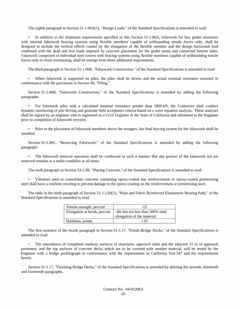
Contract No. 04-0120E420
The eighth paragraph in Section 51-1.06A(1), "Design Loads," of the Standard Specifications is amended to read:
• In addition to the minimum requirements specified in this Section 51-1.06A, falsework for box girder structureswith internal falsework bracing systems using flexible members capable of withstanding tensile forces only, shall bedesigned to include the vertical effects caused by the elongation of the flexible member and the design horizontal loadcombined with the dead and live loads imposed by concrete placement for the girder stems and connected bottom slabs.Falsework comprised of individual steel towers with bracing systems using flexible members capable of withstanding tensileforces only to resist overturning, shall be exempt from these additional requirements.
The third paragraph in Section 51-1.06B, "Falsework Construction," of the Standard Specifications is amended to read:
• When falsework is supported on piles, the piles shall be driven and the actual nominal resistance assessed inconformance with the provisions in Section 49, "Piling."
Section 51-1.06B, "Falsework Construction," of the Standard Specifications is amended by adding the followingparagraphs:
• For falsework piles with a calculated nominal resistance greater than 1800 kN, the Contractor shall conductdynamic monitoring of pile driving and generate field acceptance criteria based on a wave equation analysis. These analysesshall be signed by an engineer who is registered as a Civil Engineer in the State of California and submitted to the Engineerprior to completion of falsework erection.
• Prior to the placement of falsework members above the stringers, the final bracing system for the falsework shall beinstalled.
Section 51-1.06C, "Removing Falsework," of the Standard Specifications is amended by adding the followingparagraph:
• The falsework removal operation shall be conducted in such a manner that any portion of the falsework not yetremoved remains in a stable condition at all times.
The sixth paragraph in Section 51-1.09, "Placing Concrete," of the Standard Specifications is amended to read:
• Vibrators used to consolidate concrete containing epoxy-coated bar reinforcement or epoxy-coated prestressingsteel shall have a resilient covering to prevent damage to the epoxy-coating on the reinforcement or prestressing steel.
The table in the ninth paragraph of Section 51-1.12H(1), "Plain and Fabric Reinforced Elastomeric Bearing Pads," of theStandard Specifications is amended to read:
Tensile strength, percent -15Elongation at break, percent -40; but not less than 300% total
elongation of the materialHardness, points +10
The first sentence of the fourth paragraph in Section 51-1.17, "Finish Bridge Decks," of the Standard Specifications isamended to read:
• The smoothness of completed roadway surfaces of structures, approach slabs and the adjacent 15 m of approachpavement, and the top surfaces of concrete decks which are to be covered with another material, will be tested by theEngineer with a bridge profilograph in conformance with the requirements in California Test 547 and the requirementsherein.
Section 51-1.17, "Finishing Bridge Decks," of the Standard Specifications is amended by deleting the seventh, thirteenthand fourteenth paragraphs.
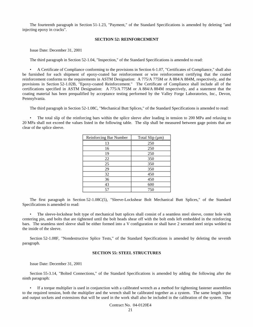
Contract No. 04-0120E421
The fourteenth paragraph in Section 51-1.23, "Payment," of the Standard Specifications is amended by deleting "andinjecting epoxy in cracks".
SECTION 52: REINFORCEMENT
Issue Date: December 31, 2001
The third paragraph in Section 52-1.04, "Inspection," of the Standard Specifications is amended to read:
• A Certificate of Compliance conforming to the provisions in Section 6-1.07, "Certificates of Compliance," shall alsobe furnished for each shipment of epoxy-coated bar reinforcement or wire reinforcement certifying that the coatedreinforcement conforms to the requirements in ASTM Designation: A 775/A 775M or A 884/A 884M, respectively, and theprovisions in Section 52-1.02B, "Epoxy-coated Reinforcement." The Certificate of Compliance shall include all of thecertifications specified in ASTM Designation: A 775/A 775M or A 884/A 884M respectively, and a statement that thecoating material has been prequalified by acceptance testing performed by the Valley Forge Laboratories, Inc., Devon,Pennsylvania.
The third paragraph in Section 52-1.08C, "Mechanical Butt Splices," of the Standard Specifications is amended to read:
• The total slip of the reinforcing bars within the splice sleeve after loading in tension to 200 MPa and relaxing to20 MPa shall not exceed the values listed in the following table. The slip shall be measured between gage points that areclear of the splice sleeve.
Reinforcing Bar Number Total Slip (µm)13 25016 25019 25022 35025 35029 35032 45036 45043 60057 750
The first paragraph in Section 52-1.08C(5), "Sleeve-Lockshear Bolt Mechanical Butt Splices," of the StandardSpecifications is amended to read:
• The sleeve-lockshear bolt type of mechanical butt splices shall consist of a seamless steel sleeve, center hole withcentering pin, and bolts that are tightened until the bolt heads shear off with the bolt ends left embedded in the reinforcingbars. The seamless steel sleeve shall be either formed into a V configuration or shall have 2 serrated steel strips welded tothe inside of the sleeve.
Section 52-1.08F, "Nondestructive Splice Tests," of the Standard Specifications is amended by deleting the seventhparagraph.
SECTION 55: STEEL STRUCTURES
Issue Date: December 31, 2001
Section 55-3.14, "Bolted Connections," of the Standard Specifications is amended by adding the following after theninth paragraph:
• If a torque multiplier is used in conjunction with a calibrated wrench as a method for tightening fastener assembliesto the required tension, both the multiplier and the wrench shall be calibrated together as a system. The same length inputand output sockets and extensions that will be used in the work shall also be included in the calibration of the system. The
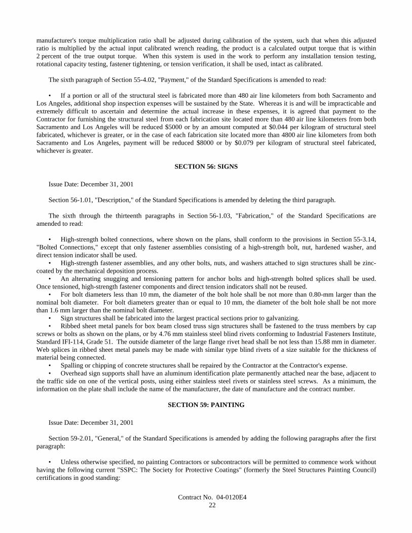
Contract No. 04-0120E422
manufacturer's torque multiplication ratio shall be adjusted during calibration of the system, such that when this adjustedratio is multiplied by the actual input calibrated wrench reading, the product is a calculated output torque that is within2 percent of the true output torque. When this system is used in the work to perform any installation tension testing,rotational capacity testing, fastener tightening, or tension verification, it shall be used, intact as calibrated.
The sixth paragraph of Section 55-4.02, "Payment," of the Standard Specifications is amended to read:
• If a portion or all of the structural steel is fabricated more than 480 air line kilometers from both Sacramento andLos Angeles, additional shop inspection expenses will be sustained by the State. Whereas it is and will be impracticable andextremely difficult to ascertain and determine the actual increase in these expenses, it is agreed that payment to theContractor for furnishing the structural steel from each fabrication site located more than 480 air line kilometers from bothSacramento and Los Angeles will be reduced $5000 or by an amount computed at $0.044 per kilogram of structural steelfabricated, whichever is greater, or in the case of each fabrication site located more than 4800 air line kilometers from bothSacramento and Los Angeles, payment will be reduced $8000 or by $0.079 per kilogram of structural steel fabricated,whichever is greater.
SECTION 56: SIGNS
Issue Date: December 31, 2001
Section 56-1.01, "Description," of the Standard Specifications is amended by deleting the third paragraph.
The sixth through the thirteenth paragraphs in Section 56-1.03, "Fabrication," of the Standard Specifications areamended to read:
• High-strength bolted connections, where shown on the plans, shall conform to the provisions in Section 55-3.14,"Bolted Connections," except that only fastener assemblies consisting of a high-strength bolt, nut, hardened washer, anddirect tension indicator shall be used.
• High-strength fastener assemblies, and any other bolts, nuts, and washers attached to sign structures shall be zinc-coated by the mechanical deposition process.
• An alternating snugging and tensioning pattern for anchor bolts and high-strength bolted splices shall be used.Once tensioned, high-strength fastener components and direct tension indicators shall not be reused.
• For bolt diameters less than 10 mm, the diameter of the bolt hole shall be not more than 0.80-mm larger than thenominal bolt diameter. For bolt diameters greater than or equal to 10 mm, the diameter of the bolt hole shall be not morethan 1.6 mm larger than the nominal bolt diameter.
• Sign structures shall be fabricated into the largest practical sections prior to galvanizing.• Ribbed sheet metal panels for box beam closed truss sign structures shall be fastened to the truss members by cap
screws or bolts as shown on the plans, or by 4.76 mm stainless steel blind rivets conforming to Industrial Fasteners Institute,Standard IFI-114, Grade 51. The outside diameter of the large flange rivet head shall be not less than 15.88 mm in diameter.Web splices in ribbed sheet metal panels may be made with similar type blind rivets of a size suitable for the thickness ofmaterial being connected.
• Spalling or chipping of concrete structures shall be repaired by the Contractor at the Contractor's expense.• Overhead sign supports shall have an aluminum identification plate permanently attached near the base, adjacent to
the traffic side on one of the vertical posts, using either stainless steel rivets or stainless steel screws. As a minimum, theinformation on the plate shall include the name of the manufacturer, the date of manufacture and the contract number.
SECTION 59: PAINTING
Issue Date: December 31, 2001
Section 59-2.01, "General," of the Standard Specifications is amended by adding the following paragraphs after the firstparagraph:
• Unless otherwise specified, no painting Contractors or subcontractors will be permitted to commence work withouthaving the following current "SSPC: The Society for Protective Coatings" (formerly the Steel Structures Painting Council)certifications in good standing:

Contract No. 04-0120E423
A. For cleaning and painting structural steel in the field, certification in conformance with the requirements inQualification Procedure No. 1, "Standard Procedure For Evaluating Painting Contractors (Field Application toComplex Industrial Structures)" (SSPC-QP 1).
B. For removing paint from structural steel, certification in conformance with the requirements in QualificationProcedure No. 2, "Standard Procedure For Evaluating Painting Contractors (Field Removal of Hazardous Coatingsfrom Complex Structures)" (SSPC-QP 2).
C. For cleaning and painting structural steel in a permanent painting facility, certification in conformance with therequirements in Qualification Procedure No. 3, "Standard Procedure For Evaluating Qualifications of Shop PaintingApplicators" (SSPC-QP 3). The AISC's Sophisticated Paint Endorsement (SPE) quality program will be consideredequivalent to SSPC-QP 3.
The third paragraph of Section 59-2.03, "Blast Cleaning," of the Standard Specifications is amended to read:
• Exposed steel or other metal surfaces to be blast cleaned shall be cleaned in conformance with the requirements inSurface Preparation Specification No. 6, "Commercial Blast Cleaning," of the "SSPC: The Society for Protective Coatings."Blast cleaning shall leave all surfaces with a dense, uniform, angular anchor pattern of not less than 35 µm as measured inconformance with the requirements in ASTM Designation: D 4417.
The first paragraph of Section 59-2.06, "Hand Cleaning," of the Standard Specifications is amended to read:
• Dirt, loose rust and mill scale, or paint which is not firmly bonded to the surfaces shall be removed in conformancewith the requirements in Surface Preparation Specification No. 2, "Hand Tool Cleaning," of the "SSPC: The Society forProtective Coatings." Edges of old remaining paint shall be feathered.
The fourth paragraph of Section 59-2.12, "Painting," of the Standard Specifications is amended to read:
• The dry film thickness of the paint will be measured in place with a calibrated Type 2 magnetic film thickness gagein conformance with the requirements of specification SSPC-PA2 of the "SSPC: The Society for Protective Coatings."
SECTION 75: MISCELLANEOUS METAL
Issue Date: December 31, 2001
The table in the tenth paragraph of Section 75-1.02, "Miscellaneous Iron and Steel," of the Standard Specifications isamended to read:
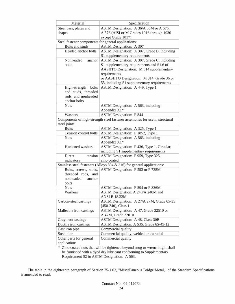
Contract No. 04-0120E424
Material SpecificationSteel bars, plates andshapes
ASTM Designation: A 36/A 36M or A 575,A 576 (AISI or M Grades 1016 through 1030except Grade 1017)
Steel fastener components for general applications:Bolts and studs ASTM Designation: A 307Headed anchor bolts ASTM Designation: A 307, Grade B, including
S1 supplementary requirementsNonheaded anchorbolts
ASTM Designation: A 307, Grade C, includingS1 supplementary requirements and S1.6 ofAASHTO Designation: M 314 supplementaryrequirementsor AASHTO Designation: M 314, Grade 36 or55, including S1 supplementary requirements
High-strength boltsand studs, threadedrods, and nonheadedanchor bolts
ASTM Designation: A 449, Type 1
Nuts ASTM Designation: A 563, includingAppendix X1*
Washers ASTM Designation: F 844Components of high-strength steel fastener assemblies for use in structuralsteel joints:
Bolts ASTM Designation: A 325, Type 1Tension control bolts ASTM Designation: F 1852, Type 1Nuts ASTM Designation: A 563, including
Appendix X1*Hardened washers ASTM Designation: F 436, Type 1, Circular,
including S1 supplementary requirementsDirect tensionindicators
ASTM Designation: F 959, Type 325,zinc-coated
Stainless steel fasteners (Alloys 304 & 316) for general applications:Bolts, screws, studs,threaded rods, andnonheaded anchorbolts
ASTM Designation: F 593 or F 738M
Nuts ASTM Designation: F 594 or F 836MWashers ASTM Designation: A 240/A 240M and
ANSI B 18.22MCarbon-steel castings ASTM Designation: A 27/A 27M, Grade 65-35
[450-240], Class 1Malleable iron castings ASTM Designation: A 47, Grade 32510 or
A 47M, Grade 22010Gray iron castings ASTM Designation: A 48, Class 30BDuctile iron castings ASTM Designation: A 536, Grade 65-45-12Cast iron pipe Commercial qualitySteel pipe Commercial quality, welded or extrudedOther parts for generalapplications
Commercial quality
* Zinc-coated nuts that will be tightened beyond snug or wrench tight shallbe furnished with a dyed dry lubricant conforming to SupplementaryRequirement S2 in ASTM Designation: A 563.
The table in the eighteenth paragraph of Section 75-1.03, "Miscellaneous Bridge Metal," of the Standard Specificationsis amended to read:
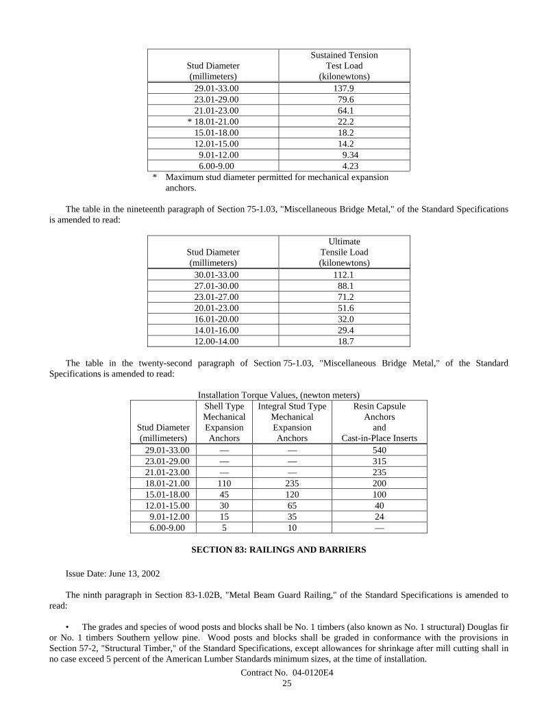
Contract No. 04-0120E425
Stud Diameter(millimeters)
Sustained TensionTest Load
(kilonewtons)29.01-33.00 137.923.01-29.00 79.621.01-23.00 64.1
* 18.01-21.00 22.215.01-18.00 18.212.01-15.00 14.2
9.01-12.00 9.346.00-9.00 4.23
* Maximum stud diameter permitted for mechanical expansionanchors.
The table in the nineteenth paragraph of Section 75-1.03, "Miscellaneous Bridge Metal," of the Standard Specificationsis amended to read:
Stud Diameter(millimeters)
UltimateTensile Load(kilonewtons)
30.01-33.00 112.127.01-30.00 88.123.01-27.00 71.220.01-23.00 51.616.01-20.00 32.014.01-16.00 29.412.00-14.00 18.7
The table in the twenty-second paragraph of Section 75-1.03, "Miscellaneous Bridge Metal," of the StandardSpecifications is amended to read:
Installation Torque Values, (newton meters)
Stud Diameter(millimeters)
Shell TypeMechanicalExpansionAnchors
Integral Stud TypeMechanicalExpansionAnchors
Resin CapsuleAnchors
andCast-in-Place Inserts
29.01-33.00 — — 54023.01-29.00 — — 31521.01-23.00 — — 23518.01-21.00 110 235 20015.01-18.00 45 120 10012.01-15.00 30 65 40 9.01-12.00 15 35 24
6.00-9.00 5 10 —
SECTION 83: RAILINGS AND BARRIERS
Issue Date: June 13, 2002
The ninth paragraph in Section 83-1.02B, "Metal Beam Guard Railing," of the Standard Specifications is amended toread:
• The grades and species of wood posts and blocks shall be No. 1 timbers (also known as No. 1 structural) Douglas firor No. 1 timbers Southern yellow pine. Wood posts and blocks shall be graded in conformance with the provisions inSection 57-2, "Structural Timber," of the Standard Specifications, except allowances for shrinkage after mill cutting shall inno case exceed 5 percent of the American Lumber Standards minimum sizes, at the time of installation.
Contract No. 04-0120E426
The eleventh paragraph in Section 83-1.02B, "Metal Beam Guard Railing," of the Standard Specifications is amended toread:
• Wood posts and blocks shall be pressure treated after fabrication in conformance with the provisions in Section 58,"Preservative Treatment of Lumber, Timber and Piling," of the Standard Specifications with creosote, creosote coal tarsolution, creosote petroleum solution (50-50), pentachlorophenol in hydrocarbon solvent, copper naphthenate, ammoniacalcopper arsenate, or ammoniacal copper zinc arsenate. In addition to the preservatives listed above, Southern yellow pinemay also be pressure treated with chromated copper arsenate. When other than one of the creosote processes is used, blocksshall have a minimum retention of 6.4 Kg/m3, and need not be incised.
SECTION 85: PAVEMENT MARKERS
Issue Date: May 16, 2003
The second through fifth paragraphs in Section 85-1.03, "Sampling, Tolerances and Packaging," of the StandardSpecifications are amended to read:
Sampling• Twenty markers selected at random will constitute a representative sample for each lot of markers.• The lot size shall not exceed 25000 markers.
Tolerances• Three test specimens will be randomly selected from the sample for each test and tested in conformance with these
specifications. Should any one of the 3 specimens fail to conform with the requirements in these specifications, 6 additionalspecimens will be tested. The failure of any one of these 6 specimens shall be cause for rejection of the entire lot orshipment represented by the sample.
• The entire sample of retroreflective pavement markers will be tested for reflectance. The failure of 10 percent ormore of the original sampling shall be cause for rejection.
Section 85-1.04, "Non-Reflective Pavement Markers," of the Standard Specifications is amended to read:
85-1.04 Non-Reflective Pavement Markers• Non-reflective pavement markers (Types A and AY) shall be, at the option of the Contractor, either ceramic or
plastic conforming to these specifications.• The top surface of the marker shall be convex with a gradual change in curvature. The top, bottom and sides shall
be free of objectionable marks or discoloration that will affect adhesion or appearance.• The bottom of markers shall have areas of integrally formed protrusions or indentations, which will increase the
effective bonding surface area of adhesive. The bottom surface of the marker shall not deviate more than 1.5 mm from a flatsurface. The areas of protrusion shall have faces parallel to the bottom of the marker and shall project approximately onemm from the bottom.
The second through fourth paragraphs of Section 85-1.04A, "Non-Reflective Pavement Markers (Ceramic)," of theStandard Specifications are deleted.
The table in the fifth paragraph in Section 85-1.04A, "Non-Reflective Pavement Markers (Ceramic)," of the StandardSpecifications is amended to read:
Testing• Tests shall be performed in conformance with the requirements in California Test 669.
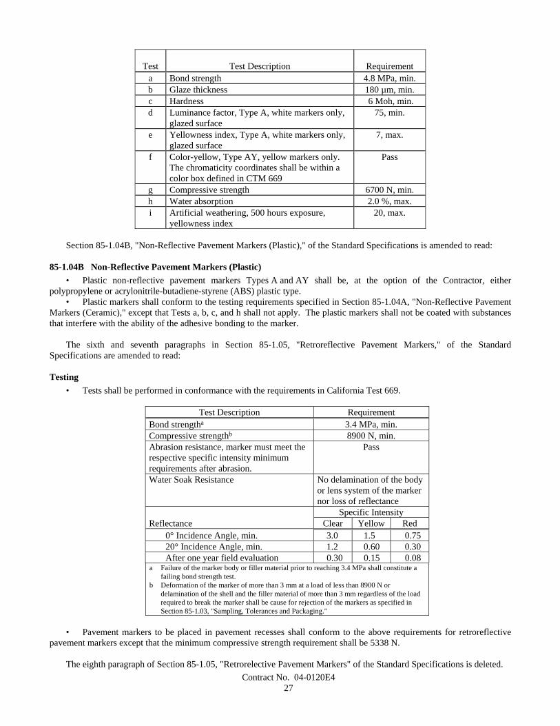
Contract No. 04-0120E427
Test Test Description Requirementa Bond strength 4.8 MPa, min.b Glaze thickness 180 µm, min.c Hardness 6 Moh, min.d Luminance factor, Type A, white markers only,
glazed surface75, min.
e Yellowness index, Type A, white markers only,glazed surface
7, max.
f Color-yellow, Type AY, yellow markers only.The chromaticity coordinates shall be within acolor box defined in CTM 669
Pass
g Compressive strength 6700 N, min.h Water absorption 2.0 %, max.i Artificial weathering, 500 hours exposure,
yellowness index20, max.
Section 85-1.04B, "Non-Reflective Pavement Markers (Plastic)," of the Standard Specifications is amended to read:
85-1.04B Non-Reflective Pavement Markers (Plastic)• Plastic non-reflective pavement markers Types A and AY shall be, at the option of the Contractor, either
polypropylene or acrylonitrile-butadiene-styrene (ABS) plastic type.• Plastic markers shall conform to the testing requirements specified in Section 85-1.04A, "Non-Reflective Pavement
Markers (Ceramic)," except that Tests a, b, c, and h shall not apply. The plastic markers shall not be coated with substancesthat interfere with the ability of the adhesive bonding to the marker.
The sixth and seventh paragraphs in Section 85-1.05, "Retroreflective Pavement Markers," of the StandardSpecifications are amended to read:
Testing• Tests shall be performed in conformance with the requirements in California Test 669.
Test Description RequirementBond strengtha 3.4 MPa, min.Compressive strengthb 8900 N, min.Abrasion resistance, marker must meet therespective specific intensity minimumrequirements after abrasion.
Pass
Water Soak Resistance No delamination of the bodyor lens system of the markernor loss of reflectance
Specific IntensityReflectance Clear Yellow Red
0° Incidence Angle, min. 3.0 1.5 0.7520° Incidence Angle, min. 1.2 0.60 0.30After one year field evaluation 0.30 0.15 0.08
a Failure of the marker body or filler material prior to reaching 3.4 MPa shall constitute afailing bond strength test.
b Deformation of the marker of more than 3 mm at a load of less than 8900 N ordelamination of the shell and the filler material of more than 3 mm regardless of the loadrequired to break the marker shall be cause for rejection of the markers as specified inSection 85-1.03, "Sampling, Tolerances and Packaging."
• Pavement markers to be placed in pavement recesses shall conform to the above requirements for retroreflectivepavement markers except that the minimum compressive strength requirement shall be 5338 N.
The eighth paragraph of Section 85-1.05, "Retrorelective Pavement Markers" of the Standard Specifications is deleted.
Contract No. 04-0120E428
The eighth paragraph in Section 85-1.06, "Replacement," of the Standard Specifications is amended to read:
• Epoxy adhesive shall not be used to apply non-reflective plastic pavement markers.
SECTION 86: SIGNALS, LIGHTING AND ELECTRICAL SYSTEMS
Issue Date: June 19, 2003
The seventh paragraph of Section 86-2.03, "Foundations," of the Standard Specifications is amended to read:
• Forms shall be true to line and grade. Tops of foundations for posts and standards, except special foundations, shallbe finished to curb or sidewalk grade or as directed by the Engineer. Forms shall be rigid and securely braced in place.Conduit ends and anchor bolts shall be placed in proper position and to proper height, and anchor bolts shall be held in placeby means of rigid top and bottom templates. The bottom template shall be made of steel. The bottom template shall provideproper spacing and alignment of the anchor bolts near their bottom embedded end. The bottom template shall be installedbefore placing footing concrete. Anchor bolts shall not be installed more than 1:40 from vertical.
Section 86-2.03, "Foundations," of the Standard Specifications is amended by deleting the eighth paragraph.
The twelfth paragraph of Section 86-2.03, "Foundations," of the Standard Specifications is amended to read:
• Plumbing of the standards shall be accomplished by adjusting the leveling nuts before placing the mortar or beforethe foundation is finished to final grade. Shims, or other similar devices shall not be used for plumbing or raking of posts,standards or pedestals. After final adjustments of both top nuts and leveling nuts on anchorage assemblies have been made,firm contact shall exist between all bearing surfaces of the anchor bolt nuts, washers, and the base plate.
The first paragraph of Section 86-2.04, "Standards, Steel Pedestals and Posts," of the Standard Specifications is amendedto read:
• Standards for traffic signals and lighting, and steel pedestals for cabinets and other similar equipment, shall belocated as shown on the plans. Bolts, nuts and washers, and anchor bolts for use in signal and lighting support structuresshall conform to the provisions in Section 55-2, "Materials." Except when bearing-type connections or slipbases arespecified, high-strength bolted connections shall conform to the provisions in Section 55-3.14, "Bolted Connections."Welding, nondestructive testing (NDT) of welds, and acceptance and repair criteria for NDT of steel members shall conformto the requirements of AWS D1.1 and the contract special provisions.
The second paragraph of Section 86-2.04, "Standards, Steel Pedestals and Posts," of the Standard Specifications isamended to read:
• On each lighting standard except Type 1, one rectangular corrosion resistant metal identification tag shall bepermanently attached above the hand hole, near the base of the standard, using stainless steel rivets. On each signal polesupport, two corrosion resistant metal identification tags shall be attached, one above the hand hole near the base of thevertical standard and one on the underside of the signal mast arm near the arm plate. As a minimum, the information on eachidentification tag shall include the name of the manufacturer, the date of manufacture, the identification number as shown onthe plans, the contract number, and a unique identification code assigned by the fabricator. This number shall be traceable toa particular contract and the welds on that component, and shall be readable after the support structure is coated andinstalled. The lettering shall be a minimum of 7 mm high. The information may be either depressed or raised, and shall belegible.
The fourth paragraph of Section 86-2.04, "Standards, Steel Pedestals and Posts" of the Standard Specifications isamended to read:
• Ferrous metal parts of standards, with shaft length of 4.6 m and longer, shall conform to the details shown on theplans, the provisions in Section 55, "Steel Structures," except as otherwise noted, and the following requirements:
Contract No. 04-0120E429
Except as otherwise specified, standards shall be fabricated from sheet steel of weldable grade having a minimumyield strength, after fabrication, of 276 MPa.
Certified test reports which verify conformance to the minimum yield strength requirements shall be submitted tothe Engineer. The test reports may be the mill test reports for the as-received steel or, when the as-received steel has alower yield strength than required, the Contractor shall provide supportive test data which provides assurance that theContractor's method of cold forming will consistently increase the tensile properties of the steel to meet the specifiedminimum yield strength. The supportive test data shall include tensile properties of the steel after cold forming forspecific heats and thicknesses.
When a single-ply 8-mm thick pole is specified, a 2-ply pole with equivalent section modulus may be substituted.Standards may be fabricated of full-length sheets or shorter sections. Each section shall be fabricated from not more
than 2 pieces of sheet steel. Where 2 pieces are used, the longitudinal welded seams shall be directly opposite oneanother. When the sections are butt-welded together, the longitudinal welded seams on adjacent sections shall be placedto form continuous straight seams from base to top of standard.
Butt-welded circumferential joints of tubular sections requiring CJP groove welds shall be made using a metalsleeve backing ring inside each joint. The sleeve shall be 3-mm nominal thickness, or thicker, and manufactured fromsteel having the same chemical composition as the steel in the tubular sections to be joined. When the sections to bejoined have different specified minimum yield strengths, the steel in the sleeve shall have the same chemicalcomposition as the tubular section having the higher minimum yield strength. The width of the metal sleeve shall beconsistent with the type of NDT chosen and shall be a minimum width of 25 mm. The sleeve shall be centered at thejoint and be in contact with the tubular section at the point of the weld at time of fit-up.
Welds shall be continuous.The weld metal at the transverse joint shall extend to the sleeve, making the sleeve an integral part of the joint.During fabrication, longitudinal seams on vertical tubular members of cantilevered support structures shall be
centered on and along the side of the pole that the pole plate is located. Longitudinal seams on horizontal tubularmembers, including signal and luminaire arms, shall be within +/-45 degrees of the bottom of the arm.
The longitudinal welds in steel tubular sections may be made by the electric resistance welding process.Longitudinal seam welds shall have 60 percent minimum penetration, except that within 150 mm of circumferential
welds, longitudinal seam welds shall be CJP groove welds. In addition, longitudinal seam welds on lighting supportstructures having telescopic pole segment splices shall be CJP groove welds on the female end for a length on each endequal to the designated slip fit splice length plus 150 mm.
Exposed circumferential welds, except fillet and fatigue-resistant welds, shall be ground flush (-0, +2mm) with thebase metal prior to galvanizing or painting.
Circumferential welds and base plate-to-pole welds may be repaired only one time without written permission fromthe Engineer.
Exposed edges of the plates that make up the base assembly shall be finished smooth and exposed corners of theplates shall be broken unless otherwise shown on the plans. Shafts shall be provided with slip-fitter shaft caps.
Flatness of surfaces of 1) base plates that are to come in contact with concrete, grout, or washers and leveling nuts2) plates in high-strength bolted connections, 3) plates in joints where cap screws are used to secure luminaire and signalarms, and 4) plates used for breakaway slip base assemblies shall conform to the requirements of ASTM A6.
Standards shall be straight, with a permissive variation not to exceed 25 mm measured at the midpoint of a 9-m or11-m standard and not to exceed 20 mm measured at the midpoint of a 5-m through 6-m standard. Variation shall notexceed 25 mm at a point 4.5 m above the base plate for Type 35 and Type 36 standards.
Zinc-coated nuts used on fastener assemblies having a specified preload (obtained by specifying a prescribedtension, torque value, or degree of turn) shall be provided with a colored lubricant that is clean and dry to the touch. Thecolor of the lubricant shall be in contrast to the zinc coating on the nut so that the presence of the lubricant is visuallyobvious. In addition, either the lubricant shall be insoluble in water, or fastener components shall be shipped to the jobsite in a sealed container.
No holes shall be made in structural members unless the holes are shown on the plans or are approved in writing bythe Engineer.
Standards with an outside diameter of 300 mm or less shall be round. Standards with an outside diameter greaterthan 300 mm shall be round or multisided. Multisided standards shall have a minimum of 12 sides which shall beconvex and shall have a minimum bend radius of 100 mm.
Mast arms for standards shall be fabricated from material as specified for standards, and shall conform to thedimensions shown on the plans.
The cast steel option for slip bases shall be fabricated from material conforming to the requirements in ASTMDesignation: A 27/A 27M, Grade 70-40. Other comparable material may be used if written permission is given by theEngineer. The casting tolerances shall be in conformance with the Steel Founder's Society of America recommendations(green sand molding).
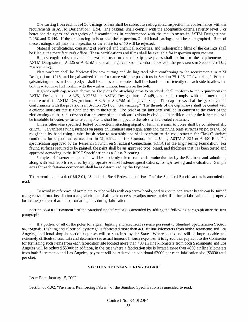
Contract No. 04-0120E430
One casting from each lot of 50 castings or less shall be subject to radiographic inspection, in conformance with therequirements in ASTM Designation: E 94. The castings shall comply with the acceptance criteria severity level 3 orbetter for the types and categories of discontinuities in conformance with the requirements in ASTM Designations:E 186 and E 446. If the one casting fails to pass the inspection, 2 additional castings shall be radiographed. Both ofthese castings shall pass the inspection or the entire lot of 50 will be rejected.
Material certifications, consisting of physical and chemical properties, and radiographic films of the castings shallbe filed at the manufacturer's office. These certifications and films shall be available for inspection upon request.
High-strength bolts, nuts and flat washers used to connect slip base plates shall conform to the requirements inASTM Designation: A 325 or A 325M and shall be galvanized in conformance with the provisions in Section 75-1.05,"Galvanizing."
Plate washers shall be fabricated by saw cutting and drilling steel plate conforming to the requirements in AISIDesignation: 1018, and be galvanized in conformance with the provisions in Section 75-1.05, "Galvanizing." Prior togalvanizing, burrs and sharp edges shall be removed and holes shall be chamfered sufficiently on each side to allow thebolt head to make full contact with the washer without tension on the bolt.
High-strength cap screws shown on the plans for attaching arms to standards shall conform to the requirements inASTM Designation: A 325, A 325M or ASTM Designation: A 449, and shall comply with the mechanicalrequirements in ASTM Designation: A 325 or A 325M after galvanizing. The cap screws shall be galvanized inconformance with the provisions in Section 75-1.05, "Galvanizing." The threads of the cap screws shall be coated witha colored lubricant that is clean and dry to the touch. The color of the lubricant shall be in contrast to the color of thezinc coating on the cap screw so that presence of the lubricant is visually obvious. In addition, either the lubricant shallbe insoluble in water, or fastener components shall be shipped to the job site in a sealed container.
Unless otherwise specified, bolted connections attaching signal or luminaire arms to poles shall be considered slipcritical. Galvanized faying surfaces on plates on luminaire and signal arms and matching plate surfaces on poles shall beroughened by hand using a wire brush prior to assembly and shall conform to the requirements for Class C surfaceconditions for slip-critical connections in "Specification for Structural Joints Using ASTM A 325 or A 490 Bolts," aspecification approved by the Research Council on Structural Connections (RCSC) of the Engineering Foundation. Forfaying surfaces required to be painted, the paint shall be an approved type, brand, and thickness that has been tested andapproved according to the RCSC Specification as a Class B coating.
Samples of fastener components will be randomly taken from each production lot by the Engineer and submitted,along with test reports required by appropriate ASTM fastener specifications, for QA testing and evaluation. Samplesizes for each fastener component shall be as determined by the Engineer.
The seventh paragraph of 86-2.04, "Standards, Steel Pedestals and Posts" of the Standard Specifications is amended toread:
• To avoid interference of arm plate-to-tube welds with cap screw heads, and to ensure cap screw heads can be turnedusing conventional installation tools, fabricators shall make necessary adjustments to details prior to fabrication and properlylocate the position of arm tubes on arm plates during fabrication.
Section 86-8.01, "Payment," of the Standard Specifications is amended by adding the following paragraph after the firstparagraph:
• If a portion or all of the poles for signal, lighting and electrical systems pursuant to Standard Specification Section86, "Signals, Lighting and Electrical Systems," is fabricated more than 480 air line kilometers from both Sacramento and LosAngeles, additional shop inspection expenses will be sustained by the State. Whereas it is and will be impracticable andextremely difficult to ascertain and determine the actual increase in such expenses, it is agreed that payment to the Contractorfor furnishing such items from each fabrication site located more than 480 air line kilometers from both Sacramento and LosAngeles will be reduced $5000; in addition, in the case where a fabrication site is located more than 4800 air line kilometersfrom both Sacramento and Los Angeles, payment will be reduced an additional $3000 per each fabrication site ($8000 totalper site).
SECTION 88: ENGINEERING FABRIC
Issue Date: January 15, 2002
Section 88-1.02, "Pavement Reinforcing Fabric," of the Standard Specifications is amended to read:
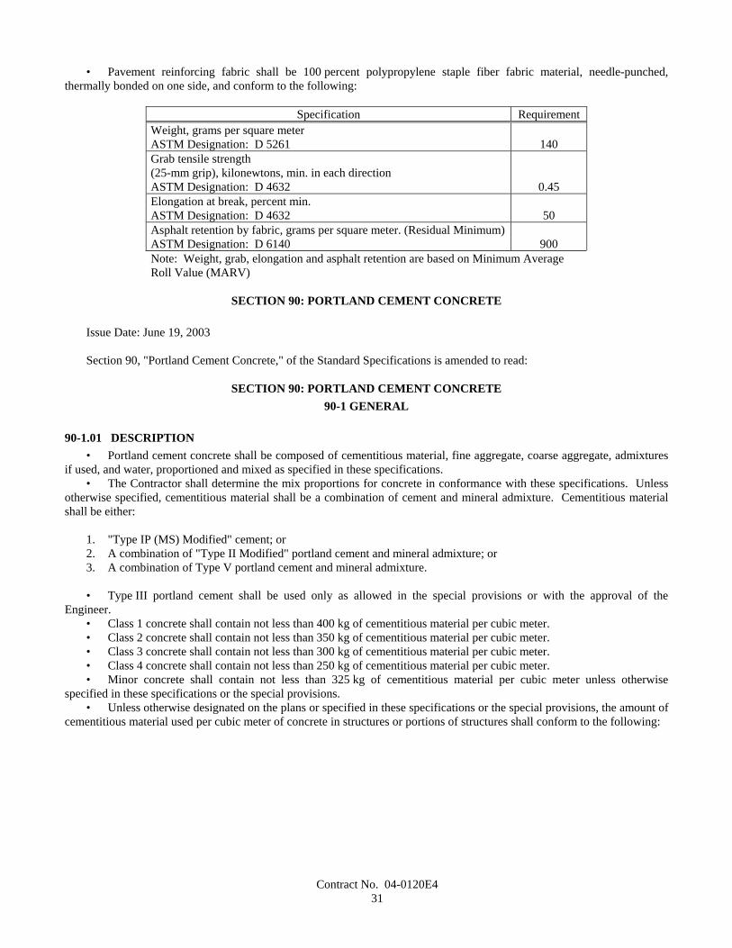
Contract No. 04-0120E431
• Pavement reinforcing fabric shall be 100 percent polypropylene staple fiber fabric material, needle-punched,thermally bonded on one side, and conform to the following:
Specification RequirementWeight, grams per square meterASTM Designation: D 5261 140Grab tensile strength(25-mm grip), kilonewtons, min. in each directionASTM Designation: D 4632 0.45Elongation at break, percent min.ASTM Designation: D 4632 50Asphalt retention by fabric, grams per square meter. (Residual Minimum)ASTM Designation: D 6140 900Note: Weight, grab, elongation and asphalt retention are based on Minimum AverageRoll Value (MARV)
SECTION 90: PORTLAND CEMENT CONCRETE
Issue Date: June 19, 2003
Section 90, "Portland Cement Concrete," of the Standard Specifications is amended to read:
SECTION 90: PORTLAND CEMENT CONCRETE90-1 GENERAL
90-1.01 DESCRIPTION• Portland cement concrete shall be composed of cementitious material, fine aggregate, coarse aggregate, admixtures
if used, and water, proportioned and mixed as specified in these specifications.• The Contractor shall determine the mix proportions for concrete in conformance with these specifications. Unless
otherwise specified, cementitious material shall be a combination of cement and mineral admixture. Cementitious materialshall be either:
1. "Type IP (MS) Modified" cement; or2. A combination of "Type II Modified" portland cement and mineral admixture; or3. A combination of Type V portland cement and mineral admixture.
• Type III portland cement shall be used only as allowed in the special provisions or with the approval of theEngineer.
• Class 1 concrete shall contain not less than 400 kg of cementitious material per cubic meter.• Class 2 concrete shall contain not less than 350 kg of cementitious material per cubic meter.• Class 3 concrete shall contain not less than 300 kg of cementitious material per cubic meter.• Class 4 concrete shall contain not less than 250 kg of cementitious material per cubic meter.• Minor concrete shall contain not less than 325 kg of cementitious material per cubic meter unless otherwise
specified in these specifications or the special provisions.• Unless otherwise designated on the plans or specified in these specifications or the special provisions, the amount of
cementitious material used per cubic meter of concrete in structures or portions of structures shall conform to the following:
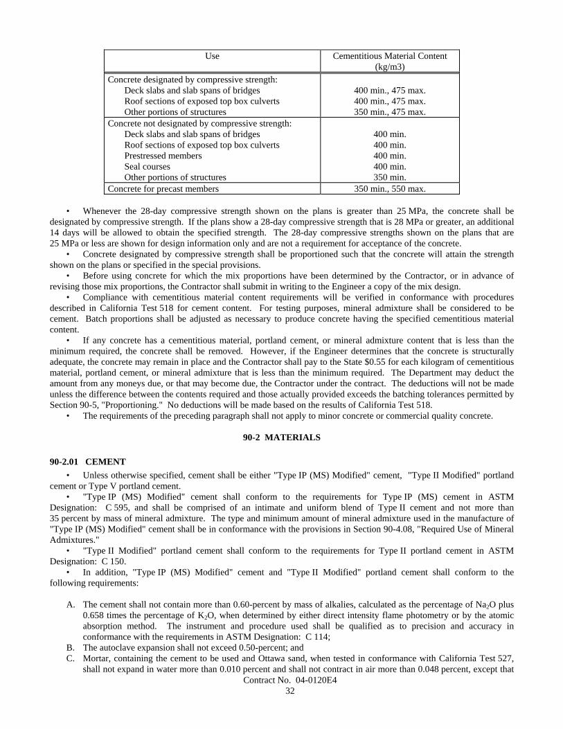
Contract No. 04-0120E432
Use Cementitious Material Content(kg/m3)
Concrete designated by compressive strength:Deck slabs and slab spans of bridgesRoof sections of exposed top box culvertsOther portions of structures
400 min., 475 max.400 min., 475 max.350 min., 475 max.
Concrete not designated by compressive strength:Deck slabs and slab spans of bridgesRoof sections of exposed top box culvertsPrestressed membersSeal coursesOther portions of structures
400 min.400 min.400 min.400 min.350 min.
Concrete for precast members 350 min., 550 max.
• Whenever the 28-day compressive strength shown on the plans is greater than 25 MPa, the concrete shall bedesignated by compressive strength. If the plans show a 28-day compressive strength that is 28 MPa or greater, an additional14 days will be allowed to obtain the specified strength. The 28-day compressive strengths shown on the plans that are25 MPa or less are shown for design information only and are not a requirement for acceptance of the concrete.
• Concrete designated by compressive strength shall be proportioned such that the concrete will attain the strengthshown on the plans or specified in the special provisions.
• Before using concrete for which the mix proportions have been determined by the Contractor, or in advance ofrevising those mix proportions, the Contractor shall submit in writing to the Engineer a copy of the mix design.
• Compliance with cementitious material content requirements will be verified in conformance with proceduresdescribed in California Test 518 for cement content. For testing purposes, mineral admixture shall be considered to becement. Batch proportions shall be adjusted as necessary to produce concrete having the specified cementitious materialcontent.
• If any concrete has a cementitious material, portland cement, or mineral admixture content that is less than theminimum required, the concrete shall be removed. However, if the Engineer determines that the concrete is structurallyadequate, the concrete may remain in place and the Contractor shall pay to the State $0.55 for each kilogram of cementitiousmaterial, portland cement, or mineral admixture that is less than the minimum required. The Department may deduct theamount from any moneys due, or that may become due, the Contractor under the contract. The deductions will not be madeunless the difference between the contents required and those actually provided exceeds the batching tolerances permitted bySection 90-5, "Proportioning." No deductions will be made based on the results of California Test 518.
• The requirements of the preceding paragraph shall not apply to minor concrete or commercial quality concrete.
90-2 MATERIALS
90-2.01 CEMENT• Unless otherwise specified, cement shall be either "Type IP (MS) Modified" cement, "Type II Modified" portland
cement or Type V portland cement.• "Type IP (MS) Modified" cement shall conform to the requirements for Type IP (MS) cement in ASTM
Designation: C 595, and shall be comprised of an intimate and uniform blend of Type II cement and not more than35 percent by mass of mineral admixture. The type and minimum amount of mineral admixture used in the manufacture of"Type IP (MS) Modified" cement shall be in conformance with the provisions in Section 90-4.08, "Required Use of MineralAdmixtures."
• "Type II Modified" portland cement shall conform to the requirements for Type II portland cement in ASTMDesignation: C 150.
• In addition, "Type IP (MS) Modified" cement and "Type II Modified" portland cement shall conform to thefollowing requirements:
A. The cement shall not contain more than 0.60-percent by mass of alkalies, calculated as the percentage of Na2O plus0.658 times the percentage of K2O, when determined by either direct intensity flame photometry or by the atomicabsorption method. The instrument and procedure used shall be qualified as to precision and accuracy inconformance with the requirements in ASTM Designation: C 114;
B. The autoclave expansion shall not exceed 0.50-percent; andC. Mortar, containing the cement to be used and Ottawa sand, when tested in conformance with California Test 527,
shall not expand in water more than 0.010 percent and shall not contract in air more than 0.048 percent, except that

Contract No. 04-0120E433
when cement is to be used for precast prestressed concrete piling, precast prestressed concrete members, or steamcured concrete products, the mortar shall not contract in air more than 0.053 percent.
• Type III and Type V portland cements shall conform to the requirements in ASTM Designation: C 150 and theadditional requirements listed above for "Type II Modified" portland cement, except that when tested in conformance withCalifornia Test 527, mortar containing Type III portland cement shall not contract in air more than 0.075 percent.
• Cement used in the manufacture of cast-in-place concrete for exposed surfaces of like elements of a structure shallbe from the same cement mill.
• Cement shall be protected from exposure to moisture until used. Sacked cement shall be piled to permit access fortally, inspection, and identification of each shipment.
• Adequate facilities shall be provided to assure that cement meeting the provisions specified in this Section 90-2.01shall be kept separate from other cement in order to prevent any but the specified cement from entering the work. Safe andsuitable facilities for sampling cement shall be provided at the weigh hopper or in the feed line immediately in advance of thehopper, in conformance with California Test 125.
• If cement is used prior to sampling and testing as provided in Section 6-1.07, "Certificates of Compliance," and thecement is delivered directly to the site of the work, the Certificate of Compliance shall be signed by the cement manufactureror supplier of the cement. If the cement is used in ready-mixed concrete or in precast concrete products purchased as such bythe Contractor, the Certificate of Compliance shall be signed by the manufacturer of the concrete or product.
• Cement furnished without a Certificate of Compliance shall not be used in the work until the Engineer has hadsufficient time to make appropriate tests and has approved the cement for use.
90-2.02 AGGREGATES• Aggregates shall be free from deleterious coatings, clay balls, roots, bark, sticks, rags, and other extraneous
material.• Natural aggregates shall be thoroughly and uniformly washed before use.• The Contractor, at the Contractor's expense, shall provide safe and suitable facilities, including necessary splitting
devices for obtaining samples of aggregates, in conformance with California Test 125.• Aggregates shall be of such character that it will be possible to produce workable concrete within the limits of water
content provided in Section 90-6.06, "Amount of Water and Penetration."• Aggregates shall have not more than 10 percent loss when tested for soundness in conformance with the
requirements in California Test 214. The soundness requirement for fine aggregate will be waived, provided that thedurability index, Df, of the fine aggregate is 60, or greater, when tested for durability in conformance with CaliforniaTest 229.
• If the results of any one or more of the Cleanness Value, Sand Equivalent, or aggregate grading tests do not meetthe requirements specified for "Operating Range" but all meet the "Contract Compliance" requirements, the placement ofconcrete shall be suspended at the completion of the current pour until tests or other information indicate that the nextmaterial to be used in the work will comply with the requirements specified for "Operating Range."
• If the results of either or both the Cleanness Value and coarse aggregate grading tests do not meet the requirementsspecified for "Contract Compliance," the concrete that is represented by the tests shall be removed. However, if the Engineerdetermines that the concrete is structurally adequate, the concrete may remain in place, and the Contractor shall pay to theState $4.60 per cubic meter for paving concrete and $7.20 per cubic meter for all other concrete for the concrete representedby these tests and left in place. The Department may deduct the amount from any moneys due, or that may become due, theContractor under the contract.
• If the results of either or both the Sand Equivalent and fine aggregate grading tests do not meet the requirementsspecified for "Contract Compliance," the concrete which is represented by the tests shall be removed. However, if theEngineer determines that the concrete is structurally adequate, the concrete may remain in place, and the Contractor shall payto the State $4.60 per cubic meter for paving concrete and $7.20 per cubic meter for all other concrete for the concreterepresented by these tests and left in place. The Department may deduct the amount from any moneys due, or that maybecome due, the Contractor under the contract.
• The 2 preceding paragraphs apply individually to the "Contract Compliance" requirements for coarse aggregate andfine aggregate. When both coarse aggregate and fine aggregate do not conform to the "Contract Compliance" requirements,both paragraphs shall apply. The payments specified in those paragraphs shall be in addition to any payments made inconformance with the provisions in Section 90-1.01, "Description."
• No single Cleanness Value, Sand Equivalent or aggregate grading test shall represent more than 250 m3 of concreteor one day's pour, whichever is smaller.
• When the source of an aggregate is changed, the Contractor shall adjust the mix proportions and submit in writingto the Engineer a copy of the mix design before using the aggregates.
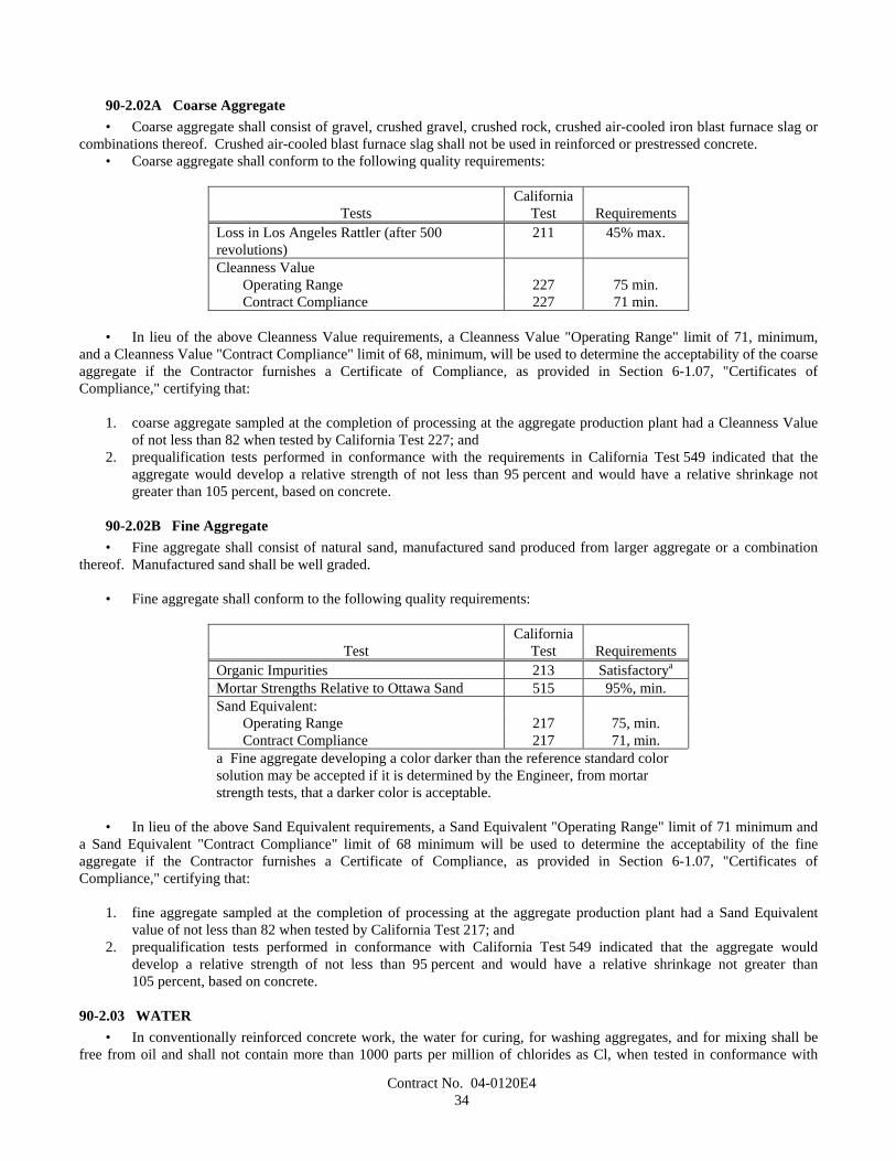
Contract No. 04-0120E434
90-2.02A Coarse Aggregate• Coarse aggregate shall consist of gravel, crushed gravel, crushed rock, crushed air-cooled iron blast furnace slag or
combinations thereof. Crushed air-cooled blast furnace slag shall not be used in reinforced or prestressed concrete.• Coarse aggregate shall conform to the following quality requirements:
TestsCalifornia
Test RequirementsLoss in Los Angeles Rattler (after 500revolutions)
211 45% max.
Cleanness ValueOperating Range 227 75 min.Contract Compliance 227 71 min.
• In lieu of the above Cleanness Value requirements, a Cleanness Value "Operating Range" limit of 71, minimum,and a Cleanness Value "Contract Compliance" limit of 68, minimum, will be used to determine the acceptability of the coarseaggregate if the Contractor furnishes a Certificate of Compliance, as provided in Section 6-1.07, "Certificates ofCompliance," certifying that:
1. coarse aggregate sampled at the completion of processing at the aggregate production plant had a Cleanness Valueof not less than 82 when tested by California Test 227; and
2. prequalification tests performed in conformance with the requirements in California Test 549 indicated that theaggregate would develop a relative strength of not less than 95 percent and would have a relative shrinkage notgreater than 105 percent, based on concrete.
90-2.02B Fine Aggregate• Fine aggregate shall consist of natural sand, manufactured sand produced from larger aggregate or a combination
thereof. Manufactured sand shall be well graded.
• Fine aggregate shall conform to the following quality requirements:
TestCalifornia
Test RequirementsOrganic Impurities 213 Satisfactorya
Mortar Strengths Relative to Ottawa Sand 515 95%, min.Sand Equivalent:
Operating Range 217 75, min.Contract Compliance 217 71, min.
a Fine aggregate developing a color darker than the reference standard colorsolution may be accepted if it is determined by the Engineer, from mortarstrength tests, that a darker color is acceptable.
• In lieu of the above Sand Equivalent requirements, a Sand Equivalent "Operating Range" limit of 71 minimum anda Sand Equivalent "Contract Compliance" limit of 68 minimum will be used to determine the acceptability of the fineaggregate if the Contractor furnishes a Certificate of Compliance, as provided in Section 6-1.07, "Certificates ofCompliance," certifying that:
1. fine aggregate sampled at the completion of processing at the aggregate production plant had a Sand Equivalentvalue of not less than 82 when tested by California Test 217; and
2. prequalification tests performed in conformance with California Test 549 indicated that the aggregate woulddevelop a relative strength of not less than 95 percent and would have a relative shrinkage not greater than105 percent, based on concrete.
90-2.03 WATER• In conventionally reinforced concrete work, the water for curing, for washing aggregates, and for mixing shall be
free from oil and shall not contain more than 1000 parts per million of chlorides as Cl, when tested in conformance with
Contract No. 04-0120E435
California Test 422, nor more than 1300 parts per million of sulfates as SO4, when tested in conformance with CaliforniaTest 417. In prestressed concrete work, the water for curing, for washing aggregates, and for mixing shall be free from oiland shall not contain more than 650 parts per million of chlorides as Cl, when tested in conformance with CaliforniaTest 422, nor more than 1300 parts per million of sulfates as SO4, when tested in conformance with California Test 417. Inno case shall the water contain an amount of impurities that will cause either: 1) a change in the setting time of cement ofmore than 25 percent when tested in conformance with the requirements in ASTM Designation: C 191 or ASTMDesignation: C 266 or 2) a reduction in the compressive strength of mortar at 14 days of more than 5 percent, when tested inconformance with the requirements in ASTM Designation: C 109, when compared to the results obtained with distilledwater or deionized water, tested in conformance with the requirements in ASTM Designation: C 109.
• In non-reinforced concrete work, the water for curing, for washing aggregates and for mixing shall be free from oiland shall not contain more than 2000 parts per million of chlorides as Cl, when tested in conformance with CaliforniaTest 422, or more than 1500 parts per million of sulfates as SO4, when tested in conformance with California Test 417.
• In addition to the above provisions, water for curing concrete shall not contain impurities in a sufficient amount tocause discoloration of the concrete or produce etching of the surface.
• Water reclaimed from mixer wash-out operations may be used in mixing concrete. The water shall not containcoloring agents or more than 300 parts per million of alkalis (Na2O + 0.658 K2O) as determined on the filtrate. The specificgravity of the water shall not exceed 1.03 and shall not vary more than ±0.010 during a day's operations.
90-2.04 ADMIXTURE MATERIALS• Admixture materials shall conform to the requirements in the following ASTM Designations:
A. Chemical Admixtures—ASTM Designation: C 494.B. Air-entraining Admixtures—ASTM Designation: C 260.C. Calcium Chloride—ASTM Designation: D 98.D. Mineral Admixtures—Coal fly ash; raw or calcined natural pozzolan as specified in ASTM Designation: C 618;
silica fume conforming to the requirements in ASTM Designation: C 1240, with reduction of mortar expansion of80 percent, minimum, using the cement from the proposed mix design.
• Unless otherwise specified in the special provisions, mineral admixtures shall be used in conformance with theprovisions in Section 90-4.08, "Required Use of Mineral Admixtures."
90-3 AGGREGATE GRADINGS
90-3.01 GENERAL• Before beginning concrete work, the Contractor shall submit in writing to the Engineer the gradation of the primary
aggregate nominal sizes that the Contractor proposes to furnish. If a primary coarse aggregate or the fine aggregate isseparated into 2 or more sizes, the proposed gradation shall consist of the gradation for each individual size, and theproposed proportions of each individual size, combined mathematically to indicate one proposed gradation. The proposedgradation shall meet the grading requirements shown in the table in this section, and shall show the percentage passing eachof the sieve sizes used in determining the end result.
• The Engineer may waive, in writing, the gradation requirements in this Section 90-3.01 and in Sections 90-3.02,"Coarse Aggregate Grading," 90-3.03, "Fine Aggregate Grading," and 90-3.04, "Combined Aggregate Gradings," if, in theEngineer's opinion, furnishing the gradation is not necessary for the type or amount of concrete work to be constructed.
• Gradations proposed by the Contractor shall be within the following percentage passing limits:
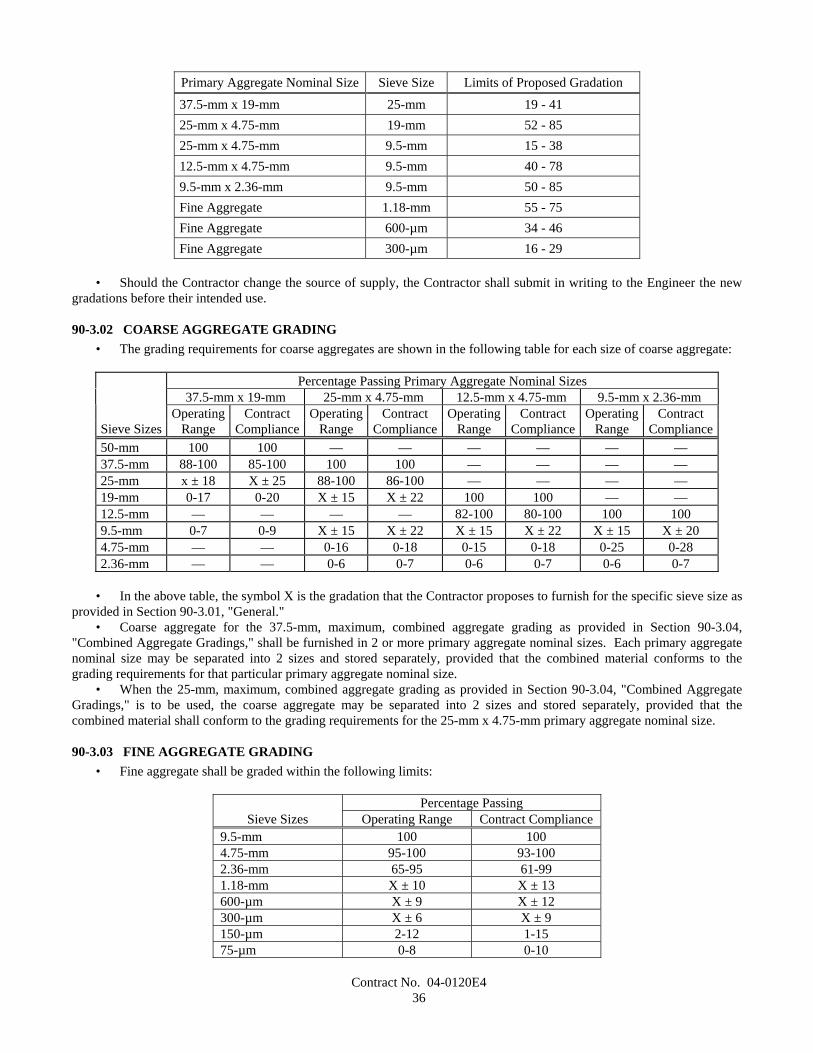
Contract No. 04-0120E436
Primary Aggregate Nominal Size Sieve Size Limits of Proposed Gradation
37.5-mm x 19-mm 25-mm 19 - 4125-mm x 4.75-mm 19-mm 52 - 8525-mm x 4.75-mm 9.5-mm 15 - 3812.5-mm x 4.75-mm 9.5-mm 40 - 789.5-mm x 2.36-mm 9.5-mm 50 - 85Fine Aggregate 1.18-mm 55 - 75Fine Aggregate 600-µm 34 - 46Fine Aggregate 300-µm 16 - 29
• Should the Contractor change the source of supply, the Contractor shall submit in writing to the Engineer the newgradations before their intended use.
90-3.02 COARSE AGGREGATE GRADING• The grading requirements for coarse aggregates are shown in the following table for each size of coarse aggregate:
Percentage Passing Primary Aggregate Nominal Sizes37.5-mm x 19-mm 25-mm x 4.75-mm 12.5-mm x 4.75-mm 9.5-mm x 2.36-mm
Operating Contract Operating Contract Operating Contract Operating ContractSieve Sizes Range Compliance Range Compliance Range Compliance Range Compliance50-mm 100 100 — — — — — —37.5-mm 88-100 85-100 100 100 — — — —25-mm x ± 18 X ± 25 88-100 86-100 — — — —19-mm 0-17 0-20 X ± 15 X ± 22 100 100 — —12.5-mm — — — — 82-100 80-100 100 1009.5-mm 0-7 0-9 X ± 15 X ± 22 X ± 15 X ± 22 X ± 15 X ± 204.75-mm — — 0-16 0-18 0-15 0-18 0-25 0-282.36-mm — — 0-6 0-7 0-6 0-7 0-6 0-7
• In the above table, the symbol X is the gradation that the Contractor proposes to furnish for the specific sieve size asprovided in Section 90-3.01, "General."
• Coarse aggregate for the 37.5-mm, maximum, combined aggregate grading as provided in Section 90-3.04,"Combined Aggregate Gradings," shall be furnished in 2 or more primary aggregate nominal sizes. Each primary aggregatenominal size may be separated into 2 sizes and stored separately, provided that the combined material conforms to thegrading requirements for that particular primary aggregate nominal size.
• When the 25-mm, maximum, combined aggregate grading as provided in Section 90-3.04, "Combined AggregateGradings," is to be used, the coarse aggregate may be separated into 2 sizes and stored separately, provided that thecombined material shall conform to the grading requirements for the 25-mm x 4.75-mm primary aggregate nominal size.
90-3.03 FINE AGGREGATE GRADING• Fine aggregate shall be graded within the following limits:
Percentage PassingSieve Sizes Operating Range Contract Compliance
9.5-mm 100 1004.75-mm 95-100 93-1002.36-mm 65-95 61-991.18-mm X ± 10 X ± 13600-µm X ± 9 X ± 12300-µm X ± 6 X ± 9150-µm 2-12 1-1575-µm 0-8 0-10
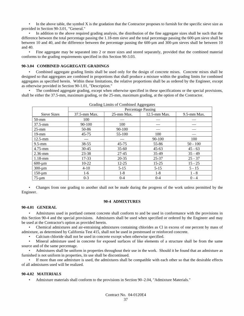
Contract No. 04-0120E437
• In the above table, the symbol X is the gradation that the Contractor proposes to furnish for the specific sieve size asprovided in Section 90-3.01, "General."
• In addition to the above required grading analysis, the distribution of the fine aggregate sizes shall be such that thedifference between the total percentage passing the 1.18-mm sieve and the total percentage passing the 600-µm sieve shall bebetween 10 and 40, and the difference between the percentage passing the 600-µm and 300-µm sieves shall be between 10and 40.
• Fine aggregate may be separated into 2 or more sizes and stored separately, provided that the combined materialconforms to the grading requirements specified in this Section 90-3.03.
90-3.04 COMBINED AGGREGATE GRADINGS• Combined aggregate grading limits shall be used only for the design of concrete mixes. Concrete mixes shall be
designed so that aggregates are combined in proportions that shall produce a mixture within the grading limits for combinedaggregates as specified herein. Within these limitations, the relative proportions shall be as ordered by the Engineer, exceptas otherwise provided in Section 90-1.01, "Description."
• The combined aggregate grading, except when otherwise specified in these specifications or the special provisions,shall be either the 37.5-mm, maximum grading, or the 25-mm, maximum grading, at the option of the Contractor.
Grading Limits of Combined AggregatesPercentage Passing
Sieve Sizes 37.5-mm Max. 25-mm Max. 12.5-mm Max. 9.5-mm Max.50-mm 100 — — —37.5-mm 90-100 100 — —25-mm 50-86 90-100 — —19-mm 45-75 55-100 100 —12.5-mm — — 90-100 1009.5-mm 38-55 45-75 55-86 50 - 1004.75-mm 30-45 35-60 45-63 45 - 632.36-mm 23-38 27-45 35-49 35 - 491.18-mm 17-33 20-35 25-37 25 - 37600-µm 10-22 12-25 15-25 15 - 25300-µm 4-10 5-15 5-15 5 - 15150-µm 1-6 1-8 1-8 1 - 875-µm 0-3 0-4 0-4 0 - 4
• Changes from one grading to another shall not be made during the progress of the work unless permitted by theEngineer.
90-4 ADMIXTURES90-4.01 GENERAL
• Admixtures used in portland cement concrete shall conform to and be used in conformance with the provisions inthis Section 90-4 and the special provisions. Admixtures shall be used when specified or ordered by the Engineer and maybe used at the Contractor's option as provided herein.
• Chemical admixtures and air-entraining admixtures containing chlorides as Cl in excess of one percent by mass ofadmixture, as determined by California Test 415, shall not be used in prestressed or reinforced concrete.
• Calcium chloride shall not be used in concrete except when otherwise specified.• Mineral admixture used in concrete for exposed surfaces of like elements of a structure shall be from the same
source and of the same percentage.• Admixtures shall be uniform in properties throughout their use in the work. Should it be found that an admixture as
furnished is not uniform in properties, its use shall be discontinued.• If more than one admixture is used, the admixtures shall be compatible with each other so that the desirable effects
of all admixtures used will be realized.
90-4.02 MATERIALS• Admixture materials shall conform to the provisions in Section 90–2.04, "Admixture Materials."
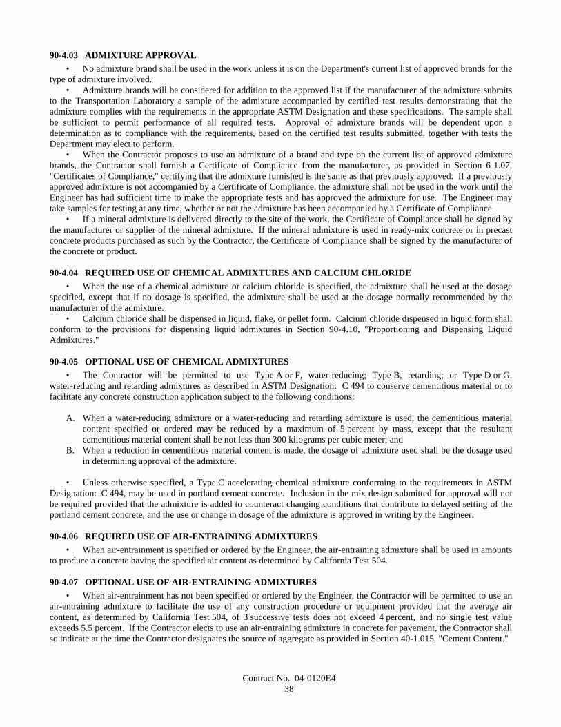
Contract No. 04-0120E438
90-4.03 ADMIXTURE APPROVAL• No admixture brand shall be used in the work unless it is on the Department's current list of approved brands for the
type of admixture involved.• Admixture brands will be considered for addition to the approved list if the manufacturer of the admixture submits
to the Transportation Laboratory a sample of the admixture accompanied by certified test results demonstrating that theadmixture complies with the requirements in the appropriate ASTM Designation and these specifications. The sample shallbe sufficient to permit performance of all required tests. Approval of admixture brands will be dependent upon adetermination as to compliance with the requirements, based on the certified test results submitted, together with tests theDepartment may elect to perform.
• When the Contractor proposes to use an admixture of a brand and type on the current list of approved admixturebrands, the Contractor shall furnish a Certificate of Compliance from the manufacturer, as provided in Section 6-1.07,"Certificates of Compliance," certifying that the admixture furnished is the same as that previously approved. If a previouslyapproved admixture is not accompanied by a Certificate of Compliance, the admixture shall not be used in the work until theEngineer has had sufficient time to make the appropriate tests and has approved the admixture for use. The Engineer maytake samples for testing at any time, whether or not the admixture has been accompanied by a Certificate of Compliance.
• If a mineral admixture is delivered directly to the site of the work, the Certificate of Compliance shall be signed bythe manufacturer or supplier of the mineral admixture. If the mineral admixture is used in ready-mix concrete or in precastconcrete products purchased as such by the Contractor, the Certificate of Compliance shall be signed by the manufacturer ofthe concrete or product.
90-4.04 REQUIRED USE OF CHEMICAL ADMIXTURES AND CALCIUM CHLORIDE• When the use of a chemical admixture or calcium chloride is specified, the admixture shall be used at the dosage
specified, except that if no dosage is specified, the admixture shall be used at the dosage normally recommended by themanufacturer of the admixture.
• Calcium chloride shall be dispensed in liquid, flake, or pellet form. Calcium chloride dispensed in liquid form shallconform to the provisions for dispensing liquid admixtures in Section 90-4.10, "Proportioning and Dispensing LiquidAdmixtures."
90-4.05 OPTIONAL USE OF CHEMICAL ADMIXTURES• The Contractor will be permitted to use Type A or F, water-reducing; Type B, retarding; or Type D or G,
water-reducing and retarding admixtures as described in ASTM Designation: C 494 to conserve cementitious material or tofacilitate any concrete construction application subject to the following conditions:
A. When a water-reducing admixture or a water-reducing and retarding admixture is used, the cementitious materialcontent specified or ordered may be reduced by a maximum of 5 percent by mass, except that the resultantcementitious material content shall be not less than 300 kilograms per cubic meter; and
B. When a reduction in cementitious material content is made, the dosage of admixture used shall be the dosage usedin determining approval of the admixture.
• Unless otherwise specified, a Type C accelerating chemical admixture conforming to the requirements in ASTMDesignation: C 494, may be used in portland cement concrete. Inclusion in the mix design submitted for approval will notbe required provided that the admixture is added to counteract changing conditions that contribute to delayed setting of theportland cement concrete, and the use or change in dosage of the admixture is approved in writing by the Engineer.
90-4.06 REQUIRED USE OF AIR-ENTRAINING ADMIXTURES• When air-entrainment is specified or ordered by the Engineer, the air-entraining admixture shall be used in amounts
to produce a concrete having the specified air content as determined by California Test 504.
90-4.07 OPTIONAL USE OF AIR-ENTRAINING ADMIXTURES• When air-entrainment has not been specified or ordered by the Engineer, the Contractor will be permitted to use an
air-entraining admixture to facilitate the use of any construction procedure or equipment provided that the average aircontent, as determined by California Test 504, of 3 successive tests does not exceed 4 percent, and no single test valueexceeds 5.5 percent. If the Contractor elects to use an air-entraining admixture in concrete for pavement, the Contractor shallso indicate at the time the Contractor designates the source of aggregate as provided in Section 40-1.015, "Cement Content."
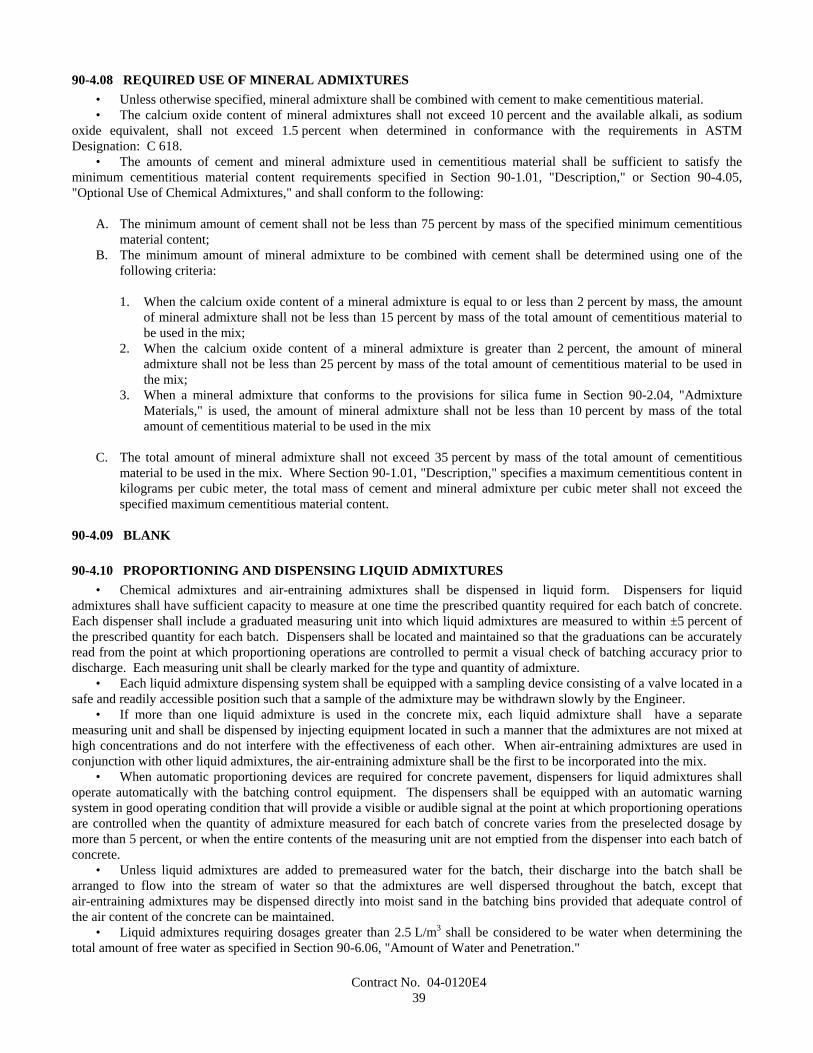
Contract No. 04-0120E439
90-4.08 REQUIRED USE OF MINERAL ADMIXTURES• Unless otherwise specified, mineral admixture shall be combined with cement to make cementitious material.• The calcium oxide content of mineral admixtures shall not exceed 10 percent and the available alkali, as sodium
oxide equivalent, shall not exceed 1.5 percent when determined in conformance with the requirements in ASTMDesignation: C 618.
• The amounts of cement and mineral admixture used in cementitious material shall be sufficient to satisfy theminimum cementitious material content requirements specified in Section 90-1.01, "Description," or Section 90-4.05,"Optional Use of Chemical Admixtures," and shall conform to the following:
A. The minimum amount of cement shall not be less than 75 percent by mass of the specified minimum cementitiousmaterial content;
B. The minimum amount of mineral admixture to be combined with cement shall be determined using one of thefollowing criteria:
1. When the calcium oxide content of a mineral admixture is equal to or less than 2 percent by mass, the amountof mineral admixture shall not be less than 15 percent by mass of the total amount of cementitious material tobe used in the mix;
2. When the calcium oxide content of a mineral admixture is greater than 2 percent, the amount of mineraladmixture shall not be less than 25 percent by mass of the total amount of cementitious material to be used inthe mix;
3. When a mineral admixture that conforms to the provisions for silica fume in Section 90-2.04, "AdmixtureMaterials," is used, the amount of mineral admixture shall not be less than 10 percent by mass of the totalamount of cementitious material to be used in the mix
C. The total amount of mineral admixture shall not exceed 35 percent by mass of the total amount of cementitiousmaterial to be used in the mix. Where Section 90-1.01, "Description," specifies a maximum cementitious content inkilograms per cubic meter, the total mass of cement and mineral admixture per cubic meter shall not exceed thespecified maximum cementitious material content.
90-4.09 BLANK
90-4.10 PROPORTIONING AND DISPENSING LIQUID ADMIXTURES• Chemical admixtures and air-entraining admixtures shall be dispensed in liquid form. Dispensers for liquid
admixtures shall have sufficient capacity to measure at one time the prescribed quantity required for each batch of concrete.Each dispenser shall include a graduated measuring unit into which liquid admixtures are measured to within ±5 percent ofthe prescribed quantity for each batch. Dispensers shall be located and maintained so that the graduations can be accuratelyread from the point at which proportioning operations are controlled to permit a visual check of batching accuracy prior todischarge. Each measuring unit shall be clearly marked for the type and quantity of admixture.
• Each liquid admixture dispensing system shall be equipped with a sampling device consisting of a valve located in asafe and readily accessible position such that a sample of the admixture may be withdrawn slowly by the Engineer.
• If more than one liquid admixture is used in the concrete mix, each liquid admixture shall have a separatemeasuring unit and shall be dispensed by injecting equipment located in such a manner that the admixtures are not mixed athigh concentrations and do not interfere with the effectiveness of each other. When air-entraining admixtures are used inconjunction with other liquid admixtures, the air-entraining admixture shall be the first to be incorporated into the mix.
• When automatic proportioning devices are required for concrete pavement, dispensers for liquid admixtures shalloperate automatically with the batching control equipment. The dispensers shall be equipped with an automatic warningsystem in good operating condition that will provide a visible or audible signal at the point at which proportioning operationsare controlled when the quantity of admixture measured for each batch of concrete varies from the preselected dosage bymore than 5 percent, or when the entire contents of the measuring unit are not emptied from the dispenser into each batch ofconcrete.
• Unless liquid admixtures are added to premeasured water for the batch, their discharge into the batch shall bearranged to flow into the stream of water so that the admixtures are well dispersed throughout the batch, except thatair-entraining admixtures may be dispensed directly into moist sand in the batching bins provided that adequate control ofthe air content of the concrete can be maintained.
• Liquid admixtures requiring dosages greater than 2.5 L/m3 shall be considered to be water when determining thetotal amount of free water as specified in Section 90-6.06, "Amount of Water and Penetration."

Contract No. 04-0120E440
• Special admixtures, such as "high range" water reducers that may contribute to a high rate of slump loss, shall bemeasured and dispensed as recommended by the admixture manufacturer and as approved by the Engineer.
90-4.11 STORAGE, PROPORTIONING, AND DISPENSING OF MINERAL ADMIXTURES• Mineral admixtures shall be protected from exposure to moisture until used. Sacked material shall be piled to
permit access for tally, inspection and identification for each shipment.• Adequate facilities shall be provided to assure that mineral admixtures meeting the specified requirements are kept
separate from other mineral admixtures in order to prevent any but the specified mineral admixtures from entering the work.Safe and suitable facilities for sampling mineral admixtures shall be provided at the weigh hopper or in the feed lineimmediately in advance of the hopper.
• Mineral admixtures shall be incorporated into concrete using equipment conforming to the requirements for cementweigh hoppers, and charging and discharging mechanisms in ASTM Designation: C 94, in Section 90-5.03, "Proportioning,"and in this Section 90-4.11.
• When concrete is completely mixed in stationary paving mixers, the mineral admixture shall be weighed in aseparate weigh hopper conforming to the provisions for cement weigh hoppers and charging and discharging mechanisms inSection 90-5.03A, "Proportioning for Pavement," and the mineral admixture and cement shall be introduced simultaneouslyinto the mixer proportionately with the aggregate. If the mineral admixture is not weighed in a separate weigh hopper, theContractor shall provide certification that the stationary mixer is capable of mixing the cement, admixture, aggregates andwater uniformly prior to discharge. Certification shall contain the following:
A. Test results for 2 compressive strength test cylinders of concrete taken within the first one-third and 2 compressivestrength test cylinders of concrete taken within the last one-third of the concrete discharged from a single batch fromthe stationary paving mixer. Strength tests and cylinder preparation will be in conformance with the provisions ofSection 90-9, "Compressive Strength;"
B. Calculations demonstrating that the difference in the averages of 2 compressive strengths taken in the first one-thirdis no greater than 7.5 percent different than the averages of 2 compressive strengths taken in the last one-third of theconcrete discharged from a single batch from the stationary paving mixer. Strength tests and cylinder preparationwill be in conformance with the provisions of Section 90-9, "Compressive Strength;" and
C. The mixer rotation speed and time of mixing prior to discharge that are required to produce a mix that meets therequirements above.
90-5 PROPORTIONING
90-5.01 STORAGE OF AGGREGATES• Aggregates shall be stored or stockpiled in such a manner that separation of coarse and fine particles of each size
shall be avoided and also that the various sizes shall not become intermixed before proportioning.• Aggregates shall be stored or stockpiled and handled in a manner that shall prevent contamination by foreign
materials. In addition, storage of aggregates at batching or mixing facilities that are erected subsequent to the award of thecontract and that furnish concrete to the project shall conform to the following:
A. Intermingling of the different sizes of aggregates shall be positively prevented. The Contractor shall take thenecessary measures to prevent intermingling. The preventive measures may include, but are not necessarily limitedto, physical separation of stockpiles or construction of bulkheads of adequate length and height; and
B. Contamination of aggregates by contact with the ground shall be positively prevented. The Contractor shall take thenecessary measures to prevent contamination. The preventive measures shall include, but are not necessarilylimited to, placing aggregates on wooden platforms or on hardened surfaces consisting of portland cement concrete,asphalt concrete, or cement treated material.
• In placing aggregates in storage or in moving the aggregates from storage to the weigh hopper of the batching plant,any method that may cause segregation, degradation, or the combining of materials of different gradings that will result inany size of aggregate at the weigh hopper failing to meet the grading requirements, shall be discontinued. Any method ofhandling aggregates that results in excessive breakage of particles shall be discontinued. The use of suitable devices toreduce impact of falling aggregates may be required by the Engineer.
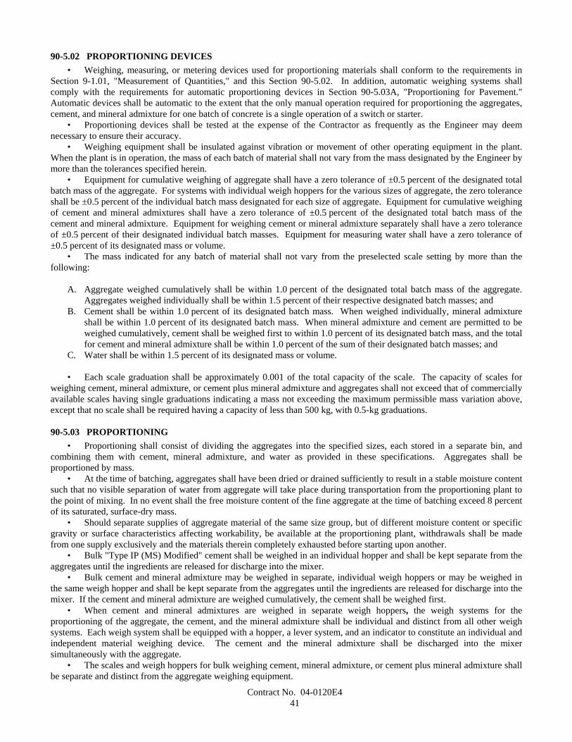
Contract No. 04-0120E441
90-5.02 PROPORTIONING DEVICES• Weighing, measuring, or metering devices used for proportioning materials shall conform to the requirements in
Section 9-1.01, "Measurement of Quantities," and this Section 90-5.02. In addition, automatic weighing systems shallcomply with the requirements for automatic proportioning devices in Section 90-5.03A, "Proportioning for Pavement."Automatic devices shall be automatic to the extent that the only manual operation required for proportioning the aggregates,cement, and mineral admixture for one batch of concrete is a single operation of a switch or starter.
• Proportioning devices shall be tested at the expense of the Contractor as frequently as the Engineer may deemnecessary to ensure their accuracy.
• Weighing equipment shall be insulated against vibration or movement of other operating equipment in the plant.When the plant is in operation, the mass of each batch of material shall not vary from the mass designated by the Engineer bymore than the tolerances specified herein.
• Equipment for cumulative weighing of aggregate shall have a zero tolerance of ±0.5 percent of the designated totalbatch mass of the aggregate. For systems with individual weigh hoppers for the various sizes of aggregate, the zero toleranceshall be ±0.5 percent of the individual batch mass designated for each size of aggregate. Equipment for cumulative weighingof cement and mineral admixtures shall have a zero tolerance of ±0.5 percent of the designated total batch mass of thecement and mineral admixture. Equipment for weighing cement or mineral admixture separately shall have a zero toleranceof ±0.5 percent of their designated individual batch masses. Equipment for measuring water shall have a zero tolerance of±0.5 percent of its designated mass or volume.
• The mass indicated for any batch of material shall not vary from the preselected scale setting by more than thefollowing:
A. Aggregate weighed cumulatively shall be within 1.0 percent of the designated total batch mass of the aggregate.Aggregates weighed individually shall be within 1.5 percent of their respective designated batch masses; and
B. Cement shall be within 1.0 percent of its designated batch mass. When weighed individually, mineral admixtureshall be within 1.0 percent of its designated batch mass. When mineral admixture and cement are permitted to beweighed cumulatively, cement shall be weighed first to within 1.0 percent of its designated batch mass, and the totalfor cement and mineral admixture shall be within 1.0 percent of the sum of their designated batch masses; and
C. Water shall be within 1.5 percent of its designated mass or volume.
• Each scale graduation shall be approximately 0.001 of the total capacity of the scale. The capacity of scales forweighing cement, mineral admixture, or cement plus mineral admixture and aggregates shall not exceed that of commerciallyavailable scales having single graduations indicating a mass not exceeding the maximum permissible mass variation above,except that no scale shall be required having a capacity of less than 500 kg, with 0.5-kg graduations.
90-5.03 PROPORTIONING• Proportioning shall consist of dividing the aggregates into the specified sizes, each stored in a separate bin, and
combining them with cement, mineral admixture, and water as provided in these specifications. Aggregates shall beproportioned by mass.
• At the time of batching, aggregates shall have been dried or drained sufficiently to result in a stable moisture contentsuch that no visible separation of water from aggregate will take place during transportation from the proportioning plant tothe point of mixing. In no event shall the free moisture content of the fine aggregate at the time of batching exceed 8 percentof its saturated, surface-dry mass.
• Should separate supplies of aggregate material of the same size group, but of different moisture content or specificgravity or surface characteristics affecting workability, be available at the proportioning plant, withdrawals shall be madefrom one supply exclusively and the materials therein completely exhausted before starting upon another.
• Bulk "Type IP (MS) Modified" cement shall be weighed in an individual hopper and shall be kept separate from theaggregates until the ingredients are released for discharge into the mixer.
• Bulk cement and mineral admixture may be weighed in separate, individual weigh hoppers or may be weighed inthe same weigh hopper and shall be kept separate from the aggregates until the ingredients are released for discharge into themixer. If the cement and mineral admixture are weighed cumulatively, the cement shall be weighed first.
• When cement and mineral admixtures are weighed in separate weigh hoppers, the weigh systems for theproportioning of the aggregate, the cement, and the mineral admixture shall be individual and distinct from all other weighsystems. Each weigh system shall be equipped with a hopper, a lever system, and an indicator to constitute an individual andindependent material weighing device. The cement and the mineral admixture shall be discharged into the mixersimultaneously with the aggregate.
• The scales and weigh hoppers for bulk weighing cement, mineral admixture, or cement plus mineral admixture shallbe separate and distinct from the aggregate weighing equipment.
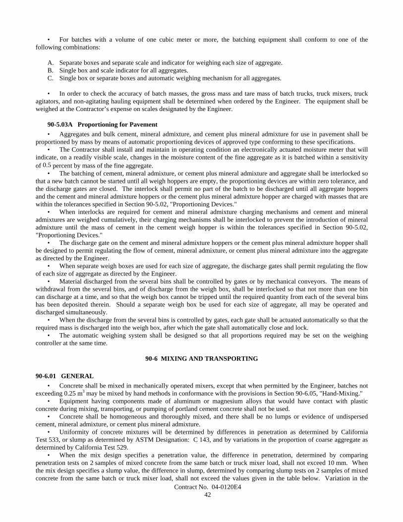
Contract No. 04-0120E442
• For batches with a volume of one cubic meter or more, the batching equipment shall conform to one of thefollowing combinations:
A. Separate boxes and separate scale and indicator for weighing each size of aggregate.B. Single box and scale indicator for all aggregates.C. Single box or separate boxes and automatic weighing mechanism for all aggregates.
• In order to check the accuracy of batch masses, the gross mass and tare mass of batch trucks, truck mixers, truckagitators, and non-agitating hauling equipment shall be determined when ordered by the Engineer. The equipment shall beweighed at the Contractor’s expense on scales designated by the Engineer.
90-5.03A Proportioning for Pavement• Aggregates and bulk cement, mineral admixture, and cement plus mineral admixture for use in pavement shall be
proportioned by mass by means of automatic proportioning devices of approved type conforming to these specifications.• The Contractor shall install and maintain in operating condition an electronically actuated moisture meter that will
indicate, on a readily visible scale, changes in the moisture content of the fine aggregate as it is batched within a sensitivityof 0.5 percent by mass of the fine aggregate.
• The batching of cement, mineral admixture, or cement plus mineral admixture and aggregate shall be interlocked sothat a new batch cannot be started until all weigh hoppers are empty, the proportioning devices are within zero tolerance, andthe discharge gates are closed. The interlock shall permit no part of the batch to be discharged until all aggregate hoppersand the cement and mineral admixture hoppers or the cement plus mineral admixture hopper are charged with masses that arewithin the tolerances specified in Section 90-5.02, "Proportioning Devices."
• When interlocks are required for cement and mineral admixture charging mechanisms and cement and mineraladmixtures are weighed cumulatively, their charging mechanisms shall be interlocked to prevent the introduction of mineraladmixture until the mass of cement in the cement weigh hopper is within the tolerances specified in Section 90-5.02,"Proportioning Devices."
• The discharge gate on the cement and mineral admixture hoppers or the cement plus mineral admixture hopper shallbe designed to permit regulating the flow of cement, mineral admixture, or cement plus mineral admixture into the aggregateas directed by the Engineer.
• When separate weigh boxes are used for each size of aggregate, the discharge gates shall permit regulating the flowof each size of aggregate as directed by the Engineer.
• Material discharged from the several bins shall be controlled by gates or by mechanical conveyors. The means ofwithdrawal from the several bins, and of discharge from the weigh box, shall be interlocked so that not more than one bincan discharge at a time, and so that the weigh box cannot be tripped until the required quantity from each of the several binshas been deposited therein. Should a separate weigh box be used for each size of aggregate, all may be operated anddischarged simultaneously.
• When the discharge from the several bins is controlled by gates, each gate shall be actuated automatically so that therequired mass is discharged into the weigh box, after which the gate shall automatically close and lock.
• The automatic weighing system shall be designed so that all proportions required may be set on the weighingcontroller at the same time.
90-6 MIXING AND TRANSPORTING
90-6.01 GENERAL• Concrete shall be mixed in mechanically operated mixers, except that when permitted by the Engineer, batches not
exceeding 0.25 m3 may be mixed by hand methods in conformance with the provisions in Section 90-6.05, "Hand-Mixing."• Equipment having components made of aluminum or magnesium alloys that would have contact with plastic
concrete during mixing, transporting, or pumping of portland cement concrete shall not be used.• Concrete shall be homogeneous and thoroughly mixed, and there shall be no lumps or evidence of undispersed
cement, mineral admixture, or cement plus mineral admixture.• Uniformity of concrete mixtures will be determined by differences in penetration as determined by California
Test 533, or slump as determined by ASTM Designation: C 143, and by variations in the proportion of coarse aggregate asdetermined by California Test 529.
• When the mix design specifies a penetration value, the difference in penetration, determined by comparingpenetration tests on 2 samples of mixed concrete from the same batch or truck mixer load, shall not exceed 10 mm. Whenthe mix design specifies a slump value, the difference in slump, determined by comparing slump tests on 2 samples of mixedconcrete from the same batch or truck mixer load, shall not exceed the values given in the table below. Variation in the
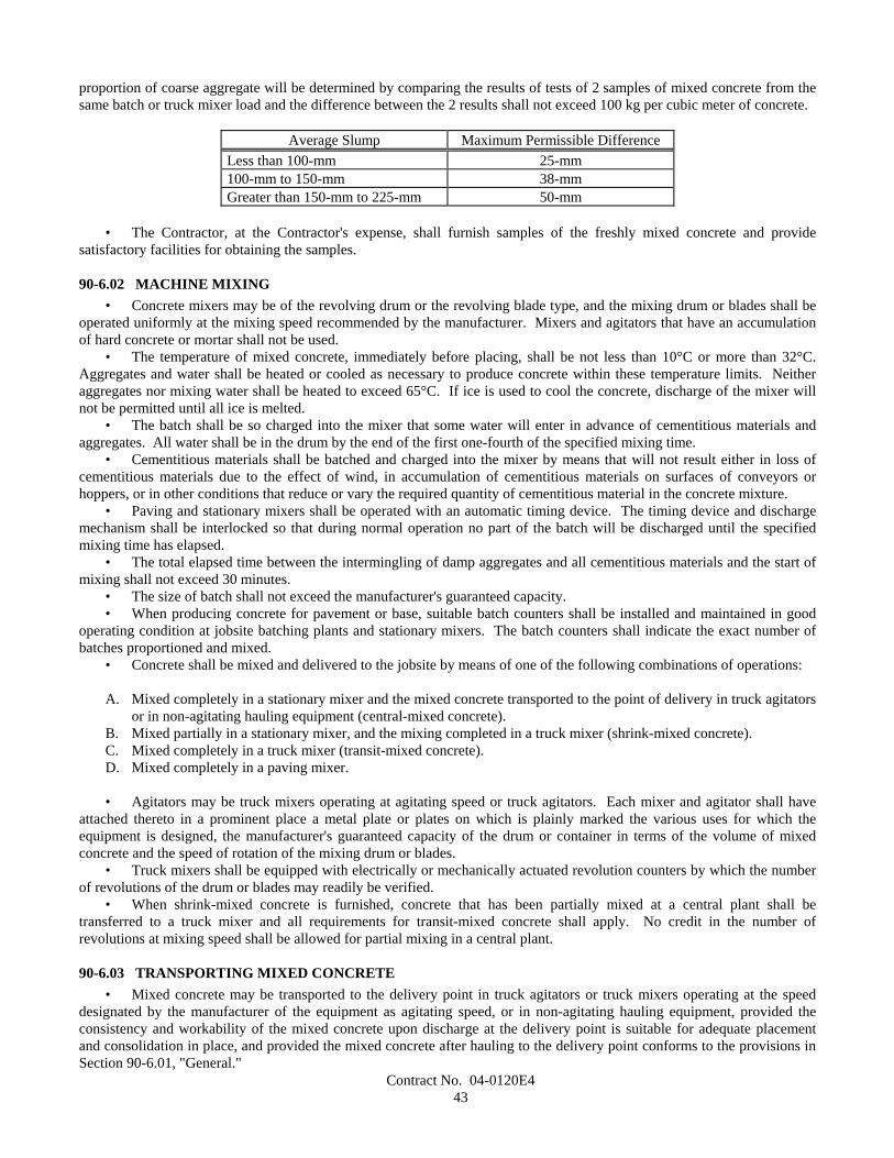
Contract No. 04-0120E443
proportion of coarse aggregate will be determined by comparing the results of tests of 2 samples of mixed concrete from thesame batch or truck mixer load and the difference between the 2 results shall not exceed 100 kg per cubic meter of concrete.
Average Slump Maximum Permissible DifferenceLess than 100-mm 25-mm100-mm to 150-mm 38-mmGreater than 150-mm to 225-mm 50-mm
• The Contractor, at the Contractor's expense, shall furnish samples of the freshly mixed concrete and providesatisfactory facilities for obtaining the samples.
90-6.02 MACHINE MIXING• Concrete mixers may be of the revolving drum or the revolving blade type, and the mixing drum or blades shall be
operated uniformly at the mixing speed recommended by the manufacturer. Mixers and agitators that have an accumulationof hard concrete or mortar shall not be used.
• The temperature of mixed concrete, immediately before placing, shall be not less than 10°C or more than 32°C.Aggregates and water shall be heated or cooled as necessary to produce concrete within these temperature limits. Neitheraggregates nor mixing water shall be heated to exceed 65°C. If ice is used to cool the concrete, discharge of the mixer willnot be permitted until all ice is melted.
• The batch shall be so charged into the mixer that some water will enter in advance of cementitious materials andaggregates. All water shall be in the drum by the end of the first one-fourth of the specified mixing time.
• Cementitious materials shall be batched and charged into the mixer by means that will not result either in loss ofcementitious materials due to the effect of wind, in accumulation of cementitious materials on surfaces of conveyors orhoppers, or in other conditions that reduce or vary the required quantity of cementitious material in the concrete mixture.
• Paving and stationary mixers shall be operated with an automatic timing device. The timing device and dischargemechanism shall be interlocked so that during normal operation no part of the batch will be discharged until the specifiedmixing time has elapsed.
• The total elapsed time between the intermingling of damp aggregates and all cementitious materials and the start ofmixing shall not exceed 30 minutes.
• The size of batch shall not exceed the manufacturer's guaranteed capacity.• When producing concrete for pavement or base, suitable batch counters shall be installed and maintained in good
operating condition at jobsite batching plants and stationary mixers. The batch counters shall indicate the exact number ofbatches proportioned and mixed.
• Concrete shall be mixed and delivered to the jobsite by means of one of the following combinations of operations:
A. Mixed completely in a stationary mixer and the mixed concrete transported to the point of delivery in truck agitatorsor in non-agitating hauling equipment (central-mixed concrete).
B. Mixed partially in a stationary mixer, and the mixing completed in a truck mixer (shrink-mixed concrete).C. Mixed completely in a truck mixer (transit-mixed concrete).D. Mixed completely in a paving mixer.
• Agitators may be truck mixers operating at agitating speed or truck agitators. Each mixer and agitator shall haveattached thereto in a prominent place a metal plate or plates on which is plainly marked the various uses for which theequipment is designed, the manufacturer's guaranteed capacity of the drum or container in terms of the volume of mixedconcrete and the speed of rotation of the mixing drum or blades.
• Truck mixers shall be equipped with electrically or mechanically actuated revolution counters by which the numberof revolutions of the drum or blades may readily be verified.
• When shrink-mixed concrete is furnished, concrete that has been partially mixed at a central plant shall betransferred to a truck mixer and all requirements for transit-mixed concrete shall apply. No credit in the number ofrevolutions at mixing speed shall be allowed for partial mixing in a central plant.
90-6.03 TRANSPORTING MIXED CONCRETE• Mixed concrete may be transported to the delivery point in truck agitators or truck mixers operating at the speed
designated by the manufacturer of the equipment as agitating speed, or in non-agitating hauling equipment, provided theconsistency and workability of the mixed concrete upon discharge at the delivery point is suitable for adequate placementand consolidation in place, and provided the mixed concrete after hauling to the delivery point conforms to the provisions inSection 90-6.01, "General."
Contract No. 04-0120E444
• Truck agitators shall be loaded not to exceed the manufacturer's guaranteed capacity and shall maintain the mixedconcrete in a thoroughly mixed and uniform mass during hauling.
• Bodies of non-agitating hauling equipment shall be constructed so that leakage of the concrete mix, or any partthereof, will not occur at any time.
• Concrete hauled in open-top vehicles shall be protected during hauling against rain or against exposure to the sunfor more than 20 minutes when the ambient temperature exceeds 24°C.
• No additional mixing water shall be incorporated into the concrete during hauling or after arrival at the deliverypoint, unless authorized by the Engineer. If the Engineer authorizes additional water to be incorporated into the concrete, thedrum shall be revolved not less than 30 revolutions at mixing speed after the water is added and before discharge iscommenced.
• The rate of discharge of mixed concrete from truck mixer-agitators shall be controlled by the speed of rotation ofthe drum in the discharge direction with the discharge gate fully open.
• When a truck mixer or agitator is used for transporting concrete to the delivery point, discharge shall be completedwithin 1.5 hours or before 250 revolutions of the drum or blades, whichever occurs first, after the introduction of the cementto the aggregates. Under conditions contributing to quick stiffening of the concrete, or when the temperature of the concreteis 30°C or above, the time allowed may be less than 1.5 hours.
• When non-agitating hauling equipment is used for transporting concrete to the delivery point, discharge shall becompleted within one hour after the addition of the cement to the aggregates. Under conditions contributing to quickstiffening of the concrete, or when the temperature of the concrete is 30°C or above, the time between the introduction ofcement to the aggregates and discharge shall not exceed 45 minutes.
• Each load of concrete delivered at the jobsite shall be accompanied by a weighmaster certificate showing the mixidentification number, non-repeating load number, date and time at which the materials were batched, the total amount ofwater added to the load, and for transit-mixed concrete, the reading of the revolution counter at the time the truck mixer ischarged with cement. This weighmaster certificate shall also show the actual scale masses (kilograms) for the ingredientsbatched. Theoretical or target batch masses shall not be used as a substitute for actual scale masses.
• Weighmaster certificates shall be provided in printed form, or if approved by the Engineer, the data may besubmitted in electronic media. Electronic media shall be presented in a tab-delimited format on a 90 mm diskette with acapacity of at least 1.4 megabytes. Captured data, for the ingredients represented by each batch shall be "line feed, carriagereturn" (LFCR) and "one line, separate record" with allowances for sufficient fields to satisfy the amount of data required bythese specifications.
• The Contractor may furnish a weighmaster certificate accompanied by a separate certificate that lists the actualbatch masses or measurements for a load of concrete provided that both certificates are imprinted with the samenon-repeating load number that is unique to the contract and delivered to the jobsite with the load.
• Weighmaster certificates furnished by the Contractor shall conform to the provisions in Section 9-1.01,"Measurement of Quantities."
90-6.04 TIME OR AMOUNT OF MIXING• Mixing of concrete in paving or stationary mixers shall continue for the required mixing time after all ingredients,
except water and admixture, if added with the water, are in the mixing compartment of the mixer before any part of the batchis released. Transfer time in multiple drum mixers shall not be counted as part of the required mixing time.
• The required mixing time, in paving or stationary mixers, of concrete used for concrete structures, except minorstructures, shall be not less than 90 seconds or more than 5 minutes, except that when directed by the Engineer in writing, therequirements of the following paragraph shall apply.
• The required mixing time, in paving or stationary mixers, except as provided in the preceding paragraph, shall benot less than 50 seconds or more than 5 minutes.
• The minimum required revolutions at the mixing speed for transit-mixed concrete shall not be less than thatrecommended by the mixer manufacturer, but in no case shall the number of revolutions be less than that required toconsistently produce concrete conforming to the provisions for uniformity in Section 90-6.01, "General."
90-6.05 HAND-MIXING• Hand-mixed concrete shall be made in batches of not more than 0.25 m3 and shall be mixed on a watertight, level
platform. The proper amount of coarse aggregate shall be measured in measuring boxes and spread on the platform and thefine aggregate shall be spread on this layer, the 2 layers being not more than 0.3 meters in total depth. On this mixture shallbe spread the dry cement and mineral admixture and the whole mass turned no fewer than 2 times dry; then sufficient cleanwater shall be added, evenly distributed, and the whole mass again turned no fewer than 3 times, not including placing in thecarriers or forms.
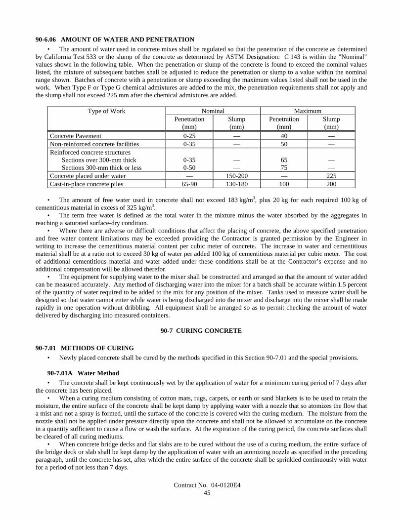
Contract No. 04-0120E445
90-6.06 AMOUNT OF WATER AND PENETRATION• The amount of water used in concrete mixes shall be regulated so that the penetration of the concrete as determined
by California Test 533 or the slump of the concrete as determined by ASTM Designation: C 143 is within the "Nominal"values shown in the following table. When the penetration or slump of the concrete is found to exceed the nominal valueslisted, the mixture of subsequent batches shall be adjusted to reduce the penetration or slump to a value within the nominalrange shown. Batches of concrete with a penetration or slump exceeding the maximum values listed shall not be used in thework. When Type F or Type G chemical admixtures are added to the mix, the penetration requirements shall not apply andthe slump shall not exceed 225 mm after the chemical admixtures are added.
Type of Work Nominal MaximumPenetration Slump Penetration Slump
(mm) (mm) (mm) (mm)Concrete Pavement 0-25 — 40 —Non-reinforced concrete facilities 0-35 — 50 —Reinforced concrete structures
Sections over 300-mm thick 0-35 — 65 —Sections 300-mm thick or less 0-50 — 75 —
Concrete placed under water — 150-200 — 225Cast-in-place concrete piles 65-90 130-180 100 200
• The amount of free water used in concrete shall not exceed 183 kg/m3, plus 20 kg for each required 100 kg ofcementitious material in excess of 325 kg/m3.
• The term free water is defined as the total water in the mixture minus the water absorbed by the aggregates inreaching a saturated surface-dry condition.
• Where there are adverse or difficult conditions that affect the placing of concrete, the above specified penetrationand free water content limitations may be exceeded providing the Contractor is granted permission by the Engineer inwriting to increase the cementitious material content per cubic meter of concrete. The increase in water and cementitiousmaterial shall be at a ratio not to exceed 30 kg of water per added 100 kg of cementitious material per cubic meter. The costof additional cementitious material and water added under these conditions shall be at the Contractor’s expense and noadditional compensation will be allowed therefor.
• The equipment for supplying water to the mixer shall be constructed and arranged so that the amount of water addedcan be measured accurately. Any method of discharging water into the mixer for a batch shall be accurate within 1.5 percentof the quantity of water required to be added to the mix for any position of the mixer. Tanks used to measure water shall bedesigned so that water cannot enter while water is being discharged into the mixer and discharge into the mixer shall be maderapidly in one operation without dribbling. All equipment shall be arranged so as to permit checking the amount of waterdelivered by discharging into measured containers.
90-7 CURING CONCRETE
90-7.01 METHODS OF CURING• Newly placed concrete shall be cured by the methods specified in this Section 90-7.01 and the special provisions.
90-7.01A Water Method• The concrete shall be kept continuously wet by the application of water for a minimum curing period of 7 days after
the concrete has been placed.• When a curing medium consisting of cotton mats, rugs, carpets, or earth or sand blankets is to be used to retain the
moisture, the entire surface of the concrete shall be kept damp by applying water with a nozzle that so atomizes the flow thata mist and not a spray is formed, until the surface of the concrete is covered with the curing medium. The moisture from thenozzle shall not be applied under pressure directly upon the concrete and shall not be allowed to accumulate on the concretein a quantity sufficient to cause a flow or wash the surface. At the expiration of the curing period, the concrete surfaces shallbe cleared of all curing mediums.
• When concrete bridge decks and flat slabs are to be cured without the use of a curing medium, the entire surface ofthe bridge deck or slab shall be kept damp by the application of water with an atomizing nozzle as specified in the precedingparagraph, until the concrete has set, after which the entire surface of the concrete shall be sprinkled continuously with waterfor a period of not less than 7 days.
Contract No. 04-0120E446
90-7.01B Curing Compound Method• Surfaces of the concrete that are exposed to the air shall be sprayed uniformly with a curing compound.• Curing compounds to be used shall be as follows:
1. Pigmented curing compound conforming to the requirements in ASTM Designation: C 309, Type 2, Class B,except the resin type shall be poly-alpha-methylstyrene.
2. Pigmented curing compound conforming to the requirements in ASTM Designation: C 309, Type 2, Class B.3. Pigmented curing compound conforming to the requirements in ASTM Designation: C 309, Type 2, Class A.4. Non-pigmented curing compound conforming to the requirements in ASTM Designation: C 309, Type 1, Class B.5. Non-pigmented curing compound conforming to the requirements in ASTM Designation: C 309, Type 1, Class A.6. Non-pigmented curing compound with fugitive dye conforming to the requirements in ASTM Designation: C 309,
Type 1-D, Class A.
• The infrared scan for the dried vehicle from curing compound (1) shall match the infrared scan on file at theTransportation Laboratory.
• The loss of water for each type of curing compound, when tested in conformance with the requirements inCalifornia Test 534, shall not be more than 0.15-kg/m2 in 24 hours.
• The curing compound to be used will be specified elsewhere in these specifications or in the special provisions.• When the use of curing compound is required or permitted elsewhere in these specifications or in the special
provisions and no specific kind is specified, any of the curing compounds listed above may be used.• Curing compound shall be applied at a nominal rate of 3.7 m2/L, unless otherwise specified.• At any point, the application rate shall be within ±1.2 m2/L of the nominal rate specified, and the average
application rate shall be within ±0.5 m2/L of the nominal rate specified when tested in conformance with the requirements inCalifornia Test 535. Runs, sags, thin areas, skips, or holidays in the applied curing compound shall be evidence that theapplication is not satisfactory.
• Curing compounds shall be applied using power operated spray equipment. The power operated sprayingequipment shall be equipped with an operational pressure gage and a means of controlling the pressure. Hand spraying ofsmall and irregular areas that are not reasonably accessible to mechanical spraying equipment, in the opinion of the Engineer,may be permitted.
• The curing compound shall be applied to the concrete following the surface finishing operation, immediately beforethe moisture sheen disappears from the surface, but before any drying shrinkage or craze cracks begin to appear. In the eventof any drying or cracking of the surface, application of water with an atomizing nozzle as specified in Section 90-7.01A,"Water Method," shall be started immediately and shall be continued until application of the compound is resumed or started;however, the compound shall not be applied over any resulting freestanding water. Should the film of compound bedamaged from any cause before the expiration of 7 days after the concrete is placed in the case of structures and 72 hours inthe case of pavement, the damaged portion shall be repaired immediately with additional compound.
• At the time of use, compounds containing pigments shall be in a thoroughly mixed condition with the pigmentuniformly dispersed throughout the vehicle. A paddle shall be used to loosen all settled pigment from the bottom of thecontainer, and a power driven agitator shall be used to disperse the pigment uniformly throughout the vehicle.
• Agitation shall not introduce air or other foreign substance into the curing compound.• The manufacturer shall include in the curing compound the necessary additives for control of sagging, pigment
settling, leveling, de-emulsification, or other requisite qualities of a satisfactory working material. Pigmented curingcompounds shall be manufactured so that the pigment does not settle badly, does not cake or thicken in the container, anddoes not become granular or curdled. Settlement of pigment shall be a thoroughly wetted, soft, mushy mass permitting thecomplete and easy vertical penetration of a paddle. Settled pigment shall be easily redispersed, with minimum resistance tothe sideways manual motion of the paddle across the bottom of the container, to form a smooth uniform product of theproper consistency.
• Curing compounds shall remain sprayable at temperatures above 4°C and shall not be diluted or altered aftermanufacture.
• The curing compound shall be packaged in clean 1040-L totes, 210-L barrelsor 19-L pails shall be supplied from a suitable storage tank located at the jobsite. The containers shall comply with
"Title 49, Code of Federal Regulations, Hazardous Materials Regulations." The 1040-L totes and the 210-L barrels shallhave removable lids and airtight fasteners. The 19-L pails shall be round and have standard full open head and bail. Lidswith bungholes shall not be permitted. Settling or separation of solids in containers, except tanks, must be completelyredispersed with low speed mixing prior to use, in conformance with these specifications and the manufacturer'srecommendations. Mixing shall be accomplished either manually by use of a paddle or by use of a mixing blade driven by adrill motor, at low speed. Mixing blades shall be the type used for mixing paint. On site storage tanks shall be kept clean
Contract No. 04-0120E447
and free of contaminants. Each tank shall have a permanent system designed to completely redisperse settled materialwithout introducing air or other foreign substances.
• Steel containers and lids shall be lined with a coating that will prevent destructive action by the compound orchemical agents in the air space above the compound. The coating shall not come off the container or lid as skins.Containers shall be filled in a manner that will prevent skinning. Plastic containers shall not react with the compound.
• Each container shall be labeled with the manufacturer's name, kind of curing compound, batch number, volume,date of manufacture, and volatile organic compound (VOC) content. The label shall also warn that the curing compoundcontaining pigment shall be well stirred before use. Precautions concerning the handling and the application of curingcompound shall be shown on the label of the curing compound containers in conformance with the Construction SafetyOrders and General Industry Safety Orders of the State of California.
• Containers of curing compound shall be labeled to indicate that the contents fully comply with the rules andregulations concerning air pollution control in the State of California.
• When the curing compound is shipped in tanks or tank trucks, a shipping invoice shall accompany each load. Theinvoice shall contain the same information as that required herein for container labels.
• Curing compound will be sampled by the Engineer at the source of supply or at the jobsite or at both locations.• Curing compound shall be formulated so as to maintain the specified properties for a minimum of one year. The
Engineer may require additional testing before use to determine compliance with these specifications if the compound hasnot been used within one year or whenever the Engineer has reason to believe the compound is no longer satisfactory.
• Tests will be conducted in conformance with the latest ASTM test methods and methods in use by theTransportation Laboratory.
90-7.01C Waterproof Membrane Method• The exposed finished surfaces of concrete shall be sprayed with water, using a nozzle that so atomizes the flow that
a mist and not a spray is formed, until the concrete has set, after which the curing membrane shall be placed. The curingmembrane shall remain in place for a period of not less than 72 hours.
• Sheeting material for curing concrete shall conform to the requirements in AASHTO Designation: M 171 for whitereflective materials.
• The sheeting material shall be fabricated into sheets of such width as to provide a complete cover for the entireconcrete surface. Joints in the sheets shall be securely cemented together in such a manner as to provide a waterproof joint.The joint seams shall have a minimum lap of 100 mm.
• The sheets shall be securely weighted down by placing a bank of earth on the edges of the sheets or by other meanssatisfactory to the Engineer.
• Should any portion of the sheets be broken or damaged before the expiration of 72 hours after being placed, thebroken or damaged portions shall be immediately repaired with new sheets properly cemented into place.
• Sections of membrane that have lost their waterproof qualities or have been damaged to such an extent as to renderthem unfit for curing the concrete shall not be used.
90-7.01D Forms-In-Place Method• Formed surfaces of concrete may be cured by retaining the forms in place. The forms shall remain in place for a
minimum period of 7 days after the concrete has been placed, except that for members over 0.5-m in least dimension theforms shall remain in place for a minimum period of 5 days.
• Joints in the forms and the joints between the end of forms and concrete shall be kept moisture tight during thecuring period. Cracks in the forms and cracks between the forms and the concrete shall be resealed by methods subject to theapproval of the Engineer.
90-7.02 CURING PAVEMENT• The entire exposed area of the pavement, including edges, shall be cured by the waterproof membrane method, or
curing compound method using curing compound (1) or (2) as the Contractor may elect. Should the side forms be removedbefore the expiration of 72 hours following the start of curing, the exposed pavement edges shall also be cured. If thepavement is cured by means of the curing compound method, the sawcut and all portions of the curing compound that havebeen disturbed by sawing operations shall be restored by spraying with additional curing compound.
• Curing shall commence as soon as the finishing process provided in Section 40-1.10, "Final Finishing," has beencompleted. The method selected shall conform to the provisions in Section 90-7.01, "Methods of Curing."
• When the curing compound method is used, the compound shall be applied to the entire pavement surface bymechanical sprayers. Spraying equipment shall be of the fully atomizing type equipped with a tank agitator that provides forcontinual agitation of the curing compound during the time of application. The spray shall be adequately protected againstwind, and the nozzles shall be so oriented or moved mechanically transversely as to result in the minimum specified rate of
Contract No. 04-0120E448
coverage being applied uniformly on exposed faces. Hand spraying of small and irregular areas, and areas inaccessible tomechanical spraying equipment, in the opinion of the Engineer, will be permitted. When the ambient air temperature isabove 15°C, the Contractor shall fog the surface of the concrete with a fine spray of water as specified in Section 90-7.01A,"Water Method." The surface of the pavement shall be kept moist between the hours of 10:00 a.m. and 4:30 p.m. on the daythe concrete is placed. However, the fogging done after the curing compound has been applied shall not begin until thecompound has set sufficiently to prevent displacement. Fogging shall be discontinued if ordered in writing by the Engineer.
90-7.03 CURING STRUCTURES• Newly placed concrete for cast-in-place structures, other than highway bridge decks, shall be cured by the water
method, the forms-in-place method, or, as permitted herein, by the curing compound method, in conformance with theprovisions in Section 90-7.01, "Methods of Curing."
• The curing compound method using a pigmented curing compound may be used on concrete surfaces ofconstruction joints, surfaces that are to be buried underground, and surfaces where only Ordinary Surface Finish is to beapplied and on which a uniform color is not required and that will not be visible from a public traveled way. If theContractor elects to use the curing compound method on the bottom slab of box girder spans, the curing compound shall becuring compound (1).
• The top surface of highway bridge decks shall be cured by both the curing compound method and the water method.The curing compound shall be curing compound (1).
• Concrete surfaces of minor structures, as defined in Section 51-1.02, "Minor Structures," shall be cured by the watermethod, the forms-in-place method or the curing compound method.
• When deemed necessary by the Engineer during periods of hot weather, water shall be applied to concrete surfacesbeing cured by the curing compound method or by the forms-in-place method, until the Engineer determines that a coolingeffect is no longer required. Application of water for this purpose will be paid for as extra work as provided in Section4-1.03D, "Extra Work."
90-7.04 CURING PRECAST CONCRETE MEMBERS• Precast concrete members shall be cured in conformance with any of the methods specified in Section 90-7.01,
"Methods of Curing." Curing shall be provided for the minimum time specified for each method or until the concretereaches its design strength, whichever is less. Steam curing may also be used for precast members and shall conform to thefollowing provisions:
A. After placement of the concrete, members shall be held for a minimum 4-hour presteaming period. If the ambientair temperature is below 10°C, steam shall be applied during the presteaming period to hold the air surrounding themember at a temperature between 10°C and 32°C.
B. To prevent moisture loss on exposed surfaces during the presteaming period, members shall be covered as soon aspossible after casting or the exposed surfaces shall be kept wet by fog spray or wet blankets.
C. Enclosures for steam curing shall allow free circulation of steam about the member and shall be constructed tocontain the live steam with a minimum moisture loss. The use of tarpaulins or similar flexible covers will bepermitted, provided they are kept in good repair and secured in such a manner as to prevent the loss of steam andmoisture.
D. Steam at the jets shall be at low pressure and in a saturated condition. Steam jets shall not impinge directly on theconcrete, test cylinders, or forms. During application of the steam, the temperature rise within the enclosure shallnot exceed 22°C per hour. The curing temperature throughout the enclosure shall not exceed 65°C and shall bemaintained at a constant level for a sufficient time necessary to develop the required transfer strength. Controlcylinders shall be covered to prevent moisture loss and shall be placed in a location where temperature isrepresentative of the average temperature of the enclosure.
E. Temperature recording devices that will provide an accurate, continuous, permanent record of the curingtemperature shall be provided. A minimum of one temperature recording device per 60 m of continuous bed lengthwill be required for checking temperature.
F. Members in pretension beds shall be detensioned immediately after the termination of steam curing while theconcrete and forms are still warm, or the temperature under the enclosure shall be maintained above 15°C until thestress is transferred to the concrete.
G. Curing of precast concrete will be considered completed after termination of the steam curing cycle.
Contract No. 04-0120E449
90-7.05 CURING PRECAST PRESTRESSED CONCRETE PILES• Newly placed concrete for precast prestressed concrete piles shall be cured in conformance with the provisions in
Section 90-7.04, "Curing Precast Concrete Members," except that piles with a class designation ending in C (corrosionresistant) shall be cured as follows:
A. Piles shall be either steam cured or water cured. If water curing is used, the piles shall be kept continuously wet bythe application of water in conformance with the provisions in Section 90-7.01A, "Water Method."
B. If steam curing is used, the steam curing provisions in Section 90-7.04, "Curing Precast Concrete Members," shallapply except that the piles shall be kept continuously wet for their entire length for a period of not less than 3 days,including the holding and steam curing periods.
90-7.06 CURING SLOPE PROTECTION• Concrete slope protection shall be cured in conformance with any of the methods specified in Section 90-7.01,
"Methods of Curing."• Concreted-rock slope protection shall be cured in conformance with any of the methods specified in Section
90-7.01, "Methods of Curing," or with a blanket of earth kept wet for 72 hours, or by sprinkling with a fine spray of waterevery 2 hours during the daytime for a period of 3 days.
90-7.07 CURING MISCELLANEOUS CONCRETE WORK• Exposed surfaces of curbs shall be cured by pigmented curing compounds as specified in Section 90-7.01B, "Curing
Compound Method."• Concrete sidewalks, gutter depressions, island paving, curb ramps, driveways, and other miscellaneous concrete
areas shall be cured in conformance with any of the methods specified in Section 90-7.01, "Methods of Curing."• Shotcrete shall be cured for at least 72 hours by spraying with water, or by a moist earth blanket, or by any of the
methods provided in Section 90-7.01, "Methods of Curing."• Mortar and grout shall be cured by keeping the surface damp for 3 days.• After placing, the exposed surfaces of sign structure foundations, including pedestal portions, if constructed, shall
be cured for at least 72 hours by spraying with water, or by a moist earth blanket, or by any of the methods provided inSection 90-7.01, "Methods of Curing."
90-8 PROTECTING CONCRETE
90-8.01 GENERAL• In addition to the provisions in Section 7-1.16, "Contractor's Responsibility for the Work and Materials," the
Contractor shall protect concrete as provided in this Section 90-8.• Concrete shall not be placed on frozen or ice-coated ground or subgrade nor on ice-coated forms, reinforcing steel,
structural steel, conduits, precast members, or construction joints.• Under rainy conditions, placing of concrete shall be stopped before the quantity of surface water is sufficient to
damage surface mortar or cause a flow or wash of the concrete surface, unless the Contractor provides adequate protectionagainst damage.
• Concrete that has been frozen or damaged by other causes, as determined by the Engineer, shall be removed andreplaced by the Contractor at the Contractor's expense.
90-8.02 PROTECTING CONCRETE STRUCTURES• Structure concrete and shotcrete used as structure concrete shall be maintained at a temperature of not less than 7°C
for 72 hours after placing and at not less than 4°C for an additional 4 days. When required by the Engineer, the Contractorshall submit a written outline of the proposed methods for protecting the concrete.
90-8.03 PROTECTING CONCRETE PAVEMENT• Pavement concrete shall be maintained at a temperature of not less than 4°C for 72 hours. When required by the
Engineer, the Contractor shall submit a written outline of the proposed methods for protecting the concrete.• Except as provided in Section 7-1.08, "Public Convenience," the Contractor shall protect concrete pavement against
construction and other activities that abrade, scar, discolor, reduce texture depth, lower coefficient of friction, or otherwisedamage the surface. Stockpiling, drifting, or excessive spillage of soil, gravel, petroleum products, and concrete or asphaltmixes on the surface of concrete pavement is prohibited unless otherwise specified in these specifications, the specialprovisions or permitted by the Engineer.
Contract No. 04-0120E450
• When ordered by the Engineer or shown on the plans or specified in the special provisions, pavement crossingsshall be constructed for the convenience of public traffic. The material and work necessary for the construction of thecrossings, and their subsequent removal and disposal, will be paid for at the contract unit prices for the items of workinvolved and if there are no contract items for the work involved, payment for pavement crossings will be made by extrawork as provided in Section 4-1.03D, "Extra Work.". Where public traffic will be required to cross over the new pavement,Type III portland cement may be used in concrete, if permitted in writing by the Engineer. The pavement may be opened totraffic as soon as the concrete has developed a modulus of rupture of 3.8 MPa. The modulus of rupture will be determinedby California Test 523.
• No traffic or Contractor's equipment, except as hereinafter provided, will be permitted on the pavement before aperiod of 10 days has elapsed after the concrete has been placed, nor before the concrete has developed a modulus of ruptureof at least 3.8 MPa. Concrete that fails to attain a modulus of rupture of 3.8 MPa within 10 days shall not be opened totraffic until directed by the Engineer.
• Equipment for sawing weakened plane joints will be permitted on the pavement as specified in Section 40-1.08B,"Weakened Plane Joints."
• When requested in writing by the Contractor, the tracks on one side of paving equipment will be permitted on thepavement after a modulus of rupture of 2.4 MPa has been attained, provided that:
A. Unit pressure exerted on the pavement by the paver shall not exceed 135 kPa;B. Tracks with cleats, grousers, or similar protuberances shall be modified or shall travel on planks or equivalent
protective material, so that the pavement is not damaged; andC. No part of the track shall be closer than 0.3-m from the edge of pavement.
• In case of visible cracking of, or other damage to the pavement, operation of the paving equipment on the pavementshall be immediately discontinued.
• Damage to the pavement resulting from early use of pavement by the Contractor's equipment as provided aboveshall be repaired by the Contractor at the Contractor's expense.
• The State will furnish the molds and machines for testing the concrete for modulus of rupture, and the Contractor, atthe Contractor's expense, shall furnish the material and whatever labor the Engineer may require.
90-9 COMPRESSIVE STRENGTH
90-9.01 GENERAL• Concrete compressive strength requirements consist of a minimum strength that shall be attained before various
loads or stresses are applied to the concrete and, for concrete designated by strength, a minimum strength at the age of28 days or at the age otherwise allowed in Section 90-1.01, "Description." The various strengths required are specified inthese specifications or the special provisions or are shown on the plans.
• The compressive strength of concrete will be determined from test cylinders that have been fabricated from concretesampled in conformance with the requirements of California Test 539. Test cylinders will be molded and initially field curedin conformance with California Test 540. Test cylinders will be cured and tested after receipt at the testing laboratory inconformance with the requirements of California Test 521. A strength test shall consist of the average strength of 2 cylindersfabricated from material taken from a single load of concrete, except that, if any cylinder should show evidence of impropersampling, molding, or testing, that cylinder shall be discarded and the strength test shall consist of the strength of theremaining cylinder.
• When concrete compressive strength is specified as a prerequisite to applying loads or stresses to a concretestructure or member, test cylinders for other than steam cured concrete will be cured in conformance with Method 1 ofCalifornia Test 540. The compressive strength of concrete determined for these purposes will be evaluated on the basis ofindividual tests.
• When concrete is designated by 28-day compressive strength rather than by cementitious material content, theconcrete strength to be used as a basis for acceptance of other than steam cured concrete will be determined from cylinderscured in conformance with Method 1 of California Test 540. If the result of a single compressive strength test at themaximum age specified or allowed is below the specified strength but is 95 percent or more of the specified strength, theContractor shall, at the Contractor’s expense, make corrective changes, subject to approval of the Engineer, in the mixproportions or in the concrete fabrication procedures, before placing additional concrete, and shall pay to the State $14 foreach in-place cubic meter of concrete represented by the deficient test. If the result of a single compressive strength test atthe maximum age specified or allowed is below 95 percent of the specified strength, but is 85 percent or more of thespecified strength, the Contractor shall make the corrective changes specified above, and shall pay to the State $20 for eachin place cubic meter of concrete represented by the deficient test. In addition, such corrective changes shall be made when
Contract No. 04-0120E451
the compressive strength of concrete tested at 7 days indicates, in the judgment of the Engineer, that the concrete will notattain the required compressive strength at the maximum age specified or allowed. Concrete represented by a single test thatindicates a compressive strength of less than 85 percent of the specified 28-day compressive strength will be rejected inconformance with the provisions in Section 6-1.04, "Defective Materials."
• If the test result indicates that the compressive strength at the maximum curing age specified or allowed is below thespecified strength, but is 85 percent or more of the specified strength, payments to the State as required above shall be made,unless the Contractor, at the Contractor’s expense, obtains and submits evidence acceptable to the Engineer that the strengthof the concrete placed in the work meets or exceeds the specified 28-day compressive strength. If the test result indicates acompressive strength at the maximum curing age specified or allowed below 85 percent, the concrete represented by that testwill be rejected, unless the Contractor, at the Contractor’s expense, obtains and submits evidence acceptable to the Engineerthat the strength and quality of the concrete placed in the work are acceptable. If the evidence consists of tests made on corestaken from the work, the cores shall be obtained and tested in conformance with the requirements in ASTM Designation:C 42.
• No single compressive strength test shall represent more than 250 m3.• When a precast concrete member is steam cured, the compressive strength of the concrete will be determined from
test cylinders that have been handled and stored in conformance with Method 3 of California Test 540. The compressivestrength of steam cured concrete will be evaluated on the basis of individual tests representing specific portions ofproduction. When the concrete is designated by 28-day compressive strength rather than by cementitious material content,the concrete shall be considered to be acceptable whenever its compressive strength reaches the specified 28-daycompressive strength provided that strength is reached in not more than the maximum number of days specified or allowedafter the member is cast.
• When concrete is specified by compressive strength, prequalification of materials, mix proportions, mixingequipment, and procedures proposed for use will be required prior to placement of the concrete. Prequalification shall beaccomplished by the submission of acceptable certified test data or trial batch reports by the Contractor. Prequalificationdata shall be based on the use of materials, mix proportions, mixing equipment, procedures, and size of batch proposed foruse in the work.
• Certified test data, in order to be acceptable, shall indicate that not less than 90 percent of at least 20 consecutivetests exceed the specified strength at the maximum number of cure days specified or allowed, and none of those tests are lessthan 95 percent of specified strength. Strength tests included in the data shall be the most recent tests made on concrete ofthe proposed mix design and all shall have been made within one year of the proposed use of the concrete.
• Trial batch test reports, in order to be acceptable, shall indicate that the average compressive strength of5 consecutive concrete cylinders, taken from a single batch, at not more than 28 days (or the maximum age allowed) aftermolding shall be at least 4 MPa greater than the specified 28-day compressive strength, and no individual cylinder shall havea strength less than the specified strength at the maximum age specified or allowed. Data contained in the report shall befrom trial batches that were produced within one year of the proposed use of specified strength concrete in the project.Whenever air-entrainment is required, the air content of trial batches shall be equal to or greater than the air content specifiedfor the concrete without reduction due to tolerances.
• Tests shall be performed in conformance with either the appropriate California Test methods or the comparableASTM test methods. Equipment employed in testing shall be in good condition and shall be properly calibrated. If the testsare performed during the life of the contract, the Engineer shall be notified sufficiently in advance of performing the tests inorder to witness the test procedures.
• The certified test data and trial batch test reports shall include the following information:
A. Date of mixing.B. Mixing equipment and procedures used.C. The size of batch in cubic meters and the mass, type, and source of all ingredients used.D. Penetration of the concrete.E. The air content of the concrete if an air-entraining admixture is used.F. The age at time of testing and strength of all concrete cylinders tested.
• Certified test data and trial batch test reports shall be signed by an official of the firm that performed the tests.• When approved by the Engineer, concrete from trial batches may be used in the work at locations where concrete of
a lower quality is required and the concrete will be paid for as the type or class of concrete required at that location.• After materials, mix proportions, mixing equipment, and procedures for concrete have been prequalified for use,
additional prequalification by testing of trial batches will be required prior to making changes that, in the judgment of theEngineer, could result in a strength of concrete below that specified.
• The Contractor’s attention is directed to the time required to test trial batches and the Contractor shall be responsiblefor production of trial batches at a sufficiently early date so that the progress of the work is not delayed.
Contract No. 04-0120E452
• When precast concrete members are manufactured at the plant of an established manufacturer of precast concretemembers, the mix proportions of the concrete shall be determined by the Contractor, and a trial batch and prequalification ofthe materials, mix proportions, mixing equipment, and procedures will not be required.
90-10 MINOR CONCRETE
90-10.01 GENERAL• Concrete for minor structures, slope paving, curbs, sidewalks and other concrete work, when designated as minor
concrete on the plans, in the specifications, or in the contract item, shall conform to the provisions specified herein.• The Engineer, at the Engineer's discretion, will inspect and test the facilities, materials and methods for producing
the concrete to ensure that minor concrete of the quality suitable for use in the work is obtained.
90-10.02 MATERIALS• Minor concrete shall conform to the following requirements:
90-10.02A Cementitious Material• Cementitious material shall conform to the provisions in Section 90-1.01, "Description."
90-10.02B Aggregate• Aggregate shall be clean and free from deleterious coatings, clay balls, roots, and other extraneous materials.• The Contractor shall submit to the Engineer for approval, a grading of the combined aggregate proposed for use in
the minor concrete. After acceptance of the grading, aggregate furnished for minor concrete shall conform to that grading,unless a change is authorized in writing by the Engineer.
• The Engineer may require the Contractor to furnish periodic test reports of the aggregate grading furnished. Themaximum size of aggregate used shall be at the option of the Contractor, but in no case shall the maximum size be largerthan 37.5 mm or smaller than 19 mm.
• The Engineer may waive, in writing, the gradation requirements in this Section 90-10.02B, if, in the Engineer'sopinion, the furnishing of the gradation is not necessary for the type or amount of concrete work to be constructed.
90-10.02C Water• Water used for washing, mixing, and curing shall be free from oil, salts, and other impurities that would discolor or
etch the surface or have an adverse affect on the quality of the concrete.
90-10.02D Admixtures• The use of admixtures shall conform to the provisions in Section 90-4, "Admixtures."
90-10.03 PRODUCTION• Cementitious material, water, aggregate, and admixtures shall be stored, proportioned, mixed, transported, and
discharged in conformance with recognized standards of good practice that will result in concrete that is thoroughly anduniformly mixed, that is suitable for the use intended, and that conforms to requirements specified herein. Recognizedstandards of good practice are outlined in various industry publications such as are issued by American Concrete Institute,AASHTO, or the Department.
• The cementitious material content of minor concrete shall conform to the provisions in Section 90-1.01,"Description."
• The amount of water used shall result in a consistency of concrete conforming to the provisions in Section 90-6.06,"Amount of Water and Penetration." Additional mixing water shall not be incorporated into the concrete during hauling orafter arrival at the delivery point, unless authorized by the Engineer.
• Discharge of ready-mixed concrete from the transporting vehicle shall be made while the concrete is still plastic andbefore stiffening occurs. An elapsed time of 1.5 hours (one hour in non-agitating hauling equipment), or more than250 revolutions of the drum or blades, after the introduction of the cementitious material to the aggregates, or a temperatureof concrete of more than 32°C will be considered conditions contributing to the quick stiffening of concrete. The Contractorshall take whatever action is necessary to eliminate quick stiffening, except that the addition of water will not be permitted.
• The required mixing time in stationary mixers shall be not less than 50 seconds or more than 5 minutes.
Contract No. 04-0120E453
• The minimum required revolutions at mixing speed for transit-mixed concrete shall be not less than thatrecommended by the mixer manufacturer, and shall be increased, if necessary, to produce thoroughly and uniformly mixedconcrete.
• Each load of ready-mixed concrete shall be accompanied by a weighmaster certificate that shall be delivered to theEngineer at the discharge location of the concrete, unless otherwise directed by the Engineer. The weighmaster certificateshall be clearly marked with the date and time of day when the load left the batching plant and, if hauled in truck mixers oragitators, the time the mixing cycle started.
• A Certificate of Compliance conforming to the provisions in Section 6–1.07, "Certificates of Compliance," shall befurnished to the Engineer, prior to placing minor concrete from a source not previously used on the contract, stating thatminor concrete to be furnished meets contract requirements, including minimum cementitious material content specified.
90-10.04 CURING MINOR CONCRETE• Curing minor concrete shall conform to the provisions in Section 90-7, "Curing Concrete."
90-10.05 PROTECTING MINOR CONCRETE• Protecting minor concrete shall conform to the provisions in Section 90-8, "Protecting Concrete," except the
concrete shall be maintained at a temperature of not less than 4°C for 72 hours after placing.
90-10.06 MEASUREMENT AND PAYMENT• Minor concrete will be measured and paid for in conformance with the provisions specified in the various sections
of these specifications covering concrete construction when minor concrete is specified in the specifications, shown on theplans, or indicated by contract item in the Engineer's Estimate.
90-11 MEASUREMENT AND PAYMENT
90-11.01 MEASUREMENT• Portland cement concrete will be measured in conformance with the provisions specified in the various sections of
these specifications covering construction requiring concrete.• When it is provided that concrete will be measured at the mixer, the volume in cubic meters shall be computed as
the total mass of the batch in kilograms divided by the density of the concrete in kilograms per cubic meter. The total massof the batch shall be calculated as the sum of all materials, including water, entering the batch. The density of the concretewill be determined in conformance with the requirements in California Test 518.
90-11.02 PAYMENT• Portland cement concrete will be paid for in conformance with the provisions specified in the various sections of
these specifications covering construction requiring concrete.• Full compensation for furnishing and incorporating admixtures required by these specifications or the special
provisions will be considered as included in the contract prices paid for the concrete involved and no additionalcompensation will be allowed therefor.
• Should the Engineer order the Contractor to incorporate any admixtures in the concrete when their use is notrequired by these specifications or the special provisions, furnishing the admixtures and adding them to the concrete will bepaid for as extra work as provided in Section 4-1.03D, "Extra Work."
• Should the Contractor use admixtures in conformance with the provisions in Section 90-4.05, "Optional Use ofChemical Admixtures," or Section 90-4.07, "Optional Use of Air-entraining Admixtures," or should the Contractor requestand obtain permission to use other admixtures for the Contractor’s benefit, the Contractor shall furnish those admixtures andincorporate them into the concrete at the Contractor’s expense and no additional compensation will be allowed therefor.
END OF AMENDMENTS
Contract No. 04-0120E454
SECTION 2. PROPOSAL REQUIREMENTS AND CONDITIONS2-1.01 GENERAL
The bidder's attention is directed to the provisions in Section 2, "Proposal Requirements and Conditions," of theStandard Specifications and these special provisions for the requirements and conditions which the bidder must observe inthe preparation of the Proposal form and the submission of the bid.
In addition to the subcontractors required to be listed in conformance with Section 2-1.054, "Required Listing ofProposed Subcontractors," of the Standard Specifications, each proposal shall have listed therein the portion of work that willbe performed by each subcontractor listed.
The Bidder's Bond form mentioned in the last paragraph in Section 2-1.07, "Proposal Guaranty," of the StandardSpecifications will be found following the signature page of the Proposal.
Submit request for substitution of an "or equal" item, and the data substantiating the request to the Department ofTransportation, Division Of Construction - Duty Senior, Mail Station: 3 - B, 111 Grand Avenue / P. O. Box 23660, Oakland,Ca 94623-0660, so that the request is received by the Department by close of business on the fourth day, not includingSaturdays, Sundays and legal holidays, following bid opening.
In conformance with Public Contract Code Section 7106, a Noncollusion Affidavit is included in the Proposal. Signingthe Proposal shall also constitute signature of the Noncollusion Affidavit.
The contractor, sub recipient or subcontractor shall not discriminate on the basis of race, color, national origin, or sex inthe performance of this contract. The contractor shall carry out applicable requirements of 49 CFR part 26 in the award andadministration of DOT-assisted contracts. Failure by the contractor to carry out these requirements is a material breach ofthis contract, which may result in the termination of this contract or such other remedy as the recipient deems appropriate.Each subcontract signed by the bidder must include this assurance.
2-1.015 FEDERAL LOBBYING RESTRICTIONSSection 1352, Title 31, United States Code prohibits Federal funds from being expended by the recipient or any lower
tier subrecipient of a Federal-aid contract to pay for any person for influencing or attempting to influence a Federal agency orCongress in connection with the awarding of any Federal-aid contract, the making of any Federal grant or loan, or theentering into of any cooperative agreement.
If any funds other than Federal funds have been paid for the same purposes in connection with this Federal-aid contract,the recipient shall submit an executed certification and, if required, submit a completed disclosure form as part of the biddocuments.
A certification for Federal-aid contracts regarding payment of funds to lobby Congress or a Federal agency is includedin the Proposal. Standard Form - LLL, "Disclosure of Lobbying Activities," with instructions for completion of the StandardForm is also included in the Proposal. Signing the Proposal shall constitute signature of the Certification.
The above-referenced certification and disclosure of lobbying activities shall be included in each subcontract and anylower-tier contracts exceeding $100,000. All disclosure forms, but not certifications, shall be forwarded from tier to tier untilreceived by the Engineer.
The Contractor, subcontractors and any lower-tier contractors shall file a disclosure form at the end of each calendarquarter in which there occurs any event that requires disclosure or that materially affects the accuracy of the informationcontained in any disclosure form previously filed by the Contractor, subcontractors and any lower-tier contractors. An eventthat materially affects the accuracy of the information reported includes:
A. A cumulative increase of $25,000 or more in the amount paid or expected to be paid for influencing or attempting toinfluence a covered Federal action; or
B. A change in the person(s) or individual(s) influencing or attempting to influence a covered Federal action; or,C. A change in the officer(s), employee(s), or Member(s) contacted to influence or attempt to influence a covered
Federal action.
2-1.02 DISADVANTAGED BUSINESS ENTERPRISE (DBE)This project is subject to Part 26, Title 49, Code of Federal Regulations entitled "Participation by Disadvantaged
Business Enterprises in Department of Transportation Financial Assistance Programs." The Regulations in their entirety areincorporated herein by this reference.
Bidders shall be fully informed respecting the requirements of the Regulations and the Department's DisadvantagedBusiness Enterprise (DBE) program developed pursuant to the Regulations; particular attention is directed to the followingmatters:
Contract No. 04-0120E455
A. A DBE must be a small business concern as defined pursuant to Section 3 of U.S. Small Business Act and relevantregulations promulgated pursuant thereto.
B. A DBE may participate as a prime contractor, subcontractor, joint venture partner with a prime or subcontractor,vendor of material or supplies, or as a trucking company.
C. A DBE bidder, not bidding as a joint venture with a non-DBE, will be required to document one or a combinationof the following:
1. The bidder will meet the goal by performing work with its own forces.2. The bidder will meet the goal through work performed by DBE subcontractors, suppliers or trucking
companies.3. The bidder, prior to bidding, made adequate good faith efforts to meet the goal.
D. A DBE joint venture partner must be responsible for specific contract items of work, or portions thereof.Responsibility means actually performing, managing and supervising the work with its own forces. The DBE jointventure partner must share in the capital contribution, control, management, risks and profits of the joint venture.The DBE joint venturer must submit the joint venture agreement with the proposal or the DBE Information formrequired in the Section entitled "Submission of DBE Information" of these special provisions.
E. A DBE must perform a commercially useful function, i.e., must be responsible for the execution of a distinctelement of the work and must carry out its responsibility by actually performing, managing and supervising thework.
F. DBEs must be certified by either the California Department of Transportation, or by a participating State ofCalifornia or local agency which certifies in conformance with Title 49, Code of Federal Regulations, Part 26, as ofthe date of bid opening. It is the Contractor's responsibility to verify that DBEs are certified. Listings of DBEscertified by the Department are available from the following sources:
1. The Department's DBE Directory, which is published quarterly. This Directory may be obtained from theDepartment of Transportation, Materiel Operations Branch, Publication Distribution Unit, 1900 Royal OaksDrive, Sacramento, California 95815, Telephone: (916) 445-3520.
2. The Department's Electronic Information Bulletin Board Service, which is accessible by modem and is updatedweekly. The Bulletin Board may be accessed by first contacting the Department's Business Enterprise Programat Telephone: (916) 324-1097 and obtaining a user identification and password.
3. The Department's web site at http://www.dot.ca.gov/hq/bep/index.htm.4. The organizations listed in the Section entitled "DBE Goal for this Project" of these special provisions.
G. Credit for materials or supplies purchased from DBEs will be as follows:
1. If the materials or supplies are obtained from a DBE manufacturer, 100 percent of the cost of the materials orsupplies will count toward the DBE goal. A DBE manufacturer is a firm that operates or maintains a factory orestablishment that produces, on the premises, the materials, supplies, articles, or equipment required under thecontract and of the general character described by the specifications.
2. If the materials or supplies are purchased from a DBE regular dealer, 60 percent of the cost of the materials orsupplies will count toward the DBE goal. A DBE regular dealer is a firm that owns, operates, or maintains astore, warehouse, or other establishment in which the materials, supplies, articles or equipment of the generalcharacter described by the specifications and required under the contract are bought, kept in stock, andregularly sold or leased to the public in the usual course of business. To be a DBE regular dealer, the firm mustbe an established, regular business that engages, as its principal business and under its own name, in thepurchase and sale or lease of the products in question. A person may be a DBE regular dealer in such bulkitems as petroleum products, steel, cement, gravel, stone, or asphalt without owning, operating, or maintaining aplace of business as provided in this paragraph G.2. if the person both owns and operates distributionequipment for the products. Any supplementing of regular dealers' own distribution equipment shall be by along-term lease agreement and not on an ad hoc or contract-by-contract basis. Packagers, brokers,manufacturers' representatives, or other persons who arrange or expedite transactions are not DBE regulardealers within the meaning of this paragraph G.2.
3. Credit for materials or supplies purchased from a DBE which is neither a manufacturer nor a regular dealer willbe limited to the entire amount of fees or commissions charged for assistance in the procurement of thematerials and supplies, or fees or transportation charges for the delivery of materials or supplies required on ajob site, provided the fees are reasonable and not excessive as compared with fees charged for similar services.
Contract No. 04-0120E456
H. Credit for DBE trucking companies will be as follows:
1. The DBE must be responsible for the management and supervision of the entire trucking operation for which it isresponsible on a particular contract, and there cannot be a contrived arrangement for the purpose of meeting theDBE goal.
2. The DBE must itself own and operate at least one fully licensed, insured, and operational truck used on the contract.3. The DBE receives credit for the total value of the transportation services it provides on the contract using trucks its
owns, insures, and operates using drivers it employs.4. The DBE may lease trucks from another DBE firm, including an owner-operator who is certified as a DBE. The
DBE who leases trucks from another DBE receives credit for the total value of the transportation services the lesseeDBE provides on the contract.
5. The DBE may also lease trucks from a non-DBE firm, including an owner-operator. The DBE who leases trucksfrom a non-DBE is entitled to credit only for the fee or commission it receives as a result of the lease arrangement.The DBE does not receive credit for the total value of the transportation services provided by the lessee, since theseservices are not provided by a DBE.
6. For the purposes of this paragraph H, a lease must indicate that the DBE has exclusive use of and control over thetruck. This does not preclude the leased truck from working for others during the term of the lease with the consentof the DBE, so long as the lease gives the DBE absolute priority for use of the leased truck. Leased trucks mustdisplay the name and identification number of the DBE.
I. Noncompliance by the Contractor with the requirements of the regulations constitutes a breach of this contract andmay result in termination of the contract or other appropriate remedy for a breach of this contract.
J. Bidders are encouraged to use services offered by financial institutions owned and controlled by DBEs.
2-1.02A DBE GOAL FOR THIS PROJECTThe Department has established the following goal for Disadvantaged Business Enterprise (DBE) participation for this
project:
Disadvantaged Business Enterprise (DBE): 6 percent
Bidders may use the services of the following firms to contact interested DBEs. These firms are available to assistDBEs in preparing bids for subcontracting or supplying materials.
The following firms may be contacted for projects in the following locations:

Contract No. 04-0120E457
Districts 04, 05 (except San Luis Obispo and Santa Barbara Counties),06 (except Kern County) and 10: Districts 08 and 11:
See the Department's DBE database at: Padilla & Associateshttp://www.dot.ca.gov/hq/bep/ - San Diego
2725 Congress Street, Suite 1DSan Diego, CA 92110Telephone: (619) 725-0843FAX No.: (619) 725-0854
Districts 07, 08, and 12; in San Luis Obispo and Santa Barbara Countiesin District 05; and in Kern County in District 06: Districts 01, 02, 03 and 09:
Padilla & Associates See the Department's DBE database at:- Commerce http://www.dot.ca.gov/hq/bep/
5675 East Telegraph Rd., Suite A-260Commerce, CA 90040Telephone: (323) 728-8847FAX No.: (323) 728-8867
2-1.02B SUBMISSION OF DBE INFORMATIONAll bidders shall complete the "CALTRANS BIDDER - DBE INFORMATION" form included in the Proposal and
submit it WITH THE BID.Failure to submit the "CALTRANS BIDDER - DBE INFORMATION" form with the bid will be grounds for finding the
bid nonresponsive.The bidder shall submit written confirmation from each DBE that the DBE is participating in the contract, and include
the confirmation with the submittal of the bid or submit it by the time specified for submittal of the GOOD FAITH EFFORT(GFE) DOCUMENTATION form. A copy of a DBE's quote will serve as written confirmation that the DBE is participatingin the contract.
Where the bidder has not met the designated DBE goal, it must submit good faith efforts (GFE) documentation toestablish that, prior to the bid, it made adequate good faith efforts to meet the goal.
Bidders are cautioned that even though their "CALTRANS BIDDER - DBE INFORMATION" form indicates they willmeet the stated DBE goal, they should also submit their GFE documentation within the time specified herein, to protect theireligibility for award of the contract in the event the Department, in its review, finds that the goal has not been met.
The apparent successful bidder (low bidder), the second low bidder and the third low bidder shall complete and submitthe GOOD FAITH EFFORT (GFE) DOCUMENTATION form, if they have not met the goal, to the Department ofTransportation, 1120 N Street, Room 0200, MS #26, Sacramento, California 95814 so the information is received by theDepartment no later than 4:00 p.m. ON THE FOURTH DAY, not including Saturdays, Sundays and legal holidays,following bid opening. GFE documentation sent by U.S. Postal Service certified mail with return receipt and certificate ofmailing and mailed on or before the third day, not including Saturdays, Sundays and legal holidays, following bid openingwill be accepted even if it is received after the fourth day following bid opening. Other bidders need not submit GFEdocumentation unless requested to do so by the Department. When a request is made by the Department, the GFEdocumentation of the other bidders shall be received by the Department within 4 days of the request, not includingSaturdays, Sundays and legal holidays, unless a later time is authorized by the Department.
If it is determined that GFE documentation is needed to determine a bidder's eligibility for award, failure of the bidder tohave submitted the GFE documentation by the time specified herein will be grounds for finding the bid or proposalnonresponsive.
It is the bidder's responsibility to make enough work available to DBEs and to select those portions of the work ormaterial needs consistent with the available DBEs to meet the goal for DBE participation.
The bidder's "CALTRANS BIDDER - DBE INFORMATION" form shall include the names, addresses and phonenumbers of DBE firms that will participate, with a complete description of work or supplies to be provided by each, and thedollar value of each DBE transaction. When 100 percent of a contract item of work is not to be performed or furnished by aDBE, a description of the exact portion of that work to be performed or furnished by that DBE shall be included in the DBE
Contract No. 04-0120E458
information, including the planned location of that work. The work that a DBE prime contractor has committed toperforming with its own forces as well as the work that it has committed to be performed by DBE subcontractors, suppliersand trucking companies will count toward the goal.
The bidder's good faith effort (GFE) documentation shall establish that good faith efforts to meet the DBE goal havebeen made.
In order to establish the bidder's good faith efforts to meet the DBE goal, the bidder should include the followinginformation and supporting documents, as necessary:
A. Items of work the bidder has made available to DBE firms. Identify those items of work the bidder might otherwiseperform with its own forces and those items that have been broken down into economically feasible units tofacilitate DBE participation. For each item listed, show the dollar value and percentage of the total contract. It isthe bidder's responsibility to demonstrate that sufficient work to meet the goal was made available to DBE firms.
B. The names of certified DBEs and the dates on which they were solicited to bid on the project. Include the items ofwork offered. Describe the methods used for following up initial solicitations to determine with certainty if theDBEs were interested, and the dates of the follow-up. Attach supporting documents such as copies of letters,memos, facsimiles sent, telephone logs, telephone billing statements, and other evidence of solicitation. Bidders arereminded to solicit certified DBEs through all reasonable and available means and provide sufficient time to allowDBEs to respond.
C. For each item of work made available, the DBEs that provided quotes, the selected firm and its status as a DBE, theprice quote for each firm, and the name, address and telephone number for each firm. If the firm selected for theitem is not a DBE, provide the reasons for the selection.
D. The names and dates of each publication in which a request for DBE participation for the project was placed by thebidder. Attach copies of the published advertisements.
E. The names of agencies, including the firms listed in Section 2-1.02A, "DBE Goal for this Project," and the dates onwhich they were contacted to provide assistance in contacting, recruiting and using DBE firms. If the agencies werecontacted in writing, provide copies of supporting documents.
F. Descriptions of the efforts made to provide interested DBEs with adequate information about the plans,specifications and requirements of the contract to assist them in responding to a solicitation. Where the bidder hasprovided information, identify the name of the DBE assisted, the nature of the information provided, and date ofcontact. Provide copies of supporting documents, as appropriate.
G. Descriptions of any and all efforts made to assist interested DBEs in obtaining bonding, lines of credit, insurance,necessary equipment, supplies, and materials (excluding supplies and equipment which the DBE subcontractorpurchases or leases from the prime contractor or its affiliate). Where such assistance was provided by the bidder,identify the name of the DBE assisted, nature of the assistance offered, and date. Provide copies of supportingdocuments, as appropriate.
H. Any additional data to support a demonstration of good faith efforts.
2-1.02C SMALL BUSINESS AND DISABLED VETERAN BUSINESS ENTERPRISE UTILIZATION ANDREPORTING
Contractors, subcontractors, suppliers and service providers who qualify are requested to apply for certification as a"Small Business" or a "Disabled Veteran Business Enterprise" by submitting an application to the Department of GeneralServices, Office of Small Business and DVBE Certification, 707 3rd Street, West Sacramento, CA 95605 Telephone No.(916) 375-4940 or (800) 559-5529.
Attention is directed to the provisions of the Small Business Procurement and Contract Act, Government Code Section14835 et seq., and Title 2, California Code of Regulations, Section 1896 et seq. regarding certification as a Small Business,and the provisions of Military and Veterans Code Section 999 et seq. and Title 2, California Code of Regulation, Section1896.60 et seq. regarding certification as a Disabled Veteran Business Enterprise.
By Executive Orders Nos. D-37-01 and D-43-01 the Governor has declared that the policy of the State is to promote theuse and participation of Small Businesses and Disabled Veteran Business Enterprises in the State contracting process. TheExecutive Orders seek pursuit of an annual 25 percent Small Business participation level, and the statutory 3 percentDisabled Veteran Business Enterprise participation level. Because this project involves Federal funding, the State SmallBusiness preference and the State Disabled Veteran Business Enterprise goal do not apply. However, the Department desiresto encourage the highest possible participation of Small Businesses and Disabled Veteran Business Enterprises to achieve thegoals as stated in the Executive Orders.
It is requested that the Contractor provide, on a quarterly basis, and within 30 days of contract acceptance, reportssummarizing the participation of State certified Small Businesses and Disabled Veteran Business Enterprises used in theperformance of this contract. To qualify for payment, it is requested that each report include the contract number, Contractor
Contract No. 04-0120E459
name, business address, business telephone number, and name of person preparing the report, and that the report listpayments to each Small Business or Disabled Veteran Business Enterprise by item number, description of work performedand materials provided, business name, Small Business or Disabled Veteran Business Enterprise certification number,amount of payment, date payment was made, and cumulative payment.
For each report submitted to the Engineer, the Contractor will receive $2,500. The amount paid for submitting eachreport shall include full compensation for doing all the work involved in preparing and submitting the report, includingaccounting, tracking, maintaining, and reporting certified Small Business and Disabled Veteran Business Enterprise use.
2-1.03 ESCROW OF BID DOCUMENTATIONBid documentation shall consist of all documentary and calculated information generated by the Contractor in
preparation of the bid. The bid documentation shall conform to the requirements in these special provisions, and shall besubmitted to the Department and held in escrow for the duration of the contract.
The escrowed bid documents will be the only documents accepted from the Contractor regarding preparation of the bid.In signing the proposal, the bidder certifies that the material submitted for escrow constitutes all the documentary
information used in preparation of the bid and that he has personally examined the contents of the container and that they arecomplete.
Nothing in the bid documentation shall be construed to change or modify the terms or conditions of the contract.Escrowed bid documentation will not be used for pre-award evaluation of the Contractor's anticipated methods of
construction, nor to assess the Contractor's qualifications for performing the work.Bid documentation shall clearly itemize the Contractor's estimated costs of performing the work. The documentation
submitted shall be complete and so detailed as to allow for an in-depth analysis of the Contractor's estimate.The bid documentation shall include, but not be limited to: quantity takeoffs; rate schedules for the direct costs and the
time- and nontime-related indirect costs for labor (by craft), plant and equipment ownership and operation, permanent andexpendable materials, insurance and subcontracted work; estimated construction schedules, including sequence and durationand development of production rates; quotations, scoping documents and subcontracts related to subcontractors,manufacturers and suppliers; estimates of field and home office overhead; contingency and margin for each contract item ofwork; names of the persons responsible for preparing the bidder's estimate, and other reports, calculations, assumptions andinformation used by the bidder to arrive at the estimate submitted with the proposal.
The Contractor shall also submit bid documentation for each subcontractor, manufacturer and supplier whose totalsubcontract or purchase orders exceeds or is expected to exceed $250,000. Subcontractor, manufacturer and supplier biddocumentation shall be enclosed with the Contractor's submittal, regardless of whether or not subcontracts or purchase ordershave been executed or entered into on the date that bid documentation is submitted for escrow. If at the time that biddocumentation is submitted for escrow, the subcontractor, manufacturer or supplier does not have a executed subcontract orpurchase orders, and a subcontract or purchase orders is subsequently executed, then a copy of the executed subcontract orpurchase orders shall be submitted into escrow within 14 days of the execution of the respective subcontract or purchaseorders. The examination of subcontractors', manufacturers' and suppliers' bid documentation will be accomplished in thesame manner as for the Contractor's bid documentation. If a subcontractor, manufacturer or supplier is replaced, biddocumentation for the new subcontractor, manufacturer or supplier shall be submitted for review and escrow beforeauthorization for the substitution will be granted. Upon request of a subcontractor, manufacturer or supplier, the biddocumentation from that subcontractor, manufacturer or supplier shall be reviewed only by the subcontractor, manufactureror supplier and the Department.
If the bidder is a joint venture, the bid documentation shall include the joint venture agreement, the joint ventureestimate comparison and final reconciliation of the joint venture estimate.
Copies of the proposals submitted by the first, second and third low bidders will be provided to the respective biddersfor inclusion in the bid documentation to be escrowed.
The first, second, and third apparent low bidders shall present the bid documentation for escrow at the District 04 Office,111 Grand Avenue, Oakland, California, (510) 286-5209, on the first Monday between 1:00 p.m.and 2:00 p.m., followingthe time indicated in the "Notice to Contractors" for the opening of bids. The fourth and subsequent apparent low biddersshall present the bid documentation for escrow if requested by the Department to do so.
Bid documentation shall be submitted as a paper copy in a sealed container, clearly marked with the bidder's name, dateof submittal, project contract number and the words, "Bid Documentation for Escrow."
Failure to submit the actual and complete bid documentation as specified herein within the time specified shall be causefor rejection of the proposal.
Upon submittal, the bid documentation of the apparent low bidder will be examined and inventoried by the dulydesignated representatives of the Contractor and the Department to ensure that the bid documentation is authentic, legible,and in accordance with the terms of this section "Escrow of Bid Documentation." The examination will not include reviewof, nor will it constitute approval of, proposed construction methods, estimating assumptions or interpretation of the contract.
Contract No. 04-0120E460
The examination will not alter any conditions or terms of the contract. The acceptance or rejection by the Department that thesubmitted bid documents are in compliance with this section "Escrow of Bid Documentation" shall be completed within 48hours of the time the bid documentation is submitted by the Contractor.
At the completion of the examination, the bid documents will be sealed and jointly deposited at an agreed commercialbusiness in Oakland, California.
Bid documentation submitted by the second and third apparent low bidders will be jointly deposited at agreedcommercial businesses. If the apparent low bid is withdrawn or rejected, the bid documentation of the second low bidderwill be examined and inventoried in the manner specified above, then sealed and deposited again in escrow. If the secondlow bid is withdrawn or rejected, the bid documentation of the third low bidder will be examined and inventoried in themanner specified above, then sealed and deposited again in escrow. Bid documentation from subsequent bidders, ifrequested, will be examined and inventoried in the same manner as specified above, then sealed and deposited in escrow.Upon execution and final approval of the contract or rejection of all bids, the bid documentation will be returned to anyremaining unsuccessful bidders.
Any and all components of the escrowed bid documentation may be examined by the designated representatives of boththe Department and the Contractor, at any time deemed necessary by either the Department or the Contractor to assist in thenegotiation of price adjustments and change orders, or to assist in the potential resolution or in the settlement of claims ordisputes. Such a joint review shall be performed within 15 days of receipt of a written request to do so by either party. If theContractor refuses to participate in the joint examination of any and all components of the escrowed bid documentation asprovided herein, such refusal shall be considered as a failure by the Contractor to exhaust administrative claim remedies withrespect to the particular protest, notice of potential claim, or claim. In addition, this refusal by the Contractor shall constitutea bar to future arbitration with respect to the protest, potential claim or claim as provided by Section 10240.2 of theCalifornia Public Contract Code.
If requested by a Disputes Review Board, the escrowed bid documentation may be utilized to assist the Board in itsrecommendations.
The bid documentation submitted by the Contractor will be held in escrow until the contract has been completed, theultimate resolution of all disputes and claims has been achieved and receipt of final payment has been accepted by theContractor. The escrowed bid documentation will then be released from escrow to the Contractor.
The bid documentation submitted by the bidder is, and shall remain, the property of the bidder, and is subject to onlyjoint review by the Department and the bidder. The Department stipulates and expressly acknowledges that the submittedbid documentation constitutes trade secrets and will not be deemed public records. This acknowledgment is based on theDepartment's express understanding that the information contained in the bid documentation is not known outside thebidder's business, is known only to a limited extent and only by a limited number of employees of the bidder, is safeguardedwhile in the bidder's possession, is extremely valuable to the bidder and could be extremely valuable to the bidder'scompetitors by virtue of it reflecting the bidder's contemplated techniques of construction. The Department acknowledgesthat the bid documentation includes a compilation of information used in the bidder's business, intended to give the bidder anopportunity to obtain an advantage over competitors who do not know of or use the contents of the documentation. TheDepartment agrees to safeguard the bid documentation, and all information contained therein, against disclosure, includingdisclosure of subcontractor bid documentation to the Contractor and other subcontractors to the fullest extent permitted bylaw. However, in the event of arbitration or litigation, the bid documentation shall be subject to discovery, and theDepartment assumes no responsibility for safeguarding the bid documentation unless the Contractor has obtained anappropriate protective order issued by the arbitrator or the court.
Full compensation for preparing the bid documentation, presenting it for escrow and reviewing it for escrow and uponrequest of the Engineer shall be considered as included in the contract prices paid for the various items of work, and noadditional compensation will be allowed therefor.
The direct cost of depositing the bid documentation in escrow at the agreed commercial business will be paid by theState.
2-1.04 ALTERNATIVE BIDSThe proposal form in the book entitled "Proposal and Contract" for this contract includes 2 schedules of items for which
bid prices are asked. The schedules are titled "Engineers Estimate, Alternative 1, Foreign Steel and Iron Alternative" and"Engineers Estimate, Alternative 2, Domestic Steel and Iron Alternative", respectively. The contract items listed for the 2alternatives are identical.
Attention is directed to "Buy America Requirements" of these special provisions.The proposal shall set forth, for each Alternative schedule submitted, the unit prices, item totals, TOTAL BID (A), the
number of working days bid for completion of the work, the product of the working days bid and the cost per day shown onthe Engineer’s Estimate (TOTAL BID (B)), and the "Total Basis for Comparison of Bids (A+B)," all in clearly legible
Contract No. 04-0120E461
figures, in the respective spaces provided, and shall be signed by the bidder, who shall fill out all blanks in the proposal formas therein required.
The bidder has the option to complete the schedule for Alternative 1 on the basis that the provisions of "Buy AmericaRequirements" of these special provisions do not apply to the contract, if the bidder would not use steel and iron materialsmanufactured in the United States.
All bidders shall complete the schedule for Alternative 2, on the basis that "Buy America Requirements" of these specialprovisions does apply to the contract. Proposals in which bids for Alternative 2 are not complete, including schedules andforms, will be considered non-responsive and will be rejected.
The determination of the lowest responsible bidder and whether "Buy America Requirements" of these specialprovisions will apply to the contract will be made in conformance with the provisions in "Award and Execution of Contract,"of these special provisions.
Submittal of the schedules for both Alternative 1 and Alternative 2 will not be considered submittal of more than oneproposal in conformance with the provisions of Section 2-1.10, "Disqualification of Bidders," of the Standard Specifications.
The proposal form includes 2 forms titled "List of Subcontractors," designated to correspond to the 2 Alternativeschedules. For each Alternative schedule submitted, the bidder shall submit a completed "List of Subcontractors" form withthe proposal. In addition to the subcontractors required to be listed in conformance with Section 2-1.054, "Required Listingof Proposed Subcontractors," of the Standard Specifications, each "List of Subcontractors" shall have listed therein theportion of work that will be performed by each subcontractor listed.
The proposal form includes 2 “Caltrans Bidder – DBE – Information” forms and 2 “DBE Information, Good FaithEfforts” forms, designated to correspond to the 2 Alternative schedules. For each Alternative schedule submitted, the biddershall submit a completed “Caltrans Bidder – DBE – Information” form and a completed “DBE Information, Good FaithEfforts” form with the proposal, in conformance with the provisions in “Submittal of DBE Information,” of these specialprovisions.
The bidder's security required in Section 2-1.07, "Proposal Guaranty," of the Standard Specifications, shall be in anamount equal to at least 10 percent of the “TOTAL BID (A)” amount bid for the greater of the 2 Alternatives. The Bidder'sBond form mentioned in the last paragraph in Section 2-1.07, "Proposal Guaranty," of the Standard Specifications will befound following the signature page of the Proposal.
2-1.05 BIDDERS COMPENSATIONThe Department recognizes the costs required to prepare bids for a project of this magnitude. To encourage competitive
bids, within 90 days of award of the contract, the second and third lowest responsible bidders will each receive $100,000 todefray a portion of the costs for providing a responsive bid.
Bidders whose proposals are determined by the Department to be non-responsive will not be eligible for biddercompensation.
Within 30 days of award of the contract, the Department will notify the Contractor of the identity of the recipients of thebidder compensation. The Contractor shall then make the necessary arrangements with the recipients in order to administerand pass-through the payment and provide proof of receipt to the Department in conformance with the provisions in Section9-1.03B, “Work Performed by Special Forces or Other Special Services,” of the Standard Specifications.
The Contractor shall be compensated for paying bidder compensation to the second and third lowest responsible biddersin conformance with the provisions in Section 9-1.03B, of the Standard Specifications, except that 5 percent, in lieu of 15percent, will be added to the invoice price. No additional markups will be allowed.
No separate payment will be made for the costs of providing a responsive bid in addition to that specified in this section.The fourth and subsequent apparent low bidders will not be compensated for their bids. If the Department rejects all bidsand cancels the solicitation, no bidder will be allowed compensation.
SECTION 3. AWARD AND EXECUTION OF CONTRACTThe award of the contract, if it be awarded, will be made within 30 days after the opening of the proposals. This period
will be subject to extension for such further period as may be agreed upon in writing between the Department and the biddersconcerned. The award, if made, will be to the lowest responsible bidder whose proposal complies with all the requirementsprescribed and who has met the goal for DBE participation or has demonstrated, to the satisfaction of the Department,adequate good faith efforts to do so. Meeting the goal for DBE participation or demonstrating, to the satisfaction of theDepartment, adequate good faith efforts to do so is a condition for being eligible for award of contract.
Bids will be compared on the basis of the Engineer's Estimate of the quantities of work to be done and the number ofworking days for completion of the work, for each Alternative Bid submitted. If the lowest responsive “Total Basis forComparison of Bids (A+B)” bid for Alternative 2 is more than 25 percent greater than the lowest responsive “Total Basis forComparison of Bids (A+B)” bid for Alternative 1, the provisions of "Buy America Requirements" of these special provisionswill not apply, in conformance with 23 CFR 635.410(b)(3), and the apparent successful bidder (low bidder) will be
Contract No. 04-0120E462
determined from the bids for Alternative 1. If a proposal does not include a complete bid for Alternative 1, the bid forAlternative 2 submitted by that bidder will be used in the determination of bidder order for Alternative 1. If the lowestresponsive “Total Basis for Comparison of Bids (A+B)” bid for Alternative 2 is not more than 25 percent greater than thelowest responsive “Total Basis for Comparison of Bids (A+B)” bid for Alternative 1, the provisions of "Buy AmericaRequirements" of these special provisions will apply, and the apparent successful bidder (low bidder) will be determinedfrom the bids for Alternative 2.
If the apparent low bid is found to be non-responsive, the applicability of "Buy America Requirements" of these specialprovisions and determination of the low bidder will again be determined in the same manner specified above.
Bids in which the number of working days bid for completion of the work exceed 1130 will be considered non-responsive and will be rejected.
The contract price for the awarded contract will be the "Total Bid (A)" set forth in the proposal for the selectedAlternative.
The contract shall be executed by the successful bidder and shall be returned, together with the contract bonds, to theDepartment so that it is received within 10 days, not including Saturdays, Sundays and legal holidays, after the bidder hasreceived the contract for execution. Failure to do so shall be just cause for forfeiture of the proposal guaranty. The executedcontract documents shall be delivered to the following address: Department of Transportation MS 43, Attn: OfficeEngineer, 1727 30th Street, Sacramento, CA 95816.
A "Payee Data Record" form will be included in the contract documents to be executed by the successful bidder. Thepurpose of the form is to facilitate the collection of taxpayer identification data. The form shall be completed and returned tothe Department by the successful bidder with the executed contract and contract bonds. For the purposes of the form, payeeshall be deemed to mean the successful bidder. The form is not to be completed for subcontractors or suppliers. Failure tocomplete and return the "Payee Data Record" form to the Department as provided herein will result in the retention of 31percent of payments due the contractor and penalties of up to $20,000. This retention of payments for failure to complete the"Payee Data Record" form is in addition to any other retention of payments due the Contractor.
SECTION 4. BEGINNING OF WORK, TIME OF COMPLETION AND LIQUIDATED DAMAGESAttention is directed to the provisions in Section 8-1.03, "Beginning of Work," in Section 8-1.06, "Time of Completion,"
and in Section 8-1.07, "Liquidated Damages," of the Standard Specifications and these special provisions.The Contractor shall begin work within 15 calendar days after the contract has been approved by the Attorney General
or the attorney appointed and authorized to represent the Department of Transportation.A working day as defined in said Section 8-1.06 is re-defined for this project. Paragraph two through paragraph five,
inclusive, of said Section 8-1.06 shall not apply. Saturdays, Sundays and legal holidays, including days of inclementweather, will be counted as working days.
The work shall be diligently prosecuted to completion before the expiration of the NUMBER OF WORKING DAYSBID beginning on the fifteenth calendar day after approval of the contract.
The Contractor shall pay to the State of California the sum of $50,000 per day, for each and every calendar day's delayin finishing the work after expiration of the number of working days bid. The maximum number of days specified in Section3 of these special provisions is considered insufficient to permit completion of the work by the Contractor working a normalnumber of hours per day or week on a single shift basis. Should the Contractor fail to maintain the progress of the work inconformance with the "Progress Schedule" required in these special provisions, additional shifts will be required to the extentnecessary to ensure that the progress conforms to the above mentioned schedule and that the work will be completed withinthe time limit specified.
Full compensation for any additional costs occasioned by compliance with the provisions in this section shall beconsidered as included in the contract prices paid for the various items for work involved and no additional compensationwill be allowed therefor.
SECTION 5. GENERAL
SECTION 5-1. MISCELLANEOUS5-1.01 WORKING DRAWINGS
Working drawings shall conform to the requirements in Section 5-1.02 " Plans and Working Drawings," of the StandardSpecifications and these special provisions. Working drawings shall include supplements and calculations that are inaddition to drawings.
Working drawings shall be submitted to the following location:
Office of the Resident Engineer, Contract 04-0120E4
Contract No. 04-0120E463
280 Beale StreetSan Francisco, CA 94105
Working drawings shall conform to the following:
A. For initial review, 6 sets of the working drawings, shall be submitted. After the Engineer has determined that asubmittal is complete, 12 additional sets shall be submitted.
B. Drawings shall be 559 mm x 864 mm or 279 mm x 432 mm in size. Supplements and calculations shall be 216 mmx 280 mm in size.
C. For drawings, text size shall be nominally 2.8 mm high, minimum. For supplement and calculations, font size shallbe 12, minimum.
D. Each working drawing sheet and each page of supplement or calculation, shall include the jobsite name of thestructure as shown on the contract plans, District-County-Route-Kilometer Post, bridge number and contractnumber.
E. Text and details shall be legible and suitable for photocopying and reduction.F. In addition to the paper copies of the working drawings, electronic files shall be submitted. Electronic files shall be
portable document format (PDF) and shall be submitted on compact disk (CD) media. Each plan sheet shall be aseparate PDF file on the CD. The electronic copy of the calculations and supplement shall be made into separatePDF files so that no more than 50 pages are included in a single file on the CD. The CD shall contain an indexconsisting of the file names and a description of the corresponding file contents. The files shall be listed in thesequence of: 1) index, 2) drawings, 3) supplement, and 4) calculations. If more than one CD is used for a givenworking drawing submittal, the index shall be included on each CD.
G. Microfilms are required for approved shop drawings and shall be only a 24x reduction. The edge of the correctedoriginal tracing image shall be clearly visible and visually parallel with the edges of the page. A clear, legiblesymbol shall be provided on the upper left side of each page to show the amount of reduction, and a horizontal andvertical scale shall be provided on each reduced print to facilitate enlargement to original scale.
H. At the completion of the contract, one compiled set of all approved working drawings (in electronic form andincluding all corrections and revisions) shall be furnished to the Engineer. The index shall be the first file on theCD.
I. At the completion of the contract, one set of reduced prints on 75-g/m2 (minimum) bond paper, 279 mm x 432 mmin size, of the corrected original tracings of all approved working drawings, including all corrections and revisionsshall be furnished to the Engineer. Reduced prints that are common to more than one structure shall be submittedfor each structure. An index prepared specifically for the drawings for each structure containing sheet numbers andtitles shall be included on the first reduced print in the set for each structure. Reduced prints for each structure shallbe arranged in the order of drawing numbers shown in the index
Working drawings shall be stamped and signed by an engineer who is registered as a Civil Engineer in the State ofCalifornia. When independently checked calculations are required, these calculations shall be stamped and signed byanother engineer who is registered as a Civil Engineer in the State of California.
Working drawings shall be submitted sufficiently in advance of the start of the affected work to allow time for review bythe Engineer and correction by the Contractor of the drawings without delaying the work. The time shall be proportional tothe complexity of the work, but in no case shall the time be less than the review time as specified for the type of workingdrawings as required elsewhere in these special provisions.
The Engineer will review a working drawing submittal for completeness. Within five working days of the receipt of thesubmittal by the Engineer, the Engineer will notify the Contractor in writing if the submittal is determined to be incomplete.If the submittal is determined to be complete, twenty-eight working days from the day of receipt shall be allowed forapproval or return for correction of each submittal or resubmittal, unless specified otherwise.
Should the Engineer fail to review the complete working drawing submittal within the time specified, and theContractor's controlling operation on the critical path is delayed (as determined by the Engineer) by the Engineer's failure toreview within the time specified, an extension of time will be granted in conformance with the provisions in Section 8-1.09,"Right of Way Delays," of the Standard Specifications.
`5-1.0105 INTEGRATED SHOP DRAWINGSDifficult construction is anticipated at the Tower footing, and the Pier E2 footing and columns that are highly congested
with steel plates, stiffeners, studs, dowels, pile sleeves, reinforcing steel, headed reinforcing steel, anchor bolts, pipe sleeves,drain pipe, and other concrete embedded items as shown on the plans. The Contractor shall develop three-dimensionalintegrated shop drawings (ISD’s) for the Tower and Pier E2 including columns and footings, in accordance with the detailsshown on the plans and the requirements of this section. ISD’s shall conform to Section “Working Drawings,” of these
Contract No. 04-0120E464
special provisions. ISD’s shall be of sufficient detail to demonstrate compatibility of the embedded items within theconcrete.
Embedded items that are to be shown on the ISD’s shall include, but are not limited to, the following:
A. Bar reinforcing steel and splices including lap, welded, and mechanical splicesB. Casings and pipesC. Anchor boltsD. Drainage pipeE. Corrosion protection system itemsF. Inserts, bolt sleeves, dowels and studsG. Other items, as shown on the plans
The Contractor shall use the ISD’s to eliminate interference between the planned positions of embedded items and tosatisfy the concrete cover shown on the plans. The Contractor shall utilize commercially available software that checks forinterference in three dimensions. Prior to acquiring the software, the Contractor shall submit to the Engineer the productname and application features of the software for review and approval. The software shall be compatible with the computer-aided drafting (CAD) software used to develop the ISD’s. Bar reinforcement shall be shown with deformed diameters. TheContractor shall develop CAD files using different layers for each type of embedded item such that the sequence ofconstruction of the member or area being detailed can be shown.
If a conflict is identified, the Contractor shall document the conflict and propose changes to the embedded items in theISD's to resolve the conflict.
The Contractor's proposed changes in the ISD's shall comply with the following sequence of item adjustments:
A. Non structural embedded items.B. Bar reinforcing steel.
If a conflict requires bar reinforcement be adjusted, the Contractor may proceed with performing reinforcing steeladjustments in the ISD's prior to submitting the changes to the Engineer. The Contractor shall consider the followingmeasures in the order prescribed to resolve interference issues during the preparation of the ISD's:
A. Adjust reinforcement.B. Use bundle bars.C. Relocate splices.D. Change reinforcement size and number. Reduction of the total reinforcement area will not be permitted.E. Change reinforcement shape.F. Move embedded inserts.
The ISD's to be submitted to the Engineer shall include the following:
A. Three sets of the ISD's corresponding to the details as shown on the plans without any modifications. These ISD'sshall indicate all conflicts including locations of the conflicts and items involved in the conflicts.
B. Two complete lists of conflicts with descriptions and the Contractor's proposed modifications for each conflict. Ifmore than one measure is possible for resolving the conflict, the Contractor shall document each of the alternativemeasures.
C. Three sets of the ISD's corresponding to the details as shown on the plans with incorporation of the Contractor'sproposed modifications. These ISD's shall indicate that all previous identified conflicts have been resolved andconcrete cover requirements as shown on the plans are met.
D. ISD’s shall be 559 mm x 864 mm in size and shall use colored ink to differentiate each type of embedded items.For each portion of the structure, ISD's shall include a minimum of six isometric views. Any two isometric viewsshall be 90 degrees apart.
E. Two copies of the ISD's in electronic form on compact discs or tape for use by the Engineer.
Submittal of isometric drawings made from ISD’s shall in no way relieve the Contractor from any other workingdrawing submittal required by these special provisions or the Standard Specifications.
CAD files of the contract drawings will not be made available to the Contractor.After complete ISD's are received by the Engineer, the Contractor shall allow the Engineer 28 working days for review
and approval. For modifications that are not approved by the Engineer, the Contractor shall propose alternativemodifications and resubmit the ISD's as specified in this section. For each revised ISD's submitted by the Contractor, the
Contract No. 04-0120E465
Contractor shall allow the Engineer an additional 7 working days for review and approval. Assembly of the mock-uprepresented by the ISD's and construction of the Tower footing and the Pier E2 footings and columns shall not begin until theEngineer reviews and approves the complete ISD's with all conflicts resolved.
No extension of time will be permitted for the Contractor’s failure to complete the ISD’S as required by these specialprovisions.
Full compensation for preparing ISD’s, including all revisions necessary due to conflict resolution measures taken by theContractor, shall be considered as included in the contract prices paid for the various items of work and no additionalcompensation will be allowed therefor.
5-1.011 EXAMINATION OF PLANS, SPECIFICATIONS, CONTRACT, AND SITE OF WORKAttention is directed to "Differing Site Conditions" of these special provisions regarding physical conditions at the site
which may differ from those indicated in "Materials Information," log of test borings or other geotechnical informationobtained by the Department's investigation of site conditions.
5-1.012 DIFFERING SITE CONDITIONSAttention is directed to Section 5-1.116, "Differing Site Conditions," of the Standard Specifications.During the progress of the work, if subsurface or latent conditions are encountered at the site differing materially from
those indicated in the "Materials Information," log of test borings, other geotechnical data obtained by the Department'sinvestigation of subsurface conditions, or an examination of the conditions above ground at the site, the party discoveringthose conditions shall promptly notify the other party in writing of the specific differing conditions before they are disturbedand before the affected work is performed.
The Contractor will be allowed 15 days from the notification of the Engineer's determination of whether or not anadjustment of the contract is warranted, in which to file a notice of potential claim in conformance with the provisions ofSection 9-1.04, "Notice of Potential Claim," of the Standard Specifications and as specified herein; otherwise the decision ofthe Engineer shall be deemed to have been accepted by the Contractor as correct. The notice of potential claim shall set forthin what respects the Contractor's position differs from the Engineer's determination and provide any additional informationobtained by the Contractor, including but not limited to additional geotechnical data. The notice of potential claim shall beaccompanied by the Contractor's certification that the following were made in preparation of the bid: a review of thecontract, a review of the "Materials Information," a review of the log of test borings and other records of geotechnical datato the extent they were made available to bidders prior to the opening of bids, and an examination of the conditions aboveground at the site. Supplementary information, obtained by the Contractor subsequent to the filing of the notice of potentialclaim, shall be submitted to the Engineer in an expeditious manner.
5-1.013 LINES AND GRADESAttention is directed to Section 5-1.07, "Lines and Grades," of the Standard Specifications.Stakes or marks will be set by the Engineer in conformance with the requirements in Chapter 12, "Construction
Surveys," of the Department's Surveys Manual.
5-1.015 LABORATORYWhen a reference is made in the specifications to the "Laboratory," the reference shall mean Division of Engineering
Services - Materials Engineering and Testing Services and Division of Engineering Services - Geotechnical Services of theDepartment of Transportation, or established laboratories of the various Districts of the Department, or other laboratoriesauthorized by the Department to test materials and work involved in the contract. When a reference is made in thespecifications to the "Transportation Laboratory," the reference shall mean Division of Engineering Services - MaterialsEngineering and Testing Services and Division of Engineering Services - Geotechnical Services, located at 5900 FolsomBoulevard, Sacramento, CA 95819, Telephone (916) 227-7000.
5-1.017 CONTRACT BONDSAttention is directed to Section 3-1.02, "Contract Bonds," of the Standard Specifications and these special provisions.The payment bond shall be in a sum not less than one hundred percent of the total amount payable by the terms of the
contract.
5-1.02 LABOR NONDISCRIMINATIONAttention is directed to the following Notice that is required by Chapter 5 of Division 4 of Title 2, California Code of
Regulations.
Contract No. 04-0120E466
NOTICE OF REQUIREMENT FOR NONDISCRIMINATION PROGRAM
(GOV. CODE, SECTION 12990)Your attention is called to the "Nondiscrimination Clause", set forth in Section 7-1.01A(4), "Labor Nondiscrimination," ofthe Standard Specifications, which is applicable to all nonexempt State contracts and subcontracts, and to the "StandardCalifornia Nondiscrimination Construction Contract Specifications" set forth therein. The specifications are applicable to allnonexempt State construction contracts and subcontracts of $5000 or more.
5-1.022 PAYMENT OF WITHHELD FUNDSPayment of withheld funds shall conform to Section 9-1.065, "Payment of Withheld Funds," of the Standard
Specifications and these special provisions.Funds withheld from progress payments to ensure performance of the contract that are eligible for payment into escrow
or to an escrow agent pursuant to Section 10263 of the California Public Contract Code do not include funds withheld ordeducted from payment due to failure of the Contractor to fulfill a contract requirement.
5-1.03 INTEREST ON PAYMENTSInterest shall be payable on progress payments, payments after acceptance, final payments, extra work payments, and
claim payments as follows:
A. Unpaid progress payments, payment after acceptance, and final payments shall begin to accrue interest 30 days afterthe Engineer prepares the payment estimate.
B. Unpaid extra work bills shall begin to accrue interest 30 days after preparation of the first pay estimate followingreceipt of a properly submitted and undisputed extra work bill. To be properly submitted, the bill must be submittedwithin 7 days of the performance of the extra work and in conformance with the provisions in Section 9-1.03C,"Records," and Section 9-1.06, "Partial Payments," of the Standard Specifications. An undisputed extra work billnot submitted within 7 days of performance of the extra work will begin to accrue interest 30 days after thepreparation of the second pay estimate following submittal of the bill.
C. The rate of interest payable for unpaid progress payments, payments after acceptance, final payments, and extrawork payments shall be 10 percent per annum.
D. The rate of interest payable on a claim, protest or dispute ultimately allowed under this contract shall be 6 percentper annum. Interest shall begin to accrue 61 days after the Contractor submits to the Engineer information insufficient detail to enable the Engineer to ascertain the basis and amount of said claim, protest or dispute.
The rate of interest payable on any award in arbitration shall be 6 percent per annum if allowed under the provisions ofCivil Code Section 3289.
5-1.031 FINAL PAYMENT AND CLAIMSAttention is directed to Section 9-1.07B, "Final Payment and Claims," of the Standard Specifications.If the Contractor files a timely written statement of claims in response to the proposed final estimate, the District that
administers the contract will submit a claim position letter to the Contractor by hand delivery or deposit in the U.S. mailwithin 135 days of acceptance of the contract. The claim position letter will delineate the District's position on theContractor's claims. If the Contractor disagrees with the claim position letter, the Contractor shall submit a writtennotification of its disagreement to be received by the District not later than 15 days after the Contractor's receipt of the claimposition letter. The written notification of disagreement shall set forth the basis for the Contractor's disagreement and besubmitted to the office designated in the claim position letter. The Contractor's failure to provide a timely, writtennotification of disagreement shall constitute the Contractor's acceptance and agreement with the determinations provided inthe claim position letter and with final payment pursuant to the claim position letter.
If the Contractor files a timely notification of disagreement with the District claim position letter, the board of reviewdesignated by the District Director to review claims that remain in dispute will meet with the Contractor within 45 days afterreceipt by the District of the notification of disagreement. Attendance by the Contractor at the board of review meeting shallbe mandatory.
If the District fails to submit a claim position letter to the Contractor within 135 days after the acceptance of the contractand the Contractor has claims that remain in dispute, the Contractor may request a meeting with the board of reviewdesignated by the District Director to review claims that remain in dispute. The Contractor's request for a meeting shallidentify the claims that remain in dispute. If the Contractor files a request for a meeting, the board of review will meet withthe Contractor within 45 days after the District receives the request for the meeting. Attendance by the Contractor at theDistrict Director's board of review meeting shall be mandatory.
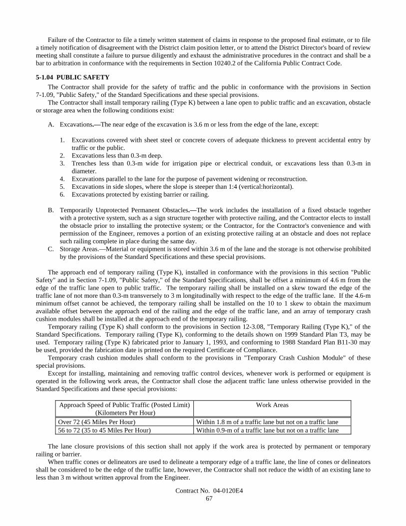
Contract No. 04-0120E467
Failure of the Contractor to file a timely written statement of claims in response to the proposed final estimate, or to filea timely notification of disagreement with the District claim position letter, or to attend the District Director's board of reviewmeeting shall constitute a failure to pursue diligently and exhaust the administrative procedures in the contract and shall be abar to arbitration in conformance with the requirements in Section 10240.2 of the California Public Contract Code.
5-1.04 PUBLIC SAFETYThe Contractor shall provide for the safety of traffic and the public in conformance with the provisions in Section
7-1.09, "Public Safety," of the Standard Specifications and these special provisions.The Contractor shall install temporary railing (Type K) between a lane open to public traffic and an excavation, obstacle
or storage area when the following conditions exist:
A. Excavations.—The near edge of the excavation is 3.6 m or less from the edge of the lane, except:
1. Excavations covered with sheet steel or concrete covers of adequate thickness to prevent accidental entry bytraffic or the public.
2. Excavations less than 0.3-m deep.3. Trenches less than 0.3-m wide for irrigation pipe or electrical conduit, or excavations less than 0.3-m in
diameter.4. Excavations parallel to the lane for the purpose of pavement widening or reconstruction.5. Excavations in side slopes, where the slope is steeper than 1:4 (vertical:horizontal).6. Excavations protected by existing barrier or railing.
B. Temporarily Unprotected Permanent Obstacles.—The work includes the installation of a fixed obstacle togetherwith a protective system, such as a sign structure together with protective railing, and the Contractor elects to installthe obstacle prior to installing the protective system; or the Contractor, for the Contractor's convenience and withpermission of the Engineer, removes a portion of an existing protective railing at an obstacle and does not replacesuch railing complete in place during the same day.
C. Storage Areas.—Material or equipment is stored within 3.6 m of the lane and the storage is not otherwise prohibitedby the provisions of the Standard Specifications and these special provisions.
The approach end of temporary railing (Type K), installed in conformance with the provisions in this section "PublicSafety" and in Section 7-1.09, "Public Safety," of the Standard Specifications, shall be offset a minimum of 4.6 m from theedge of the traffic lane open to public traffic. The temporary railing shall be installed on a skew toward the edge of thetraffic lane of not more than 0.3-m transversely to 3 m longitudinally with respect to the edge of the traffic lane. If the 4.6-mminimum offset cannot be achieved, the temporary railing shall be installed on the 10 to 1 skew to obtain the maximumavailable offset between the approach end of the railing and the edge of the traffic lane, and an array of temporary crashcushion modules shall be installed at the approach end of the temporary railing.
Temporary railing (Type K) shall conform to the provisions in Section 12-3.08, "Temporary Railing (Type K)," of theStandard Specifications. Temporary railing (Type K), conforming to the details shown on 1999 Standard Plan T3, may beused. Temporary railing (Type K) fabricated prior to January 1, 1993, and conforming to 1988 Standard Plan B11-30 maybe used, provided the fabrication date is printed on the required Certificate of Compliance.
Temporary crash cushion modules shall conform to the provisions in "Temporary Crash Cushion Module" of thesespecial provisions.
Except for installing, maintaining and removing traffic control devices, whenever work is performed or equipment isoperated in the following work areas, the Contractor shall close the adjacent traffic lane unless otherwise provided in theStandard Specifications and these special provisions:
Approach Speed of Public Traffic (Posted Limit) (Kilometers Per Hour)
Work Areas
Over 72 (45 Miles Per Hour) Within 1.8 m of a traffic lane but not on a traffic lane56 to 72 (35 to 45 Miles Per Hour) Within 0.9-m of a traffic lane but not on a traffic lane
The lane closure provisions of this section shall not apply if the work area is protected by permanent or temporaryrailing or barrier.
When traffic cones or delineators are used to delineate a temporary edge of a traffic lane, the line of cones or delineatorsshall be considered to be the edge of the traffic lane, however, the Contractor shall not reduce the width of an existing lane toless than 3 m without written approval from the Engineer.
Contract No. 04-0120E468
When work is not in progress on a trench or other excavation that required closure of an adjacent lane, the traffic conesor portable delineators used for the lane closure shall be placed off of and adjacent to the edge of the traveled way. Thespacing of the cones or delineators shall be not more than the spacing used for the lane closure.
Suspended loads or equipment shall not be moved nor positioned over public traffic or pedestrians.Full compensation for conforming to the provisions in this section "Public Safety," including furnishing and installing
temporary railing (Type K) and temporary crash cushion modules, shall be considered as included in the contract prices paidfor the various items of work involved and no additional compensation will be allowed therefor.
5-1.05 TESTINGTesting of materials and work shall conform to the provisions in Section 6-3, "Testing," of the Standard Specifications
and these special provisions.Whenever the provisions of Section 6-3.01, "General," of the Standard Specifications refer to tests or testing, it shall
mean tests to assure the quality and to determine the acceptability of the materials and work.The Engineer will deduct the costs for testing of materials and work found to be unacceptable, as determined by the tests
performed by the Department, and the costs for testing of material sources identified by the Contractor which are not used forthe work, from moneys due or to become due to the Contractor. The amount deducted will be determined by the Engineer.
5-1.06 REMOVAL OF ASBESTOS AND HAZARDOUS SUBSTANCESWhen the presence of asbestos or hazardous substances are not shown on the plans or indicated in the specifications and
the Contractor encounters materials which the Contractor reasonably believes to be asbestos or a hazardous substance asdefined in Section 25914.1 of the Health and Safety Code, and the asbestos or hazardous substance has not been renderedharmless, the Contractor may continue work in unaffected areas reasonably believed to be safe. The Contractor shallimmediately cease work in the affected area and report the condition to the Engineer in writing.
In conformance with Section 25914.1 of the Health and Safety Code, removal of asbestos or hazardous substancesincluding exploratory work to identify and determine the extent of the asbestos or hazardous substance will be performed byseparate contract.
If delay of work in the area delays the current controlling operation, the delay will be considered a right of way delayand the Contractor will be compensated for the delay in conformance with the provisions in Section 8-1.09, "Right of WayDelays," of the Standard Specifications.
5-1.07 YEAR 2000 COMPLIANCEThis contract is subject to Year 2000 Compliance for automated devices in the State of California.Year 2000 compliance for automated devices in the State of California is achieved when embedded functions have or
create no logical or mathematical inconsistencies when dealing with dates prior to and beyond 1999. The year 2000 isrecognized and processed as a leap year. The product shall operate accurately in the manner in which the product wasintended for date operation without requiring manual intervention.
The Contractor shall provide the Engineer a Certificate of Compliance from the manufacturer in conformance with theprovisions in Section 6-1.07, "Certificates of Compliance," of the Standard Specifications for all automated devicesfurnished for the project.
5-1.075 BUY AMERICA REQUIREMENTSAttention is directed to the "Buy America" requirements of the Surface Transportation Assistance Act of 1982 (Section
165) and the Intermodal Surface Transportation Efficiency Act of 1991 (ISTEA) Sections 1041(a) and 1048(a), and theregulations adopted pursuant thereto. In conformance with the law and regulations, all manufacturing processes for steel andiron materials furnished for incorporation into the work on this project shall occur in the United States; with the exceptionthat pig iron and processed, pelletized and reduced iron ore manufactured outside of the United States may be used in thedomestic manufacturing process for such steel and iron materials. The application of coatings, such as epoxy coating,galvanizing, painting, and other coatings that protect or enhance the value of steel or iron materials shall be considered amanufacturing process subject to the "Buy America" requirements.
A Certificate of Compliance conforming to the provisions in Section 6-1.07, "Certificates of Compliance," of theStandard Specifications shall be furnished for steel and iron materials. The certificates, in addition to certifying that thematerials comply with the specifications, shall specifically certify that all manufacturing processes for the materials occurredin the United States, except for the above exceptions.
Attention is directed to the provisions in "Alternate Bids," and "Award and Execution of Contract," of these specialprovisions regarding waiver of this section "Buy America Requirements" depending on the total bids submitted for thealternatives, in conformance with the regulations.
Contract No. 04-0120E469
Attention is directed to the provision in Section 7-1.01, "Laws to be Observed," of the Standard Specifications. Tariffsand trade agreements are implemented by Federal laws and regulations, and therefore shall not revise the provisions of thecontract or the prices paid for the contract items.
5-1.08 SUBCONTRACTOR AND DBE RECORDSThe Contractor shall maintain records showing the name and business address of each first-tier subcontractor. The
records shall also show the name and business address of every DBE subcontractor, DBE vendor of materials and DBEtrucking company, regardless of tier. The records shall show the date of payment and the total dollar figure paid to all ofthese firms. DBE prime contractors shall also show the date of work performed by their own forces along with thecorresponding dollar value of the work.
Upon completion of the contract, a summary of these records shall be prepared on Form CEM-2402 (F) and certifiedcorrect by the Contractor or the Contractor's authorized representative, and shall be furnished to the Engineer. The formshall be furnished to the Engineer within 90 days from the date of contract acceptance. $10,000 will be withheld frompayment until the Form CEM-2402 (F) is submitted. The amount will be returned to the Contractor when a satisfactoryForm CEM-2402 (F) is submitted.
Prior to the fifteenth of each month, the Contractor shall submit documentation to the Engineer showing the amount paidto DBE trucking companies listed in the Contractor's DBE information. This monthly documentation shall indicate theportion of the revenue paid to DBE trucking companies which is claimed toward DBE participation. The Contractor shallalso obtain and submit documentation to the Engineer showing the amount paid by DBE trucking companies to all firms,including owner-operators, for the leasing of trucks. The DBE who leases trucks from a non-DBE is entitled to credit onlyfor the fee or commission it receives as a result of the lease arrangement. The records must confirm that the amount of creditclaimed toward DBE participation conforms with Section 2-1.02, "Disadvantaged Business Enterprise," of these specialprovisions.
The Contractor shall also obtain and submit documentation to the Engineer showing the truck number, owner's name,California Highway Patrol CA number, and if applicable, the DBE certification number of the owner of the truck for alltrucks used during that month for which DBE participation will be claimed. This documentation shall be submitted on FormCEM-2404 (F).
5-1.083 DBE CERTIFICATION STATUSIf a DBE subcontractor is decertified during the life of the project, the decertified subcontractor shall notify the
Contractor in writing with the date of decertification. If a subcontractor becomes a certified DBE during the life of theproject, the subcontractor shall notify the Contractor in writing with the date of certification. The Contractor shall furnishthe written documentation to the Engineer.
Upon completion of the contract, Form CEM-2403 (F) indicating the DBE's existing certification status shall be signedand certified correct by the Contractor. The certified form shall be furnished to the Engineer within 90 days from the date ofcontract acceptance.
5-1.086 PERFORMANCE OF DBE SUBCONTRACTORS AND SUPPLIERSThe DBEs listed by the Contractor in response to the provisions in Section 2-1.02B, "Submission of DBE Information,"
and Section 3, "Award and Execution of Contract," of these special provisions, which are determined by the Department tobe certified DBEs, shall perform the work and supply the materials for which they are listed, unless the Contractor hasreceived prior written authorization to perform the work with other forces or to obtain the materials from other sources.
Authorization to use other forces or sources of materials may be requested for the following reasons:
A. The listed DBE, after having had a reasonable opportunity to do so, fails or refuses to execute a written contract,when such written contract, based upon the general terms, conditions, plans and specifications for the project, or onthe terms of such subcontractor's or supplier's written bid, is presented by the Contractor.
B. The listed DBE becomes bankrupt or insolvent.C. The listed DBE fails or refuses to perform the subcontract or furnish the listed materials.D. The Contractor stipulated that a bond was a condition of executing a subcontract and the listed DBE subcontractor
fails or refuses to meet the bond requirements of the Contractor.E. The work performed by the listed subcontractor is substantially unsatisfactory and is not in substantial conformance
with the plans and specifications, or the subcontractor is substantially delaying or disrupting the progress of thework.
F. It would be in the best interest of the State.
Contract No. 04-0120E470
The Contractor shall not be entitled to any payment for such work or material unless it is performed or supplied by thelisted DBE or by other forces (including those of the Contractor) pursuant to prior written authorization of the Engineer.
5-1.09 SUBCONTRACTINGAttention is directed to the provisions in Section 8-1.01, "Subcontracting," of the Standard Specifications, and Section 2,
"Proposal Requirements and Conditions," and Section 3, "Award and Execution of Contract," of these special provisions.Pursuant to the provisions of Section 1777.1 of the Labor Code, the Labor Commissioner publishes and distributes a list
of contractors ineligible to perform work as a subcontractor on a public works project. This list of debarred contractors isavailable from the Department of Industrial Relations web site at:
http://www.dir.ca.gov/DLSE/Debar.html.
The first sentence in the third paragraph of Section 8-1.01, "Subcontracting," of the Standard Specifications shall notapply.
The Contractor shall perform with the Contractor's own organization contract work amounting to not less than 30percent of the original total contract price, except that any designated "Specialty Items" may be performed by subcontractand the amount of "Specialty Items" so performed may be deducted from the original total contract price before computingthe amount of work required to be performed by the Contractor with the Contractor's own organization.
Each subcontract and any lower tier subcontract that may in turn be made shall include the "Required ContractProvisions Federal-Aid Construction Contracts" in Section 14 of these special provisions. This requirement shall beenforced as follows:
A. Noncompliance shall be corrected. Payment for subcontracted work involved will be withheld from progresspayments due, or to become due, until correction is made. Failure to comply may result in termination of thecontract.
In conformance with the Federal DBE regulations Sections 26.53(f)(1) and 26.53(f)(2) Part 26, Title 49 CFR:
A. The Contractor shall not terminate for convenience a DBE subcontractor listed in response to Section 2-1.02B,"Submission of DBE Information," and then perform that work with its own forces, or those of an affiliate withoutthe written consent of the Department, and
B. If a DBE subcontractor is terminated or fails to complete its work for any reason, the Contractor will be required tomake good faith efforts to substitute another DBE subcontractor for the original DBE subcontractor, to the extentneeded to meet the contract goal.
The requirement in Section 2-1.02, "Disadvantaged Business Enterprise (DBE)," of these special provisions that DBEsmust be certified on the date bids are opened does not apply to DBE substitutions after award of the contract.
5-1.10 PROMPT PROGRESS PAYMENT TO SUBCONTRACTORSAttention is directed to the provisions in Sections 10262 and 10262.5 of the Public Contract Code and Section 7108.5 of
the Business and Professions Code concerning prompt payment to subcontractors.
5-1.102 PROMPT PAYMENT OF WITHHELD FUNDS TO SUBCONTRACTORSThe Contractor shall return all moneys withheld in retention from the subcontractor within 30 days after receiving
payment for work satisfactorily completed, even if the other contract work is not completed and has not been accepted inconformance with Section 7-1.17, "Acceptance of Contract," of the Standard Specifications. This requirement shall not beconstrued to limit or impair any contractual, administrative, or judicial remedies otherwise available to the Contractor orsubcontractor in the event of a dispute involving late payment or nonpayment by the Contractor or deficient subcontractperformance or noncompliance by a subcontractor.
5-1.103 RECORDSThe Contractor shall maintain cost accounting records for the contract pertaining to, and in such a manner as to provide
a clear distinction between, the following six categories of costs of work during the life of the contract:
A. Direct costs of contract item work.

Contract No. 04-0120E471
B. Direct costs of changes in character in conformance with Section 4-1.03C, "Changes in Character of Work," of theStandard Specifications.
C. Direct costs of extra work in conformance with Section 4-1.03D, "Extra Work," of the Standard Specifications.D. Direct costs of work not required by the contract and performed for others.E. Direct costs of work performed under a notice of potential claim in conformance with the provisions in Section
9-1.04, "Notice of Potential Claim," of the Standard Specifications.F. Indirect costs of overhead.
Cost accounting records shall include the information specified for daily extra work reports in Section 9-1.03C,"Records," of the Standard Specifications. The requirements for furnishing the Engineer completed daily extra work reportsshall only apply to work paid for on a force account basis.
The cost accounting records for the contract shall be maintained separately from other contracts, during the life of thecontract, and for a period of not less than 3 years after the date of acceptance of the contract. If the Contractor intends to fileclaims against the Department, the Contractor shall keep the cost accounting records specified above until completeresolution of all claims has been reached.
5-1.11 PARTNERINGThe State will promote the formation of a "Partnering" relationship with the Contractor in order to effectively complete
the contract to the benefit of both parties. The purpose of this relationship is to maintain a cooperative communication and tomutually resolve conflicts at the lowest responsible management level.
The Contractor may request the formation of a "Partnering" relationship by submitting a request in writing to theEngineer after approval of the contract. If the Contractor's request for "Partnering" is approved by the Engineer, schedulingof a "Partnering Workshop," selecting the "Partnering" facilitator and workshop site, and other administrative details shall beas agreed to by both parties. If agreed to by the parties, additional "Partnering Workshops" will be conducted as neededthroughout the life of the contract.
A one-day "Training in Partnering Concepts" session will be conducted regardless of whether the Contractor requeststhe formation of a "Partnering" relationship. The "Training in Partnering Concepts" session will be conducted locally for theContractor's and the Engineer's project representatives. The Contractor shall be represented by a minimum of 2representatives, one being the Contractor's authorized representative pursuant to Section 5-1.06, "Superintendence," of theStandard Specifications. Scheduling of the "Training in Partnering Concepts" session and selection of the trainer andtraining site shall be determined cooperatively by the Contractor and the Engineer. Further, a one-day "CommunityPartnering Workshop" Partnering workshop to address issues of concern to the communities of Oakland and San Franciscoand the City of Oakland and City and County of San Francisco. If, upon the Contractor's request, "Partnering" is approvedby the Engineer, the "Training in Partnering Concepts" session and "Community Partnering Workhop"shall be conductedprior to the initial "Partnering Workshop."
The costs involved in providing the "Training in Partnering Concepts" and "Community Partnering Workshop", thetrainer and training site will be borne entirely by the State. The costs will be determined in conformance with the provisionsin Section 9-1.03B, "Work Performed by Special Forces or Other Special Services," of the Standard Specifications, andpaying to the Contractor the sum of that cost, except no markups will be allowed.
The costs involved in providing the "Partnering Workshop" facilitator and workshop site will be borne equally by theState and the Contractor. The division of cost will be made by determining the cost in providing the "Partnering Workshop"facilitator and workshop site in conformance with the provisions in Section 9-1.03B, "Work Performed by Special Forces orOther Special Services," of the Standard Specifications, and paying to the Contractor one-half of that cost, except nomarkups will be allowed.
All other costs associated with "Training in Partnering Concepts" and "Partnering Workshops" will be borne separatelyby the party incurring the costs, such as wages and travel expenses, and no additional compensation will be allowed therefor.
The establishment of a "Partnering" relationship will not change or modify the terms and conditions of the contract andwill not relieve either party of the legal requirements of the contract.
5-1.114 CORRIDOR VALUE ANALYSISAttention is directed to Section 10-1.06, "Cooperation," of these special provisions.The Contractor shall attend a "SFOBB Corridor Value Analysis" workshop on a semi-annual basis until project
acceptance. It is anticipated that one or more other contractors, pursuant to said Section 10-1.06, will also participate in theworkshop. The purpose for having a workshop is to identify value enhancing opportunities and to consider modifications tothe plans and specifications of any and all corridor projects that will reduce either the total corridor cost, time of constructionor traffic congestion, without impairing, in any manner, the essential functions or characteristics of this contract or any othercorridor construction contract including, but not limited to, service life, economy of operation, ease of maintenance, benefits
Contract No. 04-0120E472
to the travelling public, desired appearance, or design and safety standards. The workshop shall focus on potential enhancingopportunities which would result in any and all corridor construction contractors meeting their respective contractualmilestones, early completion of any and all corridor construction contract's designated portions of work and projectcompletion dates, and mitigating delays to any and all corridor construction contracts.
Scheduling of a workshop, selecting the facilitator and workshop site, and other administrative details shall bedetermined cooperatively by the Contractor and the Engineer. The workshop shall be conducted in conformance with themethodology described in the Department's "Value Analysis Team Guide" available at the Department's web site at:
http://www.dot.ca.gov/hq/oppd/value/
The facilitator shall be a Certified Value Specialist (CVS) as recognized by the Society of American Value Engineers(SAVE) International, which may be contacted as follows:
SAVE International, 60 Revere Drive, Northbrook, IL 60062Telephone 1-847-480-1730, FAX 1-847-480-9282
In addition to the above provisions relative to the semi-annual "SFOBB Corridor Value Analysis" workshop, theContractor may submit to the Engineer, in writing, a request for a project-specific "Value Analysis" workshop with no othercorridor construction contractors in attendance. To maximize the potential benefits of a workshop, the request should besubmitted to the Engineer early in the project after approval of the contract.
The Contractor may submit recommendations resulting from a "Value Analysis" workshop for approval by the Engineeras cost reduction incentive proposals in conformance with the provisions in Section 5-1.14, "Cost Reduction Incentive," ofthe Standard Specifications.
The costs involved in providing the "Value Analysis" facilitator and workshop site for the semi-annual "SFOBBCorridor Value Analysis" workshop shall be borne by the State in conformance with the provisions in Section 9-1.03B,"Work Performed by Special Forces or Other Special Services," of the Standard Specifications, except no markups will beallowed.
The costs involved in providing the "Value Analysis" facilitator and workshop site for the project-specific "ValueAnalysis" workshop shall be borne equally by the State and the Contractor. The division of cost will be made by determiningthe cost in providing the "Value Analysis" facilitator and workshop site in conformance with the provisions in Section 9-1.03B, "Work Performed by Special Forces or Other Special Services," of the Standard Specifications, and paying to theContractor one-half of that cost, except no markups will be allowed.
All other costs including, but not limited to, wages and travel expenses, associated with the semi-annual "SFOBBCorridor Value Analysis" workshop and "Value Analysis" workshop will be borne separately by the party incurring thecosts, and no additional compensation will be allowed therefor.
5-1.12 PROJECT INFORMATIONThe data and information furnished or referred to below is for the bidders' or contractors' information, is available on CD
ROMs. The data and information is subject to the conditions and limitations set forth in Section 2-1.03, "Examination ofPlans, Specifications, Contract, and Site of Work," and Section 6-2, "Local Materials," of the Standard Specifications.Bidders and contractors may request data and information in conformance to the procedures available at the office of thedistrict for which the work is situated, and the Transportation Laboratory.
INFORMATION HANDOUT
Structure Materials InformationData and information shown in the Materials Information are:
A. Project specific design criteria "Design Criteria, San Francisco-Oakland Bay Bridge East Span Seismic SafetyProject, Self Anchored Suspension Bridge, dated April, 2002 by T. Y. Lin International/Moffatt & NicholEngineers, a Joint Venture"
B. Foundation RecommendationsC. Mass Concrete Report dated January 25, 2001 by Ric Maggenti, P.E. Materials & Research Engineer of Caltrans.
Appendix to Mass Concrete Report: Mass Concrete Pours at Dublin 580/680 InterchangeD. US Army Corps of Engineers Method CRD-C39-81, "Test Method for Coefficient of Linear Thermal Expansion of
Concrete"E. Notification of California Department of Transportation Qualification Requirement for Ultrasonic Testing Personnel

Contract No. 04-0120E473
Geotechnical Materials InformationData and information shown in the Materials Information are:
A. Pile Installation Demonstration Project (PIDP) Geotechnical Report: Main Text & AppendicesB. Ground Motion Report: Main Text and AppendicesC. Final Marine Geophysical Survey Report:
Volume-1, Main Text and AppendicesD. Final Marine Geotechnical Site Characterization Report:
Volume-1, Main Text and Illustrations. Volume-2A through Volume-2HE. Phase-I Subcontractor Reports:
Volume-1 through Volume-4F. Phase-II Subcontractor Reports:
Volume-1 through Volume-3G. Final Yerba Buena Island Geotechnical Site Characterization Report:
Volume-1, Main Text, Volume-2 through 4H. Final Geotechnical Foundation Report for the Yerba Buena Island Approach and Main SpanI. Sand Blasting Report
District Materials InformationItems shown in the Materials Information are:
A. Regulation, Permits, agreement, consultation letter, Biological Opinion, or Act:
1- California Department of Fish and Game, Copies of the permit2- California Regional Water Quality Control Board, Copies of the Order and the Waste Discharge Requirements,
and RWQCB 401 Certification3- United States Army Corps of Engineers, Copies of the permit4- San Francisco Bay Conservation Development Commission, Amendment No. 65- United States Coast Guard, a USCG Bridge Permit6- United States Fish and Wildlife Service, Copies of the Biological Opinion; CDFG 2081 Incidental Take
Statement7. USFWS Biological Opinion for brown pelicans and least terns;8- NMFS- Biological Opinion9. Caltrans letters to the Dredged Material Management Office with draft disposal plan;
B. Archaeological Survey ReportsC. Underwater Debris: Phase I Archaeological Survey Report - Maritime Archaeology", and "Addendum
Archaeological Survey Report - Maritime Archaeology."
D. SFOBB East Span Survey Info (revised 12/31/2002)E. Private Aid to Navigation Sample FormF. Jones Act (Samsung Heavy Industrial 300MT Floating Crane may be used in the constructionG. United States Coast Guard Licenses
Items available for inspection, upon written request, at the office of the Duty Senior at the District 4 Office, 111 GrandAvenue, Oakland, CA 94612, email: [email protected], telephone number (510) 286-5209 are as follows:
A. Final Environmental Impact Statement/California Environmental Quality Act (CEQA) Statutory Exemption andRecord of Decision;
B. BCDC Permit Application;C. Application for Water Quality Certification from the RWQCB;D. ACOE 404 Permit Application;E. USCG Permit Application;F. Soil samples and rock cores
Contract No. 04-0120E474
5-1.13 NON-JOURNEY PERSON TRAINING PROGRAMThis provision supplements the Federal Trainee Program as part of the Contractor's equal employment opportunity
affirmative action program.In addition to the Federal Trainee Program, the Contractor may elect to provide training for apprentices or trainees,
herein referred to as trainees, under the contract as established in this special provision. The Contractor shall notify theEngineer in writing of the Contractor's intent to provide training under this special provision no later than 20 calendar daysfollowing award of contract.
If the Contractor elects to provide on-the job training in accordance with this special provision, the goal for the numberof trainees to be trained under the requirements of this special provision will be determined by the ratios approved by theState Department of Industrial Relations, Division of Apprenticeship Standards (DAS). The number of trainees shall bedistributed among the work classifications on the basis of the Contractor's needs and availability of journeypersons in thevarious classifications within a reasonable area of recruitment.
In the event the Contractor subcontracts a portion of contract work, the Contractor may further assign a portion of thetraining requirements established herein to the subcontractor. Any further assignment of these training requirements by theContractor shall be submitted in writing to the Engineer and an appropriately amended Training Program shall be madeapplicable to such subcontract. Where feasible, 25 percent of trainees in each occupation shall be in their first year ofapprenticeship or training.
Approval or acceptance of a Training Program shall be obtained from the State prior to commencing work on theclassification covered by the program. The Contractor shall also submit to the Engineer the number of trainees to be trainedin each selected classification and training program to be used. The minimum length and type of training for eachclassification will be as established in the Training Program selected by the Contractor and approved by both the State andthe Federal Highway Administration (FHWA). The State and FHWA will approve a program if it is reasonably calculated tomeet the equal employment opportunity obligations of the Contractor and to qualify the average trainee for journeypersonstatus in the classification specified by the end of the training period. Furthermore, training programs registered with theU.S. Department of Labor, Bureau of Apprenticeship and Training, or with the DAS and recognized by the Bureau, andtraining programs approved but not necessarily sponsored by the U.S. Department of Labor, Manpower Administration,Bureau of Apprenticeship and Training shall also be considered acceptable provided they are being administered in a mannerconsistent with the equal employment obligations of Federal-Aid highway construction contracts. Any trainee not enrolledin one of the aforementioned programs shall be paid not less than the prevailing wage at the journeyperson level.Furthermore, the Contractor shall specify the starting time for training in each of the classifications.
The Contractor, upon the start of training under the contract, shall provide the Engineer with following information foreach trainee:
A. NameB. AddressC. Telephone NumberD. Social Security NumberE. Race/Ethnic OriginF. GenderG. Classification to be Trained InH. Status in Training Program (1st half ,third quarter, last quarter)I. Date Training Will Begin.J. The Anticipated Number of Hours Required for Training.K. Classification(s) Previously Trained in and Data Training was Completed.
The Contractor, prior to start of training, shall provide written notice to each person to be trained under this specialprovision of that person's designation as a trainee, the training program and classification under which training will beprovided, the length of the training program, and the hourly wage rate to be paid to the trainee.
No employee shall be employed as a trainee in any classification in which the employee has successfully completed atraining course, or in which the employee has been employed as a journeyperson. The Contractor shall satisfy thisrequirement by including appropriate questions in the employee application or by other suitable means. The Contractor shalldocument the findings in each case.
Except as otherwise noted below, the Contractor will be reimbursed $2.00 per hour of on-site training or work on thiscontract for trainees, in addition to the amount specified in the Federal Trainee Program. This reimbursement may be madeeven though the Contractor receives additional training program funds from other sources, provided such other source doesnot specifically prohibit the Contractor from receiving other reimbursement. Compensation will be extra work, as specified
Contract No. 04-0120E475
in Section 4-1.03D of the Standard Specifications, except no markups will be added. The total amount of compensation shallbe limited to $44,000.
5-1.14 MONITORINGIn addition to the requirements in these special provisions, the Contractor shall designate an officer responsible for
monitoring activities related to DBEs, City and County of San Francisco and Oakland Resources and AffirmativeAction/Equal Employment Opportunity, and to report the employment, business and Affirmative Action/Equal EmploymentOpportunity utilization for the Contractor and subcontractors. The Contractor's officer shall present a monthly report at asingle monthly forum to be conducted at the locations, dates and times designated by the Engineer.
At the first monthly forum, to be held within 20 calendar days following the approval of the contract, the Contractor andeach of the subcontractors performing work of $10,000 or more and working within the first six months of the project shallsubmit the following for information purposes:
1. The Anticipated Workforce Utilization Form. This form shall be based on the total anticipated hours for the project,on a craft-by-craft basis (use Project Special Form 100).
2. The DBE and LBE (Local Business Enterprise) Utilization Form (use Project Special Form 200).3. A bar chart showing the approximate schedule and duration of the work to be performed by the Contractor and each
subcontractor.
The second and subsequent reports shall document on both a monthly and cumulative basis, the following information:
1. For each subcontractor, manufacturer, supplier and trucker, by craft: the items and quantities of work performed,amount and date of compensation paid, status as a DBE, and business address (use Project Special Form 300); and
2. For the Contractor, and for each subcontractor and trucker performing work of $10,000 or more, an updated versionof the Project Special Form 200 which tracks employment status for each craft, including: the number of hoursworked and the total number of employees classified as non-minorities, minorities, male, female, and Oaklandresidents. In addition, provide the city and zip code of legal residence for each trade used (use Project Special Form400).
3. For the Contractor, and for each subcontractor performing work of $10,000 or more, a projection of the workforceto be utilized for the upcoming 30 days (use Special Project Form 100).
At the third monthly forum of the contract, the Contractor shall submit a bar chart showing the approximate craft-by-craft schedule of trades to be utilized on the project. Resources outlined in "Progress Schedule (Critical Path Method)" ofthese special provisions may be utilized to generate and update the bar charts.
All reports shall be written and presented in the number of copies directed by the Engineer for use at the monthly forum,not to exceed 50 copies.
A final report summarizing all previous monthly reports shall be submitted within 30 days after contract acceptance.The Contractor will receive $5,000 for each month in which the Contractor presents a monthly report at the monthly
forum and when the Contractor submits the final report. The amount paid each month for presenting the monthly reports orfor submitting the final report shall include all markups, full compensation for furnishing all labor, materials, tools,equipment and incidentals, and for doing all the work involved in preparing and presenting monthly reports, including copiesof the reports, as specified in these special provisions and as directed by the Engineer.
PROJECT SPECIAL FORMSAttention is directed to "Project Information," of these special provisions, regarding the project special forms 100
through 400. The Contractor designated officer responsible for monitoring activities shall use the project special forms 100through 400 as specified by these special provisions:
PROJECT SPECIAL FORM 100Workforce Utilization FormAffirmative Action and Local Employment Program
PROJECT SPECIAL FORM 200DBE AND LBE UTILIZATION FORM
PROJECT SPECIAL FORM 300Progress Payment Form for
Contract No. 04-0120E476
Subcontractors, Equipment Owner Operators, Suppliers
PROJECT SPECIAL FORM 400Employee City and Zip Code Form
5-1.15 DISPUTE REVIEW BOARDGENERALTo assist in the resolution of disputes or potential claims arising out of the work of this project, a Dispute Review Board,
hereinafter referred to as the "DRB," shall be established by the Engineer and Contractor cooperatively upon approval of thecontract. The DRB is intended to assist the contract administrative claims resolution process as specified in the provisions inSection 9-1.04, "Notice of Potential Claim," and Section 9-1.07B, "Final Payment and Claims," of the StandardSpecifications and these special provisions. The DRB shall not serve as a substitute for provisions in the specifications inregard to filing potential claims. The requirements and procedures established in this section shall be a prerequisite to filinga claim, filing for arbitration, or filing for litigation prior or subsequent to project completion.
The DRB shall be utilized when dispute or potential claim resolution at the project level is unsuccessful. The DRB shallfunction as specified herein until the day of acceptance of the contract, at which time the work of the DRB will cease exceptfor completion of unfinished reports. No DRB dispute meetings shall take place later than 30 days prior to acceptance ofcontract. After acceptance of contract, disputes or potential claims which have followed the dispute resolution processes ofthe Standard Specifications and these special provisions, but have not been resolved, shall be stated or restated by theContractor, in response to the Proposed Final Estimate within the time limits provided in Section 9-1.07B, "Final Paymentand Claims," of the Standard Specifications. The State will review those claims in conformance with the provisions inSection 9-1.07B of the Standard Specifications. Following the adherence to and completion of the contractual administrativeclaims procedure, the Contractor may file for arbitration in conformance with the provisions in Section 9-1.10, "Arbitration,"of the Standard Specifications and these special provisions.
Disputes, as used in this section, shall include differences of opinion, properly noticed as provided hereinafter, betweenthe State and Contractor on matters related to the work and other subjects considered by the State or Contractor, or by both,to be of concern to the DRB on this project, except matters relating to Contractor, subcontractor or supplier potential claimsnot actionable against the Department as specified in these special provisions or quantification of disputes for overhead typeexpenses or costs. Disputes for overhead type expenses or costs shall conform to the requirements of Section 9-1.07B,"Final Payment and Claims," of the Standard Specifications. Whenever the term "dispute" or "disputes" is used herein, itshall be deemed to include potential claims as well as disputes.
The DRB shall serve as an advisory body to assist in the resolution of disputes between the State and the Contractor,hereinafter referred to as the "parties." The DRB shall consider disputes referred to it, and furnish written reports containingfindings and recommendations pertaining to those disputes, to the parties to aid in resolution of the differences betweenthem. DRB findings and recommendations are not binding on the parties.
SELECTION PROCESS, DISCLOSURE AND APPOINTMENTSThe DRB shall consist of one member selected by the State and approved by the Contractor, one member selected by the
Contractor and approved by the State, and a third member selected by the first 2 members and approved by both the Stateand the Contractor. The third member shall act as the DRB Chairperson.
DRB members shall be especially knowledgeable in the type of construction and contract documents potentiallyanticipated by the contract. DRB members shall discharge their responsibilities impartially as an independent body,considering the facts and circumstances related to the matters under consideration, pertinent provisions of the contract andapplicable laws and regulations.
The State and the Contractor shall nominate and approve DRB members in conformance with the terms and conditionsof the Dispute Review Board Agreement and these special provisions, within 45 days of the approval of the contract. Eachparty shall provide written notification to the other of the name of their selected DRB nominee along with the prospectivemember's complete written disclosure statement.
Disclosure statements shall include a resume of the prospective member's experience and a declaration statementdescribing past, present, anticipated, and planned relationships, including indirect relationships through the prospectivemember's primary or full-time employer, to this project and with the parties involved in this construction contract, includingbut not limited to, relevant subcontractors or suppliers to the parties, parties' principals, or parties' counsel. DRB membersshall also include a full disclosure of close professional or personal relationships with all key members of the contract.Objections to nominees must be based on a specific breech or violation of nominee responsibilities or on nomineequalifications under these provisions unless otherwise specified. The Contractor or the State may, on a one-time basis, objectto the other's nominee without specifying a reason and this person will not be selected for the DRB. Another person shallthen be nominated within 15 days.
Contract No. 04-0120E477
The first duty of the State and Contractor selected members of the DRB shall be to select and recommend a prospectivethird DRB member to the parties for final selection and approval. The first 2 DRB members shall proceed with the selectionof the third DRB member immediately upon receiving written notification from the State of their selection, and shall providetheir recommendation simultaneously to the parties within 15 days of the notification.
The first 2 DRB members shall select a third DRB member subject to mutual approval of the parties or may mutuallyconcur on a list of potentially acceptable third DRB members and submit the list to the parties for final selection andapproval of the third member. The goal in the selection of the third member is to complement the professional experience ofthe first 2 members and to provide leadership for the DRB's activities.
The third prospective DRB member shall supply a full disclosure statement to the first 2 DRB members and to theparties prior to appointment.
An impasse shall be considered to have been reached if the parties are unable to approve a third member within 15 daysof receipt of the recommendation of the first 2 DRB members, or if the first 2 DRB members are unable to agree upon arecommendation within their 15 day time limit. In the event of an impasse in selection of third DRB member the State andthe Contractor shall each propose 3 candidates for the third DRB member position. The parties shall select the candidatesproposed under this paragraph from the current list of arbitrators certified by the Public Works Contract ArbitrationCommittee created by Article 7.2 (commencing with Section 10245) of the State Contract Act. The first 2 DRB membersshall then select one of the 6 proposed candidates in a blind draw.
No DRB member shall have prior direct involvement in this contract. No member shall have a financial interest in thiscontract or the parties thereto, within a period of 6 months prior to award of this contract or during the contract, except asfollows:
A. Compensation for services on this DRB.B. Ownership interest in a party or parties, documented by the prospective DRB member, that has been reviewed and
determined in writing by the State to be sufficiently insignificant to render the prospective member acceptable to theState.
C. Service as a member of other Dispute Review Boards on other contracts.D. Retirement payments or pensions received from a party that are not tied to, dependent on or affected by the net
worth of the party.E. The above provisions apply to parties having a financial interest in this contract, including but not limited to
contractors, subcontractors, suppliers, consultants, and legal and business services.
The Contractor or the State may reject any of the three DRB members who fail to fully comply at all times with allrequired employment and financial disclosure conditions of DRB membership as described in the Dispute Review BoardAgreement and as specified herein. A copy of the Dispute Review Board Agreement is included in this section.
The Contractor, the State, and the 3 members of the DRB shall complete and adhere to the Dispute Review BoardAgreement in administration of this DRB within 15 days of the parties' concurrence in the selection of the third member. NoDRB meeting shall take place until the Dispute Review Board Agreement has been signed by all parties. The Stateauthorizes the Engineer to execute and administer the terms of the Agreement. The person(s) designated by the Contractoras authorized to execute contract change orders shall be authorized to execute and administer the terms of this agreement, orto delegate the authority in writing. The operation of the DRB shall be in conformance with the terms of the Dispute ReviewBoard Agreement.
COMPENSATIONThe State and the Contractor shall bear the costs and expenses of the DRB equally. Each DRB member shall be
compensated at an agreed rate of $1,200 per day if time spent per meeting, including on-site time plus one hour of traveltime, is greater than 4 hours. Each DRB member shall be compensated at an agreed rate of $700 per day if time spent permeeting, including on-site time plus one hour of travel time, is less than or equal to 4 hours. The agreed rates shall beconsidered full compensation for on-site time, travel expenses, transportation, lodging, time for travel and incidentals foreach day, or portion thereof, that the DRB member is at an authorized DRB meeting. No additional compensation will bemade for time spent by DRB members in review and research activities outside the official DRB meetings unless that time,(such as time spent evaluating and preparing recommendations on specific issues presented to the DRB), has beenspecifically agreed to in advance by the State and Contractor. Time away from the project, which has been specificallyagreed to in advance by the parties, will be compensated at an agreed rate of $125 per hour. The agreed amount of $125 perhour shall include all incidentals including expenses for telephone, fax, and computer services. Members serving on morethan one DRB involving the Department, regardless of the number of meetings per day, shall not be paid more than the allinclusive rate per day or rate per hour for an individual project. The State will provide, at no cost to the Contractor,administrative services such as conference facilities and secretarial services to the DRB. These special provisions and the
Contract No. 04-0120E478
Dispute Review Board Agreement state the provisions for compensation and expenses of the DRB. DRB members shall becompensated at the same daily and hourly rate. The Contractor shall make direct payments to each DRB member for theirparticipation in authorized meetings and approved hourly rate charges from invoices submitted by each DRB member. TheState will reimburse the Contractor for the State's share of the costs. There will be no markups applied to expensesconnected with the DRB, either by the DRB members or by the Contractor when requesting payment of the State's share ofDRB expenses. Regardless of the DRB recommendation, neither party shall be entitled to reimbursement of DRB costs fromthe other party.
REPLACEMENT OF DRB MEMBERSService of a DRB member may be terminated at any time with not less than 15 days notice as follows:
A. The State may terminate service of the State appointed member.B. The Contractor may terminate service of the Contractor appointed member.C. Upon the written recommendation of the State and Contractor appointed members for the removal of the third
member.D. Upon resignation of a member.E. The State or Contractor may terminate the service of any member who fails to fully comply with all required
employment and financial disclosure conditions of DRB membership
When a member of the DRB is replaced, the replacement member shall be appointed in the same manner as the replacedmember was appointed. The appointment of a replacement DRB member will begin promptly upon determination of theneed for replacement and shall be completed within 15 days. Changes in either of the DRB members chosen by the twoparties will not require re-selection of the third member, unless both parties agree to such re-selection in writing. TheDispute Review Board Agreement shall be amended to reflect the change of a DRB member.
OPERATIONThe following procedure shall be used for dispute resolution:
A. If the Contractor objects to any decision, act or order of the Engineer, the Contractor shall give written notice ofpotential claim in conformance with the provisions in Section 9-1.04, "Notice of Potential Claim," of the StandardSpecifications and these special provisions, including the provision of applicable cost documentation; or file writtenprotests or notices in conformance with the provisions in the Standard Specifications and these special provisions.
B. The Engineer will respond, in writing, to the Contractor's written supplemental notice of potential claim within20 days of receipt of the notice.
C. Within 15 days after receipt of the Engineer's written response, the Contractor shall, if the Contractor still objects,file a written reply with the Engineer, stating clearly and in detail the basis of the objection.
D. Following an objection to the Engineer's written response, the Contractor shall refer the dispute to the DRB if theContractor wishes to further pursue the objection to the Engineer's decision. The Contractor shall make the referralin writing to the DRB, simultaneously copied to the State, within 21 days after receipt of the written response fromthe Engineer. The written dispute referral shall describe the disputed matter in individual discrete segments so thatit will be clear to both parties and the DRB what discrete elements of the dispute have been resolved, and whichremain unresolved, and shall include an estimate of the cost of the affected work and impacts, if any, on projectcompletion.
E. By failing to submit the written notice of referral to the DRB, within 21 days after receipt of the Engineer's writtenresponse to the supplemental notice of potential claim, the Contractor waives future claims and arbitration on thematter in contention.
F. The Contractor and the State shall each be afforded an opportunity to be present and to be heard by the DRB, and tooffer evidence. Either party furnishing written evidence or documentation to the DRB must furnish copies of suchinformation to the other party a minimum of 15 days prior to the date the DRB is scheduled to convene the meetingfor the dispute. Either party shall produce such additional evidence as the DRB may deem necessary to reach anunderstanding and a determination of the dispute. The party furnishing additional evidence shall furnish copies ofsuch additional evidence to the other party at the same time the evidence is provided to the DRB. The DRB shallnot consider evidence not furnished in conformance with the terms specified herein.
G. Upon receipt by the DRB of a written referral of a dispute, the DRB shall convene to review and consider thedispute. The dispute meeting shall be held no earlier than 30 days and no later than 60 days after receipt of thewritten referral unless otherwise agreed to by all parties. The DRB shall determine the time and location of the

Contract No. 04-0120E479
DRB dispute meeting, with due consideration for the needs and preferences of the parties while recognizing theparamount importance of a timely hearing of the dispute.
H. There shall be no participation of either party's attorneys at DRB dispute meetings.I. There shall be no participation of persons who are not directly involved in the contract or who do not have direct
knowledge of the dispute, including but not limited to consultants, except for expert testimony allowed at thediscretion of the DRB and with approval prior to the dispute meeting by both parties.
J. The DRB shall furnish a report, containing findings and recommendations as described in the Dispute ReviewBoard Agreement, in writing to both the State and the Contractor. The DRB may request clarifying information ofeither party within 10 days after the DRB dispute meeting. Requested information shall be submitted to the DRBwithin 10 days of the DRB request. The DRB shall complete its report, including minority opinion, if any, andsubmit it to the parties within 30 days of the DRB dispute meeting, except that time extensions may be granted atthe request of the DRB with the written concurrence of both parties. The report shall include the facts andcircumstances related to the matters under consideration, pertinent provisions of the contract, applicable laws andregulations, and actual costs and time incurred as shown on the Contractor's cost accounting records. The DRBshall make recommendations on the merit of the dispute and, if appropriate, recommend guidelines for determiningcompensation.
K. Within 30 days after receiving the DRB's report, both the State and the Contractor shall respond to the DRB inwriting signifying that the dispute is either resolved or remains unresolved. Failure to provide the written responsewithin the time specified, or a written rejection of the DRB's recommendation or response to a request forreconsideration presented in the report by either party, shall conclusively indicate that the party(s) failing to respondaccepts the DRB recommendation. Immediately after responses have been received from both parties, the DRBshall provide copies of both responses to the parties simultaneously. Either party may request clarification ofelements of the DRB's report from the DRB prior to responding to the report. The DRB shall consider anyclarification request only if submitted within 10 days of receipt of the DRB's report, and if submitted simultaneouslyin writing to both the DRB and the other party. Each party may submit only one request for clarification for anyindividual DRB report. The DRB shall respond, in writing, to requests for clarification within 10 days of receipt ofsuch requests.
L. The DRB's recommendations, stated in the DRB's reports, are not binding on either party. Either party may seek areconsideration of a recommendation of the DRB. The DRB shall only grant a reconsideration based uponsubmission of new evidence and if the request is submitted within the 30-day time limit specified for response to theDRB's written report. Each party may submit only one request for reconsideration regarding an individual DRBrecommendation.
M. If the State and the Contractor are able to resolve their dispute with the aid of the DRB's report, the State andContractor shall promptly accept and implement the recommendations of the DRB. If the parties cannot agree oncompensation within 60 days of the acceptance by both parties of the DRB's recommendation, either party mayrequest the DRB to make a recommendation regarding compensation.
N. The State or the Contractor shall not call DRB members who served on the DRB for this contract as witnesses inarbitration proceedings which may arise from this contract, and all documents created by the DRB shall beinadmissible as evidence in subsequent arbitration proceedings, except the DRB's final written reports on each issuebrought before it.
O. The State and Contractor shall jointly indemnify and hold harmless the DRB members from and against all claims,damages, losses, and expenses, including but not limited to attorney's fees, arising out of and resulting from thefindings and recommendations of the DRB.
P. The DRB members shall have no claim against the State or the Contractor, or both, from claimed harm arising outof the parties' evaluations of the DRB's report.
DISPUTES INVOLVING SUBCONTRACTOR POTENTIAL CLAIMSFor purposes of this section, a "subcontractor potential claim" shall include any potential claim by a subcontractor
(including also any pass through potential claims by a lower tier subcontractor or supplier) against the Contractor that isactionable by the Contractor against the Department which arises from the work, services, or materials provided or to beprovided in connection with the contract. If the Contractor determines to pursue a dispute against the Department thatincludes a subcontractor potential claim, the dispute shall be processed and resolved in conformance with these specialprovisions and in conformance with the following:
A. The Contractor shall identify clearly in submissions pursuant to this section, that portion of the dispute that involvesa subcontractor potential claim or potential claims.
Contract No. 04-0120E480
B. The Contractor shall include, as part of its submission pursuant to Step D above, a certification (False Claims ActCertification) by the subcontractor's or supplier's officer, partner, or authorized representative with authority to bindthe subcontractor and with direct knowledge of the facts underlying the subcontractor potential claim. TheContractor shall submit a certification that the subcontractor potential claim is acknowledged and forwarded by theContractor. The form for these certifications is available from the Engineer.
C. At DRB dispute meetings involving one or more subcontractor potential claims, the Contractor shall require thateach subcontractor involved in the dispute have present an authorized representative with actual knowledge of thefacts underlying the subcontractor potential claim to assist in presenting the subcontractor potential claim and toanswer questions raised by the DRB members or the Department's representatives.
D. Failure by the Contractor to declare a subcontractor potential claim on behalf of its subcontractor (including lowertier subcontractors' and suppliers' pass through potential claims) at the time of submission of the Contractor'spotential claims, as provided hereunder, shall constitute a release of the State by the Contractor of suchsubcontractor potential claim.
E. The Contractor shall include in all subcontracts under this contract that subcontractors and suppliers of any tier (a)agree to submit subcontractor potential claims to the Contractor in a proper form and in sufficient time to allowprocessing by the Contractor in conformance with the Dispute Review Board resolution specifications; (b) agree tobe bound by the terms of the Dispute Review Board provisions to the extent applicable to subcontractor potentialclaims; (c) agree that, to the extent a subcontractor potential claim is involved, completion of all steps requiredunder these Dispute Review Board special provisions shall be a condition precedent to pursuit by the subcontractorof other remedies permitted by law, including without limitation of a lawsuit against the Contractor; and (d) agreethat the existence of a dispute resolution process for disputes involving subcontractor potential claims shall not bedeemed to create any claim, right, or cause of action by any subcontractor or supplier against the Department.
Notwithstanding the foregoing, this Dispute Review Board special provision shall not apply to, and the DRB shall nothave the authority to consider, subcontractor potential claims between the subcontractor(s) or supplier(s) and the Contractorthat are not actionable by the Contractor against the Department.
RETENTIONFailure of the Contractor to nominate and approve DRB members in conformance with the terms and conditions of the
Dispute Review Board Agreement and these special provisions shall result in the retention of 25 percent of the estimatedvalue of all work performed during each estimate period in which the Contractor fails to comply with the requirements ofthis section as determined by the Engineer. DRB retentions will be released for payment on the next monthly estimate forpartial payment following the date that the Contractor has nominated and approved DRB members and no interest will bedue the Contractor.
Contract No. 04-0120E481
DISPUTE REVIEW BOARD AGREEMENTA copy of the "Dispute Review Board Agreement" to be executed by the Contractor, State and the 3 DRB members after
approval of the contract follows:
Form 6202 Rev (09/01/02)
DISPUTE REVIEW BOARD AGREEMENT
__________________________(Contract Identification)
Contract No. ___________________
THIS DISPUTE REVIEW BOARD AGREEMENT, hereinafter called "AGREEMENT", made and entered intothis __________ day of _________________, _____, between the State of California, acting through the CaliforniaDepartment of Transportation and the Director of Transportation, hereinafter called the "STATE,"_________________________ ________________________ hereinafter called the "CONTRACTOR," and the DisputeReview Board, hereinafter called the "DRB" consisting of the following members:
_______________________________________________________ ,(Contractor Appointee)
_______________________________________________________ ,(State Appointee)
and ________________________________________________________(Third Person)
WITNESSETH, that
WHEREAS, the STATE and the CONTRACTOR, hereinafter called the "parties," are now engaged in the constructionon the State Highway project referenced above; and
WHEREAS, the special provisions for the above referenced contract provides for the establishment and operation of theDRB to assist in resolving disputes; and
WHEREAS, the DRB is composed of three members, one selected by the STATE, one selected by the CONTRACTOR,and the third member selected by the other two members and approved by the parties;
NOW THEREFORE, in consideration of the terms, conditions, covenants, and performance contained herein, orattached and incorporated and made a part hereof, the STATE, the CONTRACTOR, and the DRB members hereto agree asfollows:
SECTION I DESCRIPTION OF WORKTo assist in the resolution of disputes between the parties, the contract provides for the establishment and the operation
of the DRB. The intent of the DRB is to fairly and impartially consider disputes placed before it and provide writtenrecommendations for resolution of these disputes to both parties. The members of this DRB shall perform the servicesnecessary to participate in the DRB's actions as designated in Section II, Scope of Work.
SECTION II SCOPE OF WORKThe scope of work of the DRB includes, but is not limited to, the following:
A. OBJECTIVEThe principal objective of the DRB is to assist in the timely resolution of disputes between the parties arising from
performance of this contract. It is not intended for either party to default on their normal responsibility to amicably and fairlysettle their differences by indiscriminately assigning them to the DRB. It is intended that the mere existence of the DRB will
Contract No. 04-0120E482
encourage the parties to resolve disputes without resorting to this review procedure. But when a dispute that is seriousenough to warrant the DRB's review does develop, the process for prompt and efficient action will be in place.
B. PROCEDURESThe DRB shall render written reports on disputes between the parties arising from the construction contract. Prior to
consideration of a dispute, the DRB shall establish rules and regulations that will govern the conduct of its business andreporting procedures in conformance with the requirements of the contract and the terms of this AGREEMENT. DRBrecommendations, resulting from its consideration of a dispute, shall be furnished in writing to both parties. Therecommendations shall be based on facts and circumstances involved in the dispute, pertinent contract provisions, applicablelaws and regulations. The recommendations shall find one responsible party in a dispute; shared or "jury" determinationsshall not be rendered. The DRB shall make recommendations on the merit of the dispute, and if appropriate, recommendguidelines for determining compensation. If the parties cannot agree on compensation within 60 days of the acceptance byboth parties of the DRB's recommendation, either party may request the DRB to make a recommendation regardingcompensation.
The DRB shall refrain from officially giving advice or consulting services to anyone involved in the contract. Theindividual members shall act in a completely independent manner and while serving as members of the DRB shall have noconsulting business connections with either party or its principals or attorneys or other affiliates (subcontractors, suppliers,etc.) who have a beneficial interest in the contract.
During scheduled meetings of the DRB as well as during dispute meetings, DRB members shall refrain from expressingopinions on the merits of statements on matters under dispute or potential dispute. Opinions of DRB members expressed inprivate sessions shall be kept strictly confidential. Individual DRB members shall not meet with, or discuss contract issueswith individual parties, except as directed by the DRB Chairperson. Such discussions or meetings shall be disclosed to bothparties. Other discussions regarding the project between the DRB members and the parties shall be in the presence of allthree members and both parties. Individual DRB members shall not undertake independent investigations of any kindpertaining to disputes or potential disputes, except with the knowledge of both parties and as expressly directed by the DRBChairperson.
C. CONSTRUCTION SITE VISITS, PROGRESS MEETINGS AND FIELD INSPECTIONSThe DRB members shall visit the project site and meet with representatives of the parties to keep abreast of construction
activities and to develop familiarity with the work in progress. Scheduled progress meetings shall be held at or near theproject site. The DRB shall meet at least once at the start of the project, and at least once every 4 months thereafter. Thefrequency, exact time, and duration of additional site visits and progress meetings shall be as recommended by the DRB andapproved by the parties consistent with the construction activities or matters under consideration and dispute. Each meetingshall consist of a round table discussion and a field inspection of the work being performed on the contract, if necessary.Each meeting shall be attended by representatives of both parties. The agenda shall generally be as follows:
1. Meeting opened by the DRB Chairperson.2. Remarks by the STATE's representative.3. A description by the CONTRACTOR's representative of work accomplished since the last meeting; the current
schedule status of the work; and a forecast for the coming period.4. An outline by the CONTRACTOR's representative of potential problems and a description of proposed solutions.5. An outline by the STATE's representative of the status of the work as the STATE views it.6. A brief description by the CONTRACTOR's or STATE's representative of potential claims or disputes which have
surfaced since the last meeting.7. A summary by the STATE's representative, the CONTRACTOR's representative, or the DRB of the status of past
disputes and potential claims.
The STATE's representative will prepare minutes of all progress meetings and circulate them for revision and approvalby all concerned within 10 days of the meeting.
The field inspection shall cover all active segments of the work, the DRB being accompanied by both parties'representatives. The field inspection may be waived upon mutual agreement of the parties.
D. DRB CONSIDERATION AND HANDLING OF DISPUTESUpon receipt by the DRB of a written referral of a dispute, the DRB shall convene to review and consider the dispute.
The dispute meeting shall be held no earlier than 30 days and no later than 60 days after receipt of the written referral, unlessotherwise agreed to by all parties. The DRB shall determine the time and location of DRB dispute meetings, with due
Contract No. 04-0120E483
consideration for the needs and preferences of the parties while recognizing the paramount importance of speedy resolutionof issues. No dispute meetings shall take place later than 30 days prior to acceptance of contract.
Normally, dispute meetings shall be conducted at or near the project site. However, any location that would be moreconvenient and still provide required facilities and access to necessary documentation shall be satisfactory.
Both parties shall be given the opportunity to present their evidence at these dispute meetings. It is expressly understoodthat the DRB members are to act impartially and independently in the consideration of the contract provisions, applicablelaws and regulations, and the facts and conditions surrounding any dispute presented by either party, and that therecommendations concerning any such dispute are advisory and nonbinding on the parties.
The DRB may request that written documentation and arguments from both parties be sent to each DRB member,through the DRB Chairperson, for review before the dispute meeting begins. A party furnishing written documentation tothe DRB shall furnish copies of such information to the other party at the same time that such information is supplied to theDRB.
DRB dispute meetings shall be informal. There shall be no testimony under oath or cross-examination. There shall beno reporting of the procedures by a shorthand reporter or by electronic means. Documents and verbal statements shall bereceived by the DRB in conformance with acceptance standards established by the DRB. These standards need not complywith prescribed legal laws of evidence.
The third DRB member shall act as Chairperson for dispute meetings and all other DRB activities. The parties shallhave a representative at all dispute meetings. Failure to attend a duly noticed dispute meeting by either of the parties shall beconclusively considered by the DRB as indication that the non-attending party considers written submittals as their entire andcomplete argument. The claimant shall discuss the dispute, followed by the other party. Each party shall then be allowedone or more rebuttals until all aspects of the dispute are thoroughly covered. DRB members shall ask questions, seekclarification, and request further data from either of the parties as may be necessary to assist in making a fully informedrecommendation. The DRB may request from either party documents or information that would assist the DRB in making itsfindings and recommendations including, but not limited to, documents used by the CONTRACTOR in preparing the bid forthe project. A refusal by a party to provide information requested by the DRB may be considered by the DRB as anindication that the requested material would tend to disprove that party's position. In large or complex cases, additionaldispute meetings may be necessary in order to consider all the evidence presented by both parties. All involved parties shallmaintain the confidentiality of all documents and information, as provided in this AGREEMENT.
During dispute meetings, no DRB member shall express an opinion concerning the merit of any facet of the case. DRBdeliberations shall be conducted in private, with interim individual views kept strictly confidential.
After dispute meetings are concluded, the DRB shall meet in private and reach a conclusion supported by 2 or moremembers. Private sessions of the DRB may be held at a location other than the job site or by electronic conferencing asdeemed appropriate, in order to expedite the process.
The DRB's findings and recommendations, along with discussion of reasons therefor, shall then be submitted as awritten report to both parties. Recommendations shall be based on the pertinent contract provisions, applicable laws andregulations, and facts and circumstances related to the dispute. The report shall be thorough in discussing the factsconsidered, the contract language, law or regulation viewed by the DRB as pertinent to the issues, and the DRB'sinterpretation and philosophy in arriving at its conclusions and recommendations. The DRB's report shall stand on its own,without attachments or appendices. The DRB Chairperson shall furnish a copy of the written recommendation report to theDRB Coordinator, Division of Construction, MS 44, P.O. Box 942874, Sacramento, CA 94274.
With prior written approval of both parties, the DRB may obtain technical services necessary to adequately review thedisputes presented, including audit, geotechnical, schedule analysis and other services. The parties' technical staff maysupply those services as appropriate. The cost of technical services, as agreed to by the parties, shall be borne equally by the2 parties as specified in an approved contract change order. The CONTRACTOR will not be entitled to markups for thepayments made for these services.
The DRB shall resist submittal of incremental portions of information by either party, in the interest of making a fullyinformed decision and recommendation.
The DRB shall make every effort to reach a unanimous decision. If this proves impossible, the dissenting member shallprepare a minority opinion, which shall be included in the DRB's report.
Although both parties should place weight upon the DRB's recommendations, they are not binding. Either party mayappeal a recommendation to the DRB for reconsideration. However, reconsideration shall only be allowed when there isnew evidence to present, and the DRB shall accept only one appeal from each party pertaining to an individual DRBrecommendation. The DRB shall hear appeals in conformance with the terms described in the Section entitled "DisputeReview Board" in the special provisions.
E. DRB MEMBER REPLACEMENT
Contract No. 04-0120E484
Should the need arise to appoint a replacement DRB member, the replacement DRB member shall be appointed in thesame manner as the original DRB members were appointed. The selection of a replacement DRB member shall beginpromptly upon notification of the necessity for a replacement and shall be completed within 15 days. This AGREEMENTshall be amended to indicate change in DRB membership.
SECTION III CONTRACTOR RESPONSIBILITIESThe CONTRACTOR shall furnish to each DRB member one copy of pertinent documents that are or may become
necessary for the DRB to perform their function. Pertinent documents are written notices of potential claim, responses tothose notices, drawings or sketches, calculations, procedures, schedules, estimates, or other documents which are used in theperformance of the work or in justifying or substantiating the CONTRACTOR's position. The CONTRACTOR shall alsofurnish a copy of such pertinent documents to the STATE, in conformance with the terms outlined in the special provisions.
SECTION IV STATE RESPONSIBILITIESThe STATE will furnish the following services and items:
A. CONTRACT RELATED DOCUMENTSThe STATE will furnish to each DRB member one copy of Notice to Contractors and Special Provisions, Proposal and
Contract, Plans, Standard Specifications, and Standard Plans, change orders, written instructions issued by the STATE to theCONTRACTOR, or other documents pertinent to any dispute that has been referred to the DRB and necessary for the DRBto perform its function.
B. COORDINATION AND SERVICESThe STATE, through the Engineer, will, in cooperation with the CONTRACTOR, coordinate the operations of the DRB.
The Engineer will arrange or provide conference facilities at or near the project site and provide secretarial and copyingservices to the DRB without charge to the CONTRACTOR.
SECTION V TIME FOR BEGINNING AND COMPLETIONOnce established, the DRB shall be in operation until the day of acceptance of the contract. The DRB members shall not
begin work under the terms of this AGREEMENT until authorized in writing by the STATE.
SECTION VI PAYMENT
A. ALL INCLUSIVE RATE PAYMENTThe STATE and the CONTRACTOR shall bear the costs and expenses of the DRB equally. Each DRB member shall be
compensated at an agreed rate of $1,200 per day if time spent per meeting, including on-site time plus one hour of traveltime, is greater than 4 hours. Each DRB member shall be compensated at an agreed rate of $700 per day if time spent permeeting, including on-site time plus one hour of travel time, is less than or equal to 4 hours. The agreed rates shall beconsidered full compensation for on-site time, travel expenses, transportation, lodging, time for travel and incidentals foreach day, or portion thereof, that the DRB member is at an authorized DRB meeting. No additional compensation will bemade for time spent by DRB members in review and research activities outside the official DRB meetings unless that timehas been specifically agreed to in advance by the STATE and CONTRACTOR. Time away from the project that has beenspecifically agreed to in advance by the parties will be compensated at an agreed rate of $125 per hour. The agreed amountof $125 per hour shall include all incidentals including expenses for telephone, fax, and computer services. Membersserving on more than one DRB involving the State, regardless of the number of meetings per day, shall not be paid more thanthe all inclusive rate per day or rate per hour for an individual project. The STATE will provide, at no cost to theCONTRACTOR, administrative services such as conference facilities and secretarial services to the DRB.
B. PAYMENTSDRB members shall be compensated at the same rate. The CONTRACTOR shall make direct payments to each DRB
member for their participation in authorized meetings and approved hourly rate charges from invoices submitted by eachDRB member. The STATE will reimburse the CONTRACTOR for its share of the costs of the DRB.
The DRB members may submit invoices to the CONTRACTOR for partial payment for work performed and servicesrendered for their participation in authorized meetings not more often than once per month during the progress of the work.The invoices shall be in a format approved by the parties and accompanied by a general description of activities performedduring that billing period. Payment for hourly fees, at the agreed rate, shall not be paid to a DRB member until the amountand extent of those fees are approved by the STATE and CONTRACTOR.

Contract No. 04-0120E485
Invoices shall be accompanied by original supporting documents, which the CONTRACTOR shall include with theextra work billing when submitting for reimbursement of the STATE's share of cost from the STATE. The CONTRACTORwill be reimbursed for one-half of approved costs of the DRB. No markups will be added to the CONTRACTOR's payment.
C. INSPECTION OF COSTS RECORDSThe DRB members and the CONTRACTOR shall keep available for inspection by representatives of the STATE and the
United States, for a period of 3 years after final payment, the cost records and accounts pertaining to this AGREEMENT. Ifany litigation, claim, or audit arising out of, in connection with, or related to this contract is initiated before the expiration ofthe 3-year period, the cost records and accounts shall be retained until such litigation, claim, or audit involving the records iscompleted.
SECTION VII ASSIGNMENT OF TASKS OF WORKThe DRB members shall not assign the work of this AGREEMENT.
SECTION VIII TERMINATION OF DRB MEMBERSDRB members may resign from the DRB by providing not less than 15 days written notice of the resignation to the
STATE and CONTRACTOR. DRB members may be terminated by their original appointing power or by either party, forfailing to fully comply at all times with all required employment and financial disclosure conditions of DRB membership inconformance with the terms of the contract.
SECTION IX LEGAL RELATIONSThe parties hereto mutually understand and agree that the DRB member in the performance of duties on the DRB, is
acting in the capacity of an independent agent and not as an employee of either party.No party to this AGREEMENT shall bear a greater responsibility for damages or personal injury than is normally
provided by Federal or State of California Law.Notwithstanding the provisions of this contract that require the CONTRACTOR to indemnify and hold harmless the
STATE, the parties shall jointly indemnify and hold harmless the DRB members from and against all claims, damages,losses, and expenses, including but not limited to attorney's fees, arising out of and resulting from the findings andrecommendations of the DRB.
SECTION X CONFIDENTIALITYThe parties hereto mutually understand and agree that all documents and records provided by the parties in reference to
issues brought before the DRB, which documents and records are marked "Confidential - for use by the DRB only," shall bekept in confidence and used only for the purpose of resolution of subject disputes, and for assisting in development of DRBfindings and recommendations; that such documents and records will not be utilized or revealed to others, except to officialsof the parties who are authorized to act on the subject disputes, for any purposes, during the life of the DRB. Upontermination of this AGREEMENT, said confidential documents and records, and all copies thereof, shall be returned to theparties who furnished them to the DRB. However, the parties understand that such documents shall be subsequentlydiscoverable and admissible in court or arbitration proceedings unless a protective order has been obtained by the partyseeking further confidentiality.
SECTION XI DISPUTESDisputes between the parties hereto, including disputes between the DRB members and either party or both parties,
arising out of the work or other terms of this AGREEMENT, which cannot be resolved by negotiation and mutualconcurrence between the parties, or through the administrative process provided in the contract, shall be resolved byarbitration as provided in Section 9-1.10, "Arbitration," of the Standard Specifications.
SECTION XII VENUE, APPLICABLE LAW, AND PERSONAL JURISDICTIONIn the event that any party, including an individual member of the DRB, deems it necessary to institute arbitration
proceedings to enforce any right or obligation under this AGREEMENT, the parties hereto agree that such action shall beinitiated in the Office of Administrative Hearings of the State of California. The parties hereto agree that all questions shallbe resolved by arbitration by application of California law and that the parties to such arbitration shall have the right ofappeal from such decisions to the Superior Court in conformance with the laws of the State of California. Venue for thearbitration shall be Sacramento or any other location as agreed to by the parties.
SECTION XIII FEDERAL REVIEW AND REQUIREMENTS

Contract No. 04-0120E486
On Federal-Aid contracts, the Federal Highway Administration shall have the right to review the work of the DRB inprogress, except for private meetings or deliberations of the DRB.
Other Federal requirements in this agreement shall only apply to Federal-Aid contracts.
SECTION XIV CERTIFICATION OF THE CONTRACTOR, THE DRB MEMBERS, AND THE STATEIN WITNESS WHEREOF, the parties hereto have executed this AGREEMENT as of the day and year first above
written.
DRB MEMBER DRB MEMBER
By: _____________________________ By: ______________________________
Title: ____________________________ Title :_____________________________
DRB MEMBER
By :________________________________
Title :_______________________________
CONTRACTOR CALIFORNIA STATE DEPARTMENTOF TRANSPORTATION
By: _____________________________ By: _____________________________
Title: ___________________________ Title: ____________________________
Contract No. 04-0120E487
5-1.16 COST REDUCTION INCENTIVE PROPOSALSCost Reduction Incentive Proposals (CRIP) shall conform to the provisions in Section 5-1.14, "Cost Reduction
Incentive," of the Standard Specifications and these special provisions.Attention is directed to "Description of Bridge Work" of these special provisions for the description of basic design of
the bridge.The sixth paragraph of Section 5-1.14, "Cost Reduction Incentive," of the Standard Specifications shall not apply.The Contractor shall reimburse the Department's costs for investigating and reviewing a CRIP including the preliminary
concept of a CRIP regardless whether it is approved or rejected. The Contractor shall indicate acceptance thereof in writing,and that acceptance shall constitute full authority for the Department to deduct amounts payable to the Department from anymoneys due or that may become due to the Contractor under the contract.
No proposals will be permitted in the following:
A. Structure TypeB. Pier Cross-SectionsC. Pile Dimensions and LayoutD. Footing Type and DimensionsE. Specified Pile Tip ElevationsF. Minimum Hammer EnergyG. Welding Requirements and Procedures
The Contractor shall submit the preliminary concept of proposed CRIP in writing to the Engineer for approval prior toproceeding with the complete CRIP. After submitting the preliminary concept of proposed CRIP, the Contractor shallrequest a meeting with the Engineer to discuss the proposal in concept and to determine whether the cost reduction proposalwill be considered by the Department. Items of discussion will include permit issues, impact on other projects, impact on theproject schedule, traffic considerations, safety and health issues, design criteria, and review times required by the Departmentand other agencies. Determination by the Engineer that a cost reduction proposal will not be considered further will bedeemed rejection of the proposal. The Contractor shall allow 15 working days after the meeting for the Engineer to reviewthe conceptual submittal. Acceptance of a conceptual submittal in no way constitutes approval nor guarantees futureapproval of the Contractor's CRIP.
If the proposed CRIP affects the seismic performance of the structure, as determined by the Engineer, the Contractorshall present the CRIP proposal to the Seismic Safety Peer Review Panel (SSPRP). It is anticipated that this presentation tothe SSPRP will require a 2-month notice and 6 meetings (occurring once a month). The meeting location(s) will be inCalifornia, and the meeting location and schedule will be determined by the SSPRP. The Engineer will not further considersaid CRIP unless it is approved by the SSPRP. The Contractor's cost of preparing the SSPRP presentation and attending theSSPRP meetings and the Department's costs of investigating said proposal, presentation, meeting attendance, andcompensation to the SSPRP, including any portion thereof paid by the Contractor, shall be excluded from consideration indetermining the estimated new savings in construction costs.
No extension of time and no delay will be granted for the development, submittal, investigation, and review of CRIPs.
5-1.17 TIDAL CONDITIONS AND ELEVATION DATUMAttention is directed to Section 2-1.03, "Examination of Plans, Specifications, Contract, and Site of Work," of the
Standard Specifications.Tidal conditions may present significant problems in constructing the work as depicted in the contract plans. Tidal
fluctuations may be severe and different from those shown in published tidal and current data due to differences in datum,winter runoff and other causes. Strong currents exist over portions of the project site. Limited time periods of slack watermay restrict diving and other underwater activities.
The Contractor is responsible for being knowledgeable of such tidal difficulties, and no payment will be made by theState for any costs incurred by the Contractor in connection with the variations in actual tidal or current conditions during thecourse of this contract. Any reference to Mean Higher High and Mean Lower Low tides shall be understood to be anestimate used for permit purposes, actual mean tide data shall be determined by the Contractor.
All vertical control data are based on the National Geodetic Vertical Datum NGVD of 1929.
5-1.18 ELECTRONIC DAILY EXTRA WORK REPORTAttention is directed to Sections 5-1.10, "Equipment and Plants," 7-1.01A(3), "Payroll Records," 9-1.03C, "Records,"
and 9-1.06, "Partial Payments," of the Standard Specifications and these special provisions.
Contract No. 04-0120E488
Daily extra work reports shall be furnished to the Engineer using the Department's electronic extra work billing system.The reports shall conform to the requirements set forth in the "Extra Work Billing System User's Guide." The Guide isavailable from the Department, and is also found on the Internet athttp://www.dot.ca.gov/hq/construc/EWB_INSTRUCTION.pdf. The Department will provide electronic extra work billingsystem accounts to the Contractor's representatives only after they have received training. The Department will providesystem training to the Contractor's authorized representatives within 30 days of the Contractor's request for training.
An account, user identification assigned by the Department, and password used by the Contractor's representative aredeemed to meet the requirement in Section 9-1.03C of the Standard Specifications that daily extra work reports shall besigned by the Contractor or the Contractor's authorized representative.
Daily extra work reports that include materials shall be substantiated by a valid copy of a vendor's invoice as required inSection 9-1.03C, "Records," of the Standard Specifications. Each invoice shall clearly identify the applicable electronicextra work report and the cost of the materials. In addition to postal service and parcel service, invoices may be sent by FAXor as an electronic-mail attachment, if approved by the Engineer.
The Engineer will compare the Engineer's records with the completed electronic daily extra work report. The Engineerwill reject a report that has an error that affects payment, and will indicate the necessary adjustments the Contractor mustmake prior to sending a corrected electronic extra work report. A daily extra work report that the Contractor's representativesends to the Department using the electronic extra work billing system will be deemed to be signed by the Contractor. Adaily extra work report that the Engineer approves using the electronic extra work billing system will be deemed to be signedby the Engineer.
Electronic submittals submitted by the file transfer process shall conform to the Department's specified format. TheContractor is responsible for maintaining the required data file format and requirements in the file transfer process. TheContractor is responsible for maintaining and operating the Contractor's interface with the Department's electronic extra workbilling system.
Full compensation for furnishing daily extra work reports using the Department's electronic extra work billing systemshall be considered as included in the various contract items involved and no separate payment will be made therefor.
5-1.19 AREAS FOR CONTRACTOR'S USEAttention is directed to the requirements specified in Section 7-1.19, "Rights in Land and Improvement," of the Standard
Specifications and these special provisions.The highway right of way shall be used only for purposes that are necessary to perform the required work. The
Contractor shall not occupy the right of way, or allow others to occupy the right of way, for purposes which are notnecessary to perform the required work.
No area is available within the contract limits for the exclusive use of the Contractor. However, temporary storage ofequipment and materials on State property may be arranged with the Engineer, subject to the prior demands of the Statemaintenance forces and to other contract requirements. Use of the Contractor's work areas and other State-owned propertyshall be at the Contractor's own risk. The State shall not be held liable for the damage to or loss of materials or equipmentlocated within these areas.
No area is available at the Port of Oakland Pier 7 for use by the Contractor.Access to the Contractor's area at the east end of YBI will pass through areas designated for use by Contracts 04-
0120P4, 04-0120Q4 and 04-0120R4. Access through these areas will be available to the Contractor, however, access mustbe coordinated with the Engineer and other Contractors.
Contract 04-012024 will be conducting marine operations in areas adjacent to the contract limits. Contractor marineoperations shall be coordinated with the Engineer and Contract 04-012024 contractor, in addition to requirements specifiedelsewhere in these special provisions.
The Contractor’s access to and from the work area may be limited by the closures of the Westbound and Eastbound YBIon-ramps to I-80, Westbound and Eastbound YBI off-ramps from I-80, Macalla Road, Torpedo Factory Road and SouthgateRoad during the contract period. The Contractor will have access to the work during these closures via posted detours.
Toll plaza parking lots shall not be used for the Contractor's employees private vehicles and the Contractors equipmentand vehicles.
The Contractor shall remove the equipment, materials, and rubbish from the work areas and other State-owned propertywhich the Contractor occupies and shall leave the areas in a presentable condition, in conformance with the provisions inSection 4-1.02, "Final Cleaning Up," of the Standard Specifications.
The Contractor shall secure, at the Contractor's own expense, areas required for storage of plant, equipment, andmaterials, or for other purposes if sufficient area is not available to the Contractor within the contract limits.
Contract No. 04-0120E489
5-1.20 UTILITIESThe Contractor shall make arrangements to obtain electrical power, water or compressed air or other utilities required for
the Contractor's operations and shall make and maintain the necessary service connections at the Contractor's own expense.
5-1.21 SANITARY PROVISIONSState sanitary facilities will not be available for use by the Contractor's employees.
5-1.22 BRIDGE TOLLSToll-free passage on the San Francisco-Oakland Bay Bridge will be granted only for cars, trucks and special
construction equipment which are clearly marked on the exterior with the Contractor's identification and which are beingoperated by the Contractor exclusively for the project, and which are used for the purpose of transporting materials andworkers directly to and from the project site.
The Contractor shall make application to the Engineer in advance for toll-free passage. The Contractor will be heldaccountable for the proper use of passes issued, and upon completion of the work, shall return unused passes to the Engineer.
Attention is directed to Section 23302, "Evasion of Toll," of the Vehicle Code.
5-1.23 PERMITS AND LICENSESAttention is directed to Section 7-1.04, "Permits and Licenses," of the Standard Specifications and these special
provisions.The Department has obtained the following permits for this project:
A. California Regional Water Quality Control Board (RWQCB)B. U.S. Army Corps of Engineers (ACOE)C. San Francisco Bay Conservation Development Commission (BCDC)D. United States Coast Guard (USCG)E. California Department of Fish and Game (CDFG)
Copies of these permits can be obtained at the Department of Transportation, Plans and Bid Documents Section, MS 26,1120 N Street, Room 200, Sacramento, CA 95814, Telephone (916) 654-4490 or may be seen and are available forinspection at the office of the Duty Senior, District 04 Office, 111 Grand Avenue, Oakland, CA 94612, email:[email protected], telephone number (510) 286-5209.
A CD with the RWQCB, ACOE, BCDC, USCG and the CDFG permits has been made part of the information handoutthat is available to the Contractor.
Full compensation for conforming to the requirements in these permits shall be considered as included in the prices paidfor the various contract items of work and no additional compensation will be allowed therefor.
5-1.24 FORCE ACCOUNT PAYMENTThe second, third and fourth paragraphs of Section 9-1.03A, "Work Performed by Contractor," in the Standard
Specifications, shall not apply.Attention is directed to "Time-Related Overhead" of these special provisions.To the total of the direct costs for work performed on a force account basis, computed as provided in Sections
9-1.03A(1), "Labor," 9-1.03A(2), "Materials," and 9-1.03A(3), "Equipment Rental," of the Standard Specifications, therewill be added the following markups:
Cost Percent MarkupLabor 28Materials 10Equipment Rental 10
The above markups shall be applied to work performed on a force account basis,regardless of whether the work revises the current contract completion date.
The above markups, together with payments made for time-related overhead pursuant to "Time-Related Overhead" ofthese special provisions, shall constitute full compensation for all overhead costs for work performed on a force accountbasis. These overhead costs shall be deemed to include all items of expense not specifically designated as cost or equipmentrental in conformance with the provisions in Sections 9-1.03A(1), "Labor," 9-1.03A(2), "Materials," and 9-1.03A(3),"Equipment Rental," of the Standard Specifications. The total payment made as provided above and in the first paragraph of
Contract No. 04-0120E490
Section 9-1.03A, "Work Performed by Contractor," of the Standard Specifications shall be deemed to be the actual cost ofthe work performed on a force account basis, and shall constitute full compensation therefor.
Full compensation for overhead costs for work performed on a force account basis, and for which no adjustment is madeto the lump sum price bid for time-related overhead conforming to the provisions in "Time-Related Overhead" of thesespecial provisions, shall be considered as included in the markups specified above, and no additional compensation will beallowed therefor.
When extra work to be paid for on a force account basis is performed by a subcontractor, approved in conformance withthe provisions in Section 8-1.01, "Subcontracting," of the Standard Specifications, an additional markup of 7 percent will beadded to the total cost of that extra work including all markups specified in this section "Force Account Payment". Theadditional 7 percent markup shall reimburse the Contractor for additional administrative costs, and no other additionalpayment will be made by reason of performance of the extra work by a subcontractor.
5-1.245 FOREIGN FABRICATIONAttention is directed to Section 6-1.08, "Foreign Materials," of the Standard Specifications and these special provisions.The second paragraph of Section 6-1.08, "Foreign Materials," in the Standard Specifications, shall not apply.It shall be the Contractor's responsibility to deliver materials obtained from outside of the United States to the point of
entry into the continental United States in sufficient time to permit timely delivery to the job site.To facilitate discussion between Department and Contractor representatives during materials and fabrication inspections
and audits that occur outside the United States, where English is not fluently spoken by onsite representatives, the Contractorshall ensure that a translator is available at the facility at all times when the Department's quality assurance representativesare present.
Full compensation for ensuring that the translator is available shall be considered as included in the contract prices paidfor the various contract items of work and no additional compensation will be allowed therefor.
All documents pertaining to the contract, including but not limited to, correspondence, bid documents, workingdrawings and data shall be written only in the English language and all numerical data shall use the International System ofUnits (SI) for measurement.
When Department audit, inspection, or test witnessing is requested for facilities outside the United States, the Contractorshall provide 14 calendar days notice to the Department, except when Department representatives are already on site.
5-1.25 PAYMENTSAttention is directed to Sections 9-1.06, "Partial Payments," and 9-1.07, "Payment After Acceptance," of the Standard
Specifications and these special provisions.Partial Payments shall conform to Section 9-1.06, "Partial Payments," of the Standard Specifications and these special
provisions.The third and fourth paragraphs of Section 9-1.06, "Partial Payments," shall not apply.The Department shall pay monthly to the Contractor, while carrying on the work, the balance, after deducting therefrom
all previous payments and all sums to be kept or withheld under the provisions of the contract. No monthly estimate orpayment shall be required to be made when, in the judgement of the Engineer, the work is not proceeding in accordance withthe provisions of the contract.
Retentions and funds kept or withheld from payment, due to the failure of the Contractor to comply with thespecifications, will not be subject to the requirements of Public Contract Code Section 7107 or to the payment of interestpursuant to Public Contract Code Section 10261.5.
Section 9-1.065, "Payment of Withheld Funds," of the Standard Specifications shall not apply.For the purpose of making partial payments pursuant to Section 9-1.06, "Partial Payments," of the Standard
Specifications, the amount set forth for the contract items of work hereinafter listed shall be deemed to be the maximumvalue of the contract item of work which will be recognized for progress payment purposes:
A. Electronic Mobile Daily Diary Computer System Data Delivery $ 7,500B. Progress Schedule (critical Path) $40,000C. Establish Marine Access $5,000,000
After acceptance of the contract pursuant to the provisions in Section 7-1.17, "Acceptance of Contract," of the StandardSpecifications, the amount, if any, payable for a contract item of work in excess of the maximum value for progress paymentpurposes hereinabove listed for the item, will be included for payment in the first estimate made after acceptance of thecontract.
In determining the partial payments to be made to the Contractor, only the following listed materials will be consideredfor inclusion in the payment as materials furnished but not incorporated in the work:
Contract No. 04-0120E491
A. Steel shells for cast-in-steel shell pilingB. Permanent steel casingsC. Bar reinforcing steelD. Bar reinforcing steel (epoxy coated)E. Headed bar reinforcementF. Structural steelG. Miscellaneous metal
Plate steel for fabrication of structural steel and fabricated elements for structural steel, fabricated and stored in fencedareas with locked gates or in locked warehouses stored within will be eligible for partial payment if the Contractor furnishesevidence satisfactory to the Engineer that its storage is subject to or under the control of the Department and that it has beendesignated or fabricated specifically for this project and is of such character that is not adaptable to any other use.
Attention is directed to Section 2-1.1.04, "Alternative Bids," and Section 3, "Award and Execution of the Contract," ofthese special provisions. If the contract is awarded based upon a bid pursuant to “Engineer’s Estimate, Alternative 1, ForeignSteel and Iron Alternative,” the following shall apply: For the purpose of making partial payments for plate steel andfabricated elements for structural steel fabricated and stored outside the United States pursuant to these special provisionsand Section 9-1.06, "Partial Payments," of the Standard Specifications, the amount of $30,000,000 for each monthly payestimate shall be deemed to be the maximum value which will be recognized for progress payment purposes, until suchmaterial is brought into the United States.
If the contract is awarded based upon a bid pursuant to "Engineer’s Estimate, Alternative 1, Foreign Steel and IronAlternative," the successful bidder shall furnish a bond or first demand bank guarantee to secure the value of potential partialpayments for plate steel and fabricated elements for structural steel fabricated and stored outside the United States pursuantto these special provisions and Section 9-1.06, "Partial Payments," of the Standard Specifications.” The bond form will befurnished to the successful bidder by the Department. The bond shall be in a sum equal to at least $30,000,000. Allalterations, extensions of time, extra and additional work, and other changes authorized by these special provisions or anypart of the contract may be made without securing the consent of the surety of the bond.
5-1.26 SOUND CONTROL REQUIREMENTSSound control shall conform to the provisions in Section 7-1.01I, "Sound Control Requirements," of the Standard
Specifications and these special provisions.The noise level from the Contractor's operations, between the hours of 7:00 p.m. and 7:00 a.m., shall not exceed 78 dbA
at a distance of 15 m from the source. Impact-type mechanical operations, such as pile-driving and jack-hammering shall notbe conducted between the hours of 7:00 p.m. and 7:00 a.m. At all times, the Contractor shall be responsible for complyingwith local ordinances regulating noise levels as well as the sound requirements of this section.
The noise level requirement shall apply to the equipment on the job or related to the job, including but not limited totrucks, transit mixers or transient equipment that may or may not be owned by the Contractor. The use of loud sound signalsshall be avoided in favor of light warnings except those required by safety laws for the protection of personnel.
Full compensation for conforming to the requirements of this section shall be considered as included in the prices paidfor the various contract items of work involved and no additional compensation will be allowed therefor.
Noise monitoring activities will be conducted by the Department of Transportation. The Contractor shall coordinatewith the Department of Transportation monitors and allow them access to noise monitoring locations.
5-1.27 PHOTO IDENTIFICATION SYSTEMPhoto identification system shall consist of photo identification (ID) cards, production equipment and database. The
contractor shall submit a database record of every person contemplated to work on the project jobsite, including theemployees of the subcontractors, vendor and suppliers.
All employees, including subcontractor, vendors and suppliers, shall have photo ID cards when reporting to work at thejobsite. Photo ID cards shall consist of a visible badge which shall be worn plainly visible at all times and a wallet-size cardwhich shall be available for inspection as required. The front side of the badge shall contain a visible, identifiable photographwith a minimum size of 25 mm x 25 mm, the person's last name, first name, employee ID number, issue date, expiration dateand employer logo. Wallet-size cards shall contain the last name, first name, middle initial, issue date, expiration date andissuer signature. Any lost badges or cards shall be immediately reported to the Engineer prior to being replaced. Individualswho do not possess the required photo ID cards shall be removed from the work site immediately at the Engineer's request.
Production equipment shall consist of system software, camera and duplex card printer. Equipment shall have thefollowing standard features or equivalent, as determined by the Engineer:
Contract No. 04-0120E492
A. System Software.--ID works production software will have the following standard features:
1. Microsoft Windows-compatible operation;2. Full user audit log;3. Administrator and user security;4. BMP , .JPG, .PCX, .PNG, and .PSD image import formats;5. BMP , .JPG, .PCX, .TGA, .TIF , .WMF image export formats;6. Full character recognition search (alphabets, numbers) in all fields;7. Automatic update of database after badge production;8. Simultaneous batch print of multiple card formats;9. Software license key;10. Online Help and reference library; and11. Documentation, installation, training and Help Desk support.
B. Camera.-- The camera used for producing employee ID badges shall be USB digital with the followingspecifications:
1. Compatible with Windows 98, ME, 2000 Professional;2. External AC power supply (auto-switch);3. Operating Environment for humidity of 30%-90% and for temperature of 0-40°C;4. Resolutions of 1600 x 1200, 1024 X768, or 640 x 480 pixels;5. Lens of 7.1 to 21.3 mm, F/l.8 to F/2.6 (equivalent to 40-120 mm lens on 35 mm camera);6. Flash range appropriate for a subject 6 meters to 1.8 meters from camera; 6.8 MB SmartMedia memory card;
and7. CE Mark, FCC Class B and UL approved.
In addition, the camera shall have the following features and components:
1. Datacard Integrated USB Digital Camera Software with controlled Auto-Crop or Manual Crop;2. USB cable connection to PC;3. High, Medium and Low resolution (customer selectable);4. Built-in flash;5. Automatic focus and exposure;6. 3x Optical Zoom;7. 2.11 Megapixel RGB CCD;8. Country Specific Power Cords;9. Power adapter (auto switches for the appropriate voltage);10. Tripod, backdrop, frame and stand;11. Installation instruction and manuals; and12. Optional 3 meter USB Cable.
C. Duplex Card Printer.--The duplex card printer shall have the following features and specifications:
1. Windows 95, NT, 98, 2000 printer's driver;2. CD ROM Tutorial;3. Operator-replaceable printhead;4. Audio and visual error prompts;5. Operator messages displayed on PC screen;6. Automatic card feed;7. "True" exception card system;8. Full-color or monochrome imaging;9. One-step ribbon cartridge replacement;10. Hands-free card cleaning system;11. In-line topcoat application;12. Portable, desktop design;13. Input hopper holds 100- (.76 mm) cards;14. Output hopper holds 25- (.76 mm) cards;
Contract No. 04-0120E493
15. One-year depot warranty for printer;16. One-year printhead warranty -no prorating, no card counting;17. Continuous-tone, full-color, with alphanumeric text and logos print capability;18. Background patterns with 300 dots per inch print resolution, In-line ribbon application of single topcoat
capability , and dual voltage-auto sensing electrical requirements ;19. 1 00/120V , 50/60 Hz and 220/240V, 50/60 Hz;20. Parallel ECP mode or Compatible mode communications; 21. CR80-30 Plastic cards accepted:21. PVC, with glossy overlaminate laminate surface ID cards, 86 mm x 54 mm in size and 0.8 mm in thickness;22. Resident memory of 2MB; and23. UL, CSA, FCC Class A (for U.S. and Canada) approved.
A database record shall be furnished to the Engineer at least three days prior to beginning of work. It will be updated fornew employees, subcontractors or suppliers daily and submitted weekly to the Engineer. This database shall contain thefollowing information:
A. Caltrans contract number;B. Contractor/Subcontractor/Vendor/Supplier ID number;C. Employee ID number;D. Last name;E. First name;F. Middle name;G. Labor classification;H. Date of hire/employment date;I. Length of employment;J. Issue date; andK. Expiration date.
All data shall be delivered to the Engineer electronically, on Microsoft Windows compatible 90 mm floppy disks or CDROMs. The Contractor shall provide an updated personnel information whenever there is a change or at least five workingdays after requested by the Engineer. The file format for all files delivered to the Engineer shall be standard commadelimited c (CSV), plain text files. Characteristics of this type of file are:
A. All data is in the form of plain ASCII characters;B. Each row of data is delimited by a carriage return character: andC. Within row, each column (field) of data is delimited by a comma character.
Payment for providing photo identification system shall be included in the various items of work involved, and noseparate payment will be made therefor.
In addition to photo identification system, access control measures shall be placed as directed by the Engineer. Accesscontrol measures will be paid for as extra work as provided for in Section 4-1.03D of the Standard Specifications, and willnot be considered a special service as specified in Section 9-1.03D of the Standard Specifications.
5-1.28 ENVIRONMENTAL WORK RESTRICTIONSThe project is located, in San Francisco Bay, within the jurisdictions of the U.S. Army Corp of Engineers (ACOE), the
United States Coast Guard (USCG), the San Francisco Bay Conservation and Development Commission (BCDC), theCalifornia Department of Fish and Game (CDFG), the San Francisco Bay Regional Water Control Board (RWQCB), theU.S. Fish and Wildlife Service (USFWS), and the National Marine Fisheries Service (NMFS). The Department has enteredinto agreements with these agencies regarding mitigation for potential impacts this project may have on biological resourcesand water quality.
Regulation, Permits, Agreement, Consultation Letter, or Biological Opinion from CDFG, RWQCB, ACOE, BCDC,USCG, USFWS , NMFS, and Caltrans letters to the Dredged Material Management Office (DMMO) with draft disposal planand responses from DMMO have been made part of the information handout that is available on CD ROMs to theContractor.
Items available for inspection, upon written request, at the office of the Duty Senior at the District 4 Office, 111 GrandAvenue, Oakland, CA 94612, email: [email protected], telephone number (510) 286-5209 are as follows:
Contract No. 04-0120E494
A. Final Environmental Impact Statement/California Environmental Quality Act (CEQA) Statutory Exemption andRecord of Decision;
B. San Francisco Bay Conservation Development Commission (BCDC) Permit ApplicationC. Application for Water Quality Certification from the RWQCB;D. ACOE 404 Permit Application;E. USCG Permit Application;F. Request for Incidental Harassment Authorization of marine mammals from the NMFS;
The Contractor's attention is directed to the existence of environmental work restrictions that require special precautionsto be taken by the Contractor to protect the species listed below. It is the Contractor's responsibility to keep informed of allState and Federal Laws.
The Contractor's attention is also directed to the possibility that work operations will reveal paleontological resources. Ifthe Contractor identifies such resources, the Engineer shall be notified and provided the find.
The Contractor shall comply with the California Endangered Species Act and the Federal Migratory Bird Treaty Act,which govern the protection of the American peregrine falcon, double-crested cormorant, western gull, and nesting birdsfound on Yerba Buena Island. The Department of Transportation and qualified bird experts will monitor these birds duringconstruction.
The Contractor shall notify the Engineer immediately if any dead or injured species of concern listed below areencountered.
The provisions in this section shall be made part of every subcontract executed pursuant to this contract.The Contractor shall fully inform himself of the requirements of these permits, authorizations and agreements as well as
all rules, regulations and conditions that may govern his operation in the following species of concern.
SPECIES OF CONCERN
PACIFIC HERRING, CHINOOK SALMON, STEELHEAD, LONGFIN SMELT AND GREEN STURGEON.--Open water hydraulic dredging in areas 6 meters below Mean Lower Low Water (NGVD1929) or shallower will not beallowed between January 1 through May 31 of any year. At the Contractor's option, dredging by clamshell method may beused to perform the work under the restrictions described below. Contractor's operations within cofferdams such as pile-driving, which do not place debris into the water or increase water turbidity will not be restricted.
Surveys and monitoring of Pacific herring spawning locations will be conducted by the State and others. The Engineerwill notify the Contractor whenever a spawning event is observed. If construction operations within the open water arewithin 200 meters of a spawn, the Contractor shall cease the portion of the contract work in this area within 8 hours ofnotification by the Engineer. Work shall not resume until notified by the Engineer, which is expected to be approximately 14calendar days from the time of spawning. These restrictions apply from November 15 through March 31 of any year.
AMERICAN PEREGRINE FALCON.--American peregrine falcon movements and behavior will be monitored byUSFWS authorized personnel from the Santa Cruz Predatory Bird Research Group during construction between February 1and July 31 of each year of construction. If American peregrine falcon nesting occurs on the falsework structures, theContractor shall provide access to the nesting site as directed by the authorized biologist to monitor the nest site and toremove the falcon eggs and chicks.
DOUBLE-CRESTED CORMORANT, WESTERN GULLS, CALIFORNIA LEAST TERN AND CALIFORNIABROWN PELICAN.--Where double-crested cormorant or western gull nests are present on the falsework structures, theContractor shall not perform any activity within the nesting area during the breeding season defined as March 15 to August31 of any year unless the Contractor implements the following:
A. Remove existing nests from the work areas prior to the breeding season.B. Prevent the birds from completing nests in the work area by continually washing off nest material beginning
March 1 through July 1.
Surveys and monitoring of the activities of the California least tern and California brown pelicans will be conducted bythe State and others. The Contractor shall cooperate with the activities of the State monitors. If, through monitoring, it isdetermined that construction activities result in a taking of a least tern or brown pelican, the State and USFWS will worktogether to evaluate methods to eliminate further project-related impacts to these species. The Contractor will be informed ofany changes in procedure that may affect their operations and may be entitled to compensation to extent provided underSection 8-1.09, "Right of Way Delays," of the Standard Specifications if operations are delayed.
Contract No. 04-0120E495
BLACK-CROWNED NIGHT HERON, ALLEN'S HUMMINGBIRD, WHITE-TAILED KITE, BANKSWALLOW, AND BEWICK'S WREN.--Surveys and monitoring of the activities of these bird species will be conductedby the State and others. The Contractor shall cooperate with the activities of the State monitors. Upon results of thesurveying and monitoring, the Engineer will notify the Contractor when removal of vegetation and trees on YBI can occur.Contractor may be entitled to some compensation to extent provided under Section 8-1.09, "Right of Way Delays," of theStandard Specifications if their operations are delayed.
CALIFORNIA SEA LION, HARBOR SEAL AND GRAY WHALE.--Prior to commencement of driving of any in-water, permanent piles, a preliminary 500-meter (1,640-feet) radius safety zone for pinnipeds (harbor seals and California sealions) will be established around the pile-driving site. The Department of Transportation will establish and conductmonitoring of the safety zone. Once pile-driving begins, the safety zone radius for pinnipeds will then be enlarged orreduced by the Department of Transportation, depending on monitored sound pressure levels. A safety zone for gray whaleswill also be established by the Department of Transportation during the gray whale migration season from December throughMay.
The Contractor shall notify the Engineer at least 30 minutes prior to the start of any pile-driving. If marine mammals arefound within the safety zone, pile-driving of the segment shall be delayed until they move out of the area. If a marinemammal is seen above water and then dives below, the Contractor shall wait 15 minutes and if no marine mammals areobserved in that time it will be assumed that the animal has moved beyond the safety zone. If a marine mammal enters thesafety zone after the driving of a pile segment has commenced, the driving of the segment can proceed until it has reachedthe prescribed tip elevation.
Full compensation for conforming to the above requirements shall be considered as included in the contract prices paidfor the various contract items of work and no additional compensation will be allowed therefor.
5-1.29 ENVIRONMENTALLY SENSITIVE AREAS (GENERAL)Attention is directed to the eight designated Environmentally Sensitive Areas (ESA), shown on the plans:
A. ESA 1, Environmentally Sensitive AreaB. EAS 2, including the Senior Officers' Quarters Historic District and grounds, Quarters 8 and grounds, and Building
No. 262 and grounds.C. ESA 3, Quarters 10 and grounds.D. ESA 4, Building No. 267 and grounds.E. ESA 5, Vegetation, Environmentally Sensitive Areas, including Specific plants and trees, Holly trees, and Live Oak
and Pittosporum treesF. ESA 6, at Pier W2 westG. ESA 7, Tidal wetlands and eelgrass beds, located on the north side of YBIH. ESA 8, Eelgrass beds, located on the south sides of YBI
Land-based ESA-2 boundaries, for Building No. 262 and grounds, the exact location of the boundaries will bedetermined by the Engineer. The Contractor shall establish land-based ESA-2 boundaries in the field with the installation ofchain link fence (Type CL-1.8) and concrete barrier (Type K), as shown on the plans, and as directed by the Engineer, priorto the start of any construction activities.
Water-based ESA boundaries will be marked with USCG-approved buoys, and will be established by others. Noconstruction activities in-water within 200 meters of the ESA boundaries shall be allowed until the high visibility USCG-approved delineators have been installed.
Within the boundaries of land-based ESAs 1 through 6, and water-based ESAs 7 and 8, no project related activities shalltake place, without the written approval from the Engineer. This specifically prohibits vehicle and barge access, storage ortransport of any materials, including hydrocarbon and lead contaminated material, or any other project related activities. TheContractor shall take such measures, including the posting of written notices to his employees and subcontractors, to ensurethat ESAs are not entered or disturbed.
Attention is directed to Archaeological ESA-1 of these special provisions. The Contractor shall comply with therequirements:
Contract No. 04-0120E496
ARCHAEOLOGICAL ESA 1
Resource Regulations and MandatesIn compliance with Section 106 of the National Historic Preservation Act of 1966, any archaeological resource
discovered during construction activities must be evaluated by the Department of Transportation Archaeologist.The California Public Resources Code (PRC) Sections 5097.00 and 5097.98 require protection of Native American
remains which might be discovered and outlines procedures for handling any burials found. The California PRC Section5097.9 and Health and Safety Code Section 7050 require coordination with the Native American Heritage Commission.
Under California PRC, Chapter 1.7, Section 5097.5, it is a misdemeanor charge for anyone to knowingly disturb ahistorical feature or steal an archaeological resource. The California Administrative Code, Title 14, Section 4307, mandatesthat no person shall disfigure any object of historical interest or value. Under California Penal Code, Title 14, Part 1, Section622-1.2, it is a misdemeanor to destroy anything of historical value within any public place.
All archaeological resources located on Department of Transportation property are property of the State of California.All archaeological resources located on Federal property are property of the Federal government and are governed by federalenvironmental laws, such as, but not limited to, the Antiquities Act of 1906, the Archaeological Resources Protection Act,and the Native American Graves Protection and Repatriation Act.
ConstructionNo construction activities involving asphalt removal or earth disturbance and/or removal shall be allowed within the
ESA 1 as shown on the plans. All other construction activities are permissible within this ESA, such as heavy equipmentmovement and storage and stock piling.
In the event that archaeological resources are discovered, within the contract limits, and, if in the opinion of theEngineer, the Contractor's operations are delayed or interfered with by reason of such discoveries, the Department ofTransportation will compensate the Contractor for the delays to the extent provided in Section 8-1.09, "Right of WayDelays," of the Standard Specifications, and not otherwise, except as provided in Section 8-1.10, "Utility and Non-HighwayFacilities," of the Standard Specifications.
Should human skeletal material or other archaeological finds be uncovered, within the contract limits, the Contractorshall immediately notify the Engineer, and the Contractor's construction activities, within 10 meters of the find, shall behalted immediately and shall not be resumed until so permitted, in writing, by the Engineer.
PAYMENTFull compensation for checking, repairing or replacing the ESA markings shall be considered as included in the contract
price paid per meter for chain link fence (Type CL-1.8) and concrete barrier (Type K) and no separate payment will be madetherefor.
5-1.30 RELATIONS WITH CALIFORNIA DEPARTMENT OF FISH AND GAMEThis project is located within the jurisdiction of the California Department of Fish and Game (CDFG). The Department
of Transportation has received a California Endangered Species Act Incidental Take Permit from CDFG. The Contractorshall be fully informed of all rules, regulations and conditions of the permit that may govern the Contractor's operations insaid area and shall conduct the Contractor's work accordingly. Said document shall be considered a part of, and shallbecome, an integral part of the special provisions and contract for this project.
Copies of the permit may be obtained at the Department of Transportation, Plans and Bid Documents, Room 0200,Transportation Building, 1120 N Street, P.O. Box 942874, Sacramento, California 94274-0001, Telephone No.(916) 654-4490, and are available for inspection at the office of the Duty Senior at the District 4 Office, 111 Grand Avenue,Oakland, CA 94612, email: [email protected], telephone number (510) 286-5209.
The Contractor's attention is directed to Section "Environmental Work Restrictions" of these special provisions relatingto specific protection measures required under this contract.
Any modifications to any agreement between the Department of Transportation and the CDFG shall be fully binding onthe Contractor, and the provisions of this section shall be made a part of every subcontract executed pursuant to this contract.
Full compensation for conforming to the requirements of this section shall be considered as included in the contractprices paid for the various contract items of work and no additional compensation will be allowed therefor.
5-1.31 RELATIONS WITH REGIONAL WATER QUALITY CONTROL BOARDThis project is located within an area controlled by the Regional Water Quality Control Board, San Francisco Bay
Region (RWQCB). A RWQCB Order and Waste Discharge Requirements have been issued covering work to be performedunder this contract. The Contractor shall be fully informed of all rules, regulations and conditions that may govern the
Contract No. 04-0120E497
Contractor's operations in said area and shall conduct the Contractor's work accordingly. Said documents shall be considereda part of, and shall become, an integral part of the special provisions and contract for this project.
Copies of the Order and the Waste Discharge Requirements may be obtained at the Department of Transportation, Plansand Bid Documents, Room 200, Transportation Building, 1120 N Street, P.O. Box 942874, Sacramento, California94274-0001, Telephone No. (916) 654-4490, and will be available for inspection at the office of the Duty Senior at theDistrict 4 Office, 111 Grand Avenue, Oakland, CA 94612, email: [email protected], telephone number(510) 286-5209.
The Contractor's attention is directed to Sections 7-1.11, "Preservation of Property," and 7-1.12, "Indemnification andInsurance", of the Standard Specifications.
The Contractor's attention is also directed to Section 8-1.06, "Time of Completion," of the Standard Specifications.Days during which the Contractor's operations are restricted in the floodway by the requirements of this section, shall beconsidered to be nonworking days if these restrictions cause a delay in the current controlling operation or operations.
Any modifications to the Order which are proposed by the Contractor shall be submitted in writing to the Engineer fortransmittal to the RWQCB for their consideration. No additional time or compensation will be allowed for delays caused bythe Contractor's proposed modifications to the Order.
When the Engineer notifies the Contractor that a modification to the Order is under consideration, no work will beallowed on the proposed modification until the Department of Transportation takes action on the proposed modification.
Any modifications to any agreement between the Department of Transportation and the RWQCB shall be fully bindingon the Contractor, and the provisions of this section shall be made a part of every subcontract executed pursuant to thiscontract.
Full compensation for conforming to the requirements of this section shall be considered as included in the prices paidfor the various contract items of work involved and no additional compensation will be allowed therefor.
5-1.32 RELATIONS WITH U.S. ARMY CORPS OF ENGINEERSThis project is located within the jurisdiction of the United States Army Corps of Engineers (ACOE). A permit has been
issued covering work to be performed under this contract. The Contractor shall be fully informed of all rules, regulationsand conditions of the permit that may govern the Contractor's operations in said area and shall conduct the Contractor's workaccordingly. Said document shall be considered a part of, and shall become, an integral part of the special provisions andcontract for this project.
Copies of the permit may be obtained at the Department of Transportation, Plans and Bid Documents, Room 200,Transportation Building, 1120 N Street, P.O. Box 942874, Sacramento, California 94274-0001, telephone number(916) 654-4490, and will be available for inspection at the Duty Senior at the District 4 Office, 111 Grand Avenue, Oakland,CA 94612, email: [email protected], telephone number (510) 286-5209.
Any modifications to the permit which are proposed by the Contractor shall be submitted in writing to the Engineer fortransmittal to the ACOE for their consideration. No additional time or compensation will be allowed for delays by theContractor's proposed modifications to the agreement between the Department of Transportation and the ACOE.
When the Contractor is notified by the Engineer that a modification to the permit is under consideration, no work will beallowed on the proposed modification until the Department of Transportation takes action on the proposed modification.Any modifications to any agreement between the Department of Transportation and the ACOE shall be fully binding on theContractor, and the provisions of this section shall be made a part of every subcontract executed pursuant to this contract.
Full compensation for conforming to the requirements of this section shall be considered as included in the prices paidfor the various contract items of work involved and no additional compensation will be allowed therefor.
5-1.33 RELATIONS WITH SAN FRANCISCO BAY CONSERVATION DEVELOPMENT COMMISSIONThis project is located within the jurisdiction of the San Francisco Bay Conservation and Development Commission
(BCDC). A permit has been issued covering work to be performed under this contract. The Contractor shall be fullyinformed of all rules, regulations and conditions of the permit that may govern the Contractor's operations in said areas asshown on the plan and shall conduct the Contractor's work accordingly. Said document shall be considered a part of, andshall become an integral part of the special provisions and contract for this project.
Copies of the permit may be obtained at the Department of Transportation, Plans and Bid Documents, Room 200,Transportation Building, 1120 N Street, P.O. Box 942874, Sacramento, California 94274-0001, telephone number(916) 654-4490, and will be available for inspection at the Toll Bridge Program Duty Senior at District 04 Office, 111 GrandAvenue, Oakland, California 94612, email: [email protected], telephone number (510) 286-5209.
Any modifications to the permit, which are proposed by the Contractor, shall be submitted in writing to the Engineer fortransmittal to the BCDC for their consideration. No additional time or compensation will be allowed for delays caused bythe Contractor's proposed modifications to the agreement between the Department of Transportation and the BCDC.

Contract No. 04-0120E498
When the Contractor is notified by the Engineer that a modification to the permit is under consideration, no work will beallowed on the proposed modification until the Department of Transportation takes action on the proposed modification.Any modifications to any agreement between the Department of Transportation and BCDC shall be fully binding on theContractor, and the provisions of this section shall be made a part of every subcontract executed pursuant to this contract.
For work already authorized in the BCDC permit, the Contractor shall submit to the Engineer a plan for in-Baytemporary structures, docks, and trestles within 30 working days after the approval of the contract. The plan shall includethe area covered by the in-Bay temporary structures, docks, and trestles and volume of water displaced by the in-Baytemporary structures, docks, and trestles to be placed Bayward of the mean-high-water-line. The Engineer will submit toBCDC for final plan review; the Engineer and BCDC will review and the Engineer will provide comments to the Contractorwithin 70 calendar days. The Contractor will have 10 working days to revise and resubmit.
For work not already authorized in the BCDC permit, such as temporary structures or trestles in-bay at the barge accessarea, located outside of and to the east of the ESA and at north side of Pier W2 west as shown on the plans, it will require anamendment to the BCDC permit. The State will request a permit amendment from BCDC.
If the Contractor elects to develop temporary structures or trestles in-bay or from the bay to land, he shall submit to theEngineer plans for temporary structures or trestles within 30 working days after the approval of the contract. The Engineerwill have 28 working days to review the plans. If revisions are required, as determined by the Engineer, the Contractor shallrevise and resubmit the plans within 10 working days of receipt of the Engineer's comments. The State will submit a requestfor amendments to BCDC for review.
The BCDC amendment process will take a minimum of an additional 90 calendar days, after receiving the final plansfrom the Contractor.
In addition, the Contractor shall submit to the Engineer the final plan for temporary structures or trestles in-bay or fromthe bay to land within 15 working days after the approval of the BCDC amendment. The plan shall include the area coveredby the in-Bay temporary structures, docks, and trestles and volume of water displaced by the in-Bay temporary structures,docks, and trestles to be placed Bayward of the mean-high-water-line. The Engineer will submit to BCDC for final planreview; the Engineer and BCDC will review and the Engineer will provide comments to the Contractor within 70 calendardays. The Contractor will have 10 working days to revise and resubmit.
Full compensation for conforming to the above requirements shall be considered as included in the contract prices paidfor the various contract items of work and no additional compensation will be allowed therefor.
5-1.34 RELATIONS WITH UNITED STATES COAST GUARDThis project is located in San Francisco Bay at Yerba Buena Island, adjacent to a navigable channel, which locates
between the Yerba Buena Island and the county line between San Francisco City and County and Alameda County and isunder the jurisdiction of the United States Coast Guard (USCG), Eleventh District, Coast Guard Island, Alameda,California 94501-5100.
A USCG Bridge Permit has been issued covering work to be performed under this contract. The Contractor shall befully informed of all rules, regulations and conditions that may govern the Contractor's operations within the constructionright-of-way and shall conduct the Contractor's work accordingly. The Bridge Permit shall be considered part of an integralpart of the contract special provisions.
Copies of the Bridge Permit may be obtained at the Department of Transportation, Plans and Bid Documents, Room200, Transportation Building, P.O. Box 942874, Sacramento, California 94274-0001, telephone number (916) 654-4490,and are available for inspection at the Duty Senior at the District 4 Office, 111 Grand Avenue, Oakland, CA 94612, email:[email protected], telephone number (510) 286-5209.
The Contractor's attention is directed to Sections 7-1.01, "Laws to be Observed," 7-1.11, "Preservation of Property," and7-1.12, "Indemnification and Insurance," of the Standard Specifications, and to the section entitled "Sound ControlRequirements" of these special provisions.
The Contractor shall comply with all requirements of the USCG with regard to the manner in which he conducts hisoperations and disposes of material. Any restriction of the channel and all navigation and warning lights shall be inaccordance with regulations and subject to the approval of the USCG.
The Contractor's attention is directed to the following conditions which are among those established by the USCG in thework authorization for this project:
Navigation.--The Contractor's operations shall conform to the USCG regulations. Work shall be such that the freenavigation of the waterway, navigable depths and channel widths are not impaired, except otherwise directed by the USCG.At least 70 calendar days before anchoring barges or constructing temporary structures, docks, and trestles within theconstruction right-of-way, or as directed by the Engineer, the Contractor shall notify the Engineer, in writing, along withdrawings, of their proposed method for anchoring barges and of the location of temporary structures, docks, and trestles.The Engineer will transmit the Contractor's proposal to the USCG for approval. The Contractor shall not anchor any barges
Contract No. 04-0120E499
until their procedure has been approved by the USCG. In the event that the required USCG approval, in the opinion of theEngineer, delays the Contractor's operations, the Contractor will be granted a time extension commensurate with the delays.No barges can be anchored within the ESAs.
Aids to Navigation.--The Contractor shall coordinate with the USCG Commander, Eleventh Coast Guard District,Building 50-6, Coast Guard Island, Alameda, California 94501-5100, Telephone (510) 437-2983 for written authorization atleast 60 calendar days prior to any relocation or temporary removal of any aids to navigation within or near any areasinvolved with dredging or construction. In addition, the Contractor shall not obstruct, willfully damage, make fast to, orinterfere with any aid to navigation.
Navigational Obstructions.--Any debris, material, plant or machinery that are incidentally dropped into the waters ofthe Bay during the progress of work, which may present a hazard or which may obstruct navigation shall be promptlyrecovered or removed. Floating objects shall be immediately recovered or tied down and marked, so that they do not presenthazards to navigation. The Contractor shall give immediate notice of in-place obstructions to the proper authorities and shallmark or buoy such obstructions until they are removed. Should the Contractor neglect or delay compliance with the aboverequirements, such obstructions shall be removed by the Department of Transportation and the cost of such removal will bededucted from the moneys due to the Contractor or may be recovered from their bond.
Navigational Lighting.--The Contractor shall keep proper warning lights each night between the hours of sunset andsunrise upon all floating equipment, falsework connected with the work and all buoys which are of a size and location as toendanger or obstruct navigation. The Contractor shall provide suitable navigational lighting at any time that constructionoperations obstruct the waterways. All floating equipment shall be marked in accordance with USCG Regulations.
Nighttime Lighting.--The Contractor shall direct lighting on to the immediate area under construction and avoid shininglights towards residences on YBI and marine traffic. The Contractor shall also not shine lights into the water at night.
Temporary Structures.--Following the completion of construction, the Contractor shall remove all temporarystructures, which are included but not limited to docks, falsework, trestles, working platforms, marine pile driving energyattenuator or cofferdams. Piling shall be removed and shall be cut off at least 0.45 meter below the original mudline in-bay,and 1 meter below the original ground in-land.
The Contractor shall be aware of the USCG facility on the southeast side of Yerba Buena Island. The Contractor'sactivities shall not interfere with the twenty-four hour a day operations at the USCG facility. The Contractor shall not restrictland or sea access to that facility.
Attention is directed to Section 8-1.06, "Time of Completion," of the Standard Specifications. Days during which theContractor's operations are restricted in the navigation channel by others shall be considered to be nonworking days if, in theopinion of the Engineer, these restrictions cause a delay in the current controlling operation or operations.
Full compensation for conforming to the above requirements shall be considered as included in the contract prices paidfor the various contract items of work and no additional compensation will be allowed therefor.
5-1.35 RELATIONS WITH UNITED STATES FISH AND WILDLIFE SERVICEThis project is located within the jurisdiction of the United States Fish and Wildlife Service (USFWS). The USFWS has
issued a Biological Opinion regarding several species which are protected under both the Federal Endangered Species Actand the California Endangered Species Act. The specifics of this opinion are part of an agreement which the Department ofTransportation has entered into with the USFWS. The Contractor shall be fully informed of the requirements of thisagreement as well as of all rules, regulations, and conditions that may govern the Contractor's operations in said area andshall conduct the Contractor's operations accordingly. Said document shall be considered a part of, and shall become, anintegral part of the special provisions and contract for this project.
Copies of the agreement may be obtained at the Department of Transportation, Plans and Bid Documents, Room 0200,Transportation Building, 1120 N Street, P.O. Box 942874, Sacramento, California 94274-0001, Telephone No.(916) 654-4490, and will be available for inspection at the office of the Duty Senior at the District 4 Office, 111 GrandAvenue, Oakland, CA 94612, email: [email protected], telephone number (510) 286-5209.
Attention is directed to "Environmental Work Restrictions" of these special provisions relating to specific measuresrequired under this contract.
Any modifications to any agreement between the Department of Transportation and the USFWS shall be fully bindingon the Contractor, and the provisions of this section shall be made a part of every subcontract executed pursuant to thiscontract.
Contract No. 04-0120E4100
Full compensation for conforming to the requirements of this section shall be considered as included in the prices paidfor the various contract items of work involved and no additional compensation will be allowed therefor.
5-1.36 RELATIONS WITH NATIONAL MARINE FISHERIES SERVICESThis project is located within the jurisdiction of the National Marine Fisheries Service (NMFS). The NMFS has
concurred with measures developed by the Department of Transportation regarding the protection of winter-run Chinooksalmon habitat and critical habitat for steelhead trout, and for protection of the local California Sea Lion and Harbor Sealpopulations, and gray whale. The Contractor shall be fully informed of the requirements associated with these measures aswell as all rules, regulations and conditions that may govern the Contractor's operations in said area and shall conduct theiroperations accordingly. Said document shall be considered a part of, and shall become, an integral part of the specialprovisions and contract for this project.
Attention is directed to Section "Environmental Work Restrictions" of these special provisions relating to specificmeasures required under this contract.
The Contractor shall restrict contract vessels from entering a no entry buffer zone of 500 meters (1,640 feet) radiusmeasured from the harbor seal haul-out site to the southwest of Yerba Buena Island.
The NMFS has prepared advisory letters to the Department of Transportation, in response to the Department's requestfor consultation regarding species of fish and marine mammals that may be affected by construction activities. TheContractor shall be fully informed of and abide by the recommendations of the NMFS in performing the Contractor'soperations on this project.
Copies of these consultation letters may be obtained at the Department of Transportation, Plans and Bid Documents,Room 0200, Transportation Building, 1120 N Street, P.O. Box 942874, Sacramento, California 94274-0001, Telephone No.(916) 654-4490, and will be available for inspection at the office of the Duty Senior at the District 4 Office, 111 GrandAvenue, Oakland, CA 94612, email: [email protected], telephone number (510) 286-5209.
Any modifications to any agreement between the Department of Transportation and the NMFS shall be fully binding onthe Contractor, and the provisions of this section shall be made a part of every subcontract executed pursuant to this contract.
Full compensation for conforming to the requirements of this section shall be considered as included in the prices paidfor the various contract items of work involved and no additional compensation will be allowed therefor.
5-1.37 DAMAGE BY STORM, FLOOD, TSUNAMI OR EARTHQUAKEThe first sentence of subparagraph F in Section 7-1.165, "Damage by Storm, Flood, Tsunami or Earthquake," of the
Standard Specifications, is revised as follows for this contract only:
Payment for Repair Work -- When the Occurrence that caused the damage was a tsunami, the State will pay the costof repair determined as provided in Subsection E, that exceeds 5 percent of the amount of the Contractor's bid forbid comparison purposes. When the Occurrence that caused the damage was an earthquake, the State will pay thecost of repair determined as provided in Subsection E, that exceeds the lesser of $20 million or 5 percent of theamount of the Contractor's bid for bid comparison purposes.
The first sentence of Section 7-1.12B(1)(c), "Liability Limits/Additional Insureds," Subsection (d) of the StandardSpecifications, is revised as follows for this contract only:
$50,000,000 umbrella or excess liability. Umbrella or excess liability policy shall include products liabilitycompleted operations. Further, the umbrella or excess liability coverage shall contain a clause stating that it takeseffect (drops down) in the event the primary limits are impaired or exhausted.
5-1.38 INDEMNIFICATIONThe Contractor shall be responsible for any liability imposed by law and for injuries to or death of any person including,
but not limited to, workers and the public or damage to property, and shall indemnify and save harmless T.Y. LinInternational / Moffatt & Nichol Engineers, a Joint Venture and its consultants and subconsultants, in the same manner andto the same extent conforming to the provisions in Section 7-1.12, "Indemnification and Insurance," of the StandardSpecifications, for the protection of the State of California and all officers and employees thereof connected with the work.
Contractor's liability policies shall be required to name T.Y. Lin International / Moffatt & Nichol Engineers, a JointVenture, their respective affiliates, parent or affiliated corporations, directors, officers, partners, representatives, employees,consultants, subconsultants and agents, as additional insureds to the extent that the State is named as an additional insuredunder the Standard Specifications and these Special Provisions with respect to the liability arising from the activities of theContractor.
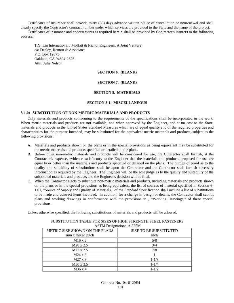
Contract No. 04-0120E4101
Certificates of insurance shall provide thirty (30) days advance written notice of cancellation or nonrenewal and shallclearly specify the Contractor's contract number under which services are provided to the State and the name of the project.
Certificates of insurance and endorsements as required herein shall be provided by Contractor's insurers to the followingaddress:
T.Y. Lin International / Moffatt & Nichol Engineers, A Joint Venturec/o Dealey, Renton & AssociatesP.O. Box 12675Oakland, CA 94604-2675Attn: Julie Nelson
SECTION 6. (BLANK)
SECTION 7. (BLANK)
SECTION 8. MATERIALS
SECTION 8-1. MISCELLANEOUS
8-1.01 SUBSTITUTION OF NON-METRIC MATERIALS AND PRODUCTSOnly materials and products conforming to the requirements of the specifications shall be incorporated in the work.
When metric materials and products are not available, and when approved by the Engineer, and at no cost to the State,materials and products in the United States Standard Measures which are of equal quality and of the required properties andcharacteristics for the purpose intended, may be substituted for the equivalent metric materials and products, subject to thefollowing provisions:
A. Materials and products shown on the plans or in the special provisions as being equivalent may be substituted forthe metric materials and products specified or detailed on the plans.
B. Before other non-metric materials and products will be considered for use, the Contractor shall furnish, at theContractor's expense, evidence satisfactory to the Engineer that the materials and products proposed for use areequal to or better than the materials and products specified or detailed on the plans. The burden of proof as to thequality and suitability of substitutions shall be upon the Contractor and the Contractor shall furnish necessaryinformation as required by the Engineer. The Engineer will be the sole judge as to the quality and suitability of thesubstituted materials and products and the Engineer's decision will be final.
C. When the Contractor elects to substitute non-metric materials and products, including materials and products shownon the plans or in the special provisions as being equivalent, the list of sources of material specified in Section 6-1.01, "Source of Supply and Quality of Materials," of the Standard Specification shall include a list of substitutionsto be made and contract items involved. In addition, for a change in design or details, the Contractor shall submitplans and working drawings in conformance with the provisions in , "Working Drawings," of these specialprovisions.
Unless otherwise specified, the following substitutions of materials and products will be allowed:
SUBSTITUTION TABLE FOR SIZES OF HIGH STRENGTH STEEL FASTENERS ASTM Designation: A 325M
METRIC SIZE SHOWN ON THE PLANSmm x thread pitch
SIZE TO BE SUBSTITUTEDinch
M16 x 2 5/8M20 x 2.5 3/4M22 x 2.5 7/8M24 x 3 1M27 x 3 1-1/8
M30 x 3.5 1-1/4M36 x 4 1-1/2
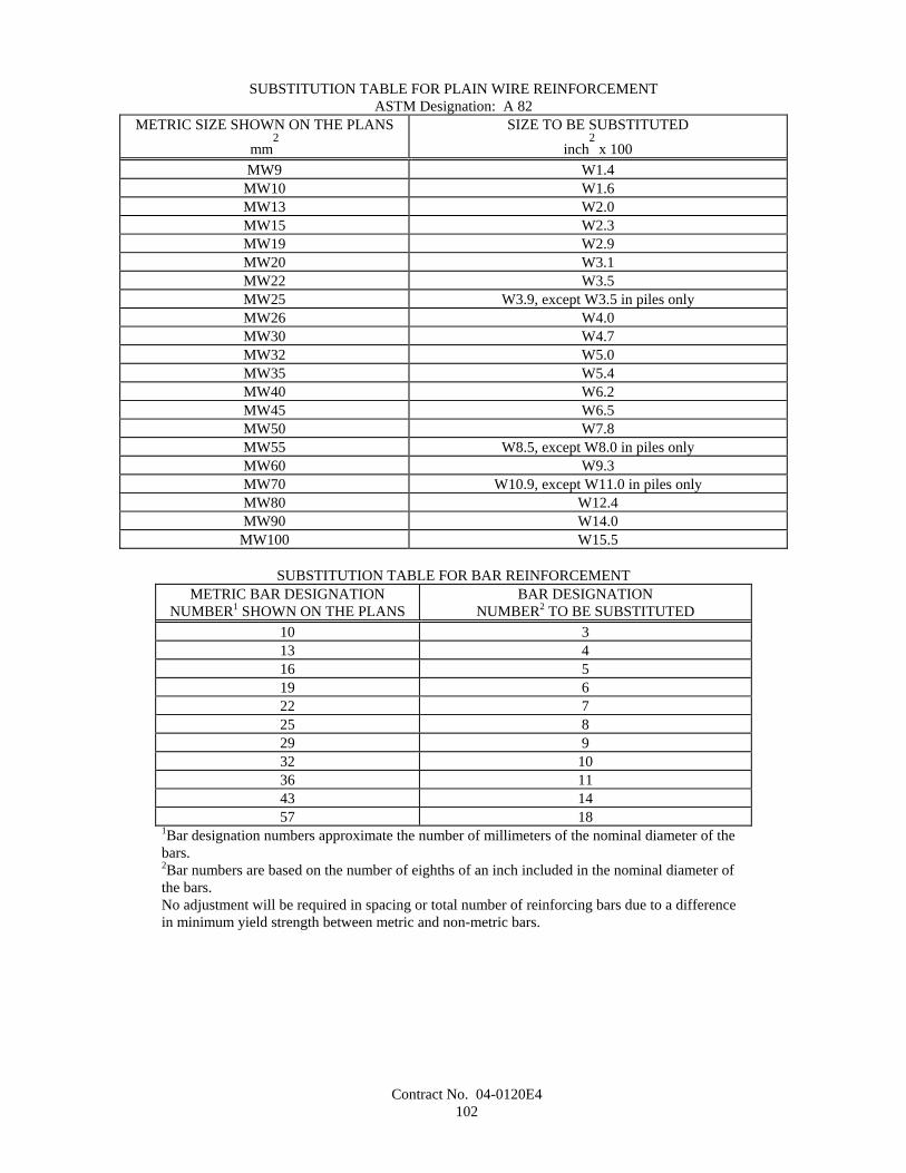
Contract No. 04-0120E4102
SUBSTITUTION TABLE FOR PLAIN WIRE REINFORCEMENTASTM Designation: A 82
METRIC SIZE SHOWN ON THE PLANS
mm2
SIZE TO BE SUBSTITUTED
inch2 x 100
MW9 W1.4MW10 W1.6MW13 W2.0MW15 W2.3MW19 W2.9MW20 W3.1MW22 W3.5MW25 W3.9, except W3.5 in piles onlyMW26 W4.0MW30 W4.7MW32 W5.0MW35 W5.4MW40 W6.2MW45 W6.5MW50 W7.8MW55 W8.5, except W8.0 in piles onlyMW60 W9.3MW70 W10.9, except W11.0 in piles onlyMW80 W12.4MW90 W14.0
MW100 W15.5
SUBSTITUTION TABLE FOR BAR REINFORCEMENTMETRIC BAR DESIGNATION
NUMBER1 SHOWN ON THE PLANSBAR DESIGNATION
NUMBER2 TO BE SUBSTITUTED10 313 416 519 622 725 829 932 1036 1143 1457 18
1Bar designation numbers approximate the number of millimeters of the nominal diameter of thebars.2Bar numbers are based on the number of eighths of an inch included in the nominal diameter ofthe bars.No adjustment will be required in spacing or total number of reinforcing bars due to a differencein minimum yield strength between metric and non-metric bars.
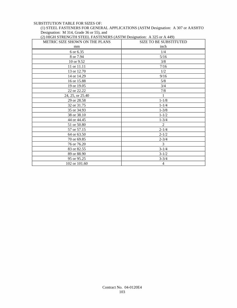
Contract No. 04-0120E4103
SUBSTITUTION TABLE FOR SIZES OF:(1) STEEL FASTENERS FOR GENERAL APPLICATIONS (ASTM Designation: A 307 or AASHTODesignation: M 314, Grade 36 or 55), and(2) HIGH STRENGTH STEEL FASTENERS (ASTM Designation: A 325 or A 449)
METRIC SIZE SHOWN ON THE PLANSmm
SIZE TO BE SUBSTITUTEDinch
6 or 6.35 1/48 or 7.94 5/16
10 or 9.52 3/811 or 11.11 7/1613 or 12.70 1/214 or 14.29 9/1616 or 15.88 5/819 or 19.05 3/422 or 22.22 7/8
24, 25, or 25.40 129 or 28.58 1-1/832 or 31.75 1-1/435 or 34.93 1-3/838 or 38.10 1-1/244 or 44.45 1-3/451 or 50.80 257 or 57.15 2-1/464 or 63.50 2-1/270 or 69.85 2-3/476 or 76.20 383 or 82.55 3-1/489 or 88.90 3-1/295 or 95.25 3-3/4
102 or 101.60 4
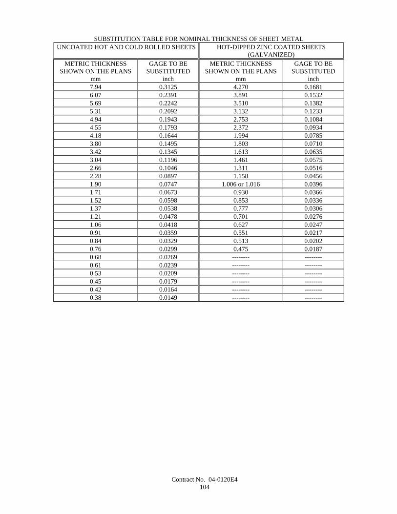
Contract No. 04-0120E4104
SUBSTITUTION TABLE FOR NOMINAL THICKNESS OF SHEET METALUNCOATED HOT AND COLD ROLLED SHEETS HOT-DIPPED ZINC COATED SHEETS
(GALVANIZED)METRIC THICKNESS
SHOWN ON THE PLANSmm
GAGE TO BESUBSTITUTED
inch
METRIC THICKNESSSHOWN ON THE PLANS
mm
GAGE TO BESUBSTITUTED
inch7.94 0.3125 4.270 0.16816.07 0.2391 3.891 0.15325.69 0.2242 3.510 0.13825.31 0.2092 3.132 0.12334.94 0.1943 2.753 0.10844.55 0.1793 2.372 0.09344.18 0.1644 1.994 0.07853.80 0.1495 1.803 0.07103.42 0.1345 1.613 0.06353.04 0.1196 1.461 0.05752.66 0.1046 1.311 0.05162.28 0.0897 1.158 0.04561.90 0.0747 1.006 or 1.016 0.03961.71 0.0673 0.930 0.03661.52 0.0598 0.853 0.03361.37 0.0538 0.777 0.03061.21 0.0478 0.701 0.02761.06 0.0418 0.627 0.02470.91 0.0359 0.551 0.02170.84 0.0329 0.513 0.02020.76 0.0299 0.475 0.01870.68 0.0269 -------- --------0.61 0.0239 -------- --------0.53 0.0209 -------- --------0.45 0.0179 -------- --------0.42 0.0164 -------- --------0.38 0.0149 -------- --------
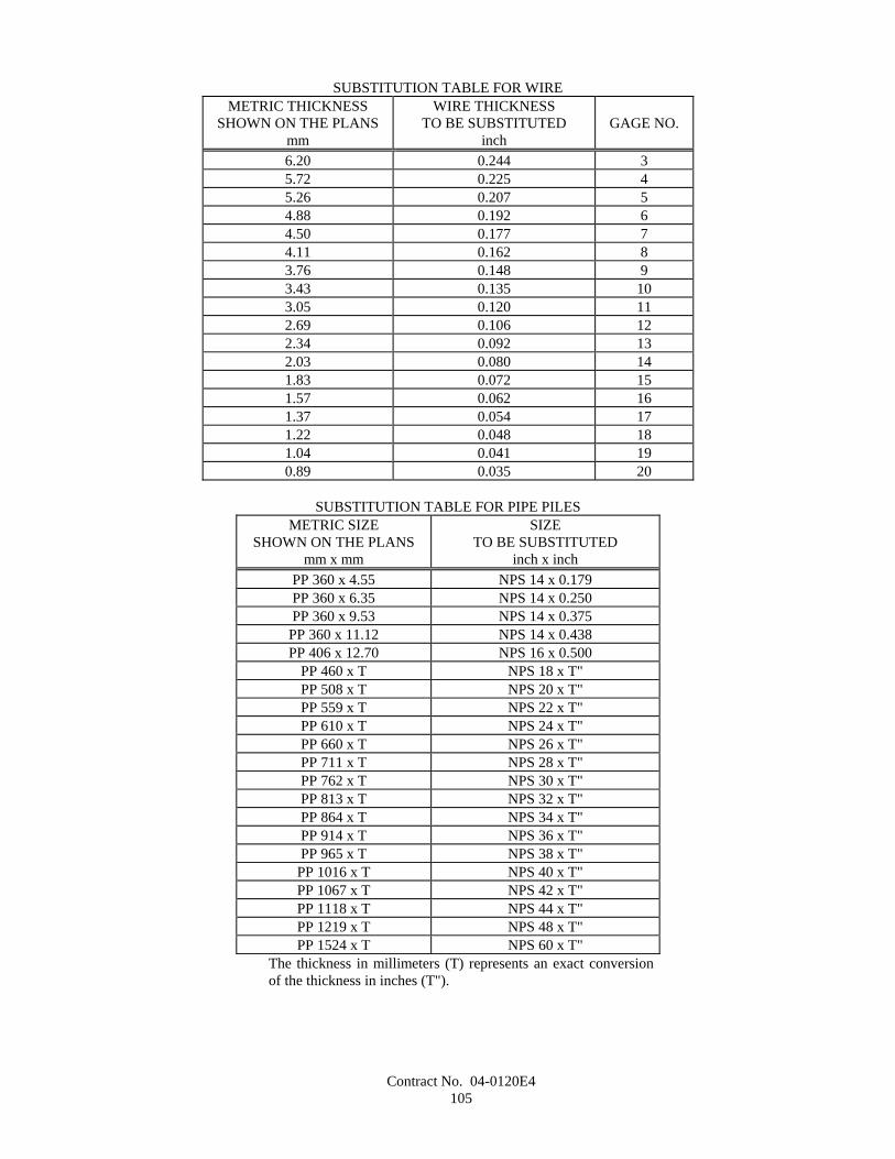
Contract No. 04-0120E4105
SUBSTITUTION TABLE FOR WIREMETRIC THICKNESS
SHOWN ON THE PLANSmm
WIRE THICKNESSTO BE SUBSTITUTED
inchGAGE NO.
6.20 0.244 35.72 0.225 45.26 0.207 54.88 0.192 64.50 0.177 74.11 0.162 83.76 0.148 93.43 0.135 103.05 0.120 112.69 0.106 122.34 0.092 132.03 0.080 141.83 0.072 151.57 0.062 161.37 0.054 171.22 0.048 181.04 0.041 190.89 0.035 20
SUBSTITUTION TABLE FOR PIPE PILESMETRIC SIZE
SHOWN ON THE PLANSmm x mm
SIZETO BE SUBSTITUTED
inch x inchPP 360 x 4.55 NPS 14 x 0.179PP 360 x 6.35 NPS 14 x 0.250PP 360 x 9.53 NPS 14 x 0.375
PP 360 x 11.12 NPS 14 x 0.438PP 406 x 12.70 NPS 16 x 0.500
PP 460 x T NPS 18 x T"PP 508 x T NPS 20 x T"PP 559 x T NPS 22 x T"PP 610 x T NPS 24 x T"PP 660 x T NPS 26 x T"PP 711 x T NPS 28 x T"PP 762 x T NPS 30 x T"PP 813 x T NPS 32 x T"PP 864 x T NPS 34 x T"PP 914 x T NPS 36 x T"PP 965 x T NPS 38 x T"
PP 1016 x T NPS 40 x T"PP 1067 x T NPS 42 x T"PP 1118 x T NPS 44 x T"PP 1219 x T NPS 48 x T"PP 1524 x T NPS 60 x T"
The thickness in millimeters (T) represents an exact conversionof the thickness in inches (T").
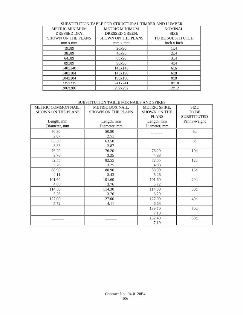
Contract No. 04-0120E4106
SUBSTITUTION TABLE FOR STRUCTURAL TIMBER AND LUMBERMETRIC MINIMUM
DRESSED DRY,SHOWN ON THE PLANS
mm x mm
METRIC MINIMUMDRESSED GREEN,
SHOWN ON THE PLANSmm x mm
NOMINALSIZE
TO BE SUBSTITUTEDinch x inch
19x89 20x90 1x438x89 40x90 2x464x89 65x90 3x489x89 90x90 4x4
140x140 143x143 6x6140x184 143x190 6x8184x184 190x190 8x8235x235 241x241 10x10286x286 292x292 12x12
SUBSTITUTION TABLE FOR NAILS AND SPIKESMETRIC COMMON NAIL,SHOWN ON THE PLANS
Length, mmDiameter, mm
METRIC BOX NAIL,SHOWN ON THE PLANS
Length, mmDiameter, mm
METRIC SPIKE,SHOWN ON THE
PLANSLength, mm
Diameter, mm
SIZETO BE
SUBSTITUTEDPenny-weight
50.802.87
50.802.51
______ 6d
63.503.33
63.502.87
______ 8d
76.203.76
76.203.25
76.204.88
10d
82.553.76
82.553.25
82.554.88
12d
88.904.11
88.903.43
88.905.26
16d
101.604.88
101.603.76
101.605.72
20d
114.305.26
114.303.76
114.306.20
30d
127.005.72
127.004.11
127.006.68
40d
______ ______ 139.707.19
50d
______ ______ 152.407.19
60d
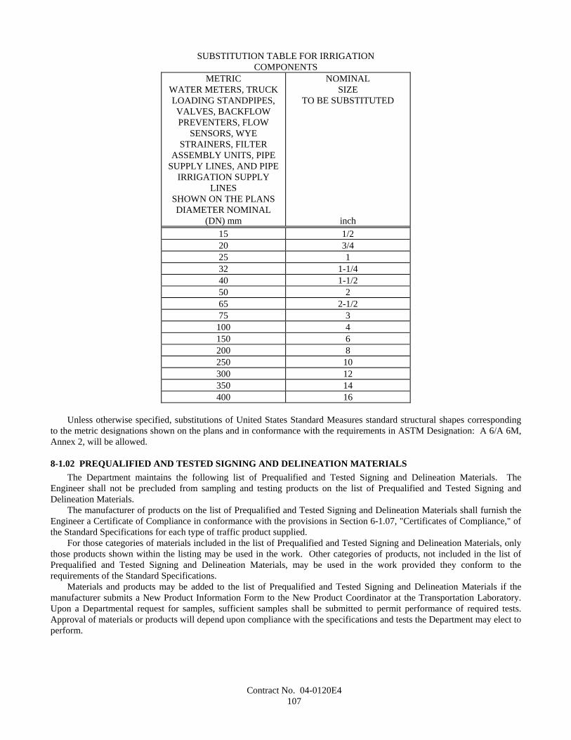
Contract No. 04-0120E4107
SUBSTITUTION TABLE FOR IRRIGATIONCOMPONENTS
METRICWATER METERS, TRUCKLOADING STANDPIPES,VALVES, BACKFLOWPREVENTERS, FLOW
SENSORS, WYESTRAINERS, FILTER
ASSEMBLY UNITS, PIPESUPPLY LINES, AND PIPE
IRRIGATION SUPPLYLINES
SHOWN ON THE PLANSDIAMETER NOMINAL
(DN) mm
NOMINALSIZE
TO BE SUBSTITUTED
inch15 1/220 3/425 132 1-1/440 1-1/250 265 2-1/275 3
100 4150 6200 8250 10300 12350 14400 16
Unless otherwise specified, substitutions of United States Standard Measures standard structural shapes correspondingto the metric designations shown on the plans and in conformance with the requirements in ASTM Designation: A 6/A 6M,Annex 2, will be allowed.
8-1.02 PREQUALIFIED AND TESTED SIGNING AND DELINEATION MATERIALSThe Department maintains the following list of Prequalified and Tested Signing and Delineation Materials. The
Engineer shall not be precluded from sampling and testing products on the list of Prequalified and Tested Signing andDelineation Materials.
The manufacturer of products on the list of Prequalified and Tested Signing and Delineation Materials shall furnish theEngineer a Certificate of Compliance in conformance with the provisions in Section 6-1.07, "Certificates of Compliance," ofthe Standard Specifications for each type of traffic product supplied.
For those categories of materials included in the list of Prequalified and Tested Signing and Delineation Materials, onlythose products shown within the listing may be used in the work. Other categories of products, not included in the list ofPrequalified and Tested Signing and Delineation Materials, may be used in the work provided they conform to therequirements of the Standard Specifications.
Materials and products may be added to the list of Prequalified and Tested Signing and Delineation Materials if themanufacturer submits a New Product Information Form to the New Product Coordinator at the Transportation Laboratory.Upon a Departmental request for samples, sufficient samples shall be submitted to permit performance of required tests.Approval of materials or products will depend upon compliance with the specifications and tests the Department may elect toperform.
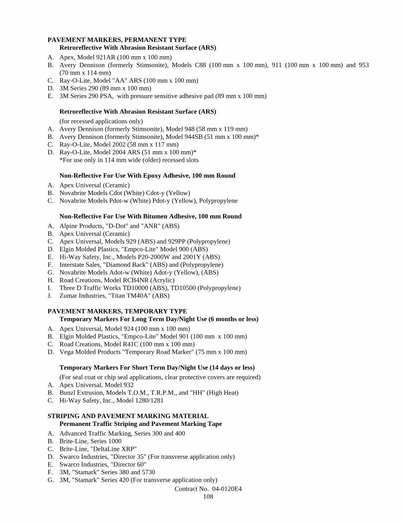
Contract No. 04-0120E4108
PAVEMENT MARKERS, PERMANENT TYPERetroreflective With Abrasion Resistant Surface (ARS)
A. Apex, Model 921AR (100 mm x 100 mm)B. Avery Dennison (formerly Stimsonite), Models C88 (100 mm x 100 mm), 911 (100 mm x 100 mm) and 953
(70 mm x 114 mm)C. Ray-O-Lite, Model "AA" ARS (100 mm x 100 mm)D. 3M Series 290 (89 mm x 100 mm)E. 3M Series 290 PSA, with pressure sensitive adhesive pad (89 mm x 100 mm)
Retroreflective With Abrasion Resistant Surface (ARS)(for recessed applications only)
A. Avery Dennison (formerly Stimsonite), Model 948 (58 mm x 119 mm)B. Avery Dennison (formerly Stimsonite), Model 944SB (51 mm x 100 mm)*C. Ray-O-Lite, Model 2002 (58 mm x 117 mm)D. Ray-O-Lite, Model 2004 ARS (51 mm x 100 mm)*
*For use only in 114 mm wide (older) recessed slots
Non-Reflective For Use With Epoxy Adhesive, 100 mm RoundA. Apex Universal (Ceramic)B. Novabrite Models Cdot (White) Cdot-y (Yellow)C. Novabrite Models Pdot-w (White) Pdot-y (Yellow), Polypropylene
Non-Reflective For Use With Bitumen Adhesive, 100 mm RoundA. Alpine Products, "D-Dot" and "ANR" (ABS)B. Apex Universal (Ceramic)C. Apex Universal, Models 929 (ABS) and 929PP (Polypropylene)D. Elgin Molded Plastics, "Empco-Lite" Model 900 (ABS)E. Hi-Way Safety, Inc., Models P20-2000W and 2001Y (ABS)F. Interstate Sales, "Diamond Back" (ABS) and (Polypropylene)G. Novabrite Models Adot-w (White) Adot-y (Yellow), (ABS)H. Road Creations, Model RCB4NR (Acrylic)I. Three D Traffic Works TD10000 (ABS), TD10500 (Polypropylene)J. Zumar Industries, "Titan TM40A" (ABS)
PAVEMENT MARKERS, TEMPORARY TYPETemporary Markers For Long Term Day/Night Use (6 months or less)
A. Apex Universal, Model 924 (100 mm x 100 mm)B. Elgin Molded Plastics, "Empco-Lite" Model 901 (100 mm x 100 mm)C. Road Creations, Model R41C (100 mm x 100 mm)D. Vega Molded Products "Temporary Road Marker" (75 mm x 100 mm)
Temporary Markers For Short Term Day/Night Use (14 days or less)(For seal coat or chip seal applications, clear protective covers are required)
A. Apex Universal, Model 932B. Bunzl Extrusion, Models T.O.M., T.R.P.M., and "HH" (High Heat)C. Hi-Way Safety, Inc., Model 1280/1281
STRIPING AND PAVEMENT MARKING MATERIALPermanent Traffic Striping and Pavement Marking Tape
A. Advanced Traffic Marking, Series 300 and 400B. Brite-Line, Series 1000C. Brite-Line, "DeltaLine XRP"D. Swarco Industries, "Director 35" (For transverse application only)E. Swarco Industries, "Director 60"F. 3M, "Stamark" Series 380 and 5730G. 3M, "Stamark" Series 420 (For transverse application only)
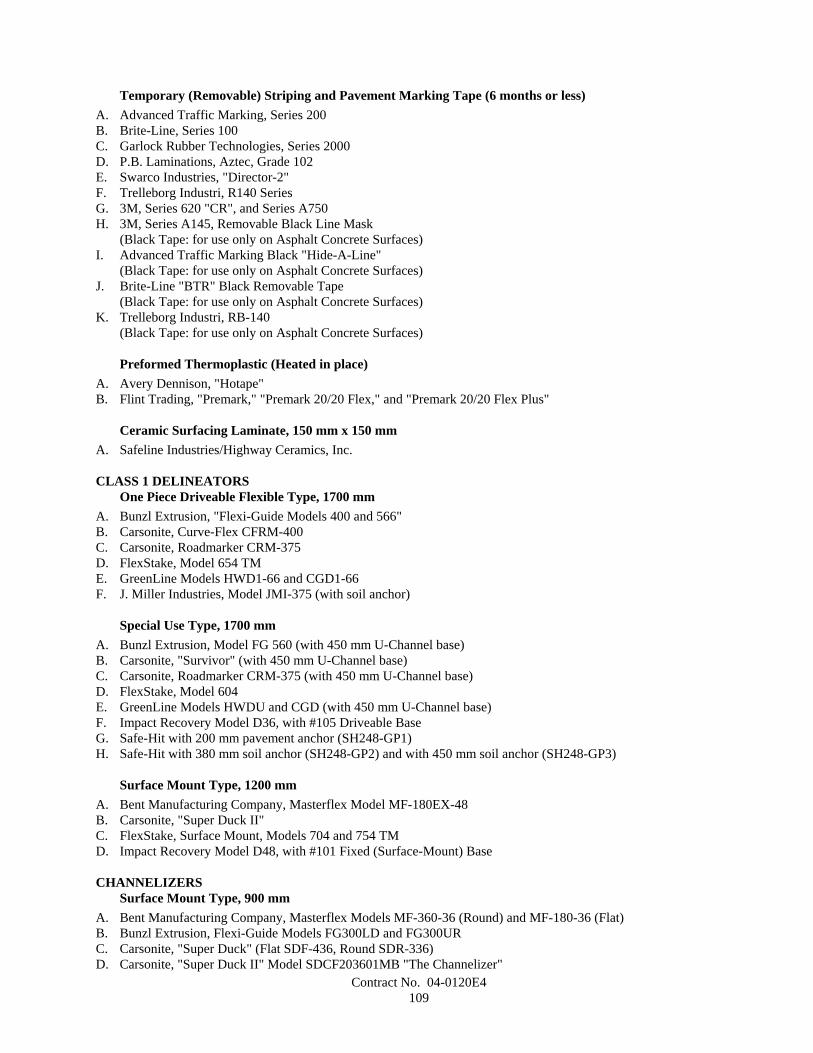
Contract No. 04-0120E4109
Temporary (Removable) Striping and Pavement Marking Tape (6 months or less)A. Advanced Traffic Marking, Series 200B. Brite-Line, Series 100C. Garlock Rubber Technologies, Series 2000D. P.B. Laminations, Aztec, Grade 102E. Swarco Industries, "Director-2"F. Trelleborg Industri, R140 SeriesG. 3M, Series 620 "CR", and Series A750H. 3M, Series A145, Removable Black Line Mask
(Black Tape: for use only on Asphalt Concrete Surfaces)I. Advanced Traffic Marking Black "Hide-A-Line"
(Black Tape: for use only on Asphalt Concrete Surfaces)J. Brite-Line "BTR" Black Removable Tape
(Black Tape: for use only on Asphalt Concrete Surfaces)K. Trelleborg Industri, RB-140
(Black Tape: for use only on Asphalt Concrete Surfaces)
Preformed Thermoplastic (Heated in place)A. Avery Dennison, "Hotape"B. Flint Trading, "Premark," "Premark 20/20 Flex," and "Premark 20/20 Flex Plus"
Ceramic Surfacing Laminate, 150 mm x 150 mmA. Safeline Industries/Highway Ceramics, Inc.
CLASS 1 DELINEATORSOne Piece Driveable Flexible Type, 1700 mm
A. Bunzl Extrusion, "Flexi-Guide Models 400 and 566"B. Carsonite, Curve-Flex CFRM-400C. Carsonite, Roadmarker CRM-375D. FlexStake, Model 654 TME. GreenLine Models HWD1-66 and CGD1-66F. J. Miller Industries, Model JMI-375 (with soil anchor)
Special Use Type, 1700 mmA. Bunzl Extrusion, Model FG 560 (with 450 mm U-Channel base)B. Carsonite, "Survivor" (with 450 mm U-Channel base)C. Carsonite, Roadmarker CRM-375 (with 450 mm U-Channel base)D. FlexStake, Model 604E. GreenLine Models HWDU and CGD (with 450 mm U-Channel base)F. Impact Recovery Model D36, with #105 Driveable BaseG. Safe-Hit with 200 mm pavement anchor (SH248-GP1)H. Safe-Hit with 380 mm soil anchor (SH248-GP2) and with 450 mm soil anchor (SH248-GP3)
Surface Mount Type, 1200 mmA. Bent Manufacturing Company, Masterflex Model MF-180EX-48B. Carsonite, "Super Duck II"C. FlexStake, Surface Mount, Models 704 and 754 TMD. Impact Recovery Model D48, with #101 Fixed (Surface-Mount) Base
CHANNELIZERSSurface Mount Type, 900 mm
A. Bent Manufacturing Company, Masterflex Models MF-360-36 (Round) and MF-180-36 (Flat)B. Bunzl Extrusion, Flexi-Guide Models FG300LD and FG300URC. Carsonite, "Super Duck" (Flat SDF-436, Round SDR-336)D. Carsonite, "Super Duck II" Model SDCF203601MB "The Channelizer"
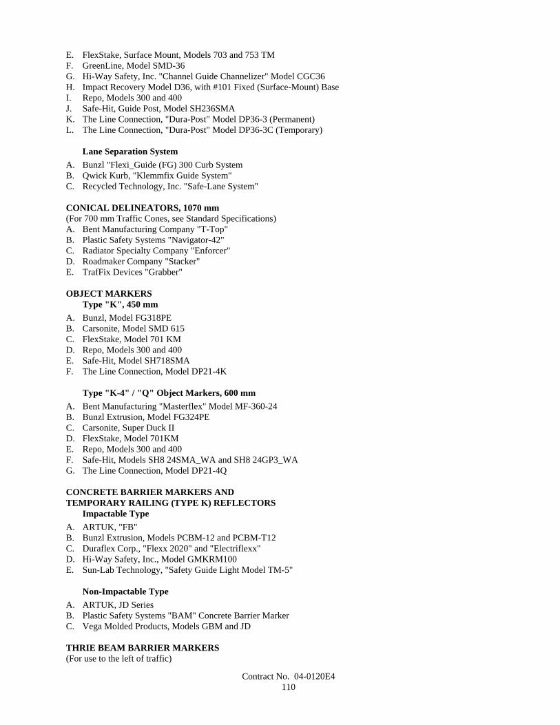
Contract No. 04-0120E4110
E. FlexStake, Surface Mount, Models 703 and 753 TMF. GreenLine, Model SMD-36G. Hi-Way Safety, Inc. "Channel Guide Channelizer" Model CGC36H. Impact Recovery Model D36, with #101 Fixed (Surface-Mount) BaseI. Repo, Models 300 and 400J. Safe-Hit, Guide Post, Model SH236SMAK. The Line Connection, "Dura-Post" Model DP36-3 (Permanent)L. The Line Connection, "Dura-Post" Model DP36-3C (Temporary)
Lane Separation SystemA. Bunzl "Flexi_Guide (FG) 300 Curb SystemB. Qwick Kurb, "Klemmfix Guide System"C. Recycled Technology, Inc. "Safe-Lane System"
CONICAL DELINEATORS, 1070 mm(For 700 mm Traffic Cones, see Standard Specifications)A. Bent Manufacturing Company "T-Top"B. Plastic Safety Systems "Navigator-42"C. Radiator Specialty Company "Enforcer"D. Roadmaker Company "Stacker"E. TrafFix Devices "Grabber"
OBJECT MARKERSType "K", 450 mm
A. Bunzl, Model FG318PEB. Carsonite, Model SMD 615C. FlexStake, Model 701 KMD. Repo, Models 300 and 400E. Safe-Hit, Model SH718SMAF. The Line Connection, Model DP21-4K
Type "K-4" / "Q" Object Markers, 600 mmA. Bent Manufacturing "Masterflex" Model MF-360-24B. Bunzl Extrusion, Model FG324PEC. Carsonite, Super Duck IID. FlexStake, Model 701KME. Repo, Models 300 and 400F. Safe-Hit, Models SH8 24SMA_WA and SH8 24GP3_WAG. The Line Connection, Model DP21-4Q
CONCRETE BARRIER MARKERS ANDTEMPORARY RAILING (TYPE K) REFLECTORS
Impactable TypeA. ARTUK, "FB"B. Bunzl Extrusion, Models PCBM-12 and PCBM-T12C. Duraflex Corp., "Flexx 2020" and "Electriflexx"D. Hi-Way Safety, Inc., Model GMKRM100E. Sun-Lab Technology, "Safety Guide Light Model TM-5"
Non-Impactable TypeA. ARTUK, JD SeriesB. Plastic Safety Systems "BAM" Concrete Barrier MarkerC. Vega Molded Products, Models GBM and JD
THRIE BEAM BARRIER MARKERS(For use to the left of traffic)
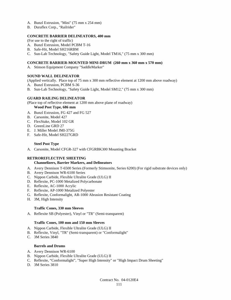
Contract No. 04-0120E4111
A. Bunzl Extrusion, "Mini" (75 mm x 254 mm)B. Duraflex Corp., "Railrider"
CONCRETE BARRIER DELINEATORS, 400 mm(For use to the right of traffic)A. Bunzl Extrusion, Model PCBM T-16B. Safe-Hit, Model SH216RBMC. Sun-Lab Technology, "Safety Guide Light, Model TM16," (75 mm x 300 mm)
CONCRETE BARRIER-MOUNTED MINI-DRUM (260 mm x 360 mm x 570 mm)A. Stinson Equipment Company "SaddleMarker"
SOUND WALL DELINEATOR(Applied vertically. Place top of 75 mm x 300 mm reflective element at 1200 mm above roadway)A. Bunzl Extrusion, PCBM S-36B. Sun-Lab Technology, "Safety Guide Light, Model SM12," (75 mm x 300 mm)
GUARD RAILING DELINEATOR(Place top of reflective element at 1200 mm above plane of roadway)
Wood Post Type, 686 mmA. Bunzl Extrusion, FG 427 and FG 527B. Carsonite, Model 427C. FlexStake, Model 102 GRD. GreenLine GRD 27E. J. Miller Model JMI-375GF. Safe-Hit, Model SH227GRD
Steel Post TypeA. Carsonite, Model CFGR-327 with CFGRBK300 Mounting Bracket
RETROREFLECTIVE SHEETINGChannelizers, Barrier Markers, and Delineators
A. Avery Dennison T-6500 Series (Formerly Stimsonite, Series 6200) (For rigid substrate devices only)B. Avery Dennison WR-6100 SeriesC. Nippon Carbide, Flexible Ultralite Grade (ULG) IID. Reflexite, PC-1000 Metalized PolycarbonateE. Reflexite, AC-1000 AcrylicF. Reflexite, AP-1000 Metalized PolyesterG. Reflexite, Conformalight, AR-1000 Abrasion Resistant CoatingH. 3M, High Intensity
Traffic Cones, 330 mm SleevesA. Reflexite SB (Polyester), Vinyl or "TR" (Semi-transparent)
Traffic Cones, 100 mm and 150 mm SleevesA. Nippon Carbide, Flexible Ultralite Grade (ULG) IIB. Reflexite, Vinyl, "TR" (Semi-transparent) or "Conformalight"C. 3M Series 3840
Barrels and DrumsA. Avery Dennison WR-6100B. Nippon Carbide, Flexible Ultralite Grade (ULG) IIC. Reflexite, “Conformalight”, "Super High Intensity" or "High Impact Drum Sheeting"D. 3M Series 3810

Contract No. 04-0120E4112
Barricades: Type I, Medium-Intensity (Typically Enclosed Lens, Glass-Bead Element)A. American Decal, AdcoliteB. Avery Dennison, T-1500 and T-1600 seriesC. 3M Engineer Grade, Series 3170
Barricades: Type II, Medium-High-Intensity (Typically Enclosed Lens, Glass-Bead Element)A. Avery Dennison, T-2500 SeriesB. Kiwalite Type IIC. Nikkalite 1800 Series
Signs: Type II, Medium-High-Intensity (Typically Enclosed Lens, Glass-Bead Element)A. Avery Dennison, T-2500 SeriesB. Kiwalite, Type IIC. Nikkalite 1800 Series
Signs: Type III, High-Intensity (Typically Encapsulated Glass-Bead Element)A. Avery Dennison, T-5500 SeriesB. Nippon Carbide, Nikkalite Brand Ultralite Grade IIC. 3M Series 3870
Signs: Type IV, High-Intensity (Typically Unmetallized Microprismatic Element)A. Avery Dennison, T-6500 Series (Formerly Stimsonite Series 6200)B. Nippon Carbide, Crystal Grade, 94000 Series
Signs: Type VI, Elastomeric (Roll-Up) High-Intensity, without AdhesiveA. Avery Dennison, WU-6014 (Fluorescent orange)B. Reflexite "Vinyl" (Orange)C. Reflexite "SuperBright" (Fluorescent orange)D. Reflexite "Marathon" (Fluorescent orange)E. 3M Series RS34 (Orange) and RS20 (Fluorescent orange)
Signs: Type VII, Super-High-Intensity (Typically Unmetallized Microprismatic Element)A. 3M LDP Series 3970
Signs: Type VIII, Super-High-Intensity (Typically Unmetallized Microprismatic Element)A. Avery Dennison, T-7500 Series
Signs: Type IX, Very-High-Intensity (Typically Unmetallized Microprismatic Element)A. 3M VIP Series 3990 Diamond Grade
SPECIALTY SIGNSA. All Sign Products, STOP Sign (All Plastic), 750 mmB. Relexite "Endurance" Work Zone Sign (with Semi-Rigid Plastic Substrate)
SIGN SUBSTRATEFiberglass Reinforced Plastic (FRP)
A. Fiber-BriteB. Sequentia, "Polyplate"C. Inteplast Group "InteCel" (13 mm for Post-Mounted CZ Signs, 1200 mm or less)
SECTION 8-2. CONCRETE
8-2.01 PORTLAND CEMENT CONCRETEPortland cement concrete shall conform to the provisions in Section 90, "Portland Cement Concrete," of the Standard
Specifications and these special provisions.
Contract No. 04-0120E4113
References to Section 90-2.01, "Portland Cement," of the Standard Specifications shall mean Section 90-2.01, "Cement,"of the Standard Specifications.
Mineral admixture shall be combined with cement in conformance with the provisions in Section 90-4.08, "RequiredUse of Mineral Admixtures," of the Standard Specifications for the concrete materials specified in Section 56-2, "RoadsideSigns," of the Standard Specifications.
The requirements of Section 90-4.08, "Required Use of Mineral Admixture," of the Standard Specifications shall notapply to Section 19-3.025C, "Soil Cement Bedding," of the Standard Specifications.
The Department maintains a list of sources of fine and coarse aggregate that have been approved for use with a reducedamount of mineral admixture in the total amount of cementitious material to be used. A source of aggregate will beconsidered for addition to the approved list if the producer of the aggregate submits to the Transportation Laboratorycertified test results from a qualified testing laboratory that verify the aggregate complies with the requirements. Prior tostarting the testing, the aggregate test shall be registered with the Department. A registration number can be obtained bycalling (916) 227-7228. The registration number shall be used as the identification for the aggregate sample incorrespondence with the Department. Upon request, a split of the tested sample shall be provided to the Department.Approval of aggregate will depend upon compliance with the specifications, based on the certified test results submitted,together with any replicate testing the Department may elect to perform. Approval will expire 3 years from the date the mostrecent registered and evaluated sample was collected from the aggregate source.
Qualified testing laboratories shall conform to the following requirements:
A. Laboratories performing ASTM Designation: C 1293 shall participate in the Cement and Concrete ReferenceLaboratory (CCRL) Concrete Proficiency Sample Program and shall have received a score of 3 or better on all testsof the previous 2 sets of concrete samples.
B. Laboratories performing ASTM Designation: C 1260 shall participate in the Cement and Concrete ReferenceLaboratory (CCRL) Pozzolan Proficiency Sample Program and shall have received a score of 3 or better on theshrinkage and soundness tests of the previous 2 sets of pozzolan samples.
Aggregates on the list shall conform to one of the following requirements:
A. When the aggregate is tested in conformance with the requirements in California Test 554 and ASTM Designation:C 1293, the average expansion at one year shall be less than or equal to 0.040 percent; or
B. When the aggregate is tested in conformance with the requirements in California Test 554 and ASTM Designation:C 1260, the average of the expansion at 16 days shall be less than or equal to 0.15 percent.
The amounts of cement and mineral admixture used in cementitious material shall be sufficient to satisfy the minimumcementitious material content requirements specified in Section 90-1.01, "Description," or Section 90-4.05, "Optional Use ofChemical Admixtures," of the Standard Specifications and shall conform to the following:
A. The minimum amount of cement shall not be less than 75 percent by mass of the specified minimum cementitiousmaterial content.
B. The minimum amount of mineral admixture to be combined with cement shall be determined using one of thefollowing criteria:
1. When the calcium oxide content of a mineral admixture is equal to or less than 2 percent by mass, the amountof mineral admixture shall not be less than 15 percent by mass of the total amount of cementitious material tobe used in the mix.
2. When the calcium oxide content of a mineral admixture is greater than 2 percent by mass, and any of theaggregates used are not listed on the approved list as specified in these special provisions, then the amount ofmineral admixture shall not be less than 25 percent by mass of the total amount of cementitious material to beused in the mix.
3. When the calcium oxide content of a mineral admixture is greater than 2 percent by mass and the fine andcoarse aggregates are listed on the approved list as specified in these special provisions, then the amount ofmineral admixture shall not be less than 15 percent by mass of the total amount of cementitious material to beused in the mix.
4. When a mineral admixture that conforms to the provisions for silica fume in Section 90-2.04, "AdmixtureMaterials," of the Standard Specifications is used, the amount of mineral admixture shall not be less than10 percent by mass of the total amount of cementitious material to be used in the mix.
5. When a mineral admixture that conforms to the provisions for silica fume in Section 90-2.04, "AdmixtureMaterials," of the Standard Specifications is used and the fine and coarse aggregates are listed on the approved
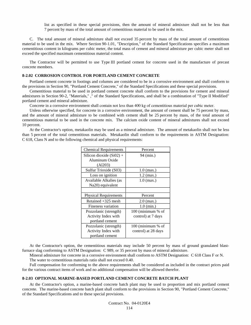
Contract No. 04-0120E4114
list as specified in these special provisions, then the amount of mineral admixture shall not be less than7 percent by mass of the total amount of cementitious material to be used in the mix.
C. The total amount of mineral admixture shall not exceed 35 percent by mass of the total amount of cementitiousmaterial to be used in the mix. Where Section 90-1.01, "Description," of the Standard Specifications specifies a maximumcementitious content in kilograms per cubic meter, the total mass of cement and mineral admixture per cubic meter shall notexceed the specified maximum cementitious material content.
The Contractor will be permitted to use Type III portland cement for concrete used in the manufacture of precastconcrete members.
8-2.02 CORROSION CONTROL FOR PORTLAND CEMENT CONCRETEPortland cement concrete in footings and columns are considered to be in a corrosive environment and shall conform to
the provisions in Section 90, "Portland Cement Concrete," of the Standard Specifications and these special provisions.Cementitious material to be used in portland cement concrete shall conform to the provisions for cement and mineral
admixtures in Section 90-2, "Materials," ," of the Standard Specifications, and shall be a combination of "Type II Modified"portland cement and mineral admixture.
Concrete in a corrosive environment shall contain not less than 400 kg of cementitious material per cubic meter.Unless otherwise specified, for concrete in a corrosive environment, the amount of cement shall be 75 percent by mass,
and the amount of mineral admixture to be combined with cement shall be 25 percent by mass, of the total amount ofcementitious material to be used in the concrete mix. The calcium oxide content of mineral admixtures shall not exceed10 percent.
At the Contractor's option, metakaolin may be used as a mineral admixture. The amount of metakaolin shall not be lessthan 5 percent of the total cementitious materials. Metakaolin shall conform to the requirements in ASTM Designation:C 618, Class N and to the following chemical and physical requirements:
Chemical Requirements PercentSilicon dioxide (Si02) +
Aluminum Oxide(Al203)
94 (min.)
Sulfur Trioxide (S03) 1.0 (max.)Loss on ignition 1.2 (max.)
Available Alkalies (asNa20) equivalent
1.0 (max.)
Physical Requirements PercentRetained +325 mesh 2.0 (max.)Fineness variation 1.0 (min.)
Pozzolanic (strength)Activity Index with
portland cement
100 (minimum % ofcontrol) at 7 days
Pozzolanic (strength)Activity Index with
portland cement
100 (minimum % ofcontrol) at 28 days
At the Contractor's option, the cementitious materials may include 50 percent by mass of ground granulated blast-furnace slag conforming to ASTM Designation: C 989, or 35 percent by mass of mineral admixture.
Mineral admixture for concrete in a corrosive environment shall conform to ASTM Designation: C 618 Class F or N.The water to cementitious materials ratio shall not exceed 0.40.Full compensation for conforming to the above requirements shall be considered as included in the contract prices paid
for the various contract items of work and no additional compensation will be allowed therefor.
8-2.03 OPTIONAL MARINE-BASED PORTLAND CEMENT CONCRETE BATCH PLANTAt the Contractor's option, a marine-based concrete batch plant may be used to proportion and mix portland cement
concrete. The marine-based concrete batch plant shall conform to the provisions in Section 90, "Portland Cement Concrete,"of the Standard Specifications and to these special provisions.
Contract No. 04-0120E4115
The Contractor shall obtaining and comply with all required permits, clearances, and approvals to operate a marine-based concrete batch plant, including transport of materials to and from the batch plant and disposal of all waste productsgenerated by the batch plant. Permitting agencies with jurisdictional responsibilities for the marine-based concrete batchplant include, but are not limited to the U.S. Corps of Engineers, U.S. Coast Guard, San Francisco Bay Regional WaterQuality Control Board , San Francisco Bay Conservation and Development Commission and the Bay Area Air QualityManagement District. Delays in obtaining permits, clearances, and approvals will not be reason for granting an extension ofcontract time.
The requirement for providing portland cement concrete undersupports for scale bearing points as specified in Section9-1.01, "Measurement of Quantities," of the Standard Specifications shall not apply.
The Contractor shall submit, in writing, an operations plan for the marine-based plant to the Engineer at least 30 daysprior to performing a prequalification batch test. The plan shall include:
A. a detailed description of the batch plant;B. the navigational and operational requirements for the batch plant under all expected environmental conditions;C. the planned movements of the batch plant, the anchoring and berthing locations of the plant, and the frequency and
extent of all necessary relocations;D. the limiting conditions for operation and the production capacity under which the batch plant can safely operate and
produce portland cement concrete in compliance with these specifications;E. the limitations of the weighing equipment to function accurately under shifting and unleveled conditions caused by
wind and wave actions;F. scale accuracy, tolerances and variations expected from shifting and tilting due to wave action; andG. methods or devices, such as visual and/or audio signals, which will be utilized to notify plant operators that the
tolerances of these specifications have been exceeded.
A prequalification batch test shall be performed at least 60 days prior to the production of the first concrete batched bythe plant for use in the project. The prequalification batch test shall demonstrate the plant is capable of proportioning andmixing concrete in conformance with these special provisions and under the typical marine conditions which will beencountered during the project. This test shall include a production minimum of four batches. Each batch size shall be aminimum of eight cubic meters or otherwise as approved by the Engineer. These batches shall be produced at locationswithin the project limits, or as approved by the Engineer. The four batch test produced shall be transported and weighed at aland based certified scales in accordance with the requirements of Section 9-1.01, Measurement and Quantities," of theStandard Specifications. The total weight from the batch plant weigh tickets for each of the batches measured on the floatingbatch plant shall be within 2% of the weight measured by the land based certified scales. If the total weight varies more than2% , the Contractor shall revise the operation plan and perform another prequalification test until the total measured weightis within 2% of the total batch plant weight tickets. Failure to comply with this requirement will be grounds for theEngineer rejecting the use of the batch plant for producing concrete for the contract.
At the discretion of the Engineer, the Contractor shall perform the prequalification batch test again if the Contractorsignificantly changes equipment or if problems are detected in the normal operation of the marine based portland cementconcrete batch plant.
After completion of the prequalification batch test, the concrete produced during the test shall become the property ofthe Contractor, and all materials shall be disposed of in conformance with the provisions in Section 7-1.13, "Disposal ofMaterial Outside the Highway Right of Way," of the Standard Specifications.
A container, capable of holding at least 2.25 cubic meters, shall be available at the batch plant at all times. Thecontainer shall be either a cylindrical or of a rectilinear shape. It shall be mortar tight and rigid and its walls shall not deflectmore than 1 millimeter (mm) during the placing of concrete. The diameter of the base of the cylinder container shall bebetween 1000 mm and 1250 mm. The dimensions of the width and length of the rectilinear container shall be between 900mm and 1000 mm. During production and when ordered by the Engineer, the accuracy of the concrete batching shall bechecked against this volumetric measure of two cubic meters. The Contractor, using calibrated measures on the MarineBased Portland Cement Concrete Batch Plant, shall prepare a test batch of two cubic meters. The test batch shall be pouredinto the measuring device, at which time, the measured volume shall be determined by multiplying the height of the concretebatch in the measuring device by the area of the base of the measuring device. The measured volume shall be within 2% ofthe volume calculated from the weigh batch tickets.
In addition, commercial class test masses, at least 25% of the total optional batch plant scale capacity shall be availableat all times for use of testing the scales during production. The test masses shall be required by California Test 109. Theplant scales shall be subjected to operation and scale tolerances testing in all weather.
Facilities on the premises of the floating batch plant shall provided to the Engineer for performing all necessarysampling and testing, including space for safe storage of test samples and testing equipment. For sampling purposes, a

Contract No. 04-0120E4116
method of diverting the freshly mixed concrete between the mixer and the delivery system shall be provided. The samplingand testing facilities on the premises shall be approved by the Engineer.
The Aggregates shall be protected from exposure to salt waters. Coarse aggregate may be proportioned by volume.Containers, bags, or other packages of pre-weighed cementitious material if used shall be sealed and moisture proof. TheContainers, bags, or packages shall be tagged showing exact weight, date and time of batching, and source of cementitiousmaterial. The tags shall be numbered serially. The tag number in addition to the weight of the material shall be included oneach batch certificate used incorporating pre-weighed non-bulk material.
Full compensation for operating a floating batch plant, in accordance with the requirements of all permitting agencies,batching materials, disposing of materials, developing and submitting and operations plan, performing prequalification batchtests, periodic weight and volume checks, providing sampling and testing facilities and necessary corrective actions required,including recertification of the batch plant shall be considered as included in the contract prices paid for various items ofwork involved and no additional compensation will be allowed therefor.
SECTION 8-3. WELDING8-3.01 WELDING
GENERALFlux core welding electrodes conforming to the requirements of AWS A5.20 E6XT-4 or E7XT-4 shall not be used to
perform welding for this project.Wherever reference is made to the following AWS welding codes in the Standard Specifications, on the plans, or in
these special provisions, the year of adoption for these codes shall be as listed:
AWS Code Year of AdoptionD1.1 2000D1.4 1998D1.5 1995
D1.5 (metric only) 1996D1.6 1999
Requirements of the AWS welding codes shall apply unless specified otherwise in the Standard Specifications, on theplans, or in these special provisions. Wherever the abbreviation AWS is used, it shall be equivalent to the abbreviationsANSI/AWS or ANSI/AASHTO/AWS.
Sections 6.1.1.1 of AWS D 1.5 is replaced with the following:
Quality Control (QC) shall be the responsibility of the Contractor. As a minimum, the Contractor shall performinspection and testing of each weld joint prior to welding, during welding, and after welding as specified in this section andto ensure that materials and workmanship conform to the requirements of the contract documents.
Sections 6.1.3 through 6.1.4.3 of AWS D 1.1, Section 7.1.2 of AWS D 1.4, and Sections 6.1.1.2 through 6.1.3.3 ofAWS D 1.5 are replaced with the following:
The QC Inspector shall be the duly designated person who acts for and on behalf of the Contractor for inspection,testing, and quality related matters for all welding.
Quality Assurance (QA) is the prerogative of the Engineer. The QA Inspector is the duly designated person who actsfor and on behalf of the Engineer.
The QC Inspector shall be responsible for quality control acceptance or rejection of materials and workmanship, andshall be currently certified as an AWS Certified Welding Inspector (CWI) in conformance with the requirements inAWS QC1, "Standard and Guide for Certification of Welding Inspectors."
The QC Inspector may be assisted by an Assistant QC Inspector provided that this individual is currently certified as anAWS Certified Associate Welding Inspector (CAWI) in conformance with the requirements in AWS QC1, "Standard andGuide for Qualification of Welding Inspectors." The Assistant QC Inspector may perform inspection under the directsupervision of the QC Inspector within visible and audible range. The QC Inspector shall be responsible for signing allreports and for determining if welded assemblies conform to workmanship and acceptance criteria. The ratio of QCAssistants to QC Inspectors shall not exceed 5 to 1.
When the term "Inspector" is used without further qualification, it shall refer to the QC Inspector.
Contract No. 04-0120E4117
Section 6.14.6, "Personnel Qualification," of AWS D 1.1, Section 7.7.6, "Personnel Qualification," of AWS D 1.4, andSection 6.1.3.4, "Personnel Qualification," of AWS D 1.5 are replaced with the following:
Personnel performing nondestructive testing (NDT) shall be qualified and certified in conformance with therequirements of the American Society for Nondestructive Testing (ASNT) Recommended Practice No. SNT-TC-1A and theWritten Practice of the NDT firm. The Written Practice of the NDT firm shall meet or exceed the guidelines of the ASNTRecommended Practice No. SNT-TC-1A. Only individuals who are either 1) certified as an NDT Level II technician, or2) Level III technicians who hold a current ASNT Level III certificate in that discipline and are authorized and certified toperform the work of Level II technicians, shall perform NDT, review the results, and prepare the written reports.
Section 6.5.4 of AWS D 1.5 is replaced with the following:
The QC Inspector or CAWI shall inspect and approve each joint preparation, assembly practice, welding technique, jointfit-up, and the performance of each welder, welding operator, and tack welder to make certain that the applicablerequirements of this code and the approved Weld Procedure Specification (WPS) are met. The QC Inspector shall examinethe work to make certain that it meets the requirements of Sections 3 and 9.21. The size and contour of all welds shall bemeasured using suitable gages. Visual inspection for cracks in welds and base metal, and for other discontinuities shall beaided by strong light magnifiers, or such other devices as may be helpful. Acceptance criteria different from those specifiedin this code may be used when approved by the Engineer.
Section 6.6.5, "Nonspecified Nondestructive Testing Other Than Visual," of AWS D 1.1, Section 6.6.5 of AWS D 1.4and Section 6.6.5 of AWS D 1.5 shall not apply.
For any welding, the Engineer may perform or direct the Contractor to perform NDT that is in addition to the visualinspection or NDT specified in the AWS welding codes, in the Standard Specifications, or in these special provisions toverify that the welds are free of defects as defined by the AWS codes specified in this contract. The Contractor will not beentitled to compensation for additional NDT performed by the Engineer. All additional NDT directed by the Engineer that isperformed by the Contractor will be paid for as extra work as provided in Section 4-1.03D, "Extra Work," of the StandardSpecifications. The cost of labor and consumables for this additional NDT shall not exceed the cost of any regularlyscheduled NDT of the same type on this project. Should any welding defects be discovered by this additional NDT, all costsassociated with the repair of the deficient area, including NDT of the weld repair and any delays caused by the repair shall beat the Contractor’s expense.
In addition to the requirement outlined in the applicable AWS codes, all joints and portions thereof welded inconformance with the Standard Specifications Section 55, Structural Steel, shall meet the following requirements:
A. Weld surfaces shall be ground smooth and flush when noted on the plans.B. Welds indicated to be subject to tensile forces that receive Radiographic Testing (RT) shall be ground smooth and
flush on both sides by the Contractor prior to RT.C. Groove weld surface profiles that interfere with the performance of the NDT procedure or produce questionable test
results shall be ground smooth and blended with the adjacent material.D. Fillet weld surface profiles that interfere with the performance of the NDT procedure or produce questionable test
results shall be ground to blend the toes smoothly with adjacent base metal.
Questionable test results are defined as test results containing relevant or non-relevant indications or results from asituation where a defect may have been masked by the weld profile. Finger dampening the ultra-sonic (UT) signal shall notbe considered resolution of questionable test results.
Required repair work to correct welding deficiencies discovered by visual inspection or NDT, or by additional NDTdirected or performed by the Engineer, and any associated delays or expenses caused to the Contractor performing therepairs, shall be at the Contractor's expense.
The Engineer shall have the authority to verify the qualifications or certifications of any welder, QC Inspector, or NDTpersonnel to specified levels by retests as defined by AWS 1.5 or other means approved by the Engineer.
QC inspections shall be provided to ensure continuous inspection when any welding is being performed. Continuousinspection, as a minimum, shall include (1) having QC Inspectors continually present on the shop floor or project site whenany welding operation is being performed, and (2) having a QC Inspectors within such close proximity of all welders oroperators so that inspections by the QC Inspector of each operation, at each welding location, shall not lapse for a periodexceeding 30 minutes.
Inspection and approval of all joint preparations, assembly practices, joint fit-ups, welding techniques, and theperformance of each welder, welding operator, and tack welder shall be documented by the QC Inspector on a daily basis foreach day that welding is performed. For each inspection, the QC Inspector shall confirm and document compliance with the
Contract No. 04-0120E4118
requirements of the AWS code criteria and the requirements of these special provisions on all weld joints before welding,during welding, and after the completion of each weld.
When joint details that are not prequalified to the details of Section 3 of AWS D1.1 or the details of Figure 2.4 or 2.5 ofAWS D1.5 are proposed for use in the work, the joint details, their intended locations, and proposed welding parameters andessential variables shall be approved by the Engineer. The Engineer shall have 14 calendar days to complete the review ofthe proposed joint detail locations. In the event the Engineer fails to complete the review within the time allowed, and if, inthe opinion of the Engineer, completion of the work is delayed or interfered with by reason of the Engineer's delay incompleting the review, the Contractor will be compensated for any resulting costs, and an extension of time will be granted,in the same manner as provided for in Section 8 -1.09, "Right of Way Delays," of the Standard Specifications. Uponapproval of the joint detail locations, and qualification of the non-standard joint details, welders and welding operators usingthese details shall perform a qualification test plate using the WPS variables and the joint detail to be used in production.The test plate shall have the maximum thickness to be used in production and shall have a minimum length of 180 mm andminimum 460 mm finish welded width. The test plate shall be mechanically and radiographically tested. Mechanical andradiographic testing and acceptance criteria shall be as specified in the applicable AWS codes.
The Engineer will witness qualification tests for WPSs. An approved independent third party will witness thequalification tests for welders or welding operators. The independent third party shall be a current CWI as certified by theAmerican Welding Society and shall not be employed by the contractor performing the welding. The Contractor shall allowthe Engineer 14 calendar days to review the qualifications and copy of the current certification of the independent third party.In the event the Engineer fails to complete the review within the time allowed, and if, in the opinion of the Engineer,completion of the work is delayed or interfered with by reason of the Engineer's delay in completing the review, theContractor will be compensated for any resulting costs, and an extension of time will be granted, in the same manner asprovided for in Section 8-1.09, "Right of Way Delays," of the Standard Specifications. Five calendar days notice shall beprovided to the Engineer prior to any qualification tests being completed. Witnessing of qualification tests by the Engineershall not constitute approval of the intended joint locations, welding parameters, or essential variables.
In addition to the requirements outlined in the appropriate code, the period of effectiveness for a welder's or weldingoperator's qualification shall be a maximum of 3 years for the same weld process, welding position, and weld type. Ifproduction welding will be performed without gas shielding, then qualification shall also be without gas shielding.Excluding welding of fracture critical members, a valid qualification at the beginning of work on a contract will beacceptable for the entire period of the contract, as long as the welder's work remains satisfactory.
In addition to the requirements of AWS D1.5 Section s 5.12 or 5.13, the following requirements shall be met whenqualifying welding procedures:
1. Unless considered prequalified, fillet welds, including reinforcing fillet welds, shall be qualified in each position.The fillet weld soundness test shall be conducted using the essential variables of the WPS as established by theProcedure Qualification Record (PQR).
2. Tests to qualify a groove weld WPS shall use Figure 5.1.3. For qualification of weld joints that do not conform to Figures 2.4 and 2.5, two Weld Procedure Specification
(WPS) qualification tests are required. The tests per Section 5.13 are to be conducted using both Figure 5.1 andFigure 5.3. The test per Figure 5.3 is to be conducted using the same welding electrical parameters that wereestablished for the test conducted per Figure 5.1.
4. The travel speed, amperage and voltage values that are used for tests conducted per Section 5.12 or 5.13 shall beconsistent for each weld joint, and shall in no case vary by more than 10% for travel speed, 10% for amperage, and7% for voltage.
5. For WPS qualified per Section 5.13, the values to be used for calculating ranges for amperage, voltage and travelspeed are to be based on the average of all weld passes made in the test. Heat input shall be calculated using theaverage of amperage, voltage and travel speed of all weld passes made in the test for WPS qualified per Section5.12 or 5.13.
6. In order to qualify unlimited thickness, two qualification tests are required for WPSs utilized for weldingthicknesses greater than 38 mm. One test is to be conducted using 20 mm thick test plates and one test is to beconducted using test plates with a thickness between 38 mm and 50 mm. Two maximum heat input tests may beconducted for unlimited thickness qualification.
7. Three Macroetch tests are required for all WPS qualification tests. Acceptance is per Section 5.19.3.8. When a weld joint is to be made using a combination of qualified WPSs, each process is to be qualified separately.9. When a weld joint is to be made using a combination of qualified and prequalified processes, the WPS needs to
reflect both processes and the limitations of essential variables for both processes. This includes weld beadplacement.
10. Prior to preparing mechanical test specimens, the PQR welds shall be inspected visually and by radiographic tests.Backing bar shall be 75 mm in width and remain in place during NDT testing. Results of the visual and
Contract No. 04-0120E4119
radiographic tests are to comply with Section 9.21.2, excluding Section 9.21.2.2. Test plates that do not complywith both tests are not to be used.
WELDING QUALITY CONTROLWelding quality control shall conform to the requirements in the AWS specified welding codes, the Standard
Specifications, and these special provisions.Unless otherwise specified, welding quality control shall apply when any work is welded in conformance with the
provisions in Section 49, "Piling," Section 52, "Reinforcement," Section 55, "Steel Structures," or Section 75-1.035, "BridgeJoint Restrainer Units," of the Standard Specifications.
In addition, welding quality control shall apply when welding is performed for the following work:
A. Miscellaneous metal
The welding of fracture critical members (FCMs) shall conform to the provisions specified in the Fracture Control Plan(FCP) and the contract.
The Contractor shall designate in writing a welding Quality Control Manager (QCM). The QCM shall be responsibledirectly to the Contractor for the quality of welding, including materials and workmanship, performed by the Contractor andsubcontractors.
The QCM shall be the sole individual responsible to the Contractor for submitting, receiving, reviewing, and approvingall correspondence, required submittals, and reports to and from the Engineer. The QCM shall be a professionally registeredengineer or shall be currently certified as CWI or CAWI.
The QCM shall not be employed or compensated by any subcontractor, or by other persons or entities hired bysubcontractors, who will provide other services or materials for the project. The QCM may be an employee of theContractor.
Welding inspection personnel or NDT firms to be used in the work shall not be employed or compensated by anysubcontractor, or by other persons or entities hired by subcontractors, who will provide other services or materials for theproject, except for the following conditions:
A. The work is welded in conformance with AWS D1.5 or D1.1, as applicable, and is performed at a permanentfabrication or manufacturing facility which is certified under the AISC Quality Certification Program,Category Cbr, Major Steel Bridges and Fracture Critical endorsement F.
B. The welding is performed on pipe pile material at a permanent pipe manufacturing facility where an automaticwelding process or seamless pipe operation is used in conformance with the requirements in the applicable weldingcode as specified elsewhere in these special provisions.
For welding performed at such facilities, the inspection personnel or NDT firms may be employed or compensated bythe facility performing the welding.
Prior to submitting the Welding Quality Control Plan (WQCP) required herein, a pre-welding meeting between theEngineer, the Contractor's QCM, and a representative from each entity performing welding for this project, shall be held todiscuss the requirements for the WQCP.
The Contractor shall submit to the Engineer, in conformance with the provisions in Section 5-1.02, "Plans and WorkingDrawings," of the Standard Specifications, 2 draft copies of a separate WQCP for each item of work for each subcontractorand supplier which welding is to be performed.
The Contractor shall allow the Engineer 14 calendar days to review the WQCP submittal after a complete plan has beenreceived. No welding shall be performed until the WQCP is approved in writing by the Engineer. In the event the Engineerfails to complete the review within the time allowed, and if, in the opinion of the Engineer, completion of the work is delayedor interfered with by reason of the Engineer's delay in completing the review, the Contractor will be compensated for anyresulting loss, and an extension of time will be granted, in the same manner as provided for in Section 8-1.09, "Right of WayDelays," of the Standard Specifications.
An amended WQCP or any addendum to the approved WQCP shall be submitted to, and approved in writing by theEngineer, for proposed revisions to the approved WQCP. An amended WQCP or addendum will be required for revisions tothe WQCP, including but not limited to a revised WPS, additional welders, changes in NDT firms or procedures, QC, orNDT personnel, or updated systems for tracking and identifying welds. The Engineer shall have 14 calendar days tocomplete the review of the amended WQCP or addendum. Work affected by the proposed revisions shall not be performeduntil the amended WQCP or addendum has been approved. In the event the Engineer fails to complete the review within thetime allowed, and if, in the opinion of the Engineer, completion of the work is delayed or interfered with by reason of theEngineer's delay in completing the review, the Contractor will be compensated for any resulting loss, and an extension of

Contract No. 04-0120E4120
time will be granted, in the same manner as provided for in Section 8-1.09, "Right of Way Delays," of the StandardSpecifications.
Each WQCP shall include the following items, as determined by the Engineer. The WQCP shall be divided intothe designated sections with each revision and addendum clearly annotated and numbered. Each welding and NDTfirm shall have separate sections for each firm.
OrganizationA. The name of the welding firm.B. Name of QCM hired by Contractor, if applicable.C. Name of Quality Control Inspection Firm hired by Contractor, if applicable.D. Name of NDT Firm hired by Contractor, if applicable.E. Organizational chart showing the QCM, all subcontractors performing welding, QC firms and personnel,
and NDT firms and personnel.
Qualifications / CertificationsF. Copy of AISC Category III Certification, if applicable.G. Name, qualifications, and copies of certifications for the following individuals:
1. QCM, if applicable.2. QC Inspectors3. Assistant QC Inspectors
H. Copies of all certifications for welders for each welding process and position that will be used. Certifications shalllist the filler metals used, test position, base metal and thickness, tests performed, and the witnessing authority. Thesubmitted documentation shall be approved by the Engineer prior to any project welding being performed by awelder or welding operator.
I. A master list of qualified welders that will document the welders and welding operators name, ID, the qualifiedwelding process, welding position, and the date for each individual qualification and person qualified.
J. The written description of the Contractor's process for maintaining and providing the Engineer a current master listof qualified welders and welding operators that documents the names of each welder with the process, position, anddate qualified as described in item "I" above.
QC ProceduresK. The methods and frequencies for performing all required visual inspections and documentation by which continuous
visual inspection will not lapse for a period exceeding 30 minutes.L. A written description of the system and method of documentation the Contractor will use for the identification and
tracking of all welds, NDT, any required repairs, and re-inspection of non-conforming welds. The Contractor'ssystem shall include provisions for permanently identifying each weld and the person who performed the weld,NDT, inspection, and repair.
M. Copies of the Quality Control forms to be used to include certificates of compliance, daily production logs, dailyreports, and visual inspection report forms.
N. Documentation of the filler metal, flux, electrode flux combination and shielding gas certifications to be used in thework and documentation of manufacturer's recommended electrode operating ranges.
O. Authorized copy or original codebook for each of all AWS welding codes and the FCP, which are applicable to thewelding being performed.
P. Standard procedures for performing non-critical repair welds. Noncritical repair welds are defined as welds todeposit additional weld beads or layers to compensate for insufficient weld size and to fill limited excavations thatwere performed to remove unacceptable edge or surface discontinuities, overlap or undercut. The depth of theseexcavations shall not exceed 65 percent of the specified weld size.
WPS and PQRQ. Pre-qualified Welding Procedure Specifications (WPS), if applicable.R. Documentation, when applicable, of Procedure Qualification Record (PQR) tests within the allowable period of
effectiveness.S. Name of independent third party who performed or witnessed qualification tests, if applicable.T. Non-prequalified Welding Procedure Specifications (WPSs) supported by PQR testing.
Contract No. 04-0120E4121
U. Documentation from the Engineer approving any deviation from non-standard joint details, code requirements orother contract documents.
NDT Other Than Visual ProceduresV. Written Practice of the NDT inspection personnel or firm.W. Name of certifying authority and outside Level III, if applicable.X. Names, qualifications, and documentation of certifications of NDT personnel to be used to include level of
certifications and expiration date.Y. List of NDT equipment, calibration procedures, frequencies and current qualification/calibration documentation of
equipment to be used.Z. Procedures, methods and frequencies for performing all required NDT as required by the specification to include
minimum amounts required.AA. Code of Safe Practices when Radiographic Testing (RT) is performed.BB. A written description of the system for placing all identification and tracking information on each radiograph when
Radiographic Testing (RT) is performed.CC. Copies of NDT report forms to be used.
After final approval of the WQCP, amended WQCP, or addendum, the Contractor shall submit 7 copies to the Engineerof the approved documents. A copy of the Engineer approved document shall be available at each location where welding isto be performed.
It is expressly understood that the Engineer's approval of the Contractor's WQCP shall not relieve the Contractor of anyresponsibility under the contract for the successful completion of the work in conformance with the requirements of the plansand specifications. The Engineer's approval shall not constitute a waiver of any requirement of the plans and specificationsnor relieve the Contractor of any obligation thereunder; and defective work, materials, and equipment may be rejectednotwithstanding approval of the WQCP.
A daily production log for welding shall be kept by the QCM for each day that welding is performed. The log shallclearly indicate the locations of all welding. The log shall include the welders' names, amount of welding performed, anyproblems or deficiencies discovered, and any testing or repair work performed, at each location. The daily report from eachQC Inspector shall also be included in the log.
The following items shall be included in a Welding Report that is to be submitted to the Engineer within 10 calendardays following the performance of any welding:
A. Reports of all visual weld inspections and NDT.B. Radiographs and radiographic reports, and other required NDT reports.C. Documentation that the Contractor has evaluated all radiographs and other nondestructive tests and corrected all
rejectable deficiencies, and all repaired welds have been reexamined by the required NDT and found acceptable.D. Daily production log.
Radiographic envelopes shall have clearly written on the outside of the envelope the following information: name of theQCM, name of the nondestructive testing firm, name of the radiographer, date, contract number, complete part description,and all included weld numbers or a report number, as detailed in the WQCP. In addition, all innerleaves shall have clearlywritten on them the part description and all included weld numbers, as detailed in the WQCP.
Reports regarding NDT shall be signed by both the NDT technician and the person that performed the review, and thensubmitted directly to the QCM for review and signature prior to submittal to the Engineer. Corresponding names shall beclearly printed or typewritten next to all signatures.
The Engineer will review the Welding Report to determine if the Contractor is in conformance with the WQCP. Unlessotherwise specified, the Engineer shall be allowed 10 calendar days to review the report and respond in writing after acomplete Welding Report has been received. Prior to receiving notification from the Engineer of the Contractor'sconformance with the WQCP, the Contractor may encase in concrete or cover welds for which a Welding Report has beensubmitted. However, should the Contractor elect to encase or cover those welds prior to receiving notification from theEngineer, it is expressly understood that the Contractor shall not be relieved of the responsibility for incorporating material inthe work that conforms to the requirements of the plans and specifications. Material not conforming to these requirementswill be subject to rejection. Should the Contractor elect to wait to encase or cover welds pending notification by theEngineer, and in the event the Engineer fails to complete the review within the time allowed, and if, in the opinion of theEngineer, completion of the work is delayed or interfered with by reason of the Engineer's delay in completing the review,the Contractor will be compensated for any resulting loss, and an extension of time will be granted, in the same manner asprovided for in Section 8-1.09, "Right of Way Delays," of the Standard Specifications.
Contract No. 04-0120E4122
The QC Inspector shall provide reports to the QCM on a daily basis for each day that welding is performed.Except for noncritical weld repairs, the Engineer shall be notified immediately in writing when welding problems,
deficiencies, base metal repairs, or any other type of repairs not submitted in the WQCP are discovered and also of theproposed repair procedures to correct them. The Contractor shall allow the Engineer 10 calendar days to review theseprocedures. No remedial work shall begin until the repair procedures are approved in writing by the Engineer. In the eventthe Engineer fails to complete the review within the time allowed, and if, in the opinion of the Engineer, completion of thework is delayed or interfered with by reason of the Engineer's delay in completing the review, the Contractor will becompensated for any resulting loss, and an extension of time will be granted, in the same manner as provided for inSection 8-1.09, "Right of Way Delays," of the Standard Specifications.
The QCM shall sign and furnish to the Engineer, a Certificate of Compliance in conformance with the provisions inSection 6-1.07, "Certificates of Compliance," of the Standard Specifications for each item of work for which welding wasperformed. The certificate shall state that all of the materials and workmanship incorporated in the work, and all requiredtests and inspections of this work, have been performed in conformance with the details shown on the plans, the StandardSpecifications, and these special provisions.
PAYMENTFull compensation for conforming to the requirements of this section shall be considered as included in the contract
prices paid for the various items of work involved and no additional compensation will be allowed therefor.
SECTION 8-4. STRUCTURAL STEEL
8-4.01 STEEL AUDITSSteel audits shall apply when any structural steel is manufactured or fabricated in conformance with the provisions in
Section 55, "Steel Structures," of the Standard Specifications.Steel audit shall include the following items that are conducted in the sequence listed:
1. General steel meeting;2. Contractor's steel facility audit (self-audit);3. Engineer's steel facility audit (Caltrans-audit).
The general steel meeting shall be between the Engineer, the Contractor (including structural steel manufacturers andfabricators, steel suppliers, or entities hired by these subcontractors and suppliers to be used in the work). This meeting shallbe held in the San Francisco Bay Area. At least 7 working days prior to this meeting, the Contractor shall submit a completelist of facilities that will be used for the manufacture and fabrication of structural steel items. The facility list shall includethe mailing address, the physical address, the owners, the managers, and specific description(s) of the items (as shown in theEngineer's Estimate) that are to be produced at the respective facility. The list shall designate the sequence in which thefacilities are to be audited. If a fabricator or manufacturer has more than one facility where work will be performed, eachfacility shall be listed separately.
The audit form is included in the "Information Handout," available to the Contractor as provided for in Section 2-1.03,"Examination of Plans, Specifications, Contract, and Site of Work," of the Standard Specifications.
The Contractor shall perform a self-audit and submit the completed steel audit form to the Engineer. The Contractorshall allow the Engineer 28 working days to review the audit.
After the Contractor has successfully completed a self-audit, as determined by the Engineer, the Contractor shall requesta Caltrans-audit. The Contractor shall allow the Engineer 70 working days to complete the Caltrans-audit.
Should the Engineer fail to complete a given audit within 70 working days (of the receipt of the request for an Engineer'saudit), and if, in the opinion of the Engineer, the Contractor's controlling operation is delayed or interfered with by reason ofthe delay in completing said audit, the delay will be considered a right of way delay in conformance with the provisions inSection 8-1.09, "Right of Way Delays," of the Standard Specifications.
It shall be the Contractor's responsibility to ensure that the steel facility personnel provide the Engineer sufficient accessand cooperation so that the Engineer can complete the audit within the time specified. The Contractor's welding QualityControl Manager (QCM) and the facility quality control personnel shall be present and cooperative during the Engineer'saudit. If welding is not used for the items produced at a given facility, then the welding QCM will not be required to attend.
Successful completion of an audit shall not relieve the Contractor of the responsibility for furnishing materials orproducing finished work of the quality specified in these special provisions and as shown on the plans.
Should a steel facility fail a self-audit or Caltrans-audit, as determined by the Engineer, the Contractor or facilityowner(s) shall correct deficiencies noted by the Engineer and successfully complete a revised self-audit prior to requestinganother Caltrans-audit.
Contract No. 04-0120E4123
At the Contractor's option, the Contractor may replace a facility that fails an audit with a new facility. All the previouslyspecified audit requirements shall apply to replacement facilities. The time required for the audits (including the Caltrans-audit) shall be as previously specified. A new audit list with sequence designation shall be submitted with the Contractor'saudit for the replacement facility.
No more than 3 Caltrans-audits will be performed for a given facility.If a steel facility fails the third Caltrans-audit, deductions will be made for materials produced by that facility.
Deductions will be made to compensate for the additional quality assurance inspection and testing that will be performed bythe Engineer in the absence of an approved audit. Whereas it is and will be impractical and extremely difficult to ascertainand determine the actual increase in such expense it is agreed that payment to the Contractor for furnishing the materials willbe reduced as follows. If the steel facility is within 480 airline kilometers from both Sacramento and Los Angeles, thededuction shall be $0.04 per kg of steel item produced at this facility. If the steel facility is more than 480 airline kilometersfrom both Sacramento and Los Angeles, the deduction shall be $0.05 per kg of steel item produced at this facility. Thesedeductions for failure of the third audit shall be in addition to deductions for inspection by the Engineer as specified in"Structural Steel," of these special provisions.
Prior to production of a given steel element, the general steel meeting, the self-audits, and the Caltrans-audit (or thededuction) shall be approved by the Engineer.
Full compensation for conforming to the requirements of "Steel Audits" shall be considered as included in the contractprices paid for the various items of work involved and no additional compensation will be allowed therefor.
SECTION 9. DESCRIPTION OF BRIDGE WORK
The bridge work to be done consists, in general, of constructing the following structures as shown on the plans:
SAN FRANCISCO OAKLAND BAY BRIDGE EAST SPANSELF-ANCHORED SUSPENSION (SAS) BRIDGE PIERS E2 AND T1
(Bridge No. 34-0006 L/R)
A. Pier E2: Reinforced concrete columns supported by steel footing frames encased in reinforced concrete andfounded on cast-in-steel shell concrete piles.
B. Pier T1 (Tower): Steel footing frame encased in reinforced concrete and founded on cast-in-drilled-hole concretepiles with permanent steel casing.
SECTION 10. CONSTRUCTION DETAILS
SECTION 10-1. GENERAL
10-1.01 ORDER OF WORKOrder of work shall conform to the provisions in Section 5-1.05, "Order of Work," of the Standard Specifications and
these special provisions.Attention is directed to "Environmental Work Restrictions," and "Environmentally Sensitive Areas (General)," of these
special provisions.Attention is directed to "Maintaining Traffic" of these special provisions.
10-1.02 WATER POLLUTION CONTROLWater pollution control work shall conform to the provisions in Section 7-1.01G, "Water Pollution," of the Standard
Specifications and these special provisions.This project lies within the boundaries of the San Francisco Bay Regional Water Quality Control Board (RWQCB).The State Water Resources Control Board (SWRCB) has issued a permit to the Department which governs storm water
and non-storm water discharges from its properties, facilities and activities. The Department's Permit is entitled: "Order No.99-06-DWQ, NPDES No. CAS000003, National Pollutant Discharge Elimination System (NPDES) Permit, Storm WaterPermit and Waste Discharge Requirements (WDRs) for the State of California, Department of Transportation Properties,Facilities, and Activities." Copies of the Department's Permit are available for review from the SWRCB, Storm WaterPermit Unit, 1001 "I" Street, P.O. Box 1977, Sacramento, California 95812-1977, Telephone: (916) 341-5254, and may alsobe obtained from the SWRCB Internet website at: http://www.swrcb.ca.gov/stormwtr/caltrans.html.
The Department's Permit references and incorporates by reference the current Statewide General Permit issued by theSWRCB entitled "Order No. 99-08-DWQ, National Pollutant Discharge Elimination System (NPDES) General Permit No.
Contract No. 04-0120E4124
CAS000002, Waste Discharge Requirements (WDRs) for Discharges of Storm Water Associated with ConstructionActivity," which regulates discharges of storm water and non-storm water from construction activities disturbing 2 or morehectares of soil in a common plan of development. Sampling and analysis requirements as specified in SWRCB ResolutionNo. 2001-46 are added to the Statewide General Permit. Copies of the Statewide General Permit and modifications theretoare available for review from the SWRCB, Storm Water Permit Unit, 1001 "I" Street, P.O. Box 1977, Sacramento,California 95812-1977, Telephone: (916) 341-5254 and may also be obtained from the SWRCB Internet website at:http://www.swrcb.ca.gov/stormwtr/construction.html.
The NPDES permit that regulate this project, as referenced above, are hereafter collectively referred to as the "Permits."This project shall conform to the Permits and modifications thereto. The Contractor shall maintain copies of the Permits
at the project site and shall make the Permits available during construction.The Permits require the preparation of a Storm Water Pollution Prevention Plan (SWPPP). The SWPPP shall be
prepared in conformance with the requirements of the Permits, the Department's "Storm Water Pollution Prevention Plan(SWPPP) and Water Pollution Control Program (WPCP) Preparation Manual," and the Department's "Construction Site BestManagement Practices (BMPs) Manual," including addenda issued up to and including the date of advertisement of theproject. These manuals are hereinafter referred to, respectively, as the "Preparation Manual" and the "Construction SiteBMPs Manual," and collectively, as the "Manuals." Copies of the Manuals may be obtained from the Department ofTransportation, Material Operations Branch, Publication Distribution Unit, 1900 Royal Oaks Drive, Sacramento,California 95815, Telephone: (916) 445-3520, and may also be obtained from the Department's Internet website at:http://www.dot.ca.gov/hq/construc/stormwater.html.
The Contractor shall know and fully comply with applicable provisions of the Permits and all modifications thereto, theManuals, and Federal, State, and local regulations and requirements that govern the Contractor's operations and storm waterand non-storm water discharges from both the project site and areas of disturbance outside the project limits duringconstruction. Attention is directed to Sections 7-1.01, "Laws to be Observed," and 7-1.12, "Indemnification and Insurance,"of the Standard Specifications.
The Permits shall apply to storm water and certain permitted non-storm water discharges from areas outside the projectsite which are directly related to construction activities for this contract including, but not limited to, asphalt batch plants,material borrow areas, concrete plants, staging areas, storage yards and access roads. The Contractor shall comply with thePermits and the Manuals for those areas and shall implement, inspect and maintain the required water pollution controlpractices. Installing, inspecting and maintaining water pollution control practices on areas outside the highway right of waynot specifically arranged and provided for by the Department for the execution of this contract, will not be paid for.
The Contractor shall be responsible for penalties assessed or levied on the Contractor or the Department as a result of theContractor's failure to comply with the provisions in this section "Water Pollution Control" including, but not limited to,compliance with the applicable provisions of the Permits, the Manuals, and Federal, State and local regulations andrequirements as set forth therein.
Penalties as used in this section, "Water Pollution Control," shall include fines, penalties and damages, whetherproposed, assessed, or levied against the Department or the Contractor, including those levied under the Federal Clean WaterAct and the State Porter-Cologne Water Quality Control Act, by governmental agencies or as a result of citizen suits.Penalties shall also include payments made or costs incurred in settlement for alleged violations of the Permits, the Manuals,or applicable laws, regulations, or requirements. Costs incurred could include sums spent instead of penalties, in mitigationor to remediate or correct violations.
RETENTION OF FUNDSNotwithstanding any other remedies authorized by law, the Department may retain money due the Contractor under the
contract, in an amount determined by the Department, up to and including the entire amount of Penalties proposed, assessed,or levied as a result of the Contractor's violation of the Permits, the Manuals, or Federal or State law, regulations orrequirements. Funds may be retained by the Department until final disposition has been made as to the Penalties. TheContractor shall remain liable for the full amount of Penalties until such time as they are finally resolved with the entityseeking the Penalties.
Retention of funds for failure to conform to the provisions in this section, "Water Pollution Control," shall be in additionto the other retention amounts required by the contract. The amounts retained for the Contractor's failure to conform toprovisions in this section will be released for payment on the next monthly estimate for partial payment following the datewhen an approved SWPPP has been implemented and maintained, and when water pollution has been adequately controlled,as determined by the Engineer.
When a regulatory agency identifies a failure to comply with the Permits and modifications thereto, the Manuals, orother Federal, State or local requirements, the Department may retain money due the Contractor, subject to the following:
Contract No. 04-0120E4125
A. The Department will give the Contractor 30 days notice of the Department's intention to retain funds from partialpayments which may become due to the Contractor prior to acceptance of the contract. Retention of funds frompayments made after acceptance of the contract may be made without prior notice to the Contractor.
B. No retention of additional amounts out of partial payments will be made if the amount to be retained does notexceed the amount being withheld from partial payments pursuant to Section 9-1.06, "Partial Payments," of theStandard Specifications.
C. If the Department has retained funds, and it is subsequently determined that the State is not subject to the entireamount of the Costs and Liabilities assessed or proposed in connection with the matter for which the retention wasmade, the Department shall be liable for interest on the amount retained for the period of the retention. The interestrate payable shall be 6 percent per annum.
During the first estimate period that the Contractor fails to conform to the provisions in this section, "Water PollutionControl," the Department may retain an amount equal to 25 percent of the estimated value of the contract work performed.
The Contractor shall notify the Engineer immediately upon request from the regulatory agencies to enter, inspect,sample, monitor, or otherwise access the project site or the Contractor's records pertaining to water pollution control work.The Contractor and the Department shall provide copies of correspondence, notices of violation, enforcement actions orproposed fines by regulatory agencies to the requesting regulatory agency.
STORM WATER POLLUTION PREVENTION PLAN PREPARATION, APPROVAL AND AMENDMENTSAs part of the water pollution control work, a Storm Water Pollution Prevention Plan (SWPPP) is required for this
contract. The SWPPP shall conform to the provisions in Section 7-1.01G, "Water Pollution," of the Standard Specifications,the requirements in the Manuals, the requirements of the Permits, and these special provisions. Upon the Engineer's approvalof the SWPPP, the SWPPP shall be considered to fulfill the provisions in Section 7-1.01G, "Water Pollution," of theStandard Specifications for development and submittal of a Water Pollution Control Program.
No work having potential to cause water pollution, shall be performed until the SWPPP has been approved by theEngineer. Approval shall not constitute a finding that the SWPPP complies with applicable requirements of the Permits, theManuals and applicable Federal, State and local laws, regulations, and requirements.
The Contractor shall designate a Water Pollution Control Manager. The Water Pollution Control Manager shall beresponsible for the preparation of the SWPPP and required modifications or amendments, and shall be responsible for theimplementation and adequate functioning of the various water pollution control practices employed. The Contractor maydesignate different Water Pollution Control Managers to prepare the SWPPP and to implement the water pollution controlpractices. The Water Pollution Control Managers shall serve as the primary contact for issues related to the SWPPP or itsimplementation. The Contractor shall submit to the Engineer a statement of qualifications, describing the training, previouswork history and expertise of the individual selected by the Contractor to serve as Water Pollution Control Manager. TheWater Pollution Control Manager shall have a minimum of 24 hours of formal storm water management training orcertification as a Certified Professional in Erosion and Sediment Control (CPESC). The Engineer will reject the Contractor'ssubmission of a Water Pollution Control Manager if the submitted qualifications are deemed to be inadequate.
No later than 20 working days after the approval of the contract or six months prior to beginning work having thepotential to cause water pollution, whichever is later, the Contractor shall submit 5 copies of a complete draft SWPPP to theEngineer. The Engineer will have 70 calendar days to submit the SWPPP to regulatory agencies for plan review and toreview the SWPPP. If revisions are required, as determined by the Engineer, the Contractor shall revise and resubmit theSWPPP within 11 working days of receipt of the Engineer's comments. The Engineer will have 21 working days to reviewthe revisions. Upon the Engineer's approval of the SWPPP, 5 approved copies of the SWPPP, incorporating the requiredchanges, shall be submitted to the Engineer. In order to allow construction activities to proceed, the Engineer mayconditionally approve the SWPPP while minor revisions are being completed. In the event the Engineer fails to complete thereview within the time allowed, and if, in the opinion of the Engineer, completion of the work is delayed or interfered withby reason of the Engineer's delay in completing the review, the Contractor will be compensated for resulting losses, and anextension of time will be granted, in the same manner as provided for in Section 8-1.09, "Right of Way Delays," of theStandard Specifications.
The SWPPP shall apply to the areas within or outside of the highway right of way that are directly related toconstruction including, but not limited to, asphalt batch plants, material borrow areas, concrete plants, staging areas, storageyards, and access roads.
The SWPPP shall incorporate water pollution control practices in the following categories:
A. Soil stabilization.B. Sediment control.C. Wind erosion control.
Contract No. 04-0120E4126
D. Tracking control.E. Non-storm water management.F. Waste management and materials pollution control.
The Contractor shall develop and include in the SWPPP the Sampling and Analysis Plan(s) as required by the Permits,and modifications thereto, and as required in "Sampling and Analytical Requirements" of this section.
The Contractor shall develop a Water Pollution Control Schedule that describes the timing of grading or other workactivities that could affect water pollution. The Water Pollution Control Schedule shall be updated by the Contractor toreflect changes in the Contractor's operations that would affect the necessary implementation of water pollution controlpractices.
The Contractor shall complete the "Construction Site BMPs Consideration Checklist" presented in the PreparationManual and shall incorporate water pollution control practices into the SWPPP. Water pollution control practices include the"Minimum Requirements" and other Contractor-selected water pollution control practices from the "Construction Site BMPsConsideration Checklist" and the "Project-Specific Minimum Requirements" identified in the Water Pollution Control CostBreak-Down of this section.
The following contract items of work shall be incorporated into the SWPPP as "Temporary Water Pollution ControlPractices": Temporary Concrete Washout Facility. The Contractor's attention is directed to the special provisions providedfor temporary water pollution control practices.
The SWPPP shall include, but not be limited to, the items described in the Manuals, Permits and related informationcontained in the contract documents.
The Contractor shall prepare an amendment to the SWPPP when there is a change in construction activities or operationswhich may affect the discharge of pollutants to surface waters, ground waters, municipal storm drain systems, or when theContractor's activities or operations violate a condition of the Permits, or when directed by the Engineer. Amendments shallidentify additional water pollution control practices or revised operations, including those areas or operations not identifiedin the initially approved SWPPP. Amendments to the SWPPP shall be prepared and submitted for review and approvalwithin a time approved by the Engineer, but in no case longer than the time specified for the initial submittal and review ofthe SWPPP.
The Contractor shall keep one copy of the approved SWPPP and approved amendments at the project site. The SWPPPshall be made available upon request by a representative of the Regional Water Quality Control Board, State WaterResources Control Board, United States Environmental Protection Agency, or the local storm water management agency.Requests by the public shall be directed to the Engineer.
COST BREAK-DOWNThe Contractor shall include a Water Pollution Control Cost Break-Down in the SWPPP which itemizes the contract
lump sum for water pollution control work. The Contractor shall use the Water Pollution Control Cost Break-Downprovided in this section as the basis for the cost break-down submitted with the SWPPP. The Contractor shall use the WaterPollution Control Cost Break-Down to identify items, quantities and values for water pollution control work, excludingTemporary Water Pollution Control Practices for which there are separate bid items. The Contractor shall be responsible forthe accuracy of the quantities and values used in the cost break-down submitted with the SWPPP. Partial payment for theitem of water pollution control will not be made until the Water Pollution Control Cost Break-Down is approved by theEngineer.
Attention is directed to "Time-Related Overhead" of these special provisions regarding compensation for time-relatedoverhead.
Line items indicated in the Water Pollution Control Cost Break-Down in this section with a specified Estimated Quantityshall be considered "Project-Specific Minimum Requirements." The Contractor shall incorporate Project-Specific MinimumRequirements with Contractor-designated quantities and values into the Water Pollution Control Cost Break-Down submittedwith the SWPPP.
Line items indicated in the Water Pollution Control Cost Break-Down in this section without a specified EstimatedQuantity shall be considered by the Contractor for selection to meet the applicable "Minimum Requirements" as defined inthe Manuals, or for other water pollution control work as identified in the "Construction Site BMPs Consideration Checklist"presented in the Preparation Manual. In the Water Pollution Control Cost Break-Down submitted with the SWPPP, theContractor shall list only those water pollution control practices selected for the project, including quantities and valuesrequired to complete the work for those items.
The sum of the amounts for the items of work listed in the Water Pollution Control Cost Break-Down shall be equal tothe contract lump sum price bid for water pollution control. Overhead and profit, except for time-related overhead, shall beincluded in the individual items listed in the cost break-down.

Contract No. 04-0120E4127
WATER POLLUTION CONTROL COST BREAK-DOWN
Contract No. 04-0120E4
ITEM ITEM DESCRIPTION UNIT ESTIMATEDQUANTITY VALUE AMOUNT
SS-3 Hydraulic Mulch (Bonded fiber matrix) M2 3500
SS-7 Geotextiles, Plastic Covers & ErosionControl Blankets/Mats
M2 1200
SC-1 Silt Fence M 225
SC-7 Street Sweeping and Vacuuming LS
SC-8 Sandbag Barrier M 225
SC-9 Straw Bale Barrier M 10
SC-10 Storm Drain Inlet Protection EA
WE-1 Wind Erosion Control LS
TC-1 Stabilized Construction Entrance/Exit M3 80
TC-2 Stabilized Construction Roadway M3 600
NS-6 Illicit Connection/Illegal DischargeDetection and Reporting LS
NS-8 Vehicle and Equipment Cleaning LS
NS-9 Vehicle and Equipment Fueling LS
NS-10 Vehicle and Equipment Maintenance LS
WM-1 Material Delivery and Storage LS
WM-2 Material Use LS
WM-5 Solid Waste Management LS
WM-6 Hazardous Waste Management LS LUMP SUM
WM-8 Concrete Waste Management LS
WM-9 Sanitary/Septic Waste Management LS
TOTAL ____________________

Contract No. 04-0120E4128
Adjustments in the items of work and quantities listed in the approved cost break-down shall be made when required toaddress amendments to the SWPPP, except when the adjusted items are paid for as extra work.
No adjustment in compensation will be made to the contract lump sum price paid for water pollution control due todifferences between the quantities shown in the approved cost break-down and the quantities required to complete the workas shown on the approved SWPPP. No adjustment in compensation will be made for ordered changes to correct SWPPPwork resulting from the Contractor's own operations or from the Contractor's negligence.
The approved cost break-down will be used to determine partial payments during the progress of the work and as thebasis for calculating the adjustment in compensation for the item of water pollution control due to increases or decreases ofquantities ordered by the Engineer. When an ordered change increases or decreases the quantities of an approved cost break-down item, the adjustment in compensation will be determined in the same manner specified for increases and decreases inthe quantity of a contract item of work in conformance with the provisions in Section 4-1.03B, "Increased or DecreasedQuantities," of the Standard Specifications. If an ordered change requires a new item which is not on the approved costbreak-down, the adjustment in compensation will be determined in the same manner specified for extra work in conformancewith Section 4-1.03D, "Extra Work," of the Standard Specifications.
If requested by the Contractor and approved by the Engineer, changes to the water pollution control practices listed inthe approved cost break-down, including addition of new water pollution control practices, will be allowed. Changes shallbe included in the approved amendment of the SWPPP. If the requested changes result in a net cost increase to the lump sumprice for water pollution control, an adjustment in compensation will be made without change to the water pollution controlitem. The net cost increase to the water pollution control item will be paid for as extra work as provided in Section 4-1.03D,"Extra Work," of the Standard Specifications.
SWPPP IMPLEMENTATIONUnless otherwise specified, upon approval of the SWPPP, the Contractor shall be responsible throughout the duration of
the project for installing, constructing, inspecting, maintaining, removing, and disposing of the water pollution controlpractices specified in the SWPPP and in the amendments. Unless otherwise directed by the Engineer, the Contractor'sresponsibility for SWPPP implementation shall continue throughout temporary suspensions of work ordered in conformancewith the provisions in Section 8-1.05, "Temporary Suspension of Work," of the Standard Specifications. Requirements forinstallation, construction, inspection, maintenance, removal, and disposal of water pollution control practices shall conformto the requirements in the Manuals and these special provisions.
If the Contractor or the Engineer identifies a deficiency in the implementation of the approved SWPPP or amendments,the deficiency shall be corrected immediately unless requested by the Contractor and approved by the Engineer in writing,but shall be corrected prior to the onset of precipitation. If the Contractor fails to correct the identified deficiency by the dateagreed or prior to the onset of precipitation, the project shall be in nonconformance with this section, "Water PollutionControl." Attention is directed to Section 5-1.01, "Authority of Engineer," of the Standard Specifications, and to "Retentionof Funds" of this section for possible nonconformance penalties.
If the Contractor fails to conform to the provisions of this section, "Water Pollution Control," the Engineer may orderthe suspension of construction operations until the project complies with the requirements of this section.
Implementation of water pollution control practices may vary by season. The Construction Site BMPs Manual and thesespecial provisions shall be followed for control practice selection of year-round, rainy season and non-rainy season waterpollution control practices.
Year-Round Implementation RequirementsThe Contractor shall have a year-round program for implementing, inspecting and maintaining water pollution control
practices for wind erosion control, tracking control, non-storm water management, and waste management and materialspollution control.
The National Weather Service weather forecast shall be monitored and used by the Contractor on a daily basis. Analternative weather forecast proposed by the Contractor may be used if approved by the Engineer. If precipitation ispredicted, the necessary water pollution control practices shall be deployed prior to the onset of the precipitation.
Disturbed soil areas shall be considered active whenever the soil disturbing activities have occurred, continue to occur orwill occur during the ensuing 21 days. Non-active areas shall be protected as prescribed in the Construction Site BMPsManual within 14 days of cessation of soil disturbing activities or prior to the onset of precipitation, whichever occurs first.
The Contractor shall implement, maintain and inspect the following temporary sediment control practices on ayear-round basis. The listed practices shall remain in place until their use is no longer needed, as determined by theEngineer.
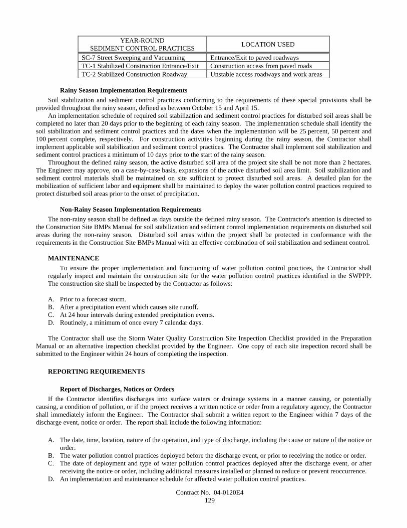
Contract No. 04-0120E4129
YEAR-ROUNDSEDIMENT CONTROL PRACTICES LOCATION USED
SC-7 Street Sweeping and Vacuuming Entrance/Exit to paved roadwaysTC-1 Stabilized Construction Entrance/Exit Construction access from paved roadsTC-2 Stabilized Construction Roadway Unstable access roadways and work areas
Rainy Season Implementation RequirementsSoil stabilization and sediment control practices conforming to the requirements of these special provisions shall be
provided throughout the rainy season, defined as between October 15 and April 15.An implementation schedule of required soil stabilization and sediment control practices for disturbed soil areas shall be
completed no later than 20 days prior to the beginning of each rainy season. The implementation schedule shall identify thesoil stabilization and sediment control practices and the dates when the implementation will be 25 percent, 50 percent and100 percent complete, respectively. For construction activities beginning during the rainy season, the Contractor shallimplement applicable soil stabilization and sediment control practices. The Contractor shall implement soil stabilization andsediment control practices a minimum of 10 days prior to the start of the rainy season.
Throughout the defined rainy season, the active disturbed soil area of the project site shall be not more than 2 hectares.The Engineer may approve, on a case-by-case basis, expansions of the active disturbed soil area limit. Soil stabilization andsediment control materials shall be maintained on site sufficient to protect disturbed soil areas. A detailed plan for themobilization of sufficient labor and equipment shall be maintained to deploy the water pollution control practices required toprotect disturbed soil areas prior to the onset of precipitation.
Non-Rainy Season Implementation RequirementsThe non-rainy season shall be defined as days outside the defined rainy season. The Contractor's attention is directed to
the Construction Site BMPs Manual for soil stabilization and sediment control implementation requirements on disturbed soilareas during the non-rainy season. Disturbed soil areas within the project shall be protected in conformance with therequirements in the Construction Site BMPs Manual with an effective combination of soil stabilization and sediment control.
MAINTENANCETo ensure the proper implementation and functioning of water pollution control practices, the Contractor shall
regularly inspect and maintain the construction site for the water pollution control practices identified in the SWPPP.The construction site shall be inspected by the Contractor as follows:
A. Prior to a forecast storm.B. After a precipitation event which causes site runoff.C. At 24 hour intervals during extended precipitation events.D. Routinely, a minimum of once every 7 calendar days.
The Contractor shall use the Storm Water Quality Construction Site Inspection Checklist provided in the PreparationManual or an alternative inspection checklist provided by the Engineer. One copy of each site inspection record shall besubmitted to the Engineer within 24 hours of completing the inspection.
REPORTING REQUIREMENTS
Report of Discharges, Notices or OrdersIf the Contractor identifies discharges into surface waters or drainage systems in a manner causing, or potentially
causing, a condition of pollution, or if the project receives a written notice or order from a regulatory agency, the Contractorshall immediately inform the Engineer. The Contractor shall submit a written report to the Engineer within 7 days of thedischarge event, notice or order. The report shall include the following information:
A. The date, time, location, nature of the operation, and type of discharge, including the cause or nature of the notice ororder.
B. The water pollution control practices deployed before the discharge event, or prior to receiving the notice or order.C. The date of deployment and type of water pollution control practices deployed after the discharge event, or after
receiving the notice or order, including additional measures installed or planned to reduce or prevent reoccurrence.D. An implementation and maintenance schedule for affected water pollution control practices.

Contract No. 04-0120E4130
Report of First-Time Non-Storm Water DischargeThe Contractor shall notify the Engineer at least 3 days in advance of first-time non-storm water discharge events,
excluding exempted discharges. The Contractor shall notify the Engineer of the operations causing non-storm waterdischarges and shall obtain field approval for first-time non-storm water discharges. Non-storm water discharges shall bemonitored at first-time occurrences and routinely thereafter.
Annual CertificationsBy June 15 of each year, the Contractor shall complete and submit an Annual Certification of Compliance, as contained
in the Preparation Manual, to the Engineer.
SAMPLING AND ANALYTICAL REQUIREMENTSThe Contractor is required to implement specific sampling and analytical procedures to determine whether BMPs
implemented on the construction site are: (a) preventing further impairment by sediment in storm waters discharged into theSan Francisco Bay for sediment, siltation or turbidity and (b) preventing other pollutants that are known or should be knownby the Contractor or Engineer to occur on construction sites that are not visually detectable in storm water discharges, fromcausing or contributing to exceedances of water quality objectives.
The project has the potential to discharge non-visible pollutants in storm water from the construction site. The projectSWPPP shall contain a Sampling and Analysis Plan (SAP) that describes the sampling and analysis strategy and schedule tobe implemented on the project for monitoring non-visible pollutants in conformance with this section.
The SAP shall identify potential non-visible pollutants that are known or should be known to occur on the constructionsite associated with the following: (1) construction materials, wastes or operations; (2) known existing contamination due tohistorical site usage; or (3) application of soil amendments, including soil stabilization products, with the potential to alter pHor contribute toxic pollutants to storm water. Planned material and waste storage areas, locations of known existingcontamination, and areas planned for application of soil amendments shall be shown on the SWPPP Water Pollution ControlDrawings.
The SAP shall identify a sampling schedule for collecting a sample down gradient from the applicable non-visiblepollutant source and a sufficiently large uncontaminated control sample during the first two hours of discharge from rainevents during daylight hours which result in a sufficient discharge for sample collection. If run-on occurs onto thenon-visible pollutant source, a run-on sample that is immediately down gradient of the run-on to the Department's right ofway shall be collected. A minimum of 72 hours of dry weather shall occur between rain events to distinguish separate rainevents.
The SAP shall state that water quality sampling will be triggered when any of the following conditions are observedduring the required storm water inspections conducted before or during a rain event:
A. Materials or wastes containing potential non-visible pollutants are not stored under watertight conditions.B. Materials or wastes containing potential non-visible pollutants are stored under watertight conditions, but (1) a
breach, leakage, malfunction, or spill is observed; and (2) the leak or spill has not been cleaned up prior to the rainevent; and (3) there is the potential for discharge of non-visible pollutants to surface waters or drainage system.
C. Construction activities such as Portland cement concrete grinding or saw cutting, or the application of fertilizer,pesticide, herbicide, or curing compound have occurred during a rain event or within 24 hours preceding a rainevent, and there is the potential for discharge of pollutants to surface waters or drainage system.
D. Soil amendments, including soil stabilization products, with the potential to alter pH levels or contribute toxicpollutants to storm water runoff have been applied, and there is the potential for discharge of pollutants to surfacewaters or drainage system (unless independent test data are available that demonstrate acceptable concentrationlevels of non-visible pollutants in the soil amendment).
E. Storm water runoff from an area contaminated by historical usage of the site is observed to combine with stormwater, and there is the potential for discharge of pollutants to surface waters or drainage system.
The SAP shall identify sampling locations for collecting down gradient and control samples, and the rationale for theirselection. The control sampling location shall be selected where the sample does not come into contact with materials,wastes or areas associated with potential non-visible pollutants or disturbed soil areas. Sampling locations shall be shown onthe SWPPP Water Pollution Control Drawings. Only trained personnel shall collect water quality samples and be identifiedin the SAP. Qualifications of designated sampling personnel shall describe training and experience, and shall be included inthe SWPPP. The SAP shall state monitoring preparation, sample collection procedures, quality assurance/quality control,sample labeling procedures, sample collection documentation, sample shipping and chain of custody procedures, samplenumbering system, and reference the construction site health and safety plan.
Contract No. 04-0120E4131
The SAP shall identify the analytical method to be used for analyzing down gradient and control samples for potentialnon-visible pollutants on the project. For samples analyzed in the field by sampling personnel, collection, analysis, andequipment calibration shall be in conformance with the Manufacturer's specifications. For samples that will be analyzed by alaboratory, sampling, preservation, and analysis shall be performed by a State-certified laboratory in conformance with 40CFR 136. The SAP shall identify the specific State-certified laboratory, sample containers, preservation requirements,holding times, and analysis method to be used. A list of State-certified laboratories that are approved by the Department isavailable at the following internet site: http://www.dhs.ca.gov/ps/ls/elap/html/lablist_county.htm.
The Contractor shall submit a hard copy and electronic copy of water quality analytical results and qualityassurance/quality control data to the Engineer within 5 days of sampling for field analyses and within 30 days for laboratoryanalyses. Analytical results shall be accompanied by an evaluation from the Contractor to determine if down gradientsamples show elevated levels of the tested parameter relative to levels in the control sample. If down gradient ordownstream samples, as applicable, show increased levels, the Contractor will assess the BMPs, site conditions, andsurrounding influences to determine the probable cause for the increase. As determined by the assessment, the Contractorwill repair or modify BMPs to address increases and amend the SWPPP as necessary. Electronic results (in one of thefollowing file formats: .xls, .txt, .csv, .dbs, or .mdb) shall have at a minimum the following information: sample identificationnumber, contract number, constituent, reported value, method reference, method detection limit, and reported detection limit.The Contractor shall document sample collection during rain events.
Water quality sampling documentation and analytical results shall be maintained with the SWPPP on the project siteuntil a Notice of Completion has been submitted and approved.
If construction activities or knowledge of site conditions change, such that discharges or sampling locations change, theContractor shall amend the SAP in conformance with this section, "Water Pollution Control."
PAYMENTThe contract lump sum price paid for prepare storm water pollution prevention plan shall include full compensation for
furnishing all labor, materials, tools, equipment, and incidentals for doing all the work involved in developing, preparing,obtaining approval of, revising, and amending the SWPPP, as specified in the Standard Specifications and these specialprovisions, and as directed by the Engineer.
Attention is directed to Section 9-1.06, "Partial Payments," and Section 9-1.07, "Payment After Acceptance," of theStandard Specifications. Payments for prepare storm water pollution prevention plan will be made as follows:
A. After the SWPPP has been approved by the Engineer, 75 percent of the contract item price for prepare storm waterpollution prevention plan will be included in the monthly partial payment estimate.
B. After acceptance of the contract in conformance with the provisions in Section 7-1.17, "Acceptance of Contract," ofthe Standard Specifications, payment for the remaining 25 percent of the contract item price for prepare storm waterpollution prevention plan will be made in conformance with the provisions in Section 9-1.07.
The contract lump sum price paid for water pollution control shall include full compensation for furnishing all labor,materials, tools, equipment, and incidentals, and for doing all the work involved in installing, constructing, removing, anddisposing of water pollution control practices, including non-storm water management, and waste management and materialspollution water pollution control practices, except those for which there is a contract item of work as specified in theStandard Specifications and these special provisions, and as directed by the Engineer.
Storm water sampling and analysis will be paid for as extra work as provided in Section 4-1.03D, "Extra Work," of theStandard Specifications. No payment will be made for the preparation, collection, analysis, and reporting of storm watersamples required where appropriate BMPs are not implemented prior to a rain event, or if a failure of a BMP is not correctedprior to a rain event.
For items identified on the approved Water Pollution Control Cost Break-Down, the cost of maintaining the temporarywater pollution control practices shall be divided equally by the State and the Contractor as follows:
Soil StabilizationTemporary water pollution control practices except:
SS-1 SchedulingSS-2 Preservation of Existing Vegetation
Sediment ControlTemporary water pollution control practices except:
SC-7 Street Sweeping and Vacuuming
Contract No. 04-0120E4132
Wind Erosion ControlNo sharing of maintenance costs will be allowed.
Tracking ControlTC-1 Stabilized Construction Entrance/Exit.
Non-Storm Water ManagementNo sharing of maintenance costs will be allowed.
Waste Management & Materials Pollution ControlNo sharing of maintenance costs will be allowed.
The division of cost will be made by determining the cost of maintaining water pollution control practices inconformance with the provisions in Section 9-1.03, "Force Account Payment," of the Standard Specifications and paying tothe Contractor one-half of that cost. Cleanup, repair, removal, disposal, improper installation, and replacement of waterpollution control practices damaged by the Contractor's negligence, shall not be considered as included in the cost forperforming maintenance.
The provisions for sharing maintenance costs shall not relieve the Contractor from the responsibility for providingappropriate maintenance on items with no shared maintenance costs.
Full compensation for non-shared maintenance costs of water pollution control practices, as specified in this section,"Water Pollution Control," shall be considered as included in the contract lump sum price paid for water pollution controland no additional compensation will be allowed therefor.
Water pollution control practices for which there is a contract item of work, will be measured and paid for as thatcontract item of work.
10-1.03 TURBIDITY CONTROLTurbidity control work shall conform to Section 7-1.01G, "Water Pollution," of the Standard Specifications, the plans,
these special provisions, and with all regulatory permits and waste discharge requirements pertaining to any work that has thepotential to cause turbidity within the project limits. Turbidity control work shall consist of implementing control measuresto limit transport of disturbed sediment into environmentally sensitive areas (ESA). Except as specified in the StandardSpecifications and these special provisions, compliance monitoring for turbidity will be performed by the Engineer inconformance with regulatory permits, waste discharge requirements and a turbidity monitoring program developed by theDepartment.
Attention is directed to "Environmentally Sensitive Areas (General)" of these special provisions.The Contractor shall be responsible for the costs and for liabilities imposed by law as a result of the Contractor's failure
to comply with the provisions set forth in this section "Turbidity Control", including but not limited to, compliance with theapplicable provisions of Permits, and Federal, State and local regulations. Costs and liabilities include, but are not limited to,fines, penalties, and damages whether assessed against the State or the Contractor, including those levied under the FederalClean Water Act and the State Porter Cologne Water Quality Act.
In addition to the remedies authorized by law, money due the Contractor under the contract, in an amount determined bythe Department, may be retained by the State of California until disposition has been made of the costs and liabilities.
When a regulatory agency or other third party identifies a failure to comply with the permit or any other local, State, orfederal requirement, the Engineer may retain money due the Contractor, subject to the following:
A. The Department will give the Contractor 30 days notice of the Department's intention to retain funds from partialpayments which may become due to the Contractor prior to acceptance of the contract. Retention of funds frompayments made after acceptance of the contract may be made without prior notice to the Contractor.
B. No retention of additional amounts out of partial payments will be made if the amount to be retained does notexceed the amount being withheld from partial payments pursuant to Section 9-1.06, "Partial Payments," of theStandard Specifications.
C. If the Department has retained funds and it is subsequently determined that the State is not subject to the costs andliabilities in connection with the matter for which the retention was made, the Department shall be liable for intereston the amount retained for the period of the retention, and the rate of interest payable shall be 6 percent per annum.
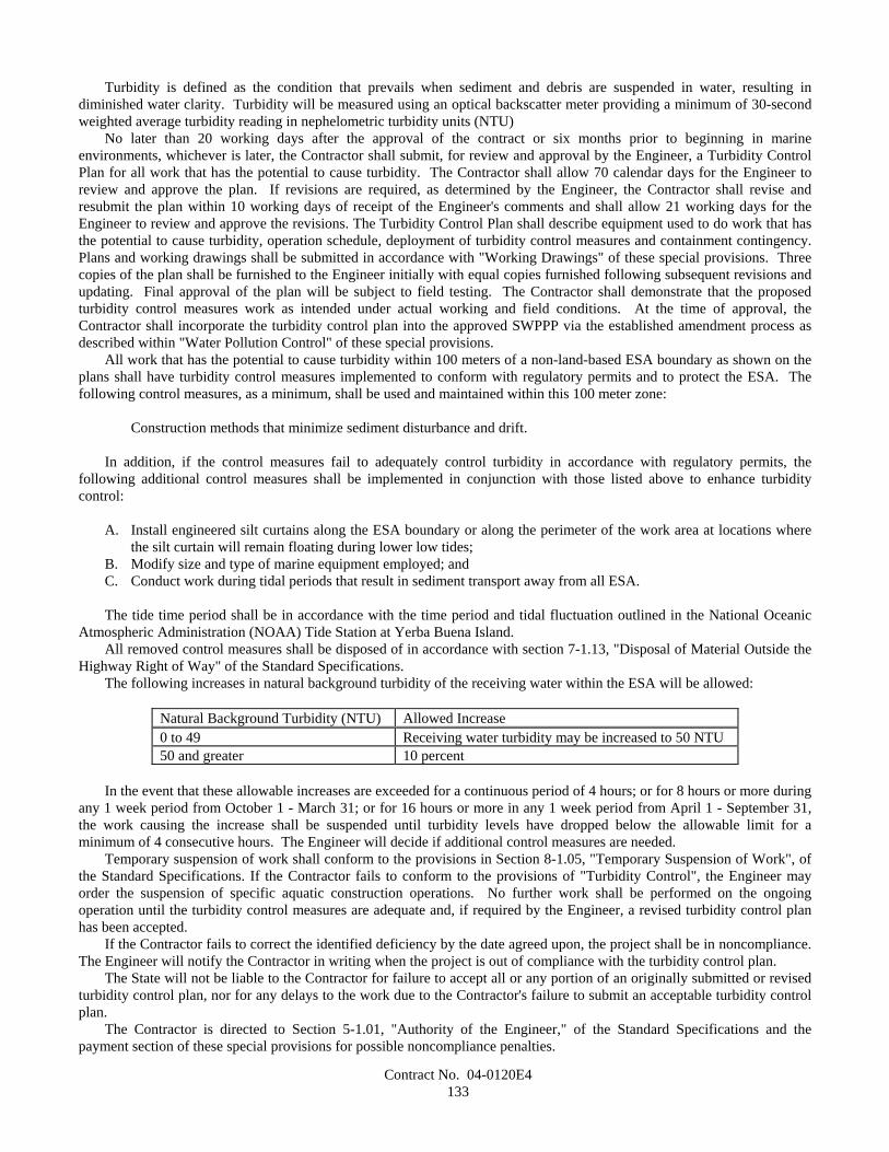
Contract No. 04-0120E4133
Turbidity is defined as the condition that prevails when sediment and debris are suspended in water, resulting indiminished water clarity. Turbidity will be measured using an optical backscatter meter providing a minimum of 30-secondweighted average turbidity reading in nephelometric turbidity units (NTU)
No later than 20 working days after the approval of the contract or six months prior to beginning in marineenvironments, whichever is later, the Contractor shall submit, for review and approval by the Engineer, a Turbidity ControlPlan for all work that has the potential to cause turbidity. The Contractor shall allow 70 calendar days for the Engineer toreview and approve the plan. If revisions are required, as determined by the Engineer, the Contractor shall revise andresubmit the plan within 10 working days of receipt of the Engineer's comments and shall allow 21 working days for theEngineer to review and approve the revisions. The Turbidity Control Plan shall describe equipment used to do work that hasthe potential to cause turbidity, operation schedule, deployment of turbidity control measures and containment contingency.Plans and working drawings shall be submitted in accordance with "Working Drawings" of these special provisions. Threecopies of the plan shall be furnished to the Engineer initially with equal copies furnished following subsequent revisions andupdating. Final approval of the plan will be subject to field testing. The Contractor shall demonstrate that the proposedturbidity control measures work as intended under actual working and field conditions. At the time of approval, theContractor shall incorporate the turbidity control plan into the approved SWPPP via the established amendment process asdescribed within "Water Pollution Control" of these special provisions.
All work that has the potential to cause turbidity within 100 meters of a non-land-based ESA boundary as shown on theplans shall have turbidity control measures implemented to conform with regulatory permits and to protect the ESA. Thefollowing control measures, as a minimum, shall be used and maintained within this 100 meter zone:
Construction methods that minimize sediment disturbance and drift.
In addition, if the control measures fail to adequately control turbidity in accordance with regulatory permits, thefollowing additional control measures shall be implemented in conjunction with those listed above to enhance turbiditycontrol:
A. Install engineered silt curtains along the ESA boundary or along the perimeter of the work area at locations wherethe silt curtain will remain floating during lower low tides;
B. Modify size and type of marine equipment employed; andC. Conduct work during tidal periods that result in sediment transport away from all ESA.
The tide time period shall be in accordance with the time period and tidal fluctuation outlined in the National OceanicAtmospheric Administration (NOAA) Tide Station at Yerba Buena Island.
All removed control measures shall be disposed of in accordance with section 7-1.13, "Disposal of Material Outside theHighway Right of Way" of the Standard Specifications.
The following increases in natural background turbidity of the receiving water within the ESA will be allowed:
Natural Background Turbidity (NTU) Allowed Increase0 to 49 Receiving water turbidity may be increased to 50 NTU50 and greater 10 percent
In the event that these allowable increases are exceeded for a continuous period of 4 hours; or for 8 hours or more duringany 1 week period from October 1 - March 31; or for 16 hours or more in any 1 week period from April 1 - September 31,the work causing the increase shall be suspended until turbidity levels have dropped below the allowable limit for aminimum of 4 consecutive hours. The Engineer will decide if additional control measures are needed.
Temporary suspension of work shall conform to the provisions in Section 8-1.05, "Temporary Suspension of Work", ofthe Standard Specifications. If the Contractor fails to conform to the provisions of "Turbidity Control", the Engineer mayorder the suspension of specific aquatic construction operations. No further work shall be performed on the ongoingoperation until the turbidity control measures are adequate and, if required by the Engineer, a revised turbidity control planhas been accepted.
If the Contractor fails to correct the identified deficiency by the date agreed upon, the project shall be in noncompliance.The Engineer will notify the Contractor in writing when the project is out of compliance with the turbidity control plan.
The State will not be liable to the Contractor for failure to accept all or any portion of an originally submitted or revisedturbidity control plan, nor for any delays to the work due to the Contractor's failure to submit an acceptable turbidity controlplan.
The Contractor is directed to Section 5-1.01, "Authority of the Engineer," of the Standard Specifications and thepayment section of these special provisions for possible noncompliance penalties.
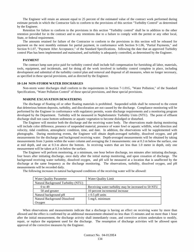
Contract No. 04-0120E4134
The Engineer will retain an amount equal to 25 percent of the estimated value of the contract work performed duringestimate periods in which the Contractor fails to conform to the provisions of this section "Turbidity Control" as determinedby the Engineer.
Retention for failure to conform to the provisions in this section "Turbidity control" shall be in addition to the otherretention provided for in the contract and to any retentions due to a failure to comply with the permit or any other local,State, or federal requirement.
The amounts retained for failure of the Contractor to conform to the provisions in this section will be released forpayment on the next monthly estimate for partial payment, in conformance with Section 9-1.06, "Partial Payments," andSection 9-1.07, "Payment After Acceptance," of the Standard Specifications, following the date that an approved Turbiditycontrol Plan has been implemented and maintained, and turbidity is adequately controlled, as determined by the Engineer.
PAYMENTThe contract lump sum price paid for turbidity control shall include full compensation for furnishing all labor, materials,
tools, equipment, and incidentals, and for doing all the work involved in turbidity control complete in place, includingdevelopment and submittal of the turbidity control plan and removal and disposal of all measures, when no longer necessary,as specified in these special provisions, and as directed by the Engineer.
10-1.04 NON-STORM WATER DISCHARGESNon-storm water discharges shall conform to the requirements in Section 7-1.01G, "Water Pollution," of the Standard
Specifications, "Water Pollution Control" of these special provisions, and these special provisions.
MARINE EXCAVATION DEWATERINGThe discharge of floating oil or other floating materials is prohibited. Suspended solids shall be removed to the extent
that deleterious bottom deposits, turbidity, and discoloration are not caused by the discharge. Compliance monitoring will beperformed by the Engineer in conformance with regulatory permits, waste discharge requirements and a monitoring programdeveloped by the Department. Turbidity will be measured in Nephelometric Turbidity Units (NTU). The point of effluentdischarge shall not cause bottom sediments or aquatic vegetation to become dislodged or disturbed.
The Engineer will monitor both the discharge and the receiving water body. The observations made during monitoringwill include color difference, presence of suspended material, presence of water fowl or aquatic wildlife, wind direction andvelocity, tidal condition, atmospheric condition, time, and date. In addition, the observations will be supplemented withphotographs. During monitoring events, the Engineer will obtain depth-averaged turbidity, dissolved oxygen, and pHmeasurements for the discharge and background receiving water. Depth-averaged measurements will be obtained by takingmeasurements from 3 points within the water column and averaging the 3 measurements: one at 0.3 m below the surface, oneat mid depth, and one at 0.3 m above the bottom. In receiving waters that are less than 1.0 meter in depth, only onemeasurement will be taken at 0.3 m below the surface.
The Engineer will perform monitoring, at a minimum, one hour before discharge, ten minutes after initiating discharge,four hours after initiating discharge, once daily after the initial startup monitoring, and upon cessation of discharge. Thebackground receiving water turbidity, dissolved oxygen, and pH will be measured at a location that is unaffected by thedischarge at the same frequency as the discharge monitoring. The observations, turbidity, dissolved oxygen, and pHmeasurements will be recorded daily.
The following increases in natural background conditions of the receiving water will be allowed:
Water Quality Parameter Water Quality LimitNatural Background Turbidity (NTU)
0 to 49 Receiving water turbidity may be increased to 50 NTU50 and greater 10 percent incremental increase
Natural background pH ± 0.5 pH unitsNatural Background DissolvedOxygen
5 mg/L minimum
When observations and measurements indicate that a discharge is having an effect on receiving water by more thanallowed and the effect is confirmed by an additional measurement obtained no less than 15 minutes and no more than 1 hourafter the initial measurement, the discharge activity shall immediately cease, and corrective actions undertaken to modify,repair, or replace the equipment used for the discharge. The resumption of discharge activities will be allowed uponapproval of the corrective measures by the Engineer.
Contract No. 04-0120E4135
The Contractor shall submit a Dewatering Plan to the Engineer, as specified in "Working Drawing," of these specialprovisions. The Dewatering Plan shall include the following:
A. Dewatering Operation Description - written description of all dewatering operations that shall include, but is notlimited to, start up date of discharge, an estimate of the discharge volume, flow rate, and frequency.
B. Working Drawings - working drawings of dewatering operations showing both a sectional and plan view thatdetails the removal techniques for suspended solids and known or introduced contaminants. The drawings shalldefine the flow path and placement of pipes, hoses, pumps, treatment systems, holding tanks, and other equipmentused to convey the discharge; the general position of the dewatering measures relative to the excavationsundergoing dewatering; and the point of effluent discharge.
The plan shall be submitted in the draft Storm Water Pollution Prevention Plan (SWPPP) or as an amendment to theSWPPP before beginning dewatering operations.
Holding tanks for pre-discharge storage shall be transportable and totally enclosed, with a minimum holding capacitysufficient to prevent delay of other work and capable of connecting multiple tanks in series. Holding tanks shall have aninlet and outlet capable of receiving and discharging minimum flows, at a rate sufficient to reach the treatment goals.Holding tanks shall be able to accommodate temporary installation of submersible pumps.
INSPECTIONThe Contractor shall conduct a daily inspection of the dewatering equipment, when in use, and ensure that all
components are functional and routinely maintained to prevent leakage before removal of suspended solids and petroleumhydrocarbons. If any component of the dewatering equipment is damaged so that the performance of the equipment isdiminished below allowable operational levels, the dewatering operation shall be discontinued and the component shall berepaired or replaced with substitute equipment.
SPILL CONTINGENCYThe Contractor shall prepare and submit to the Engineer a contingency plan for the management of spills or leaks of any
materials or wastes that may impact the water quality of the San Francisco Bay.The spill contingency plan shall be incorporated within the SWPPP, as specified in "Water Pollution Control" of these
special provisions.The contingency plan shall include instructions and procedures for reporting spills, and a list of spill containment and
collection materials and equipment to be maintained onsite. The contingency plan shall be reviewed and updated quarterly.
LIQUIDS, RESIDUES AND DEBRISThe Contractor shall prevent the discharge of slurries, liquids, residues, or debris produced during the work to storm
water facilities or surface waters of the State. The SWPPP shall, at a minimum, depict and describe the procedural andstructural methods of detaining, collecting, and disposing of all slurries, liquids, residues, and debris associated with theoperations. Sufficient redundancy shall be incorporated into the procedural and structural methods such that the slurries,liquids, residues, and debris are not conveyed into or become present in drainage systems, San Francisco Bay, or other waterbodies.
PAYMENTThe contract lump sum price paid for non-storm water discharges shall include full compensation for furnishing all
labor, materials, tools, equipment, and incidentals and for doing all the work involved in non-storm water discharges,complete in place, as specified in the Standard Specifications, and these special provisions, and as directed by the Engineer.
10-1.05 TEMPORARY CONCRETE WASHOUT FACILITYTemporary concrete washout facilities shall be constructed, maintained, and later removed in conformance with the
details as shown on the plans, as specified in these special provisions and as directed by the Engineer.Attention is directed to "Water Pollution Control" of these special provisions.Temporary concrete washout facilities shall be used as one of the various measures to prevent water pollution. The
Storm Water Pollution Prevention Plan (SWPPP) shall include the use of temporary concrete washout facilities.
MATERIALS

Contract No. 04-0120E4136
Plastic LinerPlastic liner shall be single ply, new polyethylene sheeting, a minimum of 0.25-mm thick and shall be free of holes,
punctures, tears or other defects that compromise the impermeability of the material. Plastic liner shall not have seams oroverlapping joints.
Gravel-filled BagsGravel-filled bag fabric shall be non-woven polypropylene geotextile (or comparable polymer), with a minimum unit
weight of 235 g/m2. The fabric shall have a minimum grab tensile strength of 0.89-kilonewtons in conformance to therequirements in ASTM Designation: D 4632, 25-mm grip, and an ultraviolet (UV) stability of 70 percent tensile strengthretained after 500 hours in conformance to the requirements in ASTM Designation: D 4355, xenon arc lamp method.
Gravel-filled bags shall be between 600 mm and 800 mm in length, and between 400 mm and 500 mm in width.Gravel shall be between 5 mm and 75 mm in diameter, and shall be clean and free from clay balls, organic matter, and
other deleterious materials. The opening of gravel-filled bags shall be secured such that gravel does not escape. Gravel-filled bags shall be between 13 kg and 22 kg in mass.
Straw BalesStraw for straw bales shall conform to the provisions in Section 20-2.06, "Straw," of the Standard Specifications.Straw bales shall be a minimum of 360 mm in width, 450 mm in height, 900 mm in length and shall have a minimum
mass of 23 kg. The straw bale shall be composed entirely of vegetative matter, except for binding material.Straw bales shall be bound by either wire, nylon or polypropylene string. Jute or cotton binding shall not be used. Wire
shall be a minimum 1.57 mm (16-gage) baling wire. Nylon or polypropylene string shall be approximately 2 mm in diameterwith 360 N of breaking strength.
StakesStakes shall be 50 mm x 50 mm wood posts. Metal stakes may be used as an alternative, and shall be a minimum 13 mm
in diameter. Stakes shall be a minimum 1200 mm in length. The tops of the metal stakes shall be bent at a 90-degree angleor capped with an orange or red plastic safety cap that fits snugly to the metal stake. The Contractor shall submit a sample ofthe metal stake and plastic cap, if used, to the Engineer prior to installation.
StaplesStaples shall be as shown on the plans.
SignsSigns shall be constructed as shown on the plans. Wood posts shall conform to the provisions in Section 56-2.02B,
"Wood Posts," of the Standard Specifications. Lag screws shall conform to the provisions in Section 56-2.02D, "Sign PanelFastening Hardware," of the Standard Specifications.
Plywood shall be freshly painted for each installation with not less than 2 applications of flat white paint. Sign lettersshown on the plans shall be stenciled with commercial quality exterior black paint. Testing of paint will not be required.
INSTALLATIONTemporary concrete washout facilities shall be installed on grade or below grade as shown on the plans and as follows:
A. Temporary concrete washout facilities shall be installed prior to beginning placement of concrete and located aminimum of 15 m from storm drain inlets, open drainage facilities, and water courses unless determined infeasibleby the Engineer. Temporary concrete washout facilities shall be located away from construction traffic or accessareas at a location determined by the Contractor and approved by the Engineer.
B. A sign shall be installed adjacent to each washout facility at a location determined by the Contractor and approvedby the Engineer. Signs shall be installed in conformance with the provisions in Section 56-2.03, "Construction,"and Section 56-2.04, "Sign Panel Installation," of the Standard Specifications and as shown on the plans.
C. The length and width of a temporary concrete washout facility may be increased from the minimum dimensionsshown on the plans, at the Contractor's expense and upon approval of the Engineer.
D. Temporary concrete washout facilities shall be constructed in sufficient quantity and size to contain all liquid andconcrete waste generated by washout operations for all concrete wastes. These facilities shall be constructed tocontain all liquid and concrete waste without seepage, spillage or overflow.
E. Berms for below grade temporary concrete washout facilities shall be constructed from compacted native material.Gravel may be used in conjunction with compacted native material
Contract No. 04-0120E4137
The Contractor may use an alternative temporary concrete washout facility if approved by the Engineer in writing. TheContractor shall submit details for an alternative temporary concrete washout facility to the Engineer in the draft SWPPP oras an amendment to the approved SWPPP in conformance with "Water Pollution Control" of these special provisions. Anyincrease in cost, including maintenance costs, for the alternative temporary concrete washout facility shall be borne by theContractor. The alternative temporary concrete washout facility shall be installed and maintained in conformance with thesespecial provisions.
When temporary concrete washout facilities are no longer required for the work, as determined by the Engineer, thehardened concrete and liquid residue shall be removed and disposed of in conformance with the provisions inSection 15-3.02, "Removal Methods," of the Standard Specifications. Material used to construct temporary concretewashout facilities shall become the property of the Contractor, shall be removed from the site of the work, and shall bedisposed of in conformance with the provisions in Section 7-1.13, "Disposal of Material Outside the Highway Right ofWay," of the Standard Specifications.
Holes, depressions or other ground disturbance caused by the installation and removal of the temporary concretewashout facilities shall be backfilled and repaired in conformance with the provisions in Section 15-1.02, "Preservation ofProperty," of the Standard Specifications.
MAINTENANCETemporary concrete washout facilities shall be maintained to provide adequate holding capacity with a minimum
freeboard of 300 mm. Maintaining temporary concrete washout facilities shall include removing and disposing of hardenedconcrete and returning the facilities to a functional condition. Hardened concrete materials shall be removed and disposed ofin conformance with the provisions in Section 15-3.02, "Removal Methods," of the Standard Specifications. Holes, rips, andvoids in the plastic liner shall be patched and repaired by taping or the plastic liner shall be replaced. Plastic liner shall bereplaced when patches or repairs compromise the impermeability of the material as determined by the Engineer.
PAYMENTThe contract lump sum price paid for temporary concrete washout facility shall include full compensation for furnishing
all labor, materials, tools, equipment and incidentals, and for doing all the work involved in constructing temporary concretewashout facilities, complete in place, including maintenance, removal of materials, and backfilling and repairing holes,depressions and other ground disturbance, as shown on the plans, as specified in the Standard Specifications and thesespecial provisions, and as directed by the Engineer.
10-1.06 COOPERATIONAttention is directed to Section 7-1.14, "Cooperation," and Section 8-1.10, "Utility and Non-Highway Facilities," of the
Standard Specifications and these special provisions.It is anticipated that work by other contractors may be in progress adjacent to or within the limits of this project during
progress of the work on this contract. The Contractor shall be responsible for coordinating with other contractors performingwork within these contract limits.
Contracts which may be in progress during the working period of this contract, include, but are not necessarily limited tothe following:
1. Contract No. 04-012024 constructing San Francisco-Oakland Bay Bridge structures, Route 80, in the City andCounty of San Francisco and Alameda County, between KP 1.6 (PM 1.0) and KP 1.6 (PM 1.0), adjacent to theeastern limit of the project site.
2. Contract No. 04-0120C4 constructing Piers W2 for Main Span Bridge structures, in the City and County of SanFrancisco, on Route 80, at Yerba Buena Island at KP 13.2 (PM 8.2), adjacent to the western limit of the project site.
3. Contract No. 04-0120G4 providing San Francisco-Oakland viaduct retrofit, demolition of the existing Substationand garage, and construction of the new substation and garage, in the City and County of San Francisco, on Route80, at Yerba Buena Island, between KP 12.6 (PM 7.8) and KP 12.8 (PM 7.9)
4. Contract No. 04-0120F4 constructing Self-Anchored Suspension Bridge Superstructure, in the City and County ofSan Francisco, on Route 80, between Yerba Buena Island at KP 13.2 (PM 8.2) and the west end of Contract04-012024 at KP 13.9 (PM 8.7)
5. Contract No. 04-0120H4 reconstructing YBI structures and providing demolition of Building No. 75, in the Cityand County of San Francisco, on Route 80, at Yerba Buena Island, between KP 12.6 (PM 7.8) and KP 13.2 (PM8.2)
Contract No. 04-0120E4138
6. Contract No. 04-012044 constructing San Francisco-Oakland Bay Bridge approach structure and roadway on Route80, between the east end of Contract 04-012024 at KP 1.6 (PM 1.0) and San Francisco-Oakland Toll Plaza at KP3.2 (PM 2.0).
7. Contract No. 04-002974 constructing Toll Operation Building, and ramps, at the south side of the San Francisco-Oakland Toll Plaza, on Route 80, between KP 1.6 (PM 1.0) and KP 3.7 (PM 2.3), in Alameda County.
8. Contract No. 04-014004 constructing Maintenance Buildings and Maintenance roadway access and reconstructingramps, on Route 80, between KP 1.6 (PM 1.0) and San Francisco-Oakland Toll Plaza at KP 3.7 (PM 2.3), inAlameda County.
9. Contract No. 04-0435V4 providing Seismic Retrofit by Replacement, on Route 80 from West Anchorage SanFrancisco-Oakland Bay Bridge at KP 7.9 (PM 4.9) to 5th Street On/Off-Ramps at KP 9.5 (PM 5.9), in the City andCounty of San Francisco.
10. Contract 04-0435C4 providing Seismic Retrofit and Archeology Investigation, on Route 80, on Route 80 from WestAnchorage San Francisco-Oakland Bay Bridge at KP 7.9 (PM 4.9) to 5th Street On/Off-Ramps at KP 9.5 (PM 5.9),in the City and County of San Francisco.
11. Contract No. 04-043554 providing Seismic Retrofit, on Route 80 from 0.2 Mile East of San Francisco AnchorageSan Francisco-Oakland Bay Bridge at PM 5.8 (KP 9.3) to Yerba Buena Anchorage San Francisco-Oakland BayBridge at PM 7.6 (KP 12.2), in the City and County of San Francisco.
12. Contract No. 04-0435U4 providing Seismic Retrofit, on Route 80 from 0.2 Mile West of San Francisco AnchorageSan Francisco-Oakland Bay Bridge at PM 5.5 (KP 8.9) to East End of Yerba Buena Tunnel at PM 7.8 (KP 12.6), inthe City and County of San Francisco.
13. Contract No. 04-0120R4 constructing the YBI South-South Detour in the City and County of San Francisco, onRoute 80, at Yerba Buena Island, between KP 12.6 (PM 7.8) and KP 13.2 (PM 8.2).
Progress schedules for the above contracts, when available, may be inspected by the Contractor, such progress schedulesare tentative and no guarantee can be made by the State that such work will actually be performed as indicated by theschedules.
The Contractor shall attend joint weekly meetings, to be organized by the Engineer with other contractors on theadjacent projects in order to minimize potential conflicts. Furthermore, the Contractor shall be responsible for coordinatingwith other contractors, agencies or their authorized personnel or representative or by State forces performing work withinthese contract limits.
10-1.07 TRANSPORTATION FOR THE ENGINEERThe Contractor shall provide transportation for the Engineer in accordance with Section 5-1.08, "Inspection," of the
Standard Specifications and these special provisions.The Contractor shall provide, operate, berth and maintain, beginning with the first mobilization of marine equipment
until contract completion, one crew boat for the sole use of the Engineer and the Engineer's staff in performance of theirwork. In addition, the Engineer and all authorized representatives of the State, acting within the scope of their duties inconnection with the work under this contract, shall be permitted to ride as passengers, without charge, on any boat operatedby, or for, the Contractor for the transportation of personnel, equipment or materials. It is agreed that such transportationwill be only on the boats that are making trips in connection with the Contractor's operation.
The crew boat shall be 12 meters, adequate for open water operations, or equal, with protected seating and meeting orexceeding the following minimum requirements:
A. DRIVE POWER:
1. Engines – Diesel engines, 600 HP total, twin screw, capable of at least 25 knots.2. Fuel Tank – 173 gal. Tank
B. EQUIPMENT:
1. Aluminum or steel hull construction2. Tires or rubber fenders for fendering around the boat3. Mooring bits located forward and aft on boat4. 22 kg anchor with chain and line (adequate for specific site condition)
C. ELECTRONICS:
Contract No. 04-0120E4139
1. VHF/FM Radio System2. One (1) Com 58 or equal3. Radar system Furuno 1731 or equal4. Depth finder digital5. Compass Richie navigator 2 each or equal
United States Coast Guard-approved life jackets for the Contractor's personnel shall be provided and maintained on theboats at all times, as required by the United States Coast Guard. Life jackets for the Department's visitors andrepresentatives will be provided by the Department at no cost to the Contractor.
The Contractor shall provide for the Department's visitors and representatives safe and protected permanent verticalaccess, as approved by the Engineer, to all marine construction equipment being utilized for construction of the project.
The Contractor shall provide safety training relative to marine transportation to the State's and the Contractor'spersonnel, prior to the commencement of work. Training shall include a review of the approved U.S. Coast Guard SafetyManual by all personnel prior to using the Contractor's provided marine transportation. The Contractor shall also conduct aquarterly Marine Safety Workshop for the Department's representatives.
The Contractor shall furnish a licensed boat operator and crew members, as required for the boat's operation and inaccordance with all Maritime Agreements and Laws, including, but not limited to, the regulations contained in Title 46 Codeof Federal Regulation Section 16 and Sections 24 through 26. The boat must have a valid U.S. Coast Guard Certificate ofInspection (COI), and must be manned and operated in accordance with the COI. The boat, boat operator and crew shall befurnished beginning with the first mobilization of marine equipment until contract completion for the duration of thecontract. The boat, boat operator and crew shall be furnished for the complete duration of the work on the days when theContractor's work is in progress and for 8 hours each day excluding Sundays and legal holidays on the days when theContractor's work is not in progress.
The Contractor shall provide insurance coverage under the Federal Longshoremen's and Harbor Workers CompensationAct, the Jones Act and the Marine Act with respect to work performed from, or by use of, vehicles on any navigable water ofthe United States, including liability insurance for watercraft operations. At the option of the Contractor, liability insurancefor watercraft operations may be covered under a separate Protection and Indemnity policy, provided the policy contains acombined single limit of at least $50,000,000 per occurrence and $50,000,000 aggregate.
The Contractor shall provide berthing facilities at the same location the Contractor utilizes for the departure of itsconstruction crew, or at an alternate location approved by the Engineer.
The Contractor shall maintain the boat provided to the Engineer, including daily fueling, routine maintenance,equipment compliance, systems operations and the immediate repair of damage to the boat or its elements.
The boat shall remain the property of the Contractor. The boat shall not be removed from the site of the work until afteracceptance of the contract.
The contract lump sum price paid for transportation for the engineer shall include full compensation for furnishing alllabor, materials, tools, equipment and incidentals, and for doing all the work involved in providing transportation for theengineer as specified herein.
Payment for furnishing a boat, boat operator and crew prior to the times specified and in excess of the complete durationof the work on the days when the Contractor's work is in progress, in excess of 8 hours per day excluding Sundays and legalholidays on the days when the contractor's work is not in progress, and on Sundays and legal holidays will be paid for asextra work as provided in Section 4-1.03D of the Standard Specifications.
10-1.08 ESTABLISH MARINE ACCESSThis work shall consist of furnishing, erecting, maintaining and removing barges, trestles and other facilities to provide
marine access to the job site. This work shall be separate from and in addition to the work specified in Section 11,"Mobilization," of the Standard Specifications.
The Contractor may construct an access trestle for access to the jobsite in accordance with the permits obtained by theDepartment and these special provisions.
The Contractor shall submit, for approval by the Engineer, in accordance with the provisions in "Working Drawings," ofthese special provisions, calculations and working drawings of any access trestle and other temporary facilities that are to beconstructed. The Contractor shall allow the Engineer 70 calendar days to review and approve the working drawings andsupplemental calculations. If revisions are required, as determined by the Engineer, the Contractor shall revise and resubmitthe working drawings and calculations within 14 working days of receipt of the Engineer's comments and shall allow 21working days for the Engineer to review the revisions.
The Contractor shall submit, for approval by the Engineer, a schedule of values detailing the cost breakdown of thecontract lump sum item for establish marine access. The schedule of values shall reflect the items, work, quantities and costsrequired to establish marine access to the job site, including as a minimum: initial mobilization of marine access facilities,
Contract No. 04-0120E4140
monthly facility and equipment rental, monthly maintenance, and demobilization. The Contractor shall be responsible for theaccuracy of the quantities and costs used in the schedule of values submitted for approval.
The sum of the amounts for the items and work listed in the schedule of values shall be equal to the contract lump sumprice for establish marine access.
The schedule of values for establish marine access shall be submitted to the Engineer within the time required forsubmittal of the Interim Baseline Schedule, as specified in "Progress Schedule (Critical Path Method)" of these specialprovisions.
When approved in writing by the Engineer, the schedule of values will be used to determine progress payments forestablish marine access during the progress of the work. No partial payment for establish marine access will be made untilthe schedule of values is approved in writing by the Engineer.
The contract lump sum price paid for establish marine access shall include full compensation for furnishing all labor,materials, tools, equipment, and incidentals, and for doing all the work involved in establishing marine access to the job site,as specified in the Standard Specifications and these special provisions, and as directed by the Engineer.
The adjustment provisions in Section 4-1.03C, "Changes," of the Standard Specifications shall not apply to the contractlump sum price for establish marine access. Full compensation for damages due to delays shall be considered as included inthe payments made in accordance with "Time-Related Overhead" of these special provisions and Section 8-1.09, "Right ofWay Delays," of the Standard Specifications and no additional compensation will be allowed therefor.
10-1.09 PROGRESS SCHEDULE (CRITICAL PATH METHOD)Progress schedules will be required for this contract. Progress schedules shall utilize the Critical Path Method (CPM).
Attention is directed to "Cooperation," and "Obstructions" of these special provisions. Nothing in these special provisionsshall be construed as relieving the Contractor from the responsibilities specified in Section 7, "Legal Relations andResponsibility," of the Standard Specifications. All schedules are required to reflect a reasonable plan to execute the contractscope of work. The Contractor shall be solely responsible for the content of the schedules and the execution of all contractrequirements.
The provisions in Section 8-1.04, "Progress Schedule," of the Standard Specifications shall not apply.
DEFINITIONSThe following definitions apply to this section "Progress Schedule (Critical Path Method)":
A. Activity: Any task, or portion of a project, which takes time to complete.B. Baseline Schedule: The initial CPM schedule representing the Contractor's original work plan, as accepted by
the Engineer.C. Controlling Operation: The activity considered at the time by the Engineer, within that series of activities
defined as the critical path, which if delayed or prolonged, will delay the time of completion of the contract.D. Critical Path: The series of activities, which determines the earliest completion of the contract (Forecast
Completion Date). This is the longest path of activities having the least amount of float.E. Critical Path Method: A mathematical calculation to determine the earliest completion of the contract
represented by a graphic representation of the sequence of activities that shows the interrelationships andinterdependencies of the elements composing a project.
F. Contract Completion Date: The current extended date for completion of the contract shown on the weeklystatement of working days furnished by the Engineer in accordance with Section 8-1.06, "Time of Completion,"of the Standard Specifications.
G. Early Completion Time: The difference in time between the current contract completion date and theContractor's scheduled early forecast completion date as shown on the accepted baseline schedule, or scheduleupdates and revisions.
H. Float: The amount of time between the early start date and the late start date, or the early finish date and the latefinish date, of any activity or group of activities in the network.
I. Scheduled Completion Date: The completion date of the last scheduled work activity identified on the criticalpath.
J. Free Float: The amount of time an activity can be delayed before affecting a subsequent activity.K. Hammock Activity: An activity added to the network to span an existing group of activities for summarizing
purposes.L. Milestone: A marker in a network, which is typically used to mark a point in time or denote the beginning or
end of a sequence of activities. A milestone has zero duration, but will otherwise function in the network as ifit were an activity.
Contract No. 04-0120E4141
M. Revision: A change in the future portion of the schedule that modifies logic, adds or deletes activities, or altersactivities, sequences, or durations.
N. Tabular Listing: A report showing schedule activities, their relationships, durations, scheduled and actual dates,and float.
O. Total Float: The amount of time that an activity may be delayed without affecting the total project duration ofthe critical path.
P. Update Schedule: The modification of the CPM progress schedule through a regular review to incorporateactual progress to date by activity and to reflect the current plan to complete the project.
Q. Time Scaled Logic Diagram: A schematic display of the logical relationships of project activities, drawn fromleft to right to reflect project chronology with the positioning and length of the activity representing itsduration.
R. Bar Chart (Gantt Chart): A graphic display of scheduled-related information, activities or other project elementsare listed down the left side of the chart, dates are shown across the top, and activity durations are shown asdate-placed horizontal bars.
S. Near Critical Path: A path having 30 working days or less of total float.T. Delay: The time period during which some part of the construction project has been extended beyond what was
originally planned due to unanticipated circumstances. A delay occurs when the respective activity or group ofactivities, requiring additional time, impacts the completion of the successor construction activity and alsoextend the scheduled contract completion date.
U. Data date: The day after the date through which a schedule is current. Everything occurring earlier than thedata date is "as-built" and everything on or after the data date is "planned."
V. Narrative Report: A document submitted with each schedule that discusses topics related to project progressand scheduling.
W. State Owned Float Activity: The activity documenting time saved on the critical path by actions of the State. Itis the last activity prior to the scheduled completion date.
X. Time Impact Analysis: A schedule and narrative report developed specifically to demonstrate what effect aproposed change or delay has on the current scheduled completion date.
The Engineer will schedule and conduct a Preconstruction Scheduling Conference with the Contractor's Project Managerand Construction Scheduler within seven days after the bidder has received the contract for execution. At this meeting, therequirements of this section of the special provisions will be reviewed with the Contractor. The Contractor shall be preparedto discuss its schedule methodology, proposed sequence of operations, the activity identification system for labeling all workactivities, the schedule file numbering system, and any deviations it proposes to make from the Stage Construction Plans.The Engineer will submit a scheduling shell project on electronic medium, displaying an activity code dictionary consistingof fields populated with the Caltrans scheduling codes, filters, layouts, report formats, contract milestones, and a resourcedictionary. The Contractor shall utilize these codes, filters, layouts, etc. and may add other codes as necessary, to group andorganize the work activities. Periodically the Engineer may request the Contractor to utilize additional filters, layouts oractivity codes to be able to further group or summarize work activities.
Also, the Engineer and the Contractor shall review the requirements for all submittals applicable to the contract anddiscuss their respective preparation and review durations. All submittals and reviews are to be reflected on the InterimBaseline Schedule and the Baseline Schedule.
GENERAL SCHEDULE ITEMSThe following items are applicable to all schedules:
A. Activity identification numbers for deleted activities are not to be reused. Added activities shall be assigned anew and unique activity identification number.
B. Activity descriptions are not to be revised when the scope of the activity is changed. The existing activity shallbe deleted and a new activity shall be added.
C. When forecasting new durations for activities that have not started, the original duration field shall be revised.D. All Resource requirements shall be included for all new construction activities.E. All activities shall have durations of not more than 20 working days and not less than one working day unless
permitted otherwise by the Engineer.F. All activities in the schedule, with the exception of the first and last activities, shall have a minimum of one
predecessor and a minimum of one successor.H. Negative lags shall not be assigned for any activity relationships.
Contract No. 04-0120E4142
I. All out of sequence activities identified on the scheduling and leveling report shall be reviewed and theirrelationships either verified or changed.
J. The Contractor shall not add job inefficiencies or weather days to a project calendar without prior approval bythe Engineer.
K. Offsite fabrication and material/equipment delivery activities shall be sufficiently detailed to allow monitoringof schedule progress.
L. The Contractor shall provide to the Engineer two copies of all schedules on electronic medium, together withprinted copies of the network diagrams or bar charts and tabular reports described under "Project ScheduleReports", and the Schedule Narrative Report.
The Engineer's review and acceptance of schedules shall not waive any contract requirements and shall not relieve theContractor of any obligation thereunder or responsibility for submitting complete and accurate information. Schedules thatare rejected shall be corrected by the Contractor and resubmitted to the Engineer within 7 working days of notification by theEngineer, at which time a new review will begin.
Errors or omissions on schedules shall not relieve the Contractor from finishing all work within the time limit specifiedfor completion of the contract. If, after a schedule has been accepted by the Engineer, either the Contractor of the Engineerdiscover that any aspect of the schedule has an error or omission, it shall be corrected by the Contractor on the next updateschedule.
INTERIM BASELINE SCHEDULEWithin 15 days after approval of the contract, the Contractor shall submit to the Engineer an Interim Baseline Project
Schedule which will serve as the progress schedule for the first 120 days of the project, or until the Baseline Schedule isaccepted, whichever is sooner. The Interim Baseline Schedule shall utilize the critical path method of scheduling. TheInterim Baseline Schedule shall depict how the Contractor plans to perform the work for the first 120 days of the contract.Additionally, the Interim Baseline Schedule shall show all required submittals working drawings, and review periods, andshall provide for all permits, and other non-work activities necessary to begin the work. The Contractor shall also submit aSummary Schedule, reflecting the duration of the contract, grouped by major areas of the project identified by the schedulingcodes provided in the Caltrans scheduling codes or as defined by the Engineer. This summary schedule is for informationpurposes only and is to be used as a reference until the Baseline Schedule is accepted.
The Interim Baseline Schedule submittal shall include the data files used to generate the schedule on electronic medium.The Engineer shall be allowed 10 days to review the schedule and to provide comments, including the Contractor's
application of the supplied activity codes. All comments are to be implemented into the Baseline Schedule. Re-submittal ofthe Interim Baseline Schedule is not required. Late review of the Interim Baseline Schedule shall not restrain the submittalof the Baseline Schedule. No contract payments shall be made to the Contractor until a Interim Baseline Schedule issubmitted in accordance with the above requirements.
BASELINE SCHEDULEWithin 45 days, after approval of the contract, the Contractor shall submit to the Engineer a Baseline Project Schedule
including the incorporation of all comments provided to the Interim Baseline Schedule. The Baseline Schedule shall have adata date of the day prior to the first working day of the contract. The schedule shall not include any actual start dates, actualfinish dates, or constraint dates (except for Contract Milestone dates) and activities scheduled to start or finish between thedata date and the run date shall reflect dates that can be attained. The Baseline Schedule shall meet interim milestone dates,contract milestone dates, stage construction requirements, internal time constraints, show logical sequence of activities, andmust not extend beyond the number of days originally provided for in the contract.
All task activities shall be assigned to a project calendar. Each calendar shall identify a workweek, and holidays.Different calendars shall be used for work activities that occur on different work schedules. Activities for the preparationand the review of submittals; offsite fabrication, and material/equipment deliveries are to be assigned to the same calendarunless approved by the Engineer. All non-activity periods for Environmental work restrictions shall be identified with theappropriate calendars.
The Baseline CPM Schedule submitted by the Contractor shall have a sufficient number of activities to assure adequateplanning of the project and to permit monitoring and evaluation of progress and the analysis of time impacts. The BaselineSchedule shall depict how the Contractor plans to complete the whole work involved, and shall show all activities that definethe critical path. Multiple critical paths and near-critical paths shall be kept to a minimum, as determined by the Engineer.
State owned float shall be considered a resource for the exclusive use of the State. The Engineer may accrue Stateowned float by the early completion of review of any type of required submittal when it saves time on the critical path. TheEngineer will document State owned float by directing the Contractor to update the State owned float activity on the nextschedule update. The Contractor shall include a log of the action on the State owned float activity and include a discussion
Contract No. 04-0120E4143
of the actions in the narrative report. The Engineer may use State owned float to mitigate past or future State delays byoffsetting potential time extensions for contract change work orders.
The Contractor shall be responsible for assuring that all work sequences are logical and the network shows a coordinatedplan for complete performance of the work. Failure of the Contractor to include any element of work required for theperformance of the contract in the network shall not relieve the Contractor from completing all work within the time limitspecified for completion of the contract. If the Contractor fails to define any element of work, activity or logic, theContractor in the next monthly update or revision of the schedule shall correct it.
The Baseline Schedule shall be supplemented with resource allocations for every task activity to a level of detail thatfacilitates report generation based on labor craft and equipment class for the Contractor and subcontractors.
The Contractor shall optimize labor to reflect a reasonable plan for accomplishing the work of the contract and to assurethat resources are not over committed in concurrent activities. The Contractor shall not create hammock activities for thepurpose of resources loading. The Baseline Schedule shall not attribute negative float to any activity.
Along with the baseline progress schedule, the Contractor shall also submit to the Engineer time-scaled resourcehistograms of the labor crafts and equipment to be utilized on the contract.
Each schedule submitted to the Engineer will comply with all limits imposed by the contract, with all specifiedintermediate milestone and contract completion dates, and with all constraints, restraints or sequences included in thecontract. The degree of detail shall include factors including, but not limited to:
A. Physical breakdown of the project;B. Contract milestones and completion dates, substantial completion dates, constraints, restraints, sequences of
work shown in the contract, the planned substantial completion date, and the final completion date;C. Type of work to be performed, the sequences, and the major subcontractors involved;D. All purchases, submittals, submittal reviews, manufacture, fabrication, tests, delivery, and installation activities
for all major materials and equipment, including submittal of requests for audits of manufacturers andfabricators in conformance with "Manufacturing and Fabrication Qualification Audit for Materials" of thesespecial provisions;
E. Preparation, submittal and approval of shop and working drawings and material samples, showing time, asspecified elsewhere, for the Engineer's review. The same time frame shall be allowed for at least oneresubmittal on all major submittals so identified in the contract documents.
F. Identification of interfaces and dependencies with preceding, concurrent and follow-on contractors, railroads,and utilities as shown on the plans or specified in the specifications;
G. Identification of each and every utility relocation and interface as a separate activity, including activitydescription and responsibility coding that identifies the type of utility and the name of the utility companyinvolved;
H. Actual tests, submission of test reports, and approval of test results;I. All start-up, testing, training, and assistance required under the Contract;J. Punchlist and final clean-up;K. Identification of any manpower, material, or equipment restrictions, as well as any activity requiring unusual
shift work, such as double shifts, 6-day weeks, specified overtime, or work at times other than regular days orhours;
L. Identification of each and every ramp closing and opening event as a separate one day activity, includingdesignation by activity coding and description that it is a north-bound, south-bound, east-bound, west-bound,and entry or exit ramp activity;
M. Separate resources graphs for the Contract's labor, equipment and critical path labor, with an accompanyinganalysis of each and explanation for any variances;
N. Equipment and labor shall be differentiated by a cost account code within the resource dictionary.O. State owned float as the last activity in the schedule, at the end of which is the Scheduled Completion Date.
The Engineer will be allowed 15 days to review and accept or reject the baseline project schedule submitted. Rejectedschedules shall be resubmitted to the Engineer within 5 days, at which time a new 15-day review period by the Engineer willbegin.
PROJECT SCHEDULE REPORTSSchedules submitted to the Engineer including Interim Baseline, Baseline, and update schedules shall include time
scaled network diagrams or bar charts in a layout format requested by the Engineer. The network diagrams or bar chartssubmitted to the Engineer shall also be accompanied by four computer-generated mathematical analysis tabular reports foreach activity included in the project schedule. The reports (215-mm x 915-mm size) shall include a network diagram report
Contract No. 04-0120E4144
showing the activity columns only, a predecessor and successor report, a resource report (Interim Baseline and BaselineSchedules), and a scheduling and leveling calculation report. The network diagram reports shall include, at a minimum, thefollowing for each activity:
A. Activity number and description;B. Activity codes;C. Original, actual and remaining durations;D. Early start date (by calendar date);E. Early finish date (by calendar date);F. Actual start date (by calendar date);G. Actual finish date (by calendar date);H. Late start date (by calendar date);I. Late finish date (by calendar date);J. Identify activity calendar ID;K. Total Float and Free Float, in work days; andL. Percentage complete.
Network diagrams or bar charts shall be sorted and grouped in a format requested by the Engineer reflecting the projectbreakdown per the Caltrans activity codes. They shall show a continuous flow of information from left to right per theproject sorting and grouping codes; e.g., project milestones, submittals sub-grouped by description, and the constructionactivities sub-grouped by the scope breakdown structure. The primary paths of criticality shall be clearly and graphicallyidentified on the diagrams or charts. The network diagram or bar chart shall be prepared on E-size sheets (910-mm by1200-mm), shall have a title block in the lower right-hand corner, and a timeline on each page. Exceptions to the size of thenetwork sheets and the use of computer graphics to generate the networks or bar charts shall be subject to the approval of theEngineer.
Schedule network diagrams the tabular reports shall be submitted to the Engineer for acceptance in the followingquantities:
A. 2 sets of the Network Diagrams or Bar Charts;B. 2 copies of the tabular reports (215-mm x 915-mm size); andC. 2 copies on electronic medium, each with a backup of the current schedule file.
WEEKLY SCHEDULE MEETINGSThe Engineer and the Contractor shall hold weekly scheduling meetings to discuss the near term schedule activities, to
address any long-term schedule issues, and to discuss any relevant technical issues. The Contractor shall develop a rolling 4-weeks schedule identifying the previous week worked and a 3-week look ahead. It shall provide sufficient detail to includethe actual and planned activities of the Contractor and all the subcontractors for offsite and construction activities, addressingall activities to be performed and to identify issues requiring engineering action or input.
Each activity in the 4 week rolling schedule should be identified by an associated CPM schedule activity ID numberingsystem. This schedule should not be hand written. The Contractor shall utilize a schedule layout as acceptable by theEngineer. The schedule shall be electronically submitted to the Engineer one day prior to the scheduled meeting date.
MONTHLY CASH FLOW REPORTSThe Contractor shall allocate a portion of each bid item cost to the appropriate schedule activities. A minimum of one
activity shall be added to the schedule for each bid item. The total of all activity costs shall equal the total contract bidamount. This information shall be sufficient to generate a monthly cash flow report showing the anticipated monthlycontract progress payments. The format for the report shall be acceptable to the Engineer. Actual Progress Payments shall bemade in accordance with Standard Specification 9-1.06, Partial Payments.
MONTHLY UPDATE SCHEDULESThe Contractor shall submit a Monthly Update Schedule to the Engineer once in each month within 5 days of the data
date. The proposed update schedule prepared by the Contractor shall include all information available as of the 20th calendarday of the month, or other data date as established by the Engineer. A detailed list of all proposed schedule changes such aslogic, duration, lead/lag, forecast completion date, additions and deletions shall be submitted with the update.
The Monthly Update Schedule submitted to the Engineer will be accompanied by a Schedule Narrative Report. Thereport shall describe the physical progress during the report period, plans for continuing the work during the forthcomingreport period, actions planned to correct any negative float, and an explanation of potential delays or problems and their

Contract No. 04-0120E4145
estimated impact on performance, milestone completion dates, forecast completion date, and the overall project completiondate. In addition, alternatives for possible schedule recovery to mitigate any potential delay or cost increases shall beincluded for consideration by the Engineer. The report shall follow the outline set forth below:
Contractor's Schedule Narrative Report Outline:
A. Contractor's Transmittal Letter;B. Work completed during the period;C. Description of the current critical path;D. Description of current problem areas;E. Current and anticipated delays;
1. Cause of the delay;2. Corrective action and schedule adjustments to correct the delay; and3. Impact of the delay on other activities, milestones, and completion dates;
F. Changes in construction sequences;G. Pending items and status thereof;
1. Permits;2. Change Orders;3. Time Extensions; and4. Non-Compliance Notices;5. Notice of Potential Claims
H. Contract completion date(s) status;
1. Ahead of schedule and number of days; and2. Behind schedule and number of days; and
I. Include updated Network Diagram and Reports.J. Response to Previous Schedule Comments
Portions of the network diagram on which all activities are complete need not be reprinted and submitted in subsequentupdates. However, the submitted schedule and the related reports shall constitute a clear record of progress of the work fromaward of contract to final completion.
On a date determined by the Engineer, the Contractor shall meet with the Engineer to review the monthly scheduleupdate. At the monthly progress meeting, the Contractor and the Engineer shall review the updated schedule and shalldiscuss the content of the Narrative Report. The Engineer will be allowed 10 days after the meeting to review and accept orreject the update schedule submitted. Rejected schedules shall be resubmitted to the Engineer within 5 days, at which time anew 5-day review period by the Engineer will begin. All efforts shall be made between the Engineer and the Contractor tocomplete the review and the acceptance process prior to the next update schedule data date. To expedite the process, asecond meeting between the Engineer and the Contractor may be held.
SCHEDULE REVISIONSIf the Contractor desires to make a change to the accepted schedule, the Contractor shall request permission from the
Engineer in writing, stating the reasons for the change, and proposed revisions to activities, logic and duration. TheContractor shall submit for acceptance an analysis showing the effect of the revisions on the entire project. The analysisshall include:
A. An updated schedule not including the revisions. The schedule shall have a data date just prior to implementingthe proposed revisions and includes a project completion date;
B. A revised schedule that includes the proposed revisions. The schedule will have the same data date as theupdated schedule and include a project completion date;
C. The Contractor should add resources for all new activities, also adjust resources for those activities that theirremaining duration were changed;
D. A narrative explanation of the revisions and their impact to the schedule;
Contract No. 04-0120E4146
E. Computer files of the updated schedule and the revised schedule sequentially numbered or renamed for archive(record) purposes.
The Engineer will provide a response within 10 days to Contractor's proposed schedule revisions.Within 15 calendar days, the Contractor shall submit a revised CPM network for approval when requested by the
Engineer, or when any of the following occurs:
A. There is a significant change in the Contractor's operations that will affect the critical path;B. The current updated schedule indicates that the contract progress is 4 weeks or more behind the planned
schedule, as determined by the Engineer; orC. The Engineer determines that an approved or anticipated change will impact the critical path, milestone or
completion dates, contract progress, or work by other contractors.
The Engineer shall be allowed 10 days to review and accept or reject a schedule revision. Rejected schedule revisionsshall be revised and resubmitted to the Engineer within 10 days, at which time a new 10-day review period by the Engineerwill begin. Only upon approval of a change by the Engineer shall it be reflected in the next schedule update submitted by theContractor. The revised schedule shall also include a narrative explanation of the revisions and their impact to the schedule.
TIME IMPACT ANALYSISWhen the Contractor requests a time adjustment due to contract change orders or delays or if the Contractor or the
Engineer considers that an approved or anticipated change will impact the critical path or contract progress, the Contractorshall submit to the Engineer a written Time Impact Analysis illustrating the impact of each change or delay on the currentscheduled completion date or milestone completion date, utilizing the current accepted schedule. Each Time ImpactAnalysis shall include a schedule update and schedule revision, both with the same data dates, demonstrating how theContractor proposes to incorporate the change order or delay into the current schedule. The schedule revision shall includethe sequence of activities and any revisions to the existing activities to demonstrate the impact of the delay, or change intothe schedule. The Time Impact Analysis shall also include proposed mitigation measures or work around including but notlimited to alternate work calendars, re-sequencing of other activities, or performing work activities out-of-sequence tominimize the impact of the change order or the disrupted activities.
Each Time Impact Analysis shall demonstrate the estimated time impact based on the events of delay, the anticipated oractual date of the contract change order work performance, the status of construction at that point in time, and the event timecomputation of all activities affected by the change or delay. The event times used in the analysis shall be those included inthe latest update of the current schedule in effect at the time the change or delay was encountered.
Time extensions will be granted only to the extent that equitable time adjustments for the activity or activities affectedexceed the total or remaining float along the critical path of activities from the time of actual delay, or from the time thecontract change order work is performed. Mitigation measures shall be included in the analysis. Time extensions will notbe granted nor will delay damages be paid unless:
A. The delay is beyond the control and without the fault or negligence of the Contractor and its subcontractors orsuppliers, at any tier; and
B. The delay extends the actual performance of the work beyond the applicable scheduled contract completiondate and the most recent date predicted for completion of the project on the accepted schedule update.
Time Impact Analyses shall be submitted in triplicate within 15 days after the delay occurs or after issuance of thecontract change order. The schedule files will be submitted on electronic medium along with the Time Impact Analysis.
The response to each Time Impact Analysis by the Engineer will be made within 15 days after receipt of the TimeImpact Analysis. Resolution of each Time Impact Analysis by the Engineer shall be completed after all effects of thedisruption are documented, which may include mitigation measures. A copy of the Time Impact Analysis accepted by theEngineer shall be returned to the Contractor and the accepted schedule revisions illustrating the impact of the contract changeorders or delays shall be incorporated into the project schedule during the first update after acceptance. Until such time thatthe Contractor provides the analysis, the Engineer may, at his option, construct and utilize the project as-built schedule orother method to determine adjustments in contract time.
FINAL SCHEDULE UPDATEWithin 15 days after the acceptance of the contract by the Director, the Contractor shall submit a final update of the
schedule with actual start and actual finish dates for all activities. This schedule submission shall be accompanied by acertification, signed by an officer of the company and the Contractor's Project Manager stating "To the best of my
Contract No. 04-0120E4147
knowledge, the enclosed final update of the project schedule reflects the actual start and completion dates of the activitiescontained herein."
EQUIPMENT AND SOFTWAREThe Contractor shall provide for the State's exclusive possession and use a complete computer system specifically
capable of creating, storing, updating and producing CPM schedules utilizing the latest hardware and software technology.Before delivery and setup of the computer system, the Contractor shall submit to the Engineer for approval a detailed list ofall computer hardware and software the Contractor proposes to furnish. The minimum computer system to be furnished shallinclude the following:
A. Complete computer system, including keyboard, mouse, 530-mm color SVGA monitor (1,024x768 pixels),current Intel Pentium IV micro processor chip, or equivalent or later;
B. Computer operating system software, compatible with the selected processing unit, for Windows NT/Windows2000, equivalent;
C. Minimum one hundred twenty eight (128) megabytes of random access memory (RAM);D. A 20 gigabyte minimum hard disk drive, a 1.44 megabyte floppy disk drive, 32x speed minimum CD-RW
drive, Ethernet card, two UBCUSB ports, and 56k modem;E. A color-ink-jet plotter with a minimum 36 Megabytes RAM, capable of 300 dots per inch color, 600 dots per
inch monochrome, or equivalent. Capable of printing fully legible, time scaled charts, and network diagrams, infour colors, with a minimum size of 910-mm by 1200-mm (E size) and is compatible with the selected system.Plotter paper and ink cartridges will be provided throughout the contract. HP Designjet 1055 CM, equivalent orlater
F. CPM software shall be Primavera Project Planner, Version 3.1 , or later;G. Scheduler Analyzer Pro or equivalent – a suite of programs to assist in schedule analysis, the latest version for
Windows NT/ Windows 2000, or later and,H. Microsoft Office software, the latest version for Windows NT/Windows 2000, or later, and McAfee Virus
software or equivalent.
The computer hardware and software furnished shall be compatible with that used by the Contractor for the productionof the CPM progress schedule required by the Contract, and shall include original instruction manuals and otherdocumentation normally provided with the software.
The Contractor shall furnish, install, set up, maintain and repair the computer hardware and software ready for use at alocation determined by the Engineer. The hardware and software shall be installed and ready for use within 30 days of thecontract award. The Contractor shall provide 24 hours of formal training for the Engineer, and three other agents of thedepartment designated by the Engineer, in the use of the hardware and software to include schedule analysis, reporting, andresource and cost allocations. An authorized vendor of Primavera Project Planner shall perform the training.
All computer hardware and software furnished shall remain the property of the Contractor and shall be removed by theContractor upon acceptance of the contract when no claims involving contract progress are pending. When claims involvingcontract progress are pending, computer hardware or software shall not be removed until the final estimate has beensubmitted to the Contractor.
PAYMENTProgress schedule (critical path method) will be paid for at a lump sum price. The contract lump sum price paid for
progress schedule (critical path method) shall include full compensation for all labor, materials (including computerhardware and software), tools, equipment, and incidentals; and for doing all the work involved in preparing, furnishing,updating and revising CPM progress schedules. Also for maintaining and repairing the computer hardware and training theEngineer in the use of the computer hardware and software as specified in the Standard Specifications and these specialprovisions, and as directed by the Engineer.
Payments for progress schedule (critical path method) will be made as follows:
A. Interim baseline schedule accepted, then 10 percent payment for progress schedule (critical path method) willbe made.
B. Baseline schedule accepted, then 10 percent payment for progress schedule (critical path method) will be made.C. Monthly update schedules accepted, then 75 percent payment for progress schedule (critical path method) will
be made equally for each update.D. Final schedule update accepted, then 5 percent payment for progress schedule (critical path method) will be
made.
Contract No. 04-0120E4148
The Department will retain an amount equal to 25 percent of the estimated value of the work performed during the firstestimate period in which the Contractor fails to submit an interim baseline, baseline, revised or updated CPM scheduleconforming to the requirements of this section, as determined by the Engineer. Thereafter, on subsequent successiveestimate periods the percentage the Department will retain will be increased at the rate of 25 percent per estimate period inwhich acceptable CPM progress schedules have not been submitted to the Engineer. Retention's for failure to submitacceptable CPM progress schedules shall be additional to all other retention's provided for in the contract. The retention forfailure to submit acceptable CPM progress schedules will be released for payment on the next monthly estimate for partialpayment following the date that acceptable CPM progress schedules are submitted to the Engineer.
The adjustment provisions in Section 4-1.03, "Changes," of the Standard Specifications, shall not apply to the item ofprogress schedule (critical path method). Adjustments in compensation for the project schedule will not be made for anyincreased or decreased work ordered by the Engineer in furnishing project schedules.
10-1.10 TIME-RELATED OVERHEADThe Contractor will be compensated for time-related overhead in conformance with these special provisions.Attention is directed to "Beginning of Work, Time of Completion and Liquidated Damages," "Force Account Payment,"
and "Progress Schedule (Critical Path Method)" of these special provisions.The provisions in Section 9-1.08, "Adjustment of Overhead Costs," of the Standard Specifications shall not apply.Time-related overhead shall consist of those overhead costs, including field and home office overhead, that are in
proportion to the time required to complete the work. Time-related overhead shall not include costs that are not related totime, including but not limited to, mobilization, licenses, permits, and other charges incurred only once during the contract.
Field office overhead expenses include time-related costs associated with the normal and recurring operations of theconstruction project, and shall not include costs directly attributable to the work of the contract. Time-related costs of fieldoffice overhead include, but are not limited to, salaries, benefits, and equipment costs of project managers, generalsuperintendents, field office managers and other field office staff assigned to the project, and rent, utilities, maintenance,security, supplies, and equipment costs of the project field office.
Home office overhead or general and administrative expenses refer to the fixed costs of operating the Contractor'sbusiness. These costs include, but are not limited to, general administration, insurance, personnel and subcontractadministration, purchasing, accounting, and project engineering and estimating. Home office overhead costs shall excludeexpenses specifically related to other contracts or other businesses of the Contractor, equipment coordination, materialdeliveries, and consultant and legal fees.
The amount of time-related overhead associated with a reduction in contract time for cost reduction incentive proposalsaccepted and executed in conformance with the provisions in Section 5-1.14, "Cost Reduction Incentive," of the StandardSpecifications shall be considered a construction cost attributable to the resultant estimated net savings due to the costreduction incentive.
If the final increased amount of time-related overhead exceeds 149 percent of the contract lump sum price bid, theContractor shall, within 60 days of the Engineer's written request, submit to the Engineer an audit examination and reportperformed by an independent Certified Public Accountant of the Contractor's actual overhead costs. The independentCertified Public Accountant's audit examination shall be performed in conformance with the requirements of the AmericanInstitute of Certified Public Accountants Attestation Standards. The audit examination and report shall depict theContractor's project and company-wide financial records and shall specify the actual overall average daily rates for both fieldand home office overhead for the entire duration of the project, and whether the costs have been properly allocated. Therates of field and home office overhead shall exclude unallowable costs as determined in the Federal AcquisitionRegulations, 48 CFR, Chapter 1, Part 31. The audit examination and report shall determine if the rates of field officeoverhead and home office overhead are:
A. Allowable in conformance with the requirements of the Federal Acquisition Regulations, 48 CFR, Chapter 1,Part 31.
B. Adequately supported by reliable documentation.C. Related solely to the project under examination.
Within 20 days of the Engineer's written request, the Contractor shall make its financial records available for audit bythe State for the purpose of verifying the actual rate of time-related overhead specified in the audit submitted by theContractor. The actual rate of time-related overhead specified in the audit, submitted by the Contractor, will be subject toapproval by the Engineer.
Contract No. 04-0120E4149
If the Engineer requests the independent Certified Public Accountant audit, or if it is requested in writing by theContractor, the contract lump sum payment for time-related overhead, in excess of 149 percent of the lump sum price bid,will be adjusted to reflect the actual rate.
The cost of performing an independent Certified Public Accountant audit examination and submitting the report,requested by the Engineer, will be borne equally by the State and the Contractor. The division of the cost will be made bydetermining the cost of providing an audit examination and report in conformance with the provisions of Section 9-1.03B,"Work Performed by Special Forces or Other Special Services" of the Standard Specifications, and paying to the Contractorone-half of that cost. The cost of performing an audit examination and submitting the independent Certified PublicAccountant audit report for overhead claims other than for the purpose of verifying the actual rate of time-related overheadshall be entirely borne by the Contractor.
Time-related overhead will be paid for at a lump sum price. The contract lump sum price bid for time-related overheadwill be increased or decreased only as a result of suspensions or adjustments of contract time which revise the currentcontract completion date and which satisfy any of the following criteria:
A. Suspensions of work ordered in conformance with the provisions in Section 8-1.05, "Temporary Suspension ofWork," of the Standard Specifications, except:
1. Suspensions ordered due to weather conditions being unfavorable for the suitable prosecution of the controllingoperation or operations.
2. Suspensions ordered due to the failure on the part of the Contractor to carry out orders given, or to perform theprovisions of the contract.
3. Other suspensions that mutually benefit the State and the Contractor.
B. Extensions of contract time granted by the State in conformance with the provisions in the fifth paragraph in Section8-1.07, "Liquidated Damages," of the Standard Specifications and set forth in approved contract change orders, inconformance with the provisions in Section 4-1.03, "Changes," of the Standard Specifications.
C. Reductions in contract time set forth in approved contract change orders, in conformance with the provisions inSection 4-1.03, "Changes," of the Standard Specifications.
For each day the number of working days bid to complete the contract, in conformance with the provisions in"Beginning Of Work, Time Of Completion And Liquidated Damages," of these special provisions, is increased or decreaseddue to suspensions or adjustments of contract time as specified above, the lump sum price for time-related overhead will beincreased or decreased by an amount equal to the contract lump sum price bid for time-related overhead divided by thenumber of working days bid to complete the contract.
In the event an early completion progress schedule, as defined in "Progress Schedule (Critical Path Method)" of thesespecial provisions, is submitted by the Contractor and approved by the Engineer, the amount of time-related overheadeligible for payment will be based on the total number of working days for the project, in conformance with the provisions in"Beginning of Work, Time of Completion and Liquidated Damages" of these special provisions, rather than the Contractor'searly completion progress schedule.
The contract lump sum price paid for time-related overhead shall include full compensation for time-related overhead,including the Contractor's share of costs of an independent Certified Public Accountant audit of overhead costs requested bythe Engineer, as specified in these special provisions, and as directed by the Engineer.
The provisions in Sections 4-1.03B, "Increased or Decreased Quantities," and 4-1.03C, "Changes in Character of theWork," of the Standard Specifications shall not apply to the contract item of time-related overhead.
Full compensation for additional overhead costs incurred during days of inclement weather when the contract work isextended into additional construction seasons due to delays caused by the State shall be considered as included in thetime-related overhead paid during the contract working days, and no additional compensation will be allowed therefor.
Full compensation for additional overhead costs involved in performing additional contract item work that is not acontrolling operation shall be considered as included in the contract items of work involved, and no additional compensationwill be allowed therefor.
Full compensation for overhead, other than time-related overhead measured and paid for as specified above, and otherthan overhead costs included in the markups specified in "Force Account Payment" of these special provisions, shall beconsidered as included in the various items of work and no additional compensation will be allowed therefor.
Overhead costs incurred by joint venture partners, subcontractors, suppliers or other parties associated with theContractor shall be considered as included in the various overhead costs for which the Contractor is compensated, and noadditional compensation will be allowed therefor.
For the purpose of making partial payments pursuant to the provisions in Section 9-1.06, "Partial Payments," of theStandard Specifications, the amount of time-related overhead in each monthly partial payment will be based on the number
Contract No. 04-0120E4150
of working days that occurred during that monthly estimate period, including compensable suspensions and right of waydelays. Working days granted by contract change order due to extra work or changes in character of work, will becompensated upon completion of the contract. The amount earned per working day for time-related overhead shall be thelesser of the following amounts:
A) The contract lump sum price for time-related overhead, divided by the number of working days bid to complete thecontract, in conformance with the provisions in "Beginning Of Work, Time Of Completion And LiquidatedDamages," of these special provisions.
B) Twenty percent of the original total contract amount, divided by the number of working days bid to compete thecontract, in conformance with the provisions in "Beginning Of Work, Time Of Completion And LiquidatedDamages," of these special provisions.
After acceptance of the contract in conformance with the provisions in Section 7-1.17, "Acceptance of Contract," of theStandard Specifications, the amount of the contract lump sum price for time-related overhead not yet paid, will be includedfor payment in the first estimate made after acceptance of the contract in conformance with the provisions in Section 9-1.07,"Payment After Acceptance," of the Standard Specifications.
10-1.11 WORKING DRAWING SUBMITTAL SCHEDULEThe Contractor shall submit the working drawing submittal schedule in accordance with the requirements of these
special provisions.The Contractor’s attention is directed to the section "Progress Schedule (Critical Path Method)" of these special
provisions for the definitions of Baseline Schedule and Controlling Operation.Within 45 days after approval of the contract, the Contractor shall submit to the Engineer for acceptance the working
drawing submittal schedule in conjunction with the Baseline Schedule. The working drawing submittal schedule shallinclude the following:
A. Name and brief description of all working drawings and supplement including all subsections required bythe Standard Specifications and these special provisions.
B. Reference section of the Standard Specifications or these special provisions for each working drawingsubmittal.
C. Allowable time for review of the working drawings by the Engineer as specified in the StandardSpecifications and these special provisions.
D. A time-scaled logic diagram which shows all working drawing submittals, working drawing activities, anddemonstrates any interdependency between separate working drawing submittals or partial submittals.
E. A listing of all working drawing submittals affecting the Controlling/critical path Operation.F. Identification of the first occurrence of any Controlling/critical path Operation affected by each working
drawing submittal.G. A time-scaled diagram showing the estimated number of working drawing submittal sheets to be submitted
for the Engineer's review.H. In the event that several related working drawing submittals with review times on the controlling/critical
path are submitted simultaneously, or an additional working drawing submittal is submitted for reviewbefore the review of a previous submittal has been completed, the Contractor shall designate the sequencein which the submittals are to be reviewed.
The Contractor’s proposed working drawing submittal schedule shall be in the order of the activities listed in theBaseline Schedule. Working drawing submittal schedules in contradiction with the Baseline Schedule will not be accepted.
Items ‘D’ through ‘H,’ above, of the working drawing submittal schedule, shall be updated and submitted to theEngineer on a monthly basis in conjunction with the monthly updates provided for under Progress Schedule (Critical PathMethod). The working drawing submittal schedule updates shall reflect actual durations and proposed revisions in durations,resources, and logic.
If working drawing and supplement submittal for any activity is not accepted by the Engineer, the allowable time forreview of the working drawings by the Engineer as specified in the Standard Specifications and these special provisions willbe reset after a re-submittal is made and the completeness of the re-submittal is checked by the Engineer. No compensationwill be allowed for any costs incurred or for delay in completing the work resulting from rejected working drawingsubmittal. Pursuant to Item ‘H,’ above, of the working drawing submittal schedule, should the Contractor submit severalrelated working drawing submittals with review times on the controlling/critical path, or an additional working drawingsubmittal for review before the review of a previously submittal has been completed, the time to be provided for the review
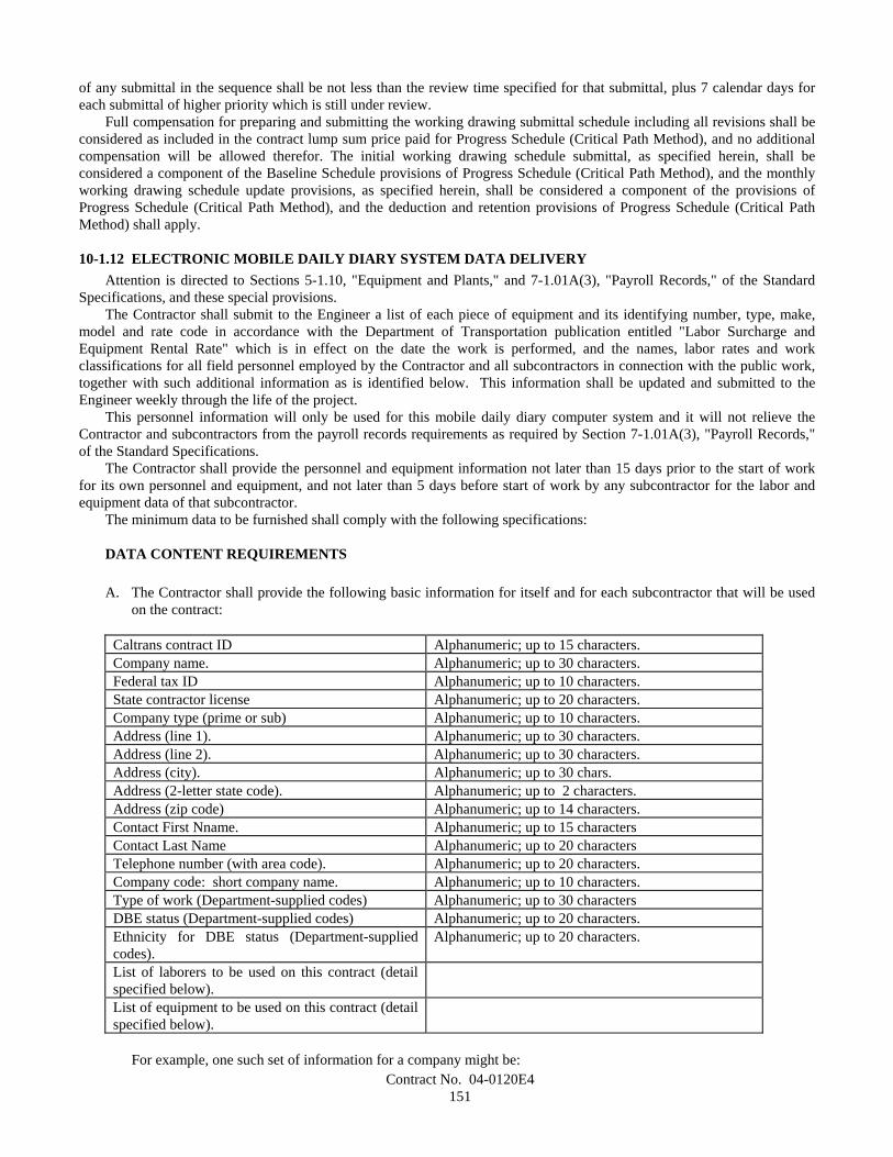
Contract No. 04-0120E4151
of any submittal in the sequence shall be not less than the review time specified for that submittal, plus 7 calendar days foreach submittal of higher priority which is still under review.
Full compensation for preparing and submitting the working drawing submittal schedule including all revisions shall beconsidered as included in the contract lump sum price paid for Progress Schedule (Critical Path Method), and no additionalcompensation will be allowed therefor. The initial working drawing schedule submittal, as specified herein, shall beconsidered a component of the Baseline Schedule provisions of Progress Schedule (Critical Path Method), and the monthlyworking drawing schedule update provisions, as specified herein, shall be considered a component of the provisions ofProgress Schedule (Critical Path Method), and the deduction and retention provisions of Progress Schedule (Critical PathMethod) shall apply.
10-1.12 ELECTRONIC MOBILE DAILY DIARY SYSTEM DATA DELIVERYAttention is directed to Sections 5-1.10, "Equipment and Plants," and 7-1.01A(3), "Payroll Records," of the Standard
Specifications, and these special provisions.The Contractor shall submit to the Engineer a list of each piece of equipment and its identifying number, type, make,
model and rate code in accordance with the Department of Transportation publication entitled "Labor Surcharge andEquipment Rental Rate" which is in effect on the date the work is performed, and the names, labor rates and workclassifications for all field personnel employed by the Contractor and all subcontractors in connection with the public work,together with such additional information as is identified below. This information shall be updated and submitted to theEngineer weekly through the life of the project.
This personnel information will only be used for this mobile daily diary computer system and it will not relieve theContractor and subcontractors from the payroll records requirements as required by Section 7-1.01A(3), "Payroll Records,"of the Standard Specifications.
The Contractor shall provide the personnel and equipment information not later than 15 days prior to the start of workfor its own personnel and equipment, and not later than 5 days before start of work by any subcontractor for the labor andequipment data of that subcontractor.
The minimum data to be furnished shall comply with the following specifications:
DATA CONTENT REQUIREMENTS
A. The Contractor shall provide the following basic information for itself and for each subcontractor that will be usedon the contract:
Caltrans contract ID Alphanumeric; up to 15 characters.Company name. Alphanumeric; up to 30 characters.Federal tax ID Alphanumeric; up to 10 characters.State contractor license Alphanumeric; up to 20 characters.Company type (prime or sub) Alphanumeric; up to 10 characters.Address (line 1). Alphanumeric; up to 30 characters.Address (line 2). Alphanumeric; up to 30 characters.Address (city). Alphanumeric; up to 30 chars.Address (2-letter state code). Alphanumeric; up to 2 characters.Address (zip code) Alphanumeric; up to 14 characters.Contact First Nname. Alphanumeric; up to 15 charactersContact Last Name Alphanumeric; up to 20 charactersTelephone number (with area code). Alphanumeric; up to 20 characters.Company code: short company name. Alphanumeric; up to 10 characters.Type of work (Department-supplied codes) Alphanumeric; up to 30 charactersDBE status (Department-supplied codes) Alphanumeric; up to 20 characters.Ethnicity for DBE status (Department-suppliedcodes).
Alphanumeric; up to 20 characters.
List of laborers to be used on this contract (detailspecified below).List of equipment to be used on this contract (detailspecified below).
For example, one such set of information for a company might be:

Contract No. 04-0120E4152
04-072359XYZ CONSTRUCTION, INC.94-2991040AL1649TSUB1240 9TH STREETSUITE 600OAKLANDCA94612JOHNSMITH(510) 834-9999XYZPAVINGMBEBLACK
B. The Contractor shall provide the following information for each laborer who will be used on the contract:
Caltrans contract ID Alphanumeric; up to 15 characters.Company code (as defined above). Alphanumeric; up to 10 characters.Employee ID Alphanumeric; up to 10 characters.Last name. Alphanumeric; up to 20 characters.First name. Alphanumeric; up to 15 characters.Middle name. Alphanumeric; up to 15 characters.Suffix Alphanumeric; up to 15 charactersLabor trade (Department-provided codes). Alphanumeric; up to 10 characters.Labor classification (Department-provided codes). Alphanumeric; up to 10 characters.Regular hourly rate. Alphanumeric; up to (6,2)Overtime hourly rate. Alphanumeric; up to (6,2)Doubletime hourly rate Alphanumeric; up to (6,2)Standby hourly rate. Alphanumeric; up to (6,2)Ethnicity (Department-provided codes). Alphanumeric; up to 20 characters.Gender. Alphanumeric; up to 1 characters.
For example, one such set of information might be:04-072359XYZ1249GONZALEZHECTORVINCENTJR.OPRJNY12.5018.7525.000.00HISPANICM
C. The Contractor shall provide the following information for each piece of equipment that will be used on thecontract:
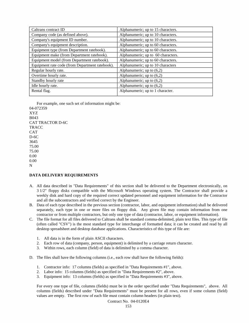
Contract No. 04-0120E4153
Caltrans contract ID Alphanumeric; up to 15 characters.Company code (as defined above). Alphanumeric; up to 10 characters.Company's equipment ID number. Alphanumeric; up to 10 characters.Company's equipment description. Alphanumeric; up to 60 characters.Equipment type (from Department ratebook). Alphanumeric; up to 60 characters.Equipment make (from Department ratebook). Alphanumeric; up to 60 characters.Equipment model (from Department ratebook). Alphanumeric; up to 60 characters.Equipment rate code (from Department ratebook). Alphanumeric; up to 10 charactersRegular hourly rate. Alphanumeric; up to (6,2)Overtime hourly rate. Alphanumeric; up to (6,2)Standby hourly rate Alphanumeric; up to (6,2)Idle hourly rate. Alphanumeric; up to (6,2)Rental flag. Alphanumeric; up to 1 character.
For example, one such set of information might be:04-072359XYZB043CAT TRACTOR D-6CTRACCCATD-6C364575.0075.000.000.00N
DATA DELIVERY REQUIREMENTS
A. All data described in "Data Requirements" of this section shall be delivered to the Department electronically, on3 1/2" floppy disks compatible with the Microsoft Windows operating system. The Contractor shall provide aweekly disk and hard copy of the required correct updated personnel and equipment information for the Contractorand all the subcontractors and verified correct by the Engineer.
B. Data of each type described in the previous section (contractor, labor, and equipment information) shall be deliveredseparately, each type in one or more files on floppy disk. Any given file may contain information from onecontractor or from multiple contractors, but only one type of data (contractor, labor, or equipment information).
C. The file format for all files delivered to Caltrans shall be standard comma-delimited, plain text files. This type of file(often called "CSV") is the most standard type for interchange of formatted data; it can be created and read by alldesktop spreadsheet and desktop database applications. Characteristics of this type of file are:
1. All data is in the form of plain ASCII characters.2. Each row of data (company, person, equipment) is delimited by a carriage return character.3. Within rows, each column (field) of data is delimited by a comma character.
D. The files shall have the following columns (i.e., each row shall have the following fields):
1. Contractor info: 17 columns (fields) as specified in "Data Requirements #1", above.2. Labor info: 15 columns (fields) as specified in "Data Requirements #2", above.3. Equipment info: 13 columns (fields) as specified in "Data Requirements #3", above.
For every one type of file, columns (fields) must be in the order specified under "Data Requirements", above. Allcolumns (fields) described under "Data Requirements" must be present for all rows, even if some column (field)values are empty. The first row of each file must contain column headers (in plain text).
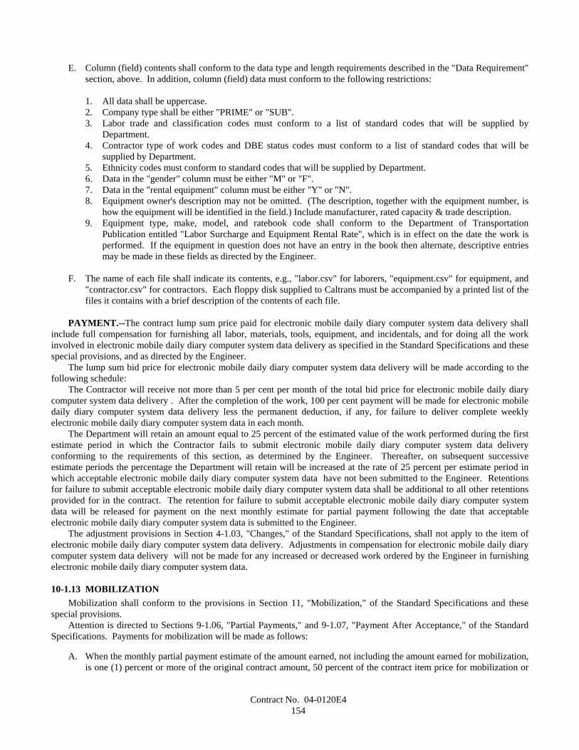
Contract No. 04-0120E4154
E. Column (field) contents shall conform to the data type and length requirements described in the "Data Requirement"section, above. In addition, column (field) data must conform to the following restrictions:
1. All data shall be uppercase.2. Company type shall be either "PRIME" or "SUB".3. Labor trade and classification codes must conform to a list of standard codes that will be supplied by
Department.4. Contractor type of work codes and DBE status codes must conform to a list of standard codes that will be
supplied by Department.5. Ethnicity codes must conform to standard codes that will be supplied by Department.6. Data in the "gender" column must be either "M" or "F".7. Data in the "rental equipment" column must be either "Y" or "N".8. Equipment owner's description may not be omitted. (The description, together with the equipment number, is
how the equipment will be identified in the field.) Include manufacturer, rated capacity & trade description.9. Equipment type, make, model, and ratebook code shall conform to the Department of Transportation
Publication entitled "Labor Surcharge and Equipment Rental Rate", which is in effect on the date the work isperformed. If the equipment in question does not have an entry in the book then alternate, descriptive entriesmay be made in these fields as directed by the Engineer.
F. The name of each file shall indicate its contents, e.g., "labor.csv" for laborers, "equipment.csv" for equipment, and"contractor.csv" for contractors. Each floppy disk supplied to Caltrans must be accompanied by a printed list of thefiles it contains with a brief description of the contents of each file.
PAYMENT.--The contract lump sum price paid for electronic mobile daily diary computer system data delivery shallinclude full compensation for furnishing all labor, materials, tools, equipment, and incidentals, and for doing all the workinvolved in electronic mobile daily diary computer system data delivery as specified in the Standard Specifications and thesespecial provisions, and as directed by the Engineer.
The lump sum bid price for electronic mobile daily diary computer system data delivery will be made according to thefollowing schedule:
The Contractor will receive not more than 5 per cent per month of the total bid price for electronic mobile daily diarycomputer system data delivery . After the completion of the work, 100 per cent payment will be made for electronic mobiledaily diary computer system data delivery less the permanent deduction, if any, for failure to deliver complete weeklyelectronic mobile daily diary computer system data in each month.
The Department will retain an amount equal to 25 percent of the estimated value of the work performed during the firstestimate period in which the Contractor fails to submit electronic mobile daily diary computer system data deliveryconforming to the requirements of this section, as determined by the Engineer. Thereafter, on subsequent successiveestimate periods the percentage the Department will retain will be increased at the rate of 25 percent per estimate period inwhich acceptable electronic mobile daily diary computer system data have not been submitted to the Engineer. Retentionsfor failure to submit acceptable electronic mobile daily diary computer system data shall be additional to all other retentionsprovided for in the contract. The retention for failure to submit acceptable electronic mobile daily diary computer systemdata will be released for payment on the next monthly estimate for partial payment following the date that acceptableelectronic mobile daily diary computer system data is submitted to the Engineer.
The adjustment provisions in Section 4-1.03, "Changes," of the Standard Specifications, shall not apply to the item ofelectronic mobile daily diary computer system data delivery. Adjustments in compensation for electronic mobile daily diarycomputer system data delivery will not be made for any increased or decreased work ordered by the Engineer in furnishingelectronic mobile daily diary computer system data.
10-1.13 MOBILIZATIONMobilization shall conform to the provisions in Section 11, "Mobilization," of the Standard Specifications and these
special provisions.Attention is directed to Sections 9-1.06, "Partial Payments," and 9-1.07, "Payment After Acceptance," of the Standard
Specifications. Payments for mobilization will be made as follows:
A. When the monthly partial payment estimate of the amount earned, not including the amount earned for mobilization,is one (1) percent or more of the original contract amount, 50 percent of the contract item price for mobilization or
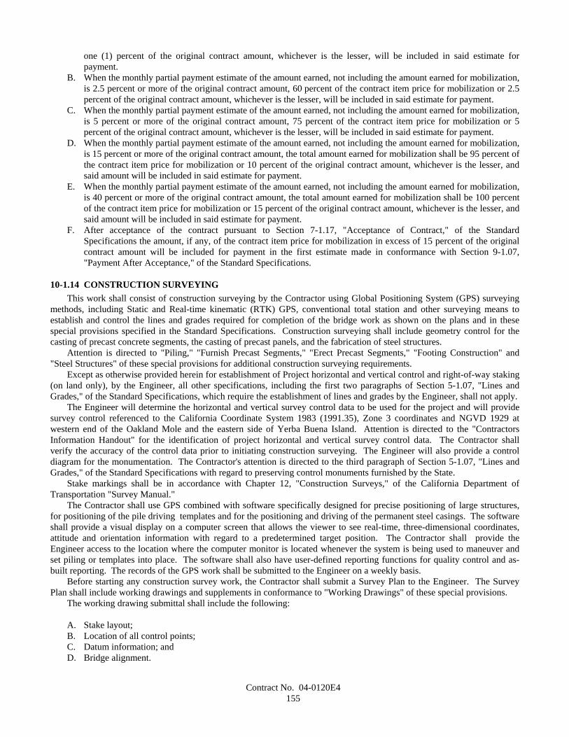
Contract No. 04-0120E4155
one (1) percent of the original contract amount, whichever is the lesser, will be included in said estimate forpayment.
B. When the monthly partial payment estimate of the amount earned, not including the amount earned for mobilization,is 2.5 percent or more of the original contract amount, 60 percent of the contract item price for mobilization or 2.5percent of the original contract amount, whichever is the lesser, will be included in said estimate for payment.
C. When the monthly partial payment estimate of the amount earned, not including the amount earned for mobilization,is 5 percent or more of the original contract amount, 75 percent of the contract item price for mobilization or 5percent of the original contract amount, whichever is the lesser, will be included in said estimate for payment.
D. When the monthly partial payment estimate of the amount earned, not including the amount earned for mobilization,is 15 percent or more of the original contract amount, the total amount earned for mobilization shall be 95 percent ofthe contract item price for mobilization or 10 percent of the original contract amount, whichever is the lesser, andsaid amount will be included in said estimate for payment.
E. When the monthly partial payment estimate of the amount earned, not including the amount earned for mobilization,is 40 percent or more of the original contract amount, the total amount earned for mobilization shall be 100 percentof the contract item price for mobilization or 15 percent of the original contract amount, whichever is the lesser, andsaid amount will be included in said estimate for payment.
F. After acceptance of the contract pursuant to Section 7-1.17, "Acceptance of Contract," of the StandardSpecifications the amount, if any, of the contract item price for mobilization in excess of 15 percent of the originalcontract amount will be included for payment in the first estimate made in conformance with Section 9-1.07,"Payment After Acceptance," of the Standard Specifications.
10-1.14 CONSTRUCTION SURVEYINGThis work shall consist of construction surveying by the Contractor using Global Positioning System (GPS) surveying
methods, including Static and Real-time kinematic (RTK) GPS, conventional total station and other surveying means toestablish and control the lines and grades required for completion of the bridge work as shown on the plans and in thesespecial provisions specified in the Standard Specifications. Construction surveying shall include geometry control for thecasting of precast concrete segments, the casting of precast panels, and the fabrication of steel structures.
Attention is directed to "Piling," "Furnish Precast Segments," "Erect Precast Segments," "Footing Construction" and"Steel Structures" of these special provisions for additional construction surveying requirements.
Except as otherwise provided herein for establishment of Project horizontal and vertical control and right-of-way staking(on land only), by the Engineer, all other specifications, including the first two paragraphs of Section 5-1.07, "Lines andGrades," of the Standard Specifications, which require the establishment of lines and grades by the Engineer, shall not apply.
The Engineer will determine the horizontal and vertical survey control data to be used for the project and will providesurvey control referenced to the California Coordinate System 1983 (1991.35), Zone 3 coordinates and NGVD 1929 atwestern end of the Oakland Mole and the eastern side of Yerba Buena Island. Attention is directed to the "ContractorsInformation Handout" for the identification of project horizontal and vertical survey control data. The Contractor shallverify the accuracy of the control data prior to initiating construction surveying. The Engineer will also provide a controldiagram for the monumentation. The Contractor's attention is directed to the third paragraph of Section 5-1.07, "Lines andGrades," of the Standard Specifications with regard to preserving control monuments furnished by the State.
Stake markings shall be in accordance with Chapter 12, "Construction Surveys," of the California Department ofTransportation "Survey Manual."
The Contractor shall use GPS combined with software specifically designed for precise positioning of large structures,for positioning of the pile driving templates and for the positioning and driving of the permanent steel casings. The softwareshall provide a visual display on a computer screen that allows the viewer to see real-time, three-dimensional coordinates,attitude and orientation information with regard to a predetermined target position. The Contractor shall provide theEngineer access to the location where the computer monitor is located whenever the system is being used to maneuver andset piling or templates into place. The software shall also have user-defined reporting functions for quality control and as-built reporting. The records of the GPS work shall be submitted to the Engineer on a weekly basis.
Before starting any construction survey work, the Contractor shall submit a Survey Plan to the Engineer. The SurveyPlan shall include working drawings and supplements in conformance to "Working Drawings" of these special provisions.
The working drawing submittal shall include the following:
A. Stake layout;B. Location of all control points;C. Datum information; andD. Bridge alignment.
Contract No. 04-0120E4156
The supplement to the working drawing shall show the Contractor's proposed methods of construction surveying and aquality control plan for surveying, and shall include the following:
A. A detailed narrative of the step-by-step surveying control process;B. A listing of the types of methods and the related item(s) to be constructed;C. Detailed calculation forms, and a set of calculation for each type of survey method, including sample input and
output of computer programs;D. Identifications of all measuring equipment, procedures;E. Qualifications of personnel who will carry out construction surveying, and for the Land Surveyor of record; andF. Correlation between the data from geometry control for furnishing precast concrete segments and furnishing steel
structures with data for erection and final line and grade.
Prior to submitting the Survey Plan, the Contractor and any entity performing surveying for this project shall hold a pre-survey meeting with the Engineer to the proposed procedures. The pre-survey meeting shall be held within theSan Francisco Bay Area.
The Contractor shall allow 21 working days for the Engineer to review the Survey Plan after a complete plan has beensubmitted. If revisions are required, as determined by the Engineer, the Contractor shall revise and resubmit the Survey Plan.The Contractors shall allow 14 working days for the Engineer to review the revisions. No construction surveying shallbegan until the Engineer approves the written proposal.
The Contractor shall make the calculations necessary to establish the exact position of the work from the Project controlpoints. Calculations, survey notes computer output, and other construction survey notes and records shall be neat, legible,and accurate. Copies of the survey calculations, notes and other records shall be submitted to the Engineer on a weeklybasis.
The Survey Plan, and the calculations, survey notes and other records submitted to establish the exact position of thework shall be completed under the direction of and signed by a Land Surveyor who is licensed by the State of California.
The Contractor shall submit to the Engineer, a schedule of values detailing the cost breakdown of the contract lump sumitem for construction surveying. The schedule of values shall reflect the items, work, quantities and costs required to do thesurveying required by these special provisions, including surveying for geometry control during precast segmental bridgeconstruction, for the installation of piling and in the erection of steel structures. The Contractor shall be responsible for theaccuracy of the quantities and costs used in the schedule of values submitted for approval.
The sum of the amounts for the items and work listed in the schedule of values shall be equal to the contract lump sumprice for construction surveying. Changes in the schedule of values, due to changes by the Contractor in the items and worklisted, shall not result in a change in the contract lump sum price for construction surveying.
The schedule of values will be used only to determine progress payments for construction surveying during the progressof the work. No payment for construction surveying will be made until the schedule of values is approved in writing by theEngineer.
PAYMENTThe contract lump sum price paid for construction surveying shall include full compensation for furnishing all labor,
materials, tools, equipment, and incidentals, and for doing all the required survey work involved in constructing the newbridge, including surveying for lines and grades, and for geometry control as specified in the these special provisions, and asdirected by the Engineer.
10-1.15 CONSTRUCTION AREA TRAFFIC CONTROL DEVICESFlagging, signs, and all other traffic control devices furnished, installed, maintained, and removed when no longer
required shall conform to the provisions in Section 12, "Construction Area Traffic Control Devices," of the StandardSpecifications and these special provisions.
Category 1 traffic control devices are defined as those devices that are small and lightweight (less than 45 kg), and havebeen in common use for many years. The devices shall be known to be crashworthy by crash testing, crash testing of similardevices, or years of demonstrable safe performance. Category 1 traffic control devices include traffic cones, plastic drums,portable delineators, and channelizers.
If requested by the Engineer, the Contractor shall provide written self-certification for crashworthiness of Category 1traffic control devices. Self-certification shall be provided by the manufacturer or Contractor and shall include thefollowing: date, Federal Aid number (if applicable), expenditure authorization, district, county, route and kilometer post ofproject limits; company name of certifying vendor, street address, city, state and zip code; printed name, signature and title ofcertifying person; and an indication of which Category 1 traffic control devices will be used on the project. The Contractormay obtain a standard form for self-certification from the Engineer.
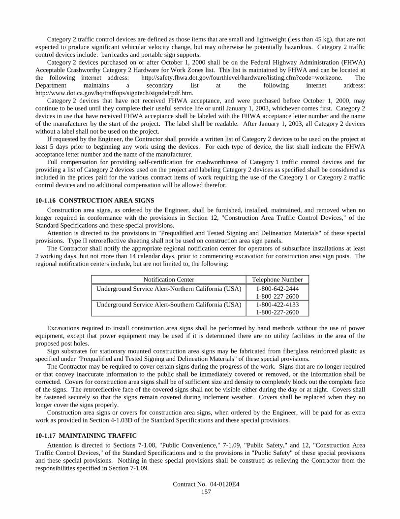
Contract No. 04-0120E4157
Category 2 traffic control devices are defined as those items that are small and lightweight (less than 45 kg), that are notexpected to produce significant vehicular velocity change, but may otherwise be potentially hazardous. Category 2 trafficcontrol devices include: barricades and portable sign supports.
Category 2 devices purchased on or after October 1, 2000 shall be on the Federal Highway Administration (FHWA)Acceptable Crashworthy Category 2 Hardware for Work Zones list. This list is maintained by FHWA and can be located atthe following internet address: http://safety.fhwa.dot.gov/fourthlevel/hardware/listing.cfm?code=workzone. TheDepartment maintains a secondary list at the following internet address:http://www.dot.ca.gov/hq/traffops/signtech/signdel/pdf.htm.
Category 2 devices that have not received FHWA acceptance, and were purchased before October 1, 2000, maycontinue to be used until they complete their useful service life or until January 1, 2003, whichever comes first. Category 2devices in use that have received FHWA acceptance shall be labeled with the FHWA acceptance letter number and the nameof the manufacturer by the start of the project. The label shall be readable. After January 1, 2003, all Category 2 deviceswithout a label shall not be used on the project.
If requested by the Engineer, the Contractor shall provide a written list of Category 2 devices to be used on the project atleast 5 days prior to beginning any work using the devices. For each type of device, the list shall indicate the FHWAacceptance letter number and the name of the manufacturer.
Full compensation for providing self-certification for crashworthiness of Category 1 traffic control devices and forproviding a list of Category 2 devices used on the project and labeling Category 2 devices as specified shall be considered asincluded in the prices paid for the various contract items of work requiring the use of the Category 1 or Category 2 trafficcontrol devices and no additional compensation will be allowed therefor.
10-1.16 CONSTRUCTION AREA SIGNSConstruction area signs, as ordered by the Engineer, shall be furnished, installed, maintained, and removed when no
longer required in conformance with the provisions in Section 12, "Construction Area Traffic Control Devices," of theStandard Specifications and these special provisions.
Attention is directed to the provisions in "Prequalified and Tested Signing and Delineation Materials" of these specialprovisions. Type II retroreflective sheeting shall not be used on construction area sign panels.
The Contractor shall notify the appropriate regional notification center for operators of subsurface installations at least2 working days, but not more than 14 calendar days, prior to commencing excavation for construction area sign posts. Theregional notification centers include, but are not limited to, the following:
Notification Center Telephone NumberUnderground Service Alert-Northern California (USA) 1-800-642-2444
1-800-227-2600Underground Service Alert-Southern California (USA) 1-800-422-4133
1-800-227-2600
Excavations required to install construction area signs shall be performed by hand methods without the use of powerequipment, except that power equipment may be used if it is determined there are no utility facilities in the area of theproposed post holes.
Sign substrates for stationary mounted construction area signs may be fabricated from fiberglass reinforced plastic asspecified under "Prequalified and Tested Signing and Delineation Materials" of these special provisions.
The Contractor may be required to cover certain signs during the progress of the work. Signs that are no longer requiredor that convey inaccurate information to the public shall be immediately covered or removed, or the information shall becorrected. Covers for construction area signs shall be of sufficient size and density to completely block out the complete faceof the signs. The retroreflective face of the covered signs shall not be visible either during the day or at night. Covers shallbe fastened securely so that the signs remain covered during inclement weather. Covers shall be replaced when they nolonger cover the signs properly.
Construction area signs or covers for construction area signs, when ordered by the Engineer, will be paid for as extrawork as provided in Section 4-1.03D of the Standard Specifications and these special provisions.
10-1.17 MAINTAINING TRAFFICAttention is directed to Sections 7-1.08, "Public Convenience," 7-1.09, "Public Safety," and 12, "Construction Area
Traffic Control Devices," of the Standard Specifications and to the provisions in "Public Safety" of these special provisionsand these special provisions. Nothing in these special provisions shall be construed as relieving the Contractor from theresponsibilities specified in Section 7-1.09.
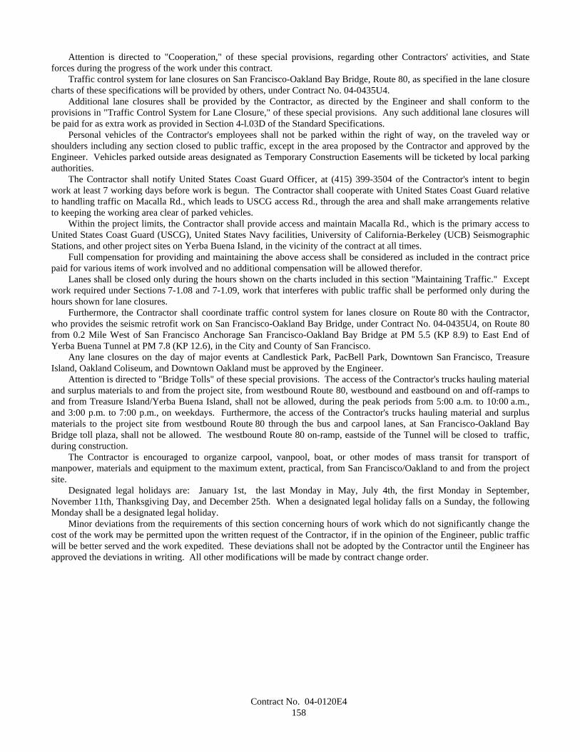
Contract No. 04-0120E4158
Attention is directed to "Cooperation," of these special provisions, regarding other Contractors' activities, and Stateforces during the progress of the work under this contract.
Traffic control system for lane closures on San Francisco-Oakland Bay Bridge, Route 80, as specified in the lane closurecharts of these specifications will be provided by others, under Contract No. 04-0435U4.
Additional lane closures shall be provided by the Contractor, as directed by the Engineer and shall conform to theprovisions in "Traffic Control System for Lane Closure," of these special provisions. Any such additional lane closures willbe paid for as extra work as provided in Section 4-l.03D of the Standard Specifications.
Personal vehicles of the Contractor's employees shall not be parked within the right of way, on the traveled way orshoulders including any section closed to public traffic, except in the area proposed by the Contractor and approved by theEngineer. Vehicles parked outside areas designated as Temporary Construction Easements will be ticketed by local parkingauthorities.
The Contractor shall notify United States Coast Guard Officer, at (415) 399-3504 of the Contractor's intent to beginwork at least 7 working days before work is begun. The Contractor shall cooperate with United States Coast Guard relativeto handling traffic on Macalla Rd., which leads to USCG access Rd., through the area and shall make arrangements relativeto keeping the working area clear of parked vehicles.
Within the project limits, the Contractor shall provide access and maintain Macalla Rd., which is the primary access toUnited States Coast Guard (USCG), United States Navy facilities, University of California-Berkeley (UCB) SeismographicStations, and other project sites on Yerba Buena Island, in the vicinity of the contract at all times.
Full compensation for providing and maintaining the above access shall be considered as included in the contract pricepaid for various items of work involved and no additional compensation will be allowed therefor.
Lanes shall be closed only during the hours shown on the charts included in this section "Maintaining Traffic." Exceptwork required under Sections 7-1.08 and 7-1.09, work that interferes with public traffic shall be performed only during thehours shown for lane closures.
Furthermore, the Contractor shall coordinate traffic control system for lanes closure on Route 80 with the Contractor,who provides the seismic retrofit work on San Francisco-Oakland Bay Bridge, under Contract No. 04-0435U4, on Route 80from 0.2 Mile West of San Francisco Anchorage San Francisco-Oakland Bay Bridge at PM 5.5 (KP 8.9) to East End ofYerba Buena Tunnel at PM 7.8 (KP 12.6), in the City and County of San Francisco.
Any lane closures on the day of major events at Candlestick Park, PacBell Park, Downtown San Francisco, TreasureIsland, Oakland Coliseum, and Downtown Oakland must be approved by the Engineer.
Attention is directed to "Bridge Tolls" of these special provisions. The access of the Contractor's trucks hauling materialand surplus materials to and from the project site, from westbound Route 80, westbound and eastbound on and off-ramps toand from Treasure Island/Yerba Buena Island, shall not be allowed, during the peak periods from 5:00 a.m. to 10:00 a.m.,and 3:00 p.m. to 7:00 p.m., on weekdays. Furthermore, the access of the Contractor's trucks hauling material and surplusmaterials to the project site from westbound Route 80 through the bus and carpool lanes, at San Francisco-Oakland BayBridge toll plaza, shall not be allowed. The westbound Route 80 on-ramp, eastside of the Tunnel will be closed to traffic,during construction.
The Contractor is encouraged to organize carpool, vanpool, boat, or other modes of mass transit for transport ofmanpower, materials and equipment to the maximum extent, practical, from San Francisco/Oakland to and from the projectsite.
Designated legal holidays are: January 1st, the last Monday in May, July 4th, the first Monday in September,November 11th, Thanksgiving Day, and December 25th. When a designated legal holiday falls on a Sunday, the followingMonday shall be a designated legal holiday.
Minor deviations from the requirements of this section concerning hours of work which do not significantly change thecost of the work may be permitted upon the written request of the Contractor, if in the opinion of the Engineer, public trafficwill be better served and the work expedited. These deviations shall not be adopted by the Contractor until the Engineer hasapproved the deviations in writing. All other modifications will be made by contract change order.
Contract No. 04-0120E4159
Chart No. 1Multilane Lane Requirements
Location: Eastbound Route 80, between eastbound off-ramp (Lt) KP 12.4 and Southgate Road
a.m. p.m.FROM HOUR TO HOUR 12 1 2 3 4 5 6 7 8 9 10 11 12 1 2 3 4 5 6 7 8 9 10 11 12Mondays through Thursdays 1 1 1 1 1 1 1 1
Fridays 1 1 1 1 1 1 1Saturdays 1 1 1 1 1 1 1 1 1Sundays 1 1 1 1 1 1 1 1 1 1 1 1
Day before designated legal holiday 1 1 1 1 1 1 1Designated legal holidays 1 1 1 1 1 1 1 1 1 1 1 1
Legend:1 One lane may be closed in direction of travel
No lane closure allowed
REMARKS:
Chart No. 2Multilane Lane Requirements
Location: Westbound Route 80, between Southgate Road and westbound on-ramp (Rt) at KP 12.3
a.m. p.m.FROM HOUR TO HOUR 12 1 2 3 4 5 6 7 8 9 10 11 12 1 2 3 4 5 6 7 8 9 10 11 12Mondays through Thursdays 1 1 1 1 1 1 1 1 1
Fridays 1 1 1 1 1 1 1 1Saturdays 1 1 1 1 1 1 1 1 1Sundays 1 1 1 1 1 1 1 1 1 1 1 1
Day before designated legal holiday 1 1 1 1 1 1 1 1Designated legal holidays 1 1 1 1 1 1 1 1 1 1 1 1
Legend:1 One lane may be closed in direction of travel
No lane closure allowed
REMARKS:
10-1.18 CLOSURE REQUIREMENTS AND CONDITIONSLane closures shall conform to the provisions in "Maintaining Traffic" of these special provisions and these special
provisions.The Engineer will have the authority to disapprove any closure schedule request, deny or abort any closure on any
portion of the traveled way, when deemed necessary for the safe and efficient operation of public traffic or when necessaryto resolve conflicts in closure schedules' among Contractors or other State forces performing work within the State right ofway.
The term closure, as used herein, is defined as the closure of a traffic lane or lanes, including ramp or connector lanes,within a single traffic control system.
Contract No. 04-0120E4160
CLOSURE SCHEDULEBy noon Monday, the Contractor shall submit a written schedule of planned closures for the following week period,
defined as Friday noon through the following Friday noon.The Closure Schedule shall show the locations and times when the proposed closures are to be in effect. The Contractor
shall use the Closure Schedule request forms furnished by the Engineer. Closure Schedules submitted to the Engineer withincomplete, unintelligible or inaccurate information will be returned for correction and resubmittal. The Contractor will benotified of disapproved closures or closures that require coordination with other parties as a condition of approval.
Amendments to the Closure Schedule, including adding additional closures, shall be submitted to the Engineer, inwriting, at least 3 working days in advance of a planned closure. Approval of amendments to the Closure Schedule will be atthe discretion of the Engineer.
The Contractor shall confirm, in writing, all scheduled closures by no later than 8:00 a.m. 3 working days prior to thedate on which the closure is to be made. Approval or denial of scheduled closures will be made no later than 4:00 p.m. 2working days prior to the date on which the closure is to be made. Closures not confirmed or approved will not be allowed.
Confirmed closures that are cancelled due to unsuitable weather may be rescheduled at the discretion of the Engineer forthe following working day.
CONTINGENCY PLAN The Contractor shall prepare a contingency plan for reopening closures to public traffic. The Contractor shall submit
the contingency plan for a given operation to the Engineer within one working day of the Engineer's request.
LATE REOPENING OF CLOSURESIf a closure is not reopened to public traffic by the specified time, work shall be suspended in conformance with the
provisions in Section 8-1.05, "Temporary Suspension of Work," of the Standard Specifications. The Contractor shall notmake any further closures until the Engineer has accepted a work plan, submitted by the Contractor, that will insure thatfuture closures will be reopened to public traffic at the specified time. The Engineer will have 2 working days to accept orreject the Contractor's proposed work plan. The Contractor will not be entitled to any compensation for the suspension ofwork resulting from the late reopening of closures.
For each 10-minute interval, or fraction thereof past the time specified to reopen the closure, the Department will deduct$8,500 per interval from moneys due or that may become due the Contractor under the contract.
COMPENSATIONThe Contractor shall notify the Engineer of any delay in the Contractor's operations due to the following conditions, and
if, in the opinion of the Engineer, the Contractor's controlling operation is delayed or interfered with by reason of thoseconditions, and the Contractor's loss due to that delay could not have been avoided by rescheduling the affected closure or byjudicious handling of forces, equipment and plant, the delay will be considered a right of way delay within the meaning ofSection 8-1.09, "Right of Way Delays," and compensation for the delay will be determined in conformance with theprovisions in Section 8-1.09:
A. The Contractor's proposed Closure Schedule is denied and his planned closures are within the time frame allowedfor closures in "Maintaining Traffic" of these special provisions, except that the Contractor will not be entitled toany compensation for amendments to the Closure Schedule that are not approved.
B. The Contractor is denied a confirmed closure.
Should the Engineer direct the Contractor to remove a closure prior to the time designated in the approved ClosureSchedule, any delay to the Contractor's schedule due to removal of the closure will be considered a right of way delay withinthe meaning of Section 8-1.09, "Right of Way Delays," and compensation for the delay will be determined in conformancewith the provisions in Section 8-1.09.
10-1.19 TRAFFIC CONTROL SYSTEM FOR LANE CLOSUREA traffic control system shall consist of closing traffic lanes in conformance with the details shown on the plans, the
provisions in Section 12, "Construction Area Traffic Control Devices," of the Standard Specifications, the provisions under"Maintaining Traffic" and "Construction Area Signs" of these special provisions, and these special provisions.
The provisions in this section will not relieve the Contractor from the responsibility to provide additional devices or takemeasures as may be necessary to comply with the provisions in Section 7-1.09, "Public Safety," of the StandardSpecifications.
Contract No. 04-0120E4161
The traffic control required for work on the bridge deck of San Francisco-Oakland Bay Bridge within the limits of thiscontract will be provided only by another State contractor. Attention is directed to "Maintaining Traffic" and "ClosureRequirements and Conditions" elsewhere in these special provisions.
Attention is directed to "Cooperation," of these special provisions, regarding other Contractors' activities, and Stateforces during the progress of the work under this contract. Maintenance work by State forces shall be permitted where suchwork will not impact the Contractor's operations or when emergency work by State forces is required. The Contractor shallcoordinate his operations with maintenance forces and other contractors performing work within the contract limits of thiscontract. If the provided freeway lane closure is not used by the Contractor for the approved scheduled work for laneclosure, the cost for providing a freeway lane closure will be deducted from the money due to the Contractor.
The Contractor shall coordinate the lane closure schedule with the State contractor providing the traffic control at theSan Francisco-Oakland Bay Bridge. The Contractor shall be responsible for all costs incurred to other contractors and Stateforces in the event that the work for this contract is not finished as scheduled and the lane closures cannot be removed per theapproved closure schedule.
All access to the work from either the upper or lower deck of the bridge, which may be contemplated by the Contractor,will be subject to coordination with other contracts, which may be in progress during this contract. The determination ofwhich of the lanes will be closed for access to the work will be made in accordance with these special provision, subsections"Closure Requirements and Conditions".
Each vehicle used to place, maintain and remove components of a traffic control system on multilane highways shall beequipped with a Type II flashing arrow sign which shall be in operation when the vehicle is being used for placing,maintaining or removing components. Vehicles equipped with Type II flashing arrow sign not involved in placing,maintaining or removing components when operated within a stationary lane closure shall only display the caution displaymode. The sign shall be controllable by the operator of the vehicle while the vehicle is in motion. The flashing arrow signshown on the plans shall not be used on vehicles which are being used to place, maintain and remove components of a trafficcontrol system and shall be in place before a lane closure requiring its use is completed.
If components in the traffic control system are displaced or cease to operate or function as specified, from any cause,during the progress of the work, the Contractor shall immediately repair the components to the original condition or replacethe components and shall restore the components to the original location.
When lane closures are made for work periods only, at the end of each work period, components of the traffic controlsystem, except portable delineators placed along open trenches or excavation adjacent to the traveled way, shall be removedfrom the traveled way and shoulder. If the Contractor so elects, the components may be stored at selected central locationsdesignated by the Engineer within the limits of the highway right of way.
Full compensation for conforming with these provisions shall be considered as included in the contract prices paid forthe various items of work and no separate payment will be made therefor.
Traffic control system required by work which is classed as extra work, as provided in Section 4-1.03D of the StandardSpecifications, will be paid for as a part of the extra work.
10-1.20 TEMPORARY CRASH CUSHION MODULEThis work shall consist of furnishing, installing, and maintaining sand filled temporary crash cushion modules in
groupings or arrays at each location shown on the plans, as specified in these special provisions or where designated by theEngineer. The grouping or array of sand filled modules shall form a complete sand filled temporary crash cushion inconformance with the details shown on the plans and these special provisions.
Attention is directed to "Public Safety", "Order of Work", and "Temporary Railing" of these special provisions.Whenever the work or the Contractor's operations establishes a fixed obstacle, the exposed fixed obstacle shall be
protected with a sand filled temporary crash cushion. The sand filled temporary crash cushion shall be in place prior toopening the lanes adjacent to the fixed obstacle to public traffic.
Sand filled temporary crash cushions shall be maintained in place at each location, including times when work is notactively in progress. Sand filled temporary crash cushions may be removed during a work period for access to the workprovided that the exposed fixed obstacle is 4.6 m or more from a lane carrying public traffic and the temporary crash cushionis reset to protect the obstacle prior to the end of the work period in which the fixed obstacle was exposed. When no longerrequired, as determined by the Engineer, sand filled temporary crash cushions shall be removed from the site of the work.
At the Contractor's option, the modules for use in sand filled temporary crash cushions shall be either Energite IIIInertial Modules, Fitch Inertial Modules or TrafFix Sand Barrels manufactured after March 31, 1997, or equal:
A. Energite III and Fitch Inertial Modules, manufactured by Energy Absorption Systems,Inc., One East Wacker Drive, Chicago, IL 60601-2076. Telephone 1-312-467-6750,FAX 1-800-770-6755
Contract No. 04-0120E4162
1. Distributor (North): Traffic Control Service, Inc., 8585 Thys Court, Sacramento,CA 95828. Telephone 1-800-884-8274, FAX 1-916-387-9734
2. Distributor (South): Traffic Control Service, Inc., 1881 Betmor Lane, Anaheim,CA 92805. Telephone 1-800-222-8274, FAX 1-714-937-1070
B. TrafFix Sand Barrels, manufactured by TrafFix Devices, Inc., 220 Calle Pintoresco,San Clemente, CA 92672. Telephone 1-949 361-5663, FAX 1-949 361-9205
1. Distributor (North): United Rentals, Inc., 1533 Berger Drive, San Jose, CA 95112.Telephone 1-408 287-4303, FAX 1-408 287-1929
2. Distributor (South): Statewide Safety & Sign, Inc., P.O. Box 1440, Pismo Beach,CA 93448. Telephone 1-800-559-7080, FAX 1-805 929-5786
Modules contained in each temporary crash cushion shall be of the same type at each location. The color of the modulesshall be the standard yellow color, as furnished by the vendor, with black lids. The modules shall exhibit good workmanshipfree from structural flaws and objectionable surface defects. The modules need not be new. Good used undamaged modulesconforming to color and quality of the types specified herein may be utilized. If used Fitch modules requiring a seal arefurnished, the top edge of the seal shall be securely fastened to the wall of the module by a continuous strip of heavy dutytape.
Modules shall be filled with sand in conformance with the manufacturer's directions, and to the sand capacity inkilograms for each module shown on the plans. Sand for filling the modules shall be clean washed concrete sand ofcommercial quality. At the time of placing in the modules, the sand shall contain not more than 7 percent water asdetermined by California Test 226.
Modules damaged due to the Contractor's operations shall be repaired immediately by the Contractor at the Contractor'sexpense. Modules damaged beyond repair, as determined by the Engineer, due to the Contractor's operations shall beremoved and replaced by the Contractor at the Contractor's expense.
Temporary crash cushion modules shall be placed on movable pallets or frames conforming to the dimensions shown onthe plans. The pallets or frames shall provide a full bearing base beneath the modules. The modules and supporting palletsor frames shall not be moved by sliding or skidding along the pavement or bridge deck.
A Type R or P marker panel shall be attached to the front of the crash cushion as shown on the plans, when the closestpoint of the crash cushion array is within 3.6 m of the traveled way. The marker panel, when required, shall be firmlyfastened to the crash cushion with commercial quality hardware or by other methods determined by the Engineer.
At the completion of the project, temporary crash cushion modules, sand filling, pallets or frames, and marker panelsshall become the property of the Contractor and shall be removed from the site of the work. Temporary crash cushionmodules shall not be installed in the permanent work.
Temporary crash cushion modules placed in conformance with the provisions in "Public Safety" of these specialprovisions will not be measured nor paid for.
10-1.21 EXISTING HIGHWAY FACILITIESThe work performed in connection with various existing highway facilities shall conform to the provisions in
Section 15, "Existing Highway Facilities," of the Standard Specifications and these special provisions.Attention is directed to "Project Information," of these special provisions, regarding underwater debris. Underwater
debris, within the project limits, at the bottom of the bay, has been mapped and is shown in "Phase I Archaeological SurveyReport - Maritime Archaeology", and "Addendum Archaeological Survey Report - Maritime Archaeology."
Full compensation for removal of underwater debris (shown in said report) that is in conflict with construction workshown shall be considered to be included in the various types of work involved, and no additional compensation will beallowed therefor.
10-1.22 EARTHWORKEarthwork shall conform to the provisions in Section 19, "Earthwork," of the Standard Specifications and these special
provisions.
TOWER OVERSIZED HOLESTower oversized holes shall consist of drilling oversized holes at each pile for Pier 1 to the limits and elevations shown
on the plans.Oversized hole diameter shall be at least 400 mm greater than the outside diameter of the permanent steel casing.Tower oversized holes shall be to within 150 mm of the elevation shown on the plans.
Contract No. 04-0120E4163
All drilling shall be performed within a sealed temporary casing to ensure that all drilling fluid cuttings return to at leastElev. +3 m NGVD for separation and disposal.
Blasting will not be permitted to create the tower pile oversized hole.Attention is directed to "Dredging," of these special provisions regarding handling of materials resulting from the
drilling of tower oversized holes, and removing and disposing of material resulting from cleaning out the steel shells piles.The Contractor shall submit working drawings for drilling tower oversized holes in accordance with "Working
Drawings," of these special provisions. Working drawings shall contain sufficient detail to show the Contractor's methods ofperforming drilling and shall include, at a minimum, the following:
A. Site preparation prior to hole drilling.B. Equipment proposed.C. Methods of removing surplus material from the site.D. Inspection methods and monitoring.E. Controlling elevations.F. Grade control.G. Contingency plans in case of hole collapse.H. Procedure for the removal of the temporary drilling casing.
At the option of the Contractor, significantly oversized holes may be constructed to facilitate removal of temporarycasing.
ISOLATION MATERIALThe permanent steel casings at the tower foundation shall be outfitted with a layer of isolation material around the piles
between the limits in elevation shown on the plans.The intent of the isolation material is to provide a compressible layer between the pile and surrounding rock, so that the
pile is free to move laterally during an earthquake without excessive resistance. Possible materials include; closed cellpolyurethane, polystyrene, and similar materials.
The isolation material shall be a minimum of 100 mm thick under atmospheric pressure and shall have the followingproperties.
A. Maximum deformation of 10% of original thickness under maximum hydrostatic pressure (including a possiblegrout head of 9 m with a specific gravity of 2.5.
B. Compressive strength of 750 kPa to 1000 kPa at a deformation of 100 mm.C. The material shall be insoluble, non-poisonous and stable under water.
The isolation material shall be attached to the pile surface with a waterproof adhesive that is compatible with theisolation material, unless approved otherwise by the Engineer. The attachment system shall ensure that under the hydrostatichead described above the isolation material remains intact and in place.
The Contractor shall submit working drawings for isolation material, and its attachment, in accordance with "WorkingDrawings," of these special provisions. Working drawings shall contain sufficient detail to indicate the Contractor's methodsof applying and protecting the isolation material and shall include, at a minimum, the following:
A. Isolation material proposed for useB. Adhesive proposed for useC. Methods of applying and protecting isolation material (fabric, or other)D. Inspection methods and monitoring.E. Test results verifying compression characteristics and compatibility of adhesive with epoxy coating and isolation
material.
FOUNDATION TOLERANCESThe foundations shall be installed at the locations shown on the plans with the associated elevations and orientations.The following tolerances shall be achieved. These tolerances are absolute and not additive.All assembly tolerances shall be measured from the pile sleeve theoretical locations.Piles at the Pier T1 and Pier E2 foundations shall be installed within the pile sleeves so as to provide a minimum grout
thickness of 75 mm.
Contract No. 04-0120E4164
Tower FoundationThe tower foundation steel frame shall conform to the following tolerances:
A. During fabrication of the steel frame and piles, API RP2A "Recommended Practice for Planning, Designing andConstructing Fixed Offshore Platforms – Working Stress Design" 20th Edition shall apply.
The foundation steel frame shall be installed in the location shown on the plans within the following tolerances:
A. Horizontal location: +/- 25 mm radially measured at the geometric center.B. Elevation +3.000 m: +/- 25 mm measured at the geometric center.C. Level: +/- 15 mm at the top plate adjacent to any pile sleeve.D. Orientation (in plan): +/- 25 mm at the extreme pile sleeves.
Pier E2 FoundationThe Pier E2 foundation shall conform to the following tolerances:
During fabrication of the steel frame and piles, API RP2A "Recommended Practice for Planning, Designing andConstructing Fixed Offshore Platforms – Working Stress Design" 20th Edition shall apply. Fabrication of the tie-beams shallconform to the requirements of AISC and AWS D1.5, as appropriate.
The foundation steel frame shall be installed in the location shown on the plans within the following tolerances:
A. Station and offset: +/- 50 mm radially measured at the geometric center.B. Elevation +3.000 m: +/- 50 mm measured at the geometric center.C. Level: +/- 25 mm at the top plate adjacent to any pile sleeve.D. Orientation (in plan): +/- 50 mm at the extreme pile sleeves.
PAYMENTAttention is directed to "Piling," of these special provisions for payment for oversize holes and isolation material.
10-1.23 DREDGINGDredging shall include removal and disposal of marine sediment resulting from the drilling of tower oversized holes, and
removing; disposing of material resulting from cast-in-steel-shell concrete piling, cast-in-drilled-hole concrete piling; andfrom temporary structures, over-excavation, and maintenance; and shall be considered dredging under the terms of thevarious permits obtained by the Department.
Attention is directed to "Permits And Licenses" and "Environmental Work Restrictions" of these special provisions.Attention is directed to "Turbidity Control" of these special provisions for turbidity control requirements for all
dredging.Removal of materials resulting from the drilling of tower oversized holes, and removing and disposing of material
resulting from cast-in-steel-shell and cast-in-drilled-hole concrete piling, shall conform to the provisions in "Piling" of thesespecial provisions.
Over-excavation may be allowed if deemed necessary to complete the work, however no additional compensation shallbe allowed therefor. Lateral displacement of dredged material will not be allowed. Maintenance dredging to reach orpreserve final grade shall be at the Contractor's expense. Dredging shall be done in accordance with the provisions of thevarious permits obtained by the Department. All dredged material shall be disposed of according to the permit requirementsand these special provisions.
Dredging Operations Plan: The Contractor shall submit a Dredging Operations Plan (DOP) 60 calendar days prior tothe proposed commencement of dredging. Dredging shall not commence until all comments have been addressed andwritten approval has been granted by the Army Corps of Engineers and the Engineer. The DOP shall include the following:
A. Name and telephone number of the dredging Contractor's representatives on site;B. Army Corp of Engineers permit number;C. Dredging start and completion dates;D. Schedule of dredging operations including sequence of work, anticipated quantities and production rates;E. Name(s) of vessels;F. Numbers or identification for all equipment;
Contract No. 04-0120E4165
G. Bin or barge capacities;H. Identification and purpose of work;I. Proposed dredging procedures, including types of equipment to be used, method of slurry of the material with
detailed drawings or specifications of the grid or centrifugal pump system;J. Quality of material to be removed;K. Overall location of the area authorized to be dredged;L. A vicinity map showing the proposed upland disposal sites;M. Proposed volume of material to be dredged and disposed;N. Dredging design depth based on 1929 National Geodetic Vertical Datum (NGVD) and typical cross section
including overdepth; andO. Date of last dredging operations and design depth.
The DOP shall also provide the following information:
A. The controls being established to ensure that dredging operations occur at the locations shown on the plans and asspecified in these special provisions.
B. The controls being established to ensure that disposal of the dredged material at the disposal sites is at the assignedlocation and depth and the horizontal and vertical positioning systems that will be utilized.
C. Method of determining horizontal and vertical electronic positioning of dredge or dump scow during entiredredging operation at dredge site, disposal site and en route to and from disposal site.
D. Contractor's Dredging Quality Control Plan (DQCP ) including:
1. A description of the DQCP organization including, a chart showing lines of authority; and acknowledgmentthat the Contractor quality control staff shall conduct the inspections for all aspects of the work specified andshall report to the Contractor's Project Manager, or someone of higher authority, in the Contractor'sorganization;
2. The name, qualifications, duties, responsibilities and authorities of each person assigned a quality controlfunction;
3. A copy of the letter to the DQCP manager; signed by an authorizing official of the firm, which describes theresponsibilities and delegates the authorities of the DQCP manager; shall be furnished to the DQCP managerand shall be countersigned by the DQCP manager acknowledging receipt; and
4. Reporting procedures and methods used to obtain information for quality control forms, including the submittalof displacement and capacity charts for all scows.
After acceptance of the DOP, the Contractor shall notify the Engineer in writing of any proposed changes. Proposedchanges are subject to acceptance by the Engineer.
Dredging Time Restriction: Approval to dredge in open water from November 15 to March 31 of any year will onlybe allowed as follows:
A. The dredging operation was begun prior to November 15 of any year and could not be completed by the November15 deadline due to unforeseen delays;
B. A biologist provided by the State will monitor for the presence of herring spawns within 200 meters of constructionoperations in open water and will be at the project site during dredging operations which occur between November15 through March 31; and
C. Dredging operations within 200 meters of spawn shall cease within eight hours of notification by the Engineer for aminimum of 14 days or until the Engineer notifies the Contractor that dredging may be resumed.
Hydraulic dredging in open water at elevations of 6 meters or less below Mean Lower Low Water will not be allowedfrom January 1 to May 31 of any year.
Solid Debris Management Plan: The Contractor shall submit a Solid Debris Management plan 60 calendar days priorto commencement of dredging. The plan shall describe measures to ensure that solid debris generated during any dredgingoperation is retained and properly disposed of. At a minimum the plan shall include the following:
A. Source and expected type of debris;B. Debris retrieval method;

Contract No. 04-0120E4166
C. Disposal method and site;D. Schedule of disposal operations; andE. Debris containment method to be used, if floatable debris is involved.
All such debris shall become the property of the Contractor and shall be disposed of outside the State's right of way inaccordance with Section 7-1.13 of the Standard Specifications. No such material shall be disposed of within the jurisdictionsof the Army Corps of Engineers and Bay Conservation and Development Commission. Material deemed to be of historicalsignificance as determined by the Engineer shall become the property of the State.
Overflow: No overflow of dredged material or water will be allowed from the receiving barges, bins or dump scowsduring the dredging operations except for spillage incidental to clamshell dredging operations.
Spillage and Leakage: Dredged material and water shall not be permitted to spill over or leak out of barges or dumpscows while in transit to the disposal site. The Contractor shall record draft of hull for each scow load as specified underquality control. No loss in draft or volume will be permitted from containers transporting dredged materials for landdisposal. The Contractor shall paint visible draft levels at 0.3 meter intervals and at the 80 percent load line on the inside ofeach scow.
Overflow and Leakage Monitoring Requirements: The Contractor shall provide equipment that will furnish acontinuous printed record of readings and measurements of bulk density and mass flow rate for each pump. These recordsshall be provided to the Engineer as requested and approved in the Dredging Operation Plan. The Contractor shall provide alist of equipment that will provide the required records. In the event either velocity or displacement equipment breaks downduring the dredging operation, the following actions shall be accomplished:
A. An alternative means of measurement shall be performed as approved; andB. Alternative measurements shall not exceed duration of 72 hours after the equipment breakdown. Verification of
repairs shall be provided to the Engineer in the form of receipts or other documentation.
For clamshell dredges, the Contractor shall monitor hull displacement of each scow loaded by the dredge. For hydraulicdredges the Contractor shall provide equipment that will furnish a continuous printed record of readings for measurement offlow rate of the material within 6 meters of the dredge pump, and furnish a continuous printed record of readings formeasurement of flow rate of the material within 6 meters of the discharge manifold. The Contractor shall also furnishcontinuous velocity records at booster pumps. Equipment shall be accessible from above water platforms. If the readingsfrom the velocity flow equipment indicate leakage within the system, the Contractor shall immediately cease work and repairthe leaks. In the event that the dredged material is pumped into a barge or scow, displacement shall be monitored asspecified for clamshell dredges after dredging and before disposal at the disposal site. The Contractor shall furnish to theEngineer, displacement and capacity plans of all scows. Monitoring for clamshell and hydraulic dredges shall be continuousfrom initial loading through discharge at the disposal site. The Contractor may use the general configuration in these specialprovisions for developing a system of monitoring displacement or submit an alternative method for approval. The methodshall provide average hull displacement of each scow as specified. The data recorders shall store two-minute averages of theone second input signals from the sensors. The Contractor shall provide and maintain throughout the duration of thecontract, one data transfer unit with support software to the State within 30 Calendar days after award of the contract, whichshall become State property upon completion of the contract. In the event the displacement monitoring equipment breaksdown during the dredging operation for any of the scows, an alternative means of measurement shall be performed andresults reported using a form. Alternative measurements shall not exceed duration of 72 hours after equipment breakdown.If repairs to the primary equipment are not accomplished within this period, the scow shall not be used until repaired.
The Contractor shall submit the continuous recording records specified for clamshell dredge reports to the Engineerelectronically. All data shall be recorded in ASCII text. Any alternatives submitted by the Contractor shall be subject to theapproval of the Engineer.
Control and Monitoring Surveys: A short to medium range Electronic Positioning System (EPS) or GlobalPositioning System (GPS) shall be provided on all vessels involved in dredging operations. The EPS shall be established,operated and maintained by the Contractor during the period of the contract when dredging work is actively underway. TheEPS using range-range methods shall display and record the vessel's location continuously during dredging and transport fordisposal. A continuous graphic printout plotter and/or graphic monitor shall be provided on any dredge utilizing a range-range positioning system and a complete record copy of the position data (dredge track history) including date, time,coordinates and Root Mean Square (quality of position closure); and such record shall be submitted to the Engineer as part of
Contract No. 04-0120E4167
the daily report. The Engineer shall have access to the monitoring equipment in order to observe its operation during thedredging work.
The EPS system shall be similar or equal in design, performance, accuracy, operating characteristics, and frequency tothose identified in "Hydrographic Surveying" Department of the Army Engineering Manual No. 1110-2-1003, 28 February1991 (or latest version). This manual is available for purchase at:
USACE Publications Depot2803 52nd AvenueHyattsville, MD 20781-1102
or may be reviewed at the Army Corps of Engineers Construction-Operations Division, San Francisco District Office,333 Market Street, San Francisco, California.
The Contractor shall be responsible for establishing the horizontal control to locate active or passive shore-based EPStransmitter/receiver devices. All control shall meet Third Order, Class 1, accuracy standards as defined in the publication"Standards and Specifications for Geodetic Control Networks" published by the Federal Geodetic Control Committee (andreferenced) under chapter 2 of the Army Corps of Engineers Manual "Hydrographic Surveying". The Contractor shall obtainall right-of-entry permits and/or leases as required to operate and maintain shore-based electronic equipment onpublic/private property.
EPS calibration techniques shall conform to standard hydrographic surveying practice; consistent with minimization ofsystematic errors inherent to, and consistent with, the selected EPS system as specified under Chapter 6 of the Army Corps ofEngineers manual "Hydrographic Surveying". The Contractor shall be responsible for accurate and reliable EPS calibrationfor the duration of this contract.
Transport and Disposal: The Contractor shall transport and dispose of the dredged material in accordance with thesespecial provisions and the conditions of the various permits the State has obtained for this contract.
During transport to the disposal sites, no material shall be permitted to overflow, spill, or leak out of the barges, bins ordump scows.
Tugboats are required to use an electronic positioning system (i.e., a miniranger system with at least two transponders ora Global Positioning System (GPS) with a minimum accuracy and precision of 8 meters for disposal operations). If thepositioning system fails, all disposal operations shall cease until the navigational capabilities are restored.
The Contractor shall maintain daily records of dredging operations, transportation schedules, barge load volumesdisposed, and exact location and time of disposal.
The tug captain shall maintain a copy of all weather reports and shall make wind and sea observations.The Contractor shall observe all dredging operations and submit reports containing; a description of operations for each
barge load, a checklist, a transit route map, a printout of coordinates from each way point and release point, a record of radiotransmission, and facsimile from the tug captain on a daily basis.
The Contractor shall allow observers from the State and other appropriate independent observers as specified in permitsand approved by the Engineer to be present on disposal vessels on trips to the disposal areas.
Development and implementation of a more sophisticated surveillance systems, which can be demonstrated to andapproved by the Engineer to be effective and capable of being audited, may be substituted for one or more of the aboveprovisions.
The Electronic Positioning System (EPS) and methods used for the dredge, as specified herein, shall also be used todisplay and record the disposal vessel's location at one minute time intervals.
All of the above-mentioned documentation shall be submitted to the Engineer after each transportation and disposalevent.
Air Quality Requirements: If the work is performed by clamshell or hydraulic dredge, the Contractor shall beresponsible for compliance with all BAAQMD regulations and standards including obtaining a permit for operation of astationary source of air pollutants. A copy of the permit shall be included with the quality control plan. If applicable, at theContractor-furnished land disposal site(s), the Contractor will be required to obtain any necessary air quality permits foroperation of pumps and equipment. Copies of the permits shall be included with the quality control plan.
Unless "optimized" or diesel powered equipment with the "Best Available Control Technology" emission devices areused, injection timing on diesel powered dredges and equipment shall be retarded two degrees from manufacturer'srecommended setting to reduce air pollutant emissions.
Reformulated diesel fuel shall be used for all diesel-powered dredges and equipment to reduce air pollutant emissions.Reformulated diesel fuel shall be a low sulfur, reduced aromatics diesel fuel meeting the following specifications, unlessotherwise approved by the Engineer:

Contract No. 04-0120E4168
A. Sulfur content less than 0.05 percent by weight; andB. Aromatic content less than 20 percent by volume. Prior to dredging or construction operations, the Contractor shall
submit certification from the fuel supplier or manufacturer stating that the fuel contents meet the aboverequirements and proof of purchase of the above-specified fuel shall be submitted to the Engineer. Dredges andequipment shall not be allowed to idle when not required in performing the work. Dredges and equipment shall begiven a tune-up at least annually.
Radiological Safety: If the Contractor intends to use any radiological source on the project, such use shall be reportedby letter to the Engineer. The letter shall state the type of radioactive material in the source, serial number of the equipment,manufacturer, licensee, and the purpose for which the equipment will be used. A copy of the last safety certification(s) fromthe appropriate 01430-3 Federal and State agencies shall be included with the letter. No radiological materials shall bestored, handled or used on this contract without the prior approval of the Engineer. The storage, handling and use ofradioactive materials shall comply with the pertinent State and Federal (EM 385-1-1) safety regulations.
Landfill Disposal: Landfill disposal shall be provided by the Contractor for the following dredged material:
A. Material in contact with synthetic slurry used in pile operations;B. Material resulting from test boring operations; andC. Material that does not pass through a debris grid as specified.
In-Bay (Aquatic) Disposal: The Alcatraz Dredged Material Disposal Site (SF-11) is not available for disposal ofdredged material from this project because the permitted disposal allocation has been met by other contracts.
Ocean (Aquatic) Disposal: The San Francisco Deep Ocean Disposal Site is not available for disposal of dredgedmaterial from this project because the permitted disposal allocation has been met by other contracts.
Other Upland Disposal Sites: Land disposal sites for the dredged material not listed in "Landfill Disposal" of thisSection consisting of clay, silt, or sand may be approved by the Engineer in conformance with the provisions in Section7-1.13, "Disposal of Material Outside the Highway Right of Way," of the Standard Specifications.
Contractor–Furnished Land or Aquatic Disposal Sites: The Contractor may propose to use alternative aquatic orland disposal site for disposing dredged material intended to be disposed at Alcatraz or the SF-DODS. If an aquatic or landdisposal site is proposed, its acceptance will be based on receipt of written evidence from the Contractor stating that theowner's written consent for use of such area has been obtained; that the proposed area has been coordinated with theapplicable Federal, State and local agencies; and that all permits have been obtained for use of such sites.
The Contractor shall also submit to the Engineer for approval a plan for the disposal site, which covers, as a minimum,impounding levees and weir structures, pipeline leakage and repair, and effluent weirs and spillways. All expenses incurredin connection with providing and making available such disposal site shall be borne by the Contractor, and all materialsdeposited thereon, and all operations in connection therewith shall be at the Contractor's risk. EPS monitoring of landdisposal operations will not be required.
Combination State and Contractor-Furnished Disposal Sites: The use of both State and Contractor-furnisheddisposal sites will be allowed. The Contractor may propose to utilize all or a portion of the State-furnished disposal sites.The acceptance of such proposal will be subject to the approval of the Engineer.
Disposal Site Verification Log (DSVL): The Contractor shall submit a weekly log by 10:00 a.m. each Monday to theEngineer. The DSVL sheets attached to the Army Corps of Engineers Permit (Pages 1 & 2) shall be used to enumerate thework accomplished during the preceding week for submission to the Army Corps of Engineers, Regulatory Branch. TheVessel Traffic Control System will issue a confirmation number, which shall be included in the weekly log. If the DSVL isnot submitted on Monday by 10:00 a.m., no work shall begin on the dredging operations for that week.
Hydrographic Surveys: In the event that open-water dredging is required to complete the work, the followingprovisions for surveys shall apply. The Contractor shall be responsible for providing an independent surveyor to perform thepre-and post-dredging and quality control surveys for performing the related computations and furnishing the requireddrawings.
Contract No. 04-0120E4169
The independent surveyor's equipment and work force shall be independent from the Contractor. The name of thesurveyor and samples of previous hydrographic work shall be submitted to the Engineer for review and approval.
The Engineer shall be allowed to board all watercraft performing the hydrographic surveys.The independent surveyor shall be required to document and certify in writing to the Engineer that he has at least three
years of experience in hydrographic surveying of navigable channels and possess either a current land surveyor's orprofessional engineer's license valid in California and American Congress on Surveying and Mapping (ACSM) certificationas an "Inshore Certified Hydrographic Surveyor." He shall provide documentation that modern electronic horizontalpositioning and depth finding equipment are available for the surveys to be performed including Differential GlobalPositioning System (DGPS) capability and shall include as a minimum; the name, model, and year of manufacture of theelectronic equipment; the electronic frequencies of the horizontal positioning equipment and the depth finding equipment;and the manufacturer's stated positioning accuracy and capability of the equipment proposed for usage. In addition, he shalldocument availability of a safe and suitable workboat for operation in the water where the surveys are to be performed, andthat experienced staff are available for the operation of the workboat as well as the operation and calibration of the electronicpositioning and depth finding equipment calibration. Survey procedures, data collection equipment, methods and densities,and equipment calibration for this work shall follow the criteria given in the hydrographic survey manual specified in thisSection for a Class I hydrographic survey. Survey line spacing shall not exceed the limits given in Table 3-1 of thehydrographic survey manual for a Class I hydrographic survey. Survey lines shall be referenced to the project horizontal andvertical datum. Cross sections shall be run at 10 meters center to center (c/c) and shall extend 10 meters past the slope-original ground intersect point.
The Contractor's hydrographic survey procedures (positioning modes, EPS calibration, accuracy requirements, depthmeasurement/calibration, and data reduction, adjustment, processing, and plotting) shall conform to industry standardsidentified in the hydrographic survey manual specified elsewhere in these special provisions. Horizontal locationobservations shall compensate for errors, geodetic corrections, and atmospheric variations. Data recordation, annotation, andprocessing procedures shall be in accordance with the hydrographic survey manual specified elsewhere. Failure to performand process such surveys in accordance with the manual and these specifications will result in rejection and nonpayment forwork performed. All vertical control shall be of second order accuracy, including levels for the setting of tide gage toNGVD elevation. An automatic electronic tide recording system shall be required during all surveying and dredgingoperations.
Survey data shall include tidal cycle(s) (whether ebb, flood or slack tide conditions) while performing surveys.The Contractor shall conduct surveys using electronic system positioning method in accordance with the Hydrographic
Survey Manual. The Contractor shall use an echo sounder to obtain soundings. The analog recording of soundings shallindicate a calibration check (bar check) of the echo sounding at the beginning and end of each analog paper change and atsuch times as necessary to ensure sounding accuracy. Echo sounder shall have a frequency of 200 kHz, with 3.5 degreescone measured at 6-dB point. The top of the return signal trace shall be the point of interpretation of sounding. The barcheck shall be taken at identical locations. Soundings shall be on NGVD datum. The excavation centerlines and slope toesshall be field marked on the fathogram chart during the data acquisition. The contract station, time of survey, tide height anddirection that line is surveyed shall also be marked on the fathograms. Annotated survey data shall include tidal cycle(s), i.e.,slack or slack tide conditions are occurring while performing surveys.
Field notes shall indicate the location of each sounding line, the date and the time (hour and minutes) each sounding linewas taken and explanation for any line terminated early. The tide shall be recorded for each line surveyed and noted on thesections during the survey. Notes shall include tidal data, i.e., height of tide (Mean Lower Low Water Datum), bar checks,time of the tide readings and date and location of the tide gage used for each survey.
Bound field survey books shall be used to record all field data. Fully automated survey systems shall require a field logto supplement the data recorded on magnetic media.
The cross sections of hydrographic sounding line survey results shall be plotted at the scales specified in Table 3-1 ofthe Hydrographic Survey Manual. Soundings shall be plotted on transparent sheets and show pay quantity excavationtemplates shown on the plans with survey cross-section. The Contractor's firm name shall be printed on each sheet alongwith contract name, number and date of survey. Plot scales shall be as approved by the Engineer.
The Contractor shall perform Pre-Dredging Surveys not earlier than 60 calendar days and not later than 30 calendar daysbefore commencement of dredging. The Pre-Dredging Survey shall be completed with accuracy to within 30 mm whichdelineates the following: areas to be dredged; width overdepth allowances; existing depths; estimated quantities to bedredged for the project; and estimated quantities for overdepth.
The Contractor shall perform hydrographic Quality Control Surveys thirty days after start of dredging and every thirtycalendar days thereafter, and after any natural event that would create shoaling of previously dredged areas of the project(e.g., severe storms and earthquakes). These surveys shall verify that all foundation excavation dimensions are beingobtained as specified. All surveys shall begin where dredging commenced and end as close as possible to last dredgingposition. The accuracy shall be consistent with the Pre-Dredging Survey above.
Contract No. 04-0120E4170
From the Quality Control Surveys, the Contractor shall compute quantities by the average end area method to the nearestcubic meter based on the sounding lines surveyed and the dredging section indicated on the plans. Tabular summaries shallbe submitted to show standard depth, overdepth, and total dredging quantities both incrementally and cumulative for openwater locations.
The Contractor shall perform a Post-Dredging Survey within 15 calendar days of the last disposal activity at each openwater location prior to placing backfill (last being defined as that activity after which no further activity occurs for 15calendar days), a survey with accuracy to one-tenth foot which delineates the following: areas dredged; dredged depths;actual quantities dredged for the project; and actual quantities of overdepth. The Post-Dredging Survey shall contain thedates of commencement and completion. The Contractor shall substantiate the total quantity dredged by includingcalculations used to determine the volume difference (in cubic meters) between the Pre- and Post Dredging Surveys andexplain any variation in quantities greater than 15 percent beyond estimated quantities.
The quantities calculated from pre-dredging, quality control, and post-dredging surveys shall only be used for permitreporting purposes. Quantities from these surveys shall not be used for measurement of quantities for payment.
The Contractor shall submit all drawings, field notes and quantity computations within five calendar days aftercompletion of any survey. The number of sets of drawings shall be as specified below. The Contractor shall mail or deliverdrawings and computations to the Engineer for review and submission to the various agencies:
A. Three sets of transparent drawings for each survey;B. Three sets of computer sheet printouts or calculation sheets for dredging quantities for each survey; andC. Three sets of cross-sections for each survey.
The Contractor shall submit for each survey, the ASCII file of raw and corrected survey data. Data shall be on CD-Rom, operating under MSWindows 2000 or newer version. The files shall have hydrosurvey information, in both raw andadjusted format. The raw data shall be original data from the hydrosurvey computer. The adjusted data shall be corrected toNational Ocean Survey NGVD datum. The record of raw data shall be comma delimited and consist of the followinginformation: index, "x" coordinate; "y" coordinate; "z" elevation; and time. Each adjusted record shall consist of thefollowing information: index; "x" coordinate; "y" coordinate; "z" elevation; time; and tide. The index shall be the first entry,representing the sequence that each point was taken. The index shall be numerical, beginning with the number "one" andcontinuing until a 24 hour work effort is completed. Each day shall be in one file (one or more disks). This convention isapplicable for both raw and adjusted data. Time shall be reported in Gregorian day and military hours and seconds. (Forexample, "17 March 2001, 9:00 a.m." would be "170301, 090000"). The recording distance between the hydrosurvey pointsshall be 3 meters or less. All data recorded shall be in ASCII test. Other data collection formats will be considered ifpresented by the Contractor. Revisions in collection format will not be considered after the project has begun. Allalternatives shall be approved by the Engineer.
The Contractor shall provide a complete listing of hydrographic equipment to be used on the project prior to the surveyconference specified herein below.
At least five calendar days prior to performing any survey, the person responsible for that survey, the Contractor's chiefsurveyor and/or the independent surveyor, shall meet with the Engineer in a survey conference to outline the scope of surveyand section interval. No survey work shall be performed until such conference has taken place.
The Department will retain an amount equal to 5 percent of the estimated value of the associated item of work performedduring each estimate period in which the Contractor fails to complete the hydrographic surveys.
PAYMENTFull compensation for Dredging Operation Plan preparation and updating; preparing and implementing Solid Debris
Management Plan; overflow and leakage monitoring; implementing air quality requirements; performing control andmonitoring surveys; preparation of disposal site verification logs; and performing hydrographic surveys including datacollection and preparation of drawings, cross-sections and calculations shall be considered as included in the contract pricespaid for the items of work involved and no additional compensation will be allowed therefor.
10-1.24 PILING
GENERALPiling shall conform to the provisions in Section 49, "Piling," of the Standard Specifications, and these special
provisions.Foundation information is included in the "Information Handout" available to the Contractor as provided for in
Section 2-1.03, "Examination of Plans, Specifications, Contract, and Site of Work," of the Standard Specifications.
Contract No. 04-0120E4171
Soil samples and rock cores are available for viewing. Contact the Toll Bridge Duty Senior at the office of the TollBridge Duty Senior at the District 4 Office, 111 Grand Avenue, Oakland, CA 94612, email:[email protected], telephone number (510) 286-5209.
Attention is directed to "Nonshrink Grout" and "Nonshrink Fiber Reinforced Grout," of these special provisions forgrouting permanent steel casing at Pier 1 and cast-in-steel shell concrete piling at Pier E2.
Attention is directed to "Strong Motion Detection System," and "Pile Corrosion Monitoring System," of these specialprovisions regarding equipment to be installed in piling.
Attention is directed to "Miscellaneous Metal," of these special provisions regarding steel downhole casing to beinstalled in piling.
Attention is directed to "Sound Control Requirements," of these special provisions.Attention is directed to "Earthwork," of these special provisions regarding oversize holes, foundation tolerances and
isolation material for piles.The requirements in Section 49-1.03, "Determination of Length," of the Standard Specifications shall not apply.Driven piling shall be installed and shall be of such length as required to obtain the specified pile tip elevation and to
extend into the pile cap, as shown on the plans.All steel shells for cast-in-steel-shell piles shall be clearly marked along their entire length in increments of 250 mm with
more prominent markings every meter. Marking shall be made by white paint lines 50 mm wide. Markings shall beaccurately placed on the pile with a tape measure that is at least 30 meters in length such that the intended measurement istrue at the bottom of the marking. Markings shall be visible from all directions and shall indicate cumulative length from thepile toe.
Cast-in-steel-shell pile installation procedures shall consider the presence of soft soils that allow piles to penetratesignificant distances under self-weight and the weight of the hammer, dense soils and bedrock that result in hard driving,soils that gain strength during delays in driving, wind and wave excitation, and tidal flow fluctuation.
Cast-in-drilled-hole concrete pile installation procedures shall consider the presence of soft caving soil, dense soil,embedment in bedrock, wind and wave excitation, and tidal flow fluctuation.
DRIVING EQUIPMENTPile hammer energy input to the pile will be verified by the Engineer using dynamic monitoring.
Primary HammerThe primary hammer shall be defined as a hydraulic impact hammer with a minimum manufacturer's rated energy of
1700 kJ. The Contractor shall maintain the primary hammer at the site and it shall be fully operational at all times duringpile driving operations.
Jetting and drilling in conformance with Section 49-1.05 "Driving Equipment," of the Standard Specifications shall notbe used.
At the option of the Contractor, vibratory hammers may be used to install piling to no deeper than El. –35 metersNGVD.
PILE ALIGNMENT TEMPLATE AND PILE HANDLING SUBMITTALThe Contractor shall provide a pile alignment template to maintain support of the temporary and permanent steel shell,
casings, and reinforcing steel cages during pile installation. Prior to installing piling, the Contractor shall submit to theEngineer for approval in accordance with the provisions in "Working Drawings," of these special provisions, workingdrawings for the pile alignment template and pile handling procedures.
The Contractor shall allow the Engineer 70 working days after complete drawings and all supporting calculations aresubmitted for review of the pile alignment template working drawings.
Pile handling shall conform to the recommendations in API RP2A "Recommended Practice for Planning, Designing, andConstructing Fixed Offshore Platforms."
Working drawings for the pile alignment template and pile handling procedures shall include the following:
A. Details for installation and removal of the pile alignment template.B. Details and equipment used for handling of pile including the use of temporary lifting or handling attachments and
supporting brackets.C. Details and methods for cutting the pile at the specified cut-off elevation and removing the pile head, as applicable.D. A list of all tasks required to install the piles and a written procedure for performing the work.E. Details and equipment associated with maintaining the pile alignment template including cranes and crane vessels,
mooring systems and anchor patterns, transport barges, pile supports and fastenings.
Contract No. 04-0120E4172
Working drawings for the pile alignment template and pile handling procedures shall be supplemented by calculations,and the calculations shall include the following:
A. Details and calculations demonstrating how the pile installation system will provide and maintain the specified axialand radial alignment of the pile to within an angle of 1 in 100 or to a lesser tolerance, if specified elsewhere in thesespecial provisions.
B. Details and calculations demonstrating adequate support and stability for the pile with the full operating weight anddynamic loading of the proposed hammer at the top of the pile as applicable.
C. Provisions to provide stability and maintain alignment during placement of the piles and casings in wind, wave andcurrent conditions.
D. Details and characteristics of any additional temporary alignment devices provided by the Contractor to preventdamage to in-place foundation elements during pile driving.
E. Provisions to prevent a driven pile from running under its own weight and the weight of the hammer, including, at aminimum, provisions to prevent the pile from penetrating below the top of the pile alignment template, steelfoundation frame, as applicable or below water level.
F. Provisions for providing adequate work space for pile welding, cutting and inspection.G. Provisions for ensuring the specified pile straightness, alignment, and support to prevent relative movement during
field welding and to ensure that welding tolerances are met.H. Method and equipment for monitoring pile alignment.I. Calculation of pile stresses and deflections resulting from handling operations.
The temporary pile alignment template shall be removed after the installation of the piling. Any temporary pilingrequired to support the pile alignment template shall be removed to at least 400 mm below original mudline or existingmudline at the time of pile removal, whichever is lower. Procedures for installation and removal of the alignment templateand piles shall be included in the working drawing submittal.
DRIVING PILESPile heads to receive the hammer shall be square and smooth. The pile head face shall be perpendicular to the
longitudinal axis of the pile. The maximum allowable deviation of any point on the pile head surface from a trueperpendicular plane shall be 6 mm. Local deviations from a plane of best fit that are greater than 3 mm shall be groundsmooth.
Pile head steel shell thickness shall be equal to or greater than the steel shell thickness of the pile. Splice weldsassociated with the pile head shall be full penetration welds.
After driving, the outer surface of the pile shall be no closer than 75 mm from the inner surface of the pile sleeve.The Contractor shall survey each pile and record the top of pile location both vertically and horizontally and shall
determine the pile's variance from the true line. Such variance shall be measured in two planes normal to each other. Thetop of pile location shall be surveyed immediately after each pile section is driven complete in place and also before a splicedpile section is driven. A second survey shall be carried out after all piles have been cut to their final elevations.
Pile surveying shall conform to "Construction Surveying," of these special provisions. All pile surveying data shall besubmitted in writing to the Engineer at the completion of pile driving operations for a given work day.
A given pile that is driven to specified penetration and that fails to meet the alignment tolerances specified in this sectionwill be rejected and replaced prior to driving other piles. Alternative corrective measures, if any, are subject to the priorapproval of the Engineer and the cost of alternative measures shall be considered the sole responsibility of the Contractor.
Within 10 working days after the pile has been rejected, and prior to driving other piling, the Contractor shall revise histemporary pile alignment template. The Contractor shall submit to the Engineer for approval a plan for revised pileinstallation methods and this plan shall conform to the provisions in "Working Drawings," of these special provisions.
Revised pile alignment template plans and pile handling shall also include the following:
A. A step by step description of the work to be performed, including revised pile driving alignment template drawingsand handling procedures as necessary.
B. A list of affected details and plan sheets.
The Engineer will notify the Contractor in writing when a complete plan has been received. The Contractor shall allowthe Engineer 15 working days to review the revised pile installation plan after a complete submittal has been received.
PILE DRIVING REFUSALThe requirements in Section 49-1.08, "Bearing Value and Penetration," of the Standard Specifications shall not apply.

Contract No. 04-0120E4173
Pile driving refusal shall be defined as the time when pile driving resistance, using the primary hammer operating at fullrated energy according to the manufacturer's specifications, meets one of the following conditions:
A. 250 blows for each 250 mm over a penetration of 1500 mm; orB. 670 blows for 250 mm of penetration
If pile driving is interrupted for more than one hour, the above definition of refusal shall not apply until the pile has beendriven 250 mm. During restart, or at any time, 670 blows in 125 mm shall be taken as pile driving refusal.
PILE DRIVING LOW RESISTANCEIf extremely low resistance to driving is experienced when driving within one meter of the specified pile tip elevation,
the Engineer may modify the pile details shown on the plans.When the Engineer directs the Contractor to modify the pile details shown on the plans, said work will be paid for as
extra work as provided in Section 4-1.03D, "Extra Work," of the Standard Specifications.
PILE PENETRATION ACCEPTANCEThe requirements in Section 49-1.08, "Bearing Value and Penetration," of the Standard Specifications shall not apply.Pile penetration acceptance shall be based on the following criteria:
A. Piles driven to the specified pile tip will be accepted.B. Piles that encounter refusal during continuous driving within 10 meters of the specified pile tip elevation, will be
accepted.C. Within 10 meters above the specified pile tip elevation, if piles develop toe stresses in excess of 85 percent of the
specified yield strength of the steel shell or pile stresses in excess of 90 percent of the specified yield strength of thesteel shell, as determined by the Engineer, pile driving shall be terminated and the pile will be accepted.
D. For piles that develop stresses in excess of 90 percent of the specified yield strength of the steel shell, as determinedby the Engineer, at an elevation more than 10 meters above the specified pile tip elevation, the Contractor shallreduce the pile hammer stroke and continue driving the pile to the specified pile tip elevation. When pile drivingstresses are excessive and hammer stroke cannot be reduced without encountering refusal, the Contractor shallremove the soil plug and continue driving the piles to the specified pile tip elevation. Soil plug removal shall notextend below an elevation that is 7 meters above the pile toe at the time of refusal.
E. The Contractor shall provide a pile driving log at the completion of driving each pile or pile section. Uponcompletion of pile driving for a given pile, the Contractor shall allow the Engineer 48 hours to review the piledriving records. The Contractor shall not cut the top of the pile until the Engineer's review period is complete.
F. Unless otherwise directed by the Engineer, piles shall be driven continuously below El. –65 meters NGVD. Ifdriving refusal is encountered as a result of delays in pile driving occurring within this zone, the Contractor shall beresponsible for soil plug removal down to an elevation not less than 75 meters above the specified pile tip elevation,splicing the pile (including all weld nondestructive testing) and any other measures necessary to advance the pile.
G. For piles that encounter driving refusal at an elevation more than 10 meters above the specified pile tip elevation,the Contractor shall remove the soil plug and continue driving the piles. The Contractor's equipment andprocedures shall be adequate to complete soil plug removal and resume driving within 48 hours. Soil plug removalshall not extend below an elevation that is 7 meters above the pile toe at the time of refusal.
DRIVING SYSTEM SUBMITTALPrior to installing driven piling , the Contractor shall provide a driving system submittal, including driveability analysis,
in conformance with the provisions in "Working Drawings," of these special provisions. Technical data for all proposeddriving systems (i.e., each hammer that may be brought onto the site) shall be included in the submittal.
The driving system submittal shall contain an analysis showing that the proposed driving systems will install piling tothe specified pile tip elevation without soil plug removal and without overstressing the pile. Submittals shall include thefollowing:
A. Complete description of soil parameters used, including soil quake and damping coefficients, skin frictiondistribution, percentage shaft resistance, and total soil resistance to driving.
B. List of all hammer operation parameters assumed in the analysis, including manufacturer's rated energy, fuelsettings, stroke limitations, and hammer efficiency.
C. Driveability studies that are based on a wave equation analysis using a computer program that has been approved bythe Engineer. Driveability studies shall model the Contractor's proposed driving systems, including the hammers,
Contract No. 04-0120E4174
capblocks, pile cushions, and followers. The analyses shall consider a range of total soil resistance to driving andassociated percentage shaft resistance for plugged and unplugged cases. The range of soil resistance to driving andpercentage shaft resistance shall be determined for site conditions ranging from 10 meters above the specified tipelevation to the specified tip elevation shown on the plans. Separate analyses shall be completed at elevationsabove the specified pile tip elevations where difficult driving or pile splices are anticipated.
Driveability analysis results shall include plots of the following:
1. Maximum pile head and pile toe compressive stress versus blows per 250 mm.2.. Soil resistance to driving versus blows per 250 mm.
D. Details of equipment and procedures for removing the soil plug after successful pile driving and as a contingency inthe case of driving refusal above an acceptable tip elevation.
E. Copies of all test results from any previous pile load tests, dynamic monitoring, and all driving records used in theanalyses.
F. Completed "Pile and Driving Data Form," which is shown in these special provisions.G. Estimated range of expected pile penetration due to self-weight and the weight of the hammer.H. Written procedures for pile driving and a pile installation schedule, including at a minimum, the first and last pile.
The Contractor shall allow the Engineer 35 working days to review each driving system submittal.The Contractor shall use the driving system and installation methods described in the approved driving system submittal
for each pier location. Any change in hammers from those submitted and approved by the Engineer shall also meet therequirements for driving system submittals. Revised and new driving system submittals shall be approved by the Engineerprior to using corresponding driving systems on production piling. The Contractor shall allow the Engineer 35 working daysto review each revised and each new driving system submittal after a complete set has been received, as determined by theEngineer.
Approval of pile driving equipment or installation methods shall not relieve the Contractor of his responsibility to drivepiling free of damage to the specified penetration.
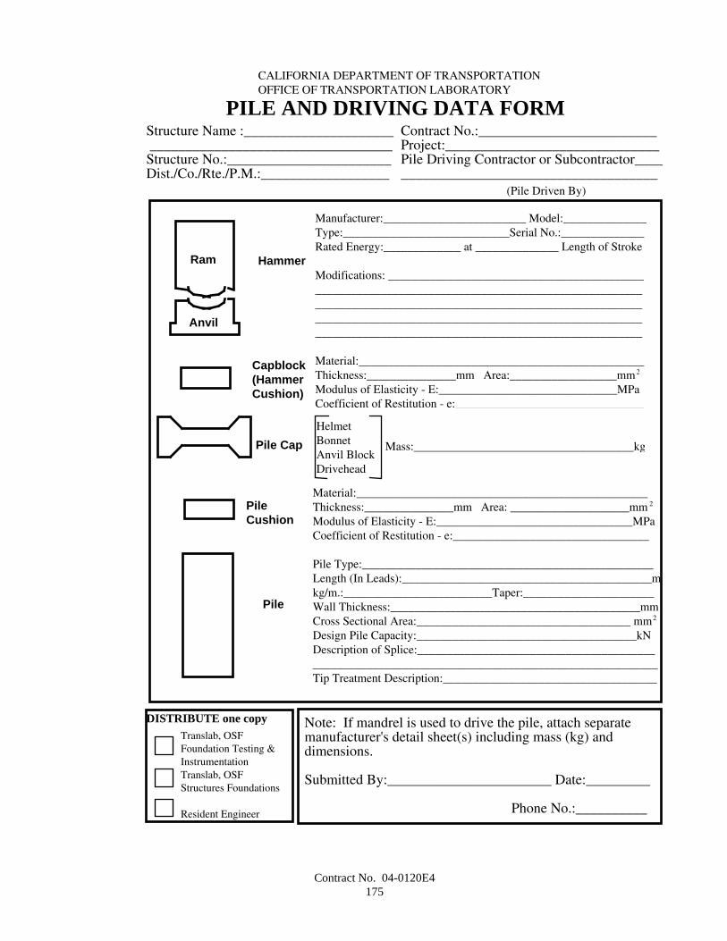
Contract No. 04-0120E4175
HammerRam
Anvil
Manufacturer:________________________ Model:______________Type:____________________________Serial No.:______________Rated Energy:_____________ at ______________ Length of Stroke
Modifications: _______________________________________________________________________________________________________________________________________________________________________________________________________________________________________________________________________
Material:________________________________________________Thickness:_______________mm Area:__________________mm2
Modulus of Elasticity - E:______________________________MPaCoefficient of Restitution - e:________________________________
Capblock(HammerCushion)
Structure Name :_____________________ __________________________________Structure No.:_______________________Dist./Co./Rte./P.M.:__________________
Contract No.:_________________________Project:______________________________Pile Driving Contractor or Subcontractor________________________________________
(Pile Driven By)
CALIFORNIA DEPARTMENT OF TRANSPORTATIONOFFICE OF TRANSPORTATION LABORATORY
PILE AND DRIVING DATA FORM
DISTRIBUTE one copyTranslab, OSFFoundation Testing &InstrumentationTranslab, OSFStructures Foundations
Resident Engineer
Note: If mandrel is used to drive the pile, attach separatemanufacturer's detail sheet(s) including mass (kg) anddimensions.
Submitted By:_______________________ Date:_________
Phone No.:__________
HelmetBonnetAnvil BlockDrivehead
Mass:_____________________________________kgPile Cap
Material:_________________________________________________Thickness:_______________mm Area: ____________________mm 2
Modulus of Elasticity - E:_________________________________MPaCoefficient of Restitution - e:_________________________________
Pile Type:_________________________________________________Length (In Leads):__________________________________________mkg/m.:_________________________Taper:______________________Wall Thickness:__________________________________________mmCross Sectional Area:____________________________________ mm2
Design Pile Capacity:_____________________________________kNDescription of Splice:__________________________________________________________________________________________________Tip Treatment Description:______________________________________________________________________________________________
PileCushion
Pile
Contract No. 04-0120E4176
DYNAMIC MONITORINGUnless otherwise directed by the Engineer, the last 35 meters for each production pile will be monitored during driving
for dynamic response to the driving equipment. Monitoring will be done by State forces using State-furnished dynamic pileanalyzer monitoring instruments.
Monitoring instruments shall be fastened to the piles using the tapped holes shown on the plans.If the Contractor's driving system is such that monitoring instruments will be underwater, the Contractor shall notify the
Engineer, in writing, at least 50 working days prior to commencement of driving operations.The Contractor shall provide electric power (120-volt, 60 cycles stable power) for the State's monitoring equipment,
access to the piles including a working platform, and shelter for State monitoring personnel and equipment.Piles to be dynamically monitored shall be made available to State forces at least 8 hours prior to lifting. The pile shall
be positioned so that State forces have safe access to the top 35 meters of the pile length for the installation of anchoragesand control marks for monitoring. The Contractor shall rotate the piles on the blocks as directed by the Engineer.
Piles to be dynamically monitored shall be prepared and driven in accordance with the following:
A. The Engineer will determine if the Contractor's handling operations during lifting of the pile segment to bemonitored are such that pile monitoring instruments can be bolted to the pile prior to lifting without damage to theinstruments. If the Engineer determines that instruments cannot be mounted prior to lifting of the pile, operationsshall be suspended for approximately 30 minutes before hammer placement. During this time the Contractor shallattach monitoring instruments onto the pile.
B. Prior to resuming driving operations, the Contractor shall connect electrical cables to the instrument package asapproved by the Engineer.
C. Driving operations shall resume as directed by the Engineer. The Contractor's driving equipment shall providesufficient clearances for monitoring instruments such that piles can be driven to the specified pile tip elevationwithout damage to the monitoring instruments.
Within 4 hours of completion of driving operations, the Contractor shall remove the cables and instrument package fromthe pile and deliver them to the Engineer. If monitoring instruments are underwater at the end of driving, the Contractorshall provide a diver and shall retrieve the cables and instruments.
The Contractor shall be responsible for damage to the State's cables and instruments caused by the Contractor'soperations, and shall replace damaged cables or instruments in kind.
CAST-IN-DRILLED-HOLE CONCRETE PILESCast-in-drilled-hole concrete piling shall conform to the provisions in Section 49-4, "Cast-In-Place Concrete Piles," of
the Standard Specifications and these special provisions.Cast-in-drilled-hole concrete piling (rock socket) shall consist of drilling or coring sockets in bedrock to the depths or
lengths shown on the plans and as specified in these special provisions and filling with reinforced concrete in conformancewith the details shown on the plans and these special provisions. Cored holes, if used, shall conform to the provisions ofSection 49-4.03, "Drilled Holes," of the Standard Specifications and these special provisions.
Equipment or methods used for drilling or coring holes shall not result in a smooth hole. Diamond drilling bits will notbe permitted. The surface of drilled holes shall have a roughness of 6 mm full amplitude. Roughness of drilled holes shallbe verified by the Contractor in the same manner as verification of pile cleanout provided in "Open Ended Cast-In-Steel-Shell Concrete Piling," of these special provisions.
Permanent steel casings are required at the locations shown on the plans. If permanent steel casing is not seated intobedrock at the permanent steel casing tip elevation indicated in the pile data table shown on the plans, the Contractor shallextend the cast-in-drilled-hole concrete piling, including bar reinforcing steel and permanent steel casing to achieve therequired embedment into bedrock. The Contractor shall extend the specified tip elevation of the cast-in-drilled-hole concretepiling (rock socket) to maintain the length in bedrock as shown on the plans. The Contractor shall also extend the inspectionpipes to 100 mm clear of the bottom of the drilled or cored hole. Payment for extending the specified tip elevations of thecast-in-drilled-hole concrete piling (rock socket) and cast-in-drilled-hole concrete piling including bar reinforcing, permanentsteel casings, and inspection pipes when ordered by the Engineer will be made by extra work as provided in Section 4-1.03,"Extra Work," of the Standard Specifications.
The provisions of "Welding" of these special provisions shall apply to permanent steel casings.Cast-in-drilled-hole concrete piles may be constructed by excavation and depositing concrete under slurry.
MATERIALS

Contract No. 04-0120E4177
ConcreteConcrete deposited under slurry shall have a nominal penetration equal to or greater than 90 mm. Concrete shall be
proportioned to prevent excessive bleed water and segregation.Concrete deposited under slurry shall contain not less than 400 kg of cement per cubic meter.The combined aggregate grading used in concrete for cast-in-drilled-hole concrete piling shall be either the 25-mm
maximum grading, the 12.5-mm maximum grading, or the 9.5-mm maximum grading and shall conform to the requirementsin Section 90-3 "Aggregate Gradings," of the Standard Specifications.
Mineral SlurryMineral slurry shall be mixed and thoroughly hydrated in slurry tanks, and slurry shall be sampled from the slurry tanks
and tested before placement in the drilled hole.Slurry shall be recirculated or continuously agitated in the drilled hole to maintain the specified properties.Recirculation shall include removal of drill cuttings from the slurry before discharging the slurry back into the drilled
hole. When recirculation is used, the slurry shall be sampled and tested at least every 2 hours after beginning its use untiltests show that the samples taken from the slurry tank and from near the bottom of the hole have consistent specifiedproperties. Subsequently, slurry shall be sampled at least twice per shift as long as the specified properties remain consistent.
Slurry that is not recirculated in the drilled hole shall be sampled and tested at least every 2 hours after beginning its use.The slurry shall be sampled midheight and near the bottom of the hole. Slurry shall be recirculated when tests show that thesamples taken from midheight and near the bottom of the hole do not have consistent specified properties.
Slurry shall also be sampled and tested prior to final cleaning of the bottom of the hole and again just prior to placingconcrete. Samples shall be taken from midheight and near the bottom of the hole. Cleaning of the bottom of the hole andplacement of the concrete shall not start until tests show that the samples taken from midheight and near the bottom of thehole have consistent specified properties.
Mineral slurry shall be tested for conformance to the requirements shown in the following table:
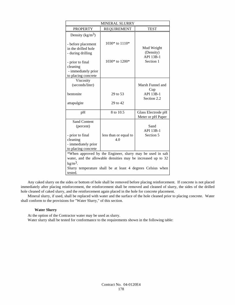
Contract No. 04-0120E4178
MINERAL SLURRYPROPERTY REQUIREMENT TEST
Density (kg/m3)
- before placementin the drilled hole- during drilling
- prior to finalcleaning - immediately priorto placing concrete
1030* to 1110*
1030* to 1200*
Mud Weight(Density)
API 13B-1Section 1
Viscosity(seconds/liter)
bentonite
attapulgite
29 to 53
29 to 42
Marsh Funnel andCup
API 13B-1Section 2.2
pH 8 to 10.5 Glass Electrode pHMeter or pH Paper
Sand Content(percent)
- prior to finalcleaning- immediately priorto placing concrete
less than or equal to4.0
SandAPI 13B-1Section 5
*When approved by the Engineer, slurry may be used in saltwater, and the allowable densities may be increased up to 32kg/m3.Slurry temperature shall be at least 4 degrees Celsius whentested.
Any caked slurry on the sides or bottom of hole shall be removed before placing reinforcement. If concrete is not placedimmediately after placing reinforcement, the reinforcement shall be removed and cleaned of slurry, the sides of the drilledhole cleaned of caked slurry, and the reinforcement again placed in the hole for concrete placement.
Mineral slurry, if used, shall be replaced with water and the surface of the hole cleaned prior to placing concrete. Watershall conform to the provisions for "Water Slurry," of this section.
Water SlurryAt the option of the Contractor water may be used as slurry.Water slurry shall be tested for conformance to the requirements shown in the following table:
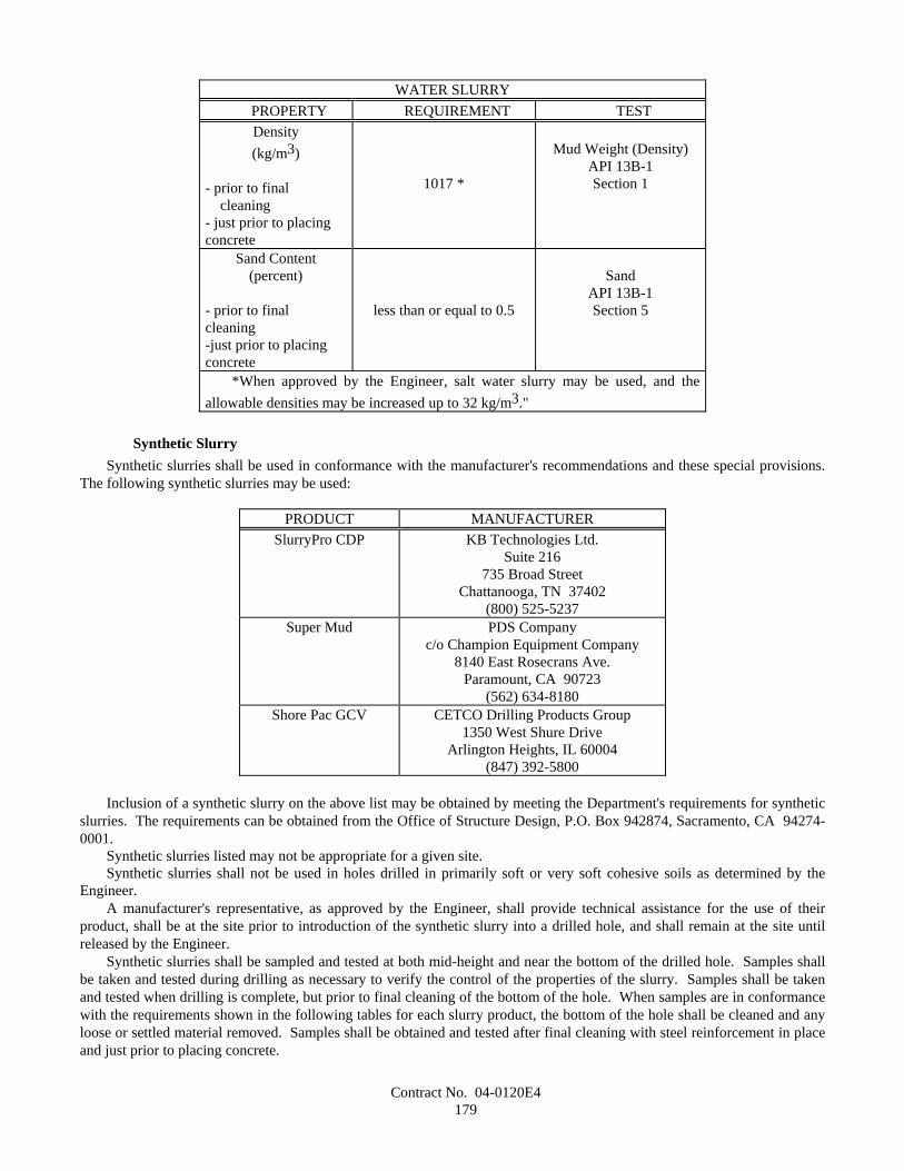
Contract No. 04-0120E4179
WATER SLURRYPROPERTY REQUIREMENT TESTDensity(kg/m3)
- prior to final cleaning- just prior to placingconcrete
1017 *
Mud Weight (Density)API 13B-1Section 1
Sand Content(percent)
- prior to finalcleaning-just prior to placingconcrete
less than or equal to 0.5
SandAPI 13B-1Section 5
*When approved by the Engineer, salt water slurry may be used, and theallowable densities may be increased up to 32 kg/m3."
Synthetic SlurrySynthetic slurries shall be used in conformance with the manufacturer's recommendations and these special provisions.
The following synthetic slurries may be used:
PRODUCT MANUFACTURERSlurryPro CDP KB Technologies Ltd.
Suite 216735 Broad Street
Chattanooga, TN 37402(800) 525-5237
Super Mud PDS Companyc/o Champion Equipment Company
8140 East Rosecrans Ave.Paramount, CA 90723
(562) 634-8180Shore Pac GCV CETCO Drilling Products Group
1350 West Shure DriveArlington Heights, IL 60004
(847) 392-5800
Inclusion of a synthetic slurry on the above list may be obtained by meeting the Department's requirements for syntheticslurries. The requirements can be obtained from the Office of Structure Design, P.O. Box 942874, Sacramento, CA 94274-0001.
Synthetic slurries listed may not be appropriate for a given site.Synthetic slurries shall not be used in holes drilled in primarily soft or very soft cohesive soils as determined by the
Engineer.A manufacturer's representative, as approved by the Engineer, shall provide technical assistance for the use of their
product, shall be at the site prior to introduction of the synthetic slurry into a drilled hole, and shall remain at the site untilreleased by the Engineer.
Synthetic slurries shall be sampled and tested at both mid-height and near the bottom of the drilled hole. Samples shallbe taken and tested during drilling as necessary to verify the control of the properties of the slurry. Samples shall be takenand tested when drilling is complete, but prior to final cleaning of the bottom of the hole. When samples are in conformancewith the requirements shown in the following tables for each slurry product, the bottom of the hole shall be cleaned and anyloose or settled material removed. Samples shall be obtained and tested after final cleaning with steel reinforcement in placeand just prior to placing concrete.
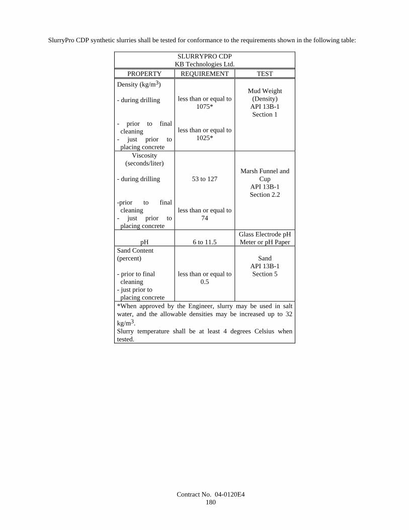
Contract No. 04-0120E4180
SlurryPro CDP synthetic slurries shall be tested for conformance to the requirements shown in the following table:
SLURRYPRO CDPKB Technologies Ltd.
PROPERTY REQUIREMENT TESTDensity (kg/m3)
- during drilling
- prior to finalcleaning
- just prior toplacing concrete
less than or equal to1075*
less than or equal to1025*
Mud Weight(Density)
API 13B-1Section 1
Viscosity(seconds/liter)
- during drilling
-prior to finalcleaning
- just prior toplacing concrete
53 to 127
less than or equal to74
Marsh Funnel andCup
API 13B-1Section 2.2
pH 6 to 11.5Glass Electrode pHMeter or pH Paper
Sand Content(percent)
- prior to finalcleaning
- just prior toplacing concrete
less than or equal to0.5
SandAPI 13B-1Section 5
*When approved by the Engineer, slurry may be used in saltwater, and the allowable densities may be increased up to 32kg/m3.Slurry temperature shall be at least 4 degrees Celsius whentested.
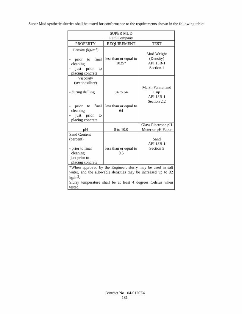
Contract No. 04-0120E4181
Super Mud synthetic slurries shall be tested for conformance to the requirements shown in the following table:
SUPER MUDPDS Company
PROPERTY REQUIREMENT TESTDensity (kg/m3)
- prior to finalcleaning
- just prior toplacing concrete
less than or equal to1025*
Mud Weight(Density)
API 13B-1Section 1
Viscosity(seconds/liter)
- during drilling
- prior to finalcleaning
- just prior toplacing concrete
34 to 64
less than or equal to64
Marsh Funnel andCup
API 13B-1Section 2.2
pH 8 to 10.0Glass Electrode pHMeter or pH Paper
Sand Content(percent)
- prior to finalcleaning
-just prior toplacing concrete
less than or equal to0.5
SandAPI 13B-1Section 5
*When approved by the Engineer, slurry may be used in saltwater, and the allowable densities may be increased up to 32kg/m3.Slurry temperature shall be at least 4 degrees Celsius whentested.
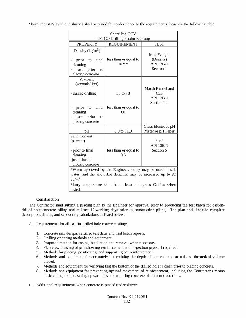
Contract No. 04-0120E4182
Shore Pac GCV synthetic slurries shall be tested for conformance to the requirements shown in the following table:
Shore Pac GCVCETCO Drilling Products Group
PROPERTY REQUIREMENT TESTDensity (kg/m3)
- prior to finalcleaning
- just prior toplacing concrete
less than or equal to1025*
Mud Weight(Density)
API 13B-1Section 1
Viscosity(seconds/liter)
- during drilling
- prior to finalcleaning
- just prior toplacing concrete
35 to 78
less than or equal to60
Marsh Funnel andCup
API 13B-1Section 2.2
pH 8.0 to 11.0Glass Electrode pHMeter or pH Paper
Sand Content(percent)
- prior to finalcleaning
-just prior toplacing concrete
less than or equal to0.5
SandAPI 13B-1Section 5
*When approved by the Engineer, slurry may be used in saltwater, and the allowable densities may be increased up to 32kg/m3.Slurry temperature shall be at least 4 degrees Celsius whentested.
ConstructionThe Contractor shall submit a placing plan to the Engineer for approval prior to producing the test batch for cast-in-
drilled-hole concrete piling and at least 10 working days prior to constructing piling. The plan shall include completedescription, details, and supporting calculations as listed below:
A. Requirements for all cast-in-drilled hole concrete piling:
1. Concrete mix design, certified test data, and trial batch reports.2. Drilling or coring methods and equipment.3. Proposed method for casing installation and removal when necessary.4. Plan view drawing of pile showing reinforcement and inspection pipes, if required.5. Methods for placing, positioning, and supporting bar reinforcement.6. Methods and equipment for accurately determining the depth of concrete and actual and theoretical volume
placed.7. Methods and equipment for verifying that the bottom of the drilled hole is clean prior to placing concrete.8. Methods and equipment for preventing upward movement of reinforcement, including the Contractor's means
of detecting and measuring upward movement during concrete placement operations.
B. Additional requirements when concrete is placed under slurry:
Contract No. 04-0120E4183
1. Concrete batching, delivery, and placing systems including time schedules and capacities therefor. Timeschedules shall include the time required for each concrete placing operation at each pile.
2. Concrete placing rate calculations. When requested by the Engineer, calculations shall be based on the initialpump pressures or static head on the concrete and losses throughout the placing system, including anticipatedhead of slurry and concrete to be displaced.
3. Suppliers test reports on the physical and chemical properties of the slurry and any proposed slurry chemicaladditives including Material Safety Data Sheet.
4. Slurry testing equipment and procedures.5. Removal and disposal of excavation, slurry, and contaminated concrete, including methods and rates of
removal.6. Slurry agitating, recirculating, and cleaning methods and equipment.
In addition to compressive strength requirements, the consistency of the concrete to be deposited under slurry shall beverified before use by producing a batch to be tested. The test batch shall be produced and delivered to the project underconditions and in time periods similar to those expected during the placement of concrete in the piles. Concrete for the testbatch shall be placed in an excavated hole or suitable container of adequate size to allow testing in conformance withCalifornia Test 533. Depositing of test batch concrete under slurry will not be required. For piles where the time requiredfor each concrete placing operation, as submitted in the placing plan, will be 2 hours or less, the test batch shall demonstratethat the proposed concrete mix design achieves both the specified nominal penetration and a penetration of at least 50 mmafter twice that time has elapsed. For piles where the time required for each concrete placing operation, as submitted in theplacing plan, will be more than 2 hours, the test batch shall demonstrate that the proposed concrete mix design achieves boththe specified nominal penetration and a penetration of at least 50 mm after that time plus 2 hours has elapsed. The timeperiod shall begin at the start of placement. The concrete shall not be vibrated or agitated during the test period. Uponcompletion of testing, the concrete shall be disposed of in conformance with the provisions in Section 7-1.13, "Disposal ofMaterial Outside the Highway Right of Way," of the Standard Specifications.
Concrete deposited under slurry shall not be vibrated until all concrete contaminated with soil, slurry, or other materialsis removed. Concrete deposited under slurry shall be vibrated in the upper 6 m of the pile.
The concrete deposited under slurry shall be carefully placed in a compact, monolithic mass and by a method that willprevent washing of the concrete. Placing concrete shall be a continuous operation lasting not more than the time required foreach concrete placing operation at each pile, as submitted in the placing plan, unless otherwise approved in writing by theEngineer. The concrete shall be placed with concrete pumps and delivery tube system of adequate number and size tocomplete the placing of concrete in the time specified. The delivery tube system shall consist of one of the following:
A. A tremie tube or tubes, each of which are at least 250 mm in diameter, fed by one or more concrete pumps.B. One or more concrete pump tubes, each fed by a single concrete pump.
The delivery tube system shall consist of watertight tubes with sufficient rigidity to keep the ends always in the mass ofconcrete placed. If only one delivery tube is utilized to place the concrete, the tube shall be placed near the center of thedrilled hole. Multiple tubes shall be uniformly spaced in the hole. Internal bracing for the steel reinforcing cage shallaccommodate the delivery tube system. Tremies shall not be used for piles without space for a 250-mm tube.
Spillage of concrete into the slurry during concrete placing operations will not be permitted. Delivery tubes shall becapped with a water tight cap, or plugged above the slurry level with a good quality, tight fitting, moving plug that will expelthe slurry from the tube as the tube is charged with concrete. The cap or plug shall be designed to be released as the tube ischarged. The pump discharge or tremie tube shall extend to the bottom of the hole before charging the tube with concrete.After charging the delivery tube system with concrete, the flow of concrete through a tube shall be induced by slightlyraising the discharge end. During concrete placement, the tip of the delivery tube shall be maintained to prevent reentry ofthe slurry into the tube. Until at least 3 m of concrete has been placed, the tip of the delivery tube shall be within 150 mm ofthe bottom of the drilled hole, and then the embedment of the tip shall be maintained at least 3 m below the top surface of theconcrete. Rapid raising or lowering of the delivery tube shall not be permitted. If the seal is lost or the delivery tubebecomes plugged and must be removed, the tube shall be withdrawn, the tube cleaned, the tip of the tube capped to prevententrance of the slurry, and the operation restarted by pushing the capped tube 3 m into the concrete and then reinitiating theflow of concrete.
When slurry is used, a fully operational standby concrete pump, adequate to complete the work in the time specified,shall be provided at the site during concrete placement. The slurry level shall be maintained within 300 mm of the top of thedrilled hole.
A log of concrete placement for each drilled hole shall be maintained by the Contractor when concrete is depositedunder slurry. The log shall show the pile location, tip elevation, dates of excavation and concrete placement, total quantity ofconcrete deposited, length and tip elevation of any casing, and details of any hole stabilization method and materials used.
Contract No. 04-0120E4184
The log shall include a 215 mm x 280 mm sized graph of the concrete placed versus depth of hole filled. The graph shall beplotted continuously throughout placing of concrete. The depth of drilled hole filled shall be plotted vertically with the piletip oriented at the bottom and the quantity of concrete shall be plotted horizontally. Readings shall be made at least at each1.5 m of pile depth, and the time of the reading shall be indicated. The graph shall be labeled with the pile location, tipelevation, cutoff elevation, and the dates of excavation and concrete placement. The log shall be delivered to the Engineerwithin one working day of completion of placing concrete in the pile.
After placing reinforcement and prior to placing concrete in the drilled hole, if drill cuttings settle out of the slurry, thebottom of the drilled hole shall be cleaned. The Contractor shall verify that the bottom of the drilled hole is clean.
Material resulting from using slurry shall be disposed of in conformance with the provisions in "Dredging," of thesespecial provisions.
Permanent steel casings shall be furnished and grouted in the hole where shown on the plans. Permanent casings shallnot be driven. Permanent casings shall be watertight and of sufficient strength to withstand the loads from installationprocedures, lateral concrete pressures, and earth pressures, and shall conform to the provisions of "Steel Pipe Piling" of thesespecial provisions.
If conditions render it impossible or inadvisable in the opinion of the Engineer to dewater the permanent steel casingprior to drilling or coring the rock socket below, then the bottom of the casing shall be sealed in conformance with theprovisions in Section 51-1.10, "Concrete Deposited Under Water," of the Standard Specifications. The sealed casing shallthen be dewatered and cleaned out as specified herein.
Acceptance Testing and MitigationVertical inspection pipes for acceptance testing shall be provided in all cast-in-drilled-hole concrete piles, except when
the holes are dry or dewatered.Inspection pipes shall be Schedule 40 polyvinyl chloride pipe with a nominal inside diameter of 50 mm and NPS 2,
Schedule 40, black steel pipe. Each inspection pipe shall be capped top and bottom and shall have watertight couplers toprovide a clean, dry and unobstructed 50-mm diameter clear opening from 1.0 m above the pile cutoff down to the bottom ofthe reinforcing cage.
If the Contractor drills the hole below the specified tip elevation, the reinforcement and the inspection pipes shall beextended to 75 mm clear of the bottom of the drilled hole.
Inspection pipes shall be placed as shown on the plans 75 mm clear of the vertical reinforcement. The inspection pipesshall be placed to provide the maximum diameter circle that passes through the centers of the inspection pipes whilemaintaining the clear spacing required herein. The pipes shall be installed in straight alignment, parallel to the mainreinforcement, and securely fastened in place to prevent misalignment during installation of the reinforcement and placing ofconcrete in the hole.
At the Pier T1 footing where inspection pipes are required by these special provisions, the Contractor shall constructworking platforms at least 1.5 m above the higher high tide line and extend inspection pipes above the working platform.Acceptance testing shall be performed from the platform. The platform shall be sufficiently rigid to provide a safe, stableworking area for the Engineer and testing equipment. The platform shall be designed for a minimum uniform load of4.8 kPa. The Contractor shall submit working drawings for the platforms to the Engineer for review in accordance with theprovisions in "Working Drawings," of these special provisions. The Engineer will submit to BCDC for final plan review; theEngineer and BCDC will review and the Engineer will provide comments to the Contractor within 70 calendar days. TheContractor will have 10 working days to revise and resubmit.
The Contractor shall log the location of the inspection pipe couplers with respect to the plane of pile cutoff. These logsshall be delivered to the Engineer upon completion of the placement of concrete in the drilled hole.
After placing concrete and before requesting acceptance tests, each inspection pipe shall be tested by the Contractor inthe presence of the Engineer by passing a 48.3-mm diameter rigid cylinder 610 mm long through the complete length ofpipe. If the 48.3-mm diameter rigid cylinder fails to pass any of the inspection pipes, the Contractor shall attempt to pass a32.0-mm diameter rigid cylinder 1.375 m long through the complete length of those pipes in the presence of the Engineer. Ifan inspection pipe fails to pass the 32.0-mm diameter cylinder, the Contractor shall immediately fill all inspection pipes inthe pile with water.
The Contractor shall replace each inspection pipe that does not pass the 32.0-mm diameter cylinder with a 50.8-mmdiameter hole cored through the concrete for the entire length of the pile. Cored holes shall be located as close as possible tothe inspection pipes they are replacing, no more than 150 mm inside the reinforcement. Coring shall not damage the pilereinforcement. Cored holes shall be made with a double wall core barrel system utilizing a split tube type inner barrel.Coring with a solid type inner barrel will not be allowed. Coring methods and equipment shall provide intact cores for theentire length of the pile concrete. The coring operation shall be logged by an Engineering Geologist or Civil Engineerlicensed in the State of California and experienced in core logging. Coring logs shall include complete descriptions ofinclusions and voids encountered during coring, and shall be delivered to the Engineer upon completion. Concrete cores
Contract No. 04-0120E4185
shall be preserved, identified with the exact location the core was recovered from within the pile, and made available forinspection by the Engineer.
Acceptance tests of the concrete will be made by the Engineer, without cost to the Contractor. Acceptance tests willevaluate the homogeneity of the placed concrete. Tests will include gamma-gamma logging. Tests may also includecrosshole sonic logging and other means of inspection selected by the Engineer. The Contractor shall not conduct operationswithin 8.0 m of the gamma-gamma logging operations. The Contractor shall separate reinforcing steel as necessary to allowthe Engineer access to the inspection pipes to perform gamma-gamma logging or other acceptance testing. After requestingacceptance tests and providing access to the piling, the Contractor shall allow 3 weeks for the Engineer to conduct these testsand make determination of acceptance if the 48.3-mm diameter cylinder passed all inspection pipes, and 4 weeks if only the32.0-mm diameter cylinder passed all inspection pipes. Should the Engineer fail to complete these tests within the timeallowance, and if in the opinion of the Engineer, the Contractor's controlling operation is delayed or interfered with by reasonof the delay in inspection, the delay will be considered a right of way delay as specified in Section 8-1.09, "Right of WayDelays," of the Standard Specifications.
All inspection pipes and cored holes in a pile shall be dewatered and filled with grout after notification by the Engineerthat the pile is acceptable. Placement and removal of water in the inspection pipes shall be at the Contractors expense. Groutshall conform to the provisions in Section 50-1.09, "Bonding and Grouting," of the Standard Specifications. The inspectionpipes and holes shall be filled using grout tubes that extend to the bottom of the pipes or holes or into the grout alreadyplaced.
If acceptance testing performed by the Engineer determines that a pile does not meet the requirements of these specialprovisions, then that pile will be rejected and all depositing of concrete under slurry or concrete placed using temporarycasing for the purpose of controlling groundwater shall be suspended until written changes to the methods of pileconstruction are approved in writing by the Engineer.
The Contractor shall submit to the Engineer for approval a mitigation plan for repair, supplementation, or replacementfor each rejected cast-in-drilled-hole concrete pile. This plan shall conform to the provisions in "Working Drawings," ofthese special provisions. Prior to submitting this mitigation plan, the Engineer will hold a repair feasibility meeting with theContractor to discuss the feasibility of repairing rejected piling. The Engineer will consider the size of the defect, thelocation of the defect, and the design information and corrosion protection considerations for the pile. This information willbe made available to the Contractor, if appropriate, for the development of the mitigation plan. If the Engineer determinesthat it is not feasible to repair the rejected pile, the Contractor shall not include repair as a means of mitigation and shallproceed with the submittal of a mitigation plan for replacement or supplementation of the rejected pile.
If the Engineer determines that a rejected pile does not require mitigation due to structural, geotechnical, or corrosionconcerns, the Contractor may elect to 1) repair the pile per the approved mitigation plan, or 2) not repair anomalies foundduring acceptance testing of that pile. For such unrepaired piles, the Contractor shall pay to the State, $400 per cubic meterfor the portion of the pile affected by the anomalies. The volume, in cubic meters, of the portion of the pile affected by theanomalies, shall be calculated as the area of the cross-section of the pile affected by each anomaly, in square meters, asdetermined by the Engineer, multiplied by the distance, in meters, from the top of each anomaly to the specified tip of thepile. If the volume calculated for one anomaly overlaps the volume calculated for additional anomalies within the pile, thecalculated volume for the overlap shall only be counted once. In no case shall the amount of the payment to the State for anysuch pile be less than $400. The Department may deduct the amount from any moneys due, or that may become due theContractor under the contract.
Pile mitigation plans shall include the following:
A. The designation and location of the pile addressed by the mitigation plan.B. A review of the structural, geotechnical, and corrosion design requirements of the rejected pile.C. A step by step description of the mitigation work to be performed, including drawings if necessary.D. An assessment of how the proposed mitigation work will address the structural, geotechnical, and corrosion design
requirements of the rejected pile.E. Methods for preservation or restoration of existing earthen materials.F. A list of affected facilities, if any, with methods and equipment for protection of these facilities during mitigation.G. The State assigned contract number, bridge number, full name of the structure as shown on the contract plans,
District-County-Route-Kilometer Post , and the Contractor's (and Subcontractor's if applicable) name on each sheet.H. A list of materials, with quantity estimates, and personnel, with qualifications, to be used to perform the mitigation
work.I. The seal and signature of an engineer who is licensed as a Civil Engineer by the State of California.
For rejected piles to be repaired, the Contractor shall submit a pile mitigation plan that contains the following additionalinformation:
Contract No. 04-0120E4186
A. An assessment of the nature and size of the anomalies in the rejected pile.B. Provisions for access for additional pile testing if required by the Engineer.
For rejected piles to be replaced or supplemented, the Contractor shall submit a pile mitigation plan that contains thefollowing additional information:
A. The proposed location and size of additional piling.B. Structural details and calculations for any modification to the structure to accommodate the replacement or
supplemental piling.
All provisions for cast-in-drilled-hole concrete piling shall apply to replacement piling.The Contractor shall allow the Engineer 3 weeks to review the mitigation plan after a complete submittal has been
received.When repairs are performed, the Contractor shall submit a mitigation report to the Engineer within 10 days of
completion of the repair. This report shall state exactly what repair work was performed and quantify the success of therepairs relative to the submitted mitigation plan. The mitigation report shall be stamped and signed by an engineer who islicensed as a Civil Engineer by the State of California. The mitigation report shall show the State assigned contract number,bridge number, full name of the structure as shown on the contract plans, District-County-Route-Kilometer Post, and theContractor (and Subcontractor if applicable) name on each sheet. The Engineer will be the sole judge as to whether amitigation proposal is acceptable, the mitigation efforts are successful, and to whether additional repairs, removal andreplacement, or construction of a supplemental foundation is required.
OPEN ENDED CAST-IN-STEEL-SHELL CONCRETE PILING
GeneralCast-in-steel-shell concrete piling shall consist of open ended steel shells driven to the specified penetration and filled
with reinforced cast-in-place concrete and shall conform to the provisions in Section 49-4, "Cast-in-Place Concrete Piles," ofthe Standard Specifications and these special provisions.
In addition to driving, drilling or jetting within open ended steel shells to remove the soil plug may be necessary toobtain the specified penetration. The diameter of drilled holes shall be less than the clear inside diameter of the piling,including the interior weld beads. Jetting methods and procedures shall demonstrate that soil plug removal can be done at apredicted rate and in a controlled manner. Equipment or methods used for drilling or jetting shall not cause quick soilconditions, scouring, or caving of the hole and shall not damage the interior weld beads. If soil plug removal operationsextend below the limit of the seal course concrete, as shown on the plans, the Contractor shall fill the void created by drillingor jetting with additional seal course concrete. Drilling or jetting shall not disturb the soil plug within 7 meters of the pile toeat any time during pile installation.
The steel shells shall be installed open ended and shall have interior and exterior weld beads, as shown on the plans.
Steel ShellsAttention is directed to "Steel Pipe Piling," of these special provisions.
ReinforcementReinforcement shall conform to the provisions in "Reinforcement," of these special provisions. Headed bar
reinforcement shall conform to the provisions in "Headed Bar Reinforcement," of these special provisions.
ConstructionThe Contractor shall submit to the Engineer for approval, a cleanout and inspection plan for open ended cast-in-steel-
shell concrete piling. Care shall be taken during cleaning out of open ended steel shells to prevent disturbing the foundationmaterial surrounding the pile and damaging the interior weld beads. The pile soil plug, as shown on the plans, shall not becleaned out. Equipment or methods used for cleaning out steel shells shall not cause quick soil conditions or cause scouringor caving around or below the piles. Open ended steel shells shall be free of any soil, rock, or other material deleterious tothe bond between concrete and steel prior to placing reinforcement and concrete. Interior surfaces of open ended steel shellsand interior weld beads shall be 100% clean.
Verification of pile cleanout shall be demonstrated by a video camera capable of inspecting any location within the steelshell. At the option of the Engineer, verification of pile cleanout shall be by either real-time viewing of the inspection by the

Contract No. 04-0120E4187
Engineer or by the Engineer viewing a recorded inspection of mutually agreed sections of the pile. Recordings shall indicatethe azimuth and depth of the camera.
Drilling fluid, except for water, shall not be used inside the steel shell during the cleanout process.The Contractor shall allow the Engineer 70 working days for review of the cleanout and inspection plan.After the steel shells have been cleaned out, the pile shall be constructed expeditiously in order to prevent deterioration
of the surrounding foundation material from the presence of water. Deteriorated foundation materials, including materialsthat have softened, swollen, or degraded, shall be removed from the bottom of the steel shells and shall be disposed of.
Material resulting from cleaning out the steel shells shall be disposed of in conformance with the provisions in"Dredging," of these special provisions, unless otherwise specified or permitted by the Engineer.
Reinforcement shall be placed and secured symmetrically about the axis of the pile and shall be securely blocked to clearthe sides of the steel shell and the interior weld beads, and blocked or suspended to clear the top of the soil plug.
Concrete fill for cast-in-place concrete piles shall be placed continuously. Construction joints will not be permitted.Concrete fill for cast-in-place piles shall be placed by use of a tremie tube or tubes, each of which are at least 250 mm in
diameter. A hopper shall be attached to the tremie tube(s). Concrete pumps may be used to deliver concrete to a hopper thatfeeds the tremie tube(s). Pumping concrete directly down the tremie tube will not be permitted. Internal bracing for the steelreinforcing cage shall accommodate the delivery tube system.
Delivery tubes shall be capped with a watertight cap, or plugged with a good quality, tight-fitting, moving plug. The capor plug shall be designed to release as the tube is charged with concrete. The tremie tube shall extend to the top of the soilplug before charging the tube with concrete.
STEEL PIPE PILING
GeneralSteel pipe piling shall consist of steel shells for open ended cast-in-steel-shell concrete piling, and permanent steel
casing for cast-in-drilled-hole concrete piling. Steel pipe piling shall conform to the provisions in Section 49-5, "Steel Piles,"of the Standard Specifications and these special provisions.
Attention is directed to "Welding" of these special provisions regarding welding of steel pipe. Unless otherwisespecified, welding of any work performed in conformance with the provisions in Section 49, "Piling," of the StandardSpecifications, shall be in conformance with the requirements in AWS D1.1.
Wherever reference is made to the following American Petroleum Institute (API) specifications in the StandardSpecifications, on the project plans, or in these special provisions, the year of adoption for these specifications shall be asfollows:
API Codes Year of AdoptionAPI SPEC 2B 1996
All requirements of the codes listed above shall apply unless specified otherwise in the Standard Specifications, on theplans or in these special provisions.
Handling devices may be attached to steel pipe piling. Welds attaching these devices shall be aligned parallel to the axisof the pile and shall conform to the requirements of field welding specified herein. All handling devices shall be removedfrom the permanent piling when no longer needed. All remaining welds shall be ground flush. Prior to making attachments,the Contractor shall submit a plan to the Engineer that includes the locations, handling and fitting device details, connectiondetails, welding and removal procedures. Attachments shall not be made to the steel pipe piling until the plan is approved inwriting by the Engineer. The Engineer shall have 7 working days to review the plan.
For steel pipe piling, including any bar reinforcement in the piling, the time to be allowed for the Engineer to review the"Welding Report," specified in "Welding" of these special provisions, and respond in writing after all the required items havebeen received, shall be as follows:
Type of Welding Review TimeOffshore field welding 48 hoursBar reinforcement in
piling72 hours
All other pile welding 6 working days
Contract No. 04-0120E4188
Offshore field welding is defined as steel pipe pile splice welds made after stabbing the pile. No field welded steel pipepiling shall be installed, and no reinforcement in the piling shall be encased in concrete until the Engineer has approved theabove requirements in writing.
At the Contractor's option, a steel pipe pile may be re-tapped to prevent pile set-up; however, the field welded spliceshall remain at least one meter above the work platform until that splice is approved in writing by the Engineer.
The Contractor shall provide durable enclosures at field splice locations to allow welding during inclement weatherconditions in accordance with the requirements in "Welding," of these special provisions.
Fabricated Steel PipeFabricated steel pipe is defined as pipe produced at a permanent facility where a variety of steel fabrication including
roll forming and welding steel plate into pipe is performed, where this pipe is at least 19 mm in wall thickness, where thispipe is produced in conformance with API SPEC 2B, and where this fabrication can be done on a daily basis. Fabricatedsteel pipe is a specifically engineered product. (i.e. Fabricated steel pipe is engineered for a specific project.)
Fabricated steel pipe used for steel pipe piling shall conform to API SPEC 2B and the following requirements:
A. An API site license and API monogram are not required.B. Weld filler metal shall conform to the requirements in AWS D1.5 for the welding of ASTM Designation: A 709M,
Grade 345 steel, except that the qualification, pretest, and verification test requirements need not be conducted ifcertified test reports are provided for the consumables to be used.
C. Steel pipe piles shall be fabricated from plate conforming to the requirements in ASTM A 709M, Grade 345 withSupplementary Requirement S83 "Non-Fracture-Critical, T, Material; Toughness Test and Marking" for Zone II.
D. The sulfur content of steel pipe piles shall not exceed 0.05 percent, except where through-thickness is designated onthe plans. Where through-thickness is designated on the plans, steel shall conform to the low sulfur and 20%reduction of area requirements in AWS D1.5, Section 12.4.4.1.
E. The acceptance criteria for visual inspection of pile welds shall be AWS D1.1 criteria for statically loadedstructures, except within the "Plastic Hinge Zone" designated on the plans, where the criteria for cyclically loadedstructures subject to tensile stress shall apply.
F. The thickness transition between the pile sections with different wall thickness shall be no steeper than 1:3.
Pile Weld BeadsThe profile of the pile weld beads shall conform to the details shown on the plans and AWS D1.1, Section 6.9 for
cyclically loaded welds (weld beads are within the Plastic Hinge Zone of the pile), as modified herein.
A. The specified weld size shall be as shown on the plans, except a 1.5 mm undertolerance on bead height will bepermitted providing the cumulative length does not exceed 10% of the weld length in any meter.
B. Undercut shall not exceed 0.25 mm.C. The minimum reentrant angle between the base metal and weld bead is 90 degrees.D. Overlap will not be permitted for specified weld bead heights of 10 mm or less. For specified weld bead heights
that exceed 10 mm, overlap shall not exceed 3 mm in layers above the first, except overlap that restricts access forinspecting the weld toe will not be permitted regardless of size. Overlap will not be permitted for the first weldlayer.
Pile weld beads shall be qualified by making a sample of the weld bead that is at least 1.5 m long. The weld shallconform to the specified geometry and shall be accepted visually and by MT. The macroetch specimens shall be taken fromthe areas with the poorest profile as determined by the Engineer. The macroetch specimens shall not have any cracks orfissures; shall have full fusion to the parent metal and between passes; and shall conform to the specified profilerequirements.
Field WeldingField welding of steel pipe piling is defined as welding performed after the certificate of compliance has been furnished
by the fabricator.Field welding of permanent steel casings will not be permitted.Field welding of steel shells shall conform to the following requirements:
A. Prior to positioning any 2 sections of steel pipe to be spliced by field welding, the Contractor shall minimize theoffsets of the pipe ends to be joined .
Contract No. 04-0120E4189
B. Welds made in the flat position or vertical position (where the longitudinal pipe axis is horizontal) shall be single-vee or double-vee groove welds. Welds made in the horizontal position (where the longitudinal pipe axis isvertical) shall be single-bevel welds. Joint fit-ups shall conform to the requirements in AWS D1.1 and these specialprovisions.
C. The minimum thickness of the backing ring shall be 6 mm, and the ring shall be continuous. Splices in the backingring shall be made by complete penetration welds. Radiographic or ultrasonic testing in conformance with therequirements in AWS D1.1, Section 6, shall be used on each splice weld to assure soundness of backing ring splicesprior to final insertion into a pipe end. Attachment of backing rings to pipe ends shall be done using a continuousfillet weld on the inside of the pile. After fitting to the second pipe, tack welding shall be done in the root area ofthe weld splice or to spacers. Minimum size and length of tack welds shall be as defined by AWS D1.1,Section 2.4.6. The gap between the backing ring and the steel pipe piling wall shall be no greater than 2 mm, exceptas follows:
1. Gaps greater than 2 mm, but not exceeding 6 mm may be seal welded using E7018 SMAW.2. Gaps exceeding 6 mm shall be repaired by welding using E7018 SMAW, the weld groove shall be ground to
provide the intended groove shape, and the area shall be inspected using magnetic particle testing prior tostarting the groove weld.
Locations where fit-up gaps exceed 2 mm shall be marked so that they can be referenced during non-destructivetesting (NDT). Backing rings shall have a minimum width of 3 times the thickness of the steel pipe piling to bewelded so that the ring will not interfere with the interpretation of the NDT.
D. The weld groove root opening tolerance may be increased to a maximum of 5 mm over the specified tolerance.E. Weld filler metal shall conform to the requirements in AWS D1.5, Table 4.1 or 4.2, for the welding of ASTM
Designation: A 709M, Grade 345 steel, and shall be designated H8 or less by the manufacturer.F. Prequalified welding procedures will not be permitted for pile splices. All field welding procedures shall be
qualified by testing in conformance with the requirements in AWS D1.1 and these special provisions. Using thequalified weld procedure specification (WPS), a minimum of two additional weld mock-ups will be required toqualify offshore field welding, and both shall use full sized pipe pile sections to simulate the field girth weld. Allmock-up welding shall be performed outside in the enclosure that will be used during offshore installation. Bothwelds shall be made in the positions to be used in production. Each weld need not exceed 1 m in length, and allpasses shall be stopped and restarted at the same location in the middle of the weld. The first weld shall be preparedand welded using the proposed production weld joint detail and welding parameters. The second weld shallsimulate the most onerous combination of weld root opening, root face and backing ring gap anticipated for field fit-up, as approved by the Engineer. The out-of-tolerance fit-up shall be repaired and accepted per these specificationsbefore completing the weld. The completed welds shall be examined by the ultrasonic testing (UT) procedureproposed for production joints, and any significant indications shall be marked for sectioning to confirm the UTresults prior to mechanical testing the weldment. Qualification tests shall include all tests required by AWS D1.1,macroetch sections of the center stop-start location and all areas marked during UT, and Charpy V-Notch tests at-20°C of the weld metal. The Charpy tests shall meet 27 Joules minimum average and 20 Joules minimumindividual.
G. The welding filler materials (wire/electrode and flux, if used) shall be considered an essential variable for weldingprocedure qualification. Any change in the filler material brand name or type shall require requalification of thewelding procedure.
H. GMAW shall not be used for field welding.I. For field welding, including attaching backing rings and making repairs, the preheat and interpass temperature shall
be in conformance with AWS D1.1, Table 3.2, Category C; and the minimum preheat and interpass temperatureshall be 65°C, regardless of the pipe wall thickness or steel grade. In the event welding is interrupted, preheating to65°C must occur before welding is resumed. For girth welds with required preheat temperatures greater than 65°C,preheat temperatures shall be achieved and maintained using electric resistance heating bands for the entire lengthof the weld. The heaters shall be controlled by attached thermocouples at spacings not exceeding 2 m. For thesewelds, the minimum preheat temperature shall be maintained continuously from beginning to completion of theentire weld, even if welding is interrupted.
J. Welds shall not be water quenched. Welds shall be allowed to cool unassisted.K. Stray current corrosion of the structure shall be avoided during installation at the site. Welding machines shall be
placed on the structure being welded. Where this is not practical, the insulated welded power source output"ground" lead shall be connected directly to the work at a location close to the weld being made and shall not be
Contract No. 04-0120E4190
permitted to touch the water. The minimum total cross sectional area of the return ground cable(s) shall be 645circular mm per 1000 amperes per 30.5 m of cable. Grounding sufficiency shall be periodically monitored bysimultaneously measuring the potential of the structure being welded and that holding the welding machines using astandard calomel electrode (SCE), Ag-AgCl or other reference electrode approved by the Engineer. A change inpotential reading of 10% or more shall indicate insufficient grounding.
NONDESTRUCTIVE TESTING FOR STEEL PIPE PILINGSteel pipe piling shall receive nondestructive testing (NDT) in conformance with these special provisions.
Nondestructive Testing of Welds made at a Fabrication FacilityTwenty-five percent of each longitudinal and 100 percent of each circumferential weld made shall receive NDT by
either radiographic, radioscopic, real time imaging systems or ultrasonic methods that are in conformance with therequirements in AWS D1.1. The acceptance and repair criteria shall conform to the requirements in AWS D1.1, Section 6,for statically loaded structures under tensile stress, except within the "Plastic Hinge Zone" designated on the plans, where thecriteria for cyclically loaded nontubular connections subject to tensile stress shall apply. Any required repair, from defectslocated by NDT, shall be completed and then re-examined by the same NDT method with an additional 10 percent of theweld repair length, not to be less than 50 mm, at each end of the weld repair. In addition, if repairs are required in a portionof a weld not 100 percent examined by NDT, an additional 10 percent of the total length of the weld shall be examined bythe same NDT method on each side of the previously inspected length for a total of 20 percent. If the additional NDT andoriginal NDT required discover a cumulative length in weld repairs equal to or greater than 10 percent of the total weldlength, than 100 percent of the weld length shall be examined by NDT.
Twenty-five percent of each pile interior and exterior weld bead shall receive magnetic particle examination inconformance with the requirements in AWS D1.1. The acceptance and repair criteria shall conform to the requirements inAWS D1.1, Section 6, for statically loaded structures under tensile stress, except within the "Plastic Hinge Zone" designatedon the plans, where the criteria for cyclically loaded nontubular connections subject to tensile stress shall apply. Anyrequired repairs, from defects located by MT, shall be completed and then re-examined by MT with an additional 10 percentof the weld repair. In addition, if repairs are required in a portion of a weld not 100 percent examined by MT, an additional10 percent of the total length of the weld shall be examined by MT on each side of the previously inspected length for a totalof 20 percent. After the additional NDT is performed, and if more repairs are required, then 100 percent of the weld lengthshall receive MT.
Nondestructive Testing of Field WeldsPrior to performing ultrasonic NDT on field welds, the Contractor's welding inspection personnel shall have passed
Caltrans' Ultrasonic Test. Field welding is defined as welding performed after the Certificate of Compliance has beenfurnished to the Engineer by the fabricator or manufacture for said materials. Information regarding the Caltrans UltrasonicTest (titled "Notification of California Department of Transportation Qualification Requirement for Ultrasonic TestingPersonnel) is included in the "Information Handout," available to the Contractor as provided for in Section 2-1.03,"Examination of Plans, Specifications, Contract and Site of Work," of the Standard Specifications. This test includes bothwritten and practical examinations.
Splices made by field welding steel pipe piling shall receive NDT as follows:
UT shall be used for each field weld, including splices that are made onto a portion of the steel pipe piling that hasbeen installed and any repair made to a splice weld. UT shall be performed over the full length of weld. Inaddition, Magnetic Particle testing (MT) shall be used for 100% of the root pass of all field welds unless otherwisedirected by the Engineer. The acceptance criteria shall conform to the requirements in AWS D1.1, Section 6, forstatically loaded nontubular connections subject to tensile stress. UT shall be performed in accordance with awritten procedure that shall be reviewed by the Engineer before use. The UT procedure shall address theunambiguous interpretation of indications from the weld root and backing and shall describe the treatment of rootfit-up repairs. The procedure shall define all measurements and/or marking that may be required prior to the start ofwelding. This procedure shall be demonstrated during weld mock-up qualification to verify its effectiveness indifferentiating root and repair conditions.
MEASUREMENT AND PAYMENT (PILING)The first paragraph of Section 49-6.01 "Measurement," of the Standard Specifications shall not apply.The length of furnish pile to be paid for shall be the total length of the pile, as shown on the plans, measured along the
centerline, from the specified pile tip of the pile to the plane of the pile cut-off. If the Contractor elects to furnish piling
Contract No. 04-0120E4191
longer than the piling shown on the plans, no adjustment will be made to the length of piling to be paid and payment will bebased on the length of pile shown on the plans.
The contract price paid per meter for cast-in-drilled-hole concrete piling shall include full compensation for furnishingall labor, materials, tools, equipment, and incidentals, and for doing all work involved in drilling holes, disposing of thematerial resulting from drilling holes, removing water when necessary, furnishing and placing concrete, and constructingreinforced concrete extensions, complete in place, to the required penetration as shown on the plans, as specified in theStandard Specifications and these special provisions, and as directed by the Engineer.
Payment for cast-in-place concrete piling shall conform to the provisions in Section 49-6.02, "Payment," of the StandardSpecifications and these special provisions except that reinforcement in the piling will be paid for by the kilogram as barreinforcing steel (bridge).
The sixth paragraph of Section 49-6.02 "Payment," of the Standard Specifications shall not apply.If steel shells are fabricated more than 480 airline kilometers from both Sacramento and Los Angeles, additional shop
inspection expenses will be sustained by the State. Whereas it is and will be impractical and extremely difficult to ascertainand determine the actual increase in such expenses, it is agreed that payment to the Contractor for furnishing steel shells willbe reduced $17 per meter of length of steel shell.
Full compensation for slurry, depositing concrete under slurry, test batches, inspection pipes, filling inspection holes andpipes with grout, drilling oversized cast-in-drilled-hole concrete piling, filling cave-ins and oversized piles with concrete,providing and verifying hole roughness, and redrilling through concrete, shall be considered as included in the contractprices paid per meter for cast-in-drilled-hole concrete piling of the types and sizes listed in the Engineer's Estimate, and noadditional compensation will be allowed therefor.
The contract price paid per meter for cast-in-drilled-hole concrete piling (rock socket) of the sizes listed in the Engineer'sEstimate shall include full compensation for furnishing all labor, materials, tools, equipment, and incidentals, and for doingall the work involved in drilling or coring holes, disposing of the material resulting from drilling or coring holes, andfurnishing and placing concrete, complete in place, to the required penetration, as shown on the plans, as specified in theStandard Specifications and these special provisions, and as directed by the Engineer.
Full compensation for designing, furnishing, constructing, and when no longer necessary, removing inspection platformsfor pile acceptance testing, and providing transportation and access for the Engineer for pile acceptance testing, includingextending inspection pipes up to the platform shall be considered as included in the contract prices paid per meter for cast-in-drilled-hole concrete piling of the sizes listed in the Engineer's Estimate and no additional compensation will be allowedtherefor.
The contract price paid per meter for permanent steel casing of the sizes listed in the Engineer's Estimate shall includefull compensation for furnishing all labor, materials, tools, equipment, and incidentals, and for doing all the work involved infurnishing and installing permanent steel casing, complete in place, including weld beads, as shown on the plans, as specifiedin the Standard Specifications and these special provisions, and as directed by the Engineer.
Full compensation for oversize holes and isolation material shall be considered as included in the contract price paid permeter for cast-in-drilled-hole concrete piling and no additional compensation will be allowed therefor.
Full compensation for cleaning out piles and providing video camera inspection for the steel shells shall be considered asincluded in the contract price paid per meter for cast-in-drilled-hole concrete piling and no additional compensation will beallowed therefor.
10-1.25 MARINE PILE DRIVING ENERGY ATTENUATORThis work shall consist of designing, furnishing, installing, operating, monitoring, maintaining, and removing an air
bubble curtain system to attenuate underwater energy generated by driving 2.5 meter cast-in-steel shell concrete piling. Forpurposes of this specification, pile installation refers to all the activities involved with driving a single pile; pile driving refersto the time when the hammer is physically driving the pile.
Attention is directed to "Relations with United States Coast Guard," of these special provisions regarding navigationrequirements.
The approved attenuator system shall be operating prior to beginning pile driving at any given pile location. If theattenuator fails, as determined by the Engineer, pile driving shall immediately stop. Piling driving at any given location shallnot resume until the attenuator system at that location is again operating in conformance with the requirements of thissection, as determined by the Engineer.
Failure of the attenuator system shall include, but not be limited to, the following methods of failure as determined bythe Engineer:
A. The pressure or flow rate in any meter falls below 90% of its operating value during the pile driving operation;B. During inspection of the perforated pipe the Engineer determines that erosion of the holes or debris has clogged the
holes that will degrade the performance of the system.
Contract No. 04-0120E4192
The Contractor shall make provisions for the Engineer to inspect the bubble curtain system for proper operation beforeeach deployment and as necessary during deployment. Proper operation during deployment will be determined byobservation of the gauges in the monitoring station and by other methods developed by the Engineer.
At the Contractor's option, cofferdams that conform to the following requirements may be used as a marine pile drivingenergy attenuator:
A. Cofferdams shall be continuous (no openings in the sides).B. Cofferdams shall be made of concrete or steel members.C. Cofferdams shall extend from Mean Higher High Water to at least 0.5 meters below the original mudline.D. Cofferdams shall be dewatered prior to pile driving.
The Contractor shall provide adequate means to prevent light from pile driving operations from shining directly into thewater. At least 15 minutes prior to and during pile driving operations, the Contractor shall not shine light directly into thewater in areas adjacent to piles being driven.
GENERALAn air bubble curtain system is generally composed of an air compressor(s), supply lines to deliver the air, distribution
manifolds or headers, perforated aeration pipes, and a frame. The frame facilitates transport and placement of the system,keeps the aeration pipes stable, and provides ballast to counteract the buoyancy of the aeration pipes in operation.
Air bubble curtain system shall conform to the following:
A. Air bubble system shall consist of multiple and concentric layers of perforated aeration pipes stacked vertically inaccordance with the following:
Water Depth (m) No. of Layers0 to less than 5 2
5 to less than 10 410 to less than 15 715 to less than 20 1020 to less than 25 13
B. Pipes in any layer shall be arranged in a geometric pattern, which shall allow for the pile driving operation to becompletely enclosed by bubbles for the full depth of the water column and for a radial dimension of no more than0.5 meters as measured from the outside surface of the pile.
C. The lowest layer of perforated aeration pipes shall be designed to ensure contact with the mudline without sinkinginto the bay mud.
D. The system shall provide a bubble flux of 2.0 cubic meters per minute per linear meter of pipe in each layer. Airholes shall be 1.6 mm in diameter and shall be spaced approximately 20 mm apart. Air holes shall be placed in fouradjacent rows along the pipe to provide uniform bubble flux.
E. Meters shall be provided in accordance with the following:
1. Pressure meters shall be installed at all inlets to aeration pipelines and at points of lowest pressure in eachbranch of the aeration pipeline.
2. The Flow meters shall be installed in the main line at each compressor and at each branch of the aerationpipelines at each inlet. In applications where the feedline from the compressor is continuous from thecompressor to the aeration pipe inlet, the flow meter at the compressor can be eliminated.
3. Flow meters shall be installed according to the manufacturer’s recommendation based on either laminar flow ornon-laminar flow, which ever applies.
Gauges shall be installed above the water line and shall be easily accessible to the Engineer. The Contractor shall keep acontinuous electronic log of all meters and gauges when the system is operating. Readings shall be logged every 30 minutesand at other times, as determined by the Engineer, when variation in the readings exceed 10%. The Contractor shall maintaina graphical plot showing the variation of the meter readings with time.
Air pressure and air flow meters and gauges shall be calibrated by a private laboratory approved by the Engineer prior touse in the attenuator system. Meters shall be accurate to within 2 percent.
Contract No. 04-0120E4193
The Contractor shall monitor the condition of the attenuator system and prepare inspection reports daily during pileinstallation operations and no less than every other day during periods of no activity.
The Contractor's design, installation, maintenance, monitoring, operation and removal of the attenuator system shall takeinto account the site conditions and the requirements of pile installation. Factors to be taken into account include anchoring,moving, and dismantling the system; configuration of bay bottom; water velocity; water-surface conditions; air and watertemperatures; and positioning of pile and pile-driving equipment relative to the bubble curtain system.
Water velocity at the site is expected to vary from zero to 2 knots and vary in direction due to changes in tidal flow. Thedesign of the system shall ensure that the system extends from bay bottom to the water surface during maximum water-current conditions and accommodates tidal changes.
The pile-driving barge shall be isolated from the noise-producing operations. This isolation shall be such that noisefrom the pile driving operation is not transmitted through the barge to the water column. The barge deploying or containingthe pile-driving equipment is not required to be contained within the system.
The Contractor shall completely remove the attenuator system at the completion of the project and the system willremain the property of the Contractor.
WORKING DRAWINGSThe Contractor shall submit working drawings with supplement for the attenuator system to the Engineer for approval in
conformance with the provisions in "Working Drawings," of these special provisions, except as otherwise noted.Working drawings with supplement shall be signed by a Mechanical Engineer who is registered in the State of
California. Working drawings shall include the following:
A. Complete details of the system including mechanical and structural details.B. Details of anchorage components, air compressors, supply lines, distribution manifolds, aeration pipes and frame.C. Details of proposed means of isolating noise-producing systems on the pile-driving barge.D. Details of meters, gauges, and recording devices.E. Description of measures taken to avoid shining light into the water during pile driving operations.F. Details of the manufacturer's recommendations for installation of the flow meters in conditions of laminar flow and
non-laminar flow.
The supplement to the working drawing shall include the following:
A. Independently checked design calculations.B. Materials list including the name of the manufacturer and the source, model number, description, and standard of
manufacture.C. Manufacturer's descriptive data and catalog cuts for all products proposed for the system including air compressors.D. Calculations showing pressure loss in the piping system and estimated flows from the most removed orifice of the
aeration piping.
Within 56 working days after the approval of the contract, the Contractor shall submit working drawings, withsupplements, to the Engineer. The Contractor shall allow the Engineer 70 working days to review the working drawings. Ifrevisions are required, as determined by the Engineer, the Contractor shall revise and resubmit the working drawings within21 working days of receipt of the Engineer's comments. The Contractor shall allow the Engineer 14 working days to reviewthe revised working drawings.
The Contractor shall submit inspection reports in conformance with "Working Drawings," of these special provisionswithin 48 hours following inspection.
MEASUREMENT AND PAYMENTAttenuator systems will be measured and paid for at the lump sum price for marine pile driving energy attenuator.The contract lump sum price paid for marine pile driving energy attenuator shall include full compensation for
furnishing all labor, materials, tools, equipment, and incidentals and for doing all the work involved in marine pile drivingenergy attenuator, complete in place, including designing, maintaining, monitoring, recording, and removing the attenuatorsystem, as specified in these special provisions, and as directed by the Engineer.
Full compensation for inspections and monitoring of the attenuator system and isolation of pile-driving barge from pileinstallation noise shall be considered as included in the contract lump sum price paid for marine pile driving energyattenuator and no additional compensation will be allowed therefor.
Contract No. 04-0120E4194
If the Contractor elects to use cofferdams for the marine pile driving energy attenuator, no additional compensation willbe allowed and no extension of time will be granted for use of this option.
10-1.26 CONCRETE STRUCTURESPortland cement concrete structures shall conform to the provisions in Section 51, "Concrete Structures," of the Standard
Specifications and these special provisions.Shotcrete shall not be used as an alternative construction method for reinforced concrete members.The concrete temperature during curing shall not exceed 65°C.The Contractor shall place the footing concrete in a dewatered condition. Prior to placement of concrete for a footing,
the Contractor shall wash (with fresh water) the previously placed concrete and steel. The wash water shall be disposed of inconformance with the requirements in "Non-Storm Water Discharges" of these special provisions.
The 56-day compressive strengths shown on the plans for pile concrete shall be a requirement for acceptance of theconcrete.
The cementitious content for piling shall be 300 kg/m3 minimum and the mineral admixture content shall be 35 percentof the cementitious material content.
At the Contractor's option, the cementitious materials may include 50 percent by mass of ground granulated blast-furnace slag conforming to ASTM Designation: C 989.
Mineral admixture for concrete shall conform to ASTM Designation: C618 Class F.
LIGHTWEIGHT CONCRETELightweight portland cement concrete shall consist of portland cement, lightweight coarse aggregate, fine aggregate,
admixtures (if used), and water. Lightweight concrete shall be proportioned and mixed as specified in these specialprovisions.
Following concrete elements shall be lightweight concrete as shown on the plans:
Footing concrete at Pier E2 interior cells.
The fine aggregate portion of the lightweight concrete mix shall consist of natural sand or manufactured sand fineaggregate, or a combination thereof, as required to comply with the air-dry unit mass requirements of these specialprovisions.
Lightweight concrete shall have not less than the 56-day compressive strength shown on the plans. Compressivestrength shall be determined from test cylinders sampled, molded, cured, and tested in conformance with the provisions inSection 90-9, "Compressive Strength," of the Standard Specifications.
Prequalification by the submission of certified test data or trial batch test reports in conformance with the provisions inSection 90-9, "Compressive Strength," of the Standard Specifications will be required for lightweight concrete.
The prequalification data or reports required herein and the proposed mix design, based on the recommendations of thelightweight aggregate manufacturer, shall be furnished to the Engineer, in writing, not less than 42 days in advance ofplacing lightweight concrete. The mix design shall list the type, brand, mass, and absolute volume of each ingredient foreach type and strength of concrete proposed for use. The mass for each aggregate shall be reported in a surface drycondition, including moisture absorbed in the aggregate, or oven-dry condition, or for the condition proposed for use, andshall be adjusted at the time of batching to compensate for surface moisture and for absorbed moisture. The batchingequipment shall be subject to approval by the Engineer. The mix design shall be accompanied by written verification thatarrangements have been made for the Engineer to obtain samples as required for testing purposes. Samples of lightweightaggregates will not exceed 230 kg for each separate grading.
The absolute volume of coarse aggregate shall be limited to that volume which permits the mixing, transporting, placing,consolidating, and finishing of the concrete without segregation. For site-cast concrete, the absolute volume of coarseaggregate shall not exceed 0.37-cubic meter per cubic meter of concrete.
The air-dry unit mass of lightweight concrete furnished for each mix design used shall be a single mass, selected by theContractor, within the limits of 1750 kg to 1840 kg per cubic meter for concrete which is to be prestressed, and within thelimits of 1670 kg to 1760 kg per cubic meter for non-prestressed concrete. The Contractor shall furnish certified copies ofthe manufacturer's test reports showing the fresh concrete unit mass that is anticipated to result in the air-dry unit massselected by the Contractor. The unit mass of fresh concrete produced for use in the work shall not vary from the mass shownin the test report by more than 65 kg per cubic meter. The unit mass of fresh concrete shall be determined in conformancewith the requirements in California Test 518. The air-dry unit mass shall be determined in conformance with therequirements in ASTM Designation: C 567, except that the drying time shall be 90 days.
Lightweight aggregates shall conform to the requirements in ASTM Designation: C 330, and the followingrequirements:
Contract No. 04-0120E4195
A. Lightweight aggregates shall be rotary kiln expanded shale, clay or slate having a surface sealed by firing. Thecoarse aggregate shall not be crushed after firing except that aggregate that is 19 mm in size and smaller, may becrushed to the extent necessary to produce the required coarse aggregate grading. The final coarse aggregate sizeshall not exceed 19 mm.
B. The splitting tensile strength and the drying shrinkage requirements of ASTM Designation: C 330 shall not apply.C. The shrinkage characteristics of lightweight aggregates shall be such that the drying shrinkage of lightweight
concrete produced therefrom, when tested in conformance with the requirements in California Test 537, shall be notmore than 0.040-percent after 14 days of drying.
D. Lightweight aggregates shall have not more than 5 percent loss when tested for soundness in conformance with therequirements in California Test 214.
E. Natural sand and manufactured sand fine aggregates, portland cement, water, and admixtures shall conform to theprovisions in Section 90, "Portland Cement Concrete," of the Standard Specifications.
Proportioning of lightweight concrete shall conform to the provisions in Section 90-5, "Proportioning," of the StandardSpecifications and to these special provisions.
Lightweight concrete shall have good workability and other properties such that proper placement, consolidation, andfinishing are obtained.
The aggregates shall be uniformly pre-wetted or presaturated in such a manner that uniform penetration of the concretewill be maintained. Presaturation by thermal, vacuum, or equivalent methods will be required for lightweight aggregate inconcrete which is to be pumped.
Portland cement, aggregates, water, and admixtures shall be proportioned to produce lightweight concrete containing notless than 350 kg nor more than 500 kg of cement per cubic meter. Penetration of lightweight concrete produced for use inthe work shall conform to the provisions in Section 90-6.06, "Amount of Water and Penetration," of the StandardSpecifications. The use of admixtures shall conform to the provisions in Section 90-4, "Admixtures," of the StandardSpecifications, except that the Contractor may provide for a total air content of freshly mixed concrete of not more than6 percent. The proportions shall be such that the concrete will conform to the strength shown on the plans or specified inthese special provisions.
Penetration measurements will be made by a lightweight ball penetrator in conformance with the requirements inCalifornia Test 533.
The air content of the freshly mixed lightweight concrete will be determined in conformance with the requirements inASTM Designation: C173.
Lightweight fine aggregate and natural or manufactured sand shall be batched by mass. Lightweight coarse aggregateshall be batched either by mass or by volumetric methods. If volumetric methods are used, the batching equipment shallinclude provisions whereby the Engineer may check the mass of each size of aggregate in the batch.
After acceptance by the Engineer, materials and batch proportions shall not be altered during the work, except asnecessary to maintain the approved cement factor and unit mass. The cement content of individual batches for use in thework shall be not more than 9 kg per cubic meter less than, nor more than 15 kg per cubic meter greater than the approvedcement factor.
Mixing and transporting lightweight concrete shall conform to the provisions in Section 90-6, "Mixing andTransporting," of the Standard Specifications.
Lightweight concrete shall be placed, finished, cured, and protected in conformance with the provisions in Section 51,"Concrete Structures," and Section 90, "Portland Cement Concrete," of the Standard Specifications.
Each trial batch shall be disposed of outside the highway right of way in conformance with the provisions in Section7-1.13, "Disposal of Material Outside the Highway Right of Way," of the Standard Specifications. The quantities of trialbatch lightweight concrete will not be included in any contract item of work, and full compensation for furnishing,producing, and disposing of trial batches shall be considered as included in the contract price paid for the item of lightweightconcrete involved, and no additional compensation will be allowed therefor.
Lightweight concrete will be measured and paid for in conformance with the provisions in Section 90-11, "Measurementand Payment," of the Standard Specifications.
The concrete temperature during curing shall not exceed 65°C.The Contractor's proposed concrete mix design shall be submitted to the Engineer for approval. The submittals shall
include the test results for ball penetration, air content, freshly mixed concrete unit weight, air-dry unit weight, and the testresults for compressive strength at formwork release, 1, 3, 7, 28, 56, and 90 days.
Contract No. 04-0120E4196
MASS CONCRETEPortions of structure that are mass concrete include piles, footings, and columns. Mass concrete shall conform to the
requirements of Section 90, "Portland Cement Concrete," of the Standard Specifications and "Concrete Structures" of thesespecial provisions. Mass concrete construction shall include modeling, providing temperature control and monitoring duringplacement.
After the mass concrete pour has been topped out and finished, it shall be revibrated and refinished. Revibration shallextend below the top mat of reinforcement and shall be done as late as the concrete will again respond to vibration. Forconcrete pours without top reinforcement, revibration shall extend to a depth of 150 mm.
The Contractor shall control the internal and surface temperature of mass concrete during curing in accordance with theThermal Control Plan specified herein. Temperature modeling and temperature monitoring shall be required for theplacement of mass concrete. The maximum internal temperature of the mass concrete once placed shall not exceed 65°C forthe piles and columns and 50°C for footings, and the maximum temperature difference between any surface of the massconcrete and the calculated hottest point shall be controlled as described in the Thermal Control Plan.
The concrete temperature shall be monitored by thermocouples placed into the concrete, as required in the ThermalControl Plan. Use of ice, liquid nitrogen, insulated curing blankets, insulated forms, cooling pipes and other measures maybe necessary to satisfy the temperature requirements.
Thermal Control PlanPrior to commencing any mass concrete placement, the Contractor shall submit a Thermal Control Plan to the Engineer
for approval for each mass concrete structure component. The Engineer will provide comments to the Contractor within 70calendar days. The Thermal Control Plan shall be based on the design assumption that cracking of the concrete as a result ofheat of hydration shall not occur. Analysis shall be performed to determine the maximum allowable temperature differentialsbetween the hottest point of the concrete and the exterior faces. The Thermal Control Plan shall include the following:
A. Dimensions of each typical mass concrete placement, including all locations in the structure to be represented bythat placement.
B. Types and dimensions of materials to be used for mass concrete forms and insulation, and time frames for when theconcrete forms and insulation will be removed, including time periods for removal and reinstallation of insulationwhere required as part of the thermal control plan.
C. Assumptions for average ambient air and average surface rock temperature for time period of placement and curingof each typical mass concrete element.
D. For piers and footing, if multiple lifts with time delay are proposed, provide lift height and define time delaybetween lifts.
E. Include a placing diagram showing the typical mass concrete placement sequence and construction joint locations, ifany.
F. Identify areas where steep cooling gradients may occur, and how cracking will be avoided.G. Predict peak temperature, peak differential temperatures and at what approximate times they will occur.H. Define allowable time periods for placing or removing insulation and or forms.I. A summary of the modeling assumptions used in the analysis.J. Identify contingency operations to be implemented to control the internal temperature of the concrete should the
maximum allowable or the maximum allowable differential temperature be exceeded. For post cooling systemsafter the peak internal temperature is reached, include the maximum cooling rate at which cracking will not occur.
Temperature modeling for each typical placement shall be included with each thermal control plan submittal. As aminimum, the modeling for each typical placement shall consist of performing a two-dimensional finite-difference analysis(see ACI 207.1R-96). The analysis shall be based on the Contractor's actual mix designs. The coefficient of thermalexpansion of the concrete used in the modeling shall be determined by testing of the proposed mixes in accordance withUS Army Corps of Engineer's Method CRD-C39-81, "Test Method for Coefficient of Linear Thermal Expansion ofConcrete." The heat of hydration used in the modeling for the cementitious blend used in the proposed mix designs shall betested at 1, 3, 7, and 28 days in accordance with the requirements in ASTM Designation: C 186, "Heat of Hydration ofHydraulic Cement".
For the piles, concrete temperatures shall be monitored at the calculated hottest point of the concrete and near theconcrete surface. For the footings and columns, the concrete temperature shall be monitored at the calculated hottest point ofthe concrete, on at least two vertical faces and at the center of the top and bottom faces of each pour. For all mass concreteplacements, air temperature shall be measured and recorded. If a post-cooling system is used, inlet and outlet watertemperatures shall be measured and recorded. Temperature readings shall be automatically recorded on an hourly basis. Aredundant set of sensors shall be installed near the primary set. Provision shall be made for recording the redundant set, but
Contract No. 04-0120E4197
records of the redundant sensors need not be made if the primary set is operational. Temperature monitoring may bediscontinued when the maximum allowable temperature difference is greater than the difference between the interiorconcrete temperature and the average daily temperature for three consecutive days. Wiring from thermocouples that must becast into the concrete shall be protected to prevent damage. Wire runs shall be as short as possible. Temperature monitoringequipment shall be capable of printing and data storage and shall be able to download monitoring data to a computer. Datashall be downloaded and submitted daily to the Engineer. During monitoring, should the specified maximum internaltemperature of the mass concrete be exceeded or the maximum allowable temperature difference between any surface of themass concrete and the hottest point be exceeded, the Contractor shall take immediate measures to correct the situation asspecified in the Thermal Control Plan. If the measures in the Thermal Control Plan fail to correct the situation, the ThermalControl Plan shall be revised and submitted for approval before further concrete placement. Failure to meet the temperaturerequirements of the specifications and the Thermal Control Plan will be cause for rejection of concrete, except as follows:
1) If the maximum internal temperature of the mass concrete once placed for the piles and the columns exceeds 65°C,but remains less than 70°C, the concrete in that placement will be accepted and the Contractor shall pay to the State $100 foreach in place cubic meter of concrete.
2) If the maximum internal temperature of the mass concrete once placed for the footings exceeds 50°C, but remains lessthan 55°C, the concrete in that placement will be accepted and the Contractor shall pay to the State $100 for each in placecubic meter of concrete.
If the post-cooling system is required by the Contractor's thermal control plan, the Contractor shall design and install apost-cooling system. Cooling pipes may be polyvinyl chloride (PVC) or steel pipes. Aluminum, copper, or any otherdissimilar metal that can cause a corrosion cell with the steel reinforcing shall not be used as cooling pipes. Surfaceconnections to the cooling pipes shall be removable to a depth of 100 mm after they are no longer needed. Cooling pipesshall be secured to bar reinforcing steel to prevent movement or damage during concrete placement.
The Contractor may use sea water as cooling water provided that the final temperature of the seawater beforedischarging back into the bay does not exceed the regulatory requirements of 2.2 degrees Celsius (4 degrees Fahrenheit)above the original water temperature. Holding tanks may be used to cool the water to the required temperature beforedischarging back into the bay.
The Contractor shall house the pump intake in a manner that prevents injury to fish or other aquatic species and preventsfish entrapment.
Prior to the placement of the mass concrete, the cooling pipe system shall be pressure tested by the Contractor in thepresence of the Engineer for leaks at 120 percent of the maximum service pressure. The test pressure shall be held for 15minutes. All leaks shall be repaired and the cooling pipe system shall be retested by the Contractor until the system is free ofleaks.
After cooling is completed and the cooling pipes are no longer needed, the cooling water shall be discharged, and thecooling pipes shall be thoroughly flushed with potable water and filled with the grout. Cooling water and wash water shallbe discharged in conformance with "Non-Storm Water Discharges," of these special provisions.
At the completion of monitoring, the actual readings for the mass concrete element shall be compared with thosepredicted by the modeling and a summary report prepared by the Contractor's engineer. The report shall include allsupplementary or contingency measures implemented and suggested corrections to any future modeling or monitoring to beperformed. The summary report shall contain all the temperature data collected for each instrument, both in hard copy and indigital form on diskette. Digital data shall be in Microsoft Excel format or as otherwise approved by the Engineer. Thesummary report shall also have the data shown in a graphical format with all instruments for a given mass concrete elementshown on the same page with time as the horizontal axis. The summary report shall be submitted within one week ofcompleting the monitoring of the mass concrete element.
Concrete temperatures shall be monitored on all components.The Contractor shall remove all equipment and materials from the mass concrete element and clean the surface for the
Engineer to measure the crack intensity. Surface crack intensity will be determined after monitoring shows the maximuminternal temperature has dropped to within 5oC of the outer concrete temperature. Cracking shall be considered excessive ifa surface crack intensity on any face of a concrete surface where cracks greater than 0.15 mm in width measure more than1.0 m in cumulative length within any 2 m square area or where individual cracks greater than 0.15 mm in width measuremore than 300 mm in length.
In case of excessive cracking, the Contractor shall suspend further work on members of similar size and configuration,submit a written explanation of the thermal cracking and additional steps to be taken in future to eliminate excessivecracking, and submit proposed modifications in writing to the Engineer for review. Concrete placement may not resumeuntil the Engineer approves the proposed modifications.
Contract No. 04-0120E4198
Cracks greater than 0.15 mm in width shall be repaired. Cracks greater than 0.15 mm in width and longer than 300 mmshall be filled with pressure-injected epoxy. Cracks to be filled shall be cleaned and filled by pressure injection methods sothat all portions of the crack are completely filled with epoxy. No repairs shall begin until the Engineer has approved therepair plan.
Core drilling may be necessary, as determined by the Engineer and at the Contractor's expense, to sample and examinethe extent of the cracking and crack filling. The minimum depth of core sampling for mass concrete shall be 0.6 m and thenumber of cores taken per mass concrete element shall be in accordance with ASTM Designation: C 823. Prior to coring,the Contractor shall identify the location of the main reinforcing steel. The holes shall be cored by methods that will notshatter or damage the concrete adjacent to the holes. Water for core drilling operations shall be fresh water. The coringwater shall be disposed in conformance with the requirements in "Non-Storm Water Discharges" of these special provisions.Immediately after coring, the concrete cores shall be identified by the Contractor with a description of the core locations andsubmitted to the Engineer for inspection.
If any reinforcement is cut during coring, coring operations shall be terminated, and the Contractor shall submit to theEngineer for approval, the procedure proposed to repair the cut reinforcement and to prevent further cutting ofreinforcement. All cored holes shall be filled with nonshrink grout. Cracks not showing full penetration with epoxy shall bereinjected.
Demonstration PoursThe Contractor shall cast at least one mock-up each for the column and footing including concrete, reinforcement, and
all concrete embedment as shown on the plans to demonstrate adequacy of hydration and thermal properties of concretepredicted by the Thermal Control Plan. The mock-ups shall demonstrate that the procedures defined in the Thermal ControlPlan meet the performance criteria as specified in the Thermal Control Plan and these special provisions. The mock-upsshall not be part of the permanent structure and shall become the property of the Contractor. They shall be removed from thework site and shall be disposed of in conformance with the provisions in Section 7-1.13, "Disposal of Material Outside theHighway Right of Way," of the Standard Specifications.
After the final Thermal Control Plans are submitted, the Contractor shall allow the Engineer 28 working days for reviewand approval.
Full compensation for conforming to the above requirements shall be considered as included in the contract prices paidfor the various contract items of work involved and no additional compensation will be allowed therefor.
BOTTOM SLAB CONCRETE PLACEMENT
GeneralThe Contractor shall place concrete beneath the steel bottom plate of the tower footing, hereafter referred to as the
bottom slab, in accordance with the details shown on the plans and the requirements of this section.Procedures and methods for concrete placement shall result in sound, consolidated concrete that is in contact with the
bottom plate of the tower footing, in accordance with the requirements of this section.
Working DrawingsThe Contractor shall submit working drawings with supplement for placing concrete beneath the bottom plate of the
tower footing, to the Engineer for approval in conformance with the provisions in "Working Drawings," of these specialprovisions.
Working drawings with supplement shall be signed by a Civil Engineer who is registered in the State of California andshall include, at a minimum, the following:
A. Complete information on the proposed concrete mix design including penetration, flowability, admixtures, andcertified test data.
B. Complete details showing the proposed bottom plate weep hole sizes and locations. Weep holes shall not be placedin the prohibited areas as designated on the plans.
C. Complete procedure for concrete placement including:
1. Complete description of the method proposed for the placement of the concrete and an explanation of how themethod will meet the requirements of these special provisions.
2. Rate of concrete placement.
Contract No. 04-0120E4199
3. Number of pumps and placement ports to be used.4. Timing and procedures for moving placement ports as the placement progresses.5. The equipment and method proposed for moving or disconnecting and reconnecting the placement ports.6. Position and orientation of the steel footing frame during the placement and curing of the concrete.
D. Locations and details of proposed construction joints, including proposed waterproofing measures.E. Contingency plans for use in the event of problems associated with the supply and placement of the concrete.F. Curing time required before bottom slab weight is applied to the studs.G. Other procedures proposed by the Contractor.
The supplement to the workings drawing shall include calculations showing that proposed weep holes do not reduce thegross area of any cross-section taken through the bottom plate by more than 5%.
The Contractor shall allow the Engineer 28 working days to review the working drawings and supplement. If revisionsare required, as determined by the Engineer, the Contractor shall revise and resubmit the working drawings within 21working days of receipt of the Engineer’s comments. The Contractor shall allow the Engineer 14 working days to review therevised working drawings.
Bottom slab concrete shall be cured in accordance with the requirements in Section 90-7 "Curing Concrete," of theStandard Specifications. At the expiration of 7 days after the concrete is placed, the Contractor shall apply curing compoundto the bottom slab conforming to the requirements in Section 90-7.01B "Curing Compound Method," of the StandardSpecifications. The Contractor shall reapply curing compound to the bottom slab every 3 weeks until it is placed in the baywater. Curing compound shall be curing compound (1).
Cracks greater than 0.15 mm in width shall be repaired. Cracks greater than 0.15 mm in width and longer than 300 mmshall be filled with pressure-injected epoxy. Cracks to be filled shall be cleaned and filled by pressure injection methods sothat all portions of the crack are completely filled with epoxy. No repairs shall begin until the Engineer has approved therepair plan.
TestingInspection test plates, as shown on the plans, will be used to test the concrete-to-steel contact area.When no longer used, inspection test plates shall become the property of the Contractor and shall be disposed of in
accordance with the requirements in Section 7-1.13 "Disposal of Material Outside the Highway Right of Way," of theStandard Specifications.
Acceptance CriteriaThe bottom slab shall meet the following requirements:
A. Visual verification of complete concrete coverage as indicated by the weep holes.B. The concrete-to-steel contact area, as measured on the flat surface of the removable steel plates, shall equal or
exceed 95% of the total area of the removable inspection plates.C. Any area indicating no contact between the concrete and steel shall not exceed 150 mm, in its greatest dimension.
Bottom Slab Placement Mitigation PlanIf the bottom slab does not meet the acceptance criteria, the Contractor shall submit to the Engineer for approval a
mitigation plan in accordance with the requirements in "Working Drawings," of these special provisions. Prior to submittingthe mitigation plan, the Engineer will hold a repair feasibility meeting with the Contractor to discuss the methods of repairingthe concrete. The Engineer will consider the size of any defects, the location of the defects, and the design information andcorrosion protection considerations. This information will be made available to the Contractor, if appropriate, for thedevelopment of the mitigation plan.
The mitigation plan shall include the following:
A. The designation and location of the area addressed by the mitigation plan.B. A step by step description of the mitigation work to be performed to ensure that the acceptance criteria is met.C. The State assigned contract number, bridge number, full name of the structure as shown on the contract plans,
District-County-Route-Kilometer Post, and the Contractor's (and Subcontractor's if applicable) name on each sheet.D. The mitigation plan shall be stamped and signed by an engineer who is licensed as a Civil Engineer by the State of
California.E. A report defining the location, nature, size and shape of anomalies.F. Methods and procedures for repairing the identified area.

Contract No. 04-0120E4200
The Contractor shall allow the Engineer 28 working days to review the mitigation plan after a complete submittal hasbeen received.
When repairs are performed, the Contractor shall submit a mitigation report to the Engineer within 10 days ofcompletion of the repair. This report shall state what repair work was performed and quantify the success of the repairsrelative to the submitted mitigation plan. The mitigation report shall be stamped and signed by an engineer who is licensedas a Civil Engineer by the State of California. The mitigation report shall show the State assigned contract number, bridgenumber, full name of the structure as shown on the contract plans, District-County-Route-Kilometer Post, and the Contractor(and Subcontractor if applicable) name on each sheet. The Engineer will be the sole judge as to whether the mitigation workmeets the acceptance criteria and to whether repairs or removal and replacement is required.
Full compensation for conforming to the requirements of this section shall be considered as included in the contractprices paid for the various contract items of work involved and no additional compensation will be allowed therefor.
FALSEWORKFalsework shall conform to the provisions in Section 51, "Concrete Structures," of the Standard Specifications and these
special provisions.In addition to the provisions in Section 51-1.06A, "Falsework Design and Drawings," of the Standard Specifications, the
time to be provided for the Engineer's review of the working drawings for specific structures, or portions thereof, shall be asfollows:
Structure or Portion of Structure Total Review Time - WeeksE2 Pier Construction 4
Welding and Nondestructive TestingWelding of steel members, except for previously welded splices and except for when fillet welds are used where load
demands are less than or equal to 175 N/mm for each 3 mm of fillet weld, shall conform to AWS D1.1 or other recognizedwelding standard. The welding standard to be utilized shall be specified by the Contractor on the working drawings.Previously welded splices for falsework members are defined as splices made prior to the member being shipped to theproject site.
Splices made by field welding of steel beams at the project site shall undergo nondestructive testing (NDT). At theoption of the Contractor, either ultrasonic testing (UT) or radiographic testing (RT) shall be used as the method of NDT foreach field weld and any repair made to a previously welded splice in a steel beam. Testing shall be performed at locationsselected by the Contractor. The length of a splice weld where NDT is to be performed, shall be a cumulative weld lengthequal to 25 percent of the original splice weld length. The cover pass shall be ground smooth at the locations to be tested.The acceptance criteria shall conform to the requirements of AWS D1.1, Section 6, for cyclically loaded nontubularconnections subject to tensile stress. If repairs are required in a portion of the weld, additional NDT shall be performed onthe repaired sections. The NDT method chosen shall be used for an entire splice evaluation including any required repairs.
For all field welded splices, the Contractor shall furnish to the Engineer a letter of certification which certifies that allwelding and NDT, including visual inspection, are in conformance with the specifications and the welding standard shownon the approved working drawings. This letter of certification shall be signed by an engineer who is registered as a CivilEngineer in the State of California and shall be provided prior to placing any concrete for which the falsework is beingerected to support.
For previously welded splices, the Contractor shall determine and perform all necessary testing and inspection requiredto certify the ability of the falsework members to sustain the stresses required by the falsework design. This weldingcertification shall be in writing, shall be signed by an engineer who is registered as a Civil Engineer in the State ofCalifornia, and shall be provided prior to placing any concrete for which the falsework is being erected to support.
The Contractor's engineer who signs the falsework drawings shall also certify in writing that the falsework is constructedin conformance with the approved drawings and the contract specifications prior to placing concrete. This certification shallinclude performing any testing necessary to verify the ability of the falsework members to sustain the stresses required by thefalsework design. The engineer who signs the drawings may designate a representative to perform this certification. Thedesignated representative for the Contractor's engineer's shall be qualified to perform this work, shall have at least three yearsof combined experience in falsework design or supervising falsework construction, and shall be registered as a CivilEngineer in the State of California. The Contractor shall certify the experience of the designated representative in writingand provide supporting documentation demonstrating the required experience if requested by the Engineer.
Contract No. 04-0120E4201
MEASUREMENT AND PAYMENTMeasurement and payment for concrete in structures shall conform to the provisions in Section 51-1.22, "Measurement,"
and Section 51-1.23, "Payment," of the Standard Specifications and these special provisions.
10-1.27 NONSHRINK GROUT
DESCRIPTIONThis work shall consist of furnishing and placing nonshrink nonexpansive grout for filling the annulus between the cast-
in-steel shell concrete piling and the pile sleeves of the steel foundation frames at Pier E2, the permanent steel casing and pilesleeves at Pier 1, and the permanent steel casing and the rock formation at Pier 1. Nonshrink grout shall be placed inaccordance with the details shown on the plans and the requirements of these special provisions.
MATERIALS
GroutGrout slurry shall consist of API Oilwell Class B cement, or equal and water. Mineral and chemical admixtures may be
proposed by the Contractor to enhance strength, workability and to minimize shrinkage. Grout shall not be expansive.A Certificate of Compliance for cement shall be furnished to the Engineer in conformance with the provisions in
Section 6-1.07, "Certificates of Compliance," of the Standard Specifications.Water shall conform to the provisions in Section 90-2.03 "Water," of the Standard Specifications.Grout shall have a cube strength at 28 days of at least 75 MPa (75 mm cubes).To achieve the specified strength, the water content shall be 32 parts by weight water per 100 parts by weight cement.
When mixed in these proportions, the grout slurry should have a specific gravity of at least 2.07.The trial mix shall be developed and tested with the strength and calibrated density results provided to the Engineer for
approval. If any mineral admixtures are added, it is the Contractor's responsibility to meet the specified design cube strength.Grout shall be placed in the work within 30 minutes after complete mixing. Grout contained in the mixer or pump
longer than 30 minutes will be rejected. Rejected and unused grout shall become the property of the Contractor and shall bedisposed of outside the highway right of way in accordance with the Section 7-1.13, "Disposal of Material Outside theHighway Right of Way," of the Standard Specifications.
WORKING DRAWINGSThe Contractor shall submit to the Engineer working drawings for the nonshrink grout operations. The grouting
working drawings shall conform to the requirements in "Working Drawings," of these special provisions. The Contractorshall allow 4 weeks after complete drawings and all support data are submitted for the review of any grouting plan.
Working drawings shall include, at a minimum, the following:
A. Trial mix results.B. Complete drawings and details showing the proposed construction sequence;C. Details and manufacturer's data for all equipment to be used during grouting operations and quality control
operations;D. Temporary walkways and platforms needed for access; andE. Quality Control Plan including complete details and methods for measuring grout density and calibrating grout
density with grout strength, and contingencies to ensure grout density and quality in the event of equipment failure,including the removal of rejected grout from the annulus, and other requirements described herein.
F. Method of grout placement.
At the completion of successful grouting operations, the Contractor shall submit a final report summarizing the results ofall grouting procedures, quality control testing, grout densities, and strength.
PLACEMENTThe nonshrink grout shall be placed in a dry condition. The holes through the pile steel shell and sleeve at the top and
bottom of the pile/sleeve connector plates shall be sealed prior to grout placement. Pumping or tremie methods of placementwill be permitted, subject to successful demonstration of the placement method.
Contract No. 04-0120E4202
QUALITY CONTROLQuality control shall conform to the requirement of this section.The Contractor shall measure grout densities prior to placement into the pile-sleeve annulus, in accordance with
API Specification 10. Continuously mixed slurry having a specific gravity of one percent below the calibrated density shallnot be placed into the annulus.
Cubes shall be manufactured in accordance with the requirements of ASTM Designation: C109-84 except that 75 mmcubes shall be used.
Cubes shall be placed in the thermostatically controlled curing tank immediately after manufacture and cured at theambient water temperature, until removed for testing. The curing tank shall be filled with fresh water, unless approved inwriting by the Engineer.
Cubes may be removed from their molds after 24 hours and returned to the curing tank. Cubes shall not remain out ofthe curing tank for more than 1 hour.
Cubes shall be prepared for testing, weighed, measured, and crushed within 30 minutes of removal from the curing tank.The cube age shall be measured from the time the cube enters the tank to the time it is crushed.Each cube shall be crushed in accordance with the procedure given in API Specification 10, except that the rate of
loading shall be no faster then 14 MPa per minute.Each cube shall be marked with a unique mark and this mark correlated with the pile sleeve location, number, time and
date made, and slurry density as measured by a pressurized slurry density balance in accordance with the method in APISpecification 10.
After initial calibration sampling, three additional samples shall be taken from the material being used to grout each pile-sleeve annulus: one at the start, one mid-way, and one towards the end of the pile grouting operation.
The density of each sample shall be measured with a pressurized slurry density balance by the method described in APISpecification 10.
MEASUREMENT AND PAYMENTNonshrink grout will be paid for on a lump sum basis.The contract lump sum price paid for nonshrink grout shall include full compensation for furnishing all labor, materials,
tools, equipment and incidentals, and for doing all the work involved in furnishing and placing nonshrink grout, complete inplace, including monitoring grouting operations, quality control, and providing all access to the work, as specified in thesespecial provisions, and as directed by the Engineer.
10-1.28 NONSHRINK FIBER-REINFORCED GROUT
DESCRIPTIONThis work shall consist of furnishing and placing nonshrink nonexpansive fiber-reinforced grout for filling the lower
portion of the annulus between the cast-in-steel shell concrete piling and the pile sleeves of the steel foundation frames atPier E2 and the permanent steel casing and pile sleeves at Pier 1. Nonshrink fiber-reinforced grout shall be placed inaccordance with the details shown on the plans and the requirements of these special provisions.
MATERIALS
GroutThe unreinforced grout slurry shall consist of API Oilwell Class B cement, or equal and water. Mineral and chemical
admixtures may be proposed by the Contractor to enhance strength, workability and to minimize shrinkage. Grout shall notbe expansive.
A Certificate of Compliance for cement shall be furnished to the Engineer in conformance with the provisions inSection 6-1.07, "Certificates of Compliance," of the Standard Specifications.
Water shall conform to the provisions in Section 90-2.03 "Water," of the Standard Specifications.Grout shall be placed in the work within 30 minutes after complete mixing. Grout contained in the mixer or pump
longer than 30 minutes will be rejected. Rejected and unused grout shall become the property of the Contractor and shall bedisposed of outside the highway right of way in accordance with the Section 7-1.13, "Disposal of Material Outside theHighway Right of Way," of the Standard Specifications.
Contract No. 04-0120E4203
FibersFiber-reinforced grout shall consist of the grout described above dosed with steel fibers conforming to
ASTM Designation: A820-96 at the rate of 30 to 40 kilograms per cubic meter of reinforced grout. Fibers shall have thefollowing physical properties:
Fy = 345 MPa minimum.Fu = 415 to 690 MPa
Test cubes of the fiber-reinforced grout shall be tested and shall have a strength equal to, or exceeding that of theunreinforced grout cubes specified above.
WORKING DRAWINGSThe Contractor shall submit to the Engineer working drawings for the nonshrink grout operations. The grouting
working drawings shall conform to the requirements in "Working Drawings," of these special provisions. The Contractorshall allow 4 weeks after complete drawings and all support data are submitted for the review of any grouting plan.
Working drawings shall include, at a minimum, the following:
A. Trial mix results.B. Complete drawings and details showing the proposed construction sequence;C. Details and manufacturer's data for all equipment to be used during grouting operations and quality control
operations;D. Temporary walkways and platforms needed for access; andE. Quality Control Plan including complete details and methods for measuring grout density and calibrating grout
density with grout strength, and contingencies to ensure grout density and quality in the event of equipment failure,including the removal of rejected grout from the annulus, and other requirements described herein.
F. Method of grout placement.
At the completion of successful grouting operations, the Contractor shall submit a final report summarizing the results ofall grouting procedures, quality control testing, grout densities, and strength.
PLACEMENTThe nonshrink fiber-reinforced grout shall be placed in a dry condition. The Contractor shall demonstrate the proposed
method of placing fiber-reinforced grout to ensure that clumping of the fibers does not occur. Pumping or tremie methods ofplacement will be permitted, subject to successful demonstration of the placement method.
QUALITY CONTROLQuality control shall conform to the requirement of this section.The Contractor shall measure grout densities prior to placement into the pile-sleeve annulus, in accordance with
API Specification 10. Continuously mixed slurry having a specific gravity of one percent below the calibrated density shallnot be placed into the annulus.
Cubes shall be manufactured in accordance with the requirements of ASTM Designation: C109-84 except that 75 mmcubes shall be used.
Cubes shall be placed in the thermostatically controlled curing tank immediately after manufacture and cured at theambient water temperature, until removed for testing. The curing tank shall be filled with fresh water, unless approved inwriting by the Engineer.
Cubes may be removed from their molds after 24 hours and returned to the curing tank. Cubes shall not remain out ofthe curing tank for more than 1 hour.
Cubes shall be prepared for testing, weighed, measured, and crushed within 30 minutes of removal from the curing tank.The cube age shall be measured from the time the cube enters the tank to the time it is crushed.Each cube shall be crushed in accordance with the procedure given in API Specification 10, except that the rate of
loading shall be no faster then 14 MPa per minute.Each cube shall be marked with a unique mark and this mark correlated with the pile sleeve location, number, time and
date made, and slurry density as measured by a pressurized slurry density balance in accordance with the method in APISpecification 10.
After initial calibration sampling, three additional samples shall be taken from the material being used to grout each pile-sleeve annulus.
Contract No. 04-0120E4204
The density of each sample shall be measured with a pressurized slurry density balance by the method described in APISpecification 10.
MEASUREMENT AND PAYMENTNonshrink fiber-reinforced grout will be paid for on a lump sum basis.The contract lump sum price paid for nonshrink fiber-reinforced grout shall include full compensation for furnishing all
labor, materials, tools, equipment and incidentals, and for doing all the work involved in furnishing and placing nonshrinkfiber-reinforced grout, complete in place, including monitoring grouting operations, quality control, and providing all accessto the work, as specified in these special provisions, and as directed by the Engineer.
10-1.29 REINFORCEMENTReinforcement shall conform to the provisions in Section 52, "Reinforcement," of the Standard Specifications and these
special provisions.Attention is directed to the section "Headed Bar Reinforcement," of these special provisions.Exposed portion of reinforcement at the top of columns shall be cleaned and painted. Dirt, loose rust and mill scale shall
be removed in conformance with the requirements in Surface Preparation Specification No. 2, "Hand Tool Cleaning," of the"SSPC: The Society for Protective Coatings." One application of a zinc-rich primer shall be applied to the exposed surfaceof the reinforcement in conformance with the provisions in Section 59-2.13, "Application of Zinc-Rich Primer," of theStandard Specifications.
ULTIMATE BUTT SPLICESUltimate butt splices shall be either welded or mechanical splices, shall be used at the locations shown on the plans, and
shall conform to the provisions in Section 52, "Reinforcement," of the Standard Specifications and these special provisions.
General RequirementsThe Contractor shall designate in writing an ultimate butt splicing Quality Control Manager (QCM). The QCM shall be
responsible directly to the Contractor for 1) the quality of all ultimate butt splicing including the inspection of materials andworkmanship performed by the Contractor and all subcontractors; and 2) submitting, receiving, and approving allcorrespondence, required submittals, and reports regarding ultimate butt splicing to and from the Engineer.
The QCM shall not be employed or compensated by any subcontractor, or by other persons or entities hired bysubcontractors, who will provide other services or materials for the project. The QCM may be an employee of theContractor.
The length of any type of ultimate mechanical butt splice shall not exceed 10 times the bar diameter of the larger bar tobe spliced.
All ultimate prejob, production, and job control sample splices shall be 1) a minimum length of 1.5 meters forreinforcing bars No. 25 or smaller and 2 meters for reinforcing bars No. 29 or larger, with the splice located at mid-point, and2) suitably identified prior to shipment with weatherproof markings that do not interfere with the Engineer's tamper-proofmarkings or seals. Any splice that shows signs of tampering will be rejected.
A minimum of one control bar shall be removed from the same bar as, and adjacent to, all ultimate prejob, production,and job control sample splices. Control bars shall be 1) a minimum length of one meter for reinforcing bars No. 25 orsmaller and 1.5 meters for reinforcing bars No. 29 or larger, and 2) suitably identified prior to shipment with weatherproofmarkings that do not interfere with the Engineer's tamper-proof markings or seals. The portion of adjacent bar remaining inthe work shall also be identified with weatherproof markings that correspond to its adjacent control bar.
Shorter length sample splice and control bars may be furnished if approved in writing by the Engineer.Each sample splice and its associated control bar shall be identified and marked as a set. Each set shall be identified as
representing a prejob, production, or job control sample splice.The portion of hoop reinforcing bar, removed to obtain a sample splice and control bar, shall be replaced using a
prequalified ultimate mechanical butt splice, or the hoop shall be replaced in kind.Reinforcing bars, other than hoops, from which sample splices are removed, shall be repaired using ultimate mechanical
butt splices conforming to the provisions in "Prejob Test Requirements for Ultimate Butt Splices" specified herein, or thebars shall be replaced in kind. These bars shall be repaired or replaced such that no splices are located in the "No SpliceZone" shown on the plans.
Section 52-1.08E, "Job Control Tests," of the Standard Specifications shall not apply.The provisions for total slip shall not apply to any ultimate splices that are welded or that are used on hoops.
Contract No. 04-0120E4205
The independent qualified testing laboratory used to perform the testing of all ultimate butt sample splices and controlbars shall not be employed or compensated by any subcontractor, or by other persons or entities hired by subcontractors whowill provide other services or materials for the project, and shall have the following:
A. Proper facilities, including a tensile testing machine capable of breaking the largest size of reinforcing bar to betested.
B. A device for measuring the total slip of the reinforcing bars across the splice to the nearest 25 µm, that, when placedparallel to the longitudinal axis of the bar is able to simultaneously measure movement across the splice, at 2locations, 180 degrees apart.
C. Operators who have received formal training for performing the testing requirements of ASTM Designation:A 370/A 370M and California Test 670.
D. A record of annual calibration of testing equipment performed by an independent third party that has 1) standardsthat are traceable to the National Institute of Standards and Technology, and 2) a formal reporting procedure,including published test forms.
Ultimate Butt Splice Test CriteriaUltimate prejob, production, and job control sample splices shall be tensile tested in conformance with the requirements
described in ASTM Designation: A 370/A 370M and California Test 670.Ultimate prejob and production sample splices shall rupture in the reinforcing bar either: 1) outside of the affected zone
or 2) within the affected zone, provided that the sample has achieved at least 95 percent of the ultimate tensile strength of thecontrol bar associated with the sample. In addition, necking of the bar shall be visibly evident at rupture regardless ofwhether the bar breaks inside or outside the affected zone.
The affected zone is the portion of the reinforcing bar where any properties of the bar, including the physical,metallurgical, or material characteristics, have been altered by fabrication or installation of the splice.
The ultimate tensile strength of each control bar shall be determined by tensile testing the bar to rupture and shall bedetermined for all control bars, regardless of where each sample splice ruptures. If 2 control bars are tested for one samplesplice, the bar with the lower ultimate tensile strength shall be considered the control bar.
Testing to determine the minimum tensile strength, in conformance with the provisions in the ninth paragraph of Section52-1.08, "Splicing," of the Standard Specifications, will not be required.
Prejob Test Requirements for Ultimate Butt SplicesPrior to use in the work, all ultimate butt splices shall conform to the following prejob test requirements:
A. Eight prejob sample splices for each bar size of each splice type including ultimate mechanical butt splices, ultimatecomplete joint penetration butt welded splices, and ultimate resistance butt welded splices, that will be used in thework, shall be fabricated by the Contractor. For deformation-dependent types of couplers, 8 sample prejob splicesshall also be fabricated for each reinforcing bar size and deformation pattern that will be used in the work.
B. The sample splices shall be fabricated using the same splice materials, position, operators, location, and equipment,and following the same procedures as will be used to make the splices in the work. In addition, for resistance buttwelded splices, the sample splices shall have the weld flash removed and be epoxy-coated as specified elsewhere inthese special provisions.
C. At the option of the Contractor, operator qualification tests may be performed simultaneously with the preparationof prejob sample splices.
D. If different diameters of hoops are shown on the plans, prejob sample splices, as described above, will only berequired for the smallest hoop diameter. In addition, these splices shall be fabricated using the same radius asshown on the plans for these hoops.
E. Unless otherwise directed in writing by the Engineer, 4 prejob sample splices and control bar sets shall be shippedto the Transportation Laboratory and the remaining 4 sets shall be tested by the Contractor's independent qualifiedtesting laboratory.
F. Each group of 4 sets from a prejob test shall be securely bundled together and identified by location and contractnumber with weatherproof markings prior to shipment. Bundles containing fewer than 4 sets will not be tested bythe Transportation Laboratory, nor shall they be tested by the independent laboratory.
G. All 8 sample splices from each prejob test shall conform to the provisions in "Ultimate Butt Splice Test Criteria"specified herein.
H. Prior to performing any tensile tests on prejob test sample splices, one of the 4 samples shall be tested for, and shallconform to, the provisions for total slip. Should this sample not meet these requirements, one retest, in which the 3

Contract No. 04-0120E4206
remaining samples are tested for total slip, will be allowed. All 3 of these remaining samples tested shall conform tothe aforementioned slip requirements.
I. For each bundle of 4 sets, a Prejob Test Report shall be prepared by the independent testing laboratory performingthe testing. The report shall 1) be signed by an engineer who represents the laboratory and is registered as a CivilEngineer in the State of California; 2) include, as a minimum, the following information for each set: contractnumber, bridge number, bar size, type of splice, length of mechanical splice, physical condition of test sample spliceand control bar, any notable defects, limits of affected zone, total measured slip, location of visible necking area,ultimate strength of each splice, ultimate strength and 95 percent of this ultimate strength for each control bar, and acomparison between 95 percent of the ultimate strength of each control bar and the ultimate strength of itsassociated splice; and 3) be submitted to the QCM for review and approval, and then to the Engineer.
J. Test results for each bundle of 4 sets will be reported in writing to the Contractor within 10 working days afterreceipt of the bundle by the Transportation Laboratory. In the event that more than one bundle is received on thesame day, 2 additional working days shall be allowed for providing test results for each additional bundle received.A test report will be made for each bundle received.
K. Should the Engineer fail to provide the test results within this time allowance and if, in the opinion of the Engineer,the Contractor's controlling operation is delayed or interfered with by reason of the delay in providing the testresults, the delay will be considered a right of way delay in conformance with the provisions in Section 8-1.09,"Right of Way Delays," of the Standard Specifications.
Production Test Requirements for Ultimate Butt SplicesProduction tests shall be performed for all ultimate butt splices used in the work. A production test shall consist of 4
sets of sample splices and control bars removed from each lot of completed splices, except when quality assurance tests areperformed.
A lot of ultimate butt splices is defined as 1) 150, or fraction thereof, of the same type of ultimate mechanical buttsplices used for each bar size and each bar deformation pattern that is used in the work or 2) 150, or fraction thereof, ofultimate complete joint penetration butt welded splices, or ultimate resistance butt welded splices for each bar size used inthe work. If different diameters of hoop reinforcement are shown on the plans, separate lots shall be used for each differenthoop diameter.
After all splices in a lot have been completed and the bars have been epoxy-coated, the QCM shall notify the Engineer inwriting that all couplers in this lot conform to the specifications and are ready for testing. The sample splices will either beselected by the Engineer at the job site or a fabrication facility, provided the facility is located within an 80-km radius of thejobsite.
After notification has been received, the Engineer will randomly select the 4 sample splices to be removed from the lotand place tamper-proof markings or seals on them. The Contractor or QCM shall select the adjacent control bar for eachsample splice bar, and the Engineer will place tamper-proof markings or seals on them. These ultimate production samplesplices and control bars shall be removed by the Contractor, and tested by an independent qualified testing laboratory, in thepresence of either the Engineer or the Engineer's authorized representative.
The Engineer or the Engineer's authorized representative will be at the independent qualified testing laboratory within amaximum of 5 working days after receiving written notification that the samples are at the laboratory and ready for testing.Should the Engineer or the Engineer's authorized representative fail to be at the laboratory within this time allowance, theContractor may proceed with the testing.
A sample splice or control bar from any set will be rejected if any tamper-proof marking or seal is disturbed prior totesting.
The 4 sets from each production test shall be securely bundled together and identified with a completed sampleidentification card prior to shipment to the independent laboratory. The card will be furnished by the Engineer. Bundles ofsamples containing fewer than 4 sets of splices shall not be tested.
A Production Test Report for all testing performed on each lot shall be prepared by the independent testing laboratoryperforming the testing and submitted to the QCM for review and approval. The report shall be signed by an engineer whorepresents the laboratory and is registered as a Civil Engineer in the State of California. The report shall include, as aminimum, the following information for each set: contract number, bridge number, lot number and location, bar size, type ofsplice, length of mechanical splice, physical condition of test sample splice and control bar, any notable defects, limits ofaffected zone, total measured slip, location of visible necking area, ultimate strength of each splice, ultimate strength and95 percent of this ultimate strength for each control bar, and a comparison between 95 percent of the ultimate strength ofeach control bar and the ultimate strength of its associated splice.
The QCM must review, approve, and forward each Production Test Report to the Engineer for review before any splicesrepresented by the report are encased in concrete. The Engineer shall have 3 working days to review each Production TestReport and respond in writing after a complete report has been received. Should the Contractor elect to encase any splices
Contract No. 04-0120E4207
prior to receiving notification from the Engineer, it is expressly understood that the Contractor will not be relieved of theContractor's responsibility for incorporating material in the work that conforms to the requirements of the plans andspecifications. Any material not conforming to these requirements will be subject to rejection. Should the Contractor electto wait to encase any splices pending notification by the Engineer, and should the Engineer fail to complete the review andprovide notification within this time allowance, and if, in the opinion of the Engineer, the Contractor's controlling operationis delayed or interfered with by reason of the delay in notification, the delay will be considered a right of way delay inconformance with the provisions in Section 8-1.09, "Right of Way Delays," of the Standard Specifications.
Prior to performing any tensile tests on production test sample splices, one of the 4 samples shall be tested for, and shallconform to, the provisions for total slip. Should this sample not meet these requirements, one retest, in which the 3remaining samples are tested for total slip, will be allowed. Should any of the 3 remaining samples not conform to theserequirements, all splices in the lot represented by this production test will be rejected.
If 3 or more sample splices from any production test conform to the provisions in "Ultimate Butt Splice Test Criteria"specified herein, all splices in the lot represented by this production test will be considered acceptable.
Should only 2 sample splices from any production test conform to the provisions in "Ultimate Butt Splice Test Criteria"specified herein, one additional production test shall be performed on the same lot of splices. Should any of the 4 samplesplices from this additional test fail to conform to these provisions, all splices in the lot represented by these production testswill be rejected.
If only one sample splice from any production test conforms to the provisions in "Ultimate Butt Splice Test Criteria"specified herein, all splices in the lot represented by this production test will be rejected.
If a production test for any lot fails, the Contractor will be required to repair or replace all reinforcing bars from whichsample splices were removed, complete in place, before the Engineer selects any additional splices from this lot for furthertesting.
Whenever any lot of ultimate butt splices is rejected, additional ultimate butt splices shall not be used in the work until1) the QCM performs a complete review of the Contractor's quality control process for these splices, 2) a written report issubmitted to the Engineer describing the cause of failure for the splices in this lot and provisions for correcting these failuresin future lots, and 3) the Engineer has provided the Contractor with written notification that the report is acceptable. TheEngineer shall have 3 working days after receipt of the report to provide notification to the Contractor. Should the Engineernot provide notification within this time allowance, and if, in the opinion of the Engineer, the Contractor's controllingoperation is delayed or interfered with by reason of this action, the delay will be considered a right of way delay inconformance with the provisions in Section 8-1.09, "Right of Way Delays," of the Standard Specifications.
Production tests will not be required on any repaired splice from a lot, regardless of the type of prequalified ultimatemechanical butt splice used to make the repair.
Should an additional production test be required, the Engineer may select any repaired splice for use in the additionalproduction test.
Quality Assurance Test Requirements for Ultimate Butt SplicesFor the first production test performed, and for at least one, randomly selected by the Engineer, of every 5 additional
production tests, or portion thereof, performed thereafter, the Contractor shall concurrently prepare 4 additional ultimate jobcontrol sample splices along with associated control bars. These ultimate job control samples shall be prepared in the samemanner as specified herein for ultimate prejob sample splices and control bars.
Each time 4 additional ultimate job control sample splices are prepared, 2 of these job control sample splice andassociated control bar sets and 2 of the production sample splice and associated control bar sets, together, shall conform tothe requirements for ultimate production sample splices in "Production Test Requirements for Ultimate Butt Splices"specified herein.
The 2 remaining job control sample splice and associated control bar sets, along with the 2 remaining production samplesplice and associated control bar sets shall be shipped, unless otherwise directed in writing by the Engineer, to theTransportation Laboratory for quality assurance testing. The 4 sets shall be securely bundled together and identified bylocation and contract number with weatherproof markings prior to shipment. Bundles containing fewer than 4 sets will notbe tested.
Quality assurance testing will be performed in conformance with the requirements for ultimate production samplesplices in "Production Test Requirements for Ultimate Butt Splices" specified herein.
Test results for each bundle of 4 sets will be reported in writing to the Contractor within 3 working days after receipt ofthe bundle by Transportation Laboratory. In the event that more than one bundle is received on the same day, 2 additionalworking days shall be allowed for providing test results for each additional bundle received. A test report will be made foreach bundle received. Should the Contractor elect to encase any splices prior to receiving notification from the Engineer, itis expressly understood that the Contractor will not be relieved of the Contractor's responsibility for incorporating material inthe work that conforms to the requirements of the plans and specifications. Any material not conforming to these
Contract No. 04-0120E4208
requirements will be subject to rejection. Should the Contractor elect to wait to encase any splices pending notification bythe Engineer, and should the Engineer fail to complete the review and provide notification within this time allowance, and if,in the opinion of the Engineer, the Contractor's controlling operation is delayed or interfered with by reason of the delay innotification, the delay will be considered a right of way delay in conformance with the provisions in Section 8-1.09, "Rightof Way Delays," of the Standard Specifications.
EPOXY-COATED PREFABRICATED REINFORCEMENTBar reinforcement to be epoxy-coated shall conform to the ASTM Designation and grade required or permitted by
Section 52-1.02A, "Bar Reinforcement," of the Standard Specifications, for the location or type of structure involved. Thecoated bar reinforcement shall conform to the requirements in ASTM Designation: A 934/A 934M except as providedherein.
Welded wire fabric and wire reinforcement to be epoxy-coated shall conform to the ASTM Designation and graderequired or permitted by Section 52-1.02C, "Welded Wire Fabric," and Section 52-1.02D, "Reinforcing Wire," of theStandard Specifications, respectively, for the location or type of structure involved. The coated wire reinforcement shallconform to the requirements for Class A, Type 2 coating of ASTM Designation: A 884/A 884M except as provided herein.
Appendices X1 and X2, "Guidelines For Job-Site Practices," of ASTM Designation: A 884/A 884M andA 934/A 934M, respectively, shall apply except as provided herein. The term "shall" shall replace the term "should" in theseappendices. Section X1.2 of Appendix X1 and Section X2.2 of Appendix X2 shall not apply.
All coatings shall be purple or gray in color.Except for field welding of butt splices, all welding of reinforcement shall be complete prior to epoxy coating the
reinforcement.Prior to epoxy coating, all resistance butt welds shall have the weld flash removed to produce a smooth profile free of
any sharp edges that would prevent proper coating of the bar. The flash shall be removed such that the ultimate tensilestrength and elongation properties of the bar are not reduced, and the outside radius of the flash, at any point along thecircumference of the bar, is 1) not less than the nominal radius of the bar, nor 2) greater than 5 mm beyond the nominalradius of the bar.
Mechanical couplers used in fenders shall be epoxy-coated to the requirements of this section. Prior to epoxy coating,surfaces of couplers shall be prepared to produce a smooth profile free of any sharp edges that would prevent proper coating.Surface preparation shall be such that the mechanical properties of the coupler are not reduced.
Couplers shall be properly connected to bar reinforcement and the entire unit epoxy-coated in accordance with thissection. The Contractor shall provide a temporary plug or other means to protect the exposed end of the coupler threadsduring the epoxy coating process. After the epoxy coating process, the exposed threads of finished units shall be filled witha commercial quality corrosion inhibiting grease. Finish units shall be covered with plastic caps, as shown on the plans.
A proposed weld flash removal process shall be submitted to and approved by the Engineer in writing, prior toperforming any removal work. The submittal shall demonstrate that the proposed flash removal process produces a smoothprofile that can be successfully epoxy-coated in conformance with the requirements specified herein.
Bending of epoxy-coated reinforcement after the coating has been applied will not be allowed.When any portion of a reinforcing bar or wire requires epoxy coating, the entire bar or wire shall be coated, except,
when the bar or wire is spliced outside of the limits of epoxy coating shown on the plans, epoxy coating will not be requiredon the portion of bar or wire beyond the splice.
Within areas where epoxy-coated reinforcement is required, tie wire and bar chairs or other metallic devices used tosecure or support the reinforcement shall be plastic-coated or epoxy-coated to prevent corrosion of the devices or damage tothe coated reinforcement.
Prior to coating, the Contractor shall furnish to the Transportation Laboratory a representative 110 g sample from eachbatch of epoxy coating material to be used. Each sample shall be packaged in an airtight container identified with themanufacturer's name and batch number.
Two 700-mm long samples of coated bar or wire reinforcement from each size and from each load shipped to the jobsiteshall be furnished to the Transportation Laboratory for testing. These samples shall be representative of the materialfurnished. These samples, as well as any additional random samples taken by the Engineer, may be tested for specificationcompliance. Additional sampling, and all tests performed by the Engineer, may be performed at any location deemedappropriate by the Engineer. Failure of any sample to meet the requirements of the specifications will be cause for rejection.
If any bar tested for coating thickness or for adhesion of coating fails to meet the requirements for coated bars in Section9 of ASTM Designation: A 934/A 934M, 2 retests on random samples taken from bars represented by the failed test will beconducted for each failed test. If the results of both retests meet the specified requirements, the coated bars represented bythe samples may be certified as meeting the test requirements.
If any wire reinforcement tested for coating thickness or for flexibility fails to meet the requirements for coated wire inSection 8 of ASTM Designation: A 884/A 884M, 2 retests on random samples taken from wire represented by the failed test
Contract No. 04-0120E4209
will be conducted for each failed test. If the results of both retests meet the specified requirements, the coated wirerepresented by the samples may be certified as meeting the test requirements.
Epoxy-coated reinforcement shall be covered with an opaque polyethylene sheeting or other suitable protective materialto protect the reinforcement from exposure to sunlight, salt spray, and weather. For stacked bundles, the protective coveringshall be draped around the perimeter of the stack. The covering shall be adequately secured; however, it should allow for aircirculation around the reinforcement to prevent condensation under the covering. Epoxy-coated reinforcement shall not bestored within 300 m of ocean or tidal water for more than 2 months.
All visible damage to coatings caused by shipping, handling, or installation shall be repaired as required for repairingcoating damaged prior to shipment conforming to the requirements in ASTM Designation: A 934/A 934M for barreinforcement or ASTM Designation: A 884/A 884M for wire reinforcement. When the extent of coating damage prior torepair exceeds 2 percent of the bar or wire surface area in any 300-mm length, repair of the bar or wire will not be allowed,and the coated bar or wire will be rejected.
The patching material and process shall be suitable for field application. The patching material shall be prequalified asrequired for the coating material and shall be either identified on the container as a material compatible with thereinforcement coating, or shall be accompanied by a Certificate of Compliance certifying that the material is compatible withthe reinforcement coating. Damaged areas shall be patched in conformance with the patching material manufacturer'srecommendations.
Except for lap splices, all splices for epoxy-coated reinforcement shall be coated with a corrosion protection coveringthat is on the Department's list of approved products. The covering shall be installed in conformance with the manufacturer'srecommendations and as directed by the Engineer. The list is available from the Transportation Laboratory.
A Certificate of Compliance conforming to the provisions in Section 6-1.07, "Certificates of Compliance," of theStandard Specifications, shall be furnished for each shipment of epoxy-coated bar, welded wire fabric, or wire reinforcementcertifying that the coated bars, fabric, or wire conform to the requirements in ASTM Designation: A 934/A 934M for bars orA 884/A 884M for welded wire fabric and wire and Section 52-1.02B, "Epoxy-coated Reinforcement," of the StandardSpecifications. This Certificate of Compliance shall include all the certifications specified in ASTM Designation:A 934/A 934M for bars or ASTM Designation: A 884/A 884M for welded wire fabric and wire and a statement that thecoating material has been prequalified by acceptance testing performed by the Valley Forge Laboratories, Inc., Devon,Pennsylvania.
Any portion of bar or wire reinforcement extending beyond the limits for epoxy-coated reinforcement shown on theplans will be measured and paid for as bar reinforcing steel (bridge) of the types listed in the Engineer's Estimate.
MEASUREMENT AND PAYMENTMeasurement and payment for reinforcement in structures shall conform to the provisions in Section 52-1.10,
"Measurement," and Section 52-1.11, "Payment," of the Standard Specifications and these special provisions.Full compensation for conforming to the provisions of "Ultimate Butt Splices," of these special provisions shall be
considered as included in the contract prices paid for the various contract items of work involved and no additionalcompensation will be allowed therefor.
Full compensation for preparing and epoxy-coating mechanical couplers, filling mechanical couplers with corrosioninhibiting grease, and furnishing and placing plastic caps and plugs shall be considered as included in the contract prices paidfor the various contract items of work involved and no additional compensation will be allowed therefor.
10-1.30 HEADED BAR REINFORCEMENTHeaded bar reinforcement shall consist of bar reinforcement with heads attached to one or both ends. The type of
headed bar reinforcement to be used on this project shall be on the Department's current prequalified list prior to use, andshall conform to the provisions of Section 52, "Reinforcement," of the Standard Specifications, the details shown on theplans, and these special provisions.
The Department maintains a list of prequalified headed bar reinforcement types. The prequalified list can be obtained bycontacting the Transportation Laboratory and is available at the Department's internet site at:
http://www.dot.ca.gov/hq/esc/approved_products_list/
GENERALPrior to manufacturing, the Contractor shall submit to the Engineer the manufacturer's Quality Control (QC) manual for
the fabrication of headed bar reinforcement. As a minimum, the QC manual shall include the following:
A. The pre-production procedures for the qualification of materials and equipment.B. The methods and frequencies for performing QC procedures during production.

Contract No. 04-0120E4210
C. The calibration procedures and calibration frequency for all equipment.D. A system for the identification and tracking of all friction welds. The system shall have provisions for permanently
identifying each weld and the parameters used to perform it.E. The welding procedure specification (WPS) for friction welded headed bar reinforcement.F. A system for marking headed bar reinforcement.
The provisions of "Welding" of these special provisions shall not apply to headed bar reinforcement.The Contractor shall perform inspection and testing prior to, during, and after manufacturing headed bar reinforcement
and as necessary to ensure that materials and workmanship conform to the requirements of the specifications.A daily production log for the manufacture of headed bar reinforcement shall be maintained by the manufacturer for
each production lot. The log shall clearly indicate the production lot numbers, the heats of bar material and head materialused in the manufacture of each production lot, the number of bars in each production lot, and manufacturing records,including tracking and production parameters for welds or forgings. The data from the daily production log shall beavailable to the Engineer upon request.
A production lot of headed bar reinforcement is defined as 150 reinforcing bars, or fraction thereof, of the same bar size,with heads of the same size and type, and manufactured by the same method, produced from bar material of a single heatnumber and head material of a single heat number. If one reinforcing bar has a head on both ends, it will be counted as tworeinforcing bars for the purposes of establishing and testing production lots. A new production lot shall be started if the heatnumber of either the bar material or the head material changes before the maximum production lot size of 150 is reached.
The Contractor shall furnish Certificates of Compliance accompanied by a copy of the mill test report, the ProductionTests Reports specified herein, and the corresponding daily production logs to the Engineer in conformance with theprovisions in Section 6-1.07, "Certificates of Compliance," of the Standard Specifications for each shipment of headed barreinforcement delivered to the jobsite.
Welding, welder qualifications, and inspection of welding shall conform to the requirements for friction welding inANSI/AWS C6.1.
Equipment used to perform friction welding shall be fitted with an effective in-process monitoring system to recordessential production parameters that describe the process of welding the head onto the reinforcement. The parameters to berecorded shall include friction welding force, forge force, rotational speed, friction upset distance and time, and forge upsetdistance and time. The data from this in-process monitoring shall be recorded and preserved by the manufacturer untilacceptance of the contract and shall be provided to the Engineer upon request.
Headed bars shall be epoxy-coated in conformance with the same requirements for coating bar reinforcement specifiedelsewhere in these special provisions, except that prior to epoxy-coating, the edges of heads to be epoxy-coated shall berounded; sharp edges, burrs, and weld flash that would prevent proper coating of the headed bar shall be removed.
Where epoxy-coating of headed bar reinforcement is required, headed bar reinforcement with threaded heads shall notbe used.
PRODUCTION TESTSProduction tests shall be performed at the Contractor's expense, at an independent qualified testing laboratory, and in the
presence of the Engineer, unless otherwise directed in writing. The independent qualified testing laboratory used to performthe testing of headed bar reinforcement samples shall not be employed or compensated by any subcontractor, or by otherpersons or entities hired by subcontractors who will provide other services or materials for the project, and shall have thefollowing:
A. A tensile testing machine capable of breaking the largest size of reinforcing bar to be tested.B. Operators who have received formal training for performing the testing requirements of ASTM Designation:
A 970/A 970M.C. A record of annual calibration of testing equipment performed by an independent third party that has 1) standards
that are traceable to the National Institute of Standards and Technology, and 2) a formal reporting procedure,including published test forms.
The Engineer shall be notified in writing when any lots of headed bar reinforcement are ready for testing. Thenotification shall include the number of lots to be tested and the location where the tests are to be conducted. Afternotification has been received, test samples will be randomly selected by the Engineer from each production lot of headedbar reinforcement which is ready for shipment to the jobsite. If epoxy coating is required, test samples will be taken after theheaded bar reinforcement has been prepared for epoxy coating. The Engineer will be at the testing site within a maximum ofone week after receiving written notification that the samples are at the testing site and ready for testing. In the event theEngineer fails to be present at the testing site within the time allowed, and if, in the opinion of the Engineer, completion of
Contract No. 04-0120E4211
the work is delayed or interfered with by failure of the Engineer to be present at the testing site, the Contractor will becompensated for any resulting loss in the same manner as provided for in Section 8-1.09, "Right of Way Delays," of theStandard Specifications.
A minimum of 3 samples from each production lot shall be tested. One tensile test shall be conducted on each sample.Tensile tests shall conform to the requirements specified in ASTM Designation: A 970/A 970M, Section 7, except that
at rupture, there shall be visible signs of necking in the reinforcing bar 1) at a minimum distance of one bar diameter awayfrom the head to bar connection for friction welded headed bar reinforcement, or 2) outside the affected zone for integrallyforged headed bar reinforcement.
The affected zone for integrally forged headed bar reinforcement is the portion of the reinforcing bar where anyproperties of the bar, including the physical, metallurgical, or material characteristics, have been altered during themanufacturing process.
If one of the test specimens fails to meet the specified requirements, one retest shall be performed on one additionalsample, selected by the Engineer, from the same production lot. If the additional test specimen, or if more than one of theoriginal test specimens fail to meet these requirements, all headed bar reinforcement in the lot represented by the tests will berejected in conformance with the provisions in Section 6-1.04, "Defective Materials," of the Standard Specifications.
A Production Test Report for all testing performed on each lot shall be prepared by the independent testing laboratoryand submitted to the Engineer as specified herein. The report shall be signed by an engineer who represents the laboratoryand is registered as a Civil Engineer in the State of California. The report shall include the following information for eachset: contract number, bridge number, lot number, bar size, type of headed bar reinforcement, physical conditions of testsample, any notable defects, limits of affected zone, location of visible necking area, and the ultimate strength of each headedbar.
Each unit of headed bar reinforcement in a production lot to be shipped to the site shall be tagged in a manner such thatproduction lots can be accurately identified at the jobsite. All unidentified headed bar reinforcement received at the jobsitewill be rejected.
MEASUREMENT AND PAYMENTQuantities of headed bar reinforcement will be measured as units determined from the number of heads shown on the
plans or as directed by the Engineer.The contract unit price paid for headed bar reinforcement shall include full compensation for furnishing all labor,
materials, tools, equipment, and incidentals, and for doing all the work involved in furnishing headed bar reinforcement,including all preparation work required prior to epoxy-coating and conforming to all testing requirements, as shown on theplans, as specified in the Standard Specifications and these special provisions, and as directed by the Engineer.
Bar reinforcement to be used in the manufacture of headed bar reinforcement, epoxy-coating headed bar reinforcement,and placing the completed headed bar reinforcement into the work will be measured and paid for as specified in Section 52,"Reinforcement," of the Standard Specifications, except that the lengths to be used in the computation of calculated massesof the bar reinforcement shall be the entire length of the completed headed bar, including heads.
10-1.31 STEEL STRUCTURESConstruction of steel structures shall conform to the provisions in Section 55, "Steel Structures," of the Standard
Specifications and these special provisions.Fabricators and suppliers shall be certified under the AISC Quality Certification Program, Category Cbr, Major Steel
Bridges.Erectors shall be certified under the AISC Quality Certification Program, Category CASE, Certified Advanced Steel
Erector.
GENERALAttention is directed to "Construction Surveying," of these special provisions.Attention is directed to "Welding" in Section 8, "Materials," of these special provisions.
WORKING DRAWINGSAttention is directed to "Working Drawings," elsewhere in these special provisions.Section 55-1.02, "Drawings," of the Standard Specifications shall not apply.Working drawings shall contain all information required for the fabrication of structural steel, including, at a minimum,
the following:
A. Design geometry lines and fabrication geometry working lines, including vertical, longitudinal and transverse;
Contract No. 04-0120E4212
B. Details of temporary fabrication in plan, elevation and section, material specification and grades, weld details andall tolerances;
C. Material and weld designations including the ASTM material specification, processes of shop fabrication includingcutting, grinding and welding, weld symbols as required by AWS D1.5, and for each weld, the "Joint Designation"as listed in figures 2.4 or 2.5 of AWS D1.5;
D. Distortion control plan in accordance with AWS D1.5, Section 3.4;
The Contractor shall allow the Engineer 70 working days to review the structural steel working drawings.
TEMPLATETwelve months prior to the completion of the number of days bid, the Contractor shall furnish to the Engineer working
drawings for the as-fabricated tower footing. This shall include the following:
A. A plan view of the tower footing at Elev. 3.00 m of sufficient scale showing the labeled location of the followingitems:
1. As-fabricated tower anchorage anchor bolt pipe sleeves2. As-fabricated tower anchorage anchor bolts3. As-fabricated dowels
B. A summary of locations and corresponding coordinates of the following items in tabular form using the GlobalPositioning System (GPS) consistent with the requirements of “Construction Surveying” of these special provisions.Coordinates for the listed items shall be provided for the following elevations:
1. As-fabricated tower anchorage anchor bolt pipe sleeves: Elev. 3.00m2. As-fabricated tower anchorage anchor bolts: Elev. 3.00 m and Elev. 5.50 m (approximate top of tower anchorage
anchor bolts)3. As-fabricated dowels: Elev. 3.00 m and 3.24 m
C. Location and coordinate summaries segregated by item type.
The Contractor shall allow the Engineer 25 working days to review and accept the tower footing working drawings.
Twelve months prior to the completion of the number of days bid, the Contractor shall furnish to the Engineer a steeltemplate of sufficient rigidity with holes that correspond to the as-fabricated location of the tower anchorage anchor bolt pipesleeves and dowels. The steel template shall be comprised of four (4) match-marked quadrants or as otherwise approved bythe Engineer. The Contractor shall submit steel template working drawings to the Engineer 30 working days prior tofabrication of the steel template. The Contractor shall allow the Engineer 10 working days to review and approve steeltemplate working drawings.
The Contractor shall demonstrate the accuracy of the template, as witnessed by the Engineer, by physically placing itover the as-fabricated steel pile cap. The Contractor shall notify the Engineer 7 working days prior to the fitting of thetemplate.
The Contractor shall make the template available to the State for use on other Contracts. Transportation of the steeltemplate will be paid for by extra work at force account.
ERECTION PLANThe Contractor shall submit working drawings and supplemental calculations for the erection of structural steel in
accordance with the requirements in "Working Drawings," of these special provisions.Working drawings shall contain all information required for the erection of structural steel, including, at a minimum, the
following:
A. Details and limits of each section to be erected;B. Details of attachments to each section for transportation and lifting including location, welding and removal
procedures;C. Methods for transportation and lifting of each section;
Contract No. 04-0120E4213
D. Details of temporary work platforms and other aids required for field welding;E. Locations and methods for tack and final welds;F. Timing and methods for dimensional checks; andG. Timing and methods for visual and nondestructive examination.
Supplemental calculations shall include, but not be limited to, the following:
A. Calculations indicating the stress on the permanent structure due to attachments and erection.
The Contractor shall allow the Engineer 70 working days to review the erection working drawings.After erection, all lifting attachments shall be removed. Removal of welds shall not damage the permanent steel
structure materials. All remaining welds shall be ground flush and damaged areas shall be repaired in accordance with therequirements of ANSI/AASHTO/AWS D1.5. Areas of damaged paint shall be cleaned and painted as specified in "Cleanand Paint Structural Steel," of these special provisions.
MATERIALSStructural steel shall conform to ASTM Designation: A709M, Grade 345 with Supplementary Requirement S83 "Non-
Fracture-Critical, T, Material; Toughness Test and Marking." Charpy V-notch (CVN) impact values for steel procurementshall be reported on the mill test report and shall conform to ASTM Designation: A 709M for Zone 2, except as shown onthe plans.
Dowels shall conform to ASTM Designation: A633M, Grade E with Supplementary Requirement S1 (Notch ToughnessTest) at frequency P, meeting 34 J at –7C.
Material conforming to ASTM Designation: A 709M, Grade 345W shall not be substituted for ASTM Designation:A 709M, non-weathering steel grades.
Ducts for prestressing high-strength ASTM Designation: A 354 bolts shall be galvanized steel pipe conforming to therequirements in ASTM Designation: A 53 or galvanized rigid steel conduit conforming to UL Publication 6 for RigidMetallic Conduit.
Galvanizing for rigid steel conduit or steel pipe shall be tested in conformance with the requirements in ASTMDesignation: A 239. Adjacent sections of steel conduit or pipe shall be connected with galvanized standard couplings.
Grouting of high strength A354 bolts shall conform to the provisions in Section 50-1.09 "Bonding and Grouting," of theStandard Specifications. Grout injection pipes shall be furnished by the Contractor as shown on the plans.
Elastomeric pads used for pile centralizers shall conform to the requirements for plain elastomeric bearing pads inSection 51-1.12H(1), "Plain and Fabric Reinforced Elastomeric Bearing Pads," of the Standard Specifications.
Pile centralizers shall be bonded to pile sleeves with adhesive conforming to Federal Specification MMM-A-121, asshown on the plans.
Ducts, fasteners, and grout caps for prestressing ASTM Designation: A354 bolts shall be considered structural steel(bridge).
High-strength fastener assemblies, and other bolts attached to structural steel with nuts and washers shall be zinc-coated,except as noted. When direct tension indicators are used in these assemblies, the direct tension indicator and all componentsof the fastener assembly shall be zinc-coated by the mechanical deposition process.
THROUGH-THICKNESS QUALITYWhere through-thickness quality steel is shown on the plans, the steel shall meet the low sulfur and reduction of area
requirements of AWS D1.5, Section 12.4.4.1. Additionally, each plate shall be ultrasonically examined and shall meet theacceptance criteria in conformance with the requirements in ASTM Designation: A578, Level C. The Contractor mayspecify these requirements at any additional location at no additional cost to the State.
FABRICATION
Quality of WorkmanshipThe Engineer may inspect fabrications for dimensional accuracy, fabrication practices, welding, and for compliance with
these special provisions.
Fabrication/Erection Procedure and Mock-UpsThe Contractor shall submit to the Engineer for approval in accordance with the requirement in "Working Drawings," of
these special provisions, written, detailed procedures for the fabrication and erection of the complex assemblies listed below.
Contract No. 04-0120E4214
Procedures shall include the assembly and welding sequence and shall be of sufficient detail to demonstrate the proposedfabrication procedure and verify the inspectability of welds.
Fabrication and erection procedures are required for the following locations:
A. E2 Footing Girder AssembliesB. Tower Footing Assembly (girder system for pile sleeves to tower)C. Pile to footing connection
In addition, the Contractor shall prepare a mock-up of the pile to footing connection in accordance with "Field Weldingof Pile/Sleeve Connector Plates" of this section to demonstrate the proposed fabrication procedure and verify theinspectability of each weld.
The mock-up shall comprise a complete fabrication of the specified detail as shown on the plans, but with memberlengths that need not extend beyond the joint more than 0.5 m.
The Contractor shall prepare a written fabrication and welding sequence and a preliminary mock-up made of wood,plastic, dense Styrofoam or other material approved by the Engineer. The preliminary mock-up shall be one quarter to onehalf scale and shall demonstrate the assembly sequence. These shall be submitted for review by the Engineer, and approvalshall be given before the mock-up is fabricated in steel. The Engineer shall witness all fit-up and welding for each steelmock-up.
The completed steel mock-up shall be examined visually and by Magnetic Particle (MT) and, in addition, by either UTor RT in accordance with the nondestructive examination table listed under "Shop Welding" of this section. Nondestructiveexamination shall be completed using the nondestructive examination procedures that are proposed for production. Mock-upassemblies shall then be sectioned as directed by the Engineer to produce three macroetch samples per weld that shall beevaluated per AWS D1.5. Approval of the fabrication and erection procedure and the nondestructive examinationprocedures shall be contingent on satisfactory results from the mock-up examination and destructive tests.
Mechanical CuttingMechanical shearing of material of thickness greater than 8 mm is prohibited. Mechanically sheared edges shall be
ground smooth. All cracks emanating from these edges shall be removed.
Flame, Plasma And Arc CuttingAll cut edges shall be ground to remove dross, slag and hardened material.
Bent PlateCold-bent rolled steel plates shall conform to the following:
A. The axis of bending shall be perpendicular to the direction of plate rolling. The entire length of bend shall beformed simultaneously.
B. The radius of bend shall be as shown on the plans.C. Before bending, the plate corners that are perpendicular to the axis of the bend shall be rounded to a radius of 2 mm.
Match-MarkingMatch markings shall be made with low stress die stamps or other method that will not notch the steel.
PunchingThe first paragraph of Section 55-3.14A(1) "Punching," of the Standard Specifications shall not apply.Punching or sub-punching of Grade 250 structural steel where the material is thicker than 16 mm will not be permitted.
Punching or sub-punching of high-strength structural steel where the material is thicker than 12 mm will not be permitted.
Tower Anchor BoltsSteel fasteners, designated on the plans as A 354, Grade BC, and A 354, Grade BD, shall conform to the requirements of
ASTM Designation: A 354, Grade BC and Grade BD, respectively. Steel fastener components for steel fasteners designatedas A 354, Grade BC and Grade BD shall include a bolt, nut and hardened washer. Nuts for steel fasteners shall conform toSection 55-2.01, "Description," of the Standard Specifications.
Steel fasteners designated on the plans as A 354, Grade BD shall be dry blast cleaned in accordance with the provisionsof Surface Preparation Specification No. 10, “Near White Blast Cleaning,” of the “SSPC: The Society for ProtectiveCoatings”.
Contract No. 04-0120E4215
Steel fasteners designated on the plans as A 354, Grade BC, and A 354, Grade BD, shall be galvanized in accordancewith the requirements in Section 75-1.05, “Galvanizing,” of the Standard Specifications and shall conform to therequirements in ASTM Designation: A123 for bolts and ASTM Designation: A153 for nuts and hardware. Steel fastenerassemblies designated as A354, Grade BD, shall be galvanized within 4 hours of being dry blast cleaned.
The Contractor shall submit certified test reports showing that the A 354 fasteners conform to the provisions in ASTMDesignation: A 143.
The Contractor shall deliver the zinc-coated nuts and hardened washers to the Engineer at a location to be determined bythe Engineer. Said location will be within 25 km of the San Francisco-Oakland Bay Bridge Toll Plaza. Zinc-coated nuts andhardened washers shall be delivered to the Engineer within three months prior to completion of the work. The Contractorshall notify the Engineer at least two months prior to delivery of the material.
Zinc-coated nuts and hardened washers shall be packaged for the protection of the steel against physical damage andcorrosion during shipping and storage. The shipping package shall be clearly marked with a statement that the packagecontains nuts and hardened washers for the San Francisco-Oakland Bay Bridge, the bolt type, grade, and the date packaged.
The Contractor shall furnish and install corrosion protective coverings on tower anchor bolts as shown on the plans.Prior to installing the corrosion protective coverings, the Contractor shall prevent water and other deleterious material fromentering the pipe sleeves. Corrosion protective covers shall be on the Department's current prequalified list prior to use.
The Department maintains a list of prequalified corrosion protective covers. The prequalified list can be obtained bycontacting the Transportation Laboratory and is available at the Department's internet site at:
http://www.dot.ca.gov/hq/esc/approved_products_list/
Tower Drainage SystemDrain pipe, fittings, liners, and grates shall conform to the details shown on the plans, manufactured from high-density
polyethylene (HDPE), and suitable for the transmission of non-potable water. Joints in HDPE pipe shall be butt-fused. Pipewall thickness shall be adequate to withstand loads from construction installation and concrete placement operations.
SURFACE PREPARATIONFor all bolted connections, the contact surfaces and inside surfaces of bolt holes shall be cleaned and coated before
assembly in conformance with the provisions for cleaning and painting structural steel of these special provisions.
WELDING OF STEEL STRUCTURESTable 2.2 of ANSI/ AASHTO/AWS D1.5 is superseded by the following table:
Base Metal Thickness of the Thicker Part Joined,mm
Minimum Effective Partial JointPenetration
Groove Weld Size, * mmOver 13 to 19 inclusive 6Over 19 to 38 inclusive 8Over 38 to 57 inclusive 10
Over 57 to 150 inclusive 13Over 150 16
* Except the weld size need not exceed the thickness of the thinner part
All corner and T-joint groove welds shall be reinforced with fillet welds with a size of 1/4 times the thickness of theabutting member, or 10 mm, which ever is less.
Dimensional details and workmanship for welded joints in tubular and pipe connections shall conform to the provisionsin Part A, "Common Requirements of Nontubular and Tubular Connections," and Part D, "Specific Requirements forTubular Connections," in Section 2 of AWS D1.1.
Backing for welds that are subject to computed stress which are left in place in the completed structure as shown on theplans or approved by the Engineer shall be a single length. Backing shall be of the same material as the structural steel beingwelded. Single lengths of backing shall be obtained by using a continuous strip, or may consist of lengths of backing joinedby complete joint penetration butt welds. Butt welds in the backing material shall be tested in conformance with therequirements in AWS D1.5, Section 3.13.1. Butt welds in backing material shall be ground flush as necessary to obtainproper inspection and for proper fit-up in the weld joint with which the backing is to be used.
Contract No. 04-0120E4216
SHOP WELDINGExcept as specified herein, welding, welder qualifications, and inspection of welding work shall conform to the
requirements of AWS D1.5.
General Provisions
A. The welding shop shall be temperature and ventilation controlled. Fumes from welding shall be removed bymethods satisfying ANSI Z49.1, "Safety in Welding Cutting and Allied Processes, and Safety Plans" consistent withlegislation. To the extent that air movement may be harmful to welding procedures, ventilation in welding areasboth during fabrication and erection shall be controlled to levels consistent with qualification procedures.
B. Welding of temporary fixtures such as lifting lugs or temporary shear enhancement devices shall be shown on theworking drawings and shall conform to AWS D1.5. After removal, the structure shall be repaired to meet therequirements of these special provisions and AWS D1.5.
Design Details
A. Unless otherwise shown on the plans or specifically approved in writing by the Engineer, all complete jointpenetration (CJP) welds shall be back-gouged. Where backing bars are used, the backing bars shall be removed andthe weld back-gouged and re-welded. The back gouged areas shall be ground to bright metal.
B. Weld backing shall conform to the requirements in AWS D1.5 and these special provisions.C. Weld matching: Weld electrodes shall match the lower strength of the materials joined, except where otherwise
noted.D. Tightly adhering weld spatter shall be removed by power brush or grinding.E. Gouging for back gouging or for repair shall be done by an approved arc method and /or by grinding. Oxygen
cutting will not be permitted for any form of gouging. Procedures to avoid retention of carbon deposits, slag ordross shall be used. Air-carbon-arc gouged surfaces shall be ground or filed to bright metal.
F. Weld repairs – In addition to the provisions in AWS D1.5, Section 3.7.4, re-repair of welds or base metal requiresprior approval of the Engineer. Repairs to Fracture Critical Members shall be as specified in AWS D1.5,"AASHTO/AWS Fracture Control Plan (FCP) for Nonredundant Member," Section 12.17.
G. Pile Sleeve Weld Beads – The profile of the pile sleeve weld beads shall conform to the details shown on the plansand AWS D1.5, Section 9.21, as modified herein:
1. The specified weld size shall be as shown on the plans, except a 1.5 mm undertolerance on bead height ispermitted providing the cumulative length does not exceed 10% of the weld length in any meter.
2. Undercut shall not exceed 0.25 mm (weld beads are within the Plastic Hinge Zone of the pile).3. The reentrant angle between the base metal and weld bead shall not exceed 90 degrees.4. Overlap will not be permitted for specified weld bead heights of 10 mm or less. For specified weld bead
heights that exceed 10 mm, overlap shall not exceed 3 mm in layers above the first, except overlap that restrictsaccess for inspecting the weld toe is unacceptable regardless of size. Overlap will not be permitted for the firstweld layer.
H. Dimensional TolerancesDimensional control shall be performed in accordance with a written procedure that is approved by theEngineer before use. The dimensional control procedure shall describe how the required tolerances will bechecked and achieved during fabrication and erection, including the sizing and use of dimensional controltemplates. Calculations shall be included to provide the basis for acceptance of interim dimensions ofstructures erected under temporary loading conditions, such as the box sections before installing the bikepath.
1. Dimensional tolerances shall conform to AWS D1.5 as modified on the plans and in these special provisions.2. Where a discontinuous member provides a continuous load path on either side of a through member, the
method of marking and ensuring alignment shall be described in the dimensional control procedure.Misalignment between discontinuous members shall not exceed 30% of the thickness of the thinner member or5 mm, whichever is less.
3. The dimensional tolerances for the fabrication, assembly and erection of the footings shall conform to thetolerances in AWS D1.5 and the following:
a. The actual location of the pile sleeve surface at any point shall be within 20 mm of its theoretical locationwith respect to the other piles and other geometric references in each footing.
Contract No. 04-0120E4217
b. The out of roundness of a pile sleeve tubular, defined as the difference between the maximum andminimum outside diameters, shall not exceed 12 mm. The circumference shall not exceed +/-6 mm of thespecified nominal circumference.
c. The formed tubular shall have a smooth surface with local roundness variations less than 8 mm asmeasured against a template with the theoretical curvature and length of 20 degrees.
d. The tolerance for the location of the tower anchorage anchor bolt pipe sleeves and dowels is 5 mm.e. The tower anchorage anchor bolt pipe sleeves, tower anchorage anchor bolts, and dowels shall be vertical
to within 1/2500.
Welding Procedure Qualification
A. Qualification of Welding Procedure – Qualification testing shall be conducted for all welds and weld details asspecified hereunder. Procedure qualification records (PQR) pertaining to tests conducted within the last 30 months,witnessed by Caltrans, and certified to be accurate will be accepted if the test material thickness was equal to orgreater than the material to be used on the project, and the properties and qualification details meet the requirementsof these special provisions. Otherwise, new tests shall be conducted. Qualification tests shall be performed toqualify the range of material thicknesses using Table 5.2 of AWS D1.5 except that the thickness of the thicker testplate shall not be less than the maximum thickness to be welded using the qualified procedure. Groove weldmacroetch tests per AWS D1.5 are required for qualification of all complete joint penetration and partial jointpenetration weld joint details not specified in AWS D1.5, Figure 2.4 or Figure 2.5.
B. Welding procedures shall be qualified for welding the ASTM A633 Grade E dowel bars to other structural steel.Weld procedure specifications (WPS) that conform to AWS D1.5 and are approved by the Engineer for weldingGrade 345 steel in thicknesses to 90 mm may be used to weld dowels with the successful completion of thefollowing supplementary test. The dowel to dowel stiffener plate weld shall be completed using the full size doweland a single 55 mm thick, 600 mm long dowel stiffener plate. The weld shall be the double (21 mm) PJP weldproposed for this joint. The welds shall be inspected visually and by MT. Three transverse sections shall be takenas directed by the Engineer. The evaluation and acceptance shall conform to AWS D1.5, Section 5.19.3.1.
C. Pile sleeve weld beads shall be qualified by making a sample of the weld bead that is at least 1.5 m long. The weldshall conform to the specified geometry, as shown on the plans and as specified in these special provisions, andshall be accepted visually and by MT. The macroetch specimens shall be taken from the areas with the poorestprofile as determined by the Engineer. The macroetch specimens shall not have any cracks or fissures; shall havefull fusion to the parent metal and between passes; and shall conform to the specified profile requirements.
D. Unless otherwise specified herein, the ductility requirements shall be 22% elongation for a gage length of 50 mm inthe reduced section of the reduced section tension specimens. The Charpy V-Notch impact toughness requirementsfor weld metal are stipulated above under "Materials" or in AWS D1.5 if not specified therein. Charpy V-Notchimpact tests shall also be taken from the heat affected zone (HAZ) for steels with HAZ toughness requirementsstipulated above under "Materials."
Inspection and TestingThe Contractor shall provide the Engineer with work schedules, and expected readiness of work for quality assurance
(QA) inspection by the Engineer.Full access for the State's QA personnel shall be provided to conduct VT for not less than 60 hours from the time the
weld is completed.The extent of non-destructive examination is specified below, unless specified elsewhere in these special provisions.
This table supercedes AWS D1.5, Sections 6.7.1 and 6.7.2.
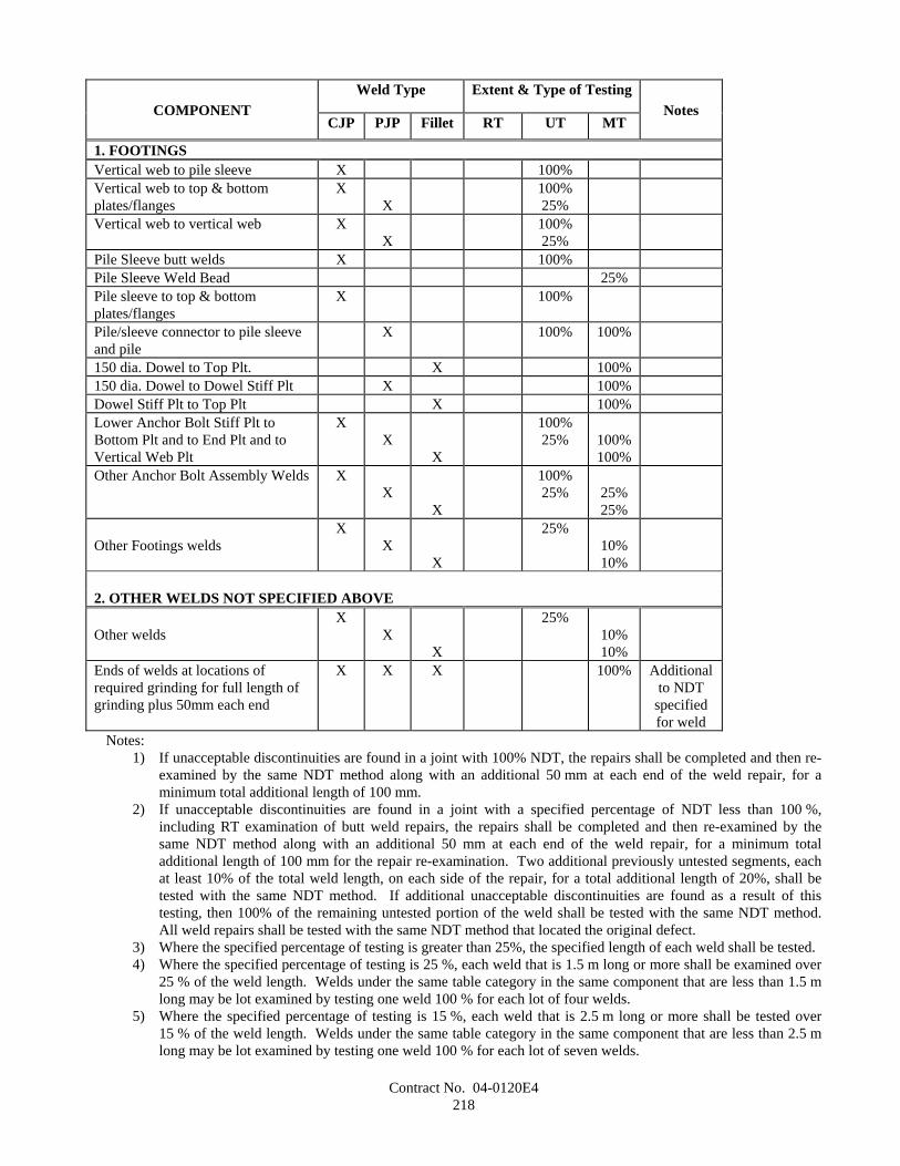
Contract No. 04-0120E4218
Weld Type Extent & Type of TestingCOMPONENT
CJP PJP Fillet RT UT MTNotes
1. FOOTINGSVertical web to pile sleeve X 100%Vertical web to top & bottomplates/flanges
XX
100%25%
Vertical web to vertical web XX
100%25%
Pile Sleeve butt welds X 100%Pile Sleeve Weld Bead 25%Pile sleeve to top & bottomplates/flanges
X 100%
Pile/sleeve connector to pile sleeveand pile
X 100% 100%
150 dia. Dowel to Top Plt. X 100%150 dia. Dowel to Dowel Stiff Plt X 100%Dowel Stiff Plt to Top Plt X 100%Lower Anchor Bolt Stiff Plt toBottom Plt and to End Plt and toVertical Web Plt
XX
X
100%25% 100%
100%Other Anchor Bolt Assembly Welds X
XX
100%25% 25%
25%
Other Footings weldsX
XX
25%10%10%
2. OTHER WELDS NOT SPECIFIED ABOVE
Other weldsX
XX
25%10%10%
Ends of welds at locations ofrequired grinding for full length ofgrinding plus 50mm each end
X X X 100% Additionalto NDT
specifiedfor weld
Notes:1) If unacceptable discontinuities are found in a joint with 100% NDT, the repairs shall be completed and then re-
examined by the same NDT method along with an additional 50 mm at each end of the weld repair, for aminimum total additional length of 100 mm.
2) If unacceptable discontinuities are found in a joint with a specified percentage of NDT less than 100 %,including RT examination of butt weld repairs, the repairs shall be completed and then re-examined by thesame NDT method along with an additional 50 mm at each end of the weld repair, for a minimum totaladditional length of 100 mm for the repair re-examination. Two additional previously untested segments, eachat least 10% of the total weld length, on each side of the repair, for a total additional length of 20%, shall betested with the same NDT method. If additional unacceptable discontinuities are found as a result of thistesting, then 100% of the remaining untested portion of the weld shall be tested with the same NDT method.All weld repairs shall be tested with the same NDT method that located the original defect.
3) Where the specified percentage of testing is greater than 25%, the specified length of each weld shall be tested.4) Where the specified percentage of testing is 25 %, each weld that is 1.5 m long or more shall be examined over
25 % of the weld length. Welds under the same table category in the same component that are less than 1.5 mlong may be lot examined by testing one weld 100 % for each lot of four welds.
5) Where the specified percentage of testing is 15 %, each weld that is 2.5 m long or more shall be tested over15 % of the weld length. Welds under the same table category in the same component that are less than 2.5 mlong may be lot examined by testing one weld 100 % for each lot of seven welds.
Contract No. 04-0120E4219
6) Where the specified percentage of testing is 10 %, each weld that is 4.0 m long or more shall be examined over10 % of the weld length. Welds under the same table category in the same component that are less than 4.0 mlong may be lot examined by testing one weld 100 % for each lot of ten welds.
7) For lot examination, if unacceptable discontinuities are found in the weld tested, the remainder of that weldshall be tested, and a second weld in the lot will be chosen by the Engineer and shall be tested. If unacceptablediscontinuities are found in the second weld, the entire lot shall be tested.
8) UT examination of PJP welds shall confirm the specified weld size and, for weld sizes greater than 15 mm,shall also evaluate the accessible weld volume to the requirements of AWS D1.5 for welds in compression.
9) Welds, and adjacent parent material within 10 mm of all accessible areas surrounding the weld, in grades withstrength levels of 485 and above shall be tested 100% by MT in addition to other specified inspection. Thetiming of visual and any method of NDT for welds in these steels shall be in accordance with AWS D1.5,Section 12.16.4.
10) Welds made by either the electroslag or electrogas processes shall be examined 100% by both radiographic andultrasonic testing.11) Scanning for ultrasonic examination of corner, tee and cruciform welds in thicknesses greater than 50 mm
shall include base metal behind and adjacent to the welds. Lamellar tearing discontinuities that exceed3 mm or that lie within 10 mm of the surface shall be repaired.
AcceptanceFor purposes of acceptance, all welds shall be considered to sustain tension, except for those otherwise shown on the
plans.UT examination of PJP welds shall confirm the specified weld size and, for weld sizes greater than 15 mm, shall also
evaluate the accessible weld volume to the requirements of AWS 1.5 for welds in tension.
FIELD WELDINGField fabricators shall be certified under the AISC Quality Certifications Program, Category CASE, Certified Advanced
Steel Erector.Field welding shall comply with all provisions under "Shop Welding," of these special provisions.The Contractor shall provide suitable enclosures to permit field welding during inclement weather, which includes local
wind speeds in the vicinity of the weld exceeding that specified in AWS D1.5, or 30 kilometer per hour, whichever is less.Provisions shall be made to control atmospheric conditions inside the enclosures with limits suitable for field welding inaccordance with the requirements of AWS D1.5 and "Welding " of these special provisions. Full compensation forproviding and maintaining such enclosures shall be considered as included in the contract prices paid for the various contractitems of work requiring field welding and no additional compensation will be allowed therefor.
No extension of contract time will be granted and no additional compensation will be allowed as a result of weatherconditions which exceed the limits for field welding designated herein, except as approved by the Engineer.
FIELD WELDING OF PILE/SLEEVE CONNECTOR PLATESField welding of pile/sleeve connector plates shall conform to the following requirements:
A. Stray current corrosion of the structure shall be avoided during installation at the site. Welding machines shall beplaced on the structure being welded. Where this is not practical, the insulated welded power source output"ground" lead shall be connected directly to the work at a location close to the weld being made and shall not bepermitted to touch the water. The minimum total cross sectional area of the return ground cable(s) shall be645 circular mm per 1000 amperes per 30.5 m of cable. Grounding sufficiency shall be periodically monitored bysimultaneously measuring the potential of the structure being welded and that holding the welding machines using astandard calomel electrode (SCE), Ag-AgCl or other reference electrode approved by the Engineer. A change inpotential reading of 10% or more shall indicate insufficient grounding.
B. Weld filler metal for the welding of Grade 345 shall conform to AWS D1.5, Table 4.1 or 4.2 and shall bedesignated H8 or less by the manufacturer. All welding consumables shall be heat or lot tested by the manufacturer,and certified test reports shall be submitted to the Engineer prior to being used.
C. Prequalified welding procedures are not permitted. All field welding procedures shall be qualified by testing asrequired by AWS D1.5 and these special provisions. Weld procedures shall be qualified and approved by theEngineer prior to welding any mock-up. Qualification tests shall include Charpy V-Notch tests of the weld metal.The tests shall meet the requirements of these special provisions.
D. Welding filler materials shall be considered an essential variable for welding procedure qualification. Any changein the filler material brand name, size or type requires requalification of the welding procedure.
Contract No. 04-0120E4220
E. GMAW shall not be used for field welding.F. The preheat and interpass temperature shall be in conformance with AWS D1.5, Section 12.14; and the minimum
preheat and interpass temperature shall be 65°C. In the event welding is interrupted, preheating to 65°C must occurbefore welding is resumed. For welds with required preheat temperatures greater than 65°C, preheat temperaturesshall be achieved and maintained using electric resistance heating bands for the entire length of the weld. Theheaters shall be controlled by attached thermocouples at spacing not exceeding 1 m. For these welds, the minimumpreheat temperature shall be maintained continuously from beginning to completion of the entire weld, even ifwelding is interrupted.
G. Welds shall not be water quenched. Welds shall be allowed to cool unassisted.H. Slots in the piles and pile sleeves shall be precision cut using mechanically-guided cutting equipment on tracks that
span the entire length of the cut. A hole shall be drilled at the bottom and top of each slot before cuttingcommences. Cut surfaces shall be protected as necessary to prevent gouging when cutting bevels in the slots.
Difficult access and working conditions are anticipated for field welding pile/sleeve connector plates. The Contractorshall construct mock-ups of the pile to footing connection in accordance with "Fabrication/Erection Procedure and Mock-Ups" above. The full-scale steel mock-up of the pile to footing sleeve connection shall demonstrate hole drilling, slotcutting, connection plate installation and fitting, welding and inspection. The Contractor shall perform qualification testingfor pile/sleeve connector plates in conformance with these special provisions.
The steel mock-up shall include the following details:
A. De-watering; method of attaching, sealing, drying, and protecting from welding and cutting sparks; method andplacement of de-watering equipment.
B. Pile/sleeve connector plate connections to the pile footing sleeve, including the method for installing the connectionplates.
The Engineer shall be given sufficient notice to witness all fit-up of the preliminary mock-up and fit-up and welding forthe steel mock-up.
tThe procedure shall describe the equipment and details for installing the seal, field cutting slots in the piles and sleeves,installing the connection plates and reinforcing steel, and performing all welding. The procedure shall describe the methodof dewatering the annulus between the pile and sleeve, including methods for accommodating worst case estimates ofleakage around the seals to ensure that the areas adjacent to all welding will be dry.
Welders and welding operators shall be qualified with similar access to that anticipated in the field and demonstrated inthe mock-up.
TestingThe completed steel mock-up assembly shall be examined visually and by MT, and by UT for complete and partial
penetration welds, using the nondestructive examination procedures proposed for production. The mock-up pile/sleeveconnector plate shall be sectioned and tested. Three macroetch specimens shall be removed from the welds between thepile/sleeve connector plate and the pile sleeve and between the pile/sleeve connector plate and the pile at locations indicatedby the Engineer. The size of the macroetch specimens shall be approved by the Engineer. Each specimen shall demonstratethe required weld size and weld profile. Qualification tests shall be adequate to:
A. Demonstrate the proposed installation procedure for each orientation of connection plate considering the leastfavorable combination of pile and footing fabrication and installation tolerances;
B. Demonstrate the welding sequence and verify the inspectability of each weld; andC. Where welding is anticipated on steel that will be submerged in water on the opposite side, confirm that satisfactory
welds can be made with the heat sink on the opposite side of the through plate. This confirmation weld shall be anadditional qualification test and PQR required to qualify welding procedures for this weld. The qualification weldshall be performed in accordance with the low heat input, low preheat temperature test piece per AWS D1.5,Section 5.12.2.2, except that the weld plate shall be artificially cooled. Sufficient water at the San Francisco Baywater temperature, or equivalent cooling as approved by the Engineer, shall be used as a heat sink to simulate theactual conditions. The procedure test piece shall be examined and tested per Test Plate A (Fig. 5.1) of AWS D1.5and these special provisions, including Charpy V-Notch tests of the weld.
The results of the mock-up procedure evaluation and weld procedure qualification tests shall be used to finalize thewritten installation and welding sequence procedure. The Contractor shall submit to the Engineer for approval, the written
Contract No. 04-0120E4221
installation and welding sequence procedure along with the final welding procedure and all procedure qualification records.The Contractor shall allow the Engineer 15 working days for review of the proposed procedure.
The procedure shall describe all equipment and temporary attachments to be used in installing the seal, footing,connection plates and other work to complete the installation of the footing. Approval of the installation and weldingsequence procedure shall be contingent on satisfactory results from the mock-up examination and destructive tests, asdetermined by the Engineer.
At completion of testing, all mock-ups shall become the property of the Contractor and shall be disposed of as providedin Section 7-1.13, "Disposal of Material Outside the Highway Right of Way," of the Standard Specifications.
Field welded pile/sleeve connector plates shall be inspected as follows:
A. The root pass shall be visually inspected before placing subsequent passes.B. The extent of non destructive testing shall be as specified under "Inspection and Testing" above. The acceptance
criteria shall conform to the requirements of AWS D1.5 for connections subject to tensile stress. UT and MT shallbe performed after the weld has cooled to ambient temperature in accordance with a written procedure that isapproved by the Engineer before use.
MEASUREMENT AND PAYMENTPayment for structural steel shall conform to the provisions in Section 55-4.02, "Payment," of the Standard
Specifications and these special provisions.Furnishing and erecting pile/sleeve connector plates will be measured and paid for as furnish structural steel (bridge) and
erect structural steel (bridge), respectively.Full compensation for all work specified under "TEMPLATE," of these special provisions shall be considered as
included in the contract price paid per kilogram for Furnish Structural Steel (Bridge).Full compensation for mock-ups and welding qualification procedures and testing shall be considered as included in the
contract price paid per kilogram for furnish structural steel (bridge) and no additional compensation will be allowed therefor.Full compensation for cutting slots in steel shells for pile/sleeve connector plates shall be considered as included in the
contract price paid per kilogram for erect structural steel (bridge) and no additional compensation will be allowed therefor.Full compensation for repairing damaged paint surfaces shall be considered as included in the contract price paid per
kilogram for erect structural steel (bridge) and no additional compensation will be allowed therefor.Full compensation for furnishing and bonding elastomeric pads to structural steel shall be considered as included in the
contract price paid per kilogram for furnish structural steel (bridge) and no additional compensation will be allowed therefor.Full compensation for furnishing and installing corrosion protective coverings and HDPE pipe, fittings, and grate,
including butt fusing pipe joints, shall be considered as included in the contract price paid per kilogram for furnish structuralsteel (bridge) and no additional compensation will be allowed therefor.
The sixth paragraph of Section 55-4.02 "Payment," of the Standard Specifications shall not apply.If a portion or all of the structural steel is fabricated more than 480 air line kilometers from both Sacramento and
Los Angeles, additional shop inspection expenses will be sustained by the State. Whereas it is and will be impracticable andextremely difficult to ascertain and determine the actual increase in these expenses, it is agreed that payment to theContractor for furnishing the structural steel from each fabrication site located more than 480 air line kilometers from bothSacramento and Los Angeles will be reduced $5000 or by an amount computed at $0.044 per kilogram of structural steelfabricated, whichever is greater, or in the case of each fabrication site located more than 4800 air line kilometers from bothSacramento and Los Angeles, payment will be reduced $8000 or by $0.079 per kilogram of structural steel fabricated,whichever is greater.
10-1.32 PLASTIC LUMBERThis work shall consist of furnishing and installing plastic lumber in conformance with the details shown on the plans
and these special provisions.
WORKING DRAWINGSThe Contractor shall submit working drawings for plastic lumber to the Engineer for approval in conformance with the
provisions in Working Drawings," of these special provisions.Working drawings shall show details for component layout and connections, the sequence of shop and field assembly,
and installation procedures. Working drawings shall be supplemented with the manufacturer's material test reports,manufacturer's performance data, material safety data sheets, and two copies of the printed literature for the product.
The Engineer will require 4 weeks to review the working drawings after a complete set has been received, as determinedby the Engineer. Fabrication of plastic lumber shall not commence until the working drawings are approved. The Engineerwill notify the Contractor in writing of approval of the working drawings. In the event the Engineer fails to complete the
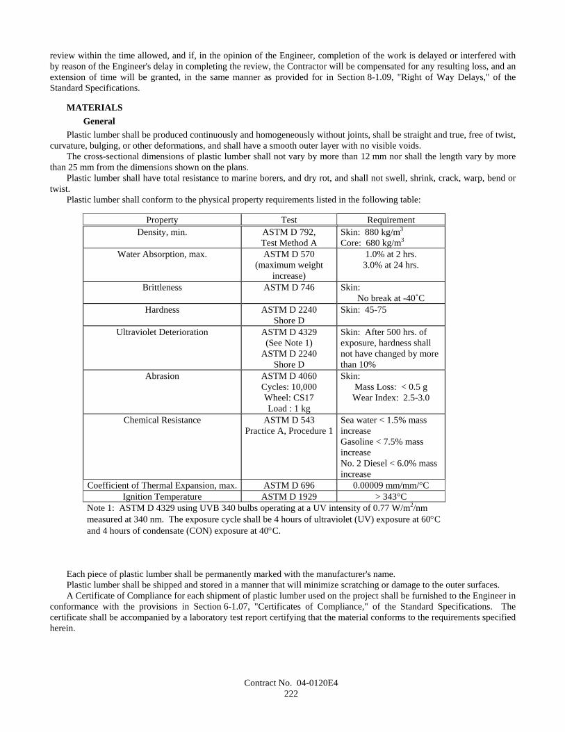
Contract No. 04-0120E4222
review within the time allowed, and if, in the opinion of the Engineer, completion of the work is delayed or interfered withby reason of the Engineer's delay in completing the review, the Contractor will be compensated for any resulting loss, and anextension of time will be granted, in the same manner as provided for in Section 8-1.09, "Right of Way Delays," of theStandard Specifications.
MATERIALSGeneral
Plastic lumber shall be produced continuously and homogeneously without joints, shall be straight and true, free of twist,curvature, bulging, or other deformations, and shall have a smooth outer layer with no visible voids.
The cross-sectional dimensions of plastic lumber shall not vary by more than 12 mm nor shall the length vary by morethan 25 mm from the dimensions shown on the plans.
Plastic lumber shall have total resistance to marine borers, and dry rot, and shall not swell, shrink, crack, warp, bend ortwist.
Plastic lumber shall conform to the physical property requirements listed in the following table:
Property Test RequirementDensity, min. ASTM D 792,
Test Method ASkin: 880 kg/m3
Core: 680 kg/m3
Water Absorption, max. ASTM D 570(maximum weight
increase)
1.0% at 2 hrs.3.0% at 24 hrs.
Brittleness ASTM D 746 Skin:No break at -40˚C
Hardness ASTM D 2240Shore D
Skin: 45-75
Ultraviolet Deterioration ASTM D 4329(See Note 1)
ASTM D 2240Shore D
Skin: After 500 hrs. ofexposure, hardness shallnot have changed by morethan 10%
Abrasion ASTM D 4060Cycles: 10,000Wheel: CS17Load : 1 kg
Skin:Mass Loss: < 0.5 gWear Index: 2.5-3.0
Chemical Resistance ASTM D 543Practice A, Procedure 1
Sea water < 1.5% massincreaseGasoline < 7.5% massincreaseNo. 2 Diesel < 6.0% massincrease
Coefficient of Thermal Expansion, max. ASTM D 696 0.00009 mm/mm/°CIgnition Temperature ASTM D 1929 > 343°C
Note 1: ASTM D 4329 using UVB 340 bulbs operating at a UV intensity of 0.77 W/m2/nmmeasured at 340 nm. The exposure cycle shall be 4 hours of ultraviolet (UV) exposure at 60°Cand 4 hours of condensate (CON) exposure at 40°C.
Each piece of plastic lumber shall be permanently marked with the manufacturer's name.Plastic lumber shall be shipped and stored in a manner that will minimize scratching or damage to the outer surfaces.A Certificate of Compliance for each shipment of plastic lumber used on the project shall be furnished to the Engineer in
conformance with the provisions in Section 6-1.07, "Certificates of Compliance," of the Standard Specifications. Thecertificate shall be accompanied by a laboratory test report certifying that the material conforms to the requirements specifiedherein.
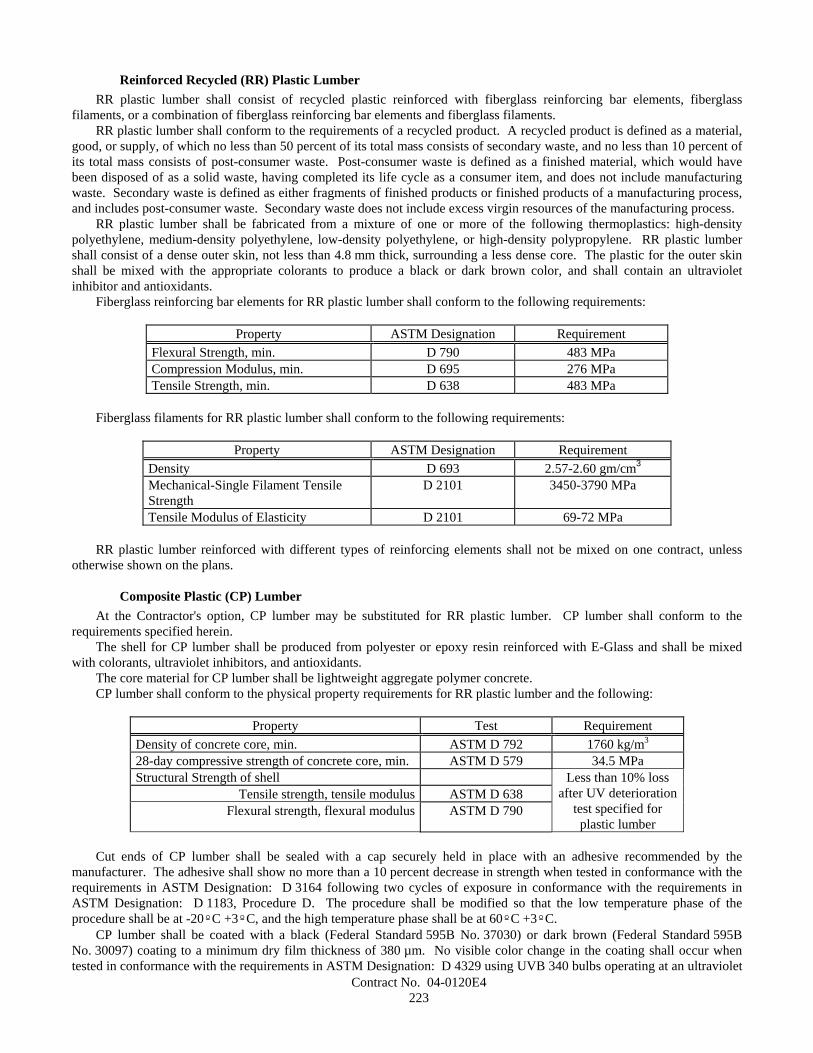
Contract No. 04-0120E4223
Reinforced Recycled (RR) Plastic LumberRR plastic lumber shall consist of recycled plastic reinforced with fiberglass reinforcing bar elements, fiberglass
filaments, or a combination of fiberglass reinforcing bar elements and fiberglass filaments.RR plastic lumber shall conform to the requirements of a recycled product. A recycled product is defined as a material,
good, or supply, of which no less than 50 percent of its total mass consists of secondary waste, and no less than 10 percent ofits total mass consists of post-consumer waste. Post-consumer waste is defined as a finished material, which would havebeen disposed of as a solid waste, having completed its life cycle as a consumer item, and does not include manufacturingwaste. Secondary waste is defined as either fragments of finished products or finished products of a manufacturing process,and includes post-consumer waste. Secondary waste does not include excess virgin resources of the manufacturing process.
RR plastic lumber shall be fabricated from a mixture of one or more of the following thermoplastics: high-densitypolyethylene, medium-density polyethylene, low-density polyethylene, or high-density polypropylene. RR plastic lumbershall consist of a dense outer skin, not less than 4.8 mm thick, surrounding a less dense core. The plastic for the outer skinshall be mixed with the appropriate colorants to produce a black or dark brown color, and shall contain an ultravioletinhibitor and antioxidants.
Fiberglass reinforcing bar elements for RR plastic lumber shall conform to the following requirements:
Property ASTM Designation RequirementFlexural Strength, min. D 790 483 MPaCompression Modulus, min. D 695 276 MPaTensile Strength, min. D 638 483 MPa
Fiberglass filaments for RR plastic lumber shall conform to the following requirements:
Property ASTM Designation RequirementDensity D 693 2.57-2.60 gm/cm3
Mechanical-Single Filament TensileStrength
D 2101 3450-3790 MPa
Tensile Modulus of Elasticity D 2101 69-72 MPa
RR plastic lumber reinforced with different types of reinforcing elements shall not be mixed on one contract, unlessotherwise shown on the plans.
Composite Plastic (CP) LumberAt the Contractor's option, CP lumber may be substituted for RR plastic lumber. CP lumber shall conform to the
requirements specified herein.The shell for CP lumber shall be produced from polyester or epoxy resin reinforced with E-Glass and shall be mixed
with colorants, ultraviolet inhibitors, and antioxidants.The core material for CP lumber shall be lightweight aggregate polymer concrete.CP lumber shall conform to the physical property requirements for RR plastic lumber and the following:
Property Test RequirementDensity of concrete core, min. ASTM D 792 1760 kg/m3
28-day compressive strength of concrete core, min. ASTM D 579 34.5 MPaStructural Strength of shell
Tensile strength, tensile modulus ASTM D 638Flexural strength, flexural modulus ASTM D 790
Less than 10% lossafter UV deterioration
test specified forplastic lumber
Cut ends of CP lumber shall be sealed with a cap securely held in place with an adhesive recommended by themanufacturer. The adhesive shall show no more than a 10 percent decrease in strength when tested in conformance with therequirements in ASTM Designation: D 3164 following two cycles of exposure in conformance with the requirements inASTM Designation: D 1183, Procedure D. The procedure shall be modified so that the low temperature phase of theprocedure shall be at -20ºC +3ºC, and the high temperature phase shall be at 60ºC +3ºC.
CP lumber shall be coated with a black (Federal Standard 595B No. 37030) or dark brown (Federal Standard 595BNo. 30097) coating to a minimum dry film thickness of 380 µm. No visible color change in the coating shall occur whentested in conformance with the requirements in ASTM Designation: D 4329 using UVB 340 bulbs operating at an ultraviolet
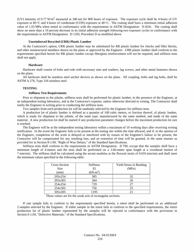
Contract No. 04-0120E4224
(UV) intensity of 0.77 W/m2 measured at 340 nm for 800 hours of exposure. The exposure cycle shall be 4 hours of UVexposure at 60ºC and 4 hours of condensate (CON) exposure at 40ºC. The coating shall have a minimum initial adhesionvalue of 1.03 MPa when tested in conformance with the requirements in ASTM Designation: D 4541. The coating shallshow no more than a 10 percent decrease in its initial adhesion strength following two exposure cycles in conformance withthe requirements in ASTM Designation: D 1183, Procedure D as modified above.
Unreinforced Recycled (URR) Plastic LumberAt the Contractor's option, URR plastic lumber may be substituted for RR plastic lumber for chocks and filler blocks,
and other nonstructural members shown on the plans or approved by the Engineer. URR plastic lumber shall conform to therequirements specified herein for RR plastic lumber except fiberglass reinforcement will not be required, and stiffness testsshall not apply.
HardwareHardware shall consist of bolts and rods with necessary nuts and washers, lag screws, and other metal fasteners shown
on the plans.All hardware shall be stainless steel anchor devices as shown on the plans. All coupling, bolts and lag bolts, shall be
ASTM A 276, Type 316 stainless steel.
TESTINGStiffness Test Requirements
Prior to shipment to the jobsite, stiffness tests shall be performed for plastic lumber, in the presence of the Engineer, atan independent testing laboratory, and at the Contractor's expense, unless otherwise directed in writing. The Contractor shallnotify the Engineer in writing prior to conducting the stiffness tests.
Two samples from each production lot will be randomly selected by the Engineer for stiffness tests.A production lot of plastic lumber is defined as a quantity of 100 cubic meters, or fraction thereof, of plastic lumber,
which is ready for shipment to the jobsite, of the same type, manufactured by the same method, and made of the samematerial. A new production lot shall be started if any production parameter changes before the maximum production lot sizeis reached.
The Engineer will be at the independent testing laboratory within a maximum of 10 working days after receiving writingnotification. In the event the Engineer fails to be present at the testing site within the time allowed, and if, in the opinion ofthe Engineer, completion of the work is delayed or interfered with by reason of the Engineer's failure to be present, theContractor will be compensated for any resulting loss, and an extension of time will be granted, in the same manner asprovided for in Section 8-1.09, "Right of Way Delays," of the Standard Specifications.
Stiffness tests shall conform to the requirements in ASTM Designation: D 790, except that the samples shall have aminimum length of 4 meters and the tests shall be performed on a 3.66-meter span length at a crosshead motion of7 mm/min. The stiffness shall be calculated using the secant modulus at the flexural strain of 0.010 mm/mm and shall meetthe minimum values specified in the following table:
Cross SectionSize(mm)
StiffnessEI
(kN-m2)
Yield Stress in Bending(MPa)
203x254 385 32203x305 364 26254x254 729 27254x305 756 25305x305 1195 21
These values are for the weak axis of rectangular sections.
If one sample fails to conform to the requirements specified herein, a retest shall be performed on an additional2 samples selected by the Engineer. If either sample in the retest fails to conform to the specified requirements, the entireproduction lot of plastic lumber represented by the samples will be rejected in conformance with the provisions inSection 6-1.04, "Defective Materials," of the Standard Specifications.
Contract No. 04-0120E4225
Void Test RequirementsPrior to use in the work, 2 samples of each size from each lot of plastic lumber delivered to the jobsite, or a quantity of
100 cubic meters, or fraction thereof, of said plastic lumber, whichever is smaller, will be selected by the Engineer for voidtests.
The samples will be examined by the Engineer for exterior voids first. The exterior voids shall conform to the followingrequirements:
A. The maximum dimension of any void at each exposed end shall not exceed 25 mm.B. The total number of voids with a maximum dimension greater than 6 mm at each exposed end shall not exceed 4.
If a sample examined for exterior voids fails to conform to either requirement above, a retest shall be performed on anadditional 2 samples selected by the Engineer. If either sample in the retest fails to conform to either requirement, the entirelot of plastic lumber represented by the samples will be rejected in conformance with the provisions in Section 6-1.04,"Defective Materials," of the Standard Specifications.
After passing the requirements above, the samples are to be cut into 305-mm long segments by the Contractor andexamined for interior voids by the Engineer. The cut sections of each segment shall conform to the following requirements:
D. The maximum dimension of any void in a cut section shall not exceed 12 mm.E. The total area of voids in a cut section shall not exceed 5 percent of the total cross-sectional area.
If a cut section examined for interior voids fails to conform to either requirement above, a retest shall be performed onan additional 2 samples selected by the Engineer. If a cut section in the retest fails to conform to either requirement, theentire lot of plastic lumber represented by the samples will be rejected in conformance with the provisions in Section 6-1.04,"Defective Materials," of the Standard Specifications.
Test results will be reported in writing to the Contractor within 10 working days after receipt of the samples by theEngineer. In the event the Engineer fails to provide the test results within the time allowed, and if, in the opinion of theEngineer, completion of the work is delayed or interfered with by reason of the Engineer's delay in providing the results, theContractor will be compensated for any resulting loss, and an extension of time will be granted, in the same manner asprovided for in Section 8-1.09, "Right of Way Delays," of the Standard Specifications.
All samples for stiffness and void tests shall be furnished by the Contractor at the Contractor's expense.
CONSTRUCTIONPlastic lumber shall be installed in conformance with the manufacturer's recommendations and these special provisions.Plastic lumber shall be stacked on dunnage above ground so that it may be readily inspected and shall be stored and
handled in a manner that will avoid damage, breakage, or other deformations. The lumber shall be protected from the sun toprevent warping.
Plastic lumber shall be cut, beveled, drilled, counterbored, and otherwise fabricated in conformance with themanufacturer's recommendations, and as shown on the plans. Fabrication shall be done in the manufacturer's facilities to thegreatest extent possible.
Unless otherwise shown on the plans, holes for bolts in the plastic lumber shall be bored 3 mm larger in diameter thanthe bolt to be placed. Holes for lag screws shall be bored to a diameter in conformance with the manufacturer'srecommendations. Bolts and lag screw heads shall be recessed 12 mm from the surface of the face of the plastic lumberfender or as shown on the plans.
Holes drilled through CP lumber members shall be coated with a concrete sealant conforming to the manufacturer'srecommendations.
Plastic lumber elements that are split, broken, warped, or otherwise damaged will be rejected and replaced at theContractor's expense.
MEASUREMENT AND PAYMENTPlastic lumber will be measured by the cubic meter. The quantity to be paid for shall be determined from nominal
widths and thicknesses and the actual lengths of the pieces in the finished assembly as shown on the plans.The contract price paid per cubic meter for plastic lumber shall include full compensation for furnishing all labor,
materials (including hardware), tools, equipment, and incidentals, and for doing all the work involved in furnishing andinstalling plastic lumber, complete in place, as shown on the plans, as specified in the Standard Specifications and thesespecial provisions, and as directed by the Engineer.
Contract No. 04-0120E4226
10-1.33 ULTRA HIGH MOLECULAR WEIGHT POLYETHYLENE PANELUltra High Molecular Weight (UHMW) polyethylene panel shall consist of furnishing and installing UHMW panels and
shall conform to the details shown on the plans and these special provisions.
MATERIALSThe UHMW panels shall be manufactured with a maximum 50 percent regenerated or recycled material; and with a
molecular weight of 3,000,000 to 6,000,000 in accordance with ASTM Designation: D 4020, compression molded, stressrelieved, and including an ultraviolet stabilizer. The color of the panels shall be black. The UHMW shall be approved bythe Engineer. Physical characteristics shall conform to the following requirements:
A. Static coefficient of friction to steel (dry) shall be less than 0.025.B. Specific gravity shall be greater than 0.92 (ASTM Designation: D 792)C. No water absorption shall be shown under long term immersion (ASTM Designation: D 510)D. The minimum tensile stress capacity shall be 25 MPa and the minimum impact shear capacity shall be 10 MPa.
The UHMW panels shall be anchored to the in-place, plastic lumber fender walers using stainless steel anchor devices asshown on the plans. All couplings, bolts, and lag bolts shall be ASTM Designation: A 276, Type 316 stainless steel.
CONSTRUCTIONThe UHMW panels shall be delivered to the site and stored in a manner that will prevent damage to the panels. A
Certificate of Compliance conforming to the provisions in Section 6-1.07, "Certificates of Compliance," of the StandardSpecifications, shall be furnished for each shipment of UHMW panels certifying that the material and workmanshipconforms to the requirements in ASTM Designation: D 4020 and these special provisions. Two copies of the certificationsfrom the manufacturer shall be furnished to the Engineer. Materials without manufacturer’s certification will be rejected.
Immediately prior to installation, the Contractor shall inspect the panels for damage and the results of the inspectionshall be reported to the Engineer. Materials which, in the Engineer’s opinion, are defective or damaged, shall be repaired orreplaced in kind by the Contractor at the Contractor’s expense.
All lag screw heads shall be countersunk flush with the surface of the UHMW panels. All lag screw locations shall bepre-drilled into the receiving plastic lumber walers with bits having the same diameter as the bolt shank.
The minimum clear distance from the heads of all lag screws to the end or edge of the plastic lumber walers shall be 50mm. The minimum edge distance from the centerline of lag screws to the edge of a UHMW panel shall be 50 mm.
UHMW panels shall be installed abutting each other with a 6.5 mm gap between two panels and all joints betweenpanels shall be flush.
UHMW panels at all corners shall be constructed of a single unit formed by heat bending in accordance with themanufacturer’s recommendations. Butt joints at corner locations will not be permitted.
MEASUREMENT AND PAYMENTUHMW polyethylene panels will be measured by the square meter.The contract price paid per square meter for UHMW polyethylene panel (50 mm) shall include full compensation for
furnishing all labor, materials, tools, equipment, and incidentals and for doing all the work involved in constructing UHMWpolyethylene panel, complete in place, as shown on the plans, as specified in the Standard Specifications and these specialprovisions, and as directed by the Engineer.
10-1.34 CLEAN AND PAINT STRUCTURAL STEELExposed new metal surfaces, except where galvanized, shall be cleaned and painted in conformance with the provisions
in Section 59-2, "Painting Structural Steel," and Section 91, "Paint," of the Standard Specifications and these specialprovisions.
Prior to performing any painting or paint removal, the Contractor shall submit to the Engineer, in conformance with theprovisions in Section "Working Drawings," of these special provisions, 3 copies of a separate Painting Quality Work Plan(PQWP) for each item of work for which painting or paint removal is to be performed. As a minimum, each PQWP shallinclude the following:
A. The name of each Contractor or subcontractor to be used.B. One copy each of all current "SSPC: The Society for Protective Coatings" specifications or qualification procedures
which are applicable to the painting or paint removal to be performed. These documents shall become thepermanent property of the Department.
Contract No. 04-0120E4227
C. Proposed methods and equipment to be used for any paint application.D. Proof of each of any required certifications, SSPC-QP 1, SSPC-QP 2, SSPC-QP 3.
The Engineer shall have 14 working days to review the PQWP submittal after a complete plan has been received. Nopainting or paint removal shall be performed until the PQWP for that work is reviewed by the Engineer.
CLEANINGExposed new metal surfaces shall be dry blast cleaned in conformance with the requirements in Surface Preparation
Specification No. 10, "Near White Blast Cleaning," of the "SSPC: The Society for Protective Coatings." Blast cleaning shallleave surfaces with a dense, uniform, angular anchor pattern of not less than 40 µm nor more than 86 µm as measured inconformance with the requirements in ASTM Designation: D 4417.
Mineral and slag abrasives used for blast cleaning steel shall conform to the requirements in Abrasive SpecificationNo. 1, "Mineral and Slag Abrasives," of the "SSPC: The Society for Protective Coatings" and shall not contain hazardousmaterial. Mineral and slag abrasives shall comply with the requirements for Class A, Grade 2 to 3 as defined therein.
A Certificate of Compliance conforming to the provisions in Section 6-1.07, "Certificates of Compliance," of theStandard Specifications and a Material Safety Data Sheet shall be furnished prior to use for each shipment of blast cleaningmaterial for steel.
PAINTINGBlast cleaned surfaces shall receive a single undercoat, and a final coat where specified, consisting of a waterborne
inorganic zinc coating conforming to the requirements in AASHTO Designation M 300, Type II, except that: 1) the first3 sentences of Section 4.7, "Primer Field Performance Requirements," and the entire Section 4.7.1 shall not apply, and2) zinc dust shall be Type II in conformance with the requirements in ASTM Designation: D 520. The inorganic zinccoating shall be listed on the qualified products list which may be obtained from the Transportation Laboratory.
The color of the final application of inorganic zinc coating shall match Federal Standard 595B No. 36373.Inorganic zinc coating shall be used within 12 hours of initial mixing.Application of inorganic zinc coating shall conform to the provisions for applying zinc-rich coating in Section 59-2.13,
"Application of Zinc-Rich Primer," of the Standard Specifications.Inorganic zinc coating shall not be applied when the atmospheric or surface temperature is less than 7°C or more than
29°C, nor when the relative humidity exceeds 85 percent.The single undercoat of inorganic zinc coating shall be applied to the required dry film thickness in 2 or more
applications within 4 hours after blast cleaning.The total dry film thickness of all applications of the inorganic zinc undercoat, including the surfaces of outside existing
members within the grip under bolt heads, nuts and washers, shall be not less than 100 µm nor more than 200 µm, exceptthat the total dry film thickness on each faying (contact) surface of high strength bolted connections shall be between 25 µmand the maximum allowable dry film thickness for Class B coatings as determined by certified testing in conformance withAppendix A of the "Specification for Structural Joints Using ASTM A325 or A490 Bolts" of the Research Council onStructural Connections (RCSC Specification). Unless otherwise stated, all inorganic zinc coatings used on faying surfacesshall meet the slip coefficient requirements for a Class B coating on blast-cleaned steel, as specified in the RCSCSpecification. The Contractor shall provide results of certified testing showing the maximum allowable dry film thicknessfor the Class B coating from the qualifying tests for the coating he has chosen, and shall maintain the coating thickness onactual faying surfaces of the structure at or below this maximum allowable coating thickness.
Areas where mudcracking occurs in the inorganic zinc coating shall be blast cleaned and repainted with inorganic zinccoating to the specified thickness.
Dry spray, or overspray, as defined in the Steel Structures Painting Manual, Volume 1, "Good Painting Practice," of the"SSPC: The Society for Protective Coatings," shall be removed prior to application of subsequent coats or final acceptance.Removal of dry spray shall be by screening or other methods that minimize polishing of the inorganic zinc surface. The dryfilm thickness of the coating after removal of dry spray shall be in conformance with the provisions for applying the singleundercoat, as specified herein.
The inorganic zinc coating shall be tested for adhesion and cure. The locations of the tests will be determined by theEngineer. The sequence of the testing operations shall be determined by the Contractor. The testing for adhesion and curewill be performed no sooner than 72 hours after application of the single undercoat of inorganic zinc coating. At theContractor's expense, satisfactory access shall be provided to allow the Engineer to determine the location of the tests and totest the inorganic zinc coating cure. The inorganic zinc coating shall pass the following tests:
Contract No. 04-0120E4228
Adhesion• The inorganic zinc coating shall have a minimum adhesion to steel of 4 MPa when measured at no more than
6 locations per span on each girder using a self-aligning adhesion tester in conformance with the requirements inASTM Designation: D 4541. The Contractor, at the Contractor's expense, shall: (1) verify compliance with theadhesion requirements, (2) furnish test results to the Engineer, and (3) repair the coating after testing.
Cure• The inorganic zinc coating, when properly cured, shall exhibit a solid, hard, and polished metal surface when firmly
scraped with the knurled edge of a quarter. Inorganic zinc coating that is powdery, soft, or does not exhibit apolished metal surface, as determined by the Engineer, shall be repaired by the Contractor, at the Contractor'sexpense, by blast cleaning and repainting with inorganic zinc coating to the specified thickness.
Finish coats will not be required.
10-1.35 MISCELLANEOUS METAL (BRIDGE)Miscellaneous metal (bridge) shall conform to the provisions for miscellaneous bridge metal in Section 75,
"Miscellaneous Metal," of the Standard Specifications and these special provisions.Attention is directed to "Welding" of these special provisions.Miscellaneous metal (bridge) shall consist of the miscellaneous bridge metal items listed in Section 75-1.03,
"Miscellaneous Bridge Metal," of the Standard Specifications, and the following:
A. Steel downhole casing EB. Fender ladders
Cast-in-place inserts shall be the ferrule loop type.Metal parts of concrete anchorage devices shall be fabricated from stainless steel conforming to the requirements of
ASTM Designation: A 276, Type 316.The downhole casing shall be installed securely at the location shown on the plans. The Contractor shall notify the
Engineer not less than 15 working days prior to installing the downhole casing.The contract lump sum price paid for furnish and install steel downhole casing E shall include full compensation for
furnishing all labor, materials, tools, equipment, and incidentals and for doing all the work involved in furnishing andinstalling the steel downhole casing, complete in place, as shown on the plans, as specified in the Standard Specifications andthese special provisions, and as directed by the Engineer.
NONSKID SURFACEWhere shown on the plans, fender ladders shall receive a nonskid surface consisting of epoxy mixed with grit. Epoxy
shall conform to the provisions in Section 95, "Epoxy," of the Standard Specifications.Epoxy shall consist of epoxy conforming to the provisions in either Section 95-2.01, "Binder (Adhesive), Epoxy Resin
Base (State Specification 8040-01F-03)," or Section 95-2.09, "Epoxy Sealant for Inductive Loops (State Specification8040-31D-06)," of the Standard Specifications.
Grit shall consist of commercial quality aluminum oxide, silicon carbide, or almandite garnet grit particles, screen size1.7 m to 600 µm or 1.4 m to 500 µm, applied uniformly at the rate of at least 1.5-kg per square meter of surface area.
The finish color of the nonskid surface shall be light gray.The Contractor shall submit to the Engineer for approval a method of application stating the spread rate of epoxy and
grit and the number of coats. The Contractor shall demonstrate the method of application to the Engineer, prior to placingany nonskid material, by preparing a 0.1 square meter sample placed on 6 mm minimum thickness hardboard. The nonskidsurface shall have a total thickness of between 3 mm and 5 mm.
At the option of the Contractor, a commercial quality nonskid surface, comprised of a 2-component ultra violet resistantepoxy and grit of quality equal to the above requirements, may be submitted to the Engineer for approval.
Full compensation for furnishing, installing, and painting structural steel for stair framing supports and for furnishingand placing nonskid surface shall be considered as included in the contract price paid per kilogram for miscellaneous metal(bridge) and no separate payment will be made therefor.
Contract No. 04-0120E4229
10-1.36 CHAIN LINK FENCEChain link fence shall be Type CL 1.8 and shall conform to the provisions in Section 80, "Fences," of the Standard
Specifications.
10-1.37 CONCRETE BARRIER (TYPE K)Concrete barrier (Type K) shall conform to the provisions in Section 83-2, "Barriers," of the Standard Specifications and
these special provisions.Concrete barrier (Type K) shall consist of precast units conforming to the provisions for temporary railing (Type K) in
Section 12-3.08, "Temporary Railing (Type K)," of the Standard Specifications, except that removable panels shall not beused and the concrete barrier (Type K) shall remain in place at the completion of the contract.
Temporary railing (Type K) reflectors on concrete barrier (Type K) shall conform to the provisions in "Prequalified andTested Signing and Delineation Materials" of these special provisions.
Full compensation for furnishing and installing temporary railing (Type K) reflectors on concrete barrier (Type K) shallbe considered as included in the contract price paid per meter for concrete barrier (Type K) and no additional compensationwill be allowed therefor.
SECTION 10-2. (BLANK)
SECTION 10-3. ELECTRICAL SYSTEMS
10-3.01 DESCRIPTIONGrounding for Piers E2 and T1 foundations, furnishing and installing downhole enclosure, installing steel cap assembly
for strong motion detection system, furnishing and installing navigation lighting system and furnishing and installing pilecorrosion monitoring system shall conform to the provisions in Section 86, "Signals, Lighting and Electrical Systems," of theStandard Specifications and these special provisions.
10-3.02 GROUNDING FOR PIERS E2 AND T1 FOUNDATIONSThe electrical work shall consist of installing grounding conductors in Piers E2 and T1 foundations. The work shall be
performed in accordance with the plans, Standard Specifications, and as specified in these special provisions.
REFERENCESThe regulatory requirements which govern the work of this section include the following governing codes and standards:
A. American Society for Testing and Materials (ASTM):
1. ASTM Designation: B-3, Soft or Annealed Copper Wire.2. ASTM Designation: B-8, Concentric-Lay Stranded Copper Conductors.3. ASTM Designation: B-33, Tinned Soft or Annealed Copper Wire for Electrical Purposes.
B. Federal Specification QQ-W-343, latest revision, Wire, Electrical, Copper, Uninsulated.
SUBMITTALS
Product data. Submit Manufacturer's descriptive data and installation instructions for all products and equipmentfurnished and installed under this contract for approval.
Certified Test Reports. Submit with material.
MATERIALS
Grounding Conductors. Grounding conductors shall be stranded soft drawn bare copper meeting the requirements ofthe ASTM Specifications.
Ground Connections. All ground connections shall be of the exothermic type.
Contract No. 04-0120E4230
EXECUTIONUnless otherwise shown on the plans, install all products, equipment and accessories in accordance with the
manufacturer's instructions.
MEASUREMENTGrounding for Piers E2 and T1 foundations will be paid for on a lump sum basis.
10-3.03 STRONG MOTION DETECTION DOWNHOLEThe electrical work shall consist of furnishing and installing downhole enclosure, and installing sealed cap assembly
furnished by California Division of Mine and Geology (CDMG) for the strong motion detection system on pier T1foundation. The work shall be performed as shown on the plans, Standard Specifications and as specified in these specialprovisions.
Downhole seismic sensor cable (SSC) will be furnished and installed by CDMG.
MATERIAL
1. State-furnished MaterialThe sealed cap assembly will be State-furnished as provided under "Materials" of these special provisions.
2. Downhole EnclosureThe Contractor shall provide downhole enclosure (protective box) with bolt down type lid as shown on the plans.
Downhole enclosure and lid shall be of fibrelyte materials. The box and lid shall be manufactured by Christy, or otherapproved manufacturer.
EXECUTIONUnless otherwise shown on the plans, install all products, equipment and accessories in accordance with the
manufacturer's instructions.
MEASUREMENTStrong motion detection downhole for T1 foundation will be paid for on a lump sum basis.
10-3.04 NAVIGATION LIGHTING SYSTEM The work shall include furnishing and installing navigation lighting system at Piers E2 and T1 foundations. The work
shall be performed as shown on the plans, Standard Specifications and as specified in these special provisions.
SUBMITTALS
Product data. Submit manufacturer's descriptive data and installation instructions for all products and equipmentfurnished and installed under this contract for approval.
Working Drawings. Submit working drawings showing the attachment details to the lighting assembly.
Certified Test Reports. Submit with material.
MATERIALS
Navigational LightThe navigational light shall be manufactured by Automatic Power Inc., or other approved manufacturer.
Steel Mast and Mounting PlateSteel mast and mounting plate shall conform to the requirements in Section 75, "Miscellaneous Metal," of the Standards
Specifications, except for payment.
Navigation Lighting Equipment
Contract No. 04-0120E4231
Navigation lighting equipment shall have the following characteristics conforming to the U.S. Coast Guard and Code ofFederal Regulations, Title 33, Section 64 and all of their applicable codes:
A. 360 degree all around white light.B. Light shall be designed to emit 15 flashes per minute.C. Emitted light shall be visible a minimum of 4.8 kilometers (3 miles).D. Lighting assembly shall have a marine-quality tamper-proof hardware, encapsulated and waterproof, resistant to UV
light, impact resistant polycarbonate lens and shall be solar power.E. Lighting assembly shall be guaranteed to fully operate maintenance free for minimum of 3 years from the date of
acceptance.F. Lighting assembly shall utilize an LED lamp, a solar panel (minimum 12 V) and a re-charging battery (minimum 12
V) for energy storage. Lamp, storage battery and controls shall be contained in the same housing.G. Lighting assembly shall operate minimum of 5 days in total darkness and at least 10 days in over cast conditions. It
shall flash at night and during periods of insufficient sunlight and shall be controlled by a photoelectric device.
EXECUTIONUnless otherwise shown on the plans, install all products, equipment and accessories in accordance with the
manufacturer's instructions.The navigational lighting assemblies shall be attached to the supporting masts either by bolting, or threaded attachments.After the completion of this contract the navigation lighting system shall stay operational to be maintained by others.
MEASUREMENTNavigation lighting system for Piers E2 and T1 will be paid for on a lump sum basis.
10-3.05 PILE CORROSION MONITORING SYSTEMSteel pile corrosion monitoring system and the connection for the future pile corrosion protection system shall conform
to the provisions in this special provision.
STANDARDSThe Contractor shall install each system component in conformance with the latest edition of the following standards:
1. STDS State of California Standard Specifications2. NEMA National Electrical Manufacturers Association3. ASTM American Society for Testing and Materials4. IEEE Institute of Electrical and Electronic Engineers5. ANSI American National Standard Institute6. ICEA Insulated Cable Engineers Association7. OSHA Occupational Safety and Health Administration8. NACE National Association of Corrosion Engineers9. UL Underwriters Laboratories
SUBMITTALSThe following manufacturer's data shall be submitted:
1. Catalog cuts, bulletins, brochures or data sheets for all equipment.2. Certification that the equipment and materials proposed meet the requirements of this special provision.
Corrosion Monitoring System SubmittalThe Contractor's corrosion monitoring system working drawings shall include an installation schedule for the ultrasonic
thickness probe system.Prior to installing the ultrasonic thickness probes the Contractor shall provide a corrosion monitoring system submittal
for the attachment procedure in conformance with this special provision.The corrosion system submittal shall be stamped and signed by an engineer who is registered as a Corrosion Engineer in
the State of California. The Contractor shall allow the Engineer 42 working days to review the submittal after a complete sethas been received, as determined by the Engineer, and prior to installation. Should the Engineer fail to complete his reviewwithin the time allowance, and if, in the opinion of the Engineer, the Contractor's controlling operation is delayed or
Contract No. 04-0120E4232
interfered with by reason of the delay in the driving system submittal review, the delay will be considered a right of waydelay in conformance with the provisions in Section 8-1.07, "Liquidated Damages," in the Standard Specifications.
Ultrasonic Thickness ProbeThe ultrasonic thickness transducers to be installed on the interior surface of the steel pile on Piers T1 and E2 shall be an
Accuscan, Lemo Connector Type, Transducer Part Number D790 manufactured by RT transducers distributed byPanametrics, or approved equal. Cable shall be as supplied by manufacturer for the intended use. The probes are to beinstalled permanently inside the pile shell and set in epoxy after the reinforcing cage is installed and before the tremieconcrete is placed. Wiring shall be set in epoxy on the shell wall, or installed in a small conduit and sealed in silicone gel.
This system is to be installed in one pile at each of two piers at the depths shown on the plans. Specific details of theprobe, the required wiring and the associated terminal sockets shall be provided by the corrosion consultant. The terminalconnectors shall be hermetically sealed BNC female to male adapters, Model 3847, or equal. The length of cable shall beless than 30 meters.
Connection for Future Pile Corrosion ProtectionThe terminal located inside a hollow pier at T1, or adjacent to a solid pier at E2 shall provide an electrical connection to
the steel pile cap frame that is set inside the concrete pile cap. The steel frame is electrically connected to the steel pile shellsby welded steel plates to permit the connection of an impressed current cathodic protection system in the future.
The Contractor's working drawings for the connection for future pile corrosion protection system shall include a listingof all materials to be used and a statement that meets the requirements of this special provision.
Prior to installing the connections at any given pier the Contractor shall provide a submittal for attaching the negativetest lead, in conformance with this special provision.
Connection terminal boxes shall be installed at the approximate location shown on the plans. The Contractor shall fieldverify final location of the test stations. Wire identifiers shall be placed on all wire prior to installation of test boxes.
MEASUREMENTPile corrosion monitoring system (for Piers T1 and E2 foundations) will be paid for on a lump sum basis.
10-3.06 PAYMENTThe contract lump sum price paid for grounding for Piers E2 and T1 foundations shall include full compensation for
furnishing all labor, materials, tools, equipment, and incidentals and for doing all the work involved in grounding for PiersE2 and T1 foundations, complete in place, as shown on the plans, as specified in the Standard Specifications and thesespecial provisions, and as directed by the Engineer.
The contract lump sum price paid for strong motion detection downhole (for Pier T1) shall include full compensation forfurnishing all labor, materials, tools, equipment, and incidentals and for doing all the work involved in strong motiondetection downhole, as shown on the plans, as specified in the Standard Specifications and these special provisions, and asdirected by the Engineer.
The contract lump sum price paid for installing navigation lighting system shall include full compensation for furnishingall labor, materials, tools, equipment, and incidentals and for doing all the work involved in installing navigation lightingsystem complete in place, as shown on the plans, as specified in the Standard Specifications and these special provisions, andas directed by the Engineer.
The contract lump sum price paid for pile corrosion monitoring system shall include full compensation for furnishing alllabor, materials, tools, equipment, and incidentals and for doing all the work involved in pile corrosion monitoring systemfor Piers T1 and E2 foundations, complete in place, as shown on the plans, as specified in the Standard Specifications andthese special provisions, and as directed by the Engineer.
SECTION 11. (BLANK)
SECTION 12. (BLANK)
SECTION 13. (BLANK)
Contract No. 04-0120E4233
SECTION 14 FEDERAL REQUIREMENTS FOR FEDERAL-AID CONSTRUCTIONPROJECTS
GENERAL.—The work herein proposed will be financed in whole or in part with Federal funds, and therefore all ofthe statutes, rules and regulations promulgated by the Federal Government and applicable to work financed in whole or inpart with Federal funds will apply to such work. The "Required Contract Provisions, Federal-Aid Construction Contracts,"Form FHWA 1273, are included in this Section 14. Whenever in said required contract provisions references are made to"SHA contracting officer", "SHA resident engineer", or "authorized representative of the SHA", such references shall beconstrued to mean "Engineer" as defined in Section 1-1.18 of the Standard Specifications.
PERFORMANCE OF PREVIOUS CONTRACT.—In addition to the provisions in Section II, "Nondiscrimination,"and Section VII, "Subletting or Assigning the Contract," of the required contract provisions, the Contractor shall complywith the following:
The bidder shall execute the CERTIFICATION WITH REGARD TO THE PERFORMANCE OF PREVIOUSCONTRACTS OR SUBCONTRACTS SUBJECT TO THE EQUAL OPPORTUNITY CLAUSE AND THE FILING OFREQUIRED REPORTS located in the proposal. No request for subletting or assigning any portion of the contract in excessof $10,000 will be considered under the provisions of Section VII of the required contract provisions unless such request isaccompanied by the CERTIFICATION referred to above, executed by the proposed subcontractor.
NON-COLLUSION PROVISION.—The provisions in this section are applicable to all contracts except contracts forFederal Aid Secondary projects.
Title 23, United States Code, Section 112, requires as a condition precedent to approval by the Federal HighwayAdministrator of the contract for this work that each bidder file a sworn statement executed by, or on behalf of, the person,firm, association, or corporation to whom such contract is to be awarded, certifying that such person, firm, association, orcorporation has not, either directly or indirectly, entered into any agreement, participated in any collusion, or otherwise takenany action in restraint of free competitive bidding in connection with the submitted bid. A form to make the non-collusionaffidavit statement required by Section 112 as a certification under penalty of perjury rather than as a sworn statement aspermitted by 28, USC, Sec. 1746, is included in the proposal.
PARTICIPATION BY MINORITY BUSINESS ENTERPRISES IN SUBCONTRACTING.—Part 23, Title 49,Code of Federal Regulations applies to this Federal-aid project. Pertinent sections of said Code are incorporated in part or inits entirety within other sections of these special provisions.
Schedule B—Information for Determining Joint Venture Eligibility
(This form need not be filled in if all joint venture firms are minority owned.)
1. Name of joint venture _________________________________________________________________________2. Address of joint venture ________________________________________________________________________3. Phone number of joint venture __________________________________________________________________4. Identify the firms which comprise the joint venture. (The MBE partner must complete Schedule A.) __________
____________________________________________________________________________________________
a. Describe the role of the MBE firm in the joint venture. ____________________________________________________________________________________________________________________________________
b. Describe very briefly the experience and business qualifications of each non-MBE joint venturer: ____________________________________________________________________________________________________
5. Nature of the joint venture's business _________________________________________________________________________________________________________________________________________________________
6. Provide a copy of the joint venture agreement.7. What is the claimed percentage of MBE ownership? _________________________________________________8. Ownership of joint venture: (This need not be filled in if described in the joint venture agreement, provided by
question 6.).
a. Profit and loss sharing.b. Capital contributions, including equipment.
Contract No. 04-0120E4234
c. Other applicable ownership interests.
9. Control of and participation in this contract. Identify by name, race, sex, and "firm" those individuals (and theirtitles) who are responsible for day-to-day management and policy decision making, including, but not limited to,those with prime responsibility for:
a. Financial decisions ________________________________________________________________________b. Management decisions, such as:
(1) Estimating ___________________________________________________________________________(2). Marketing and sales ____________________________________________________________________(3). Hiring and firing of management personnel _________________________________________________
_____________________________________________________________________________________(4) Purchasing of major items or supplies _____________________________________________________
_____________________________________________________________________________________
c. Supervision of field operations _______________________________________________________________
Note.—If, after filing this Schedule B and before the completion of the joint venture's work on the contract covered bythis regulation, there is any significant change in the information submitted, the joint venture must inform the grantee, eitherdirectly or through the prime contractor if the joint venture is a subcontractor.
Affidavit"The undersigned swear that the foregoing statements are correct and include all material information necessary to
identify and explain the terms and operation of our joint venture and the intended participation by each joint venturer in theundertaking. Further, the undersigned covenant and agree to provide to grantee current, complete and accurate informationregarding actual joint venture work and the payment therefor and any proposed changes in any of the joint venturearrangements and to permit the audit and examination of the books, records and files of the joint venture, or those of eachjoint venturer relevant to the joint venture, by authorized representatives of the grantee or the Federal funding agency. Anymaterial misrepresentation will be grounds for terminating any contract which may be awarded and for initiating action underFederal or State laws concerning false statements."
____________________________________________________________________________Name of Firm Name of Firm
____________________________________________________________________________Signature Signature
____________________________________________________________________________Name Name
____________________________________________________________________________Title Title
____________________________________________________________________________Date Date
Contract No. 04-0120E4235
Date _______________________________________________
State of ____________________________________________
County of __________________________________________
On this ____ day of _______________, 19 __, before me appeared (Name) _________________, to me personally known,who, being duly sworn, did execute the foregoing affidavit, and did state that he or she was properly authorized by (Name offirm) ________________________________ to execute the affidavit and did so as his or her free act and deed.
Notary Public __________________________________________
Commission expires _____________________________________
[Seal]
Date _______________________________________________
State of ____________________________________________
County of __________________________________________
On this ___ day of _______________, 19 __, before me appeared (Name) _________________ to me personally known,who, being duly sworn, did execute the foregoing affidavit, and did state that he or she was properly authorized by (Name offirm) ___________________________ to execute the affidavit and did so as his or her free act and deed.
Notary Public __________________________________________
Commission expires _____________________________________
[Seal]
Contract No. 04-0120E4236
REQUIRED CONTRACT PROVISIONSFEDERAL-AID CONSTRUCTION CONTRACTS
I. GENERAL1. These contract provisions shall apply to all work performed on the contract by the contractor's own organization and
with the assistance of workers under the contractor's immediate superintendence and to all work performed on thecontract by piecework, station work, or by subcontract.
2. Except as otherwise provided for in each section, the contractor shall insert in each subcontract all of thestipulations contained in these Required Contract Provisions, and further require their inclusion in any lower tiersubcontract or purchase order that may in turn be made. The Required Contract Provisions shall not be incorporatedby reference in any case. The prime contractor shall be responsible for compliance by any subcontractor or lowertier subcontractor with these Required Contract Provisions.
3. A breach of any of the stipulations contained in these Required Contract Provisions shall be sufficient grounds fortermination of the contract.
4. A breach of the following clauses of the Required Contract Provisions may also be grounds for debarment asprovided in 29 CFR 5.12:
Section I, paragraph 2;Section IV, paragraphs 1, 2, 3, 4, and 7;Section V, paragraphs 1 and 2a through 2g.
5. Disputes arising out of the labor standards provisions of Section IV (except paragraph 5) and Section V of theseRequired Contract Provisions shall not be subject to the general disputes clause of this contract. Such disputes shallbe resolved in accordance with the procedures of the U.S. Department of Labor (DOL) as set forth in 29 CFR 5, 6,and 7. Disputes within the meaning of this clause include disputes between the contractor (or any of itssubcontractors) and the contracting agency, the DOL, or the contractor's employees or their representatives.
6. Selection of Labor: During the performance of this contract, the contractor shall not:
a. discriminate against labor from any other State, possession, or territory of the United States (except foremployment preference for Appalachian contracts, when applicable, as specified in Attachment A), or
b. employ convict labor for any purpose within the limits of the project unless it is labor performed by convictswho are on parole, supervised release, or probation.
II. NONDISCRIMINATION (Applicable to all Federal-aid construction contracts and to all related subcontracts of $10,000 or more.)
1. Equal Employment Opportunity: Equal employment opportunity (EEO) requirements not to discriminate and totake affirmative action to assure equal opportunity as set forth under laws, executive orders, rules, regulations(28 CFR 35, 29 CFR 1630, and 41 CFR 60) and orders of the Secretary of Labor as modified by the provisionsprescribed herein, and imposed pursuant to 23 U.S.C. 140 shall constitute the EEO and specific affirmative actionstandards for the contractor's project activities under this contract. The Equal Opportunity Construction ContractSpecifications set forth under 41 CFR 60-4.3 and the provisions of the American Disabilities Act of 1990(42 U.S.C. 12101 et seq.) set forth under 28 CFR 35 and 29 CFR 1630 are incorporated by reference in thiscontract. In the execution of this contract, the contractor agrees to comply with the following minimum specificrequirement activities of EEO:
a. The contractor will work with the State highway agency (SHA) and the Federal Government in carrying outEEO obligations and in their review of his/her activities under the contract.
b. The contractor will accept as his operating policy the following statement:
Contract No. 04-0120E4237
"It is the policy of this Company to assure that applicants are employed, and that employees are treated duringemployment, without regard to their race, religion, sex, color, national origin, age or disability. Such action shallinclude: employment, upgrading, demotion, or transfer; recruitment or recruitment advertising; layoff ortermination; rates of pay or other forms of compensation; and selection for training, including apprenticeship,preapprenticeship, and/or on-the-job training."
2. EEO Officer: The contractor will designate and make known to the SHA contracting officers an EEO Officer whowill have the responsibility for and must be capable of effectively administering and promoting an active contractorprogram of EEO and who must be assigned adequate authority and responsibility to do so.
3. Dissemination of Policy: All members of the contractor's staff who are authorized to hire, supervise, promote, anddischarge employees, or who recommend such action, or who are substantially involved in such action, will bemade fully cognizant of, and will implement, the contractor's EEO policy and contractual responsibilities to provideEEO in each grade and classification of employment. To ensure that the above agreement will be met, the followingactions will be taken as a minimum:
a. Periodic meetings of supervisory and personnel office employees will be conducted before the start of work andthen not less often than once every six months, at which time the contractor's EEO policy and itsimplementation will be reviewed and explained. The meetings will be conducted by the EEO Officer.
b. All new supervisory or personnel office employees will be given a thorough indoctrination by the EEO Officer,covering all major aspects of the contractor's EEO obligations within thirty days following their reporting forduty with the contractor.
c. All personnel who are engaged in direct recruitment for the project will be instructed by the EEO Officer in thecontractor's procedures for locating and hiring minority group employees.
d. Notices and posters setting forth the contractor's EEO policy will be placed in areas readily accessible toemployees, applicants for employment and potential employees.
e. The contractor's EEO policy and the procedures to implement such policy will be brought to the attention ofemployees by means of meetings, employee handbooks, or other appropriate means.
4. Recruitment: When advertising for employees, the contractor will include in all advertisements for employees thenotation: "An Equal Opportunity Employer." All such advertisements will be placed in publications having a largecirculation among minority groups in the area from which the project work force would normally be derived.
a. The contractor will, unless precluded by a valid bargaining agreement, conduct systematic and directrecruitment through public and private employee referral sources likely to yield qualified minority groupapplicants. To meet this requirement, the contractor will identify sources of potential minority groupemployees, and establish with such identified sources procedures whereby minority group applicants may bereferred to the contractor for employment consideration.
b. In the event the contractor has a valid bargaining agreement providing for exclusive hiring hall referrals, he isexpected to observe the provisions of that agreement to the extent that the system permits the contractor'scompliance with EEO contract provisions. (The DOL has held that where implementation of such agreementshave the effect of discriminating against minorities or women, or obligates the contractor to do the same, suchimplementation violates Executive Order 11246, as amended.)
c. The contractor will encourage his present employees to refer minority group applicants for employment.Information and procedures with regard to referring minority group applicants will be discussed withemployees.
5. Personnel Actions: Wages, working conditions, and employee benefits shall be established and administered, andpersonnel actions of every type, including hiring, upgrading, promotion, transfer, demotion, layoff, and termination,shall be taken without regard to race, color, religion, sex, national origin, age or disability. The followingprocedures shall be followed:
Contract No. 04-0120E4238
a. The contractor will conduct periodic inspections of project sites to insure that working conditions and employeefacilities do not indicate discriminatory treatment of project site personnel.
b. The contractor will periodically evaluate the spread of wages paid within each classification to determine anyevidence of discriminatory wage practices.
c. The contractor will periodically review selected personnel actions in depth to determine whether there isevidence of discrimination. Where evidence is found, the contractor will promptly take corrective action. Ifthe review indicates that the discrimination may extend beyond the actions reviewed, such corrective actionshall include all affected persons.
d. The contractor will promptly investigate all complaints of alleged discrimination made to the contractor inconnection with his obligations under this contract, will attempt to resolve such complaints, and will takeappropriate corrective action within a reasonable time. If the investigation indicates that the discrimination mayaffect persons other than the complainant, such corrective action shall include such other persons. Uponcompletion of each investigation, the contractor will inform every complainant of all of his avenues of appeal.
6. Training and Promotion:
a. The contractor will assist in locating, qualifying, and increasing the skills of minority group and womenemployees, and applicants for employment.
b. Consistent with the contractor's work force requirements and as permissible under Federal and Stateregulations, the contractor shall make full use of training programs, i.e., apprenticeship, and on-the-job trainingprograms for the geographical area of contract performance. Where feasible, 25 percent of apprentices ortrainees in each occupation shall be in their first year of apprenticeship or training. In the event a specialprovision for training is provided under this contract, this subparagraph will be superseded as indicated in thespecial provision.
c. The contractor will advise employees and applicants for employment of available training programs andentrance requirements for each.
d. The contractor will periodically review the training and promotion potential of minority group and womenemployees and will encourage eligible employees to apply for such training and promotion.
7. Unions: If the contractor relies in whole or in part upon unions as a source of employees, the contractor will usehis/her best efforts to obtain the cooperation of such unions to increase opportunities for minority groups andwomen within the unions, and to effect referrals by such unions of minority and female employees. Actions by thecontractor either directly or through a contractor's association acting as agent will include the procedures set forthbelow:
a. The contractor will use best efforts to develop, in cooperation with the unions, joint training programs aimedtoward qualifying more minority group members and women for membership in the unions and increasing theskills of minority group employees and women so that they may qualify for higher paying employment.
b. The contractor will use best efforts to incorporate an EEO clause into each union agreement to the end that suchunion will be contractually bound to refer applicants without regard to their race, color, religion, sex, nationalorigin, age or disability.
c. The contractor is to obtain information as to the referral practices and policies of the labor union except that tothe extent such information is within the exclusive possession of the labor union and such labor union refusesto furnish such information to the contractor, the contractor shall so certify to the SHA and shall set forth whatefforts have been made to obtain such information.
d. In the event the union is unable to provide the contractor with a reasonable flow of minority and womenreferrals within the time limit set forth in the collective bargaining agreement, the contractor will, through
Contract No. 04-0120E4239
independent recruitment efforts, fill the employment vacancies without regard to race, color, religion, sex,national origin, age or disability; making full efforts to obtain qualified and/or qualifiable minority grouppersons and women. (The DOL has held that it shall be no excuse that the union with which the contractor hasa collective bargaining agreement providing for exclusive referral failed to refer minority employees.) In theevent the union referral practice prevents the contractor from meeting the obligations pursuant to ExecutiveOrder 11246, as amended, and these special provisions, such contractor shall immediately notify the SHA.
8. Selection of Subcontractors, Procurement of Materials and Leasing of Equipment: The contractor shall notdiscriminate on the grounds of race, color, religion, sex, national origin, age or disability in the selection andretention of subcontractors, including procurement of materials and leases of equipment.
a. The contractor shall notify all potential subcontractors and suppliers of his/her EEO obligations under thiscontract.
b. Disadvantaged business enterprises (DBE), as defined in 49 CFR 23, shall have equal opportunity to competefor and perform subcontracts which the contractor enters into pursuant to this contract. The contractor will usehis best efforts to solicit bids from and to utilize DBE subcontractors or subcontractors with meaningfulminority group and female representation among their employees. Contractors shall obtain lists of DBEconstruction firms from SHA personnel.
c. The contractor will use his best efforts to ensure subcontractor compliance with their EEO obligations.
9. Records and Reports: The contractor shall keep such records as necessary to document compliance with the EEOrequirements. Such records shall be retained for a period of three years following completion of the contract workand shall be available at reasonable times and places for inspection by authorized representatives of the SHA andthe FHWA.
a. The records kept by the contractor shall document the following:
(1) The number of minority and non-minority group members and women employed in each work classification on the project;
(2) The progress and efforts being made in cooperation with unions, when applicable, to increase employment opportunities for minorities and women;
(3) The progress and efforts being made in locating, hiring, training, qualifying, and upgrading minority and female employees; and
(4) The progress and efforts being made in securing the services of DBE subcontractors or subcontractors withmeaningful minority and female representation among their employees.
b. The contractors will submit an annual report to the SHA each July for the duration of the project, indicating thenumber of minority, women, and non-minority group employees currently engaged in each work classificationrequired by the contract work. This information is to be reported on Form FHWA-1391. If on-the-job trainingis being required by special provision, the contractor will be required to collect and report training data.
III. NONSEGREGATED FACILITIES(Applicable to all Federal-aid construction contracts and to all related subcontracts of $10,000 or more.)
a. By submission of this bid, the execution of this contract or subcontract, or the consummation of this materialsupply agreement or purchase order, as appropriate, the bidder, Federal-aid construction contractor,subcontractor, material supplier, or vendor, as appropriate, certifies that the firm does not maintain or providefor its employees any segregated facilities at any of its establishments, and that the firm does not permit itsemployees to perform their services at any location, under its control, where segregated facilities aremaintained. The firm agrees that a breach of this certification is a violation of the EEO provisions of thiscontract. The firm further certifies that no employee will be denied access to adequate facilities on the basis ofsex or disability.
Contract No. 04-0120E4240
b. As used in this certification, the term "segregated facilities" means any waiting rooms, work areas, restroomsand washrooms, restaurants and other eating areas, time clocks, locker rooms, and other storage or dressingareas, parking lots, drinking fountains, recreation or entertainment areas, transportation, and housing facilitiesprovided for employees which are segregated by explicit directive, or are, in fact, segregated on the basis ofrace, color, religion, national origin, age or disability, because of habit, local custom, or otherwise. The onlyexception will be for the disabled when the demands for accessibility override (e.g. disabled parking).
c. The contractor agrees that it has obtained or will obtain identical certification from proposed subcontractors ormaterial suppliers prior to award of subcontracts or consummation of material supply agreements of $10,000 ormore and that it will retain such certifications in its files.
IV. PAYMENT OF PREDETERMINED MINIMUM WAGE(Applicable to all Federal-aid construction contracts exceeding $2,000 and to all related subcontracts, except for projects
located on roadways classified as local roads or rural minor collectors, which are exempt.)
1. General:a. All mechanics and laborers employed or working upon the site of the work will be paid unconditionally and not less
often than once a week and without subsequent deduction or rebate on any account [except such payroll deductionsas are permitted by regulations (29 CFR 3)] issued by the Secretary of Labor under the Copeland Act(40 U.S.C. 276c) the full amounts of wages and bona fide fringe benefits (or cash equivalents thereof) due at time ofpayment. The payment shall be computed at wage rates not less than those contained in the wage determination ofthe Secretary of Labor (hereinafter "the wage determination") which is attached hereto and made a part hereof,regardless of any contractual relationship which may be alleged to exist between the contractor or its subcontractorsand such laborers and mechanics. The wage determination (including any additional classifications and wage ratesconformed under paragraph 2 of this Section IV and the DOL poster (WH-1321) or Form FHWA-1495) shall beposted at all times by the contractor and its subcontractors at the site of the work in a prominent and accessible placewhere it can be easily seen by the workers. For the purpose of this Section, contributions made or costs reasonablyanticipated for bona fide fringe benefits under Section 1(b)(2) of the Davis-Bacon Act (40 U.S.C. 276a) on behalf oflaborers or mechanics are considered wages paid to such laborers or mechanics, subject to the provisions of SectionIV, paragraph 3b, hereof. Also, for the purpose of this Section, regular contributions made or costs incurred formore than a weekly period (but not less often than quarterly) under plans, funds, or programs, which cover theparticular weekly period, are deemed to be constructively made or incurred during such weekly period. Suchlaborers and mechanics shall be paid the appropriate wage rate and fringe benefits on the wage determination for theclassification of work actually performed, without regard to skill, except as provided in paragraphs 4 and 5 of thisSection IV.
b. Laborers or mechanics performing work in more than one classification may be compensated at the ratespecified for each classification for the time actually worked therein, provided, that the employer's payrollrecords accurately set forth the time spent in each classification in which work is performed.
c. All rulings and interpretations of the Davis-Bacon Act and related acts contained in 29 CFR 1, 3, and 5 areherein incorporated by reference in this contract.
2. Classification:a. The SHA contracting officer shall require that any class of laborers or mechanics employed under the contract,
which is not listed in the wage determination, shall be classified in conformance with the wage determination.
b. The contracting officer shall approve an additional classification, wage rate and fringe benefits only when thefollowing criteria have been met:
(1) the work to be performed by the additional classification requested is not performed by a classification in the wage determination;
(2) the additional classification is utilized in the area by the construction industry;
Contract No. 04-0120E4241
(3) the proposed wage rate, including any bona fide fringe benefits, bears a reasonable relationship to the wagerates contained in the wage determination; and
(4) with respect to helpers, when such a classification prevails in the area in which the work is performed.
c. If the contractor or subcontractors, as appropriate, the laborers and mechanics (if known) to be employed in theadditional classification or their representatives, and the contracting officer agree on the classification and wagerate (including the amount designated for fringe benefits where appropriate), a report of the action taken shallbe sent by the contracting officer to the DOL, Administrator of the Wage and Hour Division, EmploymentStandards Administration, Washington, D.C. 20210. The Wage and Hour Administrator, or an authorizedrepresentative, will approve, modify, or disapprove every additional classification action within 30 days ofreceipt and so advise the contracting officer or will notify the contracting officer within the 30-day period thatadditional time is necessary.
d. In the event the contractor or subcontractors, as appropriate, the laborers or mechanics to be employed in theadditional classification or their representatives, and the contracting officer do not agree on the proposedclassification and wage rate (including the amount designated for fringe benefits, where appropriate), thecontracting officer shall refer the questions, including the views of all interested parties and therecommendation of the contracting officer, to the Wage and Hour Administrator for determination. SaidAdministrator, or an authorized representative, will issue a determination within 30 days of receipt and soadvise the contracting officer or will notify the contracting officer within the 30-day period that additional timeis necessary
e. The wage rate (including fringe benefits where appropriate) determined pursuant to paragraph 2c or 2d of thisSection IV shall be paid to all workers performing work in the additional classification from the first day onwhich work is performed in the classification.
3. Payment of Fringe Benefits:a. Whenever the minimum wage rate prescribed in the contract for a class of laborers or mechanics includes a
fringe benefit which is not expressed as an hourly rate, the contractor or subcontractors, as appropriate, shalleither pay the benefit as stated in the wage determination or shall pay another bona fide fringe benefit or anhourly case equivalent thereof.
b. If the contractor or subcontractor, as appropriate, does not make payments to a trustee or other third person,he/she may consider as a part of the wages of any laborer or mechanic the amount of any costs reasonablyanticipated in providing bona fide fringe benefits under a plan or program, provided, that the Secretary of Laborhas found, upon the written request of the contractor, that the applicable standards of the Davis-Bacon Act havebeen met. The Secretary of Labor may require the contractor to set aside in a separate account assets for themeeting of obligations under the plan or program.
4. Apprentices and Trainees (Programs of the U.S. DOL) and Helpers:a. Apprentices:
(1) Apprentices will be permitted to work at less than the predetermined rate for the work they performedwhen they are employed pursuant to and individually registered in a bona fide apprenticeship programregistered with the DOL, Employment and Training Administration, Bureau of Apprenticeship and Training,or with a State apprenticeship agency recognized by the Bureau, or if a person is employed in his/her first90 days of probationary employment as an apprentice in such an apprenticeship program, who is notindividually registered in the program, but who has been certified by the Bureau of Apprenticeship andTraining or a State apprenticeship agency (where appropriate) to be eligible for probationaryemployment as an apprentice.
(2) The allowable ratio of apprentices to journeyman-level employees on the job site in any craft classification shall not be greater than the ratio permitted to the contractor as to the entire work force under the registeredprogram. Any employee listed on a payroll at an apprentice wage rate, who is not registered or otherwise employed as stated above, shall be paid not less than the applicable wage rate listed in the wage determination for the classification of work actually performed. In addition, any apprentice performing
Contract No. 04-0120E4242
work on the job site in excess of the ratio permitted under the registered program shall be paid not less than the applicable wage rate on the wage determination for the work actually performed. Where a contractor or subcontractor is performing construction on a project in a locality other than that in which its program is registered, the ratios and wage rates (expressed in percentages of the journeyman-level hourly rate) specified in the contractor's or subcontractor's registered program shall be observed.
(3) Every apprentice must be paid at not less than the rate specified in the registered program for the apprentice's level of progress, expressed as a percentage of the journeyman-level hourly rate specified in the applicable wage determination. Apprentices shall be paid fringe benefits in accordance with the provisions of the apprenticeship program. If the apprenticeship program does not specify fringe benefits, apprentices must be paid the full amount of fringe benefits listed on the wage determination for the applicable classification. If the Administrator for the Wage and Hour Division determines that a different practice prevails for the applicable apprentice classification, fringes shall be paid in accordance with that determination.
(4) In the event the Bureau of Apprenticeship and Training, or a State apprenticeship agency recognized by theBureau, withdraws approval of an apprenticeship program, the contractor or subcontractor will no longer
be permitted to utilize apprentices at less than the applicable predetermined rate for the comparable work performed by regular employees until an acceptable program is approved.
b. Trainees:
(1) Except as provided in 29 CFR 5.16, trainees will not be permitted to work at less than the predetermined rate for the work performed unless they are employed pursuant to and individually registered in a program which has received prior approval, evidenced by formal certification by the DOL, Employment and Training Administration.
(2) The ratio of trainees to journeyman-level employees on the job site shall not be greater than permitted under the plan approved by the Employment and Training Administration. Any employee listed on the payroll at a trainee rate who is not registered and participating in a training plan approved by the Employment and Training Administration shall be paid not less than the applicable wage rate on the wage determination for the classification of work actually performed. In addition, any trainee performing work on the job site in excess of the ratio permitted under the registered program shall be paid not less than the applicable wage rate on the wage determination for the work actually performed.
(3) Every trainee must be paid at not less than the rate specified in the approved program for his/her level of progress, expressed as a percentage of the journeyman-level hourly rate specified in the applicable wage determination. Trainees shall be paid fringe benefits in accordance with the provisions of the trainee program. If the trainee program does not mention fringe benefits, trainees shall be paid the full amount of fringe benefits listed on the wage determination unless the Administrator of the Wage and Hour Division determines that there is an apprenticeship program associated with the corresponding journeyman-level wage rate on the wage determination which provides for less than full fringe benefits for apprentices, in which case such trainees shall receive the same fringe benefits as apprentices.
(4) In the event the Employment and Training Administration withdraws approval of a training program, the contractor or subcontractor will no longer be permitted to utilize trainees at less than the applicable predetermined rate for the work performed until an acceptable program is approved.
c. Helpers:
Helpers will be permitted to work on a project if the helper classification is specified and defined on theapplicable wage determination or is approved pursuant to the conformance procedure set forth in Section IV.2.Any worker listed on a payroll at a helper wage rate, who is not a helper under an approved definition, shall bepaid not less than the applicable wage rate on the wage determination for the classification of work actuallyperformed.
5. Apprentices and Trainees (Programs of the U.S. DOT):
Contract No. 04-0120E4243
Apprentices and trainees working under apprenticeship and skill training programs which have been certified by theSecretary of Transportation as promoting EEO in connection with Federal-aid highway construction programs arenot subject to the requirements of paragraph 4 of this Section IV. The straight time hourly wage rates forapprentices and trainees under such programs will be established by the particular programs. The ratio ofapprentices and trainees to journeymen shall not be greater than permitted by the terms of the particular program.
6. Withholding:The SHA shall upon its own action or upon written request of an authorized representative of the DOL withhold, orcause to be withheld, from the contractor or subcontractor under this contract or any other Federal contract with thesame prime contractor, or any other Federally-assisted contract subject to Davis-Bacon prevailing wagerequirements which is held by the same prime contractor, as much of the accrued payments or advances as may beconsidered necessary to pay laborers and mechanics, including apprentices, trainees, and helpers, employed by thecontractor or any subcontractor the full amount of wages required by the contract. In the event of failure to pay anylaborer or mechanic, including any apprentice, trainee, or helper, employed or working on the site of the work, all orpart of the wages required by the contract, the SHA contracting officer may, after written notice to the contractor,take such action as may be necessary to cause the suspension of any further payment, advance, or guarantee offunds until such violations have ceased.
7. Overtime Requirements:No contractor or subcontractor contracting for any part of the contract work which may require or involve theemployment of laborers, mechanics, watchmen, or guards (including apprentices, trainees, and helpers described inparagraphs 4 and 5 above) shall require or permit any laborer, mechanic, watchman, or guard in any workweek inwhich he/she is employed on such work, to work in excess of 40 hours in such workweek unless such laborer,mechanic, watchman, or guard receives compensation at a rate not less than one-and-one-half times his/her basicrate of pay for all hours worked in excess of 40 hours in such workweek.
8. Violation:Liability for Unpaid Wages; Liquidated Damages: In the event of any violation of the clause set forth in paragraph7 above, the contractor and any subcontractor responsible thereof shall be liable to the affected employee for his/herunpaid wages. In addition, such contractor and subcontractor shall be liable to the United States (in the case ofwork done under contract for the District of Columbia or a territory, to such District or to such territory) forliquidated damages. Such liquidated damages shall be computed with respect to each individual laborer, mechanic,watchman, or guard employed in violation of the clause set forth in paragraph 7, in the sum of $10 for each calendarday on which such employee was required or permitted to work in excess of the standard work week of 40 hourswithout payment of the overtime wages required by the clause set forth in paragraph 7.
9. Withholding for Unpaid Wages and Liquidated Damages:The SHA shall upon its own action or upon written request of any authorized representative of the DOL withhold,or cause to be withheld, from any monies payable on account of work performed by the contractor or subcontractorunder any such contract or any other Federal contract with the same prime contractor, or any other Federally-assisted contract subject to the Contract Work Hours and Safety Standards Act, which is held by the same primecontractor, such sums as may be determined to be necessary to satisfy any liabilities of such contractor orsubcontractor for unpaid wages and liquidated damages as provided in the clause set forth in paragraph 8 above.
V. STATEMENTS AND PAYROLLS (Applicable to all Federal-aid construction contracts exceeding $2,000 and to all related subcontracts, except for
projects located on roadways classified as local roads or rural collectors, which are exempt.)
1. Compliance with Copeland Regulations (29 CFR 3):
The contractor shall comply with the Copeland Regulations of the Secretary of Labor which are herein incorporatedby reference.
2. Payrolls and Payroll Records:
Contract No. 04-0120E4244
a. Payrolls and basic records relating thereto shall be maintained by the contractor and each subcontractor duringthe course of the work and preserved for a period of 3 years from the date of completion of the contract for alllaborers, mechanics, apprentices, trainees, watchmen, helpers, and guards working at the site of the work.
b. The payroll records shall contain the name, social security number, and address of each such employee; his orher correct classification; hourly rates of wages paid (including rates of contributions or costs anticipated forbona fide fringe benefits or cash equivalent thereof the types described in Section 1(b)(2)(B) of the DavisBacon Act); daily and weekly number of hours worked; deductions made; and actual wages paid. In addition,for Appalachian contracts, the payroll records shall contain a notation indicating whether the employee does, ordoes not, normally reside in the labor area as defined in Attachment A, paragraph 1. Whenever the Secretary ofLabor, pursuant to Section IV, paragraph 3b, has found that the wages of any laborer or mechanic include theamount of any costs reasonably anticipated in providing benefits under a plan or program described in Section1(b)(2)(B) of the Davis Bacon Act, the contractor and each subcontractor shall maintain records which showthat the commitment to provide such benefits is enforceable, that the plan or program is financially responsible,that the plan or program has been communicated in writing to the laborers or mechanics affected, and show thecost anticipated or the actual cost incurred in providing benefits. Contractors or subcontractors employingapprentices or trainees under approved programs shall maintain written evidence of the registration ofapprentices and trainees, and ratios and wage rates prescribed in the applicable programs.
c. Each contractor and subcontractor shall furnish, each week in which any contract work is performed, to theSHA resident engineer a payroll of wages paid each of its employees (including apprentices, trainees, andhelpers, described in Section IV, paragraphs 4 and 5, and watchmen and guards engaged on work during thepreceding weekly payroll period). The payroll submitted shall set out accurately and completely all of theinformation required to be maintained under paragraph 2b of this Section V. This information may besubmitted in any form desired. Optional Form WH-347 is available for this purpose and may be purchasedfrom the Superintendent of Documents (Federal stock number 029-005-0014-1), U.S. Government PrintingOffice, Washington, D.C. 20402. The prime contractor is responsible for the submission of copies of payrollsby all subcontractors.
d. Each payroll submitted shall be accompanied by a "Statement of Compliance," signed by the contractor orsubcontractor or his/her agent who pays or supervises the payment of the persons employed under the contractand shall certify the following:
(1) that the payroll for the payroll period contains the information required to be maintained under paragraph2b of this Section V and that such information is correct and complete;
(2) that such laborer or mechanic (including each helper, apprentice, and trainee) employed on the contract during the payroll period has been paid the full weekly wages earned, without rebate, either directly or indirectly, and that no deductions have been made either directly or indirectly from the full wages earned, other than permissible deductions as set forth in the Regulations, 29 CFR 3;
(3) that each laborer or mechanic has been paid not less that the applicable wage rate and fringe benefits or cash equivalent for the classification of worked performed, as specified in the applicable wage determination incorporated into the contract.
e. The weekly submission of a properly executed certification set forth on the reverse side of Optional Form WH-347 shall satisfy the requirement for submission of the "Statement of Compliance" required by paragraph 2d ofthis Section V.
f. The falsification of any of the above certifications may subject the contractor to civil or criminal prosecutionunder 18 U.S.C. 1001 and 31 U.S.C. 231.
g. The contractor or subcontractor shall make the records required under paragraph 2b of this Section V availablefor inspection, copying, or transcription by authorized representatives of the SHA, the FHWA, or the DOL, andshall permit such representatives to interview employees during working hours on the job. If the contractor orsubcontractor fails to submit the required records or to make them available, the SHA, the FHWA, the DOL, orall may, after written notice to the contractor, sponsor, applicant, or owner, take such actions as may benecessary to cause the suspension of any further payment, advance, or guarantee of funds. Furthermore, failure
Contract No. 04-0120E4245
to submit the required records upon request or to make such records available may be grounds for debarmentaction pursuant to 29 CFR 5.12.
VI. RECORD OF MATERIALS, SUPPLIES, AND LABOR1. On all Federal-aid contracts on the National Highway System, except those which provide solely for the installation
of protective devices at railroad grade crossings, those which are constructed on a force account or direct laborbasis, highway beautification contracts, and contracts for which the total final construction cost for roadway andbridge is less than $1,000,000 (23 CFR 635) the contractor shall:
a. Become familiar with the list of specific materials and supplies contained in Form FHWA-47, "Statement ofMaterials and Labor Used by Contractor of Highway Construction Involving Federal Funds," prior to thecommencement of work under this contract.
b. Maintain a record of the total cost of all materials and supplies purchased for and incorporated in the work, andalso of the quantities of those specific materials and supplies listed on Form FHWA-47, and in the units shownon Form FHWA-47.
c. Furnish, upon the completion of the contract, to the SHA resident engineer on Form FHWA-47 together withthe data required in paragraph 1b relative to materials and supplies, a final labor summary of all contract workindicating the total hours worked and the total amount earned.
2. At the prime contractor's option, either a single report covering all contract work or separate reports for thecontractor and for each subcontract shall be submitted.
VII. SUBLETTING OR ASSIGNING THE CONTRACT1. The contractor shall perform with its own organization contract work amounting to not less than 30 percent (or a
greater percentage if specified elsewhere in the contract) of the total original contract price, excluding any specialtyitems designated by the State. Specialty items may be performed by subcontract and the amount of any suchspecialty items performed may be deducted from the total original contract price before computing the amount ofwork required to be performed by the contractor's own organization (23 CFR 635).
a. "Its own organization" shall be construed to include only workers employed and paid directly by the primecontractor and equipment owned or rented by the prime contractor, with or without operators. Such term doesnot include employees or equipment of a subcontractor, assignee, or agent of the prime contractor.
b. "Specialty Items" shall be construed to be limited to work that requires highly specialized knowledge, abilities,or equipment not ordinarily available in the type of contracting organizations qualified and expected to bid onthe contract as a whole and in general are to be limited to minor components of the overall contract.
2. The contract amount upon which the requirements set forth in paragraph 1 of Section VII is computed includes thecost of material and manufactured products which are to be purchased or produced by the contractor under thecontract provisions.
3. The contractor shall furnish (a) a competent superintendent or supervisor who is employed by the firm, has fullauthority to direct performance of the work in accordance with the contract requirements, and is in charge of allconstruction operations (regardless of who performs the work) and (b) such other of its own organizationalresources (supervision, management, and engineering services) as the SHA contracting officer determines isnecessary to assure the performance of the contract.
4. No portion of the contract shall be sublet, assigned or otherwise disposed of except with the written consent of theSHA contracting officer, or authorized representative, and such consent when given shall not be construed to relievethe contractor of any responsibility for the fulfillment of the contract. Written consent will be given only after theSHA has assured that each subcontract is evidenced in writing and that it contains all pertinent provisions andrequirements of the prime contract.
Contract No. 04-0120E4246
VIII. SAFETY: ACCIDENT PREVENTION1. In the performance of this contract the contractor shall comply with all applicable Federal, State, and local laws
governing safety, health, and sanitation (23 CFR 635). The contractor shall provide all safeguards, safety devicesand protective equipment and take any other needed actions as it determines, or as the SHA contracting officer maydetermine, to be reasonably necessary to protect the life and health of employees on the job and the safety of thepublic and to protect property in connection with the performance of the work covered by the contract.
2. It is a condition of this contract, and shall be made a condition of each subcontract, which the contractor enters intopursuant to this contract, that the contractor and any subcontractor shall not permit any employee, in performance ofthe contract, to work in surroundings or under conditions which are unsanitary, hazardous or dangerous to his/herhealth or safety, as determined under construction safety and health standards (29 CFR 1926) promulgated by theSecretary of Labor, in accordance with Section 107 of the Contract Work Hours and Safety Standards Act (40U.S.C. 333).
3. Pursuant to 29 CFR 1926.3, it is a condition of this contract that the Secretary of Labor or authorized representativethereof, shall have right of entry to any site of contract performance to inspect or investigate the matter ofcompliance with the construction safety and health standards and to carry out the duties of the Secretary underSection 107 of the Contract Work Hours and Safety Standards Act (40 U.S.C. 333).
IX. FALSE STATEMENTS CONCERNING HIGHWAY PROJECTSIn order to assure high quality and durable construction in conformity with approved plans and specifications and a high
degree of reliability on statements and representations made by engineers, contractors, suppliers, and workers on Federal-aidhighway projects, it is essential that all persons concerned with the project perform their functions as carefully, thoroughly,and honestly as possible. Willful falsification, distortion, or misrepresentation with respect to any facts related to the projectis a violation of Federal law. To prevent any misunderstanding regarding the seriousness of these and similar acts, thefollowing notice shall be posted on each Federal-aid highway project (23 CFR 635) in one or more places where it is readilyavailable to all persons concerned with the project:
Notice To All Personnel Engaged On Federal-Aid Highway Projects
18 U.S.C. 1020 READS AS FOLLOWS:
"Whoever being an officer, agent, or employee of the United States, or any State or Territory, or whoever, whether aperson, association, firm, or corporation, knowingly makes any false statement, false representation, or false report as to thecharacter, quality, quantity, or cost of the material used or to be used, or the quantity or quality of the work performed or tobe performed, or the cost thereof in connection with the submission of plans, maps, specifications, contracts, or costs ofconstruction on any highway or related project submitted for approval to the Secretary of Transportation; or
Whoever knowingly makes any false statement, false representation, false report or false claim with respect to thecharacter, quality, quantity, or cost of any work performed or to be performed, or materials furnished or to be furnished, inconnection with the construction of any highway or related project approved by the Secretary of Transportation; or
Whoever knowingly makes any false statement or false representation as to material fact in any statement, certificate, orreport submitted pursuant to provisions of the Federal-aid Roads Act approved July 1, 1916, (39 Stat. 355), as amended andsupplemented;
Shall be fined not more that $10,000 or imprisoned not more than 5 years or both."
X. IMPLEMENTATION OF CLEAN AIR ACT AND FEDERAL WATER POLLUTION CONTROL ACT (Applicable to all Federal-aid construction contracts and to all related subcontracts of $100,000 or more.)
By submission of this bid or the execution of this contract, or subcontract, as appropriate, the bidder, Federal-aidconstruction contractor, or subcontractor, as appropriate, will be deemed to have stipulated as follows:
1. That any facility that is or will be utilized in the performance of this contract, unless such contract is exempt underthe Clean Air Act, as amended (42 U.S.C. 1857 et seq., as amended by Pub.L. 91-604), and under the Federal Water
Contract No. 04-0120E4247
Pollution Control Act, as amended (33 U.S.C. 1251 et seq., as amended by Pub.L. 92-500), Executive Order 11738,and regulations in implementation thereof (40 CFR 15) is not listed, on the date of contract award, on the U.S.Environmental Protection Agency (EPA) List of Violating Facilities pursuant to 40 CFR 15.20.
2. That the firm agrees to comply and remain in compliance with all the requirements of Section 114 of the Clean AirAct and Section 308 of the Federal Water Pollution Control Act and all regulations and guidelines listed thereunder.
3. That the firm shall promptly notify the SHA of the receipt of any communication from the Director, Office ofFederal Activities, EPA, indicating that a facility that is or will be utilized for the contract is under consideration tobe listed on the EPA List of Violating Facilities.
4. That the firm agrees to include or cause to be included the requirements of paragraph 1 through 4 of this Section Xin every nonexempt subcontract, and further agrees to take such action as the government may direct as a means ofenforcing such requirements.
XI. CERTIFICATION REGARDING DEBARMENT, SUSPENSION, INELIGIBILITY AND VOLUNTARYEXCLUSION
1. Instructions for Certification - Primary Covered Transactions:
(Applicable to all Federal-aid contracts - 49 CFR 29)
a. By signing and submitting this proposal, the prospective primary participant is providing the certification setout below.
b. The inability of a person to provide the certification set out below will not necessarily result in denial ofparticipation in this covered transaction. The prospective participant shall submit an explanation of why itcannot provide the certification set out below. The certification or explanation will be considered in connectionwith the department or agency's determination whether to enter into this transaction. However, failure of theprospective primary participant to furnish a certification or an explanation shall disqualify such a person fromparticipation in this transaction.
c. The certification in this clause is a material representation of fact upon which reliance was placed when thedepartment or agency determined to enter into this transaction. If it is later determined that the prospectiveprimary participant knowingly rendered an erroneous certification, in addition to other remedies available to theFederal Government, the department or agency may terminate this transaction for cause of default.
d. The prospective primary participant shall provide immediate written notice to the department or agency towhom this proposal is submitted if any time the prospective primary participant learns that its certification waserroneous when submitted or has become erroneous by reason of changed circumstances.
e. The terms "covered transaction," "debarred," "suspended," "ineligible," "lower tier covered transaction,""participant," "person," "primary covered transaction," "principal," "proposal," and "voluntarily excluded," asused in this clause, have the meanings set out in the Definitions and Coverage sections of rules implementingExecutive Order 12549. You may contact the department or agency to which this proposal is submitted forassistance in obtaining a copy of those regulations.
f. The prospective primary participant agrees by submitting this proposal that, should the proposed coveredtransaction be entered into, it shall not knowingly enter into any lower tier covered transaction with a personwho is debarred, suspended, declared ineligible, or voluntarily excluded from participation in this coveredtransaction, unless authorized by the department or agency entering into this transaction.
g. The prospective primary participant further agrees by submitting this proposal that it will include the clausetitled "Certification Regarding Debarment, Suspension, Ineligibility and Voluntary Exclusion-Lower TierCovered Transaction," provided by the department or agency entering into this covered transaction, withoutmodification, in all lower tier covered transactions and in all solicitations for lower tier covered transactions.

Contract No. 04-0120E4248
h. A participant in a covered transaction may rely upon a certification of a prospective participant in a lower tiercovered transaction that is not debarred, suspended, ineligible, or voluntarily excluded from the coveredtransaction, unless it knows that the certification is erroneous. A participant may decide the method andfrequency by which it determines the eligibility of its principals. Each participant may, but is not required to,check the nonprocurement portion of the "Lists of Parties Excluded From Federal Procurement orNonprocurement Programs" (Nonprocurement List) which is compiled by the General Services Administration.
i. Nothing contained in the foregoing shall be construed to require establishment of a system of records in orderto render in good faith the certification required by this clause. The knowledge and information of participantis not required to exceed that which is normally possessed by a prudent person in the ordinary course ofbusiness dealings.
j. Except for transactions authorized under paragraph f of these instructions, if a participant in a coveredtransaction knowingly enters into a lower tier covered transaction with a person who is suspended, debarred,ineligible, or voluntarily excluded from participation in this transaction, in addition to other remedies availableto the Federal Government, the department or agency may terminate this transaction for cause or default.
Certification Regarding Debarment, Suspension, Ineligibility and Voluntary Exclusion — Primary CoveredTransactions
1. The prospective primary participant certifies to the best of its knowledge and belief, that it and its principals:
a. Are not presently debarred, suspended, proposed for debarment, declared ineligible, or voluntarily excludedfrom covered transactions by any Federal department or agency;
b. Have not within a 3-year period preceding this proposal been convicted of or had a civil judgement renderedagainst them for commission of fraud or a criminal offense in connection with obtaining, attempting to obtain,or performing a public (Federal, State or local) transaction or contract under a public transaction; violation ofFederal or State antitrust statutes or commission of embezzlement, theft, forgery, bribery, falsification ordestruction of records, making false statements, or receiving stolen property;
c. Are not presently indicted for or otherwise criminally or civilly charged by a governmental entity (Federal,State or local) with commission of any of the offenses enumerated in paragraph 1b of this certification; and
d. Have not within a 3-year period preceding this application/proposal had one or more public transactions(Federal, State or local) terminated for cause or default.
2. Where the prospective primary participant is unable to certify to any of the statements in this certification, suchprospective participant shall attach an explanation to this proposal.
2. Instructions for Certification - Lower Tier Covered Transactions:
(Applicable to all subcontracts, purchase orders and other lower tier transactions of $25,000 or more - 49 CFR 29)
a. By signing and submitting this proposal, the prospective lower tier is providing the certification set out below.
b. The certification in this clause is a material representation of fact upon which reliance was placed when thistransaction was entered into. If it is later determined that the prospective lower tier participant knowinglyrendered an erroneous certification, in addition to other remedies available to the Federal Government, thedepartment or agency with which this transaction originated may pursue available remedies, includingsuspension and/or debarment.
c. The prospective lower tier participant shall provide immediate written notice to the person to which thisproposal is submitted if at any time the prospective lower tier participant learns that its certification waserroneous by reason of changed circumstances.
d. The terms "covered transaction," "debarred," "suspended," "ineligible," "primary covered transaction,""participant," "person," "principal," "proposal," and "voluntarily excluded," as used in this clause, have the
Contract No. 04-0120E4249
meanings set out in the Definitions and Coverage sections of rules implementing Executive Order 12549. Youmay contact the person to which this proposal is submitted for assistance in obtaining a copy of thoseregulations.
e. The prospective lower tier participant agrees by submitting this proposal that, should the proposed coveredtransaction be entered into, it shall not knowingly enter into any lower tier covered transaction with a personwho is debarred, suspended, declared ineligible, or voluntarily excluded from participation in this coveredtransaction, unless authorized by the department or agency with which this transaction originated.
f. The prospective lower tier participant further agrees by submitting this proposal that it will include this clausetitled "Certification Regarding Debarment, Suspension, Ineligibility and Voluntary Exclusion-Lower TierCovered Transaction," without modification, in all lower tier covered transactions and in all solicitations forlower tier covered transactions.
g. A participant in a covered transaction may rely upon a certification of a prospective participant in a lower tiercovered transaction that is not debarred, suspended, ineligible, or voluntarily excluded from the coveredtransaction, unless it knows that the certification is erroneous. A participant may decide the method andfrequency by which it determines the eligibility of its principals. Each participant may, but is not required to,check the Nonprocurement List.
h. Nothing contained in the foregoing shall be construed to require establishment of a system of records in orderto render in good faith the certification required by this clause. The knowledge and information of participantis not required to exceed that which is normally possessed by a prudent person in the ordinary course ofbusiness dealings.
i. Except for transactions authorized under paragraph e of these instructions, if a participant in a coveredtransaction knowingly enters into a lower tier covered transaction with a person who is suspended, debarred,ineligible, or voluntarily excluded from participation in this transaction, in addition to other remedies availableto the Federal Government, the department or agency with which this transaction originated may pursueavailable remedies, including suspension and/or debarment.
Certification Regarding Debarment, Suspension, Ineligibility and Voluntary Exclusion — Lower Tier CoveredTransactions
1. The prospective lower tier participant certifies, by submission of this proposal, that neither it nor its principals ispresently debarred, suspended, proposed for debarment, declared ineligible, or voluntarily excluded fromparticipation in this transaction by any Federal department or agency.
2. Where the prospective lower tier participant is unable to certify to any of the statements in this certification, suchprospective participant shall attach an explanation to this proposal.
XII. CERTIFICATION REGARDING USE OF CONTRACT FUNDS FOR LOBBYING (Applicable to all Federal-aid construction contracts and to all related subcontracts which exceed
$100,000 - 49 CFR 20)
1. The prospective participant certifies, by signing and submitting this bid or proposal, to the best of his or herknowledge and belief, that:
a. No Federal appropriated funds have been paid or will be paid, by or on behalf of the undersigned, to any personfor influencing or attempting to influence an officer or employee of any Federal agency, a Member ofCongress, an officer or employee of Congress, or an employee of a Member of Congress in connection with theawarding of any Federal contract, the making of any Federal grant, the making of any Federal loan, the enteringinto of any cooperative agreement, and the extension, continuation, renewal, amendment, or modification ofany Federal contract, grant, loan, or cooperative agreement.
b. If any funds other than Federal appropriated funds have been paid or will be paid to any person for influencingor attempting to influence an officer or employee of any Federal agency, a Member of Congress, an officer or

Contract No. 04-0120E4250
employee of Congress, or an employee of a Member of Congress in connection with this Federal contract,grant, loan, or cooperative agreement, the undersigned shall complete and submit Standard Form-LLL,"Disclosure Form to Report Lobbying," in accordance with its instructions.
2. This certification is a material representation of fact upon which reliance was placed when this transaction wasmade or entered into. Submission of this certification is a prerequisite for making or entering into this transactionimposed by 31 U.S.C. 1352. Any person who fails to file the required certification shall be subject to a civil penaltyof not less than $10,000 and not more than $100,000 for each such failure.
3. The prospective participant also agrees by submitting his or her bid or proposal that he or she shall require that thelanguage of this certification be included in all lower tier subcontracts, which exceed $100,000 and that all suchrecipients shall certify and disclose accordingly.

Contract No. 04-0120E4251
FEDERAL-AID FEMALE AND MINORITY GOALSIn accordance with Section II, "Nondiscrimination," of "Required Contract Provisions Federal-aid Construction
Contracts" the following are the goals for female utilization:
Goal for Women (applies nationwide)..............(percent) 6.9
The following are goals for minority utilization:
CALIFORNIA ECONOMIC AREAGoal
(Percent)174 Redding, CA:
Non-SMSA Counties 6.8CA Lassen; CA Modoc;CA Plumas;CA Shasta; CA Siskiyou; CA Tehama.
175 Eureka, CANon-SMSA Counties 6.6
CA Del Norte; CA Humboldt; CA Trinity.
176 San Francisco-Oakland-San Jose, CA:SMSA Counties:7120 Salinas-Seaside-Monterey, CA 28.9
CA Monterey.7360 San Francisco-Oakland 25.6
CA Alameda; CA Contra Costa; CA Marin; CA San Francisco; CA San Mateo.7400 San Jose, CA 19.6
CA Santa Clara.7485 Santa Cruz, CA. 14.9
CA Santa Cruz.7500 Santa Rosa, CA 9.1
CA Sonoma.8720 Vallejo-Fairfield- Napa, CA 17.1
CA Napa; CA SolanoNon-SMSA Counties 23.2
CA Lake; CA Mendocino; CA San Benito
177 Sacramento, CA:SMSA Counties:6920 Sacramento, CA 16.1
CA Placer; CA Sacramento; CA Yolo.Non-SMSA Counties 14.3
CA Butte; CA Colusa; CA El Dorado; CA Glenn; CA Nevada; CA Sierra; CASutter; CA Yuba.
178 Stockton-Modesto, CA:SMSA Counties:5170 Modesto, CA 12.3
CA Stanislaus.8120 Stockton, CA 24.3
CA San Joaquin.Non-SMSA Counties 19.8
CA Alpine; CA Amador; CA Calaveras; CA Mariposa;CA Merced; CATuolumne.
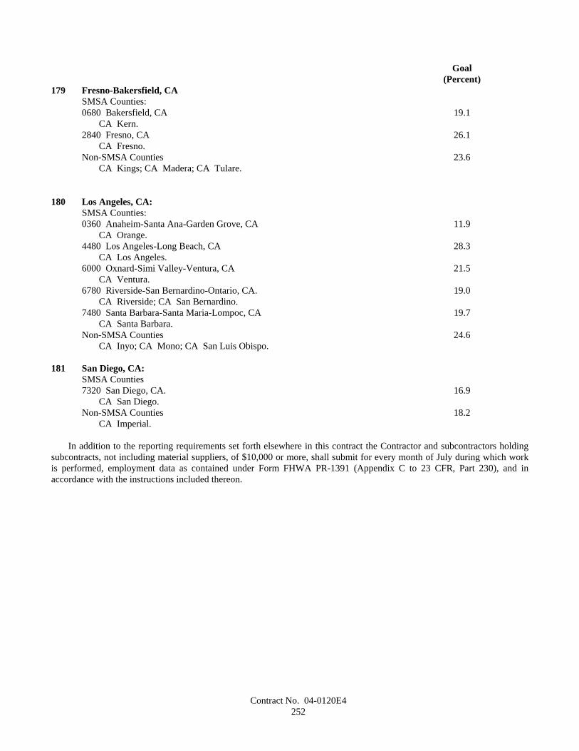
Contract No. 04-0120E4252
Goal(Percent)
179 Fresno-Bakersfield, CASMSA Counties:0680 Bakersfield, CA 19.1
CA Kern.2840 Fresno, CA 26.1
CA Fresno.Non-SMSA Counties 23.6
CA Kings; CA Madera; CA Tulare.
180 Los Angeles, CA:SMSA Counties:0360 Anaheim-Santa Ana-Garden Grove, CA 11.9
CA Orange.4480 Los Angeles-Long Beach, CA 28.3
CA Los Angeles.6000 Oxnard-Simi Valley-Ventura, CA 21.5
CA Ventura.6780 Riverside-San Bernardino-Ontario, CA. 19.0
CA Riverside; CA San Bernardino.7480 Santa Barbara-Santa Maria-Lompoc, CA 19.7
CA Santa Barbara.Non-SMSA Counties 24.6
CA Inyo; CA Mono; CA San Luis Obispo.
181 San Diego, CA:SMSA Counties7320 San Diego, CA. 16.9
CA San Diego.Non-SMSA Counties 18.2
CA Imperial.
In addition to the reporting requirements set forth elsewhere in this contract the Contractor and subcontractors holdingsubcontracts, not including material suppliers, of $10,000 or more, shall submit for every month of July during which workis performed, employment data as contained under Form FHWA PR-1391 (Appendix C to 23 CFR, Part 230), and inaccordance with the instructions included thereon.