


Languages
Pages
Legal

1
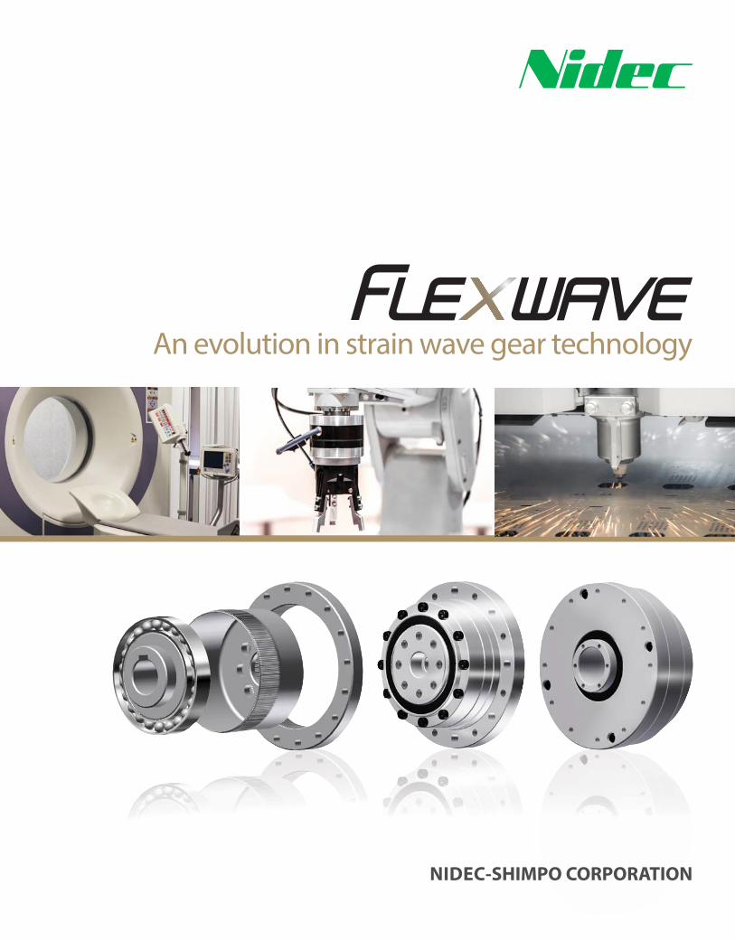
An evolution in strain wave gear technology
NIDEC-SHIMPO CORPORATION

WP SERIES Flexwave
2
Achieving new heights in compact, fi ne precision gear technology
NIDEC-SHIMPO has had a long and storied history supplying the leading robot-
ics and machine tool manufacturers in Japan. Our loyal customers within these
industries strongly urged us to develop our own strain wave gear technology,
and leverage our primary competencies – modularity and fl exibility of the core
design and consistent production in mass volume – to help them become more
competitive in the global marketplace. After extensive eff ort to refi ne strain wave
gear technology and to manufacture at a level that exceeds our customers’ expec-
tations, NIDEC-SHIMPO is proud to introduce our new FLEXWAVE technology.
The NIDEC-SHIMPO FLEXWAVE is a very compact reduction mechanism that
achieves zero backlash, as well as exceptional accuracy and repeatability. The
FLEXWAVE consists of three major internal elements – the elliptical wave gen-
erator subassembly, the fl exible cup gear, and the inner ring gear. The elasticity
properties of the cup gear and the teeth diff erential between the cup gear and the
inner ring gear result in the unique reduction characteristics. When compared to
other reduction technologies, the FLEXWAVE off ers the following advantages;
These characteristics enable the FLEXWAVE to be the superior choice when siz-
ing and selecting the proper reduction technology for ROBOTICS, MEDICAL
EQUIPMENT, SEMICONDUCTOR and CIRCUIT MANUFACTURING, MACHINE
TOOLS or any ASSEMBLY AUTOMATION applications requiring fi ne positioning.
› Near Zero backlash
› High efficiency ratings
› High reduction ratios in a compact footprint
› Exceptional repeatability and torsional stiffness
› Extremely light weight with superior torque density
1
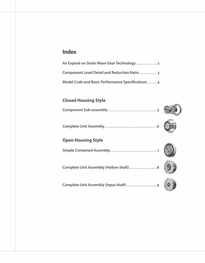
An Exposé on Strain Wave Gear Technology .......................... 2
Component Level Detail and Reduction Ratio ...................... 3
Model Code and Basic Performance Specifi cations ............ 4
Component Sub-assembly ..............................................................5
Open Housing Style
Index
Closed Housing Style
Complete Unit Assembly ..................................................................6
Simple Contained Assembly ...........................................................7
Complete Unit Assembly (Hollow shaft) ...................................8
Complete Unit Assembly (Input shaft) ......................................9
WP SERIES Flexwave
2
An Exposé on Strain Wave Gear Technology
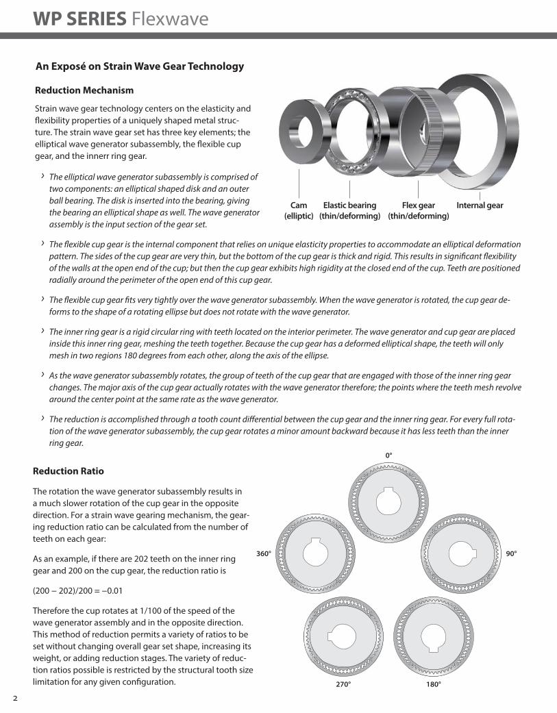
› The elliptical wave generator subassembly is comprised of
two components: an elliptical shaped disk and an outer
ball bearing. The disk is inserted into the bearing, giving
the bearing an elliptical shape as well. The wave generator
assembly is the input section of the gear set.
› The fl exible cup gear is the internal component that relies on unique elasticity properties to accommodate an elliptical deformation
pattern. The sides of the cup gear are very thin, but the bottom of the cup gear is thick and rigid. This results in signifi cant fl exibility
of the walls at the open end of the cup; but then the cup gear exhibits high rigidity at the closed end of the cup. Teeth are positioned
radially around the perimeter of the open end of this cup gear.
› The fl exible cup gear fi ts very tightly over the wave generator subassembly. When the wave generator is rotated, the cup gear de-
forms to the shape of a rotating ellipse but does not rotate with the wave generator.
› The inner ring gear is a rigid circular ring with teeth located on the interior perimeter. The wave generator and cup gear are placed
inside this inner ring gear, meshing the teeth together. Because the cup gear has a deformed elliptical shape, the teeth will only
mesh in two regions 180 degrees from each other, along the axis of the ellipse.
› As the wave generator subassembly rotates, the group of teeth of the cup gear that are engaged with those of the inner ring gear
changes. The major axis of the cup gear actually rotates with the wave generator therefore; the points where the teeth mesh revolve
around the center point at the same rate as the wave generator.
› The reduction is accomplished through a tooth count diff erential between the cup gear and the inner ring gear. For every full rota-
tion of the wave generator subassembly, the cup gear rotates a minor amount backward because it has less teeth than the inner
ring gear.
Reduction Ratio
The rotation the wave generator subassembly results in
a much slower rotation of the cup gear in the opposite
direction. For a strain wave gearing mechanism, the gear-
ing reduction ratio can be calculated from the number of
teeth on each gear:
As an example, if there are 202 teeth on the inner ring
gear and 200 on the cup gear, the reduction ratio is
(200 − 202)/200 = −0.01
Therefore the cup rotates at 1/100 of the speed of the
wave generator assembly and in the opposite direction.
This method of reduction permits a variety of ratios to be
set without changing overall gear set shape, increasing its
weight, or adding reduction stages. The variety of reduc-
tion ratios possible is restricted by the structural tooth size
limitation for any given confi guration.
Reduction Mechanism
Strain wave gear technology centers on the elasticity and
fl exibility properties of a uniquely shaped metal struc-
ture. The strain wave gear set has three key elements; the
elliptical wave generator subassembly, the fl exible cup
gear, and the innerr ring gear.
Flex gear(thin/deforming)
Elastic bearing(thin/deforming)
Cam(elliptic)
Internal gear
0°
360°
270° 180°
90°
3
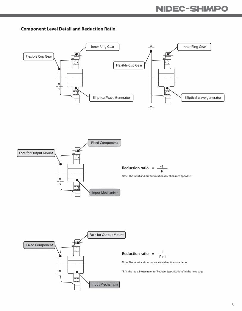
Component Level Detail and Reduction Ratio
-1R
1R+1
Inner Ring Gear
Flexible Cup Gear
Elliptical Wave Generator
Flexible Cup Gear
Inner Ring Gear
Elliptical wave generator
Reduction ratio =
Reduction ratio =
Fixed Component
Fixed Component
Face for Output Mount
Face for Output Mount
Input Mechanism
Note: The input and output rotation directions are opposite
Note: The input and output rotation directions are same
“R” is the ratio. Please refer to “Reducer Specifications” in the next page
Input Mechanism
WP SERIES Flexwave
4
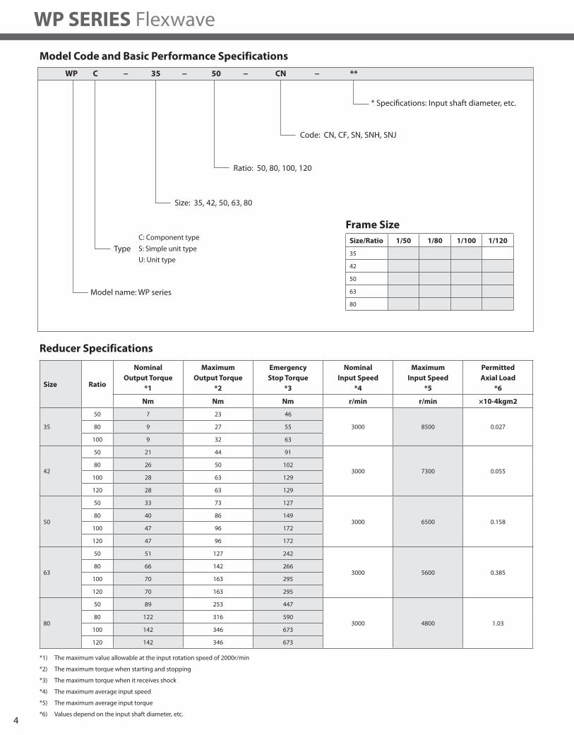
Model Code and Basic Performance Specifications
Reducer Specifications
Code: CN, CF, SN, SNH, SNJ
* Specifications: Input shaft diameter, etc.
Ratio: 50, 80, 100, 120
Size: 35, 42, 50, 63, 80
Model name: WP series
WP −C 35 50 CN **−−−
Type
C: Component type
U: Unit type
S: Simple unit typeSize/Ratio 1/50 1/80 1/100 1/120
35
42
50
63
80
Size Ratio
Nominal
Output Torque
*1
Maximum
Output Torque
*2
Emergency
Stop Torque
*3
Nominal
Input Speed
*4
Maximum
Input Speed
*5
Permitted
Axial Load
*6
Nm Nm Nm r/min r/min ×10-4kgm2
35
50 7 23 46
3000 8500 0.02780 9 27 55
100 9 32 63
42
50 21 44 91
3000 7300 0.05580 26 50 102
100 28 63 129
120 28 63 129
50
50 33 73 127
3000 6500 0.15880 40 86 149
100 47 96 172
120 47 96 172
63
50 51 127 242
3000 5600 0.38580 66 142 266
100 70 163 295
120 70 163 295
80
50 89 253 447
3000 4800 1.0380 122 316 590
100 142 346 673
120 142 346 673
*1) The maximum value allowable at the input rotation speed of 2000r/min
*2) The maximum torque when starting and stopping
*3) The maximum torque when it receives shock
*4) The maximum average input speed
*5) The maximum average input torque
*6) Values depend on the input shaft diameter, etc.
Frame Size
5
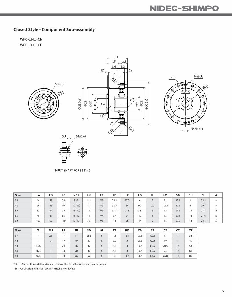
Closed Style - Component Sub-assembly
*1) -CN and -CF are diff erent in dimensions. The -CF value is shown in parentheses
*2) For details in the input section, check the drawings
WPC-□-□-CN
WPC-□-□-CF
Size LA LB LC N *1 LU LT LE LF LG LH LM SG SH SL W
35 44 38 50 8 (6) 3.5 M3 28.5 17.5 6 2 11 15.8 6 18.5 -
42 54 48 60 16 (12) 3.5 M3 32.5 20 6.5 2.5 12.5 15.8 8 20.7 -
50 62 54 70 16 (12) 3.5 M3 33.5 21.5 7.5 3 12 24.8 12 21.5 4
63 75 67 85 16 (12) 4.5 M4 37 24 10 3 13 27.8 14 21.6 5
80 100 90 110 16 (12) 5.5 M5 44 28 14 3 16 27.8 14 23.6 5
Size T SU SA SB SD M ST HD CA CB CX CY CZ
35 - 2.5 17 11 23.5 6 4.5 2.4 C0.5 C0.3 17 1 38
42 - 3 19 10 27 6 5.5 3 C0.5 C0.3 19 1 45
50 13.8 - 24 16 32 8 5.5 3 C0.5 C0.5 20.5 1.5 53
63 16.3 - 30 20 40 8 6.5 3 C0.5 C0.5 23 1.5 66
80 16.3 - 40 26 52 8 8.8 3.2 C0.5 C0.5 26.8 1.5 86
LE
LF
LH LGCY
2-LT
T
W(JS9)
N-ØLU
ØSH (h7)
ØLA
HD
M-ØST
ØSA
CA
SL
C0.5
CA
CB
C0.5C0.5
ØS
B (
H6
)
ØS
G
ØC
Z
ØLC
(h
6)
ØS
D
ØC
Z
SU 2-M3x4
INPUT SHAFT FOR 35 & 42
ØLB
(h
6)
CXR0.4
LM

WP SERIES Flexwave
6
Closed Style - Complete Unit Assembly
*1) -CN and -CF are diff erent in dimensions. The -CF value is shown in parentheses
*2) For details in the input section, check the drawings
WPU-□-□-CN
WPU-□-□-CF
Size LA LB LC LD N *1 LT LU LE LF LG LH LK LM DB SG
35 65 56 73 31 8 (6) M4 4.5 41 27 7 3.5 2 14 38 15.8
42 71 63 79 38 8 (6) M4 4.5 45 29 8 4 2 16 48 15.8
50 82 72 93 45 8 (6) M5 5.5 45.5 28 10 5 3 17.5 56 24.8
63 96 86 107 58 10 (8) M5 5.5 52 36 10 5 3 16 67 27.8
80 125 113 138 78 12 M6 6.5 62 45 12 5 3 17 90 27.8
Size SH SL W T SU SA SB SC M ST HD CX CY CZ
35 6 18.5 - - 2.5 23 11 8 6 M4×8 9.5 1.6 1 38
42 8 20.7 - - 3 27 10 7 6 M5×8 9.5 1.3 1 45
50 12 21.5 4 13.8 - 32 14 10 8 M6×9 9 1.5 1.5 53
63 14 21.6 5 16.3 - 42 20 15 8 M8×10 12 3.4 1.5 66
80 14 23.6 5 16.3 - 55 26 20 8 M10×12 15 5.2 1.5 86
N-LU
N-LT
ØLA
LE
LF
LH LG LK
CY 0-Ring
0-Ring
LM
ØLCC0.5
ØD
B (
h7
)
ØC
Z
ØS
G
SU 2-M3x5
M-ST
ØSA
INPUT SHAFT FOR 35 & 42
SLCX
HD
T
ØSH (h7)
W (JS9)
ØS
C
ØS
B (
h7
)
ØLD
ØLB
(h
7)
7
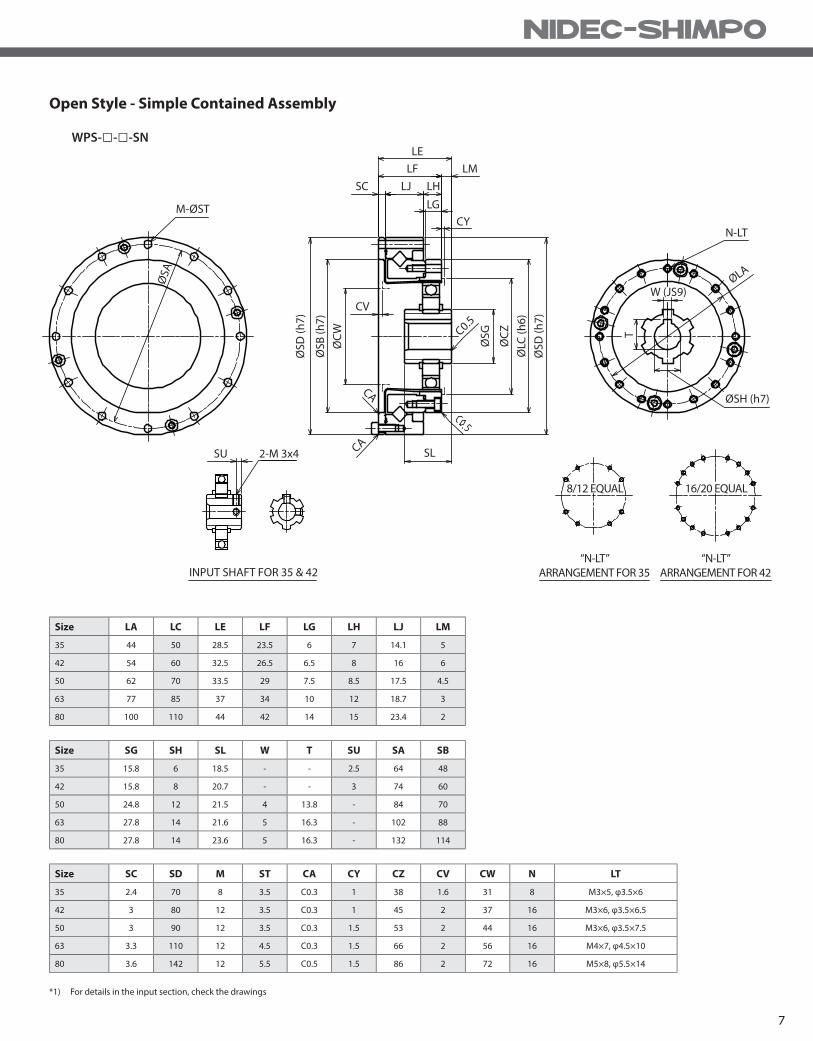
Open Style - Simple Contained Assembly
WPS-□-□-SN
Size SC SD M ST CA CY CZ CV CW N LT
35 2.4 70 8 3.5 C0.3 1 38 1.6 31 8 M3×5, φ3.5×6
42 3 80 12 3.5 C0.3 1 45 2 37 16 M3×6, φ3.5×6.5
50 3 90 12 3.5 C0.3 1.5 53 2 44 16 M3×6, φ3.5×7.5
63 3.3 110 12 4.5 C0.3 1.5 66 2 56 16 M4×7, φ4.5×10
80 3.6 142 12 5.5 C0.5 1.5 86 2 72 16 M5×8, φ5.5×14
Size LA LC LE LF LG LH LJ LM
35 44 50 28.5 23.5 6 7 14.1 5
42 54 60 32.5 26.5 6.5 8 16 6
50 62 70 33.5 29 7.5 8.5 17.5 4.5
63 77 85 37 34 10 12 18.7 3
80 100 110 44 42 14 15 23.4 2
Size SG SH SL W T SU SA SB
35 15.8 6 18.5 - - 2.5 64 48
42 15.8 8 20.7 - - 3 74 60
50 24.8 12 21.5 4 13.8 - 84 70
63 27.8 14 21.6 5 16.3 - 102 88
80 27.8 14 23.6 5 16.3 - 132 114
*1) For details in the input section, check the drawings
N-LT
T
W (JS9)
16/20 EQUAL
“N-LT”
ARRANGEMENT FOR 42
“N-LT”
ARRANGEMENT FOR 35
8/12 EQUAL
ØSH (h7)
ØLA
C0.5
ØS
D (
h7
)
ØLC
(h
6)
ØC
Z
ØS
G
ØS
D (
h7
)
ØS
B (
h7
)
ØC
W
LE
LF LM
SC LJ LH
LG
CY
CV
SLSU 2-M 3x4
INPUT SHAFT FOR 35 & 42
CA
CA
M-ØST
ØSA
WP SERIES Flexwave
8
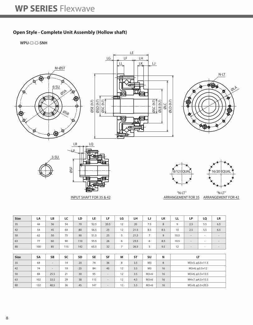
Open Style - Complete Unit Assembly (Hollow shaft)
WPU-□-□-SNH
Size LA LB LC LD LE LF LG LH LJ LK LL LP LQ LR
35 44 36 54 70 52.5 20.5 12 20 7.5 8 9 2.5 5.5 6.5
42 54 45 64 80 56.5 23 12 21.5 8.5 8.5 10 2.5 5.5 6.5
50 62 50 75 90 51.5 25 5 21.5 7 9 10.5 - - -
63 77 60 90 110 55.5 26 6 23.5 6 8.5 10.5 - - -
80 100 85 115 142 65.5 32 7 26.5 5 9.5 12 - - -
Size SA SB SC SD SE SF M ST SU N LT
35 64 - 14 20 74 36 8 3.5 M3 8 M3×5, φ3.5×11.5
42 74 - 19 25 84 45 12 3.5 M3 16 M3×6, φ3.5×12
50 84 25.5 21 30 95 - 12 3.5 M3×6 16 M3×6, φ3.5×13.5
63 102 33.5 29 38 115 - 12 4.5 M3×6 16 M4×7, φ4.5×15.5
80 132 40.5 36 45 147 - 12 5.5 M3×6 16 M5×8, φ5.5×20.5
N-LT
LJLK
LE
LF LHLG
M-ØST
6-SU
ØSA
LL
ØLA
LQLR
ØSB
LP
3-SU
INPUT SHAFT FOR 35 & 42
“N-LT”
ARRANGEMENT FOR 42
16/20 EQUAL8/12 EQUAL
“N-LT”
ARRANGEMENT FOR 35
ØLD
(h
7)
ØLC
ØLB
(h
7)
ØS
C (
h7
)
ØS
E (
h7
)
ØS
D (
h7
)
ØS
C (
h7
)
ØS
F
9
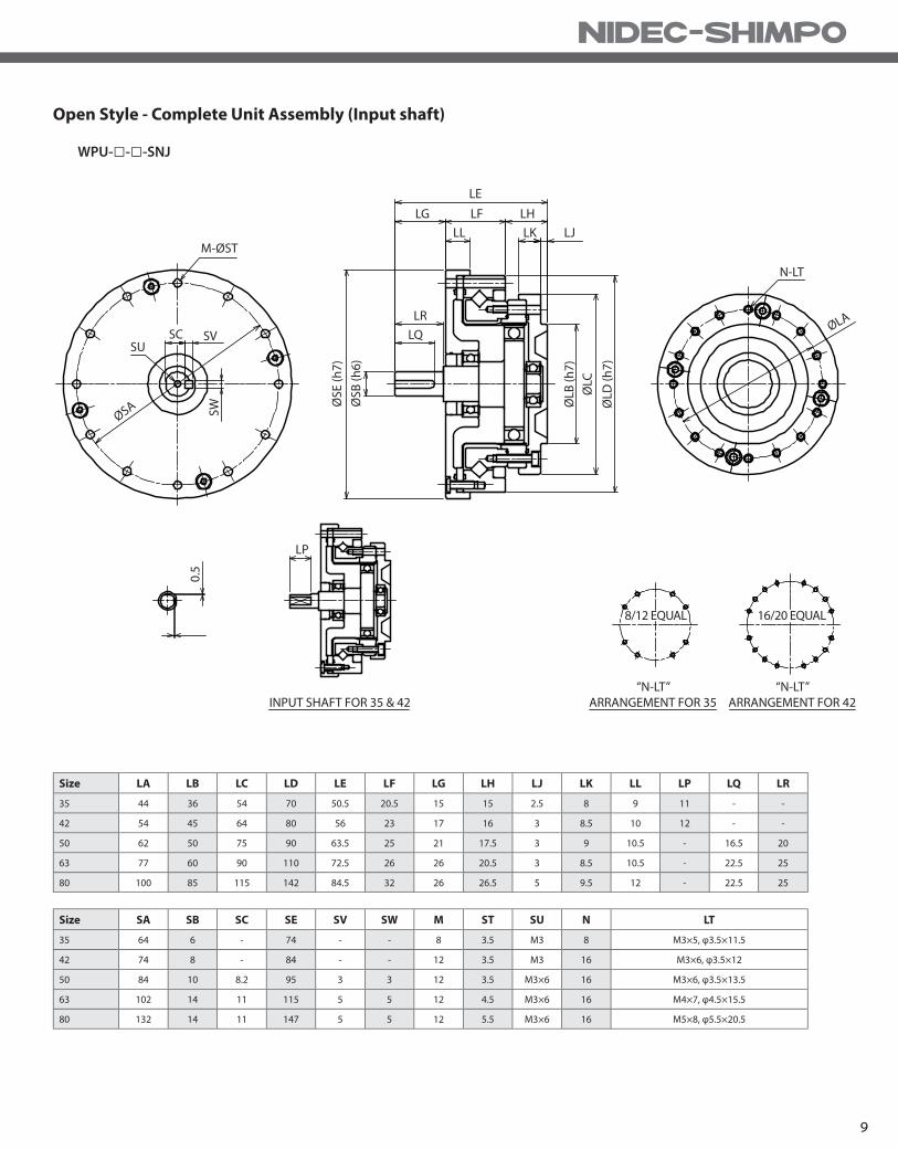
Open Style - Complete Unit Assembly (Input shaft)
WPU-□-□-SNJ
Size LA LB LC LD LE LF LG LH LJ LK LL LP LQ LR
35 44 36 54 70 50.5 20.5 15 15 2.5 8 9 11 - -
42 54 45 64 80 56 23 17 16 3 8.5 10 12 - -
50 62 50 75 90 63.5 25 21 17.5 3 9 10.5 - 16.5 20
63 77 60 90 110 72.5 26 26 20.5 3 8.5 10.5 - 22.5 25
80 100 85 115 142 84.5 32 26 26.5 5 9.5 12 - 22.5 25
Size SA SB SC SE SV SW M ST SU N LT
35 64 6 - 74 - - 8 3.5 M3 8 M3×5, φ3.5×11.5
42 74 8 - 84 - - 12 3.5 M3 16 M3×6, φ3.5×12
50 84 10 8.2 95 3 3 12 3.5 M3×6 16 M3×6, φ3.5×13.5
63 102 14 11 115 5 5 12 4.5 M3×6 16 M4×7, φ4.5×15.5
80 132 14 11 147 5 5 12 5.5 M3×6 16 M5×8, φ5.5×20.5
M-ØST
LE
LF LHLG
LL
LR
LQ
ØS
B (
h6
)
ØS
E (
h7
)
ØLD
(h
7)
ØLC
N-LT
ØLA
ØLB
(h
7)
LK LJ
SU
SW
0.5
LP
INPUT SHAFT FOR 35 & 42
“N-LT”
ARRANGEMENT FOR 35
“N-LT”
ARRANGEMENT FOR 42
16/20 EQUAL8/12 EQUAL
ØSA
SC SV

10
© NIDEC-SHIMPO FLEXWAVE. 12/2016
NIDEC-SHIMPO CORPORATION
1701 Glenlake Avenue, Itasca, IL 60143 USA
Phone: (800) 842-1479 • Fax: (630) 924-7382
www.drives.nidec-shimpo.com
Top Related