


Languages
Pages
Legal


Agility 2018 Hands-on Lab Guide
F5 Solutions for Containers
F5 Networks, Inc.

2
Contents:
1 Getting Started 5
2 Class 1: Introduction to Docker 7
3 Class 2: Introduction to Kubernetes 13
4 Class 3: Introduction to Mesos / Marathon 45
5 Class 4: Introduction to RedHat OpenShift 79
6 Class 5: Advanced Labs for Red Hat OpenShift Container Platform (OCP) 99
3

4
1Getting Started
Important:
• The instructor will provide the necessary details to connect to lab environment.
• Please follow the instructions provided to start your lab and access your jump host.
• All work for this lab will be performed exclusively from the Windows jumpbox via RDP.
• No installation or interaction with your local system is required.
Attention:
• The lab is based on Ravello blueprint Agility 2018-Containers (Exp Nov 9th,2018)-vtog-2.2.2
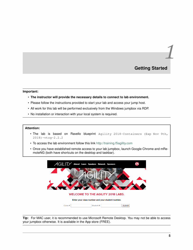
• To access the lab environment follow this link http://training.f5agility.com
• Once you have established remote access to your lab jumpbox, launch Google Chrome and mRe-moteNG (both have shortcuts on the desktop and taskbar).
Tip: For MAC user, it is recommended to use Microsoft Remote Desktop. You may not be able to accessyour jumpbox otherwise. It is available in the App store (FREE).
5

Tip: The default keyboard mapping is set to english. If you need to change it, follow these steps:
1. Click on the start menu button and type ‘language’ in the search field
2. Click on ‘Change keyboards or other input methods’ in the search list
3. Click on ‘Change keyboards. . . ’
4. Click ‘Add. . . ’
5. Select the language you want for your keyboard mapping and click ‘OK’
6. Change the ‘Default input language’ in the drop down list to the language added in the previous step
7. Click ‘Apply’ –> Click ‘OK’ –> Click ‘OK’
6

2Class 1: Introduction to Docker
This introductory class covers the following topics:
2.1 Module 1: Introduction to Docker
2.1.1 Introduction to Docker
Docker and containers have been a growing buzzword in recent years. As companies started asking forintegration with F5, F5 PD resources have been building BIG-IP integration with a BIG-IP controller (morelater in the labs) with a container. Via some configs.yaml files (more later in the labs), you can automate F5into dynamic services being deployed within your organization as well for both on-prem and cloud locations.
To the question what Docker is, and for you reading that haven’t researched what Docker is, Docker is acompany that figured out to simplify some old linux services into an extremely easy and quick way to deploysmaller images than entire guest images as we have been doing for the past 10-15 years on hypervisorsystems.
Let us step back for a moment and look at the context of technologies as they apply to I.T. history.While some products only last moments, others seem to endure forever (COBOL for example – thereare companies still using it today). Some of you reading this will be new to the world of IT, while oth-ers have seen the progression from mainframes, mini, physical servers, Hypervisors, and as of latedocker/containers/microservices, and serverless. Docker is one of companies’ technology that might notbe the end state of IT, but just like COBOL, this docker technology has the power stay around for a verylong time. In much of the same way that VMWare and other hypervisors over the past dozen or so yearshave transformed most businesses physical servers into a world of virtual servers saving cost, floor space,enabling easier management, ability to support snapshots and many other technologies only dreamed ofdecades ago.
In a way, containers are doing what hypervisors did to physical servers. Docker essential developmentdeploying containers via a simplification of old features of Unix (going back to Sun Solaris or FreeBSD fromearly 2000’s with zones and jail to separate users, file system views, and processes). By delivering thisin a container to run specific code i.e. Tomcat, PHP, or WordPress for example. As containers removesthe need to support the Guest OS, this has immediate benefits: running a single file/container with all thesoftware/code embedded within that “image”. Containers are typically much smaller, faster, and easier toswap in/out as needed with code upgrades. A decent laptop can spin up a dozen TomCat Apache serversin about a second with embedded HTML code for your site, or within a few seconds have pulled down newhtml code. Lastly, one can update the container image with new HTML code, save the new container. All
7
while saving over a traditional OS and Tomcat install anywhere from 5X to 25X(or more) less memory anddisk requirements.
For today labs at Agility, all these labs will run in the cloud, due to the number of guests needed tohost a few different management platforms for containers (RedHat Openshift, Kubernetes (K8s), andMesos/Marathon). Next page we will install Docker and run a small container for a “hello world”.
Side note for your own work after today: Windows versus Linux you are in luck (mostly), containers arecross platform or “agnostic” of OS that containers run on. If you decide to install Docker on Linux on yourown (as in next page) you install only the Docker Engine and management tools. You don’t need to createa virtual machine or virtual networks, because Docker via it’s containers will handle the setup for you.
For Windows: having another hypervisor can cause conflicts. During Docker installation, Docker creates aLinux-based virtual machine called MobyLinuxVM. The Docker application connects to this machine, so thatyou can create your container with the necessary apparatus for operation. This installation also configuresa subnet for the virtual machine to communicate with the local network / NAT for your containers to use inthe application. All of these steps occur behind the scenes and, as the user, you don’t really have to worryabout them. Still, the fact that Docker on Windows runs a virtual machine in the background is a majordifference between Docker on Windows and Docker on Linux.
See also:
For more information please come back and visit any of these links below:
https://www.docker.com
https://www.infoworld.com/article/3204171/linux/what-is-docker-linux-containers-explained.html
https://www.zdnet.com/article/what-is-docker-and-why-is-it-so-darn-popular/
Next, we’re going to install Docker and learn some of the basic commands. We’ll do this on a few Ubuntuservers (Kubernetes VM’s in the lab).
Lab 1.1 Install Docker
Important: The following commands need to be run on all three nodes unless otherwise specified.
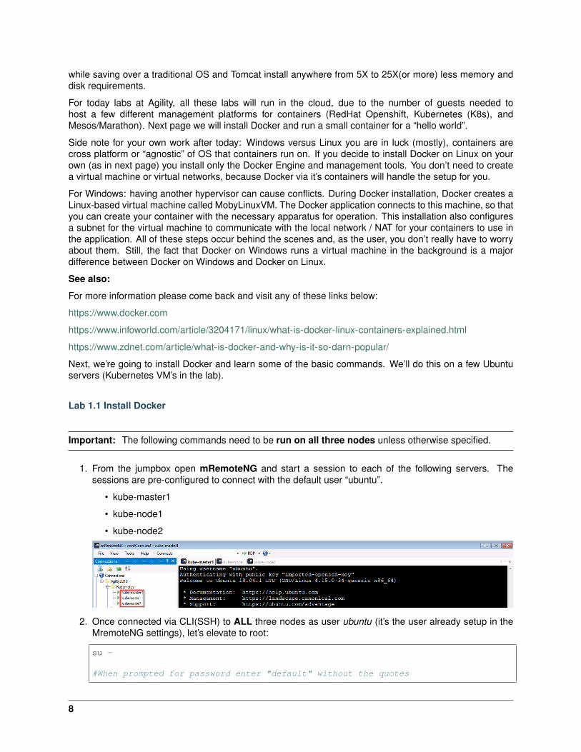
1. From the jumpbox open mRemoteNG and start a session to each of the following servers. Thesessions are pre-configured to connect with the default user “ubuntu”.
• kube-master1
• kube-node1
• kube-node2
2. Once connected via CLI(SSH) to ALL three nodes as user ubuntu (it’s the user already setup in theMremoteNG settings), let’s elevate to root:
su -
#When prompted for password enter "default" without the quotes
8

Your prompt should change to root@ at the start of the line :
3. Then, to ensure the OS is up to date, run the following command
apt update && apt upgrade -y
Note: This can take a few seconds to several minute depending on demand to download the latestupdates for the OS.
4. Add the docker repo
curl \-fsSL https://download.docker.com/linux/ubuntu/gpg | sudo apt-key add \-
add-apt-repository "deb [arch=amd64] https://download.docker.com/linux/ubuntu→˓$(lsb_release -cs) stable"
5. Install the docker packages
apt update && apt install docker-ce -y
6. Verify docker is up and running
docker run --rm hello-world
If everything is working properly you should see the following message
Hint: If you are not a linux/unix person - don’t worry. What happened above is how linux installs andupdates software. This is ALL the ugly (under the cover steps to install apps, and in this case Docker on
9
a Linux host. Please ask questions as to what really happened, but this is how with linux on ubuntu (andmany other linux flavors) installs applications. Linux uses a term called “package manager”, and there aremany: like PIP, YUM, APT, DPKG, RPM, PACMAN, etc. usually one is more favored by the flavor of linux(i.e. debian, ubuntu, redhat, gentoo, OpenSuse, etc.), but at the end of the day they all pretty much do thesame thing, download and keep applications updated.
Lab 1.2 Run a Container on Docker
See also:
This is only a very basic introduction to docker. For everything else see Docker Documentation
1. Continuing from where we left off on the jumpbox go back to the kube-master1 session.
2. Now that docker is up and running and confirmed to be working lets deploy the latest Apache webserver.
Note: The docker run command will first look for a local cache of the container httpd, and uponcomparing that copy to the latest instance, decide to either download an update or use the local copy.Since there is no local copy, docker will download the container httpd to your local cache. This cantake a few seconds (or longer), depending on container size and your bandwidth. Docker will chunkthis into parts called a pull.
--rm “tells docker to remove the container after stopping”
--name “give the container a memorable name”
-d “tells docker to run detached. Without this the container would run in foreground and stop uponexit”
-it “this allows for interactive process, like shell, used together in order to allocate a tty for thecontainer process”
-P “tells docker to auto assign any required ephemeral port and map it to the container”
docker run --rm --name "myapache" -d -it -P httpd:latest
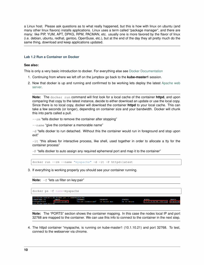
3. If everything is working properly you should see your container running.
Note: -f “lets us filter on key:pair”
docker ps -f name=myapache
Note: The “PORTS” section shows the container mapping. In this case the nodes local IP and port32768 are mapped to the container. We can use this info to connect to the container in the next step.
4. The httpd container “myapache, is running on kube-master1 (10.1.10.21) and port 32768. To test,connect to the webserver via chrome.
10
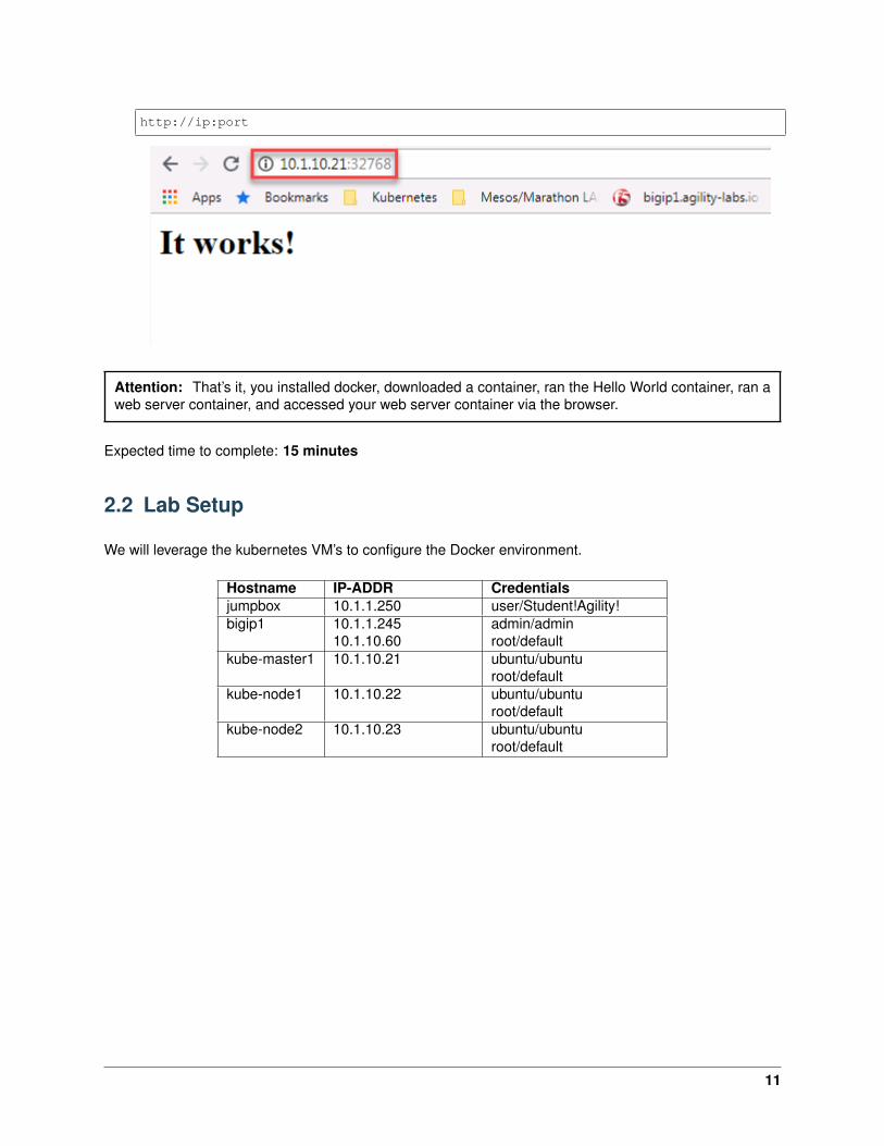
http://ip:port
Attention: That’s it, you installed docker, downloaded a container, ran the Hello World container, ran aweb server container, and accessed your web server container via the browser.
Expected time to complete: 15 minutes
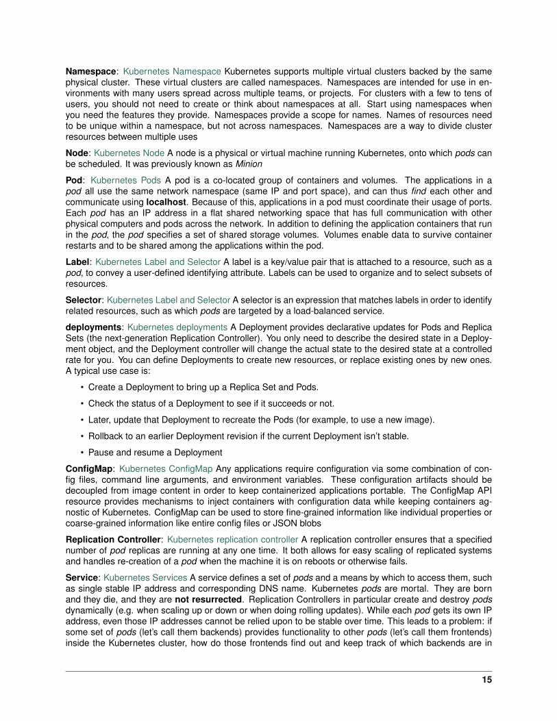
2.2 Lab Setup
We will leverage the kubernetes VM’s to configure the Docker environment.
Hostname IP-ADDR Credentialsjumpbox 10.1.1.250 user/Student!Agility!bigip1 10.1.1.245
10.1.10.60admin/adminroot/default
kube-master1 10.1.10.21 ubuntu/ubunturoot/default
kube-node1 10.1.10.22 ubuntu/ubunturoot/default
kube-node2 10.1.10.23 ubuntu/ubunturoot/default
11

12

3Class 2: Introduction to Kubernetes
This introductory class covers the following topics:
3.1 Module 1: Introduction to Kubernetes
The purpose of this module is to give you a basic understanding of kubernetes concepts and components
3.1.1 Kubernetes Overview
Kubernetes has a lot of documentation available at this location: Kubernetes docs
On this page, we will try to provide all the relevant information to deploy successfully a cluster (Master +nodes)
Overview
Extract from: Kubernetes Cluster Intro
Kubernetes coordinates a highly available cluster of computers that are connected to work as a single unit.The abstractions in Kubernetes allow you to deploy containerized applications to a cluster without tyingthem specifically to individual machines. To make use of this new model of deployment, applications needto be packaged in a way that decouples them from individual hosts: they need to be containerized.
Containerized applications are more flexible and available than in past deployment models, where appli-cations were installed directly onto specific machines as packages deeply integrated into the host. Kuber-netes automates the distribution and scheduling of application containers across a cluster in a more efficientway. Kubernetes is an open-source platform and is production-ready.
A Kubernetes cluster consists of two types of resources:
• The Master coordinates the cluster
• Nodes are the workers that run applications
13

The Master is responsible for managing the cluster. The master coordinates all activity in your cluster,such as scheduling applications, maintaining applications’ desired state, scaling applications, and rollingout new updates.
A node is a VM or a physical computer that serves as a worker machine in a Kubernetes cluster.Each node has a Kubelet, which is an agent for managing the node and communicating with the Kubernetesmaster. The node should also have tools for handling container operations, such as Docker or rkt. Aubernetes cluster that handles production traffic should have a minimum of three nodes.
Masters manage the cluster and the nodes are used to host the running applications.
When you deploy applications on Kubernetes, you tell the master to start the application containers. Themaster schedules the containers to run on the cluster’s nodes. The nodes communicate with the masterusing the Kubernetes API, which the master exposes. End users can also use the Kubernetes API directlyto interact with the cluster.
Kubernetes concepts
Extract from Kubernetes concepts
Cluster: Kubernetes Cluster A cluster is a set of physical or virtual machines and other infrastructureresources used by Kubernetes to run your applications.
14
Namespace: Kubernetes Namespace Kubernetes supports multiple virtual clusters backed by the samephysical cluster. These virtual clusters are called namespaces. Namespaces are intended for use in en-vironments with many users spread across multiple teams, or projects. For clusters with a few to tens ofusers, you should not need to create or think about namespaces at all. Start using namespaces whenyou need the features they provide. Namespaces provide a scope for names. Names of resources needto be unique within a namespace, but not across namespaces. Namespaces are a way to divide clusterresources between multiple uses
Node: Kubernetes Node A node is a physical or virtual machine running Kubernetes, onto which pods canbe scheduled. It was previously known as Minion
Pod: Kubernetes Pods A pod is a co-located group of containers and volumes. The applications in apod all use the same network namespace (same IP and port space), and can thus find each other andcommunicate using localhost. Because of this, applications in a pod must coordinate their usage of ports.Each pod has an IP address in a flat shared networking space that has full communication with otherphysical computers and pods across the network. In addition to defining the application containers that runin the pod, the pod specifies a set of shared storage volumes. Volumes enable data to survive containerrestarts and to be shared among the applications within the pod.
Label: Kubernetes Label and Selector A label is a key/value pair that is attached to a resource, such as apod, to convey a user-defined identifying attribute. Labels can be used to organize and to select subsets ofresources.
Selector: Kubernetes Label and Selector A selector is an expression that matches labels in order to identifyrelated resources, such as which pods are targeted by a load-balanced service.
deployments: Kubernetes deployments A Deployment provides declarative updates for Pods and ReplicaSets (the next-generation Replication Controller). You only need to describe the desired state in a Deploy-ment object, and the Deployment controller will change the actual state to the desired state at a controlledrate for you. You can define Deployments to create new resources, or replace existing ones by new ones.A typical use case is:
• Create a Deployment to bring up a Replica Set and Pods.
• Check the status of a Deployment to see if it succeeds or not.
• Later, update that Deployment to recreate the Pods (for example, to use a new image).
• Rollback to an earlier Deployment revision if the current Deployment isn’t stable.
• Pause and resume a Deployment
ConfigMap: Kubernetes ConfigMap Any applications require configuration via some combination of con-fig files, command line arguments, and environment variables. These configuration artifacts should bedecoupled from image content in order to keep containerized applications portable. The ConfigMap APIresource provides mechanisms to inject containers with configuration data while keeping containers ag-nostic of Kubernetes. ConfigMap can be used to store fine-grained information like individual properties orcoarse-grained information like entire config files or JSON blobs
Replication Controller: Kubernetes replication controller A replication controller ensures that a specifiednumber of pod replicas are running at any one time. It both allows for easy scaling of replicated systemsand handles re-creation of a pod when the machine it is on reboots or otherwise fails.
Service: Kubernetes Services A service defines a set of pods and a means by which to access them, suchas single stable IP address and corresponding DNS name. Kubernetes pods are mortal. They are bornand they die, and they are not resurrected. Replication Controllers in particular create and destroy podsdynamically (e.g. when scaling up or down or when doing rolling updates). While each pod gets its own IPaddress, even those IP addresses cannot be relied upon to be stable over time. This leads to a problem: ifsome set of pods (let’s call them backends) provides functionality to other pods (let’s call them frontends)inside the Kubernetes cluster, how do those frontends find out and keep track of which backends are in
15
that set? Enter Services. A Kubernetes service is an abstraction which defines a logical set of pods and apolicy by which to access them - sometimes called a micro-service. The set of pods targeted by a serviceis (usually) determined by a label selector
Volume: Kuebernetes volume A volume is a directory, possibly with some data in it, which is accessible toa Container as part of its filesystem. Kubernetes volumes build upon Docker Volumes, adding provisioningof the volume directory and/or device.
3.1.2 Kubernetes Networking Overview
This is an extract from Networking in Kubernetes
Summary
Kubernetes assumes that pods can communicate with other pods, regardless of which host they land on.We give every pod its own IP address so you do not need to explicitly create links between pods and youalmost never need to deal with mapping container ports to host ports. This creates a clean, backwards-compatible model where pods can be treated much like VMs or physical hosts from the perspectives of portallocation, naming, service discovery, load balancing, application configuration, and migration
Docker Model
Before discussing the Kubernetes approach to networking, it is worthwhile to review the “normal” way thatnetworking works with Docker.
By default, Docker uses host-private networking. It creates a virtual bridge, called docker0 by default, andallocates a subnet from one of the private address blocks defined in RFC1918 for that bridge. For eachcontainer that Docker creates, it allocates a virtual ethernet device (called veth) which is attached to thebridge. The veth is mapped to appear as eth0 in the container, using Linux namespaces. The in-containereth0 interface is given an IP address from the bridge’s address range. The result is that Docker containerscan talk to other containers only if they are on the same machine (and thus the same virtual bridge).Containers on different machines can not reach each other - in fact they may end up with the exact samenetwork ranges and IP addresses. In order for Docker containers to communicate across nodes, they mustbe allocated ports on the machine’s own IP address, which are then forwarded or proxied to the containers.This obviously means that containers must either coordinate which ports they use very carefully or else beallocated ports dynamically.
Kubernetes Model
Coordinating ports across multiple containers is very difficult to do at scale and exposes users to cluster-level issues outside of their control. Dynamic port allocation brings a lot of complications to the system- every application has to take ports as flags, the API servers have to know how to insert dynamic portnumbers into configuration blocks, services have to know how to find each other, etc. Rather than deal withthis, Kubernetes takes a different approach.
Kubernetes imposes the following fundamental requirements on any networking implementation (barringany intentional network segmentation policies):
• All containers can communicate with all other containers without NAT
• All nodes can communicate with all containers (and vice-versa) without NAT
• The IP that a container sees itself as is the same IP that others see it as
16
• What this means in practice is that you can not just take two computers running Docker and expectKubernetes to work. You must ensure that the fundamental requirements are met.
Kubernetes applies IP addresses at the Pod scope - containers within a Pod share their network names-paces - including their IP address. This means that containers within a Pod can all reach each other’s portson localhost. This does imply that containers within a Pod must coordinate port usage, but this is no dif-ferent than processes in a VM. We call this the IP-per-pod model. This is implemented in Docker as a podcontainer which holds the network namespace open while “app containers” (the things the user specified)join that namespace with Docker’s –net=container:<id> function
How to achieve this
There are a number of ways that this network model can be implemented. Here is a list of possible options:
• Contiv Netplugin
• Flannel
• Open vSwitch
• Calico
• Romana
• Weave Net
• L2 networks and linux bridging
Important: For this lab, we will use Flannel.
3.1.3 Kubernetes Services Overview
Refer to Kubernetes services for more information
A Kubernetes service is an abstraction which defines a logical set of pods and a policy by which to accessthem. The set of pods targeted by a service is (usually) determined by a label selector.
As an example, consider an image-processing backend which is running with 3 replicas. Those replicas arefungible - frontends do not care which backend they use. While the actual pods that compose the backendset may change, the frontend clients should not need to be aware of that or keep track of the list of backendsthemselves. The service abstraction enables this decoupling.
For Kubernetes-native applications, Kubernetes offers a simple Endpoints API that is updated whenever theset of pods in a service changes. For non-native applications, Kubernetes offers a virtual-IP-based bridgeto services* which redirects to the backend pods.
Defining a service
A service in Kubernetes is a REST object, similar to a pod. Like all of the REST objects, a service definitioncan be POSTed to the apiserver to create a new instance. For example, suppose you have a set of podsthat each expose port 9376 and carry a label “app=MyApp”.
1 {2 "kind": "Service",3 "apiVersion": "v1",4 "metadata": {
17
5 "name": "my-service"6 },7 "spec": {8 "selector": {9 "app": "MyApp"
10 },11 "ports": [12 {13 "protocol": "TCP",14 "port": 80,15 "targetPort": 937616 }17 ]18 }19 }
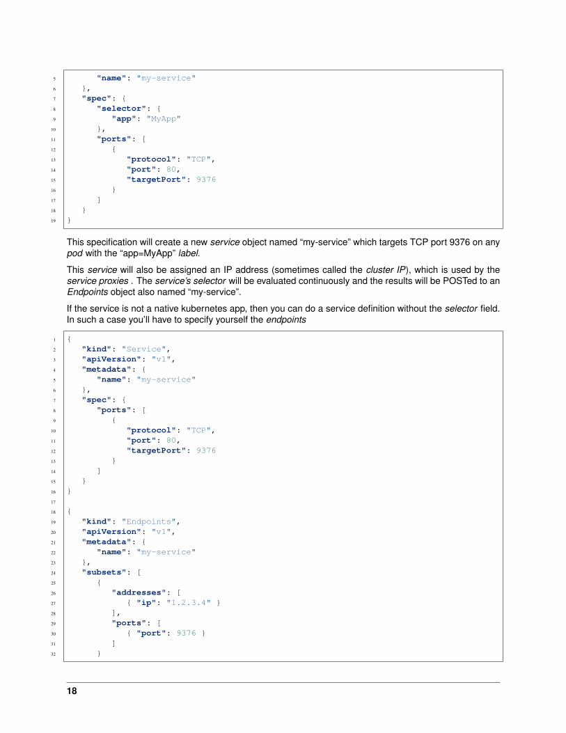
This specification will create a new service object named “my-service” which targets TCP port 9376 on anypod with the “app=MyApp” label.
This service will also be assigned an IP address (sometimes called the cluster IP), which is used by theservice proxies . The service’s selector will be evaluated continuously and the results will be POSTed to anEndpoints object also named “my-service”.
If the service is not a native kubernetes app, then you can do a service definition without the selector field.In such a case you’ll have to specify yourself the endpoints
1 {2 "kind": "Service",3 "apiVersion": "v1",4 "metadata": {5 "name": "my-service"6 },7 "spec": {8 "ports": [9 {
10 "protocol": "TCP",11 "port": 80,12 "targetPort": 937613 }14 ]15 }16 }17
18 {19 "kind": "Endpoints",20 "apiVersion": "v1",21 "metadata": {22 "name": "my-service"23 },24 "subsets": [25 {26 "addresses": [27 { "ip": "1.2.3.4" }28 ],29 "ports": [30 { "port": 9376 }31 ]32 }
18

33 ]34 }
Note: A service can map an incoming port to any targetPort. By default the targetPort will be set to thesame value as the port field. In the example above, the port for the service is 80 (HTTP) and will redirecttraffic to port 9376 on the Pods
You can specify multiple ports if needed (like HTTP/HTTPS for an app)
Kubernetes service supports TCP (default) and UDP.
Publishing services - service types
For some parts of your application (e.g. frontends) you may want to expose a Service onto an external(outside of your cluster, maybe public internet) IP address, other services should be visible only from insideof the cluster.
Kubernetes ServiceTypes allow you to specify what kind of service you want. The default and basetype is *ClusterIP*, which exposes a *service* to connection from inside the cluster. NodePort andLoadBalancer are two types that expose services to external traffic.
Valid values for the ServiceType field are:
• ExternalName: map the service to the contents of the externalName field (e.g. foo.bar.example.com),by returning a CNAME record with its value. No proxying of any kind is set up. This requires version1.7 or higher of kube-dns.
• ClusterIP: use a cluster-internal IP only - this is the default and is discussed above. Choosing thisvalue means that you want this service to be reachable only from inside of the cluster.
• NodePort: on top of having a cluster-internal IP, expose the service on a port on each node of thecluster (the same port on each node). You’ll be able to contact the service on any <NodeIP>:NodePortaddress. If you set the type field to “NodePort”, the Kubernetes master will allocate a port from a flag-configured range (default: 30000-32767), and each Node will proxy that port (the same port numberon every Node) into your Service. That port will be reported in your Service’s spec.ports[*].nodePortfield. If you want a specific port number, you can specify a value in the nodePort field, and the systemwill allocate you that port or else the API transaction will fail (i.e. you need to take care about possibleport collisions yourself). The value you specify must be in the configured range for node ports.
• LoadBalancer: on top of having a cluster-internal IP and exposing service on a NodePort also, askthe cloud provider for a load balancer which forwards to the Service exposed as a <NodeIP>:NodePortfor each Node
Service type: LoadBalancer
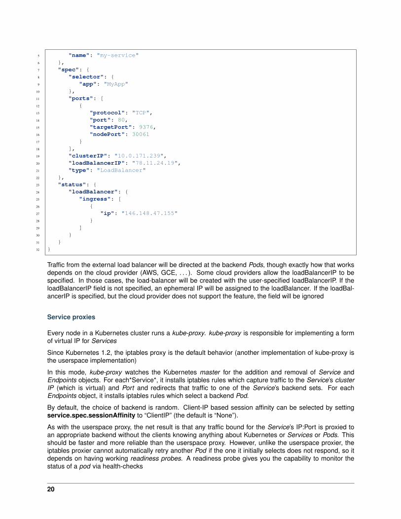
On cloud providers which support external load balancers, setting the type field to “LoadBalancer” will pro-vision a load balancer for your Service. The actual creation of the load balancer happens asynchronously,and information about the provisioned balancer will be published in the Service’s status.loadBalancer field.For example:
1 {2 "kind": "Service",3 "apiVersion": "v1",4 "metadata": {
19
5 "name": "my-service"6 },7 "spec": {8 "selector": {9 "app": "MyApp"
10 },11 "ports": [12 {13 "protocol": "TCP",14 "port": 80,15 "targetPort": 9376,16 "nodePort": 3006117 }18 ],19 "clusterIP": "10.0.171.239",20 "loadBalancerIP": "78.11.24.19",21 "type": "LoadBalancer"22 },23 "status": {24 "loadBalancer": {25 "ingress": [26 {27 "ip": "146.148.47.155"28 }29 ]30 }31 }32 }
Traffic from the external load balancer will be directed at the backend Pods, though exactly how that worksdepends on the cloud provider (AWS, GCE, . . . ). Some cloud providers allow the loadBalancerIP to bespecified. In those cases, the load-balancer will be created with the user-specified loadBalancerIP. If theloadBalancerIP field is not specified, an ephemeral IP will be assigned to the loadBalancer. If the loadBal-ancerIP is specified, but the cloud provider does not support the feature, the field will be ignored
Service proxies
Every node in a Kubernetes cluster runs a kube-proxy. kube-proxy is responsible for implementing a formof virtual IP for Services
Since Kubernetes 1.2, the iptables proxy is the default behavior (another implementation of kube-proxy isthe userspace implementation)
In this mode, kube-proxy watches the Kubernetes master for the addition and removal of Service andEndpoints objects. For each*Service*, it installs iptables rules which capture traffic to the Service’s clusterIP (which is virtual) and Port and redirects that traffic to one of the Service’s backend sets. For eachEndpoints object, it installs iptables rules which select a backend Pod.
By default, the choice of backend is random. Client-IP based session affinity can be selected by settingservice.spec.sessionAffinity to “ClientIP” (the default is “None”).
As with the userspace proxy, the net result is that any traffic bound for the Service’s IP:Port is proxied toan appropriate backend without the clients knowing anything about Kubernetes or Services or Pods. Thisshould be faster and more reliable than the userspace proxy. However, unlike the userspace proxier, theiptables proxier cannot automatically retry another Pod if the one it initially selects does not respond, so itdepends on having working readiness probes. A readiness probe gives you the capability to monitor thestatus of a pod via health-checks
20
Service discovery
The recommended way to implement Service discovery with Kubernetes is the same as with Mesos: DNS
when building a cluster, you can add add-on to it. One of the available add-on is a DNS Server.
The DNS server watches the Kubernetes API for new Services and creates a set of DNS records for each.If DNS has been enabled throughout the cluster then all Pods should be able to do name resolution ofServices automatically.
For example, if you have a Service called “my-service” in Kubernetes Namespace “my-ns” a DNS recordfor “my-service.my-ns” is created. Pods which exist in the “my-ns” Namespace should be able to find it bysimply doing a name lookup for “my-service”. Pods which exist in other Namespaces must qualify the nameas “my-service.my-ns”. The result of these name lookups is the cluster IP.
Kubernetes also supports DNS SRV (service) records for named ports. If the “my-service.my-ns” Servicehas a port named “http” with protocol TCP, you can do a DNS SRV query for “_http._tcp.my-service.my-ns”to discover the port number for “http”
3.2 Module 2: Build a Kubernetes Cluster
In this module, we will build a 3 node cluster (1x master and 2x nodes) utilizing Ubuntu server images.
As a reminder, in this module, our cluster setup is:
Hostname IP-ADDR Rolekube-master1 10.1.10.21 Masterkube-node1 10.1.10.22 Nodekube-node2 10.1.10.23 Node
3.2.1 Lab 2.1 - Prep Ubuntu
Note: This installation will utilize Ubuntu v18.04 (Bionic)
Important: The following commands need to be run on all three nodes unless otherwise specified.
1. From the jumpbox open mRemoteNG and start a session to each of the following servers. Thesessions are pre-configured to connect with the default user “ubuntu”.
• kube-master1
• kube-node1
• kube-node2
Tip: These sessions should be running from the previous Docker lab.
21

2. If not already done from the previous Docker lab elevate to “root”
su -
#When prompted for password enter "default" without the quotes
Your prompt should change to root@ at the start of the line :
3. For your convenience we’ve already added the host IP & names to /etc/hosts. Verify the file
cat /etc/hosts
The file should look like this:
If entries are not there add them to the bottom of the file be editing “/etc/hosts” with ‘vim’
vim /etc/hosts
#cut and paste the following lines to /etc/hosts
10.1.10.21 kube-master110.1.10.22 kube-node110.1.10.23 kube-node2
4. The linux swap file needs to be disabled, this is not the case by default. Again for your conveniencewe disabled swap. Verify the setting
Important: Running a swap file is incompatible with Kubernetes. Lets use the linux top command,which allows users to monitor processes and system resource usage
top
22
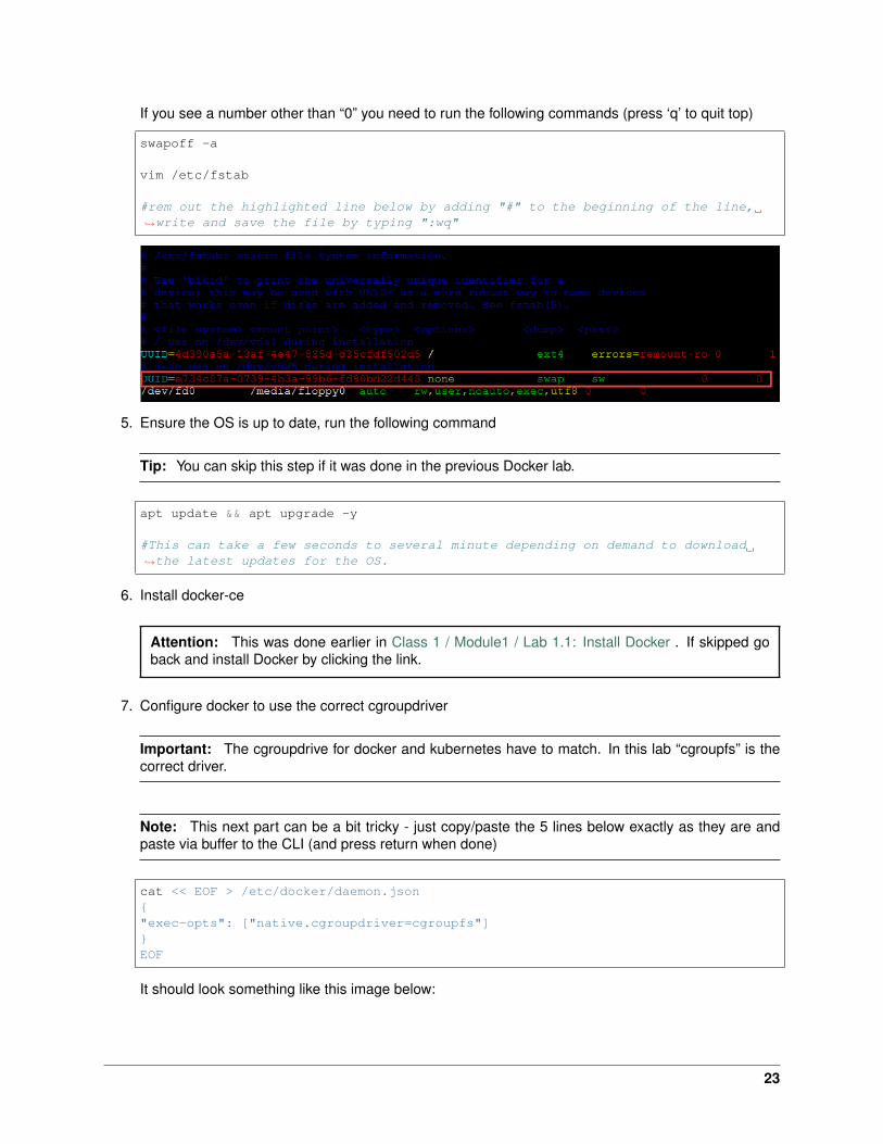
If you see a number other than “0” you need to run the following commands (press ‘q’ to quit top)
swapoff -a
vim /etc/fstab
#rem out the highlighted line below by adding "#" to the beginning of the line,→˓write and save the file by typing ":wq"
5. Ensure the OS is up to date, run the following command
Tip: You can skip this step if it was done in the previous Docker lab.
apt update && apt upgrade -y
#This can take a few seconds to several minute depending on demand to download→˓the latest updates for the OS.
6. Install docker-ce
Attention: This was done earlier in Class 1 / Module1 / Lab 1.1: Install Docker . If skipped goback and install Docker by clicking the link.
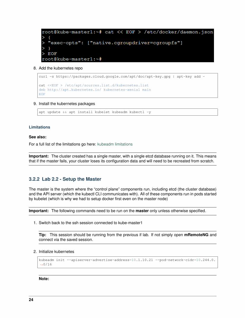
7. Configure docker to use the correct cgroupdriver
Important: The cgroupdrive for docker and kubernetes have to match. In this lab “cgroupfs” is thecorrect driver.
Note: This next part can be a bit tricky - just copy/paste the 5 lines below exactly as they are andpaste via buffer to the CLI (and press return when done)
cat << EOF > /etc/docker/daemon.json{"exec-opts": ["native.cgroupdriver=cgroupfs"]}EOF
It should look something like this image below:
23
8. Add the kubernetes repo
curl -s https://packages.cloud.google.com/apt/doc/apt-key.gpg | apt-key add -
cat <<EOF > /etc/apt/sources.list.d/kubernetes.listdeb http://apt.kubernetes.io/ kubernetes-xenial mainEOF
9. Install the kubernetes packages
apt update && apt install kubelet kubeadm kubectl -y
Limitations
See also:
For a full list of the limitations go here: kubeadm limitations
Important: The cluster created has a single master, with a single etcd database running on it. This meansthat if the master fails, your cluster loses its configuration data and will need to be recreated from scratch.
3.2.2 Lab 2.2 - Setup the Master
The master is the system where the “control plane” components run, including etcd (the cluster database)and the API server (which the kubectl CLI communicates with). All of these components run in pods startedby kubelet (which is why we had to setup docker first even on the master node)
Important: The following commands need to be run on the master only unless otherwise specified.
1. Switch back to the ssh session connected to kube-master1
Tip: This session should be running from the previous if lab. If not simply open mRemoteNG andconnect via the saved session.
2. Initialize kubernetes
kubeadm init --apiserver-advertise-address=10.1.10.21 --pod-network-cidr=10.244.0.→˓0/16
Note:
24
• The IP address used to advertise the master. 10.1.10.0/24 is the network for our control plane. ifyou don’t specify the –apiserver-advertise-address argument, kubeadm will pick the first interfacewith a default gateway (because it needs internet access).
• 10.244.0.0/16 is the default network used by flannel. We’ll setup flannel in a later step.
• Be patient this step takes a few minutes. The initialization is successful if you see “Your Kuber-netes master has initialized successfully!”.
Important:
• Be sure to save the highlighted output from this command to notepad. You’ll need this informationto add your worker nodes and configure user administration.
• The “kubeadm join” command is run on the nodes to register themselves with the master. Keepthe secret safe since anyone with this token can add an authenticated node to your cluster. Thisis used for mutual auth between the master and the nodes.
3. Configure kubernetes administration. At this point you should be logged in as root. The following willupdate both root and ubuntu user accounts for kubernetes administration.
mkdir -p $HOME/.kubesudo cp -i /etc/kubernetes/admin.conf $HOME/.kube/configsudo chown $(id -u):$(id -g) $HOME/.kube/configexitmkdir -p $HOME/.kubesudo cp -i /etc/kubernetes/admin.conf $HOME/.kube/configsudo chown $(id -u):$(id -g) $HOME/.kube/configcd $HOME
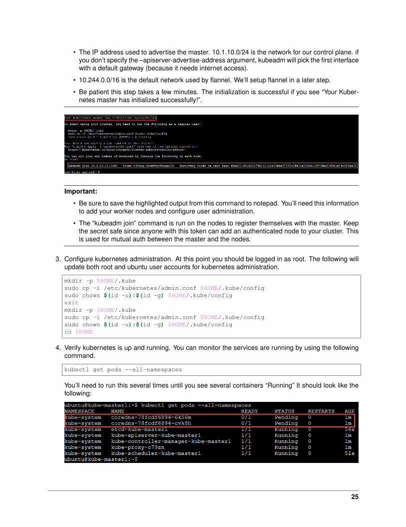
4. Verify kubernetes is up and running. You can monitor the services are running by using the followingcommand.
kubectl get pods --all-namespaces
You’ll need to run this several times until you see several containers “Running” It should look like thefollowing:
25

Note: corends won’t start until the network pod is up and running.
5. Install flannel
kubectl apply -f https://raw.githubusercontent.com/coreos/flannel/master/→˓Documentation/kube-flannel.yml
Note: You must install a pod network add-on so that your pods can communicate with each other.It is necessary to do this before you try to deploy any applications to your cluster, and before“coredns” will start up.
6. If everything installs and starts as expected you should have “coredns” and all services status “Run-ning”. To check the status of core services, you can run the following command:
kubectl get pods --all-namespaces
The output should show all services as running.
Important: Before moving to the next lab, “Setup the Nodes” wait for all system pods to show status“Running”.
7. Additional kubernetes status checks.
kubectl get cs
kubectl cluster-info
Hint: If you made a mistake and need to re-initialize the cluster run the following commands:
26
# If you followed the instructions you should be currently connected as user→˓**ubuntu**# When prompted for password enter "default" without the quotessu -
# This resets the master to default settingskubeadm reset --force
# This removes the admin references to the broken clusterrm -rf /home/ubuntu/.kube /root/.kube
3.2.3 Lab 2.3 - Setup the Nodes
Once the master is setup and running, we need to join our nodes to the cluster.
Important: The following commands need to be run on the worker nodes only unless otherwise specified.
1. To join the master we need to run the command highlighted during the master initialization. You’llneed to use the command saved to notepad in an earlier step.
Warning:
• This following is just an example!! DO not cut/paste the one below. You should have savedthis command after successfully initializing the master in the previous lab. Scroll up in yourCLI history to find the hash your kube-master1 generated to add nodes.
• This command needs to be run on node1 and node2 only!
Hint: If you missed the step to save the “kubeadm join. . . ” command from the previous lab, run thefollowing and use the output to join your nodes to the cluster.
kubeadm token create --print-join-command
kubeadm join 10.1.10.21:6443 --token 12rmdx.z0cbklfaoixhhdfj --discovery-token-ca-→˓cert-hash→˓sha256:c624989e418d92b8040a1609e493c009df5721f4392e90ac6b066c304cebe673
The output should be similar to this:
27
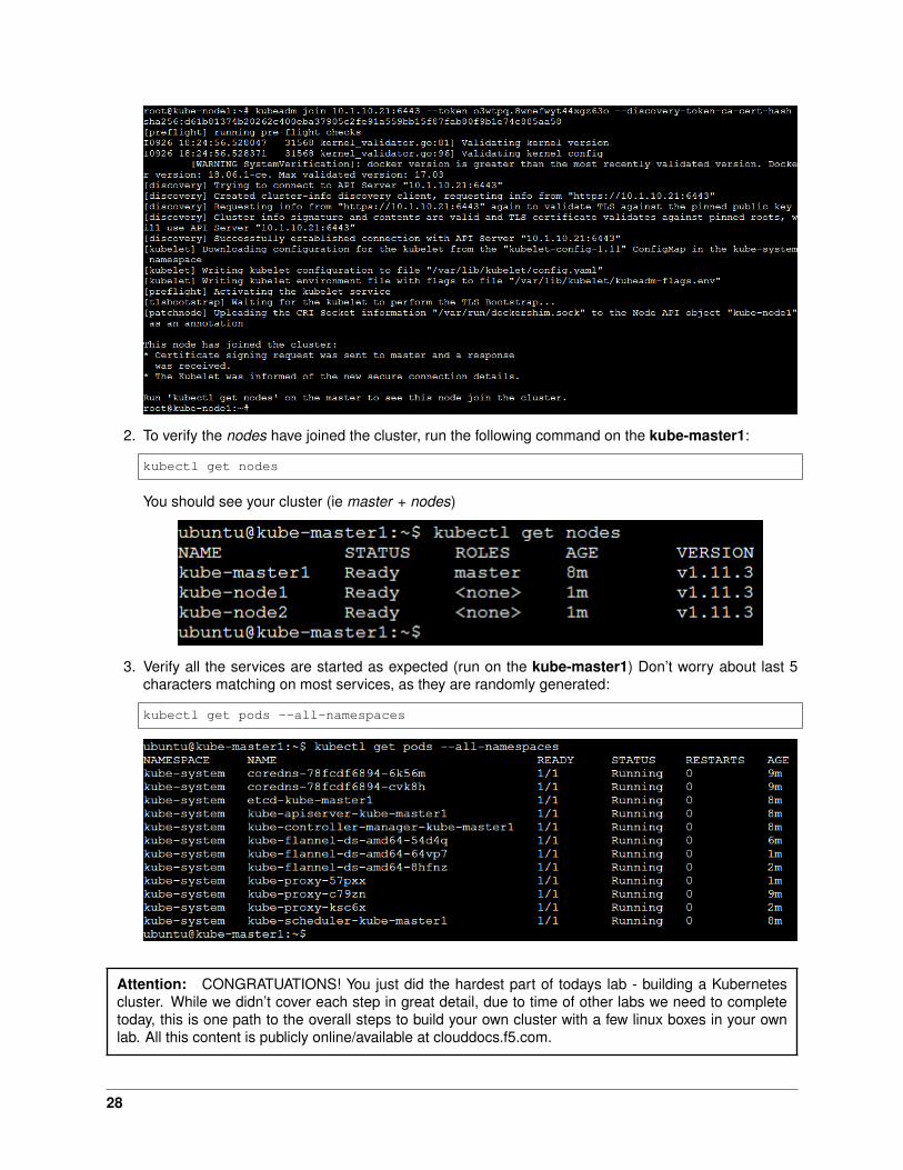
2. To verify the nodes have joined the cluster, run the following command on the kube-master1:
kubectl get nodes
You should see your cluster (ie master + nodes)
3. Verify all the services are started as expected (run on the kube-master1) Don’t worry about last 5characters matching on most services, as they are randomly generated:
kubectl get pods --all-namespaces
Attention: CONGRATUATIONS! You just did the hardest part of todays lab - building a Kubernetescluster. While we didn’t cover each step in great detail, due to time of other labs we need to completetoday, this is one path to the overall steps to build your own cluster with a few linux boxes in your ownlab. All this content is publicly online/available at clouddocs.f5.com.
28
3.2.4 Lab 2.4 - Setup the Kubernetes UI
Important: The following commands need to be run on the master only.
Note: You have two options to install the UI:
1. Run the included script from the cloned git repo.
2. Manually run each command.
Both options are included below.
1. “git” the demo files
Note: These files should be here by default, if NOT run the following commands.
git clone https://github.com/f5devcentral/f5-agility-labs-containers.git ~/→˓agilitydocs
cd ~/agilitydocs/kubernetes
2. Run the following commands to configure the UI
Note: A script is included in the cloned git repo from the previous step. In the interest of time youcan simply use the script.
cd /home/ubuntu/agilitydocs/kubernetes
./create-kube-dashboard
or run through the following steps:
kubectl create serviceaccount kubernetes-dashboard -n kube-system
kubectl create clusterrolebinding kubernetes-dashboard --clusterrole=cluster-→˓admin --serviceaccount=kube-system:kubernetes-dashboard
Warning: These commands create a service account with full admin rights. In a typical deploy-ment this would be overkill.
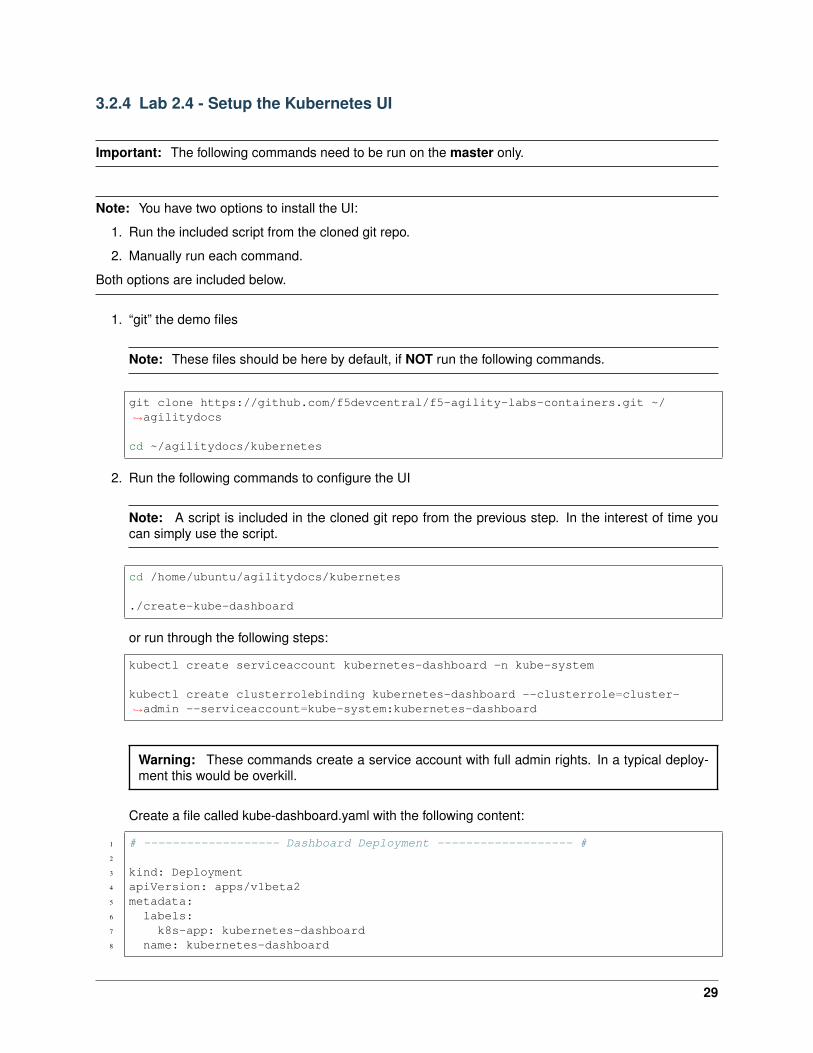
Create a file called kube-dashboard.yaml with the following content:
1 # ------------------- Dashboard Deployment ------------------- #2
3 kind: Deployment4 apiVersion: apps/v1beta25 metadata:6 labels:7 k8s-app: kubernetes-dashboard8 name: kubernetes-dashboard
29
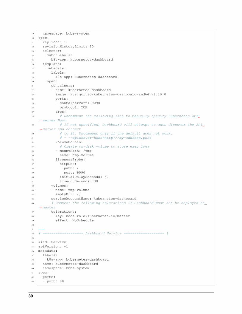
9 namespace: kube-system10 spec:11 replicas: 112 revisionHistoryLimit: 1013 selector:14 matchLabels:15 k8s-app: kubernetes-dashboard16 template:17 metadata:18 labels:19 k8s-app: kubernetes-dashboard20 spec:21 containers:22 - name: kubernetes-dashboard23 image: k8s.gcr.io/kubernetes-dashboard-amd64:v1.10.024 ports:25 - containerPort: 909026 protocol: TCP27 args:28 # Uncomment the following line to manually specify Kubernetes API
→˓server Host29 # If not specified, Dashboard will attempt to auto discover the API
→˓server and connect30 # to it. Uncomment only if the default does not work.31 # - --apiserver-host=http://my-address:port32 volumeMounts:33 # Create on-disk volume to store exec logs34 - mountPath: /tmp35 name: tmp-volume36 livenessProbe:37 httpGet:38 path: /39 port: 909040 initialDelaySeconds: 3041 timeoutSeconds: 3042 volumes:43 - name: tmp-volume44 emptyDir: {}45 serviceAccountName: kubernetes-dashboard46 # Comment the following tolerations if Dashboard must not be deployed on
→˓master47 tolerations:48 - key: node-role.kubernetes.io/master49 effect: NoSchedule50
51 ---52 # ------------------- Dashboard Service ------------------- #53
54 kind: Service55 apiVersion: v156 metadata:57 labels:58 k8s-app: kubernetes-dashboard59 name: kubernetes-dashboard60 namespace: kube-system61 spec:62 ports:63 - port: 80
30

64 targetPort: 909065 type: NodePort66 selector:67 k8s-app: kubernetes-dashboard
Apply Kubernetes manifest file:
kubectl apply -f kube-dashboard.yaml
3. To access the dashboard, you need to see which port it is listening on. You can find this informationwith the following command:
kubectl describe svc kubernetes-dashboard -n kube-system
Note: In our service we are assigned port “30156” (NodePort), you’ll be assigned a different port.
We can now access the dashboard by connecting to the following uri http://10.1.10.21:30156
31
3.3 Module 3: F5 Container Connector with Kubernetes
3.3.1 Overview
The Container Connector makes L4-L7 services available to users deploying microservices-based applica-tions in a containerized infrastructure. The CC - Kubernetes allows you to expose a Kubernetes Serviceoutside the cluster as a virtual server on a BIG-IP® device entirely through the Kubernetes API.
See also:
The official F5 documentation is here: F5 Container Connector - Kubernetes
3.3.2 Architecture
The Container Connector for Kubernetes comprises the f5-k8s-controller and user-defined “F5 resources”.The f5-k8s-controller is a Docker container that can run in a Kubernetes Pod. The “F5 resources” areKubernetes ConfigMap resources that pass encoded data to the f5-k8s-controller. These resources tell thef5-k8s-controller:
• What objects to configure on your BIG-IP.
• What Kubernetes Service the BIG-IP objects belong to (the frontend and backend properties in theConfigMap, respectively).
The f5-k8s-controller watches for the creation and modification of F5 resources in Kubernetes. When itdiscovers changes, it modifies the BIG-IP accordingly. For example, for an F5 virtualServer resource, theCC - Kubernetes does the following:
• Creates objects to represent the virtual server on the BIG-IP in the specified partition.
• Creates pool members for each node in the Kubernetes cluster, using the NodePort assigned to theservice port by Kubernetes.
• Monitors the F5 resources and linked Kubernetes resources for changes and reconfigures the BIG-IPaccordingly.
• The BIG-IP then handles traffic for the Service on the specified virtual address and load-balances toall nodes in the cluster.
• Within the cluster, the allocated NodePort is load-balanced to all pods for the Service.
3.3.3 Prerequisites
Before being able to use the F5 Container Connector, you need to confirm the following:
• You must have a fully active/licensed BIG-IP
• A BIG-IP partition needs to be setup for the Container Connector.
• You need a user with administrative access to this partition
• Your kubernetes environment must be up and running already
Lab 3.1 - F5 Container Connector Setup
The BIG-IP Controller for Kubernetes installs as a Deployment object
See also:
32
The official CC documentation is here: Install the BIG-IP Controller: Kubernetes
BIG-IP Setup
To use F5 Container connector, you’ll need a BIG-IP up and running first.
Through the Jumpbox, you should have a BIG-IP available at the following URL: https://10.1.1.245
Warning: Connect to your BIG-IP and check it is active and licensed. Its login and password are:admin/admin
If your BIG-IP has no license or its license expired, renew the license. You just need a LTM VE licensefor this lab. No specific add-ons are required (ask a lab instructor for eval licenses if your license hasexpired)
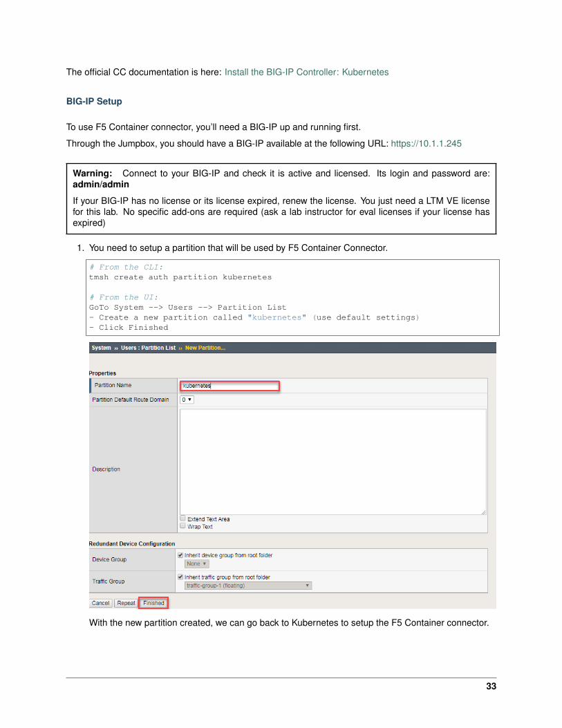
1. You need to setup a partition that will be used by F5 Container Connector.
# From the CLI:tmsh create auth partition kubernetes
# From the UI:GoTo System --> Users --> Partition List- Create a new partition called "kubernetes" (use default settings)- Click Finished
With the new partition created, we can go back to Kubernetes to setup the F5 Container connector.
33

Container Connector Deployment
See also:
For a more thorough explanation of all the settings and options see F5 Container Connector - Kubernetes
Now that BIG-IP is licensed and prepped with the “kubernetes” partition, we need to define a Kubernetesdeployment and create a Kubernetes secret to hide our bigip credentials.
1. From the jumpbox open mRemoteNG and start a session with Kube-master.
Tip:
• These sessions should be running from the previous lab.
• As a reminder we’re utilizing a wrapper called MRemoteNG for Putty and other services. MRNGhold credentials and allows for multiple protocols(i.e. SSH, RDP, etc.), makes jumping in and outof SSH connections easier.
On your desktop select MRemoteNG, once launched you’ll see a few tabs similar to the examplebelow. Open up the Kubernetes / Kubernetes-Cluster folder and double click kube-master1.
2. “git” the demo files
Note: These files should be here by default, if NOT run the following commands.
git clone https://github.com/f5devcentral/f5-agility-labs-containers.git ~/→˓agilitydocs
cd ~/agilitydocs/kubernetes
34

3. Create bigip login secret
kubectl create secret generic bigip-login -n kube-system --from-→˓literal=username=admin --from-literal=password=admin
You should see something similar to this:
4. Create kubernetes service account for bigip controller
kubectl create serviceaccount k8s-bigip-ctlr -n kube-system
You should see something similar to this:
5. Create cluster role for bigip service account (admin rights, but can be modified for your environment)
kubectl create clusterrolebinding k8s-bigip-ctlr-clusteradmin --→˓clusterrole=cluster-admin --serviceaccount=kube-system:k8s-bigip-ctlr
You should see something similar to this:
6. At this point we have two deployment mode options, Nodeport or Cluster. For more information seeBIG-IP Controller Modes
Important: This lab will focus on Nodeport. In Class 4 Openshift we’ll use ClusterIP.
7. Nodeport mode f5-nodeport-deployment.yaml
Note:
• For your convenience the file can be found in /home/ubuntu/agilitydocs/kubernetes (downloadedearlier in the clone git repo step).
• Or you can cut and paste the file below and create your own file.
• If you have issues with your yaml and syntax (indentation MATTERS), you can try to use anonline parser to help you : Yaml parser
1 apiVersion: extensions/v1beta12 kind: Deployment3 metadata:4 name: k8s-bigip-ctlr-deployment5 namespace: kube-system6 spec:7 replicas: 18 template:9 metadata:
10 name: k8s-bigip-ctlr
35

11 labels:12 app: k8s-bigip-ctlr13 spec:14 serviceAccountName: k8s-bigip-ctlr15 containers:16 - name: k8s-bigip-ctlr17 image: "f5networks/k8s-bigip-ctlr:latest"18 imagePullPolicy: IfNotPresent19 env:20 - name: BIGIP_USERNAME21 valueFrom:22 secretKeyRef:23 name: bigip-login24 key: username25 - name: BIGIP_PASSWORD26 valueFrom:27 secretKeyRef:28 name: bigip-login29 key: password30 command: ["/app/bin/k8s-bigip-ctlr"]31 args: [32 "--bigip-username=$(BIGIP_USERNAME)",33 "--bigip-password=$(BIGIP_PASSWORD)",34 "--bigip-url=10.1.10.60",35 "--bigip-partition=kubernetes",36 "--namespace=default",37 "--pool-member-type=nodeport"38 ]
8. Once you have your yaml file setup, you can try to launch your deployment. It will start our f5-k8s-controller container on one of our nodes (may take around 30sec to be in a running state):
kubectl create -f f5-nodeport-deployment.yaml
9. Verify the deployment “deployed”
kubectl get deployment k8s-bigip-ctlr-deployment --namespace kube-system
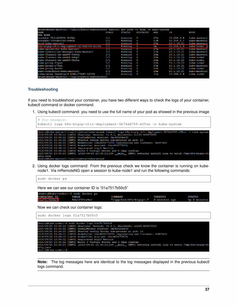
10. To locate on which node the container connector is running, you can use the following command:
kubectl get pods -o wide -n kube-system
We can see that our container is running on kube-node2 below.
36
Troubleshooting
If you need to troubleshoot your container, you have two different ways to check the logs of your container,kubectl command or docker command.
1. Using kubectl command: you need to use the full name of your pod as showed in the previous image
# For example:kubectl logs k8s-bigip-ctlr-deployment-5b74dd769-x55vx -n kube-system
2. Using docker logs command: From the previous check we know the container is running on kube-node1. Via mRemoteNG open a session to kube-node1 and run the following commands:
sudo docker ps
Here we can see our container ID is “01a7517b50c5”
Now we can check our container logs:
sudo docker logs 01a7517b50c5
Note: The log messages here are identical to the log messages displayed in the previous kubectllogs command.
37

3. You can connect to your container with kubectl as well:
kubectl exec -it k8s-bigip-ctlr-deployment-79fcf97bcc-48qs7 -n kube-system -- /→˓bin/sh
cd /app
ls -la
exit
Lab 3.2 - F5 Container Connector Usage
Now that our container connector is up and running, let’s deploy an application and leverage our F5 CC.
For this lab we’ll use a simple pre-configured docker image called “f5-hello-world”. It can be found on dockerhub at f5devcentral/f5-hello-world
To deploy our application, we will need to do the following:
1. Define a Deployment: this will launch our application running in a container.
2. Define a ConfigMap: this can be used to store fine-grained information like individual properties orcoarse-grained information like entire config files or JSON blobs. It will contain the BIG-IP configura-tion we need to push.
3. Define a Service: this is an abstraction which defines a logical set of pods and a policy by whichto access them. Expose the service on a port on each node of the cluster (the same port on eachnode). You’ll be able to contact the service on any <NodeIP>:NodePort address. If you set the typefield to “NodePort”, the Kubernetes master will allocate a port from a flag-configured range (default:30000-32767), and each Node will proxy that port (the same port number on every Node) into yourService.
App Deployment
On kube-master1 we will create all the required files:
1. Create a file called f5-hello-world-deployment.yaml
Tip: Use the file in /home/ubuntu/agilitydocs/kubernetes
1 apiVersion: extensions/v1beta12 kind: Deployment3 metadata:4 name: f5-hello-world5 spec:6 replicas: 27 template:8 metadata:9 labels:
10 run: f5-hello-world11 spec:12 containers:13 - name: f5-hello-world14 image: "f5devcentral/f5-hello-world:latest"
38
15 imagePullPolicy: IfNotPresent16 ports:17 - containerPort: 808018 protocol: TCP
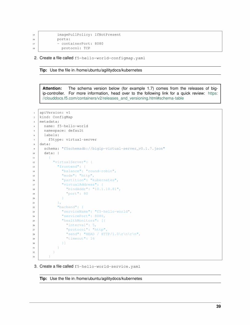
2. Create a file called f5-hello-world-configmap.yaml
Tip: Use the file in /home/ubuntu/agilitydocs/kubernetes
Attention: The schema version below (for example 1.7) comes from the releases of big-ip-controller. For more information, head over to the following link for a quick review: https://clouddocs.f5.com/containers/v2/releases_and_versioning.html#schema-table
1 apiVersion: v12 kind: ConfigMap3 metadata:4 name: f5-hello-world5 namespace: default6 labels:7 f5type: virtual-server8 data:9 schema: "f5schemadb://bigip-virtual-server_v0.1.7.json"
10 data: |11 {12 "virtualServer": {13 "frontend": {14 "balance": "round-robin",15 "mode": "http",16 "partition": "kubernetes",17 "virtualAddress": {18 "bindAddr": "10.1.10.81",19 "port": 8020 }21 },22 "backend": {23 "serviceName": "f5-hello-world",24 "servicePort": 8080,25 "healthMonitors": [{26 "interval": 5,27 "protocol": "http",28 "send": "HEAD / HTTP/1.0\r\n\r\n",29 "timeout": 1630 }]31 }32 }33 }
3. Create a file called f5-hello-world-service.yaml
Tip: Use the file in /home/ubuntu/agilitydocs/kubernetes
39

1 apiVersion: v12 kind: Service3 metadata:4 name: f5-hello-world5 labels:6 run: f5-hello-world7 spec:8 ports:9 - port: 8080
10 protocol: TCP11 targetPort: 808012 type: NodePort13 selector:14 run: f5-hello-world
4. We can now launch our application:
kubectl create -f f5-hello-world-deployment.yamlkubectl create -f f5-hello-world-configmap.yamlkubectl create -f f5-hello-world-service.yaml
5. To check the status of our deployment, you can run the following commands:
kubectl get pods -o wide
# This can take a few seconds to a minute to create these hello-world containers→˓to running state.
kubectl describe svc f5-hello-world
6. To test the app you need to pay attention to:
40

The NodePort value, that’s the port used by Kubernetes to give you access to the app from theoutside. Here it’s “30507”, highlighted above.
The Endpoints, that’s our 2 instances (defined as replicas in our deployment file) and the port as-signed to the service: port 8080.
Now that we have deployed our application sucessfully, we can check our BIG-IP configuration. Fromthe browser open https://10.1.1.245
Warning: Don’t forget to select the “kubernetes” partition or you’ll see nothing.
Here you can see a new Virtual Server, “default_f5-hello-world” was created, listening on 10.1.10.81.
Check the Pools to see a new pool and the associated pool members: Local Traffic –> Pools –>“cfgmap_default_f5-hello-world_f5-hello-world” –> Members
41

Note: You can see that the pool members listed are all the kubernetes nodes. (NodePort mode)
7. Now you can try to access your application via your BIG-IP VIP: 10.1.10.81
8. Hit Refresh many times and go back to your BIG-IP UI, go to Local Traffic –> Pools –> Pool list –>cfgmap_default_f5-hello-world_f5-hello-world –> Statistics to see that traffic is distributed as expected.
9. How is traffic forwarded in Kubernetes from the <node IP>:30507 to the <container IP>:8080? This isdone via iptables that is managed via the kube-proxy instances. On either of the nodes, SSH in andrun the following command:
sudo iptables-save | grep f5-hello-world
This will list the different iptables rules that were created regarding our service.
42

10. Scale the f5-hello-world app
kubectl scale --replicas=10 deployment/f5-hello-world -n default
11. Check that the pods were created
kubectl get pods
12. Check the pool was updated on big-ip
43
Attention: Why are there only 2 pool members?
Expected time to complete: 1 hours
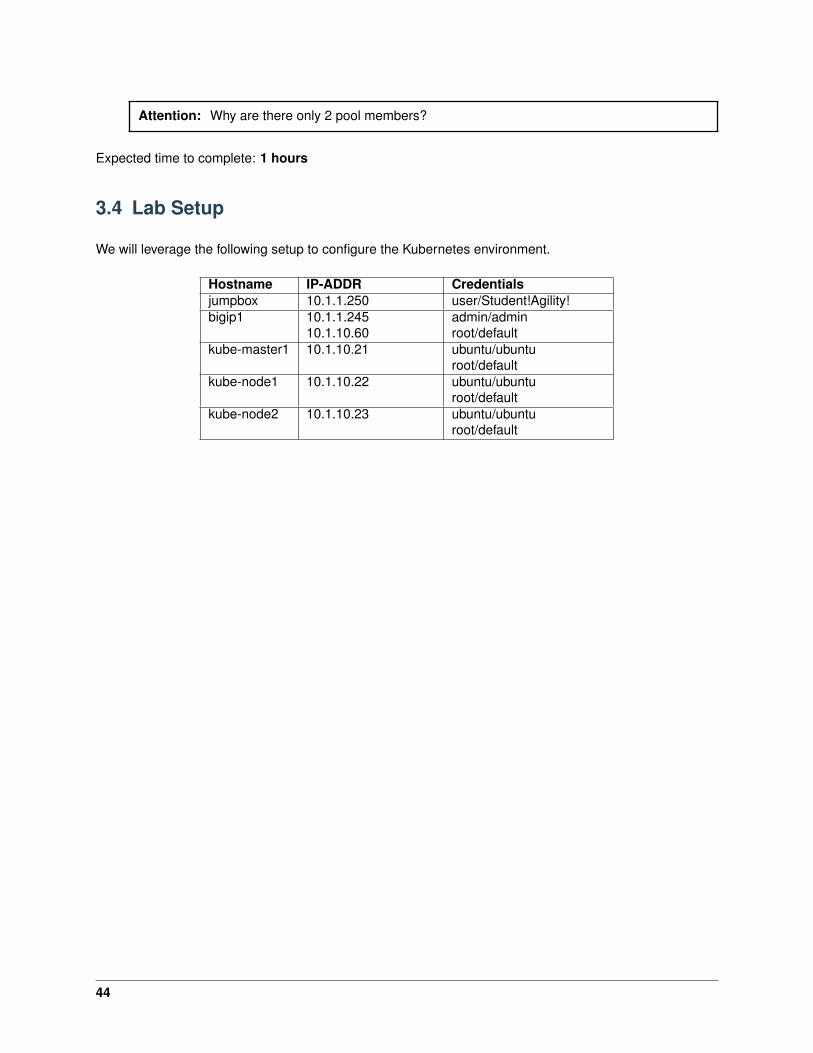
3.4 Lab Setup
We will leverage the following setup to configure the Kubernetes environment.
Hostname IP-ADDR Credentialsjumpbox 10.1.1.250 user/Student!Agility!bigip1 10.1.1.245
10.1.10.60admin/adminroot/default
kube-master1 10.1.10.21 ubuntu/ubunturoot/default
kube-node1 10.1.10.22 ubuntu/ubunturoot/default
kube-node2 10.1.10.23 ubuntu/ubunturoot/default
44
4Class 3: Introduction to Mesos / Marathon
This introductory class covers the following topics:
4.1 Module 1: Introduction to Mesos / Marathon
The purpose of this module is to give you a basic understanding of Mesos / Marathon concepts and com-ponents
4.1.1 Mesos / Marathon Overview
The F5 Marathon Container Integration consists of the F5 Marathon BIG-IP Controller.
The F5 Marathon BIG-IP Controller configures a BIG-IP to expose applications in a Mesos cluster as BIG-IPvirtual servers, serving North-South traffic.
See also:
The official F5 documentation is available here: F5 Marathon Container Integration
You can either setup the whole F5 solutions yourself or use some scripts to automatically deploy everything.
We also provide some ansible playbooks if you need to setup a Mesos/Marathon env.
Before working on the installation itself, you need to understand the different components involved in thissetup:
• Master / Agent functions
• The different components involved in the Master / Agent architecture
• How High availability is achieved
• Marathon overview
Mesos Architecture
This is an extract from Mesos Architecture
45
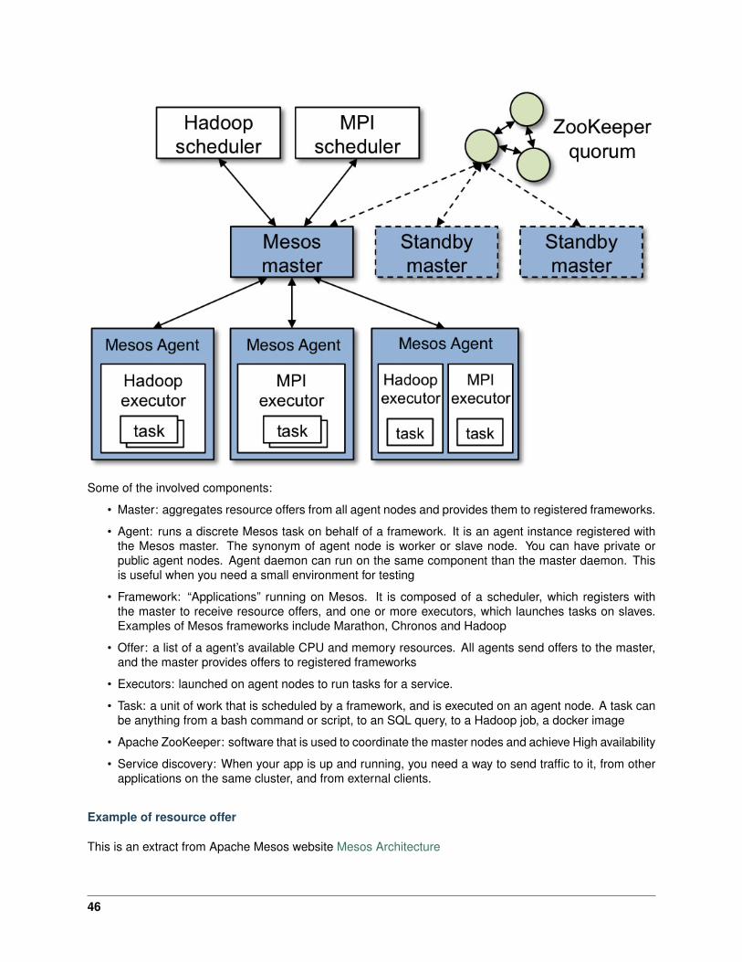
Some of the involved components:
• Master: aggregates resource offers from all agent nodes and provides them to registered frameworks.
• Agent: runs a discrete Mesos task on behalf of a framework. It is an agent instance registered withthe Mesos master. The synonym of agent node is worker or slave node. You can have private orpublic agent nodes. Agent daemon can run on the same component than the master daemon. Thisis useful when you need a small environment for testing
• Framework: “Applications” running on Mesos. It is composed of a scheduler, which registers withthe master to receive resource offers, and one or more executors, which launches tasks on slaves.Examples of Mesos frameworks include Marathon, Chronos and Hadoop
• Offer: a list of a agent’s available CPU and memory resources. All agents send offers to the master,and the master provides offers to registered frameworks
• Executors: launched on agent nodes to run tasks for a service.
• Task: a unit of work that is scheduled by a framework, and is executed on an agent node. A task canbe anything from a bash command or script, to an SQL query, to a Hadoop job, a docker image
• Apache ZooKeeper: software that is used to coordinate the master nodes and achieve High availability
• Service discovery: When your app is up and running, you need a way to send traffic to it, from otherapplications on the same cluster, and from external clients.
Example of resource offer
This is an extract from Apache Mesos website Mesos Architecture
46
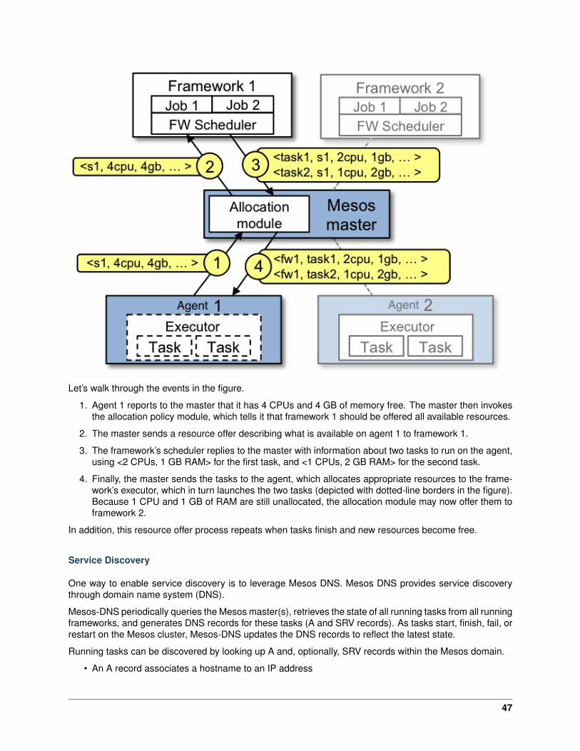
Let’s walk through the events in the figure.
1. Agent 1 reports to the master that it has 4 CPUs and 4 GB of memory free. The master then invokesthe allocation policy module, which tells it that framework 1 should be offered all available resources.
2. The master sends a resource offer describing what is available on agent 1 to framework 1.
3. The framework’s scheduler replies to the master with information about two tasks to run on the agent,using <2 CPUs, 1 GB RAM> for the first task, and <1 CPUs, 2 GB RAM> for the second task.
4. Finally, the master sends the tasks to the agent, which allocates appropriate resources to the frame-work’s executor, which in turn launches the two tasks (depicted with dotted-line borders in the figure).Because 1 CPU and 1 GB of RAM are still unallocated, the allocation module may now offer them toframework 2.
In addition, this resource offer process repeats when tasks finish and new resources become free.
Service Discovery
One way to enable service discovery is to leverage Mesos DNS. Mesos DNS provides service discoverythrough domain name system (DNS).
Mesos-DNS periodically queries the Mesos master(s), retrieves the state of all running tasks from all runningframeworks, and generates DNS records for these tasks (A and SRV records). As tasks start, finish, fail, orrestart on the Mesos cluster, Mesos-DNS updates the DNS records to reflect the latest state.
Running tasks can be discovered by looking up A and, optionally, SRV records within the Mesos domain.
• An A record associates a hostname to an IP address
47
• An SRV record associates a service name to a hostname and an IP port
High Availability
Marathon supports high availability be leveraging Zookeeper. High availability allows applications to keeprunning if an instance becomes unavailable. This is accomplished by running several Marathon instancesthat point to the same ZooKeeper quorum. ZooKeeper is used to perform leader election in the event thatthe currently leading Marathon instance fails.
If you want to learn more about Zookeeper, refer to their website Zookeeper
With Zookeeper, it is recommended to have an odd number of servers.
Marathon
Marathon is a production-proven Apache Mesos framework for container orchestration. the github projectcan be found here: Github Marathon , documentation is here
Marathon is a framework for Mesos that is designed to launch long-running applications, and, in Meso-sphere, serves as a replacement for a traditional init system. It has many features that simplify runningapplications in a clustered environment, such as high-availability, application health checks, . . . It adds itsscaling and self-healing capabilities to the Mesosphere feature set.
Marathon can be used to start other Mesos frameworks, and it can also launch any process that can bestarted in the regular shell. As it is designed fo long-running applications, it will ensure that applications ithas launched will continue running, even if the slave node(s) they are running on fails.
Main features
1. High Availability. Marathon runs as an active/passive cluster with leader election for 100% uptime.
2. Multiple container runtimes. Marathon has first-class support for both Mesos containers (usingcgroups) and Docker.
3. Stateful apps. Marathon can bind persistent storage volumes to your application. You can rundatabases like MySQL and Postgres, and have storage accounted for by Mesos.
4. UI.
5. Constraints. e.g. Only one instance of an application per rack, node, etc.
6. Service Discovery & Load Balancing. Several methods available.
7. Health Checks. Evaluate your application’s health using HTTP or TCP checks.
8. Event Subscription. Supply an HTTP endpoint to receive notifications - for example to integrate withan external load balancer.
9. Metrics. Query them at /metrics in JSON format or push them to systems like graphite, statsd andDatadog.
10. Complete REST API for easy integration and script-ability.
48

4.2 Module 2: Build a Mesos / Marathon Cluster
Attention: THIS MODULE CAN BE SKIPPED. THE BLUEPRINT IS PRE-CONFIGURED WITH AWORKING CLUSTER. THIS MODULE IS FOR DOCUMENTION PURPOSES ONLY.
In this module, we will build a 3 node cluster (1x masters and 2x nodes) utilizing Ubuntu server images.
As a reminder, in this module, our cluster setup is:
Hostname IP-ADDR Rolemesos-master1 10.2.10.21 Mastermesos-agent1 10.2.10.22 Agentmesos-agent2 10.2.10.23 Agent
4.2.1 Lab 2.1 - Prep Ubuntu
Note: This installation will utilize Ubuntu v16.04 (Xenial)
Important: The following commands need to be run on all three nodes unless otherwise specified.
1. From the jumpbox open mRemoteNG and start a session to each of the following servers. Thesessions are pre-configured to connect with the default user “ubuntu”.
• mesos-master1
• mesos-agent2
• mesos-agent3
2. Elevate to “root”
su -
#When prompted for password enter "default" without the quotes
3. For your convenience we’ve already added the host IP & names to /etc/hosts. Verify the file
cat /etc/hosts
The file should look like this:
49
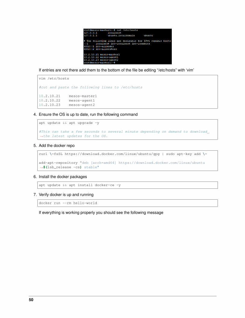
If entries are not there add them to the bottom of the file be editing “/etc/hosts” with ‘vim’
vim /etc/hosts
#cut and paste the following lines to /etc/hosts
10.2.10.21 mesos-master110.2.10.22 mesos-agent110.2.10.23 mesos-agent2
4. Ensure the OS is up to date, run the following command
apt update && apt upgrade -y
#This can take a few seconds to several minute depending on demand to download→˓the latest updates for the OS.
5. Add the docker repo
curl \-fsSL https://download.docker.com/linux/ubuntu/gpg | sudo apt-key add \-
add-apt-repository "deb [arch=amd64] https://download.docker.com/linux/ubuntu→˓$(lsb_release -cs) stable"
6. Install the docker packages
apt update && apt install docker-ce -y
7. Verify docker is up and running
docker run --rm hello-world
If everything is working properly you should see the following message
50

8. Install java for the mesos and marathon processes.
apt install -y openjdk-8-jdk
export JAVA_HOME=/usr/lib/jvm/java-8-openjdk-amd64/
4.2.2 Lab 2.2 - Setup the Master
Important: The following commands need to be run on the master only unless otherwise specified.
Install Mesos, Marathon and Zookeeper
1. Add the mesos/marathon repo
Run the following commands:
apt-key adv --keyserver keyserver.ubuntu.com --recv E56151BF
cat <<EOF >> /etc/apt/sources.list.d/mesosphere.listdeb http://repos.mesosphere.com/ubuntu $(lsb_release -cs) mainEOF
2. Install the mesos, marathon and zookeeper packages
apt update && apt install mesos marathon zookeeperd -y
Setup Zookeeper
Note: 2181 is zookeeper’s default port.
1. Setup a unique ID per zookeeper instance. Update /etc/zookeeper/conf/myid to 1, 2 or 3depending on the number of master nodes. In our case 1
51
echo 1 > /etc/zookeeper/conf/myid
2. Modify the zookeeper config file on each master
sed -i /^#server.1/s/#server.1=zookeeper1/server.1=10.2.10.21/ /etc/zookeeper/→˓conf/zoo.cfg
Setup Mesos
1. Create mesos ip file /etc/mesos-master/ip
echo "10.2.10.21" > /etc/mesos-master/ip
2. Create mesos hostname file /etc/mesos-master/hostname (specify the IP address of your node)
echo "10.2.10.21" > /etc/mesos-master/hostname
3. Change the quorum value to reflect our cluster size. It should be set over 50% of the number of masterinstances. In this case it should be 1 because we have only one master
echo 1 > /etc/mesos-master/quorum
4. Point zookeeper to the master instance. This is done in the file /etc/mesos/zk
echo "zk://10.2.10.21:2181/mesos" > /etc/mesos/zk
Setup Marathon
1. First we need to specify the zookeeper masters that marathon will connect to (for information andthings like scheduling). We can copy the previous file we setup for mesos:
echo "MARATHON_MASTER=`cat /etc/mesos/zk`" > /etc/default/marathon
2. We also need to have marathon store its own state in zookeper (since it runs on all three masters):
echo "MARATHON_ZK=zk://10.2.10.21:2181/marathon" >> /etc/default/marathon
Start your services
1. When you install mesos, the master and slave services are enabled (called mesos-master and mesos-slave). Here, we want our master to focus on this tasks so we need to disable the slave service. Dothis on all the master nodes:
systemctl stop mesos-slaveecho manual > /etc/init/mesos-slave.override
2. We need to restart zookeeper and start mesos-master and marathon process on all master nodes:
systemctl restart zookeeper
systemctl start mesos-mastersystemctl enable mesos-master
52
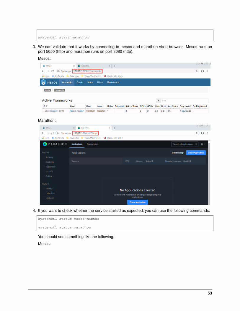
systemctl start marathon
3. We can validate that it works by connecting to mesos and marathon via a browser. Mesos runs onport 5050 (http) and marathon runs on port 8080 (http).
Mesos:
Marathon:
4. If you want to check whether the service started as expected, you can use the following commands:
systemctl status mesos-master
systemctl status marathon
You should see something like the following:
Mesos:
53

Marathon:
5. For more information about the marathon service, check the about section in marathon by clicking the? drop down in the upper right hand side of the marathon page.
6. If multiple masters were configured for high availability you can do the following to test the HA ofmarathon:
54
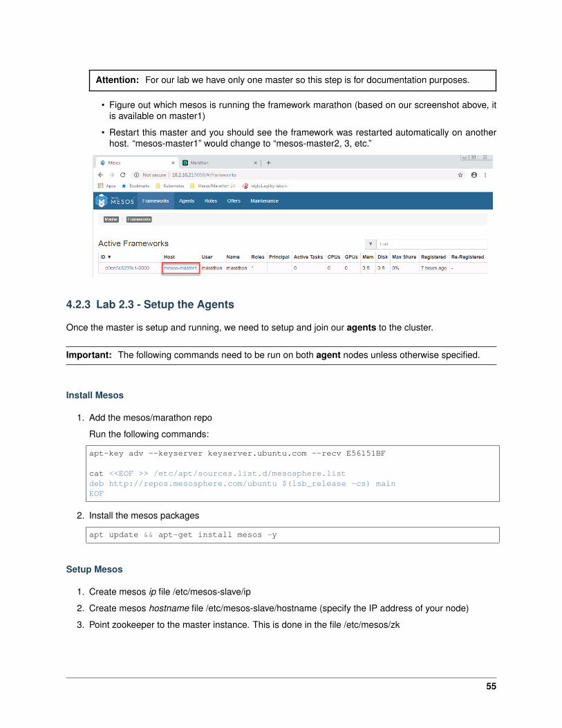
Attention: For our lab we have only one master so this step is for documentation purposes.
• Figure out which mesos is running the framework marathon (based on our screenshot above, itis available on master1)
• Restart this master and you should see the framework was restarted automatically on anotherhost. “mesos-master1” would change to “mesos-master2, 3, etc.”
4.2.3 Lab 2.3 - Setup the Agents
Once the master is setup and running, we need to setup and join our agents to the cluster.
Important: The following commands need to be run on both agent nodes unless otherwise specified.
Install Mesos
1. Add the mesos/marathon repo
Run the following commands:
apt-key adv --keyserver keyserver.ubuntu.com --recv E56151BF
cat <<EOF >> /etc/apt/sources.list.d/mesosphere.listdeb http://repos.mesosphere.com/ubuntu $(lsb_release -cs) mainEOF
2. Install the mesos packages
apt update && apt-get install mesos -y
Setup Mesos
1. Create mesos ip file /etc/mesos-slave/ip
2. Create mesos hostname file /etc/mesos-slave/hostname (specify the IP address of your node)
3. Point zookeeper to the master instance. This is done in the file /etc/mesos/zk
55
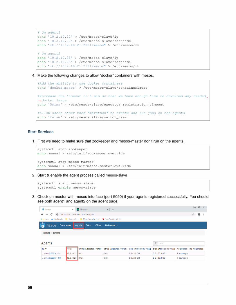
# On agent1echo "10.2.10.22" > /etc/mesos-slave/ipecho "10.2.10.22" > /etc/mesos-slave/hostnameecho "zk://10.2.10.21:2181/mesos" > /etc/mesos/zk
# On agent2echo "10.2.10.23" > /etc/mesos-slave/ipecho "10.2.10.23" > /etc/mesos-slave/hostnameecho "zk://10.2.10.21:2181/mesos" > /etc/mesos/zk
4. Make the following changes to allow “docker” containers with mesos.
#Add the ability to use docker containersecho 'docker,mesos' > /etc/mesos-slave/containerizers
#Increase the timeout to 5 min so that we have enough time to download any needed→˓docker imageecho '5mins' > /etc/mesos-slave/executor_registration_timeout
#Allow users other then "marathon" to create and run jobs on the agentsecho 'false' > /etc/mesos-slave/switch_user
Start Services
1. First we need to make sure that zookeeper and mesos-master don’t run on the agents.
systemctl stop zookeeperecho manual > /etc/init/zookeeper.override
systemctl stop mesos-masterecho manual > /etc/init/mesos.master.override
2. Start & enable the agent process called mesos-slave
systemctl start mesos-slavesystemctl enable mesos-slave
3. Check on master with mesos interface (port 5050) if your agents registered successfully. You shouldsee both agent1 and agent2 on the agent page.
56
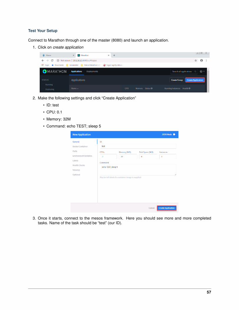
Test Your Setup
Connect to Marathon through one of the master (8080) and launch an application.
1. Click on create application
2. Make the following settings and click “Create Application”
• ID: test
• CPU: 0.1
• Memory: 32M
• Command: echo TEST; sleep 5
3. Once it starts, connect to the mesos framework. Here you should see more and more completedtasks. Name of the task should be “test” (our ID).
57
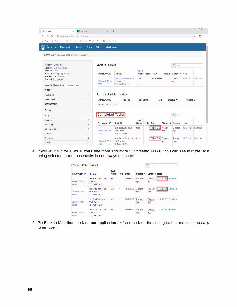
4. If you let it run for a while, you’ll see more and more “Completed Tasks”. You can see that the Hostbeing selected to run those tasks is not always the same.
5. Go Back to Marathon, click on our application test and click on the setting button and select destroyto remove it.
58

Launch A Container
To test our containers from marathon. We will start a simple apache container.
1. Click on create an application, switch to JSON mode and replace the default 8 lines of json with thefollowing and Click “Create Application”
Note: This may takes some time since we will have to retrieve the image first
{"id": "my-website","cpus": 0.5,"mem": 32.0,"container": {
"type": "DOCKER","docker": {
"image": "eboraas/apache-php","network": "BRIDGE","portMappings": [
{ "containerPort": 80, "hostPort": 0 }]
}}
}
59
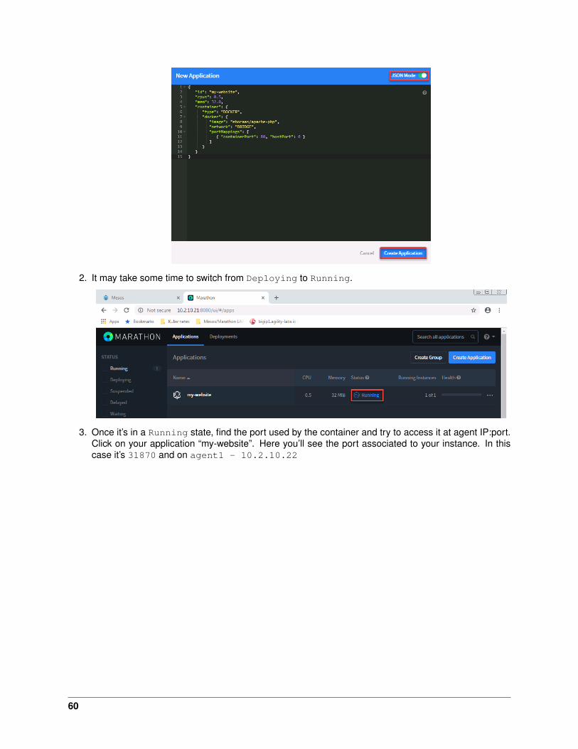
2. It may take some time to switch from Deploying to Running.
3. Once it’s in a Running state, find the port used by the container and try to access it at agent IP:port.Click on your application “my-website”. Here you’ll see the port associated to your instance. In thiscase it’s 31870 and on agent1 - 10.2.10.22
60
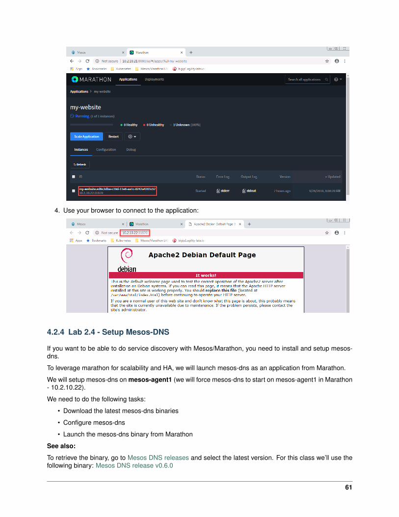
4. Use your browser to connect to the application:
4.2.4 Lab 2.4 - Setup Mesos-DNS
If you want to be able to do service discovery with Mesos/Marathon, you need to install and setup mesos-dns.
To leverage marathon for scalability and HA, we will launch mesos-dns as an application from Marathon.
We will setup mesos-dns on mesos-agent1 (we will force mesos-dns to start on mesos-agent1 in Marathon- 10.2.10.22).
We need to do the following tasks:
• Download the latest mesos-dns binaries
• Configure mesos-dns
• Launch the mesos-dns binary from Marathon
See also:
To retrieve the binary, go to Mesos DNS releases and select the latest version. For this class we’ll use thefollowing binary: Mesos DNS release v0.6.0
61
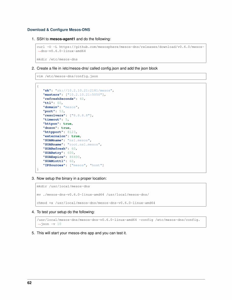
Download & Configure Mesos-DNS
1. SSH to mesos-agent1 and do the following:
curl -O -L https://github.com/mesosphere/mesos-dns/releases/download/v0.6.0/mesos-→˓dns-v0.6.0-linux-amd64
mkdir /etc/mesos-dns
2. Create a file in /etc/mesos-dns/ called config.json and add the json block
vim /etc/mesos-dns/config.json
{"zk": "zk://10.2.10.21:2181/mesos","masters": ["10.2.10.21:5050"],"refreshSeconds": 60,"ttl": 60,"domain": "mesos","port": 53,"resolvers": ["8.8.8.8"],"timeout": 5,"httpon": true,"dnson": true,"httpport": 8123,"externalon": true,"SOAMname": "ns1.mesos","SOARname": "root.ns1.mesos","SOARefresh": 60,"SOARetry": 600,"SOAExpire": 86400,"SOAMinttl": 60,"IPSources": ["mesos", "host"]
}
3. Now setup the binary in a proper location:
mkdir /usr/local/mesos-dns
mv ./mesos-dns-v0.6.0-linux-amd64 /usr/local/mesos-dns/
chmod +x /usr/local/mesos-dns/mesos-dns-v0.6.0-linux-amd64
4. To test your setup do the following:
/usr/local/mesos-dns/mesos-dns-v0.6.0-linux-amd64 -config /etc/mesos-dns/config.→˓json -v 10
5. This will start your mesos-dns app and you can test it.
62

6. You can now test your dns setup. Open a new command prompt from the windows jumpbox and startnslookup
Microsoft Windows [Version 6.1.7601]Copyright (c) 2009 Microsoft Corporation. All rights reserved.
C:\Users\user>nslookupDefault Server: b.resolvers.Level3.netAddress: 4.2.2.2
> server 10.2.10.22Default Server: [10.2.10.22]Address: 10.2.10.22
> www.google.comServer: [10.2.10.22]Address: 10.2.10.22
Non-authoritative answer:Name: www.google.comAddresses: 2607:f8b0:4007:80e::2004
172.217.14.100
> master.mesosServer: [10.2.10.22]Address: 10.2.10.22
Name: master.mesosAddress: 10.2.10.21
>
7. Stop your test mesos-dns app by typing “CTRL-c”
63

Warning: The next steps will fail if you don’t stop your test mesos-dns app
Launch Mesos-DNS In Marathon
1. Launch the mesos-dns image in marathon. Connect to marathon, click on Create Application andenable JSON Mode. Copy the following JSON block over the default and click Create Application.
{"cmd": "/usr/local/mesos-dns/mesos-dns-v0.6.0-linux-amd64 -config=/etc/mesos-
→˓dns/config.json -v=10","cpus": 0.2,"mem": 256,"id": "mesos-dns","instances": 1,"constraints": [["hostname", "CLUSTER", "10.2.10.22"]]
}
2. Update /etc/resolv.conf on all agents by adding our mesos-dns nameserver to our /etc/resolv.conffile. SSH to mesos-agent1 & 2.
sed -i /nameserver/s/.*/"nameserver 10.2.10.22"/ /etc/resolv.conf
Note: If you have deployed your instances in a cloud like AWS, it is likely that you’ll lose your DNS setupafter a reboot. If you want to make your changes persist, you need to update /etc/dhcp/dhclient.conf tosupersede the dhcp setup. More information here: Static DNS server in a EC2 instance
Test Mesos-DNS
To test our Mesos DNS setup, we will start a new application and check if it automatically gets a DNS name.
1. Start a new app in marathon:
{"id": "app-test-dns","cpus": 0.5,"mem": 32.0,"container": {
"type": "DOCKER","docker": {
"image": "eboraas/apache-php","network": "BRIDGE","portMappings": [
{ "containerPort": 80, "hostPort": 0 }]
}}
}
2. Once it’s running, go to one of your slaves and run ping app-test-dns.marathon.mesos. It should workand return the agent IP.
64
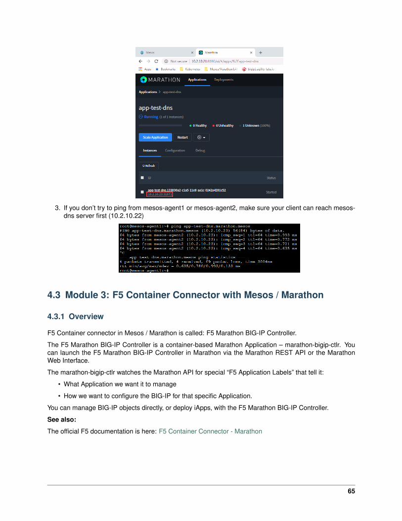
3. If you don’t try to ping from mesos-agent1 or mesos-agent2, make sure your client can reach mesos-dns server first (10.2.10.22)
4.3 Module 3: F5 Container Connector with Mesos / Marathon
4.3.1 Overview
F5 Container connector in Mesos / Marathon is called: F5 Marathon BIG-IP Controller.
The F5 Marathon BIG-IP Controller is a container-based Marathon Application – marathon-bigip-ctlr. Youcan launch the F5 Marathon BIG-IP Controller in Marathon via the Marathon REST API or the MarathonWeb Interface.
The marathon-bigip-ctlr watches the Marathon API for special “F5 Application Labels” that tell it:
• What Application we want it to manage
• How we want to configure the BIG-IP for that specific Application.
You can manage BIG-IP objects directly, or deploy iApps, with the F5 Marathon BIG-IP Controller.
See also:
The official F5 documentation is here: F5 Container Connector - Marathon
65
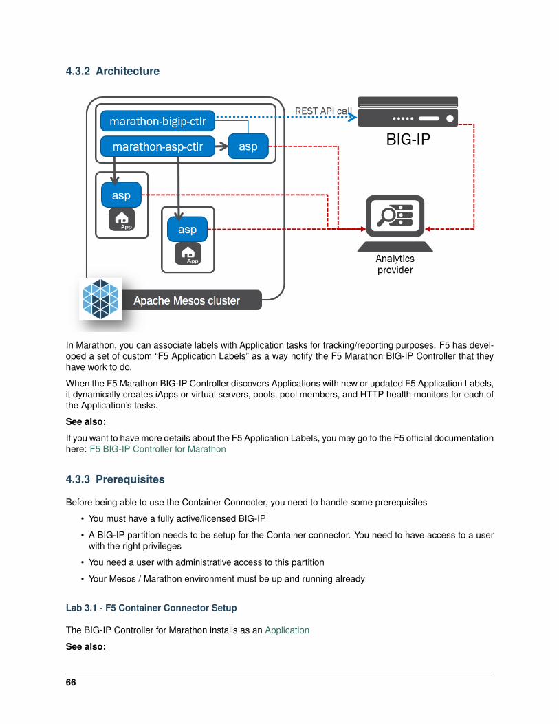
4.3.2 Architecture
In Marathon, you can associate labels with Application tasks for tracking/reporting purposes. F5 has devel-oped a set of custom “F5 Application Labels” as a way notify the F5 Marathon BIG-IP Controller that theyhave work to do.
When the F5 Marathon BIG-IP Controller discovers Applications with new or updated F5 Application Labels,it dynamically creates iApps or virtual servers, pools, pool members, and HTTP health monitors for each ofthe Application’s tasks.
See also:
If you want to have more details about the F5 Application Labels, you may go to the F5 official documentationhere: F5 BIG-IP Controller for Marathon
4.3.3 Prerequisites
Before being able to use the Container Connecter, you need to handle some prerequisites
• You must have a fully active/licensed BIG-IP
• A BIG-IP partition needs to be setup for the Container connector. You need to have access to a userwith the right privileges
• You need a user with administrative access to this partition
• Your Mesos / Marathon environment must be up and running already
Lab 3.1 - F5 Container Connector Setup
The BIG-IP Controller for Marathon installs as an Application
See also:
66
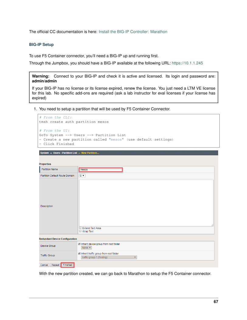
The official CC documentation is here: Install the BIG-IP Controller: Marathon
BIG-IP Setup
To use F5 Container connector, you’ll need a BIG-IP up and running first.
Through the Jumpbox, you should have a BIG-IP available at the following URL: https://10.1.1.245
Warning: Connect to your BIG-IP and check it is active and licensed. Its login and password are:admin/admin
If your BIG-IP has no license or its license expired, renew the license. You just need a LTM VE licensefor this lab. No specific add-ons are required (ask a lab instructor for eval licenses if your license hasexpired)
1. You need to setup a partition that will be used by F5 Container Connector.
# From the CLI:tmsh create auth partition mesos
# From the UI:GoTo System --> Users --> Partition List- Create a new partition called "mesos" (use default settings)- Click Finished
With the new partition created, we can go back to Marathon to setup the F5 Container connector.
67
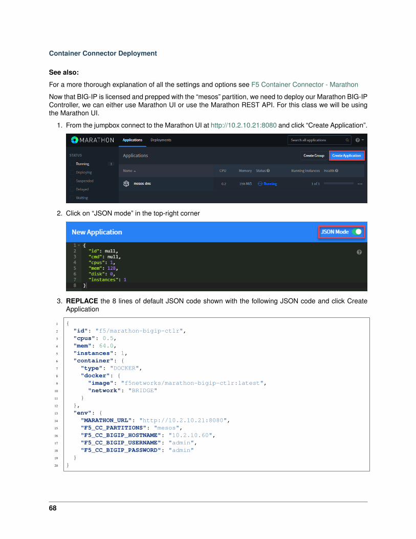
Container Connector Deployment
See also:
For a more thorough explanation of all the settings and options see F5 Container Connector - Marathon
Now that BIG-IP is licensed and prepped with the “mesos” partition, we need to deploy our Marathon BIG-IPController, we can either use Marathon UI or use the Marathon REST API. For this class we will be usingthe Marathon UI.
1. From the jumpbox connect to the Marathon UI at http://10.2.10.21:8080 and click “Create Application”.
2. Click on “JSON mode” in the top-right corner
3. REPLACE the 8 lines of default JSON code shown with the following JSON code and click CreateApplication
1 {2 "id": "f5/marathon-bigip-ctlr",3 "cpus": 0.5,4 "mem": 64.0,5 "instances": 1,6 "container": {7 "type": "DOCKER",8 "docker": {9 "image": "f5networks/marathon-bigip-ctlr:latest",
10 "network": "BRIDGE"11 }12 },13 "env": {14 "MARATHON_URL": "http://10.2.10.21:8080",15 "F5_CC_PARTITIONS": "mesos",16 "F5_CC_BIGIP_HOSTNAME": "10.2.10.60",17 "F5_CC_BIGIP_USERNAME": "admin",18 "F5_CC_BIGIP_PASSWORD": "admin"19 }20 }
68
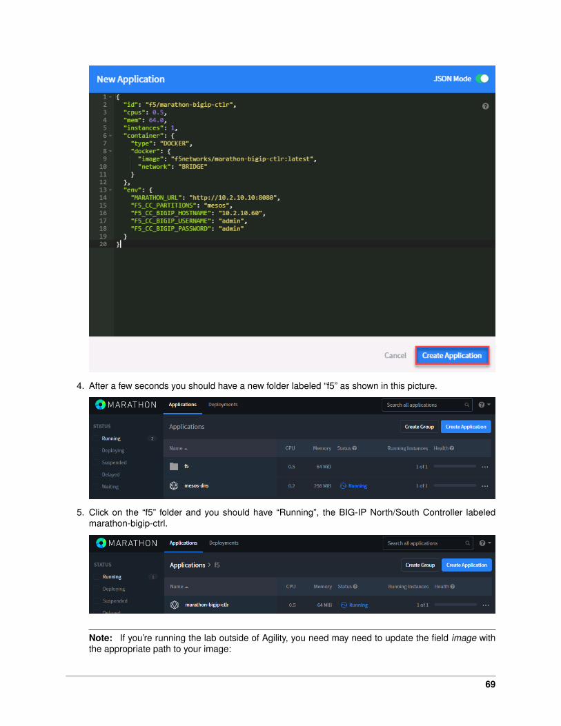
4. After a few seconds you should have a new folder labeled “f5” as shown in this picture.
5. Click on the “f5” folder and you should have “Running”, the BIG-IP North/South Controller labeledmarathon-bigip-ctrl.
Note: If you’re running the lab outside of Agility, you need may need to update the field image withthe appropriate path to your image:
69

• Load it on all your agents/nodes with the docker pull command. sudo docker pullf5networks/marathon-bigip-ctlr:latest for the latest version.
• Load it on a system and push it into your registry if needed.
• If your Mesos environment use authentication, here is a link explaining how to handle authenti-cation with the Marathon BIG-IP Controller: Set up authentication to your secure DC/OS cluster
Troubleshooting
If you need to troubleshoot your container, you have two different ways to check the logs of your container,Marathon UI or Docker command.
1. Using the Marathon UI Click on Applications –> the f5 folder –> marathon-bigip-ctlr. From here youcan download and view the logs from the text editor of choice.
You should see something like this:
2. Using docker log command: You need to identify where the Controller is running. From the previousstep we can see it’s running on 10.2.10.22 (which is mesos-agent1).
Connect via SSH to mesos-agent1 and run the following commands:
70

sudo docker ps
This command will give us the Controllers Container ID, here it is: 4fdee0a49dcb. We need this ID forthe next command.
To check the logs of our Controller:
sudo docker logs 4fdee0a49dcb
3. You can connect to your container with docker as well:
sudo docker exec -it 4fdee0a49dcb /bin/sh
cd /app
ls -la
exit
Lab 3.2 - F5 Container Connector Usage
Now that our container connector is up and running, let’s deploy an application and leverage our F5 CC.
For this lab we’ll use a simple pre-configured docker image called “f5-hello-world”. It can be found on dockerhub at f5devcentral/f5-hello-world
App Deployment
From the jumpbox connect to the Marathon UI at http://10.2.10.21:8080 and click “Create Application”.
1. Click on “JSON mode” in the top-right corner
71

2. REPLACE the 8 lines of default JSON code shown with the following JSON code and click CreateApplication
1 {2 "id": "f5-hello-world",3 "cpus": 0.1,4 "mem": 128.0,5 "instances": 2,6 "container": {7 "type": "DOCKER",8 "docker": {9 "image": "f5devcentral/f5-hello-world:latest",
10 "network": "BRIDGE",11 "forcePullImage": false,12 "portMappings": [13 { "containerPort": 8080, "hostPort": 0, "protocol": "tcp" }14 ]15 }16 },17 "labels": {18 "F5_PARTITION": "mesos",19 "F5_0_BIND_ADDR": "10.2.10.81",20 "F5_0_MODE": "http",21 "F5_0_BALANCE": "round-robin",22 "F5_0_PORT": "80"23 },24 "healthChecks": [25 {26 "protocol": "HTTP",27 "portIndex": 0,28 "path": "/",29 "gracePeriodSeconds": 5,30 "intervalSeconds": 16,31 "maxConsecutiveFailures": 332 }33 ]34 }
3. F5-Hello-World is “Deploying”
Note: The JSON app definition specified several things:
(a) What container image to use (line 9)
(b) The BIG-IP configuration (Partition, VS IP, VS Port).
(c) The Marathon health check for this app. The BIG-IP will replicate those health checks.
(d) The number of instances (line 5)
72
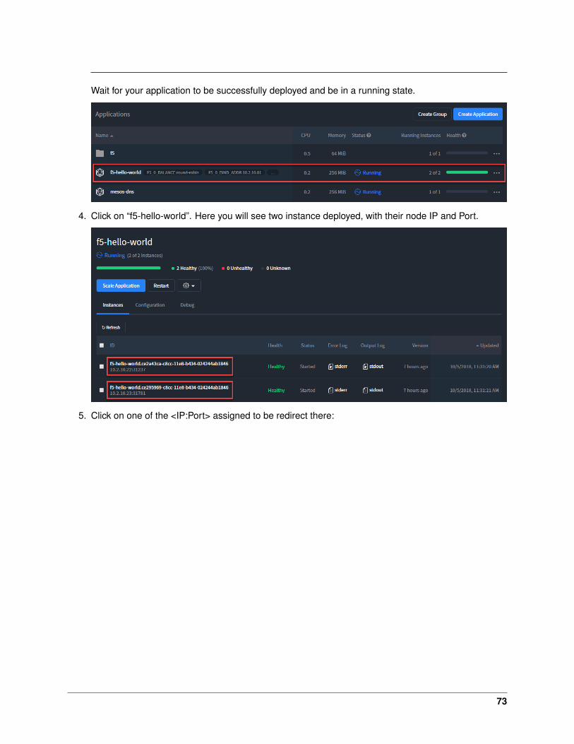
Wait for your application to be successfully deployed and be in a running state.
4. Click on “f5-hello-world”. Here you will see two instance deployed, with their node IP and Port.
5. Click on one of the <IP:Port> assigned to be redirect there:
73
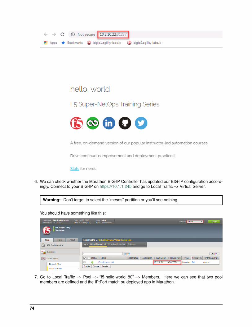
6. We can check whether the Marathon BIG-IP Controller has updated our BIG-IP configuration accord-ingly. Connect to your BIG-IP on https://10.1.1.245 and go to Local Traffic –> Virtual Server.
Warning: Don’t forget to select the “mesos” partition or you’ll see nothing.
You should have something like this:
7. Go to Local Traffic –> Pool –> “f5-hello-world_80” –> Members. Here we can see that two poolmembers are defined and the IP:Port match ou deployed app in Marathon.
74

8. You should be able to access the application. In your browser try to connect to http://10.2.10.81
9. Scale the f5-hello-world app. Go back to the Marathon UI (http://10.2.10.21:8080). Go to Applications–> “f5-hello-world” and click “Scale Application”.
Let’s increase the number from 2 to 10 instances and click on “Scale Application”.
75
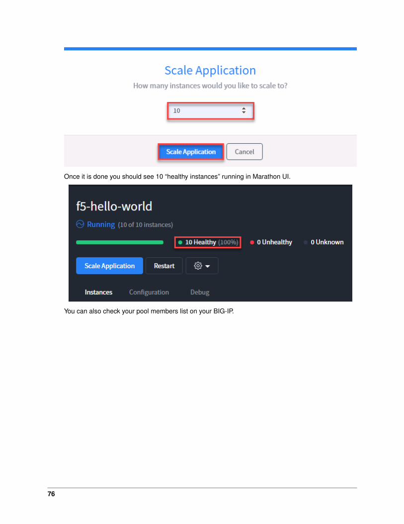
Once it is done you should see 10 “healthy instances” running in Marathon UI.
You can also check your pool members list on your BIG-IP.
76

As we can see, the Marathon BIG-IP Controller is adapting the pool members setup based on thenumber of instances delivering this application automatically.
10. Scale back the application to 2 to save resources for the next labs.
Expected time to complete: 1 hours
Attention: MODULE 2: BUILD A MESOS / MARATHON CLUSTER CAN BE SKIPPED. THEBLUEPRINT IS PRE-CONFIGURED WITH A WORKING CLUSTER. THIS MODULE IS FOR DOC-UMENTION PURPOSES ONLY.
4.4 Lab Setup
We will leverage the following setup to configure the Mesos / Marathon environment.
77

Hostname IP-ADDR Credentialsjumpbox 10.1.1.250 user/Student!Agility!bigip1 10.1.1.245
10.2.10.60admin/adminroot/default
mesos-master1 10.2.10.21 ubuntu/ubunturoot/default
mesos-agent1 10.2.10.22 ubuntu/ubunturoot/default
mesos-agent2 10.2.10.23 ubuntu/ubunturoot/default
78
5Class 4: Introduction to RedHat OpenShift
This introductory class covers the following topics:
5.1 Module 1: Build an Openshift Cluster
Attention: THIS MODULE CAN BE SKIPPED. THE BLUEPRINT IS PRE-CONFIGURED WITH AWORKING CLUSTER. THIS MODULE IS FOR DOCUMENTION PURPOSES ONLY.
In this module, we will build a 3 node cluster (1x master and 2x nodes) utilizing CentOS server images.
As a reminder, in this module, our cluster setup is:
Hostname IP-ADDR Roleose-master1 10.3.10.21 Masterose-node1 10.3.10.22 Nodeose-node2 10.3.10.23 Node
5.1.1 Lab 1.1 - Prep CentOS
Note:
• This installation will utilize centOS v7.5.
• SSH keys were configured to allow the jumphost to login without a passwd as well as between themaster & nodes to facilitate the Ansible playbooks.
Important: The following commands need to be run on all three nodes unless otherwise specified.
1. From the jumpbox open mRemoteNG and start a session to each of the following servers. Thesessions are pre-configured to connect with the default user “centos”.
• ose-master1
79
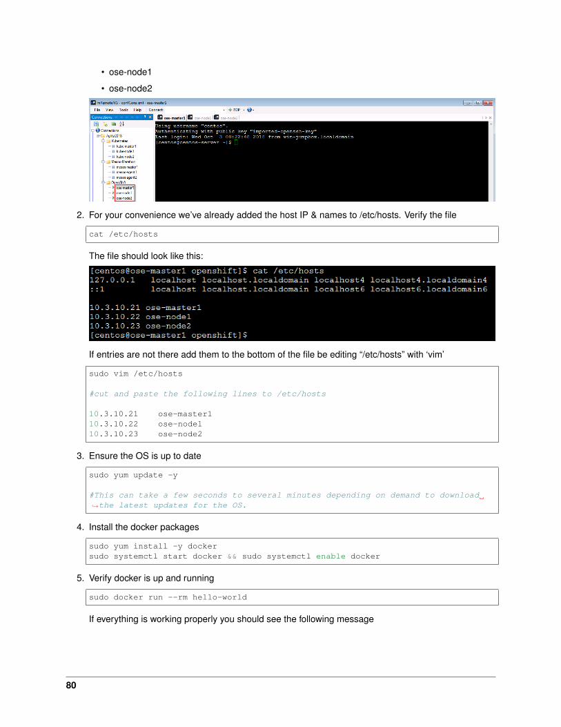
• ose-node1
• ose-node2
2. For your convenience we’ve already added the host IP & names to /etc/hosts. Verify the file
cat /etc/hosts
The file should look like this:
If entries are not there add them to the bottom of the file be editing “/etc/hosts” with ‘vim’
sudo vim /etc/hosts
#cut and paste the following lines to /etc/hosts
10.3.10.21 ose-master110.3.10.22 ose-node110.3.10.23 ose-node2
3. Ensure the OS is up to date
sudo yum update -y
#This can take a few seconds to several minutes depending on demand to download→˓the latest updates for the OS.
4. Install the docker packages
sudo yum install -y dockersudo systemctl start docker && sudo systemctl enable docker
5. Verify docker is up and running
sudo docker run --rm hello-world
If everything is working properly you should see the following message
80

5.1.2 Lab 1.2 - Install Openshift
Important: The following commands need to be run on the master only, unless otherwise specified.
1. Install Ansible
sudo yum install -y epel-releasesudo yum install -y ansible
2. Disable “epel-release”
vim /etc/yum.repos.d/epel.repo
# Change the value enabled=1 to 0 (zero).
Note: This is done to prevent future OS updates from including packages from outside the standardpackages.
3. Prep openshift AUTH
sudo mkdir -p /etc/origin/master/sudo touch /etc/origin/master/htpasswd
4. Clone the openshift-ansible repo
git clone -b release-3.10 https://github.com/openshift/openshift-ansible.git→˓$HOME/openshift-ansible
81
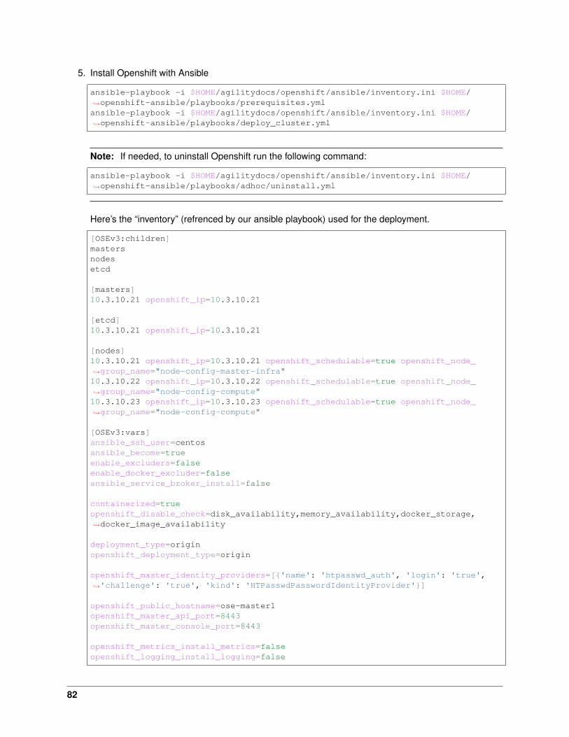
5. Install Openshift with Ansible
ansible-playbook -i $HOME/agilitydocs/openshift/ansible/inventory.ini $HOME/→˓openshift-ansible/playbooks/prerequisites.ymlansible-playbook -i $HOME/agilitydocs/openshift/ansible/inventory.ini $HOME/→˓openshift-ansible/playbooks/deploy_cluster.yml
Note: If needed, to uninstall Openshift run the following command:
ansible-playbook -i $HOME/agilitydocs/openshift/ansible/inventory.ini $HOME/→˓openshift-ansible/playbooks/adhoc/uninstall.yml
Here’s the “inventory” (refrenced by our ansible playbook) used for the deployment.
[OSEv3:children]mastersnodesetcd
[masters]10.3.10.21 openshift_ip=10.3.10.21
[etcd]10.3.10.21 openshift_ip=10.3.10.21
[nodes]10.3.10.21 openshift_ip=10.3.10.21 openshift_schedulable=true openshift_node_→˓group_name="node-config-master-infra"10.3.10.22 openshift_ip=10.3.10.22 openshift_schedulable=true openshift_node_→˓group_name="node-config-compute"10.3.10.23 openshift_ip=10.3.10.23 openshift_schedulable=true openshift_node_→˓group_name="node-config-compute"
[OSEv3:vars]ansible_ssh_user=centosansible_become=trueenable_excluders=falseenable_docker_excluder=falseansible_service_broker_install=false
containerized=trueopenshift_disable_check=disk_availability,memory_availability,docker_storage,→˓docker_image_availability
deployment_type=originopenshift_deployment_type=origin
openshift_master_identity_providers=[{'name': 'htpasswd_auth', 'login': 'true',→˓'challenge': 'true', 'kind': 'HTPasswdPasswordIdentityProvider'}]
openshift_public_hostname=ose-master1openshift_master_api_port=8443openshift_master_console_port=8443
openshift_metrics_install_metrics=falseopenshift_logging_install_logging=false
82
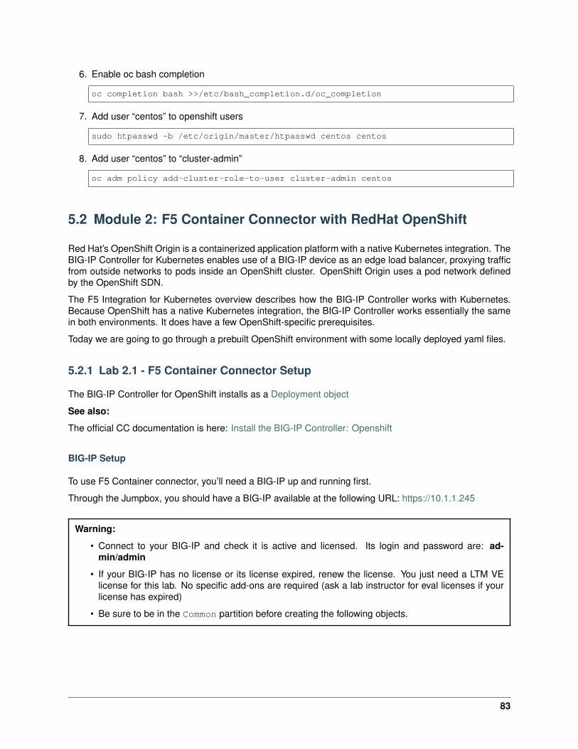
6. Enable oc bash completion
oc completion bash >>/etc/bash_completion.d/oc_completion
7. Add user “centos” to openshift users
sudo htpasswd -b /etc/origin/master/htpasswd centos centos
8. Add user “centos” to “cluster-admin”
oc adm policy add-cluster-role-to-user cluster-admin centos
5.2 Module 2: F5 Container Connector with RedHat OpenShift
Red Hat’s OpenShift Origin is a containerized application platform with a native Kubernetes integration. TheBIG-IP Controller for Kubernetes enables use of a BIG-IP device as an edge load balancer, proxying trafficfrom outside networks to pods inside an OpenShift cluster. OpenShift Origin uses a pod network definedby the OpenShift SDN.
The F5 Integration for Kubernetes overview describes how the BIG-IP Controller works with Kubernetes.Because OpenShift has a native Kubernetes integration, the BIG-IP Controller works essentially the samein both environments. It does have a few OpenShift-specific prerequisites.
Today we are going to go through a prebuilt OpenShift environment with some locally deployed yaml files.
5.2.1 Lab 2.1 - F5 Container Connector Setup
The BIG-IP Controller for OpenShift installs as a Deployment object
See also:
The official CC documentation is here: Install the BIG-IP Controller: Openshift
BIG-IP Setup
To use F5 Container connector, you’ll need a BIG-IP up and running first.
Through the Jumpbox, you should have a BIG-IP available at the following URL: https://10.1.1.245
Warning:
• Connect to your BIG-IP and check it is active and licensed. Its login and password are: ad-min/admin
• If your BIG-IP has no license or its license expired, renew the license. You just need a LTM VElicense for this lab. No specific add-ons are required (ask a lab instructor for eval licenses if yourlicense has expired)
• Be sure to be in the Common partition before creating the following objects.
83

1. You need to setup a partition that will be used by F5 Container Connector.
# From the CLI:tmsh create auth partition ose
# From the UI:GoTo System --> Users --> Partition List- Create a new partition called "ose" (use default settings)- Click Finished
2. Create a vxlan tunnel profile
# From the CLI:tmsh create net tunnel vxlan ose-vxlan {app-service none flooding-type multipoint}
# From the UI:GoTo Network --> Tunnels --> Profiles --> VXLAN- Create a new profile called "ose-vxlan"- Set the Flooding Type = Multipoint- Click Finished
84

3. Create a vxlan tunnel
# From the CLI:tmsh create net tunnel tunnel ose-tunnel {key 0 local-address 10.3.10.60 profile→˓ose-vxlan}
# From the UI:GoTo Network --> Tunnels --> Tunnel List- Create a new tunnel called "ose-tunnel"- Set the Local Address to 10.3.10.60- Set the Profile to the one previously created called "ose-vxlan"- Click Finished
Container Connector Deployment
See also:
For a more thorough explanation of all the settings and options see F5 Container Connector - Openshift
85
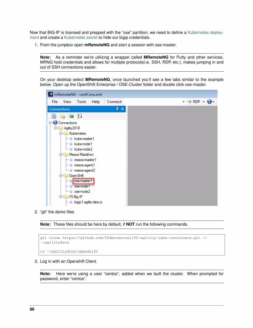
Now that BIG-IP is licensed and prepped with the “ose” partition, we need to define a Kubernetes deploy-ment and create a Kubernetes secret to hide our bigip credentials.
1. From the jumpbox open mRemoteNG and start a session with ose-master.
Note: As a reminder we’re utilizing a wrapper called MRemoteNG for Putty and other services.MRNG hold credentials and allows for multiple protocols(i.e. SSH, RDP, etc.), makes jumping in andout of SSH connections easier.
On your desktop select MRemoteNG, once launched you’ll see a few tabs similar to the examplebelow. Open up the OpenShift Enterprise / OSE-Cluster folder and double click ose-master.
2. “git” the demo files
Note: These files should be here by default, if NOT run the following commands.
git clone https://github.com/f5devcentral/f5-agility-labs-containers.git ~/→˓agilitydocs
cd ~/agilitydocs/openshift
3. Log in with an Openshift Client.
Note: Here we’re using a user “centos”, added when we built the cluster. When prompted forpassword, enter “centos”.
86
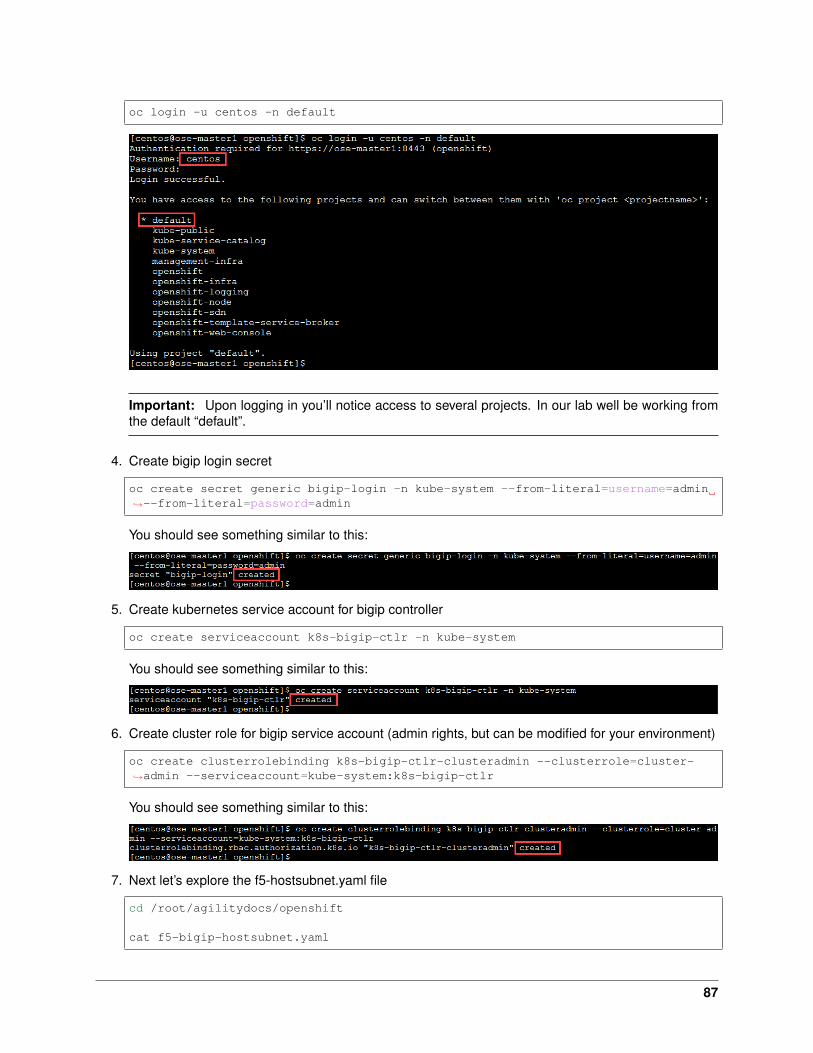
oc login -u centos -n default
Important: Upon logging in you’ll notice access to several projects. In our lab well be working fromthe default “default”.
4. Create bigip login secret
oc create secret generic bigip-login -n kube-system --from-literal=username=admin→˓--from-literal=password=admin
You should see something similar to this:
5. Create kubernetes service account for bigip controller
oc create serviceaccount k8s-bigip-ctlr -n kube-system
You should see something similar to this:
6. Create cluster role for bigip service account (admin rights, but can be modified for your environment)
oc create clusterrolebinding k8s-bigip-ctlr-clusteradmin --clusterrole=cluster-→˓admin --serviceaccount=kube-system:k8s-bigip-ctlr
You should see something similar to this:
7. Next let’s explore the f5-hostsubnet.yaml file
cd /root/agilitydocs/openshift
cat f5-bigip-hostsubnet.yaml
87

You’ll see a config file similar to this:
1 apiVersion: v12 kind: HostSubnet3 metadata:4 name: openshift-f5-node5 annotations:6 pod.network.openshift.io/fixed-vnid-host: "0"7 host: openshift-f5-node8 hostIP: 10.3.10.609 subnet: "10.131.0.0/23"
Attention: This YAML file creates an OpenShift Node and the Host is the BIG-IP with an assigned/23 subnet of IP 10.131.0.0 (3 imagas down).
8. Next let’s look at the current cluster, you should see 3 members (1 master, 2 nodes)
oc get hostsubnet
9. Now create the connector to the BIG-IP device, then look before and after at the attached devices
oc create -f f5-bigip-hostsubnet.yaml
You should see a successful creation of a new OpenShift Node.
10. At this point nothing has been done to the BIG-IP, this only was done in the OpenShift environment.
oc get hostsubnet
You should now see OpenShift configured to communicate with the BIG-IP
Important: The Subnet assignment, in this case is 10.131.0.0/23, was assigned by the subnet:“10.131.0.0/23” line in “HostSubnet” yaml file.
Note: In this lab we’re manually assigning a subnet. We have the option to let openshift auto assignths by removing subnet: “10.131.0.0/23” line at the end of the “hostsubnet” yaml file and setting the
88
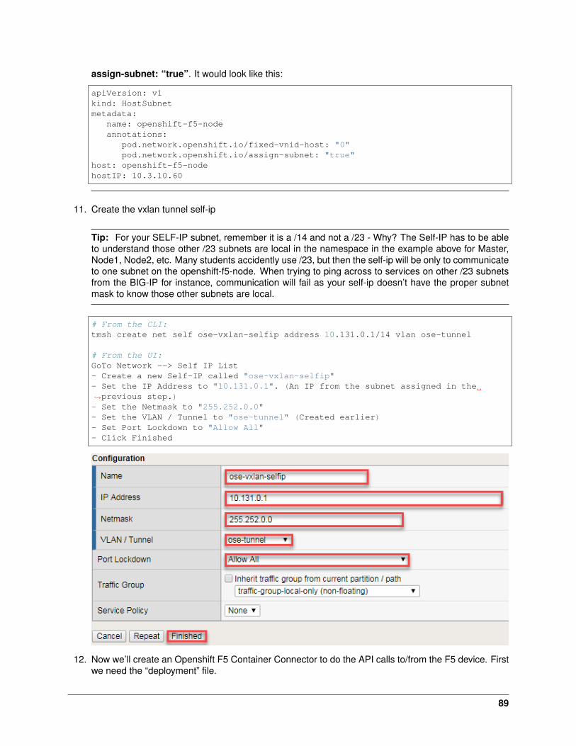
assign-subnet: “true”. It would look like this:
apiVersion: v1kind: HostSubnetmetadata:
name: openshift-f5-nodeannotations:
pod.network.openshift.io/fixed-vnid-host: "0"pod.network.openshift.io/assign-subnet: "true"
host: openshift-f5-nodehostIP: 10.3.10.60
11. Create the vxlan tunnel self-ip
Tip: For your SELF-IP subnet, remember it is a /14 and not a /23 - Why? The Self-IP has to be ableto understand those other /23 subnets are local in the namespace in the example above for Master,Node1, Node2, etc. Many students accidently use /23, but then the self-ip will be only to communicateto one subnet on the openshift-f5-node. When trying to ping across to services on other /23 subnetsfrom the BIG-IP for instance, communication will fail as your self-ip doesn’t have the proper subnetmask to know those other subnets are local.
# From the CLI:tmsh create net self ose-vxlan-selfip address 10.131.0.1/14 vlan ose-tunnel
# From the UI:GoTo Network --> Self IP List- Create a new Self-IP called "ose-vxlan-selfip"- Set the IP Address to "10.131.0.1". (An IP from the subnet assigned in the→˓previous step.)- Set the Netmask to "255.252.0.0"- Set the VLAN / Tunnel to "ose-tunnel" (Created earlier)- Set Port Lockdown to "Allow All"- Click Finished
12. Now we’ll create an Openshift F5 Container Connector to do the API calls to/from the F5 device. Firstwe need the “deployment” file.
89
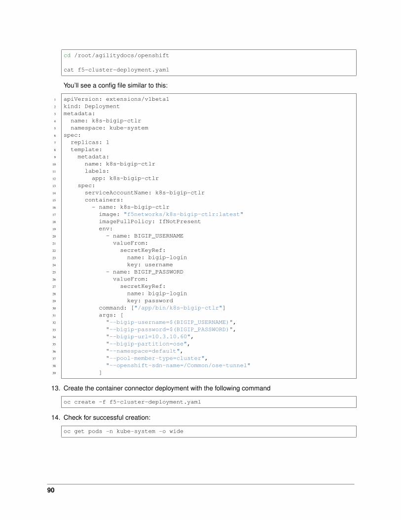
cd /root/agilitydocs/openshift
cat f5-cluster-deployment.yaml
You’ll see a config file similar to this:
1 apiVersion: extensions/v1beta12 kind: Deployment3 metadata:4 name: k8s-bigip-ctlr5 namespace: kube-system6 spec:7 replicas: 18 template:9 metadata:
10 name: k8s-bigip-ctlr11 labels:12 app: k8s-bigip-ctlr13 spec:14 serviceAccountName: k8s-bigip-ctlr15 containers:16 - name: k8s-bigip-ctlr17 image: "f5networks/k8s-bigip-ctlr:latest"18 imagePullPolicy: IfNotPresent19 env:20 - name: BIGIP_USERNAME21 valueFrom:22 secretKeyRef:23 name: bigip-login24 key: username25 - name: BIGIP_PASSWORD26 valueFrom:27 secretKeyRef:28 name: bigip-login29 key: password30 command: ["/app/bin/k8s-bigip-ctlr"]31 args: [32 "--bigip-username=$(BIGIP_USERNAME)",33 "--bigip-password=$(BIGIP_PASSWORD)",34 "--bigip-url=10.3.10.60",35 "--bigip-partition=ose",36 "--namespace=default",37 "--pool-member-type=cluster",38 "--openshift-sdn-name=/Common/ose-tunnel"39 ]
13. Create the container connector deployment with the following command
oc create -f f5-cluster-deployment.yaml
14. Check for successful creation:
oc get pods -n kube-system -o wide
90
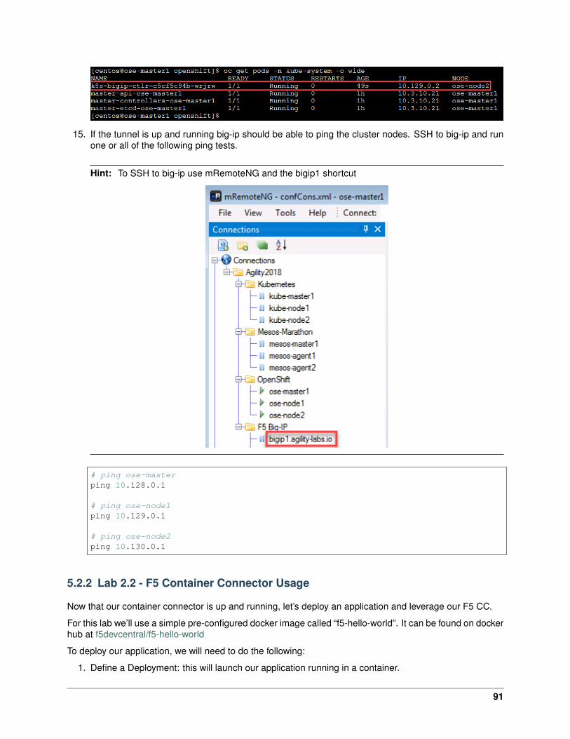
15. If the tunnel is up and running big-ip should be able to ping the cluster nodes. SSH to big-ip and runone or all of the following ping tests.
Hint: To SSH to big-ip use mRemoteNG and the bigip1 shortcut
# ping ose-masterping 10.128.0.1
# ping ose-node1ping 10.129.0.1
# ping ose-node2ping 10.130.0.1
5.2.2 Lab 2.2 - F5 Container Connector Usage
Now that our container connector is up and running, let’s deploy an application and leverage our F5 CC.
For this lab we’ll use a simple pre-configured docker image called “f5-hello-world”. It can be found on dockerhub at f5devcentral/f5-hello-world
To deploy our application, we will need to do the following:
1. Define a Deployment: this will launch our application running in a container.
91
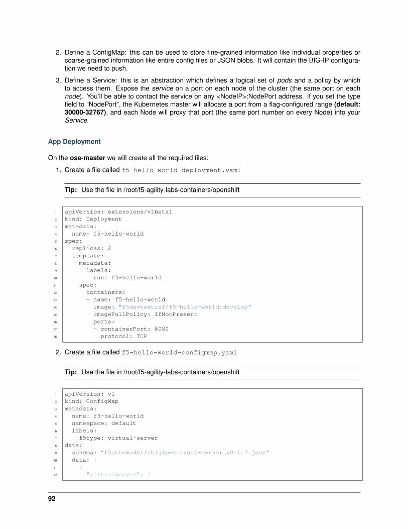
2. Define a ConfigMap: this can be used to store fine-grained information like individual properties orcoarse-grained information like entire config files or JSON blobs. It will contain the BIG-IP configura-tion we need to push.
3. Define a Service: this is an abstraction which defines a logical set of pods and a policy by whichto access them. Expose the service on a port on each node of the cluster (the same port on eachnode). You’ll be able to contact the service on any <NodeIP>:NodePort address. If you set the typefield to “NodePort”, the Kubernetes master will allocate a port from a flag-configured range (default:30000-32767), and each Node will proxy that port (the same port number on every Node) into yourService.
App Deployment
On the ose-master we will create all the required files:
1. Create a file called f5-hello-world-deployment.yaml
Tip: Use the file in /root/f5-agility-labs-containers/openshift
1 apiVersion: extensions/v1beta12 kind: Deployment3 metadata:4 name: f5-hello-world5 spec:6 replicas: 27 template:8 metadata:9 labels:
10 run: f5-hello-world11 spec:12 containers:13 - name: f5-hello-world14 image: "f5devcentral/f5-hello-world:develop"15 imagePullPolicy: IfNotPresent16 ports:17 - containerPort: 808018 protocol: TCP
2. Create a file called f5-hello-world-configmap.yaml
Tip: Use the file in /root/f5-agility-labs-containers/openshift
1 apiVersion: v12 kind: ConfigMap3 metadata:4 name: f5-hello-world5 namespace: default6 labels:7 f5type: virtual-server8 data:9 schema: "f5schemadb://bigip-virtual-server_v0.1.7.json"
10 data: |11 {12 "virtualServer": {
92
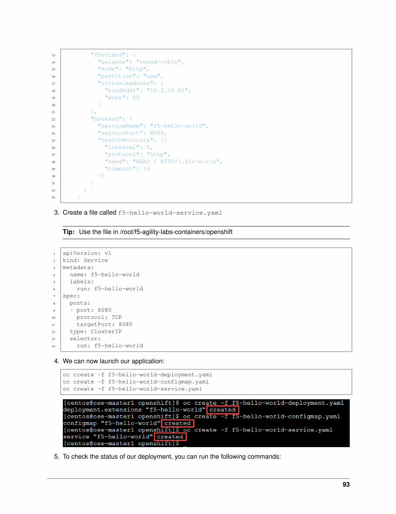
13 "frontend": {14 "balance": "round-robin",15 "mode": "http",16 "partition": "ose",17 "virtualAddress": {18 "bindAddr": "10.3.10.81",19 "port": 8020 }21 },22 "backend": {23 "serviceName": "f5-hello-world",24 "servicePort": 8080,25 "healthMonitors": [{26 "interval": 5,27 "protocol": "http",28 "send": "HEAD / HTTP/1.0\r\n\r\n",29 "timeout": 1630 }]31 }32 }33 }
3. Create a file called f5-hello-world-service.yaml
Tip: Use the file in /root/f5-agility-labs-containers/openshift
1 apiVersion: v12 kind: Service3 metadata:4 name: f5-hello-world5 labels:6 run: f5-hello-world7 spec:8 ports:9 - port: 8080
10 protocol: TCP11 targetPort: 808012 type: ClusterIP13 selector:14 run: f5-hello-world
4. We can now launch our application:
oc create -f f5-hello-world-deployment.yamloc create -f f5-hello-world-configmap.yamloc create -f f5-hello-world-service.yaml
5. To check the status of our deployment, you can run the following commands:
93
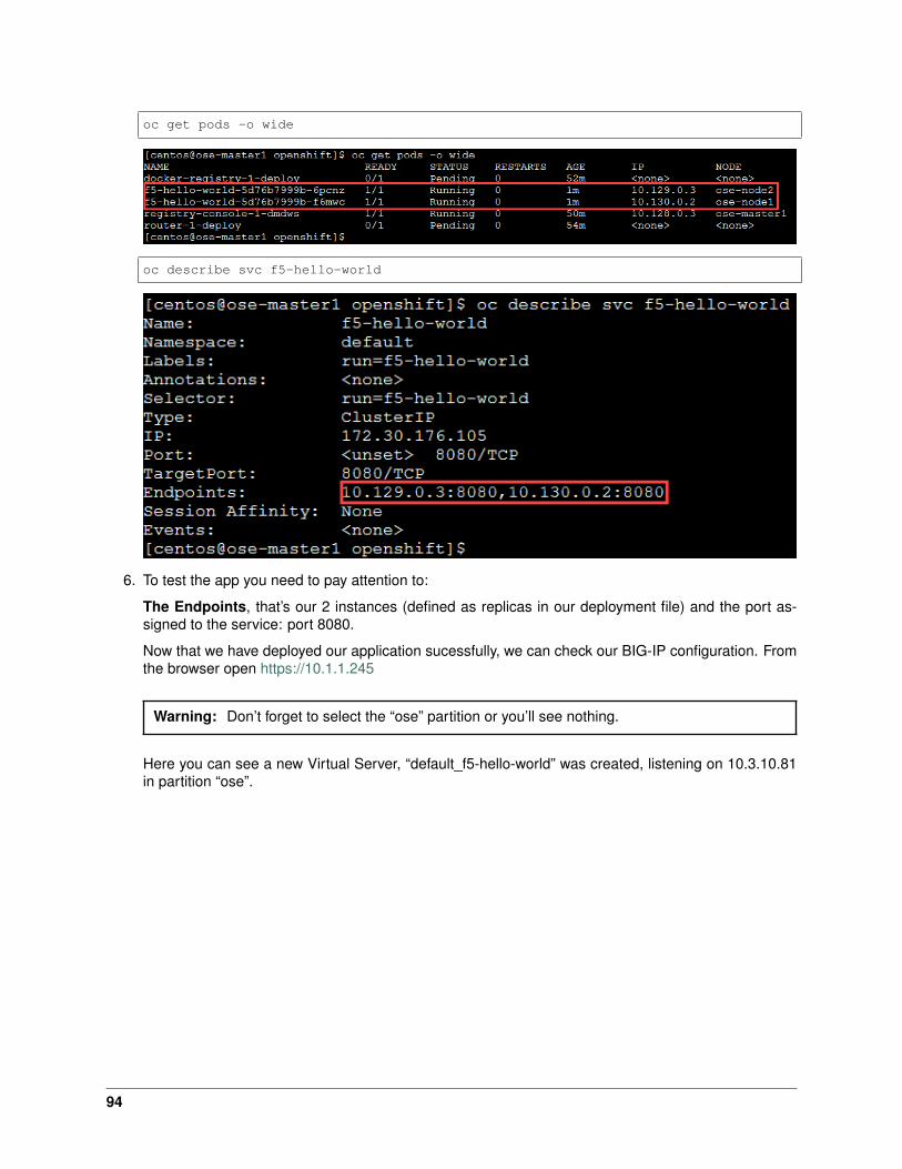
oc get pods -o wide
oc describe svc f5-hello-world
6. To test the app you need to pay attention to:
The Endpoints, that’s our 2 instances (defined as replicas in our deployment file) and the port as-signed to the service: port 8080.
Now that we have deployed our application sucessfully, we can check our BIG-IP configuration. Fromthe browser open https://10.1.1.245
Warning: Don’t forget to select the “ose” partition or you’ll see nothing.
Here you can see a new Virtual Server, “default_f5-hello-world” was created, listening on 10.3.10.81in partition “ose”.
94

Check the Pools to see a new pool and the associated pool members: Local Traffic –> Pools –>“cfgmap_default_f5-hello-world_f5-hello-world” –> Members
Note: You can see that the pool members IP addresses are assigned from the overlay network(ClusterIP mode)
7. Now access your application via the BIG-IP VIP: 10.3.10.81
95
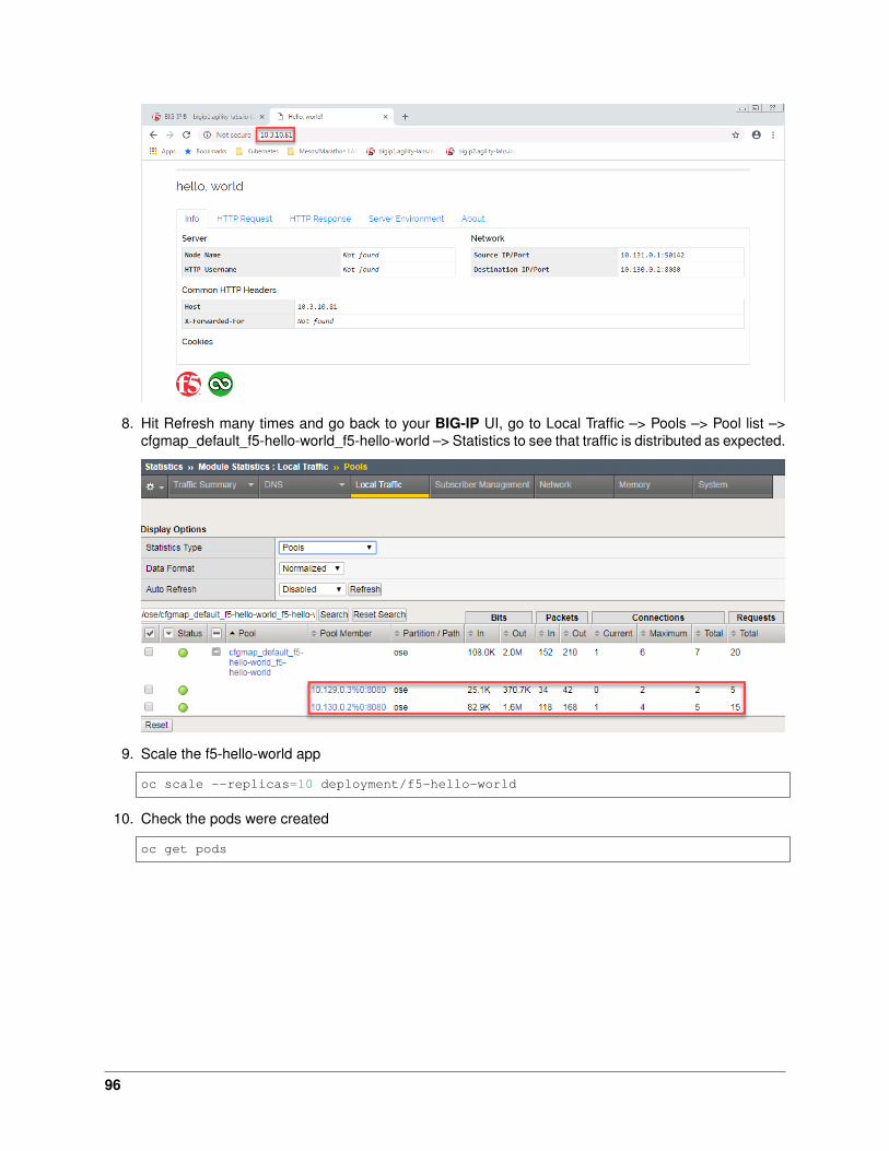
8. Hit Refresh many times and go back to your BIG-IP UI, go to Local Traffic –> Pools –> Pool list –>cfgmap_default_f5-hello-world_f5-hello-world –> Statistics to see that traffic is distributed as expected.
9. Scale the f5-hello-world app
oc scale --replicas=10 deployment/f5-hello-world
10. Check the pods were created
oc get pods
96

11. Check the pool was updated on big-ip
97
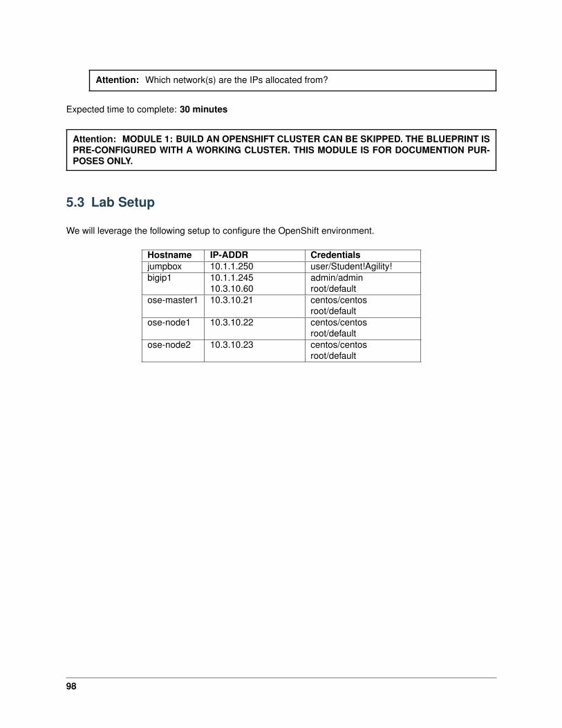
Attention: Which network(s) are the IPs allocated from?
Expected time to complete: 30 minutes
Attention: MODULE 1: BUILD AN OPENSHIFT CLUSTER CAN BE SKIPPED. THE BLUEPRINT ISPRE-CONFIGURED WITH A WORKING CLUSTER. THIS MODULE IS FOR DOCUMENTION PUR-POSES ONLY.
5.3 Lab Setup
We will leverage the following setup to configure the OpenShift environment.
Hostname IP-ADDR Credentialsjumpbox 10.1.1.250 user/Student!Agility!bigip1 10.1.1.245
10.3.10.60admin/adminroot/default
ose-master1 10.3.10.21 centos/centosroot/default
ose-node1 10.3.10.22 centos/centosroot/default
ose-node2 10.3.10.23 centos/centosroot/default
98

6Class 5: Advanced Labs for Red Hat OpenShift Container
Platform (OCP)
The purpose of this lab is to give you more visibility on
6.1 Module 1: Welcome to OpenShift!
This lab guide is the F5 Advanced Labs for Red Hat OpenShift Container Platform (OCP). This lab guideand blueprint was created using OCP version 3.7. This lab provides a quick tour of the console to help youget familiar with the user interface along with some key terminology we will use in subsequent lab content.
6.1.1 Key Terms
We will be using the following terms throughout the workshop labs so here are some basic definitions youshould be familiar with. And you’ll learn more terms along the way, but these are the basics to get youstarted.
• Container - Your software wrapped in a complete filesystem containing everything it needs to run
• Image - We are talking about Docker images; read-only and used to create containers
• Pod - One or more docker containers that run together
• Service - Provides a common DNS name to access a pod (or replicated set of pods)
• Project - A project is a group of services that are related logically (for this workshop we have setupyour account to have access to just a single project)
• Deployment - an update to your application triggered by a image change or config change
• Build - The process of turning your source code into a runnable image
• BuildConfig - configuration data that determines how to manage your build
• Route - a labeled and DNS mapped network path to a service from outside OpenShift
• Master - The foreman of the OpenShift architecture, the master schedules operations, watches forproblems, and orchestrates everything
• Node - Where the compute happens, your software is run on nodes
99
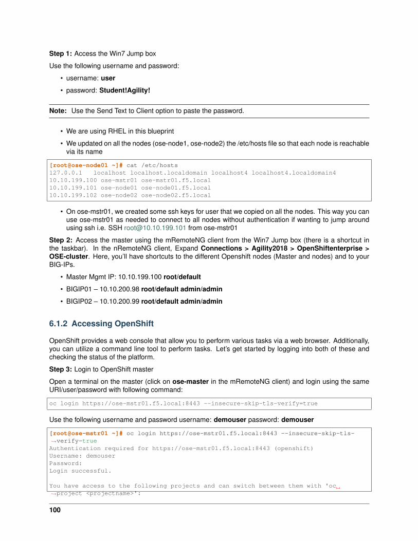
Step 1: Access the Win7 Jump box
Use the following username and password:
• username: user
• password: Student!Agility!
Note: Use the Send Text to Client option to paste the password.
• We are using RHEL in this blueprint
• We updated on all the nodes (ose-node1, ose-node2) the /etc/hosts file so that each node is reachablevia its name
[root@ose-node01 ~]# cat /etc/hosts127.0.0.1 localhost localhost.localdomain localhost4 localhost4.localdomain410.10.199.100 ose-mstr01 ose-mstr01.f5.local10.10.199.101 ose-node01 ose-node01.f5.local10.10.199.102 ose-node02 ose-node02.f5.local
• On ose-mstr01, we created some ssh keys for user that we copied on all the nodes. This way you canuse ose-mstr01 as needed to connect to all nodes without authentication if wanting to jump aroundusing ssh i.e. SSH [email protected] from ose-mstr01
Step 2: Access the master using the mRemoteNG client from the Win7 Jump box (there is a shortcut inthe taskbar). In the nRemoteNG client, Expand Connections > Agility2018 > OpenShiftenterprise >OSE-cluster. Here, you’ll have shortcuts to the different Openshift nodes (Master and nodes) and to yourBIG-IPs.
• Master Mgmt IP: 10.10.199.100 root/default
• BIGIP01 – 10.10.200.98 root/default admin/admin
• BIGIP02 – 10.10.200.99 root/default admin/admin
6.1.2 Accessing OpenShift
OpenShift provides a web console that allow you to perform various tasks via a web browser. Additionally,you can utilize a command line tool to perform tasks. Let’s get started by logging into both of these andchecking the status of the platform.
Step 3: Login to OpenShift master
Open a terminal on the master (click on ose-master in the mRemoteNG client) and login using the sameURI/user/password with following command:
oc login https://ose-mstr01.f5.local:8443 --insecure-skip-tls-verify=true
Use the following username and password username: demouser password: demouser
[root@ose-mstr01 ~]# oc login https://ose-mstr01.f5.local:8443 --insecure-skip-tls-→˓verify=trueAuthentication required for https://ose-mstr01.f5.local:8443 (openshift)Username: demouserPassword:Login successful.
You have access to the following projects and can switch between them with 'oc→˓project <projectname>':
100

defaultf5demoguestbookkube-publickube-service-catalog
* kube-systemloggingmanagement-infraopenshiftopenshift-infraopenshift-nodeopenshift-template-service-brokeryelb
Using project "kube-system".[root@ose-mstr01 ~]#
Step 4: Check the OpenShift status
The oc status command shows a high level overview of the project currently in use, with its componentsand their relationships, as shown in the following example:
[root@ose-mstr01 ~]# oc statusIn project kube-system on server https://ose-mstr01.f5.local:8443
You have no services, deployment configs, or build configs.Run 'oc new-app' to create an application.[root@ose-mstr01 ~]#
Step 5: Check the OpenShift nodes
You can manage nodes in your instance using the CLI. The CLI interacts with node objects that are repre-sentations of actual node hosts. The master uses the information from node objects to validate nodes withhealth checks.
To list all nodes that are known to the master:
[root@ose-mstr01 ~]# oc get nodesNAME STATUS AGE VERSIONose-mstr01.f5.local Ready,SchedulingDisabled 24d v1.7.6+a08f5eeb62ose-node01 Ready 24d v1.7.6+a08f5eeb62ose-node02 Ready 24d v1.7.6+a08f5eeb62[root@ose-mstr01 ~]#
If the node status shows NotReady or SchedulingDisabled contact the lab proctor. The node is notpassing the health checks performed from the master and Pods cannot be scheduled for placement on thenode.
Note: “SchedulingDisabled” for the Master is normal.
To get more detailed information about a specific node, including the reason for the current condition usethe oc describe node command. This does provide alot of very useful information and can assist withthroubleshooting issues.
[root@ose-mstr01 ~]# oc describe node ose-mstr01.f5.localName: ose-mstr01.f5.local
101
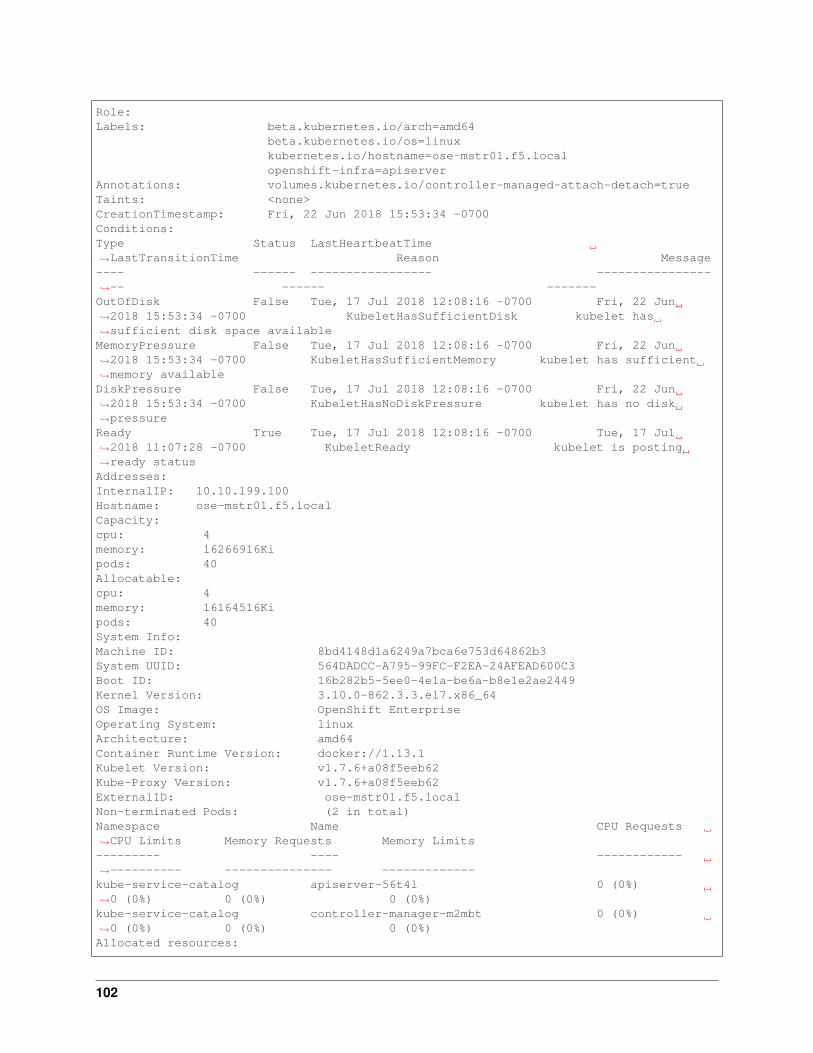
Role:Labels: beta.kubernetes.io/arch=amd64
beta.kubernetes.io/os=linuxkubernetes.io/hostname=ose-mstr01.f5.localopenshift-infra=apiserver
Annotations: volumes.kubernetes.io/controller-managed-attach-detach=trueTaints: <none>CreationTimestamp: Fri, 22 Jun 2018 15:53:34 -0700Conditions:Type Status LastHeartbeatTime→˓LastTransitionTime Reason Message---- ------ ----------------- ----------------→˓-- ------ -------OutOfDisk False Tue, 17 Jul 2018 12:08:16 -0700 Fri, 22 Jun→˓2018 15:53:34 -0700 KubeletHasSufficientDisk kubelet has→˓sufficient disk space availableMemoryPressure False Tue, 17 Jul 2018 12:08:16 -0700 Fri, 22 Jun→˓2018 15:53:34 -0700 KubeletHasSufficientMemory kubelet has sufficient→˓memory availableDiskPressure False Tue, 17 Jul 2018 12:08:16 -0700 Fri, 22 Jun→˓2018 15:53:34 -0700 KubeletHasNoDiskPressure kubelet has no disk→˓pressureReady True Tue, 17 Jul 2018 12:08:16 -0700 Tue, 17 Jul→˓2018 11:07:28 -0700 KubeletReady kubelet is posting→˓ready statusAddresses:InternalIP: 10.10.199.100Hostname: ose-mstr01.f5.localCapacity:cpu: 4memory: 16266916Kipods: 40Allocatable:cpu: 4memory: 16164516Kipods: 40System Info:Machine ID: 8bd4148d1a6249a7bca6e753d64862b3System UUID: 564DADCC-A795-99FC-F2EA-24AFEAD600C3Boot ID: 16b282b5-5ee0-4e1a-be6a-b8e1e2ae2449Kernel Version: 3.10.0-862.3.3.el7.x86_64OS Image: OpenShift EnterpriseOperating System: linuxArchitecture: amd64Container Runtime Version: docker://1.13.1Kubelet Version: v1.7.6+a08f5eeb62Kube-Proxy Version: v1.7.6+a08f5eeb62ExternalID: ose-mstr01.f5.localNon-terminated Pods: (2 in total)Namespace Name CPU Requests→˓CPU Limits Memory Requests Memory Limits--------- ---- ------------→˓---------- --------------- -------------kube-service-catalog apiserver-56t4l 0 (0%)→˓0 (0%) 0 (0%) 0 (0%)kube-service-catalog controller-manager-m2mbt 0 (0%)→˓0 (0%) 0 (0%) 0 (0%)Allocated resources:
102
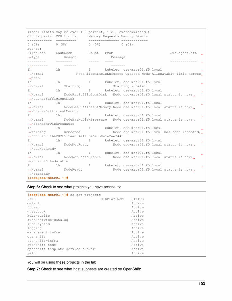
(Total limits may be over 100 percent, i.e., overcommitted.)CPU Requests CPU Limits Memory Requests Memory Limits------------ ---------- --------------- -------------0 (0%) 0 (0%) 0 (0%) 0 (0%)Events:FirstSeen LastSeen Count From SubObjectPath→˓Type Reason Message--------- -------- ----- ---- -------------→˓-------- ------ -------1h 1h 1 kubelet, ose-mstr01.f5.local→˓Normal NodeAllocatableEnforced Updated Node Allocatable limit across→˓pods1h 1h 1 kubelet, ose-mstr01.f5.local→˓Normal Starting Starting kubelet.1h 1h 1 kubelet, ose-mstr01.f5.local→˓Normal NodeHasSufficientDisk Node ose-mstr01.f5.local status is now:→˓NodeHasSufficientDisk1h 1h 1 kubelet, ose-mstr01.f5.local→˓Normal NodeHasSufficientMemory Node ose-mstr01.f5.local status is now:→˓NodeHasSufficientMemory1h 1h 1 kubelet, ose-mstr01.f5.local→˓Normal NodeHasNoDiskPressure Node ose-mstr01.f5.local status is now:→˓NodeHasNoDiskPressure1h 1h 1 kubelet, ose-mstr01.f5.local→˓Warning Rebooted Node ose-mstr01.f5.local has been rebooted,→˓boot id: 16b282b5-5ee0-4e1a-be6a-b8e1e2ae24491h 1h 1 kubelet, ose-mstr01.f5.local→˓Normal NodeNotReady Node ose-mstr01.f5.local status is now:→˓NodeNotReady1h 1h 1 kubelet, ose-mstr01.f5.local→˓Normal NodeNotSchedulable Node ose-mstr01.f5.local status is now:→˓NodeNotSchedulable1h 1h 1 kubelet, ose-mstr01.f5.local→˓Normal NodeReady Node ose-mstr01.f5.local status is now:→˓NodeReady[root@ose-mstr01 ~]#
Step 6: Check to see what projects you have access to:
[root@ose-mstr01 ~]# oc get projectsNAME DISPLAY NAME STATUSdefault Activef5demo Activeguestbook Activekube-public Activekube-service-catalog Activekube-system Activelogging Activemanagement-infra Activeopenshift Activeopenshift-infra Activeopenshift-node Activeopenshift-template-service-broker Activeyelb Active
You will be using these projects in the lab
Step 7: Check to see what host subnests are created on OpenShift:
103
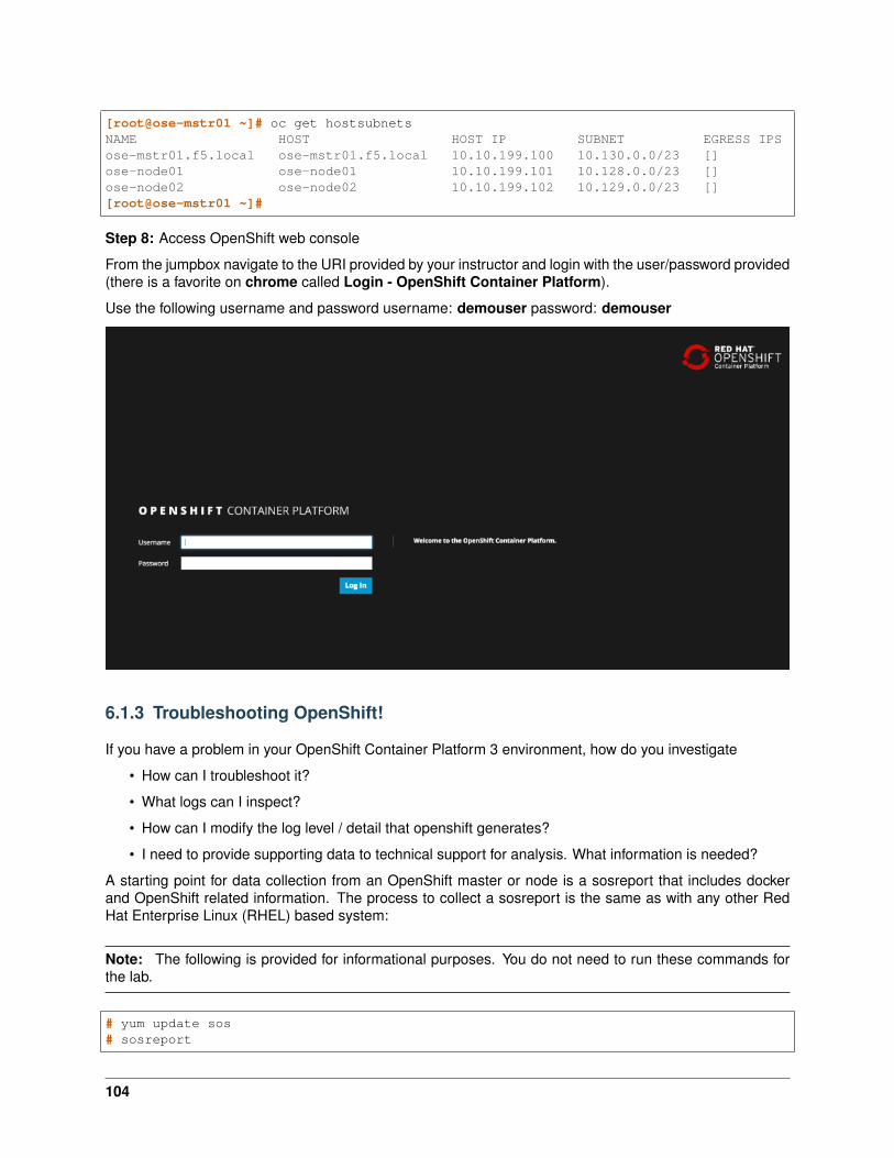
[root@ose-mstr01 ~]# oc get hostsubnetsNAME HOST HOST IP SUBNET EGRESS IPSose-mstr01.f5.local ose-mstr01.f5.local 10.10.199.100 10.130.0.0/23 []ose-node01 ose-node01 10.10.199.101 10.128.0.0/23 []ose-node02 ose-node02 10.10.199.102 10.129.0.0/23 [][root@ose-mstr01 ~]#
Step 8: Access OpenShift web console
From the jumpbox navigate to the URI provided by your instructor and login with the user/password provided(there is a favorite on chrome called Login - OpenShift Container Platform).
Use the following username and password username: demouser password: demouser
6.1.3 Troubleshooting OpenShift!
If you have a problem in your OpenShift Container Platform 3 environment, how do you investigate
• How can I troubleshoot it?
• What logs can I inspect?
• How can I modify the log level / detail that openshift generates?
• I need to provide supporting data to technical support for analysis. What information is needed?
A starting point for data collection from an OpenShift master or node is a sosreport that includes dockerand OpenShift related information. The process to collect a sosreport is the same as with any other RedHat Enterprise Linux (RHEL) based system:
Note: The following is provided for informational purposes. You do not need to run these commands forthe lab.
# yum update sos# sosreport
104
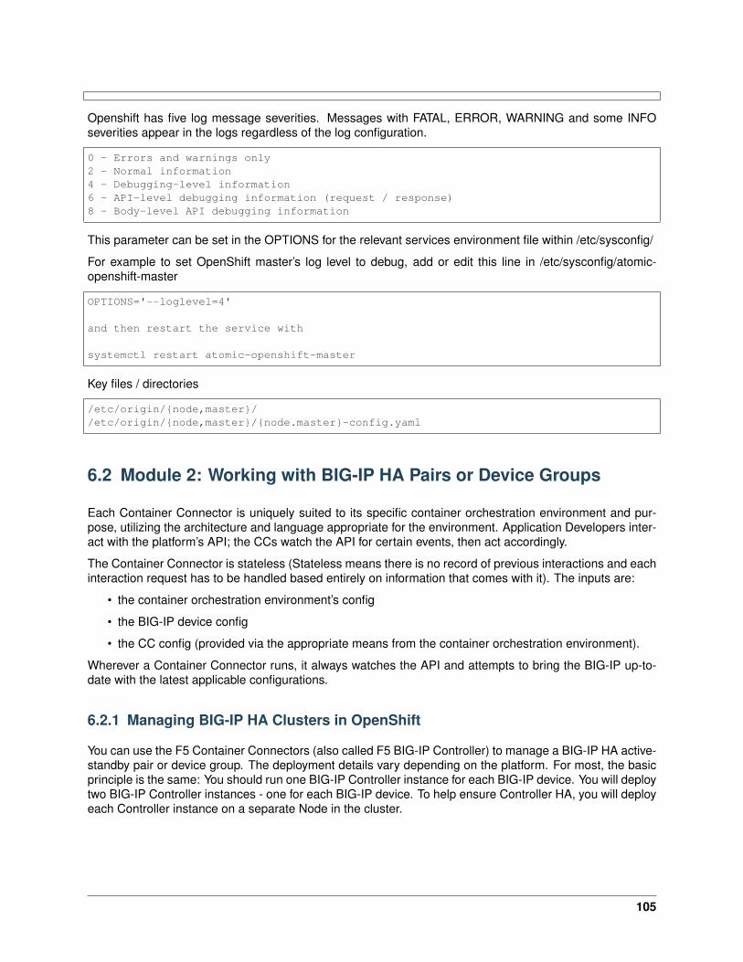
Openshift has five log message severities. Messages with FATAL, ERROR, WARNING and some INFOseverities appear in the logs regardless of the log configuration.
0 - Errors and warnings only2 - Normal information4 - Debugging-level information6 - API-level debugging information (request / response)8 - Body-level API debugging information
This parameter can be set in the OPTIONS for the relevant services environment file within /etc/sysconfig/
For example to set OpenShift master’s log level to debug, add or edit this line in /etc/sysconfig/atomic-openshift-master
OPTIONS='--loglevel=4'
and then restart the service with
systemctl restart atomic-openshift-master
Key files / directories
/etc/origin/{node,master}//etc/origin/{node,master}/{node.master}-config.yaml
6.2 Module 2: Working with BIG-IP HA Pairs or Device Groups
Each Container Connector is uniquely suited to its specific container orchestration environment and pur-pose, utilizing the architecture and language appropriate for the environment. Application Developers inter-act with the platform’s API; the CCs watch the API for certain events, then act accordingly.
The Container Connector is stateless (Stateless means there is no record of previous interactions and eachinteraction request has to be handled based entirely on information that comes with it). The inputs are:
• the container orchestration environment’s config
• the BIG-IP device config
• the CC config (provided via the appropriate means from the container orchestration environment).
Wherever a Container Connector runs, it always watches the API and attempts to bring the BIG-IP up-to-date with the latest applicable configurations.
6.2.1 Managing BIG-IP HA Clusters in OpenShift
You can use the F5 Container Connectors (also called F5 BIG-IP Controller) to manage a BIG-IP HA active-standby pair or device group. The deployment details vary depending on the platform. For most, the basicprinciple is the same: You should run one BIG-IP Controller instance for each BIG-IP device. You will deploytwo BIG-IP Controller instances - one for each BIG-IP device. To help ensure Controller HA, you will deployeach Controller instance on a separate Node in the cluster.
105
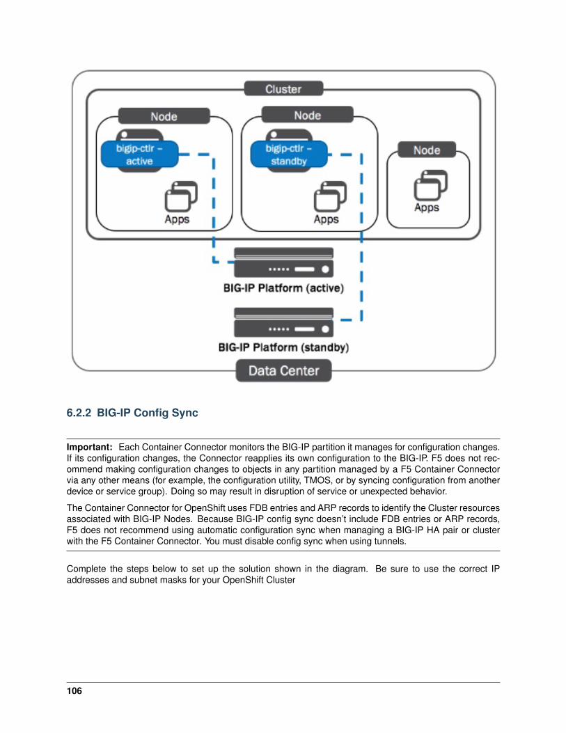
6.2.2 BIG-IP Config Sync
Important: Each Container Connector monitors the BIG-IP partition it manages for configuration changes.If its configuration changes, the Connector reapplies its own configuration to the BIG-IP. F5 does not rec-ommend making configuration changes to objects in any partition managed by a F5 Container Connectorvia any other means (for example, the configuration utility, TMOS, or by syncing configuration from anotherdevice or service group). Doing so may result in disruption of service or unexpected behavior.
The Container Connector for OpenShift uses FDB entries and ARP records to identify the Cluster resourcesassociated with BIG-IP Nodes. Because BIG-IP config sync doesn’t include FDB entries or ARP records,F5 does not recommend using automatic configuration sync when managing a BIG-IP HA pair or clusterwith the F5 Container Connector. You must disable config sync when using tunnels.
Complete the steps below to set up the solution shown in the diagram. Be sure to use the correct IPaddresses and subnet masks for your OpenShift Cluster
106
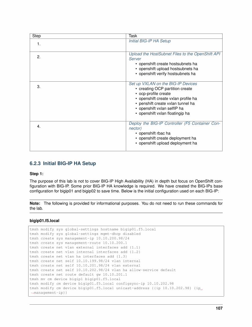
Step Task
1.Initial BIG-IP HA Setup
2.Upload the HostSubnet Files to the OpenShift APIServer
• openshift create hostsubnets ha• openshift upload hostsubnets ha• openshift verify hostsubnets ha
3.Set up VXLAN on the BIG-IP Devices
• creating OCP partition create• ocp-profile create• openshift create vxlan profile ha• penshift create vxlan tunnel ha• openshift vxlan selfIP ha• openshift vxlan floatingip ha
4.Deploy the BIG-IP Controller (F5 Container Con-nector)
• openshift rbac ha• openshift create deployment ha• openshift upload deployment ha
6.2.3 Initial BIG-IP HA Setup
Step 1:
The purpose of this lab is not to cover BIG-IP High Availability (HA) in depth but focus on OpenShift con-figuration with BIG-IP. Some prior BIG-IP HA knowledge is required. We have created the BIG-IPs baseconfiguration for bigip01 and bigip02 to save time. Below is the initial configuration used on each BIG-IP:
Note: The following is provided for informational purposes. You do not need to run these commands forthe lab.
bigip01.f5.local
tmsh modify sys global-settings hostname bigip01.f5.localtmsh modify sys global-settings mgmt-dhcp disabledtmsh create sys management-ip 10.10.200.98/24tmsh create sys management-route 10.10.200.1tmsh create net vlan external interfaces add {1.1}tmsh create net vlan internal interfaces add {1.2}tmsh create net vlan ha interfaces add {1.3}tmsh create net self 10.10.199.98/24 vlan internaltmsh create net self 10.10.201.98/24 vlan externaltmsh create net self 10.10.202.98/24 vlan ha allow-service defaulttmsh create net route default gw 10.10.201.1tmsh mv cm device bigip1 bigip01.f5.localtmsh modify cm device bigip01.f5.local configsync-ip 10.10.202.98tmsh modify cm device bigip01.f5.local unicast-address {{ip 10.10.202.98} {ip→˓management-ip}}
107

tmsh modify cm trust-domain ca-devices add {10.10.200.99} username admin password→˓admintmsh create cm device-group ocp-devicegroup devices add {bigip01.f5.local bigip02.f5.→˓local} type sync-failover auto-sync disabledtmsh run cm config-sync to-group ocp-devicegrouptmsh save sys config
bigip02.f5.local
tmsh modify sys global-settings hostname bigip02.f5.localtmsh modify sys global-settings mgmt-dhcp disabledtmsh create sys management-ip 10.10.200.99/24tmsh create sys management-route 10.10.200.1tmsh create net vlan external interfaces add {1.1}tmsh create net vlan internal interfaces add {1.2}tmsh create net vlan ha interfaces add {1.3}tmsh create net self 10.10.199.99/24 vlan internaltmsh create net self 10.10.201.99/24 vlan externaltmsh create net self 10.10.202.99/24 vlan ha allow-service defaulttmsh create net route default gw 10.10.201.1tmsh modify sys global-settings gui-setup disabledtmsh mv cm device bigip1 bigip02.f5.localtmsh modify cm device bigip02.f5.local configsync-ip 10.10.202.99tmsh modify cm device bigip02.f5.local unicast-address {{ip 10.10.202.99} {ip→˓management-ip}}tmsh save sys config
Tip: Before adding the BIG-IP devices to OpenShift make sure your High Availability (HA) device trustgroup, license, selfIP, vlans are configured correctly.
Note: You have shortcuts to connect to your BIG-IPs in Chrome. Login: admin, Password: admin
Validate that SDN services license is active
Attention: In your lab environment the BIG-IP VE LAB license includes the SDN license. The followingis provided as a reference of what you may see in a production license. The SDN license is also includedin the -V16 version of the BIG-IP VE license.
108
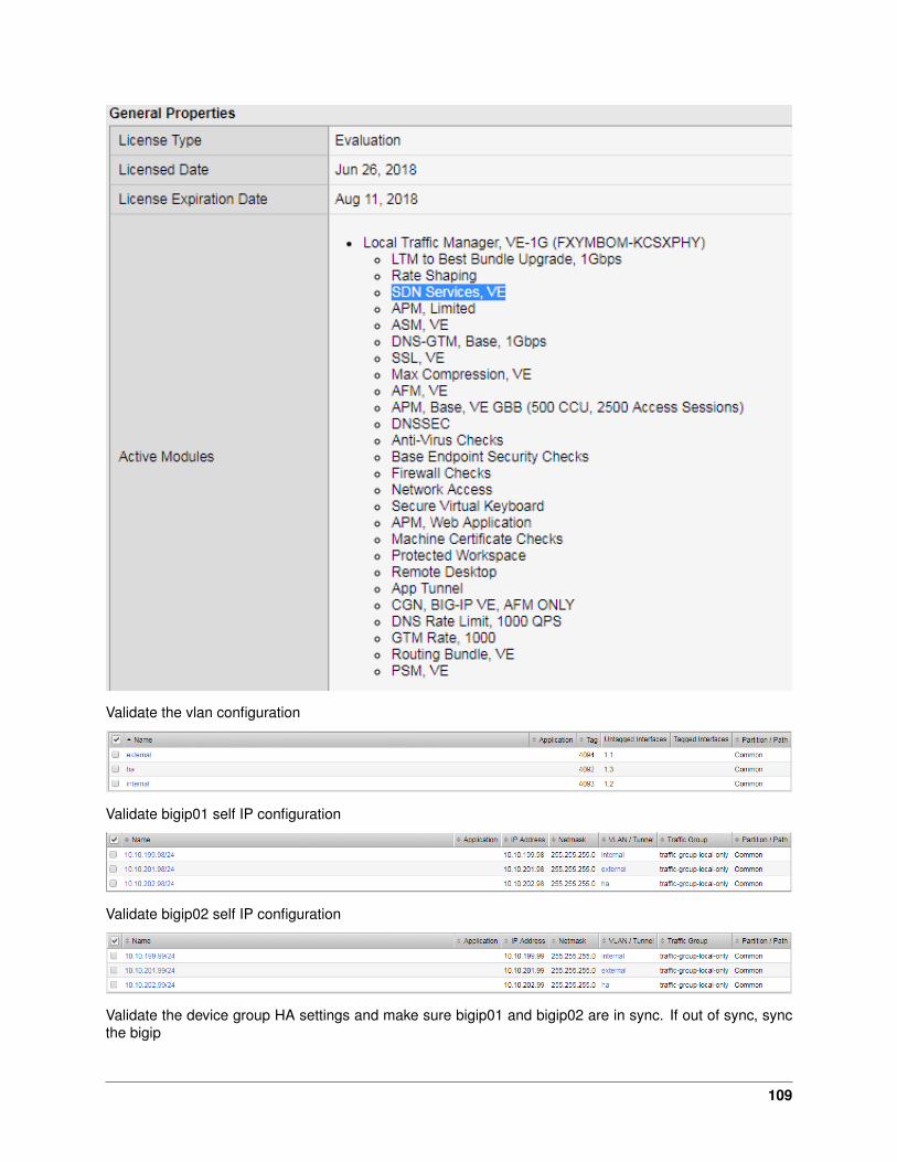
Validate the vlan configuration
Validate bigip01 self IP configuration
Validate bigip02 self IP configuration
Validate the device group HA settings and make sure bigip01 and bigip02 are in sync. If out of sync, syncthe bigip
109
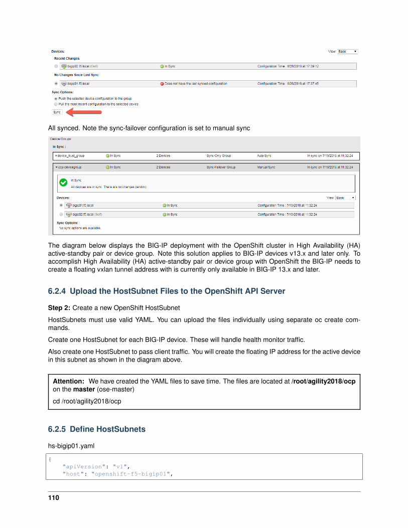
All synced. Note the sync-failover configuration is set to manual sync
The diagram below displays the BIG-IP deployment with the OpenShift cluster in High Availability (HA)active-standby pair or device group. Note this solution applies to BIG-IP devices v13.x and later only. Toaccomplish High Availability (HA) active-standby pair or device group with OpenShift the BIG-IP needs tocreate a floating vxlan tunnel address with is currently only available in BIG-IP 13.x and later.
6.2.4 Upload the HostSubnet Files to the OpenShift API Server
Step 2: Create a new OpenShift HostSubnet
HostSubnets must use valid YAML. You can upload the files individually using separate oc create com-mands.
Create one HostSubnet for each BIG-IP device. These will handle health monitor traffic.
Also create one HostSubnet to pass client traffic. You will create the floating IP address for the active devicein this subnet as shown in the diagram above.
Attention: We have created the YAML files to save time. The files are located at /root/agility2018/ocpon the master (ose-master)
cd /root/agility2018/ocp
6.2.5 Define HostSubnets
hs-bigip01.yaml
{"apiVersion": "v1","host": "openshift-f5-bigip01",
110

"hostIP": "10.10.199.98","kind": "HostSubnet","metadata": {
"name": "openshift-f5-bigip01"},"subnet": "10.131.0.0/23"
}
hs-bigip02.yaml
{"apiVersion": "v1","host": "openshift-f5-bigip02","hostIP": "10.10.199.99","kind": "HostSubnet","metadata": {
"name": "openshift-f5-bigip02"},"subnet": "10.131.2.0/23"
}
hs-bigip-float.yaml
{"apiVersion": "v1","host": "openshift-f5-bigip-float","hostIP": "10.10.199.200","kind": "HostSubnet","metadata": {
"name": "openshift-f5-bigip-float"},"subnet": "10.131.4.0/23"
}
Create the HostSubnet files to the OpenShift API server. Run the following commands from the master
oc create -f hs-bigip01.yamloc create -f hs-bigip02.yamloc create -f hs-bigip-float.yaml
Verify creation of the HostSubnets:
[root@ose-mstr01 ocp]# oc get hostsubnetNAME HOST HOST IP SUBNET→˓EGRESS IPSopenshift-f5-bigip-float openshift-f5-bigip-float 10.10.199.200 10.131.4.0/23→˓[]openshift-f5-bigip01 openshift-f5-bigip01 10.10.199.98 10.131.0.0/23→˓[]openshift-f5-bigip02 openshift-f5-bigip02 10.10.199.99 10.131.2.0/23→˓[]ose-mstr01.f5.local ose-mstr01.f5.local 10.10.199.100 10.130.0.0/23→˓[]ose-node01 ose-node01 10.10.199.101 10.128.0.0/23→˓[]ose-node02 ose-node02 10.10.199.102 10.129.0.0/23→˓[][root@ose-mstr01 ocp]#
111
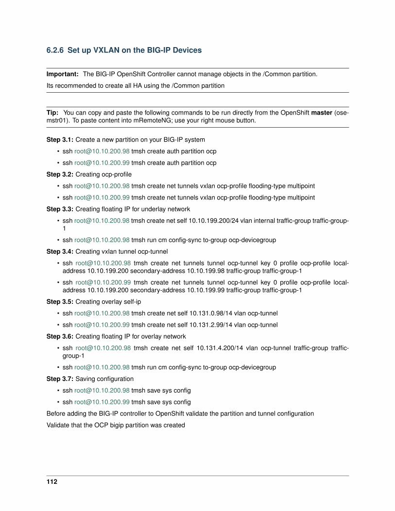
6.2.6 Set up VXLAN on the BIG-IP Devices
Important: The BIG-IP OpenShift Controller cannot manage objects in the /Common partition.
Its recommended to create all HA using the /Common partition
Tip: You can copy and paste the following commands to be run directly from the OpenShift master (ose-mstr01). To paste content into mRemoteNG; use your right mouse button.
Step 3.1: Create a new partition on your BIG-IP system
• ssh [email protected] tmsh create auth partition ocp
• ssh [email protected] tmsh create auth partition ocp
Step 3.2: Creating ocp-profile
• ssh [email protected] tmsh create net tunnels vxlan ocp-profile flooding-type multipoint
• ssh [email protected] tmsh create net tunnels vxlan ocp-profile flooding-type multipoint
Step 3.3: Creating floating IP for underlay network
• ssh [email protected] tmsh create net self 10.10.199.200/24 vlan internal traffic-group traffic-group-1
• ssh [email protected] tmsh run cm config-sync to-group ocp-devicegroup
Step 3.4: Creating vxlan tunnel ocp-tunnel
• ssh [email protected] tmsh create net tunnels tunnel ocp-tunnel key 0 profile ocp-profile local-address 10.10.199.200 secondary-address 10.10.199.98 traffic-group traffic-group-1
• ssh [email protected] tmsh create net tunnels tunnel ocp-tunnel key 0 profile ocp-profile local-address 10.10.199.200 secondary-address 10.10.199.99 traffic-group traffic-group-1
Step 3.5: Creating overlay self-ip
• ssh [email protected] tmsh create net self 10.131.0.98/14 vlan ocp-tunnel
• ssh [email protected] tmsh create net self 10.131.2.99/14 vlan ocp-tunnel
Step 3.6: Creating floating IP for overlay network
• ssh [email protected] tmsh create net self 10.131.4.200/14 vlan ocp-tunnel traffic-group traffic-group-1
• ssh [email protected] tmsh run cm config-sync to-group ocp-devicegroup
Step 3.7: Saving configuration
• ssh [email protected] tmsh save sys config
• ssh [email protected] tmsh save sys config
Before adding the BIG-IP controller to OpenShift validate the partition and tunnel configuration
Validate that the OCP bigip partition was created
112
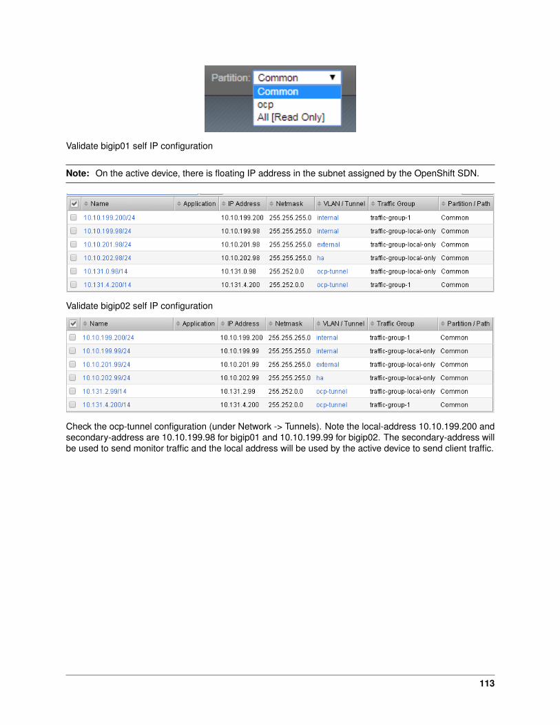
Validate bigip01 self IP configuration
Note: On the active device, there is floating IP address in the subnet assigned by the OpenShift SDN.
Validate bigip02 self IP configuration
Check the ocp-tunnel configuration (under Network -> Tunnels). Note the local-address 10.10.199.200 andsecondary-address are 10.10.199.98 for bigip01 and 10.10.199.99 for bigip02. The secondary-address willbe used to send monitor traffic and the local address will be used by the active device to send client traffic.
113
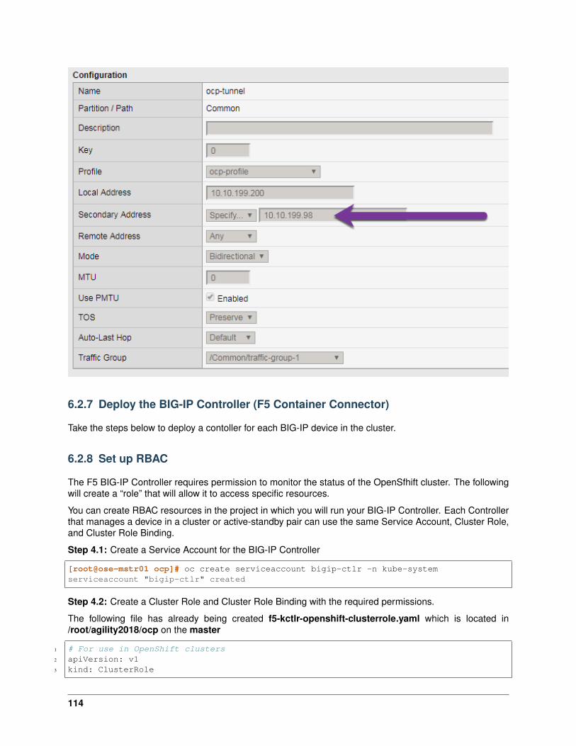
6.2.7 Deploy the BIG-IP Controller (F5 Container Connector)
Take the steps below to deploy a contoller for each BIG-IP device in the cluster.
6.2.8 Set up RBAC
The F5 BIG-IP Controller requires permission to monitor the status of the OpenSfhift cluster. The followingwill create a “role” that will allow it to access specific resources.
You can create RBAC resources in the project in which you will run your BIG-IP Controller. Each Controllerthat manages a device in a cluster or active-standby pair can use the same Service Account, Cluster Role,and Cluster Role Binding.
Step 4.1: Create a Service Account for the BIG-IP Controller
[root@ose-mstr01 ocp]# oc create serviceaccount bigip-ctlr -n kube-systemserviceaccount "bigip-ctlr" created
Step 4.2: Create a Cluster Role and Cluster Role Binding with the required permissions.
The following file has already being created f5-kctlr-openshift-clusterrole.yaml which is located in/root/agility2018/ocp on the master
1 # For use in OpenShift clusters2 apiVersion: v13 kind: ClusterRole
114

4 metadata:5 annotations:6 authorization.openshift.io/system-only: "true"7 name: system:bigip-ctlr8 rules:9 - apiGroups: ["", "extensions"]
10 resources: ["nodes", "services", "endpoints", "namespaces", "ingresses", "routes" ]11 verbs: ["get", "list", "watch"]12 - apiGroups: ["", "extensions"]13 resources: ["configmaps", "events", "ingresses/status"]14 verbs: ["get", "list", "watch", "update", "create", "patch" ]15 - apiGroups: ["", "extensions"]16 resources: ["secrets"]17 resourceNames: ["<secret-containing-bigip-login>"]18 verbs: ["get", "list", "watch"]19
20 ---21
22 apiVersion: v123 kind: ClusterRoleBinding24 metadata:25 name: bigip-ctlr-role26 userNames:27 - system:serviceaccount:kube-system:bigip-ctlr28 subjects:29 - kind: ServiceAccount30 name: bigip-ctlr31 roleRef:32 name: system:bigip-ctlr
[root@ose-mstr01 ocp]# oc create -f f5-kctlr-openshift-clusterrole.yamlclusterrole "system:bigip-ctlr" createdclusterrolebinding "bigip-ctlr-role" created
6.2.9 Create Deployments
Step 4.3: Deploy the BIG-IP Controller
Create an OpenShift Deployment for each Controller (one per BIG-IP device). You need to deploy a con-troller for both f5-bigip-node01 and f5-bigip-node02
• Provide a unique metadata.name for each Controller.
• Provide a unique –bigip-url in each Deployment (each Controller manages a separate BIG-IP device).
• Use the same –bigip-partition in all Deployments.
bigip01-cc.yaml
1 apiVersion: extensions/v1beta12 kind: Deployment3 metadata:4 name: bigip01-ctlr5 namespace: kube-system6 spec:7 replicas: 18 template:9 metadata:
115

10 name: k8s-bigip-ctlr111 labels:12 app: k8s-bigip-ctlr113 spec:14 serviceAccountName: bigip-ctlr15 containers:16 - name: k8s-bigip-ctlr17 image: "f5networks/k8s-bigip-ctlr:latest"18 command: ["/app/bin/k8s-bigip-ctlr"]19 args: [20 "--credentials-directory=/tmp/creds",21 "--bigip-url=10.10.200.98",22 "--bigip-partition=ocp",23 "--pool-member-type=cluster",24 "--manage-routes=true",25 "--node-poll-interval=5",26 "--verify-interval=5",27 "--namespace=demoproj",28 "--namespace=yelb",29 "--namespace=guestbook",30 "--namespace=f5demo",31 "--route-vserver-addr=10.10.201.120",32 "--route-http-vserver=ocp-vserver",33 "--route-https-vserver=ocp-https-vserver",34 "--openshift-sdn-name=/Common/ocp-tunnel"35 ]36 volumeMounts:37 - name: bigip-creds38 mountPath: "/tmp/creds"39 readOnly: true40 volumes:41 - name: bigip-creds42 secret:43 secretName: bigip-login44 imagePullSecrets:45 - name: f5-docker-images
bigip02-cc.yaml
1 apiVersion: extensions/v1beta12 kind: Deployment3 metadata:4 name: bigip02-ctlr5 namespace: kube-system6 spec:7 replicas: 18 template:9 metadata:
10 name: k8s-bigip-ctlr111 labels:12 app: k8s-bigip-ctlr113 spec:14 serviceAccountName: bigip-ctlr15 containers:16 - name: k8s-bigip-ctlr17 image: "f5networks/k8s-bigip-ctlr:latest"18 command: ["/app/bin/k8s-bigip-ctlr"]19 args: [
116
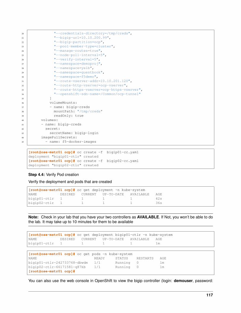
20 "--credentials-directory=/tmp/creds",21 "--bigip-url=10.10.200.99",22 "--bigip-partition=ocp",23 "--pool-member-type=cluster",24 "--manage-routes=true",25 "--node-poll-interval=5",26 "--verify-interval=5",27 "--namespace=demoproj",28 "--namespace=yelb",29 "--namespace=guestbook",30 "--namespace=f5demo",31 "--route-vserver-addr=10.10.201.120",32 "--route-http-vserver=ocp-vserver",33 "--route-https-vserver=ocp-https-vserver",34 "--openshift-sdn-name=/Common/ocp-tunnel"35 ]36 volumeMounts:37 - name: bigip-creds38 mountPath: "/tmp/creds"39 readOnly: true40 volumes:41 - name: bigip-creds42 secret:43 secretName: bigip-login44 imagePullSecrets:45 - name: f5-docker-images
[root@ose-mstr01 ocp]# oc create -f bigip01-cc.yamldeployment "bigip01-ctlr" created[root@ose-mstr01 ocp]# oc create -f bigip02-cc.yamldeployment "bigip02-ctlr" created
Step 4.4: Verify Pod creation
Verify the deployment and pods that are created
[root@ose-mstr01 ocp]# oc get deployment -n kube-systemNAME DESIRED CURRENT UP-TO-DATE AVAILABLE AGEbigip01-ctlr 1 1 1 1 42sbigip02-ctlr 1 1 1 1 36s
Note: Check in your lab that you have your two controllers as AVAILABLE. If Not, you won’t be able to dothe lab. It may take up to 10 minutes for them to be available
[root@ose-mstr01 ocp]# oc get deployment bigip01-ctlr -n kube-systemNAME DESIRED CURRENT UP-TO-DATE AVAILABLE AGEbigip01-ctlr 1 1 1 1 1m
[root@ose-mstr01 ocp]# oc get pods -n kube-systemNAME READY STATUS RESTARTS AGEbigip01-ctlr-242733768-dbwdm 1/1 Running 0 1mbigip02-ctlr-66171581-q87kb 1/1 Running 0 1m[root@ose-mstr01 ocp]#
You can also use the web console in OpenShift to view the bigip controller (login: demouser, password:
117

demouser). Go the kube-system project
6.2.10 Upload the Deployments
Step 4.5: Upload the Deployments to the OpenShift API server. Use the pool-only configmap to configura-tion project namespace: f5demo on the bigip
pool-only.yaml
1 kind: ConfigMap2 apiVersion: v13 metadata:4 # name of the resource to create on the BIG-IP5 name: k8s.poolonly6 # the namespace to create the object in7 # As of v1.1, the k8s-bigip-ctlr watches all namespaces by default8 # If the k8s-bigip-ctlr is watching a specific namespace(s),9 # this setting must match the namespace of the Service you want to proxy
10 # -AND- the namespace(s) the k8s-bigip-ctlr watches11 namespace: f5demo12 labels:13 # the type of resource you want to create on the BIG-IP14 f5type: virtual-server15 data:16 schema: "f5schemadb://bigip-virtual-server_v0.1.7.json"17 data: |18 {19 "virtualServer": {20 "backend": {21 "servicePort": 8080,22 "serviceName": "f5demo",
118
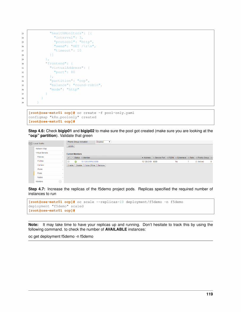
23 "healthMonitors": [{24 "interval": 3,25 "protocol": "http",26 "send": "GET /\r\n",27 "timeout": 1028 }]29 },30 "frontend": {31 "virtualAddress": {32 "port": 8033 },34 "partition": "ocp",35 "balance": "round-robin",36 "mode": "http"37 }38 }39 }
[root@ose-mstr01 ocp]# oc create -f pool-only.yamlconfigmap "k8s.poolonly" created[root@ose-mstr01 ocp]#
Step 4.6: Check bigip01 and bigip02 to make sure the pool got created (make sure you are looking at the“ocp” partition). Validate that green
Step 4.7: Increase the replicas of the f5demo project pods. Replicas specified the required number ofinstances to run
[root@ose-mstr01 ocp]# oc scale --replicas=10 deployment/f5demo -n f5demodeployment "f5demo" scaled[root@ose-mstr01 ocp]#
Note: It may take time to have your replicas up and running. Don’t hesitate to track this by using thefollowing command. to check the number of AVAILABLE instances:
oc get deployment f5demo -n f5demo
119
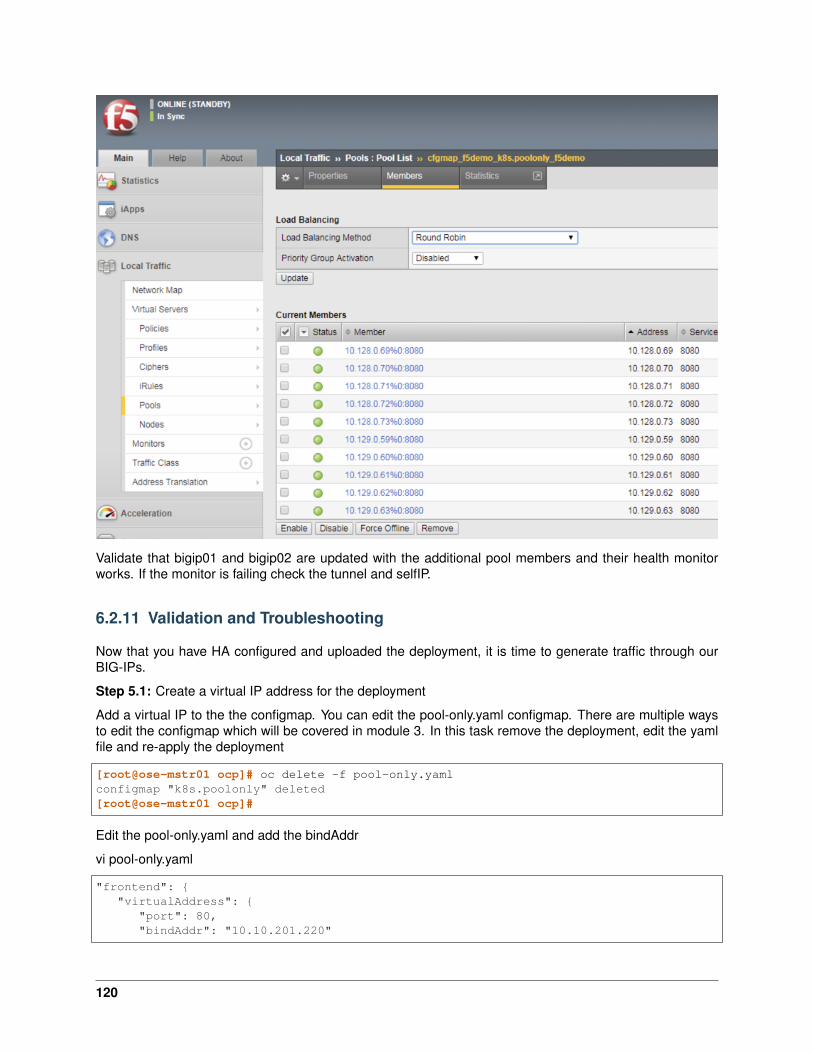
Validate that bigip01 and bigip02 are updated with the additional pool members and their health monitorworks. If the monitor is failing check the tunnel and selfIP.
6.2.11 Validation and Troubleshooting
Now that you have HA configured and uploaded the deployment, it is time to generate traffic through ourBIG-IPs.
Step 5.1: Create a virtual IP address for the deployment
Add a virtual IP to the the configmap. You can edit the pool-only.yaml configmap. There are multiple waysto edit the configmap which will be covered in module 3. In this task remove the deployment, edit the yamlfile and re-apply the deployment
[root@ose-mstr01 ocp]# oc delete -f pool-only.yamlconfigmap "k8s.poolonly" deleted[root@ose-mstr01 ocp]#
Edit the pool-only.yaml and add the bindAddr
vi pool-only.yaml
"frontend": {"virtualAddress": {
"port": 80,"bindAddr": "10.10.201.220"
120
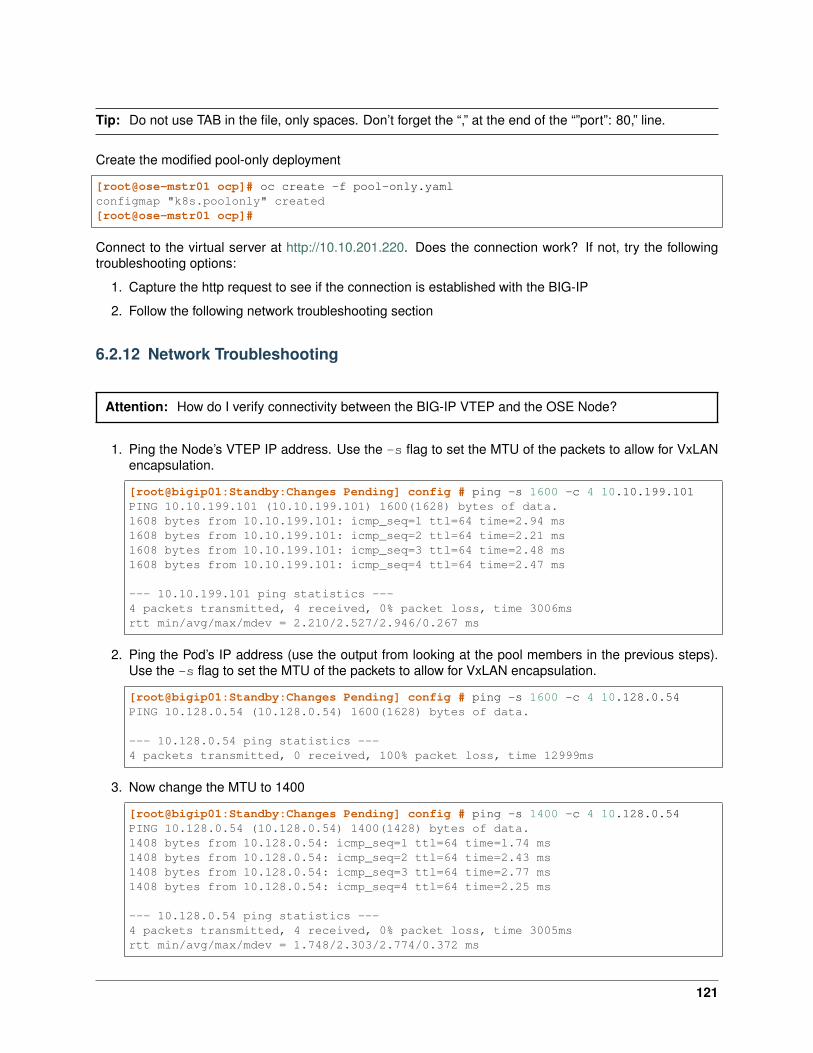
Tip: Do not use TAB in the file, only spaces. Don’t forget the “,” at the end of the “”port”: 80,” line.
Create the modified pool-only deployment
[root@ose-mstr01 ocp]# oc create -f pool-only.yamlconfigmap "k8s.poolonly" created[root@ose-mstr01 ocp]#
Connect to the virtual server at http://10.10.201.220. Does the connection work? If not, try the followingtroubleshooting options:
1. Capture the http request to see if the connection is established with the BIG-IP
2. Follow the following network troubleshooting section
6.2.12 Network Troubleshooting
Attention: How do I verify connectivity between the BIG-IP VTEP and the OSE Node?
1. Ping the Node’s VTEP IP address. Use the -s flag to set the MTU of the packets to allow for VxLANencapsulation.
[root@bigip01:Standby:Changes Pending] config # ping -s 1600 -c 4 10.10.199.101PING 10.10.199.101 (10.10.199.101) 1600(1628) bytes of data.1608 bytes from 10.10.199.101: icmp_seq=1 ttl=64 time=2.94 ms1608 bytes from 10.10.199.101: icmp_seq=2 ttl=64 time=2.21 ms1608 bytes from 10.10.199.101: icmp_seq=3 ttl=64 time=2.48 ms1608 bytes from 10.10.199.101: icmp_seq=4 ttl=64 time=2.47 ms
--- 10.10.199.101 ping statistics ---4 packets transmitted, 4 received, 0% packet loss, time 3006msrtt min/avg/max/mdev = 2.210/2.527/2.946/0.267 ms
2. Ping the Pod’s IP address (use the output from looking at the pool members in the previous steps).Use the -s flag to set the MTU of the packets to allow for VxLAN encapsulation.
[root@bigip01:Standby:Changes Pending] config # ping -s 1600 -c 4 10.128.0.54PING 10.128.0.54 (10.128.0.54) 1600(1628) bytes of data.
--- 10.128.0.54 ping statistics ---4 packets transmitted, 0 received, 100% packet loss, time 12999ms
3. Now change the MTU to 1400
[root@bigip01:Standby:Changes Pending] config # ping -s 1400 -c 4 10.128.0.54PING 10.128.0.54 (10.128.0.54) 1400(1428) bytes of data.1408 bytes from 10.128.0.54: icmp_seq=1 ttl=64 time=1.74 ms1408 bytes from 10.128.0.54: icmp_seq=2 ttl=64 time=2.43 ms1408 bytes from 10.128.0.54: icmp_seq=3 ttl=64 time=2.77 ms1408 bytes from 10.128.0.54: icmp_seq=4 ttl=64 time=2.25 ms
--- 10.128.0.54 ping statistics ---4 packets transmitted, 4 received, 0% packet loss, time 3005msrtt min/avg/max/mdev = 1.748/2.303/2.774/0.372 ms
121
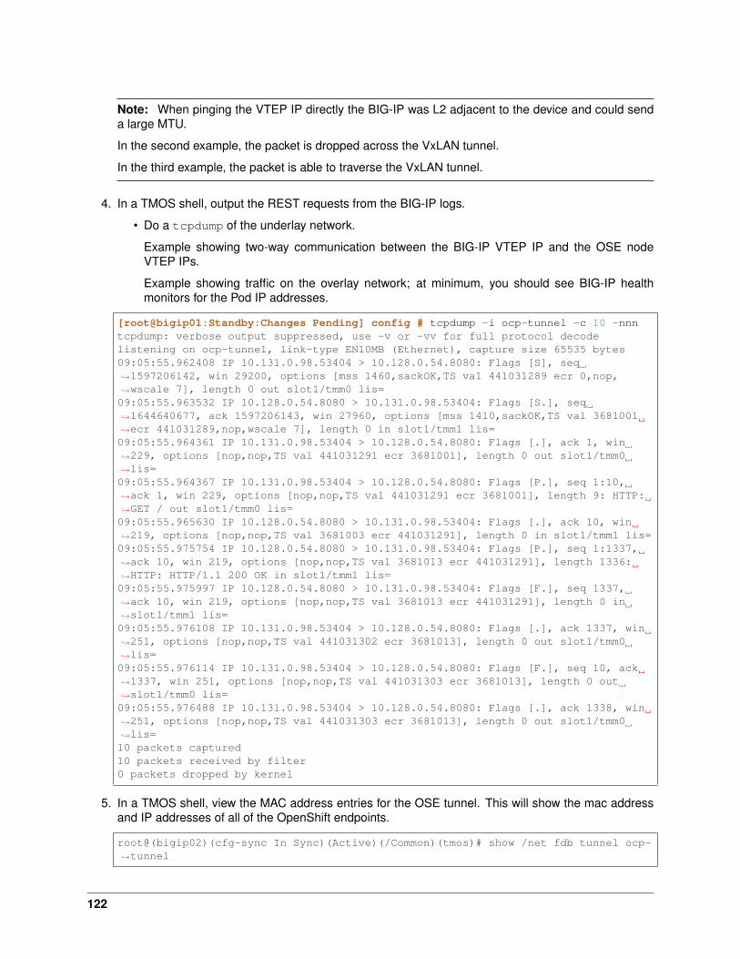
Note: When pinging the VTEP IP directly the BIG-IP was L2 adjacent to the device and could senda large MTU.
In the second example, the packet is dropped across the VxLAN tunnel.
In the third example, the packet is able to traverse the VxLAN tunnel.
4. In a TMOS shell, output the REST requests from the BIG-IP logs.
• Do a tcpdump of the underlay network.
Example showing two-way communication between the BIG-IP VTEP IP and the OSE nodeVTEP IPs.
Example showing traffic on the overlay network; at minimum, you should see BIG-IP healthmonitors for the Pod IP addresses.
[root@bigip01:Standby:Changes Pending] config # tcpdump -i ocp-tunnel -c 10 -nnntcpdump: verbose output suppressed, use -v or -vv for full protocol decodelistening on ocp-tunnel, link-type EN10MB (Ethernet), capture size 65535 bytes09:05:55.962408 IP 10.131.0.98.53404 > 10.128.0.54.8080: Flags [S], seq→˓1597206142, win 29200, options [mss 1460,sackOK,TS val 441031289 ecr 0,nop,→˓wscale 7], length 0 out slot1/tmm0 lis=09:05:55.963532 IP 10.128.0.54.8080 > 10.131.0.98.53404: Flags [S.], seq→˓1644640677, ack 1597206143, win 27960, options [mss 1410,sackOK,TS val 3681001→˓ecr 441031289,nop,wscale 7], length 0 in slot1/tmm1 lis=09:05:55.964361 IP 10.131.0.98.53404 > 10.128.0.54.8080: Flags [.], ack 1, win→˓229, options [nop,nop,TS val 441031291 ecr 3681001], length 0 out slot1/tmm0→˓lis=09:05:55.964367 IP 10.131.0.98.53404 > 10.128.0.54.8080: Flags [P.], seq 1:10,→˓ack 1, win 229, options [nop,nop,TS val 441031291 ecr 3681001], length 9: HTTP:→˓GET / out slot1/tmm0 lis=09:05:55.965630 IP 10.128.0.54.8080 > 10.131.0.98.53404: Flags [.], ack 10, win→˓219, options [nop,nop,TS val 3681003 ecr 441031291], length 0 in slot1/tmm1 lis=09:05:55.975754 IP 10.128.0.54.8080 > 10.131.0.98.53404: Flags [P.], seq 1:1337,→˓ack 10, win 219, options [nop,nop,TS val 3681013 ecr 441031291], length 1336:→˓HTTP: HTTP/1.1 200 OK in slot1/tmm1 lis=09:05:55.975997 IP 10.128.0.54.8080 > 10.131.0.98.53404: Flags [F.], seq 1337,→˓ack 10, win 219, options [nop,nop,TS val 3681013 ecr 441031291], length 0 in→˓slot1/tmm1 lis=09:05:55.976108 IP 10.131.0.98.53404 > 10.128.0.54.8080: Flags [.], ack 1337, win→˓251, options [nop,nop,TS val 441031302 ecr 3681013], length 0 out slot1/tmm0→˓lis=09:05:55.976114 IP 10.131.0.98.53404 > 10.128.0.54.8080: Flags [F.], seq 10, ack→˓1337, win 251, options [nop,nop,TS val 441031303 ecr 3681013], length 0 out→˓slot1/tmm0 lis=09:05:55.976488 IP 10.131.0.98.53404 > 10.128.0.54.8080: Flags [.], ack 1338, win→˓251, options [nop,nop,TS val 441031303 ecr 3681013], length 0 out slot1/tmm0→˓lis=10 packets captured10 packets received by filter0 packets dropped by kernel
5. In a TMOS shell, view the MAC address entries for the OSE tunnel. This will show the mac addressand IP addresses of all of the OpenShift endpoints.
root@(bigip02)(cfg-sync In Sync)(Active)(/Common)(tmos)# show /net fdb tunnel ocp-→˓tunnel
122
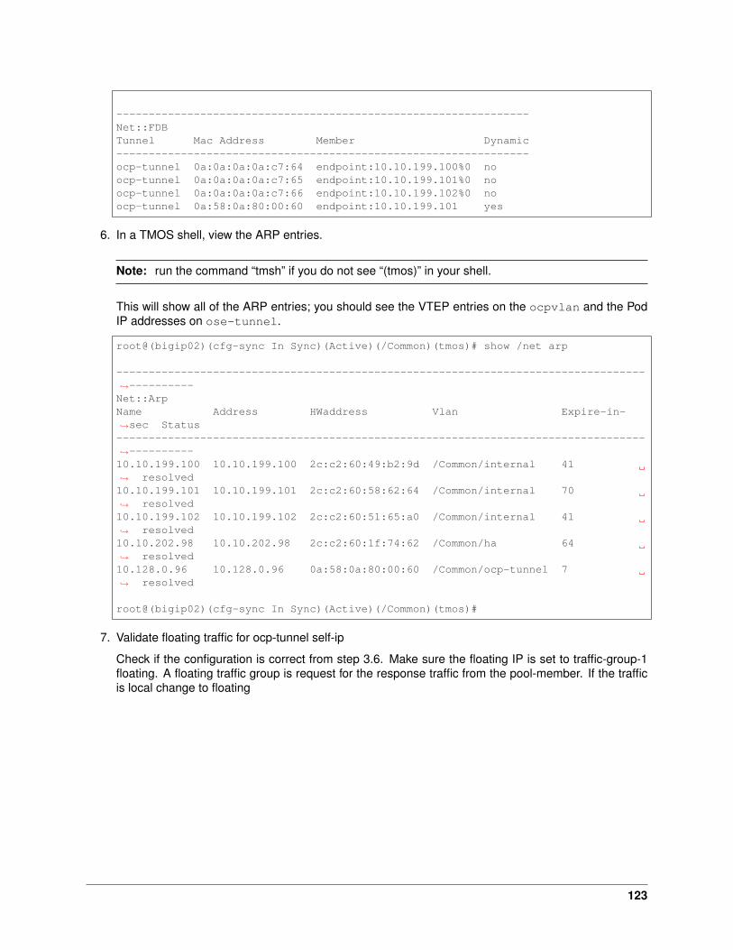
----------------------------------------------------------------Net::FDBTunnel Mac Address Member Dynamic----------------------------------------------------------------ocp-tunnel 0a:0a:0a:0a:c7:64 endpoint:10.10.199.100%0 noocp-tunnel 0a:0a:0a:0a:c7:65 endpoint:10.10.199.101%0 noocp-tunnel 0a:0a:0a:0a:c7:66 endpoint:10.10.199.102%0 noocp-tunnel 0a:58:0a:80:00:60 endpoint:10.10.199.101 yes
6. In a TMOS shell, view the ARP entries.
Note: run the command “tmsh” if you do not see “(tmos)” in your shell.
This will show all of the ARP entries; you should see the VTEP entries on the ocpvlan and the PodIP addresses on ose-tunnel.
root@(bigip02)(cfg-sync In Sync)(Active)(/Common)(tmos)# show /net arp
----------------------------------------------------------------------------------→˓----------Net::ArpName Address HWaddress Vlan Expire-in-→˓sec Status----------------------------------------------------------------------------------→˓----------10.10.199.100 10.10.199.100 2c:c2:60:49:b2:9d /Common/internal 41→˓ resolved10.10.199.101 10.10.199.101 2c:c2:60:58:62:64 /Common/internal 70→˓ resolved10.10.199.102 10.10.199.102 2c:c2:60:51:65:a0 /Common/internal 41→˓ resolved10.10.202.98 10.10.202.98 2c:c2:60:1f:74:62 /Common/ha 64→˓ resolved10.128.0.96 10.128.0.96 0a:58:0a:80:00:60 /Common/ocp-tunnel 7→˓ resolved
root@(bigip02)(cfg-sync In Sync)(Active)(/Common)(tmos)#
7. Validate floating traffic for ocp-tunnel self-ip
Check if the configuration is correct from step 3.6. Make sure the floating IP is set to traffic-group-1floating. A floating traffic group is request for the response traffic from the pool-member. If the trafficis local change to floating
123

change to floating
Connect to the viutal IP address
124
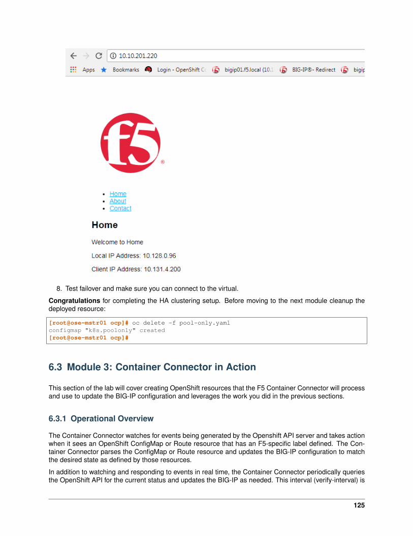
8. Test failover and make sure you can connect to the virtual.
Congratulations for completing the HA clustering setup. Before moving to the next module cleanup thedeployed resource:
[root@ose-mstr01 ocp]# oc delete -f pool-only.yamlconfigmap "k8s.poolonly" created[root@ose-mstr01 ocp]#
6.3 Module 3: Container Connector in Action
This section of the lab will cover creating OpenShift resources that the F5 Container Connector will processand use to update the BIG-IP configuration and leverages the work you did in the previous sections.
6.3.1 Operational Overview
The Container Connector watches for events being generated by the Openshift API server and takes actionwhen it sees an OpenShift ConfigMap or Route resource that has an F5-specific label defined. The Con-tainer Connector parses the ConfigMap or Route resource and updates the BIG-IP configuration to matchthe desired state as defined by those resources.
In addition to watching and responding to events in real time, the Container Connector periodically queriesthe OpenShift API for the current status and updates the BIG-IP as needed. This interval (verify-interval) is
125

30 seconds by default but is a startup value that can be modified.
An instance of the Container Connector can watch for changes in all namespaces (projects), a singlenamespace or a discrete list of namespaces. Additionally, an instance of the Container Connector is con-figured to make configuration changes in a single non-Common BIG-IP partition.
OpenShift runs on top of Kubernetes and the same Container Connector works for both, but many of theContainer Connector features apply to both while some apply only to OpenShift, like Routes, while others,like Ingress, apply only to Kubernetes.
You can find detailed information about configuring, deploying and using the F5 Container Connector aswell as configuration options for ConfigMaps and Routes https://clouddocs.f5.com/containers/v2/#
Additionally, you can get more detailed information about an OpenShift command by using oc <command>-help. So, for example, if you wanted to find out more about the oc create command, you would do thefollowing:
[root@ose-mstr01 garrison]# oc create -help
In the following exercises, you will create the following OpenShift resource types:
• ConfigMaps
• Routes
Additionally, you will also create variations of each resource type.
Note: You will use the same Windows jumpbox as you used in the previous sections to complete theexercises in this section.
Unless otherwise noted, all the resource definition yaml files have been pre-created and can be found onthe ose-master server under /root/agility2018/apps/module3
6.3.2 Exercise 1: ConfigMap - Basic
An OpenShift ConfigMap is one of the resource types that the F5 Container Connector watches for. TheContainer Connector will read the ConfigMap and create a virtual server, node(s), a pool, pool member(s)and a pool health monitor.
In this exercise, you will create a ConfigMap that defines the objects that the Container Connector shouldconfigure on the BIG-IP.
To complete this exercise, you will perform the following steps:
• Step 1: Deploy demo application
• Step 2: Create a service to expose the demo application
• Step 3: Create a ConfigMap that declares desired BIG-IP configuration
• Step 4: Review the BIG-IP configuration
• Step 5: Test the application
• Step 6: Scale the application
• Step 7: Test the scaled application
• Step 8: Cleanup deployed resources
126
Step 1: Deploy demo application
From the ose-master, review the following Deployment configuration: f5-demo-app-deployment.yaml
1 apiVersion: extensions/v1beta12 kind: Deployment3 metadata:4 name: f5-demo-app5 namespace: f5demo6 spec:7 replicas: 18 template:9 metadata:
10 labels:11 app: f5-demo-app12 spec:13 containers:14 - name: f5-demo-app15 image: chen23/f5-demo-app:openshift16 ports:17 - containerPort: 808018 protocol: TCP
Now that you have reviewed the Deployment,you need to actually create the Deployment by deploying it toOpenShift by using the oc create command.
From ose-master server, run the following command:
Attention: Be sure to change the working directory on ose-mstr01:
cd /root/agility2018/apps/module3
[root@ose-mstr01 module3]# oc create -f f5-demo-app-deployment.yamldeployment "f5-demo-app" created
Step 2: Create Service to expose application
In order for an application to be accessible outside of the OpenShift cluster, a Service must be created.The Service uses a label selector to reference the application to be exposed. Additionally, the service alsospecifies the container port (8080) that the application is listening on.
From ose-master, review the following Service: f5-demo-app-service.yaml
1 apiVersion: v12 kind: Service3 metadata:4 name: f5-demo-app5 labels:6 name: f5-demo-app7 namespace: f5demo8 spec:9 type: ClusterIP
10 ports:11 - port: 808012 targetPort: 808013 selector:14 app: f5-demo-app
127

Now that you have reviewed the Service,you need to actually create the Service by deploying it to OpenShiftby using the oc create command.
From ose-master server, run the following command:
[root@ose-mstr01 module3]# oc create -f f5-demo-app-service.yamlservice "f5-demo-app" created
Step 3: Create ConfigMap
A ConfigMap is used to define the BIG-IP objects that need to be created to enable access to the applicationvia the BIG-IP.
The label, f5type: virtual-server, in the ConfigMap definition is what triggers the F5 Container Connectorto process this ConfigMap.
In addition to the label, there are several F5-specific sections defined:
• virtualServer: Beginning of F5-specific configuration
• backend: Represents the server-side of the virtual server definition
• healthMonitors: Health monitor definition for the pool
• frontend: Represents the client-side of the virtual server
• virtualAddress: IP address and port of virtual server
A ConfigMap points to a Service which points to one or more Pods where the application is running.
From ose-master, review the ConfigMap resource f5-demo-app-configmap.yaml
1 kind: ConfigMap2 apiVersion: v13 metadata:4 # name of the resource to create on the BIG-IP5 name: f5-demo-app6 # The namespace to create the object in.7 # The k8s-bigip-ctlr watches all namespaces by default (as of v1.1).8 # If the k8s-bigip-ctlr is watching a specific namespace(s),9 # this setting must match the namespace of the Service you want to proxy
10 # -AND- the namespace(s) the k8s-bigip-ctlr watches.11 namespace: f5demo12 labels:13 # tells the k8s-bigip-ctlr to watch this ConfigMap14 f5type: virtual-server15 data:16 # NOTE: schema v0.1.4 is required as of k8s-bigip-ctlr v1.3.017 schema: "f5schemadb://bigip-virtual-server_v0.1.7.json"18 data: |19 {20 "virtualServer": {21 "backend": {22 "servicePort": 8080,23 "serviceName": "f5-demo-app",24 "healthMonitors": [{25 "interval": 30,26 "protocol": "http",27 "send": "GET /\r\n",28 "timeout": 12029 }]30 },
128
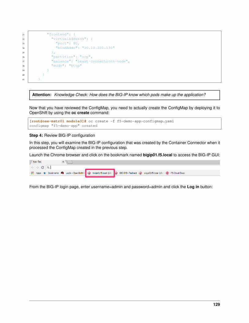
31 "frontend": {32 "virtualAddress": {33 "port": 80,34 "bindAddr": "10.10.201.130"35 },36 "partition": "ocp",37 "balance": "least-connections-node",38 "mode": "http"39 }40 }41 }
Attention: Knowledge Check: How does the BIG-IP know which pods make up the application?
Now that you have reviewed the ConfigMap, you need to actually create the ConfigMap by deploying it toOpenShift by using the oc create command:
[root@ose-mstr01 module3]# oc create -f f5-demo-app-configmap.yamlconfigmap "f5-demo-app" created
Step 4: Review BIG-IP configuration
In this step, you will examine the BIG-IP configuration that was created by the Container Connector when itprocessed the ConfigMap created in the previous step.
Launch the Chrome browser and click on the bookmark named bigip01.f5.local to access the BIG-IP GUI:
From the BIG-IP login page, enter username=admin and password=admin and click the Log in button:
129

Navigate to Local Traffic –> Network Map and change the partition to ocp using the dropdown in theupper right. The network map view shows a virtual server, pool and pool member. All of these objects werecreated by the Container Connector using the declarations defined in the ConfigMap.
Attention: Knowledge Check: In the network map view, what OpenShift object type does the poolmember IP address represent? How was the IP address assigned?
To view the IP address of the virtual server, hover your cursor over the name of the virtual server:
130

Attention: Knowledge Check: What OpenShift resource type was used to define the virtual server IPaddress?
Step 5: Test the application
In this step, you will use the Chrome browser to access the application you previously deployed to OpenShift.
Open a new browser tab and enter the IP address assigned to the virtual server in to the address bar:
Note: On the application page, the Server IP is the pool member (pod) IP address; the Server Port is theport of the virtual server; and the Client IP is the IP address of the Windows jumpbox you are using.
Step 6: Scale the application
The application deployed in step #1 is a single replica (instance). In this step,you are going to increase thenumber of replicas and then check the BIG-IP configuration to see what’s changed.
131

When the deployment replica count is scaled up or scaled down, an OpenShift event is generated and theContainer Connector sees the event and adds or removes pool members as appropriate.
To scale the number of replicas, you will use the OpenShift oc scale command. You will be scaling thedemo app deployment and so You first need to get the name of the deployment.
From ose-master, issue the following command:
[root@ose-mstr01 module3]# oc get deployment -n f5demoNAME DESIRED CURRENT UP-TO-DATE AVAILABLE AGEf5-demo-app 1 1 1 1 1m
You can see from the output that the deployment is named f5-demo-app. You will use that name for thenext command.
From the ose-master host, entering the following command to set the replica count for the deployment to 10instances:
[root@ose-mstr01 module3]# oc scale --replicas=10 deployment/f5-demo-app -n f5demodeployment "f5-demo-app" scaled
Step 7: Review the BIG-IP configuration
In this step, you will examine the BIG-IP configuration for changes that occured after the application wasscaled up.
Navigate to Local Traffic –> Network Map and change the partition to ocp using the dropdown in theupper right.
Attention: Knowledge Check: How many pool members are shown in the network map view? Whatdo you think would happen if you scaled the deployment back to one replica?
Step 8: Test the scaled application
In this step, you will use the Chrome browser to access the application that you scaled to 10 replicas in theprevious step.
132

Open a new Chrome browser tab and enter the IP address assigned to the virtua server in to the addressbar:
If you reload the page every few seconds, you should see the Server IP address change. Because there ismore than one instance of the application running, the BIG-IP load balances the application traffic amongstmultiple pods.
Step 9: Cleanup deployed resources
In this step, you will remove the OpenShift Deployment, Service and ConfigMap resources you created inthe previous steps using the OpenShift oc delete command.
From ose-master server, issue the following commands:
[root@ose-mstr01 tmp]# oc delete -f f5-demo-app-configmap.yamlconfigmap "f5-demo-app" deleted
[root@ose-mstr01 tmp]# oc delete -f f5-demo-app-deployment.yamldeployment "f5-demo-app" deleted
[root@ose-mstr01 module3]# oc delete -f f5-demo-app-service.yamlservice "f5-demo-app" deleted
6.3.3 Exercise 2: Route - Basic
An OpenShift Route is one of the resource types that the F5 Container Connector watches for. A Routedefines a hostname or URI mapping to an application. For example, the hostname “customer.example.com”could map to the application “customer”, hostname “catalog.example.com”, might map to the application“catalog”, etc.
Similarly, a Route can refer to a URI path so, for example, the URI path “/customer” might map to theapplication called “customer” and URI path “/catalog”, might map to the application called “catalog”. If aRoute only specifies URI paths, the Route applies to all HTTP request hostnames.
133

Additionally, a Route can refer to both a hostname and a URI path such as mycompany.com/customer ormycompany.com/catalog
The F5 Container Connector reads the Route resource and creates a virtual server, node(s), a pool perroute path and pool members. Additionally, the Container Connector creates a layer 7 BIG-IP traffic policyand associates it with the virtual server. This layer 7 traffic policy evaluates the hostname or URI path fromthe request and forwards the traffic to the pool associated with that path.
A Route points to a Service which points to one or more Pods where the application is running.
Note: All Route resources share two virtual servers:
• ose-vserver for HTTP traffic, and
• https-ose-vserver for HTTPS traffic
The Container Connector assigns the names shown above by default. To set custom names, define route-http-vserver and route-https-vserver in the BIG-IP Container Connector Deployment. Please see thedocumentation at: http://clouddocs.f5.com for more details.
To complete this exercise, you will perform the following steps:
• Step 1: Deploy demo application and associated Service
• Step 2: Create a Route that defines routing rules based on hostname
• Step 3: Review the BIG-IP configuration
Step 1: Deploy demo application and its associated Service
In the previous exercise, you created the Deployment and Service separately. This step demonstratescreating both the Deployment and the Service from single configuration file. A separator of 3 dashes (---)is used to separate one resource definition from the next resource definition.
From ose-master, review the following deployment: f5-demo-app-route-deployment.yaml
1 apiVersion: extensions/v1beta12 kind: Deployment3 metadata:4 name: f5-demo-app-route5 spec:6 replicas: 17 template:8 metadata:9 labels:
10 app: f5-demo-app-route11 spec:12 containers:13 - name: f5-demo-app-route14 image: chen23/f5-demo-app:openshift15 ports:16 - containerPort: 808017 protocol: TCP18 ---19 apiVersion: v120 kind: Service21 metadata:22 name: f5-demo-app-route23 labels:24 name: f5-demo-app-route
134
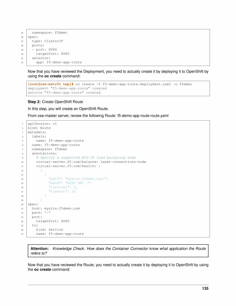
25 namespace: f5demo26 spec:27 type: ClusterIP28 ports:29 - port: 808030 targetPort: 808031 selector:32 app: f5-demo-app-route
Now that you have reviewed the Deployment, you need to actually create it by deploying it to OpenShift byusing the oc create command:
[root@ose-mstr01 tmp]# oc create -f f5-demo-app-route-deployment.yaml -n f5demodeployment "f5-demo-app-route" createdservice "f5-demo-app-route" created
Step 2: Create OpenShift Route
In this step, you will create an OpenShift Route.
From ose-master server, review the following Route: f5-demo-app-route-route.yaml
1 apiVersion: v12 kind: Route3 metadata:4 labels:5 name: f5-demo-app-route6 name: f5-demo-app-route7 namespace: f5demo8 annotations:9 # Specify a supported BIG-IP load balancing mode
10 virtual-server.f5.com/balance: least-connections-node11 virtual-server.f5.com/health: |12 [13 {14 "path": "mysite.f5demo.com/",15 "send": "HTTP GET /",16 "interval": 5,17 "timeout": 1018 }19 ]20 spec:21 host: mysite.f5demo.com22 path: "/"23 port:24 targetPort: 808025 to:26 kind: Service27 name: f5-demo-app-route
Attention: Knowledge Check: How does the Container Connector know what application the Routerefers to?
Now that you have reviewed the Route, you need to actually create it by deploying it to OpenShift by usingthe oc create command:
135

[root@ose-mstr01 tmp]# oc create -f f5-demo-app-route-route.yaml -n f5demoroute "f5-demo-app-route" created
Step 3: Review the BIG-IP configuration
In this step, you will examine the BIG-IP configuration for changes that occured after the the OpenShiftRoute was deployoed.
Using the Chrome browser, navigate to Local Traffic –> Network Map and change the partition to ocpusing the dropdown in the upper right.
The network map view shows two virtual servers that were created by the Container Connector when itprocssed the Route resource created in the previous step. One virtual server is for HTTP client traffic andthe other virtual server is for HTTPS client traffic.
To view the IP address of the virtual server, hover your cursor over the virtual server named ocp-vserver
Attention: Knowledge Check: Which OpenShift resource type defines the names of the two virtualservers?
Next, you will view the traffic policy that was created by the Container Connector when it processed theOpenShift Route.
Navigate to Local Traffic –> Policies –> Policy List and change the partition to ocp using the dropdownin the upper right.
136
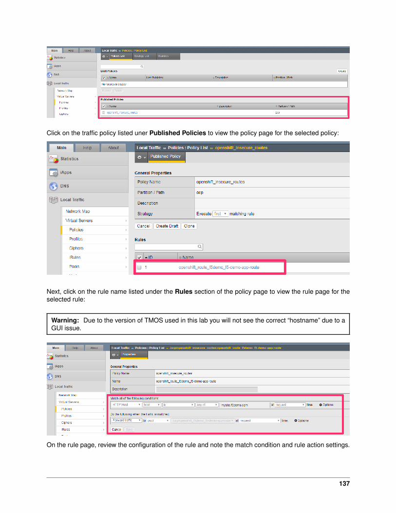
Click on the traffic policy listed uner Published Policies to view the policy page for the selected policy:
Next, click on the rule name listed under the Rules section of the policy page to view the rule page for theselected rule:
Warning: Due to the version of TMOS used in this lab you will not see the correct “hostname” due to aGUI issue.
On the rule page, review the configuration of the rule and note the match condition and rule action settings.
137

Attention: Knowledge Check: Which OpenShift resource type defines the hostname to match against?
Step 5: Test the application
In this step, you will use the Chrome browser to access the application you previously deployed.
Because the Route resource you created specifies a hostname for the path, you will need to use a hostnameinstead of an IP address to access the demo application.
Open a new Chrome browser tab and enter the hostname mysite.f5demo.com in to the address bar:
On the application page, the Server IP is the pool member (pod) IP address; the Server Port is the port ofthe virtual server; and the Client IP is the IP address of the Windows jumpbox you are using.
Step 6: Cleanup deployed resources
In this step, you will remove the Deployment, Service and Route resources you created in the previoussteps using the OpenShift oc delete command.
From ose-master server, issue the following commands:
[root@ose-mstr01 tmp]# oc delete -f f5-demo-app-route-route.yaml -n f5demoroute "f5-demo-app-route" deleted
[root@ose-mstr01 tmp]# oc delete -f f5-demo-app-route-deployment.yaml -n f5demodeployment "f5-demo-app-route" deletedservice "f5-demo-app-route" deleted
6.3.4 Exercise 3: Route - Blue/Green Testing
The F5 Container Connector supports Blue/Green application testing e.g testing two different versions ofthe same application, by using the weight parameter of OpenShift Routes. The weight parameter allowsyou to establish relative ratios between application Blue and application Green. So, for example, if the first
138

route specifies a weight of 20 and the second a weight of 10, the application associated with the first routeill get twice the number of requests as the application associated with the second route.
Just as in the previous exercise, the F5 Container Connector reads the Route resource and creates a virtualserver, node(s), a pool per route path and pool members.
However, in order to support Blue/Green testing using OpenShift Routes, the Container Connector createsan iRule and a datagroup on the BIG-IP. Troubleshooting handles the connection routing based on theassigned weights.
Note: At smaller request volumes, the ratio of requests to the Blue application and the requests to theGreen application may not match the relative weights assigned in the OpenShift Route. However, as thenumber of requests increases, the ratio of requests between the Blue application and the Green applicationshould closely match the weights assigned in the OpenShift Route.
To complete this exercise, you will perform the following steps:
• Step 1: Deploy version 1 and version 2 of demo application and their related Services
• Step 2: Create an OpenShift Route for Blue/Green testing
• Step 3: Review BIG-IP configuration
• Step 4: Test the application
• Step 5: Generate some request traffic
• Step 6: Review the BIG-IP configuration
• Step 7: Cleanup deployed resources
Step 1: Deploy version 1 and version 2 of demo application and their associated Services
From ose-master, review the following deployment: f5-demo-app-bg-deployment.yaml
1 apiVersion: extensions/v1beta12 kind: Deployment3 metadata:4 name: node-blue5 namespace: f5demo6 spec:7 replicas: 18 template:9 metadata:
10 labels:11 run: node-blue12 spec:13 containers:14 - image: "chen23/f5-demo-app"15 env:16 - name: F5DEMO_APP17 value: "website"18 - name: F5DEMO_NODENAME19 value: "Node Blue (No SSL)"20 - name: F5DEMO_NODENAME_SSL21 value: "Node Blue (SSL)"22 - name: F5DEMO_COLOR23 value: "0000FF"24 - name: F5DEMO_COLOR_SSL25 value: "0000FF"26 imagePullPolicy: IfNotPresent
139

27 name: node-blue28 ports:29 - containerPort: 8030 - containerPort: 44331 protocol: TCP32
33 ---34
35 apiVersion: v136 kind: Service37 metadata:38 name: node-blue39 labels:40 run: node-blue41 namespace: f5demo42 spec:43 ports:44 - port: 8045 protocol: TCP46 targetPort: 8047 name: http48 - port: 44349 protocol: TCP50 targetPort: 44351 name: https52 type: ClusterIP53 selector:54 run: node-blue55
56 ---57
58 apiVersion: extensions/v1beta159 kind: Deployment60 metadata:61 name: node-green62 namespace: f5demo63 spec:64 replicas: 165 template:66 metadata:67 labels:68 run: node-green69 spec:70 containers:71 - image: "chen23/f5-demo-app"72 env:73 - name: F5DEMO_APP74 value: "website"75 - name: F5DEMO_NODENAME76 value: "Node Green (No SSL)"77 - name: F5DEMO_COLOR78 value: "99FF99"79 - name: F5DEMO_NODENAME_SSL80 value: "Node Green (SSL)"81 - name: F5DEMO_COLOR_SSL82 value: "00FF00"83 imagePullPolicy: IfNotPresent84 name: node-green
140
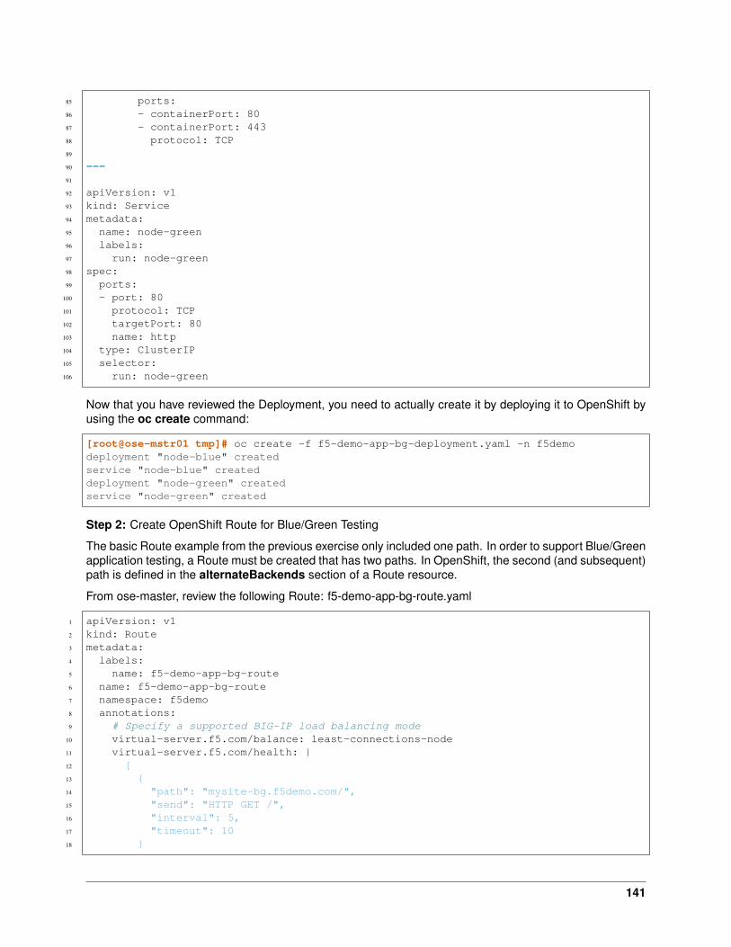
85 ports:86 - containerPort: 8087 - containerPort: 44388 protocol: TCP89
90 ---91
92 apiVersion: v193 kind: Service94 metadata:95 name: node-green96 labels:97 run: node-green98 spec:99 ports:
100 - port: 80101 protocol: TCP102 targetPort: 80103 name: http104 type: ClusterIP105 selector:106 run: node-green
Now that you have reviewed the Deployment, you need to actually create it by deploying it to OpenShift byusing the oc create command:
[root@ose-mstr01 tmp]# oc create -f f5-demo-app-bg-deployment.yaml -n f5demodeployment "node-blue" createdservice "node-blue" createddeployment "node-green" createdservice "node-green" created
Step 2: Create OpenShift Route for Blue/Green Testing
The basic Route example from the previous exercise only included one path. In order to support Blue/Greenapplication testing, a Route must be created that has two paths. In OpenShift, the second (and subsequent)path is defined in the alternateBackends section of a Route resource.
From ose-master, review the following Route: f5-demo-app-bg-route.yaml
1 apiVersion: v12 kind: Route3 metadata:4 labels:5 name: f5-demo-app-bg-route6 name: f5-demo-app-bg-route7 namespace: f5demo8 annotations:9 # Specify a supported BIG-IP load balancing mode
10 virtual-server.f5.com/balance: least-connections-node11 virtual-server.f5.com/health: |12 [13 {14 "path": "mysite-bg.f5demo.com/",15 "send": "HTTP GET /",16 "interval": 5,17 "timeout": 1018 }
141
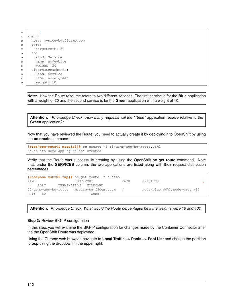
19 ]20 spec:21 host: mysite-bg.f5demo.com22 port:23 targetPort: 8024 to:25 kind: Service26 name: node-blue27 weight: 2028 alternateBackends:29 - kind: Service30 name: node-green31 weight: 10
Note: How the Route resource refers to two different services: The first service is for the Blue applicationwith a weight of 20 and the second service is for the Green application with a weight of 10.
Attention: Knowledge Check: How many requests will the **Blue* application receive relative to theGreen application?*
Now that you have reviewed the Route, you need to actually create it by deploying it to OpenShift by usingthe oc create command:
[root@ose-mstr01 module3]# oc create -f f5-demo-app-bg-route.yamlroute "f5-demo-app-bg-route" created
Verify that the Route was successfully creating by using the OpenShift oc get route command. Notethat, under the SERVICES column, the two applications are listed along with their request distributionpercentages.
[root@ose-mstr01 tmp]# oc get route -n f5demoNAME HOST/PORT PATH SERVICES→˓ PORT TERMINATION WILDCARDf5-demo-app-bg-route mysite-bg.f5demo.com / node-blue(66%),node-green(33→˓%) 80 None
Attention: Knowledge Check: What would the Route percentages be if the weights were 10 and 40?
Step 3: Review BIG-IP configuration
In this step, you will examine the BIG-IP configuration for changes made by the Container Connector afterthe the OpenShift Route was deployoed.
Using the Chrome web browser, navigate to Local Traffic –> Pools –> Pool List and change the partitionto ocp using the dropdown in the upper right.
142
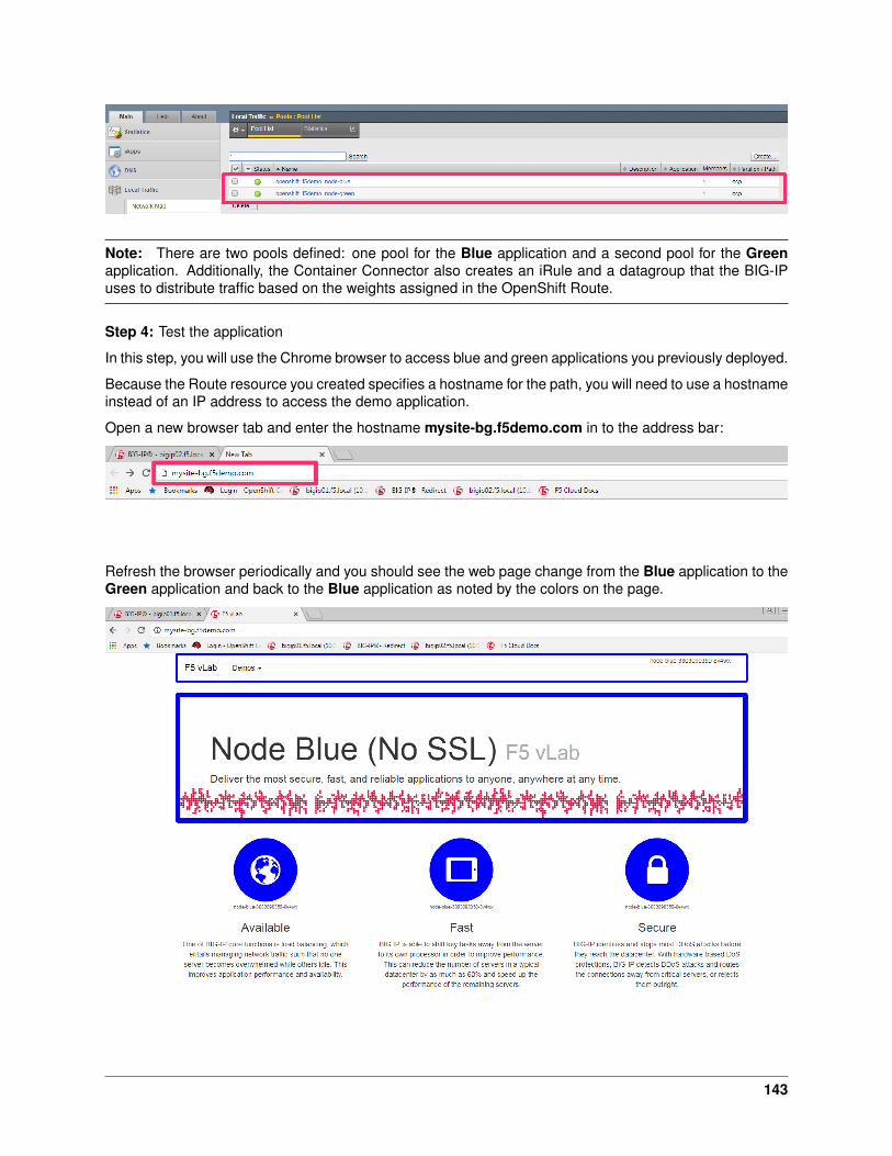
Note: There are two pools defined: one pool for the Blue application and a second pool for the Greenapplication. Additionally, the Container Connector also creates an iRule and a datagroup that the BIG-IPuses to distribute traffic based on the weights assigned in the OpenShift Route.
Step 4: Test the application
In this step, you will use the Chrome browser to access blue and green applications you previously deployed.
Because the Route resource you created specifies a hostname for the path, you will need to use a hostnameinstead of an IP address to access the demo application.
Open a new browser tab and enter the hostname mysite-bg.f5demo.com in to the address bar:
Refresh the browser periodically and you should see the web page change from the Blue application to theGreen application and back to the Blue application as noted by the colors on the page.
143
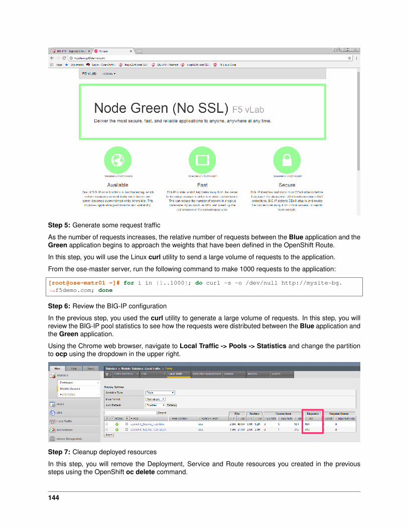
Step 5: Generate some request traffic
As the number of requests increases, the relative number of requests between the Blue application and theGreen application begins to approach the weights that have been defined in the OpenShift Route.
In this step, you will use the Linux curl utility to send a large volume of requests to the application.
From the ose-master server, run the following command to make 1000 requests to the application:
[root@ose-mstr01 ~]# for i in {1..1000}; do curl -s -o /dev/null http://mysite-bg.→˓f5demo.com; done
Step 6: Review the BIG-IP configuration
In the previous step, you used the curl utility to generate a large volume of requests. In this step, you willreview the BIG-IP pool statistics to see how the requests were distributed between the Blue application andthe Green application.
Using the Chrome web browser, navigate to Local Traffic -> Pools -> Statistics and change the partitionto ocp using the dropdown in the upper right.
Step 7: Cleanup deployed resources
In this step, you will remove the Deployment, Service and Route resources you created in the previoussteps using the OpenShift oc delete command.
144
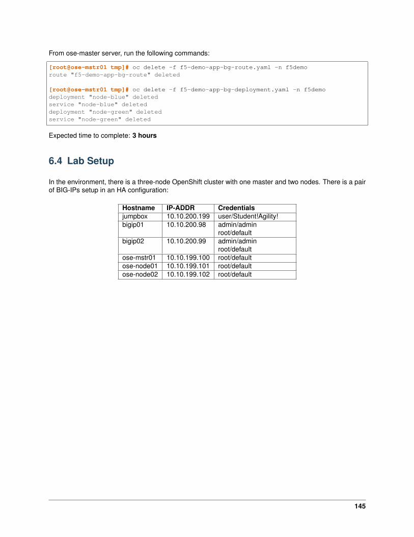
From ose-master server, run the following commands:
[root@ose-mstr01 tmp]# oc delete -f f5-demo-app-bg-route.yaml -n f5demoroute "f5-demo-app-bg-route" deleted
[root@ose-mstr01 tmp]# oc delete -f f5-demo-app-bg-deployment.yaml -n f5demodeployment "node-blue" deletedservice "node-blue" deleteddeployment "node-green" deletedservice "node-green" deleted
Expected time to complete: 3 hours
6.4 Lab Setup
In the environment, there is a three-node OpenShift cluster with one master and two nodes. There is a pairof BIG-IPs setup in an HA configuration:
Hostname IP-ADDR Credentialsjumpbox 10.10.200.199 user/Student!Agility!bigip01 10.10.200.98 admin/admin
root/defaultbigip02 10.10.200.99 admin/admin
root/defaultose-mstr01 10.10.199.100 root/defaultose-node01 10.10.199.101 root/defaultose-node02 10.10.199.102 root/default
145

Top Related