


Languages
Pages
Legal


Agenda and Objectives
Trane Engineers Newsletter Live Series
Fans in Air-Handling Systems
Fans used in air-handling systems often have a significant impact on energy use and acoustics. How much of an impact depends on
how a fan is selected, installed, and operated. Trane applications engineers discuss fan performance curves and fan laws, different
fan types (fan blade shape, housed vs. plenum fans, direct-drive plenum fans, fan arrays), how a fan interacts with various
types of systems, considerations when selecting a fan (efficiency, acoustics, footprint), and the ASHRAE Standard 90.1
fan power limitations.
By attending this event you will be able to:
1. Summarize how to use fan performance curves
2. How to select, install, and operate fans to avoid problems related to inadequate airflow or excessive noise
3. When to select the different fan types (housed vs. plenum, belt-drive vs. direct-drive, single fan vs. a fan array)
4. How to design fan systems to meet the prescriptive requirements of ASHRAE Standard 90.1-2007
Agenda
1) Fan performance curves
a) How developed (lab setup, difference with AHU vs. RTU)
b) What they are for (selection) and not for (predicting field performance)
c) Fan laws
d) Interaction of fans in a system (system curve)
2) Fan/unit selection considerations
a) Types of fans (energy – bhp or motor input kW, acoustics, footprint, maintenance, redundancy)
b) Impact of system configuration on fan selection (examples)
c) System effect (example using AMCA guide)
d) Acoustics topics
3) Common problems
a) Fan is not delivering enough airflow
b) Fan is making too much noise
4) Meeting ASHRAE 90.1 requirements
a) Option 1 vs. Option 2 (fan power limitation)
b) Lowering bhp/cfm
5) Summary
Agenda_APPCMC038-fans.ai 1 6/16/2014 4:08:01 PM

Presenters
Trane Engineers Newsletter Live Series
Fans in Air-Handling Systems(2010)
Dave Guckelberger | application engineer | Trane
Dave has a wide range of product and system responsibilities as a Trane applications engineer. His expertise includes acoustic
analysis and modeling of HVAC systems, electrical distribution system design, and the equipment-room design requirements
established by ASHRAE Standard 15. He also provides research and interpretation on how building, mechanical, and fire codes
impact HVAC equipment and systems.
In addition to traditional applications engineering support, Dave has authored a variety
of technical articles on subjects ranging from acoustics to ECM motors to codes. After graduating from Michigan Tech with a
BSME in thermo-fluids, he joined Trane as a development engineer in 1982 and moved into his current position in
Applications Engineering in 1987.
Dustin Meredith | application engineer | Trane
Dustin is an application engineer with expertise in sound predictions, fan selection, and vibration analysis. He also leads
development and implementationprojects for new and upcoming air-handling options. Dustin has authored various technical
engineering bulletins and applications engineering manuals.
Dustin is a corresponding member on ASHRAE TC 2.6 – Sound & Vibration Control – and ASHRAE TC5.1 – Fans. After graduating
from the University of Kentucky with BSME, BSCS and MBA degrees, hejoined Trane as a marketing engineer in 2000 and moved
into his current position in Application Engineering in 2005. Dustin is a member of ASHRAE and is the primary Trane contact for AMCA.
John Murphy | application engineer | Trane
John has been with Trane since 1993. His primary responsibility as an applications engineer is to aid design engineers and
Trane sales personnel in the proper design and application of HVAC systems. As a LEED Accredited Professional, he has helped
our customers and local offices on a wide range of LEED projects. His main areas of expertise include energy efficiency,
dehumidification, air-to-air energy recovery, psychrometry, ventilation, and ASHRAE Standards 15, 62.1, and 90.1.
John is the author of numerous Trane application manuals, Engineers Newsletters and ASHRAE Journal articles. He is a member of ASHRAE,
and has served on ASHRAE’s “Moisture Management in Buildings” and “Mechanical Dehumidifiers” technical committees. He was
a contributing author of the Advanced Energy Design Guide for K-12 Schools and the Advanced Energy Design Guide for Small Hospitals
and Health Care Facilities, and technical reviewer for The ASHRAE Guide for Buildings in Hot and Humid Climates.
Dennis Stanke | staff application engineer | Trane
With a BSME from the University of Wisconsin, Dennis joined Trane in 1973, as a controls development engineer. He is now a Staff
Applications Engineer specializing in airside systems including controls, ventilation, indoor air quality, and dehumidification.
He has written numerous applications manuals, newsletters, and technical articles and columns.
An ASHRAE Fellow, he recently served as Chairman for SSPC62.1, the ASHRAE committee responsible for Standard 62.1,
“Ventilation for Acceptable Indoor Air Quality,” and he serves on the USGBC LEED Technical Advisory Group for Indoor
Environmental Quality (the LEED EQ TAG).
Biographies_APPCMC038.ai 1 6/16/2014 4:09:59 PM
Fans in Air-Handling Systems© 2010 Trane, a business of Ingersoll-Rand. 1
Fans in Air-Handling Systems
© 2010 Trane a business of Ingersoll-Rand2
This program is registered with the AIA/CES and USGBC for LEED® continuing professional education. Credit earned on completion of this program will be reported to CES Records for AIA members.
The U.S. Green Building Council (USGBC) has approved the technical and instructional quality of this course for 1.5 GBCI CE hours towards the LEED Credential Maintenance Program. Certificates of Completion for LEED® credentialing available on request.
Continuing Education Credit

Fans in Air-Handling Systems© 2010 Trane, a business of Ingersoll-Rand. 2
© 2010 Trane a business of Ingersoll-Rand3
Copyrighted Materials
This presentation is protected by U.S. and international copyright laws. Reproduction, distribution, display, and use of the presentation without written permission of Trane is prohibited.
© 2010 Trane, a business of Ingersoll-Rand. All rights reserved.
© 2010 Trane a business of Ingersoll-Rand4
Fans in Air-Handling Systems
Today’s Topics
Fan fundamentals • Performance curves
Fan/unit selection considerations• Fan types
• Impact of system configuration
• System effect
• Acoustics
Common problems
ASHRAE 90.1 requirements

Fans in Air-Handling Systems© 2010 Trane, a business of Ingersoll-Rand. 3
© 2010 Trane a business of Ingersoll-Rand5
Today’s Presenters
Dennis Stanke
Staff ApplicationsEngineer
Dave Guckelberger
Applications Engineer
© 2010 Trane a business of Ingersoll-Rand6
Today’s Presenters
Dustin Meredith
Applications Engineer
John Murphy
Applications Engineer

Fans in Air-Handling Systems© 2010 Trane, a business of Ingersoll-Rand. 4
Fans in Air-Handling Systems
Fundamentals
Fan Performance Curves
© 2010 Trane a business of Ingersoll-Rand8
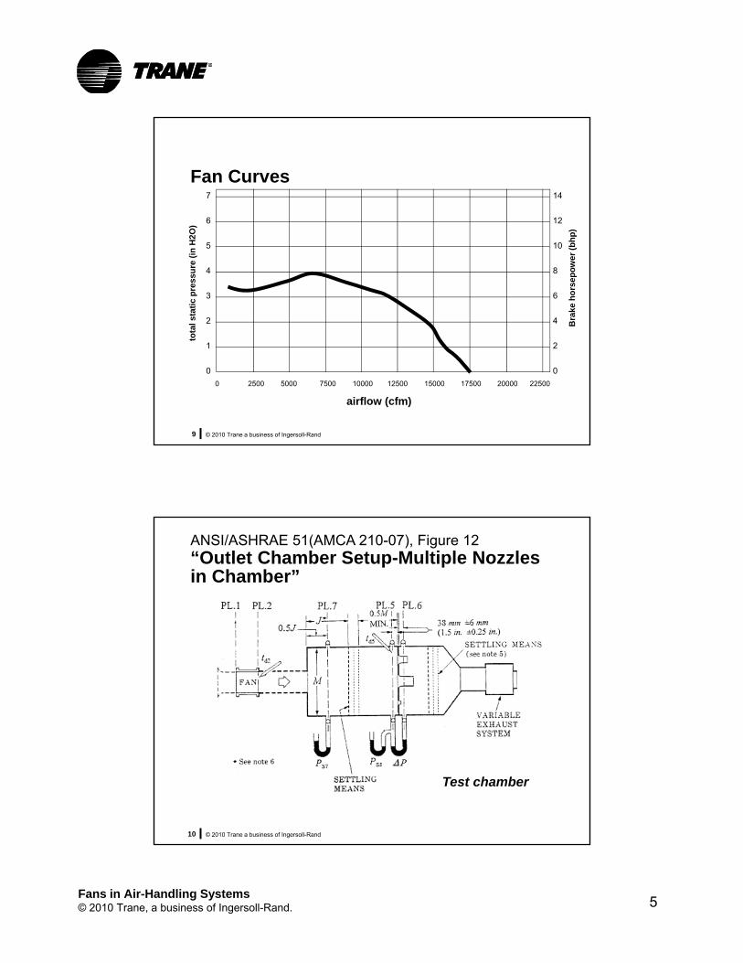
AMCA 210/ASHRAE 51“Laboratory Methods of Testing Fans for Aerodynamic Performance Rating”
Velocity Pressure: … that portion of the air pressure which exists by virtue of the rate of motion only.
Static Pressure: … that portion of the air pressure which exists by virtue of the degree of compression only.
Total Pressure: … the algebraic sum of the velocity pressure and the static pressure at a point.
Fans in Air-Handling Systems© 2010 Trane, a business of Ingersoll-Rand. 5
© 2010 Trane a business of Ingersoll-Rand9
Fan Curves7
6
5
4
3
2
1
0
0 2500 5000 7500 10000 12500 15000 17500 20000 22500
airflow (cfm)
tota
l sta
tic
pre
ssu
re (
in H
2O)
Bra
ke h
ors
epo
wer
(b
hp
)
14
12
10
8
6
4
2
0
© 2010 Trane a business of Ingersoll-Rand10
ANSI/ASHRAE 51(AMCA 210-07), Figure 12“Outlet Chamber Setup-Multiple Nozzles in Chamber”
Test chamber
Fans in Air-Handling Systems© 2010 Trane, a business of Ingersoll-Rand. 6
© 2010 Trane a business of Ingersoll-Rand11
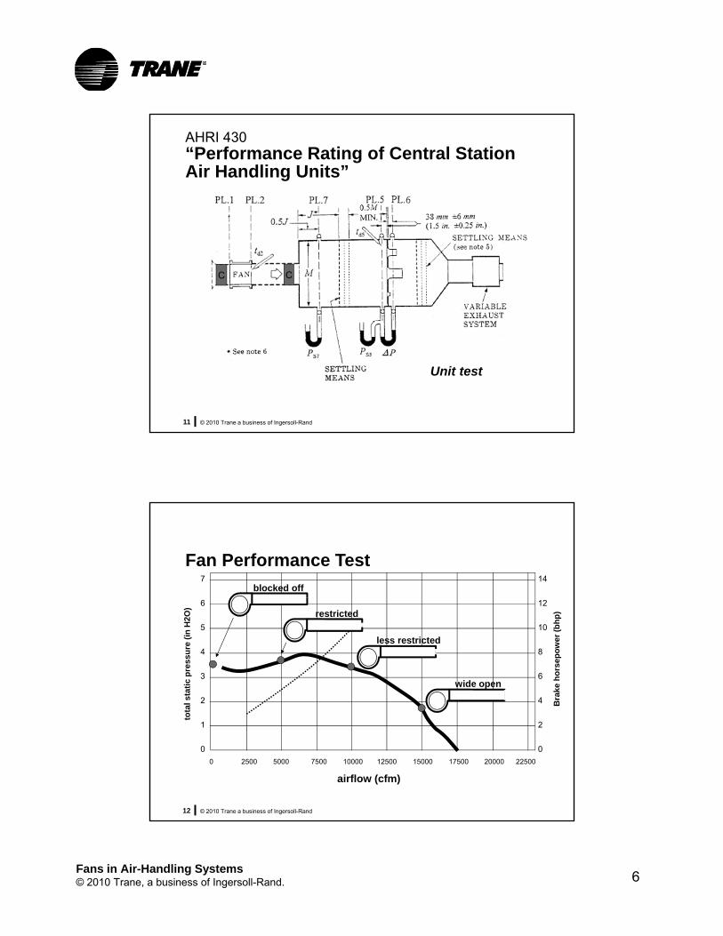
AHRI 430“Performance Rating of Central Station Air Handling Units”
C C
Unit test
© 2010 Trane a business of Ingersoll-Rand12
Fan Performance Test7
6
5
4
3
2
1
0
0 2500 5000 7500 10000 12500 15000 17500 20000 22500
airflow (cfm)
tota
l sta
tic
pre
ssu
re (
in H
2O)
blocked off
restricted
less restricted
wide open
14
12
10
8
6
4
2
0
Bra
ke h
ors
epo
wer
(b
hp
)
Fans in Air-Handling Systems© 2010 Trane, a business of Ingersoll-Rand. 7
© 2010 Trane a business of Ingersoll-Rand13
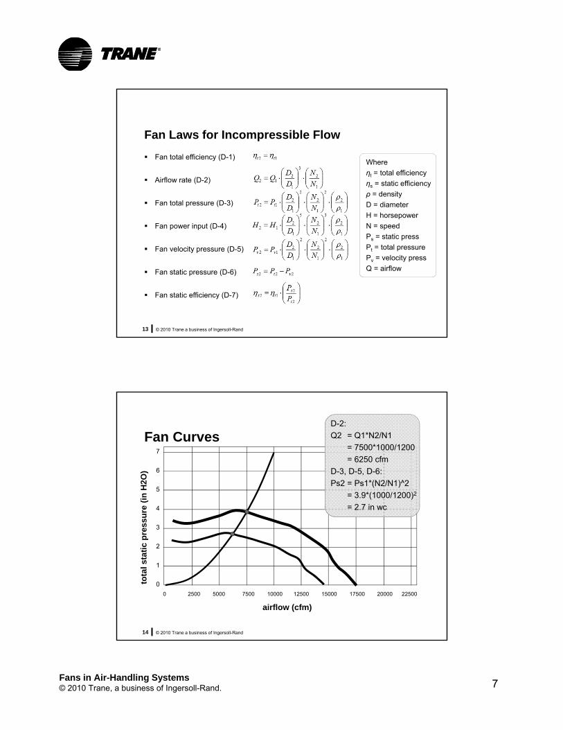
Fan Laws for Incompressible Flow
Fan total efficiency (D-1)
Airflow rate (D-2)
Fan total pressure (D-3)
Fan power input (D-4)
Fan velocity pressure (D-5)
Fan static pressure (D-6)
Fan static efficiency (D-7)
Where
ηt = total efficiency
ηs = static efficiency
ρ = density
D = diameter
H = horsepower
N = speed
Ps = static press
Pt = total pressure
Pv = velocity press
Q = airflow
© 2010 Trane a business of Ingersoll-Rand14
Fan Curves7
6
5
4
3
2
1
0
0 2500 5000 7500 10000 12500 15000 17500 20000 22500
airflow (cfm)
tota
l sta
tic
pre
ssu
re (
in H
2O)
D-2:
Q2 = Q1*N2/N1
= 7500*1000/1200
= 6250 cfm
D-3, D-5, D-6:
Ps2 = Ps1*(N2/N1)^2
= 3.9*(1000/1200)2
= 2.7 in wc
Fans in Air-Handling Systems© 2010 Trane, a business of Ingersoll-Rand. 1
© 2010 Trane a business of Ingersoll-Rand15
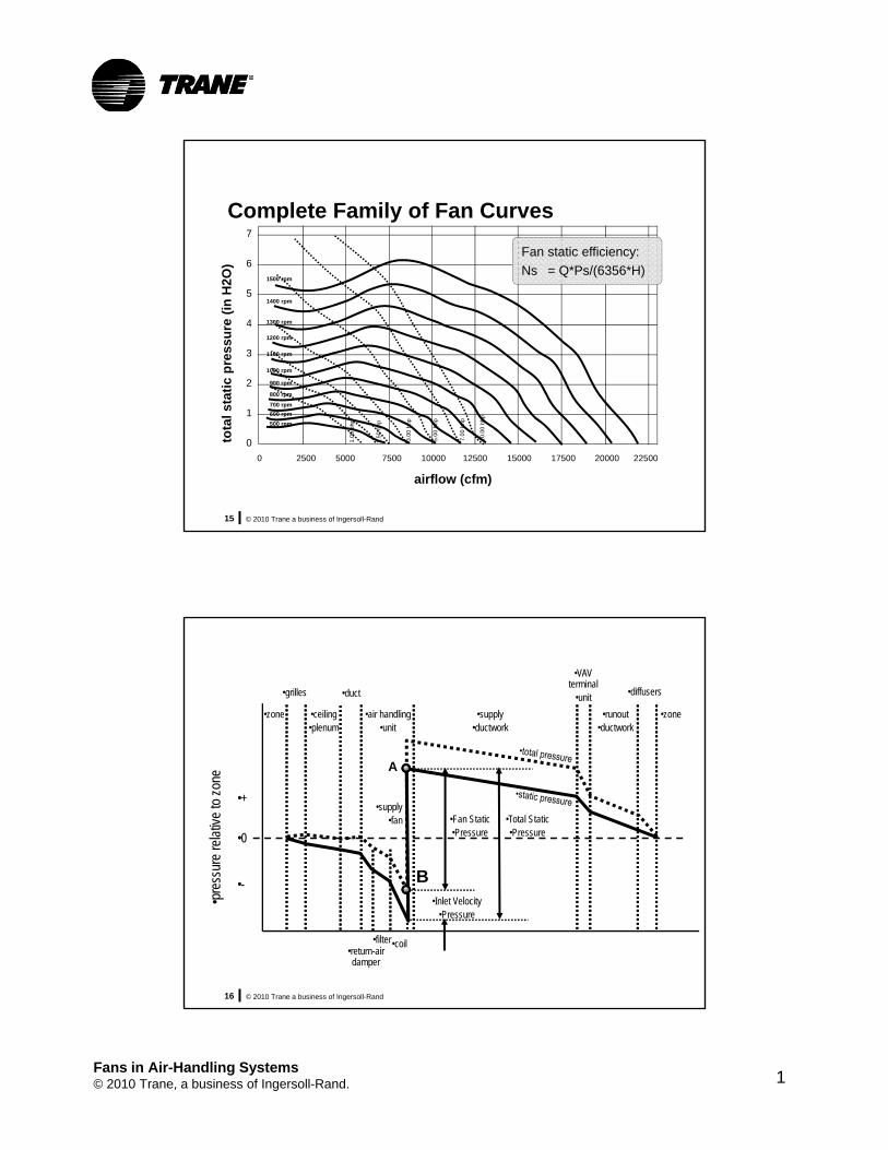
Complete Family of Fan Curves7
6
5
4
3
2
1
0
0 2500 5000 7500 10000 12500 15000 17500 20000 22500
airflow (cfm)
tota
l sta
tic
pre
ssu
re (
in H
2O)
Fan static efficiency:
Ns = Q*Ps/(6356*H)1500 rpm
1400 rpm
1100 rpm
1300 rpm
1200 rpm
1000 rpm
800 rpm
900 rpm
700 rpm
600 rpm
500 rpm
1.00
bhp
1.50
bhp
3.00
bhp
5.00
bhp
7.00
bhp
10.0
0 bh
p
© 2010 Trane a business of Ingersoll-Rand16
•supply•fan
•ceiling•plenum
•zone •zone•air handling•unit
•supply•ductwork
•VAVterminal
•unit
•runout•ductwork
•0
•+
•-
•return-airdamper
A
B
•pre
ssur
e re
lativ
e to
zon
e
•filter•coil
•diffusers•grilles •duct
•Fan Static•Pressure
•Total Static•Pressure
•Inlet Velocity•Pressure

Fans in Air-Handling Systems© 2010 Trane, a business of Ingersoll-Rand. 9
© 2010 Trane a business of Ingersoll-Rand17
Complete Family of Fan Curves7
6
5
4
3
2
1
0
0 2500 5000 7500 10000 12500 15000 17500 20000 22500
airflow (cfm)
tota
l sta
tic
pre
ssu
re (
in H
2O)
1500 rpm
1400 rpm
1100 rpm
1300 rpm
1200 rpm
1000 rpm
800 rpm
900 rpm
700 rpm
600 rpm
500 rpm
1.00
bhp
1.50
bhp
3.00
bhp
5.00
bhp
7.00
bhp
10.0
0 bh
p
2
1
212
Q
QPP
system curve
ss
DO NOT SELECT
© 2010 Trane a business of Ingersoll-Rand18
Summary of Fan Basics
Accurate fan performance curves are generated in the lab according to industry standards• AMCA 210 (ASHRAE 51)
• AHRI 430
Use fan laws to predict fan parameters
System resistance curves characterize air systems in terms of static pressure and airflow
“Do Not Select” or “Surge” line limits the range of fan operation at low flow conditions

Fans in Air-Handling Systems© 2010 Trane, a business of Ingersoll-Rand. 10
Fans in Air-Handling Units
Fan/Unit Considerations
© 2010 Trane a business of Ingersoll-Rand20
types of fans
Characteristics of Centrifugal Fans
Shape of fan blades (FC, BC, BI, AF)
Housed versus unhoused (plenum)
Belt-driven versus direct-driven
Single fan versus a multiple-fan array
housed centrifugal fan

Fans in Air-Handling Systems© 2010 Trane, a business of Ingersoll-Rand. 11
© 2010 Trane a business of Ingersoll-Rand21
Forward Curved (FC) Fan
© 2010 Trane a business of Ingersoll-Rand22
Forward Curved (FC) Fan
typicalapplicationrange
30%wocfm
80%wocfm
airflow
stat
ic p
ress
ure
static efficiency50 to 65%
hs
rpm
Fans in Air-Handling Systems© 2010 Trane, a business of Ingersoll-Rand. 12
© 2010 Trane a business of Ingersoll-Rand23
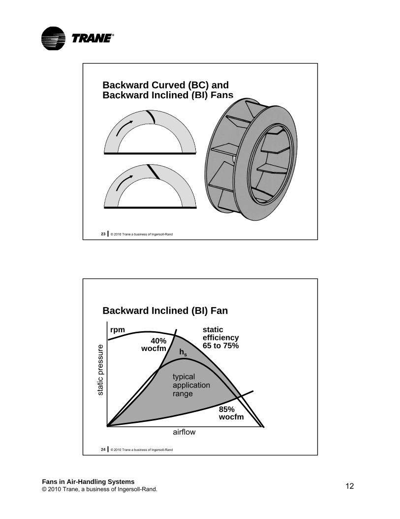
Backward Curved (BC) and Backward Inclined (BI) Fans
© 2010 Trane a business of Ingersoll-Rand24
Backward Inclined (BI) Fan
40%wocfm
85%wocfm
airflow
stat
ic p
ress
ure
typicalapplicationrange
static efficiency65 to 75%
hs
rpm

Fans in Air-Handling Systems© 2010 Trane, a business of Ingersoll-Rand. 13
© 2010 Trane a business of Ingersoll-Rand25
Airfoil (AF) Fan
© 2010 Trane a business of Ingersoll-Rand26
Airfoil (AF) Fan
50%wocfm
85%wocfm
airflow
stat
ic p
ress
ure
typicalapplicationrange
static efficiency80 to 85%hs
rpm

Fans in Air-Handling Systems© 2010 Trane, a business of Ingersoll-Rand. 14
© 2010 Trane a business of Ingersoll-Rand27
Impact of Blade Shape on Fan Input Power
Fan type and Input power, Rotational speed, wheel diameter bhp rpm
Housed FC, 25 in. 13.0 775
Housed AF, 25 in. 11.8 1320
Based on a typical VAV air-handling unit configuration (OA/RA mixing box, high-efficiency filter, hot-water heating coil, chilled-water cooling coil, and draw-thru supply fan with a single discharge opening off the fan section) operating at 13,000 cfm and a 3.8 in. H2O total static pressure drop.
© 2010 Trane a business of Ingersoll-Rand28
summary
Shape of Fan Blades
FC fans are typically the lowest cost and are often the most forgiving (wide application range, less severe surge characteristics)• Very popular in packaged units and light commercial
equipment, where less attention is given to duct connections and layout
AF fans are typically the most efficient, but require more attention to avoid surge• More common in larger packaged rooftops and air-
handling units, where more attention is given to proper duct connections and layout

Fans in Air-Handling Systems© 2010 Trane, a business of Ingersoll-Rand. 15
© 2010 Trane a business of Ingersoll-Rand29
Housed Versus Unhoused
housed centrifugal fan unhoused centrifugal(plenum) fan
© 2010 Trane a business of Ingersoll-Rand30
Direct-Drive Plenum Fan

Fans in Air-Handling Systems© 2010 Trane, a business of Ingersoll-Rand. 16
© 2010 Trane a business of Ingersoll-Rand31
AHU with a housed centrifugal fan(single front discharge opening)
AHU with an unhoused centrifugal (plenum) fan(single front discharge opening)
© 2010 Trane a business of Ingersoll-Rand32
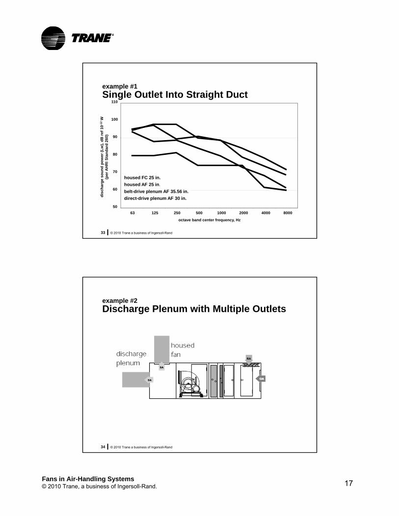
example #1
Single Outlet Into Straight DuctFan type and Input power, Rotational speed,wheel diameter bhp rpm
Housed FC, 25 in. 13.0 775
Housed AF, 25 in. 11.8 1320
Belt-drive plenum AF, 35.56 in. 14.0 1050
Direct-drive plenum AF, 30 in. 12.8 1320
Based on a typical VAV air-handling unit configuration (OA/RA mixing box, high-efficiency filter, hot-water heating coil, chilled-water cooling coil, and draw-thru supply fan with a single discharge opening off the fan section) operating at 13,000 cfm and 2 in. H2O of external static pressure drop.
Fans in Air-Handling Systems© 2010 Trane, a business of Ingersoll-Rand. 17
© 2010 Trane a business of Ingersoll-Rand33
example #1
Single Outlet Into Straight Duct
50
60
70
80
90
100
110
63 125 250 500 1000 2000 4000 8000
housed FC 25 in.
housed AF 25 in.
belt-drive plenum AF 35.56 in.
direct-drive plenum AF 30 in.
dis
char
ge
sou
nd
po
wer
(L
w),
dB
ref
10
-12
W(p
er
AH
RI
Sta
nd
ard
26
0)
octave band center frequency, Hz
© 2010 Trane a business of Ingersoll-Rand34
example #2
Discharge Plenum with Multiple Outlets
Fans in Air-Handling Systems© 2010 Trane, a business of Ingersoll-Rand. 18
© 2010 Trane a business of Ingersoll-Rand35
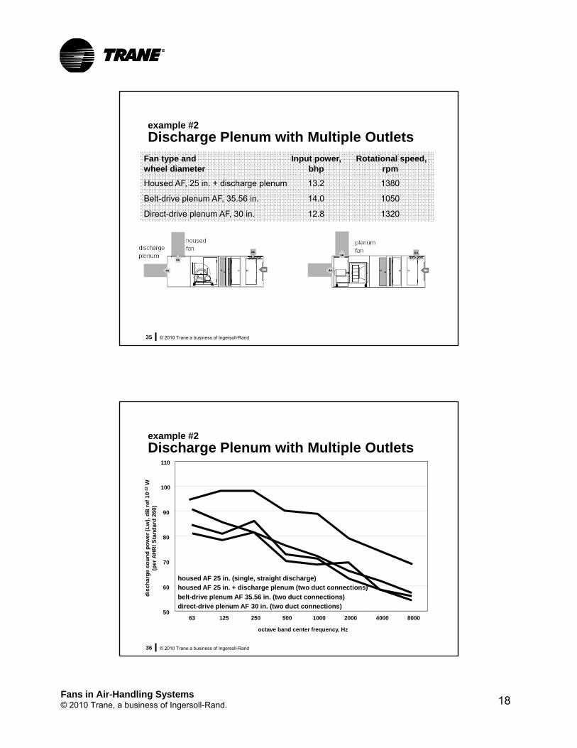
example #2
Discharge Plenum with Multiple OutletsFan type and Input power, Rotational speed, wheel diameter bhp rpm
Housed AF, 25 in. + discharge plenum 13.2 1380
Belt-drive plenum AF, 35.56 in. 14.0 1050
Direct-drive plenum AF, 30 in. 12.8 1320
© 2010 Trane a business of Ingersoll-Rand36
example #2
Discharge Plenum with Multiple Outlets
50
60
70
80
90
100
110
63 125 250 500 1000 2000 4000 8000
belt-drive plenum AF 35.56 in. (two duct connections)
direct-drive plenum AF 30 in. (two duct connections)
housed AF 25 in. (single, straight discharge)housed AF 25 in. + discharge plenum (two duct connections)
dis
char
ge
sou
nd
po
wer
(L
w),
dB
ref
10
-12
W(p
er
AH
RI
Sta
nd
ard
26
0)
octave band center frequency, Hz
Fans in Air-Handling Systems© 2010 Trane, a business of Ingersoll-Rand. 19
© 2010 Trane a business of Ingersoll-Rand37
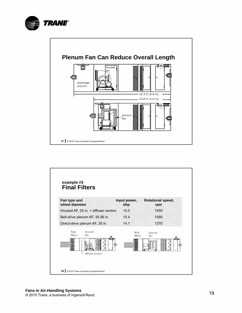
Plenum Fan Can Reduce Overall Length
© 2010 Trane a business of Ingersoll-Rand38
example #3
Final Filters
Fan type and Input power, Rotational speed, wheel diameter bhp rpm
Housed AF, 25 in. + diffuser section 15.0 1450
Belt-drive plenum AF, 35.56 in. 15.4 1090
Direct-drive plenum AF, 30 in. 14.1 1370
Fans in Air-Handling Systems© 2010 Trane, a business of Ingersoll-Rand. 20
© 2010 Trane a business of Ingersoll-Rand39
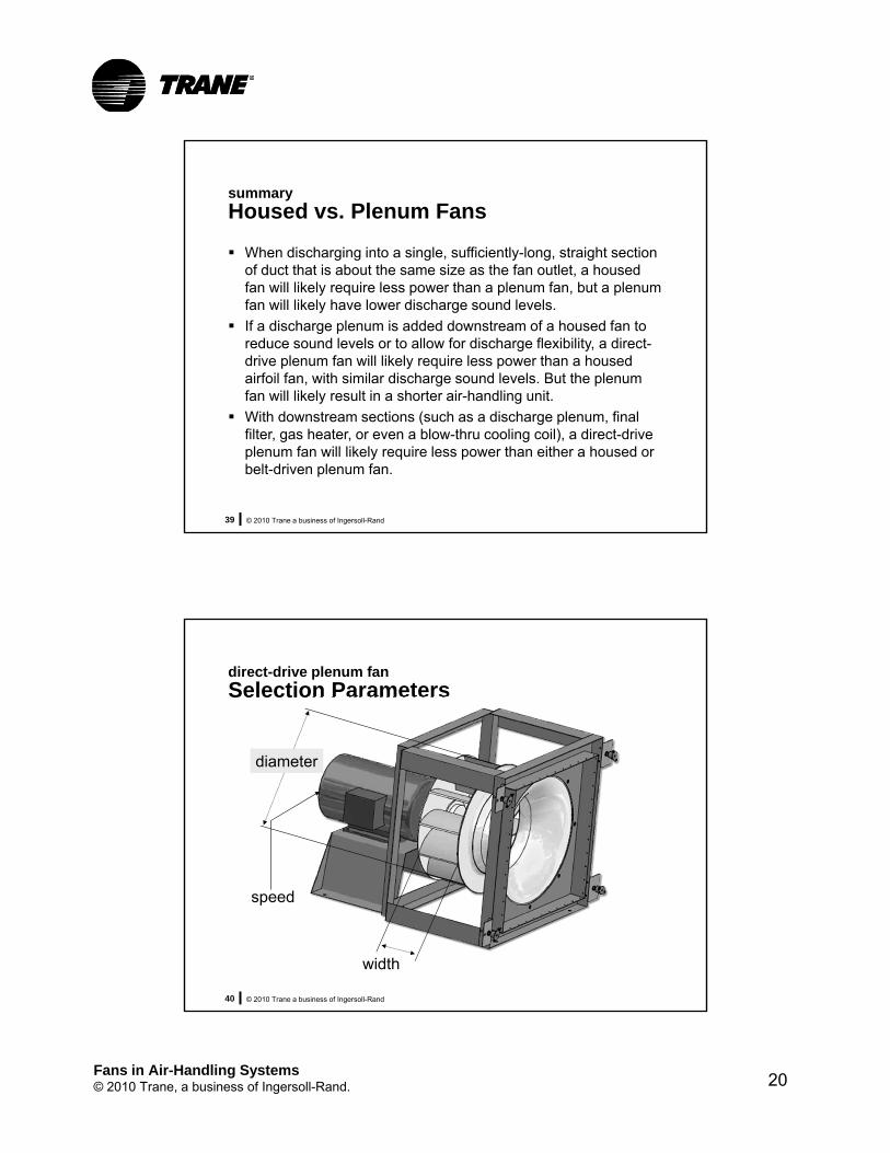
summary
Housed vs. Plenum Fans
When discharging into a single, sufficiently-long, straight section of duct that is about the same size as the fan outlet, a housed fan will likely require less power than a plenum fan, but a plenum fan will likely have lower discharge sound levels.
If a discharge plenum is added downstream of a housed fan to reduce sound levels or to allow for discharge flexibility, a direct-drive plenum fan will likely require less power than a housed airfoil fan, with similar discharge sound levels. But the plenum fan will likely result in a shorter air-handling unit.
With downstream sections (such as a discharge plenum, final filter, gas heater, or even a blow-thru cooling coil), a direct-drive plenum fan will likely require less power than either a housed or belt-driven plenum fan.
© 2010 Trane a business of Ingersoll-Rand40
direct-drive plenum fan
Selection Parameters
diameter
width
speed

Fans in Air-Handling Systems© 2010 Trane, a business of Ingersoll-Rand. 21
© 2010 Trane a business of Ingersoll-Rand41
Flexible-Speed Selection
Synchronous Speed Fan speed (rpm)
is held constant Wheel diameter and
width are varied
Flexible Speed Fan wheel width
is held constant Wheel diameter and
speed are varied• Trane VFDs and motors can
operate to at least 90 Hz
Flexible-speed DDP fan selections are typically more efficient and quieter than synchronous-speed selections.
© 2010 Trane a business of Ingersoll-Rand42
example
Flexible-Speed Selection
Fan type and Wheel width, Fan rpm Motor speed, Input power, wheel diameter % of nominal rpm bhp
Direct-drive plenum AF, 30 in. 57% 1780 1800 15.4(synchronous-speed selection)
Direct-drive plenum AF, 30 in. 100% 1320 1200 12.8(flexible-speed selection)

Fans in Air-Handling Systems© 2010 Trane, a business of Ingersoll-Rand. 22
© 2010 Trane a business of Ingersoll-Rand43
example
Flexible-Speed Selection
50
60
70
80
90
100
110
63 125 250 500 1000 2000 4000 8000
octave band center frequency, Hz
direct-drive plenum AF 30 in. (synchronous-speed selection)
direct-drive plenum AF 30 in. (flexible-speed selection)
dis
char
ge
sou
nd
po
wer
(L
w),
dB
ref
10
-12
W(p
er
AH
RI
Sta
nd
ard
26
0)
© 2010 Trane a business of Ingersoll-Rand44
Multiple Fans (Fan Array)
upstream (inlet) side downstream (outlet) side
Fans in Air-Handling Systems© 2010 Trane, a business of Ingersoll-Rand. 23
© 2010 Trane a business of Ingersoll-Rand45
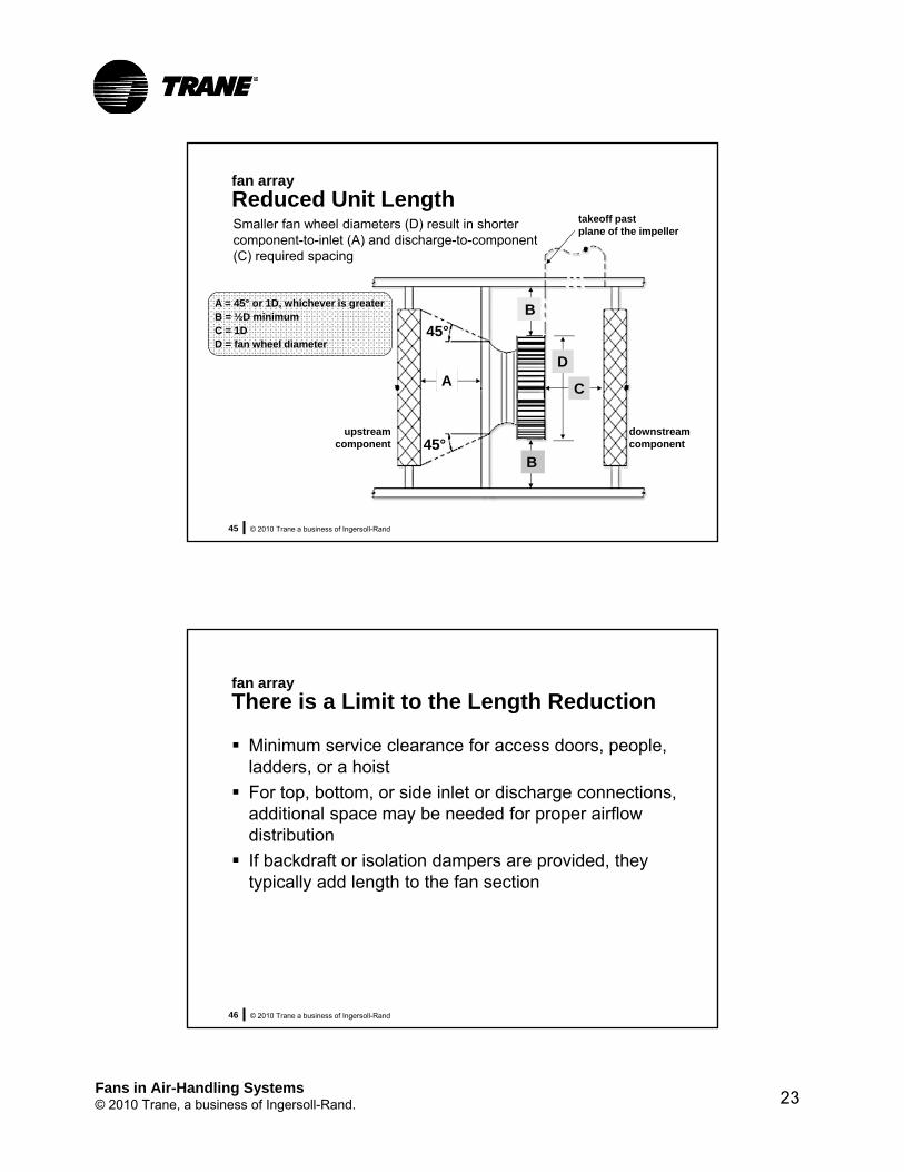
fan array
Reduced Unit Lengthtakeoff past plane of the impeller
upstream component
A C
D
B
B
45°
45°
downstream component
Smaller fan wheel diameters (D) result in shorter component-to-inlet (A) and discharge-to-component (C) required spacing
A = 45° or 1D, whichever is greaterB = ½D minimumC = 1DD = fan wheel diameter
© 2010 Trane a business of Ingersoll-Rand46
fan array
There is a Limit to the Length Reduction
Minimum service clearance for access doors, people, ladders, or a hoist
For top, bottom, or side inlet or discharge connections, additional space may be needed for proper airflow distribution
If backdraft or isolation dampers are provided, they typically add length to the fan section

Fans in Air-Handling Systems© 2010 Trane, a business of Ingersoll-Rand. 24
© 2010 Trane a business of Ingersoll-Rand47
example length reduction
Single Fan Versus Fan Array
Upstream Upstream UpstreamQty Diameter, spacing req’d, service clear, total,
in. in. in. in.
1 33 19.8 12 19.8
2 24.5 14.7 12 14.7
3 20 12.0 12 12.0
4 18.75 11.0 12 12.0
© 2010 Trane a business of Ingersoll-Rand48
example length reduction
Single Fan Versus Fan Array
Downstream Length of Downstream Downstream Qty Diameter, spacing req’d, fan + motor, service clear, total,
in. in. in. in. in.
1 33 50.5 54.3 0 54.3
2 24.5 38.8 42.0 0 42.0
3 20 33.1 35.3 18 53.3
4 18.75 29.9 31.4 18 49.4
+
+
+
+

Fans in Air-Handling Systems© 2010 Trane, a business of Ingersoll-Rand. 25
© 2010 Trane a business of Ingersoll-Rand49
AHU fan section with single fan wheel
AHU fan section with two fan wheels
19.8 + 54.3 = 74.1 in.
14.7 + 42.0 = 56.7 in.
AHU fan section with three fan wheels
12.0 + 53.3 = 65.3 in.
AHU fan section with four fan wheels
12.0 + 49.4 = 61.4 in.
© 2010 Trane a business of Ingersoll-Rand50
example
Providing Redundancy with a Fan ArrayQty Level of Airflow Input power Input power Motor size
running Diameter, redundancy (each fan), (each fan), (total), (each fan),
in. cfm bhp bhp hp
2 24.5 Design 7500 6.55 13.10 7.5
1 24.5 100% 15000 16.13 16.13 20 (change from 7.5 to 20 hp motors)
1 24.5 70% 10500 7.13 7.13 7.5 (no change in motor sizes)

Fans in Air-Handling Systems© 2010 Trane, a business of Ingersoll-Rand. 26
© 2010 Trane a business of Ingersoll-Rand51
example
Providing Redundancy with a Fan ArrayQty Level of Airflow Input power Input power Motor size
running Diameter, redundancy (each fan), (each fan), (total), (each fan),
in. cfm bhp bhp hp
2 24.5 Design 7500 6.55 13.10 7.5
1 24.5 100% 15000 16.13 16.13 20 (change from 7.5 to 20 hp motors)
1 24.5 70% 10500 7.13 7.13 7.5 (no change in motor sizes)
Qty Level of Airflow Input power Input power Motor sizerunning Diameter, redundancy (each fan), (each fan), (total), (each fan),
in. cfm bhp bhp hp
3 20 Design 5000 4.68 14.04 7.5
2 20 100% 7500 7.43 14.86 7.5 (no change in motor sizes)
Qty Level of Airflow Input power Input power Motor sizerunning Diameter, redundancy (each fan), (each fan), (total), (each fan),
in. cfm bhp bhp hp
4 18.25 Design 3750 3.53 14.12 5
3 18.25 100% 5000 4.71 14.13 5 (no change in motor sizes)
© 2010 Trane a business of Ingersoll-Rand52
Providing Redundancy with a Fan Array
Two fans can often provide 100% redundancy and results in the lowest total power when all fans are operating, but may require larger fan motors to be provided.• If less than 100% is acceptable, two fans may not need
to increase motor sizes.
Three or four fans can typically provide 100% redundancy without significant changes in motor size.
Fans in Air-Handling Systems© 2010 Trane, a business of Ingersoll-Rand. 27
© 2010 Trane a business of Ingersoll-Rand53
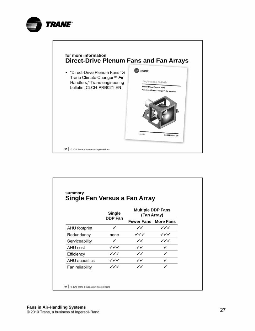
for more information
Direct-Drive Plenum Fans and Fan Arrays
“Direct-Drive Plenum Fans for Trane Climate Changer™ Air Handlers,” Trane engineering bulletin, CLCH-PRB021-EN
© 2010 Trane a business of Ingersoll-Rand54
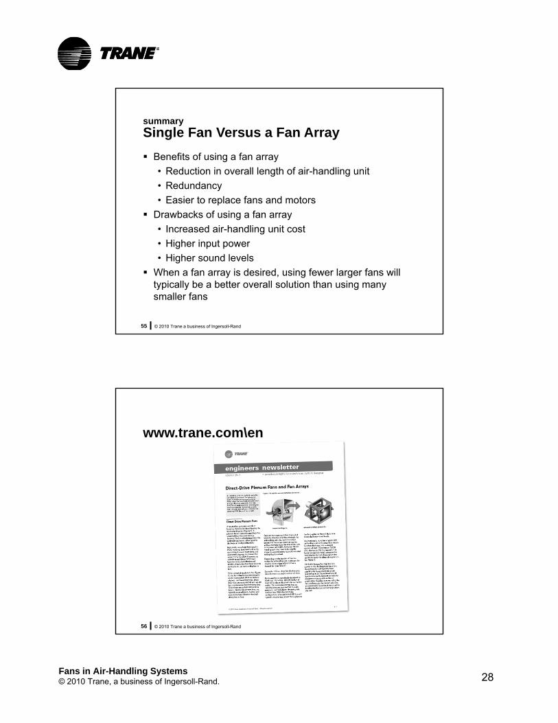
summary
Single Fan Versus a Fan Array
Fan reliability
Multiple DDP Fans(Fan Array)Single
DDP FanMore FansFewer Fans
AHU footprint
noneRedundancy
AHU cost
AHU acoustics
Efficiency
Serviceability
Fans in Air-Handling Systems© 2010 Trane, a business of Ingersoll-Rand. 28
© 2010 Trane a business of Ingersoll-Rand55
summary
Single Fan Versus a Fan Array
Benefits of using a fan array
• Reduction in overall length of air-handling unit
• Redundancy
• Easier to replace fans and motors
Drawbacks of using a fan array
• Increased air-handling unit cost
• Higher input power
• Higher sound levels
When a fan array is desired, using fewer larger fans will typically be a better overall solution than using many smaller fans
© 2010 Trane a business of Ingersoll-Rand56
www.trane.com\en

Fans in Air-Handling Systems© 2010 Trane, a business of Ingersoll-Rand. 29
Fans in Air-Handling Systems
Impact of System Configuration on Fan
Selection
© 2010 Trane a business of Ingersoll-Rand58
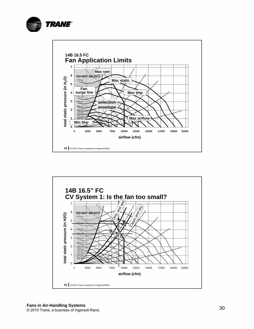
constant volume (CV)
Basic System
EA
RA
SAOA
spacespace
MA
T
constant-speed fan
a size 14 unit with a 16.5 FC fan might work
CC
9,000 cfm
Pressure drops @ 9,000 cfm/7,500 cfm
Device Low High
SA duct 2.0 2.0
RA duct 0.5 0.5
MERV13 0.4 1.2
Coil 0.6 0.9
Total 3.5 4.6
7,500 cfm
1,500 cfm
1,500 cfm
Fans in Air-Handling Systems© 2010 Trane, a business of Ingersoll-Rand. 30
© 2010 Trane a business of Ingersoll-Rand59
7
6
5
4
3
2
1
0
0 2500 5000 7500 10000 12500 15000 17500 20000 22500
airflow (cfm)
tota
l sta
tic
pre
ssu
re (
in H
2O
)
1500 rpm
1400 rpm
1100 rpm
1300 rpm
1200 rpm
1000 rpm
800 rpm
900 rpm
700 rpm
600 rpm
500 rpm
1.00
bh
p
1.50
bh
p
3.00
bh
p
5.00
bh
p
7.00
bh
p
10.0
0 b
hp
DO NOT SELECT
14B 16.5 FC
Fan Application Limits
selectionenvelope
Min bhp
Fan surge line
Max rpm
Max static
Max bhp
Max airflow
© 2010 Trane a business of Ingersoll-Rand60
0 2500 5000 7500 10000 12500 15000 17500 20000 22500
airflow (cfm)
tota
l sta
tic
pre
ssu
re (
in H
2O)
1500 rpm
1400 rpm
1100 rpm
1300 rpm
1200 rpm
1000 rpm
800 rpm
900 rpm
700 rpm
600 rpm
500 rpm
1.00
bhp
1.50
bhp
3.00
bhp
5.00
bhp
7.00
bhp
10.0
0 bh
p
DO NOT SELECT
14B 16.5” FCCV System 1: Is the fan too small?
AB
DC
7
6
5
4
3
2
1
0

Fans in Air-Handling Systems© 2010 Trane, a business of Ingersoll-Rand. 31
© 2010 Trane a business of Ingersoll-Rand61
0 2500 5000 7500 10000 12500 15000 17500 20000 22500
airflow (cfm)
tota
l sta
tic
pre
ssu
re (
in H
2O)
1500 rpm
1400 rpm
1100 rpm
1300 rpm
1200 rpm
1000 rpm
800 rpm
900 rpm
700 rpm
600 rpm
500 rpm
1.00
bhp
1.50
bhp
3.00
bhp
5.00
bhp
7.00
bhp
10.0
0 bh
p
DO NOT SELECT
7
6
5
4
3
2
1
0
14B 16.5 FCCV System 2: Is the fan too big?
C
A
B
© 2010 Trane a business of Ingersoll-Rand62
EA
Multiple-Zone VAV With Relief Fan
spacespace
spacespace
RA
OA SA
EA
MA
T
T
variable-speed fan
T
supply air temp determines AHU cooling capacity
9,000 cfm
7,500 cfm
1,500 cfm
1,500 cfm

Fans in Air-Handling Systems© 2010 Trane, a business of Ingersoll-Rand. 32
© 2010 Trane a business of Ingersoll-Rand63
Static Pressure Drops At 9,000 cfm supply airflow
At 7,500 cfm return airflow
Assume path throughzone 1 has higheststatic pressure loss
Device Low High
RA plen 0.5 0.5
RA duct 0.2 0.2
RA damp 0.2 0.2
MERV13 0.4 1.2
Coil 0.6 0.9
SA duct 2.0 2.0
VAV box 1 0.4 0.4
Runout 1 0.4 0.4
Total 4.7 5.8
© 2010 Trane a business of Ingersoll-Rand64
15.0
12.5
10.0
7.5
5.0
2.5
00 2500 5000 7500 10000 12500 15000
airflow (cfm)
tota
l sta
tic
pre
ss
ure
(in
H2
O)
E14 draw-thru; 18-inch AF; without inlet vanes
3100 RPM
3000 RPM
2800 RPM
2600 RPM
2400 RPM
2200 RPM
2000 RPM
1800 RPM
1600 RPM
1400 RPM
1200 RPM
1000 RPM800 RPM
40 %WO
50 %WO
60 %WO
70 %WO
80 %WO
90 %WO
A
DO NOT SELECT
B
Fans in Air-Handling Systems© 2010 Trane, a business of Ingersoll-Rand. 33
© 2010 Trane a business of Ingersoll-Rand65
15.0
12.5
10.0
7.5
5.0
2.5
00 2500 5000 7500 10000 12500 15000
airflow (cfm)
tota
l sta
tic
pre
ss
ure
(in
H2
O)
E14 draw-thru; 18-inch AF; without inlet vanes
3100 RPM
3000 RPM
2800 RPM
2600 RPM
2400 RPM
2200 RPM
2000 RPM
1800 RPM
1600 RPM
1400 RPM
1200 RPM
1000 RPM800 RPM
40 %WO
50 %WO
60 %WO
70 %WO
80 %WO
90 %WO
A
DO NOT SELECT
Ps = Pc + (Pd - Pc)*(Q/Qd)^2
Ps = 1.3 + (5.8-1.3)*(5000/9000)^2
Ps = 2.7
B
© 2010 Trane a business of Ingersoll-Rand66
15.0
12.5
10.0
7.5
5.0
2.5
00 2500 5000 7500 10000 12500 15000
airflow (cfm)
tota
l sta
tic
pre
ss
ure
(in
H2
O)
E14 draw-thru; 18-inch AF; without inlet vanes
3100 RPM
3000 RPM
2800 RPM
2600 RPM
2400 RPM
2200 RPM
2000 RPM
1800 RPM
1600 RPM
1400 RPM
1200 RPM
1000 RPM800 RPM
40 %WO
50 %WO
60 %WO
70 %WO
80 %WO
90 %WO
A
11.5
4.5
2.7
5.8
1.3
DO NOT SELECT
Ps = Pc + (Pd - Pc)*(Q/Qd)^2
Ps = 1.3 + (5.8-1.3)*(5000/9000)^2
Ps = 2.7

Fans in Air-Handling Systems© 2010 Trane, a business of Ingersoll-Rand. 34
© 2010 Trane a business of Ingersoll-Rand67
15.0
12.5
10.0
7.5
5.0
2.5
00 2500 5000 7500 10000 12500 15000
airflow (cfm)
tota
l sta
tic
pre
ss
ure
(in
H2
O)
E14 draw-thru; 18-inch AF; without inlet vanes
3100 RPM
3000 RPM
2800 RPM
2600 RPM
2400 RPM
2200 RPM
2000 RPM
1800 RPM
1600 RPM
1400 RPM
1200 RPM
1000 RPM800 RPM
40 %WO
50 %WO
60 %WO
70 %WO
80 %WO
90 %WO
DO NOT SELECT
© 2010 Trane a business of Ingersoll-Rand68
15.0
12.5
10.0
7.5
5.0
2.5
00 2500 5000 7500 10000 12500 15000
airflow (cfm)
tota
l sta
tic
pre
ss
ure
(in
H2
O)
E14 draw-thru; 18-inch AF; without inlet vanes
3100 RPM
3000 RPM
2800 RPM
2600 RPM
2400 RPM
2200 RPM
2000 RPM
1800 RPM
1600 RPM
1400 RPM
1200 RPM
1000 RPM800 RPM
40 %WO
50 %WO
60 %WO
70 %WO
80 %WO
90 %WO
DO NOT SELECT
A
B

Fans in Air-Handling Systems© 2010 Trane, a business of Ingersoll-Rand. 35
© 2010 Trane a business of Ingersoll-Rand69
15.0
12.5
10.0
7.5
5.0
2.5
00 2500 5000 7500 10000 12500 15000
airflow (cfm)
tota
l sta
tic
pre
ss
ure
(in
H2
O)
E14 draw-thru; 18-inch AF; without inlet vanes
3100 RPM
3000 RPM
2800 RPM
2600 RPM
2400 RPM
2200 RPM
2000 RPM
1800 RPM
1600 RPM
1400 RPM
1200 RPM
1000 RPM800 RPM
40 %WO
50 %WO
60 %WO
70 %WO
80 %WO
90 %WO
A
DO NOT SELECT
B
© 2010 Trane a business of Ingersoll-Rand70
15.0
12.5
10.0
7.5
5.0
2.5
00 2500 5000 7500 10000 12500 15000
airflow (cfm)
tota
l sta
tic
pre
ss
ure
(in
H2
O)
E14 draw-thru; 18-inch AF; without inlet vanes
3100 RPM
3000 RPM
2800 RPM
2600 RPM
2400 RPM
2200 RPM
2000 RPM
1800 RPM
1600 RPM
1400 RPM
1200 RPM
1000 RPM800 RPM
40 %WO
50 %WO
60 %WO
70 %WO
80 %WO
90 %WO
Morning warm-up operation
A
B
C
DO NOT SELECT

Fans in Air-Handling Systems© 2010 Trane, a business of Ingersoll-Rand. 36
© 2010 Trane a business of Ingersoll-Rand71
EA
Multiple-Zone VAV with Return Fan
spacespace
spacespace
RA
OA SA
EA
MA
T
T
variable-speed fan
7,500 cfm0 cfm
1,500 cfm
Design
1,500 cfm
6,000 cfm
8,000 cfm8,000 cfm
6,000 cfm
2,000 cfm
0 cfm
0 cfm
0 cfm
??? cfm
??? cfm
EconomizerMorning warm up
9,000 cfm
System Effect

Fans in Air-Handling Systems© 2010 Trane, a business of Ingersoll-Rand. 37
© 2010 Trane a business of Ingersoll-Rand73
Developing a Uniform Velocity Profile
uniformvelocityprofile
fan
© 2010 Trane a business of Ingersoll-Rand74
Common System Effects
Elbow, branch, turning vanes, or damper located too close to the fan outlet
Elbow, turning vanes, air straightener, or other obstruction located too close to the fan inlet
Pre-swirling the air prior to it entering the fan wheel
Use of an inlet plenum or cabinet

Fans in Air-Handling Systems© 2010 Trane, a business of Ingersoll-Rand. 38
© 2010 Trane a business of Ingersoll-Rand75
AMCA Publication 201, Fans and Systems
Prediction of common System Effect Factors
© 2010 Trane a business of Ingersoll-Rand76
example
System Effect
Source: Air Movement and Control Association. 2002. Fans and Systems, Publication 201. Arlington Heights, IL: AMCA.
Position D
Position C
Position B
Position Ainlet

Fans in Air-Handling Systems© 2010 Trane, a business of Ingersoll-Rand. 39
© 2010 Trane a business of Ingersoll-Rand77
example
System Effect
100% Effective Duct Length
2.5 duct diameters for 2500 fpm (or less)
Add 1 duct diameter for each additional 1000 fpm
Source: Air Movement and Control Association. 2002. Fans and Systems, Publication 201. Arlington Heights, IL: AMCA.
25%
50%
75%
100% effective duct length
blast area outlet area discharge duct
Centrifugal
fan
© 2010 Trane a business of Ingersoll-Rand78
Example
Source: Air Movement and Control Association. 2002. Fans and Systems, Publication 201. Arlington Heights, IL: AMCA.

Fans in Air-Handling Systems© 2010 Trane, a business of Ingersoll-Rand. 40
© 2010 Trane a business of Ingersoll-Rand79
Source: Air Movement and Control Association. 2002. Fans and Systems, Publication 201. Arlington Heights, IL: AMCA.
© 2010 Trane a business of Ingersoll-Rand80
3.0
2.5
2.0
1.5
1.0
0.5
0.0
tota
l st
atic
pre
ssu
re (
in H
2O)
14A Draw-thru; 18.25-inch FC; without inlet vanes
0 2500 5000 7500 10000 12500 15000
airflow
system effect factor15.3 bhp, 800 rpm
9000 cfm
1.8 in.
2.25 in.6.1 bhp, 875 rpm 2
942 RPM
600 RPM
500 RPM
25 %WO 50 %WO
60 %WO
70 %WO
7.5
0 b
hp
5.0
0 b
hp
3.5
0 b
hp

Fans in Air-Handling Systems© 2010 Trane, a business of Ingersoll-Rand. 41
Fans in Air-Handling Systems
Fan Acoustics
© 2010 Trane a business of Ingersoll-Rand82
Propeller Fans
Reduce propeller fan sound by• Choosing the low noise fan option
• Attenuating the path
Fans in Air-Handling Systems© 2010 Trane, a business of Ingersoll-Rand. 42
© 2010 Trane a business of Ingersoll-Rand83
Fan Sound
Sound generation is influenced by• Fan type
• Flow rate
• Total pressure
• Efficiency
• Flow into and out of the fan
© 2010 Trane a business of Ingersoll-Rand84
AHRI 260
Includes unit impact on fan sound• Negative flow impacts
• Benefits of plenums and lining
Provides for “apples to apples” comparison

Fans in Air-Handling Systems© 2010 Trane, a business of Ingersoll-Rand. 43
© 2010 Trane a business of Ingersoll-Rand85
AHRI 260
See Sound Ratings and ARI Standard 260 newsletter for additional information
© 2010 Trane a business of Ingersoll-Rand86
Selection Program
Provides a convenient way to access sound data
Shows acoustical impact of• Changing operating point
• Changing fan type
Fans in Air-Handling Systems© 2010 Trane, a business of Ingersoll-Rand. 44
© 2010 Trane a business of Ingersoll-Rand87
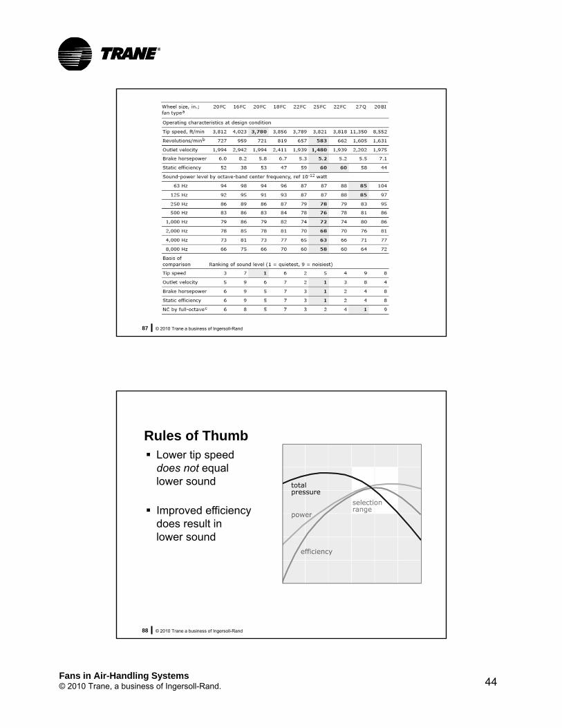
© 2010 Trane a business of Ingersoll-Rand88
Rules of Thumb Lower tip speed
does not equal lower sound
Improved efficiency does result in lower sound

Fans in Air-Handling Systems© 2010 Trane, a business of Ingersoll-Rand. 45
© 2010 Trane a business of Ingersoll-Rand89
stat
ic p
ress
ure
volumetric flow rate
90% WO
80% WO
70% WO
60% WO
50% WO40% WO30% WO
Constant Speed CurveAcoustic Stall
Acoustic predictions
possible
High level unstable acoustics
© 2010 Trane a business of Ingersoll-Rand90
volumetric flow rate
Constant Speed Curve
Acoustic Stall
Acoustic predictions
possible
High level unstable acoustics
VAV Modulation Curve
Note that as unit modulates down can enter the unstable region
Design point is in stable region
90% WO
80% WO
60% WO
50% WO40% WO30% WO
stat
ic p
ress
ure

Fans in Air-Handling Systems© 2010 Trane, a business of Ingersoll-Rand. 46
© 2010 Trane a business of Ingersoll-Rand91
Selection tips
Accurate sound data is a must
Review all fan and unit options
Avoid “rules-of-thumb”
Fans in Air-Handling Units
Common Problems:
Not Delivering Enough Airflow

Fans in Air-Handling Systems© 2010 Trane, a business of Ingersoll-Rand. 47
© 2010 Trane a business of Ingersoll-Rand93
Fan System Problems
Most common complaints• Insufficient airflow
• Excessive noise/vibration
Common causes for insufficient airflow• Underestimated system resistance
• Poor accounting for system effect
• Unanticipated installation modifications
• Hence, poor fan selection
© 2010 Trane a business of Ingersoll-Rand94
AMCA 201“Fans and Systems”
Lists possible causes for low flow, including:• Improper inlet duct design
• Improper outlet duct design
• Improper fan installation
• Unexpected system resistance characteristics
• Improper allowance for fan system effect
• Dirty filters, ducts, coils
• “Performance” determined using uncertain field measurement techniques
Includes much help for system effect corrections

Fans in Air-Handling Systems© 2010 Trane, a business of Ingersoll-Rand. 48
© 2010 Trane a business of Ingersoll-Rand95
AMCA 202 “Troubleshooting”
Lists possible causes for low airflow, including: • Improper fan installation or assembly
• Damage in handling or transit
• System design error
• Deterioration of system
• Faulty controls
• Poor fan selection
Includes detailed troubleshooting checklists
© 2010 Trane a business of Ingersoll-Rand96
AMCA 203“Field Performance Measurement of Fan Systems”
Your duct system?
Fans in Air-Handling Systems© 2010 Trane, a business of Ingersoll-Rand. 49
Fans in Air-Handling Units
Common Problems: Too Much Noise
© 2010 Trane a business of Ingersoll-Rand98
Causes of Noise
Fan / unit defect
Acoustics ignored during selection
Duct system flow problems
Fans in Air-Handling Systems© 2010 Trane, a business of Ingersoll-Rand. 50
© 2010 Trane a business of Ingersoll-Rand99
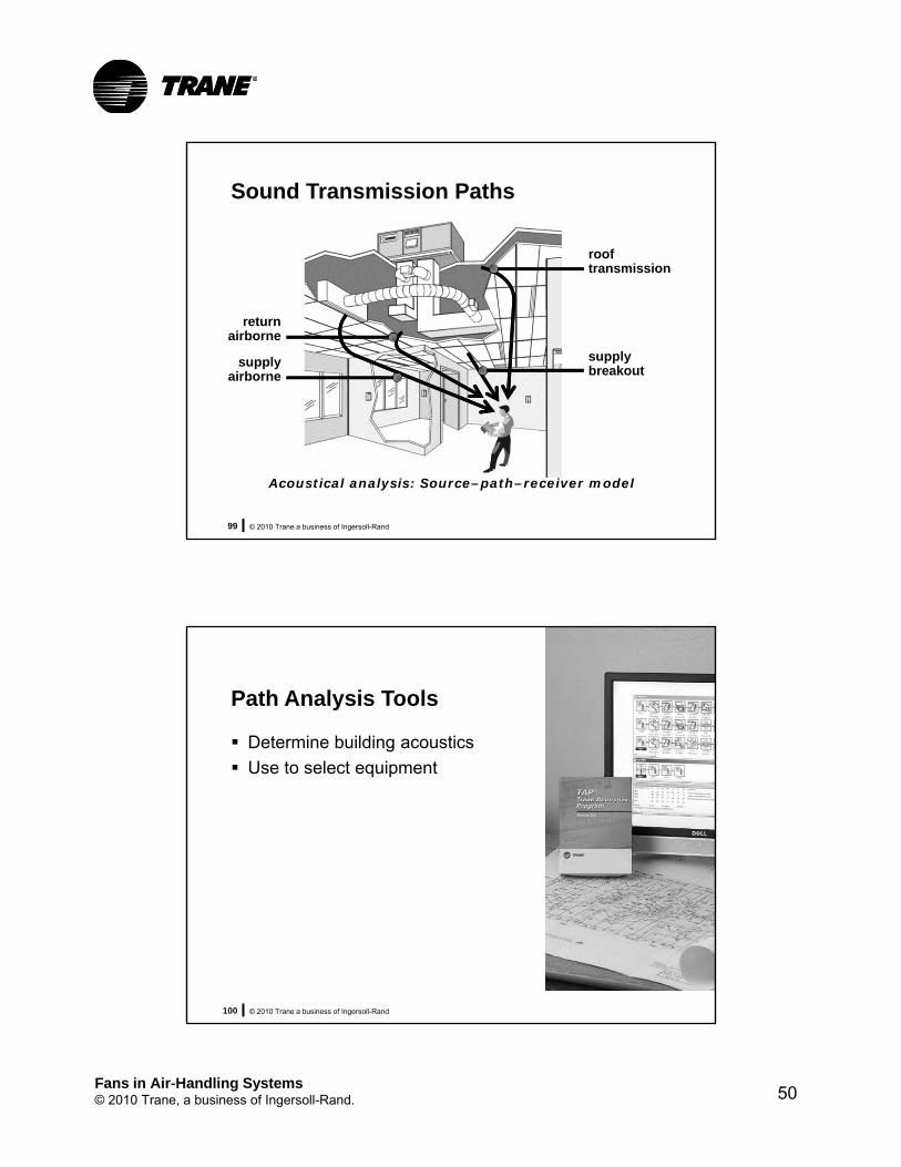
Sound Transmission Paths
rooftransmission
supplybreakout
returnairborne
supplyairborne
Acoustical analysis: Source–path–receiver model
© 2010 Trane a business of Ingersoll-Rand100
Path Analysis Tools
Determine building acoustics
Use to select equipment

Fans in Air-Handling Systems© 2010 Trane, a business of Ingersoll-Rand. 51
© 2010 Trane a business of Ingersoll-Rand101
Duct Design
ASHRAE algorithms
Available for common duct components
Used to predict acoustic impact
© 2010 Trane a business of Ingersoll-Rand102
Duct Design
Poor design creates turbulence
Turbulence generates low frequency noise
Low frequency sound• Passes through ducts
• Moves lightweight components
Fans in Air-Handling Systems© 2010 Trane, a business of Ingersoll-Rand. 52
© 2010 Trane a business of Ingersoll-Rand103
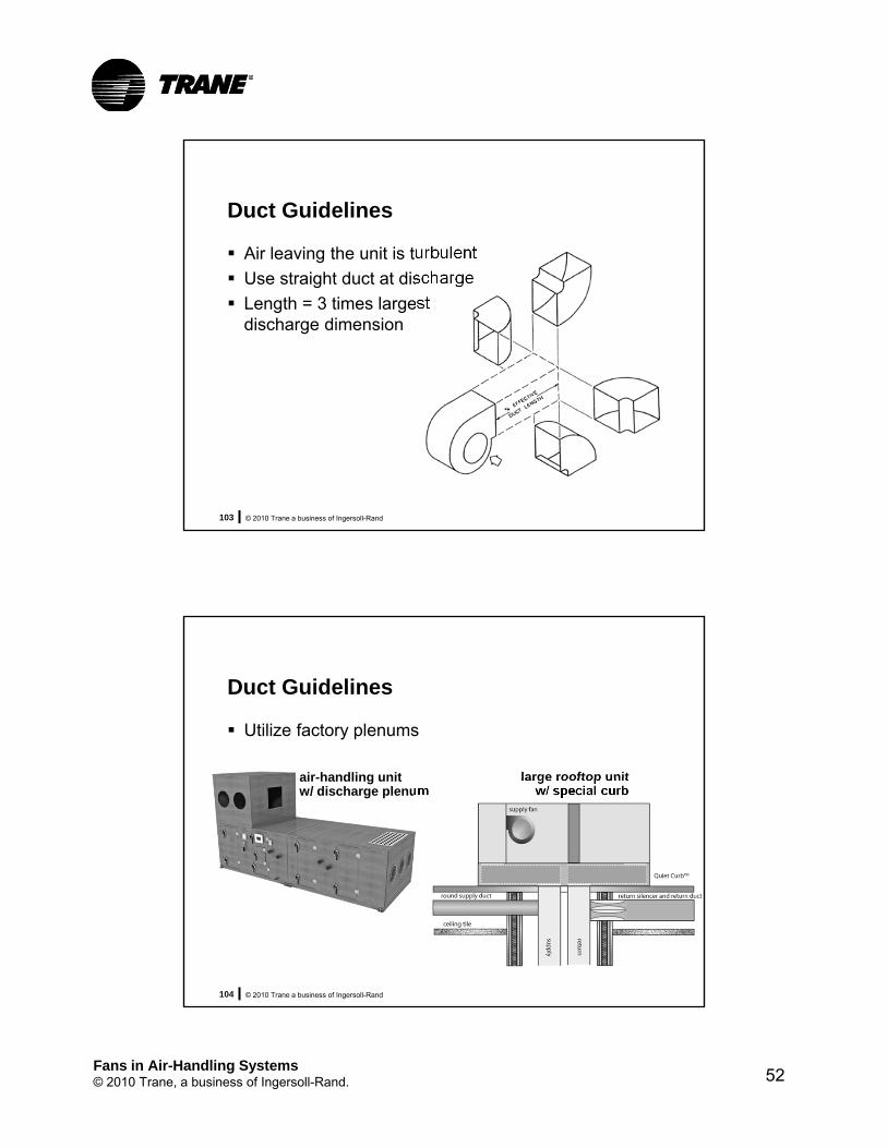
Duct Guidelines
Air leaving the unit is turbulent
Use straight duct at discharge
Length = 3 times largest discharge dimension
© 2010 Trane a business of Ingersoll-Rand104
Duct Guidelines
Utilize factory plenums
air-handling unitw/ discharge plenum
large rooftop unitw/ special curb

Fans in Air-Handling Systems© 2010 Trane, a business of Ingersoll-Rand. 53
© 2010 Trane a business of Ingersoll-Rand105
Duct Guidelines
Avoid close coupled fittings
noisiest better
15° max.
15° max.
quietest
Source: A Practical Guide To Noise and Vibration Control For HVAC Systems, ASHRAE, 1991. Figure 1-23
© 2010 Trane a business of Ingersoll-Rand106
Summary
Successful acoustics requires• Building analysis
• Equipment selection
• Duct design
Fans in Air-Handling Systems© 2010 Trane, a business of Ingersoll-Rand. 54
ASHRAE 90.1 Requirements
© 2010 Trane a business of Ingersoll-Rand108
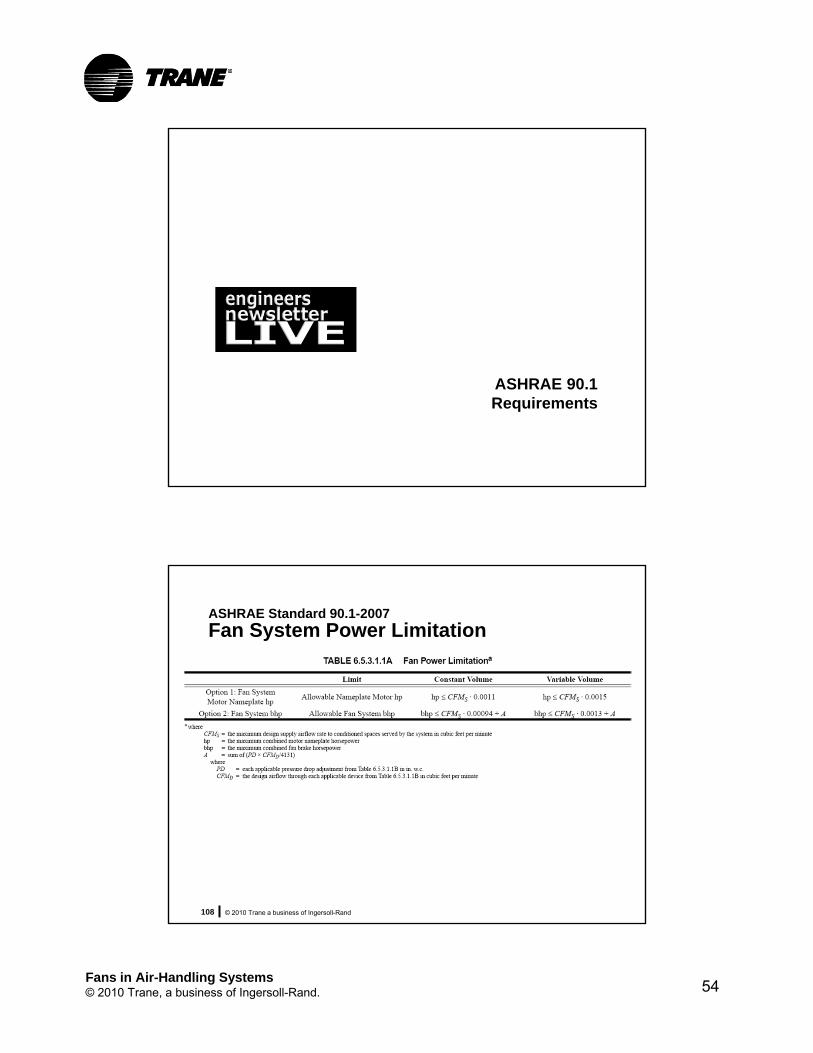
ASHRAE Standard 90.1-2007
Fan System Power Limitation

Fans in Air-Handling Systems© 2010 Trane, a business of Ingersoll-Rand. 55
© 2010 Trane a business of Ingersoll-Rand109
ASHRAE 90.1-2007: Fan System Power Limitation
Option 1: Motor Nameplate Horsepower
example: 30,000 cfm VAV system
allowable nameplate motor hp ≤ 45 (30,000 0.0015)
© 2010 Trane a business of Ingersoll-Rand110
ASHRAE 90.1-2007: Fan System Power Limitation
Option 2: Fan System Brake Horsepower
example: 30,000 cfm VAV system
allowable fan system bhp ≤ 39 (30,000 0.0013)
Fans in Air-Handling Systems© 2010 Trane, a business of Ingersoll-Rand. 56
© 2010 Trane a business of Ingersoll-Rand111
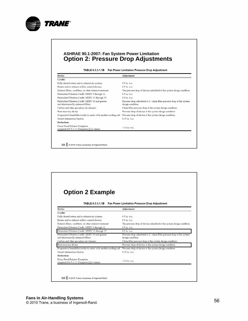
ASHRAE 90.1-2007: Fan System Power Limitation
Option 2: Pressure Drop Adjustments
© 2010 Trane a business of Ingersoll-Rand112
Option 2 Example
Fans in Air-Handling Systems© 2010 Trane, a business of Ingersoll-Rand. 57
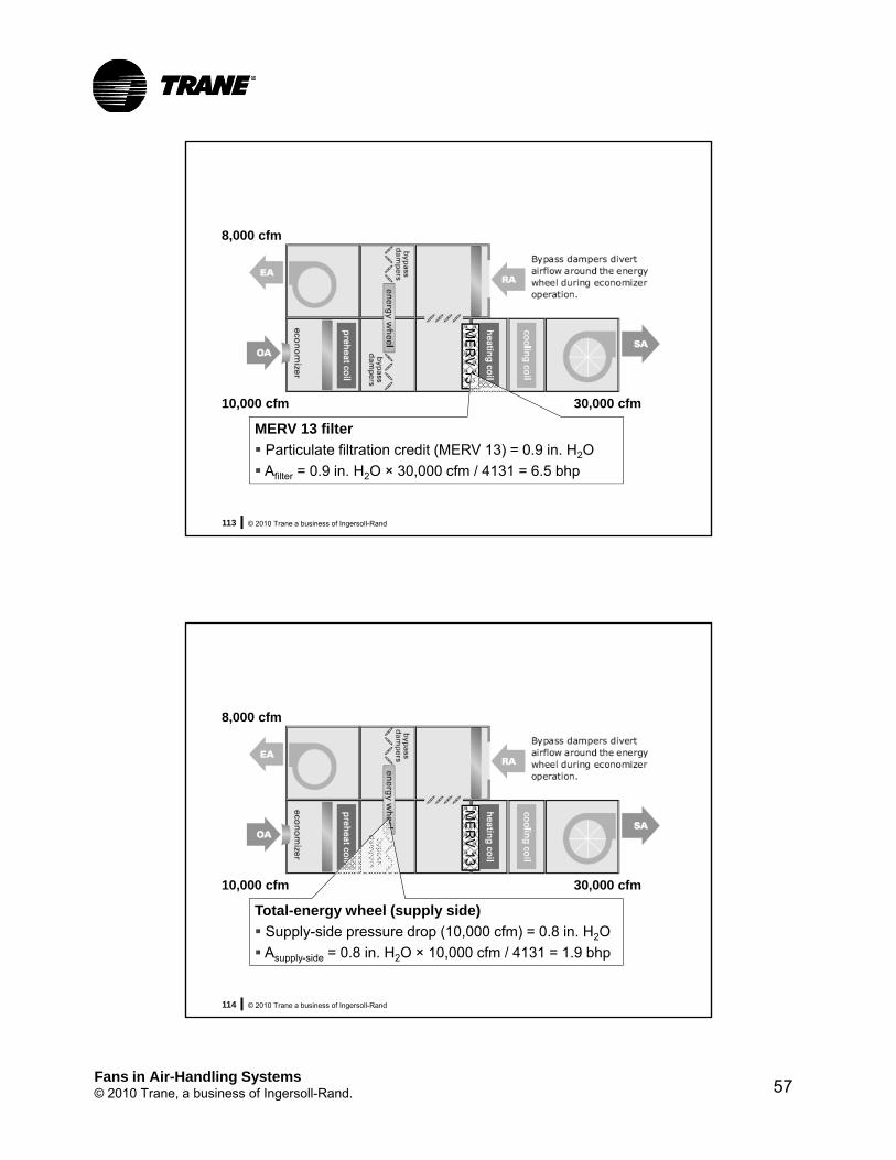
© 2010 Trane a business of Ingersoll-Rand113
ME
RV
13
30,000 cfm10,000 cfm
8,000 cfm
MERV 13 filter
Particulate filtration credit (MERV 13) = 0.9 in. H2O
Afilter = 0.9 in. H2O × 30,000 cfm / 4131 = 6.5 bhp
© 2010 Trane a business of Ingersoll-Rand114
ME
RV
13
30,000 cfm10,000 cfm
8,000 cfm
Total-energy wheel (supply side)
Supply-side pressure drop (10,000 cfm) = 0.8 in. H2O
Asupply-side = 0.8 in. H2O × 10,000 cfm / 4131 = 1.9 bhp

Fans in Air-Handling Systems© 2010 Trane, a business of Ingersoll-Rand. 58
© 2010 Trane a business of Ingersoll-Rand115
ME
RV
13
30,000 cfm10,000 cfm
8,000 cfm
Total-energy wheel (exhaust side)
Supply-side pressure drop (8,000 cfm) = 0.7 in. H2O
Aexhaust-side = 0.7 in. H2O × 8,000 cfm / 4131 = 1.4 bhp
© 2010 Trane a business of Ingersoll-Rand116
Option 2 Example
MERV 13 filter Afilter = 0.9 in. H2O × 30,000 cfm / 4131 = 6.5 bhp
Total-energy wheel Asupply-side = 0.8 in. H2O × 10,000 cfm / 4131 = 1.9 bhp
Aexhaust-side = 0.7 in. H2O × 8,000 cfm / 4131 = 1.4 bhp
A = 6.5 + 1.9 + 1.4 = 9.8 bhp
allowable fan system bhp ≤ 48.8 (30,000 0.0013 + 9.8)

Fans in Air-Handling Systems© 2010 Trane, a business of Ingersoll-Rand. 59
© 2010 Trane a business of Ingersoll-Rand117
Ways to Reduce Fan Power
1. Reduce airflow• Reduce cooling loads (better envelope, fewer and
better windows, more efficient lighting)
• Colder supply-air temperature
2. Reduce airside pressure loss • Efficient duct fittings
• Larger ductwork
• Larger air-handling unit
• Low pressure drop filters and coils
3. Select a higher-efficiency fan (if you have the choice)
© 2010 Trane a business of Ingersoll-Rand118
30B Draw-thru; 22.375-inch FC; without inlet vanes
11
10
9
8
7
6
5
4
3
2
1
0
tota
l st
atic
pre
ssu
re (
in H
2O)
airflow (cfm)
0 5000 10000 15000 20000 25000 30000 35000 40000 45000
25 %WO
50 %WO
60 %WO
70 %WO
80 %WO
90 %WO
1273 RPM
1200 RPM
1100 RPM
1000 RPM
900 RPM
800 RPM
700 RPM
600 RPM
500 RPM
400 RPM
B 15.2 bhp
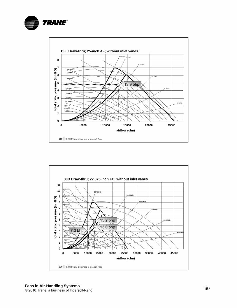
Fans in Air-Handling Systems© 2010 Trane, a business of Ingersoll-Rand. 60
© 2010 Trane a business of Ingersoll-Rand119
D30 Draw-thru; 25-inch AF; without inlet vanesto
tal
stat
ic p
ress
ure
(in
H2O
)
airflow (cfm)
1650 RPM
1600 RPM
1500 RPM
1400 RPM
1300 RPM
1200 RPM
1100 RPM
1000 RPM
900 RPM
800 RPM
700 RPM
45 %WO
60 %WO
50 %WO
70 %WO
80 %WO
90 %WO
8
7
6
5
4
3
2
1
0
0 5000 10000 15000 20000 25000
3 13.9 bhp
© 2010 Trane a business of Ingersoll-Rand120
30B Draw-thru; 22.375-inch FC; without inlet vanes
11
10
9
8
7
6
5
4
3
2
1
0
tota
l st
atic
pre
ssu
re (
in H
2O)
airflow (cfm)
0 5000 10000 15000 20000 25000 30000 35000 40000 45000
25 %WO
50 %WO
60 %WO
70 %WO
80 %WO
90 %WO
1273 RPM
1200 RPM
1100 RPM
1000 RPM
900 RPM
800 RPM
700 RPM
600 RPM
500 RPM
400 RPM
B
7.3 bhp 1
2 13.0 bhp
15.2 bhp
Fans in Air-Handling Systems© 2010 Trane, a business of Ingersoll-Rand. 61
© 2010 Trane a business of Ingersoll-Rand121
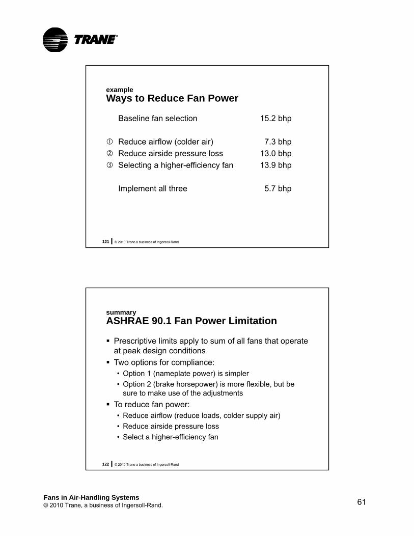
example
Ways to Reduce Fan Power
Baseline fan selection 15.2 bhp
Reduce airflow (colder air) 7.3 bhp
Reduce airside pressure loss 13.0 bhp
Selecting a higher-efficiency fan 13.9 bhp
Implement all three 5.7 bhp
© 2010 Trane a business of Ingersoll-Rand122
summary
ASHRAE 90.1 Fan Power Limitation
Prescriptive limits apply to sum of all fans that operate at peak design conditions
Two options for compliance:• Option 1 (nameplate power) is simpler
• Option 2 (brake horsepower) is more flexible, but be sure to make use of the adjustments
To reduce fan power:• Reduce airflow (reduce loads, colder supply air)
• Reduce airside pressure loss
• Select a higher-efficiency fan
Fans in Air-Handling Systems© 2010 Trane, a business of Ingersoll-Rand. 62
© 2010 Trane a business of Ingersoll-Rand123
summary
Fans in Air-Handling Systems
The right fan depends on the application, and is often based on balancing efficiency, acoustics, and cost.
It is important to understand how the fan will interact within the system.• Dirty filters and wet cooling coils
• Fan modulation in a VAV system
• System effect
Sound data taken in accordance with AHRI 260 provides the best indication of sound produced by the entire air-handling unit.
© 2010 Trane a business of Ingersoll-Rand124
References for This Broadcast
Where to Learn More
www.trane.com/EN

Fans in Air-Handling Systems© 2010 Trane, a business of Ingersoll-Rand. 63
© 2010 Trane a business of Ingersoll-Rand125
Watch Past Broadcasts
ENL Archives
www.trane.com/ENL
Insightful topics on HVAC system design:• Chilled-water plants• Air distribution• Refrigerant-to-air systems• Control strategies• Industry standards and LEED• Energy and the environment• Acoustics• Ventilation• Dehumidification
© 2010 Trane a business of Ingersoll-Rand126
2010 ENL Broadcasts
May Central Geothermal Systems
October ASHRAE Standard 90.1-2010
Top Related