


Languages
Pages
Legal


Multi-Bowl Applications
Components
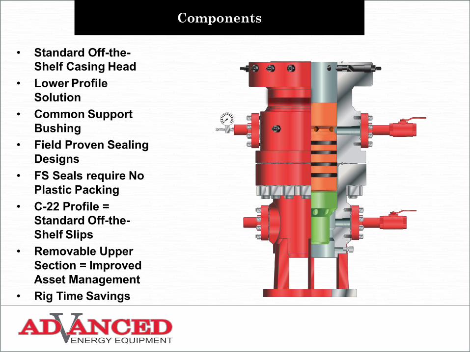
• Standard Off-the-Shelf Casing Head
• Lower Profile Solution
• Common Support Bushing
• Field Proven Sealing Designs
• FS Seals require No Plastic Packing
• C-22 Profile = Standard Off-the-Shelf Slips
• Removable Upper Section = Improved Asset Management
• Rig Time Savings
COMPONENTS
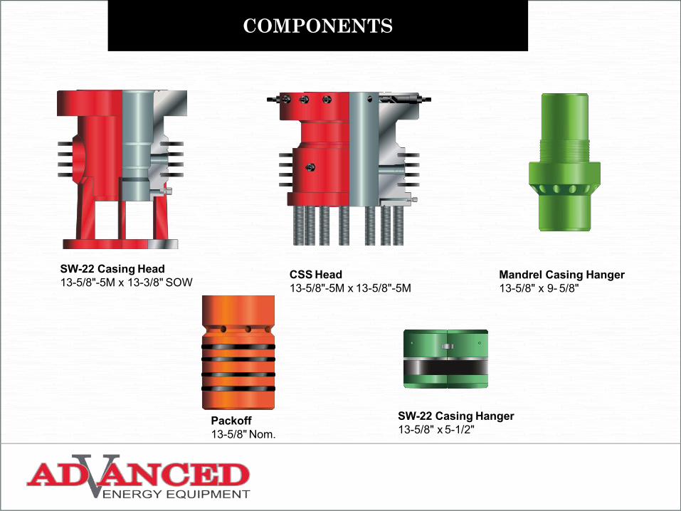
CSS Head13-5/8"-5M x 13-5/8"-5M
SW-22 Casing Head13-5/8"-5M x 13-3/8" SOW
SW-22 Casing Hanger13-5/8" x 5-1/2"
Packoff13-5/8" Nom.
Mandrel Casing Hanger13-5/8" x 9- 5/8"
INSTALLATION
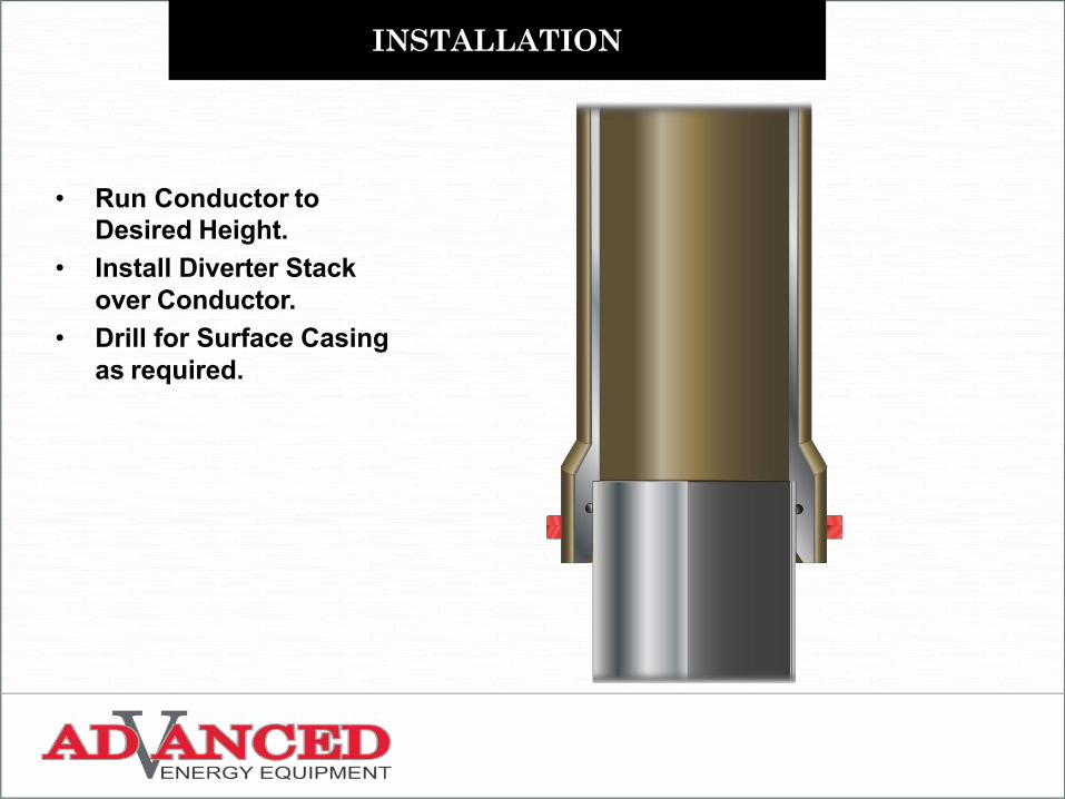
• Run Conductor toDesired Height.
• Install Diverter Stack over Conductor.
• Drill for Surface Casingas required.
INSTALLATION
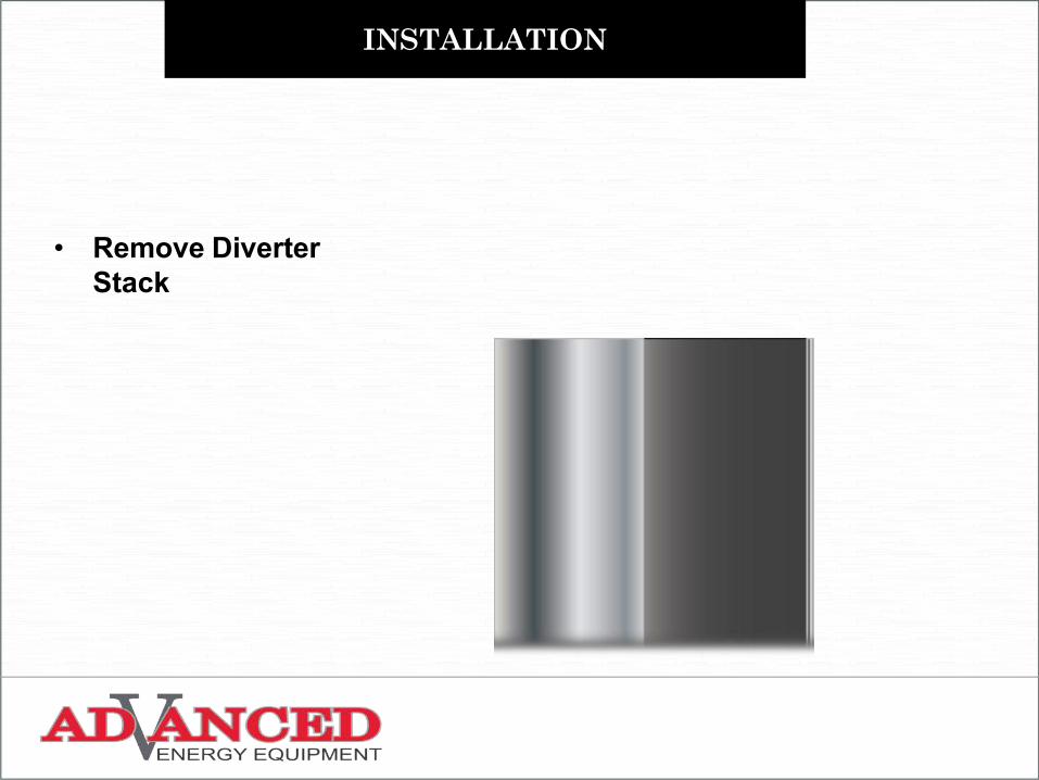
• Remove Diverter Stack
INSTALLATION
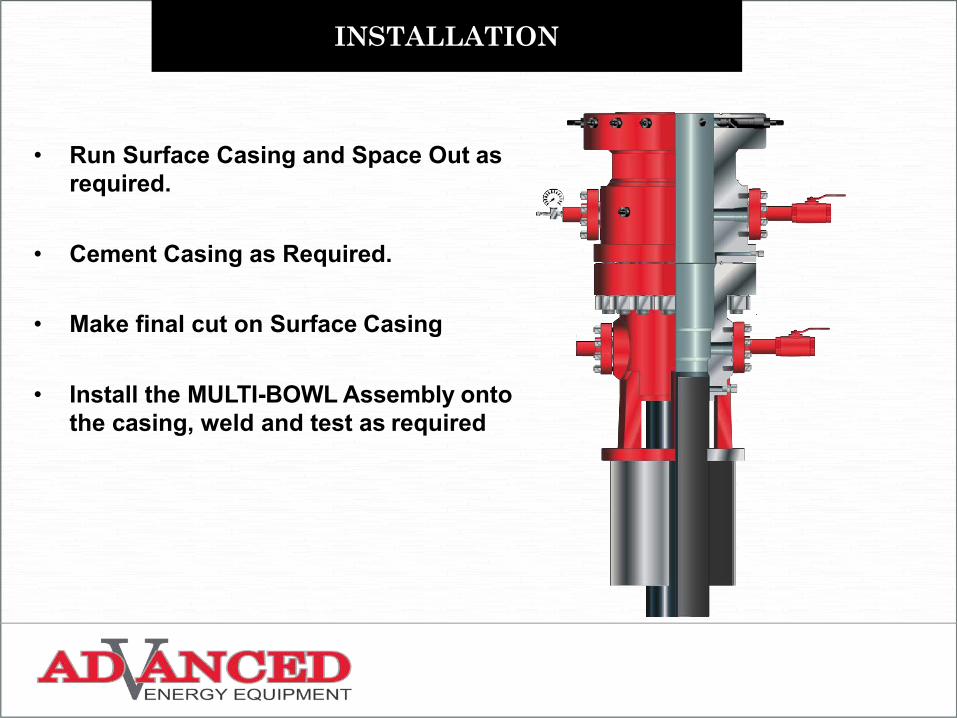
• Run Surface Casing and Space Out as required.
• Cement Casing as Required.
• Make final cut on Surface Casing
• Install the MULTI-BOWL Assembly onto the casing, weld and test as required
INSTALLATION
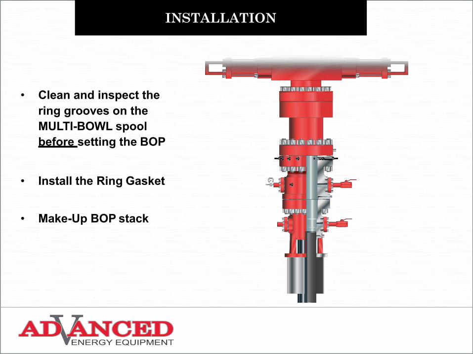
• Clean and inspect the ring grooves on the MULTI-BOWL spool before setting the BOP
• Install the Ring Gasket
• Make-Up BOP stack
INSTALLATION
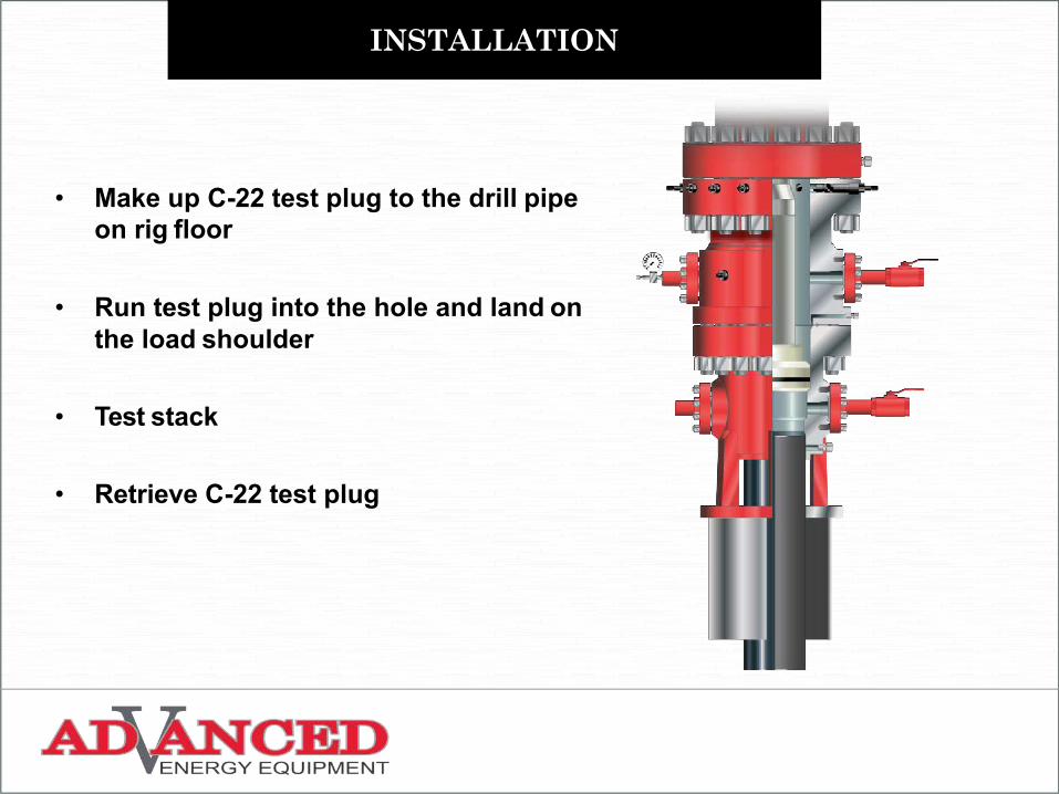
• Make up C-22 test plug to the drill pipe on rig floor
• Run test plug into the hole and land on the load shoulder
• Test stack
• Retrieve C-22 test plug

INSTALLATION
• Make up Long Wear Bushing Running Tool to the drill pipe on rig floor
• Insert running tool onto Wear Bushing through the J slots, rotate to the right until the stop
• Run the Wear Bushing into the well bore and land on the load shoulder.
INSTALLATION
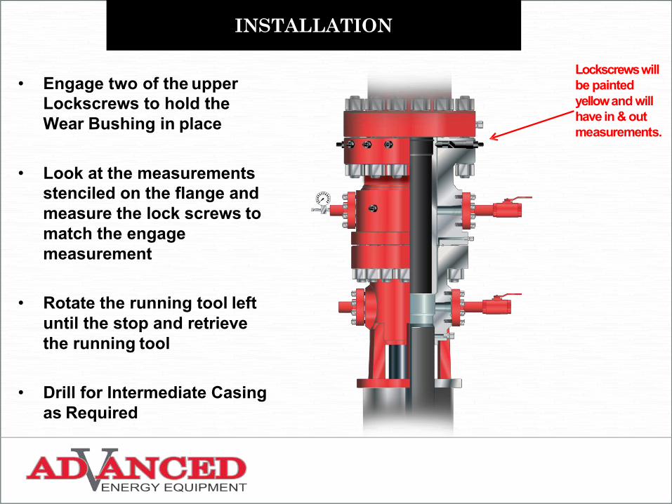
• Engage two of the upper Lockscrews to hold the Wear Bushing in place
• Look at the measurements stenciled on the flange and measure the lock screws to match the engage measurement
• Rotate the running tool left until the stop and retrieve the running tool
• Drill for Intermediate Casing as Required
Lockscrews will be painted yellow and will have in & out measurements.
INSTALLATION
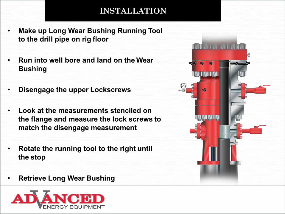
• Make up Long Wear Bushing Running Tool to the drill pipe on rig floor
• Run into well bore and land on the Wear Bushing
• Disengage the upper Lockscrews
• Look at the measurements stenciled on the flange and measure the lock screws to match the disengage measurement
• Rotate the running tool to the right until the stop
• Retrieve Long Wear Bushing
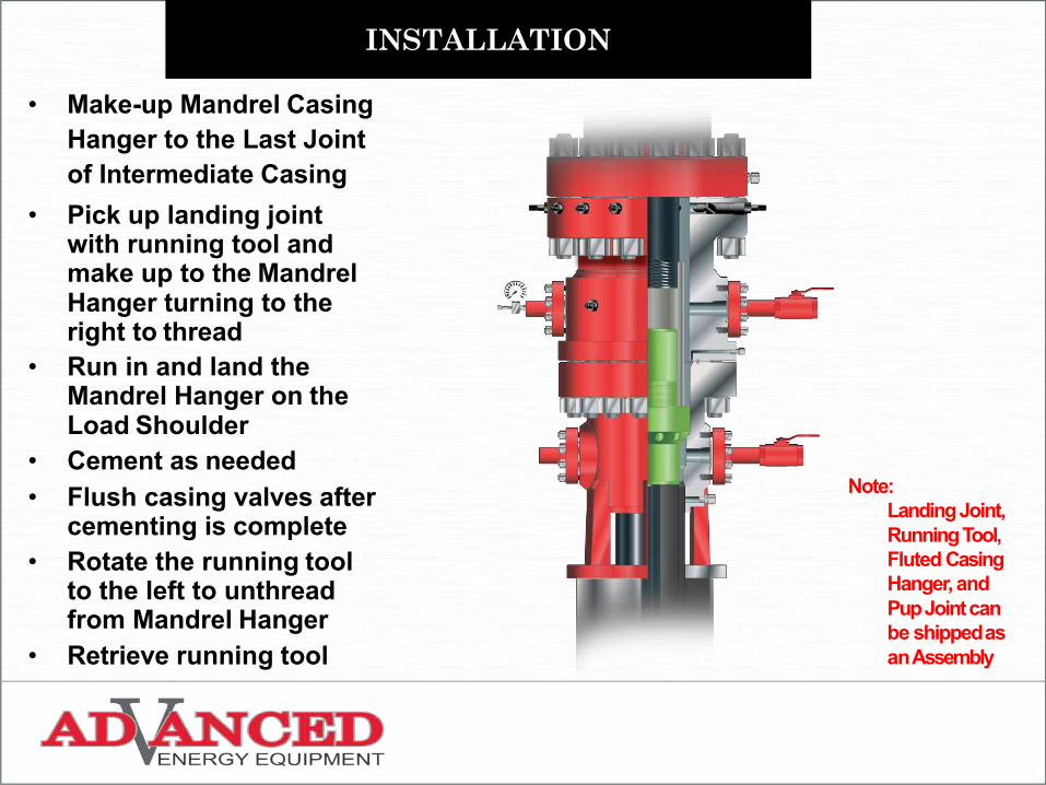
• Make-up Mandrel Casing Hanger to the Last Joint of Intermediate Casing
• Pick up landing joint with running tool and make up to the Mandrel Hanger turning to the right to thread
• Run in and land the Mandrel Hanger on the Load Shoulder
• Cement as needed• Flush casing valves after
cementing is complete• Rotate the running tool
to the left to unthread from Mandrel Hanger
• Retrieve running tool
INSTALLATION
Note:Landing Joint, Running Tool, Fluted Casing Hanger, and Pup Joint can be shippedas anAssembly

INSTALLATION
• Make-up Packoff Running Tool to the drill pipe on the rig floor
• Insert running tool onto Packoff through the J slots, rotate to the right until the stop
INSTALLATION
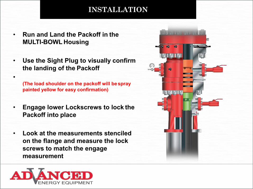
• Run and Land the Packoff in the MULTI-BOWL Housing
• Use the Sight Plug to visually confirm the landing of the Packoff
•(The load shoulder on the packoff will bespraypainted yellow for easy confirmation)
• Engage lower Lockscrews to lock the Packoff into place
• Look at the measurements stenciled on the flange and measure the lock screws to match the engage measurement
INSTALLATION
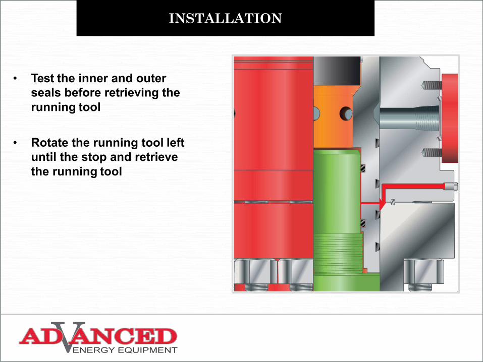
• Test the inner and outer seals before retrieving the running tool
• Rotate the running tool left until the stop and retrieve the running tool

INSTALLATION
• Make up C-22 test plug to the drill pipe on rig floor
• Run test plug into the hole and land on the load shoulder
• Test stack
• Retrieve C-22 test plug
INSTALLATION
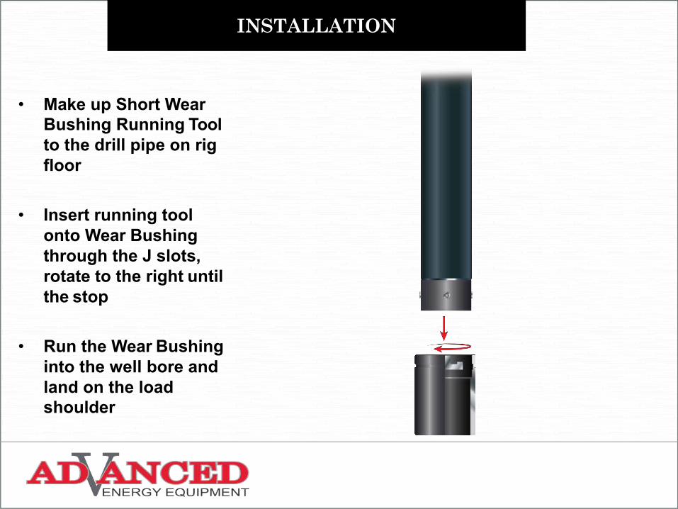
• Make up Short Wear Bushing Running Tool to the drill pipe on rig floor
• Insert running tool onto Wear Bushing through the J slots, rotate to the right until the stop
• Run the Wear Bushing into the well bore and land on the load shoulder
INSTALLATION
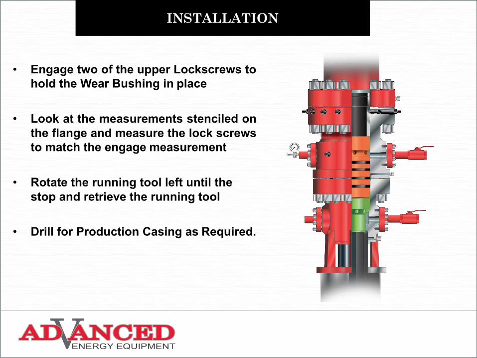
• Engage two of the upper Lockscrews tohold the Wear Bushing in place
• Look at the measurements stenciled onthe flange and measure the lock screwsto match the engage measurement
• Rotate the running tool left until the stop and retrieve the running tool
• Drill for Production Casing as Required.
INSTALLATION
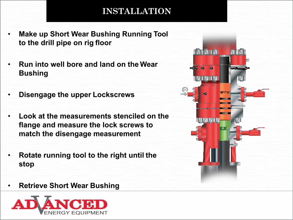
• Make up Short Wear Bushing Running Tool to the drill pipe on rig floor
• Run into well bore and land on the Wear Bushing
• Disengage the upper Lockscrews
• Look at the measurements stenciled on the flange and measure the lock screws to match the disengage measurement
• Rotate running tool to the right until the stop
• Retrieve Short Wear Bushing
INSTALLATION
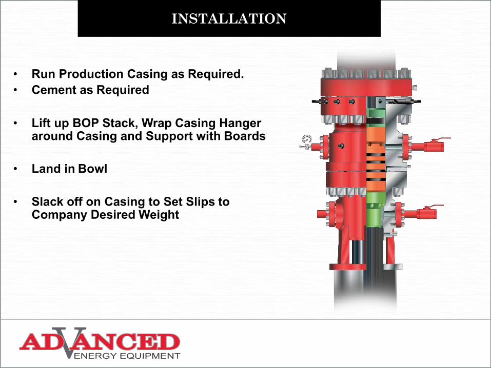
• Run Production Casing as Required.• Cement as Required
• Lift up BOP Stack, Wrap Casing Hanger around Casing and Support with Boards
• Land in Bowl
• Slack off on Casing to Set Slips to Company Desired Weight
INSTALLATION
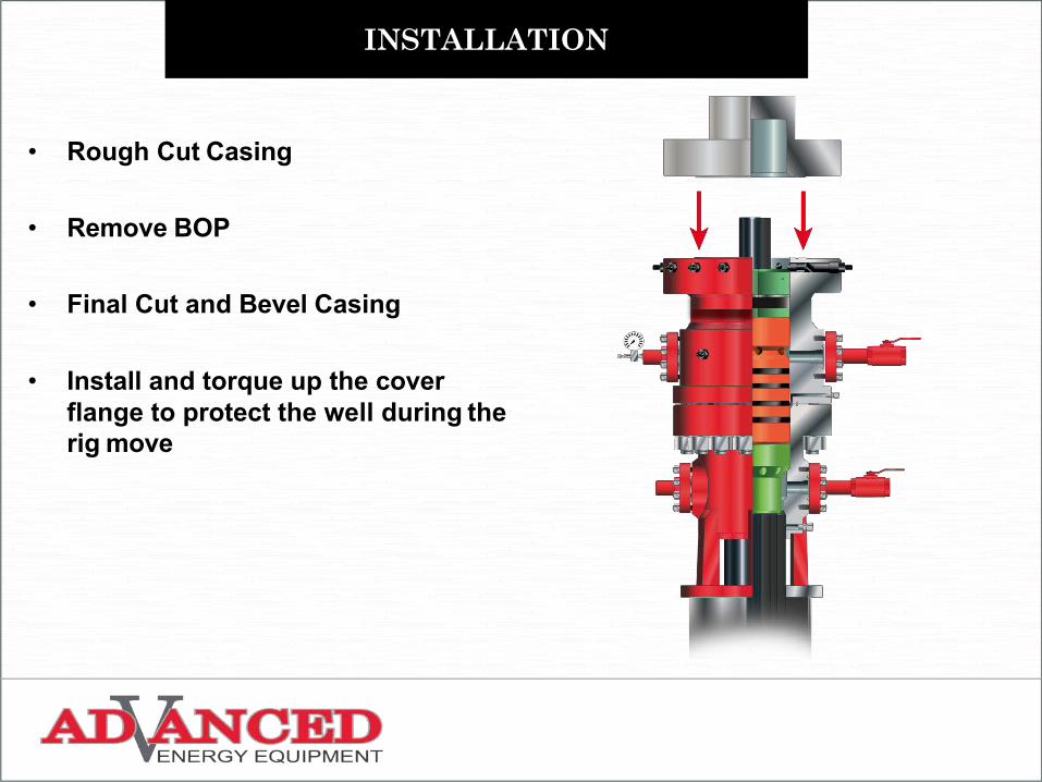
• Rough Cut Casing
• Remove BOP
• Final Cut and Bevel Casing
• Install and torque up the cover flange to protect the well during the rig move
INSTALLATION
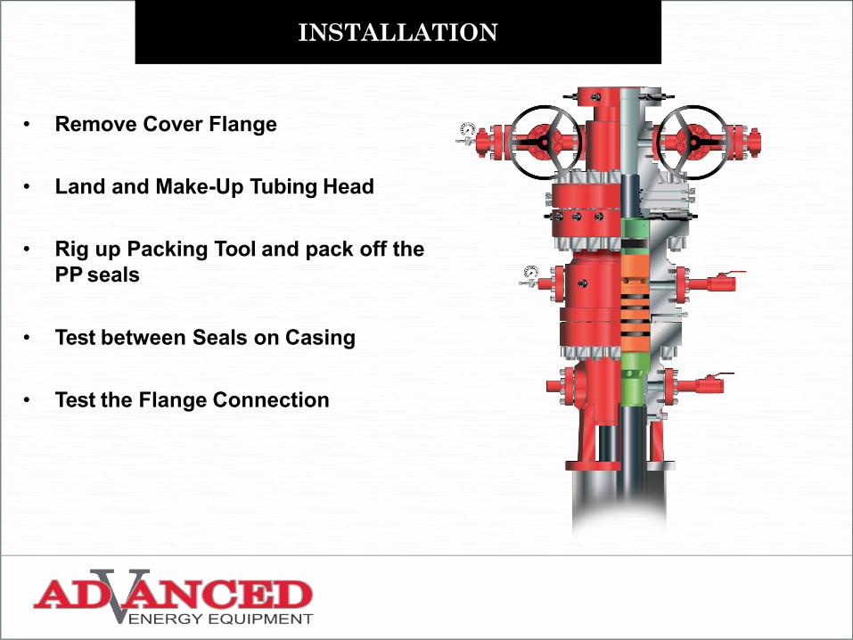
• Remove Cover Flange
• Land and Make-Up Tubing Head
• Rig up Packing Tool and pack off the PP seals
• Test between Seals on Casing
• Test the Flange Connection

INSTALLATION
• Make-up the Frac Tree Assembly.• Frac Down Production Casing as Required.
INSTALLATION
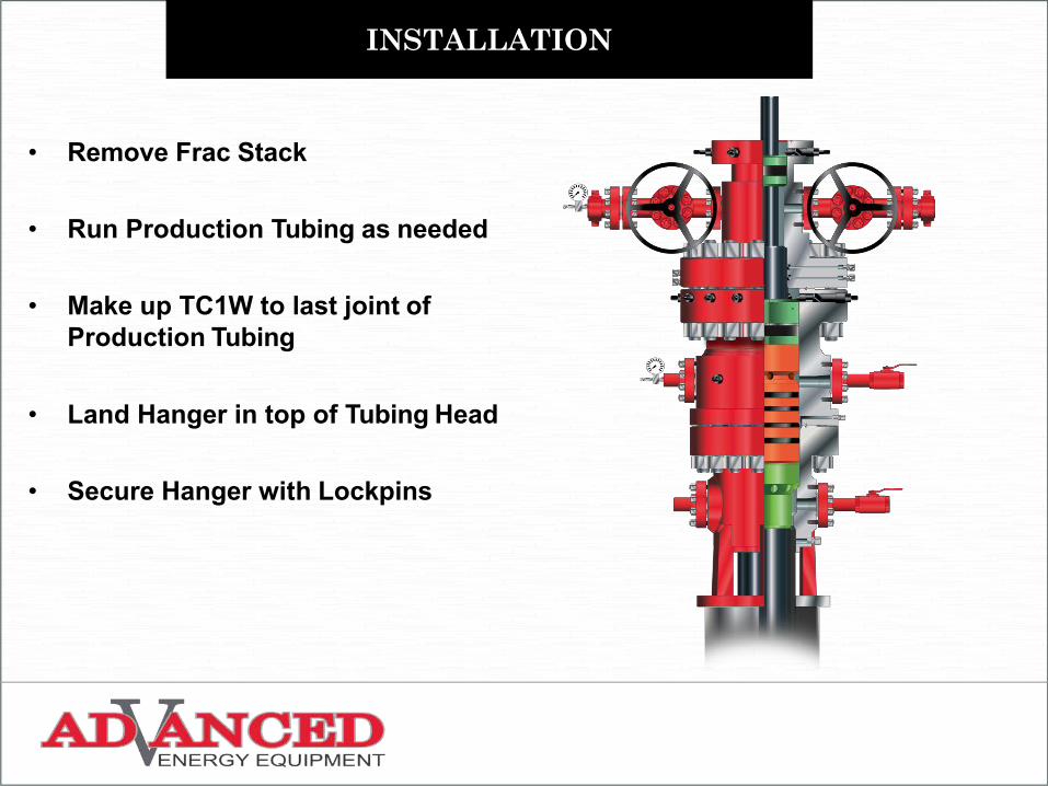
• Remove Frac Stack
• Run Production Tubing as needed
• Make up TC1W to last joint of Production Tubing
• Land Hanger in top of Tubing Head
• Secure Hanger with Lockpins
INSTALLATION
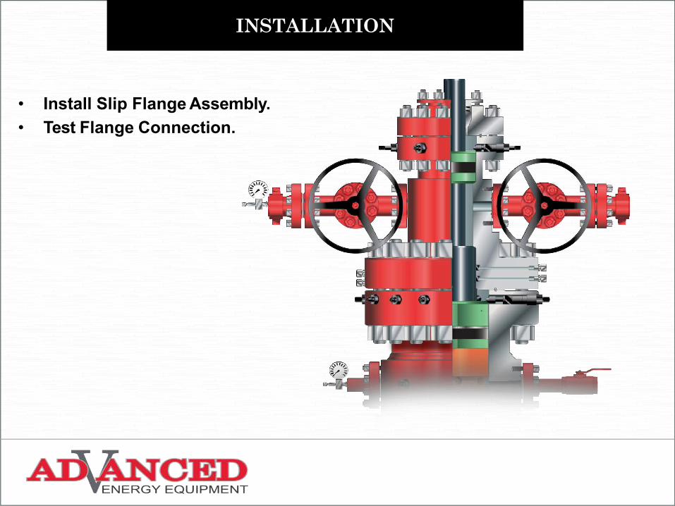
• Install Slip Flange Assembly.• Test Flange Connection.
Top Related