


Languages
Pages
Legal

ELECTRICAL
5-� © 2006
800/458-0289 www.organsupply.com
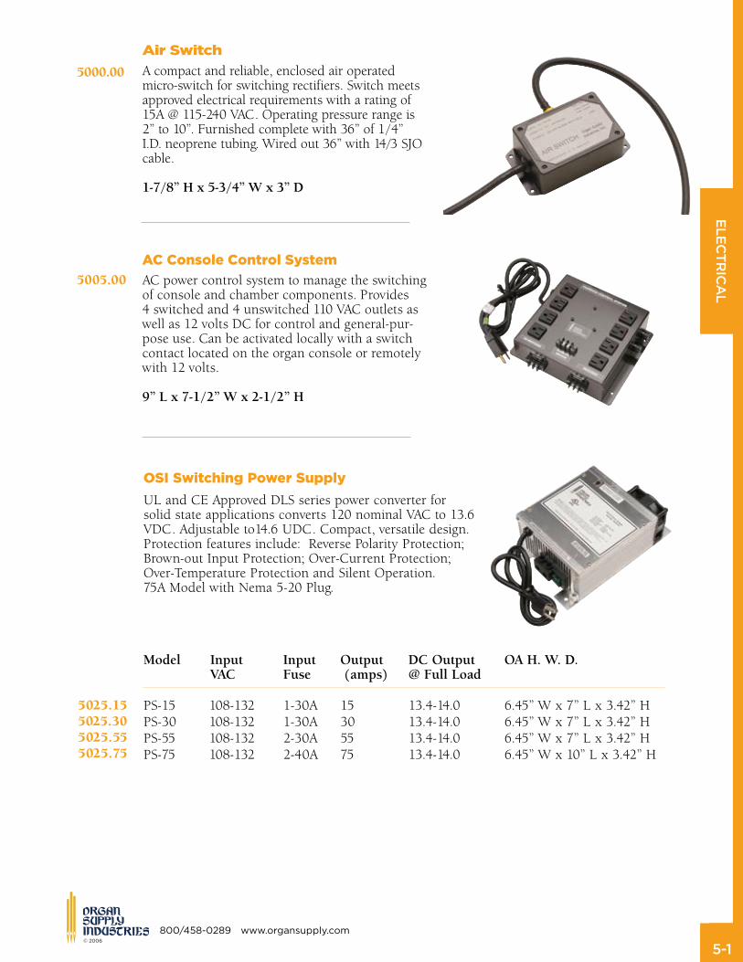
OSI Switching Power Supply
UL and CE Approved DLS series power converter for solid state applications converts 120 nominal VAC to 13.6 VDC. Adjustable to14.6 UDC. Compact, versatile design. Protection features include: Reverse Polarity Protection; Brown-out Input Protection; Over-Current Protection; Over-Temperature Protection and Silent Operation. 75A Model with Nema 5-20 Plug.
Model Input Input Output DCOutput OAH.W.D. VAC Fuse (amps) @FullLoad
PS-15 108-132 1-30A 15 13.4-14.0 6.45” W x 7” L x 3.42” HPS-30 108-132 1-30A 30 13.4-14.0 6.45” W x 7” L x 3.42” HPS-55 108-132 2-30A 55 13.4-14.0 6.45” W x 7” L x 3.42” HPS-75 108-132 2-40A 75 13.4-14.0 6.45” W x 10” L x 3.42” H
Air Switch
A compact and reliable, enclosed air operated micro-switch for switching rectifiers. Switch meets approved electrical requirements with a rating of 15A @ 115-240 VAC. Operating pressure range is 2” to 10”. Furnished complete with 36” of 1/4” I.D. neoprene tubing. Wired out 36” with 14/3 SJO cable.
1-7/8”Hx5-3/4”Wx3”D
AC Console Control System
AC power control system to manage the switching of console and chamber components. Provides 4 switched and 4 unswitched 110 VAC outlets as well as 12 volts DC for control and general-pur-pose use. Can be activated locally with a switch contact located on the organ console or remotely with 12 volts.
9”Lx7-1/2”Wx2-1/2”H
5000.00
5005.00
5025.155025.305025.555025.75
ELECTRICAL
5-� © 2006
www.organsupply.com 800/458-0289
Size UseFunctionAmperes Volts
GMC 5 Astron Rectifier Input 5 250 VACGMC 8 Astron Rectifier Input 8 250 VACGMC 10 Astron Rectifier Input 10 250 VACABC 6 Astron Rectifier Input 6 250 VAC
MTH 5 F-R Rectifier Input 5 240 VACGLH 10 F-R Rectifier Input 10 120 VACBAF 30 F-R Rectifier Output 30 10-15 VDC
ATC 30 OSI Power Supply Output 30 32 VDCATC 40 OSI Power Supply Output 40 32 VDC
AGC 0.1 E-M Chime Relay 0.1 125 VACAGC 6 Organ Circuits 6 250 VAC Chime Rail
MDQ 1 General Time Delay 250 VACAGC 3 General Input 3 250 VAC
5050.12
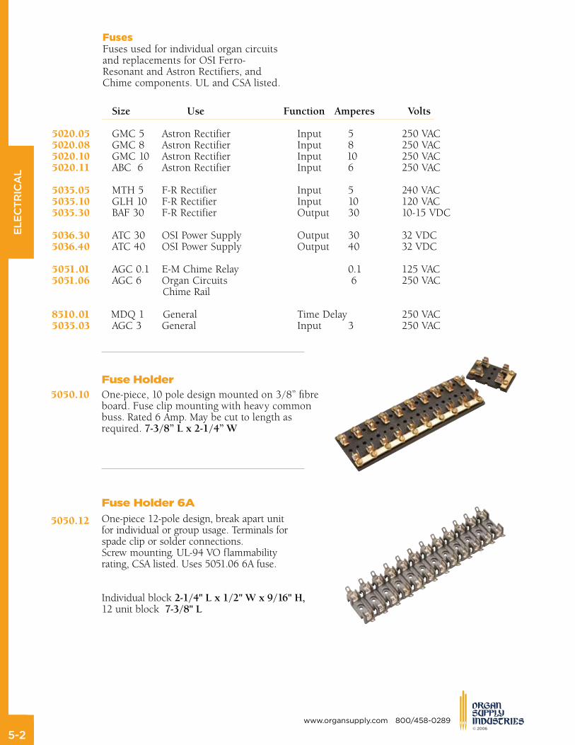
Fuse Holder 6A
One-piece 12-pole design, break apart unit for individual or group usage. Terminals for spade clip or solder connections. Screw mounting. UL-94 VO flammability rating, CSA listed. Uses 5051.06 6A fuse.
Individual block 2-1/4"Lx1/2"Wx9/16"H,12 unit block7-3/8"L
5050.10Fuse Holder One-piece, 10 pole design mounted on 3/8” fibre board. Fuse clip mounting with heavy common buss. Rated 6 Amp. May be cut to length as required. 7-3/8”Lx2-1/4”W
5020.055020.085020.105020.11
5035.055035.105035.30
5036.305036.40
5051.015051.06
8510.015035.03
FusesFuses used for individual organ circuitsand replacements for OSI Ferro-Resonant and Astron Rectifiers, andChime components. UL and CSA listed.
ELECTRICAL
5-� © 2006
800/458-0289 www.organsupply.com
B&S Gauge Color Construction
5122.00 22 White Solid
5124.00 24 White Solid
5126.00 26 White Solid5126.01 26 Blue Solid5126.02 26 Green Solid5126.03 26 Red Solid 26 Yellow Solid 26 Black Solid
5127.00 26 White Stranded5127.01 26 Blue Stranded5127.02 26 Green Stranded5127.03 26 Red Stranded5127.04 26 Yellow Stranded 26 Black Stranded
5128.00 28 White Solid5128.01 28 Blue Solid5128.02 28 Green Solid5128.03 28 Red Solid5128.04 28 Yellow Solid
5122.00
5124.00
5126.005126.015126.025126.035126.045126.05
5127.005127.015127.025127.035127.045127.05
5128.005128.015128.025128.035128.04
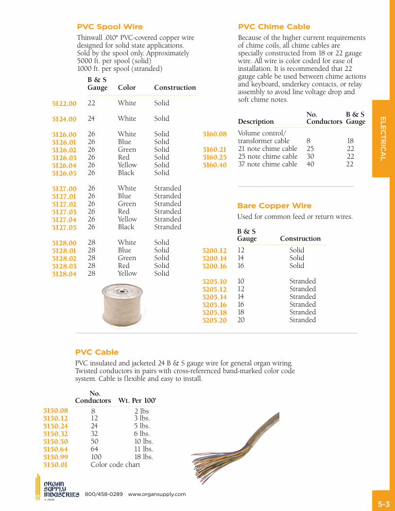
PVC Spool Wire
Thinwall .010" PVC-covered copper wire designed for solid state applications. Sold by the spool only. Approximately 5000 ft. per spool (solid) 1000 ft. per spool (stranded)
PVC Cable
PVC insulated and jacketed 24 B & S gauge wire for general organ wiring.Twisted conductors in pairs with cross-referenced band-marked color codesystem. Cable is flexible and easy to install.
No.Conductors Wt.Per100'
5150.085150.125150.245150.325150.505150.645150.995150.01
PVC Chime Cable
Because of the higher current requirementsof chime coils, all chime cables are specially constructed from 18 or 22 gauge wire. All wire is color coded for ease of installation. It is recommended that 22 gauge cable be used between chime actions and keyboard, underkey contacts, or relay assembly to avoid line voltage drop and soft chime notes. No. B&SDescription ConductorsGauge
Volume control/transformer cable 8 18 21 note chime cable 25 22 25 note chime cable 30 2237 note chime cable 40 22
5160.08
5160.215160.255160.40
Bare Copper Wire
Used for common feed or return wires.
B&SGauge Construction
12 Solid 14 Solid 16 Solid
10 Stranded 12 Stranded 14 Stranded 16 Stranded 18 Stranded 20 Stranded
5200.125200.145200.16
5205.105205.125205.145205.165205.185205.20
12 3 lbs. 24 5 lbs. 32 6 lbs. 50 10 lbs. 64 11 lbs. 100 18 lbs.Color code chart
8 2 lbs
Size UseFunctionAmperes Volts
GMC 5 Astron Rectifier Input 5 250 VACGMC 8 Astron Rectifier Input 8 250 VACGMC 10 Astron Rectifier Input 10 250 VACABC 6 Astron Rectifier Input 6 250 VAC
MTH 5 F-R Rectifier Input 5 240 VACGLH 10 F-R Rectifier Input 10 120 VACBAF 30 F-R Rectifier Output 30 10-15 VDC
ATC 30 OSI Power Supply Output 30 32 VDCATC 40 OSI Power Supply Output 40 32 VDC
AGC 0.1 E-M Chime Relay 0.1 125 VACAGC 6 Organ Circuits 6 250 VAC Chime Rail
MDQ 1 General Time Delay 250 VACAGC 3 General Input 3 250 VAC
ELECTRICAL
5-� © 2006
www.organsupply.com 800/458-0289
Copper Grounding Strip
Easily installed soft copper grounding strip provides one wire installation of 601 magnets. The pressure sensitive adhesive is backed with release paper. It is readily soldered for permanent electrical joints and is easily pierced to accept screws and solder lugs.
Size
.009"x5/8"x100'
Insulated Copper Wire
Used for DC main wiring. B&SGauge Construction Color
6 Stranded Black 6 Stranded White 8 Stranded Black 8 Stranded White 10 Solid Black10 Solid White12 Solid Black 12 Solid White 14 Solid Black 14 Solid White
5210.065210.075210.085210.095210.105210.115210.125210.135210.145210.15
Insulated Hookup Wire
PVC covered in 100 ft. spools.
B&SGauge Color
18 Black 20 White
5220.185220.20
Braided Copper Wire
Flexible, flat braided copper wire, useful for flexible mains.
Size
1/16" 1/8" 3/16" 1/4" 5/8"
5230.015230.025230.035230.045230.05
Phosphor Bronze Wire
36" straight lengths except * which are coiled stock. B&SGauge Inches mm
8 .1284 3.2636 9 .1144 2.9065 10 .1018 2.5880 11 .0907 2.3048 12 .0808 2.0525 13 .0719 1.8278 14 .0640 1.6277 15 .0570 1.4495 18 .0403 1.0236 20 .0319 .8118 21 * .0284 .7229 22 * .0253 .6438 24 * .0201 .5105 26 * .0159 .4048 27 .0141 .3605 28 * .0126 .3210
5300.085300.095300.105300.115300.125300.135300.145300.155300.185300.205300.215300.225300.245300.265300.275300.28
Phosphor Bronze Strip
Size
.010 x 1/8"
.010 x 3/16"
.010 x 1/4"
.027 x 1/8"
.027 x 1/8" nickel plated
5310.015310.025310.035310.045310.05
5330.04

ELECTRICAL
5-5 © 2006
800/458-0289 www.organsupply.com
Silver Wire
36" straight lengths, 90% coin silver.
B&SGauge Inches mm UsedFor
21 .0285 .723 Buss Bars
22 .0253 .643 Expression Rollers
24 .0201 .511 Pedal Contacts 26 .0159 .404 27 .0142 .361 Manual Contacts
5400.21
5400.22
5400.24
5400.265400.27
Silver Strip
.010" x .123" in coil, 90% coin silver.5410.00
Channel Silver
“U” shaped channel for contact plates, 90% coin silver.
5420.00
ELECTRICAL
5-� © 2006
www.organsupply.com 800/458-0289
AdjuStABlePort
Description Ohms Port
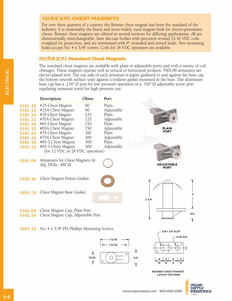
#25 Chest Magnet 90 Plain #25A Chest Magnet 90 Adjustable #70 Chest Magnet 125 Plain #70A Chest Magnet 125 Adjustable #65 Chest Magnet 150 Plain #65A Chest Magnet 150 Adjustable #75 Chest Magnet 180 Plain #75A Chest Magnet 180 Adjustable #65-3 Chest Magnet 300 Plain #65-3 Chest Magnet 300 Adjustable (for 12 VDC or 24 VDC operation)
Armatures for Chest Magnets & Adj. DVAs. .437Ø
Chest Magnet Donut Gasket.
Chest Magnet Base Gasket.
Chest Magnet Cap, Plain Port. Chest Magnet Cap, Adjustable Port.
No. 4 x 5/8" PH Phillips Mounting Screws.
5501.105501.125501.205501.225501.305501.325501.405501.425501.505501.53
5501.08
5502.56
5501.70
5502.095502.10
7604.54
CHeSt MAGnetSFor over three quarters of a century the Reisner chest magnet has been the standard of the industry. It is undeniably the finest and most widely used magnet built for electro-pneumatic chests. Reisner chest magnets are offered in several versions for differing applications. All are dimensionally interchangeable, have die-cast bodies with precision wound 12-16 VDC coils wrapped for protection, and are terminated with 6" stranded and tinned leads. Two mounting holes accept No. 4 x 5/8" screws. Coils for 24 VDC operation are available.
PlAinPort
The standard chest magnets are available with plain or adjustable ports and with a variety of coil ohmages. These magnets operate well in vertical or horizontal position. 5501.08 armatures are electro-plated iron. The top side of each armature is paper gasketed to seal against the base cap, the bottom smooth surface seals against a resilient gasket mounted in the base. The aluminum base cap has a .234" Ø port for low pressure operation or a .150" Ø adjustable screw port regulating armature travel for high pressure use.
Standard Chest Magnets

ELECTRICAL
5-� © 2006
800/458-0289 www.organsupply.com
top note Magnet
The standard Reisner chest magnet with a counter-bored base screw is used to play small treble pipes. The foot of the pipe seats directly on the countersunk magnet cap. The 5501.09 armature, which acts as a valve, is held in place by a small coil spring. 60 ohm coil.
PipeHole
1/8" 3/16"
Player Piano Magnet
Designed to interface with piano and other vacuum actions. 1/8” brass nipple accommodates standard piano tubing and extends 1/2” from magnet cap. 60 ohm coil.
5909.105909.12
5909.14
reiSner C-17 Chest Magnets
The C-17 chest magnet features a flat base, special .563” diameter large armature paper gasketed on both sides, larger ports and latch-type cap. This magnet provides larger exhaust rate and is easily opened for cleaning. Operates best in vertical orientation.
5501.70
7604.54
Description Ohms Port
C-17A Chest Magnet 90 .234 C-17C Chest Magnet 90 .305C-17B Chest Magnet 150 .234C-17D Chest Magnet 150 .305
Armatures for C-17 Chest Magnets & Standard DVAs. .542Ø
C17 Chest Magnet Base Gasket.
No. 4 x 5/8" PH Phillips Mounting Screws.
Performance Data Chart on page 5-18
Performance Data Chart on pages 5-18 & 5-19
5511.105511.125511.205511.22
5501.09

ELECTRICAL
5-� © 2006
www.organsupply.com 800/458-0289
5521.085521.105521.125521.145521.165521.185521.20
5524.085524.105524.125524.145524.165524.185522.085522.105522.125522.145522.165522.18
5523.065523.085523.105523.125523.145523.165523.18
5525.085525.10
5521.95
5330.04
7604.54
The Reisner 601 Direct Pallet Magnet is the original unit against which all other available electro-mechanical magnets are measured. With recent refinements, it is a state-of-the-art magnet. The factory-adjusted soft felt and leather valves are cemented to an aluminum valve carrier. The valve assembly is firmly attached to the armature, eliminating loose or wandering valves. Patented two-piece design of the armature hinge will not rust or bind, assuring fast and positive operation under all conditions. Adjustable spring return is centered over the armature, providing an in-line, direct pull. Electro-plated steel construction provides long life protection in a variety of climates. Two-screw mounting provides worry free installation. The precision wound coils are covered with high temperature tape and terminate in tinned solder lugs, one of which is grounded to the frame for easy connection to a common buss. Voltage range is 10-15 VDC. Coils for higher voltages and other ohmages are available. Mounts with No. 4 x 5/8" screws. Ohms ValveSize
40 5/8"40 3/4" 40 7/8" 40 1" 40 1-1/8" 40 1-1/4"40 1-1/2"
60 5/8" 60 3/4" 60 7/8" 60 1" 60 1-1/8" 60 1-1/4" 90 5/8" 90 3/4" 90 7/8" 90 1" 90 1-1/8" 90 1-1/4” 150 1/2"150 5/8"150 3/4"150 7/8”150 1” 150 1-1/8”150 1-1/4”
300 5/8” (24 VDC) 300 3/4” (24 VDC)
Install diodes on magnets.
Copper Buss Strip. .009"x5/8"x100'
No. 4 x 5/8" PH Phillips Mounting Screws.
601 Direct Pallet Magnet
Performance Data Chart on page 5-18
Performance Data Chart on pages 5-18 & 5-19
VALVESIZE
ELECTRICAL
5-� © 2006
800/458-0289 www.organsupply.com
L
A
V P
1 1/4
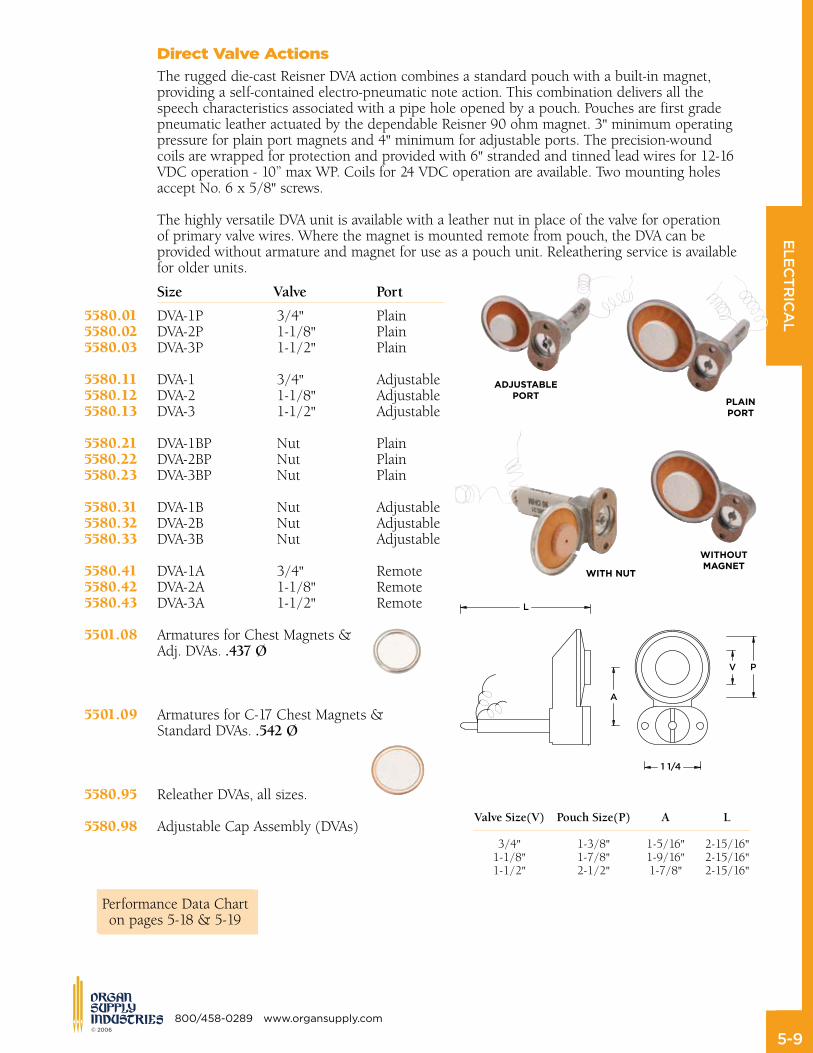
ValveSize(V) PouchSize(P) A L
3/4" 1-3/8" 1-5/16" 2-15/16" 1-1/8" 1-7/8" 1-9/16" 2-15/16" 1-1/2" 2-1/2" 1-7/8" 2-15/16"
Direct Valve Actions
The rugged die-cast Reisner DVA action combines a standard pouch with a built-in magnet, providing a self-contained electro-pneumatic note action. This combination delivers all the speech characteristics associated with a pipe hole opened by a pouch. Pouches are first grade pneumatic leather actuated by the dependable Reisner 90 ohm magnet. 3" minimum operating pressure for plain port magnets and 4" minimum for adjustable ports. The precision-wound coils are wrapped for protection and provided with 6" stranded and tinned lead wires for 12-16 VDC operation - 10” max WP. Coils for 24 VDC operation are available. Two mounting holes accept No. 6 x 5/8" screws. The highly versatile DVA unit is available with a leather nut in place of the valve for operation of primary valve wires. Where the magnet is mounted remote from pouch, the DVA can be provided without armature and magnet for use as a pouch unit. Releathering service is available for older units.
Size Valve Port
DVA-1P 3/4" Plain DVA-2P 1-1/8" Plain DVA-3P 1-1/2" Plain DVA-1 3/4" Adjustable DVA-2 1-1/8" Adjustable DVA-3 1-1/2" Adjustable DVA-1BP Nut Plain DVA-2BP Nut Plain DVA-3BP Nut Plain DVA-1B Nut Adjustable DVA-2B Nut Adjustable DVA-3B Nut Adjustable DVA-1A 3/4" Remote DVA-2A 1-1/8" Remote DVA-3A 1-1/2" Remote
Armatures for Chest Magnets &Adj. DVAs. .437Ø
Armatures for C-17 Chest Magnets & Standard DVAs. .542Ø
Releather DVAs, all sizes.
Adjustable Cap Assembly (DVAs)
AdjuStABlePort
WitH nut
WitHoutMAGnet
PlAinPort
5580.015580.025580.03
5580.115580.125580.13
5580.215580.225580.23
5580.315580.325580.33
5580.415580.425580.43
5501.08
5501.09
5580.95
5580.98
Performance Data Chart on page 5-18
Performance Data Chart on pages 5-18 & 5-19

ELECTRICAL
5-�0 © 2006
www.organsupply.com 800/458-0289
5581.015581.025581.03
Pedal Pouch Units
These individual pedal pouches extend the range of the time-proven Reisner Direct Valve Actions into the 16’ octave. The integrated DVA primary provides fast and quiet operation. They are designed for easy two screw installation over a single 5/8” Øexhaust hole. A paper mounting template is provided for each size. 90 ohm magnet
Size Valve O.A.LxWxH
PPA-1 2” 4-1/4” x 5-7/8” x 4-3/8”PPA-2 2-1/2” 5” x 6-5/8” x 4-3/8”PPA-3 3” 5-3/4” x 7-3/8” x 4-3/8”

ELECTRICAL
5-�� © 2006
800/458-0289 www.organsupply.com
Solid State Relay
OEM replacement for the Reisner C5 series. Designed to mount on the same centers as the C5 units. Output current 4 Amperes. Spark suppression diodes installed
Position Contacts Replacementfor
5531.02 Positive 15 5530.155531.04 Negative 15 5530.155531.06 Individual 8 5530.07
Impulse, Bi-Stable Relay
A convenient electro-mechanical reversible DPDT relay. Single 23 ohm coil energizes reversing mechanism changing position with each impulse. 12 VDC coil, contacts rated at 15 amperes. 1-1/2"Wx1-7/8"Hx3"L
5535.00
15 Count
8 Count
OSI Dual Magnetic Action Drawknob utilized single coil technology with optical isolation for stop control. Mounting options for either 3/4” or 1” jamb thickness available. Low combination system current load of 20mA @ 12 VDC eliminates the need for diodes or high current solid-state drivers. The solid-state switching device is capable of switching a 2 amp stop action load. Available with positive or negative coil common. Nominal coil load of 430mA @ 12.5 VDC. Unit includes header with plug (header may be direct terminate via ”wire-wrap”). Linear movement of .675”. May be supplied with drawknob engraved. Easily mounts with three #4 x 1/2” screws (not supplied).
Drawknob
JambVoltage
5725.01 3/4” 12V 5725.02 1” 12V5725.03 3/4” 24V5725.04 1” 24V
ELECTRICAL
5-�� © 2006
www.organsupply.com 800/458-0289
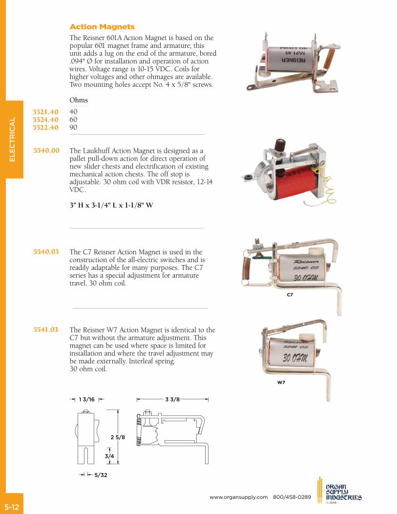
Action Magnets
The Reisner 601A Action Magnet is based on the popular 601 magnet frame and armature; this unit adds a lug on the end of the armature, bored .094" Ø for installation and operation of action wires. Voltage range is 10-15 VDC. Coils for higher voltages and other ohmages are available. Two mounting holes accept No. 4 x 5/8" screws.
Ohms
40 60 90
The Laukhuff Action Magnet is designed as a pallet pull-down action for direct operation of new slider chests and electrification of existing mechanical action chests. The off stop is adjustable. 30 ohm coil with VDR resistor, 12-14 VDC.
3"Hx3-1/4"Lx1-1/8"W
The C7 Reisner Action Magnet is used in the construction of the all-electric switches and is readily adaptable for many purposes. The C7 series has a special adjustment for armature travel. 30 ohm coil.
The Reisner W7 Action Magnet is identical to the C7 but without the armature adjustment. This magnet can be used where space is limited for installation and where the travel adjustment may be made externally. Interleaf spring. 30 ohm coil.
5521.405524.405522.40
C7
W7
3 3/81 3/16
3/4
2 5/8
5/32
5540.00
5540.03
5541.03

ELECTRICAL
5-�� © 2006
800/458-0289 www.organsupply.com
Pick Magnet
Designed for the original OSI tripper combination actions, this 35 ohm magnet is used for replacement work.
5/16"Wx1-1/2"Lx1-15/16"H
5550.00
Stop Action Magnet
The Stop Action Magnet employs a magnetic toggle which also actuates the two .5A hermetically sealed reed switches. The 12-15 VDC coils are 28 ohms. Patented cam adjustment for key leveling. Three lever angles are available: straight, 15°, and 22°, measured in the off position using horizontal as reference. Lever accepts standard two-screw mount stop keys for secure mounting. Wiring header with connector furnished. 2-1/16" mounting centers.
2-7/16"Hx13/16"Wx3-5/16"D, including header.
Application CoilGround Angle
Tilting tablet Positive Straight Tilting tablet Negative Straight Tilting tablet None Straight
Stop key Positive 22°Stop key Negative 22°
Stop key Positive 15° Stop key Negative 15°
Reed Switch for #612 Assembly25/30 AT
5560.015560.025560.05
5565.015565.02
5566.015566.02
5560.51
Armature
ELECTRICAL
5-�� © 2006
www.organsupply.com 800/458-0289
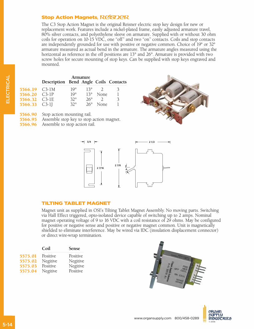
Armature Description BendAngleCoils Contacts
C3-1M 19° 13° 2 3 C3-1P 19° 13° None 1 C3-1E 32° 26° 2 3 C3-1J 32° 26° None 1
Stop action mounting rail. Assemble stop key to stop action magnet. Assemble to stop action rail.
Stop Action Magnets, reiSner
The C3 Stop Action Magnet is the original Reisner electric stop key design for new or replacement work. Features include a nickel-plated frame, easily adjusted armature travel, 80% silver contacts, and polyethylene sleeve on armature. Supplied with or without 30 ohm coils for operation on 10-15 VDC, one “off” and two “on” contacts. Coils and stop contacts are independently grounded for use with positive or negative common. Choice of 19° or 32° armature measured as actual bend in the armature. The armature angles measured using the horizontal as reference in the off positions are 13° and 26°. Armature is provided with two screw holes for secure mounting of stop keys. Can be supplied with stop keys engraved and mounted.
5566.195566.205566.325566.33
5566.905566.955566.96
tILtInG tABLet MAGnet
Magnet unit as supplied in OSI’s Tilting Tablet Magnet Assembly. No moving parts. Switching via Hall Effect triggered, opto-isolated device capable of switching up to 2 amps. Nominal magnet operating voltage of 9 to 16 VDC with a coil resistance of 29 ohms. May be configured for positive or negative sense and positive or negative magnet common. Unit is magnetically shielded to eliminate interference. May be wired via IDC (insulation displacement connector) or direct wire-wrap termination.
Coil Sense
Positive Positive Negitive Negitive Positive Negitive Negitive Positive
5575.015575.025575.035575.04
ELECTRICAL
5-�5 © 2006
800/458-0289 www.organsupply.com
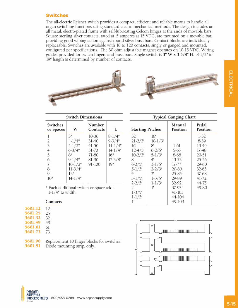
Switches Number Manual Pedal orSpaces W Contacts L StartingPitches Position Position
1 3" 10-30 8-1/4" 32' 16' 1-32 2 4-1/4" 31-40 9-3/4" 21-2/3' 10-1/3' 8-39 3 5-1/2" 41-50 11-1/4" 16' 8' 1-61 13-44 4 6-3/4" 51-70 14-1/4" 12-4/5' 6-2/5' 5-65 17-48 5 8" 71-80 16" 10-2/3' 5-1/3' 8-68 20-51 6 9-1/4" 81-90 17-3/8" 8' 4' 13-73 25-56 7 10-1/2" 91-100 19" 6-2/5' 3-1/5' 17-77 29-60 8 11-3/4" 5-1/3' 2-2/3' 20-80 32-63 9 13" 4' 2' 25-85 37-68 10* 14-1/4" 3-1/5' 1-3/5' 29-89 41-72 2-2/3' 1-1/3' 32-92 44-75 * Each additional switch or space adds 2' 1' 37-97 49-80 1-1/4" to width. 1-3/5' 41-101 1-1/3' 44-104 Contacts 1' 49-109
12 25 32 4961 73
Replacement 10 finger blocks for switches.Diode mounting strip, only.
5601.125601.255601.325601.495601.615601.73
5601.905601.91
Switches
The all-electric Reisner switch provides a compact, efficient and reliable means to handle all organ switching functions using standard electro-mechanical methods. The design includes an all metal, electro-plated frame with self-lubricating Celcon hinges at the ends of movable bars. Square sterling silver contacts, rated at .5 amperes at 15 VDC, are mounted on a movable bar, providing good wiping action against round silver buss bars. Contact blocks are individually replaceable. Switches are available with 10 to 120 contacts, singly or ganged and mounted, configured per specifications. The 30 ohm adjustable magnet operates on 10-15 VDC. Wiring guides provided for switch fingers and buss bars. Single switch is 3"Wx3-5/8"H.8-1/2" to 19" length is determined by number of contacts.
SwitchDimensions TypicalGangingChart
ELECTRICAL
5-�� © 2006
www.organsupply.com 800/458-0289
Diodes
Diodes are used for arc suppression and circuit isolation. Amperes Use
1N4004 1 General purpose 1N4007 2.5 Heavy duty use
5800.005801.00
electrical tape
General purpose or fire retardant, cloth backed friction tape is used as wire harness wrap. Fire retardant tape is UL approved.
Size Use
3/4" x 100' General purpose 3/4" x 100' Fire retardant- (UL approved)3/4” x 100’ Flame Retardant- (not UL approved)
5810.015810.02
5810.03
electrical Contact Cleaner
Contact cleaner and lubricant spray removes contaminants such as grease, dirt, dust, and oxidation residue and leaves behind a microscopic corrosion-proof film. 11 oz. spray can comes complete with extension tube. Nonflammable.
5820.00
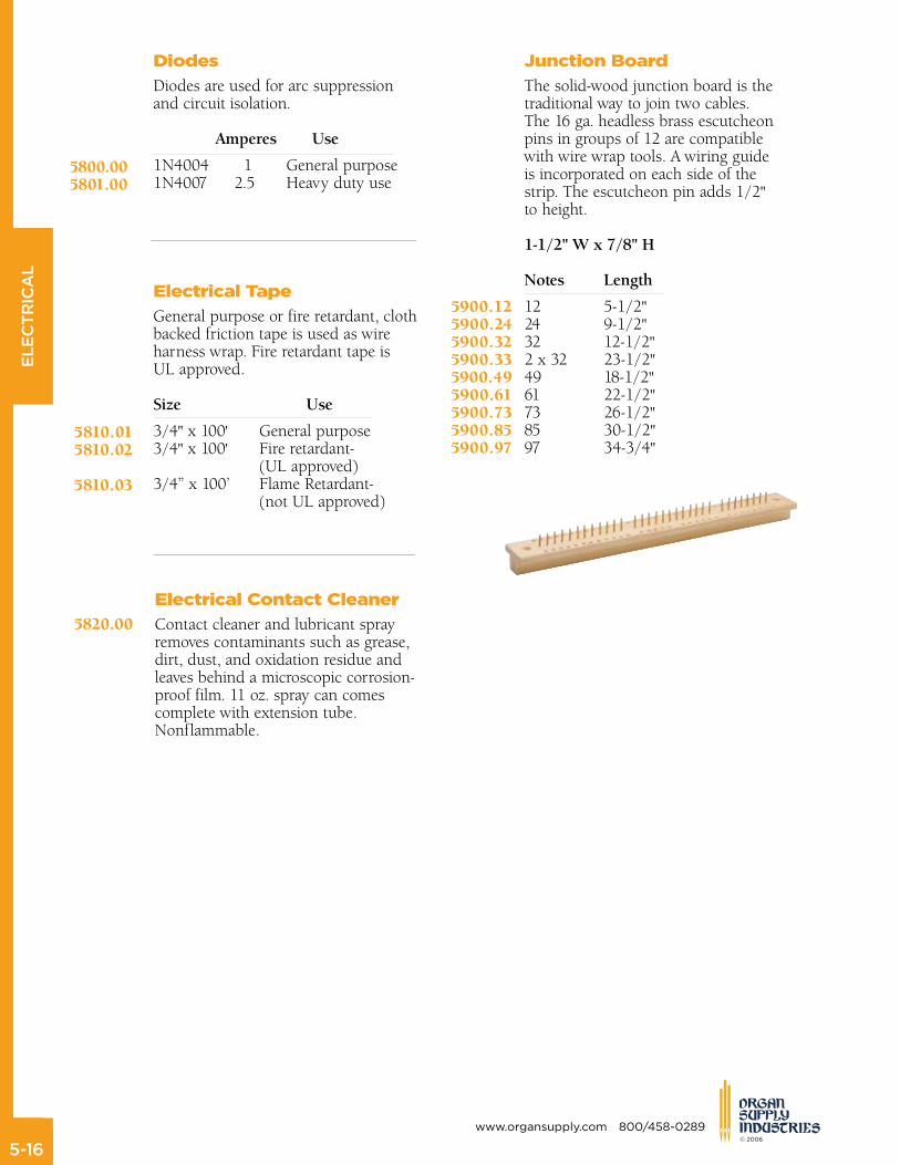
Junction Board
The solid-wood junction board is the traditional way to join two cables. The 16 ga. headless brass escutcheon pins in groups of 12 are compatible with wire wrap tools. A wiring guide is incorporated on each side of the strip. The escutcheon pin adds 1/2" to height.
1-1/2"Wx7/8"H Notes Length
12 5-1/2" 24 9-1/2" 32 12-1/2" 2 x 32 23-1/2" 49 18-1/2" 61 22-1/2" 73 26-1/2" 85 30-1/2" 97 34-3/4"
5900.125900.245900.325900.335900.495900.615900.735900.855900.97

ELECTRICAL
5-�� © 2006
800/458-0289 www.organsupply.com
Junction Plate
The brass junction plate is a convenient terminal strip for organ commons. It is bored and tapped for ten No. 8 brass screws and two mounting holes. Appropriate screws, copper washers, and mounting spacers are furnished.
1/16"Tx1/2"Wx6"L
5910.00
Lacing Cord
Designed for lacing cables, this waxed nylon cord comes in 1 lb. spools.
5920.00
Insulated Staples
Used to secure small cables and main wires. 100 pcs. per box. No. Size
3 3/16" x 3/4" 5 1/4" x 5/8" 6 1/4" x 3/4" 7 1/4" x 7/8"
5930.035930.055930.065930.07
ELECTRICAL
5-�� © 2006
www.organsupply.com 800/458-0289
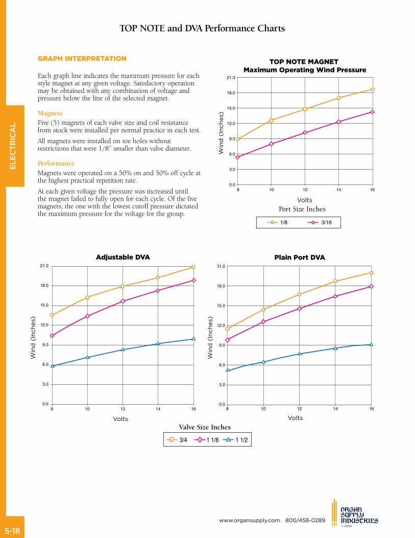
TOPNOTEandDVAPerformanceCharts
ValveSizeInches
Adjustable DVA
Wind (Inches)
Wind (Inches)
Volts
Plain Port DVA
Volts
tOP nOte MAGnet Maximum Operating Wind Pressure
Wind (Inches)
Volts
PortSizeInches
GRAPH InteRPRetAtIOn
Each graph line indicates the maximum pressure for each style magnet at any given voltage. Satisfactory operation may be obtained with any combination of voltage and pressure below the line of the selected magnet.
MagnetsFive (5) magnets of each valve size and coil resistance from stock were installed per normal practice in each test.
All magnets were installed on toe holes without restrictions that were 1/8” smaller than valve diameter.
PerformanceMagnets were operated on a 50% on and 50% off cycle at the highest practical repetition rate.
At each given voltage the pressure was increased until the magnet failed to fully open for each cycle. Of the five magnets, the one with the lowest cutoff pressure dictated the maximum pressure for the voltage for the group.

ELECTRICAL
5-�� © 2006
800/458-0289 www.organsupply.com
10
10
Win
d (I
nche
s)
Volts
1-1/4
6
4
2
012 14 16
8
“
601PerformanceCharts
- 150 Ohm - 90 Ohm - 60 Ohm - 40 Ohm
10
25
30
35W
ind
(Inc
hes)
Volts
5/8”
15
10
5
012 14 16
20
10
Win
d (I
nche
s)
Volts
7/8
15
10
5
012 14 16
20
“
10
10
12
Win
d (I
nche
s)
Volts
1-1/8
6
4
2
012 14 16
8
“
10
25
Win
d (I
nche
s)
Volts
3/4”
15
10
5
012 14 16
20
10
10
12
14
16
Win
d (I
nche
s)
Volts
1”
6
4
2
012 14 16
8
Top Related