


Languages
Pages
Legal


ABI
™
3948
Nucleic Acid Synthesis and Purification System
Reference Manual

© Copyright 2001, 2011 Applied Biosystems. All rights reserved.
For Research Use Only. Not for use in diagnostic procedures.
ABI P
RISM
and the ABI P
RISM
design, Applied Biosystems, FastPhoramidite, ONESTEP, OPC, Phosphalink, and POLYPORE are registered trademarksof Applera Corporation or its subsidiaries in the U.S. and certain other countries.
ABI, CATALYST, LV40, and PDQ are trademarks of Applera Corporation or its subsidiaries in the U.S. and certain other countries.
All other trademarks are the sole property of their respective owners.
Contents
iii
1 Introduction to the Reference Manual. . . . . . . . . . . . . . . . . . . . . 1-1
In This Chapter . . . . . . . . . . . . . . . . . . . . . . . . . . . . . . . . . . . . . . . . . . . . . . . . . . . . . . . . . . . . . . 1-1
Using This Manual . . . . . . . . . . . . . . . . . . . . . . . . . . . . . . . . . . . . . . . . . . . . . . . . . . . . . . . . . . . 1-2
User Bulletins . . . . . . . . . . . . . . . . . . . . . . . . . . . . . . . . . . . . . . . . . . . . . . . . . . . . . . . . . . . . . . . 1-4
Key Terms Defined . . . . . . . . . . . . . . . . . . . . . . . . . . . . . . . . . . . . . . . . . . . . . . . . . . . . . . . . . . . 1-4
2 System Description . . . . . . . . . . . . . . . . . . . . . . . . . . . . . . . . . . . . 2-1
In This Chapter . . . . . . . . . . . . . . . . . . . . . . . . . . . . . . . . . . . . . . . . . . . . . . . . . . . . . . . . . . . . . . 2-1
Section 1 - General Description of Processes, System Control, and Hardware . . . . . . . . . 2-2
Basic Instrument Features . . . . . . . . . . . . . . . . . . . . . . . . . . . . . . . . . . . . . . . . . . . . . . . . . . . . . 2-3
General Description of Instrument Chemistry . . . . . . . . . . . . . . . . . . . . . . . . . . . . . . . . . . . . . . 2-4
System Control and Sensing. . . . . . . . . . . . . . . . . . . . . . . . . . . . . . . . . . . . . . . . . . . . . . . . . . . . 2-6
Hardware Description Overview . . . . . . . . . . . . . . . . . . . . . . . . . . . . . . . . . . . . . . . . . . . . . . . . 2-7
Section 2 - More Details of System Hardware . . . . . . . . . . . . . . . . . . . . . . . . . . . . . . . . . . . 2-8
OneStep Column and Column Turntable . . . . . . . . . . . . . . . . . . . . . . . . . . . . . . . . . . . . . . . . . . 2-9
Jaw Mechanism . . . . . . . . . . . . . . . . . . . . . . . . . . . . . . . . . . . . . . . . . . . . . . . . . . . . . . . . . . . . 2-11
Pressure Regulation and Control (PRC) Module . . . . . . . . . . . . . . . . . . . . . . . . . . . . . . . . . . . 2-12
Synthesis Module . . . . . . . . . . . . . . . . . . . . . . . . . . . . . . . . . . . . . . . . . . . . . . . . . . . . . . . . . . . 2-13
Cleavage Module . . . . . . . . . . . . . . . . . . . . . . . . . . . . . . . . . . . . . . . . . . . . . . . . . . . . . . . . . . . 2-15
Deprotection Module . . . . . . . . . . . . . . . . . . . . . . . . . . . . . . . . . . . . . . . . . . . . . . . . . . . . . . . . 2-16
Purification Module . . . . . . . . . . . . . . . . . . . . . . . . . . . . . . . . . . . . . . . . . . . . . . . . . . . . . . . . . 2-18
Quantitation Module. . . . . . . . . . . . . . . . . . . . . . . . . . . . . . . . . . . . . . . . . . . . . . . . . . . . . . . . . 2-20
Sample Collection Module . . . . . . . . . . . . . . . . . . . . . . . . . . . . . . . . . . . . . . . . . . . . . . . . . . . . 2-21
3 Automated DNA Synthesis Chemistry . . . . . . . . . . . . . . . . . . . . . 3-1
In This Chapter . . . . . . . . . . . . . . . . . . . . . . . . . . . . . . . . . . . . . . . . . . . . . . . . . . . . . . . . . . . . . . 3-1
Section 1 – DNA Chemistry . . . . . . . . . . . . . . . . . . . . . . . . . . . . . . . . . . . . . . . . . . . . . . . . . . 3-2
DNA Synthesis Overview. . . . . . . . . . . . . . . . . . . . . . . . . . . . . . . . . . . . . . . . . . . . . . . . . . . . . . 3-3
Overview of the Phosphoramidite Method of Synthesis . . . . . . . . . . . . . . . . . . . . . . . . . . . . . . 3-6
Detritylation Chemistry Reactions . . . . . . . . . . . . . . . . . . . . . . . . . . . . . . . . . . . . . . . . . . . . . . . 3-9
Coupling Chemistry Reactions. . . . . . . . . . . . . . . . . . . . . . . . . . . . . . . . . . . . . . . . . . . . . . . . . 3-11
Capping Chemistry Reactions . . . . . . . . . . . . . . . . . . . . . . . . . . . . . . . . . . . . . . . . . . . . . . . . . 3-13
Oxidation Chemistry Reactions . . . . . . . . . . . . . . . . . . . . . . . . . . . . . . . . . . . . . . . . . . . . . . . . 3-15
DNA Cleavage and Deprotection . . . . . . . . . . . . . . . . . . . . . . . . . . . . . . . . . . . . . . . . . . . . . . . 3-16
References . . . . . . . . . . . . . . . . . . . . . . . . . . . . . . . . . . . . . . . . . . . . . . . . . . . . . . . . . . . . . . . . 3-18

iv
Section 2 – Oligonucleotide Purification, Quantitation, and Storage . . . . . . . . . . . . . . . 3-19
DNA Purification . . . . . . . . . . . . . . . . . . . . . . . . . . . . . . . . . . . . . . . . . . . . . . . . . . . . . . . . . . . 3-20
Overview of Oligonucleotide Quantitation . . . . . . . . . . . . . . . . . . . . . . . . . . . . . . . . . . . . . . . 3-22
Measurement of ODU and Concentration . . . . . . . . . . . . . . . . . . . . . . . . . . . . . . . . . . . . . . . . 3-23
Storage of the Oligonucleotide . . . . . . . . . . . . . . . . . . . . . . . . . . . . . . . . . . . . . . . . . . . . . . . . 3-27
Alternative Chemistries . . . . . . . . . . . . . . . . . . . . . . . . . . . . . . . . . . . . . . . . . . . . . . . . . . . . . . 3-28
4 Overview of Software Commands . . . . . . . . . . . . . . . . . . . . . . . . 4-1
In This Chapter . . . . . . . . . . . . . . . . . . . . . . . . . . . . . . . . . . . . . . . . . . . . . . . . . . . . . . . . . . . . . 4-1
Section 1 – File and Edit Menus . . . . . . . . . . . . . . . . . . . . . . . . . . . . . . . . . . . . . . . . . . . . . . 4-2
Overview of File Menu Commands. . . . . . . . . . . . . . . . . . . . . . . . . . . . . . . . . . . . . . . . . . . . . . 4-3
New Synthesis Order Command . . . . . . . . . . . . . . . . . . . . . . . . . . . . . . . . . . . . . . . . . . . . . . . . 4-5
Open Command . . . . . . . . . . . . . . . . . . . . . . . . . . . . . . . . . . . . . . . . . . . . . . . . . . . . . . . . . . . . . 4-8
Open Synthesizer Command . . . . . . . . . . . . . . . . . . . . . . . . . . . . . . . . . . . . . . . . . . . . . . . . . . 4-10
Other File Menu Commands . . . . . . . . . . . . . . . . . . . . . . . . . . . . . . . . . . . . . . . . . . . . . . . . . . 4-13
Overview of Edit Menu Commands . . . . . . . . . . . . . . . . . . . . . . . . . . . . . . . . . . . . . . . . . . . . 4-17
Section 2 – Synthesizer and Window Menus . . . . . . . . . . . . . . . . . . . . . . . . . . . . . . . . . . . 4-20
Overview of Synthesizer Commands . . . . . . . . . . . . . . . . . . . . . . . . . . . . . . . . . . . . . . . . . . . 4-21
Abort Command . . . . . . . . . . . . . . . . . . . . . . . . . . . . . . . . . . . . . . . . . . . . . . . . . . . . . . . . . . . 4-22
Interrupt Command . . . . . . . . . . . . . . . . . . . . . . . . . . . . . . . . . . . . . . . . . . . . . . . . . . . . . . . . . 4-22
Resume Command. . . . . . . . . . . . . . . . . . . . . . . . . . . . . . . . . . . . . . . . . . . . . . . . . . . . . . . . . . 4-22
Pause After Command . . . . . . . . . . . . . . . . . . . . . . . . . . . . . . . . . . . . . . . . . . . . . . . . . . . . . . . 4-23
Synchronize Clocks Command . . . . . . . . . . . . . . . . . . . . . . . . . . . . . . . . . . . . . . . . . . . . . . . . 4-24
Change Password Command . . . . . . . . . . . . . . . . . . . . . . . . . . . . . . . . . . . . . . . . . . . . . . . . . . 4-25
Change Name Command. . . . . . . . . . . . . . . . . . . . . . . . . . . . . . . . . . . . . . . . . . . . . . . . . . . . . 4-26
Instrument Preferences Command. . . . . . . . . . . . . . . . . . . . . . . . . . . . . . . . . . . . . . . . . . . . . . 4-27
Window Menu . . . . . . . . . . . . . . . . . . . . . . . . . . . . . . . . . . . . . . . . . . . . . . . . . . . . . . . . . . . . . 4-30
Section 3 – RunFiles, Sample Labeling, Synthesis Order and Multi-Order Files . . . . . 4-31
RunFiles. . . . . . . . . . . . . . . . . . . . . . . . . . . . . . . . . . . . . . . . . . . . . . . . . . . . . . . . . . . . . . . . . . 4-32
Sample Labeling Feature . . . . . . . . . . . . . . . . . . . . . . . . . . . . . . . . . . . . . . . . . . . . . . . . . . . . . 4-33
Label View Information . . . . . . . . . . . . . . . . . . . . . . . . . . . . . . . . . . . . . . . . . . . . . . . . . . . . . . 4-36
About Synthesis Orders . . . . . . . . . . . . . . . . . . . . . . . . . . . . . . . . . . . . . . . . . . . . . . . . . . . . . . 4-38
Multi-Order Files . . . . . . . . . . . . . . . . . . . . . . . . . . . . . . . . . . . . . . . . . . . . . . . . . . . . . . . . . . . 4-41
5 Communication View and Operational Views . . . . . . . . . . . . . . . 5-1
In This Chapter . . . . . . . . . . . . . . . . . . . . . . . . . . . . . . . . . . . . . . . . . . . . . . . . . . . . . . . . . . . . . 5-1
Section 1 - General Information about Operational Synthesizer Views . . . . . . . . . . . . . . 5-2
About the Synthesizer Window . . . . . . . . . . . . . . . . . . . . . . . . . . . . . . . . . . . . . . . . . . . . . . . . . 5-4
Communication View . . . . . . . . . . . . . . . . . . . . . . . . . . . . . . . . . . . . . . . . . . . . . . . . . . . . . . . . 5-6
Run Setup View . . . . . . . . . . . . . . . . . . . . . . . . . . . . . . . . . . . . . . . . . . . . . . . . . . . . . . . . . . . . . 5-7
Run Protocol View. . . . . . . . . . . . . . . . . . . . . . . . . . . . . . . . . . . . . . . . . . . . . . . . . . . . . . . . . . . 5-9

v
Monitor Chemistry View . . . . . . . . . . . . . . . . . . . . . . . . . . . . . . . . . . . . . . . . . . . . . . . . . . . . . 5-11
Monitor Instrument. . . . . . . . . . . . . . . . . . . . . . . . . . . . . . . . . . . . . . . . . . . . . . . . . . . . . . . . . . 5-15
Liquid Sensors . . . . . . . . . . . . . . . . . . . . . . . . . . . . . . . . . . . . . . . . . . . . . . . . . . . . . . . . . . . . . 5-16
Monitor Run View . . . . . . . . . . . . . . . . . . . . . . . . . . . . . . . . . . . . . . . . . . . . . . . . . . . . . . . . . . 5-19
Section 2 - Using the Run Setup View and Extending a Run . . . . . . . . . . . . . . . . . . . . . . 5-20
Importing Synthesis Orders . . . . . . . . . . . . . . . . . . . . . . . . . . . . . . . . . . . . . . . . . . . . . . . . . . . 5-21
Selecting Orders for the Next Run . . . . . . . . . . . . . . . . . . . . . . . . . . . . . . . . . . . . . . . . . . . . . . 5-23
Synthesis Order Information . . . . . . . . . . . . . . . . . . . . . . . . . . . . . . . . . . . . . . . . . . . . . . . . . . 5-24
Assigning Chemistry and AutoSorting . . . . . . . . . . . . . . . . . . . . . . . . . . . . . . . . . . . . . . . . . . . . . . . . . . . . . . . . . . . . . . . 5-25
Bottle Usage . . . . . . . . . . . . . . . . . . . . . . . . . . . . . . . . . . . . . . . . . . . . . . . . . . . . . . . . . . . . . . . 5-27
Using the Load Display . . . . . . . . . . . . . . . . . . . . . . . . . . . . . . . . . . . . . . . . . . . . . . . . . . . . . . 5-28
Extending a Run . . . . . . . . . . . . . . . . . . . . . . . . . . . . . . . . . . . . . . . . . . . . . . . . . . . . . . . . . . . . 5-30
6 Synthesizer Views Supporting Operation . . . . . . . . . . . . . . . . . . . 6-1
In This Chapter . . . . . . . . . . . . . . . . . . . . . . . . . . . . . . . . . . . . . . . . . . . . . . . . . . . . . . . . . . . . . . 6-1
Section 1 – Non-Cycle Operational Support Views . . . . . . . . . . . . . . . . . . . . . . . . . . . . . . . 6-2
Manual Control View . . . . . . . . . . . . . . . . . . . . . . . . . . . . . . . . . . . . . . . . . . . . . . . . . . . . . . . . . 6-3
Power Fail View . . . . . . . . . . . . . . . . . . . . . . . . . . . . . . . . . . . . . . . . . . . . . . . . . . . . . . . . . . . . . 6-6
Instrument Test View . . . . . . . . . . . . . . . . . . . . . . . . . . . . . . . . . . . . . . . . . . . . . . . . . . . . . . . . . 6-7
B+ Tet Calibration . . . . . . . . . . . . . . . . . . . . . . . . . . . . . . . . . . . . . . . . . . . . . . . . . . . . . . . . . . . 6-8
Reagent Utilization Table View . . . . . . . . . . . . . . . . . . . . . . . . . . . . . . . . . . . . . . . . . . . . . . . . . 6-9
Section 2 – Editing Cycle and Procedure Views . . . . . . . . . . . . . . . . . . . . . . . . . . . . . . . . . 6-11
Edit Cycle and Procedure Interface . . . . . . . . . . . . . . . . . . . . . . . . . . . . . . . . . . . . . . . . . . . . . 6-12
Edit Synthesis Cycle View . . . . . . . . . . . . . . . . . . . . . . . . . . . . . . . . . . . . . . . . . . . . . . . . . . . . 6-17
Edit Cleavage Cycle View . . . . . . . . . . . . . . . . . . . . . . . . . . . . . . . . . . . . . . . . . . . . . . . . . . . . 6-18
Edit Purification Cycle View . . . . . . . . . . . . . . . . . . . . . . . . . . . . . . . . . . . . . . . . . . . . . . . . . . 6-19
Edit Begin Procedure View. . . . . . . . . . . . . . . . . . . . . . . . . . . . . . . . . . . . . . . . . . . . . . . . . . . . 6-20
Edit End Procedure View . . . . . . . . . . . . . . . . . . . . . . . . . . . . . . . . . . . . . . . . . . . . . . . . . . . . . 6-21
Edit Bottle Procedure View . . . . . . . . . . . . . . . . . . . . . . . . . . . . . . . . . . . . . . . . . . . . . . . . . . . 6-22
Misc (Miscellaneous) Procedures View . . . . . . . . . . . . . . . . . . . . . . . . . . . . . . . . . . . . . . . . . . 6-23
A Valves and Functions . . . . . . . . . . . . . . . . . . . . . . . . . . . . . . . . . .A-1
In This Appendix . . . . . . . . . . . . . . . . . . . . . . . . . . . . . . . . . . . . . . . . . . . . . . . . . . . . . . . . . . . A-1
Information on ABI 3948 System Chemistry Terminology . . . . . . . . . . . . . . . . . . . . . . . . . . . A-3
Valves . . . . . . . . . . . . . . . . . . . . . . . . . . . . . . . . . . . . . . . . . . . . . . . . . . . . . . . . . . . . . . . . . . . . A-5
Overview of Functions . . . . . . . . . . . . . . . . . . . . . . . . . . . . . . . . . . . . . . . . . . . . . . . . . . . . . . . A-7
Valve Functions . . . . . . . . . . . . . . . . . . . . . . . . . . . . . . . . . . . . . . . . . . . . . . . . . . . . . . . . . . . A-10
Sensors . . . . . . . . . . . . . . . . . . . . . . . . . . . . . . . . . . . . . . . . . . . . . . . . . . . . . . . . . . . . . . . . . . A-11
Valve Functions by Functional Category . . . . . . . . . . . . . . . . . . . . . . . . . . . . . . . . . . . . . . . . A-15
Non-Valve Hardware Functions . . . . . . . . . . . . . . . . . . . . . . . . . . . . . . . . . . . . . . . . . . . . . . . A-23

vi
B ABI 3948 System Special Functions . . . . . . . . . . . . . . . . . . . . . . B-1
In This Appendix . . . . . . . . . . . . . . . . . . . . . . . . . . . . . . . . . . . . . . . . . . . . . . . . . . . . . . . . . . . . B-1
Overview of Special Functions . . . . . . . . . . . . . . . . . . . . . . . . . . . . . . . . . . . . . . . . . . . . . . . . . B-2
Listing of Special Functions . . . . . . . . . . . . . . . . . . . . . . . . . . . . . . . . . . . . . . . . . . . . . . . . . . . B-5
C Cycles, Procedures, and System Messages . . . . . . . . . . . . . . . . . C-1
In This Appendix . . . . . . . . . . . . . . . . . . . . . . . . . . . . . . . . . . . . . . . . . . . . . . . . . . . . . . . . . . . . C-1
3948 Chemistry . . . . . . . . . . . . . . . . . . . . . . . . . . . . . . . . . . . . . . . . . . . . . . . . . . . . . . . . . . . . . C-2
The Standard Synthesis Cycle . . . . . . . . . . . . . . . . . . . . . . . . . . . . . . . . . . . . . . . . . . . . . . . . . . C-3
The Standard Cleavage/Deprotection Cycle . . . . . . . . . . . . . . . . . . . . . . . . . . . . . . . . . . . . . . . C-9
The Standard Purification Cycle . . . . . . . . . . . . . . . . . . . . . . . . . . . . . . . . . . . . . . . . . . . . . . . C-18
Procedures . . . . . . . . . . . . . . . . . . . . . . . . . . . . . . . . . . . . . . . . . . . . . . . . . . . . . . . . . . . . . . . . C-32
System Messages . . . . . . . . . . . . . . . . . . . . . . . . . . . . . . . . . . . . . . . . . . . . . . . . . . . . . . . . . . . C-38
D 3948 System Function List and Other Cycles . . . . . . . . . . . . . . . D-1
In This Appendix . . . . . . . . . . . . . . . . . . . . . . . . . . . . . . . . . . . . . . . . . . . . . . . . . . . . . . . . . . . . D-1
ABI 3948 System Function List . . . . . . . . . . . . . . . . . . . . . . . . . . . . . . . . . . . . . . . . . . . . . . . . D-2
The Purification Dye Cycle . . . . . . . . . . . . . . . . . . . . . . . . . . . . . . . . . . . . . . . . . . . . . . . . . . . D-39
The Purification Biotin Cycle . . . . . . . . . . . . . . . . . . . . . . . . . . . . . . . . . . . . . . . . . . . . . . . . . D-48
E Instrument Plumbing Diagram . . . . . . . . . . . . . . . . . . . . . . . . . . E-1
F Limited Warranty Statement. . . . . . . . . . . . . . . . . . . . . . . . . . . . . F-1
Index

Introduction to the Reference Manual 1-1
Introduction to the Reference Manual 1
In This Chapter
User and ReferenceManuals
The
ABI
3948 System Reference Manual
is one of two manuals in the document set supporting the ABI
™
3948 Nucleic Acid Synthesis and Purification System. The first manual in the set, the
ABI
3948
System User’s Manual
, is intended for daily operation, while this reference manual presents detailed information needed to fully understand, use, and maintain the instrument.
Topics Covered
This chapter contains the following topics:
Topic See page
Using This Manual 1-2
Contents of the Manual 1-2
User Bulletins 1-4
Purpose of User Bulletins 1-4
Key Terms Defined 1-4
Table of Key Terms 1-4
1
1-2 Introduction to the Reference Manual
Using This Manual
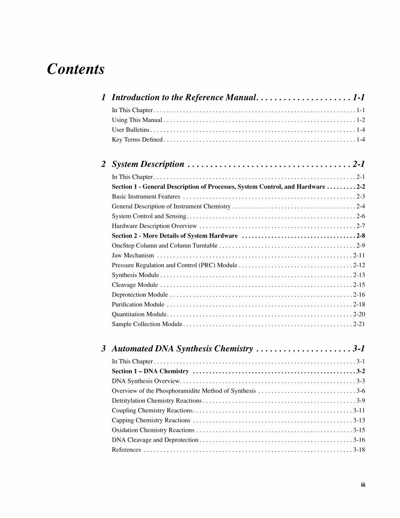
Contents of theManual
This manual contains five chapters and several appendices.
Chapter/Appendix Title Types of Information
1 Introduction to the Reference Manual/ Instrument
�
Purposes of User and Reference manuals
�
Information about safety and user bulletins
�
Description of the ABI 3948 System
2 System Description
�
Overview of how the system is controlled
�
Descriptions of the six modules:
– Synthesis
– Cleavage
– Deprotection
– Purification
– Quantitation
– Sample Collection
3 Chemistry for Automated DNA Chemistry
�
DNA synthesis overview
�
Description of Cleavage and Deprotection
�
Quantitation of the Oligonucleotide
�
Purification
�
Storage of the Oligonucleotide
4 Overview of System Commands
Detailed command information covering the following menus:
�
File menu
�
Open Synthesizer menu
�
Edit menu
�
Synthesizer menu
�
Window menu
5 Communication View and Operational Views
Detailed information covering the following:
�
Synthesizer Window
�
Communication view
�
Run Setup view
�
Run Protocol view
�
Monitor Chemistry view
�
Monitor Instrument view
�
Monitor Run view

Introduction to the Reference Manual 1-3
6 Other Synthesizer Views
Detailed information covering the following:
�
MISC (Miscellaneous) Procedures view
�
Manual Control view
�
Power Fail view
�
Instrument Test view
�
B+Tet Calibration view
�
Reagent Utilization Table view
�
Editing Cycle and Procedure views
A Valves and Functions
�
Default Contents of the B+ Tet Calibration View
�
Default Contents of the Reagent Utilization View
B Cycles, Procedures, and System Messages
Detailed information on the following:
�
Standard Synthesis Cycle
�
Standard Cleavage/Deprotection Cycle
�
Standard Purification Cycle
�
Procedures
�
System Messages
C 3948 System Function List and Other Cycles
�
3948 System Function List
�
Purification Dye Cycle
�
Purification Biotin Cycle
Chapter/Appendix Title Types of Information

1-4 Introduction to the Reference Manual
User Bulletins
Purpose of UserBulletins
User Bulletins (UBs) contain technical information that is essential to ABI 3948 instrument operation and related laboratory techniques. UBs are the quickest way to ensure that you have current information. They are produced periodically and mailed to you as they become available.
Please read the UBs before operating your ABI 3948 instrument. Current UBs are found under their own tab at the end of the
ABI 3948 Instrument Reference Manua
l.
Key Terms Defined
Table of Key Terms
The following table lists the key terms needed for operation of the 3948.:
Term Definition
3948Control Views
Protocol Contains the three chemistry cycles needed to produce an oligonucleotide:
�
Synthesis cycle
�
Cleavage cycle
�
Purification cycle
When new chemistry cycles are available, you can assign them to a new protocol using the Run Protocol view. For more information on creating a new protocol with your own cycles, see Chapter 6 of this manual.
Begin and End Procedures
These procedures, chosen during Run Setup, are run before and after oligonucleotide production. If you create a new protocol with your own cycles, you may need to create revised versions of these procedures (see Chapter 6 for information on revising these procedures).
Commands
Abort Immediately terminates execution of a run or Manual Control action in progress.
Interrupt Halts the instrument at the first safe step for all active chemistries (synthesis, cleavage, purification, and procedures).
There are two ways to initiate an interrupt:
� Choose Interrupt from the Synthesizer menu
� Press the Interrupt button on the ABI 3948 Synthesizer Front Panel
If you use Interrupt to halt the instrument operation, use the Resume command from the Synthesizer menu to restart the instrument
Pause After Halts the instrument after the designated synthesis, allowing the user to extend the run or do a bottle change if necessary.
To initiate a Pause After, choose Pause After from the Synthesizer menu.

System Description 2-1
System Description 2
In This Chapter
Topics Covered This chapter provides a general description of instrument chemistry processes and hardware.
The chapter contains two sections:
Topic See page
General Description of Processes, System Control, and Hardware 2-2
More Details of System Hardware 2-8
2

2-2 System Description
Section 1 - General Description of Processes, System Control, and Hardware
Topics Covered This section provides a general description of instrument Chemistry and other processes, system control and sensing, and an overview of instrument hardware.
The section covers the following topics:
Basic Instrument Features 2-3
Automatic Oligonucleotide Production 2-3
Phosphoramidite Method of Synthesis 2-3
Pressure-Driven Chemical Delivery 2-3
Macintosh 3948Control Software 2-3
General Description of Instrument Chemistry 2-4
Automation of Chemistry Processes 2-4
The First Four Chemistry Processes 2-4
Quantitation 2-5
Sample Collection 2-5
System Control and Sensing 2-6
Introduction 2-6
Types of Storage 2-6
Electromechanical and Electrical Drivers 2-6
Gas Pressure Sensors/Sensor Drivers 2-6
Liquid Sensors 2-6
Hardware Description Overview 2-7
Types of Hardware Described 2-7

System Description 2-3
Basic Instrument Features
AutomaticOligonucleotide
Production
The ABI 3948 Nucleic Acid Synthesis and Purification system completely automatesthe entire process of oligonucleotide production: synthesis, cleavage, deprotection,purification, quantitation, and sample collection. When used as a system utilizing ABIreagents and columns, this instrument produces high quality synthetic DNA whileminimizing synthesis time and cost.
PhosphoramiditeMethod of Synthesis
The phosphoramidite method of oligonucleotide synthesis is used because of itsinherently high coupling efficiency and the stability of the starting materials. The 3´terminal nucleoside attached to a solid support, which is contained within a disposablecolumn (the OneStep™ column). Nucleoside bases are added one at a time to thesupport-bound DNA chain until the sequence is fully synthesized. Solid supportsynthesis allows excess reagents to be removed by filtration and eliminates the needfor purification between base additions.
Pressure-DrivenChemical Delivery
Applied Biosystems synthesizers use a pressure driven chemical delivery system todeliver reagents and solvents to a reaction column chamber (OneStep column).Reagent and solvent deliveries also rely on our zero-dead volume valves whichincrease reliability, eliminate cross-contamination and reduce cycle costs.
ABI 3948 SystemSoftware for
Macintosh
You can program cycles, functions, and procedures for use in the synthesizer from theABI 3948 system software for Macintosh computer. Once you download chemistryprotocols, an internal controller/driver within the synthesizer exercises real-timecontrol of the instrument. The ABI 3948 instrument can run preprogrammed protocolsor you can create customized cycles. The Macintosh software is also used to fill outthe Synthesis Orders used as sequence input for the instrument.

2-4 System Description
General Description of Instrument Chemistry
Automation ofChemistry Processes
The ABI™ 3948 DNA Synthesis and Purification system automates four processes of DNA chemistry (synthesis, cleavage, deprotection, and purification), and then quantitates and automatically collects the DNA product.
The synthesis, cleavage, and purification processes are implemented in three modules that operate concurrently to provide the high throughput capacity of the instrument—as many as 48 twenty-mer oligonucleotides per day of operation.
The First FourChemistry Processes
Three of the four chemistry processes (synthesis, cleavage, and purification) take place within the OneStep™ column as it moves between the three modules. The fourth process, deprotection, takes place outside the OneStep column in the deprotection coils between cleavage and purification.
I
Module Process
Synthesis module The first process occurs in the column while it is positioned at the Synthesis module. The OneStep column contains the 3´-terminal nucleoside, covalently attached to support material. The DNA chain is built by adding one base at a time to the support-bound nucleoside.
IMPORTANT You can synthesize crude oligonucleotides with the 5´ trityl group either on or off; you must synthesize purified oligonucleotides with the 5´ trityl group on.
Cleavage module During the second process of automated oligonucleotide production, the OneStep column is positioned at the Cleavage module and processed as follows:
a. In the Cleavage module a delivery of concentrated aqueous ammonium hydroxide cleaves the oligonucleotide from the support.
b. The DNA product in the ammonium hydroxide solution is then transferred to the Deprotection module for processing outside the column.
Deprotection module In the Deprotection module, protecting groups are removed from the oligonucleotide as the third process by heating the solution containing the oligonucleotide for one hour at 65 °C.
Purification module During the fourth DNA chemistry process, purification, the desired, full-length oligonucleotide is separated from failure sequences and other impurities at the Purification module.
Purification is performed as follows:
a. The deprotected product is passed in ammonium hydroxide through the support in the original OneStep column.
b. The tritylated, full-length oligonucleotide binds to the support in the column while detritylated failure sequences and other impurities are washed away.
c. Following detritylation, the DNA products are eluted from the OneStep column, using a solution of 20% acetonitrile in water

System Description 2-5
Quantitation In the fifth production process, the purified oligonucleotides are quantitated using a UV (ultraviolet) light detection system as follows.
� The product, in a 20% acetonitrile solution, passes through the detector as it is delivered to the sample collection module.
� The absorbance is reported in ODUs (Optical Density Units) and picomoles to indicate quantity.
Sample Collection Automated oligonucleotide production concludes with the collection of the DNA sample in the sample collection module:
� The sample collection tray contains 48 sample vials to allow unattended collection of 48 DNA samples.
� A septum sheet under the OligoRack™ cover minimizes evaporation from and contamination of the sample vials.
� Each of the sample vials, covered by a septum, holds the 1-mL DNA sample volume from a OneStep column obtained in either the deprotection or purification module. The vial septum is chemically inert to both 20% acetonitrile/H2O and ammonium hydroxide.

2-6 System Description
System Control and Sensing
Introduction The ABI™ 3948 DNA Synthesis and Purification System is controlled from a computer with the Macintosh-compatible ABI 3948 instrument operating software. A user programs the system through the computer which interacts with embedded software on the instrument.
Types of Storage Several types of memory storage are available on the instrument:
� The embedded software code allows real-time control via the Macintosh® computer.
� The 3948 boot ROM holds instrument-unique data such as the instrument serial number.
� Battery backed-up memory stores critical data, such as power-failure recovery information and any data that is not transferred to the Macintosh.
� Temporary memory is reserved for the proper and reliable operation of the instrument. It is possible to increase synthesizer memory to accommodate future upgrades.
Electromechanicaland Electrical
Drivers
The instrument contains a number of electromechanical drivers that control the process of oligonucleotide production:
� One of these, the driver for the OneStep column turntable, properly positions the OneStep columns in the jaw mechanisms.
� Another driver, for the jaw mechanism, engages and disengages the jaw module to ensure a leak-tight seal.
� Other driver mechanisms include: the deprotection heater driver, the sample collection driver, and valve drivers.
Gas PressureSensors/Sensor
Drivers
Gas pressure sensors ensure accurate pressure-regulated delivery rates. In addition to regulation of gas and liquid flows, sensor drivers monitor the following instrument operations:
� Maintenance of the battery supported memory
� Positioning and movement of the OneStep column turntable and the jaw mechanism
� Regulation of the deprotection system temperature
� Sample collection
� Regulation and usage of the pressure management system that provides automated leak test capability
� Valve driver power usage and load/no-load testing to detect solenoid shorts and disconnections
Liquid Sensors The instrument also has liquid sensors to ensure that adequate amounts of reagents are available and properly delivered during the run. Liquid sensors are shown in the figure on page 2-16.
System Description 2-7
Hardware Description Overview
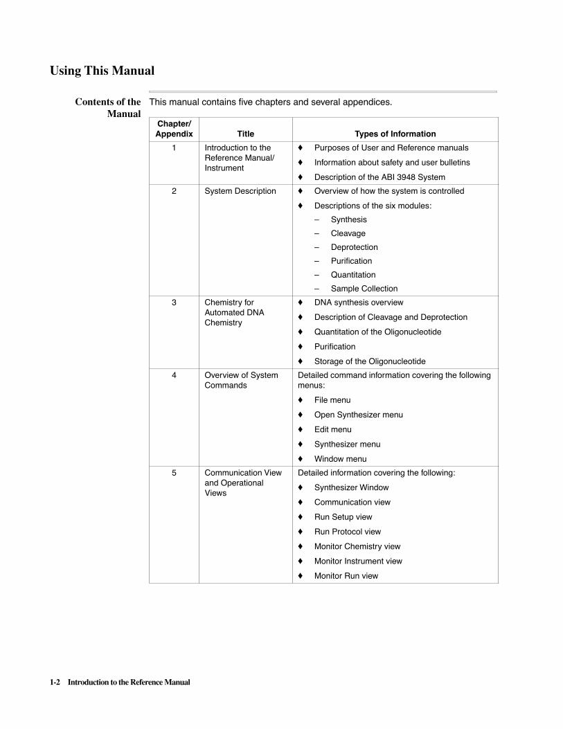
Types of HardwareDescribed
The following hardware is described in this chapter:
� OneStep™ Column and Column Turntable
Four types of OneStep columns are used. One for each of the starting monomers. The turntable is used to hold the columns and move them between the three chemistry jaw mechanisms (Synthesis, Cleavage, and Purification).
� Jaw Mechanism
This is the device used to clamp on the top and bottom of OneStep columns and provide flow paths for chemistry.
� Pressure Regulation and Control Module (PRC)
This module regulates and controls various pressures in the system.
� Synthesis Module
This module consists of the Synthesis jaw mechanism and associated plumbing.
� Cleavage Module
This module consists of the Cleavage jaw mechanism and associated plumbing.
� Deprotection Module
This module consists of deprotection coils and associated plumbing.
� Purification Module
This module consists of the Purification jaw mechanism and associated plumbing.
� Quantitation Module
This module consists of the UV detector and associated plumbing.
� Sample Collection Module
This module consists of the following three components:
– A mechanism and tray to hold the OligoRack/red rack and waste bottles.
The mechanism moves the tray to position tubes under the needle delivery system and extend the tray so that individual tubes can be removed.
– An OligoRack or optional red rack to hold 1.2-mL tubes.
– A needle delivery system to individually delivery synthesized or full length oligonucleotides to assigned positions.

2-8 System Description
Section 2 - More Details of System Hardware
This section provides general information on system hardware.
OneStep Column and Column Turntable 2-9
OneStep Columns and Column Turntable 2-9
OneStep Column Turntable 2-10
Jaw Mechanism 2-11
Uses of the Three Jaw Mechanisms 2-11
Pressure Regulation and Control (PRC) 2-12
Characteristics of Module 2-12
Synthesis Module 2-13
Location on the Plumbing Diagram 2-13
The Process of Synthesis 2-14
Cleavage Module 2-15
Location on the Plumbing Diagram 2-15
The Process of Cleavage 2-15
Deprotection Module 2-16
Deprotection Module Components 2-16
Location on the Plumbing Diagram 2-16
The Process of Deprotection 2-17
Purification Module 2-18
Location on the Plumbing Diagram 2-18
The Process of Purification 2-19
Quantitation Module 2-20
Description of UV Detection System 2-20
Sample Collection Module 2-21
Three Main Components 2-21
Two Types of Racks 2-22
Waste Containers 2-22
System Description 2-9
OneStep Column and Column Turntable
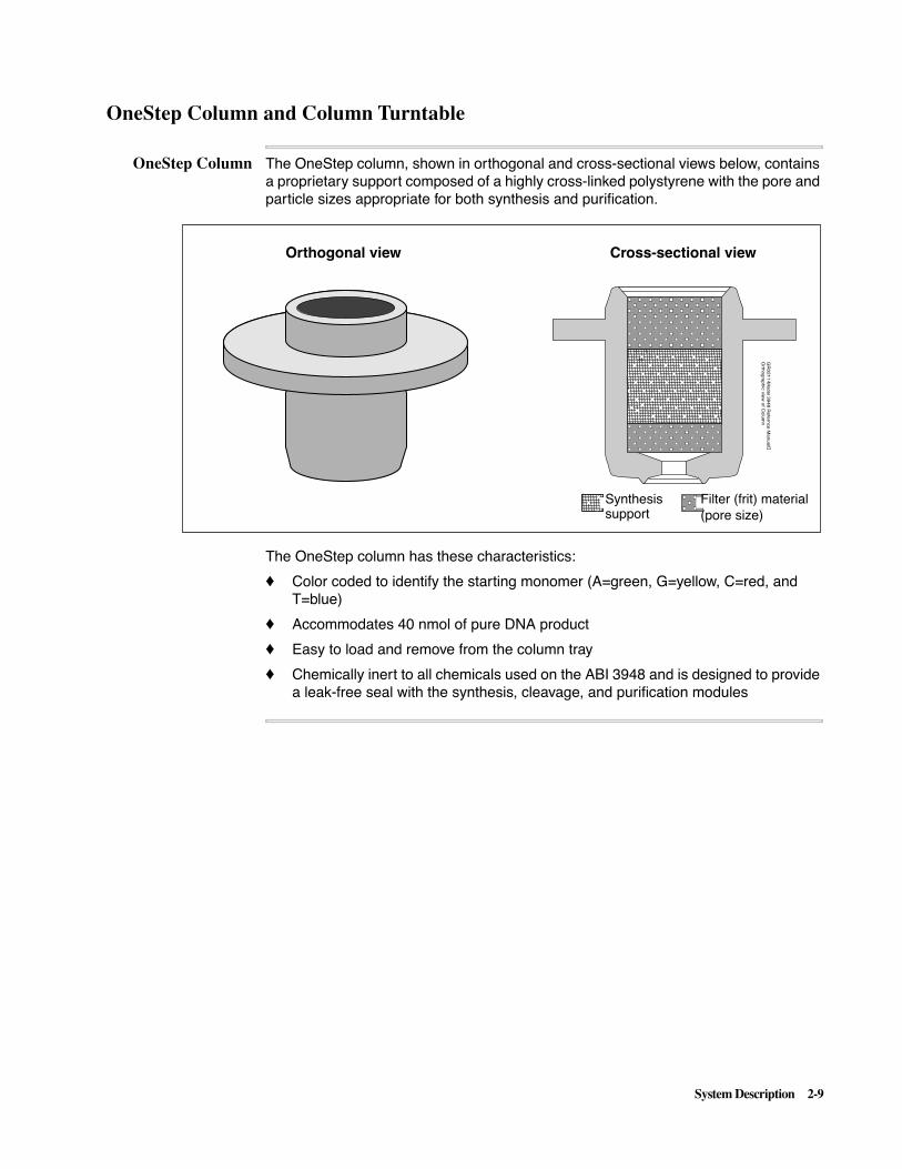
OneStep Column The OneStep column, shown in orthogonal and cross-sectional views below, contains a proprietary support composed of a highly cross-linked polystyrene with the pore and particle sizes appropriate for both synthesis and purification.
The OneStep column has these characteristics:
� Color coded to identify the starting monomer (A=green, G=yellow, C=red, and T=blue)
� Accommodates 40 nmol of pure DNA product
� Easy to load and remove from the column tray
� Chemically inert to all chemicals used on the ABI 3948 and is designed to provide a leak-free seal with the synthesis, cleavage, and purification modules
Orthogonal view Cross-sectional view
GR
02
11
•Mo
de
l 39
48
Re
fern
ce M
an
ua
l�O
rtho
gra
ph
ic view
of C
olu
mn
= Filter Material= Synthesis PowderSynthesis support
Filter (frit) material (pore size)

2-10 System Description
OneStep ColumnTurntable
The OneStep column turntable, shown below, does the following:
� Positions the columns in the synthesis, cleavage, and purification modules to ensure that the jaw mechanisms at these modules form a leak-free seal.
� Holds 48 columns and is easy to load.
� Precisely indexes the position of each column on the turntable for software control of each step of chemical delivery.
Note For clarity, the turntable in the figure is shown pulled away from the three jaw mechanisms with which it is associated. As the turntable rotates, OneStep columns in all 48 positions are presented in turn to the three jaw mechanisms for reagent deliveries.

System Description 2-11
Jaw Mechanism
Uses of the ThreeJaw Mechanisms
The jaw mechanism, shown below, is used in conjunction with the OneStep columns and turntable to provide a leak-tight seal for the reagent/gas delivery system.
Three jaws, one for each of the three chemistry modules (synthesis, cleavage, and purification), operate independently so that you can perform all three chemistries concurrently. All wetted components used in the mechanism are chemically inert to all reagents used for synthesis, cleavage and purification.

2-12 System Description
Pressure Regulation and Control (PRC) Module
Characteristics ofModule
The PRC board assembly function:
� Provides accurate gas delivery, regulates pressure to ensure sufficient volumes of reagents, and closes down delivery at shut off.
� Is entirely controlled via firmware and software.
� Has 10 individually selectable valves with 3 outlet ports for each valve.
� Individually controls the pressure settings of each valve via software. The pressure can be variably set from 0 psig (off) and up to 12 psig.
Note All used outlet port have a check valve and un-used ports are plugged.
� Has the following pressure transducers:
– Ten low pressure transducers to enable monitoring of pressure in the “Monitor Instrument” View.
– One pressure transducer to monitor inlet gas pressure.

System Description 2-13
Synthesis Module
Location on thePlumbing Diagram
The Synthesis module is a station on the column turntable where synthesis is performed on up to three reaction cartridges at a time. The portion of the plumbing diagram containing the Synthesis module is shown below. Liquid sensors, like those indicated in the plumbing diagram, are shown on page 2-16. For the full instrument plumbing diagram, see Appendix E.

2-14 System Description
The Process ofSynthesis
Synthesis is performed by delivering phosphoramidites and reagents through a OneStep column while the column is clamped firmly in a jaw mechanism to ensure leak free delivery:
� Controlled quantities of reagents are supplied step-by-step to the module from reagent bottles by a system of valve blocks using positive-lift valves and gas/ liquid sensors.
� Phosphoramidites are supplied from 2-g bottles and reagents are supplied in the following bottle sizes:
– TCA (2L), ACN (4 L)
– Iodine (450 mL)
– Acetic Anhydride (450 mL)
– Tetrazole (450 mL)
– NMI (450 mL)
Reagent volumes correspond roughly to the rate at which they are consumed during synthesis.

System Description 2-15
Cleavage Module
Location on thePlumbing Diagram
The Cleavage module is a station on the column turntable where cleavage is performed on up to three columns at a time during the cleavage cycle. The portion of the plumbing diagram containing the Cleavage module is shown below. Liquid sensors, like those indicated in the plumbing diagram, are shown in the figure on page 2-16. For the full instrument plumbing diagram, see Appendix E.
The Process ofCleavage
Cleavage is performed by delivery of concentrated ammonium hydroxide through a OneStep column while the column is clamped firmly in a jaw mechanism to ensure leak free delivery.

2-16 System Description
Deprotection Module
DeprotectionModule Components
Unlike the Synthesis, Cleavage, and Purification processes, which are performed within the OneStep columns, deprotection is performed on the product in solution outside of these columns. The components of the Deprotection module are shown below.
Location on thePlumbing Diagram
The portion of the plumbing diagram containing the Deprotection module is shown below. For the full instrument plumbing diagram, see Appendix E.
Heater housing block
Valve solenoids
Valve blocks
Liquid sensors
Deprotection coils

System Description 2-17
The Process ofDeprotection
Deprotection includes the following:
� Eluting the product in solution from the column in the Cleavage module and transferring it to one of three coils in the Deprotection module heater (see figure above).
Note Liquid sensors monitor the transfer of solution to the coils.
� Removing the remaining protecting groups by heating the product in solution for a programmed period of time at 65 °C.
Note All wetted components used in the module are chemically inert to ammonium hydroxide.

2-18 System Description
Purification Module
Location on thePlumbing Diagram
Like Synthesis and Cleavage, Purification is performed within the OneStep columns in this module. Liquid sensors, like those indicated in the plumbing diagram, are shown in the figure on page 2-16. The portion of the plumbing diagram containing the Purification module is shown below. For the full instrument plumbing diagram, see Appendix E.

System Description 2-19
The Process ofPurification
Purification is performed using a trity-selective purification chemistry to separate the desired full-length olignonucleotides from failure sequences and impurities:
� The deprotected product, dissolved in the cleavage solution (NH4OH), passes through the columns which contain a purification support.
� The tritylated full-length oligonucleotide binds to the support while detritylated failure sequences and other impurities are washed away.
� The 5´-terminal trityl group, which was not removed at the conclusion of synthesis, is removed with 3% TFA.
� The oligonucleotide product is eluted from the column with a solution of 20% acetonitrile in water.
.

2-20 System Description
Quantitation Module
Description of UVDetection System
Oligonucleotides are quantitated in a 20% acetonitrile solution using a UV detection system:
� A low-pressure mercury lamp (P/N 100750) in the UV detector, shown below, provides a UV-light source at 254.5 nm.
� As each oligonucleotide passes out of the purification module, through the cuvette on its way to the sample collection system, current is measured (mV) and then converted into optical density units and picomoles.

System Description 2-21
Sample Collection Module
Three MainComponents
Samples are collected in the ABI™ 3948 Nucleic Acid Synthesis and Purification System by a sample collector system with three components:
� An OligoRack (red rack) or white rack with 48 positions for 1.2-mL tubes
� A needle delivery system to individually deliver synthesized or full length oligonucleotides to assigned positions;
� A mechanism that moves the tray so that you can properly remove either an entire rack or individual tubes from each of the 48 positions (see figure below).
Note This is a rear three-quarter view of the module. The sample collection tray, which holds an OligoRack, is shown extended in the figure and by itself below. At the top of the figure is the sample collector needle assembly.

2-22 System Description
Note The sample collector tray is used to move an inserted rack into and out of the Sample Collection module. The two circular openings at the rear are used to hold waste bottles.
Two Types of Racks The two types of racks have the following configurations:
� The 4X12 configuration rack that comes with the instrument, the white rack, is not disposable and cannot be purchased separately (the screw top tubes in the rack are removed for customers).
� The optional red rack may be purchased to enable an entire rack to be shipped to a single customer. This type of rack has an 8X6 configuration with included vials and press tops.
The two racks measure 8.5 x 12.7 x 5.5 cm and are shown in the Sample Collector tray below:
Note The red rack contains 6 rows of 8 tubes alternating with 6 rows of tube caps.
Each of the two types of racks contains 48 sample positions and has the following characteristics:
� One corner of each rack cover is beveled. When positioned correctly on the sample collection tray, the beveled corner faces the inside of the instrument.
� Each rack cover is lined with a septum to minimize evaporation and contamination.
� The tubes and all wetted parts of the system are chemically inert to the 20% acetonitrile solution used to elute oligonucleotides and to concentrated ammonium hydroxide.
Waste Containers Two empty bottles serve as waste collection vials as follows:
� Between samples, the collection needle is rinsed.
� The rinses are delivered to one of the two waste bottles.
� You must empty these waste bottles after each 3948 run. Bottles are located in the circular opening shown in the figure above.
IMPORTANT Refer to the Chemical Safety section of the ABI™ 3938 DNA Synthesizer Site Preparation and Safety Guide for a description of the contents of this collected waste.
key
Position #1
Position #48
Rack with 4 x12 formatOptional Red Rack with 6 x 8
Position #1
(white - uses screw top tubes) format - uses press top vials
10-mL sample collectorwaste bottles positions
Position #48

Automated DNA Synthesis Chemistry 3-1
Automated DNA Synthesis Chemistry 3
In This Chapter
Topics Covered This chapter presents a description of DNA synthesis chemistry. In addition, it contains an overview of oligonucleotide analysis and purification procedures, and information about quantifying and storing oligonucleotides.
This chapter contains two sections:
Section See page
DNA Chemistry 3-2
Oligonucleotide Quantitation, Purification, and Storage 3-19
3
3-2 Automated DNA Synthesis Chemistry
Section 1 – DNA Chemistry
Topics Covered This section describes how DNA synthesis chemistry is implemented on the solid support within the OneStep™ column on the ABI™ 3948 Nucleic Acid Synthesis and Purification System.
The section covers the following topics:
Topic See page
DNA Synthesis Overview 3-3
DNA Synthesis Process 3-3
DNA Synthesis Cycle 3-3
Solid Support 3-3
Completion of the Synthesis Cycle 3-5
Overview of the Phosphoramidite Method of Synthesis 3-6
Four Chemistry Reactions 3-6
Chemistry of Choice 3-7
Phosphoramidite Nucleotides 3-7
Functional Groups 3-8
Detritylation Chemistry Reactions 3-9
Detritylation Process 3-9
Depurination 3-9
Coupling Chemistry Reactions 3-11
Washing and Drying of Support 3-11
Simultaneous Delivery of Phosphoramidites and Tetrazole 3-11
Capping Chemistry Reactions 3-13
Why Capping is Needed 3-13
Capping Process 3-13
Oxidation Chemistry Reactions 3-15
Oxidation Reaction 3-15
Importance of Oxidation After Capping 3-15
DNA Cleavage and Deprotection 3-16
Introduction 3-16
Cleavage 3-16
Phosphate Deprotection 3-16
Base Deprotection 3-17
References 3-18

Automated DNA Synthesis Chemistry 3-3
DNA Synthesis Overview
DNA SynthesisProcess
In DNA synthesis, synthesis proceeds as follows:
DNA Synthesis Cycle Each cycle of nucleotide addition consists of four steps, which differ depending on the desired structure of the final product.
� Detritylation
� Coupling
� Capping
� Oxidation
These reaction steps are repeated in the same order until all nucleotides in the sequences have been added. The operator of the DNA synthesizer defines the desired sequence and length of the final product.1 Following synthesis, the oligonucleotide is cleaved and deprotected from the solid support.
Solid Support The ABI™ 3948 Nucleic Acid Synthesis and Purification System uses a solid-phase synthesis chemistry with a highly cross-linked polystyrene support and attaches the nucleotide 3´-hydroxyl to the support with an aminomethyl linker.
The following support characteristics are described in this subsection:
� Solid Phase Synthesis Chemistry
� Highly Cross-linked Polystyrene Support
� Attachment of nucleotide 3´-hydroxyl to Support by Linker
Solid Phase Synthesis Chemistry
The ABI 3948 DNA Synthesizer uses solid phase chemistry:
Stage Description
1 A reactive 3´ phosphorus group of one nucleotide (in the form of a monomer in solution) is coupled to the 5´ hydroxyl of a nucleotide immobilized on a solid support.
2 An internucleotide linkage forms as a result of the coupling.
3 Three more chemical reactions follow to prepare the growing chain of DNA for the next coupling.
In each DNA synthesis cycle, one nucleotide monomer is added to the chain.
Stage Description
1 Before beginning a synthesis, one of the support-bound nucleotides (A, C, G, or T) contained within a OneStep™ column, is placed on the instrument.
2 As synthesis proceeds:
� All reagents and solvents flow through the support, which is contained within a unique synthesis/ purification column
� The growing DNA chain remains covalently attached to the insoluble synthesis support within the column.

3-4 Automated DNA Synthesis Chemistry
Highly Cross-linked Polystyrene Support
The support used for DNA synthesis/purification is a highly cross-linked polystyrene with the following characteristics during major phases of chemistry:
Attachment of Nucleotide 3´-hydroxyl to Support by Linker
As shown in the figure below, polystyrene has an aminomethyl linker attached to its surface. This type of linker enables the support characteristics listed in the table which follows the figure.
Note The DMT-protected nucleotide is attached to the polystyrene support (B = Base, A,G,C,T).
During… The support…
Synthesis produces coupling efficiencies of about 98% and higher, as measured by the trityl cation assay.
Purification is also used as a purification media for the DNA.
Note The support can be used for purification because the polystyrene used is a porous, non-swelling bead which exhibits hydrophobic properties.
SupportCharacteristic Description
Inert surface Side reactions occur less frequently because the surface of polystyrene is inert.
Easy derivatization
The supports are derivatized by covalently attaching the 3´-hydroxyl of the nucleotide to the linker via a succinate ester bond, which is base-labile and allows for removal of the DNA from the support with ammonia.
Quantitative cleavage
After synthesis is complete, the oligonucleotide is quantitatively cleaved, leaving a free 3´-hydroxyl.
BP
= Abz
G
C
T
bzdmf
O BDMTO
OCCH2CH2CNHCH2
O O
polystyrene
P

Automated DNA Synthesis Chemistry 3-5
Completion of theSynthesis Cycle
After an individual base undergoes oxidation, when other base additions are to follow, the synthesis cycle is completed as follows:
Note When making crude DNA with 5´ labels that do not have a terminal DMT (such as a dye label), always use the “Crude-DMT on” option in order to prevent excess exposure of the label to TCA. Always consult the instructions provided with your particular label for the correct handling procedure.
Phases Description
DMT removal
After the oxidation of a particular base, the dimethoxytrityl group is removed with trichloroacetic acid to prepare for the next coupling.
Coupling/Capping/Oxidation
The previous step and these steps are repeated until chain elongation is complete.
Note At this point, the oligonucleotide is still bound to the support with protecting groups on the phosphates and the exocyclic amines of the bases A, G, and C
Concluding phase
One of the following three options is chosen when setting up for the run, to control the last phase:
If… Then
the oligonucleotide is be be purified
choose “Purify Oligo” on the Synthesis Order for the sequence.
Note When synthesis is complete, the DMT group is still attached to the 5´- terminus enabling it to act as a hydrophobic handle for purification.
the oligonucleotide is not to be purified
choice one of the following Crude options:
� “Crude - DMT on” if the DMT group is not to be removed from the sequence.
� “Crude - DMT off” if the DMT group is to be removed.

3-6 Automated DNA Synthesis Chemistry
Overview of the Phosphoramidite Method of Synthesis
Four ChemistryReactions
A synthesis cycle is depicted below using the phosphoramidite method of oligonucleotide synthesis. As the figure demonstrates, the synthesis cycle consists of four chemical reactions:
� Detritylation
� Coupling
� Capping
� Oxidation
O
O
BDMTO
P OCH2CH2CNiPr2N
O
O
BDMTO
P OCH2CH2CN
O O
O
B
nucleosidesupport-bound
Phosphoramidite nucleoside
O
O
BDMTO
P OCH2CH2CNO
O O
O
B
O
O
BHO
O
O
BDMTO
COUPLING
CAPPING
O
O
BCH3CO
O
OXIDATION
DETRITYLATION
P
P
P
P
P
P
P Add Monomer
Solid Support
CAPPING
nucleotide Phosphoramidite

Automated DNA Synthesis Chemistry 3-7
Chemistry of Choice The phosphoramidite method of oligonucleotide synthesis is the chemistry of choice for most laboratories because it offers efficient, rapid coupling and stable reagents2.
Efficient, rapid coupling is enhanced by the following phosphoramidite chemistry characteristics:
PhosphoramiditeNucleotides
Structures and Molecular Weights
Phosphoramidites are chemically-modified nucleotides that are the building blocks for synthesized oligonucleotides.
Note This figure shows the structures and molecular weights of standard cyanoethylphos- phoramidite monomers. Exocyclic adenine (A) and cytosine (C) are protected with the benzoyl group; the exocylic amine of guanine (G) is protected by a dimethylformamidine group (dmf). Thymine (T) does not need a protecting group.
Characteristic Description
Method of derivitization
The solid support upon which synthesis begins is derivatized with the nucleotide which becomes the 3´-hydroxyl end of the oligonucleotide. This support material consists of beads composed of a polymer.
Support particle and pore sizes
Support particle and pore sizes are optimized for liquid transfer and mechanical strength.
Removal of excess reagents
Excess reagents in the liquid phase can be removed by filtration and washing3, eliminating the need for purification steps between cycles.
Guanine - dimethylformamidineAdenine - benzoyl protected
Cytosine - benzoyl protectedThymine
MW 857.95 protectedMW 824.92 C43H53N8O7P
MW 744.83C40H49N4O8P
MW 833.93C46H52N5O8P
C47H52N7O7P

3-8 Automated DNA Synthesis Chemistry
Functional Groups Cyanoethyl phosphoramidite nucleotides have four functional groups
Functional Group Description
The diisopropylamino on a 3´ trivalent phosphorous moiety4
This group stabilizes the phosphoramidite and is made highly reactive by the activator, tetrazole.
The cyanoethyl protecting group on the 3´ phosphorous moiety5
This group prevents side reactions and aids in solubility of phosphoramidites.
� Upon completion of the synthesis, it is removed with ammonium hydroxide.
� In deprotection, ammonia acts as a base to remove a proton on the methylene group bearing the nitrile group.
This anion is formed only in low concentration, but rapidly fragments by a beta-elimination reaction to form acrylonitrile and the deprotected internucleotide phosphodiester group. Acrylonitrile then reacts irreversibly with ammonia to form 3-aminopropionitrile, an inert compound.
The dimethoxytrityl (DMT, trityl) protecting group on the 5´ hydroxyl
This group is removed during each detritylation step leaving a reactive 5´ hydroxyl available for coupling an incoming phosphoramidite.
The protecting groups on the exocyclic amines of Abz, Cbz, Gdmf (bz = benzoyl, dmf = dimethylformadine group)
These groups prevents side reactions and are removed upon completion of the synthesis with ammonia. Thymidine is not protected, because it does not contain an exocyclic amine moiety, and therefore is unreactive.

Automated DNA Synthesis Chemistry 3-9
Detritylation Chemistry Reactions
Detritylation Process Detritylation, the first step of oligonucleotide synthesis cycle, is treatment of the derivatized solid support with the protic acid, trichloroacetic acid (TCA) in dichloromethane, to remove the acid-labile, DMT-protecting group (as shown in the figure below). This yields a reactive 5´ hydroxyl which can couple with a nucleotide phosphoramidite monomer during the following coupling reaction.
Detritylation proceeds as follows:
Depurination Purines Susceptible to Depurination
Trichloroacetic acid is a very effective protic acid detritylating agent. However, in high concentrations of protic acids, the amine-protected purines (Abz and Gdmf) are susceptible to depurination (removal of the purine from its sugar) via the following pathway.6
Initial protonation at N-7 of the purine ring increases the lability of the ribose 1´-purine N-9 bond. Cleavage of adenine and guanine bases yields a 1´ hemiacetal ribose ring, the result of depurination. Then, during ammonium hydroxide treatment, Cleavage occurs at the internucleotide bonds on the 3´-hydroxyl side of the apurinic deoxyribose. (This is similar in effect to the chemistry of Maxam-Gilbert sequencing.)
Differential Exposure
Each purine in the oligonucleotide chain is exposed to acid at each detritylation step. Purines near the 3´- end will have the longest cumulative exposure time and a greater chance for depurination.
Stage Description
1 Immediately before detritylation, the support is washed with acetonitrile to eliminate traces of the preceding reagent.
Note Detritylation under anhydrous conditions is a reversible reaction. The trityl cation is highly reactive and can re-tritylate any reactive nucleophile.
2 Detritylation is driven to completion by the removal of the trityl cation from the synthesis/purification column.
The trityl cation is eluted by several TCA deliveries.
3 The final detritylation step is a trityl flush in which argon passes through the column from bottom to top and pushes the liquid to a halogenated waste reservoir.
Any residual TCA is removed by an acetonitrile wash.

3-10 Automated DNA Synthesis Chemistry
Note It has also been reported that a 5´ terminal purine is more susceptible to depurination than an internucleotide purine.7
Quantity of DNA Cleavage Products
The quantity of DNA cleavage products generated by apurinic ammoniolysis is usually insignificant and should not affect your product significantly.
Depurination is usually neither detectable nor significant when using ABD reagents and cycles optimized for DNA synthesis.
To minimize depurination, each treatment with TCA should not be extended beyond the times specified in the cycles.
IMPORTANT Do not stop a synthesis while the DNA is exposed to TCA.
Some things to note:
Trityl On synthesis
If the synthesis is conducted Trityl On, for purification by OPC or trityl-on HPLC, the 5´ end fragment of an apurinic ammoniolysis product will bear a trityl group and may complicate purification.
Long oligos near3´ end
Long oligonucleotides which are purine-rich near the 3´ end8
may undergo depurination.

Automated DNA Synthesis Chemistry 3-11
Coupling Chemistry Reactions
Washing and Dryingof Support
Before beginning the coupling step, the following steps are taken:
SimultaneousDelivery of
Phosphoramiditesand Tetrazole
According to the oligonucleotide sequence, one or more of the phosphoramidites (Bottles 1 to 8) and tetrazole are then simultaneously delivered to the column. When these reagents mix, the mild acid, tetrazole (pKa = 4.8), transfers a proton to the nitrogen of the diisopropyl group on the 3´-phosphorous (see figure below).
Step Action
1 The support is washed extensively with acetonitrile to make it anhydrous and free of nucleophiles (such as water).
Note Extraneous nucleophiles compete with the support-bound 5´ hydroxyls for the activated phosphoramidite and decrease coupling efficiency.
2 The support is then dried by an argon flush to remove residual acetonitrile.

3-12 Automated DNA Synthesis Chemistry
This protonated amine makes a very good leaving group upon nucleophilic attack by the tetrazole to form a tetrazolyl phosphoramidite:9
Mixed sequence probes are synthesized by simultaneous delivery of more than one base (AGCT) and tetrazole with near-equivalent coupling:
Characteristic Description
Reactive intermediate
The tetrazolyl phosphoramidite is the reactive intermediate which forms the internucleotide phosphite with the support-bound 5´ hydroxyl.
Excess of tetrazole
An excess of tetrazole ensures that the phosphoramidite will be rapidly activated.
Excess of phosphoramidite
The excess of phosphoramidite relative to free 5´-hydroxyl ensures that the reaction is nearly quantitative (over 98% coupling).
Characteristic Description
Up to four bases Up to four bases may be specified as a mixed sequence probe. The four nucleoside phosphoramidites have slightly different reactivities.10
Reactivity order The cyanoethyl phosphoramidites follow the reactivity order of T > G > C > A.
Relative percentages
When all four are delivered simultaneously, their representation will be (normalized to 100%):T - 30%; G - 26%; C - 24%; A - 20%.
These values are slightly dependent on the following:
� Cycle
� Location of the site in the oligonucleotide
� Age of the phosphoramidite solutions, and other variables.
They have a range of about 3% because of these variables.

Automated DNA Synthesis Chemistry 3-13
Capping Chemistry Reactions
Why Capping isNeeded
Because coupling is not always quantitative, a small percentage of support-bound nucleotides (usually less than 2%) can fail to elongate. Such support-bound nucleotides, however, are capable of propagating in subsequent coupling steps. As a result, these failure sequences would contain one less nucleotide than the full-length product and can be difficult to isolate.
Since the unreacted chains have a free 5´-OH, they can be terminated, or capped, by acetylation with acetic anhydride and 1-methylimidazole:11
Capping Process Although capping is not required for DNA synthesis, it is highly recommended because it minimizes the length of the impurities and thus facilitates product identification and purification (figure below).
Note The capping reagents, acetic anhydride, and 1-methylimidazole (NMI) terminate unreacted chains by acetylating the 5´-hydroxyl groups.
Characteristic Description
Non-failure sequences not affected
The chains which reacted with the phosphoramidite in the previous step are still blocked with the dimethoxytrityl group, so they are not affected by capping.
Failure sequence removed from synthesis
Capped failure sequences do not participate in the rest of the synthesis reactions.

3-14 Automated DNA Synthesis Chemistry
As the figure on the previous page shows, capping proceeds as follows:
Note Initially, the two capping reagents need to be segregated since the active acetylating agent, acetylmethylimidazolide, is unstable. The capping time required to acetylate the 1 or 2% of unreacted 5´ hydroxyls is very brief, only a few seconds. It is important to minimize this time to prevent loss of cyanoethyl groups from the internucleotide linkages and to prevent base modification by-products. Studies at Applied Biosystems have demonstrated extensively the efficiency of both a shorter capping time and following the capping by oxidation.12
4
Stage Description
1 Equal volumes and equimolar amounts of two binary reagents, acetic anhydride and 1-methylimidazole (NMI), are delivered to the OneStep column where they mix to create a powerful acetylating agent.
2 This agent reacts at the 5´ hydroxyls rendering these moieties unreactive for the remainder of the synthesis.
3 The excess reagents are then removed by an argon flush (and ACN wash).

Automated DNA Synthesis Chemistry 3-15
Oxidation Chemistry Reactions
Oxidation Reaction After coupling, the internucleotide linkage is oxidized from the phosphite to the more stable phosphotriester. The figure below shows the reaction that occurs when iodine—in tetrahydrofuran, water, and pyridine—oxidizes the trivalent phosphite to the stable pentavalent phosphate triester. This reaction is complete in less than 30 seconds.
Oxidation proceeds as follows:
IMPORTANT Do not stop the synthesis while the phosphorus is unoxidized.
Importance ofOxidation After
Capping
When oxidation occurs before capping, traces of water in the oxidizing solution can cause the formation of acetic acid from acetic anhydride during capping. The oligonucleotides are then exposed to acid and capping is less effective, as determined by scientists at Applied Biosystems.
Comparison of the enzymatic digestion/base composition assay on oligonucleotides made with different cycle orders—capping then oxidation and oxidation then capping—shows markedly different results. When capping immediately follows coupling11,13, a small side-reaction (the phosphitylation of the O-6 position of guanosine, is minimized.
The Applied Biosystems standard—capping then oxidation—gives far less, usually undetectable, amounts of base-modified nucleotides. Cycles with oxidation then capping give high levels of the mutagenic modified nucleotide, 2,6-diaminopurine.12
Stage Description
1 When the iodine-water-pyridine-THF mixture is delivered to the column, an iodine-pyridine complex forms an adduct with the trivalent phosphorus.
2 When this adduct comes in contact with water, it decomposes and a pentavalent phosphotriester internucleotide group results.

3-16 Automated DNA Synthesis Chemistry
DNA Cleavage and Deprotection
Introduction When the synthesis is finished, the product and capped failure sequences are still attached to the support as phosphate-protected, base-protected phosphotriesters. The oligonucleotides must be cleaved from the support; complete deprotection is necessary to produce biologically active DNA.
After Synthesis, the following occur:
Cleavage Following synthesis, the DNA remains covalently attached to the support. The oligonucleotides are cleaved from the support by treatment with fresh, concentrated ammonium hydroxide.
As seen in the figure below, the cleavage occurs at the base-labile ester linkage between the linker of the support and the 3´ hydroxyl of the initial nucleotide. The cleaved DNA has a 3´ hydroxyl.
PhosphateDeprotection
The cyanoethyl protecting groups are removed by treatment with ammonium hydroxide. This occurs at the same time as cleavage, making phosphate deprotection very quick and simple (as shown in the figure).
Stage Action
1 The turntable rotates, moving the OneStep column from the synthesis head to the cleavage head.
2 Ammonia is then passed through the column, cleaving the DNA from the support.
3 After cleavage, the ammonia solution is sent to a coil heated to 65 °C for base deprotection.
4 Deprotection of base and phosphate occur.

Automated DNA Synthesis Chemistry 3-17
Base Deprotection Base-protecting groups are removed when the DNA solution is heated to 65 °C for 1 hour in the heating coils. The deprotection process also cleaves the acetyl caps from the failure sequences.
Base deprotection is an ammonolysis reaction, in which ammonia acts as a nucleophile that attacks the carbonyl of the amide protecting groups. It is important to observe these guidelines in use of ammonium hydroxide:
Guideline Description
Fresh reagent For effective treatment, use fresh, concentrated ammonium hydroxide on the instrument.
Consistent‘ concentration
To ensure no decrease in ammonia concentration, store the reagent in a refrigerator, tightly capped.
When to discard ammonia
Discard the ammonia stock 30 days after opening.

3-18 Automated DNA Synthesis Chemistry
References
1. Efcavitch, J.W. 1988. Automated System for the Optimized Chemical Synthesis ofOligodeoxyribonucleotides. In Macromolecular Sequencing and Synthesis,Selected Methods and Applications. Alan R. Liss, Inc. 221-234.
2. Beaucage, S.L. and Caruthers, M.H. 1981. Tetrahedron Letters 22: 1859–1862.
3. Matteucci, M.D. and Caruthers, M.H. 1981. Tetrahedron Letters 22:1859-1862.
4. Andrus, A. and McCollum, C. 1991. Tetrahedron Letters 32:4069-4072.
Aug. 29–Sept. 2, 1989. Solid Phase Synthesis, Oxford, U.K.
Jul. 29-Aug. 3, 1990. 9th International Roundtable Nucleotides. Nucleotides &Their Biological Applications, Uppsala, Sweden.
Applied Biosystems User Bulletin 61.
5. Sinha, N.D., Biernat, J., and Koster, H. 1983. Tetrahedron Letters 24:5843-5846.
6. Horn, T., and Urdea, M.S. 1988. Nucl. Acids Res. 16:11559-11571.
7. Tanaka, T. and Letsinger, R.L. 1982. Nucleic Acids Research 10:3249-3260.
8. Efcavitch, J.W. and Heiner, C. 1985. Nucleosides and Nucleotides 4:267.
9. Dahl, O. 1983. Phosphorus and Sulfur 18:201-204.
10. Zon, G., Gallo, K.A., Samson, C.J., Shao, K., Summers, M.F. and Byrd, R.A. 1985.Nucleic Acids Research 13:8181-8196.
11. Eadie, J.S. and Davidson, D.S. 1987. Nucleic Acids Research 15: 8333-8349.Farrance, I.K., Eadie, J.S., and Ivarie, R. 1989. Nucleic Acids Research17:1231-1245.
12. Applied Biosystems. 1988. The Effect of the Synthesis Cycle on the ChemicalAuthenticity of Synthetic DNA. Research News. 239702
13. Bauer, B.F. and Holmes, W.M., Nucleic Acids Research 17, 812. 1989.

Automated DNA Synthesis Chemistry 3-19
Section 2 – Oligonucleotide Purification, Quantitation, and Storage
Topics Covered This section describes how oligonucleotides produced by the ABI™ 3948 System are purified and quantified, and provides guidelines for storage and infomation about alternative chemistries.
The section covers the following topics:
Topic See page
DNA Purification 3-20
Purification Stages 3-20
Characteristics of Purification 3-20
Other Purification Methods 3-20
Overview of Oligonucleotide Quantitation 3-22
UV Spectroscopy 3-22
ODU as a Measure of Concentration 3-22
Measurement of ODU and Concentration 3-23
Introduction 3-23
UV Hardware 3-23
Setting the Baseline Absorbance 3-24
Scaling Factor 3-24
Linear Range of Absorbance 3-24
Calculation of concentration (pmol/µL) by the ABI 3948 3-25
Handling of Extinction Coefficients in Different Software 3-25
Extinction Coefficients for Fluorescent Dye Labels 3-26
Storage of the Oligonucleotide 3-27
Storage for Later Use 3-27
Storage Guidelines 3-27
Alternative Chemistries 3-28
Other Monomers 3-28

3-20 Automated DNA Synthesis Chemistry
DNA Purification
Purification Stages The ABI™ 3948 DNA synthesizer automatically performs a trityl-selective purification of crude DNA using the polystyrene OneStep column (which has an affinity for trityl oligonucleotides) as follows:
Characteristics ofPurification
The following are characteristics of purification:
Many PCR and sequencing reactions have been successfully run using DNA primers directly from the 20% ACN/water solution.
Other PurificationMethods
PAGE (polyacrylamide gel electrophoresis) and HPLC (high-performance liquid chromatography) can be used for purification but are subject to the following qualifications:
� PAGE and HPLC can provide a high level of purity, but require initial capital investment and are labor intensive and time consuming.
� A short oligonucleotide (<30 bases) made with typically high synthesis efficiency (>98% average trityl yield/cycle) may require less stringent purification. Efficient desalting and removal of non-nucleotide synthesis by-products may be sufficient purification.
Stage Description
Transfer After deprotection, the ammonia solution of the crude trityl oligonucleotide is transferred from the heating coils back through the synthesis/purification column, now located at the purification head.
Note Acetic Acid is added to the ammonia solution to neutralize it.
Retention of oligonucleotide
The trityl oligonucleotide product is retained.
By-products, failure sequences not bearing a trityl group, and other impurities are not retained and are passed out of the column.
Removal of trityl group
After water washing, the trityl group of the support-bound oligonucleotide is removed with a mild acid solution, 3% TFA/water.
Elution of purified oligonucleotide
The purified oligonucleotide is then eluted with about 1 mL of a 20% acetonitrile solution.
Characteristic Description
Stable to concentrated ammonia
The support material is stable to concentrated ammonia.
Ammonia provides a denaturing medium
The ammonia solution provides a denaturing medium, eliminating secondary structure, hydrogen-bonding, and coelution of partially complementary failure sequences.
Retention of trityl group
The trityl group is detached and retained in the column.
Desired sample eluted in small volume
The purified, fully deprotected oligonucleotide is eluted in a small volume of 20% acetonitrile in water, completely desalted and ready for use.

Automated DNA Synthesis Chemistry 3-21
PAGE and HPLC are elaborated in detail in Evaluating and Isolating Synthetic Oligonucleotides, The Complete Guide, published by Applied Biosystems (Stock Number 239902).

3-22 Automated DNA Synthesis Chemistry
Overview of Oligonucleotide Quantitation
UV Spectroscopy Nucleic acids of any variety are most easily quantified by UV spectroscopy, measuring at or near their UV absorbance maxima, about 260 nm:
ODU As a Measureof Concentration
A measurement of the absorbance gives a measure of the concentration of the solution, provided the molar extinction coefficient is known. The Optical Density Unit (ODU) is the unit of measure of the amount of oligonucleotide.
The following definitions apply to using ODU as the Unit of Measure:
:
Details Description
How measured A dilute aqueous solution of 1 mL or less, depending on the cuvette size, is measured by either scanning a region of about 200–350 nm or a single 260 nm wavelength measurement.
Characteristics of absorbance
A scan of an oligonucleotide will show broad absorbance with a maxima near 260 nm.
Definitions Description
ODU and Beer’s Law
ODU One ODU is the absorbance (typically measured at 260 nm) of a 1 mL solution of oligonucleotide in water or an appropriate buffer at a neutral pH range in a 1 cm pathlength cuvette.
Beer’s Law The measurement uses Beer’s Law to allow conversion of the absorbance reading to a molar amount. Beer’s Law states:
A = εCl, where A = Absorbanceε = molar extinction coefficientC = Concentration (mol/L)l = path length (cm) typically 1 cm
Molar Extinction Coefficients
Molar extinction coefficent
The exact molar extinction coefficient of a substance is a constant dependent on the UV absorbing properties of the chemical structure of that substance.
Major contributors to extinction coefficient
DNA contains four major contributors to the extinction coefficient; the four nucleobases A, G, C and T.
Each of these bases has a different extinction coefficient and a sample of synthetic DNA has (generally) a mixture of all four.
Criteria for ODU Measurement and Conversion to Mass or Concentration
Optimum measurement criteria
The ODU of an oligonucleotide is generally measured at the position when the absorbance is at a maximum (typically 260nm). Oligonucleotides that are very rich in either purines or pyrimidines may actually have absorbance maxima above or below 260 nm dependent on the composition.
Criteria for converting ODU to mass or concentration
Once the ODU reading is obtained, using the approximation that 1 ODU represents about 33 µg of single stranded DNA, the mass or concentration of an oligonucleotide can be determined provided the molecular weight of the oligo is known.

Automated DNA Synthesis Chemistry 3-23
Measurement of ODU and Concentration
Introduction The ABI™ 3948 Nucleic Acid Synthesis and Purification System automatically measures the yield of purified oligonucleotide syntheses as follows:
Note The ABI™ 3948 System does not automatically determine the yield of a crude oligonucleotide synthesis as the concentration of the DNA is too high (8-12 ODU/mL) to determine an accurate value.
UV Hardware The ABI™ 3948 Nucleic Acid Synthesis and Purification System uses a 0.2 mL pathlength quartz flowcell to quantitate oligos. A low pressure mercury lamp emits light at a wavelength of 254 nm to measure the absorbance of the oligonucleotide in solution. This unit was chosen because of its compact size, reliability and ease of maintenance.
Stage Action
1 Purified oligos are eluted form the purification workstation in 20% aqueous acetonitrile and delivered to a 0.2 mm quartz flowcell within the UV station.
2 A lamp projects light at 254 nm through the flowcell and the absorbance at this wavelength is measured.
3 The ABI 3948 System Control software converts this measurement into ODU and picomole/mL values.
UVFlowcell
UVFlowcell
UV lamp powertoggle switch shouldbe in “ON” position

3-24 Automated DNA Synthesis Chemistry
Lamp Lifetime The mercury lamp has an expected lifetime of one year and is replaced annually during preventive maintenance (PN ?). If the reference voltage (baseline UV reading) falls below 0.5 V, contact your local service engineer.
Setting the BaselineAbsorbance
The ABI 3948 System sets a baseline absorbance value for each measurement by filling the flowcell with water. During operation, the most recent baseline reading is subtracted from the oligo UV reading to give a corrected value:
ODU = (Baseline Water UV Reading – Oligo UV Reading) x 1.67
Scaling Factor The scaling factor 1.67 (or 5/3) is used because the hardware that reads the UV is scaled to 5 volt maximum reading but the UV circuitry is designed to output to a maximum of 3 volts.
As an example suppose the baseline water UV reading was 0.81 and the UV reading was –1.19. The difference between the two readings is 2.00, which when multiplied by 1.67 gives a final value of 3.0 ODU.
Oligos flow into the cell either as:
� A solution in 20% aqueous acetonitrile, if purified, or
� As a solution in ammonia, if crude.
Neither of these two solutions has appreciable absorbance at the measured wavelength.
UV DetectorLinearity
All UV detectors have a range of absorbance over which the response of the detector rises linearly with increasing absorbance of the solution:
For the ABI 3948 instrument, the linear range of the UV cell is 0.5 to 3 ODU. Above this range the response of the detector is non-linear and subject to increased error. Therefore crude (unpurified) oligos made on the ABI 3948 instrument should be re-quantitated for accurate measurement.
Characteristic Description
Range of ODUs Most measurements of ODU in laboratories are in the range 0.1 to 1.0 absorbance units.
Above or below optimum range
Above or below this range the measured value begins to deviate from the true value by an increasing amount
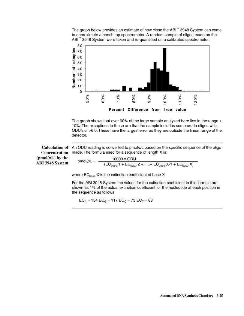
Automated DNA Synthesis Chemistry 3-25
The graph below provides an estimate of how close the ABI™ 3948 System can come to approximate a bench top spectrometer. A random sample of oligos made on the ABI™ 3948 System were taken and re-quantified on a calibrated spectrometer.
The graph shows that over 90% of the large sample analyzed here lies in the range ± 10%. The exceptions to these are that the sample includes some crude oligos with ODU’s of >6.0. These have the largest error as they are outside the linear range of the detector.
Calculation ofConcentration
(pmol/µL) by theABI 3948 System
An ODU reading is converted to pmol/µL based on the specific sequence of the oligo made. The formula used for a sequence of length X is:
where ECbase X is the extinction coefficient of base X
For the ABI 3948 System the values for the extinction coefficient in this formula are shown as 1% of the actual extinction coefficient for the nucleotide at each position in the sequence as follows:
ECA = 154 ECG = 117 ECC = 73 ECT = 88
0
1 0
2 0
3 0
4 0
5 0
6 0
7 0
8 0
50
%
60
%
70
%
80
%
90
%
10
0%
11
0%
12
0%
Percent Difference from true value
Nu
mb
er
of
sa
mp
les
0
10000 x ODU(ECbase 1 + ECbase 2 +......+ ECbase X-1 + ECbase X)
pmol/µL =
3-26 Automated DNA Synthesis Chemistry
Handling ofExtinction
Coefficients inDifferent Software
The instrument handles extinction coefficients differently in different software, as listed in the following table:
ExtinctionCoefficients for
Fluorescent DyeLabels
The relevant extinction coefficients for the available Fluorescent dye labels are
� 6-Fam - 18363
� Hex - 28207
� Tet - 14642
As an example, the 20 base sequence 5’ ATC TAC CTT GGC TGT CAT TG 3’ has three As, four Gs, five Cs and eight Ts. The sum of the extinction coefficients is therefore:
3 x ECA + 4 x ECG + 5 x ECC + ECT = 462 + 468 + 365 + 704 = 1999
If the reported ODU for this oligo was 3.1 then the pmol/µL would be:
Software Version Description
2.0 (NPR) Extinction coefficients of bottles 5–8 are taken as an average of the above four values i.e. )
These values are hard-wired into the image and are not editable.
2.20 (Post-NPR) Values for A, G, C and T are hard-wired into the image but bottles 5-8 are operator specified in the Instrument Preference Page to allow for different 5´labels having different extinction coefficients.
(154 + 117 + 73 + 88)
4= 108
31,0001999
= 15.5 pmol/µL

Automated DNA Synthesis Chemistry 3-27
Storage of the Oligonucleotide
Storage for LaterUse
Most applications for synthetic oligonucleotides require less DNA than the typical 0.5 to 4 ODU of purified oligonucleotide that the ABI 3948 System produces. Fortunately, oligonucleotides can be stored easily, with little or no degradation for long periods of time.
Storage Guidelines Use the following guidelines for storage:
Note Except for oligonucleotides in dry storage, keep oligonucleotides cold to minimize degradation and bacterial growth.
When stored by the above means, oligonucleotides are stable for over a year. Avoid storing oligonucleotides in solutions that are mutagenic, oxidizing, or outside the pH range of 3–12.
Guideline Description
Storage refrigerated in solution
It is most convenient to store them refrigerated as a solution, in either a crude or purified state.
Storage frozen in 20% acetonitrile
Purified oligonucleotides may be stored frozen in the 20% acetonitrile solution.
Storage of crudes Oligonucleotides synthesized and collected crude may be stored in the concentrated ammonia solution.
Other liquid storage media
Other storage media include:
� Ethanol
� Acetonitrile
� Triethylammonium acetate (TEAA)
� Ethylenediamine tetraacetic acid (EDTA)
Dry storage Alternatively, oligonucleotides may be stored as a dried pellet in a clean, dry vessel such as a micro-centrifuge tube.

3-28 Automated DNA Synthesis Chemistry
Alternative Chemistries
Other Monomers In addition to synthesis with the standard phosphoramidite monomers, other monomers may be used on the ABI 3948 System synthesizer. These other monomers include:
� Aminolink
� Biotin
� Deoxyinosine
� Phosphalink, and the
� Fluorescent amidites
Note For more information on the monomers and alternate chemistries listed above, visit the Applied Biosystems Nucleic Synthesis web page as described below.
Please note the following qualifications when using other monomers:
� When using Aminolink or Phosphalink, select the “Crude, DMT-Off” post synthesis option in the New Synthesis Order screen.
� When using the fluorescent amidites, use the “Syn-Pure x.xx Dyes” run protocol.
� When usinging Biotin, select the “Syn-Pure x.xx Biotin” run protocol.
Note The “x.xx” presented in the names above represents the version numbers of Dye and Biotin protocols on your instrument, which vary with date of purchase/software release.
Step Action
1 In your web browser, enter www.appliedbiosystems.com/techsupport as the URL and click "Open" or otherwise enable the web connection to the Applied Biosystems Products and Applications web page.
2 In the Products and Applications web page, click the "Nucleic Acid Synthesis" button.
3 In the Nucleic Acid Synthesis web page, connect with the web page for the chemistry reagent or other topic of interest by clicking the appropriate button.

Overview of Software Commands 4-1
Overview of Software Commands 4
In This Chapter
Topics Covered This section provides information on the command menus available from the Menu bar. A general knowledge of these commands is required to operate the ABI 3948 System Control application. In addition, the New Synthesis Order command contains information about the Synthesis Order form.
This chapter contains three sections:
Section See Page
File and Edit Menus 4-2
Synthesizer and Window Menus 4-20
RunFiles, Sample Labeling, Synthesis Order and Multi-Order Files 4-31
4

4-2 Overview of Software Commands
Section 1 – File and Edit Menus
Topics Covered This section describes the commands on the File and Edit menus and covers the following topics:
Topic See page
Overview of File Menu Commands 4-3
Menu Commands 4-3
Command-Key Commands 4-4
New Synthesis Order Command 4-5
Introduction 4-5
Types of Information 4-5
Description of Fields 4-5
Sequence Entry 4-6
Open Command 4-8
Introduction 4-8
Synthesizer Windows 4-8
Synthesis Orders 4-8
RunFiles 4-8
Multi-Order Files 4-9
Open Synthesizer Command 4-10
Dialog Box 4-10
Procedure 4-10
List of Synthesizer Window Views 4-11
Other File Menu Commands 4-13
Send to Synthesizer Command 4-13
Save a Copy In Command 4-13
Send Copy to Synthesizer Command 4-14
Save and Reopen Command 4-14
Import/Export Command 4-15
Export Procedure Icons 4-16
Generate Run File Command 4-16
Overview of Edit Menu Commands 4-17
Read Selection Command 4-17
Find Command 4-18
Find Same Command 4-18
Replace Command 4-18
Replace Same Command 4-19
Use Sounds Command 4-19

Overview of Software Commands 4-3
Overview of File Menu Commands
Menu Commands The File menu contains commands to perform the following tasks:
Command Description
New Synthesizer Order Creates a new Synthesis Order.
Open Opens a saved Synthesis Order or saved Synthesizer database file.
Opens a Run File for label printing.
Opens a text file to produce Multi-order files.
Open Synthesizer Establishes communication with a synthesizer.
Send to Synthesizer Sends all synthesis setup information from a Synthesizer window to a synthesizer.
Save a Copy In Saves a copy of all information from a Synthesizer to a Synthesizer database.
Send Copy toSynthesizer
Sends a database copy of synthesis setup information to a synthesizer.
Close Closes the selected open Synthesizer window, Synthesizer database, or Synthesis Order,
Close All Synth Orders Closes one or more open Synthesis Orders,
Save Saves changes made to a selected Synthesizer window, Synthesizer database, or Synthesis Order (Save).
CAUTION Be aware that using the Save command with a Synthesizer window to which you have made changes downloads those changes to the synthesizer. You may not want to do this. It is preferable to use the Save As command first, do your edits on the copy, and then use the Send Copy to Synthesizer command.
Using Save with a Synthesizer database or Synthesis Order saves the changes to a Macintosh file.
Save As Saves changes made to an active window to a new file, enabling the file to be renamed.
Save & Reopen Used to fill out multiple orders for the same customer.
Import Sequencea
a. This command reads Import Cycle for an Edit Cycle view or Import Procedure for an Edit Procedure view.
Used to import cycles/procedures/sequences created in another application to an open Synthesis Order or Synthesizer window.
Export Sequenceb
b. This command reads Export Cycle for an Edit Cycle view or Export Procedure for an Edit Procedure view.
Used to export cycles/procedures/sequences from an open Synthesis Order or Synthesizer window.
Generate Run File Generates a Run File for the synthesis.
Page Setup These are regular Macintosh® commands and are not described here.
If you need information on using standard Apple commands, see the Macintosh System Software User’s Guide that came with your computer
Quit
File

4-4 Overview of Software Commands
Note If you have logged on to the synthesizer using a Monitor Access password, the only commands available are Open Synthesizer, Close, and Quit.
Command-KeyCommands
As an alternative for the mouse in choosing some commands, you can use the Command-key equivalent that appears next to some commands on the pop-up menu. For example, to choose the Open command, hold down the Command (�) key and press O.
Note If you have logged on to the synthesizer using a Monitor Access password, the only commands available are Open Synthesizer, Close, and Quit.
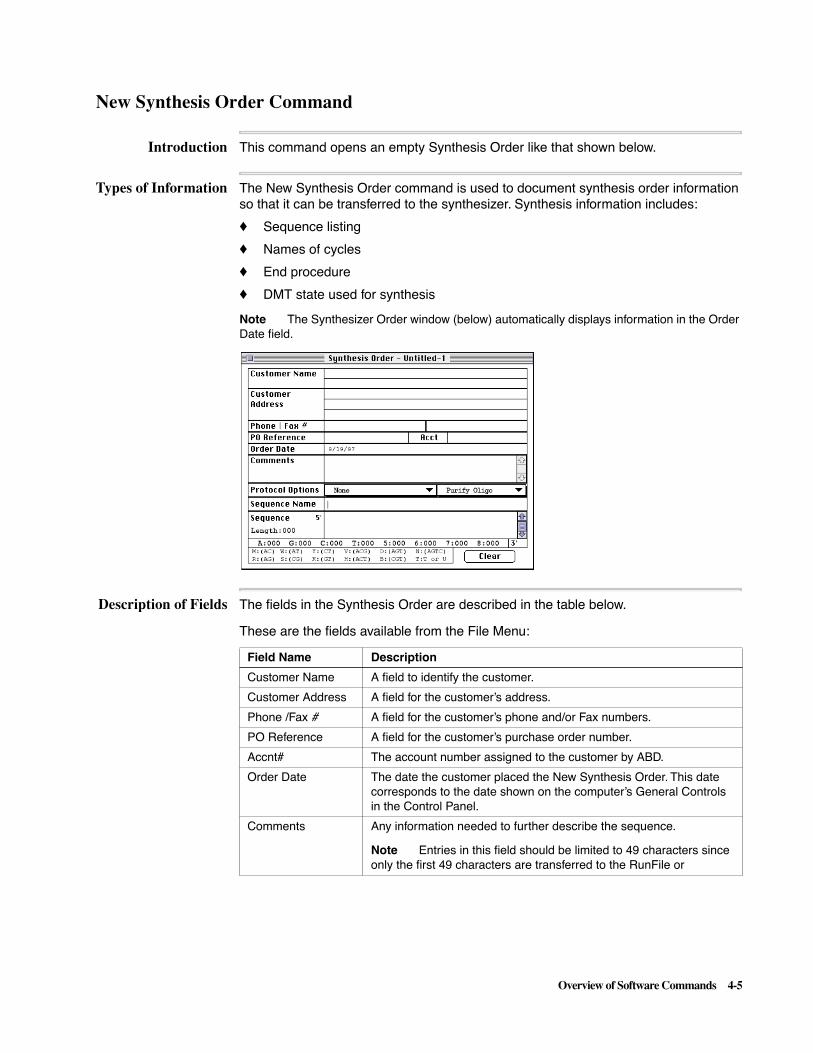
Overview of Software Commands 4-5
New Synthesis Order Command
Introduction This command opens an empty Synthesis Order like that shown below.
Types of Information The New Synthesis Order command is used to document synthesis order information so that it can be transferred to the synthesizer. Synthesis information includes:
� Sequence listing
� Names of cycles
� End procedure
� DMT state used for synthesis
Note The Synthesizer Order window (below) automatically displays information in the Order Date field.
Description of Fields The fields in the Synthesis Order are described in the table below.
These are the fields available from the File Menu:
Field Name Description
Customer Name A field to identify the customer.
Customer Address A field for the customer’s address.
Phone /Fax # A field for the customer’s phone and/or Fax numbers.
PO Reference A field for the customer’s purchase order number.
Accnt# The account number assigned to the customer by ABD.
Order Date The date the customer placed the New Synthesis Order. This date corresponds to the date shown on the computer’s General Controls in the Control Panel.
Comments Any information needed to further describe the sequence.
Note Entries in this field should be limited to 49 characters since only the first 49 characters are transferred to the RunFile or

4-6 Overview of Software Commands
Sequence Entry As you enter a sequence in the Sequence field, the number of A, G, C, T bases are counted in the bottom of the Synthesis Order form and the length of the sequence is listed in the left-hand column. The IUB ambiguity codes are counted as one base for the length of the oligonucleotide.
After you have entered a sequence, you can check your typed entry against a hard copy as follows.
When the Synthesis Order form is completed, you can save the order either as:
� A Synthesis Order (Save and Save As commands), or
� As a sequence file (Export Sequence command)
Synthesis Orders are used both as a record of a customer order and to input the sequence and other information needed for the instrument to produce the oligonucleotide.
Protocol Options Two pull-down menus are available on this line of the Synthesis Order form.
� The first menu allows you to assign any of 15 pre-defined protocols for production of the sequence.
� The second pull-down menu allows the following three choices for the oligonucleotide.
– Purify Oligo - When this choice (the default) is selected, the synthesized oligo is automatically purified.
– Crude - DMT Off - When this choice is selected, the oligonucleotide is not purified and the DMT group at the 5' end of the sequence is automatically removed.
– Crude - DMT On - When this choice is selected, the oligonucleotide is not purified and the DMT group at the 5' end of the sequence is left on.
Sequence Name This field allows you to enter up to 31 characters for the sequence name.
Sequence This field is where you enter the component oligonucleotides in the sequence. Besides the four bases, valid entries include 5, 6, 7, and 8 (bottle positions), and single-character IUB ambiguity codes.
These are the fields available from the File Menu: (continued)
Field Name Description
To check your sequence entry:
Step Action
1 Highlight the entry in the window.
2 Choose the Read Selection command from the Edit menu. A synthesized human voice reads the sequence back to you.

Overview of Software Commands 4-7
Note Be sure to end the sequence on the 3´ end with A, B, C, or T or you will be presented with the message shown in the figure below (synthesis starts at the 3´ end of the sequence and only A, C,G, or T are permissible entries).
When a Synthesis Order is opened in Microsoft Word or other word processors, it contains a complete record of the information entered into the sequence order. When a Synthesis Order is saved as a sequence file and then opened in Word (or other software), it contains only a listing of the sequence.

4-8 Overview of Software Commands
Open Command
Introduction This command opens a directory dialog box (figure below) that displays files created by the ABI 3948 System Control application and stored on the hard disk or on a floppy disk.
The types of files which may be opened by this command include the following:
� Synthesizer Window or database files
� Synthesis Order files
� RunFiles
� Multi-Order text files
SynthesizerWindows
A Synthesizer Window is the window used to control the ABI™ 3948 DNA Synthesis and Purification System. Complete information on the window is provided in Chapter 5 of this manual.
Synthesis Orders Synthesis Orders are the documents loaded into the Synthesizer Window to produce oligonucleotides. Information on this document is presented in several places in the ABI™ 3948 System User and Reference Manuals:
� Information about Synthesis Orders is provided under ““New Synthesis Order Command” on page 4-5 and under “About Synthesis Orders” on page 4-38.
� Information on preparing individual Synthesis Orders is provided under “Preparing Synthesis Orders” on page 4-8 of the ABI™ 3948 System User’s Manual.
� Information on the text files used to create multiple Synthesis Orders is contained in Appendix C of the ABI™ 3948 System User’s Manual.
RunFiles Information on RunFiles is provided in Section 3 of this chapter. Since RunFiles are used as a source for label information, Section 3 also provides the following information to support the process of label generation:
� Detailed information on the contents of RunFiles is provided under “RunFiles” on page 4-32.
� Information on generating labels using the ABI 3948 System Control application is provided under “Sample Labeling Feature” on page 4-33.
� Detailed information on the ABI 3948 System Control window used to generate labels is provided under “Label View Information” on page 4-36.

Overview of Software Commands 4-9
Multi-Order Files Information on Multi-Order files, which are text files used to produce multiple Synthesis Orders, is provided under“Multi-Order Files” on page 4-41 in this section. For detailed information on the syntax of such files, see Appendix C of the ABI™ 3948 System User’s Manual, “Creating and Using Multi-Order Files.”

4-10 Overview of Software Commands
Open Synthesizer Command
Dialog Box Establishes communication with an instrument on either a single zone or multi-zone network. When you choose this command, the Open Synthesizer Dialog box (below) opens.
This dialog box can display a multi-zone network, or list synthesizers on a single zone network.
Note The default application memory setting is 3048K. You can have a maximum of four databases and 48 orders open. If you need to open more windows, you will need to assign more memory to the ABI 3948 System Control application by selecting the application icon (application closed) and using Command-I.
Procedure To establish communication with a synthesizer:
Step Action
1 Choose Open Synthesizer in the File menu.
2 Select the zone name in the scroll box labeled Apple Talk Zones, if applicable.
3 Select a synthesizer in the box labeled Select a Synthesizer.
4 Click OK to present a password dialog box.
5 Enter a password and click OK.
A Synthesizer window like that shown on page 4-11 appears.
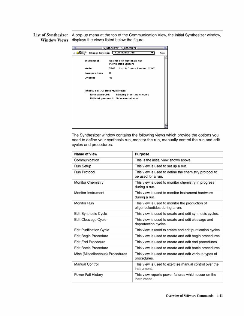
Overview of Software Commands 4-11
List of SynthesizerWindow Views
A pop-up menu at the top of the Communication View, the initial Synthesizer window, displays the views listed below the figure.
The Synthesizer window contains the following views which provide the options you need to define your synthesis run, monitor the run, manually control the run and edit cycles and procedures:
x.xxx
Name of View Purpose
Communication This is the initial view shown above.
Run Setup This view is used to set up a run.
Run Protocol This view is used to define the chemistry protocol to be used for a run.
Monitor Chemistry This view is used to monitor chemistry in progress during a run.
Monitor Instrument This view is used to monitor instrument hardware during a run.
Monitor Run This view is used to monitor the production of oligonucleotides during a run.
Edit Synthesis Cycle This view is used to create and edit synthesis cycles.
Edit Cleavage Cycle This view is used to create and edit cleavage and deprotection cycles.
Edit Purification Cycle This view is used to create and edit purification cycles.
Edit Begin Procedure This view is used to create and edit begin procedures.
Edit End Procedure This view is used to create and edit end procedures
Edit Bottle Procedure This view is used to create and edit bottle procedures.
Misc (Miscellaneous) Procedures This view is used to create and edit various types of procedures.
Manual Control This view is used to exercise manual control over the instrument.
Power Fail History This view reports power failures which occur on the instrument.

4-12 Overview of Software Commands
When you choose one of these views from the pop-up menu, the contents of the Synthesizer window change to display the related options.
Chapters 5 and 6 provide complete descriptions of all the views in the Synthesizer window and the available options.
Instrument Test This view is used to test instrument hardware.
B+Tet Calibration Table This view displays values used to provide maximum times for phosphoramidite deliveries.
Reagent Utilization Table This view is used to calculate the amounts of reagents required during run setup.
Name of View Purpose

Overview of Software Commands 4-13
Other File Menu Commands
Send to SynthesizerCommand
This command sends the contents of the Synthesizer window to a synthesizer. Use the command to send information to the ABI™ 3948 Nucleic Acid Synthesis and Purification System after creating new or modified versions of the following:
� Run Protocols
� Cycles - synthesis, cleavage/deprotection, or purification cycles.
� Begin, End, Bottle, or Shutdown procedures.
� Functions
� Time/Date setting
Note If you have made changes to a Synthesizer window and intend to save them, you should use the Save a Copy In command before using the Send to Synthesizer command, because this is the most direct way of saving your changes.
Save a Copy InCommand
This command makes a complete copy of the run setup, protocols and all other cycles, procedures, and settings for the ABI™ 3948 Nucleic Acid Synthesis and Purification System. It places the information in a computer file, which serves as a backup.
When you choose this command, an alert box like that above informs you that the copying process takes some time.
IMPORTANT The Save a Copy In command copies the contents of the Synthesizer database.
When you click OK to initiate saving a copy, a directory dialog box like that shown below appears.
Assign the file name and location in the directory dialog box.

4-14 Overview of Software Commands
Send Copy toSynthesizerCommand
This command sends a database file that contains all the information in an open database window to the ABI™ 3948 Nucleic Acid Synthesis and Purification System. The database file is created when you choose Save a Copy In... (see page 4-13).
This command is useful for:
� Transferring saved synthesizer information from one instrument to another instrument on the network.
� Restoring all information and instrument settings to a previous backup version. The combination of Save a Copy In and Send Copy to Synthesizer allows many users to share one synthesizer and still have completely individual customized setups.
When you choose this command, a dialog box (see below) displays the ABI™ 3948 instruments that are connected to the computer.
Note For multi-zone networks, the dialog box displays a zone list.
IMPORTANT You will need to recalibrate the sensors only when you reset the database. Sending a copy of a new database does not require a sensor calibration.
Save and ReopenCommand
This command is:
� Useful when filling out a number of Synthesis Orders for the same customer.
� Allows you to enter another sequence without reentering the other information on the form (as you would need to do if you used the New Synthesis Order form).
Note This command is like the Save and Save As commands except that the version of the Order remaining open does not contain any of the sequence information just saved.
Synthesizer-1

Overview of Software Commands 4-15
Import/ExportCommand
The Import and Export commands are available when you are creating a Synthesis Order or creating and editing cycles and procedures in a Synthesizer window. The command name changes to reflect the name of the capability that is currently active, as described in the table below:
Export ProcedureIcons
The Export Procedure command produces a specific type of file. Once exported, you can import a file type into any window that corresponds to the file type. The various file types and corresponding icons are shown in the figure below.
Command Where available
Import Sequence Synthesis Order
Import Cycle Edit Synthesis CycleEdit Cleavage CycleEdit Purification Cycle
Import Procedure Edit Begin ProcedureEdit End ProcedureEdit Bottle ProcedureMisc Procedure
Export Sequence Synthesis Order
Export Cycle Edit Synthesis CycleEdit Cleavage CycleEdit Purification Cycle
Export Procedure Edit Begin ProcedureEdit End ProcedureEdit Bottle ProcedureMisc Procedure
Sequence file or Synthesis Order icon
Cycle file icon
Begin Procedure file icon
End Procedure file icon
Bottle Procedure file icon
Miscellaneous Procedure file icon

4-16 Overview of Software Commands
Generate Run FileCommand
Although a RunFile (see below) is normally generated automatically at the end of a run, you are always prompted by the dialog box shown in the right side of the figure when you click the Load button in the Run Setup view.
The type of RunFile saved by clicking Yes in the dialog box is a TRunFile, the same type produced by the Generate Run File command (the keyboard shortcut for the command is Command - M).

Overview of Software Commands 4-17
Overview of Edit Menu Commands
Overview of EditCommands
The Edit menu commands perform the following tasks:
Besides choosing a command from a menu using the mouse, you can choose a command by using the Command key equivalent that appears on the menu next to the command. For example, choose the Read Selection command by holding down the � key and then pressing K.
Note If you have logged on to the synthesizer using a Monitor Access password, only the Open Synthesizer, Close, and Quit commands are available.
Read SelectionCommand
This command reads aloud the sequence entered into the New Synthesis Order. You can check the entered sequence by comparing the vocalized sequence to the original sequence.
Command Description
Undo Typing/Redo Typing Standard Apple Edit Menu Commands.
Note If you need information about these commands, see the Macintosh System Software Users Guide that came with the computer.
Cut
Copy
Paste
Clear
Read Selection Reads a sequence or portion of a sequence in the Edit Sequence window out loud (Read Selection).
Find/Find Same Find (or find again) a particular sequence of bases in the Edit Sequence view.
Replace/Replace Same Replace (or replace again) a particular sequence of bases in the Edit Sequence view with a designated sequence of bases
Select All Standard Apple Edit Menu Command (see Note above).
Use Sounds Turn on or turn off the sounds that accompany communication between the computer and the 3948 (Use Sounds).
Show Clipboard Standard Apple Edit Menu Command (see Note above).
To hear the sequence read aloud:
Step Action
1 Click the cursor on the sequence.
2 Use the Select All command to highlight the entire sequence, or drag the cursor across the sequence to highlight a portion of the sequence.
3 Choose Read Selection. A synthesized voice reads the order of bases entered in the Sequence field.
4 To interrupt the reading, press the Shift key. The reading stops and unread text remains selected.

4-18 Overview of Software Commands
Find Command This command locates a particular sequence of bases in an Synthesis Order.
Find SameCommand
This command locates the second and subsequent occurrences of the pattern specified by the Find command.
Replace Command This command finds one pattern of bases and replaces it with another.
To find a defined sequence:
Step Action
1 Click the cursor in the sequence.
2 Choose the Find command. A dialog box like that below appears.
3 Enter the pattern you want to find in the dialog box and click Find.
If the pattern is in the sequence, it is highlighted. If the pattern is not found, the computer emits a beep.
Note As a convenience, both Find and Replace ignore differences between lower and upper case letters. You may type everything in lower case. 3948 Control software automatically converts the text to upper case.
To replace one pattern of bases with another:
Step Action
1 Click the cursor in the sequence.
2 Choose the Replace command. A dialog box like that below appears.
3 Enter the pattern you want to remove in the field labeled Find what string?
4 Enter the sequence you want to substitute in the field labeled Replace with what string?
5 Click Replace to change only one occurrence of the base pattern.
Click Replace All to change all occurrences of the base pattern.
Click Find to locate each occurrence of the base pattern.

Overview of Software Commands 4-19
Replace SameCommand
This command repeats the substitution designated in the Replace dialog box (see figure above).
Use SoundsCommand
This command controls the built-in sounds that accompany communication on the network. The command acts like a toggle switch, alternating between the off and on positions.
The sounds verify that communication is occurring (and you may find them entertaining). However, the sounds use computer memory and can slow down communication. Communication is noticeably faster with the sound turned off.

4-20 Overview of Software Commands
Section 2 – Synthesizer and Window Menus
Topics Covered This section describes the commands on the Synthesizer menu, the contents and function of the Instrument Preferences window, and the purpose of the Window menu.
The section covers the following topics:
Topic See Page
Overview of Synthesizer Commands 4-21
Menu Commands 4-21
Abort Command 4-22
Procedure 4-22
Interrupt Command 4-22
Description 4-22
Resume Command 4-22
Description 4-22
Pause After Command 4-23
Introduction 4-23
Programming a Pause 4-23
Synchronize Clocks Command 4-24
Procedure 4-24
Change Password Command 4-25
Procedure 4-25
Change Name Command 4-26
Procedure 4-26
Instrument Preferences Command 4-27
Purpose of the Command 4-27
Auto-Resume Feature 4-27
Setup Variables 4-28
Setup Choices 4-29
Instrument Dip Switches 4-29
Window Menu 4-30
Description 4-30

Overview of Software Commands 4-21
Overview of Synthesizer Commands
Menu Commands The Synthesizer menu provides the commands listed in the table below:
Note These commands are not available if you have logged on to the synthesizer using a Monitor Access password.
Synthesizer Command Description
Abort This command terminates a run in progress.
CAUTION Aborted runs can not be resumed.
Interrupt This command interrupts a run in progress. Use this command when you intend to resume the run.
Note Relay 2 is turned on when a run is Interrupted, is turned off when the run is Resumed, and is pulsed for two-tenths of a second when a run ends. This is done to allow relay 2 to trigger an alarm or other device to alert the operator when a run has paused or ended.
Resume This command resumes an interrupted run.
Pause After This command is used to program a pause during a run. Runs halted with this command are started with the Start button, not the Resume command.
Synchronize Clocks This command is used to synchronize the instrument’s clock with the computer’s clock.
Change Passwords This command is used to change the passwords assigned to the instrument.
Change Name This command is used to change the name assigned to the instrument.
Instrument Preferences This command is important in setting up a run because it opens a special window used to control a number of instrument parameters.

4-22 Overview of Software Commands
Abort Command
Procedure This command stops synthesis immediately. After you use the Abort command, you must completely start over, setting up your run again using the Run Setup window.
The Abort command is used as follows:
Interrupt Command
Description The Interrupt command halts synthesis at the next Safe step and also disables Auto Resume. You can re-start synthesis after an interrupt with the Resume command.
Note A Manual Control action can not be interrupted but procedures can.
Relay 2 is turned on when a run is Interrupted, is turned off when the run is Resumed, and is pulsed for two-tenths of a second when a run ends. This is done to allow relay 2 to trigger an alarm or other device to alert the operator when a run has paused or ended.
Resume Command
Description This command re-starts a run after an interrupt.
Step Action
1 Choose Abort from the Synthesizer pop-up menu while a run is in progress. This will present the following dialog box:
IMPORTANT Be certain that you really want to abort the current synthesis since this command stops all active columns and you must completely start over again.
2 Click Yes if you want to abort the current run or click No if you have reconsidered.

Overview of Software Commands 4-23
Pause After Command
Introduction When you choose the Pause After command (Synthesizer menu) while a run is in progress, a dialog box like this is presented.
The Pause After command enables you to:
� Pause a run after any synthesis listed (and still not completed) in the dialog box.
In the figure example above, only one choice is possible for setting a pause after.
� Set a pause after a number of listed syntheses, if you use the command earlier in the run.
Programming aPause
A Pause After has the following characteristics:
When you are ready to save changes to your pause choices, do the following:
� Click the Save Pause Options button.
� After the system pauses at the programmed point, extend the current run as described in the User’s Manual in “Extending a Run” on page 2-35 of the ABI 3948 User’s Manual.
Characteristic Description
Execution after end of synthesis
A Pause After is executed only after the end of synthesis.
This is necessary because a turntable move is needed to load new columns and the synthesis jaws must remain sealed until synthesis chemistry is completed
Information in dialog box
Besides indicating where a run may be paused, the dialog box provides the following information:
� Syntheses completed (marked by *1)
� Synthesis currently in progress (marked by *4)
� Whether a synthesis is scheduled (marked by *2) or not scheduled (marked by *3).
Set All button The Set All button allows you to set a pause after every available position
Clear All button The Clear All button clears any choices you have made.

4-24 Overview of Software Commands
Synchronize Clocks Command
Procedure This command resets the clock on the ABI™ 3948 instrument to match the clock on the computer. When you choose the command, a dialog box like that below appears.
T
To synchronize the synthesizer and computer clocks:
Step Action
1 Choose the Synchronize Clocks command in the Synthesizer menu.
2 Check the date and time that appears after the word Macintosh.
If it is not correct, click Cancel to close the dialog box. Reset the current date and time on the computer’s Control Panel. See the Macintosh System Software User’s Guide for instructions.
3 When the Macintosh time and date are correct, click OK in the dialog box. The synthesizer’s time and date settings change to match the Macintosh settings.
8
8

Overview of Software Commands 4-25
Change Password Command
Procedure This command is used to assign or change a password.
To assign or change a password:
Step Action
1 Choose the Change Password command from the Synthesizer menu.
This brings up the dialog box to the left below.
2 Do one of the following:
� If no password has been assigned yet, click OK without entering a password.
� Enter the Full Access password if one is assigned.
Either of these actions presents the dialog box shown below:
Note If you enter the wrong password when one has previously been assigned, the dialog box shown to the right in step 1 appears.
3 Do one of the following:
� For Full Access, click the Full Access radio button and then click the Continue button.
� For Monitor Access, click the Monitor Access radio button and then click the Continue button.
Either of these actions will present the dialog box shown to the left below.
4 Re-enter the password you entered in step 2. If you fail to enter the same password, you will be presented with the dialog box shown to the right above.

4-26 Overview of Software Commands
Change Name Command
Procedure This command assigns a name to a synthesizer. The Synthesizer name appears when you choose the Open Synthesizer command to establish communication with the synthesizer, and in the title bar of the Synthesizer window.
When you choose the Change Name command, a dialog box appears like that shown below.
Do the following to change a name:
Step Action
1 Type a synthesizer name in the entry field labeled Name. The entry field holds up to 32 characters.
2 Click OK to finish assigning a name.

Overview of Software Commands 4-27
Instrument Preferences Command
Purpose of theCommand
The command is used to present the Instrument Preferences window, shown below. This window allows a number of chemistry and hardware settings to be made in one place:
The ability to make a number of changes in one place facilitates adjusting the instrument to the specific environmental conditions found in different labs. The Instrument Preferences window also is intended to support the Auto-Resume instrument feature.
Auto-ResumeFeature
The Auto-resume feature, described under “Auto-Resuming” on page 2-17 of the ABI 3948 System User’s Manual, is intended to strike a balance between throughput and reliable operation. See “Auto-Resuming” in the referenced material for more information on using the Auto-resume feature.
Type of Setting Description
Setup Variables
Setup Variables allow the user to change values for key functions in chemistry cycles.
Setup Choices Setup Choices allow a number of choices for hardware or operation conditions.
Instrument Dip Switches
Instrument Dip Switches show the settings of dip switches on the processor (CPU) board and should only be changed by an ABD Service Engineer.
656033380
15200
130
35

4-28 Overview of Software Commands
Setup Variables Entries made for Setup Variables directly change parameter values of a number of key functions in chemistry cycles. This capability allows the user to configure the instrument for different operational conditions. The values shown in the Instrument Preferences example on page 4-27 are the default values and can be changed by selecting the existing entry and typing in a new value.
Note Values entered for Setup Variables in this window are default values: entering a “non-zero” value into the Misc field of the corresponding step of the associated cycle supersedes the Instrument Preferences setting.
Functions affected include:
Function or Parameter Description
Deprotect Temp (170) This variable (for Function 170, “Start Depro Htr”) sets the final temperature at which the deprotection coils are set for deprotection. Final temperature is set here rather than by the associated step in the Cleavage cycle.
Deprotect Mins (169) This variable (for Function 169, “Depro Htr Wait”) sets the minimum time that the deprotection coils will remain hot once the final deprotection temperature has been reached. This time is set here rather than by the associated step in the purification cycle.
Xfer Into Coil (260) This variable (for Function 260, “Set Coil Temp”) sets the temperature at which the deprotection coils are set to for the transfer of the sample from the cleavage vessels into the Deprotection coils. This temperature is set here rather than by the associated step in the purification cycle.
Xfer From Coil (261)/ Coil Cool Secs (261)
These variables (for Function 261, “Wait Coil Temp”) sets the target temperature for the deprotection coil and the time allowed for the temperature to be reached before the transfer from the coils to the purification columns. Temperature and time are set here rather than by the associated step in the purification cycle.
Jaw Leak Test in PSI This variable sets the pressure used for the Jaw/block leak test that is executed when the jaws close after each turntable move at the beginning of each cycle.
Leak OK 0.01 PSI This is the maximum passing leak rate for the Jaw/Block Leak Test in 1/100 of PSI.
Auto-resume Minutes This is the time in minutes that the system waits before auto-resuming from a failed sensor delivery.
Auto-res OK 0.01 PSI This is the maximum jaw leak in 1/100 PSI allowed to keep auto-resume enabled - may not be as large as the Leak OK value.
Ext. Coefficient 5
Ext. Coefficient 6
Ext. Coefficient 7
Ext. Coefficient 8
The values for these parameters represent 1% of the extinction coefficient values for the contents of Bottles 5-8. These values are used to convert ODU values to pmole/mL.
These values can be adjusted to give more accurate quantitation when using bottles 5–8 (default = 10800).

Overview of Software Commands 4-29
Setup Choices These checkboxes provide a central place to make the following hardware or operational settings.
Instrument DipSwitches
These are hand Dip switches on the CPU board whose settings are reflected on this page. They may only be set by taking off a side panel and flipping the switches on the board.
Setup Choice Description
User 4x12 Tube Rack Check this box when you want to use the white rack (4X12 configuration). Leave the box blank to use the red rack (8X6 configuration). This box is unchecked by default.
Pause On Sensor Fail The instrument will pause on a failed sensor delivery with this box checked. The box is checked by default. The system may auto-resume from this pause if auto-resume is enabled.
Pause On Jaw Leak The instrument will pause on a failed leak test with the box checked (unchecked by default). The system will not auto-resume from this pause.
End Row on Jaw Leak The affected turntable row will drop out of the run on a failed jaw leak test but the run will continue processing other rows. This box is checked by default.
Man Cont Jaw Testing This parameter enables jaw/block testing in Manual Control mode. This box is unchecked by default.
Log Dry Sensor Fxns This parameter enables “dry” sensor flows (flushes and backflushes) report to the Microphone log - normally only “wet” sensor deliveries report. Default is unchecked.
Note Be aware that enabling this parameter will produce a much larger Microphone file.
Mnfg. Jaw Test Mode Only used during instrument manufacturing.
Dip Switch Description
Check Illegal Values This parameter is enabled by default. It makes sure no “illegal” value combinations are being attempted (especially by User functions).
No Flow To Open Jaws This box is checked by default since this function is only used to test deliveries to the jaws.
Reserved Reserved for future use.

4-30 Overview of Software Commands
Window Menu
Description The Window menu displays all open Synthesis Orders, Database, Synthesizer, and Print Label windows. When you can select one of the items listed, that window moves to the front of the monitor display and becomes the active window.
Note A Print Label window is a window opened by opening a RunFile window in the ABI™ 3948 System Control application. Information presented for such files includes date of creation (in month, day, year) and time of creation (hour, minute, second, AM or PM). For more information on RunFiles, see “RunFiles” on page 4-32.
Window

Overview of Software Commands 4-31
Section 3 – RunFiles, Sample Labeling, Synthesis Order and Multi-Order Files
Topics Covered This section describes RunFiles, how to use RunFiles to label samples, and Synthesis and Multi-Order files.
The section covers the following topics:
Topic See Page
RunFiles 4-32
Information in the RunFile 4-32
Sample Labeling Feature 4-33
Procedure 4-33
Label View Information 4-36
Introduction 4-36
Information in the Five Columns 4-36
Information in Individual labels 4-36
Label Preferences Button 4-37
About Synthesis Orders 4-38
Introduction 4-38
Ways of Creating Synthesis Orders 4-38
Synthesis Order Sequence Entry 4-39
Importing and Exporting Sequences 4-39
Actions after Sequence Entry 4-40
Multi-Order Files 4-41
Introduction 4-41
Applications Used to Create 4-41
Generating Synthesis Orders 4-43

4-32 Overview of Software Commands
RunFiles
Information in theRunFile
The ABI 3948 System Control application generates a RunFile for each run. Run information is normally automatically generated and stored in a file like that shown below. The information on which a RunFile is based is no longer available from the instrument after the start of the next run.
The following types of information are provided in the RunFile log for each oligonucleotide produced:
� Column position, sequence name and listing for the sequence in each loaded position
� Sample Collector position for labeling the samples
� Begin and End procedure names
� Two measures of the quantity of each oligonucleotide; ODUs (Optical Density Units) and concentration in picomole/µL
� Name of the Synthesis cycle used
� Name of the Cleavage cycle used
� Name of the Purification cycle used
� Date of completion of Synthesis order (date Synthesis order was generated)
Note You can open a RunFile in two ways, by using Simple Text or by using the control application. When opened in Simple Text by double-clicking the File icon (Simple Text must be present on the Macintosh), the RunFile looks like the example in the figure below. Opening the RunFile with the ABI 3948 System Control application allows you to print labels.

Overview of Software Commands 4-33
Sample Labeling Feature
Procedure The ABI 3948 System Control application now has the capability of printing labels for your sample vials. This feature uses the RunFile created by the instrument as the source of the information needed for labeling.
Note If you can’t find a Run file after a run, use the “Generate Run File” command (page 4-16) to generate a new Run file.
To print labels for a run:
Step Action
1 Open the Run file generated by the sample run using the Open command.
A Oligo Labels dialog box like that shown below appears. For an explanation of the information in this view and other views shown in this procedure, see “Label View Information” on page 4-36.
2 To select a different dilution volume, click the Dilution Volumes button to present the Dilute Volumes view:
Note The dialog box shown in the figures in steps 1 and 2 has two views, the Oligo Labels view shown above, and the Dilute Volumes view shown below.

4-34 Overview of Software Commands
3 Scroll the Final Concentration scroll bar (located in the top middle of the Dilute Volumes view) to select the concentration.
You can choose any value in the range of 0.0 to 100 pmol/pmol/µL in 0.5 pmol steps. As you scroll, notice that the amount of reagent needed to dilute each sample changes in the sample listing below.
4 Once the dilution volume is selected, return to the Oligo Labels view by clicking the Oligo Labels button and then scroll to the bottom of the window.
After scrolling, the Oligo Labels view looks like the figure below. This portion of the Oligo Labels view is the Label print area which lists the information to be printed on labels.
5 To see the details of any label in the Label print area, select it to present the contents as shown in the figure above.
Note The contents of the label selected to the upper left are shown in an expanded form at the top of the window. See “Information in Individual Labels” on page 4-36 for a description of label contents.
6 Click the Label Preferences button to present the dialog box shown below.
Note See “Label Preferences Button” on page 4-37 for more information about the contents of this dialog box.
To print labels for a run: (continued)
Step Action

Overview of Software Commands 4-35
Note An alternate way of opening the Oligo Labels dialog box is to drop a RunFile icon onto the icon for the application. This opens the controller application and inputs the selected RunFile.
7 If desired, change the information displayed on each label as follows:
� Change the type of information displayed on the fourth line by clicking the radio button for a new type of information.
� Change the Misc Display Options to enable or disable the display of concentration information:
– Checking the Show pmol values checkbox enables the display of this type of information.
– Checking the “Show odu values” checkbox enables the display of this type of information.
8 Print out a single sheet of labels at the default X- and Y-axis settings to determine if label printing is correctly positioned.
9 Print another sheet of labels to determine if labels print properly:
� If label information is clearly centered and visible, you are done.
� If label information does not print properly, make another setting in step 8 and print out another sheet of labels to check printing.
To print labels for a run: (continued)
Step Action
If the label information... Then...
is clearly centered and visible you are done.
is too far to the left use the upper Printer offset scroll bar to enter a positive X-axis value.
is too far to the right use the upper Printer offset scroll bar to enter a negative X-axis value.
is too far up use the lower Printer offset scroll bar to enter a negative Y-axis value.
is too far down use the lower Printer offset scroll bar to enter a positive Y-axis value.
is not oriented properly check the orientation using the Page Setup command (File menu) and reset it to “Portrait” if necessary.
is too small or too large check the Scale value with the Page Setup command and set it to exactly 100%.

4-36 Overview of Software Commands
Label View Information
Introduction This section provides the following information on the label print views used in the procedure above:
� Information in the Five Columns
� Information in the Individual Labels
� Label Preferences Button.
Information in theFive Columns
The information shown in the five columns of the listing in the Labeling views in steps 1 and 2 above is as follows:
� Column 1 - Sample number
� Column 2 - rack position
� Column 3 - Sample name
� Column 4 - Crude/Purified (when field is blank)
� Column 5 - Dilution volume in µL
Information inIndividual Labels
Notice that the information contained in a selected label is presented at the top of the window. To see the contents of any label in the body of the window, select the label in the portion of the Oligo Labels view shown in step 4.
Note The example in the procedure shows the label contents corresponding to rack position A1 at the top of the window.
These types of information are shown in each label:
� Chemistry protocol name on the top line.
� Rack position (A1, etc., at the start of line two.
� Concentration in pM/µL (picomole/microliter) at the end of line two.
� Date of run at start of line three (011496 = November 4, 1996).
� Concentration in ODUs at the end of line three.
� Line 4 is blank until entry is made using the Label Preference button.

Overview of Software Commands 4-37
Label PreferencesButton
The Label Preferences button presents the Label Preferences dialog box, shown in step 6, which enables you to do the following:
Task Description
Centering label information
Adjust the x- and y-axis offsets for the printer so that label information can be centered on the label.
Specifying contentsof fourth line
Specify the content of the fourth line of the label and adjust the position of printing so that label annotation is correctly centered on the label
Specifying type of information on fourth line
Specify the type of Information presented on the fourth line of each label, which includes:
� Customer name
� PO (Purchase Order) number
� Account number
� A brief comment (it must fit on the fourth line)
Specifying additionalinformation
Specify that pM/µL and ODU information be presented on labels by checking the appropriate checkbox.

4-38 Overview of Software Commands
About Synthesis Orders
Introduction The Synthesis Order is the document used to input sequences into the ABI™ 3948 Synthesis and Purification system. A Synthesis Order documents other details about the run used to produce it such as:
� Customer name
� Address
� Phone or Fax number
� Order date
� PO number
There are three Synthesis Order formats:
� The single order file format
� The short multiple order file format
� The long multiple order file format
The single order file is the type of Synthesis Order created in the Control application by the New Synthesis Order command from the File menu. The two multiple order formats are alternative ways to generate single order files. Text files using the short or long multiple order file formats are called Multi-order files.
Ways of CreatingSynthesis Orders
The most direct way of creating a Synthesis Order is to use the New Synthesis Order command from the File menu of the ABI 3948 System Control application. This creates orders one at a time with a separate Synthesis Order required for each oligonucleotide synthesized.
An example of a Synthesis Order is shown below. The Synthesis Order is described in detail under “Types of Information” on page 4-5.
The Multi-order file capability was added to the ABI 3948 instrument application to expedite creation of multiple Synthesis Orders as follows:
� Creating Multi-order files is a two-step process which requires you to create a text file in the proper format, either the short or long format, and then open the files in the ABI 3948 instrument application.

Overview of Software Commands 4-39
� After the ABI 3948 System application opens a Multi-order file, the application is used to generate “single” Synthesis Order files for input to the instrument. An example of an opened Multi-order long format file is shown below.
Note For a detailed description of Multi-order file formats and how to use the Multiple Order window, see Appendix C of the ABI™ System 3948 User’s Manual, “Creating and Using Multi-Order Files.” Synthesis Orders, however created, appear like the example shown in the figure on “Ways of Creating Synthesis Orders” on page 4-38.
Once single format Synthesis Orders are created, they can be sent to the Synthesis database during run setup and then downloaded to the instrument when the run starts. For more information on this, see the instructions provided in Chapter 2 of the ABI™ 3948 System User’s Manual (“Assigning Sequences for the Run” on page 2-22).
Synthesis OrderSequence Entry
When you directly create a single order file using the New Synthesis Order command, a sequence can be input into the order in one of three ways:
� By typing it in
� By importing a sequence from a file using the Import Sequence command, or
� By using cut and paste to transfer the sequence from other applications
Once you have input a sequence, you can use it as is or you can edit it.
Note One type of edit is to change the A, G, C, and T letter representation to bottle position representation (5, 6, 7, 8).
Besides entry of the sequence in terms of the four bases, sequences can be entered or imported using mixed bases as a designation for a base site or ambiguity characters can be used to designate a base site.
Importing andExportingSequences
Upon opening a new Synthesis Order, the Import Sequence command (File menu) is available to import sequences. This command, however, can only be used to import sequences previously exported to a file to be archived from the ABI 3948 System Control application.
Once you have completed a Synthesis Order, the Export Sequence command is available to write a plain text file containing only the sequence for use as input to all programs that accept plain text input.
IMPORTANT The Export Sequence command is probably not the best way of maintaining a library of sequences since it provides just the sequence text.

4-40 Overview of Software Commands
Rather than exporting a sequence, it is better to use a Synthesis Order file to store each sequence since you are provided with fields for:
� Customer information
– Name
– Address
– Phone and Fax number
� Purchase Order and Account information
� Order Date
� Comments
� Protocol Option
� Sequence name
� Numbers of each of the bases or bottle positions 5 through 8
Synthesis Orders can be opened as well in many other applications.
Actions afterSequence Entry
Once you have created or edited a sequence, you can:
� Highlight the sequence listing and read it back using the Read Selection command (Edit menu) to ensure that it was entered correctly.
� Save the Synthesis Order containing the sequence for use in producing an oligonucleotide in the instrument
� Print out a copy, or
� Export the sequence to a file to be archived

Overview of Software Commands 4-41
Multi-Order Files
Introduction Multi-order (multiple Synthesis Order) files are discussed in this chapter because they may be opened by the Open command. Only general information is provided here. For a detailed description of the use of Multi-order files, see Appendix C of the ABI™ 3948 User’s Manual, “Creating and Using Multi-Order Files.?
Multi-order text files are created in either of two formats by a text processor and have the following characteristics:
Types ofApplications Used to
Create
All Multiple Order files may be generated any of the following types of applications:
� A text editor or a word processor that has its formatting capabilities disabled
� A stand-alone application such as a Web page order entry program
� A spreadsheet or database management program, especially one with programming or scripting capabilities
Multiple Synthesis Order files appear as shown below when opened with the ABI 3948 System Control application Open command:
Characteristic Description
Correct syntaxand starting tag
Multi-order files must have the correct syntax and start with a SYNTHMOSFORMAT tag for the short format or a SYNTHMOLFORMAT tag for the long format.
Limitation of short format
The short format only provides the capability to name the resulting oligonucleotide and list the sequence.
Additional long format capabilities
The long format additionally provides the capability to:
� List the names of the customer and synthesizer.
� Add comments.
� Set the DMT and PUR options.
Maximum number of Synthesis Orders
The maximum number of Synthesis Orders which can be created with a single Multiple Order file is 999.

4-42 Overview of Software Commands
Note Both Long and Short Format files appear as shown in the figure but the Long Format file will create Synthesis Orders with more content when additional entries are made in the text file.
GeneratingSynthesis Orders
Once a Multiple Order file is created, in either format, all that is required to generate single order Synthesis files is to open the file from the ABI 3948 System Controller application and then click the Make Order Files button (see figure on previous page).

Communication View and Operational Views 5-1
Communication View and Operational Views 5
In This Chapter
Topics Covered This section provides detailed information on a number of Synthesizer views used to operate the instrument from the ABI™ 3948 System Control application. The pop-up menu in all views is used to access any other Synthesizer view.
This chapter contains two sections:
Topic See page
General Information about Operational Synthesizer Views 5-2
Using the Run SetUp View 5-20
5
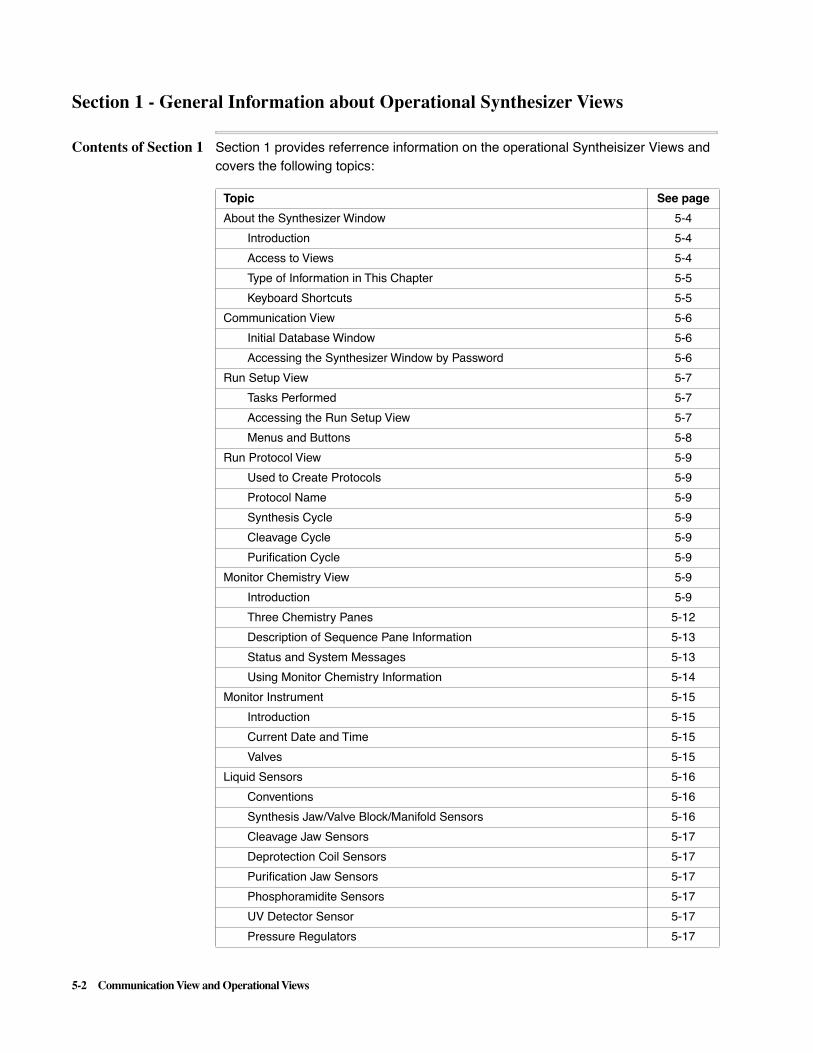
5-2 Communication View and Operational Views
Section 1 - General Information about Operational Synthesizer Views
Contents of Section 1 Section 1 provides referrence information on the operational Syntheisizer Views and covers the following topics:
Topic See page
About the Synthesizer Window 5-4
Introduction 5-4
Access to Views 5-4
Type of Information in This Chapter 5-5
Keyboard Shortcuts 5-5
Communication View 5-6
Initial Database Window 5-6
Accessing the Synthesizer Window by Password 5-6
Run Setup View 5-7
Tasks Performed 5-7
Accessing the Run Setup View 5-7
Menus and Buttons 5-8
Run Protocol View 5-9
Used to Create Protocols 5-9
Protocol Name 5-9
Synthesis Cycle 5-9
Cleavage Cycle 5-9
Purification Cycle 5-9
Monitor Chemistry View 5-9
Introduction 5-9
Three Chemistry Panes 5-12
Description of Sequence Pane Information 5-13
Status and System Messages 5-13
Using Monitor Chemistry Information 5-14
Monitor Instrument 5-15
Introduction 5-15
Current Date and Time 5-15
Valves 5-15
Liquid Sensors 5-16
Conventions 5-16
Synthesis Jaw/Valve Block/Manifold Sensors 5-16
Cleavage Jaw Sensors 5-17
Deprotection Coil Sensors 5-17
Purification Jaw Sensors 5-17
Phosphoramidite Sensors 5-17
UV Detector Sensor 5-17
Pressure Regulators 5-17

Communication View and Operational Views 5-3
Other Parameters and Instrument Conditions 5-18
Monitor Run View 5-19
Introduction 5-19
Types of Information Provided 5-19
Topic See page

5-4 Communication View and Operational Views
About the Synthesizer Window
Introduction The Synthesizer window of the ABI 3948 System Control application:
� Appears on the computer monitor whenever you establish communication between the computer and a ABI 3948 System.
Note Up to four instruments at a time may be used with a single Macintosh.
� Contains all the tools you need to control and monitor the ABI™ 3948 Nucleic Acid Synthesis and Purification System.
The initial Synthesizer window, shown below, is the Communication view. This view appears whenever the ABI 3948 System Control application accesses an instrument.
Access to Views A pop-up menu at the top of the Synthesizer window displays the following views:
2.20x.xx
Pop-up menu
List of Synthesizer Window views:
View Purpose
Communication Initial view listing software version
Run Setup Used to set up a run
Run Protocol Used to create new protocols
Monitor Chemistry Used to monitor chemistry during a run
Monitor Instrument Used to monitor instrument hardware during a run
Monitor Run Used to monitor the Synthesis Orders produced during a run
Edit Synthesis Cycle Used to create and edit Synthesis cycles
Edit Cleavage Cycle Used to create and edit Cleavage and Deprotection cycles
Edit Purification Cycle Used to create and edit Purification cycles
Edit Begin Procedure Used to create and edit Begin procedures
Edit End Procedure Used to create and edit End Procedures
Edit Bottle Procedure Used to create and edit Bottle Procedures
Misc (miscellaneous) Procedure
Used to create and edit other types of procedures
Manual Control Used to manually execute functions

Communication View and Operational Views 5-5
Type of Informationin This Chapter
To avoid presenting information in the same way in both the User and Reference manuals, Chapter 2 of the ABI™ User manual provides procedural information for the Synthesizer window and this chapter of the ABI™ Reference manual may provide procedures but primarily provides user interface details.
Keyboard Shortcuts As an alternative to the pop-up menu in the Synthesizer Window, you can simultaneously press the Command key (�) and one other key on the computer keyboard to see nine of the views.
Power Fail History Provides a listing of instrument power failures
Instrument Test Used to test instrument hardware
B+Tet Calibration Table Lists maximum times for B+Tet deliveries
Reagent Utilization Table Lists volumes for various reagent deliveries
List of Synthesizer Window views: (continued)
View Purpose
Synthesizer Window View Keyboard Shortcut
Run Setup c 1
Run Protocol c 2
Monitor Chemistry c 3
Monitor Instrument c 4
Edit Synthesis Cycle c 5
Edit Cleavage Cycle c 6
Edit Purification Cycle c 7
Edit Bottle Procedure c 8
Manual Control c 9

5-6 Communication View and Operational Views
Communication View
Initial DatabaseWindow
The initial instrument database window which appears is the Communication view.
The Communication view of the Synthesizer window appears when you choose an instrument and a password dialog box is presented as the window appears.
Two types of passwords provide access to the Synthesizer window:
� Full Access - provides access to all views of the window
� Monitor Access - provides access only to the Monitor Chemistry, Monitor Instrument, Monitor Run, and Power Fail History Views.
Accessing theSynthesizer Window
by Password
Open up a Synthesizer window as follows:
2.20x.xx
Step Action
1 Choose the Open Synthesizer command and select the instrument to be opened from the dialog box. This will present the Communication view and a Password dialog box like that shown to the left below:
2 Type in the password in the dialog box and click OK to open access to the Synthesizer database:
� If no password has yet been assigned, click OK without entering a password.
� If an incorrect password is entered, the dialog box shown to the right below replaces the first dialog box. Clicking OK in this dialog box presents the dialog b ox to the left again.
Note You must enter the correct password to get past this point.

Communication View and Operational Views 5-7
Run Setup View
Tasks Performed This subsection provides general interface information on the first page on the Run Setup View. For information on other Run Setup view windows, see Section 2 of this chapter.
The Run Setup view, shown below, enables you to perform the following tasks:
Accessing the RunSetup View
The Run Setup view is chosen either by executing this command from the Communications view menu or by the Command - 1 key sequence.
Task Description
Select sequencesfor the next run
Select/remove sequences to be used for the next run.
Assign chemistry and sort sequences
Assign chemistry protocols and sort the sequences by protocol to determine turntable loading positions.
Determine if sufficient reagents are on instrument
Determine if additional reagents are needed for the next run.
When insufficient reagents are available for the entire run, the options are:
� To replace reagents before the run
� To program a Pause After to replace reagents
Install OneStep columns
Place OneStep columns in the proper positions on the turntable to prepare for the run.
Prepare for run extension
Program a “Pause After” during a run to occur after synthesis has completed on a designated turntable row in preparation for run extension
Perform setup needed to extend a run
Enter sequences and load columns needed for run extension during a programmed system pause and then restart the run.

5-8 Communication View and Operational Views
Menus and Buttons Various details of the Run Setup view are described in the following table:
Run Setup View Pop-Up Menus and Buttons
Pop-up Menus and Buttons Descriptions
Open This button is used to input Synthesis Orders into the Sequence Order list.
Del From List After you have moved sequences into the Sequence Order list using the Open button, the Del From List button is used to remove any selected sequence from this list.
Add+ Click the Add + button to transfer one or more selected sequences from the Sequence Order List to the Run Setup list.
Remove Click the Remove button to transfer a selected sequence from the Run Setup Order box back to the Sequence Order List.
Protocol Pop-up menu This pop-up menu allows a protocol to be assigned to a selected row in the Run Setup list.
AutoSort This button is used to autosort the sequences entered into the Run Setup list to maximize throughput on the instrument. See "AutoSort Procedure" on page 2-24 of the ABI™ 3948 System User’s manual for more information
Begin and End Procedure Pop-up Menus
These menus allow a different Begin and End procedure to be assigned in this view, but only if you have previously developed them.
Bottle Usage This button presents the Bottle Usage window to determine if sufficient reagents are present on the instrument to accommodate the current run. See "Checking Reagents and Required OneStep Columns" on page 2-27 of the ABI™ 3948 System User’s manual for more information.
The Bottle Usage window also indicates how many of each type of OneStep column is required.
Load This button presents the Load window enabling OneStep columns to be properly placed on the instrument. See "Loading" on page 2-30 of the ABI™ 3948 System User’s manual for more information.
Extend Run This button is used to extend a run when the run has been interrupted by a programmed “Pause After.” See "Using “Pause After” During a Run" on page 2-35 of the ABI™ 3948 System User’s manual for more information.

Communication View and Operational Views 5-9
Run Protocol View
Used to CreateProtocols
The Run Protocol view is used to create protocols from the available cycles and procedures. This view initially looks like the figure below:
Each protocol comprises: a Synthesis Cycle, a Cleavage Cycle, and a Purification Cycle. Use the Run Protocol view as follows:
� When you select a protocol from the Protocol Name pop-up menu, its component cycles and procedures appear.
� If you select an undefined protocol, its component cycles and procedures become the default values listed for the standard protocol.
� To create a new protocol, enter a new name for the protocol, then choose the cycles and procedures from each pop-up menu, and click the Change button.
Note The Edit Synthesis Cycle, Edit Cleavage Cycle, and Edit Purification Cycle views are available to develop new cycle chemistry.
Protocol Name This pop-up menu lists the standard protocols (standard, dye-labeled, and biotin) and the additional undefined protocols.
Synthesis Cycle This pop-up menu lists standard Synthesis Cycles and additional undefined cycles. Use the Edit Synthesis Cycle view to define a new Synthesis Cycle or edit an existing one (see page 6-17).
Cleavage Cycle This pop-up menu lists standard cycles and additional undefined cycles. Use the Edit Cleavage Cycle view to define a new Cleavage Cycle or edit an existing one (see page 6-18).

5-10 Communication View and Operational Views
Purification Cycle This pop-up menu lists standard cycles and additional undefined cycles. Use the Edit Purification Cycle view to define a new Purification Cycle or edit an existing one (see page 6-19).

Communication View and Operational Views 5-11
Monitor Chemistry View
Introduction The Monitor Chemistry view, shown below, has the following four main areas:
Note This is the only view that will not display a “Message Waiting” or “Critical Message Waiting” icon to the upper left because all messages are presented at the bottom of this view.
The following conventions apply to interpreting the Monitor Chemistry View:
Area Description
Upper right corner
A system status indicator in the upper right corner.
Three Chemistry panes
Three Chemistry panes (Synthesis, Clv/Dep, Dep/Pur) occupying about one half of the window which present information about the chemistries in progress.
Small middle pane
A small middle pane which provides information about the sequences currently undergoing synthesis on the Synthesis pane.
Lower pane A lower pane which presents a series of messages from the instrument.
Convention Description
Grouping of three As shown in the figure above, the turntable position numbers are placed in the three panes in groups of three
Each group is a row Each group of three represents a radial row of column positions on the turntable which undergo the same type of chemistry.
Same cycle on each group
The instrument uses the same cycle on each group of three oligonucleotides and concurrently uses three different cycles at the processing stations.
Syn v4.20f Cleave v4.20g
, DB 4.20, 2.20.
, DB 4.20, 2.20.
C
5-12 Communication View and Operational Views
The general status of the instrument is indicated in all views by presentation of one of the following four words in the upper right corner:
� Ready
� Running
� Manual Control
� Interrupted.
Three ChemistryPanes
The three chemistry panes (Synthesis, Clv/Dep, Dep/Pur) show details of the chemistries in progress in the three chemistry modules. After the first set of three columns reaches the Purification module, three chemistries are concurrently in progress on the instrument (until the end of the run).
Progress of Chemistry
Chemistry progresses as follows when a run is started:
Description of Chemistry Panes
All three panes show the same types of information, described in the two tables below:
Stage Action
1 First the Begin procedure can be seen executing in the left pane.
2 Next, when the first three columns are undergoing synthesis, only this type of chemistry is in progress and information is presented only in the left pane.
3 When the first three columns move to the Cleavage module, the next set of three oligonucleotides starts synthesis. Synthesis and Cleavage chemistries are concurrently in progress at this point.
4 Finally, when the first set of three columns reaches the Purification module, all three chemistries are concurrently in progress with all three panes showing chemistry details.
Location Purpose
Upper Part of Pane
This portion of each pane shows two types of information:
� The turntable position of each oligonucleotide, expressed as a number between 1 and 48, and
� The name of each sequence (Synthesis Order name; the name of the sequence may be different than the Synthesis Order name).
Note If no name is specified when making a Synthesis Order, the default name is the sequence name when one is entered.
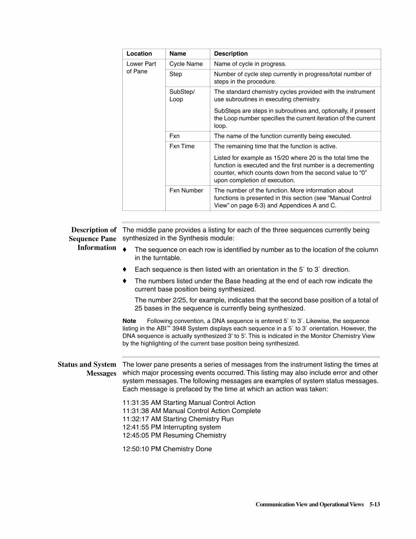
Communication View and Operational Views 5-13
Description ofSequence Pane
Information
The middle pane provides a listing for each of the three sequences currently being synthesized in the Synthesis module:
� The sequence on each row is identified by number as to the location of the column in the turntable.
� Each sequence is then listed with an orientation in the 5´ to 3´ direction.
� The numbers listed under the Base heading at the end of each row indicate the current base position being synthesized.
The number 2/25, for example, indicates that the second base position of a total of 25 bases in the sequence is currently being synthesized.
Note Following convention, a DNA sequence is entered 5´ to 3´. Likewise, the sequence listing in the ABI™ 3948 System displays each sequence in a 5´ to 3´ orientation. However, the DNA sequence is actually synthesized 3' to 5'. This is indicated in the Monitor Chemistry View by the highlighting of the current base position being synthesized.
Status and SystemMessages
The lower pane presents a series of messages from the instrument listing the times at which major processing events occurred. This listing may also include error and other system messages. The following messages are examples of system status messages. Each message is prefaced by the time at which an action was taken:
11:31:35 AM Starting Manual Control Action11:31:38 AM Manual Control Action Complete11:32:17 AM Starting Chemistry Run12:41:55 PM Interrupting system12:45:05 PM Resuming Chemistry
12:50:10 PM Chemistry Done
Location Name Description
Lower Part of Pane
Cycle Name Name of cycle in progress.
Step Number of cycle step currently in progress/total number of steps in the procedure.
SubStep/Loop
The standard chemistry cycles provided with the instrument use subroutines in executing chemistry.
SubSteps are steps in subroutines and, optionally, if present the Loop number specifies the current iteration of the current loop.
Fxn The name of the function currently being executed.
Fxn Time The remaining time that the function is active.
Listed for example as 15/20 where 20 is the total time the function is executed and the first number is a decrementing counter, which counts down from the second value to “0” upon completion of execution.
Fxn Number The number of the function. More information about functions is presented in this section (see “Manual Control View” on page 6-3) and Appendices A and C.

5-14 Communication View and Operational Views
The log on the bottom of this view informs you of the following types of events:
� When an instrument run was interrupted or aborted
� When a sensor fails to detect liquid (which may or may not interrupt the run)
� Instructions used during procedures (such as autodilution)
� Power fail information
� Start and stop times of chemistry runs
� Execution of runs or manual control events
The information presented on this log is intended to inform a user about the normal progress of a run and for troubleshooting. For a full list of messages presented in the log, see "System Messages" on page C-38 of Appendix C
Using MonitorChemistry
Information
While information in the Monitor Chemistry view is primarily used to keep track of chemistry in progress, the log on the bottom also informs you when an interrupt or Pause After occurs so that you can perform a bottle change procedure, remove a high priority oligonucleotide, or extend the run.
Instructions to the user during procedures (calibration, bottle change, etc.) are presented in the log. You can also use the log for troubleshooting the instrument in conjunction with the Monitor Instrument view.

Communication View and Operational Views 5-15
Monitor Instrument
Introduction The Monitor Instrument view, shown with a run in progress in the figure below, displays the status of system valves, liquid sensors, pressure regulators, as well as other parameters and instrument conditions. These parameters and conditions include
� Chemistry status
� Deprotection coil temperature
� Current turntable and sample collector positions
� Status of Synthesizer, Cleavage, and Purification jaws, and
� Status of heater and fan
This view is best used in conjunction with the Monitor Chemistry view to troubleshoot problems which may occur at any point during a particular chemistry.
Current Date andTime
The current ABI™ 3948 System date and time is displayed at the top of the window, to enable you to correlate particular events occurring in one of the chemistry cycles with the underlying hardware and/or software supporting chemistry.
Valves The Monitor Instrument view supports up to 80 numbered valves in its current form. The status of valves is indicated in groups of five symbols, 10 valves per line, with the status of a particular valve marked with either a bullet or an exclamation point:
� Valves that are off are indicated by a bullet, and
� Valves that are on are indicated by an exclamation point
Separating each line of 10 valves into two groups of five makes the display easier to read.

5-16 Communication View and Operational Views
Liquid Sensors
Conventions The instrument has a number of liquid sensors placed in critical portions of its plumbing to ensure that liquid transfers are being made. See "Edit Cycle and Procedure Interface" on page 6-12 for information on enabling a sensor for a particular function.
When enabled in the cycle or procedure, a check in a liquid sensor check box indicates that liquid is detected at the current time at the sensor. In the discussion in this section, sensors are grouped according to:
� The position in the plumbing, or
� The type of phosphoramidite monitored
Except for the check boxes labeled A, G, C, and T, which indicate phosphoramidites, all of the letters A,B, and C included as part of a sensor designation indicate one of the three positions in a jaw mechanism:
You can locate the sensors by number on the instrument plumbing diagram provided in Appendix D. A checked box for a particular sensor means that liquid is present at the sensor at the current time. An unchecked box means that gas is present at the sensor at the current time.
Synthesis Jaw/ValveBlock/Manifold
Sensors
The synthesis sensors listed in the table below are in the plumbing on either the upper or lower side of the synthesis jaw mechanism:
� The first three sensors are located on the upper side of the jaw mechanism.
� The next three sensors, labeled “Man.”, are located just below the first manifold under the synthesis jaw.
� The last three sensors, labeled “Syn. Lower,” are located closest to the reagent delivery valve blocks.
Position Description
Position A Position A corresponds to the outer in a row of columns in the turntable.
Position B Position B is the middle position.
Position C Position C is the inner position.
Name Identity Purpose
SUA Syn. Upper A - Sen. 3 Determines that reagent for the listed position has reached the sensor position.SUB Syn. Upper B - Sen. 2
SUC Syn. Upper C - Sen. 1
ManA Man. A - Sen. 22 Determines that reagent for the listed position reaches the sensor position.ManB Man. B - Sen. 23
ManC Man. C - Sen. 24
SLA Syn. Lower A - Sen. 6 Determines that reagent for the listed position reaches the sensor position.SLB Syn. Lower B - Sen. 5
SLC Syn. Lower C - Sen. 4

Communication View and Operational Views 5-17
Cleavage JawSensors
The three sensors listed in the table below are in the plumbing on the upper side of the cleavage jaw mechanism:
Deprotection CoilSensors
The three sensors listed in the table below are in the plumbing on the exit side of the deprotection coils:
Purification JawSensors
The three sensors listed below are in the plumbing on the upper side of the purification jaw mechanism:
PhosphoramiditeSensors
The four sensors listed below are in the plumbing between the phosphoramidite bottles and Valve Block B:
UV Detector Sensor A single sensor, labeled UVQ, is in the plumbing input to the UV detector.
Pressure Regulators The current values in psi (pounds per square inch) for the ten pressure regulators are shown in this portion of the Monitor Instrument view:
� The ten pressure regulators initially have the values listed in the table.
� Except for Regulators 1, 3 and 10, the regulators are maintained within ±0.2 psi of the initial pressures.
Name Identity Purpose
CA Cleavage A - Sen. 7 Determines that reagent for the listed position has reached the sensor position.CB Cleavage B - Sen. 8
CC Cleavage C - Sen. 9
Name Identity Purpose
DEPA Coil A - Sen. 10 Determines that reagent for the listed position has reached the sensor position.DEPB Coil B - Sen. 11
DEPC Coil C - Sen. 12
Name Identity Purpose
PA Pur. A - Sen. 14 Determines that reagent for the listed position has reached the sensor position.PB Pur. B - Sen. 15
PC Pur. C - Sen. 16
Name Identity Purpose
A Phos. A - Sen. 17 Determines that reagent for the listed position has reached the sensor position.G Phos. G - Sen. 18
C Phos. C - Sen. 19
T Phos. T - Sen. 20
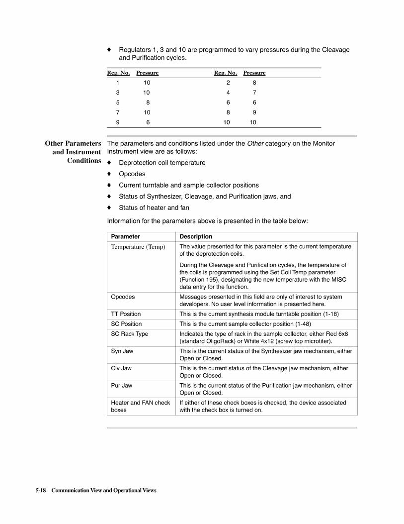
5-18 Communication View and Operational Views
� Regulators 1, 3 and 10 are programmed to vary pressures during the Cleavage and Purification cycles.
Other Parametersand Instrument
Conditions
The parameters and conditions listed under the Other category on the Monitor Instrument view are as follows:
� Deprotection coil temperature
� Opcodes
� Current turntable and sample collector positions
� Status of Synthesizer, Cleavage, and Purification jaws, and
� Status of heater and fan
Information for the parameters above is presented in the table below:
Reg. No. Pressure Reg. No. Pressure
1 10 2 8
3 10 4 7
5 8 6 6
7 10 8 9
9 6 10 10
Parameter Description
Temperature (Temp) The value presented for this parameter is the current temperature of the deprotection coils.
During the Cleavage and Purification cycles, the temperature of the coils is programmed using the Set Coil Temp parameter (Function 195), designating the new temperature with the MISC data entry for the function.
Opcodes Messages presented in this field are only of interest to system developers. No user level information is presented here.
TT Position This is the current synthesis module turntable position (1-18)
SC Position This is the current sample collector position (1-48)
SC Rack Type Indicates the type of rack in the sample collector, either Red 6x8 (standard OligoRack) or White 4x12 (screw top microtiter).
Syn Jaw This is the current status of the Synthesizer jaw mechanism, either Open or Closed.
Clv Jaw This is the current status of the Cleavage jaw mechanism, either Open or Closed.
Pur Jaw This is the current status of the Purification jaw mechanism, either Open or Closed.
Heater and FAN check boxes
If either of these check boxes is checked, the device associated with the check box is turned on.

Communication View and Operational Views 5-19
Monitor Run View
Introduction The Monitor Run view, shown in the figure below, is another way of observing the progress of an ABI™ 3948 System run. Information in this view is useful in tracking the general course of chemistry, knowing when to set a Pause After in the run, and is a table of the entire run which provides useful information in tracking the run.
Types of InformationProvided
The Monitor Run view provides the following types of information about the run in the form of a table:
Type of Information Description
Row Each of the 16 rows in the turntable is labeled by number in the first column.
Column A Names of the three Synthesis Orders on each row of the turntable are listed row by row in second through fourth columns of the table.Column B
Column C
Chemistry Status The fifth column lists the current chemistry status for each row – a particular row has one of these notations:
� 1) Scheduled/Not scheduled
� 2) Synthesizing
� 3) Cleaving
� 4) Purifying
� 5) Completed
Pause After The sixth column, Pause After, has either “No”, “Yes”, or nothing after a row to indicate whether a pause has been programmed.

5-20 Communication View and Operational Views
Section 2 - Using the Run Setup View and Extending a Run
Contents of Section 2 This section describes how to use the Run Setup view and extend a run.
The section covers the following topics:
Topic See page
Importing Synthesis Orders 5-21
Process of Importing Synthesis Orders 5-21
Description of Open Dialog Box Buttons 5-22
Selecting Orders for the Next Run 5-23
Description 5-23
Synthesis Order Information Provided for a Selected Sequence 5-24
Provided for a Selected Sequence 5-24
Assigning Chemistry and AutoSorting 5-25
Introduction 5-25
Assigning Chemistry 5-25
AutoSorting 5-25
Bottle Usage 5-27
Procedure 5-27
Using the Load Display 5-28
Types of Information Provided 5-28
Procedure for the Load Display 5-28
Significance of the Three Positions 5-28
Protocol and Cycle Identification 5-29
Using the Buttons on the Display 5-29
Extending a Run 5-30
Using Pause After 5-30
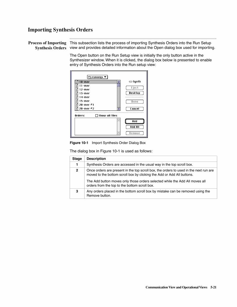
Communication View and Operational Views 5-21
Importing Synthesis Orders
Process of ImportingSynthesis Orders
This subsection lists the process of importing Synthesis Orders into the Run Setup view and provides detailed information about the Open dialog box used for importing.
The Open button on the Run Setup view is initially the only button active in the Synthesizer window. When it is clicked, the dialog box below is presented to enable entry of Synthesis Orders into the Run setup view:
Figure 10-1 Import Synthesis Order Dialog Box
The dialog box in Figure 10-1 is used as follows:
Stage Description
1 Synthesis Orders are accessed in the usual way in the top scroll box.
2 Once orders are present in the top scroll box, the orders to used in the next run are moved to the bottom scroll box by clicking the Add or Add All buttons.
The Add button moves only those orders selected while the Add All moves all orders from the top to the bottom scroll box.
3 Any orders placed in the bottom scroll box by mistake can be removed using the Remove button.

5-22 Communication View and Operational Views
For the procedure on using the dialog box as outlined above, see "Assigning to the Run Setup View" on page 2-20 of the ABI™ 3948 System User’s manual.
Description of OpenDialog Box Buttons
The Open dialog box is used as described in the table below to load sequences into the Sequence Order list (see the lower figure on page 5-9).
4 When the set of orders to be input to the Run Setup view is present in the lower scroll box, click the Done button to move them to the Sequence Order list, the top scroll box in the Run Setup view. as shown below:
The dialog box in Figure 10-1 is used as follows: (continued)
Stage Description
Dialog Box Button or Checkbox Description
Add/Add All One of these buttons is used to move Synthesis Orders from the upper scroll box to the lower scroll box in the dialog box. The Add button moves selected Synthesis Orders and the Add All button moves all orders to the lower scroll box when a single order is selected.
Show all Files Checkbox
Click the check box labeled Show all files to view all file names, regardless of the file’s format.
Remove If you have inadvertently moved one or more Synthesis Orders to the lower scroll box, this button moves selected orders back to the upper box.
Eject If you are adding Synthesis Orders from a diskette in the floppy drive, this button enables you to eject a floppy so that you can insert another.
Done When you have finished moving Synthesis Orders to the lower scroll box, click Done to close the dialog box and transfer all orders in the lower scroll box to the list of Ordered Sequences in the Run Setup view.
Cancel This button enables you to return to the Run Setup window without adding sequences.

Communication View and Operational Views 5-23
Selecting Orders for the Next Run
Description The next step in inputting Synthesis Orders for a run is to move the orders to be produced by the next run from the Sequence Order List (at the top of the Run Setup view) to the Run Setup list at the bottom.
This is done by selecting the orders in the top list and then clicking the Add+ button to move them to the lower list. For the procedure on this, see "Assigning Sequences for the Run" on page 2-22 of the ABI™ 3948 System User’s manual.

5-24 Communication View and Operational Views
Synthesis Order Information
Provided for aSelected Sequence
As shown in the figure below, whenever a single sequence is selected in the Run Setup scroll box, several types of information are presented for that sequence below the scroll box. This information includes:
� A detailed base by base listing between the 5´ and 3´ ends
� The Specification that oligonucleotide be
– Purified, or
– Crude
� The length of the sequence
Note If you decide not to produce a particular sequence during the upcoming run, click Remove to return it to the upper list.

Communication View and Operational Views 5-25
Assigning Chemistry and AutoSorting
Introduction Once the desired sequences have been moved to the Run Setup scroll box, the next thing to do in preparing for a run is to assign chemistry and then autosort, if necessary, to determine turntable loading positions.
Assigning Chemistry The general process of chemistry needed to produce an oligonucleotide is described in the following table:
AutoSorting Do the following to autosort sequences:
Chemistry Description
Protocol Select the sequence then choose the appropriate protocol from the Protocol pop-up menu to make an assignment.
The following rules apply to assigning protocols:
� All sequences in a given row must have the same protocol assigned to them.
� A protocol must be assigned to each sequence in the Run Setup scroll box.
� A protocol assignment can be made for Multiple orders by using the shift key to select them and then select the protocol.
� To assign a single protocol to all sequences, select a single sequence and use Command-A (�-A) before choosing the protocol.
The word Protocol appears next to a pop-up menu of protocols that are listed in the Run Protocol view (see Run Protocol View). You must assign a protocol to each sequence in the Run Setup scroll box.
Begin Procedure Use the default choice unless you have developed an additional Begin procedure you want to use.
This pop-up menu lists the pre-defined Begin procedure as well as possible additional undefined procedures. Use the Edit Begin Procedure view to define a new Begin Procedure (see page 6-20).
End Procedure Use the default choice unless you have developed an additional End procedure you want to use. This pop-up menu lists one standard End procedure and possible additional undefined procedures. Use the Edit End Procedure view to define a new End Procedure (see page 6-21).
Stage Description
1 Use the AutoSort button to sort the sequences in the Run Setup Order box.
Note The AutoSort button does not become active until each of the sequences in the Run Setup Order has an assigned protocol.
The top row of sequences in the Run Setup Order box is the first row of sequences synthesized.

5-26 Communication View and Operational Views
2 AutoSort applies the following sorting rules to guarantee that any set of oligo orders, once sorted, resort to the same positions:
� First, sequences are arranged in rows by protocol.
� Second, sequences are arranged by the number of bases in each sequence.
The longest sequence in a row is on the left; the shortest sequence in a row is on the right.
� Third, sequences are arranged according to the 3´ end base, with A before C, C before G, and G before T.
If two or more sequences in a row contain the same number of bases AND the same 3´ base, the sequence that contains an A at the 3´ position goes before a sequence containing a G at the 5´ end, and so on.
� Fourth, sequences are arranged by their sequence order file (Macintosh file) names.
Note
3 To change the position of a single sequence for any reason, the Arrow buttons are used as described below:
Stage Description
Step Action
a. Select a sequence by clicking it once.
b. Click an arrow once to move the sequence one location. You can click any arrow repeatedly or click any combination of arrows

Communication View and Operational Views 5-27
Bottle Usage
Procedure The Bottle Usage button becomes active after protocols have been assigned to the sequences in the Run Setup Order scroll box:
Step Action
1 Click Bottle Usage to see the display of reagent requirements for the syntheses ordered, like that shown below:
The calculations for required volumes are based on the data found on the Reagent Utilization Table (see page 6-9). Compare the volumes required for each reagent shown in this Bottle Usage display to the actual amounts of each reagent attached to the instrument.
2 Compare the volumes required for each reagent shown in this Bottle Usage display to the actual amounts of each reagent attached to the instrument.
3 To return to the original Run Setup view, click OK.
31

5-28 Communication View and Operational Views
Using the Load Display
Types of InformationProvided
This subsection provides the following information:
� When to Use the Load Display
� Significance of the Three Positions
� Protocol and Cycle Identification
� How to Use the Buttons on the Display
Procedure for theLoad Display
Do the following to use the load display:
Significance of theThree Positions
This Run Setup view displays one row of three oligonucleotide positions on the turntable at a time:
� Each position is represented by a circle with a number.
� Each colored circle contains a colored letter that corresponds to the type of OneStep column required at each position: green=A, yellow=G, red=C, and blue=T.
� Each type of column provides the support required for the initial base at the 3' position.
Use this view as a map to load columns into the turntable.
Step Action
1 Click the Load button (figures on page 5-24) when you are ready to load OneStep columns on to the ABI 3948 System turntable.
2 After you click this button, the Run Setup view changes to display a wedge-shaped area on the turntable (like that shown below):

Communication View and Operational Views 5-29
Protocol and CycleIdentification
The name of the protocol and chemistry cycles assigned to the three oligonucleotides on the current turntable row are listed at the bottom of the view. This information is useful when using the Scan function in this view (Start Scan button) to double check your assignment of Protocol with its included set of Synthesis, Cleavage, and Deprotection cycles.
Using the Buttons onthe Display
The buttons in the Load Display are used as described in the table below:
Button Description
Next Click the Next button to advance to the next row of columns in the turntable. Each click moves the turntable one row and updates the view.
Note The front panel “Column load” button on the instrument has the same affect as the Next button
Prev Click the Prev button to move the turntable in the reverse direction. Each click moves the turntable a single row and updates the view
Start Scan Click the Start Scan button to quickly look at all of the positions on the turntable and visually check that the proper column was loaded into the position.
The scan displays all columns before stopping, pausing briefly at each row. Stop Scan terminates the turntable scan.
Cancel Click the Cancel button to return to the original Run Setup Order view without starting the instrument.
Note If you want to view the Bottle Usage display, you must click the Cancel button to return to the Run Setup Order.
Start Click the Start button to begin instrument operation.
After you click Start, the turntable rotates to the starting position and the information about sequences, protocols, and column positions is transferred from the computer to the instrument.
Note A status indicator is presented to indicate that information is downloading.
As soon as loading is complete, the Synthesizer window view changes to Monitor Chemistry, and synthesis is initiated.
Refer to the manual section entitled “Monitor Chemistry View” for information on monitoring chemistry during synthesis. If you desire to monitor hardware conditions occurring during synthesis, change to the Monitor Instrument view (see page 5-15). The Monitor Run view shows the overall progress of the instrument through the run.
5-30 Communication View and Operational Views
Extending a Run
Using Pause After The column of check boxes on the right side of the Run Setup Order scroll box, labeled Pause after, is used to indicate when a pause is programmed using the Pause After command (Synthesizer menu). When an X appears in a box, an instrument pause occurs when that row of sequences has been synthesized.
Note You can only program a Pause After once a run has started.
Pause After is used to extend a run (see "Extending a Run" on page 2-35 of the ABI™ 3948 System User’s manual).
IMPORTANT Only a Pause After, not an interrupt, may be used to extend a run.
For information on setting a Pause After, see “Pause After Command” on page 4-23.
For more information on run extension, see “Extending a Run” on page 2-35 of the ABI 3948 User’s Manual.

Synthesizer Views Supporting Operation 6-1
Synthesizer Views Supporting Operation 6
In This Chapter
Topics Covered This chapter provides information on the Synthesizer Views not covered in Chapter 5, which support the run but are not necessarily accessed during the run. The various Edit Cycle and Procedure views used to support chemistry are discussed in Section 2 of this chapter.
This chapter contains two sections:
Section See page
Non-Cycle Operational Support Views 6-2
Editing Cycle and Procedure Views 6-11
6

6-2 Synthesizer Views Supporting Operation
Section 1 – Non-Cycle Operational Support Views:
Topics Covered This chapter describes the Synthesizer Window views used to support instrument operation and covers the following topics:
Topic See page
Manual Control View 6-3
Description of View 6-3
Types of Functions 6-4
Viewing a Function Valve List/Creating a User Function 6-4
Creating a User Function 6-5
Printing Functions 6-5
Power Fail View 6-6
Purpose of View 6-6
Instrument Test View 6-7
Tests Performed 6-7
Activating Tests 6-7
Interpreting Tests 6-7
B+ Tet Calibration 6-9
Contents of View 6-9
Reagent Utilization Table 6-10
Contents of View 6-10
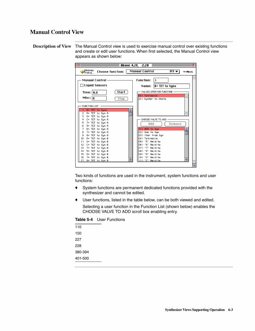
Synthesizer Views Supporting Operation 6-3
Manual Control View
Description of View The Manual Control view is used to exercise manual control over existing functions and create or edit user functions. When first selected, the Manual Control view appears as shown below:
Two kinds of functions are used in the instrument, system functions and user functions:
� System functions are permanent dedicated functions provided with the synthesizer and cannot be edited.
� User functions, listed in the table below, can be both viewed and edited.
Selecting a user function in the Function List (shown below) enables the CHOOSE VALVE TO ADD scroll box enabling entry.
Table 5-4 User Functions
110
150
227
228
380-394
401-500
Ready

6-4 Synthesizer Views Supporting Operation
Types of Functions Functions are of several types:
� Valve functions
� Non-valve hardware functions
� Logical or cycle directive functions
Valve functions, for example, simultaneously open a series of valves to perform a defined action during synthesis when executed from a cycle. The valves opened as part of a function remain open for the time specified in the cycle step or otherwise as controlled by software. See Appendix A for a complete listing and discussion of functions.
Areas of the ManualControl View
The Manual Control view provides three scrollable lists and a fourth area which allows turning on a function:
� The FUNCTION LIST indicates which function is currently displayed.
� The VALVES OPEN FOR FUNCTION list contains a valve listing for the current function, if that function opens valves.
� The CHOOSE VALVE TO ADD buttons are used to create user functions and contains a list of valves available for creating a new function.
� The fourth area enables manual control and is described in the procedure immediately below.
Exercising ManualControl of a
Function
The area on the upper left labeled Manual Control, allows you to turn on a selected function for a specified period of time and provides the option of using the liquid sensors with reagents delivered by the function. To use this portion of the table, follow these steps:
Viewing a FunctionValve List
To view the valve list associated with an existing function:
� Select the function to be viewed in the FUNCTION LIST, which contains a complete list of functions contained in the instrument.
Selecting a function on this list displays the list of associated valve openings (no valves are used in some functions) in the list entitled VALVES OPEN FOR FUNCTION and lists the number and name of the selected function in the two fields above the list (Function and Name).
Step Action
1 Select the function to be turned on in the Function List.
2 Enter the time during which the function operates in the Time entry field (optional for certain functions).
3 For functions which require a Misc entry, such as Functions 301–310 (Set Pres Reg), enter the appropriate value in this field.
4 Click Start to turn on the selected function for the specified time, if applicable.
5 If you want to stop the function before the time specified has elapsed, click Stop.

Synthesizer Views Supporting Operation 6-5
Creating a UserFunction
To create a user function, do the following:
Printing Functions The Manual Control View is one of several views from which printing can be done (others are the Edit Cycle views, the Edit Procedure views, and the Instrument Test view). As shown in the figure below, the print dialog box for the Manual Control view allows two main options, printing of function text or printing of the current Manual Control view window image.
If you choose the Text option, you can choose to print a single selected function, system or user, or choose to print all user functions. The function number and name are printed for all functions but valve numbers are printed only for system or user functions with associated valves. Functions with no associated valves (system or empty user functions) will have “None” printed for VALVES.
Note The User functions available are listed in the table on page 6-4.
Step Action
1 Select any of the functions in the list entitled “User Fxn” (see available numbers in the table on page 6-3) or functions in the range 401–500 (for user functions tied to sensors). (The function number will appear in the Function field and the Name field will become available for entry.)
Note Selecting an empty user function displays the function number in the Function field and the function name in the Name field. Nothing is listed in the VALVES OPEN list for an empty function or a non-value function.
2 Type a name for the new user function into the Name field.
3 Select the first valve to be added from the CHOOSE VALVE TO ADD list and then click the Add button to add the valve to the VALVES OPEN FOR FUNCTION list.
The CHOOSE VALVE TO ADD list is a complete list of valves used to create user functions.
4 Continue by selecting each valve to be added to the function in the correct order and then clicking the Add button. If you make an error, click the Remove button.
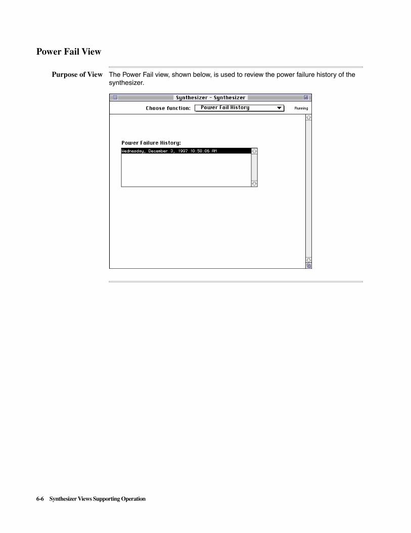
6-6 Synthesizer Views Supporting Operation
Power Fail View
Purpose of View The Power Fail view, shown below, is used to review the power failure history of the synthesizer.

Synthesizer Views Supporting Operation 6-7
Instrument Test View
The Instrument Test view pictured below is primarily intended for Service Engineer use. All tests in this view may be performed by the customer but interpretation of time, current, and valve status values is “service only.” If an explanation of these values becomes necessary, please ask your local field representative for interpretation.
Sensor status is intended for use by the customer and the service engineer. Once a sensor calibration is performed (in the Misc Procedures view), gas and liquid values are assigned for each of the twenty-three (there is no sensor #13) liquid sensors. The liquid value must be at least twice the gas value for each position in order for the calibration procedure to pass and for a Synthesis to start. Your local engineer or technical support representative may ask you to read off the sensor values when troubleshooting failed deliveries.
Note The Instrument Test View is one of several views from which printing can be done (others are the Edit Cycle views, the Edit Procedure views, and the Manual Control View.

6-8 Synthesizer Views Supporting Operation
B+ Tet Calibration
Contents of View The figure below contains the initial B+ Tet calibration values for your 3948 instrument. If this table is deleted or otherwise damaged in your instrument, it can be restored in one of two ways:
� Open the off-line copy of the database and then download the database using the Send to Synthesizer command.
� Open the off-line copy of the database and then use the opened database as a reference while you manually type in appropriate values.
Manual entry is made one field at time into the table in the ABI™ 3948 System Control application. Select each table field, i.e. B+TET to Col A, in a particular column and then enter the appropriate value in the time entry field at the bottom of the table.
The values provided in this table are used by the B+Tet function in the Synthesis module to provide a maximum time for delivering amidite from a bottle to a column position. For example, the Tet to Col value is the time (in seconds) for the washout with tetrazole of the synthesis valve block to ensure that there is no crossover amidite delivery between columns.
For more information on how the B+Tet function works, see the information in Appendix B, ABI 3948 Special Functions, under “1 B+TET to Syns” on page B-5.
Note The CPL (Coupling) Wait Time in the cycle waits between pushes during the coupling phase of synthesis.

Synthesizer Views Supporting Operation 6-9
Reagent Utilization Table View
Contents of View The figure below contains the initial Reagent utilization values for your ABI™ 3948 instrument. If this table is deleted or otherwise damaged in your instrument, it can be restored in one of two ways:
� Open the off-line copy of the database and then download the database using the Send to Synthesizer command.
� Open the off-line copy of the database and then use the opened database as a reference while you manually type in appropriate values.
Manual entry is made one field at time into the table in the ABI™ 3948 System Control application. Select each table field in a particular column and then enter the appropriate value in the volume entry field at the bottom of the table.
The values provided by this table are used to calibrate the Bottle Usage View so that the latter view can correctly indicate the amounts of reagents needed for the next run.
The volume values in the four columns are described in the following table:
Column Description
Base Volume consumed per addition of the specified base (from Positions AGCT and 5–8).
Cycle Volume consumed per synthesis cycle of specified reagents other than amidites.
Example: for a 20 mer oligo, total TCA consumption with be (20 x value in Cycle column) or 20 x 0.58 = 116 mL for that oligo.

6-10 Synthesizer Views Supporting Operation
Oligo Volume consumed of specified reagent on a per-oligo basis.
Example: for a run of 36 purified oligos,total consumption of TEAA will be1.01 x 36 = 36.36 mL for the entire run (1.01 mL per oligo).
Run Consumption of reagents used only once per run.
Column Description

Synthesizer Views Supporting Operation 6-11
Section 2 – Editing Cycle and Procedure Views
Topics Covered This section contains the following topics:
Edit Cycle and Procedure Interface 6-12
Seven Editing Views 6-12
Interface Elements 6-12
Same General Layout 6-12
Cycle and Procedure Pop-Up Menus 6-13
Buttons 6-14
Entry Fields 6-16
Edit Synthesis Cycle View 6-17
Purpose and Contents of View 6-17
Edit Cleavage Cycle View 6-18
Purpose and Contents of View 6-18
Edit Purification Cycle View 6-19
Purpose and Contents of View 6-19
Edit Begin Procedure View 6-20
Purpose and Contents of View 6-20
Edit End Procedure View 6-21
Purpose and Contents of View 6-21
Edit Bottle Procedure View 6-22
Purpose and Contents of View 6-22
Misc (Miscellaneous) Procedures View 6-23
Purpose and Contents of View 6-23

6-12 Synthesizer Views Supporting Operation
Edit Cycle and Procedure Interface
Seven Editing Views Seven views are available for editing existing procedures or cycles and creating new procedures or cycles:
� Edit Synthesis Cycle
� Edit Cleavage Cycle
� Edit Purification Cycle
� Edit Begin Procedure
� Edit End Procedure
� Edit Bottle Procedure
� Misc (Miscellaneous) Procedures
Interface Elements All seven editing views share the same interface elements:
� Pop-up menus
� Scroll boxes
� Buttons
� Entry fields, and
For a detailed procedure on how to use Edit views, see Section 6 in the ABI™User’s Manual (Advanced Use of 3948 System Control).
Note The Edit Cycle, Edit Procedure, Manual Control, and Instrument Test views are the only views which can be printed.
Same GeneralLayout
All Edit views have the same general layout as that shown for the Edit Cycle view example below. Refer to this figure in following the descriptions of the editor interface which follow:
x.xx
x.xx
,dyReady

Synthesizer Views Supporting Operation 6-13
Cycle and ProcedurePop-Up Menus
A pop-up menu displays available cycles or procedures to edit and presents the choices available for the particular view. For example, the Cycle menu on the Edit Synthesis Cycle view initially presents the pop-up menu shown below:
When you select one of the names on this type of menu, the contents of the cycle or procedure are listed in the main scroll box and the name is presented in the Name entry field. If you select a name representing a new cycle or procedure, the main scroll box initially has only Begin and End steps as shown in the figure below:

6-14 Synthesizer Views Supporting Operation
Buttons The following buttons are described in this subsection:
� Apply
� Copy from
� Execute
� Insert
� Safe/Sensor
Apply Button
Clicking the Apply Button updates the cycle with all the information entered into the previous fields. If there is an invalid entry, the Apply button will be grayed out until all the fields are correct.
Copy from Button
Once an empty cycle/procedure is selected, the Copy from Button becomes available:
� This button displays a dialog box like that shown below:
� Use the dialog box to copy any existing cycle from any open database as a template for creating a new cycle or procedure.
Initially, the dialog box shows only the standard cycle provided.
Note If you access a database containing several types of cycles or procedures, the dialog box shown above will only show the cycles or procedures which are relevant for the current type of edit view.
Execute Button
You can execute Begin, End, Bottle, and Shutdown procedures whenever the instrument is “Ready”. The button is grayed out to disable execution when the instrument is in any other mode.
In the Edit views for Synthesis, Cleavage/ deprotection, and Purification cycles, the Execute button is always grayed out to indicate that you cannot manually execute these cycles. The cycles are executed by the chemistry protocol assigned for instrument operation.
Dbase 4.20, 2.20: Syn v4.20

Synthesizer Views Supporting Operation 6-15
Insert Button
This button is used to insert new blank steps into the cycle listed to the right.
Safe/Sensor Buttons
These radio buttons allow you to designate, respectively, that a new step is not a safe step and that sensors are used for the step. (As defaults, a step is automatically designated as a safe step which does not use sensors.) Entries made with these buttons appear in the SAFE and SNS columns of the cycle table.
Only certain functions use liquid sensors as part of their operation.
Step Action
1 Select the step above your new step.
2 Click Insert.
As soon as Insert is clicked, a new blank line is added to the cycle or procedure listing and the cursor moves to the Function entry field
3 Select the function in one of two ways:
� Type in the function number in the Function field.
� Click the function you want to insert from the Function scroll box, shown below:
Note Clicking a function is often easier than typing in the function number.
As soon as a function is added as a step in the main scroll box, the new step is open for input using the remaining two entry fields, Time and Misc, and the two radio buttons, Safe and Sensor.
6-16 Synthesizer Views Supporting Operation
Entry Fields The following entry fields are described in this subsection:
� Function Entry field (Function Scroll Box)
� Misc Data Entry field
� Name Entry field
� Time Entry field
Function Entry Field/Function Scroll Box
The Function Entry field is used to add a function to new blank steps placed in the cycle or procedure in the main scroll box with the Insert Button. It requires that you know the associated number by heart.
The Function scroll box, shown in the figure on page 6-15, is an easier way to add a function to new blank steps since you can scroll until you identify the proper function.
Misc Data Entry Field
For some types of functions, an entry is required for this field to make an entry in the MISC column of the cycle table. For example, a loop index or a pressure setting can go in the MISC field. Refer to “Special Logical Functions” in Appendix A for information on how to set parameters for special functions.
Note If the Misc field is blank, the Apply button will remain grayed out (unavailable). All such fields require at least a zero.
Name Entry Field
This field displays the current name of the cycle selected from the Cycle menu. It initially has the name selected, as indicated by highlighting, allowing you to change the name.
Time Entry Field
After you have inserted a function as a step in the cycle, you need to enter the time for the new step in this entry field. Select the default “0.0” entry and type in the new value to enter it into the cycle table.

Synthesizer Views Supporting Operation 6-17
Edit Synthesis Cycle View
Purpose andContents of View
The Edit Synthesis Cycle view allows you to produce custom cycles to perform synthesis in the Synthesis module:
� The Edit Synthesis Cycle view initially appears as shown in the left side of the figure below.
� The Cycle pop-up menu, shown in the right side of the figure, is used to select an existing cycle or select a location for creating a new cycle.
The Synthesis Cycle pop-up menu can store up to 20 cycles. The first cycle is a permanent non-programmable cycle for use in the instrument. You can copy it into one of the other 19 locations labeled “Syn Cycle” and then edit it to create a custom cycle.
x.xx
x.xx
x.xx
,dyReady

6-18 Synthesizer Views Supporting Operation
Edit Cleavage Cycle View
Purpose andContents of View
The Edit Cleavage Cycle view allows you to produce custom cycles to perform cleavage at the Cleavage station and deprotection in the deprotection coils:
� The Edit Cleavage Cycle view initially appears as shown in the left side of the figure below.
� The Cycle pop-up menu, shown in the right side of the figure, is used to select an existing cycle or select a location for creating a new cycle.
The Cleavage Cycle pop-up menu can store up to 9 cycles besides the first cycle (which is a permanent non-programmable cycle). You can copy it into one of the other 9 locations labeled “Clv Cycle” and then edit it to create a custom cycle.
x.xxx.xx
x.xx
Ready
,

Synthesizer Views Supporting Operation 6-19
Edit Purification Cycle View
Purpose andContents of View
The Edit Purification Cycle view allows you to produce custom cycles to perform purification at the Purification station:
� The Edit Purification Cycle view initially appears as shown in the left side of the figure below.
� The Cycle pop-up menu, shown in the right side of the figure, is used to select an existing cycle or select a location for creating a new cycle.
The Purification Cycle pop-up menu can store up to 10 cycles. The first three cycles are permanent non-programmable cycles for use in the instrument:
� The first cycle is used for purification of regular oligonucleotides.
� The second cycle is used for purification of dye primer oligonucleotides.
� The third cycle is used for purification of biotin.
You can use any of these cycles “as is” or you can copy one of them into one of the 7 locations labeled “Pur Cycle” and then edit it to create a custom cycle.
x.xx
x.xxx.xxx.xx
x.xx
Ready
,

6-20 Synthesizer Views Supporting Operation
Edit Begin Procedure View
Purpose andContents of View
The Begin procedure provided with the instrument is a phosphoramidite purge procedure that fills all phosphoramidite and tetrazole delivery lines (from the reservoir to the reagent valve block) with fresh reagent. You should use the begin procedure prior to beginning a run or if one of the phosphoramidite reservoirs has not been accessed within 12 hours.
The Edit Begin Procedure View allows you to produce custom Begin procedures to prepare for a run:
� The Edit Begin Procedure view initially appears as shown in the left side of the figure below.
� The Cycle pop-up menu, shown in the right side of the figure below, is used to select an existing begin procedure or select a location for creating a new procedure.
The application can store up to 9 procedures besides the permanent non- programmable procedure provided. You can use the Begin procedure “as is” or you can copy it into one of the other 9 locations labeled “Beg Proc” and then edit it to create a custom procedure.
x.xx
x.xxx.xx
x.xx
Ready
,

Synthesizer Views Supporting Operation 6-21
Edit End Procedure View
Purpose andContents of View
An End procedure, shown below, is used to flush and clean out the system at the end of a run.
� The Edit End Procedure view initially appears as shown in the left side of the figure below.
� The End Procedure popup menu, shown in the right side of the figure, is used to select an existing cycle or select a location for creating a new cycle.
The application can store up to 9 procedures besides the standard end procedure provided. The standard end procedure is a permanent non-programmable cycle. You can use this procedure “as is” or you can copy it into one of the other 9 locations labeled “End Proc” and then edit it to create a custom procedure.
x.xx
x.xx
Ready
,
x.xx

6-22 Synthesizer Views Supporting Operation
Edit Bottle Procedure View
Purpose andContents of View
Bottle change procedures are used to autodilute amidites or remove empty bottles and replace them with bottles of fresh reagents. These procedures are used either before beginning a synthesis or when an active synthesis has been interrupted. Change procedures are especially important for phosphoramidite and tetrazole bottles because they are the most sensitive to atmospheric oxygen and water.
As shown in the Procedure pop-up menu in the right side of the figure above, fifteen non-programmable procedures are provided. The first five procedures, autodilution procedures for amidites, include:
� The “AutodiluteACCT” procedure which autodilutes amidites simultaneously at all four standard positions (positions 1 through 4)
� A separate autodilution procedure for each of the four standard amidite positions.
The next ten procedures, bottle change procedures, include:
� Procedures for use in changing the bottles at the four standard positions (positions 1 through 4)
� Procedures for ammonia and tetrazole bottles
� Procedures for manually diluted monomers in positions 5 through 8.
The user-defined procedures, labeled “Bottle Proc.,” are for use in creating a modified form of one of the standard procedures.
x.xxx.xxx.xxx.xx
x.xxx.xx
x.xx)
,
x.xx
X.XX
X.XX
x.xx
x.xxx.xxx.xx
x.xxx.xx
x.xxx.xx
x.xx
Ready

Synthesizer Views Supporting Operation 6-23
Misc (Miscellaneous) Procedures View
Purpose andContents of View
This view contains various procedures needed for system maintenance or to shut down the instrument to prepare for long-term storage (storage for periods of one month or longer). Procedures such as “Clean Cols” and “Clean Lines” are useful for both maintenance or shutdown since they remove all reagents in the delivery lines and wash and dry all chemical pathways.
One of the procedures provided with the synthesizer, “Prime Amidites”, is the initial Misc Procedures View and is used to prime phosphoramidite delivery lines in the instrument after using the cleaning procedures or when restoring a shut down instrument for regular use.
Note Hardware Test vx.xx is a procedure used to implement hardware tests for the Instrument Test View and can not be executed from the Misc Procedures View even though the Execute button is active.
As you can see by examining the Cycle pop-up menu, the following types of procedures are permanent non-programmable cycles for use in the instrument:
� Procedures for cleaning, priming and hardware testing
� Procedures for calibrating sensors, verifying sensor calibration, and setting pressures
� Procedures for emptying ACN lines, and testing the sample collector and pressure module
Note The Janitor procedure provides more complete instrument cleanup.
You can use these procedure “as is” or you can copy one of them into an empty procedure slot and then edit it to create a custom procedure.
Note For information on shutting down the instrument, refer to “Shutting Down and Restoring the Instrument” on page 5-5 of the ABI ™ 3948 System User’s Manual.
x.xx
x.xxx.xxx.xx
,Ready
x.xx
x.xxx.xx
x.xx
x.xxx.xx
x.xx
x.xx
x.xx


Valves and Functions A-1
Valves and Functions A
In This Appendix
Topics Covered This appendix contains the basic information needed to understand ABI 3948 System Functions, Cycles, and Procedures. For detailed information on ABI 3948 System Special Functions, see Appendix B. For detailed information on ABI™ 3948 System cycles and procedures, see Appendix C. For a detailed listing of ABI™3948 System function information, see Appendix D. Appendix E provides a plumbing diagram for use in tracing function, cycle, and procedure reagent flow paths.
This appendix covers the following topics.
Topic See page
Information on ABI 3948 System Chemistry Terminology A-3
Introduction A-3
Definition of Functions, Steps, Cycles, Protocols, and Procedures A-3
Chemistry Stages on the ABI 3948 System A-3
Valves A-5
List of Valves A-5
Overview of Functions A-7
Introduction A-7
Function Names A-7
Time and Misc Field Entries or Subroutines A-7
Tracing Flow Paths for Functions A-8
Valve Functions A-10
Types of Valve Functions A-10
Uses of Valve Functions A-10
Manual Control A-10
Creating Your Own Functions A-10
Sensors A-11
General Characteristics A-11
Location of Sensors A-11
Retries A-12
Description of User Functions A-12
Components of Sensor-Controlled User Functions A-12
Names and Locations of Sensors A-13
A

A-2 Valves and Functions
Use of Parallel with Serial User Functions A-13
Sensor-Controlled User Function Example A-14
Valve Functions by Functional Category A-15
List of Function Categories A-15
Synthesis Valve Functions A-15
Synthesis Column Flushing and Back Flushing Functions A-16
Cleavage Functions A-17
Purification and Quantitation Functions A-18
Bottle Change Functions A-20
User Functions A-20
Block Functions A-21
Non-Valve Hardware Functions A-23
Overview A-23
Pressure Regulating Functions A-23
Calibration Functions A-23
Turntable Control Functions A-23
Miscellaneous Hardware Functions A-24
Jaw Functions A-24
Sample Collector Functions A-24
Overview of Special Functions A-25
Introduction A-25
Topic See page

Valves and Functions A-3
Information on ABI 3948 System Chemistry Terminology
Introduction This section contains information essential to understanding functions, the three types of cycles (Synthesis, Cleavage/Deprotection, and Purification) and procedures.
Automated production of oligonucleotides on the ABI™ 3948 System requires chemical deliveries to specified destinations on the instrument. These deliveries are controlled by electrically activating valves that open and close, creating various pathways through the ABI™ 3948 System.
Definition ofFunctions, Steps,
Cycles, Protocols,and Procedures
Each valve is assigned a number that can be used to open or close it. Most functions consist of a valve or set of valves that open to perform a specific delivery or task.
For example, Function 27, Cap to Syn Cols, delivers capping solution simultaneously to all three synthesis columns. To accomplish this, Function 27 opens valves 13, 14, 15, 16, 17, 18, 22, 24, 25, and 26 simultaneously. Other functions control hardware systems such as the turntable or control the flow of cycle execution.
A function is an individual action which may have Time and Misc (Miscellaneous) fields. Functions can be activated manually in the Manual Control view or may be programmed as steps in cycles (for example, Function 27 is activated for 15 seconds in the standard synthesis cycle).
A cycle contains a series of steps that perform a chemical process. The ABI™ 3948 uses three types of cycles to produce oligonucleotides:
� Synthesis cycles, to add bases
� Cleavage/Deprotection cycles, to cleave oligonucleotides from column supports and then deprotect them
� Purification cycles, to purify and quantitate or produce crude oligonucleotides for output to the sample collector
A protocol consists of three cycles and contains all the chemical steps needed to produce an oligonucleotide.
A Procedure is a series of steps that completes a task, such as changing a reagent bottle. Upon command, the steps are performed once and are not repeated. There are four types of operating procedures: begin, end, bottle and miscellaneous.
Chemistry Stages onthe 3948
The Synthesis, Cleavage/Deprotection, and Purification cycles are performed for each oligonucleotide:
Stage Description
1 First, the Synthesis cycle synthesizes the oligonucleotides in the first row on OneStep™ columns at the Synthesis jaw.
2 At the second stage, the turntable moves the oligonucleotide-containing columns to the Cleavage jaw.
The Cleavage/Deprotection cycle cleaves the oligonucleotides from the OneStep column in the jaw and transfers them to the deprotection coils to be deprotected.
3 In the third stage, the columns move to the Purification jaw where deprotection is completed and the deprotected oligonucleotides are purified or collected as crude product.
A-4 Valves and Functions
Every time one row of columns moves to the next station, the subsequent row of columns moves to the station just vacated. As the first row of oligonucleotides is being cleaved at the second station, the second row of oligonucleotides is undergoing synthesis at the first station.
When the second row in turn moves to the second station, the third row of columns moves to the first station, and so on. This concurrent use of three stations with three different, sequential cycles executing in parallel enables the high throughput of the ABI 3948 Synthesis/Purification system.

Valves and Functions A-5
Valves
List of Valves During a synthesis, valves are automatically opened to create chemical pathways and allow all necessary reagent and gas deliveries. You can also manually operate valves in the Manual Control View before or after a synthesis or when a synthesis has been interrupted.
Table A-1 lists all valves with brief descriptions of the associated gas or reagent flow. Appendix D provides more detailed schematic information. Refer to “Delivery Valve Blocks” in Chapter 2 for a physical description of the valves.
Note To identify reagent valve blocks, see the plumbing diagram for the instrument in Appendix D.
Table A-1 Valves with Associated Reagents and Gas Flows
Block or Valve Type
Valve Reagent or Gas Flow Block or Valve Type
Valve Reagent or Gas Flow
A 12345678
ACN to SynGas to SynXfr from SynTetrazole“5” amidite“6” amidite“7” amidite“8” amidite
E 2930313233343536
Gas to Clv LowerXfr to Clv LowerH2O to Clv Lower
AmmoniaClv Col C LowerClv Col B LowerClv Col A LowerUnused Valve 36
B 910111213141516
“A” amidite“G” amidite“C” amidite“T” amiditeSyn Col C Lower Syn Col B LowerSyn Col A LowerXfr to Syn Low
F 37383940414243
Gas to Dep LowerACN to Dep LowerXfr Clv to DepCoil A Input Coil B Input Coil C Input Dep Low to Waste
C 1718192021
NMIAc20TCAIodineSyn Low to Waste
G 44454647484950
Gas to Dep UpperH2O to Dep Upper
Coil A Exit Coil B Exit Coil C Exit Xfr from DepDep Upr to Waste
D 22232425262728
Syn Upr to WasteSyn Upr Hal WasteSynthesis Col C UpperSynthesis Col B UpperSynthesis Col A UpperPMS VentGas to Syn Upper
H 5152535455
Gas to PurACN to PurTEAA TFA Ac Acid
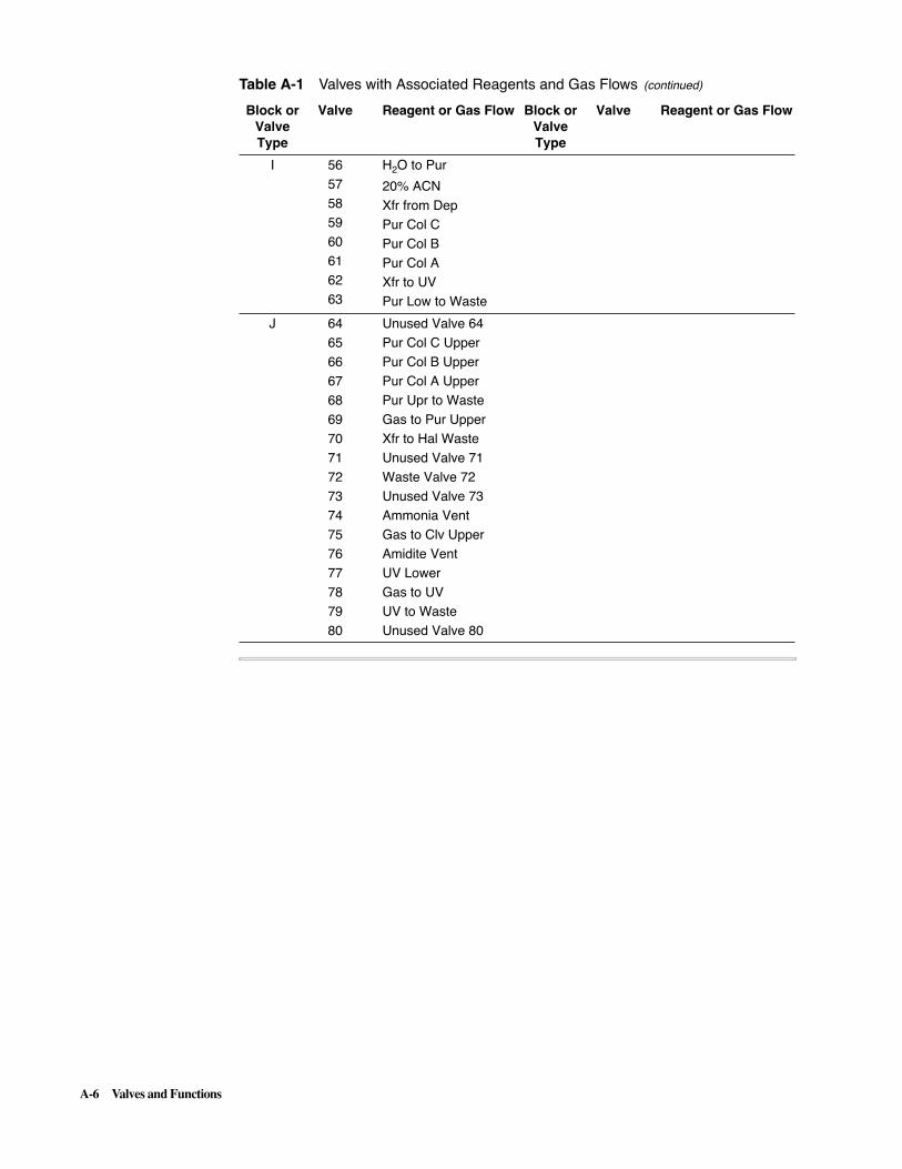
A-6 Valves and Functions
I 5657585960616263
H2O to Pur
20% ACNXfr from DepPur Col CPur Col B Pur Col AXfr to UVPur Low to Waste
J 6465666768697071727374757677787980
Unused Valve 64Pur Col C UpperPur Col B Upper Pur Col A Upper Pur Upr to WasteGas to Pur UpperXfr to Hal WasteUnused Valve 71Waste Valve 72Unused Valve 73Ammonia VentGas to Clv UpperAmidite VentUV LowerGas to UVUV to WasteUnused Valve 80
Table A-1 Valves with Associated Reagents and Gas Flows (continued)
Block or Valve Type
Valve Reagent or Gas Flow Block or Valve Type
Valve Reagent or Gas Flow

Valves and Functions A-7
Overview of Functions
Introduction The permanent non-programmable functions available on the instrument are considered “System” functions to distinquish them from another function category provided on the instrument, “User” functions. More information on User functions is provided below and later on in this appendix.
System Functions
There are three fundamental types of functions on the ABI 3948 System:
� Valve functions that deliver reagents and gas throughout the system
� Non-valve hardware functions that control parts of the ABI 3948 System such as the turntable, pressure regulators, or sample collector
� Logical or cycle directive functions such as Begin Loop, Select Pur Cols, or If Cyc Greater.
Logical functions help to define the behavior of other functions or affect the flow of control through the steps in a cycle
Each of the three types of functions above are covered separately as sections in this appendix.
User Functions
Two types of User functions are provided on the instrument. One type is considered a general purpose valve function and the other type is a special User function that can perform sensor-controlled deliveries. Information on creating these types of User functions is provided in Chapter 6 under “Creating a User Function” on page 6-5.
Because the sensor-controlled User functions are a special type needing separate discussion. more information on them is provided under “Description of User Functions” on page A-12
Function Names Functions have abbreviated names which describe the action they perform. For example, Function 44, ACN to SynCol A, delivers acetonitrile to Column A. You can trace the pathway created by activating Function 44 on the simplified synthesizer module schematic shown in Figure A-1.
The third class of functions, Special Logical (Cycle Directive) functions, are functions whose behavior cannot be anticipated by relating the function name to the instrument's reagents or mechanical components.
Time and Misc FieldEntries or
Subroutines
In all cases, the Time and Misc fields are used as follows:
� The Time field uses a time in seconds and tenths of a second.
� The Misc (Miscellaneous) field is used to declare any other type of step parameter such as a pressure or temperature setting.
Sometimes a function's behavior is modified simply by having a non-zero instead of a zero in the Miscellaneous field. In these cases, any non-zero value will work. ABI cycles use 999 with these functions to distinguish between “non-zero” and the specific values required by other functions.

A-8 Valves and Functions
Tracing Flow Pathsfor Functions
To understand how the instrument performs the process of synthesis, compare the Synthesis cycle listing provided in Appendix B and the plumbing diagram on page A-9 with the following function lists:
� Table A-2 on page A-15
� Table A-3 on page A-16
To understand the process of cleavage/deprotection, compare the Cleavage/Deprotection cycle listing provided in Appendix B and the appropriate portions of the synthesizer schematic in Appendix D with the following function lists:
� Table A-3 on page A-16
� Table A-4 on page A-17
� Table A-5 on page A-17
� Table A-6 on page A-18
� Table A-7 on page A-18
To understand the process of purification/quantitation, compare the purification cycle listing provided in Appendix B and the appropriate portions of the synthesizer schematic in Appendix D with the following function lists:
Table A-8 on page A-18
Table A-9 on page A-19
Table A-10 on page A-19
To achieve reagent flow, specific valves must open simultaneously so that the following occurs:
� The pathway from the pressurized bottle to the valve block is opened.
� An exit is provided out of the valve block to waste, or to the column and then to either the waste port or the collection vial.
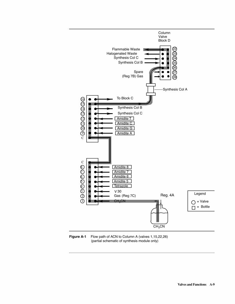
Valves and Functions A-9
Figure A-1 Flow path of ACN to Column A (valves 1,15,22,26)(partial schematic of synthesis module only)
24
22
23
25
26
27
28
14
15
16
13
12
11
10
9
8
65
432
1
A
B
7
CH3CN
Tetrazole
Legend
= Valve
= Bottle
Synthesis Col A
Gas
(Reg 7B) Gas
CH3CN
Column ValveBlock D
Amidite 5
Reg. 4A30V
Amidite 6
Amidite 8Amidite 7
C
C
Synthesis Col B
Synthesis Col C
Amidite TAmidite CAmidite GAmidite A
To Block C
Spare
Halogenated Waste
Synthesis Col BSynthesis Col C
Flammable Waste
(Reg 7C)

A-10 Valves and Functions
Valve Functions
Types of ValveFunctions
There are three basic types of valve functions:
� Block functions - which do not deliver to columns or coils
� Serial functions - which deliver to a specific column or coil and will only execute if their designated column is active
� Parallel functions - which, within a given area such as cleavage, deliver to all active columns or coils at the same time
In an instance where only a single column is active, a parallel function will behave like the corresponding serial function dedicated to that one column.
Associated parallel and serial functions are always clustered together on the function list in the order: Parallel Function, Serial A, Serial B, Serial C.
Uses of ValveFunctions
Valve functions do the following:
� Direct the reagent deliveries in the Synthesis, Cleavage/Deprotection, and Purification cycles that are necessary to produce oligonucleotides on the 3948.
� Constitute the following procedures: bottle change, auto-dilution, begin, end, miscellaneous, and flow test.
These procedures as well as the three types of chemistry cycles are documented further on in this appendix.
A valve function works by opening or closing a valve or set of valves simultaneously to perform a specific delivery or task for a specified time, such as deliver reagents: Reagents delivered in this way flow through the column and then to either the waste bottle, deprotection coils, or the UV detector and the collection vial.
Manual Control Valve functions are used automatically by the system to perform chemistry or other tasks when you run a procedure or a chemistry protocol. If you desire, you can manually activate valves as well as other types of functions using the Manual Control view whenever the instrument is not active.
Creating Your OwnFunctions
Besides activating functions which are already defined, the ABI™ 3948 System provides you with the capability of creating your own functions. As described under “Exercising Manual Control of a Function” on page 6-4, you can create more than 100 user-defined functions in the Manual Control View and combine them with the standard set of functions to customize procedures.
Customized procedures may also be executed from within the Edit view used to create them (see Execute Button on page 6-14). During synthesis, the Monitor Chemistry menu displays each function as it is activated. For information on creating your own sensor-controlled functions, see “Description of User Functions” on page A-12.

Valves and Functions A-11
Sensors
GeneralCharacteristics
Valve functions may be sensor controlled or not and work as follows:
Note With Flush and Back Flush functions, sensors are used to detect dryness. All other sensor functions execute until the sensor becomes wet.
Location of Sensors Sensors are located in these places:
Characteristic Description
Serial and Parallel compared to block
All serial and parallel functions work with liquid/gas sensors while block functions do not.
Execution by time or sensor
Sensor functions execute for the time specified in the step unless their sensor is activated (i.e., the step field “SNS” equals YES).
In this case, execution stops either when the sensor is triggered or when the time runs out, whichever occurs first (see the discussion under “Retries” below).
Parallel functions Parallel functions turn off the delivery to each column or coil separately as each different sensor triggers.
Location Description
Above jaw positions
On flow paths through the jaws that clamp on the OneStep™ columns, primarily above the columns to detect the deliveries of reagents through the columns.
The sensors above the columns are also used to verify that columns have been flushed dry with gas or that the cleavage or purification vessels have been drained (back flushed) until empty.
Below synthesis jaw positions
Between the reagent block and columns in the synthesis module to minimize the consumption of expensive amidites.
These sensors allow the delivery of short slugs of reagent that are then pushed into position to saturate the columns. The upper synthesis sensors control this final push so that it is stopped at the right time to leave these short slugs resting over the columns.
Near amidite bottles
On flow paths out of the primary amidite bottles (A, G, C, and T — bottles 1 through 4) to verify deliveries out of these bottles.
Near deprotection coils
On flow paths through the three deprotection coils to detect the arrival of samples into the coils.
Near the UV cell On the flow path through the UV cell to detect the arrival of a sample at the cell.

A-12 Valves and Functions
Retries Retries work as listed below:
Description of UserFunctions
The last 100 functions on the ABI 3948 System function list (SynUpr Wet 401 to 500 UV Dry 500) are user functions that can perform sensor-controlled deliveries. User functions have the following characteristics:
The particular sensor or set of sensors tied to a sensor user function is specified in the default function name. As with standard user functions, the function name may be edited as well as the valve list.
Components ofSensor User
Function Names
There are three components to the default names provided for sensor user functions:
Characteristic Description
Number of retries Any function executing with sensor(s) active will retry a delivery or dry up to six times if the sensor does not report success initially (except Base+Tet).
Any function that retries more than four times will issue a message to serve notice that trouble may be developing.
Note Ramping functions will retry only four times instead of the usual six and do not report retries, only failure
Execution until time elapses or trigger occurs
Each retry executes for as long as the time specified unless the sensor triggers during the retry and ends the function.
Fifteen seconds Delivery functions will wait fifteen seconds between retries to ensure bottle repressurizing between attempts.
Back flushes and drains
Drying functions (back flushes/drains and flushes) do not wait between retries.
Parallel functions Parallel functions will retry only those columns that have not already been successful and may retry each column a different number of times.
Characteristic Definition
Valve lists defined by operator
Like standard user functions, the valve list for these functions can be defined by the operator.
Sensors are pre-assigned
These functions offer the additional advantage of having sensors pre-assigned to them.
Engaged by YES in SNS field
Sensors are engaged in the usual fashion by setting the SNS field in the step to YES.
Components Description
1 The first part of the default name identifies the sensor or sensors associated with the function.
2 The second component spells out whether the function is ‘wet’ or ‘dry,’ that is, whether the function's sensor(s) trip upon detecting wetness (liquid delivery) or dryness (gas delivery, flush or back flush).
3 The final component of the default function name, in keeping with the convention for standard user functions, is the function number.

Valves and Functions A-13
Names andLocations of Sensors
Sensors have the following names and locations:
See the Plumbing Diagram in Appendix D of this manual to verify which sensors are associated with which columns. In some instances, the column alphabetic order and sensor numeric order are reversed.
Use of Parallel withSerial Sensor User
Functions
As with other sensor functions, parallel sensor user functions are always grouped on the function list together with their associated serial functions. So SynUpr Wet 401 is followed by SynUprWet A 402, SynUprWet B 403, and SynUprWet C 404.
This grouping of sensor functions into sets is crucial to the operation of parallel user functions:
User definable functions operate according to the same scheme as follows.
� To program the valve list for a parallel user function, enter the appropriate valve lists for each associated serial function.
� To aid in documenting the valve assignments made for serial functions associated with a parallel user function, enter the complete three-column valve list for the serial functions into the listing for the parallel function.
The entire valve list may then be viewed under one function, the parallel function, in Manual Control.
Sensor Name/Number Location
SynUpr 1, 2, 3 Sensors with these designations are upper synthesis sensors.
SynMan 22, 23, 24 Sensors with these designations are synthesis manifold sensors.
SynLow 4, 5, 6 Sensors with these designations are lower synthesis sensors.
Clv 10, 11, 12 Sensors with these designations are cleavage sensors.
Coil 10, 11, 12 Sensors with these designations are coil sensors.
Pur 14, 15, 16 Sensors with these designations are purification sensors.
UV 21 This is the UV sensor.
Characteristic Description
Parallel use serial function valve lists
Parallel sensor-controlled functions do not use their own valve lists to execute, but use the valve lists of their associated serial functions instead.
Parallel turn on only valves for active columns
Parallel sensor-controlled functions turn on only the valves for active columns by merging together the valve list for each active column's associated serial function and excluding the valve lists of functions associated with inactive columns.
Valves for each column act independently
When one column finishes its delivery before the others, its single set of valves is deactivated. Any other active columns' valves will remain on until their sensors trigger.
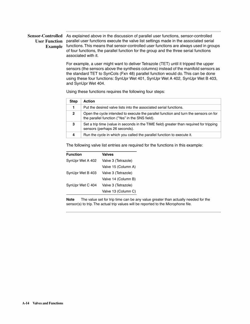
A-14 Valves and Functions
Sensor-ControlledUser Function
Example
As explained above in the discussion of parallel user functions, sensor-controlled parallel user functions execute the valve list settings made in the associated serial functions. This means that sensor-controlled user functions are always used in groups of four functions, the parallel function for the group and the three serial functions associated with it.
For example, a user might want to deliver Tetrazole (TET) until it tripped the upper sensors (the sensors above the synthesis columns) instead of the manifold sensors as the standard TET to SynCols (Fxn 48) parallel function would do. This can be done using these four functions: SynUpr Wet 401, SynUpr Wet A 402, SynUpr Wet B 403, and SynUpr Wet 404.
Using these functions requires the following four steps:
The following valve list entries are required for the functions in this example:
Note The value set for trip time can be any value greater than actually needed for the sensor(s) to trip. The actual trip values will be reported to the Microphone file.
Step Action
1 Put the desired valve lists into the associated serial functions.
2 Open the cycle intended to execute the parallel function and turn the sensors on for the parallel function (“Yes” in the SNS field).
3 Set a trip time (value in seconds in the TIME field) greater than required for tripping sensors (perhaps 26 seconds).
4 Run the cycle in which you called the parallel function to execute it.
Function Valves
SynUpr Wet A 402 Valve 3 (Tetrazole)
Valve 15 (Column A)
SynUpr Wet B 403 Valve 3 (Tetrazole)
Valve 14 (Column B)
SynUpr Wet C 404 Valve 3 (Tetrazole)
Valve 13 (Column C)

Valves and Functions A-15
Valve Functions by Functional Category
List of FunctionCategories
Valve functions are listed by functional category within this section. The third column of the function table for each category is used to indicate the type of Valve function (a blank, no entry, indicates a Serial function, Parallel indicates a Parallel Function, Ramping indicates a Ramping Function, and Block indicates a Block Function.
Note The functions in this category are used together with Non-valve Hardware functions and Logical or Cycle Directive functions to perform instrument chemistry.
To understand how valve functions work in a particular chemistry cycle, refer to the chemistry cycle listing in Appendix B and the material entitled “Special Functions” in this appendix to understand how the instrument performs chemistry. The Plumbing Diagram is provided in Appendix D to aid you in tracing out chemistry flow paths.
This section categorizes functions in the following areas:
� Synthesis Valve Functions
� Synthesis Column Flushing and Back Flushing Functions
� Cleavage Functions
� Purification Functions
� Bottle Change Functions
� User Functions
� Purification and Quantitation Functions
� Block Functions
Synthesis ValveFunctions
Table A-2 shows the Synthesis functions used for reagent deliveries to columns in synthesis jaws.
Table A-2 Synthesis Functions
Func.Number Function Name
Parallel/Block/Special Func.
Func.Number Function Name
Parallel/Block/Special Func.
1 B+ TET to Syns See “Special” functions.
17 8+ TET to Syn B
2 A+ TET to Syn A 18 A+ TET to SynC
3 G+ TET to Syn A 19 G+ TET to Syn C
4 C+ TET to Syn A 20 C+ TET to Syn C
5 T+ TET to Syn A 21 T+ TET to Syn C
6 5+ TET to Syn A 22 5+ TET to Syn C
7 6+ TET to Syn A 23 6+ TET to Syn C
8 7+ TET to Syn A 24 7+ TET to Syn C
9 8+ TET to Syn A 25 8+ TET to Syn C
10 A+ TET to Syn B 26 Coupling Wait See “Special” functions
11 G+ TET to Syn B 27 CAP to Syn Cols Parallel
12 C+ TET to Syn B 28 CAP to SynCol A
13 T+ TET to Syn B 29 CAP to SynCol B
14 5+ TET to Syn B 30 CAP to SynCol C

A-16 Valves and Functions
Synthesis valve functions provide for flow of reagents (driven by argon pressure) from the reservoirs, through valve blocks A, B, or C, through the OneStep columns, where all chemical reactions necessary for synthesis occur.
Two other types of functions, Flushing and Back Flushing, although they do not deliver reagents, are essential to Synthesis. These functions perform tasks such as flushing and back flushing columns (see Table A-3 below).
Synthesis ColumnFlushing and BackFlushing Functions
The functions in Table A-3 flush and back flush synthesis columns:
15 6+ TET to Syn B 33 IODINE to Syns Parallel
16 7+ TET to Syn B 34 IODINE to Syn A
37 IODINE to Waste Block 45 ACN to SynCol B
38 TCA to Syn Cols Parallel 46 ACN to SynCol C
39 TCA to SynCol A 47 ACN to SynWaste Block
40 TCA to SynCol B 48 TET to Syn Cols Parallel
41 TCA to SynCol C 49 TET to SynCol A
43 ACN to Syn Cols Parallel 50 TET to SynCol B
44 ACN to SynCol A 51 TET to SynCol C
Table A-2 Synthesis Functions (continued)
Func.Number Function Name
Parallel/Block/Special Func.
Func.Number Function Name
Parallel/Block/Special Func.
Table A-3 Synth-Gas Flushes and Back Flushes
FunctionNumber Function Name
Parallel/Block/Special Function
53 Flush Syn Cols Parallel
54 Flush Syn Col A
55 Flush Syn Col B
56 Flush Syn Col C
57 Back Flush Syns Parallel
58 Back Flush Syn A
59 Back Flush Syn B
60 Back Flush Syn C
61 Trityl Flush Syn Block
62 TritylFlsh SynA
63 TritylFlsh SynB
64 TritylFlsh SynC
65 SynLowBlk Flush Block

Valves and Functions A-17
Cleavage Functions The following tasks are performed by functions listed in this section:
� Delivery to Clv Cols (Table A-4)
� Gas Flushes and Pressurization (Table A-5)
� Oligonucleotide Transfer (Table A-6)
� Water Deliver to Deprotection Coil (Table A-7)
Delivery to Cleavage Columns
The functions listed in Table A-4 prime delivery lines and deliver reagents to cleavage columns.
Gas Flushes and Pressurization
The functions listed in Table A-5 flush and back flush cleavage columns and deprotection coils:
Table A-4 Functions for Delivery of Reagents to Clv Cols
Func.Number Function Name
Parallel/Block/Special Func.
Func.Number Function Name
Parallel/Block/Special Function
111 Ammonia to Clvs Parallel 126 H2O to Clv Cols Parallel
112 Ammonia to ClvA 127 H2O to ClvCol A
113 Ammonia to ClvB 128 H2O to ClvCol B
114 Ammonia to ClvC 129 H2O to ClvCol C
115 Ammonia toWaste Block 130 H2O to ClvWaste Block
116 ACN to Clv Cols Parallel
117 ACN to Clv A
118 ACN to Clv B
119 ACN to Clv C
120 ACN to ClvWaste Block
Table A-5 Functions for Gas Flushes and Pressurization
Func.Number Function Name
Parallel/Block/Special Func.
Func.Number Function Name
Parallel/Block/Special Function
121 Gas to Clv Cols Parallel 134 Back Flsh Clv C
122 Gas to ClvCol A 138 Press Line Block
123 Gas to ClvCol B 144 Clv Blk Flush Block
124 Gas to ClvCol C 153 DepLowBlk Flush Block
125 Gas to Clv II Block 155 Gas toDep Coils Parallel
131 Back Flush Clvs Parallel 156 Gas to Coil A
132 Back Flsh Clv A 157 Gas to Coil B
133 Back Flsh Clv B 158 Gas to Coil C

A-18 Valves and Functions
Oligonucleotide Transfer
The functions listed in Table A-6 transfer oligonucleotides from the cleavage columns into the deprotection coils.
Water Delivery to Deprotection Coil
The functions listed in Table A-7 deliver water to the deprotection coils:
Purification andQuantitation
Functions
The following tasks are performed by functions listed in this section:
� Delivering Reagents to Purification Columns/UV Detector (Table A-8)
� Rinsing and Flushing Deprotection Columns (Table A-9)
� Collecting and Quantitating Samples (Table A-10)
Delivery of Reagents to Purification Columns/UV Detector
The functions listed in Table A-8 deliver reagents to the purification columns and the UV detector.
Table A-6 Functions for Oligonucleotide Transfer
Func.Number Function Name
Parallel/Block/Special Func.
Func.Number Function Name
Parallel/Block/Special Function
141 Xfer Clv Col A 153 DepLowBlk Flush Block
142 Xfer Clv Col B 154 Dep Upr Blk Rinse
Block
143 Xfer Clv Col C 166 Xfr Coil A Ramping
151 Dep Xfer Rinse Block 167 Xfr Coil B Ramping
152 Dep Xfer Flush Block 168 Xfr Coil C Ramping
Table A-7 Functions to Deliver Water to Deprotection Coils
FunctionNumber Function Name
163 H2O to Coil A
164 H2O to Coil B
165 H2O to Coil C
Table A-8 Functions Delivering Reagents to Pur. Columns/UV Detector
Func.Number Function Name
Parallel/Block/Special Func.
Func.Number Function Name
Parallel/Block/Special Func.
173 ACN to Pur Cols Parallel 190 TFA to PurCol B
174 ACN to Pur ColA 191 TFA to PurCol C
175 ACN to Pur ColB 193 20%ACN to Purs Parallel
176 ACN to Pur ColC 194 20%ACN to Pur A
177 ACN to PurWaste Block 195 20%ACN to Pur B
178 TEAA to PurCols Parallel 196 20%ACN to Pur C
179 TEAA to Pur A 197 20%ACN to Waste
180 TEAA to Pur B 198 AcAcid to Purs Parallel
181 TEAA to Pur C 199 AcAcid to Pur A
182 TEAA to Waste Block 200 AcAcid to Pur B

Valves and Functions A-19
Rinsing and Flushing Deprotection Columns
The functions in Table A-9 rinse and flush the deprotection columns:
Collecting and Quantitating Samples
The functions listed in Table A-10 collect and quantitate samples:
183 H2O to Pur Cols Parallel 201 AcAcid to Pur C
184 H2O to PurCol A 202 AcAcid to Waste Block
185 H2O to PurCol B 211 Pur A to UV
186 H2O to PurCol C 212 Pur B to UV
188 TFA to Pur Cols Parallel 213 Pur C to UV
189 TFA to PurCol A 214 H2O to UV Block
Table A-9 Functions for Rinsing and Flushing Deprotection Columns
Func.Number Function Name
Parallel/Block/Special Func.
Func.Number Function Name
Parallel/Block/Special Func.
171 Pur Xfer Rinse Block 208 Back Flsh Pur A
172 Pur Xfer Flush Block 209 Back Flsh Pur B
203 Gas to Pur Cols Parallel 210 Back Flsh Pur C
204 Gas to PurCol A 218 PurLowBlk Flush Block
205 Gas to PurCol B 219 PurUprBlk Flush Block
206 Gas to PurCol C 220 Pur Vent Block
207 Back Flush Purs Parallel 222 SC Block Flush Block
Table A-10 Functions for Collecting and Quantitating Samples
FunctionNumber Function Name
Parallel/Block/Special Function
135 Crude A to UV Ramping
136 Crude B to UV Ramping
137 Crude C to UV Ramping
211 Pur A to UV Ramping
212 Pur B to UV Ramping
213 Pur C to UV Ramping
215 Xfer UV to SC Block
217 Flsh UV toWaste Block
Table A-8 Functions Delivering Reagents to Pur. Columns/UV Detector (continued)
Func.Number Function Name
Parallel/Block/Special Func.
Func.Number Function Name
Parallel/Block/Special Func.

A-20 Valves and Functions
Bottle ChangeFunctions
The functions listed in Table A-11 are used during bottle change procedures:
User Functions User Functions are a reserved class of valve function which enables the user to define functions using any valve listed in the Manual Control View. The empty functions listed in Table A-12 are available for user definition:
Note The functions in the range 401–500 are discussed under “Description of User Functions” on page A-12.
Table A-11 Bottle Change Functions
Func.Number Function Name
Func.Number Function Name
82 ACN AMIDITE A 95 Mix AMIDITE 5
83 ACN AMIDITE G 96 Mix AMIDITE 6
84 ACN AMIDITE C 97 Mix AMIDITE 7
85 ACN AMIDITE T 98 Mix AMIDITE 8
86 ACN AMIDITE 5 87 Mix AG
87 ACN AMIDITE 6 98 Mix AGCT
88 ACN AMIDITE 7 99 Mix AGCT
89 ACN AMIDITE 8 100 Mix AG
90 Mix AMIDITE A 101 Mix CT
91 Mix AMIDITE G 102 AMIDITE Vent
92 Mix AMIDITE C 103 Ammonia Vent
93 Mix AMIDITE T 104 Mix Ammonia
Table A-12 Functions for User Definition (User Functions)
150 383 389 380 386 392
227 384 390 381 387 393
228 385 391 382 388 401-500

Valves and Functions A-21
Block Functions Block functions are functions which do not deliver to column or deprotection coils and include functions which perform the following tasks:
� Priming Delivery Lines - below
� Priming Functions for Cleavage Columns - below
� Priming Functions for Purification Columns - on page A-22
� Gas Flush, Pressurization, and Rinse - on page A-22
� Venting Functions for Block and Reagent Bottles - on page A-22
Priming Delivery Lines
The functions in Table A-13 are those used to prime delivery lines.
Priming Functions for Cleavage Columns
The functions in Table A-14 prime cleavage columns:
Table A-13 Functions for Priming Delivery Lines
FunctionNumber Function Name
Function Number Function Name
31 AC2O to Waste 115 Ammonia toWaste
32 NMI to Waste 120 ACN to ClvWaste
37 IODINE to Waste
42 TCA to Trityl
47 ACN to SynWaste
52 TET to Waste
74 A AMIDITE Waste
75 G AMIDITE Waste
76 C AMIDITE Waste
77 T AMIDITE Waste
78 5 AMIDITE Waste
79 6 AMIDITE Waste
80 7 AMIDITE Waste
81 8 AMIDITE Waste
Table A-14 Functions for Priming Clv Cols
FunctionNumber Function Name
115 Ammonia to Waste
120 ACN to ClvWaste
130 H2O to ClvWaste

A-22 Valves and Functions
Priming Functions for Purification Columns
The functions in Table A-15 prime purification columns:
Gas Flush, Pressurization, and Rinse Functions
The functions in Table A-16 are used to flush, back flush, pressurize valve blocks and various system components, and perform block rinses:
Venting Functions for Block and Reagent Bottles
The functions in Table A-17 are used to vent various blocks and reagent bottles:
Table A-15 Functions for Priming Purification Columns
177 ACN to PurWaste
182 TEAA to Waste
187 H2O to PurWaste
192 TFA to Waste
197 20%ACN to Waste
202 ACAcid to Waste
Table A-16 Functions for Gas Flushes, Pressurization, and Rinses
FunctionNumber Function Name
Function Number Function Name
65 SynLowBlk Flush 132 Back Flush Clv A
105 SynUprBlk Flush 133 Back Flush Clv B
106 LowTrityl Flush 134 Back Flush Clv C
107 UprTrityl Flush 138 Press Line
122 Gas to ClvColA 139 Compress
123 Gas to ClvColB 140 Clv Vent
124 Gas to ClvColC 151 Dep Xfer Rinse
125 Gas to Clv II 144 Clv Blk Flush
132 Back Flush Clv A 152 Dep Xfer Flush
133 Back Flush Clv B 153 DepLowBlk Flush
134 Back Flush Clv C 154 DepUprBlk Rinse
138 Press Line 171 Pur Xfer Rinse
139 Compress 172 Pur Xfer Flush
140 Clv Vent 218 PurLowBlk Flush
151 Dep Xfer Rinse 219 PurUprBlk Flush
144 Clv Blk Flush 221 DepUprBlk Flush
152 Dep Xfer Flush 222 SC Block Flush
Table A-17 Functions for Block Venting
FunctionNumber Function Name
FunctionNumber Function Name
66 Syn Upper Vent 101 AMIDITE Vent
67 Syn Lower Vent 102 Ammonia Vent

Valves and Functions A-23
Non-Valve Hardware Functions
Overview Non-valve hardware functions encompass all hardware related functions except for valves and include the following:
� Pressure Regulating Functions
� Calibration Functions
� Turntable Control Functions
� Miscellaneous Functions (UV, Relay, Heater/Fan, Toggle)
� Jaw Functions
� Sample Collector Functions
Pressure RegulatingFunctions
The functions in Table A-18 regulate system pressures:
CalibrationFunctions
The functions in Table A-19 calibrate system pressure as well as gas and liquid sensors:
Turntable ControlFunctions
The functions in Table A-20 control the turntable:
Table A-18 Functions to Regulate Pressure
FunctionNumber Function Name
FunctionNumber Function Name
301 Set Pres Reg 1 309 Set Pres Reg 9
302 Set Pres Reg 2 310 Set Pres Reg 10
303 Set Pres Reg 3 311 Set Press RegAll
304 Set Pres Reg 4 312 Press Reg On
305 Set Pres Reg 5 313 Press Reg Off
306 Set Pres Reg 6 314 Pres Reg AllOn
307 Set Pres Reg 7 315 Pres Reg All Off
Table A-19 Functions to Calibrate Pressure and Sensors
FunctionNumber Function Name
FunctionNumber Function Name
320 Check Snsr Cal 323 Calib AllGasSns
321 CalibrateGasSns 324 Calib AllLiqSns
322 CalibrateLiqSns
Table A-20 Turntable Control Functions
FunctionNumber Function Name
239 TurnTable Home
240 TurnTable Next
241 TurnTable Prev

A-24 Valves and Functions
MiscellaneousHardware Functions
The functions in Table A-21 control relays, fan, heater, Set Temperature, and Toggle Valve functions:
Jaw Functions The functions in Table A-22 control the jaws in the three chemistry modules:
Sample CollectorFunctions
The functions in Table A-23 control the sample collector:
Table A-21 Hardware Control Functions
FunctionNumber Function Name
FunctionNumber Function Name
216 UV Reading 170 Start Depro Htr
223 Set UV Scale 255 Fan On
249 Relay 1 On 256 Fan Off
250 Relay 1 Off 257 Heater On
251 Relay 1 Pulse 258 Heater Off
252 Relay 2 On 260 Set Coil Temp
253 Relay 2 Off 261 Wait Coil Temp
254 Relay 2 Pulse 262 Tggle Vlves On
169 Depro Htr Wait 263 Tggle Vlves Off
Table A-22 Jaw Functions
FunctionNumber Function Name
231 Syn Jaw Open
232 Syn Jaw Close
233 Clv Jaw Open
234 Clv Jaw Close
235 Pur Jaw Open
236 Pur Jaw Close
237 Open All Jaws
238 Close All Jaws
Table A-23 Sample Collector Functions
FunctionNumber Function Name
242 SC Waste
243 SC Home
243 SC Next
244 SC Open
245 SC Close
246 SC Needle Up
247 SC Needle Down
264 SC Prev

ABI 3948 System Special Functions B-1
ABI 3948 System Special Functions B
In This Appendix
Topics Covered This appendix contains a detailed listing of ABI™ 3948 System Special Functions.
The appendix contains the following topics:
Topic See page
Overview of ABI 3948 System Special Functions B-2
Introduction B-2
Listing of Special Functions B-5
B

B-2 ABI 3948 System Special Functions
Overview of Special Functions
Introduction A number of “special” functions have been developed for the ABI 3948 System. These are functions whose behavior cannot be anticipated by relating the function name to the instrument's reagents or mechanical components.
Often, these functions are normal sensor functions that have certain extra capabilities built into them. Typically, these extra features are engaged by setting values in the “MISC” parameter field of a step. All of the logical or cycle directive functions fall into this class of special functions and usually invoke the Miscellaneous field as well.
The special functions listed in Table B-1 are discussed in order of function number in the next subsection. Where a group of functions are all of the same type or work in conjunction with each other, they are discussed together at the point where the first function of the group appears on the list.
For ready reference, functions are always listed once according to their position on the function list. This ordered listing will contain a reference to an earlier listing if the function was discussed previously as part of a function group.
Note Function 110 will report the database version number found in your instrument.
Table B-1 Table of Special Functions
Func.Number Function Name
Func.Number Function Name
Func.Number Function Name
1 B+ TET to Syns 176 ACN to PurCol C 230 Go Sub On Fail
26 Coupling Wait 179 TEAA to PurCol A 232 Syn Jaw Close
39 TCA to Syn Col A 180 TEAA to PurCol B 234 Clv Jaw Close
40 TCA to Syn Col B 181 TEAA to PurCol C 236 Pur Jaw Close
41 TCA to Syn Col C 184 H2O to PurCol A 251 Relay 1 Pulse
44 ACN to SynCol A 185 H2O to PurCol B 254 Relay 2 Pulse
45 ACN to SynCol B 186 H2O to PurCol C 259 Wait
46 ACN to SynCol C 189 TFA to PurCol A 260 Set Coil Temp
109 Waste to Trityl 190 TFA to PurCol B 261 Wait Coil Temp
110 Database v4.20 191 TFA to PurCol C 262 Tggle Vlves On
135 Crude A to UV 194 20%ACN to Pur A 263 Tggle Vlves Off
136 Crude B to UV 195 20%ACN to Pur B 265 Set Rmp Fxn Sns
137 Crude C to UV 196 20%ACN to Pur C 266 Set Rmp Fxn Trp
141 Xfer Clv Col A 199 AcAcid to Pur A 267 Set Rmp Fxn Chk
142 Xfer Clv Col B 200 AcAcid to Pur B 268 Set Rmp Fxn Dly
143 Xfer Clv Col C 201 AcAcid to Pur C 269 Send Message
166 Xfer Coil A 207 Back Flush Purs 270 Comment
167 Xfer Coil B 211 Pur A to UV 271 Begin of Cycle
168 Xfer Coil C 212 Pur B to UV 272 End of Cycle
169 Depro Htr Wait 213 Pur C to UV 273 Begin Loop
170 Start Depro Htr 216 UV Reading 274 End Loop
174 ACN to PurCol A 223 Set UV Scale 275 Start Here
175 ACN to PurCol B 229 End Row SCP/123 276 Exit DMT On

ABI 3948 System Special Functions B-3
277 If Pur Col A 407 SynUprWet B 407 447 Clv Dry B 447
278 If Pur Col B 408 SynUprWet C 408 448 Clv Dry C 448
279 If Pur Col C 409 SynUpr Wet 409 449 Clv Dry449
280 Else 410 SynUprWet A 410 450 Clv Dry A 450
281 Endif 411 SynUprWet B 411 451 Clv Dry B 451
282 Select Pur Cols 412 SynUprWet C 412 452 Clv Dry C 452
283 Select Act Cols 413 SynUpr Dry 413 453 Coil Wet 453
284 Clv Wants Depro 414 SynUprDry A 414 454 Coil Wet A 454
285 Pur Owns Depro 415 SynUprDry B 415 455 Coil Wet B 455
286 Clv Owns Depro 416 SynUprDry C 416 456 Coil Wet C 456
287 Go Sub 417 SynMan Wet 417 457 Coil Dry 457
288 Return Sub 418 SynManWet A 418 458 Coil Dry A 458
289 Sub Label 419 SynManWet B 419 459 Coil Dry B 459
290 Goto End 420 SynManWet C 420 460 Coil Dry C 460
291 If Any Act Cols 421 SynMan Wet 421 461 Pur Wet 461
292 Go Sub A 422 SynManWet A 422 462 Pur Wet 462
293 Go Sub B 423 SynManWet B 423 463 Pur Wet 463
294 Go Sub C 424 SynManWet C 424 464 Pur Wet 464
295 If First Cycle 425 SynMan Wet 425 465 Pur Wet 465
296 If Last Cycle 426 SynManWet A 426 466 Pur Wet 466
297 If Crude Col A 427 SynManWet B 427 467 Pur Wet 467
298 If Crude Col B 428 SynManWet C 428 468 Pur Wet 468
299 If Crude Col C 429 SynLow Wet 429 469 Pur Wet 469
300 Engage All Cols 430 SynLowWet A 430 470 Pur Wet A 470
316 If Cyc Greater 431 SynLowWet B 431 471 Pur Wet B 471
317 Save Reg Pres 432 SynLowWet C 432 472 Pur Wet C 472
318 Restore RegPres 433 SynLow Dry 433 473 Pur Wet 473
319 Revive Act Cols 434 SynLowDry A 434 474 Pur Wet A 474
320 Check Snsr Cal 435 SynLowDry B 435 475 Pur Wet B 475
325 Jaw Test Times 436 SynLowDry C 436 476 Pur Wet C 476
329 Begin Leak Test 437 Clv Wet 437 476 Pur Wet 477
330 End Leak Test 438 Clv Wet A 438 478 Pur Wet 478
396 Time Stamp 439 Clv Wet B 439 479 Pur Wet 479
400 * Reserved * 440 Clv Wet C 440 480 Pur Wet 480
401 SynUpr Wet 401 441 Clv Wet 441 481 Pur Dry 481
402 SynUprWet A 402 442 Clv Wet A 442 482 Pur Dry A 482
403 SynUprWet B 403 443 Clv Wet B 443 483 Pur Dry B y 483
404 SynUprWet C 404 444 Clv Wet C 444 484 Pur Dry C 484
405 SynUpr Wet 405 445 Clv Dry 445 485 Pur Dry 485
406 SynUprWet A 4 06 446 Clv Dry A 446 486 Pur Dry A 486
Table B-1 Table of Special Functions (continued)
Func.Number Function Name
Func.Number Function Name
Func.Number Function Name

B-4 ABI 3948 System Special Functions
487 Pur Dry B 487 492 UV Wet 492 497 UV Wet 497
488 Pur Dry C 488 493 UV Wet 493 498 UV Dry 498
489 UV Wet 489 494 UV Wet 494 499 UV Dry 499
490 UV Wet 490 495 UV Wet 495 500 UV Dry 500
491 UV Wet 491 496 UV Wet 496
Table B-1 Table of Special Functions (continued)
Func.Number Function Name
Func.Number Function Name
Func.Number Function Name

ABI 3948 System Special Functions B-5
Listing of Special Functions
This subsection provides a discussion for each of the ABI™ special functions listed in Table B-1 in the previous subsection.
Functions are listed in two ways:
� Individual functions are listed by number and name to the left, as is done for “1 B+Tet to Syns” below.
In some cases, the only material provided for an individual function will be a reference to where the function is discussed as part of a group of functions.
� Functions discussed as a group will be listed at the point in the list where the first function of the group appears on the list. In these cases, all the functions in the group are listed in a table before the discussion.
1 B+TET to Syns
This function appears to be a parallel function but in actuality it is three serial functions combined as each base must be added to each column individually. When viewed in Manual Control, the valve list shown is very short because the complete valve list for this function is largely determined by two things: 1) the base being added to a particular column and 2) which columns are currently active.
This is the only sensor function that does not have the capacity to auto-resume (see function 232, Syn Jaw Close, et al.). This is also the only function that may check two sensors to verify delivery to a single column: a given column's synthesis manifold sensor is used to terminate delivery while base delivery is verified by sensors on some amidite bottles (bottles 1 to 4 have sensors and bottles 5 to 8 do not).
For each column that is active, B+ TET to Syns execution goes through two stages: delivering the amidite combined with tetrazole and then rinsing out the block with tetrazole alone. With all columns active, this function must execute both stages three times over. The B+TET Calibration Table specifies the delivery times for each stage given any combination of bottle being delivered from and column being delivered to. The B+TET times in this table are the maximum times allowed for the delivery sensors to trip. The TET to Col times are fixed delivery times and vary with the number of valve ports between the bottle being accessed and the column being delivered to.
26 Coupling Wait This function acts as a wait step. The time for the wait does not come from the time field, however, and any time listed in the step is ignored. The wait time is determined by the Base + TET Calibration Table. If the various bases in the current cycle have different coupling wait times, the longest time in the table for this set of amidites is the wait time used by this function.
39 TCA to SynCol A
The discussion below the table applies to all the functions listed in the table.
39 TCA to SynCol A to 41 TCA to SynCol C
44 ACN to SynCol A to 46 ACN to SynCol C
174 ACN to PurCol A to 176 ACN to PurCol C
179 TEAA to PurCol A to 181 TEAA to PurCol C
184 H2O to PurCols A to 186 H2O to PurCols C
189 TFA to PurCols A to 191 TFA to PurCols C

B-6 ABI 3948 System Special Functions
Whenever their associated column is inactive and the Miscellaneous (MISC) field of the step is non-zero, the functions listed above will wait instead of executing for the allotted step time (TIME). This is useful when performing push/wait loops where pushes are done serially and the wait time for one column is defined in whole or in part by the time taken to push reagents to the other columns.
109 Waste to Trityl This function is used to temporarily direct waste leaving the upper synthesis block to the trityl (halogenated) waste bottle when executing functions that would normally deliver into the flammable waste bottle. This allows certain housekeeping steps in synthesis to be used with both halogenated and non-halogenated reagents.
When Waste to Trityl is executed with a non-zero value in the Miscellaneous (MISC) field, it sets up the valve controller to substitute valve 23 for valve 22 whenever valve 22 is called for by a function. Execution will not revert to normal until this function is called with a zero in the Miscellaneous field.
110 Database Version
This is a function reserved to have its name show the version number of the database being used by the ABI 3948 System.
135 Crude A to UV The discussion below the table applies to all the functions listed in the table.
Collectively, the functions listed above are known as ramping functions. When executing with sensors active and a regulator number listed in the Miscellaneous (MISC) field, these functions will increase (ramp) the pressure on the specified regulator by one psi on each retry. Ramping functions will retry only four times instead of the usual six and do not report retries, only failures. When a ramping function sensor triggers, the function waits momentarily and then rechecks the sensor to verify the continued presence of liquid. The behavior of these functions is defined in part by the Set Rmp Fxn functions described later (functions 265–268), which functions must be called before these ramping functions can be used.
The Xfer Clv Col functions are a special case of ramping function. If these functions have not been successful by the conclusion of the final ramp, a recovery will be attempted. When a recovery is required, it is usually the result of a leaking jaw. Such a leak can prevent the ammonia slug containing the cleaved oligo from being effectively pushed toward the coils after it has passed through the jaws. (While the liquid slug is moving through the jaws, it helps to hold a seal. Once it passes, gas can leak rapidly and bleed off the pressure needed to keep the slug moving.)
The recovery deactivates the valve that delivers from the relevant cleavage vessel into the lower cleavage block (valve 33, 34, or 35) and attempts a final retry with the lower cleavage block pressurization valve activated instead (valve 29). The effect of this recovery is to flush into the coils any cleaved oligo that might be caught in the transfer
194 20%ACN to Pur A to 196 20%ACN to Pur C
199 AcAcid to Pur A to 201 AcAcid to Pur C
135 Crude A to UV to 137 Crude C to UV
141 Xfer Clv Col A to 143 Xfer Clv Col C
166 Xfer Coil A to 168 Xfer Coil C
211 Pur A to UV to 213 Pur C to UV

ABI 3948 System Special Functions B-7
path from the lower cleavage block to the deprotection system. Before this recovery flush begins, the pressure is first reduced by two psi.
169 Depro Htr Wait
For this function, the Miscellaneous (MISC) field is used to declare the minimum number of minutes the deprotection heater must be on in order for deprotection to be completed. The Miscellaneous field is used to declare time in whole minutes since the maximum allowable entry in seconds (480) is not long enough to assure complete deprotection. If the heater has not been on long enough, the function calculates the remaining time it must wait and then waits for that period. If the cycle step calls for a zero wait time, this function will substitute the default wait time specified by the “Deprotect Mins” setup variable in the Instrument Preferences Window. This function is used to guarantee complete deprotection despite any variability in cycles or instrument performance.
170 Start Depro Htr
This function is essentially identical to function 260, Set Coil Temp, except that it informs the 3948 that the heater has been turned on specifically to begin deprotection. This allows the clock for Depro Htr Wait (above) to begin counting time once the heater has become hot. The temperature setpoint is entered in degrees C in the Miscellaneous (MISC) field. If the cycle step calls for a zero deprotection temperature, this function will substitute the default temperature specified by the “Deprotect Temp” setup variable in the Instrument Preferences Window.
174 ACN to PurCol A
The discussion below the table applies to all the functions listed in the table.
See preceding discussion of function 39,TCA to Syn Col A, et al.
174 ACN to PurCol A to 176 ACN to PurCol C
179 TEAA to PurCol A to 181 TEAA to PurCol C
184 H2O to PurCol A to 186 H2O to PurCol C
189 TFA to PurCol A to 191 TFA to PurCol C
194 20%ACN to Pur A to 196 20%ACN to Pur C
199 AcAcid to Pur A to 201 AcAcid to Pur C

B-8 ABI 3948 System Special Functions
207 Back Flush Purs
This function is a normal sensor function that is able to ramp regulator pressures on retries. As usual for a sensor function, it will retry up to six times. In addition, if a regulator number is specified in the Miscellaneous (MISC) field, this function will ramp that regulator one psi on each retry. Unlike a true ramping function, it does not verify a sensor trigger and the function behavior is not affected by the ramping functions (see function 135, Crude to UV, et al.).
All Flush or Back Flush functions have the ramping capability. Since they are executed with the initial pressure always set to the maximum, there is no point in specifying a pressure ramp. Back Flush Purs, however, is used at a low initial pressure—but only in one instance. This occurs during purification when a slow drain of the vessel is used in order to best bind the deprotected oligo to the column. Ramping is specified in this instance to ensure a complete emptying of the vessel(s) when binding.
211 Pur A to UVto
213 Pur C to UV
See preceding discussion of function 135, Crude A to UV, et al.
216 UV Reading A value of zero in the Miscellaneous (MISC) field instructs UV Reading to take a baseline reading. This is generally done when the UV cell is filled with water. A value of 1, 2, or 3 calls for the taking of an oligo quantitation reading for the A, B, or C column, respectively. The most recent baseline reading is subtracted from the quantitation reading and the resulting o.d.u. and pmol/mL values are logged for reporting to the Run File at the end of the run.
223 Set UV Scale This function can be used to scale the translation of UV voltage readings into ODU. The Miscellaneous (MISC) field is used to define the scaling factor in percent. The scaling factor defaults to 100 without the intervention of this function. A scaling factor less than 100 will produce lower ODU readings and a factor greater than 100 will amplify the ODU values reported. Any change to this scaling factor will persist until changed again.
229 End Row SCP/ 123
End Row SCP/123 allows the operator to terminate chemistry on a single row of oligos without ending the entire run. The Miscellaneous (MISC) field is used to specify which row is to be terminated: 1 for synthesis, 2 for cleavage, and 3 for purification (SCP/123). This function operates only in Manual Control so a run must be Interrupted before it can be used. Upon resumption of the run, any cycle containing a terminated row will end immediately.
Some care must be exercised when attempting to end a row during a Pause After interrupt and, in general, it is preferable to avoid doing this altogether. At this point, synthesis and cleavage both contain the same row to be ended but for the End Row to take effect, the row would have to be ended in cleavage. This is because the synthesis row data has been copied over to the cleavage cycle but, in order to fully implement run extension, the synthesis cycle is not updated with the information on its new row until the run is resumed.
As an example, if a run is paused after synthesizing row 3, ending the row in purification would terminate row 2 while ending the row in cleavage would cancel row 3. Attempting at this point to end row 3 in synthesis would not be successful because control of the un-ended row has already been handed over to cleavage. In this scenario, to end row 4 without beginning chemistry on it, the run must be resumed
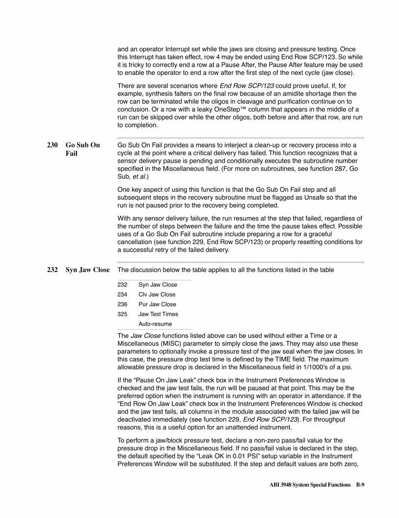
ABI 3948 System Special Functions B-9
and an operator Interrupt set while the jaws are closing and pressure testing. Once this Interrupt has taken effect, row 4 may be ended using End Row SCP/123. So while it is tricky to correctly end a row at a Pause After, the Pause After feature may be used to enable the operator to end a row after the first step of the next cycle (jaw close).
There are several scenarios where End Row SCP/123 could prove useful. If, for example, synthesis falters on the final row because of an amidite shortage then the row can be terminated while the oligos in cleavage and purification continue on to conclusion. Or a row with a leaky OneStep™ column that appears in the middle of a run can be skipped over while the other oligos, both before and after that row, are run to completion.
230 Go Sub On Fail
Go Sub On Fail provides a means to interject a clean-up or recovery process into a cycle at the point where a critical delivery has failed. This function recognizes that a sensor delivery pause is pending and conditionally executes the subroutine number specified in the Miscellaneous field. (For more on subroutines, see function 287, Go Sub, et al.)
One key aspect of using this function is that the Go Sub On Fail step and all subsequent steps in the recovery subroutine must be flagged as Unsafe so that the run is not paused prior to the recovery being completed.
With any sensor delivery failure, the run resumes at the step that failed, regardless of the number of steps between the failure and the time the pause takes effect. Possible uses of a Go Sub On Fail subroutine include preparing a row for a graceful cancellation (see function 229, End Row SCP/123) or properly resetting conditions for a successful retry of the failed delivery.
232 Syn Jaw Close The discussion below the table applies to all the functions listed in the table
The Jaw Close functions listed above can be used without either a Time or a Miscellaneous (MISC) parameter to simply close the jaws. They may also use these parameters to optionally invoke a pressure test of the jaw seal when the jaw closes. In this case, the pressure drop test time is defined by the TIME field. The maximum allowable pressure drop is declared in the Miscellaneous field in 1/1000's of a psi.
If the “Pause On Jaw Leak” check box in the Instrument Preferences Window is checked and the jaw test fails, the run will be paused at that point. This may be the preferred option when the instrument is running with an operator in attendance. If the “End Row On Jaw Leak” check box in the Instrument Preferences Window is checked and the jaw test fails, all columns in the module associated with the failed jaw will be deactivated immediately (see function 229, End Row SCP/123). For throughput reasons, this is a useful option for an unattended instrument.
To perform a jaw/block pressure test, declare a non-zero pass/fail value for the pressure drop in the Miscellaneous field. If no pass/fail value is declared in the step, the default specified by the “Leak OK in 0.01 PSI” setup variable in the Instrument Preferences Window will be substituted. If the step and default values are both zero,
232 Syn Jaw Close
234 Clv Jaw Close
236 Pur Jaw Close
325 Jaw Test Times
Auto-resume

B-10 ABI 3948 System Special Functions
no jaw/block pressure test will be performed. The “Man Cont Jaw Testing” check box in the Instrument Preferences window must be checked to enable jaw/block pressure testing based on default values when closing the jaws in manual control. Jaw testing can also be initiated in manual control by specifying the test parameters when executing the jaw close.
Jaw Test Times uses the TIME field to define the default pressure drop time for any jaw/block pressure test. The initial pressurization time in whole seconds (settling time) is defined in the Miscellaneous field. If this function is not used to define these times, a default of 30 seconds will be used for both. The times established by this function must be reinstated after a power failure or database reset.
The Instrument Preferences window contains the testing pressure in psi for jaw/block pressure tests performed within cycles and defines the terms under which the auto-resume feature will be enabled. The term “auto-resume” refers to the 3948's ability to wait for a period and then restart itself after being paused by a sensor delivery failure. The auto-resume feature is closely tied to the results of the jaw/block pressure tests and so it is discussed here.
For auto-resume to be enabled, three basic requirements must be met. The first requirement is for the operator to select the correct settings in the Instrument Preferences Window. The default settings accomplish this. Secondly, the system must be shown to be currently leak tight so that auto-resuming will not result in magnifying spillage due to a leak. Depending on the results of each individual jaw/block leak test, some active cycles may not be allowed to auto-resume at the same time that others would be. Finally, auto-resume is an automatic process designed for unattended operation: control is always surrendered to the operator if there is any manual intervention with the instrument while an auto-resume is pending.
To meet all three conditions, a number of factors must be in place:
� “Pause On Sensor Fail” must be checked in the Instrument Preferences Window so that sensor delivery pausing is enabled.
� “Auto-resume Minutes” in the Instrument Preferences Window must be set to some value greater than zero (15 minutes is the default).
� Jaw/block pressure testing must be in effect and the testing pressure must be done at the system maximum 12 psi as specified by the “Jaw Leak Test in PSI” setup variable in the Instrument Preferences Window. A value of 12 psi is the default for this setup variable.
� Jaw/block pressure testing must be performed with a minimum pressure drop time of 30 seconds. This is the default time provided for by the system but care must be used if this time is modified either within the jaw close step or by setting an alternate default using Jaw Test Times.
� Jaw/block testing must past the “Auto-res OK 0.01 PSI” test standard in the Instrument Preferences Window. This allows a maximum pressure drop of only 1.80 psi to pass compared to a maximum allowable drop of 5 psi for the “Leak OK in 0.01 PSI” preference value.
These setup variable default values are 1.30 and 2.00 psi, respectively (entered in 1/100's p.s.i. as 130 and 200). It is possible for the instrument to “pass” the jaw/block leak test and run chemistry while not passing a more stringent standard required to enable auto-resume.
� The instrument must be running automatically. Any intervention by an operator during an auto-resume wait period will cancel the auto-resume. Such operator
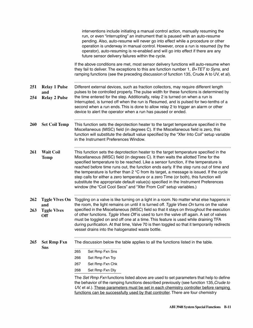
ABI 3948 System Special Functions B-11
interventions include initiating a manual control action, manually resuming the run, or even “interrupting” an instrument that is paused with an auto-resume pending. Also, auto-resume will never go into effect while a procedure or other operation is underway in manual control. However, once a run is resumed (by the operator), auto-resuming is re-enabled and will go into effect if there are any future sensor delivery failures within the cycle.
If the above conditions are met, most sensor delivery functions will auto-resume when they fail to deliver. The exceptions to this are function number 1, B+TET to Syns, and ramping functions (see the preceding discussion of function 135, Crude A to UV, et al).
251 Relay 1 Pulseand
254 Relay 2 Pulse
Different external devices, such as fraction collectors, may require different length pulses to be controlled properly. The pulse width for these functions is determined by the time entered for the step. Additionally, relay 2 is turned on when a run is Interrupted, is turned off when the run is Resumed, and is pulsed for two-tenths of a second when a run ends. This is done to allow relay 2 to trigger an alarm or other device to alert the operator when a run has paused or ended.
260 Set Coil Temp This function sets the deprotection heater to the target temperature specified in the Miscellaneous (MISC) field (in degrees C). If the Miscellaneous field is zero, this function will substitute the default value specified by the “Xfer Into Coil” setup variable in the Instrument Preferences Window.
261 Wait Coil Temp
This function sets the deprotection heater to the target temperature specified in the Miscellaneous (MISC) field (in degrees C). It then waits the allotted Time for the specified temperature to be reached. Like a sensor function, if the temperature is reached before time runs out, the function ends early. If the step runs out of time and the temperature is further than 2 °C from its target, a message is issued. If the cycle step calls for either a zero temperature or a zero Time (or both), this function will substitute the appropriate default value(s) specified in the Instrument Preferences window (the “Coil Cool Secs” and “Xfer From Coil” setup variables.)
262 Tggle Vlves Onand
263 Tggle VlvesOff
Toggling on a valve is like turning on a light in a room. No matter what else happens in the room, the light remains on until it is turned off. Tggle Vlves On turns on the valve specified in the Miscellaneous (MISC) field so that it stays on throughout the execution of other functions. Tggle Vlves Off is used to turn the valve off again. A set of valves must be toggled on and off one at a time. This feature is used while draining TFA during purification. At that time, Valve 70 is then toggled so that it temporarily redirects vessel drains into the halogenated waste bottle.
265 Set Rmp FxnSns
The discussion below the table applies to all the functions listed in the table.
The Set Rmp Fxn functions listed above are used to set parameters that help to define the behavior of the ramping functions described previously (see function 135,Crude to UV, et al.). These parameters must be set in each chemistry controller before ramping functions can be successfully used by that controller. There are four chemistry
265 Set Rmp Fxn Sns
266 Set Rmp Fxn Trp
267 Set Rmp Fxn Chk
268 Set Rmp Fxn Dly

B-12 ABI 3948 System Special Functions
controllers: synthesis, cleavage, purification, and manual control. The parameter values may be set differently for each controller. The parameter values are declared in the Miscellaneous (MISC) field of a Set Rmp Fxn function and set by executing the function within a given chemistry controller (i.e., within a cycle). Once set, these parameters will persist until changed.
When activated, sensors continuously sample for the presence of wetness every 12 milliseconds and record a series of “wet” and “dry” readings. Each sensor decides whether the flow path is wet or dry based on some number of the most recent readings taken and the proportion of those readings that is wet or dry. Except for ramping functions, these standards for wet/dry are fixed. The Set Rmp Fxn's allow the cycle developer to vary these values for ramping functions.
Set Rmp Fxn Sns defines how large a sampling of most recent readings will be evaluated to decide if the sensor flow path is wet or dry. This number cannot be larger than 10, the value that is assigned to most non-ramping functions.
Set Rmp Fxn Trp defines how many of the sample readings must be “wet” to trigger—or trip—the sensor. When dealing with cool, non-gaseous liquids it is reasonable to set this value high relative to the number of samples assessed (e.g., 9 “wets” out of a set of 10 readings). When dealing with hot, frothy ammonia coming out of the deprotection coils, a lower standard such as 5 “wets” out of 10 readings is reasonable.
The “Sns” and “Trp” values are built into all sensor functions but the ramping functions additionally verify a liquid slug once detected. Set Rmp Fxn Chk defines the number of “wets” required to verify—or check—the initial trigger and end function execution if verified. For a 9 out of 10 wet trigger, a 7 out of 10 verify is reasonable and a 5 out of 10 verify is fine for hot ammonia.
Set Rmp Fxn Dly defines the number of milliseconds to pause (delay) after the initial trigger before beginning to collect readings for the verification. To avoid losing too much sample past the sensor during verification, this delay should not be too long—50 milliseconds is typical.
If a ramping function does not verify within two and one-half seconds, it resets the sensor to look again for a new trip followed by a verify. Verification is especially useful during critical transfers because it allows the function to overlook any small slugs that might precede the principal slug. Without verification, the actual sample could be lost whenever a leading slug tricked a transfer into stopping too early.
It is technically possible for a ramping function to trip many times before verifying. In practice, a second trip is infrequent and a third trip has never been observed.

ABI 3948 System Special Functions B-13
269 Send Messageand
270 Comment
Send Message and Comment both send a message to be displayed in the instrument status window on the Mac. Which message to send is defined by the Miscellaneous (MISC) field. Messages contain instructions for the operator and comments contain informative descriptions. They are used in maintenance and test procedures such as bottle changes, sensor calibrations, and leak tests. Available messages and comments are listed below – some are reserved for possible future needs:
Messages List (for Send Message function 269):
“Place new 2g. amidites on synthesizer.” // Msg. 0
"Select 'resume' to continue.” // Msg. 1
“Auto-dilute procedure complete.” // Msg. 2
“Replace Amidites, Then Select Resume.” // Msg. 3
“Place empty columns in table pos. 1-9.” // Msg. 4
“ ” // Msg. 5
“Empty all bottles except Acetonitrile.” // Msg. 6
“Place empty columns in table pos. 1-3.” // Msg. 7
“Place empty columns in table pos. 4-6.” // Msg. 8
“Place empty columns in table pos. 7-9.” // Msg. 9
“Change reagent bottle now.” // Msg. 10
“Verify the needle is down in well 1.” // Msg. 11
“Verify the needle is down in well 8.” // Msg. 12
“Verify the needle is down in well 40.” // Msg. 13
“Verify the needle is down in well 48.” // Msg. 14
“Verify the needle is at left waste.” // Msg. 15
“Verify the needle is at right waste.” // Msg. 16
“Verify that all regs display 5 psi.” // Msg. 17
“System Message 18.” // Msg. 18
“System Message 19.” // Msg. 19
Comments List (or Comment function 270):
“ACN (Reg 4)” // comment 0
“Tet & Bases (Reg 9)”
“NMI, AC2O & I2 (Reg 8)”
“TCA + Acetic Acid (Reg 2)”
“Syn Col A (Reg 7)”
“Syn Col B (Reg 7)” // comment 5
“Syn Col C (Reg 7)”

B-14 ABI 3948 System Special Functions
“Syn VB's (Reg 7)”
“Clv VB's & Bot Depro (Reg 10)”
“Clv Cols (Reg 10)”
“Depro Coils (Reg 1)” // comment 10
“Depro Coil B (Reg 1)”
“Depro Coil C (Reg 1)”
“NH4OH + TEAA (Reg 5)”
“Pur VB's & Up Depro (Reg3)”
“Pur Col A (Reg 3)” // comment 15
“Pur Col B (Reg 3)”
“Pur Col C (Reg 3)”
“TEAA (Reg 5)”
“TFA + 20% Acn (Reg 6)”
“DI (Reg 5)” // comment 20
“20% ACN (Reg 6)”
“UV (Reg 3)”
“Vent Amidite v76 (Reg 9)”
“Vent NH4OH v74 (Reg 5)”
“Test(s) completed.” // comment 25
“Message #26”
“Message #27”
“Message #28”
“Message #29”
271 Begin of Cycleand
272 End of Cycle
These functions serve only to mark the beginning and ending steps of a cycle or procedure.
273 Begin Loopand
274 End Loop
These functions mark the beginning and ending boundaries of a block of steps that will be executed repeatedly. The number of times that the steps will be repeated, the loop counter, is defined in the Miscellaneous (MISC) field of the Begin Loop step.
The block of steps within a loop will always be executed at least once, even if the Begin Loop parameter is zero. This is because it is the End Loop function at the end of the block that decides whether the steps have been repeated enough times to drop out of the loop or not. If not, the loop counter is decrements by 1 and the loop is repeated, starting with the first step after Begin Loop. When all loops are done, the cycle continues with the step after the End Loop step. Cycles must always have a matching number of Begin and End Loop steps.

ABI 3948 System Special Functions B-15
Loops may be nested, that is, one or more loops may appear inside another loop. Loops may be nested up to ten levels deep. An example of loop nesting to two levels is outlined here:
Begin Loop 3 outer loop
[Steps to execute 3 times]
Begin Loop 5 inner loop
[Steps to execute 15 times] note: 15 = 3 x 5
End Loop end inner loop
End Loop end outer loop
When loops are nested, it is the loop countdown counter for the outermost loop that is displayed in the Chemistry Monitor window. For the above example, the counter displayed would be the one declared by the first Begin Loop step which would count down from the initial value of 3.
275 Start Here This function marks the initial cycle step for the first synthesis cycle only. Normally, a synthesis cycle begins with the coupling of a new base to the oligo, proceeds through capping and oxidation, and then detritylates in preparation for another base addition at the start of the next cycle. In the first synthesis cycle, the 3' base is already attached to the support so the appropriate point to begin this cycle is with the initial detritylation.
276 Exit DMT On This function executes only on the last synthesis cycle of any given column and it only affects sequences that are being synthesized “trityl on” (i.e., purified oligos or “trityl on” crudes). Its purpose is to prevent oligos from being detritylated on their final synthesis cycle when no further base additions are forthcoming.
The effect of this function is to deactivate the column(s) that are just concluding synthesis in time to avoid a final detritylation. Further, continuing synthesis on columns making longer oligos will have no effect on those columns that have already finished. Oligos being synthesized “trityl off” have their columns deactivated at Cycle End.

B-16 ABI 3948 System Special Functions
277 If Pur Col A The discussion below the table applies to all the functions listed in the table.
The functions listed above are all used to build a programming construct generally referred to as an if statement. The basic purpose of an if statement is to execute a series of steps only if a certain condition is true.
The minimal form of an if statement is:
If
steps to do if true
EndIf
continue on.
A more complex variation is:
If
steps to do if true
Else
steps to do if false
EndIf
continue on.
If statements may be nested to any number of levels (see function 273, Begin Loop) but only one End If is needed with many If's:
If
steps to do if true
If
steps to do if also true
EndIf
continue on.
If the test condition is not met (is false) then the cycle skips the steps between the If function and the Else or EndIf function, whichever occurs first, and continues executing from that point. If the test condition is true, then the steps immediately after the If function are executed and any steps between the Else step (if there is one) and the EndIf are skipped. The Else and EndIf functions act as markers in the cycle to tell the If functions what steps to skip.
The If functions in this particular group all involve the status of column activity. Most likely, these functions would be used only in purification cycles. The If Pur Col functions can be used to select certain cycle steps for execution only if the oligo for a given column is to be purified. Similarly, the If Crude Col functions can be used to select certain cycle steps for execution only if the column is handling a crude oligo.
Instead of operating based on the status of just one column, If Any Act Cols provides a means to conditionally execute steps for a group of columns involved with purifying
277 If Pur Col A to 279 If Pur Col C
280 Else
281 EndIf
291 If Any Act Cols
297 If Crude Col A to 299 If Crude Col C

ABI 3948 System Special Functions B-17
oligos. After using function 282, Select Pur Cols, only those columns that remain active will be affected by the steps between If Any Act Cols and EndIf.
282 Select PurCols
The discussion below the table applies to all the functions listed in the table.
The Select /Engage/Revive functions are all designed to change the status of which columns are active and which are not. Normally a column is active if it is processing an oligo, either crude or purified, and inactive if it is not. Column active status is initialized automatically at the beginning of each cycle for the set of oligos being processed during that cycle.
Select Pur Cols will deactivate any columns that are processing crude oligos and leave only those columns active that are processing purified oligos. Using this function in conjunction with If Any Act Cols provides a convenient means to restrict purification activities to just those columns that need them.
Engage All Cols ensures that all columns are active, even if they are not all currently processing oligos. One use for this feature is to guarantee that all of the coils are cleaned as needed. Otherwise, if a single oligo is being cleaved by the current cycle, only the coil for that oligo would get cleaned—even if the previous cycle had “dirtied” all three coils by filling them with oligos to be deprotected.
Revive Act Cols will restore to active status any column that was set up for synthesis but that has since been deactivated. This mechanism may be used to reactivate columns that were turned off because their syntheses had been concluded previously. When used in conjunction with If Cyc Greater, this function can enable the execution of the “end procedure” on all synthesizing columns during the last synthesis of the longest oligo in a set of three. This is useful for creating cycles to manage special additions at the 5´ end, i.e., extra washing after dye labelling or extra detritylation for certain modified aminos.
Revive Act Cols may also be used to reactivate columns that have been ended due to a jaw/block leak test failure or by the use of the End Row SCP/123 (see function number 229 above). By using this function in the purification cycle, oligos in the coils may be recovered even though the jaw/block leak test has failed.
Select Act Cols undoes the effects of the other three related functions by properly reselecting only normally active columns, i.e. just those columns actually processing oligos, regardless of type. If Select Pur Cols has turned off any columns processing crude oligos, this function will reactivate those columns. Similarly, columns will be deactivated if they are columns that have been reactivated by Revive Act Cols or columns without oligos that have been activated by Engage All Cols.
282 Select Pur Cols
283 Select Act Cols
300 Engage All Cols
319 Revive Act Cols

B-18 ABI 3948 System Special Functions
284 Clv Wants Depro
The discussion below the table applies to all the functions listed in the table.
These three functions are used by cleavage and purification cycles to arbitrate between the two systems regarding the shared ownership of the deprotection coils.
Pur Owns Depro is executed early in the purification cycle to declare that the purification system has control of the coils. Once the deprotected oligos are transferred out of the coils into the purification vessels, the purification cycle executes Clv Owns Depro to surrender control of the coils to the cleavage system.
The cleavage cycle is responsible for cleaning out any residue from previously deprotected oligos before transferring in the most recently cleaved oligos. A Clv Wants Depro step is placed in the cleavage cycle immediately before this cleaning begins. The cleavage cycle waits at this step as long as the purification system retains ownership of the coils. Control of the coils is eventually transferred to cleavage (Clv Owns Depro) after the purification cycle has removed the previous set of deprotected oligos from the coils. At this point, the cleavage cycle moves on to clean the coils, transfer in the current set of oligos, and start deprotection.
Since there is no purification cycle running during the first cleavage cycle, Clv Owns Depro is executed in the begin procedure to ensure that the cleavage system is in possession of the coils when the first set of oligos in a run is ready for deprotection.
287 Go Sub The discussion below the table applies to all the functions listed in the table.
The set of functions above is involved with subroutines. A subroutine is a set of steps that accomplishes a particular task, such as filling or draining a set of vessels, performing a detritylation, or cleaning a transfer path. A cycle or procedure may have many subroutines.
Subroutines are always placed at the end of the cycle, after a Goto End step. The Goto End step is a marker that says to ignore all of the steps in the subroutines that follow and jump directly to the Cycle End step. Effectively, the Goto End step is the last step of the main cycle.
The Sub Label function marks the beginning of a subroutine. The Miscellaneous (MISC) field in the Sub Label step uniquely identifies a specific subroutine. All of the subroutines within a given cycle or procedure must have different numbers. Subroutines are only recognized within their cycle so the same Sub Label may be applied to different subroutines within different cycles.
By using Go Sub, a subroutine may be “called” from anywhere in the main cycle to do its job. Calling a subroutine means that cycle execution jumps from the main cycle down to the first step of the subroutine and begins executing the steps following the
284 Clv Wants Depro
285 Pur Owns Depro
286 Clv Owns Depro
287 Go Sub
288 Return Sub
289 Sub Label
290 Goto End

ABI 3948 System Special Functions B-19
Sub Label. The Miscellaneous field in a Go Sub step identifies the corresponding Sub Label step to jump to. Subroutines may not be called from other subroutines.
Return Sub marks the end of a subroutine. The steps in between the Sub Label and Return Sub steps constitute the working body of the subroutine. When a Return Sub step is reached, execution jumps back up to the main cycle and resumes at the step following the Go Sub step that called the subroutine. Column activity status may be adjusted by Return Sub (see Go Sub A/B/C below).
Subroutines are useful when the work of the subroutine must be done a number of times in different places in a cycle. With subroutines, only one copy of the steps required to do a given job needs to be created. Cycles may be written with fewer steps because every time the same steps recur in a cycle they can be replaced by a single Go Sub call. Also, if a subroutine's process ever needs alteration, changes need only be made in just one place instead of in several locations.
291 If Any ActCols
See preceding discussion of function 277, If Pur Col A, et al.
292 Go Sub A to
294 Go Sub C
These functions, called conditional Go Sub's, are a variation of the standard Go Sub function with a Select function twist (see function 282, Select Pur Cols). Each of these functions executes a subroutine call to the Sub Label step with a matching Miscellaneous (MISC) field value. However, this set of Go Sub's will execute the subroutine call only if their corresponding column is active.
A second feature of conditional Go Sub's is that when the subroutine is called, any other active columns are deactivated for the duration of the subroutine's execution. When a conditional Go Sub call is used, the Return Sub function automatically restores column activity status to what it was when the subroutine call was made. This status may be all columns active, only purification columns active, etc. (see function 282, Select Pur Cols, et al.)
Conditional Go Sub's take advantage of the fact that almost all column delivery functions come in sets consisting of one parallel version of the function and three serial, column-specific versions (e.g., ACN to Syn Cols and ACN to Syn Col A, B, or C). When only one column is active, the parallel version of a function will behave exactly like the serial version for that active column. If a subroutine is written using parallel functions and then called conditionally, it will act like a subroutine written for one specific column.
Conditional subroutine calls may be used to help minimize the total number of cycle steps, simplify cycle updates, and maximize the uniformity of cycle execution across columns.

B-20 ABI 3948 System Special Functions
295 If First Cycle The discussion below the table applies to all the functions listed in the table.
This is another category of If functions which must be paired with an Endif as discussed above (see function 277, If Pur Col A). These functions are only valid in a synthesis cycle. They cause a block of steps to be conditionally executed or skipped over based on the number of the cycle currently executing.
The block of steps between If First Cycle and its corresponding Else or Endif step will only be executed if the current cycle in progress is the first cycle of synthesis. Similarly, the block of steps between If Last Cycle and its corresponding Else or Endif step will only be executed if the current cycle in progress is the last cycle of the longest oligo being synthesized in a given row. These functions are useful for creating “begin -” and “end procedures” for synthesis cycles which may be used for instrument housekeeping purposes or to implement special cycle variations. When implementing special 5´ monomer cycles, If Last Cycle will usually be used in conjunction with Revive Act Cols (see the preceding discussion of function 282, Select Pur Cols, et al).
The If Cyc Greater function enables the synthesis cycle to modify or adapt its activities as the oligo it creates gets longer. The Miscellaneous (MISC) field is used to define the cycle number at which synthesis will begin to execute additional steps. By nesting If Cyc Greater steps (see function 277, If Pur Col A), new activities may be gradually incorporated into the cycle as the oligo reaches new milestone lengths.
Having an adaptive cycle removes the requirement to have multiple cycles for different length oligos. It also allows the chemistry to perform optimally at each oligo length instead of attempting to strike a balance between the activity required during early cycles and that required later on. This capability facilitates minimizing cycle time and maximizing cycle performance.
297 If Crude Col Ato
299 If Crude Col C
See preceding discussion of function 277, If Pur Col A, et al.
300 Engage AllCols
See the preceding discussion of function 282, Select Pur Cols, et al.
316 If Cyc Greater See the preceding discussion of function 295, If First Cycle, et al.
317 Save Reg Presand
318 RestoreRegPres
Both of these functions use the Miscellaneous (MISC) field to declare the number of the regulator involved. Save Reg Pres will save the regulator pressure setting value of the specified regulator. Restore RegPres resets the pressure setpoint of the regulator to the value saved by Save Reg Pres. Regulator pressures may be saved and restored by subroutines that alter the regulator's pressure during their execution.
319 Revive ActCols
See the preceding discussion of function 282, Select Pur Cols, et al.
295 If First Cycle
296 If Last Cycle
316 If Cyc Greater
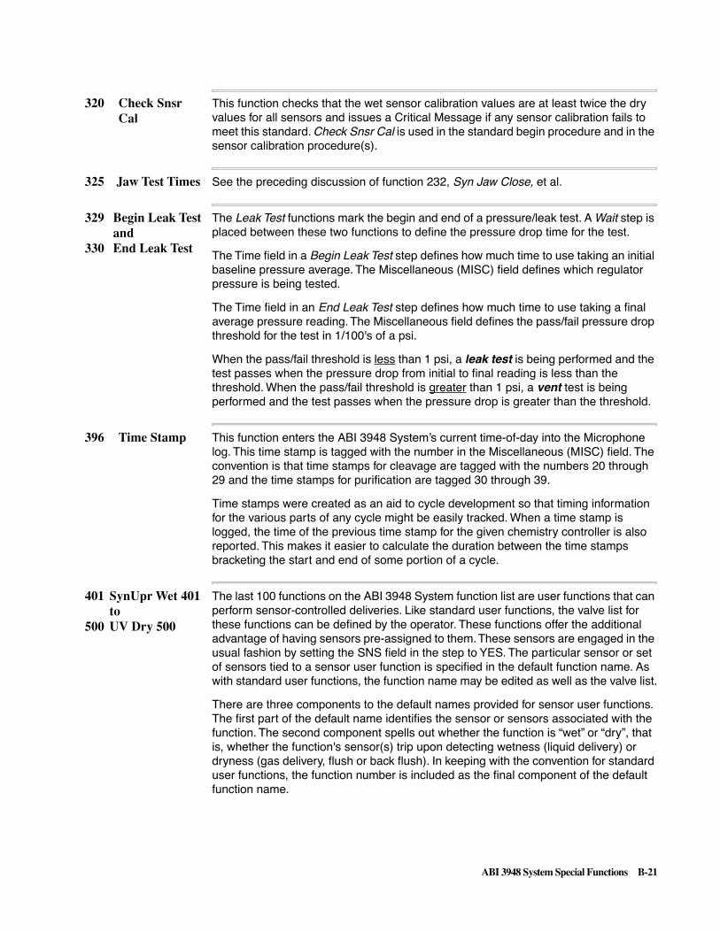
ABI 3948 System Special Functions B-21
320 Check SnsrCal
This function checks that the wet sensor calibration values are at least twice the dry values for all sensors and issues a Critical Message if any sensor calibration fails to meet this standard. Check Snsr Cal is used in the standard begin procedure and in the sensor calibration procedure(s).
325 Jaw Test Times See the preceding discussion of function 232, Syn Jaw Close, et al.
329 Begin Leak Testand
330 End Leak Test
The Leak Test functions mark the begin and end of a pressure/leak test. A Wait step is placed between these two functions to define the pressure drop time for the test.
The Time field in a Begin Leak Test step defines how much time to use taking an initial baseline pressure average. The Miscellaneous (MISC) field defines which regulator pressure is being tested.
The Time field in an End Leak Test step defines how much time to use taking a final average pressure reading. The Miscellaneous field defines the pass/fail pressure drop threshold for the test in 1/100's of a psi.
When the pass/fail threshold is less than 1 psi, a leak test is being performed and the test passes when the pressure drop from initial to final reading is less than the threshold. When the pass/fail threshold is greater than 1 psi, a vent test is being performed and the test passes when the pressure drop is greater than the threshold.
396 Time Stamp This function enters the ABI 3948 System’s current time-of-day into the Microphone log. This time stamp is tagged with the number in the Miscellaneous (MISC) field. The convention is that time stamps for cleavage are tagged with the numbers 20 through 29 and the time stamps for purification are tagged 30 through 39.
Time stamps were created as an aid to cycle development so that timing information for the various parts of any cycle might be easily tracked. When a time stamp is logged, the time of the previous time stamp for the given chemistry controller is also reported. This makes it easier to calculate the duration between the time stamps bracketing the start and end of some portion of a cycle.
401 SynUpr Wet 401to
500 UV Dry 500
The last 100 functions on the ABI 3948 System function list are user functions that can perform sensor-controlled deliveries. Like standard user functions, the valve list for these functions can be defined by the operator. These functions offer the additional advantage of having sensors pre-assigned to them. These sensors are engaged in the usual fashion by setting the SNS field in the step to YES. The particular sensor or set of sensors tied to a sensor user function is specified in the default function name. As with standard user functions, the function name may be edited as well as the valve list.
There are three components to the default names provided for sensor user functions. The first part of the default name identifies the sensor or sensors associated with the function. The second component spells out whether the function is “wet” or “dry”, that is, whether the function's sensor(s) trip upon detecting wetness (liquid delivery) or dryness (gas delivery, flush or back flush). In keeping with the convention for standard user functions, the function number is included as the final component of the default function name.

B-22 ABI 3948 System Special Functions
As with other sensor functions, parallel sensor user functions are always grouped on the function list together with their associated serial functions. So SynUpr Wet 401 is followed by SynUprWet A 402, SynUprWet B 403, and SynUprWet C 404.
Note Parallel sensor functions do not have valve lists of their own but use the valve lists of the associated serial sensor functions. Valve assignments must be made properly for all serial functions of a given type for the parallel sensor function to work or work properly. The
SynUpr, SynMan, and SynLow refer respectively to the upper synthesis sensors numbered 1 to 3, the synthesis manifold sensors numbered 22- to 24, and the lower synthesis sensors numbered 4 to 6. Sensors 7 to 9 are the Clv sensors, sensors 10 to 12 are the Coil sensors, and sensors 14 to 16 are the Pur sensors. Sensor 21 is the UV sensor. (See the Plumbing Diagram in Appendix E to verify which sensors are associated with which columns. In some instances, the column alphabetic order and sensor numeric order are reversed.)
As with other sensor functions, parallel sensor user functions are always grouped on the function list together with their associated serial functions. So SynUpr Wet 401 is followed by SynUprWet A 402, SynUprWet B 403, and SynUprWet C 404.
This grouping of sensor functions into sets is crucial to the operation of parallel functions. Parallel functions do not use their own valve lists to execute, they use the valve lists of their associated serial functions instead. In this way, parallel functions will turn on only the valves for active columns by merging together the valve list for each active column's associated serial function and excluding the valve lists of functions associated with inactive columns. When one column finishes its delivery before the others, its single set of valves is deactivated. Any other active columns' valves will remain on until their sensors trigger.
User definable functions operate according to the same scheme. In order to program the valve list for a parallel user function, the appropriate valve lists for each associated serial function must be entered. The value to also entering the complete, three-column valve set into the parallel function's valve list is one of documentation: the entire valve list may then be viewed under one function in Manual Control.

Cycles, Procedures, and System Messages C-1
Cycles, Procedures, and System Messages C
In This Appendix
Introduction This appendix contains listings of the standard synthesis, cleavage/deprotection, and purification cycles for use in understanding ABI 3948 System chemistry.
Topics Covered This appendix contains the following topics:
Topic See page
ABI 3948 System Chemistry C-2
Overview C-2
The Standard Synthesis Cycle C-2
Synthesis Cycle Summary C-2
Synthesis Cycle Listing C-4
The Standard Cleavage/Deprotection Cycle C-8
Cleavage/Deprotection Cycle Summary C-8
Cleavage/Deprotection Cycle Listing C-11
The Standard Purification Cycle C-17
Purification Cycle Summary C-17
Purification Cycle Listing C-22
Procedures C-31
General C-31
Edit Begin Procedure View C-31
Edit End Procedure View C-33
Edit Bottle Procedure View C-35
Miscellaneous Procedures C-36
System Messages C-37
Instrument Status and Message Indicators C-37
Types of Messages/Categories of Messages/Conventions C-37
Regular Reports Messages C-38
Critical Messages C-40
Microphone-only Messages C-40
Hierarchical Messages C-41
C

C-2 Cycles, Procedures, and System Messages
3948 Chemistry
Overview Chemistry Protocols
Chemistry in the ABI 3948 System is performed by assigning a protocol to each oligonucleotide to be produced. A protocol consists of three cycles to perform the three types of chemistry: synthesis, cleavage/deprotection, and purification. Each cycle is a series of functions which operate the valves and perform the other actions needed to produce an oligonucleotide.
Functions in Cycles
Functions are arranged in a particular order to create a cycle, which performs an operation. One Synthesis cycle, for example, contains all the functions necessary for one base addition. The functions in each standard cycle have optimized delivery times to ensure completion of each chemical reaction with minimal reagent consumption and minimal unwanted side reactions.
User Cycles
Besides the standard cycles, you can develop up to 34 additional cycles, 18 for synthesis, 8 for Cleavage/Deprotection, and 8 for Purification. Although the standard cycles cannot be changed or deleted, they can be copied into one of the user cycle locations and edited with the Cycle Editor to provide the basis for a new user cycle.
Synthesis Scale
The ABI 3948 System synthesizes at one scale only. Synthesis of a 25-mer typically yields 8.0-12 ODU of crude oligonucleotide, which when purified may equal 0.5 to 4 ODU.
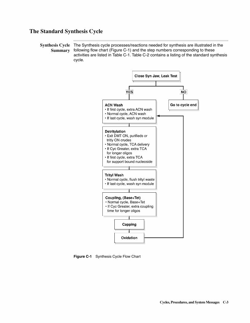
Cycles, Procedures, and System Messages C-3
The Standard Synthesis Cycle
Synthesis CycleSummary
The Synthesis cycle processes/reactions needed for synthesis are illustrated in the following flow chart (Figure C-1) and the step numbers corresponding to these activities are listed in Table C-1. Table C-2 contains a listing of the standard synthesis cycle.
Figure C-1 Synthesis Cycle Flow Chart

C-4 Cycles, Procedures, and System Messages
Table C-1 Summary of Synthesis Cycle
Step Range Description
47 - 52 Start Here, Leak Test
� Close synthesis jaw, begin leak test and check for pass or fail.
� If leak test passes, go to if first cycle.
� If leak test fails, go to cycle end.
53 - 67 ACN Wash
� If first cycle, give columns extra ACN wash.
� Normal column(s) ACN wash.
� Normal column(s) ACN wash
� If last cycle, synthesis module cleanup (Go Sub 3).
68 - 86 Detritylation
� Exit DMT On, for “purified or trityl on crude’s” only.
� This function executes only on the last synthesis cycle for each column.
� 7 loop of detritylation (Go Sub 3).
� If Cyc Greater, additional detritylation for longer oligos (Go Sub 2).
� If first cycle, additional detritylation for support bound nucleoside (Go Sub 2).
87 - 100- 44 Trityl Wash
� Wash and flush to trityl waste with ACN.
� If last cycle, execute synthesis module cleanup (Go Sub 3) in the case of “trityl off crudes”.
1 - 19 Begin of Cycle, Base+Tet (Coupling)
� Tetrazole and Base+Tet delivery.
� Coupling push/wait loop
� If Cyc Greater, extend coupling for longer oligos.
20 - 31 Capping
� Deliver capping reagents to manifold sensors.
� Capping push/wait loop
32 - 46 Oxidation
� Deliver Iodine to manifold sensors.
� Iodine push/wait loop

Cycles, Procedures, and System Messages C-5
Synthesis CycleListing
The annotated listing below is provided to aid you in understanding ABI 3948 System synthesis:
Table C-2 Standard Synthesis Cycle (v4.20)
STEP FUNCTION NUM TIME MISC SNS SAFE Comments
1) Begin of Cycle 271 0.0 0 Yes Yes Marks beginning of cycle
2) SynUprBlk Flush 105 2.0 0 No Yes Flush out upper synthesis block
3) TET to Syn Cols 48 5.0 0 Yes Yes Del. Ieading TET slug to lower sensors
4) B+ TET to Syns 1 0.0 0 Yes Yes Push TET to manifold sensors w/Base+Tet
5) ACN to SynWaste 47 2.0 0 No Yes Rinse and prime lower block w/ACN
6) ACN to Syn Cols 43 15.0 0 Yes Yes Push Base+TET to upper sensor w/ACN
7) Begin Loop 273 0.0 5 No Yes Begin coupling push/wait loop
8) Coupling Wait 26 8.0 0 No Yes Wait for Coupling (from B+TET table)
9) If Cyc Greater 316 0.0 60 No Yes iif after cycle/base 6O,
10) Wait 259 2.0 0 No Yes extend wait for coupling
11) If Cyc Greater 316 0.0 75 No Yes iif after cycle/base 75,
12) Wait 259 2.0 0 No Yes further extend wait for coupling
13) If Cyc Greater 316 0.0 90 No Yes iif after cycle/base 9O,
14) Wait 259 2.0 0 No Yes further extend wait for coupling
15) Endif 281 0.0 0 No Yes End of all "if cyc greater"
16) ACN to SynCol A 44 0.3 999 No Yes Push amidite to column A w/ACN or wait
17) ACN to SynCol B 45 0.3 999 No Yes Push amidite to column B w/ACN or wait
18) ACN to SynCol C 46 0.3 999 No Yes Push amidite to column C w/ACN or wait
19) End Loop 274 0.0 0 No Yes End coupling loop
20) SynLowBlk Flush 65 1.0 0 No Yes Flush out lower synthesis block
21) Go Sub 287 0.0 1 No Yes Flush columns/lines/blocks
22) CAP to Syn Cols 27 15.0 0 Yes Yes Deliver CAP to manifold sensors
23) ACN to SynWaste 47 1.5 0 No Yes Rinse and prime lower block w/ACN
24) ACN to Syn Cols 43 15.0 0 Yes Yes Push CAP to upper sensors w/ACN
25) Wait 259 1.0 0 No Yes Initial capping wait, all columns
26) Begin Loop 273 0.0 5 No Yes Begin capping push/wait loop
27) ACN to SynCol A 44 0.3 999 No Yes Push CAP to column A w/ACN or wait
28) ACN to SynCol B 45 0.3 999 No Yes Push CAP to column B w/ACN or wait
29) ACN to SynCol C 46 0.3 999 No Yes Push CAP to column C w/ACN or wait
30) Wait 259 1.4 0 No Yes Wait for capping, all columns
31) End Loop 274 0.0 0 No Yes End capping push/wait loop
32) ACN to SynWaste 47 1.0 0 No Yes Rinse lower block w/ACN
33) SynLowBlk Flush 65 1.5 0 No Yes Flush out lower synthesis block
34) Go Sub 287 0.0 1 No Yes Flush columns/lines/blocks
35) IODINE to Syns 33 15.0 0 Yes Yes Deliver iodine to manifold sensors
36) ACN to SynWaste 47 1.0 0 No Yes Rinse and prime lower block w/ACN
37) ACN to Syn Cols 43 15.0 0 Yes Yes Push iodine to upper sensors w/ACN
38) Wait 259 1.0 0 No Yes Initial oxidation wait, all columns

C-6 Cycles, Procedures, and System Messages
39) Begin Loop 273 0.0 5 No Yes Begin oxidation push/wait loop
40) ACN to SynCol A 44 0.3 999 No Yes Push iodine to column A w/ACN or wait
41) ACN to SynCol B 45 0.3 999 No Yes push iodine to column B w/ACN or wait
42) ACN to SynCol C 46 0.3 999 No Yes push iodine to column C w/ACN or wait
43) Wait 259 1.4 0 No Yes Wait for oxidation, all columns
44) End Loop 274 0.0 0 No Yes End oxidation push/wait loop
45) SynLowBlk Flush 65 1.5 0 No Yes Fiush out lower synthesis block
46) Go Sub 287 0.0 1 No Yes Flush columns/lines/blocks .
47) Start Here 275 0.0 0 No Yes First cycle begins here, detritylation
48) Syn Jaw Close 232 0.0 0 No Yes Close syn jaw, start syn module leak test
49) If Any Act Cols 291 0.0 0 No Yes Test for syn module leak test failure
50) Else 280 0.0 0 No Yes No action if passes
51) Goto End 290 0.0 0 No Yes Skip to end of cycle on failed leak test
52) Endif 281 0.0 0 No Yes End of syn module leak test
53) If First Cycle 295 0.0 0 No Yes First cycle only, lines may be wet
54) ACN to SynWaste 47 5.0 0 No Yes Rinse lower block w/ACN
55) SynLowBlk Flush 65 5.0 0 No Yes Flush out lower synthesis block
56) Flush Syn Col A 54 3.0 0 No Yes Flush column A
57) Flush Syn Col B 55 3.0 0 No Yes Flush column B
58) Flush Syn Col C 56 3.0 0 No Yes Flush column C
59) Go Sub 287 0.0 1 No Yes Flush columns/lines/blocks
60) Go Sub 287 0.0 4 No Yes Deliver ACN to upper sensors
61) Go Sub 287 0.0 1 No Yes Flush columns/lines/blocks
62) Endif 281 0.0 0 No Yes End first cycle line clean
63) Go Sub 287 0.0 4 No Yes Deliver ACN to upper sensors
64) Go Sub 287 0.0 1 No Yes Flush columns/lines/blocks
65) If Last Cycle 296 0.0 0 No Yes If last cycle, clean lines/blocks
66) Go Sub 287 0.0 3 No Yes Last cycle wash cola/lines/blocks
67) Endif 281 0.0 0 No Yes End if last cycle line/block clean
68) Exit DMT On 276 0.0 0 No Yes End here if trityl on
69) SynLowBlk Flush 65 1.0 0 No Yes Flush out lower synthesis block
70) TCA to Syn Cols 38 4.0 0 No No Start split delivery of TCAto columns
71) TCA to Syn Cols 38 15.0 0 Yes No Finish split delivery of TCA to sensors
72) Begin Loop 273 0.0 7 No No Begin detritylation loop
73) Go Sub 287 0.0 2 No No Serial TCA (detritylation) push
74) End Loop 274 0.0 0 No No End detritylation loop
75) If Cyc Greater 316 0.0 60 No No if after cycle/base 60, additional TCA push
76) Go Sub 287 0.0 2 No No Serial TCA (detritylation) push
77) If Cyc Greater 316 0.0 75 No No if after cycle/base 75, additional TCA push
78) Go Sub 287 0.0 2 No No Serial TCA (detritylation) push
79) If Cyc Greater 316 0.0 90 No No if after cycle/base 90, additional TCA push
Table C-2 Standard Synthesis Cycle (v4.20) (continued)
STEP FUNCTION NUM TIME MISC SNS SAFE Comments

Cycles, Procedures, and System Messages C-7
80) Go Sub 287 0.0 2 No No Serial TCA (detritylation) push
81) Endif 281 0.0 0 No No End of all "if cyc greater tests
82) If First Cycle 295 0.0 0 No No First cycle only, extra detritylation
83) Begin Loop 273 0.0 3 No No Begin first cycle oniv detritylation loop
84) Go Sub 287 0.0 2 No No Serial TCA (detritylation) push
85) End Loop 274 0.0 0 No No End first cycle only detritylation loop
86) Endif 281 0.0 0 No No End "if first cycle"
87) LowTrityl Flush 106 1.0 0 No No Flush lower block to halogenated wate
88) ACN to Trityl 108 2.0 0 No No Rinse lower block to halogenated wate
89) LowTrityl Flush 106 2.0 0 No No Flush lower block to halogenated wate
90) Waste to Trityl 109 0.0 999 No No Redirect v22 waste to v23 halo waste columns/lines/blocks
91) Go Sub 287 0.0 1 No No Flush columns/lines/blocks .
92) Go Sub 287 0.0 4 No No Deliver ACN to upper sensors
93) Go Sub 287 0.0 1 No No Flush columns/lines/blocks
94) Flush Syn Col A 54 2.0 0 No Yes Flush column A, extra dry step
95) Flush Syn Col B 55 2.0 0 No Yes Flush column B, extra dry step
96) Flush Syn Col C 56 2.0 0 No Yes Flush column C, extra dry step
97) Waste to Trityl 109 0.0 0 No Yes Restore v22 waste output
98) If Last Cycle 296 0.0 0 No Yes If last cycle, wash of cola/lines/blocks
99) Go Sub 287 0.0 3 No Yes Last cycle wash cola/lines/blocks
100) Endif 281 0.0 0 No Yes End if last cycle
101) Goto End 290 0.0 0 No Yes Skip subroutines to end of synthesis cycle
102) Sub Label 289 0.0 1 No No Flush columns/lines/blocks
103) SynLowBlk Flush 65 2.0 0 No No Flush out lower synthesis block
104) Flush Syn Cols 53 15.0 0 Yes No Flush lines thru columns to upper sensors
105) Flush Syn Cols 53 1.0 0 No No Short flush above upper sensors
106) Return Sub 288 0.0 0 No No End of Sub 1
107) Sub Label 289 0.0 2 No No Serial TCA (detritylation push
108) TCA to SynCol C 41 1.0 999 No No Push TCA to column C
109) TCA to SynCol B 40 1.0 999 No No Push TCA to column B
110) TCA to SynCol A 39 1.0 999 No No Push TCA to column A
111) Return Sub 288 0.0 0 No No End of Sub 2
112) Sub Label 289 0.0 3 No Yes Last cycle wash cola/lines/blocks
113) Revive Act Cols 319 0.0 0 No Yes Make all starting columns active again
114) LowTrityl Flush 106 10.0 0 No Yes Flush lower block to halogenated waste
115) SynLowBlk Flush 65 10.0 0 No Yes Flush out lower synthesis block
116) ACN to Syn Cols 43 2.0 0 No Yes Start split delivery of ACN
117) ACN to Syn Cols 43 15.0 0 Yes Yes Finish split delivery of ACN to sensors
118) Flush Syn Col A 54 20.0 0 No Yes Flush colum A to dryness
119) Flush Syn Col B 55 20.0 0 No Yes Flush colum B to dryness
Table C-2 Standard Synthesis Cycle (v4.20) (continued)
STEP FUNCTION NUM TIME MISC SNS SAFE Comments

C-8 Cycles, Procedures, and System Messages
120) Flush Syn Col C 56 20.0 0 No Yes Flush colum C to dryness
121) ACN to SynWaste 47 2.0 0 No Yes Rinse lower block w/ACN
122) SynLowBlk Flush 65 10.0 0 No Yes Flush out lower synthesis block
123) Select Act Cols 283 0.0 0 No Yes Switch off all previously completed columns
124) Return Sub 288 0.0 0 No Yes End of Sub3
125) Sub Label 289 0.0 4 No No Deliver ACN to upper sensors
126) ACN to Syn Cols 43 4.0 0 No No Start split delivery of ACN
127) ACN to Syn Cols 43 15.0 0 Yes No Finish split delivery of ACN to sensors
128) ACN to Syn Cols 43 0.5 0 No No Short ACN push past sensors
129) Return Sub 288 0.0 0 No No End of Sub 4
130) End of Cycle 272 0.0 0 Yes Yes Marks end of cycle and all sub routines
Table C-2 Standard Synthesis Cycle (v4.20) (continued)
STEP FUNCTION NUM TIME MISC SNS SAFE Comments

Cycles, Procedures, and System Messages C-9
The Standard Cleavage/Deprotection Cycle
Cleavage/Deprotection Cycle
Summary
The Cleavage/Deprotection cycle processes/reactions needed for oligo production are illustrated in the following flow chart (Figure C-2) and the step numbers corresponding to these activities are listed in Table C-3. Table C-4 contains a listing of the standard cleavage/deprotection cycle:
Figure C-2 Cleavage/Deprotection Cycle Flow Chart

C-10 Cycles, Procedures, and System Messages
Table C-3 Summary of Cleavage/Deprotection Cycle
Step Range Description
1 - 10 Test for Active Columns
� Test oligos that have failed synthesis module leak test (failed columns will not be active.
� If synthesis module failed leak test, then (a) wait for synthesis and purification modules to complete leak testing, (b) wait until the deprotection coils are free and (c) clean up the cleavage module plumbing (Go Sub 9).(Go to cycle end).
� If columns Active, then close the synthesis jaw.
11 - 17 Leak Test, Start Here if Columns are Active
� Close the cleavage jaw, begin leak test and check for pass or fail.
� If cleavage module failed, the (a) wait until the deprotection coils are free and (b) clean up the cleavage module plumbing (Go Sub 9). (Go to cycle end).
� If cleavage module passed leak test, then start normal cleavage cycle.
18 - 33 Cleaning of Cleavage Vessels, Prep for Crude Oligos
� Water wash and flush of lower cleavage block.
� Water wash, flush and drying of cleavage columns, vessels and lines.
34 - 59 Ammonia Cleave of Oligo from the Support
� Start Cleavage by delivering ammonia to the upper cleavage sensors. Rinse ammonia from the lower cleavage block. Wait while cleaving.
� Set Regulator 10 for the first push of fresh ammonia over the columns (Go Sub 1). Wait while cleaving.
� Begin cleavage loop, push fresh ammonia over the columns (Go Sub 1) and wait while cleaving.
60 Wait for Purification to Surrender the Deprotection Coils to Cleavage
� Cleavage wants the deprotection coils

Cycles, Procedures, and System Messages C-11
61 - 74 Prepare and Transfer Oligos from the Cleavage Vessels to the Deprotection Coils
� Set coil temperature for the transfer INTO the coils. Wash the transfer line, coils and cleavage blocks.
� Set the ramping function parameters.
� Gently consolidate sample into cleavage vessels.
� Ramping transfer into coils from cleavage vessels.
75 Start Deprotection Heater
� Start the clock for deprotection time (set in preferences) once the target temperatures reached.
76 - 93 Column Strip of Uncleaved Product
� Start column strip, deliver ammonia to upper cleavage sensors. Rinse ammonia from the lower cleavage block. Wait while stripping.
� Set regulator 10 for the first push of fresh ammonia over the columns (Go Sub 1). Wait while stripping.
� Begin column stripping loop, push fresh ammonia over the columns (Go Sub 1) and wait while stripping.
94 - 107 Wash, Drain and Dry Cleavage Module
� Drain an dry cleavage module.
� Water and ACN washes of columns, vessels and lines.
� Drain an dry cleavage module.
Table C-3 Summary of Cleavage/Deprotection Cycle (continued)
Step Range Description

C-12 Cycles, Procedures, and System Messages
Cleavage/Deprotection Cycle
Listing
The annotated listing below is provided to aid you in understanding ABI 3948 System cleavage and deprotection:
Table C-4 Standard Cleavage Cycle (v4.20)
STEP FUNCTION NUM TIME MISC SNS SAFE Comments
1) Begin of Cycle 271 0.0 0 No Yes Marks beginning of cycle
2) If Any Act Cols 291 0.0 0 No Yes Test for oligos that failed in synthesis
3) Else 280 0.0 0 No No If ok do nothing, else clean civ plumbing
4) Wait 259 60.0 0 No Yes Wait for syn/pur module leak testing
5) Wait 259 60.0 0 No No Wait for syn/pur module leak testing
6) Wait 259 60.0 0 No Yes Wait for syn/pur module leak testing
7) Clv Wants Depro 284 0.0 0 No Yes Wait until deprotection coils are free
8) Go Sub 287 0.0 9 No Yes Drain/wash/dry of coils & depro blocks
9) Goto End 290 0.0 0 No Yes Skip over subroutines to cycle end
10) Endif 281 0.0 0 No Yes To reach this step, columns are active
11) Clv Jaw Close 234 0.0 0 No Yes Close civ jaw, start civ module leak test
12) If Any Act Cols 291 0.0 0 No Yes Test for module leak test failure
13) Else 280 0.0 0 No Yes No action if test passes
14) Clv Wants Depro 284 0.0 0 No Yes Leak test failed, wait for depro coils
15) Go Sub 287 0.0 9 No Yes Drain/wash/dry of coils & blocks
16) Goto End 290 0.0 0 No Yes Skip over subroutines to cycle end
17) Endif 281 0.0 0 No Yes To reach this step, the leak test passed
18) Time Stamp 396 0.0 20 No Yes Record current time
19) Set Pres Reg 10 310 0.0 12 No Yes Set regulator 10 to 12 psi
20) Clv Blk Flush 144 5.0 0 No Yes Flush lower cleavage blocks, may be wet
21) H2O to ClvWaste 130 5.0 0 No Yes Wash lower cleavage blocks
22) Clv Blk Flush 144 5.0 0 No Yes Flush lower cleavane blocks
23) Begin Loop 273 0.0 2 No Yes Begin vessel/column/line water wash
24) Gas to Clv Cols 121 8.0 0 No Yes Dry vessels/columns/lines
25) Gas to ClvCol A 122 3.0 0 No Yes Dry vessel/column/line A
26) Gas to ClvCol B 123 3.0 0 No Yes Drv vessel/column/line B
27) Gas to ClvCol C 124 3.0 0 No Yes Dry vessel/column/line C
28) Go Sub 287 0.0 7 No Yes Delivery of water to sensor
29) Go Sub 287 0.0 6 No Yes Serial 5 psi gas bubble of vessel
30) Set Pres Reg 10 310 0.0 12 No Yes Set regulator 10 to 12 psi
31) Go Sub 287 0.0 4 No Yes Drain vessel/column/line
32) Go Sub 287 0.0 5 No Yes Dry vessels/columns/lines
33) End Loop 274 0.0 0 No Yes End vessel/column line wash
34) Time Stamp 396 0.0 21 No Yes Record current time
35) Go Sub 287 0.0 3 No Yes Deliver ammonia to start cleavage
36) Clv Blk Flush 144 10.0 0 No Yes Flush ammonia from lower civ blocks
37) Dep Xfer Rinse 151 5.0 0 No Yes Wash ammonia from lower civ blocks
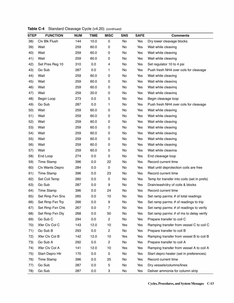
Cycles, Procedures, and System Messages C-13
38) Clv Blk Flush 144 10.0 0 No Yes Dry lower cleavage blocks
39) Wait 259 60.0 0 No Yes Wait while cleaving
40) Wait 259 60.0 0 No Yes Wait while cleaving
41) Wait 259 60.0 0 No Yes Wait while cleaving
42) Set Pres Reg 10 310 0.0 4 No Yes Set regulator 10 to 4 psi
43) Go Sub 287 0.0 1 No Yes Push fresh NH4 over cols for cleavage
44) Wait 259 60.0 0 No Yes Wait while cleaving
45) Wait 259 60.0 0 No Yes Wait while cleavinq
46) Wait 259 60.0 0 No Yes Wait while cleavinq
47) Wait 259 20.0 0 No Yes Wait while cleavinq
48) Begin Loop 273 0.0 5 No Yes Begin cleavage loop
49) Go Sub 287 0.0 1 No Yes Push fresh NH4 over cols for cleavage
50) Wait 259 60.0 0 No Yes Wait while cleaving
51) Wait 259 60.0 0 No Yes Wait while cleaving
52) Wait 259 60.0 0 No Yes Wait while cleaving
53) Wait 259 60.0 0 No Yes Wait while cleaving
54) Wait 259 60.0 0 No Yes Wait while cleaving
55) Wait 259 60.0 0 No Yes Wait while cleaving
56) Wait 259 60.0 0 No Yes Wait while cleaving
57) Wait 259 60.0 0 No Yes Wait while cleavina
58) End Loop 274 0.0 0 No Yes End cleavage loop
59) Time Stamp 396 0.0 22 No Yes Record current time
60) Clv Wants Depro 284 0.0 0 No Yes Wait until deprotection coils are free
61) Time Stamp 396 0.0 23 No Yes Record current time
62) Set Coil Temp 260 0.0 0 No Yes Temp for transfer into coils (set in prefs)
63) Go Sub 287 0.0 9 No Yes Drain/wash/dry of coils & blocks
64) Time Stamp 396 0.0 24 No Yes Record current time
65) Set Rmp Fxn Sns 265 0.0 10 No Yes Set ramp parms: # of total readings
66) Set Rmp Fxn Trp 266 0.0 9 No Yes Set ramp parms: # of readings to trip
67) Set Rmp Fxn Chk 267 0.0 7 No Yes Set ramp parms: # of readings to verify
68) Set Rmp Fxn Dly 268 0.0 50 No Yes Set ramp parms: # of ms to delay verify
69) Go Sub C 294 0.0 2 No Yes Prepare transfer to coil C
70) Xfer Clv Col C 143 12.0 10 Yes Yes Ramping transfer from vessel C to coil C
71) Go Sub B 293 0.0 2 No Yes Prepare transfer to coil B
72) Xfer Clv Col B 142 12.0 10 Yes Yes Ramping transfer from vessel B to coil B
73) Go Sub A 292 0.0 2 No Yes Prepare transfer to coil A
74) Xfer Clv Col A 141 12.0 10 Yes Yes Ramping transfer from vessel A to coil A
75) Start Depro Htr 170 0.0 0 No Yes Start depro heater (set in preferences)
76) Time Stamp 396 0.0 25 No Yes Record current time
77) Go Sub 287 0.0 5 No Yes Dry vessels/columns/lines
78) Go Sub 287 0.0 3 No Yes Deliver ammonia for column strip
Table C-4 Standard Cleavage Cycle (v4.20) (continued)
STEP FUNCTION NUM TIME MISC SNS SAFE Comments

C-14 Cycles, Procedures, and System Messages
79) Wait 259 30.0 0 No Yes Wait while stripping column
80) Wait 259 60.0 0 No Yes Wait while stripping column
81) Set Pres Reg 10 310 0.0 4 No Yes Set regulator 10 to 4 psi
82) Ammonia toWaste 115 1.0 0 No Yes Prime block with ammonia
83) Ammonia to ClvA 112 1.0 0 No Yes Deliver ammonia to column A
84) Ammonia to ClvB 113 1.0 0 No Yes Deliver ammonia to column B
85) Ammonia to ClvC 114 1.0 0 No Yes Deliver ammonia to column C
86) Clv Blk Flush 144 2.0 0 No Yes Flush ammonia from lower civ blocks
87) Wait 259 30.0 0 No Yes Wait while stripping column
88) Wait 259 60.0 0 No Yes Wait while stripping column
89) Begin Loop 273 0.0 6 No Yes Begin column strip loop
90) Go Sub 287 0.0 1 No Yes Gas push (for strip)
91) Wait 259 30.0 0 No Yes Wait while stripping
92) Wait 259 60.0 0 No Yes Wait while stripping
93) End Loop 274 0.0 0 No Yes End column strip loop
94) Go Sub 287 0.0 4 No Yes Drain & dry vessel/column/line
95) Go Sub 287 0.0 5 No Yes Dry vessels/columns/lines
96) Go Sub 287 0.0 7 No Yes Delivery of water to sensor
97) Go Sub 287 0.0 6 No Yes Serial 5 psi gas bubble of vessel
98) Go Sub 287 0.0 4 No Yes Drain vessel/column/line
99) Go Sub 287 0.0 5 No Yes Dry vessels/columns/lines
100) Go Sub 287 0.0 8 No Yes 2:1 water/ACN vessel wash
101) Go Sub 287 0.0 4 No Yes Drain & dry vessel/column/line
102) Go Sub 287 0.0 5 No Yes Dry vessels/columns/lines
103) Go Sub 287 0.0 8 No Yes 2:1 water/ACN vessel wash
104) Go Sub 287 0.0 4 No Yes Drain vessels/column/line
105) Go Sub 287 0.0 5 No Yes Dry vessels/columns/lines
106) Time Stamp 396 0.0 26 No Yes Record current time
107) Goto End 290 0.0 0 No Yes Skip over subroutines to cycle end
108) Sub Label 289 0.0 1 No Yes Gas push (for cleavage & strip)
109) Clv Blk Flush 144 1.0 0 No Yes Flush lower cleavage blocks
110) Press Line 138 2.0 0 No Yes Pressurize line to avoid-reverse flow
111) Gas to ClvCol A 122 0.6 0 No Yes Push of fresh NH4 over col A for strip
112) Clv Blk Flush 144 1.0 0 No Yes Flush lower cleavage blocks
113) Press Line 138 2.0 0 No Yes Pressurize line to avoid reverse flow
114) Gas to ClvCol B 123 0.6 0 No Yes Push of fresh NH4 over col B for strip
115) Clv Blk Flush 144 1.0 0 No Yes Flush lower cleavage blocks
116) Press Line 138 2.0 0 No Yes Pressurize line to avoid reverse flow
117) Gas to ClvCol C 124 0.6 0 No Yes Push of fresh NH4 over col C for strip
118) Return Sub 288 0.0 0 No Yes End of subroutine 1
119) Sub Label 289 0.0 2 No Yes Prepare transfer to coils AIB/C
Table C-4 Standard Cleavage Cycle (v4.20) (continued)
STEP FUNCTION NUM TIME MISC SNS SAFE Comments

Cycles, Procedures, and System Messages C-15
120) Set Pres Reg 10 310 0.0 12 No Yes Set regulator 10 to 12 psi
121) Dep Xfer Rinse 151 3.0 0 No Yes Water rinse for transfer line
122) Dep Xfer Flush 152 20.0 0 No Yes Flush transfer line
123) Set Pres Reg 1 301 0.0 12 No Yes Set regulator 1 to 12 psi
124) DepUprBlk Rinse 154 3.0 0 No Yes Water rinse for upper depro block
125) DepUprBlk Flush 221 5.0 0 No Yes Flush upper depro block
126) DepLowBlk Flush 153 2.0 0 No Yes Flush lower depro block
127) Set Pres Reg 10 310 0.0 5 No Yes Set regulator 10 to 5 psi
128) Dep Xfer Flush 152 4.0 0 No Yes Reduce regulator 10 pressure
129) Gas to Clv Cols 121 12.0 0 No Yes Consolidate sample into vessels
130) Set Pres Reg 10 310 0.0 4 No Yes Starting transfer pressure
131) Dep Xfer Flush 152 2.0 0 No Yes Reduce regulator 10 pressure
132) Return Sub 288 0.0 0 No Yes End of subroutine 2
133) Sub Label 289 0.0 3 No Yes Deliver ammonia for cleave/strip
134) Ammonia toWaste 115 1.0 0 No Yes Prime block w/ ammonia
135) Ammonia to Clvs 111 3.0 0 No Yes Start split delivery of NH4
136) Ammonia to Clvs 111 15.0 0 Yes Yes Finish split delivery of NH4 to sensors
137) Return Sub 288 0.0 0 No Yes End of subroutine 3
138) Sub Label 289 0.0 4 No Yes Drain vessel/column/line
139) Set Pres Reg 10 310 0.0 12 No Yes Set regulator 10 to 12 psi
140) Back Flush Clvs 131 6.0 0 No Yes Wet sensors for all active vessels
141) Back Flush Clvs 131 45.0 0 Yes Yes Drain all vessels until sensors read dry
142) Back Flsh Clv A 132 6.0 0 No Yes Complete drain of vessel A
143) Back Flsh Clv B 133 6.0 0 No Yes Complete drain of vessel B
144) Back Flsh Clv C 134 6.0 0 No Yes Complete drain of vessel C
145) Begin Loop 273 0.0 2 No Yes Begin vessel drain/dry loop
146) Gas to Clv Cols 121 1.0 0 No Yes Reverse drying
147) Back Flush Clvs 131 4.0 0 No Yes Backflush drying
148) End Loop 274 0.0 0 No Yes End vessel drain/dry loop
149) Return Sub 288 0.0 0 No Yes End of subroutine 4
150) Sub Label 289 0.0 5 No Yes Dry vessels/columns/lines
151) Set Pres Reg 10 310 0.0 12 No Yes Set regulator 10 to 12 psi
152) Begin Loop 273 0.0 2 No Yes Begin drain/dry loop
153) Back Flsh Clv A 132 5.5 0 No Yes Drain column A
154) Back Flsh Clv B 133 5.5 0 No Yes Drain column B
155) Back Flsh Clv C 134 5.5 0 No Yes Drain column C
156) End Loop 274 0.0 0 No Yes End drain/dry loop
157) Gas to Clv Cols 121 2.0 0 No Yes Reverse drying
158) Back Flush Clvs 131 8.0 0 No Yes Backflush drying
159) Return Sub 288 0.0 0 No Yes End of subroutine 5
160) Sub Label 289 0.0 6 No Yes Serial 5 psi gas bubble of vessel
Table C-4 Standard Cleavage Cycle (v4.20) (continued)
STEP FUNCTION NUM TIME MISC SNS SAFE Comments

C-16 Cycles, Procedures, and System Messages
161) Set Pres Reg 10 310 0.0 5 No Yes Set regulator 10 to 5 psi
162) Gas to ClvCol A 122 8.0 0 No Yes Bubble vessel A
163) Gas to ClvCol B 123 8.0 0 No Yes Bubble vessel B
164) Gas to ClvCol C 124 8.0 0 No Yes Bubble vessel C
165) Return Sub 288 0.0 0 No Yes End of subroutine 6
166) Sub Label 289 0.0 7 No Yes Delivery of water to sensor
167) H2O to ClvWaste 130 1.0 0 No Yes Prime lower cleavage blocks w/ water
168) H2O to Clv Cols 126 2.0 0 No Yes Start split delivery of water
169) H2O to Clv Cols 126 15.0 0 Yes Yes Finish split delivery of water to sensor
170) Return Sub 288 0.0 0 No Yes End of subroutine 7
171) Sub Label 289 0.0 8 No Yes 2:1 water/ACN vessel wash
172) Set Pres Reg 10 310 0.0 6 No Yes Set regulator 10 to 6 psi
173) ACN to Clv Cols 116 20.0 0 Yes Yes Deliver ACN to sensors
174) Gas to Clv Cols 121 15.0 0 Yes Yes Push ACN until sensors read dry
175) Gas to Clv Cols 121 3.0 0 No Yes Consolidate ACN into vessels
176) Set Pres Reg 10 310 0.0 8 No Yes Set regulator 10 to 8 psi
177) Begin Loop 273 0.0 2 No Yes Begin water delivery loop
178) H2O to Clv Cols 126 15.0 0 Yes Yes Deliver water to sensors
179) Gas to Clv Cols 121 15.0 0 Yes Yes Push water until sensors read dry
180) Gas to Clv Cols 121 3.0 0 No Yes Consolidate water into vessels
181) End Loop 274 0.0 0 No Yes End water delivery loop
182) Set Pres Reg 10 310 0.0 12 No Yes Set regulator 10 to 12 psi
183) Gas to Clv Cols 121 10.0 0 No Yes Bubble/wash of water/ACN in vessels
184) Return Sub 288 0.0 0 No Yes End of subroutine 8
185) Sub Label 289 0.0 9 No Yes Drain/wash/dry of coils & blocks
186) Engage All Cols 300 0.0 0 No Yes Force all columns to be active
187) Set Pres Reg 1 301 0.0 12 No Yes Set regulator 1 to 12 psi
188) Gas to Coil A 156 15.0 0 No Yes Drain coil A
189) Gas to Coil B 157 15.0 0 No Yes Drain coil B
190) Gas to Coil C 158 15.0 0 No Yes Drain coil C
191) H20 to Coil A 163 8.0 0 No Yes Wash coil A
192) H20 to Coil B 164 8.0 0 No Yes Wash coil B
193) H20 to Coil C 165 8.0 0 No Yes Wash coil C
194) Gas to Coil A 156 15.0 0 No Yes Dry coil A
195) Gas to Coil B 157 15.0 0 No Yes Dry coil B
196) Gas to Coil C 158 15.0 0 No Yes Dry coil C
197) DepUprBlk Rinse 154 3.0 0 No Yes Water rinse for upper depro block
198) DepUprBlk Flush 221 5.0 0 No Yes Flush upper depro block
199) Set Pres Reg 10 310 0.0 12 No Yes Set regulator 10 to 12 psi
200) H2O to ClvWaste 130 3.0 0 No Yes Wash lower cleavage blocks w/ water
201) Clv Blk Flush 144 5.0 0 No Yes Flush lower cleavage blocks
Table C-4 Standard Cleavage Cycle (v4.20) (continued)
STEP FUNCTION NUM TIME MISC SNS SAFE Comments

Cycles, Procedures, and System Messages C-17
202) Select Act Cols 283 0.0 0 No Yes Select only cols available for chemistry
203) Return Sub 288 0.0 0 No Yes End of subroutine 8
204) End of Cycle 272 0.0 0 No Yes Marks end of cycle and all subroutines
Table C-4 Standard Cleavage Cycle (v4.20) (continued)
STEP FUNCTION NUM TIME MISC SNS SAFE Comments

C-18 Cycles, Procedures, and System Messages
The Standard Purification Cycle
Purification CycleSummary
The Purification cycle processes/reactions needed for oligo production are illustrated in the following flow chart (Figure C-3) and the step numbers corresponding to these activities are listed in Table C-5. Table C-6 contains a listing of the standard purification cycle:
Figure C-3 Purification Cycle Flow Chart

Cycles, Procedures, and System Messages C-19
Table C-5 Summary of Purification Cycle
Step Range Description
1 - 16 Test for Active Columns
� Purification owns the deprotection coils.
� Test for oligos that have ailed leak test in synthesis or cleavage cycles.
� If synthesis or cleavage modules failed leak test, then (a) wait for Syn and Clv modules to complete leak testing, (b) advance the sample collector 3 times for the next set of oligos, (c) drop the coil temperature to the transfer IN setting f(x) 260 and (d) give the depro coils to the cleavage module. Go to Cycle end.
� If synthesis or cleavage modules passed leak test, then close the purification jaw.
17 - 18 Start Here if Columns Active, Leak Test
� Close the purification jaw, begin leak test and check for pass or fail.
19 - 50 Start Purification Cycle or Recover Sample in Coils
� If leak test passes, then go to start of purification cycle at step 51.
� If leak test fails, restore active columns that were originally set from synthesis and execute the recovery of crude oligos from the coils.
� Set ramping function parameters. Wait for deprotection of crude oligos to complete. Drop the coil temperature to the transfer out setting. Set the coils to the transfer in temperature for the next row of oligos.
� Crude A to UV. Clean the purification blocks, transfer line, UV cell and sample collector delivery line. Move the sample collector (SC) rack to the load (close) position for the next sample. Lower the SC needle. Execute the “crude to UV” ramping function and transfer the crude oligo into the SC tube.
� Crude C to UV. Clean the purification blocks, transfer line, UV cell and sample collector delivery line. Move the sample collector (SC) rack to the load (close) position for the next sample. Lower the SC needle Execute the “crude to UV” ramping function and transfer the crude oligo into the SC tube.
� Wash and dry purification blocks, transfer line, UV cell and SC delivery line. Advance the SC for the next sample and open SC (move to front).
� Give cleavage the depro coils and end recovery routine.
51 - 58 Start Here if Purification Passed Leak Test, Wash and Dry Purification Module
� Set regulator 3 to 12 psi. Flush and wash lower pur blocks. Drain and dry pur module. Wash vessels with 2:1 water/ACN. Drain and dry pur module
59 - 60 Test for Crude or Purified Oligos
� Activate only the columns to be purified.
� Check for the columns to be purified. If yes, then go to step 61. If no, then skip to step 105 “Select Act Cols”.

C-20 Cycles, Procedures, and System Messages
61 - 68 Pre TFA Scrub, ACN/Water Wash of Pur Module
� Two ACN (Go Sub 5) and water (Go Sub 4) washes of the purification module. Drain and dry (Go Sub3) of the purification module.
69 - 70 TFA Scrub of Columns to be Used for Purification
� The OneStep™ columns that are selected to be purified are scrubbed with 3% TFA (Go Sub 9) to remove any product that was not cleaved during the cleavage portion of the cleavage cycle.
71 - 85 Post TFA Scrub, ACN/Water Wash of Pur Module
� Two AN washes of Pur module (Go Sub 5). Split parallel delivery of ACN to Pur Cols and split serial delivery of Water to Pur Cols.
� Loop the split deliveries two times. Water wash of pur module (Go Sub 4). Drain and Dry pur module (Go Sub 3).
86 - 104 Column Prep for Oligos to be Purified
� Split parallel delivery of TEAA to pur sensors. Flush upper pur block. Serial push of TEAA over columns into the vessels. Serial backflush of TEAA from the vessels over the columns out to waste.
� Three loops of a serial backflush to drain and dry the columns. Clean lower; purification block (Go Sub 10).
105 Select All Columns for Transfer of Oligos from Coils into the Purification Vessels
106 -122 Transfer Oligos from the Deprotection Coils into the Purification Vessels
� Set ramping function parameters (Go Sub 11).
� Purification module waits for deprotection to complete.
� Drop the coil temp. to the transfer out temperature.
� Purification block and transfer line are washed before the coil to pur column transfer.
� The coil contents are transferred into the pur vessels in column order C, B, A. The pur block and transfer line are rinsed and dried after the ramping transfer.
123 - 124 Cleavage Owns Depro Coils
� The lower purification is rinsed and dried with water.
� Cleavage owns the deprotection coils.
125 - 126 Test for Crude or Purified Oligos
� Activate only the columns to be purified.
� Check for the columns to be purified. If yes, then go to step 127.
� If no, then skip to step 162 “Select Act Cols”.
127 - 138 Sample Neutralization Loop
� Consolidate the crude sample in the vessels and dry the purification sensors. Flush lower pur block.
� Two parallel sensored deliveries of Acetic Acid to the columns.
Table C-5 Summary of Purification Cycle (continued)
Step Range Description
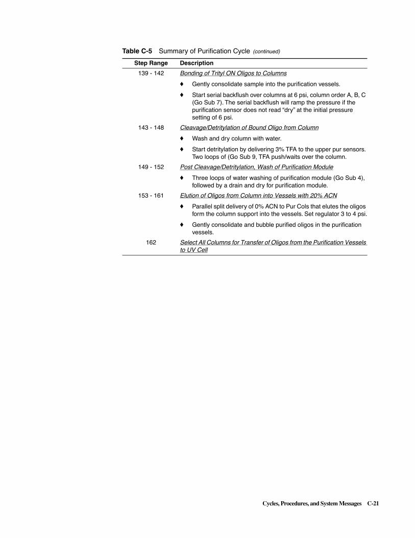
Cycles, Procedures, and System Messages C-21
139 - 142 Bonding of Trityl ON Oligos to Columns
� Gently consolidate sample into the purification vessels.
� Start serial backflush over columns at 6 psi, column order A, B, C (Go Sub 7). The serial backflush will ramp the pressure if the purification sensor does not read “dry” at the initial pressure setting of 6 psi.
143 - 148 Cleavage/Detritylation of Bound Oligo from Column
� Wash and dry column with water.
� Start detritylation by delivering 3% TFA to the upper pur sensors. Two loops of (Go Sub 9, TFA push/waits over the column.
149 - 152 Post Cleavage/Detritylation, Wash of Purification Module
� Three loops of water washing of purification module (Go Sub 4), followed by a drain and dry for purification module.
153 - 161 Elution of Oligos from Column into Vessels with 20% ACN
� Parallel split delivery of 0% ACN to Pur Cols that elutes the oligos form the column support into the vessels. Set regulator 3 to 4 psi.
� Gently consolidate and bubble purified oligos in the purification vessels.
162 Select All Columns for Transfer of Oligos from the Purification Vessels to UV Cell
Table C-5 Summary of Purification Cycle (continued)
Step Range Description

C-22 Cycles, Procedures, and System Messages
163 - 191 UV Quantitation and Sample Collection
Position A:
� Take UV baseline reading (Go Sub 1).
� Wash the UV cell and SC delivery line (Go Sub 12).
� Advance SC to the back (closed position) for next sample, lower SC needle into tube.
� Consolidate the sample into the vessel. Ramping sensored transfer of oligo, crude or purified, into the UV cell.
� Deliver ACN/water into the pur vessel (Go Sub 14).
� Quantitate oligo and deliver into SC vial (Go Sub 15).
Position B:
� Take UV baseline reading (Go Sub 1).
� Wash the UV cell and SC delivery line (Go Sub 12).
� Advance SC to the next position and lower the SC needle into the collection vial.
� Consolidate the sample into the vessel. Ramping sensored transfer of oligo, crude or purified, into the UV ell.
� Deliver ACN/water into the pur vessel (Go Sub 14).
� Quantitate oligo and deliver into SC vial (Go Sub 16).
Position C:
� Take UV baseline reading (Go Sub 1).
� Wash the UV cell and SC delivery line (Go Sub 12).
� Advance SC to the next position and lower the SC needle into the collection vial.
� Consolidate the sample into the vessel. Ramping sensored transfer of oligo, crude or purified, into the UV ell.
� Deliver ACN/water into the pur vessel (Go Sub 14).
� Quantitate oligo and deliver into SC vial (Go Sub 17). Wash UC cell and SC delivery line.
� Advance SC to the next position and move the SC to the front (open position).
192 - 199 Post Cycle, Purification Module Wash
� Push ACN/water into the purification vessels until the sensors are dry.
� Wash vessel by bubbling contents. Drain and dry pur module.
� 2:1 water/AN wash of pur vessels (Go Sub 8). Drain and dry purification module (Go Sub 3).
Table C-5 Summary of Purification Cycle (continued)
Step Range Description
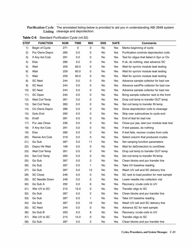
Cycles, Procedures, and System Messages C-23
Purification CycleListing
The annotated listing below is provided to aid you in understanding ABI 3948 system cleavage and deprotection:
Table C-6 Standard Purification Cycle (v4.52)
STEP FUNCTION NUM TIME MIS SNS SAFE Comments
1) Begin of Cycle 271 0 0 No Yes Marks beginning of cycle
2) Pur Owns Depro 285 0.0 0 No Yes Purification controls deprotection coils
3) If Any Act Cols 291 0.0 0 No Yes Test for oligos that failed in Syn or Clv
4) Else 280 0.0 0 No Yes If ok, do nothing, else advance SC
5) Wait 259 60.0 0 No Yes Wait for syn/civ module leak testing
6) Wait 259 60.0 0 No Yes Wait for syn/civ module leak testing
7) Wait 259 60.0 0 No Yes Wait for syn/civ module leak testing
8) SC Next 244 0.0 0 No Yes Advance sample collector for bad row
9) SC Next 244 0.0 0 No Yes Advance samPIe collector for bad row
10) SC Next 244 0.0 0 No Yes Advance sample collector for bad row
11) SC Open 245 0.0 0 No Yes Bring sample collector rack to the front
12) Wait Coil Temp 261 0.0 0 No Yes Drop coil temp to transfer OUT temp
13) Set Coil Temp 260 0.0 0 No Yes Set coil temp to transfer IN temp
14) Clv Owns Depro 286 0.0 0 No Yes Gives deprotection coils to cleavage
15) Goto End 290 0.0 0 No Yes Skip over subroutines to cycle end
16) Endif 281 0.0 0 No Yes End of test for bad row
17) Pur Jaw Close 236 0.0 0 No Yes CIose pur jaw, start pur module leak test
18) If Any Act Cols 291 0.0 0 No Yes If test passes, do nothing
19) Else 280 0.0 0 No Yes If test fails, recover crudes from coils
20) Revive Act Cols 319 0.0 0 No Yes Select column that produced crudes
21) Go Sub 287 0.0 11 No Yes Set ramping function parameters
22) Depro Htr Wait 169 0.0 0 No Yes Wait for deDrotection to comDIete
23) Wait Coil Temp 261 0.0 0 No Yes Drop coil temp to transfer OUT temp
24) Set Coil Temp 260 0.0 0 No Yes Set coil temp to transfer IN temp
25) Go Sub 287 0.0 2 No Yes CIean blocks and pur transfer line
26) Go Sub 287 0.0 1 No Yes Take UV baseline reading
27) Go Sub 287 0.0 12 No Yes Wash UV cell and SC delivery line
28) SC Close 246 0.0 0 No Yes SC rack to load position for next sample
29) SC Needle Down 248 0.0 0 No Yes Lower needle into collection vial
30) Go Sub A 292 0.0 6 No Yes Recovery: crude coils to UV
31) Xfer UV to SC 215 15.0 0 No Yes Transfer oligo to SC
32) Go Sub 287 0.0 2 No Yes CIean blocks and pur transfer line
33) Go Sub 287 0.0 1 No Yes Take UV baseline reading
34) Go Sub 287 0.0 12 No Yes Wash UV cell and SC delivery line
35) SC Next 244 0.0 0 No Yes Advance SC for next sample
36) Go Sub B 293 0.0 6 No Yes Recovery: crude coils to UV
37) Xfer UV to SC 215 15.0 0 No Yes Transfer oligo to SC
38) Go Sub 287 0.0 2 No Yes CIean blocks and pur transfer line

C-24 Cycles, Procedures, and System Messages
39) Go Sub 287 0.0 1 No Yes Take UV baseline reading
40) Go Sub 287 0.0 12 No Yes Wash UV cell and SC delivery line
41) SC Next 244 0.0 0 No Yes Advance SC for next sample
42) Go Sub C 294 0.0 6 No Yes Recovery: crude coils to UV
43) Xfer UV to SC 215 15.0 0 No Yes Transfer oligo to SC
44) Go Sub 287 0.0 2 No Yes CIean blocks and our transfer line
45) Go Sub 287 0.0 12 No Yes Wash UV cell and SC delivery line
46) SC Next 244 0.0 0 No Yes Advance SC for next sample
47) SC Open 245 0.0 0 No Yes SC rack to front
48) Clv Owns Depro 286 0.0 0 No Yes Cleavage owns the deprotection coils
49) Goto End 290 0.0 0 No Yes End of recovery of crudes routine
50) Endif 281 0.0 0 No Yes To reach here, leak test passed
51) Time Stamp 396 0.0 30 No Yes Time stamp
52) Set Pres Reg 3 303 0.0 12 No Yes Set regulator 3 to 12 psi
53) PurLowBlk Flush 218 5.0 0 No Yes Flush lower pur block, may be wet
54) ACN to PurWaste 177 5.0 0 No Yes ACN rinse of lower pur block
55) PurLowBlk Flush 218 5.0 0 No Yes Flush lower pur block
56) Go Sub 287 0.0 3 No Yes Drain & dry vessels/columns/lines
57) Go Sub 287 0.0 8 No Yes 2:1 water/ACN vessel wash
58) Go Sub 287 0.0 3 No Yes Drain & dry,vessels/columns/lines
59) Select Pur Cols 282 0.0 0 No Yes Activate only the columns to be purified
60) If Any Act Cols 291 0.0 0 No Yes Check here for any columns to be purified
61) Go Sub 287 0.0 5 No Yes ACN wash & bubble
62) Go Sub 287 0.0 3 No Yes Drain & dry vessels/columns/lines
63) Go Sub 287 0.0 5 No Yes ACN wash & bubble
64) Go Sub 287 0.0 3 No Yes Drain & dry vessels/columns/lines
65) Go Sub 287 0.0 4 No Yes Water wash & bubble
66) Go Sub 287 0.0 3 No Yes Drain & dry vessels/columns/lines
67) Go Sub 287 0.0 4 No Yes Water wash & bubble
68) Go Sub 287 0.0 3 No Yes Drain & dry vessels/columns/lines
69) Go Sub 287 0.0 9 No Yes Deliver TFA Scrub and drain
70) Go Sub 287 0.0 9 No Yes Deliver TFA Scrub and drain
71) Go Sub 287 0.0 5 No Yes ACN wash & bubble
72) Go Sub 287 0.0 3 No Yes Drain & dry vessels/columns/lines
73) Go Sub 287 0.0 5 No Yes ACN wash & bubble
74) Go Sub 287 0.0 3 No Yes Drain & dry vessels/columns/lines
75) Begin Loop 273 0.0 2 No Yes Begin ACN/water wash loop
76) ACN to Pur Cols 173 2.2 0 No Yes Start split delivery of ACN
77) ACN to Pur Cols 173 15.0 0 Yes Yes Finish split delivery of ACN to sensor
78) H2O to PurCol A 184 5.0 0 No Yes Water delivery to vessel A
79) H2O to PurCol B 185 5.0 0 No Yes Water delivery to vessel B
Table C-6 Standard Purification Cycle (v4.52) (continued)
STEP FUNCTION NUM TIME MIS SNS SAFE Comments

Cycles, Procedures, and System Messages C-25
80) H2O to PurCol C 186 5.0 0 No Yes Water delivery to vessel C
81) Gas to Pur Cols 203 15.0 0 No Yes Consolidate ACN/water into vessels
82) Go Sub 287 0.0 3 No Yes Drain & dry vessels/columns/lines
83) End Loop 274 0.0 0 No Yes End ACN/water wash loop
84) Go Sub 287 0.0 4 No Yes Water wash & bubble
85) Go Sub 287 0.0 3 No Yes Drain & dry vessels/columns/lines
86) Set Pres Reg 3 303 0.0 9 No Yes Set regulator 3 to 9 psi
87) TEAA to Waste 182 5.0 0 No Yes Prime block w/ TEAA
88) TEAA to PurCols 178 25.0 0 No Yes Start split delivery of TEAA
89) TEAA to PurCols 178 45.0 0 Yes Yes Finish split delivery of TEAA to sensors
90) PurUprBlk Flush 219 2.0 0 No Yes Flush upper pur block
91) Gas to PurCol A 204 10.0 0 No Yes Push TEAA over column into vessel A
92) Gas to PurCol B 205 10.0 0 No Yes Push TEAA over column into vessel B
93) Gas to PurCol C 206 10.0 0 No Yes Push TEAA over column into vessel C
94) Set Pres Reg 3 303 0.0 12 No Yes Set regulator 3 to 12 psi
95) Back Flsh Pur A 208 20.0 0 No Yes Drain TEAA from vessel A
96) Back Flsh Pur B 209 20.0 0 No Yes Drain TEAA from vessel B
97) Back Flsh Pur C 210 20.0 0 No Yes Drain TEAA from vessel C
98) Begin Loop 273 0.0 3 No Yes Begin TEAA drain/dry loop
99) Back Flsh Pur A 208 10.0 0 No Yes Drain TEAA from vessel A
100) Back Flsh Pur B 209 10.0 0 No Yes Drain TEAA from vessel B
101) Back Flsh Pur C 210 10.0 0 No Yes Drain TEAA from vessel C
102) End Loop 274 0.0 0 No Yes End TEAA drain/dry loop
103) Go Sub 287 0.0 10 No Yes Clean lower purification block
104) Endif 281 0.0 0 No Yes End of purification column prep
105) Select Act Cols 283 0.0 0 No Yes Select crude and purified columns
106) Go Sub C 294 0.0 2 No Yes Clean blocks and pur transfer line
107) Go Sub 287 0.0 11 No Yes Set ramping function parameters
108) Time Stamp 396 0.0 31 No Yes Time stamp
109) Depro Htr Wait 169 0.0 0 No Yes Wait for deprotection to complete
110) Time Stamp 396 0.0 32 No Yes Time stamp
111) Wait Coil Temp 261 0.0 0 No Yes Drop coil temp to transfer OUT temp
112) Set Coil Temp 260 0.0 0 No Yes Set coil temp to transfer IN temp
113) Time Stamp 396 0.0 33 No Yes Time stamp
114) Xfer Coil C 168 12.0 1 Yes No Ramping transfer from coil C to pur sensor
115) Xfer Coil C 168 20.0 0 No No Push sample from sensor to vessel
116) Go Sub B 293 0.0 2 No Yes Clean blocks and pur transfer line
117) Xfer Coil B 167 12.0 1 Yes No Ramping transfer from coil B to pur sensor
118) Xfer Coil B 167 20.0 0 No No Push sample from sensor to vessel
119) Go Sub A 292 0.0 2 No Yes Clean blocks and pur transfer line
120) Xfer Coil A 166 12.0 1 Yes No Ramping transfer from coil A to pur sensor
Table C-6 Standard Purification Cycle (v4.52) (continued)
STEP FUNCTION NUM TIME MIS SNS SAFE Comments

C-26 Cycles, Procedures, and System Messages
121) Xfer Coil A 166 20.0 0 No No Push sample from sensor to vessel
122) Time Stamp 396 0.0 34 No Yes Time stamp
123) Clv Owns Depro 286 0.0 0 No Yes Cleavage owns the depro coils
124) Go Sub 287 0.0 10 No Yes Clean lower purification block
125) Select Pur Cols 282 0.0 0 No Yes Select only the purified oligos
126) If Any Act Cols 291 0.0 0 No Yes Check if there are any oligos to purify
127) Set Pres Reg 3 303 0.0 9 No Yes Set regulator 3 to 9 psi
128) Gas to Pur Cols 203 60.0 0 No Yes Extra drying of purification sensors
129) Set Pres Reg 3 303 0.0 5 No Yes Set regulator 3 to 5 psi
130) PurLowBlk Flush 218 2.0 0 No Yes Fiush lower pur block
131) Begin Loop 273 0.0 2 No Yes Begin neutralization loop
132) AcAcid to Waste 202 2.0 0 No Yes Prime block with acetic acid
133) AcAcid to Purs 198 3.0 0 No Yes Start split delivery of acetic acid
134) AcAcid to Purs 198 30.0 0 Yes Yes Finish split delivery of acetic acid to sensor
135) Gas to Pur Cols 203 25.0 0 No Yes Mix samples in vessels and dry sensors
136) ACN to PurWaste 177 2.0 0 No Yes ACN rinse of lower pur block
137) PurLowBlk Flush 218 5.0 0 No Yes Flush lower pur block
138) End Loop 274 0.0 0 No Yes End neutralization loop
139) Gas to Pur Cols 203 15.0 0 No Yes Consolidate samples in vessels
140) Go Sub A 292 0.0 7 No Yes Bind oligo to column A
141) Go Sub B 293 0.0 7 No Yes Bind oligo to column B
142) Go Sub C 294 0.0 7 No Yes Bind oligo to column C
143) Go Sub 287 0.0 4 No No No Water wash & bubble
144) Go Sub 287 0.0 3 No Yes Drain & dry vessels/columns/lines
145) Go Sub 287 0.0 4 No Yes Water wash & bubble
146) Go Sub 287 0.0 3 No Yes Drain & dry vessels/columns/lines
147) Go Sub 287 0.0 9 No Yes Deliver TFA Detritylation
148) Go Sub 287 0.0 9 No Yes Deliver TFA Detritylation
149) Begin Loop 273 0.0 3 No No Begin water line/column/vessel wash loop
150) Go Sub 287 0.0 4 No No Water wash & bubble
151) Go Sub 287 0.0 3 No Yes Drain & dry vessels/columns/lines
152) End Loop 274 0.0 0 No No End water Erie/column/vessels wash loop
153) 20%ACN to Waste 197 4.0 0 No Yes Prime lower pur block w/ 20% ACN
154) 20%ACN to Purs 193 6.0 0 No Yes Start split delivery of 20% ACN
155) 20%ACN to Purs 193 15.0 0 Yes Yes Finish split deiiverv of 20% ACN, sensor
156) Go Sub 287 0.0 10 No Yes Clean lower purification block
157) Set Pres Reg 3 303 0.0 4 No Yes Set regulator 3 to 4 psi for elusion
158) PurLowBlk Flush 218 2.0 0 No Yes Flush lower pur block
159) Gas to Pur Cols 203 10.0 0 No Yes Elution: push 20% ACN to vessels
160) Endif 281 0.0 0 No Yes End of purification
161) Time Stamp 396 0.0 35 No Yes Time stamp
Table C-6 Standard Purification Cycle (v4.52) (continued)
STEP FUNCTION NUM TIME MIS SNS SAFE Comments

Cycles, Procedures, and System Messages C-27
162) Select Act Cols 283 0.0 0 No Yes Select all crudes and purifieds
163) Go Sub A 292 0.0 1 No Yes Take UV baseline reading
164) Go Sub A 292 0.0 12 No Yes Wash UV cell and SC delivery line
165) SC Close 246 0.0 0 No Yes SC rack to back for next sample
166) SC Needle Down 248 0.0 0 No Yes Lower needle into collection vial
167) Gas to PurCol A 204 7.0 0 No Yes Consolidate sample into vessel A
168) Pur A to UV 211 10.0 3 Yes Yes Ramping delivery of A to UV sensor
169) Pur A to UV 211 20.0 0 No Yes Finish delivery of A to UV cell
170) Go Sub A 292 0.0 14 No Yes Deliver ACN/water to vessels
171) Go Sub A 292 0.0 15 No Yes Quantitate & collect for sample A
172) Go Sub B 293 0.0 1 No Yes Take UV baseline reading
173) Go Sub B 293 0.0 12 No Yes Wash UV cell and SC delivery line
174) SC Next 244 0.0 0 No Yes Advance SC for next sample
175) Gas to PurCol B 205 7.0 0 No Yes Consolidate sample into vessel B
176) Pur B to UV 212 10.0 3 Yes Yes Ramping delivery of B to UV sensor
177) Pur B to UV 212 20.0 0 No Yes Finish delivery of B to UV cell
178) Go Sub B 293 0.0 14 No Yes Deliver ACN/water to vessels
179) Go Sub B 293 0.0 16 No Yes Quantitate & collect for sample B
180) Go Sub C 294 0.0 1 No Yes UV baseline reading
181) Go Sub C 294 0.0 12 No Yes Wash UV cell and SC delivery line
182) SC Next 244 0.0 0 No Yes Advance SC for next sample
183) Gas to PurCol C 206 7.0 0 No Yes Consolidate sample into vessel C
184) Pur C to UV 213 10.0 3 Yes Yes Ramping delivery of C to UV sensor
185) Pur C to UV 213 20.0 0 No Yes Finish delivery of C to UV cell
186) Go Sub C 294 0.0 14 No Yes Deliver ACN/water to vessels
187) Go Sub C 294 0.0 17 No Yes Quantitate & collect for sample C
188) Go Sub 287 0.0 12 No Yes Wash UV cell and SC delivery line
189) SC Next 244 0.0 0 No Yes Advance SC for next sample
190) SC Open 245 0.0 0 No Yes SC rack to front
191) Time Stamp 396 0.0 36 No Yes Time stamp
192) Set Pres Reg 3 303 0.0 5 No Yes Set regulator 3 to 5 psi
193) Gas to Pur Cols 203 45.0 0 Yes Yes Push contents into vessels until sensor dry
194) Gas to Pur Cols 203 10.0 0 No Yes Bubble contents in vessels
195) Go Sub 287 0.0 3 No Yes Drain & dry vessels/columns/lines
196) Go Sub 287 0.0 8 No Yes 2:1 water/ACN vessel wash
197) Go Sub 287 0.0 3 No Yes Drain & dry vessels/columns/lines
198) Time Stamp 396 0.0 37 No Yes Time stamp
199) Goto End 290 0.0 0 No Yes Skip over subroutines to cycle end
200) Sub Label 289 0.0 1 No Yes Take UV baseline reading
201) Set Pres Reg 3 303 0.0 6 No Yes Set regulator 3 to 6 psi
202) SC Waste 242 0.0 0 No Yes Send the SC to the waste
Table C-6 Standard Purification Cycle (v4.52) (continued)
STEP FUNCTION NUM TIME MIS SNS SAFE Comments

C-28 Cycles, Procedures, and System Messages
203) H2O to PurWaste 187 5.0 0 No Yes Water rinse for lower purification block
204) H2O to UV 214 5.0 0 No Yes Water rinse of UV cell
205) SC Block Flush 222 5.0 0 No Yes Flush lower pur blocks and UV cell dry
206) Wait 259 10.0 0 No Yes Wait/soak
207) UV Reading 216 2.0 0 No Yes Take baseline UV reading (misc=0)
208) Flsh UV toWaste 217 6.0 0 No Yes Flush UV cell dry
209) H2O to UV 214 1.0 0 No Yes Water rinse of UV cell
210) SC Block Flush 222 10.0 0 No Yes Flush lower pur blocks and UV cell dry
211) Xfer UV to SC 215 10.0 0 No Yes Flush UV cell to SC waste
212) Return Sub 288 0.0 0 No Yes End of subroutine 1
213) Sub Label 289 0.0 2 No Yes Clean blocks and pur transfer line
214) Set Pres Reg 1 301 0.0 12 No Yes Set regulator 1 to 12 psi
215) Set Pres Reg 3 303 0.0 12 No Yes Set regulator 3 to 12 psi
216) ACN to PurWaste 177 0.5 0 No Yes ACN rinse of lower pur block
217) PurLowBlk Flush 218 3.0 0 No Yes Flush lower pur block
218) Pur Xfer Rinse 171 2.0 0 No Yes Water rinse pur transfer line
219) Pur Xfer Flush 172 15.0 0 No Yes Flush of pur transfer line
220) Set Pres Reg 1 301 0.0 8 No Yes Pur to UV starting pressure
221) DepLowBlk Flush 153 2.0 0 No No Flush lower depro block
222) Return Sub 288 0.0 0 No No End of subroutine 2.
223) Sub Label 289 0.0 3 No Yes Drain & dry vessels/columns/lines
224) Set Pres Reg 3 303 0.0 12 No Yes Set regulator 3 to 12 psi
225) Back Flush Purs 207 6.0 0 No Yes Wet sensors for all active vessels
226) Back Flush Purs 207 45.0 0 Yes Yes Drain all vessels until sensors read dry
227) Back Flsh Pur A 208 6.0 0 No Yes Complete drain of vessel A
228) Back Flsh Pur B 209 6.0 0 No Yes Complete drain of vessel B
229) Back Flsh Pur C 210 6.0 0 No Yes Complete drain of vessel C
230) Begin Loop 273 0.0 2 No Yes Begin vessel drain/dry loop
231) Gas to Pur Cols 203 1.0 0 No Yes Reverse drying -
232) Back Flush Purs 207 4.0 0 No Yes Backflush drying
233) End Loop 274 0.0 0 No Yes End vessel drain/dry loop
234) Return Sub 288 0.0 0 No Yes End of subroutine 3
235) Sub Label 289 0.0 4 No Yes Water wash & bubble
236) Set Pres Reg 3 303 0.0 9 No Yes Set regulator 3 to 9 psi
237) H2O to Pur Cols 183 3.0 0 No Yes Start split delivery of water
238) H2O to Pur Cols 183 15.0 0 Yes Yes Finish split delivery of water to sensor
239) Gas to Pur Cols 203 15.0 0 Yes Yes Push water to vessel until sensor dry
240) Gas to Pur Cols 203 6.0 0 No Yes Bubble/wash purification columns
241) Return Sub 288 0.0 0 No Yes End of subroutine 4
242) Sub Label 289 0.0 5 No Yes ACN wash & bubble
243) Set Pres Reg 3 303 0.0 4 No Yes Set regulator 3 to 4 psi
Table C-6 Standard Purification Cycle (v4.52) (continued)
STEP FUNCTION NUM TIME MIS SNS SAFE Comments

Cycles, Procedures, and System Messages C-29
244) ACN to Pur Cols 173 4.0 0 No Yes Start split delivery of ACN
245) ACN to Pur Cols 173 15.0 0 Yes Yes Finish split delivery of ACN to sensor
246) Gas to Pur Cols 203 15.0 0 Yes Yes Push ACN to vessel until sensor dry
247) Gas to Pur Cols 203 6.0 0 No Yes Bubble/wash purification columns
248) Return Sub 288 0.0 0 No Yes End of subroutine 5
249) Sub Label 289 0.0 6 No Yes Recovery: crude coils to UV
250) Crude A to UV 135 12.0 1 Yes Yes Transfer coils contents to UV sensor
251) Crude A to UV 135 20.0 0 No Yes Push coils contents into cuvette
252) Crude B to UV 136 12.0 1 Yes Yes Transfer coil B contents to UV sensor
253) Crude B to UV 136 20.0 0 No Yes Push coil B contents into cuvette
254) Crude C to UV 137 12.0 1 Yes Yes Transfer coil C contents to UV sensor
255) Crude C to UV 137 20.0 0 No Yes Push coil C contents into cuvette
256) Return Sub 288 0.0 0 No Yes End of subroutine 6
257) Sub Label 289 0.0 7 No Yes Bind oligo to column A/B/C
258) Set Pres Reg 3 303 0.0 12 No Yes Set regulator 3 to 12 psi .
259) ACN to PurWaste 177 2.0 0 No Yes ACN rinse of lower pur block
260) PurLowBlk Flush 218 5.0 0 No Yes Flush lower pur block
261) Set Pres Reg 3 303 0.0 6 No Yes Set regulator 3 to 6 psi
262) Back Flush Purs 207 15.0 0 No Yes Wet sensors for all active vessels
263) Back Flush Purs 207 45.0 3 Yes Yes Bind vessel contents until sensor read dry
264) Set Pres Reg 3 303 0.0 12 No Yes Set regulator 3 to 12 psi
265) Back Flush Purs 207 15.0 0 No Yes Complete vessel drain
266) Return Sub 288 0.0 0 No Yes End of subroutine 7
267) Sub Label 289 0.0 8 No Yes 2:1 water/ACN vessel wash
268) Set Pres Reg 3 303 0.0 6 No Yes Set regulator 3 to 6 psi
269) ACN to Pur Cols 173 4.0 0 No Yes Start split delivery of ACN to columns
270) ACN to Pur Cols 173 15.0 0 Yes Yes Split delivery of ACN to sensors
271) Gas to Pur Cols 203 15.0 0 Yes Yes Push ACN to vessels until sensor reads dry
272) Gas to Pur Cols 203 3.0 0 No Yes Bubble contents in vessel
273) Set Pres Reg 3 303 0.0 8 No Yes Set regulator 3 to 8 psi
274) Begin Loop 273 0.0 2 No Yes Begin water wash loop
275) H2O to Pur Cols 183 4.0 0 No Yes Start split delivery of water to column
276) H2O to Pur Cols 183 15.0 0 Yes Yes Finish split delivery of water to sensor
277) Gas to Pur Cols 203 15.0 0 Yes Yes Push water to vessel until sensor read dry
278) Gas to Pur Cols 203 3.0 0 No Yes Bubble contents in vessel
279) End Loop 274 0.0 0 No Yes End water wash loop
280) Set Pres Reg 3 303 0.0 12 No Yes Set regulator 3 to 12 psi
281) Gas to Pur Cols 203 8.0 0 No Yes Bubble water/ACN in vessels
282) Return Sub 288 0.0 0 No Yes End of subroutine 8
283) Sub Label 289 0.0 9 No Yes TFA detritylation/scrub and drain
284) Set Pres Reg 3 303 0.0 4 No Yes Set regulator 3 to 4 psi
Table C-6 Standard Purification Cycle (v4.52) (continued)
STEP FUNCTION NUM TIME MIS SNS SAFE Comments

C-30 Cycles, Procedures, and System Messages
285) PurLowBlk Flush 218 2.0 0 No Yes Flush lower purification block
286) TFA to Pur Cols 188 6.0 0 No Yes Start split delivery of TFA to columns
287) TFA to Pur Cols 188 25.0 0 Yes Yes Finish split delivery of TFA to sensors
288) Wait 259 15.0 0 No Yes Initial detritylation/scrub wait
289) Begin Loop 273 0.0 2 No Yes Begin detritylaylon/scrub loop
290) TFA to PurCol A 189 1.0 999 No Yes Push fresh TFA over column A or wait
291) TFA to PurCol B 190 1.0 999 No Yes Push fresh TFA over column B or wait
292) TFA to PurCol C 191 1.0 999 No Yes Push fresh TFA over column C or wait
293) Wait 259 15.0 0 No Yes Wait for detritylation
294) End Loop 274 0.0 0 No Yes End detritylayion/scrub loop
295) Begin Loop 273 0.0 6 No Yes Begin detritylaylon/scrub loop
296) Gas to PurCol A 204 0.6 0 No Yes Gas push of fresh TFA over column A
297) Gas to PurCol B 205 0.6 0 No Yes Gas push of fresh TFA over column B
298) Gas to PurCol C 206 0.6 0 No Yes Gas push of fresh TFA over column C
299) Pur Vent 220 2.0 0 No Yes Vent to allow TFA push
300) Wait 259 23.0 0 No Yes Wait for detritylation
301) End Loop 274 0.0 0 No Yes End detritylaylon/scrub loop
302) Set Pres Reg 3 303 0.0 10 No Yes Set regulator 3 to 10 psi
303) Tggle Vlves On 262 0.0 70 No Yes Select lower pur block to halog waste
304) Back Flsh Pur A 208 12.0 0 No Yes Drain vessel A to halo waste
305) Back Flsh Pur B 209 12.0 0 No Yes Drain vessel B to halo waste
306) Back Flsh Pur C 210 12.0 0 No Yes Drain vessel C to halo waste
307) Set Pres Reg 3 303 0.0 12 No Yes Set regulator 3 to 12 psi
308) Back Flsh Pur A 208 10.0 0 No Yes Dry line/column/vessel A
309) Back Flsh Pur B 209 10.0 0 No Yes Dry line/column/vessel B
310) Back Flsh Pur C 210 10.0 0 No Yes Dry line/column/vessel C
311) Gas to Pur Cols 203 2.0 0 No Yes Parallel drv in reverse direction
312) Back Flush Purs 207 8.0 0 No Yes Finish parallel dry line/column/vessel
313) Tggle Vlves Off 263 0.0 70 No Yes Deselect lower pur block to halog waste
314) Return Sub 288 0.0 0 No Yes End of subroutine 9
315) Sub Label 289 0.0 10 No Yes Clean lower purification block
316) H2O to PurWaste 187 1.0 0 No Yes Water rinse of lower pur block
317) Set Pres Reg 3 303 0.0 12 No Yes Set regulator 3 to 12 psi
318) PurLowBlk Flush 218 6.0 0 No Yes Rinse lower pur block
319) Return Sub 288 0.0 0 No Yes End of subroutine 10
320) Sub Label 289 0.0 11 No Yes Set ramping function parameters
321) Set Rmp Fxn Sns 265 0.0 10 No Yes Set ramp parms: # of total readings
322) Set Rmp Fxn Trp 266 0.0 5 No Yes Set ramp parms: # of readings to trip
323) Set Rmp Fxn Chk 267 0.0 5 No Yes Set ramp parms: # of readings to verify
324) Set Rmp Fxn Dly 268 0.0 60 No Yes Set ramp parms: # of ms to delay verify
325) Return Sub 288 0.0 0 No Yes End of subroutine 11
Table C-6 Standard Purification Cycle (v4.52) (continued)
STEP FUNCTION NUM TIME MIS SNS SAFE Comments
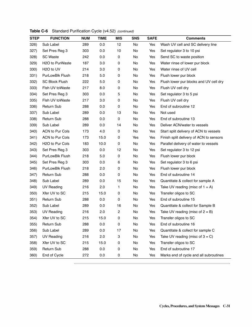
Cycles, Procedures, and System Messages C-31
326) Sub Label 289 0.0 12 No Yes Wash UV cell and SC delivery line
327) Set Pres Reg 3 303 0.0 10 No Yes Set regulator 3 to 10 psi
328) SC Waste 242 0.0 0 No Yes Send SC to waste position
329) H2O to PurWaste 187 3.0 0 No Yes Water rinse of lower pur block
330) H2O to UV 214 3.0 0 No Yes Water rinse of UV cell
331) PurLowBlk Flush 218 5.0 0 No Yes Flush lower pur block
332) SC Block Flush 222 5.0 0 No Yes Flush lower pur blocks and UV cell dry
333) Flsh UV toWaste 217 8.0 0 No Yes Flush UV cell dry
334) Set Pres Reg 3 303 0.0 5 No Yes Set regulator 3 to 5 psi
335) Flsh UV toWaste 217 3.0 0 No Yes Flush UV cell dry
336) Return Sub 288 0.0 0 No Yes End of subroutine 12
337) Sub Label 289 0.0 13 No Yes Not used
338) Return Sub 288 0.0 0 No Yes End of subroutine 13
339) Sub Label 289 0.0 14 No Yes Deliver ACN/water to vessels
340) ACN to Pur Cols 173 4.0 0 No Yes Start split delivery of ACN to vessels
341) ACN to Pur Cols 173 15.0 0 Yes Yes Finish split delivery of ACN to sensors
342) H2O to Pur Cols 183 10.0 0 No Yes Parallel delivery of water to vessels
343) Set Pres Reg 3 303 0.0 12 No Yes Set regulator 3 to 12 psi
344) PurLowBlk Flush 218 5.0 0 No Yes Flush lower pur block
345) Set Pres Reg 3 303 0.0 6 No Yes Set regulator 3 to 6 psi
346) PurLowBlk Flush 218 2.0 0 No Yes Flush lower pur block
347) Return Sub 288 0.0 0 No Yes End of subroutine 14
348) Sub Label 289 0.0 15 No Yes Quantitate & collect for sample A
349) UV Reading 216 2.0 1 No Yes Take UV reading (misc of 1 = A)
350) Xfer UV to SC 215 15.0 0 No Yes Transfer oligos to SC
351) Return Sub 288 0.0 0 No Yes End of subroutine 15
352) Sub Label 289 0.0 16 No Yes Quantitate & collect for Sample B
353) UV Reading 216 2.0 2 No Yes Take UV reading (misc of 2 = B)
354) Xfer UV to SC 215 15.0 0 No Yes Transfer oligos to SC
355) Return Sub 288 0.0 0 No Yes End of subroutine 16
356) Sub Label 289 0.0 17 No Yes Quantitate & collect for sample C
357) UV Reading 216 2.0 3 No Yes Take UV reading (misc of 3 = C)
358) Xfer UV to SC 215 15.0 0 No Yes Transfer oligos to SC
359) Return Sub 288 0.0 0 No Yes End of subroutine 17
360) End of Cycle 272 0.0 0 No Yes Marks end of cycle and all subroutines
Table C-6 Standard Purification Cycle (v4.52) (continued)
STEP FUNCTION NUM TIME MIS SNS SAFE Comments

C-32 Cycles, Procedures, and System Messages
Procedures
General Procedures are similar to cycles in that they consist of a set of functions that perform an operation. Procedures, if performed during a run, are typically performed once, while cycles are repeatedly performed during a run.
Edit BeginProcedure View
The ABI 3948 System is provided with one Begin procedure. The Start Up procedure primes all reagent delivery lines, from the reservoir to the reagent valve block, with fresh reagent.
IMPORTANT Always use this procedure prior to beginning a synthesis. Failure to perform the Begin procedure can cause a synthesis failure.
The Start Up Procedure
An example of this procedure is listed in Table C-7. To modify the procedure, copy it into a blank Begin procedure in the Edit Begin Procedure view (see “Edit Begin Procedure View” on page 6-20).
Table C-7 The Start Up Procedure (v1.35 shown)
STEP FUNCTION NUM TIME MISC SNS SAFE
1) Begin of Cycle 271 0.0 0 No Yes
2) Send Message 269 0.0 5 No Yes
3) DB 4.20H, 2.20H 110 0.0 0 No Yes
4) Clv Owns Depro 286 0.0 0 No Yes
2) Send Message 269 0.0 5 No Yes
3) DB 4.20H, 2.20H 110 0.0 0 No Yes
4) Clv Owns Depro 286 0.0 0 No Yes
5) Check Snsr Cal 320 0.0 0 No Yes
6) Heater Off 258 0.0 0 No Yes
7) Pres Reg AllOff 315 0.0 0 No Yes
8) Pres Reg AllOn 314 0.0 0 No Yes
9) Set Pres Reg 1 301 0.0 12 No Yes
10) Set Pres Reg 2 302 0.0 8 No Yes
11) Set Pres Reg 3 303 0.0 12 No Yes
12) Set Pres Reg 4 304 0.0 7 No Yes
13) Set Pres Reg 5 305 0.0 8 No Yes
14) Set Pres Reg 6 306 0.0 6 No Yes
15) Set Pres Reg 7 307 0.0 12 No Yes
16) Set Pres Reg 8 308 0.0 9 No Yes
17) Set Pres Reg 9 309 0.0 6 No Yes
18) Set Pres Reg 10 310 0.0 12 No Yes
19) Pres Reg AllOn 314 0.0 0 No Yes
20) Wait 259 15.0 0 No Yes
21) SynLowBlk Flush 65 5.0 0 No Yes
22) Go Sub 287 0.0 1 No Yes
23) IODINE to Waste 37 2.0 0 No Yes

Cycles, Procedures, and System Messages C-33
24) Go Sub 287 0.0 1 No Yes
25) TCA to Trityl 42 4.0 0 No Yes
26) ACN to Trityl 108 2.0 0 No Yes
27) LowTrityl Flush 106 5.0 0 No Yes
28) AC2O to Waste 31 2.0 0 No Yes
29) Go Sub 287 0.0 1 No Yes
30) NMI to Waste 32 2.0 0 No Yes
31) Go Sub 287 0.0 1 No Yes
32) T AMIDITE Waste 77 3.0 0 No Yes
33) C AMIDITE Waste 76 3.0 0 No Yes
34) G AMIDITE Waste 75 3.0 0 No Yes
35) A AMIDITE Waste 74 3.0 0 No Yes
36) 8 AMIDITE Waste 81 3.0 0 No Yes
37) 7 AMIDITE Waste 80 3.0 0 No Yes
38) 6 AMIDITE Waste 79 3.0 0 No Yes
39) 5 AMIDITE Waste 78 3.0 0 No Yes
40) Go Sub 287 0.0 1 No Yes
41) TET to Waste 52 2.0 0 No Yes
42) Go Sub 287 0.0 1 No Yes
43) Clv Blk Flush 144 10.0 0 No Yes
44) H2O to ClvWaste 130 5.0 0 No Yes
45) Clv Blk Flush 144 10.0 0 No Yes
46) Ammonia toWaste 115 3.0 0 No Yes
47) Dep Xfer Rinse 151 3.0 0 No Yes
48) Clv Blk Flush 144 10.0 0 No Yes
49) ACN to ClvWaste 120 2.0 0 No Yes
50) DepLowBlk Flush 153 5.0 0 No Yes
51) Gas to Coil A 156 15.0 0 No Yes
52) Gas to Coil B 157 15.0 0 No Yes
53) Gas to Coil C 158 15.0 0 No Yes
54) Pur Xfer Rinse 171 3.0 0 No Yes
55) Pur Xfer Flush 172 10.0 0 No Yes
56) Go Sub 287 0.0 2 No Yes
57) 20%ACN to Waste 197 2.0 0 No Yes
58) Go Sub 287 0.0 2 No Yes
59) H2O to PurWaste 187 2.0 0 No Yes
60) Go Sub 287 0.0 2 No Yes
61) AcAcid to Waste 202 3.0 0 No Yes
62) Go Sub 287 0.0 2 No Yes
63) TFA to Waste 192 2.0 0 No Yes
64) Tggle Vlves On 262 0.0 70 No Yes
Table C-7 The Start Up Procedure (v1.35 shown) (continued)
STEP FUNCTION NUM TIME MISC SNS SAFE

C-34 Cycles, Procedures, and System Messages
Edit End ProcedureView
Use the End procedure to flush instrument reagent lines and valve blocks at the end of each synthesis run. An example of the standard end procedure provided with the instrument is listed in Table C-8. To modify this procedure, copy it into a blank End procedure (see “Edit End Procedure View” on page 6-21).
65) PurLowBlk Flush 218 2.0 0 No Yes
66) ACN to PurWaste 177 2.0 0 No Yes
67) PurLowBlk Flush 218 5.0 0 No Yes
68) Tggle Vlves Off 263 0.0 70 No Yes
69) TEAA to Waste 182 5.0 0 No Yes
70) PurLowBlk Flush 218 5.0 0 No Yes
71) ACN to PurWaste 177 5.0 0 No Yes
72) PurLowBlk Flush 218 5.0 0 No Yes
73) Go Sub 287 0.0 2 No Yes
74) SC Waste 242 0.0 0 No Yes
75) H2O to UV 214 10.0 0 No Yes
76) Flsh UV toWaste 217 10.0 0 No Yes
77) Xfer UV to SC 215 5.0 0 No Yes
78) SC Home 243 0.0 0 No Yes
79) SC Open 245 0.0 0 No Yes
80) Goto End 290 0.0 0 No Yes
81) Sub Label 289 0.0 1 No Yes
82) ACN to SynWaste 47 3.0 0 No Yes
83) SynLowBlk Flush 65 6.0 0 No Yes
84) Return Sub 288 0.0 0 No Yes
85) Sub Label 289 0.0 2 No Yes
86) ACN to PurWaste 177 3.0 0 No Yes
87) PurLowBlk Flush 218 5.0 0 No Yes
88) Return Sub 288 0.0 0 No Yes
89) End of Cycle 272 0.0 0 No Yes
Table C-7 The Start Up Procedure (v1.35 shown) (continued)
STEP FUNCTION NUM TIME MISC SNS SAFE
Table C-8 End Procedure (v1.11 shown)
STEP FUNCTION NUM TIME MISC SNS SAFE
1 Begin of Cycle 271 0.0 0 No Yes
2 Heater Off 258 0.0 0 No Yes
3 Set Pres Reg 1 301 0.0 12 No Yes
4 Set Pres Reg 3 303 0.0 12 No Yes
5 PurUprBlk Flush 219 20.0 0 No Yes
6 PurLowBlk Flush 218 20.0 0 No Yes
7 Tggle Vlves On 262 0.0 70 No Yes
8 PurLowBlk Flush 218 20.0 0 No Yes
9 Tggle Vlves Off 263 0.0 70 No Yes

Cycles, Procedures, and System Messages C-35
10 DepUprBlk Flush 221 20.0 0 No Yes
11 Set Pres Reg 10 310 0.0 12 No Yes
12 DepLowBlk Flush 153 20.0 0 No Yes
13 Clv Blk Flush 144 20.0 0 No Yes
14 Set Pres Reg 7 307 0.0 12 No Yes
15 Set Pres Reg 9 309 0.0 0 No Yes
16 AMIDITE Vent 101 10.0 0 No Yes
17 ACN to SynWaste 47 10.0 0 No Yes
18 SynLowBlk Flush 65 20.0 0 No Yes
19 LowTrityl Flush 106 20.0 0 No Yes
20 Mix AMIDITE T 93 3.0 0 No Yes
21 Mix AMIDITE C 92 3.0 0 No Yes
22 Mix AMIDITE G 91 3.0 0 No Yes
23 Mix AMIDITE A 90 3.0 0 No Yes
24 Mix AMIDITE 8 97 3.0 0 No Yes
25 Mix AMIDITE 7 96 3.0 0 No Yes
26 Mix AMIDITE 6 95 3.0 0 No Yes
27 Mix AMIDITE 5 94 3.0 0 No Yes
28 Set Pres Reg 9 309 0.0 6 No Yes
29 SynUprBlk Flush 105 20.0 0 No Yes
30 Set Pres Reg 7 307 0.0 6 No Yes
31 Set Pres Reg 10 310 0.0 12 No Yes
32 Set Pres Reg 1 301 0.0 12 No Yes
33 Dep Xfer Flush 152 5.0 0 No Yes
34 Dep Xfer Rinse 151 3.0 0 No Yes
35 Dep Xfer Flush 152 5.0 0 No Yes
36 Gas to Coil A 156 15.0 0 No Yes
37 Gas to Coil B 157 15.0 0 No Yes
38 Gas to Coil C 158 15.0 0 No Yes
39 H20 to Coil A 163 8.0 0 No Yes
40 H20 to Coil B 164 8.0 0 No Yes
41 H20 to Coil C 165 8.0 0 No Yes
42 Gas to Coil A 156 15.0 0 No Yes
43 Gas to Coil B 157 15.0 0 No Yes
44 Gas to Coil C 158 15.0 0 No Yes
45 Pur Xfer Flush 172 10.0 0 No Yes
46 Pur Xfer Rinse 171 5.0 0 No Yes
47 Pur Xfer Flush 172 10.0 0 No Yes
48 Open All Jaws 237 0.0 0 No Yes
49 Send Message 269 0.0 5 No Yes
50 End of Cycle 272 0.0 0 No Yes
Table C-8 End Procedure (v1.11 shown) (continued)
STEP FUNCTION NUM TIME MISC SNS SAFE

C-36 Cycles, Procedures, and System Messages
Edit BottleProcedures View
Two types of procedures are located on the Edit Bottle Procedures view: Autodilute and Change procedures.
Phosphoramidite Autodilution
Use one of the Autodilute procedures to automatically dilute powdered β-cyanoethyl phosphoramidites in 2.0 gram bottles. The table below lists the Autodilute procedures available and the purpose of each.
IMPORTANT During this procedure, back-flushed phosphoramidite and excess acetonitrile contaminate the bottle contents. If you want to remove and save the phosphoramidites for later use, do not initiate this procedure.
Bottle Change Procedures (Manual Dilution)
Change Base (Chg base) Procedures for Positions A through G and Positions 5 through 8 on the instrument are intended for phosphoramidites manually diluted by the user. After you have manually diluted a bottle of phosphoramidite, use the change procedure for the phosphoramidite position on which you want to install the new bottle.
The change procedure provided in Table C-10 is representative of the Chg procedures provided. Besides change procedures for the four phosphoramidite positions, procedures are provided for changing tetrazole and ammonia.
Table C-9 List of Phosphoramidite Autodilution Procedures
Name Purpose
Autodil AGCT x.xx Simultaneously autodilutes phosphoramidites at Positions A, G, C, and T.
Autodilute-A x.xx Autodilutes phosphoramidite at Position A.
Autodilute-G x.xx Autodilutes phosphoramidite at Position G.
Autodilute-C x.xx Autodilutes phosphoramidite at Position C.
Autodilute-T x.xx Autodilutes phosphoramidite at Position T.
Table C-10 Bottle Change Procedure
Step Function Name Number Time Misc SNS Safe
1 Begin of Cycle 271 0.0 0 No Yes
2 Set Press Reg 9 309 0.0 0 No Yes
3 AMIDITE Vent 101 30.0 0 No Yes
4 ACN AMIDITE 5 86 4.0 0 No Yes
5 Mix ACN AMIDITE 5 94 5.0 0 No Yes
6 Send Message 292 0.0 10 No Yes
7 Send Message 292 0.0 1 No Yes
8 Pause Chemistry 291 0.0 0 No Yes
9 Set Press Reg 9 309 0.0 6 No Yes
10 ACN to SynWaste 47 3.0 0 No Yes
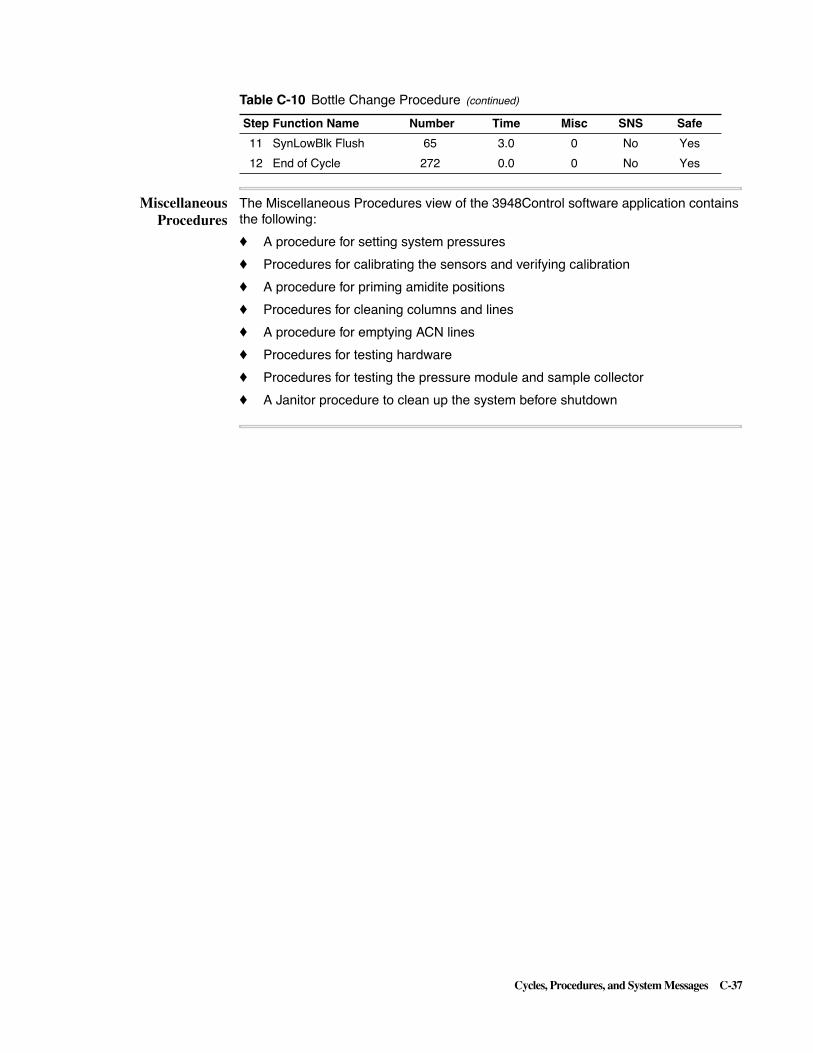
Cycles, Procedures, and System Messages C-37
MiscellaneousProcedures
The Miscellaneous Procedures view of the 3948Control software application contains the following:
� A procedure for setting system pressures
� Procedures for calibrating the sensors and verifying calibration
� A procedure for priming amidite positions
� Procedures for cleaning columns and lines
� A procedure for emptying ACN lines
� Procedures for testing hardware
� Procedures for testing the pressure module and sample collector
� A Janitor procedure to clean up the system before shutdown
11 SynLowBlk Flush 65 3.0 0 No Yes
12 End of Cycle 272 0.0 0 No Yes
Table C-10 Bottle Change Procedure (continued)
Step Function Name Number Time Misc SNS Safe
C-38 Cycles, Procedures, and System Messages
System Messages
Instrument Statusand Message
Indicators
Instrument Status Messages
The following instrument status messages appear in the upper right corner of all Synthesizer Window views to indicate the current instrument condition:
� Ready - the instrument is idle and ready for a run to be initiated
� Running - the instrument is currently running chemistry
� Interrupted - a run in progress has been interrupted
� Manual Control - a manual control action is in progress
Note It is important to be aware of what state the instrument is in at the time of a system message.
Message Waiting/Critical Message Waiting
These messages are presented in the upper left corner of all Synthesizer Window views except the Monitor Chemistry View, to indicate that an important message is currently presented in the log on the bottom of the Monitor Chemistry View.
Types of Messages There are three types of messages generated for the 3948 instrument and flagged by message indicators:
� Regular Reports to the Monitor Chemistry view
� Critical messages presented in the Monitor Chemistry window
� Microphone Only messages or messages stored in a Microphone file (not shown in Monitor Chemistry).
These message types are flagged as follows:
� Regular Reports messages are flagged on any ABI 3948 System Control view by “Message Waiting”.
� Critical messages are flagged on any ABI 3948 System Control view by “Critical Message Waiting.”
� Microphone Only messages are not available during a run but can be examined at the conclusion of the run.
Proceed to the log on the bottom of the Monitor Chemistry view to see the particular message indicated by a message indicator.

Cycles, Procedures, and System Messages C-39
Categories ofMessages
Messages presented in the Monitor Chemistry view or in a Microphone file can be further categorized as Operator, Instrument, or General Activity messages:
� Operator messages are the messages prefaced by “Error:” or “Caution:”
� Instrument messages are the messages prefaced by “Attention:” or “Note”.
� General Activity messages are the messages without the “Error”, “Caution”, “Attention”, or “Note” prefaces.
Some examples of conditions which may generate these three categories of messages are listed under the discussions for the message types below. For a listing of the relative severity of Operator and Instrument message, see “Hierarchical Messages” on page C-43.
MessageConventions
The type of activities which may be flagged by the three categories of message are listed below:
Operator Messages
Operator messages, those messages prefaced by “Error” or “Caution,” are generated by the types of activities outlined below.
Note A hierarchy of Operator messages is presented under “Hierarchical Messages” on page C-43.
Message Preface Type of Activity
Error Characterized by Cycle programming or Manual Control parameter errors:
– Using functions from the wrong chemistry module controller
– Ramping function parameter(s) not set or out of range
– Other out-of-range values (illegal pressure or regulator number)
Note Messages report values substituted at range limits.
Caution Characterized by Discretionary bending of optimal operational rules:
– Allowing deliveries to open jaws
– Setting temperature wait time too short to reach setpoint

C-40 Cycles, Procedures, and System Messages
Instrument Messages
Instrument messages, those messages prefaced by “Attention” or “Note,” are generated by the types of activities outlined below.
General Activity Messages
General Activity messages, messages with no preface, are generated by the types of activities outlined below.
The three types of messages are listed in separate subsections below with the information needed to interpret them.
Note The examples provided in the three listings are representative of those you might see in the Monitor Chemistry view window or in the Microphone file for a run and are generally self explanatory.
Regular ReportsMessages
This type of message contains all three categories of messages: Operator, Instrument, and General Activity.
Messages from these functions: Send Message (269) and Comment (270)
Note The Send Message command is used in bottle change procedures to instruct the operator to take some action.
Resetting the Database.Pausing system. Resuming System. Pausing system: will auto-resume in 15 minutes.Data Base has been reset.
Message Preface Type of Activity
Attention Reports events likely to impact instrument performance
– - Transfers missed
– - Sensor never triggered
– - Jaw leak test failures and subsequent oligo drop outs
Note Indicates minor and/or infrequent operational events:
– Retries
– Recoveries
– Sensor did not verify
– Other miscellaneous events
Message Preface Type of Activity
No leader or message preface
Reports instrument actions and hardware status, mostly to Microphone:
– Run and Manual Control start/end/abort/pause/resume
– Turntable moves
– Jaw activity: open/close/leak test results
– Regulator setpoint changes
– Other: low pressure, a/d reference voltage, s/c motor problems
– Etc.

Cycles, Procedures, and System Messages C-41
Changed Instrument Name. Pause Switch Pushed.Resume with columns 4-6 in the load position.Starting Chemistry Run: [Image version], [Database version].Aborting Chemistry: [Image version], [Database version].Chemistry Done: [Image version], [Database version].Stopping Manual Control Action. Aborting Manual Control. Turntable move 10 completed.Pausing System at turntable position 12.Jaw pressure check retry failed during synthesis.Initial synthesis pressure check failed: now retrying.Regulator '23' does not exist.Power Fail at 10/27/97 09:23:36.A to D reference voltage 3.5 out of range.Rack selection changed.Note: turntable move retried.Note: low input pressure detected.Note: used Xfer Clv Col A recovery.Note: function BackFlsh Purs retried 4 times.(to µphone only if <4)Note: function TCA to Syn Cols retried A column 4 times.Note: heater was turned off after 180 minutes.Attention: Xfer Clv Col C transfer missed.Attention: C+TET to column B sensor never triggered.Attention: sensor never triggered at pur step 188.Attention: leak detected in synthesis jaw/blocks.Attention: oligos 10-12 discontinued during synthesis.Caution: temp set to 35°, reached 36° in 300 seconds.Error: cannot set regulator 10 to 15 psi, 12 psi limit used.Error: used minimum heater setpoint of 15 instead of 10.Error: used maximum heater setpoint of 70 instead of 85.Error 0 readings requested: minimum valule of 1 used.Error: 10 trip readings requested, used current max. 7.Error: 10 check readings requested, used current max. 5.Error: 20 readings requested: maximum value of 10 used.Error: 10 trip readings reduced to new maximum of 7.sError: 10 check readings reduced to new maximum of 7.Error: 20000ms sensor delay requested: maximum 2280.Error: misc parameter must be: 1 = syn, 2 = clv, or 3 = pur.Error: If First Cycle only works in synthesis cycles.Error: End Row SCP/123 only works in Manual Control.Error: no active oligos in cleavage to be discontinued.Error: cannot end row because purification is inactive.Error: oligos 7-9 now in cleavage are already discontinued.Error: 999 heater time requested, used maximum 480.

C-42 Cycles, Procedures, and System Messages
Critical Messages This type of message contains only the General Activity category of message.
Note Send Message function messages maybe be made 'critical' by selecting liquid sensor use.
Manual Control Paused: Resume instead of Running. Sample Collector door open. Pausing System. Jaw move failure. Pausing System. Jaws open? Check jaws and Instrument Monitor Window.Invalid RunS file: no cycles selected to run.Invalid SeqL file: maximum sequence length exceeded. Turntable May Be Out Of Position.Regulators shut down due to low input pressure. Synthesis jaw did not open. Cleavage jaw did not close. Sensor Calibration Problem. Pausing System. Illegal valve set! Valves left off. Pausing System.TTextFile::WriteData index = 501, max = 500TTextFile::ReadData index = 501, max = 500TStructFile::WriteData index = 501, max = 500TStructFile::ReadData index = 501, max = 500Jaws open: clv & pur! Valves left off. Pausing System.Powerfail interrupted jaw open. Pausing System.Powerfail interrupted jaw close. Pausing System.Powerfail interrupted needle up move Pausing System.Powerfail interrupted needle down move Pausing System.Powerfail interrupted turntable move Pausing System.Coil temperature 100°C is out of range. Pausing System.Sample Collector Z Motor Timed Out. Pausing System.Instrument in use: rack selection not changed.Row ended: advance collector into position for next row.Caution: reagent deliveries to open jaws enabled. Error: Amidite bottle 'A' appears to be empty.
Microphone-onlymessages
This type of message contains only the General Activity category of message.
Starting Manual Control Action. Pausing Manual Control. Resuming Manual Control. Manual Control Action Complete. Coil temperature has been set to 35°C.Coil temperature has been set to 65°C for deprotection.Temp set to 38°, reached 38° in 281 seconds.Name or Msg;Snsr; msecs; °C;Step; Ttbl(Microphone log column headings)Synthesis A cycle ended.Cleavage cycle ended.Purification cycle ended.Changing regulator 10 from 6 psi to 12 psi.LogSensor Output (the standard sensor function report line)Wet(11B) ≥ 9/10 Hg: 2232 1 1 1 1 1 1 1 1 1 5 14|14 (histogram)Voltage[A]: -2.13Results[A]: 3.2 odu 18.3 pmole

Cycles, Procedures, and System Messages C-43
Syn P 0.01 N -.-- Clv P 0.02 N-.-- Pur F 0.54 P 0.49 (1st line of 2)Tested at 12 psi, 2.00 passes (2nd line of 2)Ramping function parameter not set. Pausing System.PSIs: 10.200 6.532 10.200 6.532 10.200 6.532 10.200 6.532 10.200 6.532 Leak Test: 10.02 9.98 0.04 PWait On Pur Flg; 00:12:21Depro Heater/Fan Test STARTINGDepro Heater Test RUNNING Temp= 27, HtrCur=1200Depro Fan Test RUNNING Temp=35, FanCur= 60Depro Heater/Fan Test COMPLETEDepro Htr Wait ensuring 60 minute deprotection; 00:12:21Time Stamp; 00:12:21; 33Coils have been hot for 63 minutes.Synthesis jaw open elapsed time = 1567 ms.Cleavage jaw close elapsed time = 1786 ms.Sample Collector Z Motor Home Flag Error.Note: function BackFlsh Purs retried 1 times.Note: sensor 23B did not verify.Note: function TCA to Syn Cols retried A column 3 times.
HierarchicalMessages
The list below presents a hierarchical list of Operator and Instrument category messages, ranging from conditions most likely to negatively affect a run at the top to those least likely at the bottom. This hierarchy applies both to the individual messages within each type (Error, Caution, Attention, Note) and to the relative severity of each of these types of message.
Error: Amidite bottle 'G' appears to be empty.B+TETError: 0 readings requested, used minimum value 1.RampingError: 20 readings requested, used maximum value 10.Error: 10 trip readings reduced to new maximum of 7.Error: 9 check readings reduced to new maximum of 7.Error: 0 trip readings requested, used minimum value 1. Error: 10 trip readings requested, used current max. 7. Error: 9 check readings requested, used current max. 7. Error: 20000ms sensor delay requested, used maximum 2280.Error: used minimum heater setpoint of 15 instead of 10.HeaterError: used maximum heater setpoint of 70 instead of 85.Error: cannot set regulator 10 to 15 psi, 12 psi limit used.OtherError: misc parameter must be: 1 = syn, 2 = clv, or 3 = pur.Error: If First Cycle only works in synthesis cycles.Error: End Row SCP/123 only works in Manual Control.Error: no active oligos in cleavage to be discontinued.Error: oligos 7-9 now in cleavage are already discontinued.Error: 999 heater time requested, used maximum 480.
Caution: reagent deliveries to open jaws enabled.Caution: temp set to 35°, reached 36° in 300 secs.
Attention: 'G'+TET to column B sensor never triggered. Attention: sensor never triggered at pur step 10. Attention: Xfer Clv Col C transfer missed.Attention: Leak detected during in synthesis jaw/blocks.Attention: Oligos 10-12 discontinued during synthesis.

C-44 Cycles, Procedures, and System Messages
Note: function BackFlsh Purs retried 1 times.Note: function TCA to Syn Cols retried A column 3 times.Note: sensor 23B did not verify.Note: used Xfer Clv Col A recovery.Note: turntable move retried. Note: low input pressure detected.Note: heater was turned off after 180 minutes.

ABI 3948 System Function List and Other Cycles D-1
3948 System Function List and Other Cycles D
In This Appendix
Topics Covered This appendix contains a detailed ABI 3948 System function list as well as the additional purification cycles listed below:
Topic See page
ABI 3848 System Function List D-2
The Purification Dye Cycle D-33
The Purification Biotin Cycle D-42
D

D-2 ABI 3948 System Function List and Other Cycles
ABI 3948 System Function List
List of FunctionsTable D-1 lists the functions available for the ABI 3948 System.
Table D-1 ABI 3948 System Function List (v4.20, 2.20)
Numb Name Valve List Valve Description
1 B+ TET to Syns 4 Tetrazole
22 SynUpr to Waste
Note Function 1 is a “macro” function. This means that the particular valves used vary depending upon the sequence composition and the column to which delivery is made. This function makes three separate serial amidite deliveries to one column rather than a single simultaneous (parallel) delivery to all three columns
2 A + TET to Syn A 4 Tetrazole
9 "A" Amidite
15 Syn Col A Lower
22 SynUpr to Waste
26 Syn Col A Upper
3 G+ TET to Syn A 4 Tetrazole
10 "G" Amidite
15 Syn Col A Lower
22 SynUpr to Waste
26 Syn Col A Upper
4 C+ TET to Syn A 4 Tetrazole
11 "C" Amidite
15 Syn Col A Lower
22 SynUpr to Waste
26 Syn Col A Upper
5 T+ TET to Syn A 4 Tetrazole
12 "T" Amidite
15 Syn Col A Lower
22 SynUpr to Waste
26 Syn Col A Upper
6 5+ TET to Syn A 4 Tetrazole
5 "5" Amidite
15 Syn Col A Lower
22 SynUpr to Waste
26 Syn Col A Upper
7 6+ TET to Syn A 4 Tetrazole
6 "6" Amidite
15 Syn Col A Lower
22 SynUpr to Waste
26 Syn Col A Upper

ABI 3948 System Function List and Other Cycles D-3
8 7+ TET to Syn A 4 Tetrazole
7 "7" Amidite
15 Syn Col A Lower
22 SynUpr to Waste
26 Syn Col A Upper
9 8+ TET to Syn A 4 Tetrazole
8 "8" Amidit
15 Syn Col A Lower
22 SynUpr to Waste
26 Syn Col A Upper
10 A+ TET to Syn B 4 Tetrazole
9 "A" Amidite
14 Syn Col B Lower
22 SynUpr to Waste
25 Syn Col B Upper
11 G+ TET to Syn B 4 Tetrazole
10 "G" Amidite
14 Syn Col B Lower
22 SynUpr to Waste
25 Syn Col B Upper
12 C+ TET to Syn B 4 Tetrazole
11 "C" Amidite
14 Syn Col B Lower
22 SynUpr to Waste
25 Syn Col B Upper
13 T+ TET to Syn B 4 Tetrazole
12 "T" Amidite
14 Syn Col B Lower
22 SynUpr to Waste
25 Syn Col B Upper
14 5+ TET to Syn B 4 Tetrazole
5 "5" Amidite
14 Syn Col B Lower
22 SynUpr to Waste
25 Syn Col B Upper
15 6+ TET to Syn B 4 Tetrazole
6 "6" Amidite
14 Syn Col B Lower
22 SynUpr to Waste
25 Syn Col B Upper
16 7+ TET to Syn B 4 Tetrazole
Table D-1 ABI 3948 System Function List (v4.20, 2.20)
Numb Name Valve List Valve Description

D-4 ABI 3948 System Function List and Other Cycles
7 "7" Amidite
14 Syn Col B Lower
22 SynUpr to Waste
25 Syn Col B Upper
17 8+ TET to Syn B 4 Tetrazole
8 "8" Amidite
14 Syn Col B Lower
22 SynUpr to Waste
25 Syn Col B Upper
18 A+ TET to Syn C 4 Tetrazole
9 "A" Amidite
13 Syn Col C Lower
22 SynUpr to Waste
24 Syn Col C Upper
19 G+ TET to SynC 4 Tetrazole
10 "G" Amidite
13 Syn Col C Lower
22 SynUpr to Waste
24 Syn Col C Upper
20 C+ TET to Syn C 4 Tetrazole
11 "C" Amidite
13 Syn Col C Lower
22 SynUpr to Waste
24 Syn Col C Upper
21 T+ TET to Syn C 4 Tetrazole
12 "T" Amidite
13 Syn Col C Lower
22 SynUpr to Waste
24 Syn Col C Upper
22 5+ TET to Syn C 4 Tetrazole
5 "5" Amidite
13 Syn Col C Lower
22 SynUpr to Waste
24 Syn Col C Upper
23 6+ TET to Syn C 4 Tetrazole
6 "6" Amidite
13 Syn Col C Lower
22 SynUpr to Waste
24 Syn Col C Upper
24 7+ TET to Syn C 4 Tetrazole
7 "7" Amidite
Table D-1 ABI 3948 System Function List (v4.20, 2.20)
Numb Name Valve List Valve Description

ABI 3948 System Function List and Other Cycles D-5
13 Syn Col C Lower
22 SynUpr to Waste
24 Syn Col C Upper
25 8+ TET to Syn C 4 Tetrazole
8 "8" Amidite
13 Syn Col C Lower
22 SynUpr to Waste
24 Syn Col C Upper
26 Coupling Wait Waits according to the time in the B+TET Calibration table.
27 CAP to Syn Cols 13 Syn Col C Lower
14 Syn Col B Lower
15 Syn Col A Lower
16 Xfr to SynLow
17 NMI
18 Ac20
22 SynUpr to Waste
24 Syn Col C Upper
25 Syn Col B Upper
26 Syn Col A Upper
28 CAP to SynCol A 15 Syn Col A Lower
16 Xfr to SynLow
17 NMI
18 Ac20
22 SynUpr to Waste
26 Syn Col A Upper
29 CAP to SynCol B 14 Syn Col B Lower
16 Xfr to SynLow
17 NMI
18 Ac20
22 SynUpr to Waste
25 Syn Col B Upper
30 CAP to SynCol C 13 Syn Col C Lower
16 Xfr to SynLow
17 NMI
18 Ac20
22 SynUpr to Waste
24 Syn Col C Upper
31 AC20 to Waste 18 Ac20
21 SynLow to Waste
32 NMI to Waste 17 NMI
Table D-1 ABI 3948 System Function List (v4.20, 2.20)
Numb Name Valve List Valve Description

D-6 ABI 3948 System Function List and Other Cycles
21 SynLow to Waste
33 IODINE to Syns 13 Syn Col C Lower
14 Syn Col B Lower
15 Syn Col A Lower
16 Xfr to SynLow
20 Iodine
22 SynUpr to Waste
24 Syn Col C Upper
25 Syn Col B Upper
26 Syn Col A Upper
34 IODINE to Syn A 15 Syn Col A Lower
16 Xfr to SynLow
20 Iodine
22 SynUpr to Waste
26 Syn Col A Upper
35 IODINE to Syn B 14 Syn Col B Lower
16 Xfr to SynLow
20 Iodine
22 SynUpr to Waste
25 Syn Col B Upper
36 IODINE to Syn C 13 Syn Col C Lower
16 Xfr to SynLow
20 Iodine
22 SynUpr to Waste
24 Syn Col C Upper
37 IODINE to Waste 20 Iodine
21 SynLow to Waste
38 TCA to Syn Cols 13 Syn Col C Lower
14 Syn Col B Lower
15 Syn Col A Lower
16 Xfr to SynLow
19 TCA
23 SynUpr to Trityl
24 Syn Col C Upper
25 Syn Col B Upper
26 Syn Col A Upper
39 TCA to SynCol A 15 Syn Col A Lower
16 Xfr to SynLow
19 TCA
23 SynUpr to Trityl
26 Syn Col A Upper
Table D-1 ABI 3948 System Function List (v4.20, 2.20)
Numb Name Valve List Valve Description

ABI 3948 System Function List and Other Cycles D-7
40 TCA to SynCol B 14 Syn Col B Lower
16 Xfr to SynLow
19 TCA
23 SynUpr to Trityl
25 Syn Col B Upper
41 TCA to SynCol C 13 Syn Col C Lower
16 Xfr to SynLow
19 TCA
23 SynUpr to Trityl
24 Syn Col C Upper
42 TCA to Trityl 19 TCA
21 SynLow to Waste
72 SynLow to Trityl
43 ACN to Syn Cols 1 ACN to Syn
13 Syn Col C Lower
14 Syn Col B Lower
15 Syn Col A Lower
22 SynUpr to Waste
24 Syn Col C Upper
25 Syn Col B Upper
26 Syn Col A Upper
44 ACN to SynCol A 1 ACN to Syn
15 Syn Col A Lower
22 SynUpr to Waste
26 Syn Col A Upper
45 ACN to SynCol B 1 ACN to Syn
14 Syn Col B Lower
22 SynUpr to Waste
25 Syn Col B Upper
46 ACN to SynCol C 1
13 Syn Col C Lower
22 SynUpr to Waste
24 Syn Col C Upper
47 CN to SynWaste 1 ACN to Syn
16 Xfr to SynLow
21 SynLow to Waste
48 TET to Syn Cols 4 Tetrazole
13 Syn Col C Lower
14 Syn Col B Lower
15 Syn Col A Lower
22 SynUpr to Waste
Table D-1 ABI 3948 System Function List (v4.20, 2.20)
Numb Name Valve List Valve Description

D-8 ABI 3948 System Function List and Other Cycles
24 Syn Col C Upper
25 Syn Col B Upper
26 Syn Col A Upper
49 TET to SynCol A 4 Tetrazole
15 Syn Col A Lower
22 SynUpr to Waste
26 Syn Col A Upper
50 TET to SynCol B 4 Tetrazole
14 Syn Col B Lower
22 SynUpr to Waste
25 Syn Col B Upper
51 TET to Syn Col C 4 Tetrazole
13 Syn Col C Lower
22 SynUpr to Waste
24 Syn Col C Upper
52 TET to Waste 4 Tetrazole
16 Xfr to SynLow
21 SynLow to Waste
53 Flush Syn Cols 2 Gas to Syn
13 Syn Col C Lower
14 Syn Col B Lower
15 Syn Col A Lower
22 SynUpr to Waste
24 Syn Col C Upper
25 Syn Col B Upper
26 Syn Col A Upper
54 Flush Syn Col A 2 Gas to Syn
15 Syn Col A Lower
22 SynUpr to Waste
26 Syn Col A Upper
55 Flush Syn Col B 2 Gas to Syn
14 Syn Col B Lower
22 SynUpr to Waste
25 Syn Col B Upper
56 Flush Syn Col C 2 Gas to Syn
13 Syn Col C Lower
22 SynUpr to Waste
24 Syn Col C Upper
57 Back Flush Syns 13 Syn Col C Lower
14 Syn Col B Lower
15 Syn Col A Lower
Table D-1 ABI 3948 System Function List (v4.20, 2.20)
Numb Name Valve List Valve Description

ABI 3948 System Function List and Other Cycles D-9
16 Xfr to SynLow
21 SynLow to Waste
24 Syn Col C Upper
25 Syn Col B Upper
26 Syn Col A Upper
28 Gas to Syn Upper
58 Back Flush Syn A 15 Syn Col A Lower
16 Xfr to SynLow
21 SynLow to Waste
26 Syn Col A Upper
28 Gas to Syn Upper
59 Back Flush Syn B 14 Syn Col B Lower
16 Xfr to SynLow
21 SynLow to Waste
25 Syn Col B Upper
28 Gas to Syn Upper
60 Back Flush Syn C 13 Syn Col C Lower
16 Xfr to SynLow
21 SynLow to Waste
24 Syn Col C Upper
28 Gas to Syn Upper
61 TritylFlsh Syns 2 Gas to Syn
13 Syn Col C Lower
14 Syn Col B Lower
15 Syn Col A Lower
23 SynUpr to Trityl
24 Syn Col C Upper
25 Syn Col B Upper
26 Syn Col A Upper
62 TritylFlsh SynA 2 Gas to Syn
15 Syn Col A Lower
23 SynUpr to Trityl
26 Syn Col A Upper
63 TritylFlsh SynB 2 Gas to Syn
14 Syn Col B Lower
23 SynUpr to Trityl
25 Syn Col B Upper
64 TritylFlsh SynC 2 Gas to Syn
13 Syn Col C Lower
23 SynUpr to Trityl
24 Syn Col C Upper
Table D-1 ABI 3948 System Function List (v4.20, 2.20)
Numb Name Valve List Valve Description

D-10 ABI 3948 System Function List and Other Cycles
65 SynLowBlk Flush 2 Gas to Syn
16 Xfr to SynLow
21 SynLow to Waste
66 Syn Upper Vent 22 SynUpr to Waste
24 Syn Col C Upper
25 Syn Col B Upper
26 Syn Col A Upper
67 Syn Lower Vent 13 Syn Col C Lower
14 Syn Col B Lower
15 Syn Col A Lower
16 Xfr to SynLow
21 SynLow to Waste
68 ACN to AGCT 1 ACN to Syn
9 “A” Amidite
10 “G” Amidite
11 “C” Amidite
12 “T” Amidite
76 Amidite Vent
69 ACN to TET 1 ACN to Syn
4 Tetrazole
70 ACN to TCA 1 ACN to Syn
16 Xfr to SynLow
19 TCA
71 ACN to IODINE 1 ACN to Syn
16 Xfr to SynLow
20 Iodine
72 ACN to AC20 1 ACN to Syn
16 Xfr to SynLow
18 Ac20
73 ACN to NMI 1 ACN to Syn
16 Xfr to SynLow
17 NMI
74 A AMIDITE Waste 9 "A" Amidite
16 Xfr to SynLow
21 SynLow to Waste
75 G AMIDITE Waste 10 "G" Amidite
16 Xfr to SynLow
21 SynLow to Waste
Table D-1 ABI 3948 System Function List (v4.20, 2.20)
Numb Name Valve List Valve Description

ABI 3948 System Function List and Other Cycles D-11
D 3948 Function List and Other Cycles
Table D-1 ABI 3948 System Function List (v4.20, 2.20)
Numb Name Valve List Valve Description
76 C AMIDITE Waste 11 "C" Amidite
16 Xfr to SynLow
21 SynLow to Waste
77 T AMIDITE Waste 12 "T" Amidite
16 Xfr to SynLow
21 SynLow to Waste
78 5 AMIDITE Waste 5 "5" Amidite
16 Xfr to SynLow
21 SynLow to Waste
79 6 AMIDITE Waste 6 "6" Amidite
16 Xfr to SynLow
21 SynLow to Waste
80 7 AMIDITE Waste 7 "7" Amidite
16 Xfr to SynLow
21 SynLow to Waste
81 8 AMIDITE Waste 8 "8" Amidite
16 Xfr to SynLow
21 SynLow to Waste
82 ACN AMIDITE A 1 ACN to Syn
9 "A" Amidite
76 Amidite Vent
83 ACN AMIDITE G 1 ACN to Syn
10 "G" Amidite
76 Amidite Vent
84 ACN AMIDITE C 1 ACN to Syn
11 "C" Amidite
76 Amidite Vent
85 ACN AMIDITE T 1 ACN to Syn
12 "T" Amidite
76 Amidite Vent
86 ACN AMIDITE 5 1 ACN to Syn
5 "5" Amidite
76 Amidite Vent
87 ACN AMIDITE 6 1 ACN to Syn
6 "6" Amidite
76 Amidite Vent
88 ACN AMIDITE 7 1 ACN to Syn
7 "7" Amidite
76 Amidite Vent
89 ACN AMIDITE 8 1 ACN to Syn

D-12 ABI 3948 System Function List and Other Cycles
8 "8" Amidite
76 Amidite Vent
90 Mix AMIDITE A 2 Gas to Syn
9 "A" Amidite
76 Amidite Vent
91 Mix AMIDITE G 2 Gas to Syn
10 "G" Amidite
76 Amidite Vent
92 Mix AMIDITE C 2 Gas to Syn
11 "C" Amidite
76 Amidite Vent
93 Mix AMIDITE T 2 Gas to Syn
12 "T" Amidite
76 Amidite Vent
94 Mix AMIDITE 5 2 Gas to Syn
5 "5" Amidite
76 Amidite Vent
95 Mix AMIDITE 6 2 Gas to Syn
6 "6" Amidite
76 Amidite Vent
96 Mix AMIDITE 7 2 Gas to Syn
7 "7" Amidite
76 Amidite Vent
97 Mix AMIDITE 8 2 Gas to Syn
8 8" Amidite
76 Amidite Vent
98 Mix AGCT 2 Gas to Syn
9 'A" Amidite
10 "G" Amidite
11 "C" Amidite
12 "T" Amidite
76 Amidite Vent
99 MIX AG 2 Gas to Syn
9 "A" Amidite
10 "G" Amidite
76 Amidite Vent
100 MIX CT 2 Gas to Syn
11 "C" Amidite
12 "T" Amidite
76 Amidite Vent
101 AMIDITE Vent 76 Amidite Vent
Table D-1 ABI 3948 System Function List (v4.20, 2.20)
Numb Name Valve List Valve Description

ABI 3948 System Function List and Other Cycles D-13
102 Ammonia Vent 74 Ammonia Vent
103 Mix Ammonia 29 Gas to Clv Lower
32 Ammonia
74 Ammonia Vent
104 Mix Tetrazole 2 Gas to Syn
4 Tetrazole
105 SynUprBlk Flush 22 SynUpr to Waste
28 Gas to Syn Upper
106 LowTrityl Flush 2 Gas to Syn
16 Xfr to SynLow
21 SynLow to Waste
72 SynLow to Trityl
107 UprTrityl Flush 23 SynUpr to Trityl
28 Gas to Syn Upper
108 ACN to Trityl 1 ACN to Syn
16 Xfer to SynLow
21 SynLow to Waste
72 SynLow to Trityl
109 Waste to Trityl
Numb Name Purpose of Function
110 Database Version This function is used to indicate the database version.
111 Ammonia to Clvs 32 Ammonia
33 Clv Col C Lower
34 Clv Col B Lower
35 Clv Col A Lower
112 Ammonia to ClvA 32 Ammonia
35 Clv Col A Lower
113 Ammonia to ClvB 32 Ammonia
34 Clv Col B Lower
114 Ammonia to ClvC 32 Ammonia
33 Clv Col C Lower
115 Ammonia toWaste 32 Ammonia
39 Xfr Clv to Dep
43 DepLow to Waste
116 ACN to Clv Cols 33 Clv Col C Lower
34 Clv Col B Lower
35 Clv Col A Lower
38 ACN to Dep Lower
39 Xfr Clv to Dep
117 ACN to ClvCol A 35 Clv Col A Lower
Table D-1 ABI 3948 System Function List (v4.20, 2.20)
Numb Name Valve List Valve Description

D-14 ABI 3948 System Function List and Other Cycles
38 ACN to Dep Lower
39 Xfr Clv to Dep
118 ACN to ClvCol B 34 Clv Col B Lower
38 ACN to Dep Lower
39 Xfr Clv to Dep
119 ACN to ClvCol C 33 Clv Col C Lower
38 ACN to Dep Lower
39 Xfr Clv to Dep
120 ACN to ClvWaste 38 ACN to Dep Lower
43 DepLow to Waste
121 Gas to Clv Cols 29 Gas to Clv Lower
33 Clv Col C Lower
34 Clv Col B Lower
35 Clv Col A Lower
122 Gas to ClvCol A 29 Gas to Clv Lower
35 Clv Col A Lower
123 Gas to ClvCol B 29 Gas to Clv Lower
34 Clv Col B Lower
124 Gas to ClvCol C 29 Gas to Clv Lower
33 Clv Col C Lower
125 Gas to Clv II 33 Clv Col C Lower
34 Clv Col B Lower
35 Clv Col A Lower
37 Gas to Dep Lower
39 Xfr Clv to Dep
126 H2O to Clv Cols 31 H2O to Clv Lower
33 Clv Col C Lower
34 Clv Col B Lower
35 Clv Col A Lower
127 H2O to ClvCol A 31 H2O to Clv Lower
35 Clv Col A Lower
128 H2O to ClvCol B 31 H2O to Clv Lower
34 Clv Col B Lower
129 H2O to ClvCol C 31 H2O to Clv Lower
33 Clv Col C Lower
130 H2O to ClvWaste 31 H2O to Clv Lower
39 Xfr Clv to Dep
43 DepLow to Waste
131 Back Flush Clvs 33 Clv Col C Lower
34 Clv Col B Lower
Table D-1 ABI 3948 System Function List (v4.20, 2.20)
Numb Name Valve List Valve Description

ABI 3948 System Function List and Other Cycles D-15
35 Clv Col A Lower
39 Xfr Clv to Dep
43 DepLow to Waste
75 Gas to Clv Upper
132 Back flush Clv A 35 Clv Col A Lower
39 Xfr Clv to Dep
43 DepLow to Waste
75 Gas to Clv Upper
133 Back flush Clv B 34 Clv Col B Lower
39 Xfr Clv to Dep
43 DepLow to Waste
75 Gas to Clv Upper
134 Back flush Clv C 33 Clv Col C Lower
39 Xfr Clv to Dep
43 DepLow to Waste
75 Gas to Clv Upper
135 Crude A to UV 37 Gas to Dep Lower
40 Coil A Input
46 Coil A Exit
49 Xfr from Dep
58 Xfr from Dep
62 Xfr to UV
136 Crude B to UV 37 Gas to Dep Lower
41 Coil B Input
47 Coil B Exit
49 Xfr from Dep
58 Xfr from Dep
62 Xfr to UV
137 Crude C to UV 37 Gas to Dep Lower
42 Coil C Input
48 Coil C Exit
49 Xfr from Dep
58 Xfr from Dep
62 Xfr to UV
138 Press Line 29 Gas to Clv Lower
139 Compress 75 Gas to Clv Upper
140 Clv Vent 33 Clv Col C Lower
34 Clv Col B Lower
35 Clv Col A Lower
39 Xfr Clv to Dep
43 DepLow to Waste
Table D-1 ABI 3948 System Function List (v4.20, 2.20)
Numb Name Valve List Valve Description

D-16 ABI 3948 System Function List and Other Cycles
141 Xfer Clv Col A 35 Clv Col A Lower
39 Xfr Clv to Dep
40 Coil A Input
46 Coil A Exit
50 DepUpr to Waste
75 Gas to Clv Upper
Note Functions 141, 142, and 143 “ramp up” the pressure from the regulator until the sample leaves the coil during a cleavage cycle. In examining the cycle in the Edit Cleavage Cycle view, the value in the MISC field is the regulator being ramped and theTIME field is the time between ramps. These functions will ramp up to four times before quitting. Ramping only works when “Yes” is selected for the SNS field.
To observe the range of pressure over which one of these functions is ramped for a particular regulator, change to the Monitor Instrument view while the function is being executed.
The following functions are also ramping functions:
� 135–137 Crude to UV
� 162-168 Xfer Coil
� 211-213 Pur to UV
142 Xfer Clv Col B 34 Clv Col B Lower
39 Xfr Clv to Dep
41 Coil B Input
47 Coil B Exit
50 DepUpr to Waste
75 Gas to Clv Upper
143 Xfer Clv Col C 33 Clv Col C Lower
39 Xfr Clv to Dep
42 Coil C Input
48 Coil C Exit
50 DepUpr to Waste
75 Gas to Clv Upper
144 Clv Blk Flush 29 Gas to Clv Lower
39 Xfr Clv to Dep
43 DepLow to Waste
Table D-1 ABI 3948 System Function List (v4.20, 2.20)
Numb Name Valve List Valve Description

ABI 3948 System Function List and Other Cycles D-17
D 3948 Function List and Other Cycles
Table D-1 ABI 3948 System Function List (v4.20, 2.20)
Numb Name Valve List Valve Description
145 Ammonia to SynA 3 Xfer from Syn
15 Syn Col A Lower
22 SynUpr to Waste
26 Syn Col A Upper
30 Xfr to Clv Lower
32 Ammonia
146 Ammonia to SynB 3 Xfer from Syn
14 Syn Col B Lower
22 SynUpr to Waste
25 Syn Col B Upper
30 Xfr to Clv Lower
32 Ammonia
147 Ammonia to SynC 3 Xfer from Syn
13 Syn Col C Lower
22 SynUpr to Waste
24 Syn Col C Upper
30 Xfr to Clv Lower
32 Ammonia
148 Syn ACN to Clv 1 ACN to Syn
3 Xfer from Syn
30 Xfr to Clv Lower
39 Xfer Clv to Dep
43 DepLow to Waste
149 Flsh Syn to Clv 2 Gas to Syn
3 Xfer from Syn
30 Xfr to Clv Lower
39 Xfer Clv to Dep
43 DepLow to Waste
150 *User Fxn 150 *
151 Dep Xfer Rinse 31 H2O to Clv Lower
39 Xfr Clv to Dep
43 DepLow to Waste
152 Dep Xfer Flush 29 Gas to Clv Lower
39 Xfr Clv to Dep
43 DepLow to Waste
153 DepLowBlk Flush 37 Gas to Dep Lower
43 DepLow to Waste
154 DepUprBlk Rinse 45 H2O to Dep Upper
50 DepUpr to Waste
155 Gas to Dep Coils 37 Gas to Dep Lower

D-18 ABI 3948 System Function List and Other Cycles
40 Coil A Input
41 Coil B Input
42 Coil C Input
46 Coil A Exit
47 Coil B Exit
48 Coil C Exit
50 DepUpr to Waste
156 Gas to Coil A 37 Gas to Dep Lower
40 Coil A Input
46 Coil A Exit
50 DepUpr to Waste
157 Gas to Coil B 37 Gas to Dep Lower
41 Coil B Input
47 Coil B Exit
50 DepUpr to Waste
158 Gas to Coil C 37 Gas to Dep Lower
42 Coil C Input
48 Coil C Exit
50 DepUpr to Waste
159 ACN to Coil A 38 ACN to Dep Lower
40 Coil A Input
46 Coil A Exit
50 DepUpr to Waste
160 ACN to Coil B 38 ACN to Dep Lower
41 Coil B Input
47 Coil B Exit
50 DepUpr to Waste
161 ACN to Coil C 38 ACN to Dep Lower
42 Coil C Input
48 Coil C Exit
50 DepUpr to Waste
162 H2O toDep Coils 40 Coil A Input
41 Coil B Input
42 Coil C Input
43 DepLow to Waste
45 H2O to Dep Upper
46 Coil A Exit
47 Coil B Exit
48 Coil C Exit
163 H2O to Coil A 40 Coil A Input
43 DepLow to Waste
Table D-1 ABI 3948 System Function List (v4.20, 2.20)
Numb Name Valve List Valve Description

ABI 3948 System Function List and Other Cycles D-19
45 H2O to Dep Upper
46 Coil A Exit
164 H2O to Coil B 41 Coil B Input
43 DepLow to Waste
45 H2O to Dep Upper
47 Coil B Exit
165 H2O to Coil C 42 Coil C Input
43 DepLow to Waste
45 H2O to Dep Upper
48 Coil C Exit
Note Functions 166, 167, and 168 “ramp up” the pressure from the regulator until the sample is transferred during a purification cycle. In examining the cycle in the Edit Purification Cycle view, the value in the MISC field is the regulator being ramped.
To observe the range of pressure over which one of these functions is ramped for a particular regulator, change to the Monitor Instrument view while the function is being executed.
See material on page B-5 for more information.
166 Xfr Coil A 37 Gas to Dep Lower
40 Coil A Input
46 Coil A Exit
49 Xfr from Dep
58 Xfr from Dep
61 Pur Col A Lower
67 Pur Col A Upper
68 PurUpr to Waste
167 Xfr Coil B 37 Gas to Dep Lower
41 Coil B Input
47 Coil B Exit
49 Xfr from Dep
58 Xfr from Dep
60 Pur Col B Lower
66 Pur Col B Upper
68 PurUpr to Waster
168 Xfr Coil C 37 Gas to Dep Lower
42 Coil C Input
48 Coil C Exit
49 Xfr from Dep
58 Xfr from Dep
59 Pur Col C Lower
65 Pur Col C Upper
Table D-1 ABI 3948 System Function List (v4.20, 2.20)
Numb Name Valve List Valve Description

D-20 ABI 3948 System Function List and Other Cycles
68 PurUpr to Waster
169 Depro Htr Wait MISC field states how long the heater must be hot (in whole minutes). If the heater hasn’t been hot at least that long, the time the function must wait (in seconds) is calculated and the heater stays hot for the calculated time.
170 Start Depro Htr Starts the heater ramping up to the temperature specified in the MISC field. Deprotection time begins once the heater reaches the specified temperature.
171 Pur Xfer Rinse 45 H2O to Dep Upper
49 Xfr from Dep
58 Xfr from Dep
63 PurLow to Waste
172 Pur Xfer Flush 44 Gas to Dep Upper
49 Xfr from Dep
58 Xfr from Dep
63 PurLow to Waste
173 ACN to Pur Cols 52 ACN to Pur
59 Pur Col C Lower
60 Pur Col B Lower
61 Pur Col A Lower
65 Pur Col C Upper
66 Pur Col B Upper
67 Pur Col A Upper
68 PurUpr to Waste
174 ACN Pur Col A 52 ACN to Pur
61 Pur Col A Lower
67 Pur Col A Upper
68 PurUpr to Waste
175 ACN Pur Col B 52 ACN to Pur
60 Pur Col B Lower
66 Pur Col B Upper
68 PurUpr to Waste
176 ACN Pur Col C 52 ACN to Pur
59 Pur Col C Lower
65 Pur Col C Upper
68 PurUpr to Waste
Numb Name Valve List Valve Description
177 ACN to PurWaste 52 ACN to Pur
63 Pur Low to Waste
Table D-1 ABI 3948 System Function List (v4.20, 2.20)
Numb Name Valve List Valve Description

ABI 3948 System Function List and Other Cycles D-21
178 TEAA to Pur Cols 53 TEAA
59 Pur Col C Lower
60 Pur Col B Lower
61 Pur Col A Lower
65 Pur Col C Upper
66 Pur Col B Upper
67 Pur Col A Upper
68 PurUpr to Waste
179 TEAA to Pur A 53 TEAA
61 Pur Col A Lower
67 Pur Col A Upper
68 PurUpr to Waste
180 TEAA to Pur B 53 TEAA
60 Pur Col B Lower
66 Pur Col B Upper
68 PurUpr to Waste
181 TEAA to Pur C 53 TEAA
59 Pur Col C Lower
65 Pur Col C Upper
68 PurUpr to Waste
182 TEAA to Waste 53 TEAA
63 Pur Low to Waste
183 H2O to Pur Cols 56 H2O to Pur
59 Pur Col C Lower
60 Pur Col B Lower
61 Pur Col A Lower
65 Pur Col C Upper
66 Pur Col B Upper
67 Pur Col A Upper
68 PurUpr to Waste
184 H2O to Pur Col A 56 H2O to Pur
61 Pur Col A Lower
67 Pur Col A Upper
68 PurUpr to Waste
185 H2O to Pur Col B 56 H2O to Pur
60 Pur Col B Lower
66 Pur Col B Upper
Numb Name Valve List Valve Description
68 PurUpr to Waste
186 H2O to Pur Col C 56 H2O to Pur
Table D-1 ABI 3948 System Function List (v4.20, 2.20)
Numb Name Valve List Valve Description

D-22 ABI 3948 System Function List and Other Cycles
59 Pur Col C Lower
65 Pur Col C Upper
68 PurUpr to Waste
187 H2O to PurWaste 56 H2O to Pur
63 Pur Low to Waste
188 TFA to Pur Cols 54 TFA
59 Pur Col C Lower
60 Pur Col B Lower
61 Pur Col A Lower
65 Pur Col C Upper
66 Pur Col B Upper
67 Pur Col A Upper
68 PurUpr to Waste
189 TFA to PurCol A 54 TFA
61 Pur Col A Lower
67 Pur Col A Upper
68 PurUpr to Waste
190 TFA to PurCol B 54 TFA
60 Pur Col B Lower
66 Pur Col B Upper
68 PurUpr to Waste
191 TFA to PurCol C 54 TFA
59 Pur Col C Lower
65 Pur Col C Upper
68 PurUpr to Waste
192 TFA to Waste 54 TFA
63 Pur Low to Waste
193 20%ACN to Purs 57 20% ACN
59 Pur Col C Lower
60 Pur Col B Lower
61 Pur Col A Lower
65 Pur Col C Upper
66 Pur Col B Upper
67 Pur Col A Upper
68 PurUpr to Waste
194 20%ACN to Pur A 57 20% ACN
61 Pur Col A Lower
67 Pur Col A Upper
68 PurUpr to Waste
Numb Name Valve List Valve Description
Table D-1 ABI 3948 System Function List (v4.20, 2.20)
Numb Name Valve List Valve Description

ABI 3948 System Function List and Other Cycles D-23
195 20%ACN to Pur B 57 20% ACN
60 Pur Col B Lower
66 Pur Col B Upper
68 PurUpr to Waste
196 20%ACN to Pur C 57 20% ACN
59 Pur Col C Lower
65 Pur Col C Upper
68 PurUpr to Waste
197 20% ACN to Waste 57 20% ACN
63 Pur Low to Waste
198 AcAcid to Purs 55 Acetic Acid
59 Pur Col C Lower
60 Pur Col B Lower
61 Pur Col A Lower
65 Pur Col C Upper
66 Pur Col B Upper
67 Pur Col A Upper
68 PurUpr to Waste
199 AcAcid to Pur A 55 Acetic Acid
61 Pur Col A Lower
67 Pur Col A Upper
68 PurUpr to Waste
200 AcAcid to Pur B 55 Acetic Acid
60 Pur Col B Lower
66 Pur Col B Upper
68 PurUpr to Waste
201 AcAcid to Pur C 55 Acetic Acid
59 Pur Col C Lower
65 Pur Col C Upper
68 PurUpr to Waste
202 AcAcid to Waste 55 Acetic Acid
63 PurLow to Waste
203 Gas to Pur Cols 51 Gas to Pur
59 Pur Col C Lower
60 Pur Col B Lower
61 Pur Col A Lower
65 Pur Col C Upper
66 Pur Col B Upper
67 Pur Col A Upper
68 PurUpr to Waste
204 Gas to PurCol A 51 Gas to Pur
Table D-1 ABI 3948 System Function List (v4.20, 2.20)
Numb Name Valve List Valve Description
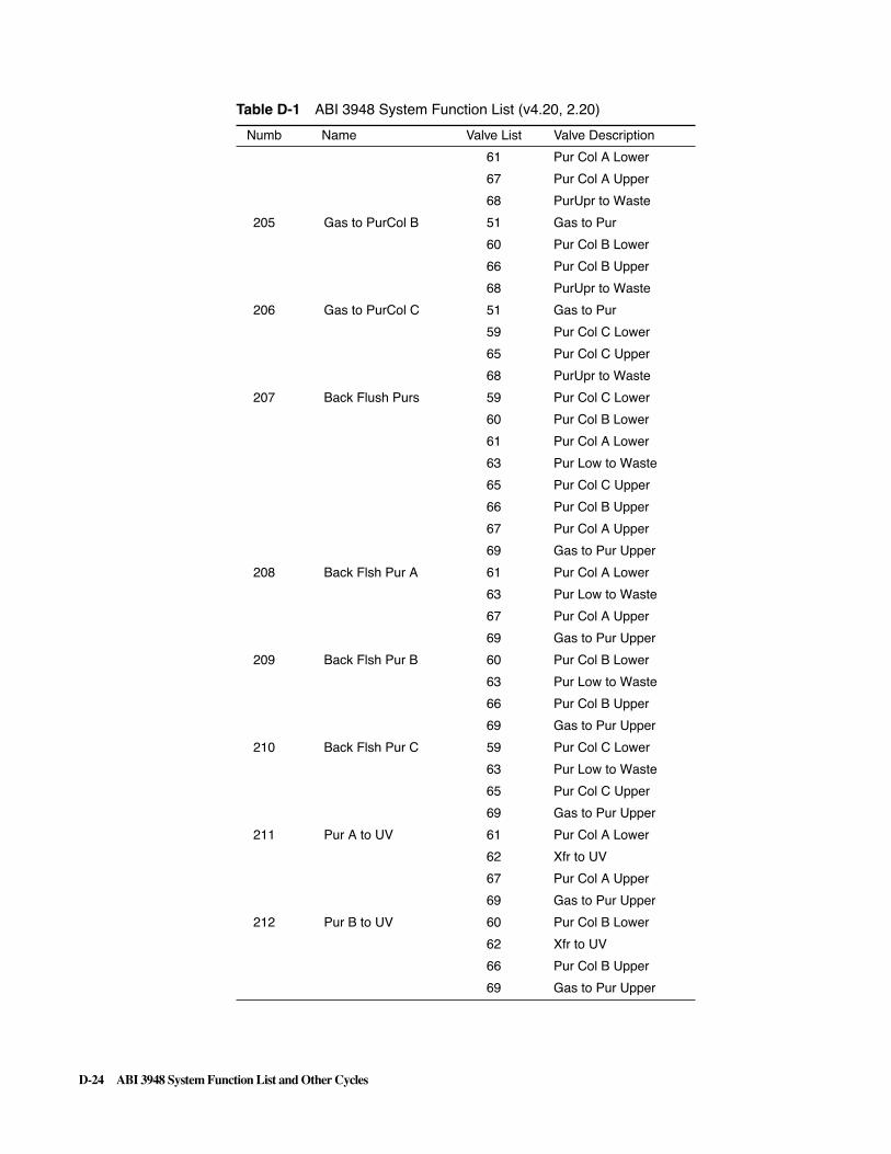
D-24 ABI 3948 System Function List and Other Cycles
61 Pur Col A Lower
67 Pur Col A Upper
68 PurUpr to Waste
205 Gas to PurCol B 51 Gas to Pur
60 Pur Col B Lower
66 Pur Col B Upper
68 PurUpr to Waste
206 Gas to PurCol C 51 Gas to Pur
59 Pur Col C Lower
65 Pur Col C Upper
68 PurUpr to Waste
207 Back Flush Purs 59 Pur Col C Lower
60 Pur Col B Lower
61 Pur Col A Lower
63 Pur Low to Waste
65 Pur Col C Upper
66 Pur Col B Upper
67 Pur Col A Upper
69 Gas to Pur Upper
208 Back Flsh Pur A 61 Pur Col A Lower
63 Pur Low to Waste
67 Pur Col A Upper
69 Gas to Pur Upper
209 Back Flsh Pur B 60 Pur Col B Lower
63 Pur Low to Waste
66 Pur Col B Upper
69 Gas to Pur Upper
210 Back Flsh Pur C 59 Pur Col C Lower
63 Pur Low to Waste
65 Pur Col C Upper
69 Gas to Pur Upper
211 Pur A to UV 61 Pur Col A Lower
62 Xfr to UV
67 Pur Col A Upper
69 Gas to Pur Upper
212 Pur B to UV 60 Pur Col B Lower
62 Xfr to UV
66 Pur Col B Upper
69 Gas to Pur Upper
Table D-1 ABI 3948 System Function List (v4.20, 2.20)
Numb Name Valve List Valve Description

ABI 3948 System Function List and Other Cycles D-25
D 3948 Function List and Other Cycles
Table D-1 ABI 3948 System Function List (v4.20, 2.20)
Numb Name Valve List Valve Description
213 Pur C to UV 59 Pur Col C Lower
62 Xfr to UV
65 Pur Col C Upper
69 Gas to Pur Upper
214 H2O to UV 56 H2O to Pur
62 Xfr to UV
215 Xfer UV to SC 77 UV Lower
78 Gas to UV
216 UV Reading
217 Flush UV toWaste 77 UV Lower
78 Gas to UV
79 UV to Waste
218 PurLowBlk Flush 51 Gas to Pur
63 Pur Low to Waste
219 PurUprBlk Flush 68 PurUpr to Waste
69 Gas to Pur Upper
220 Pur Vent 59 Pur Col C Lower
60 Pur Col B Lower
61 Pur Col A Lower
63 Pur Low to Waste
221 DepUprBlk Flush 44 Gas to Dep Upper
50 DepUpr to Waste
222 SC Block Flush 51 Gas to Pur
62 Xfr to UV
223 Set UV Scale Adjusts ODU calculation with a scaling factor expressed as a percent.
224 Pur Gas to Dep 49 Xfer from Dep
50 DepUpr to Waste
51 Gas to Pur
58 Xfer from Dep
225 Pur ACN to Dep 49 Xfer from Dep
50 DepUpr to Waste
52 ACN to Pur
58 Xfer from Dep
226 Pur H2O to Dep 49 Xfer from Dep
50 DepUpr to Waste
56 H2O to Pur
58 Xfer from Dep
227 *User Fxn 227 *
228 *User Fxn 228 *

D-26 ABI 3948 System Function List and Other Cycles
229 End Row SCP/123
230 Go Sub On Fail
231 Syn Jaw Open
232 Syn Jaw Close 2 Gas to Syn
13 Syn Col C Lower
14 Syn Col B Lower
15 Syn Col A Lower
16 Xfer to SynLow
28 Gas to Syn Upper
233 Clv Jaw Open
234 Clv Jaw Close 29 Gas to Clv Lower
39 Xfer Clv to Dep
75 Gas to Clv Upper
235 Pur Jaw Open
236 Pur Jaw Close 49 Xfer from Dep
51 Gas to Pur
58 Xfer from Dep
59 Pur Col C Lower
60 Pur Col B Lower
61 Pur Col A Lower
69 Gas to Pur Upper
237 Open All Jaws
238 Close All Jaws
239 TurnTable Home
240 TurnTable Next
241 TurnTable Prev
242 SC Waste Puts needle over sample vials.
243 SC Home Sends tray to “home” position.
244 SC Next Sends tray to the next position.
245 SC Open Sends tray to the front.
246 SC Close Sends tray to correct position according to index.
247 SC Needle Up
248 SC Needle Down
249 Relay 1 On
250 Relay 1 Off
251 Relay 1 Pulse
252 Relay 2 On
253 Relay 2 Off
254 Relay 2 Pulse
255 Fan On
256 Fan Off
Table D-1 ABI 3948 System Function List (v4.20, 2.20)

ABI 3948 System Function List and Other Cycles D-27
257 Heater On
258 Heater Off
259 Wait
260 Set Coil Temp
261 Wait Coil Temp Cycle waits for heater to reach temp. in the Misc field, cycle resumes when temp. is reached or when step times out. On timeout, temp. reached before going on is reported in the status window (Monitor Chemistry).
262 Tggle Vlves On Turns single valve ON until Tggle Vlves Off function is used.
263 Tggle Vlves Off Used to turn OFF single valves activated by the Tggle Vlves On function.
264 SC Prev Sends tray to the previous position according to index.
265 Set Rmp Fxn Sns These functions are used to set parameters which help define the behavior of the ramping functions. See 265 Set Rmp Fxn Sns, et al in Appendix A.
266 Set Rmp Fxn Trp
267 Set Rmp Fxn Chk
268 Set Rmp Fxn Dly
269 Send Message These two parameters are used to send a message as specified in the MISC field. See 269 Send Message/ 270Comment in Appendix A.
270 Comment
271 Begin of Cycle These functions serve only to mark the beginning and ending steps of a cycle procedure.
272 End of Cycle
273 Begin Loop These functions mark the beginning and ending boundaries of a block of steps to be executed repeatedly.
274 End Loop
275 Start Here “cycle entry” - First Synthesis cycle skips to this step to begin.
276 Exit DMT On This step executes only on the last synthesis cycle of any given column. See the discussion in Appendix A.
277 If Pur Col A Execute steps to Else or Endif if Col A is active, otherwise skips steps.
278 If Pur Col B Execute steps to Else or Endif if Col B is active, otherwise skips steps.
279 If Pur Col C Execute steps to Else or Endif if Col C is active, otherwise skips steps.
280 Else Execute when previous If statement condition is false;
281 Endif End of If statement.
282 Select Pur Cols Picks columns that require purification (no Crude).
283 Select Act Cols Picks active columns, crude or pure.
Table D-1 ABI 3948 System Function List (v4.20, 2.20)

D-28 ABI 3948 System Function List and Other Cycles
284 Clv Wants Depro Cleavage module waits on Pur flag reset.
285 Pure Owns Depro (I) - sets flag at the beginning to “Pur.” Flag indicates that purification “owns” deprotection coils.
286 Clv Owns Depro (O) - resets flag at the end to “Not Pur ” - releases deprotection coils to cleavage.
287 Go Sub
288 Return Sub
289 Sub Label
290 Goto End
291 If Any Act Cols Executes steps to nearest Else or Endif, only if there are columns purifying - deactivates all non-purifying columns.
292 Go Sub A Do subroutine (Go Sub A) only if column is active. Deactivates other columns until Return Sub.
293 Go Sub B Do subroutine (Go Sub B) only if column is active. Deactivates other columns until Return Sub.
294 Go Sub C Do subroutine (Go Sub C) only if column is active. Deactivates other columns until Return Sub.
295 If First Cycle
296 If Last Cycle
297 If Crude Col A
298 If Crude Col B
299 If Crude Col C
300 Engage All Cols
301 Set Pres Reg 1
302 Set Pres Reg 2
303 Set Pres Reg 3
304 Set Pres Reg 4
305 Set Pres Reg 5
306 Set Pres Reg 6
307 Set Pres Reg 7
308 Set Pres Reg 8
309 Set Pres Reg 9
310 Set Pres Reg 10
311 Set Press RegAll
312 Press Reg On
313 Press Reg Off
314 Pres Reg AllOn
Table D-1 ABI 3948 System Function List (v4.20, 2.20)

ABI 3948 System Function List and Other Cycles D-29
D 3948 Function List and Other Cycles
Table D-1 ABI 3948 System Function List (v4.20, 2.20)
Numb Name Valve List Valve Description
315 Pres Reg AllOff
316 If Cyc Greater
317 Save Reg Pres
318 Restore RegPres
319 Revive Act Cols
320 Check Snsr Cal Checks all sensor calibrations. “Wet readings” are at least 2X “dry readings.”
321 CalibrateGas Sns Takes a dry sensor calibration reading.
322 CalibrateLiqSns Takes a wet sensor calibration reading.
323 Calib AllGasSns
324 Calib AllLiqSns
325 Jaw Test Time Used during instrument assembly.
326 Pres SynJaws 24 Syn Col C Upper
25 Syn Col B Upper
26 Syn Col A Upper
28 Gas to Syn Upper
327 Pres ClvJaws 75 Gas to Clv Upper
328 Pres PurJaws 51 Gas to Pur
59 Pur Col C Lower
60 Pur Col B Lower
61 Pur Col A Lower
329 Begin Leak Test
330 End Leak Test
331 NMI to Cols 13 Syn Col C Lower
14 Syn Col B Lower
15 Syn Col A Lower
16 Xfr to SynLow
17 NMI
22 SynUpr to Waste
24 Syn Col C Upper
25 Syn Col B Upper
26 Syn Col A Upper
332 NMI to Col A 15 Syn Col A Lower
16 Xfr to SynLow
17 NMI
22 SynUpr to Waste
26 Syn Col A Upper
333 NMI to Col B 14 Syn Col B Lower
16 Xfr to SynLow
17 NMI
22 SynUpr to Waste

D-30 ABI 3948 System Function List and Other Cycles
25 Syn Col B Upper
334 NMI to Col C 13 Syn Col C Lower
16 Xfr to SynLow
17 NMI
22 SynUpr to Waste
24 Syn Col C Upper
335 AC20 to Cols 13 Syn Col C Lower
14 Syn Col B Lower
15 Syn Col A Lower
16 Xfr to SynLow
18 Ac20
22 SynUpr to Waste
24 Syn Col C Upper
25 Syn Col B Upper
26 Syn Col A Upper
336 AC20 to Col A 15 Syn Col A Lower
16 Xfr to SynLow
18 Ac20
22 SynUpr to Waste
26 Syn Col A Upper
337 AC20 to Col B 14 Syn Col B Lower
16 Xfr to SynLow
18 Ac20
22 SynUpr to Waste
25 Syn Col B Upper
338 AC20 to Col C 13 Syn Col C Lower
16 Xfr to SynLow
18 Ac20
22 SynUpr to Waste
24 Syn Col C Upper
339 Tet to Test 4 Tetrazole
13 Syn Col C Lower
14 Syn Col B Lower
15 Syn Col A Lower
22 SynUpr to Waste
24 Syn Col C Upper
25 Syn Col B Upper
26 Syn Col A Upper
340 Tet to Test A 4 Tetrazole
15 Syn Col A Lower
22 SynUpr to Waste
Table D-1 ABI 3948 System Function List (v4.20, 2.20)
Numb Name Valve List Valve Description

ABI 3948 System Function List and Other Cycles D-31
26 Syn Col A Upper
341 Tet to Test B 4 Tetrazole
14 Syn Col B Lower
22 SynUpr to Waste
25 Syn Col B Upper
342 Tet to Test C 4 Tetrazole
13 Syn Col C Lower
22 SynUpr to Waste
24 Syn Col C Upper
343 A to Col B 9 "A" Amidite
14 Syn Col B Lower
22 Syn Upr to Waste
25 Syn Col B Upper
344 G to Col B 10 "G" Amidite
14 Syn Col B Lower
22 Syn Upr to Waste
25 Syn Col B Upper
345 C to Col B 11 "C" Amidite
14 Syn Col B Lower
22 Syn Upr to Waste
25 Syn Col B Upper
346 T to Col B 12 "T" Amidite
14 Syn Col B Lower
22 Syn Upr to Waste
25 Syn Col B Upper
347 5 to Col B 5 "5" Amidite
14 Syn Col B Lower
22 Syn Upr to Waste
25 Syn Col B Upper
348 6 to Col B 6 "6" Amidite
14 Syn Col B Lower
22 Syn Upr to Waste
25 Syn Col B Upper
349 7 to Col B 7 "7" Amidite
14 Syn Col B Lower
22 Syn Upr to Waste
25 Syn Col B Upper
350 8 to Col B 8 "8" Amidite
14 Syn Col B Lower
22 Syn Upr to Waste
25 Syn Col B Upper
Table D-1 ABI 3948 System Function List (v4.20, 2.20)
Numb Name Valve List Valve Description

D-32 ABI 3948 System Function List and Other Cycles
351 Fish SynA to SC 3 Xfr from Syn
15 Syn Col A Lower
26 Syn Col A Upper
28 Gas to Syn Upper
30 Xfr to Clv Lower
36 Mfg Test 36
55 Acetic Acid
62 Xfr to UV
352 Flsh SynB to SC 3 Xfr from Syn
14 Syn Col B Lower
25 Syn Col B Upper
28 Gas to Syn Upper
30 Xfr to Clv Lower
36 Mfg Test 36
55 Acetic Acid
62 Xfr to UV
353 Flsh SynC to SC 3 Xfr from Syn
13 Syn Col C Lower
24 Syn Col C Upper
28 Gas to Syn Upper
30 Xfr to Clv Lower
36 Mfg Test 36
55 Acetic Acid
62 Xfr to UV
354 Flsh ClvA to SC 35 Clv Col A Lower
55 Acetic Acid
62 Xfr to UV
75 Gas to Clv Upper
36 Mfg Test 36
355 Flsh ClvB to SC 34 Clv Col B Lower
55 Acetic Acid
62 Xfr to UV
75 Gas to Clv Upper
36 Mfg Test 36
356 Flsh ClvC to SC 33 Clv Col C Lower
55 Acetic Acid
62 Xfr to UVr
75 Gas to Clv Uppe
36 Mfg Test v36
357 ACN to Ammonia 32 Ammonia
38 ACN to Dep Lower
Table D-1 ABI 3948 System Function List (v4.20, 2.20)
Numb Name Valve List Valve Description

ABI 3948 System Function List and Other Cycles D-33
39 Xfr Clv to Dep
358 ACN to TEAA 52 ACN to Pur
53 TEAA
359 ACN to TFA 52 ACN to Pur
54 TFA
360 ACN to H2O(1) 52 ACN to Pur
56 H2O to Pur
361 ACN to H2O(2) 31 H2O to Clv Lower
38 ACN to Dep Lower
39 Xfr Clv to Dep
362 ACN to H2O(3) 38 ACN to Dep Lower
40 Coil A Input
45 H2O to Dep Upper
46 Coil A Exit
363 ACN to 20%ACN 52 ACN to Pur
57 20% ACN
364 ACN to V23 1 ACN to Syn
13 Syn Col C Lower
23 SynUpr to Trityl
24 Syn Col C Upper
365 ACN to V70 NC 52 ACN to Pur
63 Pur Low to Waste
70 Xfr to Trityl
366 ACN to SC NC 52 ACN to Pur
62 Xfr to UVr
367 ACN to V43 1 ACN to Syn
3 Xfr from Syn
30 Xfr to Clv Lower
39 Xfr Clv to Dep
43 Dep Low to Waste
368 ACN to V70 NO 52 ACN to Pur
63 Pur Low to Waste
369 ACN to V79 NC 52 ACN to Pur
62 Xfr to UV
77 UV Lower
79 UV to Waste
370 ACN to DEPRO A 38 ACN to Dep Lower
40 Coil A Input
46 Coil A Exit
50 Dep Upr to Waste
Table D-1 ABI 3948 System Function List (v4.20, 2.20)
Numb Name Valve List Valve Description

D-34 ABI 3948 System Function List and Other Cycles
371 ACN to DEPRO B 38 ACN to Dep Lower
41 Coil B Input
47 Coil B Exit
50 Dep Upr to Waste
372 ACN to DEPRO C 38 ACN to Dep Lower
42 Coil C Input
48 Coil C Exit
50 Dep Upr to Waste
373 R3-UV-SC 51 Gas to Pur
62 Xfr to UV
77 UV Lower
78 Gas to UV
374 R3-UV-Waste 51 Gas to Pur
62 Xfr to UV
77 UV Lower
78 Gas to UV
79 UV to Waste
375 ACN to AcAcid 55 Acetic Acid
52 ACN to Pur
376 Depro Xfer SC 36 Mfg Test v36
37 Gas to De Lower
39 Xfr Clv to Dep
55 Acetic Acid
62 Xfr to UV
377 Flsh DepA to SC 37 Gas to Dep Lower
40 Coil A Input
46 Coil A Exit
49 Xfr from Dep
58 Xfr from Dep
62 Xfr to UV
378 Flsh DepB to SC 37 Gas to Dep Lower
41 Coil B Input
47 Coil B Exit
49 Xfr from Dep
58 Xfr from Dep
62 Xfr to UV
379 Flsh DepC to SC 37 Gas to Dep Lower
42 Coil C lnput
48 Coil C Exit
49 Xfr from Dep
58 Xfr from Dep
Table D-1 ABI 3948 System Function List (v4.20, 2.20)
Numb Name Valve List Valve Description

ABI 3948 System Function List and Other Cycles D-35
62 Xfr to UV
380 *User Fxn 380 *
381 *User Fxn 381 *
382 *User Fxn 382 *
383 *User Fxn 383 *
384 *User Fxn 384 *
385 *User Fxn 385 *
386 *User Fxn 386 *
387 *User Fxn 387 *
388 *User Fxn 388 *
389 *User Fxn 389 *
390 *User Fxn 390 *
391 *User Fxn 391 *
392 *User Fxn 392 *
393 *User Fxn 393 *
394 *User Fxn 394 *
395 Pause Chemistry
396 Time Stamp Report current instrument time with timestamp # to Microphone.
397 Test Valves
398 Depro Test
399 If Test To Do Execute cycle steps to Endif if Test is selected (the test to perform is coded in the Misc field.
400 * Reserved *
401 SynUpr Wet 401
402 SynUprWet A 402
403 SynUprWet B 403
404 SynUprWet C 404
405 SynUpr Wet 405
406 SynUprWet A 406
407 SynUprWet B 407
408 SynUprWet C 408
409 SynUpr Wet 409
410 SynUprWet A 410
411 SynUprWet B 411
412 SynUprWet C 412
413 SynUpr Dry 413
414 SynUprDry A 414
415 SynUprDry B 415
416 SynUprDry C 416
Table D-1 ABI 3948 System Function List (v4.20, 2.20)
Numb Name Valve List Valve Description

D-36 ABI 3948 System Function List and Other Cycles
417 SynMan Wet 417
418 SynManWet A 418
419 SynManWet B 419
420 SynManWet C 420
421 SynMan Wet 421
422 SynManWet A 422
423 SynManWet B 423
424 SynManWet C 424
425 SynMan Wet 425
426 SynManWet A 426
427 SynManWet B 427
428 SynManWet C 428
429 SynLow Wet 429
430 SynLowWet A 430
431 SynLowWet B 431
432 SynLowWet C 432
433 SynLow Dry 433
434 SynLowDry A 434
435 SynLowDry B 435
436 SynLowDry C 436
437 Clv Wet 437
438 Clv Wet A 438
439 Clv Wet B 439
440 Clv Wet C 440
441 Clv Wet 441
442 Clv Wet A 442
443 Clv Wet B 443
444 Clv Wet C 444
445 Clv Dry 445
446 Clv Dry A 446
447 Clv Dry B 447
448 Clv Dry C 448
449 Clv Dry 449
450 Clv Dry A 450
451 Clv Dry B 451
452 Clv Dry C 452
453 Coil Wet 453
454 Coil Wet A 454
455 Coil Wet B 455
Table D-1 ABI 3948 System Function List (v4.20, 2.20)
Numb Name Valve List Valve Description

ABI 3948 System Function List and Other Cycles D-37
D 3948 Function List and Other Cycles
Table D-1 ABI 3948 System Function List (v4.20, 2.20)
Numb Name Valve List Valve Description
456 Coil Wet C 456
457 Coil Dry 457
458 Coil Dry A 458
459 Coil Dry B 459
460 Coil Dry C 460
461 Pur Wet 461
462 Pur Wet A 462
463 Pur Wet B 463
464 Pur Wet C 464
465 Pur Wet 465
466 Pur Wet A 466
467 Pur Wet B 467
468 Pur Wet C 468
469 Pur Wet 469
470 Pur Wet A 470
471 Pur Wet B 471
472 Pur Wet C 472
473 Pur Wet 473
474 Pur Wet A 474
475 Pur Wet B 475
476 Pur Wet C 476
477 Pur Wet 477
478 Pur Wet A 478
479 Pur Wet B 479
480 Pur Wet C 480
481 Pur Dry 481
482 Pur Dry A 482
483 Pur Dry B 483
484 Pur Dry C 484
485 Pur Dry 485
486 Pur Dry A 486
487 Pur Dry B 487
488 Pur Dry C 488
489 UV Wet 489
490 UV Wet 490
491 UV Wet 491
492 UV Wet 492
493 UV Wet 493
494 UV Wet 494
495 UV Wet 495

D-38 ABI 3948 System Function List and Other Cycles
496 UV Wet 496
497 UV Wet 497
498 UV Dry 498
499 UV Dry 499
500 UV Dry 500
Table D-1 ABI 3948 System Function List (v4.20, 2.20)
Numb Name Valve List Valve Description
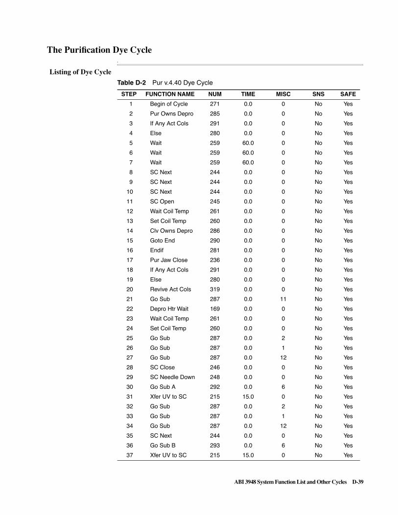
ABI 3948 System Function List and Other Cycles D-39
The Purification Dye CycleA
Listing of Dye Cycle D 3948 Function List and Other Cycles
Table D-2 Pur v.4.40 Dye Cycle
STEP FUNCTION NAME NUM TIME MISC SNS SAFE
1 Begin of Cycle 271 0.0 0 No Yes
2 Pur Owns Depro 285 0.0 0 No Yes
3 If Any Act Cols 291 0.0 0 No Yes
4 Else 280 0.0 0 No Yes
5 Wait 259 60.0 0 No Yes
6 Wait 259 60.0 0 No Yes
7 Wait 259 60.0 0 No Yes
8 SC Next 244 0.0 0 No Yes
9 SC Next 244 0.0 0 No Yes
10 SC Next 244 0.0 0 No Yes
11 SC Open 245 0.0 0 No Yes
12 Wait Coil Temp 261 0.0 0 No Yes
13 Set Coil Temp 260 0.0 0 No Yes
14 Clv Owns Depro 286 0.0 0 No Yes
15 Goto End 290 0.0 0 No Yes
16 Endif 281 0.0 0 No Yes
17 Pur Jaw Close 236 0.0 0 No Yes
18 If Any Act Cols 291 0.0 0 No Yes
19 Else 280 0.0 0 No Yes
20 Revive Act Cols 319 0.0 0 No Yes
21 Go Sub 287 0.0 11 No Yes
22 Depro Htr Wait 169 0.0 0 No Yes
23 Wait Coil Temp 261 0.0 0 No Yes
24 Set Coil Temp 260 0.0 0 No Yes
25 Go Sub 287 0.0 2 No Yes
26 Go Sub 287 0.0 1 No Yes
27 Go Sub 287 0.0 12 No Yes
28 SC Close 246 0.0 0 No Yes
29 SC Needle Down 248 0.0 0 No Yes
30 Go Sub A 292 0.0 6 No Yes
31 Xfer UV to SC 215 15.0 0 No Yes
32 Go Sub 287 0.0 2 No Yes
33 Go Sub 287 0.0 1 No Yes
34 Go Sub 287 0.0 12 No Yes
35 SC Next 244 0.0 0 No Yes
36 Go Sub B 293 0.0 6 No Yes
37 Xfer UV to SC 215 15.0 0 No Yes
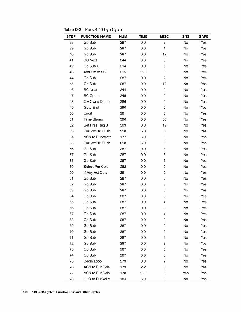
D-40 ABI 3948 System Function List and Other Cycles
38 Go Sub 287 0.0 2 No Yes
39 Go Sub 287 0.0 1 No Yes
40 Go Sub 287 0.0 12 No Yes
41 SC Next 244 0.0 0 No Yes
42 Go Sub C 294 0.0 6 No Yes
43 Xfer UV to SC 215 15.0 0 No Yes
44 Go Sub 287 0.0 2 No Yes
45 Go Sub 287 0.0 12 No Yes
46 SC Next 244 0.0 0 No Yes
47 SC Open 245 0.0 0 No Yes
48 Clv Owns Depro 286 0.0 0 No Yes
49 Goto End 290 0.0 0 No Yes
50 Endif 281 0.0 0 No Yes
51 Time Stamp 396 0.0 30 No Yes
52 Set Pres Reg 3 303 0.0 12 No Yes
53 PurLowBlk Flush 218 5.0 0 No Yes
54 ACN to PurWaste 177 5.0 0 No Yes
55 PurLowBlk Flush 218 5.0 0 No Yes
56 Go Sub 287 0.0 3 No Yes
57 Go Sub 287 0.0 8 No Yes
58 Go Sub 287 0.0 3 No Yes
59 Select Pur Cols 282 0.0 0 No Yes
60 If Any Act Cols 291 0.0 0 No Yes
61 Go Sub 287 0.0 5 No Yes
62 Go Sub 287 0.0 3 No Yes
63 Go Sub 287 0.0 5 No Yes
64 Go Sub 287 0.0 3 No Yes
65 Go Sub 287 0.0 4 No Yes
66 Go Sub 287 0.0 3 No Yes
67 Go Sub 287 0.0 4 No Yes
68 Go Sub 287 0.0 3 No Yes
69 Go Sub 287 0.0 9 No Yes
70 Go Sub 287 0.0 9 No Yes
71 Go Sub 287 0.0 5 No Yes
72 Go Sub 287 0.0 3 No Yes
73 Go Sub 287 0.0 5 No Yes
74 Go Sub 287 0.0 3 No Yes
75 Begin Loop 273 0.0 2 No Yes
76 ACN to Pur Cols 173 2.2 0 No Yes
77 ACN to Pur Cols 173 15.0 0 Yes Yes
78 H2O to PurCol A 184 5.0 0 No Yes
Table D-2 Pur v.4.40 Dye Cycle
STEP FUNCTION NAME NUM TIME MISC SNS SAFE

ABI 3948 System Function List and Other Cycles D-41
79 H2O to PurCol B 185 5.0 0 No Yes
80 H2O to PurCol C 186 5.0 0 No Yes
81 Gas to Pur Cols 203 15.0 0 No Yes
82 Go Sub 287 0.0 3 No Yes
83 End Loop 274 0.0 0 No Yes
84 Go Sub 287 0.0 4 No Yes
85 Go Sub 287 0.0 3 No Yes
86 Set Pres Reg 3 303 0.0 9 No Yes
87 TEAA to Waste 182 5.0 0 No Yes
88 TEAA to PurCols 178 25.0 0 No Yes
89 TEAA to PurCols 178 45.0 0 Yes Yes
90 PurUprBlk Flush 219 2.0 0 No Yes
91 Gas to PurCol A 204 10.0 0 No Yes
92 Gas to PurCol B 205 10.0 0 No Yes
93 Gas to PurCol C 206 10.0 0 No Yes
94 Set Pres Reg 3 303 0.0 12 No Yes
95 Back Flsh Pur A 208 20.0 0 No Yes
96 Back Flsh Pur B 209 20.0 0 No Yes
97 Back Flsh Pur C 210 20.0 0 No Yes
98 Begin Loop 273 0.0 3 No Yes
99 Back Flsh Pur A 208 10.0 0 No Yes
100 Back Flsh Pur B 209 10.0 0 No Yes
101 Back Flsh Pur C 210 10.0 0 No Yes
102 End Loop 274 0.0 0 No Yes
103 Go Sub 287 0.0 10 No Yes
104 Endif 281 0.0 0 No Yes
105 Select Act Cols 283 0.0 0 No Yes
106 Go Sub C 294 0.0 2 No Yes
107 Go Sub 287 0.0 11 No Yes
108 Time Stamp 396 0.0 31 No Yes
109 Depro Htr Wait 169 0.0 0 No Yes
110 Time Stamp 396 0.0 32 No Yes
111 Wait Coil Temp 261 0.0 0 No Yes
112 Set Coil Temp 260 0.0 0 No Yes
113 Time Stamp 396 0.0 33 No Yes
114 Xfer Coil C 168 12.0 1 Yes No
115 Xfer Coil C 168 20.0 0 No No
116 Go Sub B 293 0.0 2 No Yes
117 Xfer Coil B 167 12.0 1 Yes No
118 Xfer Coil B 167 20.0 0 No No
119 Go Sub A 292 0.0 2 No Yes
Table D-2 Pur v.4.40 Dye Cycle
STEP FUNCTION NAME NUM TIME MISC SNS SAFE

D-42 ABI 3948 System Function List and Other Cycles
120 Xfer Coil A 166 12.0 1 Yes No
121 Xfer Coil A 166 20.0 0 No No
122 Time Stamp 396 0.0 34 No Yes
123 Clv Owns Depro 286 0.0 0 No Yes
124 Go Sub 287 0.0 10 No Yes
125 Select Pur Cols 282 0.0 0 No Yes
126 If Any Act Cols 291 0.0 0 No Yes
127 Set Pres Reg 3 303 0.0 9 No Yes
128 Gas to Pur Cols 203 60.0 0 No Yes
129 Set Pres Reg 3 303 0.0 5 No Yes
130 PurLowBlk Flush 218 2.0 0 No Yes
131 Begin Loop 273 0.0 2 No Yes
132 AcAcid to Waste 202 2.0 0 No Yes
133 AcAcid to Purs 198 3.0 0 No Yes
134 AcAcid to Purs 198 30.0 0 Yes Yes
135 Gas to Pur Cols 203 25.0 0 No Yes
136 ACN to PurWaste 177 2.0 0 No Yes
137 PurLowBlk Flush 218 5.0 0 No Yes
138 End Loop 274 0.0 0 No Yes
139 Gas to Pur Cols 203 15.0 0 No Yes
140 Go Sub A 292 0.0 7 No Yes
141 Go Sub B 293 0.0 7 No Yes
142 Go Sub C 294 0.0 7 No Yes
143 Go Sub 287 0.0 4 No No
144 Go Sub 287 0.0 3 No Yes
145 Go Sub 287 0.0 4 No Yes
146 Go Sub 287 0.0 3 No Yes
147 Begin Loop 273 0.0 3 No No
148 Go Sub 287 0.0 4 No No
149 Go Sub 287 0.0 3 No Yes
150 End Loop 274 0.0 0 No No
151 20%ACN to Waste 197 4.0 0 No Yes
152 20%ACN to Purs 193 6.0 0 No Yes
153 20%ACN to Purs 193 15.0 0 Yes Yes
154 Go Sub 287 0.0 10 No Yes
155 Set Pres Reg 3 303 0.0 4 No Yes
156 PurLowBlk Flush 218 2.0 0 No Yes
157 Gas to Pur Cols 203 10.0 0 No Yes
158 Endif 281 0.0 0 No Yes
159 Time Stamp 396 0.0 35 No Yes
160 Select Act Cols 283 0.0 0 No Yes
Table D-2 Pur v.4.40 Dye Cycle
STEP FUNCTION NAME NUM TIME MISC SNS SAFE

ABI 3948 System Function List and Other Cycles D-43
161 Go Sub A 292 0.0 1 No Yes
162 Go Sub A 292 0.0 12 No Yes
163 SC Close 246 0.0 0 No Yes
164 SC Needle Down 248 0.0 0 No Yes
165 Gas to PurCol A 204 7.0 0 No Yes
166 Pur A to UV 211 10.0 3 Yes Yes
167 Pur A to UV 211 20.0 0 No Yes
168 Go Sub A 292 0.0 14 No Yes
169 Go Sub A 292 0.0 15 No Yes
170 Go Sub B 293 0.0 1 No Yes
171 Go Sub B 293 0.0 12 No Yes
172 SC Next 244 0.0 0 No Yes
173 Gas to PurCol B 205 7.0 0 No Yes
174 Pur B to UV 212 10.0 3 Yes Yes
175 Pur B to UV 212 20.0 0 No Yes
176 Go Sub B 293 0.0 14 No Yes
177 Go Sub B 293 0.0 16 No Yes
178 Go Sub C 294 0.0 1 No Yes
179 Go Sub C 294 0.0 12 No Yes
180 SC Next 244 0.0 0 No Yes
181 Gas to PurCol C 206 7.0 0 No Yes
182 Pur C to UV 213 10.0 3 Yes Yes
183 Pur C to UV 213 20.0 0 No Yes
184 Go Sub C 294 0.0 14 No Yes
185 Go Sub C 294 0.0 17 No Yes
186 Go Sub 287 0.0 12 No Yes
187 SC Next 244 0.0 0 No Yes
188 SC Open 245 0.0 0 No Yes
189 Time Stamp 396 0.0 36 No Yes
190 Set Pres Reg 3 303 0.0 5 No Yes
191 Gas to Pur Cols 203 45.0 0 Yes Yes
192 Gas to Pur Cols 203 10.0 0 No Yes
193 Go Sub 287 0.0 3 No Yes
194 Go Sub 287 0.0 8 No Yes
195 Go Sub 287 0.0 3 No Yes
196 Time Stamp 396 0.0 37 No Yes
197 Goto End 290 0.0 0 No Yes
198 Sub Label 289 0.0 1 No Yes
199 Set Pres Reg 3 303 0.0 6 No Yes
200 SC Waste 242 0.0 0 No Yes
201 H2O to PurWaste 187 5.0 0 No Yes
Table D-2 Pur v.4.40 Dye Cycle
STEP FUNCTION NAME NUM TIME MISC SNS SAFE

D-44 ABI 3948 System Function List and Other Cycles
202 H2O to UV 214 5.0 0 No Yes
203 SC Block Flush 222 5.0 0 No Yes
204 Wait 259 10.0 0 No Yes
205 UV Reading 216 2.0 0 No Yes
206 Flsh UV toWaste 217 6.0 0 No Yes
207 H2O to UV 214 1.0 0 No Yes
208 SC Block Flush 222 10.0 0 No Yes
209 Xfer UV to SC 215 10.0 0 No Yes
210 Return Sub 288 0.0 0 No Yes
211 Sub Label 289 0.0 2 No Yes
212 Set Pres Reg 1 301 0.0 12 No Yes
213 Set Pres Reg 3 303 0.0 12 No Yes
214 ACN to PurWaste 177 0.5 0 No Yes
215 PurLowBlk Flush 218 3.0 0 No Yes
216 Pur Xfer Rinse 171 2.0 0 No Yes
217 Pur Xfer Flush 172 15.0 0 No Yes
218 Set Pres Reg 1 301 0.0 8 No Yes
219 DepLowBlk Flush 153 2.0 0 No No
220 Return Sub 288 0.0 0 No No
221 Sub Label 289 0.0 3 No Yes
222 Set Pres Reg 3 303 0.0 12 No Yes
223 Back Flush Purs 207 6.0 0 No Yes
224 Back Flush Purs 207 45.0 0 Yes Yes
225 Back Flsh Pur A 208 6.0 0 No Yes
226 Back Flsh Pur B 209 6.0 0 No Yes
227 Back Flsh Pur C 210 6.0 0 No Yes
228 Begin Loop 273 0.0 2 No Yes
229 Gas to Pur Cols 203 1.0 0 No Yes
230 Back Flush Purs 207 4.0 0 No Yes
231 End Loop 274 0.0 0 No Yes
232 Return Sub 288 0.0 0 No Yes
233 Sub Label 289 0.0 4 No Yes
234 Set Pres Reg 3 303 0.0 9 No Yes
235 H2O to Pur Cols 183 3.0 0 No Yes
236 H2O to Pur Cols 183 15.0 0 Yes Yes
237 Gas to Pur Cols 203 15.0 0 Yes Yes
238 Gas to Pur Cols 203 6.0 0 No Yes
239 Return Sub 288 0.0 0 No Yes
240 Sub Label 289 0.0 5 No Yes
241 Set Pres Reg 3 303 0.0 4 No Yes
242 ACN to Pur Cols 173 4.0 0 No Yes
Table D-2 Pur v.4.40 Dye Cycle
STEP FUNCTION NAME NUM TIME MISC SNS SAFE

ABI 3948 System Function List and Other Cycles D-45
243 ACN to Pur Cols 173 15.0 0 Yes Yes
244 Gas to Pur Cols 203 15.0 0 Yes Yes
245 Gas to Pur Cols 203 6.0 0 No Yes
246 Return Sub 288 0.0 0 No Yes
247 Sub Label 289 0.0 6 No Yes
248 Crude A to UV 135 12.0 1 Yes Yes
249 Crude A to UV 135 20.0 0 No Yes
250 Crude B to UV 136 12.0 1 Yes Yes
251 Crude B to UV 136 20.0 0 No Yes
252 Crude C to UV 137 12.0 1 Yes Yes
253 Crude C to UV 137 20.0 0 No Yes
254 Return Sub 288 0.0 0 No Yes
255 Sub Label 289 0.0 7 No Yes
256 Set Pres Reg 3 303 0.0 12 No Yes
257 ACN to PurWaste 177 2.0 0 No Yes
258 PurLowBlk Flush 218 5.0 0 No Yes
259 Set Pres Reg 3 303 0.0 6 No Yes
260 Back Flush Purs 207 15.0 0 No Yes
261 Back Flush Purs 207 45.0 3 Yes Yes
262 Set Pres Reg 3 303 0.0 12 No Yes
263 Back Flush Purs 207 15.0 0 No Yes
264 Return Sub 288 0.0 0 No Yes
265 Sub Label 289 0.0 8 No Yes
266 Set Pres Reg 3 303 0.0 6 No Yes
267 ACN to Pur Cols 173 4.0 0 No Yes
268 ACN to Pur Cols 173 15.0 0 Yes Yes
269 Gas to Pur Cols 203 15.0 0 Yes Yes
270 Gas to Pur Cols 203 3.0 0 No Yes
271 Set Pres Reg 3 303 0.0 8 No Yes
272 Begin Loop 273 0.0 2 No Yes
273 H2O to Pur Cols 183 4.0 0 No Yes
274 H2O to Pur Cols 183 15.0 0 Yes Yes
275 Gas to Pur Cols 203 15.0 0 Yes Yes
276 Gas to Pur Cols 203 3.0 0 No Yes
277 End Loop 274 0.0 0 No Yes
278 Set Pres Reg 3 303 0.0 12 No Yes
279 Gas to Pur Cols 203 8.0 0 No Yes
280 Return Sub 288 0.0 0 No Yes
281 Sub Label 289 0.0 9 No Yes
282 Set Pres Reg 3 303 0.0 4 No Yes
283 PurLowBlk Flush 218 2.0 0 No Yes
Table D-2 Pur v.4.40 Dye Cycle
STEP FUNCTION NAME NUM TIME MISC SNS SAFE

D-46 ABI 3948 System Function List and Other Cycles
284 TFA to Pur Cols 188 6.0 0 No Yes
285 TFA to Pur Cols 188 25.0 0 Yes Yes
286 Wait 259 15.0 0 No Yes
287 Begin Loop 273 0.0 2 No Yes
288 TFA to PurCol A 189 1.0 999 No Yes
289 TFA to PurCol B 190 1.0 999 No Yes
290 TFA to PurCol C 191 1.0 999 No Yes
291 Wait 259 15.0 0 No Yes
292 End Loop 274 0.0 0 No Yes
293 Begin Loop 273 0.0 6 No Yes
294 Gas to PurCol A 204 0.6 0 No Yes
295 Gas to PurCol B 205 0.6 0 No Yes
296 Gas to PurCol C 206 0.6 0 No Yes
297 Pur Vent 220 2.0 0 No Yes
298 Wait 259 23.0 0 No Yes
299 End Loop 274 0.0 0 No Yes
300 Set Pres Reg 3 303 0.0 10 No Yes
301 Tggle Vlves On 262 0.0 70 No Yes
302 Back Flsh Pur A 208 12.0 0 No Yes
303 Back Flsh Pur B 209 12.0 0 No Yes
304 Back Flsh Pur C 210 12.0 0 No Yes
305 Set Pres Reg 3 303 0.0 12 No Yes
306 Back Flsh Pur A 208 10.0 0 No Yes
307 Back Flsh Pur B 209 10.0 0 No Yes
308 Back Flsh Pur C 210 10.0 0 No Yes
309 Gas to Pur Cols 203 2.0 0 No Yes
310 Back Flush Purs 207 8.0 0 No Yes
311 Tggle Vlves Off 263 0.0 70 No Yes
312 Return Sub 288 0.0 0 No Yes
313 Sub Label 289 0.0 10 No Yes
314 H2O to PurWaste 187 1.0 0 No Yes
315 Set Pres Reg 3 303 0.0 12 No Yes
316 PurLowBlk Flush 218 6.0 0 No Yes
317 Return Sub 288 0.0 0 No Yes
318 Sub Label 289 0.0 11 No Yes
319 Set Rmp Fxn Sns 265 0.0 10 No Yes
320 Set Rmp Fxn Trp 266 0.0 5 No Yes
321 Set Rmp Fxn Chk 267 0.0 5 No Yes
322 Set Rmp Fxn Dly 268 0.0 60 No Yes
323 Return Sub 288 0.0 0 No Yes
324 Sub Label 289 0.0 12 No Yes
Table D-2 Pur v.4.40 Dye Cycle
STEP FUNCTION NAME NUM TIME MISC SNS SAFE
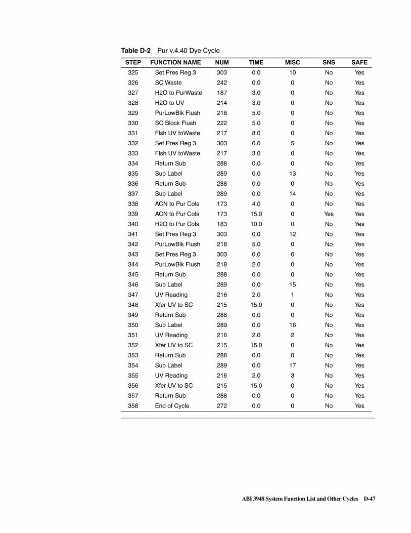
ABI 3948 System Function List and Other Cycles D-47
325 Set Pres Reg 3 303 0.0 10 No Yes
326 SC Waste 242 0.0 0 No Yes
327 H2O to PurWaste 187 3.0 0 No Yes
328 H2O to UV 214 3.0 0 No Yes
329 PurLowBlk Flush 218 5.0 0 No Yes
330 SC Block Flush 222 5.0 0 No Yes
331 Flsh UV toWaste 217 8.0 0 No Yes
332 Set Pres Reg 3 303 0.0 5 No Yes
333 Flsh UV toWaste 217 3.0 0 No Yes
334 Return Sub 288 0.0 0 No Yes
335 Sub Label 289 0.0 13 No Yes
336 Return Sub 288 0.0 0 No Yes
337 Sub Label 289 0.0 14 No Yes
338 ACN to Pur Cols 173 4.0 0 No Yes
339 ACN to Pur Cols 173 15.0 0 Yes Yes
340 H2O to Pur Cols 183 10.0 0 No Yes
341 Set Pres Reg 3 303 0.0 12 No Yes
342 PurLowBlk Flush 218 5.0 0 No Yes
343 Set Pres Reg 3 303 0.0 6 No Yes
344 PurLowBlk Flush 218 2.0 0 No Yes
345 Return Sub 288 0.0 0 No Yes
346 Sub Label 289 0.0 15 No Yes
347 UV Reading 216 2.0 1 No Yes
348 Xfer UV to SC 215 15.0 0 No Yes
349 Return Sub 288 0.0 0 No Yes
350 Sub Label 289 0.0 16 No Yes
351 UV Reading 216 2.0 2 No Yes
352 Xfer UV to SC 215 15.0 0 No Yes
353 Return Sub 288 0.0 0 No Yes
354 Sub Label 289 0.0 17 No Yes
355 UV Reading 216 2.0 3 No Yes
356 Xfer UV to SC 215 15.0 0 No Yes
357 Return Sub 288 0.0 0 No Yes
358 End of Cycle 272 0.0 0 No Yes
Table D-2 Pur v.4.40 Dye Cycle
STEP FUNCTION NAME NUM TIME MISC SNS SAFE

D-48 ABI 3948 System Function List and Other Cycles
The Purification Biotin Cycle
Listing of BiotinCycle
Table D-3 Pur v4.40 Biotin Cycle
STEP FUNCTION NAME NUM TIME MISC SNS SAFE
1 Begin of Cycle 271 0.0 0 No Yes
2 Pur Owns Depro 285 0.0 0 No Yes
3 If Any Act Cols 291 0.0 0 No Yes
4 Else 280 0.0 0 No Yes
5 Wait 259 60.0 0 No Yes
6 Wait 259 60.0 0 No Yes
7 Wait 259 60.0 0 No Yes
8 SC Next 244 0.0 0 No Yes
9 SC Next 244 0.0 0 No Yes
10 SC Next 244 0.0 0 No Yes
11 SC Open 245 0.0 0 No Yes
12 Wait Coil Temp 261 0.0 0 No Yes
13 Set Coil Temp 260 0.0 0 No Yes
14 Clv Owns Depro 286 0.0 0 No Yes
15 Goto End 290 0.0 0 No Yes
16 Endif 281 0.0 0 No Yes
17 Pur Jaw Close 236 0.0 0 No Yes
18 If Any Act Cols 291 0.0 0 No Yes
19 Else 280 0.0 0 No Yes
20 Revive Act Cols 319 0.0 0 No Yes
21 Go Sub 287 0.0 11 No Yes
22 Depro Htr Wait 169 0.0 0 No Yes
23 Wait Coil Temp 261 0.0 0 No Yes
24 Set Coil Temp 260 0.0 0 No Yes
25 Go Sub 287 0.0 2 No Yes
26 Go Sub 287 0.0 1 No Yes
27 Go Sub 287 0.0 12 No Yes
28 SC Close 246 0.0 0 No Yes
29 SC Needle Down 248 0.0 0 No Yes
30 Go Sub A 292 0.0 6 No Yes
31 Xfer UV to SC 215 15.0 0 No Yes
32 Go Sub 287 0.0 2 No Yes
33 Go Sub 287 0.0 1 No Yes
34 Go Sub 287 0.0 12 No Yes
35 SC Next 244 0.0 0 No Yes
36 Go Sub B 293 0.0 6 No Yes
37 Xfer UV to SC 215 15.0 0 No Yes

ABI 3948 System Function List and Other Cycles D-49
38 Go Sub 287 0.0 2 No Yes
39 Go Sub 287 0.0 1 No Yes
40 Go Sub 287 0.0 12 No Yes
41 SC Next 244 0.0 0 No Yes
42 Go Sub C 294 0.0 6 No Yes
43 Xfer UV to SC 215 15.0 0 No Yes
44 Go Sub 287 0.0 2 No Yes
45 Go Sub 287 0.0 12 No Yes
46 SC Next 244 0.0 0 No Yes
47 SC Open 245 0.0 0 No Yes
48 Clv Owns Depro 286 0.0 0 No Yes
49 Goto End 290 0.0 0 No Yes
50 Endif 281 0.0 0 No Yes
51 Time Stamp 396 0.0 30 No Yes
52 Set Pres Reg 3 303 0.0 12 No Yes
53 PurLowBlk Flush 218 5.0 0 No Yes
54 ACN to PurWaste 177 5.0 0 No Yes
55 PurLowBlk Flush 218 5.0 0 No Yes
56 Go Sub 287 0.0 3 No Yes
57 Go Sub 287 0.0 8 No Yes
58 Go Sub 287 0.0 3 No Yes
59 Select Pur Cols 282 0.0 0 No Yes
60 If Any Act Cols 291 0.0 0 No Yes
61 Go Sub 287 0.0 5 No Yes
62 Go Sub 287 0.0 3 No Yes
63 Go Sub 287 0.0 5 No Yes
64 Go Sub 287 0.0 3 No Yes
65 Go Sub 287 0.0 4 No Yes
66 Go Sub 287 0.0 3 No Yes
67 Go Sub 287 0.0 4 No Yes
68 Go Sub 287 0.0 3 No Yes
69 Go Sub 287 0.0 9 No Yes
70 Go Sub 287 0.0 9 No Yes
71 Go Sub 287 0.0 5 No Yes
72 Go Sub 287 0.0 3 No Yes
73 Go Sub 287 0.0 5 No Yes
74 Go Sub 287 0.0 3 No Yes
75 Begin Loop 273 0.0 2 No Yes
76 ACN to Pur Cols 173 2.2 0 No Yes
77 ACN to Pur Cols 173 15.0 0 Yes Yes
78 H2O to PurCol A 184 5.0 0 No Yes
Table D-3 Pur v4.40 Biotin Cycle
STEP FUNCTION NAME NUM TIME MISC SNS SAFE

D-50 ABI 3948 System Function List and Other Cycles
79 H2O to PurCol B 185 5.0 0 No Yes
80 H2O to PurCol C 186 5.0 0 No Yes
81 Gas to Pur Cols 203 15.0 0 No Yes
82 Go Sub 287 0.0 3 No Yes
83 End Loop 274 0.0 0 No Yes
84 Go Sub 287 0.0 4 No Yes
85 Go Sub 287 0.0 3 No Yes
86 Set Pres Reg 3 303 0.0 9 No Yes
87 TEAA to Waste 182 5.0 0 No Yes
88 TEAA to PurCols 178 25.0 0 No Yes
89 TEAA to PurCols 178 45.0 0 Yes Yes
90 PurUprBlk Flush 219 2.0 0 No Yes
91 Gas to PurCol A 204 10.0 0 No Yes
92 Gas to PurCol B 205 10.0 0 No Yes
93 Gas to PurCol C 206 10.0 0 No Yes
94 Set Pres Reg 3 303 0.0 12 No Yes
95 Back Flsh Pur A 208 20.0 0 No Yes
96 Back Flsh Pur B 209 20.0 0 No Yes
97 Back Flsh Pur C 210 20.0 0 No Yes
98 Begin Loop 273 0.0 3 No Yes
99 Back Flsh Pur A 208 10.0 0 No Yes
100 Back Flsh Pur B 209 10.0 0 No Yes
101 Back Flsh Pur C 210 10.0 0 No Yes
102 End Loop 274 0.0 0 No Yes
103 Go Sub 287 0.0 10 No Yes
104 Endif 281 0.0 0 No Yes
105 Select Act Cols 283 0.0 0 No Yes
106 Go Sub C 294 0.0 2 No Yes
107 Go Sub 287 0.0 11 No Yes
108 Time Stamp 396 0.0 31 No Yes
109 Depro Htr Wait 169 0.0 0 No Yes
110 Time Stamp 396 0.0 32 No Yes
111 Wait Coil Temp 261 0.0 0 No Yes
112 Set Coil Temp 260 0.0 0 No Yes
113 Time Stamp 396 0.0 33 No Yes
114 Xfer Coil C 168 12.0 1 Yes No
115 Xfer Coil C 168 20.0 0 No No
116 Go Sub B 293 0.0 2 No Yes
117 Xfer Coil B 167 12.0 1 Yes No
118 Xfer Coil B 167 20.0 0 No No
119 Go Sub A 292 0.0 2 No Yes
Table D-3 Pur v4.40 Biotin Cycle
STEP FUNCTION NAME NUM TIME MISC SNS SAFE

ABI 3948 System Function List and Other Cycles D-51
120 Xfer Coil A 166 12.0 1 Yes No
121 Xfer Coil A 166 20.0 0 No No
122 Time Stamp 396 0.0 34 No Yes
123 Clv Owns Depro 286 0.0 0 No Yes
124 Go Sub 287 0.0 10 No Yes
125 Select Pur Cols 282 0.0 0 No Yes
126 If Any Act Cols 291 0.0 0 No Yes
127 Set Pres Reg 3 303 0.0 9 No Yes
128 Gas to Pur Cols 203 60.0 0 No Yes
129 Set Pres Reg 3 303 0.0 5 No Yes
130 PurLowBlk Flush 218 2.0 0 No Yes
131 Begin Loop 273 0.0 2 No Yes
132 AcAcid to Waste 202 2.0 0 No Yes
133 AcAcid to Purs 198 3.0 0 No Yes
134 AcAcid to Purs 198 30.0 0 Yes Yes
135 Gas to Pur Cols 203 25.0 0 No Yes
136 ACN to PurWaste 177 2.0 0 No Yes
137 PurLowBlk Flush 218 5.0 0 No Yes
138 End Loop 274 0.0 0 No Yes
139 Gas to Pur Cols 203 15.0 0 No Yes
140 Go Sub A 292 0.0 7 No Yes
141 Go Sub B 293 0.0 7 No Yes
142 Go Sub C 294 0.0 7 No Yes
143 Go Sub 287 0.0 4 No No
144 Go Sub 287 0.0 3 No Yes
145 Go Sub 287 0.0 4 No Yes
146 Go Sub 287 0.0 3 No Yes
147 Begin Loop 273 0.0 5 No Yes
148 Go Sub 287 0.0 9 No Yes
149 End Loop 274 0.0 0 No Yes
150 Begin Loop 273 0.0 3 No No
151 Go Sub 287 0.0 4 No No
152 Go Sub 287 0.0 3 No Yes
153 End Loop 274 0.0 0 No No
154 20%ACN to Waste 197 4.0 0 No Yes
155 20%ACN to Purs 193 6.0 0 No Yes
156 20%ACN to Purs 193 15.0 0 Yes Yes
157 Go Sub 287 0.0 10 No Yes
158 Set Pres Reg 3 303 0.0 4 No Yes
159 PurLowBlk Flush 218 2.0 0 No Yes
160 Gas to Pur Cols 203 10.0 0 No Yes
Table D-3 Pur v4.40 Biotin Cycle
STEP FUNCTION NAME NUM TIME MISC SNS SAFE

D-52 ABI 3948 System Function List and Other Cycles
161 Endif 281 0.0 0 No Yes
162 Time Stamp 396 0.0 35 No Yes
163 Select Act Cols 283 0.0 0 No Yes
164 Go Sub A 292 0.0 1 No Yes
165 Go Sub A 292 0.0 12 No Yes
166 SC Close 246 0.0 0 No Yes
167 SC Needle Down 248 0.0 0 No Yes
168 Gas to PurCol A 204 7.0 0 No Yes
169 Pur A to UV 211 10.0 3 Yes Yes
170 Pur A to UV 211 20.0 0 No Yes
171 Go Sub A 292 0.0 14 No Yes
172 Go Sub A 292 0.0 15 No Yes
173 Go Sub B 293 0.0 1 No Yes
174 Go Sub B 293 0.0 12 No Yes
175 SC Next 244 0.0 0 No Yes
176 Gas to PurCol B 205 7.0 0 No Yes
177 Pur B to UV 212 10.0 3 Yes Yes
178 Pur B to UV 212 20.0 0 No Yes
179 Go Sub B 293 0.0 14 No Yes
180 Go Sub B 293 0.0 16 No Yes
181 Go Sub C 294 0.0 1 No Yes
182 Go Sub C 294 0.0 12 No Yes
183 SC Next 244 0.0 0 No Yes
184 Gas to PurCol C 206 7.0 0 No Yes
185 Pur C to UV 213 10.0 3 Yes Yes
186 Pur C to UV 213 20.0 0 No Yes
187 Go Sub C 294 0.0 14 No Yes
188 Go Sub C 294 0.0 17 No Yes
189 Go Sub 287 0.0 12 No Yes
190 SC Next 244 0.0 0 No Yes
191 SC Open 245 0.0 0 No Yes
192 Time Stamp 396 0.0 36 No Yes
193 Set Pres Reg 3 303 0.0 5 No Yes
194 Gas to Pur Cols 203 45.0 0 Yes Yes
195 Gas to Pur Cols 203 10.0 0 No Yes
196 Go Sub 287 0.0 3 No Yes
197 Go Sub 287 0.0 8 No Yes
198 Go Sub 287 0.0 3 No Yes
199 Time Stamp 396 0.0 37 No Yes
200 Goto End 290 0.0 0 No Yes
201 Sub Label 289 0.0 1 No Yes
Table D-3 Pur v4.40 Biotin Cycle
STEP FUNCTION NAME NUM TIME MISC SNS SAFE

ABI 3948 System Function List and Other Cycles D-53
202 Set Pres Reg 3 303 0.0 6 No Yes
203 SC Waste 242 0.0 0 No Yes
204 H2O to PurWaste 187 5.0 0 No Yes
205 H2O to UV 214 5.0 0 No Yes
206 SC Block Flush 222 5.0 0 No Yes
207 Wait 259 10.0 0 No Yes
208 UV Reading 216 2.0 0 No Yes
209 Flsh UV toWaste 217 6.0 0 No Yes
210 H2O to UV 214 1.0 0 No Yes
211 SC Block Flush 222 10.0 0 No Yes
212 Xfer UV to SC 215 10.0 0 No Yes
213 Return Sub 288 0.0 0 No Yes
214 Sub Label 289 0.0 2 No Yes
215 Set Pres Reg 1 301 0.0 12 No Yes
216 Set Pres Reg 3 303 0.0 12 No Yes
217 ACN to PurWaste 177 0.5 0 No Yes
218 PurLowBlk Flush 218 3.0 0 No Yes
219 Pur Xfer Rinse 171 2.0 0 No Yes
220 Pur Xfer Flush 172 15.0 0 No Yes
221 Set Pres Reg 1 301 0.0 8 No Yes
222 DepLowBlk Flush 153 2.0 0 No No
223 Return Sub 288 0.0 0 No No
224 Sub Label 289 0.0 3 No Yes
225 Set Pres Reg 3 303 0.0 12 No Yes
226 Back Flush Purs 207 6.0 0 No Yes
227 Back Flush Purs 207 45.0 0 Yes Yes
228 Back Flsh Pur A 208 6.0 0 No Yes
229 Back Flsh Pur B 209 6.0 0 No Yes
230 Back Flsh Pur C 210 6.0 0 No Yes
231 Begin Loop 273 0.0 2 No Yes
232 Gas to Pur Cols 203 1.0 0 No Yes
233 Back Flush Purs 207 4.0 0 No Yes
234 End Loop 274 0.0 0 No Yes
235 Return Sub 288 0.0 0 No Yes
236 Sub Label 289 0.0 4 No Yes
237 Set Pres Reg 3 303 0.0 9 No Yes
238 H2O to Pur Cols 183 3.0 0 No Yes
239 H2O to Pur Cols 183 15.0 0 Yes Yes
240 Gas to Pur Cols 203 15.0 0 Yes Yes
241 Gas to Pur Cols 203 6.0 0 No Yes
242 Return Sub 288 0.0 0 No Yes
Table D-3 Pur v4.40 Biotin Cycle
STEP FUNCTION NAME NUM TIME MISC SNS SAFE

D-54 ABI 3948 System Function List and Other Cycles
243 Sub Label 289 0.0 5 No Yes
244 Set Pres Reg 3 303 0.0 4 No Yes
245 ACN to Pur Cols 173 4.0 0 No Yes
246 ACN to Pur Cols 173 15.0 0 Yes Yes
247 Gas to Pur Cols 203 15.0 0 Yes Yes
248 Gas to Pur Cols 203 6.0 0 No Yes
249 Return Sub 288 0.0 0 No Yes
250 Sub Label 289 0.0 6 No Yes
251 Crude A to UV 135 12.0 1 Yes Yes
252 Crude A to UV 135 20.0 0 No Yes
253 Crude B to UV 136 12.0 1 Yes Yes
254 Crude B to UV 136 20.0 0 No Yes
255 Crude C to UV 137 12.0 1 Yes Yes
256 Crude C to UV 137 20.0 0 No Yes
257 Return Sub 288 0.0 0 No Yes
258 Sub Label 289 0.0 7 No Yes
259 Set Pres Reg 3 303 0.0 12 No Yes
260 ACN to PurWaste 177 2.0 0 No Yes
261 PurLowBlk Flush 218 5.0 0 No Yes
262 Set Pres Reg 3 303 0.0 6 No Yes
263 Back Flush Purs 207 15.0 0 No Yes
264 Back Flush Purs 207 45.0 3 Yes Yes
265 Set Pres Reg 3 303 0.0 12 No Yes
266 Back Flush Purs 207 15.0 0 No Yes
267 Return Sub 288 0.0 0 No Yes
268 Sub Label 289 0.0 8 No Yes
269 Set Pres Reg 3 303 0.0 6 No Yes
270 ACN to Pur Cols 173 4.0 0 No Yes
271 ACN to Pur Cols 173 15.0 0 Yes Yes
272 Gas to Pur Cols 203 15.0 0 Yes Yes
273 Gas to Pur Cols 203 3.0 0 No Yes
274 Set Pres Reg 3 303 0.0 8 No Yes
275 Begin Loop 273 0.0 2 No Yes
276 H2O to Pur Cols 183 4.0 0 No Yes
277 H2O to Pur Cols 183 15.0 0 Yes Yes
278 Gas to Pur Cols 203 15.0 0 Yes Yes
279 Gas to Pur Cols 203 3.0 0 No Yes
280 End Loop 274 0.0 0 No Yes
281 Set Pres Reg 3 303 0.0 12 No Yes
282 Gas to Pur Cols 203 8.0 0 No Yes
283 Return Sub 288 0.0 0 No Yes
Table D-3 Pur v4.40 Biotin Cycle
STEP FUNCTION NAME NUM TIME MISC SNS SAFE

ABI 3948 System Function List and Other Cycles D-55
284 Sub Label 289 0.0 9 No Yes
285 Set Pres Reg 3 303 0.0 4 No Yes
286 PurLowBlk Flush 218 2.0 0 No Yes
287 TFA to Pur Cols 188 6.0 0 No Yes
288 TFA to Pur Cols 188 25.0 0 Yes Yes
289 Wait 259 15.0 0 No Yes
290 Begin Loop 273 0.0 2 No Yes
291 TFA to PurCol A 189 1.0 999 No Yes
292 TFA to PurCol B 190 1.0 999 No Yes
293 TFA to PurCol C 191 1.0 999 No Yes
294 Wait 259 15.0 0 No Yes
295 End Loop 274 0.0 0 No Yes
296 Begin Loop 273 0.0 6 No Yes
297 Gas to PurCol A 204 0.6 0 No Yes
298 Gas to PurCol B 205 0.6 0 No Yes
299 Gas to PurCol C 206 0.6 0 No Yes
300 Pur Vent 220 2.0 0 No Yes
301 Wait 259 23.0 0 No Yes
302 End Loop 274 0.0 0 No Yes
303 Set Pres Reg 3 303 0.0 10 No Yes
304 Tggle Vlves On 262 0.0 70 No Yes
305 Back Flsh Pur A 208 12.0 0 No Yes
306 Back Flsh Pur B 209 12.0 0 No Yes
307 Back Flsh Pur C 210 12.0 0 No Yes
308 Set Pres Reg 3 303 0.0 12 No Yes
309 Back Flsh Pur A 208 10.0 0 No Yes
310 Back Flsh Pur B 209 10.0 0 No Yes
311 Back Flsh Pur C 210 10.0 0 No Yes
312 Gas to Pur Cols 203 2.0 0 No Yes
313 Back Flush Purs 207 8.0 0 No Yes
314 Tggle Vlves Off 263 0.0 70 No Yes
315 Return Sub 288 0.0 0 No Yes
316 Sub Label 289 0.0 10 No Yes
317 H2O to PurWaste 187 1.0 0 No Yes
318 Set Pres Reg 3 303 0.0 12 No Yes
319 PurLowBlk Flush 218 6.0 0 No Yes
320 Return Sub 288 0.0 0 No Yes
321 Sub Label 289 0.0 11 No Yes
322 Set Rmp Fxn Sns 265 0.0 10 No Yes
323 Set Rmp Fxn Trp 266 0.0 5 No Yes
324 Set Rmp Fxn Chk 267 0.0 5 No Yes
Table D-3 Pur v4.40 Biotin Cycle
STEP FUNCTION NAME NUM TIME MISC SNS SAFE

D-56 ABI 3948 System Function List and Other Cycles
325 Set Rmp Fxn Dly 268 0.0 60 No Yes
326 Return Sub 288 0.0 0 No Yes
327 Sub Label 289 0.0 12 No Yes
328 Set Pres Reg 3 303 0.0 10 No Yes
329 SC Waste 242 0.0 0 No Yes
330 H2O to PurWaste 187 3.0 0 No Yes
331 H2O to UV 214 3.0 0 No Yes
332 PurLowBlk Flush 218 5.0 0 No Yes
333 SC Block Flush 222 5.0 0 No Yes
334 Flsh UV toWaste 217 8.0 0 No Yes
335 Set Pres Reg 3 303 0.0 5 No Yes
336 Flsh UV toWaste 217 3.0 0 No Yes
337 Return Sub 288 0.0 0 No Yes
338 Sub Label 289 0.0 13 No Yes
339 Return Sub 288 0.0 0 No Yes
340 Sub Label 289 0.0 14 No Yes
341 ACN to Pur Cols 173 4.0 0 No Yes
342 ACN to Pur Cols 173 15.0 0 Yes Yes
343 H2O to Pur Cols 183 10.0 0 No Yes
344 Set Pres Reg 3 303 0.0 12 No Yes
345 PurLowBlk Flush 218 5.0 0 No Yes
346 Set Pres Reg 3 303 0.0 6 No Yes
347 PurLowBlk Flush 218 2.0 0 No Yes
348 Return Sub 288 0.0 0 No Yes
349 Sub Label 289 0.0 15 No Yes
350 UV Reading 216 2.0 1 No Yes
351 Xfer UV to SC 215 15.0 0 No Yes
352 Return Sub 288 0.0 0 No Yes
353 Sub Label 289 0.0 16 No Yes
354 UV Reading 216 2.0 2 No Yes
355 Xfer UV to SC 215 15.0 0 No Yes
356 Return Sub 288 0.0 0 No Yes
357 Sub Label 289 0.0 17 No Yes
358 UV Reading 216 2.0 3 No Yes
359 Xfer UV to SC 215 15.0 0 No Yes
360 Return Sub 288 0.0 0 No Yes
361 End of Cycle 272 0.0 0 No Yes
Table D-3 Pur v4.40 Biotin Cycle
STEP FUNCTION NAME NUM TIME MISC SNS SAFE

Instrument Plumbing Diagram E-1
Instrument Plumbing Diagram E E


Limited Warranty Statement F-1
Limited Warranty Statement F
Applied Biosystems warrants to the customer that, for a period ending on the earlier of two (2) years from the completion of installation or twenty-seven (27) months from the date of shipment to the customer (the “Warranty Period”), the ABI 3948 Nucleic Acid Synthesis and Purification System purchased by the customer (the “Instrument”) will be free from defects in material and workmanship, and will perform in accordance with the specifications set forth in the ABI 3948 System Data Sheet (the “Specifications”).
During the Warranty Period, if the Instrument's hardware becomes damaged or contaminated or if the Instrument otherwise fails to meet the Specifications, Applied Biosystems will repair or replace the Instrument so that it meets the Specifications, at Applied Biosystems expense. However, if the Instrument's valves or reagent lines become damaged or contaminated, or if the chemical performance of the Instrument otherwise deteriorates due to solvents and/or reagents other than those supplied or expressly recommended by Applied Biosystems, Applied Biosystems will return the Instrument to Specification at the customer’s request and at the customer's expense. After this service is performed, coverage of the parts repaired or replaced will be restored thereafter for the remainder of the Warranty Period.
This Warranty does not extend to any Instrument or part which has been (a) the subject of an accident, misuse, or neglect, (b) modified or repaired by a party other than Applied Biosystems, or (c) used in a manner not in accordance with the instructions contained in the Reference Manual or the Instrument User's Manual. This Warranty does not cover the customer-installable accessories or customer-installable consumable parts for the Instrument that are listed in the Reference Manual or Instrument User's Manual. Those items may have their own separate warranties.
Applied Biosystems obligation under this Warranty is limited to repairs or replacements that Applied Biosystems deems necessary to correct those failures by the Instrument to meet the Specifications of which Applied Biosystems is notified prior to expiration of the Warranty Period. All repairs and replacements under this Warranty will be performed by Applied Biosystems on site at the Customer's location at Applied Biosystems sole expense.
No agent, employee, or representative of Applied Biosystems has any authority to bind Applied Biosystems to any affirmation, representation, or warranty concerning the Instrument that is not contained in Applied Biosystemss printed product literature or this Warranty Statement. Any such affirmation. representation or warranty made by any agent, employee, or representative of Applied Biosystems will not be binding on Applied Biosystems.
Applied Biosystems shall not be liable for any incidental, special, or consequential loss, damage or expense directly or indirectly arising from the purchase or use of the Instrument. Applied Biosystems makes no warranty whatsoever with regard to
F

F-2 Limited Warranty Statement
products or parts furnished by third parties; such products or parts will be subject to the warranties, if any, of their respective manufacturers.
This Warranty is limited to the original site of installation and is not transferable.
THIS WARRANTY IS THE SOLE AND EXCLUSIVE WARRANTY AS TO THE INSTRUMENT AND IS IN LIEU OF ANY OTHER EXPRESS OR IMPLIED WARRANTIES, INCLUDING, WITHOUT LIMITATION, ANY IMPL!ED WARRANTY OF MERCHANTABILITY OR FITNESS FOR A PARTICULAR PURPOSE AND OF ANY OTHER OBLIGATION ON THE PART OF APPLIED BIOSYSTEMS.

Index-1
Numerics3' phosphorus 3-34X12 configuration rack
standard white 2-22
AABI 3948
calculation of concentration 3-25
computer controlled 2-6Abort
defined 1-4Abort command
definition 4-21procedure 4-22
absorbancereported in ODUs (Optical Density
Units) and picomoles 2-5acetonitrile
wash before detritylation 3-9Alternative Chemistries 3-28aminomethyl linker
attached to support material 3-4ammonium hydroxide, use in
cleavage 3-16application memory setting
default 4-10Applications
used to create Multi-Order files 4-41
Apply Button 6-14Automation
Chemistry Processes 2-4Auto-res OK 0.01 PSI
parameter 4-28Auto-Resume feature
Instrument Preferences commandauto-resume feature 4-27
Auto-resume Minutes parameter 4-28
BB+ Tet Calibration
contents of view 6-8base deprotection
guidelines 3-17Baseline absorbance
setting by the system 3-24Beer’s Law 3-22Begin and End Procedures
defined 1-4
benzoylprotection group 3-7
Block functionsgas flush, pressurization, and
rinse A-22priming delivery lines A-21priming for Cleavage
Columns A-21priming for Purification
Columns A-22Bottle change functions A-20bottle procedure
editing 6-22
CCalculation
of concentration (pmol/µL) 3-25Capping
characteristics 3-13process 3-13
capping 3-13–??, 3-13–3-14by acetylation 3-13highly recommended 3-13needed because coupling is not
always quantitative 3-13reactive chains not affected by
capping 3-13Change Name command
definition 4-21procedure 4-26
Change Passwords commanddefinition 4-21
Check Illegal Values parameter 4-29chemical delivery system
pressure driven 2-3Chemistries
alternative 3-28Chemistry
of choice 3-7progress during a run 5-12solid phase synthesis 3-3
chemistryprogress of 5-12
Chemistry Panesdescription of 5-12
Chemistry Processesautomation 2-4First Four 2-4
Chemistry protocolsdescription C-2
Chemistry reactionsdetails of four reactions 3-6
Chemistry Stages A-3Cleavage
module 2-4process of 2-15
cleavage and deprotection 3-16–3-17
removal of protecting groups 3-17
Cleavage Cycle parameter 5-9Cleavage functions
delivery to cleavage columns A-17
gas flushes and pressurization A-17
oligonucleotide transfer A-18water delivery to deprotection
coil A-18cleavage jaw sensors 5-16Cleavage module
components 2-7location and description 2-15
Cleavage reaction 3-16Close All Synth Orders
command 4-3definition 4-3
Close command 4-3Coil Cool Secs (261) parameter 4-28collection needle
waste bottles 2-22Column turntable
purpose of 2-7Command-Key commands 4-4Command-key equivalents (hot keys)
Edit menu 4-17File menu 4-4
Commands and capabilitiesoverview 4-1
Communication Viewinitial database window 5-6
concentrated aqueous ammonium hydroxide
used to cleave the oligonucleotide 2-4
controlleralso fills out Synthesis
Orders 2-3real time control 2-3
Copy from Button 6-14Coupling
characteristics 3-12
Index

Index-2
coupling 3-11–3-12, ??–3-12effect of excess of
phosphoramidite 3-12mixed sequence probes 3-12Nucleophilic attack by
tetrazole 3-12reactivity order for cyanoethyl
phosphoramidites 3-12Creating
Synthesis Orders 4-38Creating a User Function
procedure 6-5Criteria
for converting ODU to mass or concentration 3-22
Critical messages C-42crude oligonucleotides
with the 5´ trityl group either on or off 2-4
Current date and timewhere displayed 5-15
cuvette 2-20cyanoethyl
protecting group 3-8Cyanoethyl phosphoramidite
four functional groups 3-8cyanoethyl phosphoramidites
reactivity order 3-12cycle
definition of A-3Cycle and Procedure Pop-Up Menus
Edit views 6-13
Ddenaturing media 3-20Deprotect Mins (169)
parameter 4-28Deprotect Temp (170)
parameter 4-28Deprotection
module 2-4process of 2-17time and temperature 2-4
deprotectionbase 3-17phosphate 3-16
deprotection coil sensors 5-17Deprotection module
components 2-7, 2-16location 2-16
Depurinationpurines susceptable to 3-9
depurinationminimization of 3-10
Detritylationchemistry process 3-9
diisopropylamino functional group 3-8
dimethoxytrityl groupremoval 3-5
DNA productsdescription of elution 2-4
DNA purification 3-20DNA storage
period of stability 3-27DNA Synthesis Cycle
four steps 3-3
EEdit Begin Procedure View 6-20Edit Bottle Procedure View 6-22
purpose of view 6-22Edit Cleavage Cycle View
purpose of view 6-18Edit commands
Find Same 4-18Read Selection 4-17Replace command 4-18
Edit Cycle and Procedure interfaceButtons 6-14entry fields 6-16interface elements 6-12
Edit End Procedure Viewediting 6-21
Edit Function Viewscrollable lists 6-4
Edit menu ??–4-19list of commands 4-17
Edit Purification Cycle Viewpurpose of view 6-19
edit sequence 4-18Edit Synthesis Cycle View
purpose of 6-17Edit Views, all
same general layout 6-12Electromechanical and electrical
drivers 2-6embedded software 2-6End Row on Jaw Leak
parameter 4-29End sequence
with A, B, C or T on the 3´ end 4-7
entering sequencesas mixed bases 4-39
Entry fieldsEdit Cycle and Procedure
interface 6-16Execute Button 6-14Exercising Manual Control
of a FunctionManual Control View
exercising control of afunction 6-4
exocyclic amines 3-5Export command 4-15export files
names and icons 4-15Export Procedure icons 4-15
Export Sequence commanddefinition 4-3
Ext. Coefficient 5, 6, 7, and 8description 4-28
Extinction coefficientmajor contributors to 3-22
Extinction coefficientsfor fluorescent dye labels 3-26
Ffailure sequences 3-13File commands
Import/Export 4-15Open 4-8Save a Copy In 4-13Send Copy to Synthesizer 4-14Send to Synthesizer 4-13
File menu 4-3–??list of commands 4-3list of tasks 4-3
final detritylationa trityl flush 3-9
Find command 4-18Find Same command
procedure 4-18Find/Find Same commands
definition 4-17Flow path
ACN to Column A (illustration) A-9
flowcell1 cm pathlength quartz 3-23
Function names A-7functional groups
on phosphoramidites 3-8Functions
three fundamental types A-7Time and Misc field entries A-7tracing flow paths A-8
functionsprinting 6-5
Functions in cyclesdescription C-2
GGas pressure sensors/sensor
drivers 2-6General activity messages C-40Generate Run File command 4-16
definition 4-3Generating Synthesis Orders
from Multi-Order files 4-42
HHardware
types of 2-7Hierarchical messages C-43high throughput 2-4

Index-3
IImport command 4-15Import Sequence command
definition 4-3Import/Export
discussion 4-15Importing and Exporting Sequences
Synthesis Orders 4-39Importing Synthesis Orders
process 5-21initial Chemistry Pane view 5-12Insert Button 6-15instrument control
real time 2-3Instrument Dip Switches
Instrument PreferencesInst rument Dip Swi tches
parameters 4-29Instrument Messages C-40Instrument plumbing diagram E-1Instrument Preferences command
definition 4-21purpose of 4-27Setup Variables 4-28
Instrument Test Viewactivating tests 6-8tests performed 6-7
Interruptdefined 1-4
Interrupt command 4-22definition 4-21
iodine reagentin oxidation 3-15
isobutyrylprotection group 3-7
JJaw Leak Test
in PSI parameter 4-28Jaw mechanism
illustration and detailed description 2-11
purpose of 2-7
Kkey terms
table of 1-4
LLabel View
information in individual labels 4-36
Label View informationin the five columns 4-36
Leak OK 0.01 PSIparameter 4-28
Limited warranty statement F-1Liquid sensors 2-6
conventions 5-16
list of open windows 4-30Log Dry Sensor Fxns
parameter 4-29Low pressure mercury lamp 3-23low-pressure mercury lamp
(P/N) 2-20
MMan Cont Jaw Testing
parameter 4-29Manual Control
Creating a User Function 6-5exercises valve functions A-10printing functions 6-5
Manual Control Viewviewing a function valve list 6-4
manual volumes, twopurposes of 1-1
Maxam-Gilbert sequencingreference to 3-9
Method of synthesisPhosphoramidite 2-3
Microphone-only messages C-42Misc (Miscellaneous) Procedures View
purpose of view 6-23Miscellaneous hardware
functions A-24Miscellaneous Procedures C-37mixed base entry 4-39Mixed sequence probes
synthesis of 3-12Mnfg. Jaw Test Mode
parameter 4-29modify
sequence 4-18module 2-4Molar extinction coefficent 3-22Monitor Chemistry View
interface information 5-11sequence pane
description 5-13Status and System
Message 5-13three chemistry panes 5-12
Monitor Chemistry viewdescription of three chemistry
panes 5-12general description 5-11using information 5-14
Monitor Instrument Viewother
parameters/conditions 5-18
Monitor Run Viewgeneral information 5-19types of information
provided 5-19monitoring
valves 5-15monitoring chemistry 5-14
Monomersother than standard
phosphoramidite 3-28Multi-Order files
types of applications used to create 4-41
Nname
changing the synthesizer 4-26New Synthesizer Order command
definition 4-3NMI reagent
in capping 3-13No Flow To Open Jaws
parameter 4-29non-valve hardware functions
pressure regulating A-23nucleosides
phosphoramidite 3-7Nucleotide 3´-hydroxyl
attachment to support 3-4
OODU
as a measure of concentration 3-22
criteria for converting to mass or concentration 3-22
definition 3-22ODU as the Unit of Measure
definitions which apply 3-22ODU Measurement
optimum measurement criteria 3-22
oligonucleotide productiondescription of process 2-3
oligonucleotide quantitation 3-22oligonucleotide yield
automatic measurement 3-23oligonucleotides
methods of purification 3-20storage for later use 3-27types to avoid storing 3-27
OneStep columncontains the 3´-terminal
nucleoside 2-4illustration and detailed
description 2-9moves between three
modules 2-4three of four chemistry processes
occur within 2-4OneStep column turntable
illustration and detailed description 2-10
OneStep™ Columnfour types 2-7
OneStep™ column 2-3

Index-4
Open command 4-8definition 4-3
Open Synthesizer command 4-3definition 4-3
Opening an Oligo Labels window for printing
alternate way 4-35oxidation 3-15Oxidation after capping
importance of 3-15Oxidation reaction 3-15
PPAGE and HPLC
use for purification 3-20Page Setup command
definition 4-3Parallel and serial User Functions
use together A-13Pause After
defined 1-4Pause After Command
programming a pause 4-23Pause After command
definition 4-21Pause On Jaw Leak
parameter 4-29Pause On Sensor Fail
parameter 4-29Phosphate deprotection 3-16phosphoramidite method of
oligonucleotide synthesischaracteristics 3-7
Phosphoramidite method of synthesisoverview 3-6
phosphoramidite method of synthesis 2-3
phosphoramidite nucleosidesFigure 3-7
Phosphoramidite nucleotidesfunctional groups 3-8structures and molecular
weights 3-7phosphoramidite sensors 5-17phosphoramidites
function groups 3-8phosphoramidites and tetrazole
delivered simultaneouslyl during coupling 3-11
polystyreneused as solid support for DNA
synthesis 3-4Polystyrene support
highly cross-linked 3-3Power Fail View
purpose of 6-6Pressure regulating functions A-23Pressure Regulation and Control
(PRC) modulecharacteristics 2-12
Pressure Regulation and Control module (PRC)
purpose of 2-7Printing labels from RunFiles
alternate way 4-35information in individual
labels 4-36procedure
definition of A-3types of A-3
Proceduresbottle change (Manual
Dilution) C-36End C-34miscellaneous C-37phosphoramidite
autodilution C-36Start Up C-32
proceduresfor beginning synthesis C-32
protecting groupsremoval 3-17
protection groups 3-7Protocol
defined 1-4Protocol Name parameter 5-9Purification 2-4
characteristics of 3-20other methods 3-20process of 2-19
Purification and quantitation functionscollecting and quantitating
samples A-19delivery of reagents to purification
columns/UV detector A-18
rinsing and flushing deprotection columns A-19
Purification biotin cyclelisting D-48
purification coil sensors 5-17Purification Cycle parameter 5-10Purification dye cycle
listing D-39Purification module
components 2-7location and description 2-18
Purification stages 3-20purification step
omitting 3-5purified oligonucleotides
must be synthesized with the 5´ trityl group on 2-4
QQuantitation
general description 2-5Quantitation module 2-20
components 2-7
quantitation of oligonucleotidesby UV spectroscopy 3-22
RRacks
two types of 2-22racks
outside dimensions 2-22reaction column chamber
OneStep column 2-3reactive chains
still trityl blocked 3-13Read Selection command 4-17,
4-40definition 4-17procedure 4-17
red rackoptional 2-22
Reference manuallisting of chapter contents 1-2
Refrigerated storagein solution 3-27
Regular reports messages C-40Replace 4-18Replace command
procedure 4-18Replace/Replace Same commands
definition 4-17Reserved parameter 4-29Resume command 4-22
definition 4-21Run Protocol View 5-10
Cleavage Cycle parameter 5-9Protocol Name parameter 5-9Synthesis Cycle parameter 5-9used to create protocols 5-9
Run Setup Viewassigning chemistry 5-25autoSorting 5-25description of Open Dialog box
buttons 5-22information provided for a selected
sequence 5-24list of Menus and Buttons 5-8list of tasks performed
accessing 5-7selecting orders for the next
run 5-23RunFiles
list of types of information 4-32
SSafe/Sensor Buttons 6-15Sample collection
general description 2-5unattended collection of 48 DNA
samples 2-5

Index-5
Sample Collection modulecomponents 2-7components and
illustration 2-21needle assembly 2-21
Sample Labeling featureprocedure 4-33
Sample rackscharacteristics 2-22
sample vialssample volume 2-5
Save & Reopen command 4-3definition 4-3
Save a Copy In Commanddiscussion 4-13
Save a Copy In command 4-13definition 4-3
Save and Reopen commanddiscussion 4-14
Save As command 4-3definition 4-3
Save command 4-3definition 4-3
Scaling factor 3-24Select All command
definition 4-17Send Copy to Synthesizer
command 4-14definition 4-3
Send to Synthesizer command 4-3definition 4-3types of files sent 4-13
Sensor User Function namescomponents of A-12
Sensor-Controlled User Function example A-14
Sensorsgeneral characteristic A-11location of A-11names and locations A-13retries A-12use of parallel with serial Sensor
User Functions A-13septum sheet
purpose of 2-5where located 2-5
sequenceimport
export 4-15Sequence entry
Synthesis Orders 4-6sequence modification 4-18sequence pane description
Monitor Chemistry View 5-13Setup Choices
Instrument PreferencesSetup Choices 4-29
Setup Variables 4-28Show Clipboard command
definition 4-17
Solid supportcharacteristics 3-3
Solid–phase synthesis chemistry 3-3Special functions
overview of B-2Standard Cleavage/Deprotection Cycle
listing C-12summary C-9
Standard Purification Cyclelisting C-23summary C-18
Standard Synthesis Cyclesummary C-3
Standard Synthesis Cycle listing C-5Status and System Messages
Monitor Chemistry View 5-13Storage
frozen in 20% acetonitrile 3-27guidelines 3-27of crudes 3-27other liquid media 3-27
string substitutions 4-18succinate ester bond 3-4Support
characteristics 3-4support material
highly cross-linked polystyrene 3-4
Synchronize Clocks command 4-24definition 4-21
Synthesismodule 2-4process 3-3process of 2-14
synthesiscompletion of 3-5
Synthesis column functionsflushing and back flushing A-16
Synthesis Cycleconcluding steps 3-5
Synthesis Cycle parameter 5-9synthesis jaw sensors 5-16synthesis manifold sensors 5-17Synthesis Module
components 2-7Synthesis module
location and description 2-13Synthesis Order
sequence entry 4-39Synthesis Order command
description of fields 4-5types of information 4-5
Synthesis Order informationprovided for a selected
sequence 5-24
Synthesis Ordersactions after Sequence
Entry 4-40importing and exporting
sequences 4-39information contained
within 4-38ways of creating 4-38
Synthesis scaledescription C-2
Synthesis valve functions A-15Synthesis Window
editing 5-1Synthesizer Commands
list of definitions 4-21Synthesizer commands
Synchronize Clocks commandprocedure 4-24
Synthesizer menu 4-21–??Abort 4-22Change Name 4-26Interrupt 4-22Resume 4-22Synchronize clocks 4-24
Synthesizer Windowaccessing by password 5-6general information 5-4keyboard shortcuts 5-5list of views 5-4
Synthesizer windowlist of views 4-11
Synthesizer Window viewslist of 4-11
System Functions A-7System messages C-38
categories of messages C-39critical messages C-42hierarchical messages C-43message conventions C-39Microphone-only
messages C-42regular reports messages C-40types of messages C-38
TTCA
in detritylation 3-9three stations
concurrent use of A-4trichloroacetic acid 3-9
for DMT removal 3-5trityl
protecting group 3-8trityl group
as handle for purification 3-5Turntable control functions A-23turntable positions (A, B, C) 5-16types of runs
pre-programmed or custom 2-3Types of storage 2-6

Index-6
UUse Sounds command
definition 4-17User 4x12 Tube Rack
parameter 4-29User bulletins
contents and purpose 1-4User cycles
description C-2User Functions A-7
general description A-12User functions A-20UV detection system
description 2-20UV detector sensor 5-17UV flowcell
illustration 3-23UV hardware 3-23UV scaling factor 3-24UV spectroscopy 3-22UV-light source
254 nm 2-20
VValve Functions
creating your own A-10types of A-10uses of A-10
Valve functionslist of function categories A-15
valve statusoff or on 5-15
Valveslist of valves A-5
vial septumchemically inert 2-5
Viewing a function valve list 6-4
Wwaste bottles
location of bottles for collection needle rinse 2-22
wetted componentschemically inert 2-11
Window menu 4-30description 4-30
XXfer From Coil (261) parameter 4-28Xfer Into Coil (260) parameter 4-28


Headquarters850 Lincoln Centre DriveFoster City, CA 94404 USA Phone: +1 650.638.5800 Toll Free: +1 800.345.5224 Fax: +1 650.638.5884
Worldwide Sales OfficesApplied Biosystems vast distribution and service network, composed of highly trained support and applications personnel, reaches into 150 countries on six continents. For international office locations, please call our local office or refer to our web site at www.appliedbiosystems.com.
www.appliedbiosystems.com
Applied Biosystems is committed to providing the world’s leading technology and information for life scientists.
Printed in the USA, 04/2011Part Number 4303111C
Top Related