Reference Guide to Treatment Technologies for Mining ... · REFERENCE GUIDE. to Treatment...
94
REFERENCE GUIDE to Treatment Technologies for Mining-Influenced Water U.S. Environmental Protection Agency Office of Superfund Remediation and Technology Innovation March 2014 EPA 542-R-14-001
-
Upload
nguyentuong -
Category
Documents
-
view
216 -
download
2
Transcript of Reference Guide to Treatment Technologies for Mining ... · REFERENCE GUIDE. to Treatment...

REFERENCE GUIDE to Treatment Technologies for
Mining-Influenced Water
U.S. Environmental Protection Agency Office of Superfund Remediation and Technology Innovation
March 2014EPA 542-R-14-001

March 2014 2
Contents
Contents .......................................................................................................................................... 2
Acronyms and Abbreviations ......................................................................................................... 5
Notice and Disclaimer..................................................................................................................... 7
Introduction ..................................................................................................................................... 8
Methodology ................................................................................................................................... 9
Passive Technologies
Technology: Anoxic Limestone Drains ........................................................................................ 11
Technology: Successive Alkalinity Producing Systems (SAPS).................................................. 16
Technology: Aluminator© ............................................................................................................ 19
Technology: Constructed Wetlands .............................................................................................. 23
Technology: Biochemical Reactors .............................................................................................. 27
Technology: Phytotechnologies .................................................................................................... 31
Technology: Permeable Reactive Barriers.................................................................................... 34
Active Technologies
Technology: Fluidized Bed Reactor ............................................................................................. 38
Technology: Reverse Osmosis ...................................................................................................... 42
Technology: Zero Valent Iron ...................................................................................................... 47
Technology: Rotating Cylinder Treatment Systems ..................................................................... 51
Technology: Ferrihydrite Adsorption ........................................................................................... 56
Technology: Electrocoagulation ................................................................................................... 59
Technology: Ion Exchange ........................................................................................................... 62
Technology: Biological Reduction ............................................................................................... 66
Technology: Ceramic Microfiltration ........................................................................................... 70
Appendix A. Summary of Treatment Technologies ..................................................................... 73
List of References ......................................................................................................................... 89

March 2014 3
Figures
Figure 1: ALD Cross-Section ....................................................................................................... 11
Figure 2: Anoxic Limestone Drain Outflow at the Midwestern Reclamation Site, Pike County,
Indiana........................................................................................................................................... 12
Figure 3: Cross-section Diagram of a Typical SAPS ................................................................... 16
Figure 4. Cross-Section of Typical Aluminator© System ............................................................ 20
Figure 5. Vertical Flow and Horizontal Flow Constructed Wetlands .......................................... 23
Figure 6. Cross-Section of a Constructed Wetland Design .......................................................... 24
Figure 7. Example of Passive BCR System .................................................................................. 27
Figure 8: PRB Diagram ................................................................................................................ 34
Figure 9: Example FBR System Design ....................................................................................... 38
Figure 10: Envirogen’s FBR Model EFB-14 ................................................................................ 39
Figure 11: Diagram of Simplified Reverse Osmosis Technology ................................................ 42
Figure 12: Two Reverse Osmosis Treatment Racks at the BCWTP ............................................ 44
Figure 13. ZVI Process Diagram Using Column Setup with Steel Wool ..................................... 48
Figure 14: RCTS Unit at the Soudan Mine ................................................................................... 51
Figure 15: Schematic of the 2005 Rio Tinto Water Treatment, with Two RCTS Units .............. 53
Figure 16: RCTS at the Rio Tinto Mine ....................................................................................... 55
Figure 17. Ferrihydrite Adsorption Flow Diagram ....................................................................... 57
Figure 18: Ion Exchange Process Flow Diagram ......................................................................... 62
Figure 19: In-Mine Ion Exchange Treatment System at the Soudan Mine .................................. 65
Figure 20: ABMet® Flow Diagram .............................................................................................. 67
Figure 21: Ceramic Microfiltration System at the Upper Blackfoot Mining Complex, Montana 70
Figure 22: Ceramic Microfiltration Cross-Flow Diagram ............................................................ 71
Tables
Table 1: Examples of ALD Implementation ................................................................................. 13
Table 2. Examples of ALD Efficiencies ....................................................................................... 15
Table 3: SAPS Removal Efficiencies at Summitville Mine ......................................................... 18
Table 4: Removal Efficiencies at Five SAPS Sites ...................................................................... 18
Table 5: Buckeye Reclamation Landfill and Little Mill Creek System Results ........................... 21

March 2014 4
Table 6. Treatment Efficiencies Observed for Constructed Wetlands ......................................... 25
Table 7. Maximum Post-Treatment Concentrations at Copper Basin Mining District Constructed
Wetland, 2004 to 2006 .................................................................................................................. 26
Table 8: Common Phytoremediation Mechanisms Used in Mining Remediation ....................... 32
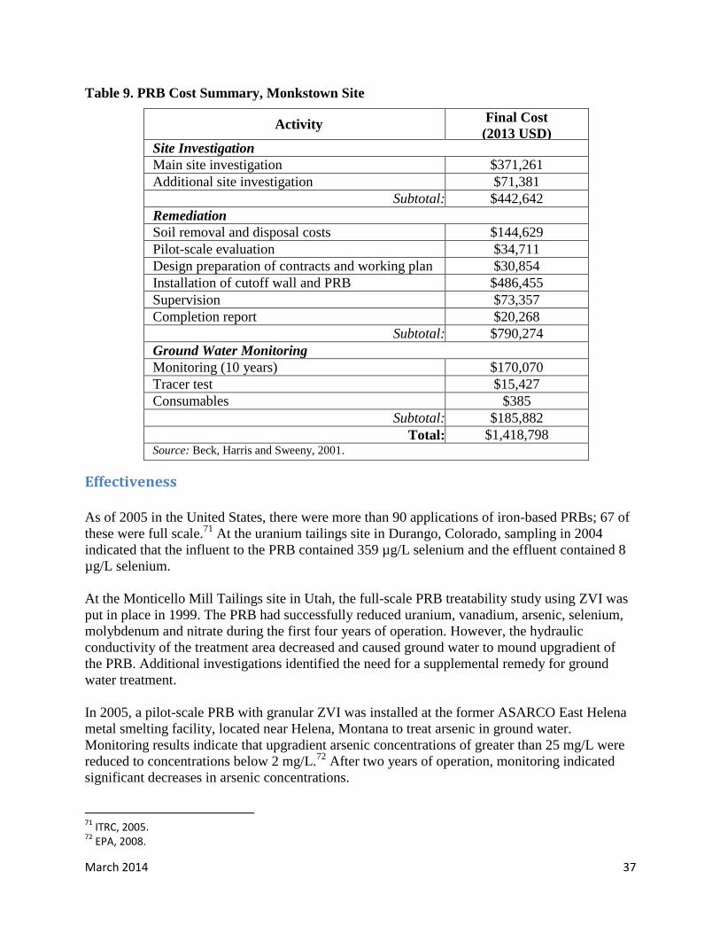
Table 9. PRB Cost Summary, Monkstown Site ............................................................................ 37
Table 10: Coal Mining Trial Operating Results at Canadian Coal Mines .................................... 41
Table 11: RCTS Treatment Results for Dissolved Metals at the Rio Tinto Mine, 2005 .............. 54
Table 12: ABMet® System Capabilities ...................................................................................... 69

March 2014 5
Acronyms and Abbreviations
ALD Anoxic Limestone Drain
ARD Acid Rock Drainage
BCWTP Bingham Canyon Water Treatment Plant
BCR Biochemical Reactor
C Celsius
CPFM Colloid Polishing Filter Method
ED Electrodialysis
EDR Electrodialysis Reversal
FBR Fluidized Bed Reactor
FF Filter Flow
FRTR Federal Remediation Technologies Roundtable
GARD Global Acid Rock Drainage
GPD Gallons per Day
GPM Gallons per Minute
ITRC Interstate Technology and Regulatory Council
L/min Liters per Minute
µg/L Micrograms per Liter
mg/L Milligrams per Liter
MGD Million Gallons per Day
MIW Mining-Influenced Water
ND Not Detected
OLC Open Limestone Channels
OU Operable Unit
O&M Operation and Maintenance
PRB Permeable Reactive Barrier
RCTS Rotating Cylinder Treatment System
SAPS Successive Alkalinity Producing Systems
SME Silica Micro Encapsulation

March 2014 6
TCLP Toxicity Characteristic Leaching Procedure
TDS Total Dissolved Solids
USD United States Dollars
EPA United States Environmental Protection Agency
ZVI Zero Valent Iron

March 2014 7
Notice and Disclaimer
This report compiles information on selected technologies for treatment of mining-influenced
water (MIW). The report includes those technologies that are used to treat MIW for which
information was readily available. It is not a comprehensive review of all current technologies.
The report contains information for interested stakeholders, including governments, the public
and the regulated community. The report does not provide guidance regarding the selection of a
specific technology, and the use of a specific technology may or may not result in compliance
with applicable federal, state or tribal environmental requirements, even if water quality
improves as a result of using a given treatment technology.
The mention of trade names, specific vendors or products does not represent an actual or
presumed endorsement, preference or acceptance by the United States Environmental Protection
Agency (EPA) or the federal government. Stated results, conclusions, usages or practices do not
necessarily represent the views or policies of EPA.
This report has undergone EPA and external review by experts in the field. However,
information in this report comes from many sources, some of which have not been peer
reviewed. EPA recommends that users refer to applicable regulations, policies and guidance
documents regarding selection of cleanup remedies and implementation of mine water treatment
and mine cleanup actions; selected references and additional resources are provided herein. The
Agency notes that this report may be revised periodically without public notice. EPA welcomes
public comments on this report at any time and will consider those comments in any future
revisions of the document.
Representatives from various EPA offices provided assistance with development of this report
and internal peer review. They include Bill Adams, Robin Anderson, Diana Bless, Barbara
Butler, Bette Conway, Anne Dailey, Elisabeth Freed, Gregory Gervais, Mike Gill, Doug Grosse,
Jim Hanley, Ed Hathaway, Gary Hudiburgh, Stephen Hoffman, Joy Jenkins, Tom Kady,
Michelle Kerr, Kira Lynch, Shahid Mahmud, Krista McKim, Carlos Pachon, Mark Purcell,
Elaine Suriano, Dave Tomten, Clifton Townsend, Stuart Walker and Andy Zownir. Additional
external reviews were provided by: Amanda Aspatore, National Mining Association; Tim
Buxton, USDA Forest Service; Mark Fitch, Missouri University of Science and Technology;
Gary Hickman and Jim Stefanoff, CH2M Hill; Ann Maest; David Reisman, CDM Smith; Brett
Waterman, Freeport McMoRan Copper & Gold; and Paul Ziemkiewicz, West Virginia
University.
EPA’s Office of Superfund Remediation and Technology Innovation prepared this report. For
further information about this report, please contact Michele Mahoney at EPA’s Office of
Superfund Remediation and Technology Innovation, at (703) 603-9057, or by email at

March 2014 8
Introduction
This report provides an overview of select mining-influenced water (MIW) treatment
technologies used or piloted as part of remediation efforts at mine sites. The report is intended to
provide information on treatment technologies for MIW to federal, state and local regulators, site
owners and operators, consultants, and other stakeholders. The technologies described in this
report are applicable to treatment of water from both coal and hard-rock mine operations. The
report provides short descriptions of treatment technologies and presents information on the
contaminants treated, pre-treatment requirements, long-term maintenance needs, performance
and costs. Sample sites illustrate considerations associated with selecting a technology. Website
links and sources for more information on each topic are also included.
MIW is defined as any water whose chemical composition has been affected by mining or
mineral processing and includes acid rock drainage (ARD), neutral and alkaline waters, mineral
processing waters and residual waters. MIW can contain metals, metalloids and other
constituents in concentrations above regulatory standards. MIW affects over 10,000 miles of
receiving waters in the United States, primarily by acidic drainage.1
EPA is evaluating more cost-effective and lower-maintenance treatment systems to decrease the
costs and improve the efficiency of mine site cleanups. Hence, this report focuses on passive
treatment methods, but also includes recently developed or not widely utilized active treatment
systems and passive-active hybrid systems. The report does not include all traditional active
technologies, such as lime precipitation or high-density sludge systems. Resources that
summarize these and other technologies include the Interstate Technology and Regulatory
Council (ITRC) Mining Waste Treatment Selection technology overview webpage
(http://www.itrcweb.org/miningwaste-guidance/technology_overviews.htm) and the Network for
Acid Prevention’s Global Acid Rock Drainage (GARD) Guide
(http://www.gardguide.com/index.php/Main_Page).
EPA’s policy for reducing the environmental footprint of activities used to clean up
contaminated sites is based on core element principles of reducing energy usage, air pollution,
and impacts on water resources, improving waste management, and protecting ecosystem
services. There are significant opportunities to reduce the environmental footprint associated
with characterizing MIW and using passive treatment systems. EPA’s green remediation best
management practices for treating MIW can be found at
http://cluin.org/greenremediation/docs/GR_factsheet_miningsites.pdf.
1 ITRC, 2008.

March 2014 9
In recent years, development and implementation of passive systems has increased. However,
additional pilot studies and case studies are needed to assess their effectiveness. With time, EPA
expects that the pool of technology options will expand and shift away from high-energy-use,
high-maintenance systems to low-energy-use, low-maintenance systems.
Active or passive methods can remove or reduce the concentration of contaminants in MIW. The
International Network for Acid Prevention’s GARD Guide considers active treatment as
technologies that require ongoing human operation, maintenance and monitoring, and have or
use external sources of energy, infrastructure and engineered systems. Passive treatment refers to
processes that do not require frequent human intervention, operation or maintenance, and that
typically employ natural construction materials (e.g., soils, clays, broken rock), natural treatment
media (e.g., plant residues such as straw, wood chips, manure, compost), and promote growth of
natural vegetation.2 Passive treatment systems use gravity flow for water movement, and passive
energy sources such as solar or wind power. In some arid climates, they might also include the
use of evaporation or infiltration. Both active and passive treatment methods potentially combine
physical, biological and chemical approaches to treat MIW. The main purpose of both classes of
technologies is to raise pH, lower dissolved metal concentrations, and lower sulfate. Active or
passive treatment of MIW generally requires long-term maintenance and funding.
Key factors when considering MIW treatment technologies include the amount of available land
surface and its topography; system longevity and maintenance needs; flow rate and strength; site
accessibility and remoteness; availability of utilities (especially power sources); performance
criteria; design, capital, and operation and maintenance costs; and climate impacts on system
effectiveness. Treatment systems typically include multiple steps of treatment with more than
one technology. Therefore, the associated costs of constructed systems are higher than the costs
included in this report for individual technologies. Although cost information is not available for
all technologies, the U.S. Office of Surface Mining has developed an online program for
evaluating cost of treatment methods, called AMDTreat. The program is available at
http://amd.osmre.gov/ and is designed to predict approximate costs for various sets of treatment
steps.
Methodology
EPA identified the MIW treatment technologies in this report by reviewing technical literature,
including EPA reports and EPA databases such as the Federal Remediation Technologies
Roundtable (FRTR: www.frtr.gov) and EPA’s Clean-Up Information (CLU-IN) website
(www.clu-in.org), and by contacting subject matter experts. Research included results of
2 GARD, 2009.

March 2014 10
demonstration projects conducted by EPA’s Superfund Innovative Technology Program and the
joint EPA and Department of Energy Mine Waste Technology Program. MIW treatment experts
reviewed this report. However, due to limited availability of relevant peer-reviewed publications,
some of the references cited may not have been peer reviewed. Examples of such sources include
site-specific reports and industry publications. In addition to the technologies discussed in this
report, engineering controls and source controls are important parts of managing MIW. Source
control strategies are outside the scope of this report.
MIW treatment technologies were identified and divided into active and passive approaches. For
each technology, the report summarizes the following information, where available: technology
description; technology operations; constituents treated; sites where the technology was applied
at full, pilot or bench scale; long-term maintenance requirements; system limitations; system
costs; and treatment effectiveness. The technologies included in the report are not a
comprehensive list of all treatment options. Based on the available information, EPA reviewed
the types of waste and contaminants treated and summarized the results from use of each
technology. Performance data are reported based on influent and effluent concentrations. For
many of the technologies described in this report, there were gaps in the available information.
EPA did not perform independent evaluations of technology performance in developing this
report.
The report provides detailed information on 16 technologies. These and additional technologies
are compiled in the Appendix A table. For each technology, the table provides information on
treated constituents, technology scale, example sites, operations, long-term maintenance
requirements, system limitations, costs, and effectiveness.
EPA will continue to evaluate MIW treatment technologies and solicit input on new
developments. EPA intends to build on this report by developing strategies for implementing and
expanding the use of passive treatment technologies.

March 2014 11
Technology: Anoxic Limestone Drains
Technology Description
Anoxic limestone drains (ALDs) involve the burial of limestone in oxygen-depleted trenches.
MIW is conveyed into these trenches. ALDs generate alkalinity and must be followed by a unit
such as an aeration cascade, pond or aerobic wetland that oxidizes and removes the precipitated
metals. Limestone is a low-cost and effective way to generate alkalinity. However, it must be
used in appropriate conditions to ensure its effectiveness.
Constituents Treated
ALDs treat acidity.
Operations
An ALD consists of a trench containing limestone encapsulated in a plastic liner that is covered
with clay or compacted soil (Figure 1). Surrounding the limestone with an impervious plastic
liner also helps maintain anoxic conditions in the drain. The soil used to cover the plastic must
consist of finely graded materials and be compacted to limit oxygen diffusion to the drain. The
anoxic conditions will prevent the oxidation of ferrous iron to its ferric state, which oxidizes
readily to ferric hydroxide in the presence of oxygen at pH values greater than 3.5. The cap also
prevents water infiltration and helps prevent carbon dioxide from escaping.
Figure 1: ALD Cross-Section
Prior to development and installation of an ALD, influent water must be characterized to ensure
effective system design. This includes looking at seasonal variations. In addition to flow rate,
important influent characteristics include dissolved oxygen content, acidity and alkalinity, ferric
and ferrous iron concentrations, and aluminum concentrations. If the pH is less than 5, iron

March 2014 12
concentrations should be speciated into ferric and ferrous. If ferric iron is present, the water may
need to be pretreated to reduce the ferric to ferrous ion. This reduction step is necessary because
ferric iron will precipitate and armor the limestone within the ALD, resulting in reduced
efficiency. At pH levels above 5, generally dissolved iron is in the ferrous form. Water quality
data will determine the applicability of an ALD, and flow data will provide sizing criteria for the
ALD.
Skousen (1991) found that high-grade limestone with CaCO3 content of greater than 90 percent
should be used.3 At this percentage, the limestone dissolves quickly, can obtain high alkalinity
levels in the water (near 300 milligrams per liter (mg/L) as CaCO3), and has fewer impurities
that could clog drains. Limestone used in ALDs is usually in the form of pebbles or rocks, with a
particle spectrum ranging from 1.5 to 4 inches. Small-size particles provide more surface area for
more rapid dissolution and alkalinity generation, while the larger-size particles will dissolve
more slowly and provide system longevity, and maintain distributed water movement through
the drain to limit short circuiting. A mixture of sizes will help ensure continuous flow through
the drain.
ALDs can be installed in remote areas due to their passive nature and the fact that utilities are not
required for implementation. ALDs may also be used to treat a wide range of MIW flow rates.
About 15 hours of contact time is necessary to achieve a maximum concentration of alkalinity.4
To achieve 15 hours of contact time within an ALD, 2,800 kilograms of limestone are required
for each liter per minute (L/min) of peak MIW flow.5 Therefore, ALD design typically involves
calculating the size and mass needed to create an effective system based on the flow rate.6
Figure 2: Anoxic Limestone Drain Outflow at the Midwestern Reclamation Site, Pike
County, Indiana
Image Source: http://igs.indiana.edu/Reclamation/Reclamation.cfm
3 Skousen, 1991.
4 Watzlaf, 2004.
5 Watzlaf, 2004.
6 ITRC, 2010.

March 2014 13
Once the water exits the drain, sufficient area must be provided for metal oxidation, hydrolysis
and precipitation to occur. Settling basins or ponds can be used for this purpose. State water
regulations governing alkalinity, pH, dissolved oxygen and hardness discharge limits should be
taken into account during ALD system design. Figure 2 above shows the vegetated cap of an
ALD in the background (see Figure 1 for an ALD cross-section diagram) and the outflow of
treated water.
Table 1: Examples of ALD Implementation
Valzinco Mine, Virginia
Mine Type: Underground lead/zinc/copper mine
http://www.itrcweb.org/miningwaste-
guidance/cs18_valizinco_mine.htm.
Copper Basin Mining, Tennessee
Mine Type: Underground and surface
copper mines
http://www.itrcweb.org/miningwaste-
guidance/cs2_copper_basin.htm.
Hartshorne/Whitlock-Jones, Hartshorne,
Oklahoma
Mine Type: Underground coal mine
http://www.itrcweb.org/miningwaste-
guidance/cs13_hartshorne.htm.
Ohio Abandoned Bituminous Coal,
Ohio
Mine Type: Underground and surface
coal mines
http://www.itrcweb.org/miningwaste-
guidance/cs1_se_ohio.htm.
Tecumseh - AML Site 262, Indiana
Mine Type: Surface coal mine
http://www.itrcweb.org/miningwaste-
guidance/cs37_tecumseh.htm.
Tennessee Valley Authority, Alabama
Mine Type: Underground coal mine
http://www.itrcweb.org/miningwaste-
guidance/cs33b_tva_alabama.htm.
Long-Term Maintenance
The limestone will need replenishment once depleted.7 Factors considered in the sizing of an
ALD include the levels of dissolved metals present in the mine drainage and the retention time
needed to raise the pH, as well as the amount of area available for construction.8 Dimensions are
typically about 1 meter deep, 1 to 7 meters wide, and 25 to 100 meters long, with the exact
dimensions of a system depending on the retention time desired, the influent flow rate and metals
concentrations, the purity of the limestone, discharge limits, and the length of time desired for
system longevity.9 Capping a system with topsoil and vegetation provides protection against
erosion.
7 ITRC, 2010.
8 ITRC, 2010.
9 Watzlaf, 2000a.

March 2014 14
System Limitations
Excessive iron and aluminum precipitation in an ALD will reduce the effective lifetime of the
bed by armoring the stone, resulting in reduced permeability and calcite dissolution rates. Metal
removal must occur elsewhere in the treatment process to prevent clogging of the limestone bed
and premature failure. The buildup eventually clogs the open pore spaces, resulting in abnormal
flow paths that can reduce both the retention time of MIW in the ALD and the reactive surface
area of the limestone.
Longevity of treatment is also a concern for ALDs in terms of water flow through the limestone.
Faulkner and Skousen (1994) and Watzlaf et al. (1994) have observed clogging of pores with
precipitated iron and aluminum hydroxides. The addition of calcium from limestone dissolution
can cause the precipitation of gypsum in MIWs with sulfate concentrations greater than 1,500
mg/L.10
Most ALD systems exhibit reduced effectiveness over time and eventually require
maintenance or replacement.
Although ALDs are documented to successfully raise the pH of MIWs, the chemical
characteristics of the influent mine water can cause variations in alkalinity generation and metal
removal.
ALDs are suitable for treatment of MIW with low concentrations of ferric iron, dissolved oxygen
and aluminum. However, when any of these three parameters are elevated, there can be armoring
of limestone, which will slow its dissolution rate because the surface becomes coated. The
buildup of iron and aluminum hydroxides can clog pore spaces, decrease retention times, and
reduce the reactive surface area of the limestone.
Costs
Constructing and operating ALDs to treat MIW can be cost effective. Specific constituents in the
water determine ALD installation costs. A typical ALD built at most locations in Canada costs
an estimated $6,000 to $37,000 (2013 USD), depending on chosen dimensions and design
flow.11
The ITRC reported capital costs at an abandoned mine in Alabama of about $0.27 per
1,000 gallons of water. Operation and maintenance costs were about $0.11 per 1,000 gallons of
treated water.12
Effectiveness
The success of an ALD depends on site-specific conditions, primarily on low dissolved oxygen,
and minimal ferric iron and aluminum concentrations in the drainage. Where these conditions
exist and the drains are properly constructed and maintained, a service life of 25 to 30 years is
anticipated. Watzlaf et al (2000b) assessed the long-term performance of 10 ALDs used for
10
Nairn, 1991. 11
MEND, 1996. 12
ITRC, 2010.

March 2014 15
treating coal mine drainage by analyzing a decade of influent and effluent water data. The
authors found that alkalinity in the effluent ranged from 80 to 320 mg/L as CaCO3, with levels
near maximum reached after about a 15-hour detention time in the ALD. Consistent alkalinity
values were achieved for over 10 years in ALDs where influent contained less than 1 mg/L of
ferric iron and aluminum.
Factors affecting the level of alkalinity include contact time, the influent partial pressure of
carbon dioxide, influent pH, the particle size of the crushed limestone, the CaCO3 content of the
limestone and the initial calcium concentration in the drainage.13
Contact time and the partial
pressure of carbon dioxide significantly affect the final concentration of alkalinity.14
Under the right circumstances and if constructed properly, limestone drains can add up to 300
mg/L alkalinity as CaCO3 to water.15
The amount of generated alkalinity is limited by the
dissolution rate of limestone in water. As pH decreases, limestone is more soluble and higher
amounts of alkalinity can be generated. In the absence of dissolved ferric iron and aluminum,
ALDs have continued to perform well with no significant seasonal variations or long-term
reduction in effectiveness.
Table 2 displays the treatment efficiencies observed at 10 ALD sites. All of the sites are located
in Pennsylvania, except the Elklick site, which is located in Maryland.
Table 2. Examples of ALD Efficiencies
ALD
Acidity1, mg/L
as CaCO3
Alkalinity,
mg/L as CaCO3
Calcium
(mg/L) pH Sulfate (mg/L)
In Out In Out In Out In Out In Out
Howe Bridge 1 472 352 32.6 155 115 223 5.74 6.30 1,319 1,314
Howe Bridge 2 411 274 35.3 163 157 209 5.40 6.48 1,210 1,211
Elklick 52 -63 33.8 159 258 232 6.06 6.73 334 327
Jennings 280 -33.5 0 139 ND 201 3.23 6.16 633 620
Morrison2 387 51.4 28.7 278 82.9 208 5.19 6.35 1,256 1,016
Filson – R2 100 -139 47.9 299 69.2 180 5.73 6.49 408 438
Filson – L2 104 -175 47.9 317 77.1 129 5.73 6.60 408 395
Schnepp3 307 -42.5 0 168 69.2 189 3.28 6.17 980 745
REM-R3 1,148 835 0 54 258 206 4.28 5.45 2,825 2,394
REM-L3 ND 259 ND 113 ND 198 ND 6.00 ND 1,256
Source: http://www.imwa.info/bibliographie/19_2_098-110.pdf.
Negative acidity values indicate that there is measurable alkalinity.
“In” concentrations based on water quality of a nearby seep.
“In” concentrations based on historical water quality data from untreated mine drainage prior to ALD construction.
Influent values are not available for REM-L.
ND = Not Determined
13
Watzlaf, 2000b. 14
Hedin, 1994. 15
Watzlaf, 2004.

March 2014 16
Technology: Successive Alkalinity Producing Systems (SAPS)
Technology Description
Successive alkalinity producing systems (SAPS) combine an ALD and a permeable organic
substrate into one system that creates anaerobic conditions prior to water contacting the
limestone.16
A SAPS contains a combination of limestone and compost overlain by several feet
of water (Figure 3). Mine drainage enters at the top of the pond, flows down through the compost
where the drainage gains dissolved organic matter and becomes more reducing, and then flows
into the limestone below, where it gains alkalinity.17
Dissolution of the limestone raises the pH
of the water, resulting in the precipitation of aluminum, copper and iron. The precipitated metals
collect at the base of the SAPS system and in the downstream settling pond.
Figure 3: Cross-section Diagram of a Typical SAPS
Constituents Treated
SAPS treat acidity and can reduce concentrations of aluminum, copper and iron.
Operations
Skousen (2000) describes a SAPS system consisting of acid water ponded from 1 to 3 meters
over an organic compost, which is underlain by 0.5 to 1 meter of limestone. The organic matter
stimulates the growth of sulfate- and iron-reducing bacteria and enhances or creates reducing
16 Skousen, 2000.
17 EPA, 2004.

March 2014 17
conditions, which prevent subsequent armoring of the limestone layer. Drainage pipes below the
limestone convey the water into an aerobic pond. The iron and sulfate can be reduced as the
water passes through the organic compost.
Data from Demchak et al. suggest that a minimum compost depth of 50 to 60 centimeters is
necessary for generating reducing conditions and that the selected compost should decompose at
a slow rate.18
Optimizing piping system design can improve metal removal. Preferential flow may occur when
using only one or two pipes; more pipes allow for more even flow.19
Precipitated aluminum and
iron hydroxides can clog the pore space in the limestone. To assess this effect, the laboratories of
the Division of Materials and Minerals at Cardiff University constructed a full-scale SAPS (in
cross-section).20
Study results suggested that the bed permeability will decrease over time, and
the SAPS will become clogged. The decreases in permeability are a function of the water flow
rates, substrate porosity, potential clogging and influent metal concentrations. Therefore, some
sites may require more complex designs that incorporate more treatment cells and settling ponds
constructed in series.21
Long-Term Maintenance
Regular maintenance is required to prevent system clogging and replenish the compost material.
Demchak et al. (2001) suggests adding new compost material after two to three years.
Monitoring for overflows and the pressure on the influent side of the system can indicate system
clogging and serve as an indicator that the limestone media may need to be replaced. Proper flow
control by diligent operation and maintenance efforts is essential to sustained system success.
System Limitations
Longevity is a concern for SAPS, especially in terms of water flow through the limestone. The
systems can be prone to clogging without regular maintenance. In addition, the dissolved oxygen
concentration of the influent is often a design limitation for SAPS.22
More complex systems
require additional design, construction and management, cost more, and also require a larger
footprint.
Costs
The average estimated cost for a SAPS based on a 15-year system life ranges from $72,439
(2013 USD) per year for a 5-gallons per minute (gpm) system to $150,983 (2013 USD) per year
18
Demchak et al., 2001. 19
Demchak et al., 2001. 20
Rees et al., 2001. 21
Demchak et al., 2001. 22
Kepler, 1994.

March 2014 18
for a 100-gpm system.23
For the 5-gpm system, estimated treatment costs are $0.03 per gallon of
acid mine drainage. For the 100-gpm system, estimated treatment costs are $0.003 per gallon.
Effectiveness
Long-term metals removal is possible, provided the water chemistry is first fully characterized
and the treatment design is based on the geochemistry results.
Table 3: SAPS Removal Efficiencies at Summitville Mine
Metal Removal Efficiencies
Aluminum 97%
Copper 90%
Iron 64%
Manganese 11%
Zinc 57% Source: EPA, 2004.
Kepler and McCleary (1994) verified the success of three SAPS in Pennsylvania. The same
researchers (Kepler and McCleary, 1997) reported the use of SAPs in Ohio, Pennsylvania and
West Virginia.24
In all cases, aluminum precipitated in the systems and was flushed using a
specialized system (see the Aluminator© technology summary for more information). Table 4
shows the treatment efficiencies observed at five SAPS sites.
Table 4: Removal Efficiencies at Five SAPS Sites
SAPS
Acidity,
mg/L as
CaCo3
Total Iron
(mg/L) pH
Total
Aluminum
(mg/L)
In Out In Out In Out In Out
Howe Bridge 320 93 NA NA NA NA NA NA
Schnepp
Road
84 5 NA NA NA NA NA NA
REM 173 88 NA NA NA NA NA NA
Buckeye 1,989 1,000 1,005 866 4.0 5.9 41 <1
Greendale 925 150 40 35 2.8 6.5 140 <1 Source: Kepler and McCleary, 1994 and 1997.
NA – Not available
23
EPA, 2004. 24
Kepler, 1994; Skousen, 2000.

March 2014 19
Technology: Aluminator©
Technology Description
The Aluminator© is a modified version of Damariscotta’s SAPS design. It is an adaptation of a
limestone drain in which aluminum hydroxide will accumulate for metals recovery. Instead of
using the impervious cap present in limestone drains, the Aluminator© system uses an organic
layer and water. The system is designed to operate under high iron and oxygen concentrations,
increase pH values and generate alkalinity, retain aluminum in the treatment system, and carry
out these functions with a minimum of operation and maintenance requirements.25 The
Aluminator© passive treatment system can treat a wide range of MIW flow rates. This
technology does not appear to have been widely applied.
Constituents Treated
The Aluminator© treats aluminum in MIW. It can also treat acidity and remove iron.
System Operations
The Aluminator© is set up similar to a SAPS, in which the base layer increases the pH of the
flow, generates alkalinity and retains aluminum. The additional design feature of the
Aluminator© allows for regular flushing of the system to remove precipitated aluminum buildup,
retaining the system’s effectiveness.26
Treated water is collected in a perforated piping system in
the limestone layer and is discharged (Figure 4). These pipes are specifically designed to the total
flow and aluminum concentrations. Valves in the piping system can be opened to flush the
system using the natural head of pooled water.
25
Kepler, 1994. 26
Kepler, 1994.

March 2014 20
Figure 4. Cross-Section of Typical Aluminator© System
Research conducted by D.A. Kepler and E.C. McCleary (1994) included descriptions of
Aluminator© usage at the Buckeye Reclamation Landfill in Belmont County, Ohio, and the
Little Mill Creek site in Jefferson County, Pennsylvania. The influent and effluent values for the
Buckeye and Little Mill Creek sites are included in Table 5. The effluent concentrations reflect
the Aluminator© portion of the treatment system. They were achieved immediately after
implementation and remained steady.

March 2014 21
Table 5: Buckeye Reclamation Landfill and Little Mill Creek System Results
pH Alkalinity
mg/L
CaCO3
equivalent
Acidity
mg/L
CaCO3
equivalent
Total
Iron
(mg/L)
Total
Aluminum
(mg/L)
Total
Manganese
(mg/L)
Buckeye
Reclamation
Landfill
Influent 3.98 0 1,989 1,005 41 4.2
Effluent 5.88 241 1,206 866 0.2 4.0
Little Mill
Creek
Influent 2.9 0 325 75 20 20
Effluent 6.1 54 167 68 <0.1 19
Long-Term Maintenance
Although Aluminator© systems require less operation and maintenance than active treatment
systems, some maintenance is still required. System efficiencies decline as interstitial spaces in
the substrates fill up, requiring occasional disposal of built-up wastes. Treatment effectiveness
can be maintained by periodically removing aluminum from the limestone with minimal
interruption of treatment. Greater than 80 percent of accumulated aluminum can be removed
from the system with a single flushing of the limestone.27
A downflow system operating under a
positive head is inherently better suited to both accumulating and flushing precipitates than a
lateral flow treatment strategy.
System Limitations
At sites with significant levels of aluminum and a low pH, system effectiveness declines more
rapidly. Efficiency can also decrease with sustained or uncontrolled high flow events. The
technology is limited to the withdrawal of aluminum and iron from MIW.
Costs
The Metro Coal Run watershed in Somerset County, Pennsylvania, consisted of two separate
Aluminator© systems, referred to as M1 and M2, each addressing an individual flow from circa
1930 deep mine seals.28
The M1 Aluminator© was built in spring 2001 and has a bottom
footprint of 70 feet by 140 feet. M1 holds roughly 2,900 tons of AASHTO #1 limestone and 240
cubic yards of organic compost, and has a design flow of 85 gpm. The M2 Aluminator© was
built in fall 2001 and has a bottom footprint of 40 feet by 200 feet. M2 incorporates 2,200 tons of
27
Kepler, 1994. 28
Kepler, 1993.

March 2014 22
AASHTO #1 limestone and 245 cubic yards of organic compost. A typical M2 flow may be 30
gpm; short duration peaks of 200 gpm can be expected. The Metro Aluminator© systems were
constructed with roughly 90 percent CaCO3 limestone, thereby requiring the dissolution of less
than 300 tons of stone per year for complete neutralization. The total capital cost of the M1
system was about $217,636 (2013 USD). The total capital cost of the M2 system was about
$131,901 (2013 USD).
Effectiveness
Results from the Buckeye Reclamation Landfill and Little Mill Creek sites indicate that these
systems can remove aluminum from MIW effectively. Typical results do not fluctuate with
seasons or temperatures, although efficiency can decrease with sustained or uncontrolled high-
flow events. Over the life of a system, decreased treatment efficiency is inevitable. However,
well-designed systems can be renovated as necessary to maintain optimum treatment efficiency.

March 2014 23
Technology: Constructed Wetlands
Technology Description
Constructed wetlands are built on the land surface using soil or crushed rock/media and wetland
plants. Constructed wetlands can be designed as aerobic wetlands, anaerobic horizontal-flow
wetlands and vertical-flow ponds (vertical-flow wetlands). Constructed treatment wetlands are
designed to treat contaminants over a long period and can be used as the sole technology, where
appropriate, or as part of a larger treatment approach. Contaminants are removed through plant
uptake, volatilization and biological reduction. The soil- and water-based microbes remove
dissolved and suspended metals from acid mine drainage. The primary advantages of wetland
treatment are low capital and operation and maintenance costs.
Constituents Treated
Wetlands can capture or treat sulfate and various metals, including iron, manganese, arsenic,
aluminum, copper, zinc, cadmium, selenium, nickel and lead. Wetlands can treat acidic, neutral
or alkaline mine drainage.
Operations
Constructed wetlands are primarily either subsurface flow wetlands or free water surface
wetlands (Figure 5).29
In a subsurface flow system, water flows through a granular media, such
as gravel or sand, and the media surface is planted with aquatic plants. A free water system is
similar to a natural wetland or marsh, with water flowing over the surface of a planted treatment
cell.
Figure 5. Vertical Flow and Horizontal Flow Constructed Wetlands
The design of a constructed wetland for the treatment of acid mine drainage varies with the site’s
characteristics. The most important design considerations are biochemical processes, loading rate
29 Golder, 2009.

March 2014 24
and retention time, slope, substrate, vegetation, sediment control, geometric configuration,
seasonality, and regulatory requirements.30
If the water is alkaline, aeration to enhance metal oxidation processes can be achieved with an
aerobic wetland. Neutralization of acidic water may be required, through the use of an ALD or
other pre-treatment. If the water is too acidic or if it contains too much ferric iron, aluminum or
dissolved oxygen, a compost wetland could increase alkalinity.
Figure 6. Cross-Section of a Constructed Wetland Design
Long-Term Maintenance
Constructed wetland systems are generally easy to maintain. Monitoring for saturation, spillover
and sedimentation is needed. Periodic dredging of sediments may be necessary. Wetlands work
well in remote locations or situations where constant monitoring or maintenance may be
impractical.
System Limitations
Constructed wetlands have several constraints: 1) they require a large amount of land per unit
volume of water; 2) a constant and sufficient supply of water is necessary to support the wetland;
3) influent MIW may require pre-treatment; and 4) periodic release of captured contaminants
may occur during high-flow periods or periods when vegetation decomposes, if pH changes and
resolubilization occurs or when desorption occurs.31
30 Rani et al., 2011.
31 CH2M Hill, 2010.

March 2014 25
Seasonality of the locale is an important factor in wetland design, particularly in areas where
climate fluctuations are significant. In cold climates, wetland removal efficiencies may decline
during winter.32
Wetland implementation requires an initial construction cost and upfront monitoring to make
sure the system is functioning and stable. Once in place, wetlands are slow to produce significant
results in comparison to active treatment technologies.
Costs
The construction cost of an anaerobic wetland in the Copper Basin Mining District in Ducktown,
Tennessee, in 1998 was about $1.4 million (2013 USD).33
This included the initial removal of
waste material and construction of the anaerobic cell. In 2003, the cost of adding the two
additional aerobic cells to the wetland was about $380,863 (2013 USD). This included the cost
of installing the two cells, adding a rock filter and restoring a segment of habitat.
The U.S. Naval Facilities Engineering Service Center’s Remediation Technology Online Help
Program lists the costs of constructed wetlands treatment at between $0.15 and $1.00 (2013
USD) per gallon of water treated.34
Effectiveness
Aerobic wetlands are generally more effective in removing iron than manganese and perform
best at low flow rates (Table 6).35
Seasonal variations in metal removal efficiency have been
noted, with lesser amounts removed in cold weather.
Table 6. Treatment Efficiencies Observed for Constructed Wetlands
Constituent Typical
Removal
Acidity 75-90%1,2
Sulfate 10-30%1,2
Iron >80-90%1,2
Aluminum >90%1,2
Copper >80-90%2
Zinc >75-90%2
Cadmium >75-90%2
Lead >80-90%2
Source: http://www.itrcweb.org/miningwaste-guidance/to_const_treat.htm.
1. For coal mine drainage
2. For metal mine drainage
32
Rani, 2011. 33
FRTR. 34
ITRC, 2010. 35
AML, 2004.

March 2014 26
After construction of the Copper Basin Mining District initial anaerobic wetland in Tennessee, a
performance study found that the wetland successfully reduced the acidity and concentration of
most of the metals, with the exception of manganese (Table 7).36
To help reduce the
concentrations of manganese, two additional aerobic cells were added to the wetland system in
2003. In addition, a rock filter was added to provide oxygenation, volatilization of hydrogen
sulfide and settling of metal precipitates.
Table 7. Maximum Post-Treatment Concentrations at Copper Basin Mining District
Constructed Wetland, 2004 to 2006
Influent (mg/L) Effluent (mg/L)
pH 4.28 7.16
Aluminum 1.423 0.055
Iron 0.211 0.133
Manganese 1.148 0.294
Copper 0.197 0.017
Zinc 0.640 0.197
Sulfate 110 104
Hardness 97 142
Flow (gpm) 294 241
Acidity 37 <1
Alkalinity <1 45 Source: http://www.epa.gov/aml/tech/cuwetlands.pdf.
All values are total concentrations, except for manganese, which is
dissolved.
36
EPA, 2006.

March 2014 27
Technology: Biochemical Reactors
Technology Description
Biochemical reactors (BCRs), or bioreactors, use microorganisms to remove contaminants from
MIW. BCRs can be constructed in various designs, including in open or buried ponds, in tanks,
or in trenches between mine waste and a surface water body.37
BCRs can address a wide range of
flows, acidity and metals loading. They can also operate passively or actively. Passive
bioreactors have successfully treated acid mine drainage-contaminated waters in pilot and full-
scale projects. Most BCRs at mine sites include sulfate-reducing bacteria and operate
anaerobically. As the sulfate is reduced in these systems, metals sulfides are precipitated and
removed.
Figure 7. Example of Passive BCR System
Image Source: http://www.itrcweb.org/miningwaste-guidance/to_bioreactors.htm.
Constituents Treated
BCRs effectively increase pH and remove sulfate and metals such as zinc, lead, copper,
cadmium, cobalt and nickel from MIW. Metals and metalloids (e.g., arsenic, chromium,
selenium, thallium and uranium) may also be removed.
37 ITRC, 2010.

March 2014 28
Operations
BCRs can be active or passive systems. Active systems include an external liquid source of
organic substrate and separate tanks or zones for the biological, chemical and physical (solids
separation) processes.38
Passive BCRs use a simple flow through design, with a solid reactive
mixture acting as a source of carbon for the bacteria and as a substrate for microbial attachment
and metal sulfide precipitation. In passive bioreactors, water flows through a solid reactive
mixture contained in a pond or a tank that consists of an organic carbon source, a bacterial source
or inoculum, a solid porous medium, a nitrogen source and a neutralizing agent.
Passive BCRs can receive the flow from the top, allowing for downflow through the system,
from the bottom, with an upflow through the system, or horizontally.39
The flow design dictates
the system transport and removal of metals.
The efficiency of passive bioreactors depends on the activity of bacteria, which is mainly
controlled by the composition of the reactive mixture. The organic substrate is generally a
mixture of locally available organic materials, and often contains limestone to provide additional
neutralizing capacity and gravel to increase substrate permeability. Selection of the organic
carbon source is usually based on availability and costs of the added electron donor per unit of
reduced sulfate. Sources of organic carbon include liquid ethanol, manure and wood chips, as
well as other materials such as fish bones, chitin, biosolids waste fluid and biosolids.40
BCR
applications indicate higher success in systems with a mixture of several contaminants as
opposed to a single organic carbon source.41
Flow equalization or pH adjustment may be required as a pre-treatment step to generate
consistent flow rates and pH to improve the effectiveness of BCRs. Minimum contact times
generally range from eight to 48 hours.42
Following treatment, post-treatment polishing steps
oxygenate the effluent and reduce toxicity.43
Long-Term Maintenance
In general, BCRs do not require extensive maintenance. However, performance can decline due
to substrate clogging. Clogging of the substrate can be reduced by adding inert gravel to the
mixture to provide structure to offset compaction. A replaceable cartridge system is an example
of such a substrate. Recycling systems in compost-based BCRs and flushing circuits in rock-
based BCRs have been used to remove any buildup in the BCR.44
38
ITRC, 2010. 39
Zagury, 2007. 40
ITRC, 2008. 41
Zagury, 2007. 42
ITRC, 2010. 43
Butler et al., 2011. 44
ITRC, 2010.

March 2014 29
System Limitations
The design of a BCR is based on the specific parameters and characteristics of the influent,
primarily the pH, flow, temperature, and the type and concentration of metals, as well as the
space available for the treatment system.45
In general, BCRs are built at least 3 to 4 feet deep.
Greater depths may be necessary in cold climates. In addition, extended periods of cold can
result in reduced performance, and high flows can stress the treatment system, although
insulation of the system can minimize the impact of below-freezing temperatures.46
Impacts on
the local area must also be considered. In particular, proximity to populated areas can be
problematic due to the strong odors and initial discoloration of the effluent.
Costs
The bioreactor system at the West Fork Mine site in Missouri was built for about $1 million
(2013 USD) in 1996. It has a 1,200-gpm capacity.47
In 2008, construction bids for a similar
system at Soudan Underground Mine State Park in Minnesota included a bid at $650,978 (2013
USD).48
A horizontal system was installed at the Prospector Square Development site in Park
City, Utah, in 2008 for approximately $400,000.49
A full-scale, compost-free bioreactor system was built at the Leviathan Mine in Alpine County,
California, in 2003. Capital costs for construction of the gravity-flow operation were
$1,062,100.50
Changing to the recirculation mode added nearly $38,000, for a total cost of about
$1.1 million (2013 USD). Operating at an average flow rate of 10 gpm, the system’s operation
and maintenance costs are $19.51 (2013 USD) per 1,000 gallons of treated acid mine drainage.
Effectiveness
The Luttrell BCR, located near Helena, Montana, is part of the Tenmile Creek Superfund site. It
has treated leachate from an on-site repository since 2003. Data indicate removal efficiency of 95
percent for most metals.51
Additional studies indicate that systems well suited to site-specific
characteristics are able to reduce acidity and remove more than 95 percent of metals.52
Various
types of media for gravel pit seepage can result in 98 percent removal of selenium and achieve
less than 5 micrograms per liter of selenium.53
In 2007, EPA conducted a pilot study at the Standard Mine in Colorado that demonstrated
passive, biological treatment of MIW is feasible at cold, remote, high-altitude sites.54
Results
45
ITRC, 2010. 46
Reisman, 2008. 47
Doshi, 2006. 48
Eger, 2009. 49
Fitch, 2009. 50
ITRC, 2006. 51
ITRC, 2010. 52
Reisman, 2008 and 2009. 53
CH2M Hill, 2010. 54
Reisman, 2009.

March 2014 30
from the first 13 months of BCR operation demonstrated high levels of metal removal, with
removal rates for cadmium, copper, lead and zinc of about 98 or 99 percent. However, despite
the high removal rates, BCR effluent continued to exceed discharge standards for cadmium, lead
and zinc.55
In addition, toxicity assessment of treated effluent from on-site passive bioreactors
has yet to take place on a regular basis. Studies at Luttrell indicate that in-field aeration improved
the removal of acute and short-term sub-chronic toxicity, most likely through removal of
hydrogen sulfide produced within the BCRs.56
55
Reisman, 2009. 56
Butler et al., 2011.

March 2014 31
Technology: Phytotechnologies
Technology Description
Phytoremediation technologies use plants to treat or capture contaminants in various media. Phytoremediation mechanisms include extraction of contaminants from soil or ground water;
hydraulic control of contaminated ground water; and control of runoff, erosion and infiltration by
vegetative covers. The mechanisms for removal of contamination by phytotechnologies include
concentration of contaminants in plant tissue; degradation of contaminants by various biotic or
abiotic processes; volatilization or transpiration of volatile contaminants from plants to the air;
and immobilization of contaminants in the root zone.57
Identifying the appropriate plant species
and soil amendments is essential to treatment success. Long-term maintenance is minimal once
the vegetation is established.58
Constituents Treated
Phytotechnologies can remove metals, including chromium, and radionuclides, including
uranium, cesium and strontium. Phytotechnologies are also used to control runoff, erosion and
infiltration.
Operations
If time and funding permit, soil or water from a site should be used in lab or greenhouse studies
to confirm the effectiveness of the site-specific treatment. Sites with widespread, low-to-medium
level contamination in the root zone are the best candidates for phytotechnologies.
Phytoremediation is a sustainable and green technology that does not require supplemental
energy.59
It generates minimal air emissions, water discharge and secondary wastes, and also
improves air quality and sequesters greenhouse gases. Phytotechnologies provide restoration and
land reclamation benefits during and after cleanup as well as habitat for plants and wildlife.
There are six basic phytoremediation mechanisms that can clean up mine sites:
phytosequestration, rhizodegradation, phytohydraulics, phytoextraction, phytodegradation and
phytovolatilization (Table 8).
57
EPA, 2000. 58
ITRC, 2010. 59
ITRC, 2010.

March 2014 32
Table 8: Common Phytoremediation Mechanisms Used in Mining Remediation60
Mechanism
Description Cleanup Goal
Phytosequestration
The ability of plants to sequester
certain contaminants in the rhizosphere
through exudation of phytochemicals
and on the root through transport
proteins and cellular processes.
Containment
Rhizodegradation
Exuded phytochemicals can enhance
microbial biodegradation of
contaminants in the rhizosphere.
Remediation by destruction
Phytohydraulics
The ability of plants to capture and
evaporate water and take up and
transpire water.
Containment by controlling
hydrology
Phytoextraction
The ability of plants to take up
contaminants in the transpiration
stream.
Remediation by removal of plants
Phytodegradation
The ability of plants to take up and
break down contaminants in the
transpiration stream through internal
enzymatic activity and photosynthetic
oxidation/reduction.
Remediation by destruction
Phytovolatilization
The ability of plants to take up,
translocate and subsequently transpire
volatile contaminants in the
transpiration stream.
Remediation by removal through
plants
Long-Term Maintenance
The majority of maintenance is required during the initial years to ensure the vegetation
establishes itself. Replanting or additional soil modifications may be needed, as well as
irrigation, weed and pest control.61
System Limitations
Root contact is a primary limitation on phytoremediation applicability. Remediation with plants
requires that the contaminants be in contact with the root zone of the plants. The plants must be
able to extend roots to the contaminants, or the contaminated media must be moved to within
range of the plants. This movement can be accomplished with standard agricultural equipment
60
ITRC, 2010. 61
ITRC, 2010.

March 2014 33
and practices. However, because these activities can generate fugitive dust and volatile organic
compound emissions, potential risks may need to be evaluated.62
Pests, infestations and the availability of water as an irrigation source are all possible limitations
associated with this technology. However, proper plant selection can overcome many of these
limitations. Phytotechnologies also typically require larger tracts of land than many remedial
measures.
Phytoremediation is also limited by seasonality and the growth rate of the plants. More time may
be required to phytoremediate a site as compared with other, more traditional cleanup
technologies. High concentrations of contaminants may also inhibit plant growth and thus limit
application on some sites or some parts of sites.
Costs
Total system costs for some phytoremediation applications can be 50 to 80 percent lower than
for active treatment technologies.63
Establishment of phytotechnology systems includes various
activities and expenses, such as earthwork, labor, planting stock, planting method, field
equipment, heavy machinery (typically farming or forestry equipment), soil amendments,
permits, water control infrastructure, utility infrastructure and fencing. According to the ITRC,
10 to 15 percent of a project’s initial capital costs should be added as a contingency for
replanting.64
Operation and maintenance costs can include labor, sampling, analytical work,
materials, field equipment, utilities, waste handling and disposal. Once the vegetation becomes
established, operation and maintenance costs tend to diminish.
Effectiveness
Factors affecting the effectiveness of phytoremediation include the contaminant type and
concentration, soil conditions, hydrogeologic conditions, the plant species and growth rate, and
climate conditions. Sites with low concentrations of contaminants over large cleanup areas and at
shallow depths are best suited for phytoremediation. Long-term monitoring may be needed to
demonstrate the effectiveness and to prevent the introduction of contaminants to the human food
chain.
62
EPA, 2000. 63
EPA, 2000. 64
ITRC, 2010.

March 2014 34
Technology: Permeable Reactive Barriers
Technology Description
A permeable reactive barrier (PRB) consists of a permeable treatment zone in which reactive
material has been placed and through which contaminated water flows (Figure 8). With most
PRBs, reactive material is in direct contact with the surrounding aquifer material. Reactive
materials include ZVI, limestone, compost, zeolites, activated carbon and apatite.
When properly designed and implemented, PRBs are capable of remediating many different
contaminants to regulatory concentration goals. Data indicate that these systems, once installed,
will have extremely low, if any, maintenance costs for at least five to 10 years.65
There should be
no operational costs other than routine compliance and performance monitoring.
Figure 8: PRB Diagram
Image Source: http://clu-in.org/download/rtdf/prb/reactbar.pdf.
Constituents Treated
This technology has successfully treated many different constituents, including radionuclides,
trace metals, and anion contaminants. Trace metals treated include hexavalent chromium, nickel,
lead, uranium, technetium, iron, manganese, selenium, copper, cobalt, cadmium and zinc. Anion
contaminants treated include sulfate, nitrate, phosphate and arsenic.
65 EPA, 1998.

March 2014 35
Operations PRBs are currently built in two basic configurations: the funnel-and-gate and the continuous
PRB. Newer techniques for emplacing reactive media include injection of slurries, hydro-
fracturing and driving mandrels. PRBs can be installed as permanent or semi-permanent units.
The most commonly used PRB configuration is a continuous trench in which the treatment
material is backfilled. The trench is perpendicular to and intersects a ground water plume.
The funnel-and-gate PRB design uses impermeable walls (e.g., sheet pilings, slurry walls) as a
“funnel” to direct the contaminant plume to a “gate” containing the reactive media. In contrast,
the continuous PRB design completely transects the plume flow path with reactive media. Due to
the funnels, the funnel-and-gate design has a greater impact on altering the ground water flow
than the continuous PRB. In both designs, it is necessary to install the PRB to the bedrock and to
keep the reactive zone permeability equal to or greater than the permeability of the aquifer to
avoid diversion of the flowing waters around the reactive zone.
Reactive material is placed in the subsurface where a plume of contaminated ground water
passes through, typically under natural pressure conditions, and treated water comes out the other
side. The PRB is a barrier to the contaminants, not to the water. The basic objective of any PRB
treatment material is to either directly degrade or immobilize target chemicals in ground water or
to change the geochemical conditions of the ground water system such that the destruction or
immobilization of the target chemicals is promoted.
ZVI is the most widely used reactive material in PRBs, due to its ability to treat common organic
and inorganic contaminants in ground water.66
Other iron- and non-iron-based materials are also
being used in pilot-scale and full-scale PRB applications or are being evaluated in laboratory or
bench-scale demonstration projects because of their ability to treat additional contaminants, such
as radionuclides, heavy metals and MIW.
A complete site characterization is of critical importance for the design and installation of a
reactive barrier. The characterization should include an evaluation of the surface features,
structures and buried services. This characterization will determine whether the site is amenable
to PRB installation and the types of PRB emplacement technologies feasible at the site.
Several important issues must be addressed when considering PRB technology for contaminant
remediation. The plume location and extent, ground water flow direction and velocity, and
contaminant concentrations must be known to achieve the required performance. In addition,
information on stratigraphic variations in permeability, fracturing and aqueous geochemistry is
needed for the PRB design. The plume must not pass over, under or around the PRB. The
reactive zone must reduce the contaminant to concentration goals without plugging with
precipitates.
66
ITRC, 2005.

March 2014 36
Long-Term Maintenance
Once in place, minimal maintenance is required for PRBs. However, performance can decline
over time due to clogging.67
Precipitates will eventually cause a reduction in permeability;
therefore, removal of precipitates could represent a significant operation and maintenance cost
for PRB technology. Based on many laboratory evaluations of porosity loss, and fewer
evaluations at field sites, some maintenance could be required in highly mineralized and/or
oxygenated ground water as frequently as every five years to manage potential problems caused
by precipitate formation. In less mineralized waters, maintenance frequency could be as low as
every 10 to 15 years.68
System Limitations
PRBs are generally not the only remedy for a site. Additionally, since most PRBs operate
passively, site remediation may take several years or even decades, requiring the use of long-
term institutional controls for site management. Therefore, a PRB should be considered in the
context of overall and long-term site remediation goals.
Biofouling and mineral precipitation may limit the permeability of the wall system if not
managed properly. Disposal issues could develop in the PRB treatment media after the
contaminants are concentrated within the barrier system. This factor is most important in PRB
systems that retain the contaminants (e.g., metals and radionuclides), as opposed to PRB systems
that degrade the contaminants (e.g., hydrocarbons and chlorinated organics) as they flow through
the system.
Costs
The passive functioning of a PRB means that relatively little energy or labor input (except for
site monitoring) is necessary; thus, the technology has a potential advantage over conventional
ground water treatment methodologies, such as pump-and-treat systems. Overall, while the costs
of PRB systems vary depending on site-specific circumstances, the length and especially the
depth tend to be the biggest factors that drive the cost of the installation. Once installed, PRBs
are generally less expensive to maintain than active systems.69
A PRB was installed at a uranium tailing site in Durango, Colorado, at a cost of about $29.68 per
1,000 gallons treated (2013 USD).70
For a PRB installed in Monkstown, Northern Ireland, total
treatment costs were $1.4 million (2013 USD).
67
CH2M Hill, 2010. 68
EPA, 1998. 69
ITRC, 2010. 70
US DOE, 2004.
March 2014 37
Table 9. PRB Cost Summary, Monkstown Site
Activity Final Cost
(2013 USD) Site Investigation
Main site investigation $371,261
Additional site investigation $71,381
Subtotal: $442,642
Remediation
Soil removal and disposal costs $144,629
Pilot-scale evaluation $34,711
Design preparation of contracts and working plan $30,854
Installation of cutoff wall and PRB $486,455
Supervision $73,357
Completion report $20,268
Subtotal: $790,274
Ground Water Monitoring
Monitoring (10 years) $170,070
Tracer test $15,427
Consumables $385
Subtotal: $185,882
Total: $1,418,798 Source: Beck, Harris and Sweeny, 2001.
Effectiveness
As of 2005 in the United States, there were more than 90 applications of iron-based PRBs; 67 of
these were full scale.71
At the uranium tailings site in Durango, Colorado, sampling in 2004
indicated that the influent to the PRB contained 359 µg/L selenium and the effluent contained 8
µg/L selenium.
At the Monticello Mill Tailings site in Utah, the full-scale PRB treatability study using ZVI was
put in place in 1999. The PRB had successfully reduced uranium, vanadium, arsenic, selenium,
molybdenum and nitrate during the first four years of operation. However, the hydraulic
conductivity of the treatment area decreased and caused ground water to mound upgradient of
the PRB. Additional investigations identified the need for a supplemental remedy for ground
water treatment.
In 2005, a pilot-scale PRB with granular ZVI was installed at the former ASARCO East Helena
metal smelting facility, located near Helena, Montana to treat arsenic in ground water.
Monitoring results indicate that upgradient arsenic concentrations of greater than 25 mg/L were
reduced to concentrations below 2 mg/L.72
After two years of operation, monitoring indicated
significant decreases in arsenic concentrations.
71
ITRC, 2005. 72
EPA, 2008.

March 2014 38
Technology: Fluidized Bed Reactor
Technology Description
In a fluidized, or pulsed, bed reactor, contaminated water passes through a granular solid media,
such as sand or granular activated carbon, at high enough flow rates to fluidize the media,
creating a mixed reactor configuration for attached biological growth or biofilm (Figure 9). Fluidized bed reactors (FBRs) can be designed as aerobic or anaerobic systems. Removal of
solids following the biological treatment system is required.
Figure 9: Example FBR System Design
Image Source: http://www.envirogen.com/files/files/FBR_Brochure-draft-Rev_9-4-pges-Sept_2011.pdf.
Constituents Treated
Constituents treated by FBRs include selenium, chromium, nitrate and perchlorate.
System Operations
FBRs are active treatment systems that foster the growth of microorganisms on a hydraulically
fluidized bed of fine media. A fluid is passed through granular solid material at velocities
sufficient to suspend the solid media. Fluidizing the media increases the active surface area,
allowing for increased microorganism growth and contaminant treatment.73
During start up, the FBR is seeded with heterotrophic bacteria. Electron donor materials and
nutrients are pumped into the anaerobic FBR to promote microbial growth. The process uses
73 Envirogen, 2011.

March 2014 39
naturally occurring microbes and biodegradable carbon sources to maintain biomass.
Contaminated water is then pumped from a feed tank into the FBR in an upward flowing
direction to suspend the media. As microorganisms grow on the media, the fluidized bed height
expands. Over time, a biofilm develops on the media surface.74
In anoxic systems, nitrate and
selenium reduction occur on this biofilm. Treated water from the FBR system is then discharged
to a downstream liquid/solids separation system.
Figure 10: Envirogen’s FBR Model EFB-14
Image Source: http://www.envirogen.com/files/files/FBR_Brochure-draft-Rev_9-4-pges-Sept_2011.pdf.
Anoxic FBR systems can treat inorganic contaminants such as nitrate and selenium.75
The
systems routinely achieve discharge limit conditions. Manufacturers can design these systems as
modular units for use in remote areas. Another benefit of these types of systems is their relatively
small footprint, which ultimately results in lower total installed costs. Depending on influent
characteristics, FBRs may not require extensive pre-treatment for suspended solids.
Following treatment, aeration may be required to increase dissolved oxygen and remove
biochemical oxygen demand. Adjustment to pH may also be required prior to and following
treatment. Other byproducts requiring post-FBR polishing may include dissolved iron,
manganese and sulfide.
Long-Term Maintenance
Due to the biological growth inherent in FBRs, daily cleaning of the influent strainer, tank walls,
recycle tank and piping are required. Pre-treatment and post-treatment pH adjustment may be
74 CH2M Hill, 2010.
75 CH2M Hill, 2010, Envirogen 2011.

March 2014 40
required, as well as period media replacement. Biosolids must be thickened and dewatered prior
to landfill disposal.
System Limitations
Common limitations associated with FBRs include the inability to handle high feed nitrate,
selenium and suspended solids concentrations.76
This is due to problems of rapid plugging,
nitrogen gas binding, channeling and high backwash requirements. Additionally, the presence of
excessive amount of nitrates will require a proportional amount of carbon or energy sources. An
external carbon source is needed to meet influent organic content or chemical oxygen needs.
This excess carbon source will also generate some additional biomass.
FBRs are temperature sensitive and do not perform as well below 10° C. Water below 10° C
would require thermal treatment to heat the waste stream. While FBRs require high-energy
inputs, some abandoned mine flows have sufficient pressure to provide enough head for
fluidization of the bed.77
FBRs do lose efficiency in cold weather environments and the
generated sludge may be hazardous, requiring proper disposal.
Costs
FBRs are energy intensive, requiring high operating power costs relative to other systems, and
the electron donor and nutrient provision can be expensive. Solids removal, which may require
membranes, can greatly add to operating and capital costs. Total installed cost for a 1 million
gallon per day (gpd) system is estimated at $11.8 million (2013 USD), but can cost significantly
more.78
The annual operation and maintenance cost for the same system is estimated at $3.2
million (2013 USD).
Effectiveness
Envirogen Technologies offers a patented fixed-film FBR biological treatment technology that
reportedly demonstrated the ability to achieve less than 5 micrograms per liter (µg/L) selenium
over a 10-month period in treating mining leachate at a coal mining site.79
This system was
designed to handle a flow of 2,800 gpm, with a design temperature of 10º C and a typical
hydraulic residence time of 26.8 minutes. Table 10 shows results of this trial. There was also a
four-month trial at a Canadian coal mine examining Envirogen FBR technology in the presence
of high nitrate levels and at colder influent water temperatures. Table 10 shows results of this
trial as well. This system was designed to handle a flow of 2,800 gpm, with a design temperature
of 4º C and a typical hydraulic residence time of 56.9 minutes.
76
CH2M Hill, 2010. 77
Riefler, 2007. 78
CH2M Hill, 2010. 79
Envirogen, 2011.

March 2014 41
Table 10: Coal Mining Trial Operating Results at Canadian Coal Mines
Constituent Feed Concentration Effluent Concentration
Site 1
Dissolved Selenium 22 to 27 µg/L 4.7 µg/L maximum
Nitrate – Nitrogen as N 6 to 8 mg/L
Dissolved Oxygen 11 to 13 mg/L
pH 7 to 9
Site 2
Dissolved Selenium 200 to 500 µg/L 10 µg/L maximum
Nitrate – Nitrogen as N 15 to 40 mg/L
Dissolved Oxygen 11 to 13 mg/L
pH 7 to 8 Source: Envirogen, 2011.
The EPA Mining Waste Technology Program tested a pulsed limestone bed technology at the
Argo Tunnel water treatment facility in Idaho Springs, Colorado.80
A 60-gpm system was able to
increase pH from 3.0 to 7.0, remove greater than 98 percent iron and aluminum, and produce an
effluent alkalinity of about 100 mg/L as calcium carbonate. Manganese and zinc in the effluent
required additional treatment. Overall, results indicated a decrease in reagent costs and a
decreased sludge volume due to the replacement of lime or sodium hydroxide by limestone as the
neutralization agent.
80
Sibrell, 2005.

March 2014 42
Technology: Reverse Osmosis
Technology Description
Reverse osmosis is the pressure-driven separation of contaminants through a semi-permeable
membrane that allows water to pass through while retaining contaminants. The dissolved ions are
retained in a concentrated brine solution that requires management or disposal (Figure 11).
Reverse osmosis is a proven method to demineralize acid mine drainage. However, it does
require significant construction and operating costs.
Figure 11: Diagram of Simplified Reverse Osmosis Technology
Constituents Treated
Reverse osmosis can be used to remove metals, total dissolved solids, and sulfate from MIW.
Operations
Reverse osmosis involves a semipermeable membrane through which almost pure water is
removed from a concentrated input solution by applying pressure, leaving a more highly
concentrated brine solution. The membrane is the primary component of a reverse osmosis
system. Durable membranes resistant to chemical and microbial agents that retain structural
stability over long operating periods are essential. Pre-treatment is necessary to prevent
membrane fouling, particularly if the water contains elevated levels of hardness (i.e., calcium or
magnesium) or total suspended solids. With pre-treatment and routine maintenance, membranes
typically last two to five years.81
81 CH2M Hill, 2010.

March 2014 43
The brine produced is typically 20 to 30 percent of the influent flow in a single system,
depending on influent water quality. The process produces a concentrated waste stream that must
be disposed of properly. Various disposal options are available. However, the concentrated waste
stream is typically disposed of through evaporation, deep well injection or ocean discharge.
Reverse osmosis has been used successfully to treat MIW at several sites. At the Barrick
Richmond Hill Mine near Lead, South Dakota, reverse osmosis polishes selenium from mine
water after pre-treatment for iron reduction and precipitation. The reverse osmosis unit is
operated at pressures of 250 pounds per square inch and greater.82
As of 2005, filtration pre-
treatment was required to remove total suspended solids. During winter months, water is heated
to prevent crystallization caused by depressed salt solubilities. Additionally, a softening plant is
under consideration for treating gypsum scaling resulting from elevated calcium concentrations.
At a historic former gold mine in California, reverse osmosis treated impounded water as an
emergency measure to prevent impounded water from affecting a drinking water reservoir below
the mine.83
Trailer-mounted reverse osmosis systems were leased along with pre-filtration and
manganese removal columns. The system flow was greater than 100 gpm and the system
operated for about four months. The system operated at about 40 percent selenium recovery due
to the high total dissolved solids in the influent water. The brine was then returned to the initial
impoundment. Selenium concentrations were reduced from about 60 µg/L to less than 5 µg/L.
The system operated until levels in the impoundment were reduced to acceptable levels.
Reverse osmosis is also in use at the Kennecott South site, which is located in the Salt Lake
Valley, east-southeast of Copperton, Utah.84
The Bingham Canyon Water Treatment Plant
(BCWTP), built as part of the site’s remedy, is located in operable unit (OU) 2. Reverse osmosis
is being used as the primary technology for addressing total dissolved solids- and sulfate-
impacted ground water.
The BCWTP has two reverse osmosis treatment racks that treat 3,200 gpm with total dissolved
solids concentrations of about 2,000 mg/L and a sulfate concentration of 1,200 mg/L.85
The
quality of the feed water and regular cleaning has extended the system’s lifespan to about six
years.
82
Microbial Technologies, 2005. 83
Golder, 2009. 84
ITRC, 2010. 85
ITRC, 2010.

March 2014 44
Figure 12: Two Reverse Osmosis Treatment Racks at the BCWTP
Image Source: http://www.itrcweb.org/miningwaste-guidance/cs48_kennecott_south.htm.
Long-Term Maintenance
Frequent membrane monitoring and maintenance are required to ensure the effective operation of
a reverse osmosis system. With pre-treatment and the performance of routine maintenance,
membranes typically last two to five years. If membranes become fouled due to lack of pre-
treatment or water chemistry, or when they reach the end of their effective lifespan, proper waste
disposal is required. Following the performance of a waste determination, proper waste disposal
is required consistent with a waste determination.
To minimize viscosity effects that inhibit performance, water temperature controls may be
needed at low and high temperatures. Adjustment to pH and the addition of antiscalant to prevent
membrane fouling may also be required.86
Brine concentrates generated during the reverse
osmosis process must either be treated or further concentrated for proper disposal. The treated
stream may also require pH and total dissolved solids buffering prior to discharge to receiving
waters to meet regulatory requirements.
System Limitations
The primary constraint is the need for high operating pressure and associated energy and costs to
push the water through the membrane to remove high levels of total dissolved solids. The
technology is not practical above 10,000 mg/L total dissolved solids.87
86 CH2M Hill, 2010.
87 CH2M Hill, 2010.

March 2014 45
Pre-treatment and chemical additions are required to reduce membrane scaling and fouling.
Scale-forming ions will irreversibly foul the membranes and create selenium removal issues by
allowing leakage. Disposal of brine solution is also required. In addition, low ionic-strength
effluent lowers hardness and alkalinity in receiving streams, which can increase susceptibility of
aquatic biota to metals toxicity.
Costs
Reverse osmosis typically requires high capital costs for the purchase, installation and operation
of the membrane system. For a 1-million-gpd system, the total installed cost is estimated at $42.9
million (2013 USD).88
Annual operation and maintenance costs for the same system are
estimated at $3.2 million (2013 USD). Management and disposal of the brine solution that is
generated can require higher operating costs. In arid climates, atmospheric evaporation may offer
a technique for removing water in the brine solution followed by appropriate solid waste
disposal. For locations where atmospheric evaporation is not feasible, thermal treatment may be
needed.
The total cost for the BCWTP was about $16.1 million (2013 USD).89
Total yearly operation and
maintenance costs (40 percent of these costs represent labor and 24-hour maintenance) for the
BCWTP are about $1.3 million (2013 USD). These capital and yearly operation and maintenance
costs include energy requirements, but do not reflect the costs associated with extraction wells,
feed pipelines, disposal infrastructure and off-site disposal.
According to Golder Associates, the capacity of a permanent reverse osmosis facility used to
treat waste rock leachate was 60 gpm and included an evaporator for brine management. The
capital cost of the system was estimated at $5.6 million (2013 USD).90
The operation and
maintenance cost was estimated at $19.28 (2013 USD) per 1,000 gallons of water treated.
Effectiveness
The BCWTP at the Kennecott South site has consistently seen permeate reduction efficiencies of
71 to 72 percent.91
Between June 2006 and May 2009, total dissolved solids removal efficiencies
at the BCWTP averaged 98.9 percent. Between 2007 and 2009, product water also consistently
complied with all applicable State of Utah primary and secondary drinking water standards.
Product water continues to remain in compliance with permit limitations established by the State
of Utah’s Division of Drinking Water.
88
CH2M Hill, 2010. 89
ITRC, 2010. 90
Golder, 2009. 91
ITRC, 2010.

March 2014 46
At the Barrick Richmond Hill Mine, reverse osmosis concentrates selenium from mine water
after treatment by iron reduction and precipitation. Selenium is reduced from 22 µg/L to 12 µg/L
to about 2 µg/L at flows of 200 gpm.92
Reverse osmosis systems have been demonstrated at full scale to remove selenium (selenate or
selenite) to less than 5 μg/L and to remove 90 to 98 percent of total dissolved solids.93
At a
historic former gold mine in California, reverse osmosis was used to treat impounded water for
reduction of selenium from about 60 μg/L to less than 5 μg/L, with a flow rate of greater than
100 gpm.
92
Golder, 2009. 93
Golder, 2009.

March 2014 47
Technology: Zero Valent Iron
Technology Description
Zero valent iron (ZVI) can be used in active MIW treatment systems to rapidly neutralize acid
and promote removal and immobilization of dissolved heavy metals. Adsorption onto the iron
metal surface, or onto iron corrosion products initially present on the unreacted metal surface,
facilitates the rapid removal of metals from MIW. ZVI can reduce selenium oxyanions to
elemental selenium. Ferrous cations can also reduce selenate to selenite and subsequently
remove selenite by adsorption to iron hydroxides. In an aqueous environment, ZVI can be
oxidized to dissolved ferric (Fe3+
) and ferrous (Fe2+
) ions. These ions react with hydroxyl ions
present in water to form ferric and ferrous hydroxides. Selenate is reduced to selenite while
ferrous iron is oxidized to ferric iron. Selenite then adsorbs to the ferric and ferrous hydroxide
surfaces and is removed from solution.
Constituents Treated
Constituents treated by ZVI include selenium, arsenic and radionuclides.
Operations
In the treatment of MIW, ZVI is added as a reducing agent and acts as both a catalyst and an
electron donor for the reaction.94
As the ZVI is oxidized, green rust forms, which is required to
abiotically reduce selenate to selenite and selenite to elemental selenium.
Anoxic conditions are needed for successful treatment. ZVI treatment systems have typically
applied the media in covered tanks or filter vessels that hold elemental iron (Figure 13).95
Multiple tanks in series can be used to increase treatment. Aeration and oxidation of the iron is
needed downstream of ZVI tanks prior to discharging to the outfall.
94
CH2M Hill, 2010. 95
CH2M Hill, 2010.

March 2014 48
Figure 13. ZVI Process Diagram Using Column Setup with Steel Wool
The iron can come in several forms, including filings, steel wool, iron-impregnated foam, and
granular micro- or nano-scale particles.96
The form determines the surface area available for the
reactions. The presence of sulfate-reducing bacteria in ZVI systems will offer additional
pathways for metal removal (i.e., precipitation of insoluble metal sulfides). Depending on input
pH, significant accumulations of precipitates containing iron, aluminum and manganese might be
expected.
A 2003 lab evaluation examined the applicability and limitations of granular ZVI for the
treatment of water affected by mine wastes.97
The results indicated metal removal from solution
and acid-neutralization occurred simultaneously and most rapidly during the initial 24 hours of
reaction. Results indicated that metal removal is most effective in solutions highly
undersaturated with respect to pure-metal hydroxides, suggesting that adsorption is the initial and
most rapid metal uptake mechanism. Reversibility studies indicate that ZVI will retain metals
after shifts in redox states are imposed. However, remobilization of metals may occur after the
acid-neutralization capacity of the material is exhausted. Rates of acid-neutralization and of
metal (copper, cadmium, nickel, zinc, mercury, aluminum and manganese) and metalloid
(arsenic) uptake were determined in batch systems using simulated mine drainage (initial pH 2.3
to 4.5; total dissolved solids 14,000 mg/L to 16,000 mg/L).
96 CH2M Hill, 2010.
97 Wilkins, 2003.

March 2014 49
At the Barrick Richmond Hill Mine near Lead, South Dakota, ZVI reduces selenate to selenite,
followed by ferric sulfate precipitation at pH 4.5.98
The process is able to remove selenium to
concentrations of 12 to 22 µg/L. At another mine site, ZVI and ferrous sulfate at pH 4.5 are used
to reduce selenate to selenite. Ferric chloride is then added to form ferric hydroxide, which co-
precipitates the selenite.
In 2008, at the Catenary Post site in West Virginia, steel wool (fibrous ZVI) was used to remove
selenium from MIW in a continuous flow reactor.99
Problems with the treatment process
included the formation of iron oxides, passivation of the iron, exhaustion of the iron, and cost.
Long-Term Maintenance
ZVI requires removal, appropriate disposal and replacement, generally within a few months to a
few years. Iron residuals with adsorbed selenium typically go through thickening and dewatering
processes prior to disposal in a landfill. However, prior to disposal, residuals may require
toxicity characteristic leaching procedure (TCLP) testing to determine if the sludge needs to be
disposed of as hazardous waste.
System Limitations
Although ZVI can effectively treat MIW, additional treatment methods are likely needed to meet
discharge requirements. Pre-treatment may be necessary to adjust pH. Influent temperatures may
need to be adjusted to improve removal efficiencies. The formation of green rust begins at a pH
greater than 4 and begins to diminish at a pH greater than 5; therefore, a pH range of 4 to 5 is
ideal for efficient treatment.100
The temperature will affect the reaction kinetics, or rate at which
selenium reduction occurs. Low temperature will reduce reaction kinetics; therefore, the systems
should be designed appropriately. Treatment generally requires a residence time of four hours or
greater to adequately remove metals. Passivation of the iron may also occur, depending on the
presence of other metal redox reactions, chemical scale and/or suspended solids that will
accumulate on the surface of the iron and reduce the reduction capacity. Therefore, over time, the
iron will need to be replaced. In addition, the process creates iron oxides and sludge that will
need to be removed and disposed of.
Costs
For a column-based system using steel wool, the total installed cost for a 1 million gallons per
day (MGD) system is estimated at $13.9 million (2013 USD).101
The annual operation and
maintenance cost for the same system is estimated at $3.3 million (2013 USD). For a stirred-tank
based system using granular ZVI, the total installed cost for a 1 MGD system is estimated at
$11.8 million (2013 USD). The annual operation and maintenance cost for the same system is
98
Golder, 2009. 99
Golder, 2009. 100
CH2M Hill, 2010. 101
CH2M Hill, 2010.

March 2014 50
estimated at $3.2 million (2013 USD). There may be additional disposal costs if system wastes
are hazardous wastes.
Effectiveness
A 2003 lab study evaluated the applicability of two types of ZVI filings, Fisher iron and Peerless
iron, in treating water impacted by acid mine drainage.102
The pH of all three solutions increased
most rapidly within the first 24 hours of the reaction, and increased from initial values of 2.3 to
4.5 to final values of 5.5 to 10.0. These final pH values were controlled by initial pH and the
mass concentration of iron. Lower initial pH conditions resulted in final pH values of 5.7 to 6.0,
while higher initial pH conditions resulted in final pH values of 9.6 to 10.0. Fisher iron showed
similar trends in pH and metal removal efficiency as compared to Peerless iron. Experiments at
an initial pH of 2.3 resulted in significant decreases in metal concentrations, except for iron and
manganese, which both increased in concentration.
The initial presence of aluminum (III) or iron (III) had little effect on metal removal efficiency.
Experiments at an initial pH of 3.5 resulted in decreases of aluminum, mercury, cadmium and
nickel to below detection limits, while zinc, arsenic, copper and manganese concentrations were
reduced to low levels. Concentrations of iron increased over the first 20 hours of reaction before
decreasing to final values below 0.1 mg/L. Experiments at an initial pH of 4.5 resulted in
decreases of mercury, cadmium, copper and nickel to below detection limits, while arsenic and
manganese concentrations were reduced to low levels. Concentrations of iron increased over the
first 75 hours of reaction before decreasing to a final concentration of 0.118 mg/L. Sulfate
concentrations were reduced in all experiments; sulfate reduction in solutions with the Fisher
iron was greater than reduction in solutions with the Peerless iron.
While iron reduction can significantly decrease selenium concentrations at low selenium
concentrations, it has not been proven in full-scale treatment or at high selenium concentrations.
At the Barrick Richmond Hill Mine, the process is only able to remove selenium to
concentrations of 12 µg/L to 22 µg/L, and additional steps are used to achieve compliance with
effluent regulatory limits.103
In 2008, steel wool (fibrous ZVI) was used to remove selenium
from MIW at the Catenary Post site in a continuous flow reactor, with influent concentrations of
selenium ranging from 5 μg/L to 14 μg/L. Over 250 days, effluent concentrations of selenium did
not consistently achieve the regulatory limit of 5 μg/L. Results indicated a minimum five-hour
contact time is required for selenium levels to meet regulatory requirements. At a separate
location, a ZVI system piloted at a phosphate mine for removal of selenium was unable to
achieve a concentration of 5 mg/L.
102
Wilkins, 2003. 103
Golder, 2009.

March 2014 51
Technology: Rotating Cylinder Treatment Systems
Technology Description
The Rotating Cylinder Treatment System™ (RCTS) is an innovative form of lime precipitation
treatment. Lime is used to increase the pH of the contaminated water, allowing for the oxidation
or precipitation of metals.104
In typical lime treatment systems, scaling of precipitated metal
hydroxides and oxides can reduce or eliminate the efficiency of the system. In an RCTS, water
being treated flows through shallow troughs containing rotating perforated cylinders that transfer
oxygen and agitate the water, intending to reduce or prevent scaling (Figure 14). RCTS systems
can treat highly acidic waters, high sulfate and metals in cold weather or remote locations. RCTS
require a post-treatment solids separation unit, such as a pond.
Figure 14: RCTS Unit at the Soudan Mine
Image Source: http://www.asmr.us/Publications/Conference%20Proceedings/2010/papers/0248-Eger-MN-
1.pdf.
Constituents Treated
RCTS systems precipitate metals, including aluminum, cadmium, copper, iron, and zinc, and
increase pH.
104 ITRC, 2010.

March 2014 52
Operations
Ionic Water Technologies, Inc. originally developed the RCTS to treat concentrated acid mine
drainage containing ferrous iron concentrations of 4,000 mg/L to 7,000 mg/L at the Rio Tinto
Mine, which is located near Mountain City, in Elko County, Nevada.105
It has also been used at
the Elizabeth Mine in Vermont and the Gladstone Mine in Colorado.
According to Ionic Water Technologies, the RCTS introduces water to air in a thin film clinging
to the rotating perforated cylinder, rather than injecting air into water. When the perforations
impact the water, it is aggressively agitated and bubbles are forced into the water. This system of
aeration replicates natural aeration and eliminates the need for compressors and blowers. These
systems are portable and can be sized to suit the oxidation requirements of individual sites.
This technology has been tested at a site in Alpine County, California.106
At that test site, the two
sources of acid mine drainage emanate from a waste rock pile. Lime neutralization using RCTS
for lime mixing and aeration/oxidation of reduced metals was used at this site, operating
seasonally during 2004, 2007 and 2008. At this location, two RCTS-60HS systems were required
due to the high concentrations of reduced iron in the MIW. The RCTS used less lime to treat
comparable flows when compared to a conventional lime precipitation system treating the same
water.
Long-Term Maintenance
RCTS systems require minimal operation and maintenance activities. When compared with
conventional systems, RCTS systems are designed to require less power and less space, be more
effective at mixing, and require less maintenance associated with scaling. However, there can be
problems with plugging.
System Limitations
The primary limitation of RCTS treatment involves the sufficient removal of suspended solids.
At the Soudan Mine in Minnesota, the addition of an RCTS was successful in raising pH and
removing filterable metals.107
The system of settling tanks and bag and cartridge filters generally
reduced total suspended solids to around 30 mg/L, but suspended metals exceeded permit levels.
Suspended copper was particularly difficult to remove; even after 48 hours of settling, suspended
copper still exceeded permit levels. Given the problems with suspended metals removal and an
approaching enforcement deadline, a mobile modular ion exchange system was installed to treat
the entire mine discharge.
105
Tsukamoto, 2006. 106
ITRC, 2010. 107
Eger, 2010.

March 2014 53
Costs
One RCTS site in California reported a total capital cost of $214,253 (2013 USD) and operation
and maintenance costs of $535,633 (2013 USD) for six months.108
This system can apply most
neutralizing chemicals commonly used for mine water treatment. At the Soudan Mine, the
estimated installation cost for a peak flow from the mine of 300 gpm was about $135,195 (2013
USD), with an annual operation and maintenance cost of $22,532 to $56,331 (2013 USD),
depending on the chemical selection and dose.109
Effectiveness
In 2004 and 2005, two four-rotor RCTS units were installed in series to treat acid mine drainage
containing more than 7 grams per liter (g/L) of dissolved metals (Table 11) at the Rio Tinto Mine
in Nevada (Figure 15).110
Lime slurry was mixed with impacted water in a lime-dosing tank to
raise the pH from about 2.6 to about 8.5. The water from the flash reactor tank was then mixed
with RCTS effluent prior to delivery to a settling pond. The pH-adjusted mixture from the
settling pond was then fed into the RCTS system. The flow rate to the system ranged from 5 to
20 gpm during two treatment events. The RCTS treatment system effectively removed metals to
below applicable water standards at the site. Dissolved metals concentrations were reduced to
less than 0.2 mg/L, with the exception of manganese, which was reduced from up to 96 mg/L to
less than 0.58 mg/L.
Figure 15: Schematic of the 2005 Rio Tinto Water Treatment, with Two RCTS Units
108 ITRC, 2010.
109 Eger, 2009.
110 Tsukamoto, 2006.

March 2014 54
Table 11: RCTS Treatment Results for Dissolved Metals at the Rio Tinto Mine, 2005
Influent Effluent Influent Effluent Influent Effluent
Date 7/26/2005 7/26/2005 8/5/2005 8/5/2005 9/28/2005 9/28/2005
Aluminum 793 0.1 540 0.08 325 0.07
Arsenic 0.03
Not
detected
(ND)
ND ND ND ND
Cadmium 0.359 0.0005 0.338 0.0002 0.198 0.0002
Copper 314 0.005 228 0.002 139 0.009
Iron 6,890 ND 4,990 0.05 2,940 ND
Manganese 96 0.52 80.3 0.41 58.2 0.58
Zinc 79.4 ND 60 ND 36.5 ND
Sulfate 24,180 2,410 17,600 1,800 9,710 2,390
Source: Tsukamoto, 2006.
Concentrations in mg/L
The RCTS has been shown to be effective at treating acid mine drainage, sulfate, and neutral or
alkaline drainage. A 2008 demonstration conducted near Gladstone, Colorado, suggested that the
system is capable of meeting the applicable water quality criteria for the constituents of
concern.111
The effectiveness of RCTS aeration allows for precipitation of iron and manganese at
a lower pH than conventional treatment systems. The RCTS also provides greater oxygen
addition per energy consumed than conventional systems. These systems have also proved their
ability to successfully produce effluent capable of meeting all federal water quality standards.
111
Smart et al., 2009.

March 2014 55
Figure 16: RCTS at the Rio Tinto Mine
Image Source: http://www.iwtechnologies.com/pdfs/High_Efficiency_Treatment_Acid_Mine_Drainage.pdf.
At the Soudan Mine, chemical treatment with an RCTS was chosen for additional field
evaluation, after bench testing showed that treatment with magnesium hydroxide could reduce
copper and cobalt concentrations to permit levels.112
The RCTS successfully raised pH and
removed the metals. However, total suspended solids remained high and exceeded permit limits.
112 Eger, 2010.

March 2014 56
Technology: Ferrihydrite Adsorption
Technology Description
Ferrihydrite adsorption, also known as iron co-precipitation, is a two-step physical adsorption
process that can remove heavy metals from MIW. In low-iron-containing waters, iron may be
added to co-precipitate or adsorb certain metals onto ferric hydroxide precipitates. The process
involves the addition of a ferric salt to the water to generate a ferric hydroxide and ferrihydrite
precipitate, the formation of which results in concurrent adsorption of metals on the surface. The
precipitated iron can then be removed. EPA designated the technology a Best Demonstrated
Available Technology for selenium removal. It is widely implemented at full scale throughout
the mining industry.
Constituents Treated
Constituents commonly treated by this technology include selenium and arsenic and metals that
can co-precipitate with iron.
Operations
Ferrihydrite adsorption is a two-step process in which a ferric salt is added to MIW to form ferric
hydroxide (Figure 17).113
Oxidation of ferrous iron to ferric iron and formation of ferric
hydroxide is a common reaction in water that causes iron staining because the ferric hydroxide is
insoluble and readily precipitates from water. Co-precipitation occurs when some other
compound is precipitated along with ferric hydroxide from water. Gravity sedimentation may be
required to separate iron solids and adsorbed metals from the water matrix. Generated sludge
requires off-site disposal.
113
CH2M Hill, 2010.

March 2014 57
Figure 17. Ferrihydrite Adsorption Flow Diagram
The ferrihydrite adsorption process is used in various industries for metals removal. It has been
shown to be effective for removal of selenium if present as selenite when formed at a pH of 4 to
6.114
Lime can be used instead of caustic and pressure filtration can be used rather than gravity.
EPA conducted a pilot study of the technology at the Kennecott Utah Copper Corporation’s
Garfield Wetlands-Kessler Springs site.115
Results indicated that the technology was effective at
reducing selenium concentrations, but that it would not be feasible to use at a large scale at the
site due to high costs. However, the technology has not consistently demonstrated that it can
achieve regulatory discharge levels of selenium (5 µg/L).
Long-Term Maintenance
Management, dewatering and disposal, typically off site, of the generated sludge is required.116
Sludge management can include centrifuge, belt press, or plate and frame press. TCLP testing is
required to determine whether the sludge is a hazardous waste. At the Garfield Wetlands-Kessler
Springs site, TCLP analysis on samples of filter cake indicated it was hazardous waste.117
114 CH2M Hill, 2010.
115 MSE, 2001.
116 CH2M Hill, 2010.
117 MSE, 2001.

March 2014 58
System Limitations
Potential limitations of ferrihydrite adsorption technology include its inability to attain regulatory
levels for all metals, such as selenium, the need to manage and dispose of sludges, and high
operation and maintenance costs.118
Costs
There are high operational costs related to the use of the ferrihydrite adsorption, which is typical
of chemical treatment. Costs can increase greatly if residual sludge requires disposal as
hazardous waste. Costs reported in literature indicate that the total installed cost of a 1 MGD
treatment system is estimated at $11.8 million (2013 USD), with an estimated annual operation
and maintenance cost of about $4.3 million (2013 USD).119
Effectiveness
Ferrihydrite precipitation with concurrent adsorption of selenium on the ferrihydrite surface is an
EPA Best Demonstrated Available Technology. This technology has been widely implemented
at full scale and its effectiveness in treating selenium, arsenic and various metals has been
demonstrated, proving most effective when used to treat arsenic. A 2000 study suggested the best
pH for selenite adsorption ranges between 4 and 6, producing 85 to 95 percent removal of
selenite, with decreases in adsorption noted at pHs greater than 7.120
In 2001, EPA’s 1 gpm pilot demonstration at the Garfield Wetlands-Kessler Springs site
demonstrated the effectiveness of the treatment technique. The influent contained 1,950 µg/L of
selenium (1,870 µg/L selenate and 49 µg/L selenite). Using an iron concentration of 4,800 mg/L,
the mean effluent selenium concentration was 90 µg/L.121
The minimum reported selenium
concentration was 35 µg/L.
118
Golder, 2009. 119
CH2M Hill, 2010. 120
CH2M Hill, 2010. 121
MSE, 2001.

March 2014 59
Technology: Electrocoagulation
Technology Description
Electrocoagulation involves the application of an electrical current to coagulate organic
constituents and suspended solids in water. The affected water is treated using electrolysis with
graphite or stainless steel cathodes in conjunction with a metal anode.122
When a voltage is
applied, metals precipitate out of the water. A secondary treatment step such as sedimentation or
filtration can then remove the precipitated metals from the water. Mining operators use
electrocoagulation to remove suspended particles of clay and coal fines from mine process water.
However, electrocoagulation is not a proven technology for full-scale treatment of mining
wastes.
Constituents Treated
Constituents commonly treated by electrocoagulation include metals such as arsenic, copper,
lead, zinc and cadmium, as well as phosphates and total suspended solids.
Operations
Electrocoagulation is the process of destabilizing suspended, emulsified or dissolved
contaminants in an aqueous medium by introducing an electrical current into the medium.123
The
electrical current provides the electromotive force to drive the chemical reactions. Potential
mining applications of this technology include final treatment and polishing of discharge water
from a high-density sludge water treatment plant, pretreating water prior to filtration or reverse
osmosis, and treating neutral tailings water to remove minor amounts of metals prior to
discharge.124
A typical electrocoagulation unit consists of a chamber with a series of iron or aluminum metal
plates.125
As wastewater flows through the chamber, a direct current is applied to the chamber by
attaching positive and negative leads to the first and last terminals. The metal plates are
electrified, acting as an induced electrode and releasing metal ions into solution. Precipitates
formed by the process can be separated by gravity sedimentation or membrane filtration at higher
concentrations. A media filter could be required for tertiary treatment of the gravity
sedimentation effluent. Contaminant removal depends on the composition of the water, the
material and configuration of the electrodes, and the electric current.
122
Golder, 2009. 123
CH2M Hill, 2010. 124
ITRC, 2010. 125
CH2M Hill, 2010.

March 2014 60
Electrocoagulation is effective when the influent water has a high electrical conductivity.126
The
treatment has also been demonstrated to work more efficiently when lower concentrations of
pollutants are present and when the pH is between 4 and 8.
Electrocoagulation can reduce sludge production significantly compared to other chemical
processes such as iron reduction.127
However, thickening, dewatering and leachate testing must
be considered when thinking about residuals disposal. If wastes are determined to be hazardous,
waste disposal costs may increase significantly.
Long-Term Maintenance
Overall, electrocoagulation is considered a low-maintenance technology and requires minimal
operator attention. Cathode plates in system units require frequent cleaning. Electrodes also need
to be replaced on a regular basis.
System Limitations
Electrocoagulation requires a significant amount of electricity and can increase the temperature
of the effluent. Electrocoagulation is unable to treat water with high acidity or sulfates and
therefore will require pre-treatment at most mine sites.128
Metals such as copper and zinc can be
effectively removed, but other metals may require more lengthy treatment times. In addition, it
has been found that small quantities of metals may re-enter the treated water stream, reducing the
overall efficiency.
Costs
Information on full-scale costs is not available. According to the ITRC, anticipated design costs
could be high.129
However, a potential cost savings may be realized due to less sludge generation
and associated disposal costs.
Effectiveness
Electrocoagulation has not been applied for the full-scale treatment of mining wastes. The
technology’s inability to treat acidity or remove sulfate from sulfate-impacted waters, and the
long retention times required to remove metals such as chromium and silver make full-scale
implementation of the technology challenging. However, metal removal rates in pilot studies
indicate that electrocoagulation may be able to achieve regulatory limits.130
The wastewater also
126
ITRC, 2010. 127
CH2M Hill, 2010. 128
ITRC, 2010. 129
ITRC, 2010. 130
Rodriguez et al., 2007.

March 2014 61
had a low pH (4.3) and contained elevated sulfates (560 mg/L). The results of the experiment
were favorable, with an increase in pH to 7 and high metal removal efficiencies (copper =
99.9%, aluminum = 97.7%, manganese = 99.7%).
Properties of the MIW being treated, including conductivity, pH, chemical concentrations and
particle size, affect the efficiency of the electrocoagulation treatment process. Heavy metals in
water such as arsenic, cadmium, chromium, lead, nickel and zinc are generally reduced by 95 to
99 percent.131
131
Golder, 2009.

March 2014 62
Technology: Ion Exchange
Technology Description
Ion exchange is the reversible exchange of contaminant ions with more desirable ions of a
similar charge adsorbed to solid surfaces known as ion exchange resins. The active process
provides hardness removal, desalination, alkalinity removal, radioactive waste removal,
ammonia removal and metals removal. Similar ion exchange resins can remove selenate and
selenite ions from water. Depending on the type of water that is to be treated, selective metal
recovery may be an option.
Constituents Treated
Ion exchange can remove hardness, alkalinity, radioactive constituents, ammonia and metals.
Operations
In ion exchange, ions in the water are exchanged for more desirable ions as the water passes
through ion exchange resins (Figure 18).132
There are typically four steps in a complete ion
exchange process cycle: service, backwash, regeneration and rinse. The quantity of service water
and backwash water generated can be significant and may require on-site storage tanks.
Figure 18: Ion Exchange Process Flow Diagram
132 ITRC, 2010.

March 2014 63
When selecting the suitability and design of an ion exchange system, important considerations
include the type of resin, the volume and type of regenerant, the backwash water source,
backwash quantities, the need for pre-filtration of solids, column configuration, the need for pH
adjustment before and after ion exchange, and cycle length.
There are various types of ion exchange resins available. It is important to work with an ion
exchange resin manufacturer to conduct tests to select the appropriate resin for the contaminated
source water. The higher the concentration of total dissolved solids in the water, the greater the
concentration of competing anions and, therefore, the more frequently the resins will need to be
regenerated.
Long-Term Maintenance
Once the ion exchange sites on the resin are completely full, the resin must be regenerated in
order to be used again. A regenerant, such as sodium hydroxide solution or mineral acid, is used
to remove the metals from the resin and replace them with the exchangeable ion.133
Following
regeneration, the solution must be treated and then disposed of. Treatment of the regenerant
could include evaporation and crystallization, biological treatment or ZVI treatment. Resulting
wastes may be classified as hazardous waste and require proper disposal.
Resins can also become clogged with suspended solids such as copper, requiring removal of ion
exchange tanks before the full chemical removal capacity of the resin can be used. If this occurs,
overall treatment cost can increase significantly.
Pre-treatment of the water prior to ion exchange is generally required. Additionally, exchange
sites generally function at varying pHs, sometimes requiring pH adjustment to optimize resin
performance. Scale removal may also be required to prevent resin fouling. The higher the
concentration of total dissolved solids in the water, the more frequently the resin will need to be
regenerated and rinsed with backwash water.
System Limitations
Typical limitations associated with the ion exchange technology include:
Suspended solids will plug the resin bed and increase head loss.
Organics, strong oxidants and high temperatures can degrade the resin.
High sulfate is a concern and can result in exhaustion of the resin.
Ion exchange capacity for selenium can be greatly reduced by competing ions (e.g.,
sulfates, nitrates).
Resins may need to be disposed of if they cannot be regenerated, meaning high disposal
costs.
Suspended solids removal is required to reduce fouling potential.
133
CH2M Hill, 2010.

March 2014 64
Costs
Annual operation and maintenance costs for a 1 million gpd system are estimated at $4.3 million
(2013 USD).134
Estimated annual costs for one site in Minnesota, the Soudan Mine discharge
(average flow of 60 gpm), are about $168,993 (2013 USD).135
The annual operation and
maintenance cost estimated for selenium removal in a 700 gpm (about 1 million gpd) stripped
sour water treatment system was $13.5 million (2013 USD), with over half the cost based on
spent regenerant disposal.109
The primary operation and maintenance cost was associated with
regenerating or replacing the resins. At the Soudan Mine, the ion exchange tanks cost $10,888
(2013 USD) per replacement113
.
Effectiveness
Ion exchange has been successfully tested on wastewater from mining operations. The
technology was pilot tested for treatment of gold heap leach solution effluents in 2005.136
A
laboratory test used process solutions from the Kennecott Mining Company on a silica
polyamine resin made from polyethyleneimine impregnated with zirconium. The process
solution contained 0.93 mg/L selenium and 80 mg/L sulfate at a pH of 4. The resin removed
selenium to less than 1 µg/L.
In general, ion exchange works best for waters in the pH range of 4 to 8 with low suspended
solids and low concentrations of iron and aluminum. The more complex the mixture, the harder
it is to remove all metals effectively. The capacity of any resin to remove contaminants is limited
by the type of resin, the number of available exchange sites and the input water chemistry.
Capacity is generally estimated in pounds of contaminant removed per cubic foot of resin.
The Western States Petroleum Association performed a laboratory-scale investigation to remove
selenium from stripped sour water effluent.137
Selenium concentrations in the influent were up to
4,870 µg/L, and were inconsistently treated to below 50 µg/L. There is some uncertainty
regarding performance for selenium removal to low levels (i.e., 5 µg/L or less), given the amount
of test data. However, in the right application, ion exchange is capable of treating to 5 µg/L or
less with proper resin selection and system design with consideration to water chemistry. This
technology generally provides greater than 90 percent recovery rates given resin specificity for
target constituent and regenerant and backwash requirements.
Ion exchange is in use at the Soudan Mine in Minnesota. The average mine dewatering discharge
is around 60 gpm and contains copper and cobalt in excess of the permit standards.138
The pH is
around 4, with copper concentrations ranging from 3 to 30 mg/L, and cobalt concentrations
134
CH2M Hill, 2010. 135
ITRC, 2010. 136
Golder, 2009. 137
CH2M Hill, 2010. 138
Eger, 2010.

March 2014 65
ranging from 0.1 to 0.3 mg/L. In 2003, an ion exchange unit using a selective action ion
exchange resin from Siemens Corporation was installed to treat the water. Both copper and
cobalt have been reduced to less than 0.01 mg/L, with concentrations of about 0.002 mg/L when
the resin is new and working properly. Performance decreases as the resin loads with metal.
Figure 19: In-Mine Ion Exchange Treatment System at the Soudan Mine
Image Source: http://www.itrcweb.org/miningwaste-guidance/to_ion_exch.htm.
A full-scale system designed to treat 150 gpm was installed to treat the flow from the mine.139
Data suggest that the resin tanks removed some of the finely suspended copper as well as
dissolved copper and cobalt. Although effective, the system could not operate outside during the
winter. It was moved several hundred feet to the east and an insulated, heated area was built to
accommodate the ion exchange tanks. Since winter flows are much less than summer flows,
surge capacity was reduced to 10,000 gallons. Metal removal is still acceptable, but the tanks are
plugging due to suspended copper almost twice as fast as during the summer.
139 Eger, 2010.

March 2014 66
Technology: Biological Reduction
Technology Description
Biological reduction is a process to remove elevated levels of selenium, metals and nitrate found
in wastewater streams near mining operations, coal-fired power plants and other industries. This
system falls broadly into the category of active BCR systems. The system is a low-energy system
and uses biofilters seeded with selected strains of naturally occurring nonpathogenic
microorganisms to produce treated effluent that meets or exceeds regulatory standards for
selenium removal. The microorganisms in anaerobic bioreactors reduce selenium (in the form of
selenite and selenate) to elemental selenium. The end product is a fine precipitate of elemental
selenium that is removed from the bioreactor during periodic backflushing. Several pilot-scale
tests have proven the reliability of this process. It is now operational full scale at several
locations worldwide.
Constituents Treated
Biological reduction removes elevated levels of selenium, nitrate, mercury and metals in
wastewater.
Operations
GE’s Advanced Biological Metals Removal System® (ABMet) technology, a type of fixed bed
BCR, uses special strains of common nonpathogenic microbes that facilitate the conversion of
soluble selenium into elemental selenium, which is removed from the system during periodic
backwashing (Figure 20). The microbes, which are fed the molasses-based nutrient, are seeded in
a bed of activated carbon that acts as a growth medium for the microbes to create a biofilm.
Selenium-laden wastewater passes through a low-power, fixed-bed bioreactor and a reduction
reaction occurs. Other than the addition of the nutrient, the system is designed to be self-
sustaining once established. Pre-treatment will likely be a site-specific consideration for this
technology.

March 2014 67
Figure 20: ABMet® Flow Diagram
Image Source: GE 2009.
ABMet® systems are intended to be scalable and allow for the accommodation of any flow and
future system expansions. The systems can be custom designed for specific needs or pre-
engineered as modular units for lower cost and quicker turnaround times. Installation with
modular systems containing prefabricated bioreactor tanks and skid-mounted pump-and-control
packages allows for a short execution timeline from ordering to a fully operating system.
The systems can be housed in a structure or insulated for outside installation and operate over a
broad temperature range (4º to 40º C). Preheating of the water is not required.
Example Sites
The ABMet® system has been demonstrated at both pilot and full-scale operational levels in
mining influenced and flue gas desulfurization wastewaters. ABMet® was an EPA pilot
demonstration technology at Kennecott Utah Copper Corporation’s Garfield Wetlands-Kessler
Springs site in Utah.140
Garfield Wetlands-Kessler Springs water was pumped to the system at a
flow rate of about 1 gpm using a solar pump. A flow meter/totalizer recorded the actual flow rate
and the total volume of water processed by the system. The water then entered a series of 500-
gallon bioreactors containing a carbon/biosolids/biofilm combination or carbon/biofilm,
depending on the test series. Nutrients were supplied to the reactors at three locations in the
process. When the water had flowed through the appropriate number of bioreactors, it was
filtered by a slow sand filter prior to discharge. During six months of operation, from October
140 MSE, 2001.

March 2014 68
1999 through April 2000, the ABMet® system was able to lower the concentration of selenium
from 1,950 μg/L to below 2 μg/L, with hydraulic retention times as low as 5.5 hours.
The ABMet® system was also pilot tested at a coal mine in West Virginia using flow rates of 1,
2 and 3 gpm.141
The system achieved selenium removal from influent of 43 µg/L to less than 5
µg/L. A full-scale ABMet® system was installed in 2002 at a gold mine in the Black Hills of
South Dakota. The system was designed to accommodate average flows of 100 gpm and a
maximum flow of 300 gpm and to remove selenium from 100 µg/L to below 5 µg/L.142
Long-Term Maintenance
GE’s ABMet® system is designed to be relatively self-sustaining, requiring only the addition of
a proprietary molasses-based nutrient.143
It does not require ongoing replenishment of microbial
cultures or granular activated carbon. Primary treatment consists of pH control so that neutral pH
is achieved for biological treatment and total suspended solids removal to prevent clogging of the
activated carbon media.
ABMet® systems generate wastes that require proper waste handling and management. The low
solids volumes generated during the process are mostly elemental metals, metal sulfides and
some biomass.144
They can be dewatered with a belt or plate/frame press, typically to a 15 to 30
percent dry product. Waste products can also be sent to thickening/dewatering, settled or
recirculated to a clarifier. Biological residuals must be thickened and dewatered for landfill
disposal and backwashing may be required to periodically slough off excess microbial growth
and prevent short-circuiting of flow, as well as for degassing. Carbon dioxide and nitrogen gases
accumulate in the bioreactor cells over time from biological reduction. The trapped gases
decrease the flow path and increase head losses through the system. Therefore, the bioreactor
cells are backwashed for degassing. Additional backwashes are performed on a less frequent
basis to remove precipitated solids and excess biomass.
System Limitations
The footprint of the ABMet® system is dependent on the flow to be treated. The overall
treatment footprint can be larger if pre-treatment or post-treatment is required. Disadvantages of
the system include the need for pre- and post-treatment steps to remove suspended solids,
backwashing to prevent plugging and short-circuiting of flow, and temperature dependence. In
addition, capital costs can be high due to the large volumes of granular activated carbon required.
141
CH2M Hill, 2010. 142
CH2M Hill, 2010. 143
GE, 2013. 144
GE, 2009.

March 2014 69
Costs
In 2010, GE estimated that the estimated total installed cost for a 1 MGD system would be about
$32.1 million (2013 USD), with an annual operation and maintenance cost of approximately $3.2
million (2013 USD).145
The system requires low operation and maintenance costs of $0.11 to
$0.54 per 1,000 gallons of water treated. Systems can be custom designed for specific needs or
pre-engineered as modular units for lower cost and quicker turnaround times.
The Garfield Wetlands-Kessler Springs site’s cleanup system required a capital cost of $846,889
(2013 USD), with an annual operating and maintenance cost of $189,329 (2013 USD). In 2001,
the system costs were $1.74 (2013 USD) per 1,000 gallons treated. The capital costs included
biofilm support materials, inoculum, system design, building modifications, equipment purchase
and installation, construction, commissioning, and project closeout. The annual operation and
maintenance costs included nutrient costs, manpower, maintenance and power for equipment
use.
Effectiveness
Current ABMet® systems are treating flow rates as low as 5 gpm and as high as 1,400 gpm. The
systems are discharging a treated effluent containing 5 µg/L of selenium or less based on
incoming water characteristics and process controls. The system has proven its capability to
attain complete nitrate-nitrogen removal, and is able to handle selenium loads from 10 µg/L to
10,000 µg/L. Custom designs are also available to meet specific site conditions or large flows of
more than 1 MGD.
Table 12: ABMet® System Capabilities
Constituent Units Typical feed Effluent
Nitrate-N mg/L 10-250 ND<1
Selenium µg/L <10,000 <0.005
Mercury µg/L <5 <0.0121
Other Metals µg/L <10 <0.01 Source: http://www.gewater.com/pdf/events/2009/power_ind/GE-ABMet.pdf.
1. With additional treatment processes, depending on specific water chemistry.
145
GE, 2010.

March 2014 70
Technology: Ceramic Microfiltration
Technology Description
Ceramic microfiltration is a pressure-driven membrane separation process designed to remove
heavy metals from acid mine drainage. It uses ceramic membrane microfilters to remove
precipitated solids that allow for effective cleaning to restore membrane permeability. Ceramic
microfiltration requires significant energy input and therefore has high operating costs. However,
it may be more cost effective than other alternatives since it may replace several unit treatment
processes with a single process.
Figure 21: Ceramic Microfiltration System at the Upper Blackfoot Mining Complex,
Montana
Image Source: http://deq.mt.gov/StateSuperfund/UBMC/watertreatmentplant.mcpx
Constituents Treated
Ceramic microfiltration captures precipitated heavy metals, including chromium, nickel, lead,
uranium, iron, manganese, selenium, copper, cobalt, cadmium and zinc.
Operations
A ceramic microfiltration water treatment plant was built in 2009 at the Upper Blackhawk
Mining Complex near Lincoln, Montana, to treat source water flows from adit discharges and

March 2014 71
seeps.146
The plant incorporates ceramic microfiltration technology primarily to remove
cadmium, copper, manganese and zinc. The design flow to the plant is 168 gpm, with an
expected average flow of 63 gpm.147
Prior to entering the ceramic microfiltration system, the source waters are collected and
conveyed to the feed tank to oxidize iron and reduce the levels of carbon dioxide. The feed tank
water is pumped through two neutralization tanks and a concentration tank to remove suspended
solids.148
This pre-treated water is pumped through the ceramic microfiltration modules, where
metal-bearing suspended solids are filtered out of solution. Filtered water is sent to the pH adjust
tank and solids are returned to the concentration tank and pumped to the sludge tank. In the pH
adjust tank, sulfuric acid is added to the treated water to adjust the pH back to between 6 and 9.
The treated water is then discharged to the Upper Blackfoot River through a discharge pipe.
Solids in the sludge tank are allowed to settle and are periodically pumped to a sludge press for
dewatering. The dewatered sludge is a non-hazardous waste and is stored temporarily at the
treatment plant.
Figure 22: Ceramic Microfiltration Cross-Flow Diagram
Image Source: http://www.epa.gov/nrmrl/std/mwt/annual/annual2002/mwtp2002.pdf.
Long-Term Maintenance
Ceramic microfiltration systems can include a backpulse system that periodically forces a small
amount of filtered water in reverse through the membrane to remove built-up solids from the
membrane surface. This backpulse function prolongs the cycle life between chemical cleanings.
Chemical cleaning is required at a one-week-to-three-month interval depending on the system
and the MIW.149
Backwash waste requires disposal or recycling; chemical waste is generated
during periodic cleanings.
146 MT DEQ, 2013.
147 MT DEQ, 2013.
148 MT DEQ, 2013.
149 CSM, 2009.

March 2014 72
System Limitations
The biggest technical challenge with the use of membrane systems is the fouling due to buildup
of colloids, soluble organic compounds and microorganisms that conventional pre-treatment
methods typically do not remove well. Frequent membrane cleaning may be required, leading to
reduced efficiency and a shorter membrane life. In addition, residuals may be classified as
hazardous waste, requiring higher-cost disposal.
Costs
The operating cost of the system at the Upper Blackfoot Mining Complex was $666,192 (2013
USD).150
The system’s capital and operation and maintenance costs were significantly lower than
the estimated cost of an alternative clarifier system.
The U.S. Department of Energy and EPA’s Mine Waste Technology Program conducted a pilot-
scale test of a ceramic microfiltration system at the Central City/Clear Creek Superfund site in
Idaho Springs, Colorado, in December 2002.151
The evaluation indicated that the system
successfully removed heavy metals while operating at 300 gpm to 500 gpm. However, a full-
scale ceramic microfiltration system was not installed.
Effectiveness
The water treatment plant at the Upper Blackhawk Mining Complex currently meets discharge
limits for all required metals, removing about 99.5 percent of all metals in the treated water.152
The system operates at flow rates of 25 to 135 gpm. Sludge is classified as non-hazardous, which
allows for disposal of solids on site. From the initial concept to completion, the project took
nine-and-a-half months. Construction modifications to meet final discharge began at the water
treatment plant in the spring of 2011 so that the plant could effectively treat the millions of
gallons of metals-laden water seeping from the historic mines. The plant’s sludge generation
process has been modified so that material extracted from the water does not require additional
treatment prior to landfilling off site.
150
Stewart Environmental. 151
EPA, 2002b. 152
MT DEQ, 2013.

March 2014 73
Appendix A. Summary of Treatment Technologies This table includes summary information for the technologies discussed in the body of the report, as well as additional technologies or products designed as passive or low-cost treatment options. The mention of trade names,
specific vendors or products does not represent an actual or presumed endorsement, preference or acceptance by EPA or the federal government. Stated results, conclusions, usages or practices do not necessarily represent the
views or policies of EPA.
Technology Technology Description Treated
Constituents Scale Example Sites Operations
Long-term
Maintenance System Limitations Costs Effectiveness
Adsorption To
Peanut Shells
Innovative technology using
carbonized peanut shells to
physically adsorb selenium.
Selenium Lab-
scale None
Before treatment, peanut shells
are treated with strong sulfuric
acid to carbonize the shells
while partially oxidizing the
cellulose and hemicelluloses and
fragmenting the lignin. The
sulfuric acid treatment results in
a carbonaceous material with
functional groups for both the
sorption and reduction of
selenium.
Unknown Sorption was found to be
temperature dependent.
This process has only
recently been developed and
is not well characterized.
Peanut shells are readily
available at low cost.
Removals as high as 63
percent were observed
for 25 mg/L selenide
solutions.
Selenite sorbed to the
material at an optimal
pH of 1.5. As pH
increased, sorption
capacity decreased.
Algal-Bacterial
Selenium Removal
Algal treatment occurs via
enhanced cyanobacterial and
algal growth through nutrient
addition. These
additional nutrients increase
algal biomass, thereby
increasing selenium
volatilization rates. In
addition to treatment by
volatilization, the algal
biomass generated also
serves as a carbon source to
support microbial selenium
reduction processes.
Selenium Pilot-
scale
Panoche Drainage District on
the west side of the San
Joaquin Valley, California
This system uses a combination
of ponds containing algae and
bacteria in which selenate is
reduced to selenite and
elemental selenium.
Unknown
Seasonally limited with
treatment affected by
duration of solar light and
ambient temperatures.
Difficulty of generating
sufficient biomass to
promote biological
reduction and the inability
to treat selenium to
regulatory levels.
Although much of the total
selenium may be removed
using the ABSR system, it
is essential that the
remaining selenium is in a
form that is not readily
bioavailable to aquatic
organisms. In the ABSR
system, if the selenium
that remains has been
transformed into a more
bioavailable form, then the
system could possibly be
increasing the
concentrations of selenium
absorbed by aquatic life.
Potentially low-cost
treatment, but can require
large land area as well as the
need for separation of the
high-rate and reduction
ponds.
The preliminary total cost
estimate for a 10-acre-foot
per day ABSR facility is less
than $291 (2013 USD) per
acre-foot of treated drainage
water.
The ABSR system is one of
the most economical and
therefore easily adopted
selenium removal systems.
Preliminary results
have shown that the
method may be able to
reduce the total
selenium in the
drainage water up to 80
percent.
During 1997 and 1998,
the best-performing
ABSR plant
configuration reduced
nitrate by more than 95
percent and reduced
total soluble selenium
mass by 80 percent.
The results of this study
suggest that the ABSR
system may not be
successfully reducing
the bioavailability of
selenium to aquatic
organisms. Although
microcosm data was
limited, results lead to
the conclusion that
certain steps of the
system may be
increasing
bioavailability.

March 2014 74
Technology Technology Description Treated
Constituents Scale Example Sites Operations
Long-term
Maintenance System Limitations Costs Effectiveness
Alkalinity-
Producing Systems
Alkalinity-Producing
Systems (APS) combine the
use of an anoxic limestone
drain (ALD) and anaerobic
compost wetlands. Ponded
water overlies an 18-inch
layer of organic material,
usually compost, which is
over an 18- to 24-inch layer
of limestone. Acid water is
ponded over the materials
and the head created by the
column of water forces the
water through the organic
material to filter out or
precipitate ferric iron and to
consume oxygen through
organic matter
decomposition.
Acidity, copper,
lead, zinc, ferrous
iron, manganese
Full-
scale
The Douglas Highwall site
Tucker County, West
Virginia
The Copper Basin Mining
site, southeastern Tennessee
Under current designs, ponded
water about 3 to 6 feet in depth
overlies an 18-inch layer of
compost, which is over an 18- to
24-inch layer of limestone.
Douglas Highwall site: The
treatment system was
constructed by digging a large
trench along the old railroad
grade. The first cell of the
system was 1,225 feet long by 8
feet wide and 6 feet deep. About
2 feet of gravel-sized limestone
were placed on the bottom with
4 feet of organic material (a
peat, hay and soil mixture,
50:40:10) over the top. Cell I
was filled with about 880 tons of
limestone and about 1,450 cubic
yards of organic material.
Routine maintenance is
typically limited to
inspection of the surface
for evidence of leakage in
the anoxic cover material,
and periodic cleaning of
the discharge point to
remove accumulated iron
oxides. The systems are
generally designed for
limestone replenishment
every 15 to 25 years,
depending on the
characteristic of the
drainage flow.
Flushing the wetlands
may be a solution to
increasing the treatment
success and may aid in
the prevention of
clogging.
In situations where
dissolved oxygen
concentrations are >1
mg/L, the oxygen must be
removed from the water
before introduction into an
anoxic limestone bed.
For waters with high
sulfate (>1,500 mg/L),
gypsum may also
precipitate.
Noxious odors (hydrogen
sulfide) are sometimes
produced near the system.
The entire project cost at the
Douglas Highwall site,
including all reclamation
activities and water
treatment systems, was $2.2
million (2013 USD). The
wetland-drain system costs
were about $630,489 (2013
USD).
The cost to treat the acid
mine drainage with this
wetland system is estimated
to be $1,305 (2013 USD) per
ton of acid neutralized. This
cost per ton is almost
equivalent to sodium
hydroxide chemical
treatment cost, which is
estimated at $1,349 (2013
USD) per ton.
The alkaline-producing
systems are predicted to
remove about 15 to 20
gallons per square
meter per day of acid.
This value represents
the commonly accepted
target that most wetland
builders expect.
Aluminator®
Passive Treatment
System
The Aluminator© is an
adaptation of a limestone
drain in which aluminum
hydroxide will accumulate
for recovery.
Aluminum, iron,
acidity
Pilot-
scale
Metro site, Pennsylvania
Casselman River Watershed,
Somerset County,
Pennsylvania
The Buckeye Reclamation
Landfill site, Belmont
County, Ohio
The Little Mill Creek site,
Jefferson County,
Pennsylvania
The Greendale site, Clay
County, West Virginia
Mine drainage enters the
Aluminator© on the surface of
the treatment unit and flows
downward through the treatment
column. A standing pool of
water provides a buffer from
flow surges, allows for a
relatively even distribution of
flow across the entire treatment
area, and provides a positive
head, essentially forcing the
water down, into, and through
the underlying substrates.
These systems require
more operation and
maintenance (O&M) than
either aerobic wetlands or
ALDs.
Treatment effectiveness
can be maintained by
periodically flushing the
system.
Efficiency can decrease
with sustained or
uncontrolled high flow
events. There has been
some decline in
effectiveness of some of
the systems over time but
mainly in sites treating
water with significant
levels of aluminum and a
low pH.
The total cost of the Metro
site’s M1 system was
$217,636. The cost of the
M2 system was $131,901
(2013 USD).
Metro site systems
treated:
Aluminum from 90/110
mg/L to 20/25 mg/L.
Iron from 270/290
mg/L to 140/170 mg/L.
pH from 2.8/2.7 to
5.8/5.8.
Alkalinity from 0 to 90
and 100 mg/L CaCO3.

March 2014 75
Technology Technology Description Treated
Constituents Scale Example Sites Operations
Long-term
Maintenance System Limitations Costs Effectiveness
Anoxic Limestone
Drains (ALD)
ALDs are a simple treatment
method – buried limestone in
air-tight trenches intercepts
acidic discharge water. ALDs
are used to generate
alkalinity and must be
followed by ponds and
aerobic wetlands that oxidize
and remove the dissolved
metals.
Acidity Full-
scale
Fabius Coal Preparation
Plant, Alabama
Copper Basin Mining site,
Tennessee
Hartshorne/Whitlock-Jones
site, Hartshorne, Oklahoma
Ohio Abandoned Bituminous
Coal, southeast Ohio
Tecumseh - AML site 262,
Indiana
Tennessee Valley Authority
site, Alabama
Valzinco Mine, Virginia
Construction of an ALD consists
of a trench containing limestone
encapsulated in a plastic liner
and covered with clay or
compacted soil to maintain
anoxic conditions, as well as to
prevent water infiltration and to
keep carbon dioxide from
escaping.
The width and length of the
trench are based on the levels of
dissolved metals present in the
mine drainage, the retention
time needed to raise the pH, as
well as the amount of area that is
available for construction. The
ALD may be capped with
topsoil and vegetation to control
erosion. The two factors that
must be considered when sizing
an anoxic limestone drain are
the accommodation of the
maximum probable flow and the
desired longevity of the drain.
Routine maintenance is
typically limited to
inspection of the surface
for evidence of leakage in
the anoxic cover material,
and periodic cleaning of
the discharge point to
remove accumulated iron
oxides. The systems are
generally designed for
limestone replenishment
every 15 to 25 years,
depending on the
characteristic of the
drainage flow.
Maintenance costs for
ALDs are not expected to
be significant. Apart
from monitoring costs,
costs should be limited to
periodic inspection of the
site and maintenance of
the vegetation cover.
Metal removal must occur
elsewhere to prevent
clogging of the bed and
system failure. ALDs must
be kept anoxic to prevent
the oxidization of soluble
ferrous iron to the
insoluble ferric species.
Although ALDs are
documented to have
success in raising pH, the
differing chemical
characteristics of the
influent mine water can
cause variations in
alkalinity generation and
retention of metals.
Most ALD systems exhibit
reduced effectiveness over
time and eventually
require maintenance or
replacement.
Use of ALDs as a
standalone treatments
system might not achieve
effluent compliance limits.
The cost of installing ALDs
can vary, depending largely
on location and chemical
makeup of the influent.
Operators of the Tennessee
Valley Authority abandoned
mine site in Alabama
reported that their capital
cost was about $0.27 per
1,000 gallons of water and
their O&M costs were about
$0.11 per 1,000 gallons of
water (2013 USD).
A typical ALD at most
locations in Canada is
expected to cost in the range
of $6,000 to $37,000 (2013
USD), depending on chosen
dimensions and design flow.
This estimate would not
apply to more remote sites or
sites where an ALD would
require extensive excavation
or blasting.
Where influent mine
water contained less
than 1 mg/L of both
ferric iron and
aluminum, ALDs
produced consistent
concentrations of
alkalinity for over 10
years. Alkalinity
concentrations in the
effluent range from 80
mg/L to 320 mg/L as
CaCO3, with near
maximum levels
reached after about 15
hours of detention in
the ALD.
An ALD receiving
influent mine water
containing 21 mg/L of
aluminum failed within
8 months due to
clogging.
Aquafix
The Aquafix system uses the
recognized effectiveness of
lime addition to raise the pH
of Mining-Influenced Water
(MIW) to precipitate metals.
Aluminum, copper,
iron, manganese,
zinc
Pilot-
scale
Summitville Mine, Colorado
Almeda Mine, near Grants
Pass, Oregon
Dinero Tunnel, Colorado
Crystal underground copper
mine, Butte, Montana
Jennings Randolph Lake,
Maryland
Water passing through the water
wheel drives the auger, which
distributes lime pellets into the
stream at a fully adjustable rate,
to ensure precise treatment
levels.
In a pilot study, a rock drain
downstream from the treatment
unit promoted dissolution of the
lime. Effluent from the rock
drain was further aerated in a
mixing tank and subsequently
sent to two settling tanks
connected in series. The
calculated total residence time
of the system was about two
days, but the flow rate in this
system tended to fluctuate,
affecting residence time.
Requires regular
inspections to ensure that
proper flow is maintained
through the treatment
systems.
Aquafix units do not
require constant
monitoring. Units can
operate continuously for
many days without
human attention.
At the Colorado site
(Dinero Tunnel), the inlet
hose became clogged with
iron hydroxides (yellow
boy), which reduced the
flow and the lime
dispensing rate.
Revolutions per minute
and pH values were
consistently lower than
expected. It became
necessary to disconnect
the hose each week and
flush out the sludge.
Operational problems also
were encountered in
Oregon with accumulation
of the granular lime below
the dispenser.
The average cost for a
permanent Aquafix system
designed to treat 25 gallons
per minute (gpm) is expected
to be about $89,531 (2013
USD) per year, based on a
15-year system life.
Jennings Randolph Lake:
Cost for treating this water is
about $50,000 per year, or a
little more than $0.02 per
1,000 gallons of water.
A portable Aquafix unit
costs about $21,582 (2013
USD).
At the Oregon site,
metal concentration
reductions ranged from
94 percent to 99 percent
for the principal acid
mine drainage metals of
aluminum, cadmium,
copper, iron, lead,
manganese and zinc.
Removal efficiencies:
Al - 97%, Cu – 99%, Fe
- 99%, Mn - 97%
Zn - 99%

March 2014 76
Technology Technology Description Treated
Constituents Scale Example Sites Operations
Long-term
Maintenance System Limitations Costs Effectiveness
BauxsolTM
A material based on mud
residues generated during
alumina production has the
capacity to neutralize acid
and trap trace metals, with
application to the treatment
of acid rock drainage and
mine tailings. BauxsolTM
is
prepared by chemical and
physical modification of the
caustic red mud residue
generated by the Bayer
process for extracting
alumina from bauxite prior to
electrolytic reduction.
Pure BauxsolTM
has a high
acid-neutralizing capacity
due to the abundance of
amorphous and finely
crystalline mineral phases
that form weak bases. Pure
BauxsolTM
also has a very
high trace metal trapping
capacity. It also has a high
capacity to trap and bind
phosphate and some other
chemical species. Reagents
precipitate and settle within
48 hours to form a thin layer
of sediment.
Acidity, cadmium,
copper, zinc,
aluminum, iron,
lead, nickel, and
zinc, arsenic,
cyanide,
phosphates
Full-
scale
Gilt Edge Mine, South
Dakota
The treatment involves directly
adding product(s) to the
dammed water. The products
can be dispersed into the dam
using any conventional means
and usually by existing
infrastructure on site.
The duration of the treatment,
the selection of the product or
products to be used, the intervals
between applications of the
various products will be
determined by the degree of
contamination and the size of
the dam. After treatment,
suspended particles in the water
in the dam quickly settle to form
a thin layer of sediment
typically less than 5 millimeters
thick. The extracted metals
remain locked in the exhausted
BauxsolTM
sediment covering
the tailings.
The technology allows
for treated water to be
safely discharged into the
environment, obviating
the need for indefinite
storage of contaminated
water. The sediment
remaining after the
treated water is
discharged is able to be
easily revegetated and
will support healthy plant
growth. Therefore, it is
expected that there is no
added requirement to
treat or dispose of this
sediment.
For effective treatment,
the arsenic should be
present as arsenate. If
arsenite is present, it
should be oxidized before
treatment with Bauxsol™.
For ponded water, a good
solution is to use additives,
such as ferrous sulfate,
ferric chloride, aluminum
sulfate or jarosite minerals
to create more positive
charges on the surfaces of
mineral particles in the
Bauxsol™.
Bauxsol™ does remove
arsenite, but the efficiency
is only about 10 percent of
that for the removal of
arsenate. Arsenic uptake
by Bauxsol™ is interfered
with by anions such as
phosphate and sulfate, but
the interference is not
serious.
BauxsolTM
is relatively
inexpensive and can occur in
situ. There is no requirement
to invest significant amounts
of capital in treatment and
process plants.
BauxsolTM
technology can
be cost effective because it
uses one waste technology to
treat another and is not
capital-intensive.
The overall cost associated
with using the process for
any site is affected by the
quantity of each product
required for the treatment,
which depends on the level
of contaminants and the
quantity of water, and the
location of the site relative to
the production facility. It is
expected that most water
bodies can be treated in the
price range of $1,298 to
$2,597 (2013 USD) per 1
million liters. However,
specific costing is required
on a job-by-job basis.
BauxsolTM
is designed
to sequester over 99.99
percent of all heavy
metals from soils and
water, including acid,
arsenic, cyanide and
toxic metal
combinations.
Its acid neutralization
capacity is also high,
due to the abundance of
amorphous and finely
crystalline mineral
phases that form weak
bases. Neutralizes 3.5
to 7.5 moles of acid/kg
BauxsolTM
(14
moles/kg if the pH is <
5).
The ability of the
minerals to trap trace
metals is also strongly
time-dependent.
Although most of the
initial metal trapping is
complete within 24
hours, metal trapping
will continue, albeit
more slowly, for many
months and the longer
the material is left, the
more tightly the metals
are bound.

March 2014 77
Technology Technology Description Treated
Constituents Scale Example Sites Operations
Long-term
Maintenance System Limitations Costs Effectiveness
Biochemical
Reactors
(Bioreactors)
Biochemical reactors
(BCRs), or bioreactors, treat
MIW by using
microorganisms to transform
contaminants and to increase
pH in the treated water.
BCRs can be designed as
open ponds and buried ponds
or within tanks or even in
trenches between mine waste
and a surface water body.
The most commonly used
BCRs for treating mining
influenced water are operated
anaerobically. They are also
called “sulfate-reducing”
bioreactors.
Selenium,
cadmium, copper,
nickel, lead, zinc,
arsenic, chromium
Full-
scale
West Fork Mine, Missouri
Leviathan Mine, California
Golinsky Mine, Shasta Lake
City, California
Stowell Mine, Shasta Lake
City, California
Copper Basin, Tennessee,
Central City/Clear Creek
Superfund Site
The design of BCRs is
controlled by the site-specific
MIW characteristics of pH,
flow, temperature and the type
and concentration of metals.
Application requires bench-scale
and pilot-scale testing to
estimate site- and effluent-
specific parameters.
Sulfate-reducing bioreactors
typically require large amounts
of organic materials that are
usually considered waste.
Enhanced sulfate-reducing
bioreactor cells can consume
liquid organic wastes like
antifreeze or cheese whey.
Minimal maintenance is
required for bioreactors,
but performance can
decline due to clogging.
Since the passive systems
typically do not require
any external power and
can operate without
continual maintenance,
they are attractive for
remote and abandoned
sites.
BCRs require a large
footprint. Substrate
degrades over time.
BCR design is influenced
greatly by available space,
since the water to be
treated must reside within
the BCR for a certain
period of time, called
retention or residence
time.
The most important
mixture component is the
organic carbon source.
Several studies conducted
to find the best mixture of
natural organic substrates
for sulfate-reducing
bioreactor showed that a
combination of organic
sources is preferable over
a unique source.
Bioreactors should have
lower O&M costs than
standard chemical treatment
approaches.
Bioreactors can be costly to
construct since generally the
systems are lined and often
contain additional
components, such as settling
ponds and/or aerobic
polishing cells.
As constructed, the
Leviathan Mine system
requires 0.75 acres. The
capitol costs for construction
of the gravity-flow operation
amounted to $1,062,100
(2013 USD) and changing to
the recirculation mode added
nearly $38,000, for a total of
approximately $1.1 million
(2013 USD). Operating at an
average flow rate of 10 gpm,
the O&M costs of the system
are $19.51 (2013 USD) per
1,000 gallons of treated
water.
Various types of media
for gravel pit seepage
can result in 98 percent
removal of selenium
and can achieve less
than 5 micrograms per
liter of selenium.
Pilot and field-scale
passive bioreactors
filled with mixtures of
organic and cellulosic
wastes were installed in
Canada and the United
States and efficiently
removed sulfate and
metals for periods up to
5 years.
Manganese and arsenic
are less efficiently
removed as sulfides in
passive bioreactors.
Biological
Reduction Of
Selenium (BSeR™
And GE’s
ABMet®)
This process uses specially
developed biofilms that
contain specific proprietary
microorganisms in anaerobic
bioreactors to reduce
selenium (in the form of
selenite and selenate) to
elemental selenium. The end
product is a fine precipitate
of elemental selenium that is
removed from the bioreactor
with backflushing.
Selenium, mercury,
complete nitrate
removal and
removal of a
variety of other
metals
Full-
scale
Kennecott Utah Copper
Corporation Garfield
Wetlands-Kessler Springs
Kennecott North site, Utah
ABMet® (formerly BSeR™) is
a plug-flow, anaerobic
bioreactor in which a selenium-
reducing bacterial biofilm is
supported on granular activated
carbon. The system is inoculated
with a mixture of proprietary
and indigenous microorganisms,
and reducing conditions are
maintained by feeding a
molasses-based nutrient mixture
to the system.
Systems can be custom designed
for specific needs or pre-
engineered as modular units for
lower cost and quicker
turnaround times.
The ABMet® system is
designed to be relatively
self-sustaining, requiring
only the addition of a
proprietary molasses-
based nutrient. It does not
require ongoing
replenishment of
microbial cultures or
granular activated
carbon.
Requires pre- and post-
treatment steps to remove
suspended solids,
backwashing to prevent
plugging and short-
circuiting of flow, and
temperature dependence.
GE estimates that for a 1
million gpd system, the
estimated total installed cost
would be about $32.1
million, with an annual
O&M cost of about $3.2
million (2013 USD).
O&M costs of $0.11 to
$0.54 per 1,000 gallons of
water treated (2013 USD).
Process can treat flow
rates as low as 5 gpm
and as high as 1,400
gpm, while achieving
up to 99 percent
removal rates and
discharging a treated
effluent containing 5
µg/L of selenium.
Nitrate (typical feed of
10-25 mg/L), possible
effluent: ND<1mg/L.
Selenium (typical feed
of 10,000 µg/L),
possible effluent:
<0.005 µg/L.
Mercury (typical feed
of 5 µg/L), possible
effluent: <0.012 µg/L.

March 2014 78
Technology Technology Description Treated
Constituents Scale Example Sites Operations
Long-term
Maintenance System Limitations Costs Effectiveness
Catalyzed
Cementation Of
Selenium
Catalyzed cementation
removes heavy metals from
solution by cementation on
an iron surface. The process
is optimized by adding
catalysts that increase
selenium removal efficiency.
Selenium Pilot-
scale
Kennecott Utah Copper
Corporation Garfield
Wetlands-Kessler Springs
Kennecott North site, Utah
Feed water is fed through a
series of static mixers where pH
is lowered before entering the
elemental iron reactor. The
reactor is a specialized tank
designed to fluidize iron
particles. The iron particles
carried out are trapped in a
small, cone-bottom tank and
pumped back to the reactor for
reuse. The processed feed water
exiting the small, cone-bottom
tank is routed to an 80-gallon
reactor where the pH is raised
again with a lime slurry and an
oxidizer is added that completes
the required reaction.
Solids that accumulated
in the bottom of the
thickener were
periodically removed by
a diaphragm pump. This
sludge slurry was then
processed by a filter
press. The sludge liquid
separated from the solids
was returned to the
thickener. The filter cake
solids removed from the
filter press were prepared
for analysis or disposal
by placing them in
appropriate containers.
Both filter cake samples
were analyzed and found
to be below the TCLP
threshold value for
selenium of 1 mg/L.
High chemical costs and
solid waste disposal
required.
No long-term studies of
the stability of the
cementation waste have
been undertaken.
Capital:
$1,428,860 (2013 USD for
all monetary values)
Annual O&M Cost:
$1,537,114
Net Present Value of Annual
O&M Costs:
$12,529,666
Total Net Present Value:
$2,248,485
Net Present Value of $/1000
gallons treated:
$10.78
Generic cost estimate:
Based on 300 gpm plant, 2
mg/L selenium influent,
Capital: $1.6 million, O&M:
$1.6 million, Net Present
Value: $12.5 million, $/1000
gal.: $10.78, $/kg selenium:
$1,423.
Garfield Wetlands-
Kessler Springs water:
water with total
selenium concentrations
of 1,950 μg/L
(primarily as selenate)
was tested at a flow rate
of 1 gpm. Even after
extensive optimization
in the field, the lowest
effluent concentration
achieved was 26 μg/L.
Continued optimization
in the laboratory
achieved a mean
effluent selenium
concentration of 3 μg/L.
Ceramic
Microfiltration
This treatment system is
designed for the removal of
heavy metals from an acid
mine drainage system. It uses
ceramic microfiltration to
remove the precipitated
solids.
Metals Pilot-
scale
Black Hawk and Central
City, Colorado
Kennecott Utah Copper,
LLC, (Kennecott) Bingham
Canyon Mine, Utah
Upper Blackfoot Mining
Complex, near Lincoln,
Montana
Wastewater proceeds through a
hydroxide precipitation step,
which consists of adding sodium
hydroxide. The pH will be
adjusted to between 8.5 and 9.5
in a two-stage pH adjust system.
The wastewater is then
transferred to the concentration
tank. At this point, the
wastewater will be pumped
through the cross-flow ceramic
membrane. The absolute pore
size of the membrane is 0.2
microns. Therefore, the only
metals that will remain in the
filtered water will be dissolved
metals.
Ceramic membranes
should be backwashed
periodically and chemical
cleaning is required at
weekly to three-month
intervals, depending on
water quality. Backwash
waste requires disposal or
recycling. Chemical
waste is generated during
periodic cleanings.
High capital and O&M
costs.
Requirement of osmotic
pressure.
Fouling of membranes and
scale production.
Reliance on external
power.
Potential difficulty of
concentrate disposal.
Feed solution regarding
quality predictability.
Pressure-driven membrane
separation processes may
involve higher capital and
O&M costs than other water
treatment technologies,
depending on the size of the
treatment unit, the volume of
feed solution to be
addressed, and the cleanup
goals.
The system at the Upper
Blackfoot Mining Complex
cost $666,192 (2013 USD).
Ceramic microfiltration
removes 99.5 percent of
the heavy metals from
wastewater streams
with a system that
meets the new proposed
standards.
Upper Blackfoot
Mining Complex: the
system has been
operating and meeting
standards since January
2009.

March 2014 79
Technology Technology Description Treated
Constituents Scale Example Sites Operations
Long-term
Maintenance System Limitations Costs Effectiveness
Colloid Polishing
Filter Method
(CPFM)
CPFM technology uses a
proprietary compound (Filter
Flow [FF] 1000) that consists
of inorganic, oxide based
granules. FF 1000 is
formulated to remove heavy
metals and radionuclides
from water through a
combination of sorption,
chemical complexing and
filtration. The technology
developer, Filter Flow
Technology, Inc., states that
sorption on the FF 1000
accounts for the majority of
the removal action.
A wide range of
ionic, colloidal and
complex non-
tritium
radionuclides and
heavy metals
Pilot-
scale
CPFM technology was
initially demonstrated under
the SITE program at DOE’s
Rocky Flats Environmental
Technology site near Golden,
Colorado.
CPFM has been demonstrated
independent of the SITE
program at two locations at
the Department of Energy
Hanford facility, where it
removed strontium-90,
cesium-137, plutonium-239
and americium-241 from
water at K-Basin, and
strontium-90 from ground
water at the Site 100N Area
(N-Spring).
Pre-treated water is pumped
from the bag filters to the
colloid filter press units where
heavy metals and radionuclides
are removed and discharged.
The only major system
components that require
regular maintenance are
the filter packs in the
colloid filter press unit.
They require periodic
replacement or
regeneration.
A CPFM system is not
designed to operate at
temperatures near or
below freezing. If such
temperatures are
anticipated, the CPFM
system and associated
storage tanks should be
kept in a heated shelter,
such as a building or shed.
In addition, piping to the
system must be protected
from freezing.
A CPFM system requires
potable water, electricity
and compressed air for
operation.
Ground water remediation
costs for an l00-gpm CPFM
system could range from
about $3.23 to $11.32 (2013
USD) per 1,000 gallons,
depending on contaminated
ground water characteristics
and duration of the remedial
action.
The cost of building a
system is estimated to be
about $121,244 to $161,658
(2013 USD). A skid-
mounted system that treats
water at flow rates up to 100
gpm could be built for about
$242,487 to $323,316 (2013
USD).
Filter Flow
Technology, Inc.
reports that its CPFM
system has effectively
removed trace ionic
heavy metals and non-
tritium radionuclides
from water that has
been pre-treated to
reduce suspended
solids.

March 2014 80
Technology Technology Description Treated
Constituents Scale Example Sites Operations
Long-term
Maintenance System Limitations Costs Effectiveness
Constructed
Wetlands
Constructed wetlands use
soil- and water-borne
microbes associated with
wetland plants to remove
dissolved metals from acid
mine drainage. Constructed
wetlands can be designed as
aerobic wetlands, anaerobic
horizontal-flow wetlands and
vertical-flow ponds (vertical-
flow wetlands).
Iron, manganese,
sulfate, arsenic,
dissolved
aluminum, copper,
zinc, cadmium,
nickel, lead,
selenium
Full-
scale
Burleigh Tunnel wetland,
Colorado
Asarco’s West Fork site,
Missouri
Somerset wetland, Somerset
County, Pennsylvania
Latrobe wetland,
Westmoreland County,
Pennsylvania
Friendship Hill wetland,
Fayette County, Pennsylvania
Commerce/Mayer site,
Oklahoma
Copper Basin site, Tennessee
Keystone site, California
Hartshorne/Whitlock site,
Oklahoma
Design of a constructed wetland
for the treatment of acid mine
drainage varies based on a site’s
characteristics. The most
important design considerations
are biochemical processes,
loading rate and retention time,
slope, substrate, vegetation,
sediment control, morphometry,
seasonality, and regulatory
issues.
Constructed wetlands can
operate for long periods
of time with minimal
O&M.
The concentration of
contaminants must be
monitored to maintain
ecological health of the
system.
Disposal of accumulated
material is required.
Requires appropriate land
for wetlands construction.
High initial construction
cost.
Sensitivity to high
throughput excursions.
Disposal of accumulated
material.
Relatively slow
performance in
comparison to other
treatment technologies.
Dependency on local
climatic conditions, which
may lead to reduced
efficiency during colder
seasons.
Potential to become a
permanent feature of the
ecosystem, requiring long-
term maintenance.
The U.S. Naval Facilities
Engineering Service
Center’s Remediation
Technology Online Help
Program lists the costs of
constructed wetlands
treatment at between $0.15
and $1.00 (2013 USD) per
gallon of water treated.
Typical range of
removal efficiencies
observed in wetlands
constructed to treat
drainage:
pH: >6 for coal mine
drainage and metal
mine drainage.
Acidity: 75-90 percent
for coal mine drainage
and metal mine
drainage.
Sulfate: 10-30 percent
for coal mine drainage
and metal mine
drainage.
Iron: 80-90+ percent for
coal mine drainage and
metal mine drainage.
Aluminum: 90+ percent
for coal mine drainage
and metal mine
drainage.
Copper: 80-90+ percent
for metal mine
drainage.
Zinc: 75-90+ percent
for metal mine
drainage.
Cadmium: 75-90+
percent for metal mine
drainage.
Lead: 80-90+ percent
for metal mine
drainage.

March 2014 81
Technology Technology Description Treated
Constituents Scale Example Sites Operations
Long-term
Maintenance System Limitations Costs Effectiveness
EcoBond
EcoBond forms a chemical
chain that binds with metal
ions forming insoluble metal
complexes, reducing
bioavailability. It produces a
reaction that proceeds at
ambient temperatures and
does not produce secondary
waste streams or gases.
Arsenic, aluminum,
cadmium,
chromium, lead,
mercury, selenium,
zinc, radionuclides
Full-
scale
Gilt Edge Mine, South
Dakota
Clear Creek (Gregory Gulch
OU), Colorado
Golden Sunlight Mines, Inc.,
near Whitehall, Montana
Frontier Hard Chrome,
Vancouver, Washington
EcoBond can be deployed as a
solid and tilled into acid-
generating mine waste, or it can
be applied as a liquid and
sprayed from a hydroseed
cannon to apply the compound
to mine pit walls, high angle
mine slopes and waste piles, and
environmentally sensitive areas,
such as riparian zones along
streambeds.
EcoBond is designed to react
with the pyrite within 24 to 48
hours. The pH stabilizes at an
environmentally safe level and,
as a result, the available Fe+3 in
the system decreases.
EcoBond has a 1,000-
year simulated durability
that has been verified by
TCLP leaching
parameters.
The EcoBond was not
effective at reducing zinc
and copper.
Since the chemicals are
applied with water, the
reactions and subsequent
effectiveness are limited to
the surfaces that can be
contacted. This makes
treatment at depth or in
large stockpiles difficult,
since the flow paths in
mine waste are complex.
Compared to similar
technologies, EcoBond is
relatively expensive. The
total cost of the implemented
technology at the Golden
Mines demonstration was
$33,934 (2013 USD). The
per unit cost for this
technology was $10.06
(2013 USD). That figure is
based on a unit equaling
2,500 square feet.
Reduced Al by 7
percent, Fe by 26
percent, Mn by 55
percent, Ni by 64
percent, and sulfate by
31 percent. Limited
inhibition of copper and
zinc.
The maximum percent
reduction of total
metals from the
EcoBond treated plot
was less than 50
percent.
Electrocoagulation
In electrocoagulation, water
is treated using electrolysis
with graphite or stainless
steel cathodes in conjunction
with a metal anode. When a
voltage is applied across the
electrodes, insoluble
precipitates are formed from
ions of the metal electrode
and selenium, arsenic or
other metals present in the
water.
Arsenic, copper,
lead, zinc, total
suspended solids,
heavy metals,
phosphates
Lab-
scale None
A hybrid electrocoagulation-
microfiltration process was
tested in the laboratory using
industrial wastewater from
copper production to remove
selenium, arsenic, copper, lead,
zinc and cadmium. Water was
pre-treated using lime
neutralization and sedimentation
followed by electrocoagulation.
After electrocoagulation, water
was filtered using a
microfiltration flat sheet ceramic
membrane. It then underwent a
final lime neutralization step.
Anode material selection is
dependent on wastewater
composition.
Electrocoagulation can reduce
sludge production significantly
compared to other chemical
processes such as iron reduction.
Systems are expected to
require low maintenance
and minimal operator
attention.
Regular replacement of
electrodes is necessary.
High energy consumption.
Raises the temperature of
the water stream,
rendering the direct
discharge of the water
difficult.
The conductivity of the
contaminated water must
be high.
Demonstrated to work
more efficiently when
lower concentrations of
pollutants are present and
pH is between 4 and 8.
For some applications,
operating costs, including
electric power, replacement
of electrodes, pump
maintenance and labor, can
be less than $1.53 (2013
USD) per thousand gallons.
Capital cost is significantly
less than alternative
technologies.
A potential cost advantage of
the electrocoagulation
process is the generation of a
lesser amount of sludge. The
sludge is generally easier to
dewater and may be
beneficially recovered.
Not proven for full-
scale treatment of
mining wastes.
Heavy metals in water
such as arsenic,
cadmium, chromium,
lead, nickel and zinc are
generally reduced by 95
to 99 percent.

March 2014 82
Technology Technology Description Treated
Constituents Scale Example Sites Operations
Long-term
Maintenance System Limitations Costs Effectiveness
Electrocoriolysis
ELCORTM
Electrocoriolysis is a
patented apparatus for
separating and removing
ionizable components
dissolved in water by
separating ionizable
substances into fractions by
the action of electric
current and of Coriolis force.
Liquid containing ionizable
components is continuously
fed in the apparatus, and the
purified solvent and the
solute in a concentrated
solution are continuously
removed while the liquid is
rotated.
Ionizable metals,
colloidal solids,
particles and
inorganic pollutants
– besides copper,
other heavy metal
ions successfully
removed from
liquid streams by
ELCOR™ thus far
include Cd+2,
Zn+2, Mn+2, Fe+2,
and Fe+3
Lab-
scale Unknown
The technology removes metals,
colloidal solids and particles,
and soluble inorganic pollutants
from aqueous media by
introducing highly charged
polymeric metal hydroxide
species.
Unknown
A system capable of being
incorporated into fixed or
mobile units for ex-situ
surface wastewater
treatment.
The technology is a
continuous process, as
opposed to a batch process
to achieve cost-effective
operation.
The energy used is only the
energy used in the
electrolytic process. For
commercial ELCOR™
devices, all sources of
energy consumption must be
included.
One of the objects of
the invention for the
dynamic mode is a
capacity of water
treatment of up to, but
not limited to 1.5
million gallons per day
(MGD) for a single
mobile or transportable
unit.
Recovery of water of
adequate purity for
reuse (e.g., irrigation).
Electrodialysis
Reversal (EDR)
Electrodialysis (ED) is an
electrochemical separation
process in which ions are
transferred through ion
exchange membranes by
means of a direct current
voltage. EDR is a variation
on the ED process, which
uses electrode polarity
reversal to automatically
clean membrane surfaces.
Arsenic, radium,
nitrate, dissolved
solids
Full-
scale
Unspecified mine, South
Africa
EDR works the same way as
ED, except that the polarity of
the DC power is reversed two to
four times per hour. When the
polarity is reversed, the source
water dilute and concentrate
compartments are also reversed
and so are the chemical
reactions at the electrodes. This
polarity reversal helps prevent
the formation of scale on the
membranes.
The ED stack must be
disassembled,
mechanically cleaned and
reassembled at regular
intervals.
The concentrate waste
stream, electrode
cleaning flows, and
residuals from the
pretreatment process will
be a part of a typical
waste stream flow and
will require disposal.
Total dissolved solids
(TDS) economical up to
8,000 mg/L, but often run
at waters of 1,200 mg/L
pH: 2.0 to 11.0
Iron (Fe+2): 0.3 ppm
Mn (+2): 0.1 ppm
H2S: up to 1 ppm
Unknown
When combined with
reverse osmosis at
South African mine, the
system treats MIW with
5,000 mg/L TDS with
high calcium sulfate
content down to <40
mg/L TDS.
Evaporation
Evaporation is the
vaporization of pure water to
concentrate contaminants as a
solid or in a brine stream.
Selenium Pilot-
scale San Joaquin, California
Solar evaporation ponds and
enhanced evaporation systems
have been examined for
selenium treatment. Enhanced
evaporation system accelerates
evaporation rates by spraying
water in the air. The use of
mechanical evaporators can
produce concentrated brine
followed by crystallization,
drying and solid waste disposal.
Requires minimal energy and no
pre-treatment.
Mechanical evaporation
machines can rapidly increase
the evaporation process, with up
to 14 times more efficiency than
space taken by the same area of
pond.
Sediments accumulated
during evaporation
require disposal.
Land-based mechanical
evaporation machines
require more attention if
wind direction varies
greatly and if the site is
sensitive to spray droplet
drift.
A pond-based unit
requires less operator
attention.
Solar evaporation is likely
unsuitable for metals
removal from MIW due to
the prevailing cold climate
where operations are
typically located.
Enhanced evaporation
system has not been
applied to MIW treatment.
Risk of infiltration to
ground water (depending
on liner type) could occur.
May pose a risk to
wildlife. An ecological
risk assessment should be
performed prior to
implementation.
The cost of constructing
additional storage ponds and
the added cost of cleanup
and revegetation are often
prohibitive.
Lower costs because the
technology relies on solar
radiation for evaporation.
Evaporation pond treatment
in the San Joaquin valley
cost $754 USD per acre-foot
of treated water, with $3.3
million/year (2013 USD) for
O&M.
Evaporation ponds
reduced selenium
concentrations by only
25 percent in the San
Joaquin Valley.

March 2014 83
Technology Technology Description Treated
Constituents Scale Example Sites Operations
Long-term
Maintenance System Limitations Costs Effectiveness
Ferrihydrite
Adsorption (Iron
Co-Precipitation)
Ferrihydrite adsorption is a
two-step physical adsorption
process in which a ferric salt
is added to the water source
at proper conditions such that
a ferric hydroxide and
ferrihydrite precipitate results
in concurrent adsorption of
selenium on the surface. Also
known as iron co-
precipitation.
Selenium, arsenic Full-
scale
Kennecott Utah Copper
Corporation Garfield
Wetlands-Kessler Springs
Kennecott North site, Utah
Oxidation of ferrous iron to
ferric iron and formation of
ferric hydroxide is a common
reaction in water that causes iron
staining because the ferric
hydroxide is insoluble and
readily precipitates from water.
Oxidation of water soluble
ferrous iron to ferric iron is the
most common method of
removing iron from water. This
process is relatively fast at pH
values above 6.5 and very rapid
at a pH of 8.5 or above.
Pretreatment to optimize pH
might be required.
Flow equalization required as
part of the treatment train.
Iron residuals with
adsorbed selenium will
require thickening and
dewatering for disposal
as solid waste. Will
require toxicity
characteristic leaching
procedure (TCLP) testing
to determine whether or
not the sludge should be
disposed of as hazardous
waste.
Consistent removal to
regulatory levels of
selenium has not been
proven.
Potential release of
selenium from ferrihydrite
residuals.
Gravity sedimentation
may be required to
separate iron solids and
adsorbed metals from the
water matrix.
High operational costs
typical of chemical
treatment.
Ion exchange capacity for
selenium can be greatly
reduced by competing ions
(e.g., sulfates, nitrates).
Cost of a 1 MGD treatment
system is estimated at $11.8
million (2013 USD), with an
estimated annual O&M cost
of about $4.3 million (2013
USD).
At the Garfield
Wetlands-Kessler
Springs site, water
contained 1,950 µg/L
selenium, primarily as
selenite. Using an iron
concentration of 4,800
mg/L, the mean effluent
selenium concentration
was 90 µg/L. The
minimum reported
selenium concentration
was 35 µg/L.
Selenium removal is
not proven to less than
5 µg/L.
Fluidized Bed
Reactor (FBR)
In a fluidized, or pulsed, bed
reactor, contaminated water
is passed through a granular
solid media at high enough
velocities to suspend or
fluidize the media, creating a
completely mixed reactor
configuration for attached
biological growth or biofilm.
Selenium,
perchlorate, nitrate
Pilot-
scale San Joaquin, California
In this type of reactor, a fluid is
passed through a granular solid
material at velocities sufficient
to suspend or fluidize the solid
media. Media types include sand
and activated carbon media that
are manufactured to exacting
specifications for hardness,
shape, size, uniformity, density
and impurity levels.
FBRs allow for shorter
residence times for treatment
and a smaller overall footprint
due to the vertical orientation of
the vessels and the efficiency of
treatment.
Requires daily cleaning
of the influent strainer,
tank walls, recycle tank
and piping due to
biological growth.
Envirogen FBR systems
are designed to be
operated continuously –
they do not require
cyclical backwash
operations.
Presence of excess nitrates
necessitates sufficient
carbon or energy source,
leading to additional
biomass.
External carbon source
may be required.
Waste biomass may be
hazardous waste.
Total installed cost for a 1
MGD system is estimated at
$11.8 million (2013 USD).
The annual O&M cost for
the same system is estimated
at $3.2 million (2013 USD).
A recent third-party analysis
performed for the North
American Mining Council
showed that initial capital
costs for an FBR system can
be one-third or less the cost
of a packed bed reactor
system designed for similar
treatment requirements.
At a pilot test with a
flow rate of 1 gpm,
total selenium
decreased from 520
µg/L to 380 µg/L.
Envirogen FBR
technology
demonstrated the ability
to achieve <5 ppb
selenium over a 10-
month period in treating
mining leachate at a
U.S.-based coal mining
site.

March 2014 84
Technology Technology Description Treated
Constituents Scale Example Sites Operations
Long-term
Maintenance System Limitations Costs Effectiveness
Ion Exchange
Ion exchange is the reversible
exchange of contaminant ions
from a process stream with
more desirable ions of a
similar charge adsorbed to
solid surfaces known as ion
exchange resins. This process
provides hardness removal,
desalination, alkalinity
removal, radioactive waste
removal, ammonia removal
and metals removal.
Metals, hardness Pilot-
scale Soudan Park, Minnesota
Ion exchange is generally used
as a polishing step to remove
low-concentration contaminants,
and often requires pre-treatment
prior to application.
Important considerations include
type of resin, the volume and
type of regenerant, the backwash
water source, backwash
quantities, the need for pre-
filtration of solids, the column
configuration, the need for pH
adjustment before and after ion
exchange, and the cycle length.
Flow equalization/diversion is
required as part of the overall
system.
Once ion exchange sites
on the resin are
completely full, the resin
must be regenerated in
order to be used again.
Scale removal may be
required to prevent resin
fouling.
The higher the
concentration of TDS in
the water, the more
frequently the resin will
need to be regenerated
with caustic soda and
rinsed with backwash
water.
Pre-filtration may be
needed to remove
suspended solids that
would plug the resin bed.
Organics, strong oxidants
and high temperatures can
degrade the resin.
Resins may need to be
disposed of if they cannot
be regenerated, meaning
high disposal costs.
High sulfate can result in
exhaustion of the resin.
Estimated annual costs for
one site, the Soudan Mine
discharge (average flow of
86,400 gpd), are about
$168,993 (2013 USD).
Generally greater than
90 percent recovery
rates, given resin
specificity for target
constituent and
regenerant and back
wash requirements.
A lab test was
performed using
process solutions from
Kennecott Mining
Company containing
0.93 mg/L selenium
and 80 mg/L sulfate at
pH 4. The resin
removed selenium to
less than 1 µg/L.
Limestone Pond
Limestone ponds are a
passive treatment idea in
which a pond is constructed
on the upwelling of MIW
seep or underground water
discharge point. Limestone is
placed in the bottom of the
pond and the water flows
upward through the
limestone.
Aluminum, iron,
acidity
Pilot-
scale Not Available
Similar to ALDs, this system is
recommended for low dissolved
oxygen water containing no
Fe3+ and Al3+. The advantage
of this system is that the
operator can observe if
limestone coating is occurring
because the system is not buried.
If coating occurs, the limestone
in the pond can be periodically
disturbed with a backhoe to
uncover the limestone from
precipitates or to knock or
scrape off the precipitates. If the
limestone is exhausted by
dissolution and acid
neutralization, then more
limestone can be added to the
pond over the seep.
Replacement of
exhausted limestone. Unknown Unknown Unknown

March 2014 85
Technology Technology Description Treated
Constituents Scale Example Sites Operations
Long-term
Maintenance System Limitations Costs Effectiveness
Nanofiltration
Membrane
Technology
Nanofiltration is a form of
filtration that uses a semi-
permeable membrane. The
pores are typically much
larger than those used in
reverse osmosis - close to one
nanometer diameter - thus it
is not as fine a filtration
process as reverse osmosis.
Metals, sulfate Pilot-
scale Kennecott South, Utah
Similar to reverse osmosis, but
operates at one-third the
pressure requirement. However,
due to larger pore size, it is
generally less effective.
Requires small space and allows
for modular construction.
Can offer improved recoveries
by rejecting a smaller portion of
the salts including selenium,
thereby reducing scale potential.
Concentrates selenium, reducing
the volume for ultimate
reduction treatment.
Requires frequent
membrane monitoring
and maintenance.
Membrane life
expectancies vary from
less than six months to
over five years,
depending on the quality
of the feed solution.
Requires treatment and
disposal of the residuals.
There are pressure,
temperature and pH
requirements to meet
membrane tolerances.
For a 1 MGD system, total
installed cost is estimated at
$42.9 million. Annual O&M
costs are estimated at $3.2
million (2013 USD).
Capital costs for a single-
stage filtration unit are
quoted at USD $2,392/gpm
feed: a plant treating 500
gpm would cost $1.2 million
(2013 USD). Additional pre-
treatment may be 50 percent
of the treatment plant cost,
ranging from $359 to $1,196
(2013 USD) per gpm feed.
Operating costs are quoted at
about $0.60-0.72/1,000
gallons for a nanofiltration
unit, with an additional
$0.12-0.18/1,000 gallons for
additional pretreatment
(2013 USD).
Rejection rates:
60 percent for sodium
chloride, 80 percent for
calcium carbonate, and
98 percent for
magnesium sulfate.
Open Limestone
Channels (OLCs)
Open limestone channels are
the simplest treatment
systems, where limestone
fragments are added directly
to the stream channel
semiannually or less
frequently. These systems are
typically applied when the
mine drainage must be
conveyed over some distance
prior to treatment.
Acidity,
manganese,
aluminum, iron,
copper, lead, zinc,
selenium
Full-
scale
Many sites in northwest
Virginia
Brownton, Dola, Florence,
Webster and Airport sites
Brandy Camp site in
Pennsylvania
Big Bear Lake near Hazelton
in northeastern Preston
County, West Virginia
Lick Creek in southwestern
Indiana
McCarty Highwall site in
Preston County, West
Virginia
An open channel conveying the
MIW is lined with high-calcium
limestone. The length of the
channel and the channel gradient
are design factors that can be
varied. Optimal performance is
attained on slopes exceeding 12
percent, where flow velocities
keep precipitates in suspension
and where suspended sediments
help clean precipitates from
limestone surfaces. OLCs can be
used alone or in combination
with other passive treatment
systems. Residence time is
critical to OLC performance, yet
water velocity must remain
high.
A settling basin below the
channel can be used to slow the
water enough to drop out the
suspended iron and aluminum
hydroxides.
If properly constructed to
withstand washout during
high flows, OLCs should
be nearly maintenance
free.
Open limestone channels
can be useful in
abandoned mine
reclamation projects
where one-time
installation costs can be
incurred and regular
maintenance is not
possible.
Limited success where
metals are elevated and/or
the acidity is also high.
The design and operation
of the limestone drain
require special attention to
accommodate the
inevitable armoring and
coating of the limestone.
High-flow velocities to
scour settled solids and
clean precipitates from the
limestone surfaces.
Ability to periodically
flush the system and clear
accumulated precipitates
and solids.
Burial can be a more
significant problem than
armoring.
The cost of treatment varied
between $32 and $9,303 per
ton per year (2013 USD).
Most OLCs treat water at or
less than $300 per ton per
year.
The amount of
alkalinity that these
systems can usually
generate is usually
sufficient to raise the
pH of the stream to at
or near 6. The highest
removal rates were with
channels on slopes of
45 to 60 percent and for
MIW with acidity of
500 to 2,600 mg/L as
calcium carbonate.
OLCs can be effective
as one element of a
passive treatment
system, but typically
are not relied on for
stand-alone MIW
treatment.

March 2014 86
Technology Technology Description Treated
Constituents Scale Example Sites Operations
Long-term
Maintenance System Limitations Costs Effectiveness
Permeable Reactive
Barriers
A permeable reactive barrier
(PRB) is a continuous, in situ
permeable treatment zone
designed to intercept and
remediate a contaminant
plume. The treatment zone
may be created directly using
reactive materials such as
iron or indirectly using
materials designed to
stimulate secondary
processes, such as by adding
carbon substrate and nutrients
to enhance microbial activity.
Trace metals,
including:
chromium, nickel,
lead, uranium,
technetium, iron,
manganese,
selenium, copper,
cobalt, cadmium,
zinc
radionuclides,
anion
contaminants,
including: sulfate,
nitrate, phosphate,
arsenic
various methanes,
ethanes, ethenes,
propanes and
aromatics
Full-
scale
Durango site, Colorado
Nickel Rim, Ontario
Monticello Mill Tailings,
Utah
Tenmile Creek, Montana
Commercial PRBs are currently
built as either funnel-and-gate or
continuous PRB systems. Both
have required some degree of
excavation and been limited to
relatively shallow depths of 50
to 70 feet or less.
The residence time required and
the anticipated ground-water
velocity through the PRB are
used to determine the size of
PRB needed to achieve the
desired treatment level.
Minimal maintenance is
required for PRBs, but
performance can decline
due to clogging.
Depending on several
site-specific conditions,
PRBs are now expected
to last 10 to 30 years
before reactivity or
hydraulic issues will
result in the need for
maintenance.
The barrier system may
not be a stand-alone
technology.
The remediation
timeframe may require a
long treatment period,
depending on the size of
the contaminated area.
Biofouling and mineral
precipitation may limit the
permeability of the wall
system if not managed
properly.
In both designs, it is
necessary to keep the
reactive zone permeability
equal to or greater than the
permeability of the aquifer
to avoid diversion of the
flowing waters around the
reactive zone.
Costs of PRB systems vary
depending on site-specific
circumstances. The length
and especially the depth tend
to be the biggest factors that
drive the cost of the
installation. PRB system
installations typically cost
more than conventional
pump-and-treat technology
installations.
At the Durango site,
treatment costs were about
$29.68 (2013 USD) per
1,000 gallons treated. For a
PRB installed in
Monkstown, Northern
Ireland, total treatment costs
were $1.4 million
(2013USD).
At Monticello, Utah
site, influent of 40 µg/L
selenium was treated to
below detection limits.
At the Durango,
Colorado site, influent
of 359 µg/L selenium
was treated to 8 µg/L.
Photoreduction
During photoreduction,
ultraviolet light is used to
generate electron-hole pairs
on the surface of a
photocatalyst. Contaminants
absorbed to the surface of the
photocatalyst undergo redox
reactions induced by the
electrons and holes created
by the exposure to ultraviolet
light. The treated species are
then desorbed and the surface
of the photocatalyst is
regenerated.
Selenium Lab-
scale Unknown
TiO2 has been found to be an
effective photocatalyst for the
reduction of both selenate and
selenite in solution. Using
ultraviolet light at wavelengths
less than 380 nanometers at a
pH of 3.5 in the presence of
TiO2 and formic acid will
reduce Se(VI) and Se(IV) to
Se(0).
Unknown Unknown Unknown
Concentrations of 20
μg/L to 40 μg/L of
selenate and selenite
were tested, with
ultraviolet exposure
times ranging between
two and eight hours
producing final effluent
concentrations
between1 μg/L and 31
μg/L total selenium.

March 2014 87
Technology Technology Description Treated
Constituents Scale Example Sites Operations
Long-term
Maintenance System Limitations Costs Effectiveness
Reverse Osmosis
Reverse osmosis is the
pressure-driven separation
through a semi-permeable
membrane that allows water
to pass through while
rejecting contaminants.
Metals, sulfate Full-
scale Kennecott South, Utah
Reverse osmosis is being used at
the Kennecott South site as the
primary technology for
addressing the TDS and sulfate-
impacted ground water extracted
from the Zone A Sulfate Plume.
At the Kennecott South site,
reverse osmosis is used with
nanofiltration for pre-treatment
to avoid reverse osmosis
membrane clogging, fouling or
damage.
Kennecott site: the
manufacturer of the
membranes
recommended a lifespan
of three years, with
periodic cleaning cycles.
Kennecott’s planning and
designing of the
treatment system and
optimizing operational
activities around the
quality of the feed water
has allowed Kennecott to
realize about six years of
operational life on the
membranes.
Requires high operating
pressure.
Not practical above 10,000
mg/L TDS.
Requirements for pre-
treatment and chemical
addition to reduce
scaling/fouling.
Reverse osmosis permeate
steam will require
treatment prior to
discharge to receiving
waters to meet aquatic
toxicity test.
Frequent membrane
monitoring and
maintenance.
May require temperature
control at low and high
temperatures to minimize
viscosity effects.
For a 1 MGD system, total
installed cost is estimated at
$42.9 million (2013 USD).
Annual O&M costs are
estimated at $3.2 million
(2013 USD).
Total capital costs for the
Bingham Canyon Water
Treatment Plant: about $16.1
million (2013 USD).
Total yearly O&M costs (40
percent of these costs are
labor and 24-hour
maintenance expenses) for
the Bingham Canyon Water
Treatment Plant: about $1.3
million (2013 USD).
Kennecott site Bingham
Canyon Water
Treatment Plant: has
consistently seen
permeate production
efficiencies in the range
of 71 to 72 percent.
Demonstrated at full
scale to remove
selenium to <5 μg/L.
Can remove 90 to 98
percent of TDS. A TDS
removal efficiency of
98.5 percent was
observed during pilot-
testing of the
membranes tested.
Silica Micro
Encapsulation
(SME)
SME encapsulates metals in
an impervious microscopic
silica matrix that prevents the
metals from migrating or
otherwise adversely affecting
human health or the
environment.
Its physical and chemical
components include an initial
exothermic reaction and pH
adjustment followed by an
electrokinetic reaction and
metal hydroxyl formation
that leads to silica
encapsulation.
Aluminum, iron,
chromium, copper,
lead, mercury, zinc,
arsenic,
radionuclides
Pilot-
scale
Gilt Edge Mine, South
Dakota
At an evaluation project at the
Gilt Edge Mine, waste rock was
treated by building a portable
enclosed structure next to the
pit. Waste rock was treated in
batches before it was loaded into
the pit. The treatment facility
included the enclosed structure,
concrete mixing corral, slurry
delivery unit, reagent delivery
silos and a water storage tank.
SME usually achieves control of
contaminants in a single step,
without the need for pre-
treatment with chemicals or
post-treatment flocculation or
filtration.
Unknown Expensive reagents
Total cost of Gilt Edge
evaluation was $16.5 million
(2013 USD). More than $13
million (2013 USD) of the
total cost was spent on
reagent.
Gilt Edge Mine waste
rock results:
Mean iron reduction:
94.82 percent.
Mean sulfate reduction
mean: 33.18 percent.
Mean aluminum
reduction: 88.14
percent.
Contrary to
conventional treatment
processes that typically
degrade over time, the
SME silica matrix
continues to strengthen
and tighten, further
isolating contaminants
from the environment.

March 2014 88
Technology Technology Description Treated
Constituents Scale Example Sites Operations
Long-term
Maintenance System Limitations Costs Effectiveness
Successive
Alkalinity
Producing System
(SAPS)
Successive alkalinity
producing systems (SAPS)
combine the use of an ALD
and an organic substrate into
one system. A SAPS is a
pond that contains a
combination of limestone and
compost overlain by several
feet of water. Mine drainage
enters at the top of the pond
and flows down through the
compost, where the drainage
gains alkalinity and the
oxidation-reduction potential
decreases. It then flows into
the limestone below.
Dissolution of the limestone
increases the alkalinity of the
water, resulting in
precipitation.
Acidity, aluminum,
copper, iron,
manganese, zinc
Full-
scale
Summitville Mine, Colorado
Howe Bridge, REM, Schnepp
Road, Filson sites, Jefferson
County, Pennsylvania
At the Summitville Mine, after
the pretreatment of the settling
pond, MIW feeds into the SAPS
pond for alkalinity treatment and
precipitation. Precipitated metals
are collected in a subsequent
settling pond; discharge from
the settling pond was then
routed through a polishing
channel for final treatment. The
total treatment time through the
entire treatment system was
between 14 and 15 days and
about four days through the
SAPS ponds.
Water with high metal loads can
be passed through additional
SAPS to reduce high acidity.
Iron and aluminum clogging of
limestone and pipes can be
removed by flushing the system.
Compost removal and
replacement.
Replenishment of the
compost after two to
three years may extend
the system’s
effectiveness.
Maintenance of bed
permeability.
Continual monitoring of
both influent and effluent
water chemistry and
metal removal.
With high flows and high
metals, more complicated
designs may be needed
that incorporate treatment
cells in a series with
increased numbers of
settling ponds. More
complex systems are
costly to build and a larger
area is needed.
Successful SAPS have
used mushroom compost.
Other types of organic
material have problems
with plugging.
The average estimated cost
for a SAPS based on a 15-
year system life range from
$72,439 (2013 USD) for a 5-
gpm system to $150,983
(2013 USD) per year for a
100-gpm system.
For the 5-gpm system,
treatment cost is estimated at
$0.03 per gallon of MIW.
For the 100-gpm system, the
cost is estimated at $0.003
per gallon (2013 USD).
SAPS performance has
been inconsistent, but
can be effective.
Typical observed
removal efficiencies:
Al – 97 percent
Cu –– 90 percent
Fe –– 64 percent
Mn –– 11 percent
Zn –– 57 percent
Zero Valent Iron
(ZVI)
Zero valent iron (ZVI) can be
used to reduce selenium
oxyanions to elemental
selenium. Ferrous cations can
also reduce selenate to
selenite and subsequently
remove selenite by
adsorption to iron
hydroxides.
Selenium, arsenic Pilot-
scale
Richmond Hill Mine, South
Dakota
Dry Valley Mine, Idaho
ZVI acts as a reducing agent in
the redox reaction. The iron acts
as both a catalyst and an
electron donor for the reaction.
Systems have typically applied
the media in tanks or filter
vessels that hold elemental iron.
Pre-treatment in the form of pH
adjustment may be required.
Flow equalization/diversion is
required as part of the treatment
train.
ZVI media is finite and
will require removal,
disposal and replacement.
Residuals will require
TCLP testing to
determine whether sludge
should be disposed of as
hazardous waste.
Requires long contact
time.
Forms iron oxides and
sludge.
Passivation and exhaustion
of the iron.
ZVI treatment is pH and
temperature dependent.
Due to iron content and
reducing environment,
aeration followed by
clarification is
recommended.
For column-based system
(using steel wool): total
installed cost for a 1 MGD
system is estimated at $13.9
million (2013 USD).
For stirred-tank based
system (using granular ZVI):
total installed cost for a 1
MGD system is estimated at
$11.8 million (2013 USD).
Annual O&M cost is
estimated at $3.2 million
(2013 USD).
At Richmond Hill
Mine, the process is
able to remove
selenium to
concentrations of 12
µg/L to 22 µg/L.
Catenary Post pilot: 5
μg/L to 14 μg/L
selenium was treated to
> 5 μg/L.

March 2014 89
List of References
Akcil, A. and S. Koldas. 2006. Acid Mine Drainage: causes, treatment and case studies. Journal
of Cleaner Production 14: 1139-1145.
All Consulting. Water Treatment Technology Fact Sheet: Ion Exchange. http://www.all-
llc.com/publicdownloads/IonExchangeFactSheet.pdf.
Beck, P., N. Harris, and R. Sweeny. 2001. Design, Installation and Performance Assessment of
Zero-Valent Iron Permeable Reactive Barrier in Monkstown, Northern Ireland. Contaminated
Land: Applications in Real Environments.
Butler, B. et al. 2011. Metal Removal Efficiency And Ecotoxicological Assessment Of Field-
Scale Passive Treatment Biochemical Reactors. Environmental Toxicology and Chemistry 30(2):
385-392.
CH2M Hill. 2010. Review of Available Technologies for the Removal of Selenium from Water.
http://namc.org/docs/00062756.PDF.
Clark, M. et al. 2004. Bauxsol™ Technology To Treat Acid And Metals; Applications In The
Coal Industry. National Meeting for the American Society of Mining and Reclamation,
Morgantown, WV.
Colorado School of Mines. 2009. An Integrated Framework for Treatment and Management of
Produced Water Technical Assessment of Produced Water Treatment Technologies, 1st Edition.
Costello, C. 2003. Acid Mine Drainage: Innovative Treatment Technologies. U.S. Environmental
Protection Agency, Office of Solid Waste and Emergency Response, Technology Innovation
Office. www.brownfieldstsc.org/pdfs/AMDInnovativeTrtTech_03.pdf.
Demchak, J. et al. 2001. Treatment of Acid Mine Drainage by Four Vertical Flow Wetlands in
Pennsylvania. Geochemistry: Exploration, Environment, Analysis, Vol. 2.
Doshi, S. 2006. Bioremediation of Acid Mine Drainage Using Sulfate-Reducing Bacteria.
Prepared for U.S. Environmental Protection Agency, Office of Solid Waste and Emergency
Response, Office of Superfund Remediation and Technology Innovation.
Eger, P. 2009. Mine Water Treatment at Soudan State Park. National Meeting of the American
Society of Mining and Reclamation, Billings, MT. Revitalizing the Environment: Proven
Solutions and Innovative Approaches, May 30 – June 5, 2009.
Eger, P. 2010. Modular Ion Exchange Treatment of Mine Water at Soudan State Park. National
Meeting of the American Society of Mining and Reclamation, Pittsburgh, PA. Bridging
Reclamation, Science and the Community, June 5 - 11, 2010.

March 2014 90
Environ Technologies. Fluidized Bed Reactors for Wastewater and Groundwater Treatment.
http://www.envirogen.com/files/files/FBR_Brochure-draft-Rev_9-4-pges-Sept_2011.pdf.
Envirogen Technologies. 2011. Treatment of Selenium-Containing Coal Mining Wastewater
with Fluidized Bed Reactor Technology. An Envirogen Technologies Whitepaper.
Faulkner, B.B., and J.G. Skousen. 1994. Treatment of acid mine drainage by passive treatment
systems. p. 250-257. In: International Land Reclamation and Mine Drainage Conference, U.S.
Bureau of Mines SP 06A-94, April 24-29, 1994, Pittsburgh, PA.
Federal Remediation Technologies Roundtable. Constructed Wetland at Copper Basin Mining
District, Ducktown, Tennessee. http://costperformance.org/profile.cfm?ID=397&CaseID=397.
Fitch, M. and J. Schoenbacker. 2009. Performance of a full-scale horizontal flow wetland for
zinc. National Meeting of the American Society of Mining and Reclamation, Billings, MT,
Revitalizing the Environment: Proven Solutions and Innovative Approaches, May 30 – June 5,
2009.
General Electric. 2013. ABMet (Advanced Biological Metals Removal).
General Electric. Water and Process Technologies: Electrodialysis Reversal
System. http://www.gewater.com/products/electrodialysis-reversal-edr.html.
General Electric. 2009. Water and Process Technologies: ABMet Metals Removal System.
Geller, W. et al. 2009. Restoration of Acid Drainage. Applied Aspects of Inland Aquatic
Ecosystems.
Golder Associates, Inc. 2009. Literature Review of Treatment Technologies to Remove
Selenium from Mining Influenced Water. http://namc.org/docs/00057713.PDF.
Hedin, R., G. Watzlaf and R. Nairn. 1994. Passive treatment of acid mine drainage with
limestone. Journal of Environmental Quality, 23(6): 1338-1345.
Kepler D. and E. McCleary. 1993. Successive alkalinity-producing systems. Proceedings of the
2003 West Virginia Surface Mine Drainage Task Force Symposium.
Kepler D. and E. McCleary. 1994. Successive alkalinity-producing systems (SAPS) for the
treatment of acidic mine drainage. Proceedings of the International Land Reclamation and Mine
Drainage Conference, April 24–29, 1994, USDI, Bureau of Mines SP 06A-94, Pittsburgh, PA,
195–204.
International Land Reclamation and Mine Drainage Conference, April 24–29, 1994, USDI,
Bureau of Mines SP 06A-94, Pittsburgh, PA, 195–204.

March 2014 91
The International Network for Acid Prevention (INAP). 2009. Global Acid Rock Drainage Guide
(GARD Guide). www.gardguide.com.
Interstate Technology Regulatory Council. 2005. Permeable Reactive Barriers: Lessons
Learned/New Directions. PRB-4. Washington, D.C.: Interstate Technology & Regulatory
Council, Permeable Reactive Barriers Team. www.itrcweb.org.
Interstate Technology Regulatory Council. 2006. EPA Hard Rock Mining Innovative
Technology Case Study: Leviathan Mine. http://www.epa.gov/aml/tech/leviathan.pdf.
Interstate Technology Regulatory Council. 2008. Mine Waste Issues in the United States: A
White Paper. http://www.itrcweb.org/team_Resources_mining/MiningWhitePaper_2008.pdf.
Interstate Technology Regulatory Council. 2010. Mining Waste Treatment Technology Selection
Website. http://www.itrcweb.org/miningwaste-guidance/.
Microbial Technologies. 2005. Literature review: Evaluation of treatment options to reduce
waterborne selenium at coal mines in West-Central Alberta. Report prepared by Microbial
Technologies, Inc. for Alberta Environment, Water Research UsersGroup, Edmonton, AB.
Montana Department of Environmental Quality. 2013. Final Remedial Investigation Report,
Upper Blackfoot Mining Complex, Lewis and Clark County, Montana.
MSE Technology Applications. 2004. Remediation Technology Evaluation at the Gilt Edge
Mine, South Dakota. Prepared for the National Risk Management Research Laboratory.
Nairn, R., R. Hedin, and G. Watzlaf. 1991. A preliminary review of the use of anoxic limestone
drains in the passive treatment of acid mine drainage. In: Proceedings, Twelfth West Virginia
Surface Mine Drainage Task Force Symposium, April 3-4, 1991, Morgantown, WV.
Neculita, C., G. Zagury and B. Bussière. 2007. Passive Treatment of Acid Mine Drainage in
Bioreactors using Sulphate-Reducing Bacteria: Critical Review and Research Needs. Journal of
Environmental Quality.
Neculita, C., G. Zagury, and V. Kulnieks. 2010. Short-term and Long-term Bioreactors for Acid
Mine Drainage Treatment. Proceedings of the Annual International Conference on Soils,
Sediments, Water and Energy 12 (1). Environmental Quality 36: 1–16.
National Risk Management Research Laboratory . 2004. Demonstration Of Aquafix And Saps
Passive Mine Water Treatment Technologies At The Summitville Mine Site.
Quinn, Nigel W.T. et al. 2000. Algal-bacterial treatment facility removes selenium from drainage
water. California Agriculture. November-December 2000. Volume 54, Number 6.
http://ucce.ucdavis.edu/files/repositoryfiles/ca5406p50-68840.pdf.

March 2014 92
Rani B. et al. 2011. Ecologically Engineered Strategies For The Management Of Acid Mine
Drainage: An Overview. Journal of Advanced Scientific Research, 2011, 2(3): 6-9.
Rees, B. et al. 2001. Performance of Successive Alkalinity Producing Systems. Mining and
Environmental Management.
Reisman, D., T. Ruttcowski, J. Smart, and J. Gusek. 2008. The Construction and Instrumentation
of a Pilot Treatment System at the Standard Mine Superfund Site, Crested Butte, CO. in New
Opportunities to Apply Our Science, Proceedings, National Meeting of the American Society of
Mining and Reclamation, June 14-19, Richmond, VA.
Reisman, D., T. Rutkowski, P. Smart, J. Gusek, and M. Sieczkowski. 2009. Passive Treatment
and Monitoring at the Standard Mine Superfund Site, Crested Butte, CO. Proceedings, 26th
Annual American Society of Mining and Reclamation Conference, May 30-June 5, Billings, MT.
Riefler, G. 2007. Use of Fluidized Bed Slag Reactors for Passive Treatment of Acid Mine
Drainage.
Rodriguez, J., S. Stopić, G. Krause, and B. Friedrich. 2007. Feasibility Assessment of
Electrocoagulation Towards a New Sustainable Wastewater Treatment. Environmental Science
and Pollution Research 14(7): 477–82.
Sibrell, P.L., T. R. Wildeman, M. Frienmuth, M. Chambers and D. Bless. 2005. Demonstration
of a Pulsed Limestone Bed Process for the Treatment of Acid Mine Drainage at the Argo Tunnel
Site, Idaho Springs, Colorado. Proceedings, Annual American Society of Mining and
Reclamation Conference, June 19-23, Breckenridge, CO.
Skousen, J. 1991. Anoxic limestone drains for acid mine drainage treatment. Green Lands
21(4):30-35.
Skousen, J. and Jenkins, M. 2003. Acid Mine Drainage Treatment Costs with Calcium Oxide and
the Aquafix Machine. Green Lands 23: 36-38.
http://www.wvu.edu/~agexten/landrec/aquafix.htm.
Skousen, J. 2000. Overview of Passive Systems for Treating Acid Mine Drainage. Reclamation
of Drastically Disturbed Lands. (Agronomy, No. 41).
http://www.wvu.edu/~agexten/landrec/passtrt/passtrt.htm.
Smart, P., D. Reisman, S. Odell, S. Forrest, K. Ford, T. Tsukamoto. 2009. Rotating Cylinder
Treatment System Demonstration. CO. Proceedings, 26th Annual American Society of Mining
and Reclamation Conference, May 30-June 5, Billings, MT.
Smith, K. 1997. Constructed Wetlands for Treating Acid Mine Drainage. Restoration and
Reclamation Review. http://conservancy.umn.edu/bitstream/58868/1/2.7.Smith.pdf.

March 2014 93
State of California Department of Water Resources Division of Planning and Local Assistance
San Joaquin District. 2004. Selenium Removal at Adams Avenue Drainage Research Center.
Tsukamoto, T. 2006. High Efficiency Modular Treatment of Acid Mine Drainage Field
Applications at Western U.S. Sites with the Rotating Cylinder Treatment System (RCTS).
http://www.iwtechnologies.com/pdfs/High_Efficiency_Treatment_Acid_Mine_Drainage.pdf.
USDOE. 2004. Performance of a Permeable Reactive Barrier Using Granular Zero Valent Iron.
Grand Junction, Colorado. DOE0LM/G719-2004.
USDOI. 2010. Electrodialysis (ED) and Electrodialysis Reversal (EDR). Reclamation: Managing
Water in the West.
http://www.usbr.gov/pmts/water/publications/reportpdfs/Primer%20Files/07%20-
%20Electrodialysis.pdf.
USEPA. 1983. Pilot Plant Treatment of Acid Mine Drainage by Reverse Osmosis. EPA-600/S2-
83-031.
USEPA. 1998. Permeable Reactive Barrier Technologies for Contaminant Remediation.
http://clu-in.org/download/rtdf/prb/reactbar.pdf.
USEPA. 2000. Introduction to Phytoremediation. EPA/600/R-99/107.
USEPA 2002a. Mine Waster Technology Annual Report.
USEPA. 2004. Appendix C. Current Information on Mine Waste Treatment Technologies.
Abandoned Mine Lands Team Reference Notebook. www.epa.gov/aml/tech/appenc.pdf.
USEPA 2004. Demonstration of Aquafix and SAPS Passive Mine Water Treatment
Technologies at the Summitville Mine Site. EPA/540/R-04/501.
http://www.epa.gov/aml/tech/news/summitvl.htm.
USEPA. 2005. Prevention of Acid Mine Drainage Generation from Open-Pit Highwalls.
EPA/600/R-05/060. http://www.epa.gov/aml/news/prevent.htm.
USEPA. 2006. EPA Abandoned Mine Lands Innovative Technology Case Study: Copper Basin
Mining District. http://www.epa.gov/aml/tech/cuwetlands.pdf.
USEPA. 2006. EPA Hard Rock Mining Innovative Technology Case Study: Leviathan Mine.
http://www.epa.gov/aml/tech/leviathan.pdf.
USEPA 2008. Field Application of a Permeable Reactive Barrier for Treatment of Arsenic in
Ground Water. Office of Research and Development, EPA 600/R-08/093.
http://www.epa.gov/nrmrl/pubs/600r08093.html.

March 2014 94
USEPA. 2012. A Citizen’s Guide to Phytoremediation.
http://www.cluin.org/download/citizens/a_citizens_guide_to_phytoremediation.pdf.
USEPA. 2012. Green Remediation Best Management Practices: Mining Sites.
http://cluin.org/greenremediation/docs/GR_factsheet_miningsites.pdf
Watzlaf, G. et al. 1994. Performance of the Jennings Center anoxic limestone drain. U.S. Bureau
of Mines Report SP 0613-94, Pittsburgh, PA.
Watzlaf, G. et al. 2000a. Long-term performance of alkalinity-producing passive systems for the
treatment of mine drainage. Paper presented at the 2000 National Meeting of the American
Society for Surface Mining and Reclamation, Tampa Florida, June 11-15, 2000. Proceedings
pages 262-274.
Watzlaf, G. et al. 2000b. Long-Term Performance of Anoxic Limestone Drains. U.S. Department
of Energy, National Energy Technology Laboratory. www.imwa.info/bibliographie/19_2_098-
110.pdf.
Wilkin, R. and M. McNeil. 2003. Laboratory evaluation of zero-valent iron to treat water
impacted by acid mine drainage. http://www.casaverdeambiental.com.br/artigos/zero-
valentIron.pdf.
Zagury, G. and C. Neculita. 2007. Passive Treatment Of Acid Mine Drainage In Bioreactors:
Short Review, Applications, And Research Needs. Ottawa Geo 2007.