


Languages
Pages
Legal

A hazard assessment of a granite cut-slope in a hillsidedevelopement off Jalan Kuari Cheras, Selangor
MUSTAFFA KAMAL SHUIB & TAJUL ANUAR JAMALUDDIN
Department Of Geology, University of Malaya50603 Kuala Lumpur, Malaysia
Abstract: One example of a hillside residential development that is of concern to the authorities is a rock slope off Jalan Kuari in Cheras.The rock slope was identified as being potentially unstable. The stability of this particular slope was critical because it was locatedimmediately across the backlane behind a row of newly completed terrace houses. A study was undertaken to analyze the stability of therock slope and to recommend suitable protection and/or stabilization measures, to ensure the long term stability of the rock slopes andthe safety of the existing properties and human activities in the newly developed residential area. From this study, it was concluded thatthe rock slope behind the newly completed terrace houses is generally stable. Although all the joint planes are potential slip surfaces, nosigns of major instability were found except for some localized small-scale unstable elements. Suitable protection measures andmonitoring and maintenance programme were suggested to ensure the long term stability of the cut-slope.
Abstrak: Salah satu contoh pembangunan lereng bukit yang mendapat perhatian daripada pihak berkuasa ialah satu cerun potongan diJalan Kuari Cheras. Cerun potongan ini dikenal pasti mempunyai potensi untuk mengalami kegagalan. Kestabilan cerun potongan inipenting kerana ia terletak di belakang satu barisan rumah teres setingkat. Satu kajian kestabilan cerun itu telah dijalankan untukmencadangkan langkah-langkah pemuliharaan cerun bagi menjamin keselamatan harta benda dan nyawa penduduk di situ. Dari kajianini didapati batuan pada cerun berkenaan pada umumnya adalah stabil. Walaupun kesemua satah-satah ketakselanjaran yang terdapatmempunyai potensi menjadi satah-satah gelinciran, tiada tanda-tanda ketakstabilan major didapati kecuali unsur-unsur ketastabilanminor dan bersifat setempat. Beberapa langkah penjagaan dan pemantauan telah dicadangkan untuk memastikan kestabilan cerunpotongan tersebut.
Annual Geological Conference 2004, June 4 – 6Putra Palace, Kangar, Perlis, Malaysia
Geological Society of Malaysia, Bulletin 49, April 2006, p. 1-4
INTRODUCTIONFrom the early 1990s a series of landslides occurred
in the Hulu Kelang area. These slides caused some loss oflife and a significant amount of property damage.Consequently, extensive reviews were carried out on thestability of soil and rock slopes in the area and theauthorities are concerned about new residentialdevelopments on hillside areas.
One example of a hillside residential developmentthat is of concern to the authorities is a rock slope offJalan Kuari in Cheras. The rock slope was identified asbeing potentially unstable. The stability of this particularslope was critical because it was located immediatelyacross the backlane behind a row of newly completedterrace houses. Figure 1 gives a general view, showing thesteep rock slopes on the left and the row of terrace houseson the right.
The main objectives of this study are to analyze thestability of the rock slope and to recommend suitableprotection and/or stabilization measures, to ensure thelong term stability of the rock slopes and the safety of theexisting properties and human activities in the newlydeveloped residential area.
HAZARD ASSESSMENT OF THE SITEThe rock slope under consideration is situated along
the back lane of a row of terrace houses. The rock slopecutting is about 160 m in length and about 20 m high. Thebench slope angle is nearly subvertical (>85°), but theoverall (global) rock slope angle measured about 75°. The
exposed granite is generally fresh (grade I) to slightlyweathered (grade II) below the second bench, but at thetop of the slope it grades into moderately to completelyweathered (grade III-V) and residual soils (grade VI). Thecut slope in soils is generally well treated and protectedwith turfing and drainage system. Discontinuities in therock slope are mainly found in the form of joints (Figure 1and Figure 2). The joints are generally widely spaced andthus give rise to tabular and blocky nature of the rockmass. Water seepage commonly occurs along the majorjoint planes.
The stability of the cut slope is controlled by severalgeologic factors. The granite bedrock is strong enough inplaces to form steep sided slopes, so that the cut slope isvery steep. The frequency and orientation of joints, andother discontinuities as well as their properties affect thequality or strength of the rock mass, which influences thestability of the rock mass. The frequent presence of waterin discontinuities or infilling of weak materials in thediscontinuities creates local zones of weakness. Theinfiltration of water along the joints plays some part indestabilizing the rock mass. Depending upon theorientation of the joints, different discontinuities posepotential stability problems. The steepness of the cut slopecut by various joints makes it possible for rock falls andsliding to occur.
In general, very hard rock such as the coarse grainedgranite in this area, the potential mode of failure can eitherbe one or combination of the following modes of failure,namely circular, planar, wedge or toppling (Hoek & Bray,1981). Planar, wedge and toppling can introduce rock falls
A HAZARD ASSESSMENT OF A GRANITE CUT-SLOPE IN A HILLSIDE DEVELOPEMENT OFF JALAN KUARI CHERAS, SELANGOR
Geological Society of Malaysia, Bulletin 492
if the unstable blocks are overhanging in a very steep orvertical slope face.
METHOD OF STUDYThe first phase involves preliminary evaluations of
available geologic data. During this preliminary study,we identify the parts of the slope, which are obviouslystable, and those in which there are some risks of failure.
In the second phase of the study, the slope which wasidentified as crucial was studied in detail. The rock slopeface was marked with red spray paint at 10 meter intervals,starting from the right end of the slope cut. Orientation(strike and dip) for almost every joint or discontinuityplanes were measured and their physical characteristicswere studied and recorded. During the survey, the slopeface was also checked for any occurrence of localizedunstable blocks and/or rock overhangs.
To assess the stability and potential for failure alongthe cut slope, a graphical stereonet analysis wasundertaken. A graphical stereonet analysis (Markland,1972, Hoek & Bray, 1981) allows the orientations of thejoints and fractures to be analyzed on-site and hencediscontinuities which are potential failure surfaces maybe demarcated. The method of analysis evaluates theorientations of the slopes as well as the discontinuitiesand the internal angle of friction (frictional component ofshear strength) of the rock.
DISCONTINUITIESThe prominent joint sets were commonly closely
spaced and filled with clay, indicating the regular passageof groundwater through the joints. At most stations alongthe slope cut there are from 3 to 5 differently orienteddiscontinuities of varying persistence, aperture,smoothness, roughness and infilling. For the purpose ofanalysis, all measurements taken within this relativelyshort stretch of slope were used although not everydiscontinuity was found at each measurement station.
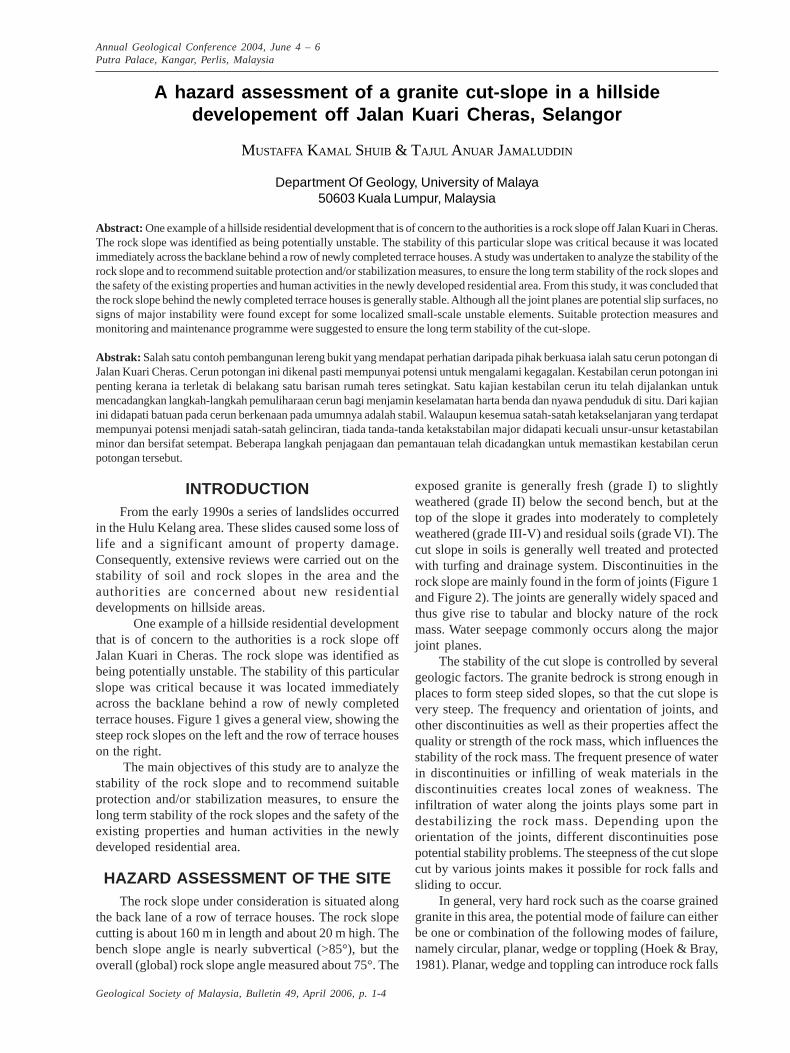
Based on the discontinuity survey (Figure 2), 4 majorjoint sets (namely J1, J2, J3, J4) plus one set of minor joint(J5) and a set of sheet joint (J6) were identified. Thenorthwesterly trending sub vertical major joint sets (J3and J4), are striking nearly parallel to the slope face, whilethe northeasterly trending sub vertical joints (J1 and J2)transect the slope surface almost at right angle. The sheetjoint dips gently (20-25°) to the NW (314°) into the slopeand thus are not likely to pose instability problems to therock slope.
ROCK SLOPE STABILITYASSESSMENT
The slope stability assessment adopted in this studyis to highlight any potential danger and the possible modeof rock slope failure that might be imposed on the existingslopes behind the terrace houses. Therefore, the visual
inspection method was used in conjunction with thestereoplots. All possible unstable sections of the slopes,especially the potential sliding planes and overhangs wereidentified. After the collection of discontinuity data, thegraphical method or kinematics slope stability ofdiscontinuity was used to assess the slope stability (Hoek& Bray, 1981).
Results of the kinematics stability analysis of the slopeare given in Figure 2. The shaded region (area boundedby the friction circle and slope face) in the stereoplot isthe considered a critical area. Results of the analysis(Figure 2) indicated that:a) The overall (global) rock slope is generally stable. No
sign of major instability was detected on the slopes.The orientations of the major joint sets is generallyfavourable to the slope orientation with the exceptionof the sub-vertical J4 joint set that may give rise totoppling.
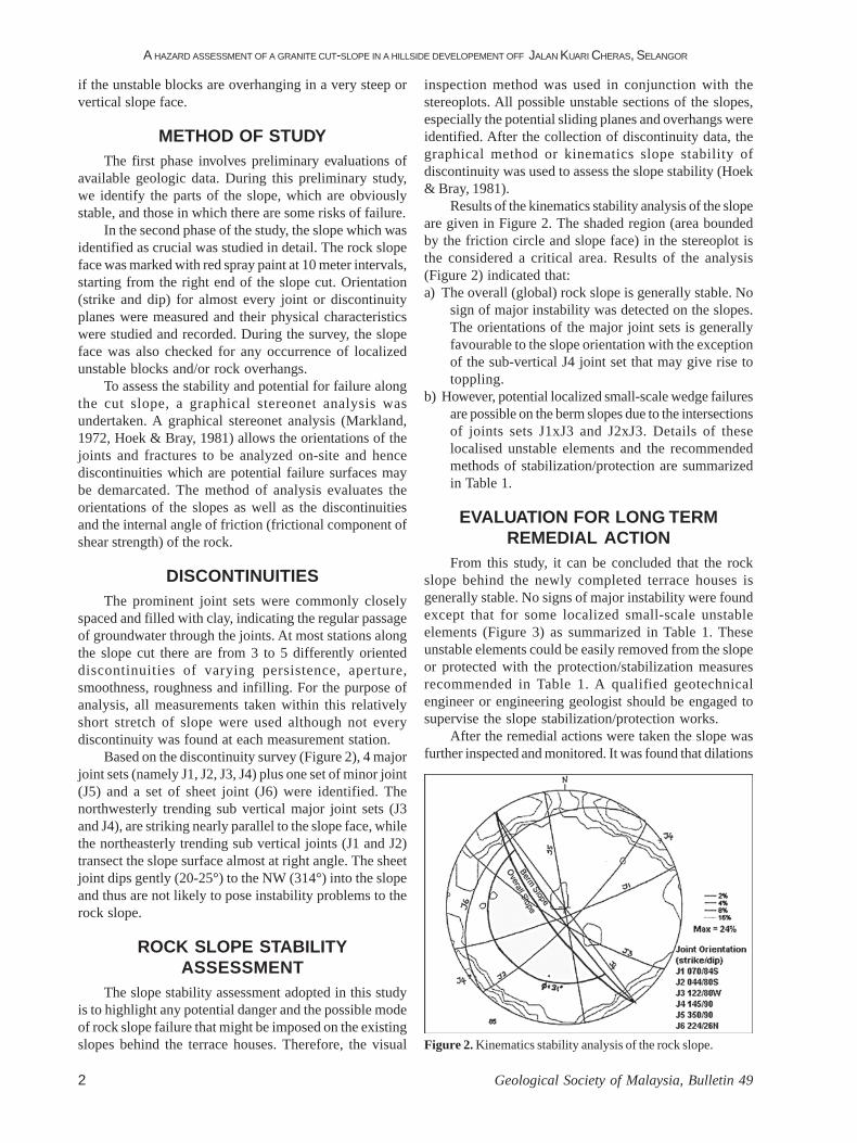
b) However, potential localized small-scale wedge failuresare possible on the berm slopes due to the intersectionsof joints sets J1xJ3 and J2xJ3. Details of theselocalised unstable elements and the recommendedmethods of stabilization/protection are summarizedin Table 1.
EVALUATION FOR LONG TERMREMEDIAL ACTION
From this study, it can be concluded that the rockslope behind the newly completed terrace houses isgenerally stable. No signs of major instability were foundexcept that for some localized small-scale unstableelements (Figure 3) as summarized in Table 1. Theseunstable elements could be easily removed from the slopeor protected with the protection/stabilization measuresrecommended in Table 1. A qualified geotechnicalengineer or engineering geologist should be engaged tosupervise the slope stabilization/protection works.
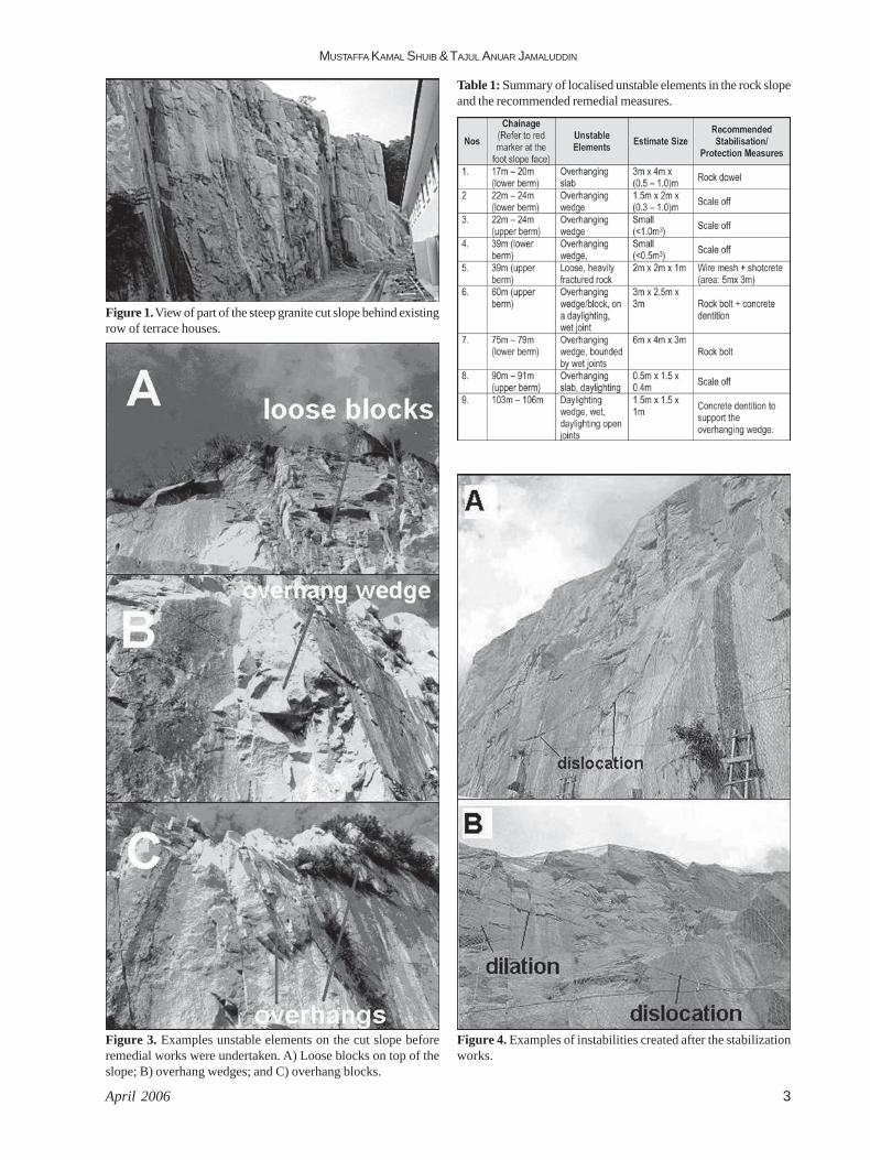
After the remedial actions were taken the slope wasfurther inspected and monitored. It was found that dilations
Figure 2. Kinematics stability analysis of the rock slope.
MUSTAFFA KAMAL SHUIB & TAJUL ANUAR JAMALUDDIN
April 2006 3
Figure 1. View of part of the steep granite cut slope behind existingrow of terrace houses.
Figure 3. Examples unstable elements on the cut slope beforeremedial works were undertaken. A) Loose blocks on top of theslope; B) overhang wedges; and C) overhang blocks.
Table 1: Summary of localised unstable elements in the rock slopeand the recommended remedial measures.
Figure 4. Examples of instabilities created after the stabilizationworks.
A HAZARD ASSESSMENT OF A GRANITE CUT-SLOPE IN A HILLSIDE DEVELOPEMENT OFF JALAN KUARI CHERAS, SELANGOR
Geological Society of Malaysia, Bulletin 494
Manuscipt received 30 March 2004Revised manuscript received 1 October 2004
hazards. This study illustrated the concern of theauthorities on the stability of cut slopes on hills whereexcavation has been carved out for the construction ofroads and houses. With adequate cut slope design, andimplementation of stabilization and protective measureson the cut slopes, including regular maintenance andmonitoring, failures on cut slopes may be mitigated andsubsequently, the need for costly rehabilitation andremediation measures may be avoided.
REFERENCESHOEK, E. AND BRAY, J.W., 1981. Rock slope engineering. 3rd
Ed. Inst. Mining & Metallurgy, London, 359p.MARKLAND, J.T., 1972. A useful technique for estimating
the stability of rock slopes when the rigid wedge slidetype of failure is expected. Imperial College RockMechanics Research, University of London. Reprints,n. 19.
and other signs of displacement had occurred along somejoints in certain blocks developed during and after thestabilization works (Figure 4). Further remedial worksshould be undertaken to ensure the long-term stability ofthe slope and in the meanwhile the slope should bemonitored regularly for signs of instability.
Monitoring slopes of concern is commonly an interim,precautionary measure while other action is being takento remedy the cause of concern so as to make the slopesafe over the long term. After the completion of theadditional remedial works, monitoring is no longernecessary but instead regular maintenance should becarried out.
CONCLUDING REMARKS -PLANNING CONSIDERATIONS
In any hillside development, the stability of cut slopeshould be maintained to prevent undesirable landslides
Top Related