


Languages
Pages
Legal


A DIGITAL LOGBOOK FOR COLLABORATION AND
CONCEPTUAL DESIGN
JAY MCCORMACK
University of Idaho
4.13.08
F I N A L R E P O R T
made possible through the support o f the NWACC (www.nwacc.org)
U n i v e r s i t y o f I d a h o • M e c h a n i c a l E n g i n e e r i n g • h t t p : / / w w w. w e b p a g e s . u i d a h o . e d u / ~ m c c o r m a c k / n w a c c /

Outlined in this report is the body of work and expenditures, as well as a summary of proposals
written, collaborations formed, and dissemination that resulted from this project.
1. WORK OVERVIEW AND ACCOMPLISHMENTS
This project aimed to 1) streamline and enhance the student design process and 2) extend the
effective reach of the design course instructor with respect to analyzing and providing feedback
on student design process. To accomplish these goals, a digital logbook system was integrated
into the sophomore mechanical engineering design course at the University of Idaho in the fall
of 2008 and the spring of 2009. The core of the digital logging system is a set of pen computers
that were used by students during the weekly design-build labs. Through this regular use of the
digital logbooks, several enhancements to the design experience and learning were prototyped.
The following is a summary of prototypes, experiments, and accomplishments made possible
by this project. More detail is about each is contained in subsequent sections.
• Collaboration between teammates with respect to design documentation was enabled in
a seamless digital form.
• Unproductive documentation was minimized through easy capture and sharing of data.
• Curriculum was developed to teach an authentic design knowledge reuse process based
on a foundation of understanding and modeling function as well as an approach to de-
sign in which function is synthesized before form.
• Preliminary connections were established between student’s digital notes and rapid pro-
totyping of specialized components to circumvent the lack of CAD training.
• Two approaches were prototyped to achieve sustainability of the curriculum with re-
spect to the instructor’s time and ability to provide feedback directly on design process
data - 1) an approach to student self-assessment and 2) automation modules that com-
pare project requirements to student design documentation.
• Conference and journal publications are in development that describe the design reuse
and automated design evaluation methods.
• A collaboration on future pen computer based teaching and research methods in design
was established with University of Maryland and Penn State University through the
J a y M c C o r m a c k! A D i g i t a l L o g b o o k f o r C o l l a b o r a t i o n a n d C o n c e p t u a l D e s i g n
1
submission of an initial proposal that leverages hardware, software, and techniques
from this project.
2. PEN COMPUTERS FOR DIGITAL DESIGN LOGGING
The Pulse Smartpen from Livescribe was selected as the hardware component of the digital log-
book system. The Smartpen is a pen computing device that uses the combination of traditional
ink and an integrated camera to record the user’s writing on Livescribe dot paper. The dot pa-
per looks like traditional logbook paper with small patterns of dots that enable the pen to de-
termine the location of the writing. Additionally, the Smartpen records audio data that is syn-
chronized with the captured text and diagrams. Once recorded, audio data can be replayed
through a paper interface or the audio and written data can be downloaded into purely digital
form. These digital notes can then be uploaded to a website for viewing by the notetaker or oth-
ers, depending on permissions and shared through popular outlets such as Facebook. For more
information on the digital Smartpen, see the official website which has several demo videos
(http://www.livescribe.com).
The simultaneous recording of audio data is useful in two ways: (1) it links what the student is
hearing to what the student is writing or sketching; and (2) the digitized journal pages can be
uploaded to a website, preserving the record and enabling access by student team members,
instructors or approved researchers. The Smartpen is a seamless design data collection instru-
ment in the disguise of a designer’s pen that can minimize unproductive logging in the form of
copying teammate notes and unnatural logging barriers in group work such as laptop comput-
ers. Both of these practices were observed in sophomore designers in an effort to improve de-
sign logging performance, but ultimately produced unproductive activities and groups.
The use of the pens as a design logbook tool was piloted by a senior level mechanical engineer-
ing design team that developed a slurry pump system in the summer of 2008 for an equipment
manufacturer in the waste water treatment industry. The pilot project provided valuable feed-
back in the areas of uploading and sharing the digital information captured. Through this pilot,
an initial online repository was created on the Livescribe website to hold and organize the data.
This approach allows for access to the synchronized drawing and audio entries captured during
the logging procedures using only a browser. Therefore, any team member can easily navigate
and return to their conceptual design data. Alternatively, a PDF version of the writing/drawing
content can be downloaded from the website for local storage and inclusion in reports and other
documents. Note that this pilot digital project logbook was subsequently removed form the on-
J a y M c C o r m a c k! A D i g i t a l L o g b o o k f o r C o l l a b o r a t i o n a n d C o n c e p t u a l D e s i g n
2

line repository to avoid confusion with the sophomore work which can now be observed at this
web address:
http://www.livescribe.com/cgi-bin/WebObjects/LDApp.woa/wa/MLSOverviewPage?sid=rN5Rr1NMc0f4
Currently, the University of Idaho account is the single largest contributer to the Livescribe
community.
The digital pens were incorporated into the student design process learning through a sequence
of design projects and design process lectures at the beginning of each semester. The sequence
of projects was designed to allow students to practice their increasing design skills while giving
the instructor and the students themselves the ability to assess and guide student performance.
It was critical to design the curriculum with the hardware in mind in order to provide a natural-
istic experience in which the hardware was not viewed as cumbersome or intrusive. The specific
design methodology was a function first approach that encouraged problem decomposition and
organized exploration of many ideas. The sequence of lecture and labs is outlined in Table 1.
The related lecture and lab materials are found in Appendix A.
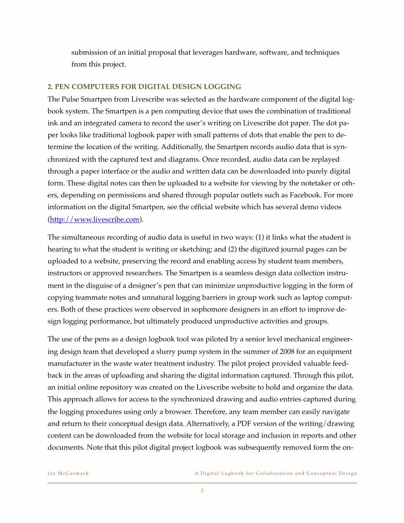
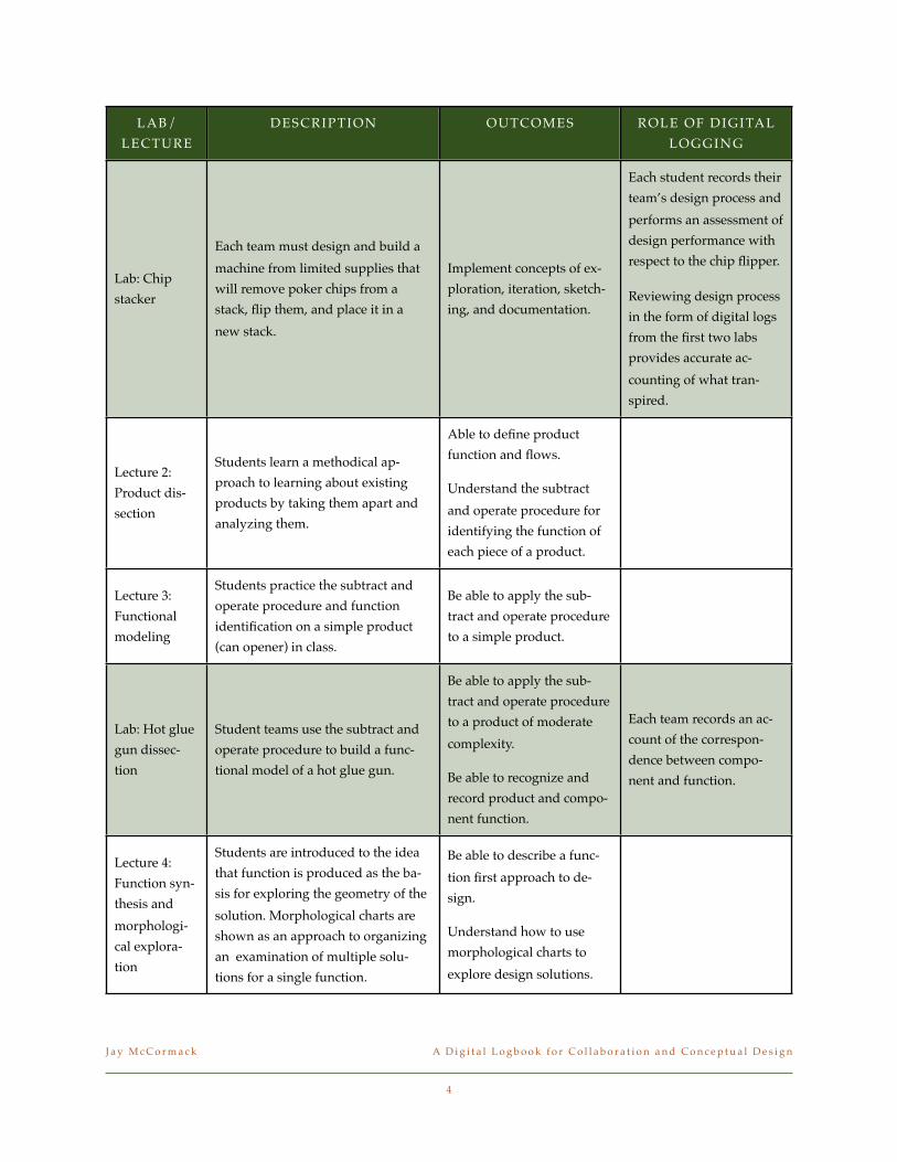
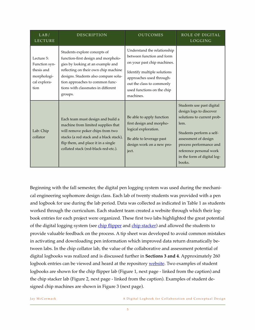
Table 1. The curriculum designed around and leveraging pen computers.
LAB/
LECTURE
DESCRIPTION OUTCOMES ROLE OF DIGITAL
LOGGING
Lab: Chip
flipper
Each team must design and build a
machine from limited supplies
(cardboard, hot glue, straws, etc.)
that will flip a poker chip with a
single human input.
Team icebreaker - getting to
know your teammates
Conquer digital logging
technical hurdles
Each student gets an in-
troduction to the hard-
ware and software as they
record their lab design
session. Recordings are
uploaded at the end of
class.
Lecture 1:
Design proc-
ess overview
Students learn the major steps in any
design process. The value of docu-
mentation, design iteration, explor-
ing many ideas, and sketching is
discussed by referencing the chip
flipper projects.
List and describe the major
steps of any design process.
Be able to discuss the im-
portance of following a
process
J a y M c C o r m a c k! A D i g i t a l L o g b o o k f o r C o l l a b o r a t i o n a n d C o n c e p t u a l D e s i g n
3
LAB/
LECTURE
DESCRIPTION OUTCOMES ROLE OF DIGITAL
LOGGING
Lab: Chip
stacker
Each team must design and build a
machine from limited supplies that
will remove poker chips from a
stack, flip them, and place it in a
new stack.
Implement concepts of ex-
ploration, iteration, sketch-
ing, and documentation.
Each student records their
team’s design process and
performs an assessment of
design performance with
respect to the chip flipper.
Reviewing design process
in the form of digital logs
from the first two labs
provides accurate ac-
counting of what tran-
spired.
Lecture 2:
Product dis-
section
Students learn a methodical ap-
proach to learning about existing
products by taking them apart and
analyzing them.
Able to define product
function and flows.
Understand the subtract
and operate procedure for
identifying the function of
each piece of a product.
Lecture 3:
Functional
modeling
Students practice the subtract and
operate procedure and function
identification on a simple product
(can opener) in class.
Be able to apply the sub-
tract and operate procedure
to a simple product.
Lab: Hot glue
gun dissec-
tion
Student teams use the subtract and
operate procedure to build a func-
tional model of a hot glue gun.
Be able to apply the sub-
tract and operate procedure
to a product of moderate
complexity.
Be able to recognize and
record product and compo-
nent function.
Each team records an ac-
count of the correspon-
dence between compo-
nent and function.
Lecture 4:
Function syn-
thesis and
morphologi-
cal explora-
tion
Students are introduced to the idea
that function is produced as the ba-
sis for exploring the geometry of the
solution. Morphological charts are
shown as an approach to organizing
an examination of multiple solu-
tions for a single function.
Be able to describe a func-
tion first approach to de-
sign.
Understand how to use
morphological charts to
explore design solutions.
J a y M c C o r m a c k! A D i g i t a l L o g b o o k f o r C o l l a b o r a t i o n a n d C o n c e p t u a l D e s i g n
4
LAB/
LECTURE
DESCRIPTION OUTCOMES ROLE OF DIGITAL
LOGGING
Lecture 5:
Function syn-
thesis and
morphologi-
cal explora-
tion
Students explore concepts of
function-first design and morpholo-
gies by looking at an example and
reflecting on their own chip machine
designs. Students also compare solu-
tion approaches to common func-
tions with classmates in different
groups.
Understand the relationship
between function and form
on your past chip machines.
Identify multiple solutions
approaches used through-
out the class to commonly
used functions on the chip
machines.
Lab: Chip
collator
Each team must design and build a
machine from limited supplies that
will remove poker chips from two
stacks (a red stack and a black stack),
flip them, and place it in a single
collated stack (red-black-red-etc.).
Be able to apply function
first design and morpho-
logical exploration.
Be able to leverage past
design work on a new pro-
ject.
Students use past digital
design logs to discover
solutions to current prob-
lem.
Students perform a self-
assessment of design
process performance and
reference personal work
in the form of digital log-
books.
Beginning with the fall semester, the digital pen logging system was used during the mechani-
cal engineering sophomore design class. Each lab of twenty students was provided with a pen
and logbook for use during the lab period. Data was collected as indicated in Table 1 as students
worked through the curriculum. Each student team created a website through which their log-
book entries for each project were organized. These first two labs highlighted the great potential
of the digital logging system (see chip flipper and chip stacker) and allowed the students to
provide valuable feedback on the process. A tip sheet was developed to avoid common mistakes
in activating and downloading pen information which improved data return dramatically be-
tween labs. In the chip collator lab, the value of the collaborative and assessment potential of
digital logbooks was realized and is discussed further in Sections 3 and 4. Approximately 260
logbook entries can be viewed and heard at the repository website. Two examples of student
logbooks are shown for the chip flipper lab (Figure 1, next page - linked from the caption) and
the chip stacker lab (Figure 2, next page - linked from the caption). Examples of student de-
signed chip machines are shown in Figure 3 (next page).
J a y M c C o r m a c k! A D i g i t a l L o g b o o k f o r C o l l a b o r a t i o n a n d C o n c e p t u a l D e s i g n
5

J a y M c C o r m a c k! A D i g i t a l L o g b o o k f o r C o l l a b o r a t i o n a n d C o n c e p t u a l D e s i g n
6
Figure 2. Example of student design
documentation from the chip stacker lab.
Figure 1. Example of student design
documentation from the chip flipper lab.
Figure 3. Student designed chip machines.
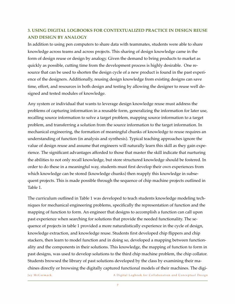
3. USING DIGITAL LOGBOOKS FOR CONTEXTUALIZED PRACTICE IN DESIGN REUSE
AND DESIGN BY ANALOGY
In addition to using pen computers to share data with teammates, students were able to share
knowledge across teams and across projects. This sharing of design knowledge came in the
form of design reuse or design by analogy. Given the demand to bring products to market as
quickly as possible, cutting time from the development process is highly desirable. One re-
source that can be used to shorten the design cycle of a new product is found in the past experi-
ence of the designers. Additionally, reusing design knowledge from existing designs can save
time, effort, and resources in both design and testing by allowing the designer to reuse well de-
signed and tested modules of knowledge.
Any system or individual that wants to leverage design knowledge reuse must address the
problems of capturing information in a reusable form, generalizing the information for later use,
recalling source information to solve a target problem, mapping source information to a target
problem, and transferring a solution from the source information to the target information. In
mechanical engineering, the formation of meaningful chunks of knowledge to reuse requires an
understanding of function (in analysis and synthesis). Typical teaching approaches ignore the
value of design reuse and assume that engineers will naturally learn this skill as they gain expe-
rience. The significant advantages afforded to those that master the skill indicate that nurturing
the abilities to not only recall knowledge, but store structured knowledge should be fostered. In
order to do these in a meaningful way, students must first develop their own experiences from
which knowledge can be stored (knowledge chunks) then reapply this knowledge in subse-
quent projects. This is made possible through the sequence of chip machine projects outlined in
Table 1.
The curriculum outlined in Table 1 was developed to teach students knowledge modeling tech-
niques for mechanical engineering problems, specifically the representation of function and the
mapping of function to form. An engineer that designs to accomplish a function can call upon
past experience when searching for solutions that provide the needed functionality. The se-
quence of projects in table 1 provided a more naturalistically experience in the cycle of design,
knowledge extraction, and knowledge reuse. Students first developed chip flippers and chip
stackers, then learn to model function and in doing so, developed a mapping between function-
ality and the components in their solutions. This knowledge, the mapping of function to form in
past designs, was used to develop solutions to the third chip machine problem, the chip collator.
Students browsed the library of past solutions developed by the class by examining their ma-
chines directly or browsing the digitally captured functional models of their machines. The digi-
J a y M c C o r m a c k! A D i g i t a l L o g b o o k f o r C o l l a b o r a t i o n a n d C o n c e p t u a l D e s i g n
7
tal notes from the teams original design of the chip machine could then be accessed to learn
about other critical information that was not apparent in the final built solution, such as manu-
facturability, constraints on the approach, and general guidance from the original designers.
This approach to learning design by analogy is in contrast to the traditional teaching technique
in which the instructor provided a carefully designed library of analogies from which the stu-
dent was to choose the “right” one.
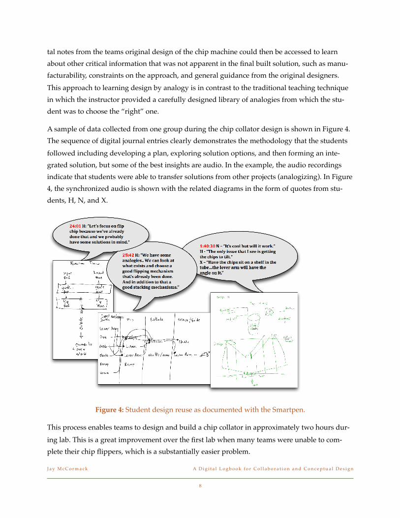
A sample of data collected from one group during the chip collator design is shown in Figure 4.
The sequence of digital journal entries clearly demonstrates the methodology that the students
followed including developing a plan, exploring solution options, and then forming an inte-
grated solution, but some of the best insights are audio. In the example, the audio recordings
indicate that students were able to transfer solutions from other projects (analogizing). In Figure
4, the synchronized audio is shown with the related diagrams in the form of quotes from stu-
dents, H, N, and X.
!
Figure 4: Student design reuse as documented with the Smartpen.
This process enables teams to design and build a chip collator in approximately two hours dur-
ing lab. This is a great improvement over the first lab when many teams were unable to com-
plete their chip flippers, which is a substantially easier problem.
J a y M c C o r m a c k! A D i g i t a l L o g b o o k f o r C o l l a b o r a t i o n a n d C o n c e p t u a l D e s i g n
8
4. EXTENDING EVALUATION INTO DESIGN PROCESS DATA - EXTENDING THE IN-
STRUCTOR’S EDUCATIONAL REACH
An assessment instrument was developed as part of this project to address the documents that
were be created by the students as part of their design projects. This project focuses on the ac-
tions surrounding the group design activities that are common to the conceptual design process
in a sophomore design course. This focus requires a more specific logbook assessment form that
highlights the critical elements of conceptual design process and the appropriate documenta-
tion. The basis for the assessment are the five basic steps of a conceptual design process (after
the definition of problem requirements). A rubric was developed to qualitatively indicate the
student’s level of success in documenting the team's design work. This rubric was used to guide
student performance in the use of their digital logbooks as well as by the instructor to assess in
process design artifacts from the digital capture without disturbing the flow of data in the de-
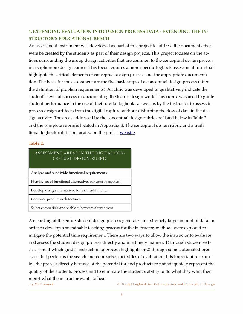
sign activity. The areas addressed by the conceptual design rubric are listed below in Table 2
and the complete rubric is located in Appendix B. The conceptual design rubric and a tradi-
tional logbook rubric are located on the project website.
Table 2.
ASSESSMENT AREAS IN THE DIGITAL CON-
CEPTUAL DESIGN RUBRIC
Analyze and subdivide functional requirements
Identify set of functional alternatives for each subsystem
Develop design alternatives for each subfunction
Compose product architectures
Select compatible and viable subsystem alternatives
A recording of the entire student design process generates an extremely large amount of data. In
order to develop a sustainable teaching process for the instructor, methods were explored to
mitigate the potential time requirement. There are two ways to allow the instructor to evaluate
and assess the student design process directly and in a timely manner: 1) through student self-
assessment which guides instructors to process highlights or 2) through some automated proc-
esses that performs the search and comparison activities of evaluation. It is important to exam-
ine the process directly because of the potential for end products to not adequately represent the
quality of the students process and to eliminate the student’s ability to do what they want then
report what the instructor wants to hear.J a y M c C o r m a c k! A D i g i t a l L o g b o o k f o r C o l l a b o r a t i o n a n d C o n c e p t u a l D e s i g n
9

A series of self-assessment questions were assigned to each team and each student at the con-
clusion of the chip collator project. These questions prompted the students to think reflectively
about how they performed in terms of design process strengths and areas for improvement. The
student’s reflective thinking was captured using the digital pens in order to allow students to
provide a presentation of their thinking through text, sketches, and audio. By providing a sum-
mary of their performance through the self-assessment, the student’s work can be reviewed in a
timely manner by the instructor. The assessment prompts are shown in Figure 5 and examples
of students’ reflection on process are linked from here:
• http://www.livescribe.com/cgi-bin/WebObjects/LDApp.woa/wa/MLSOverviewPage?sid=xhGXlCp8vqSx
• http://www.livescribe.com/cgi-bin/WebObjects/LDApp.woa/wa/MLSOverviewPage?sid=70BPqXLbDvZC
• http://www.livescribe.com/cgi-bin/WebObjects/LDApp.woa/wa/MLSOverviewPage?sid=8lF5VBjFW7J0
Figure 5. Self assessment questions after the chip collator design lab.
An alternative for making the assessment and evaluation of student design process a sustain-
able endeavor is to build in automation for extracting key information and comparing results to J a y M c C o r m a c k! A D i g i t a l L o g b o o k f o r C o l l a b o r a t i o n a n d C o n c e p t u a l D e s i g n
10
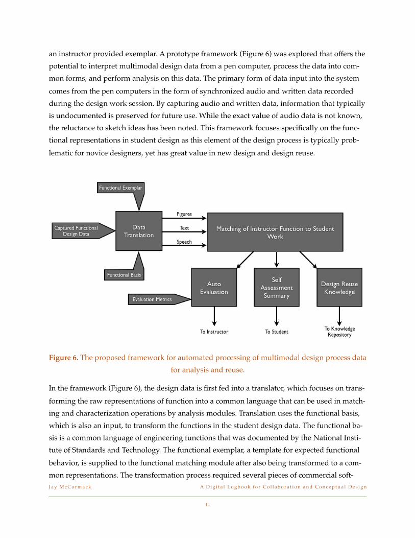
an instructor provided exemplar. A prototype framework (Figure 6) was explored that offers the
potential to interpret multimodal design data from a pen computer, process the data into com-
mon forms, and perform analysis on this data. The primary form of data input into the system
comes from the pen computers in the form of synchronized audio and written data recorded
during the design work session. By capturing audio and written data, information that typically
is undocumented is preserved for future use. While the exact value of audio data is not known,
the reluctance to sketch ideas has been noted. This framework focuses specifically on the func-
tional representations in student design as this element of the design process is typically prob-
lematic for novice designers, yet has great value in new design and design reuse.
Figure 6. The proposed framework for automated processing of multimodal design process data
for analysis and reuse.
In the framework (Figure 6), the design data is first fed into a translator, which focuses on trans-
forming the raw representations of function into a common language that can be used in match-
ing and characterization operations by analysis modules. Translation uses the functional basis,
which is also an input, to transform the functions in the student design data. The functional ba-
sis is a common language of engineering functions that was documented by the National Insti-
tute of Standards and Technology. The functional exemplar, a template for expected functional
behavior, is supplied to the functional matching module after also being transformed to a com-
mon representations. The transformation process required several pieces of commercial soft-
J a y M c C o r m a c k! A D i g i t a l L o g b o o k f o r C o l l a b o r a t i o n a n d C o n c e p t u a l D e s i g n
11
ware to translate raw data into text files for searching and comparison. Dragon Naturally
Speaking was purchased and used to translate audio files of student process. This software was
generally successful at translating audio files when background noise was minimized and the
system was trained on relevant vocabulary, which was extracted from the common function
terms. For object character recognition, the built-in Smartpen capabilities were leveraged. This
application was sufficient for testing but a stand-alone product with an API would likely be
needed for full application.
The matching process in the framework (Figure 6) compares the exemplar functions provided
by the instructor with those found in student work. In the most rudimentary application, this is
a search for a list of expected terms in a text representation of the student work. In the prototype
version, matches are also performed with respect to the structure of the instructors required
functions. The matching results can then passed into one or more of three modules: 1) the ex-
traction of design reuse knowledge, 2) application of evaluation metrics to design process, and
3) a process summary view for self-assessment. None of these modules have been realized as of
yet, but all three applications were shown to have value in this project. The development of
modules for self-assessment and design reuse (design-by-analogy) will enhance the student ex-
perience as described previously in this report. The evaluation of student functional models is
also an exciting and beneficial research project for students and faculty. This framework will en-
able new learning about the way that engineering design and engineering design of function is
taught specifically by leveraging temporal data that is capturing in the synchronized audio-text
data from pen computers.
5. CONNECTING DIGITAL LOGGING TO RAPID PROTOTYPING
One project goal that was not fully realized was establishing a connection between digital log-
ging and CAD tools where a direct transfer of data could save time in moving from conceptual
design to detailed design, then manufacturing. It was learned by the PI that a substantial num-
ber (approximately 75%) of the sophomores in the design course had not yet had the introduc-
tory solid modeling class. Any connection to a CAD tool would be useless for them as they
struggled with basic concepts of computer aided design. Instead, a simple protocol was devel-
oped for connecting these students with rapid prototyping without the CAD experience. Stu-
dents could submit requests to have parts printed on the department’s 3D printer as part of
their later design projects. In the final project in the fall semester, students created crack welding
robots which were powered by AC blender motors. Because substantial gearing was required by
most, a design form was developed to specify the dimensions of the desired gears. Once speci-
J a y M c C o r m a c k! A D i g i t a l L o g b o o k f o r C o l l a b o r a t i o n a n d C o n c e p t u a l D e s i g n
12
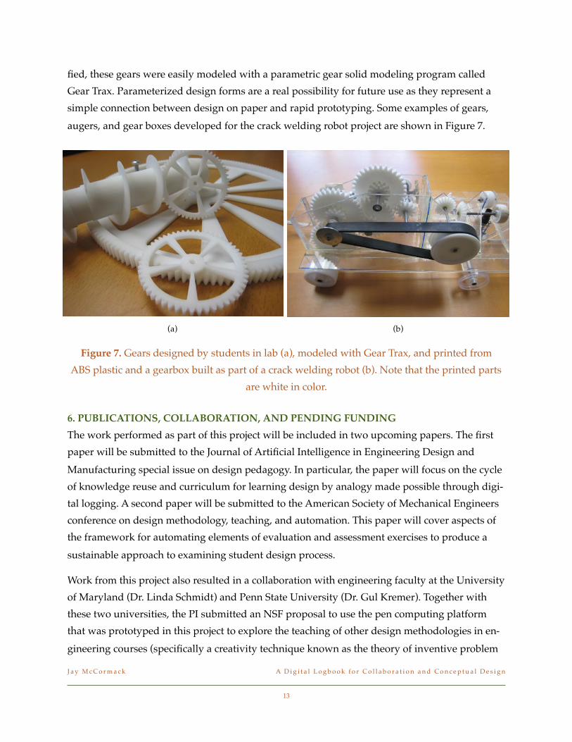
fied, these gears were easily modeled with a parametric gear solid modeling program called
Gear Trax. Parameterized design forms are a real possibility for future use as they represent a
simple connection between design on paper and rapid prototyping. Some examples of gears,
augers, and gear boxes developed for the crack welding robot project are shown in Figure 7.
6. PUBLICATIONS, COLLABORATION, AND PENDING FUNDING
The work performed as part of this project will be included in two upcoming papers. The first
paper will be submitted to the Journal of Artificial Intelligence in Engineering Design and
Manufacturing special issue on design pedagogy. In particular, the paper will focus on the cycle
of knowledge reuse and curriculum for learning design by analogy made possible through digi-
tal logging. A second paper will be submitted to the American Society of Mechanical Engineers
conference on design methodology, teaching, and automation. This paper will cover aspects of
the framework for automating elements of evaluation and assessment exercises to produce a
sustainable approach to examining student design process.
Work from this project also resulted in a collaboration with engineering faculty at the University
of Maryland (Dr. Linda Schmidt) and Penn State University (Dr. Gul Kremer). Together with
these two universities, the PI submitted an NSF proposal to use the pen computing platform
that was prototyped in this project to explore the teaching of other design methodologies in en-
gineering courses (specifically a creativity technique known as the theory of inventive problem
J a y M c C o r m a c k! A D i g i t a l L o g b o o k f o r C o l l a b o r a t i o n a n d C o n c e p t u a l D e s i g n
13
(a) (b)
Figure 7. Gears designed by students in lab (a), modeled with Gear Trax, and printed from
ABS plastic and a gearbox built as part of a crack welding robot (b). Note that the printed parts
are white in color.

solving). The pen computing curriculum and hardware software protocols will be adopted by
undergraduate and graduate courses at the cooperating universities. (NSF proposal 0910239 -
Collaborative Research: Testing Ideation Processes in Engineering (TIPE))
7. EXPENDITURES
Project funds have been applied as follows.
SalariesJay McCormack! ! $2,500Steve Beyerlein! ! $1,500Technical assistant! ! $1,500
Fringe! ! ! ! $880.27
Hardware/Software20 pen computers (1 GB)! $2,999.00Dragon Naturally Speaking! $209.94External HD (2)! ! $258.00
SuppliesAdditional ink!! (40)! $23.80!Additional notebooks (16)! $79.80
ShippingAll shipping costs! ! $27.00
Total! ! ! ! $9,977.81
• The project was also supported through the donation of three computers for use with the
pens in the lab environment.
• The hard drives allowed pen data to be backed up and transferred from the lab to the in-
structor and TA computers.
• Dragon Naturally Speaking was used to enable the evaluation framework and the searching
for keywords (functions) in the student design process.
• VMware Fusion was purchased through another budget to enable the Livescribe software to
work on Macintosh computers. This was erroneously reported as part of this budget during
the interim report.
J a y M c C o r m a c k! A D i g i t a l L o g b o o k f o r C o l l a b o r a t i o n a n d C o n c e p t u a l D e s i g n
14

APPENDIX A
Curriculum material for teaching design process and design reuse supported through the use of pen computer log-
books. The material in this appendix is presented in the order in which it is used which is also the order in which it
was presented in Table 1.
J a y M c C o r m a c k! A D i g i t a l L o g b o o k f o r C o l l a b o r a t i o n a n d C o n c e p t u a l D e s i g n
1

Lab - Chip Flipper
Objectives
Practice design in a team environment
Get to know your teammates
Agenda
Lab rules (5 min)
Introduction to digital logging (5 min)
Design, build, and demonstrate chip flipper (90 min)
Upload digital logbook entries (15 min)
Design and Build Chip FlipperGoal: Design and build your mechanism making full use of all individuals on your team. You may approach this teamwork project by dividing or sharing any responsibilities however you wish.
Materials: Corrugated cardboard, paper clips, paper, 3x5 cards, rubber bands, tape, glue, popsicle sticks, toothpicks, poker chips, straws.
Function of the chip flipper:
• The mechanism must flip a poker chip from one side to the other side.
• The chip must begin with nothing on top of it (except air) and finish with nothing on top of it.
• The chip must begin within a circle drawn on the mechanism. The starting circle should have a diameter no more than 1/8” larger than the poker chip.
• The chip must finish within a circle drawn on the mechanism. The finishing circle should have a diameter no more than 1/8” larger than the poker chip.
• The mechanism must have a footprint no larger than 10” square.
• The mechanism must be less than 6” tall.
Operation of the chip flipper:
• The operator must not touch the chip during the operation of the mechanism.
• The operator may move one control during the operation of the mechanism.
• The mechanism must remain fixed to the table during the operation. It may be held down by a teammate.
• The chip must reliably be flipped and properly placed by an untrained, clumsy, “slow-to-figure-it-out” sort of fellow.
J a y M c C o r m a c k! A D i g i t a l L o g b o o k f o r C o l l a b o r a t i o n a n d C o n c e p t u a l D e s i g n
2

Action Items
Link each of your teams member!s digital logbook entry from the team website. Put all of the entries under a single header (see below for example). Email a link to your web-site to me before class tomorrow.
Sample webpage format
Lab 1 - Chip flipperLink to Bryce!s logbook entryLink to Jon!s logbook entryLink to Brittany!s logbook entry
J a y M c C o r m a c k! A D i g i t a l L o g b o o k f o r C o l l a b o r a t i o n a n d C o n c e p t u a l D e s i g n
3

Lecture - Design Process Overview
Objectives
Discuss the reasons why following a design process is important.
Be able to describe the key elements of the design process.
Agenda
Motivate the need and benefits of process. Fill out chart. (5 min)
Describe and discuss each step of the basic design process (activities and results). (15 min)
Enumerate and discuss the common threads throughout a design process. (5 min)
Introduction to assessment (5 min)
Group work: assess performance in lab 1 (15 min)
Motivation for Using Good Design Process
Basic Product Development Process - Capstone design process website
Time
J a y M c C o r m a c k! A D i g i t a l L o g b o o k f o r C o l l a b o r a t i o n a n d C o n c e p t u a l D e s i g n
4
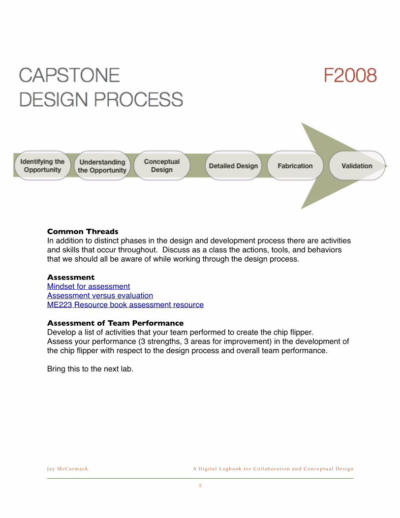
Common Threads
In addition to distinct phases in the design and development process there are activities and skills that occur throughout. Discuss as a class the actions, tools, and behaviors that we should all be aware of while working through the design process.
Assessment
Mindset for assessmentAssessment versus evaluationME223 Resource book assessment resource
Assessment of Team Performance
Develop a list of activities that your team performed to create the chip flipper.Assess your performance (3 strengths, 3 areas for improvement) in the development of the chip flipper with respect to the design process and overall team performance.
Bring this to the next lab.
J a y M c C o r m a c k! A D i g i t a l L o g b o o k f o r C o l l a b o r a t i o n a n d C o n c e p t u a l D e s i g n
5

Lab - Chip StackerObjectives
Improve design performance through acting on assessment plan.
Improve documentation practices in conceptual design.
Agenda
Chip flipper show and tell - report on self-assessment (10 min)
Chip stacker introduction and scheduling (10 min)
Design, build, and demonstrate chip flipper (90 min)
Design and Build Chip Flipper1. Develop an estimate of your schedule for the lab period. Include the following items
conceptual design, fabrication, assessment, and redesign (and re-fabrication).2. Develop and document multiple concepts through several iterations.3. Select the preferred concept based on team discussion and assessment.4. Develop a complete drawing of your final design (before fabrication).
MaterialsCorrugated cardboard, paper clips, paper, 3x5 cards, rubber bands, tape, glue, popsicle sticks, toothpicks
Function of the Chip-Stacker
• The mechanism must flip and re-stack 6 poker chips.
• The chips must begin in a stack with nothing except air above the stack for 6”.
• The chips must begin in a stacked position that is horizontal to the work table surface.
• The chips must finish in a stack with no part of the mechanism touching the top chip in the stack.
• The top of the finishing stack must be no more than 1” vertically lower than the bottom of the starting stack.
• The stack of chip must begin within a circle drawn on the mechanism. The starting circle should have a diameter no more than 1/8” larger than the poker chip.
• The chips may be removed from the top or the bottom of the starting stack.
• The chips must be flipped one at a time. (Take the chip from the stack, flip it, get it on the other stack, and then do another chip.)
• The chips must finish within a circle drawn on the mechanism. The finishing circle should have a diameter no more than 1/8” larger than the poker chip. The chips must finish in a position horizontal to the work table surface.
• The entire mechanism must have a footprint no larger than 4” x 6”.
J a y M c C o r m a c k! A D i g i t a l L o g b o o k f o r C o l l a b o r a t i o n a n d C o n c e p t u a l D e s i g n
6
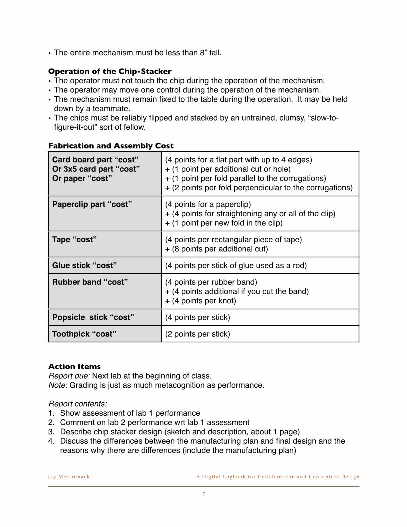
• The entire mechanism must be less than 8” tall.
Operation of the Chip-Stacker
• The operator must not touch the chip during the operation of the mechanism.
• The operator may move one control during the operation of the mechanism.
• The mechanism must remain fixed to the table during the operation. It may be held down by a teammate.
• The chips must be reliably flipped and stacked by an untrained, clumsy, “slow-to-figure-it-out” sort of fellow.
Fabrication and Assembly Cost
Card board part “cost”Or 3x5 card part “cost”Or paper “cost”
Paperclip part “cost”
Tape “cost”
Glue stick “cost”
Rubber band “cost”
Popsicle stick “cost”
Toothpick “cost”
(4 points for a flat part with up to 4 edges) + (1 point per additional cut or hole) + (1 point per fold parallel to the corrugations) + (2 points per fold perpendicular to the corrugations)
(4 points for a paperclip)+ (4 points for straightening any or all of the clip) + (1 point per new fold in the clip)
(4 points per rectangular piece of tape) + (8 points per additional cut)
(4 points per stick of glue used as a rod)
(4 points per rubber band) + (4 points additional if you cut the band) + (4 points per knot)
(4 points per stick)
(2 points per stick)
Action ItemsReport due: Next lab at the beginning of class.Note: Grading is just as much metacognition as performance.
Report contents:
1. Show assessment of lab 1 performance2. Comment on lab 2 performance wrt lab 1 assessment3. Describe chip stacker design (sketch and description, about 1 page)4. Discuss the differences between the manufacturing plan and final design and the
reasons why there are differences (include the manufacturing plan)
J a y M c C o r m a c k! A D i g i t a l L o g b o o k f o r C o l l a b o r a t i o n a n d C o n c e p t u a l D e s i g n
7

5. Assess lab 2 performance (3 strengths, 3 areas of improvement - be sure that your assessment is complete)
J a y M c C o r m a c k! A D i g i t a l L o g b o o k f o r C o l l a b o r a t i o n a n d C o n c e p t u a l D e s i g n
8
Lecture - Introduction to Understanding
the Opportunity & Product Teardown
Objectives
Establish the motivation for product dissection and functional modeling.
Introduce the fundamental concepts of modeling function.
Agenda
Notes about yesterday (5 min)
Building your understanding - technology, people, and products (5 min)
Product dissection procedure (10 min)
Concept introduction: functions and flows (15 min)
In class exercise (15 min)
NotesHow much time did you allocate for design on paper? What is prototyping? What does it buy you?
Overview of Understanding the Opportunity
• After a business opportunity is identified.
• Concludes with the development of specifications and the inception of conceptual de-sign.
• Activities focus on growing an understanding of people, products, and technology.
• Need to grow our representation (modeling) skills to capture our knowledge.
Technology
• Research and discovery of new science, etc.
• Building an understanding of the fundamental science behind a product.
People
• Identify and understand stakeholders.
• Observe and model the user experience.
• Experiential design, user-centered design, and empathy
• Value based design, human factors, usability, ergonomics
J a y M c C o r m a c k! A D i g i t a l L o g b o o k f o r C o l l a b o r a t i o n a n d C o n c e p t u a l D e s i g n
9

Products
• Study relevant products in order to grow knowledge about
• Competitors, past revisions, comparable technology, and inspirational de-signs.
• Knowledge is captured and transmitted by establishing models of
• Geometry, function, force/energy, aesthetics, mathematical behavior
Product Teardown (aka Product Dissection)See product teardown resource
Force Flow DiagramsSee force flow resource
J a y M c C o r m a c k! A D i g i t a l L o g b o o k f o r C o l l a b o r a t i o n a n d C o n c e p t u a l D e s i g n
10
09-02-08!
11
Product Teardown
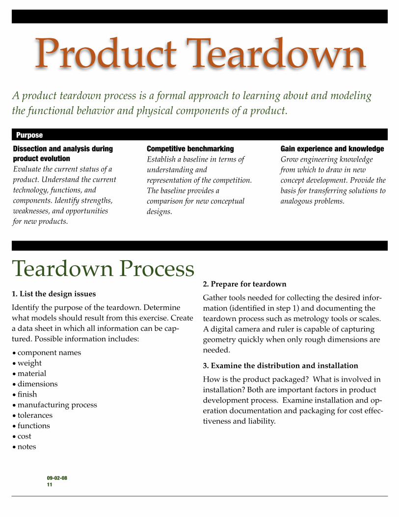
Teardown Process 1. List the design issues
Identify the purpose of the teardown. Determine
what models should result from this exercise. Create
a data sheet in which all information can be cap-
tured. Possible information includes:
• component names
• weight
• material
• dimensions
• finish
• manufacturing process
• tolerances
• functions
• cost
• notes
2. Prepare for teardown
Gather tools needed for collecting the desired infor-
mation (identified in step 1) and documenting the
teardown process such as metrology tools or scales.
A digital camera and ruler is capable of capturing
geometry quickly when only rough dimensions are
needed.
3. Examine the distribution and installation
How is the product packaged? What is involved in
installation? Both are important factors in product
development process. Examine installation and op-
eration documentation and packaging for cost effec-
tiveness and liability.
A product teardown process is a formal approach to learning about and modeling
the functional behavior and physical components of a product.
Dissection and analysis during
product evolution
Evaluate the current status of a
product. Understand the current
technology, functions, and
components. Identify strengths,
weaknesses, and opportunities
for new products.
Competitive benchmarking
Establish a baseline in terms of
understanding and
representation of the competition.
The baseline provides a
comparison for new conceptual
designs.
Gain experience and knowledge
Grow engineering knowledge
from which to draw in new
concept development. Provide the
basis for transferring solutions to
analogous problems.
Purpose"

12!
09-02-08
4. Disassemble, measure, analyze data, and model
by assemblies
Analyze and measure the complete product first.
Coordinate disassembly with measurement, experi-
mentation, and modeling. Take apart assembly (be
clear about what non-destructive disassembly is ac-
ceptable and needed) . Take pictures of each compo-
nent, major assembly, and photograph the product in
an exploded view. Take measurements to complete
data sheet. Be sure that all data models and pictures
are referenced in the data sheet.
5. Create system models
Product assembly and geometric model
When photos do not provide sufficient detail, geo-
metric models can be created as part of the teardown
learning exercise.
Force flow diagrams
Track the movement of forces through a product.
Used to expose opportunities for component combi-
nations, highlights opportunities to improve product.
See the resource on force flow diagrams.
Functional models
Capture the behavior of of a product by focusing on
what it does not how it does it (which is the role of
geometry). Functional models demonstrate the
product’s transformation and transference of materi-
als, information, and energy from an input state into
the desired functions. See the resource on generating
functional models with the subtract and operate
procedure.

Lecture - Function Modeling - Subtract &
Operate Procedure
Objectives
Introduce and practice with identifying functions and flows.
Agenda
Review of force flow (15 min)
Functions and flows (10 min)
Subtract and operate (10 min)
Subtract and operate example (15 min)
Force Flow - Can Opener Tips:
• All components are a circle (node) - interactions are arrows
• If you are lost, try creating all of the nodes first
• It will be messy on the first pass
• You don’t need to name the flows... each one is a force
Review the force flow diagram of can openerLook for potential component combinations from1. Relative motion of components2. Parallel componentsMake a sketch of a can opener with a reduced number of components.
When designing and discussing complex systems, how do you manage the team when there is lots to do and lots of people to do it?
Functions and Flows Building a model of product behavior/function requires practice at concisely stating function and recognizing flows.
Flow - an input/output to a system that can be classified as material, energy, or information
Function - a transformation between a set of inputs flows to a set of output flows. Verbal descriptions of function take on a “verb-noun” structure where the noun refers to the
S E Q U O I A C L U B
!
13

flow and the verb is the action performed by the function.
Black box - The first step in developing a system model is to build a black box model of an entire system by 1) identifying the system boundary, 2) identifying input/output flows, and 3) defining the system (product) function.
Subtract and Operate Procedure See S&O resource
Subtract & Operate Exercise - Can Opener Using the component decomposition from the can opener, deduce the function of each component from the can opener.
Action Items For lab tomorrow, each team needs to bring:
• a digital camera
• a printout of the Product Teardown procedure, Force Flow Diagram procedure, and Subtract and Operate Procedure.
14!
09-02-08
09-09-08!
15
Functional Modeling: Sub-tract & Operate Procedure
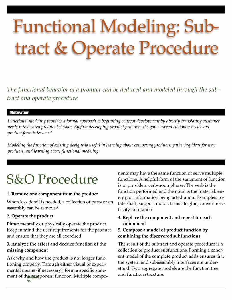
S&O Procedure1. Remove one component from the product
When less detail is needed, a collection of parts or an
assembly can be removed.
2. Operate the product
Either mentally or physically operate the product.
Keep in mind the user requirements for the product
and ensure that they are all exercised.
3. Analyze the effect and deduce function of the
missing component
Ask why and how the product is not longer func-
tioning properly. Through either visual or experi-
mental means (if necessary), form a specific state-
ment of the component function. Multiple compo-
nents may have the same function or serve multiple
functions. A helpful form of the statement of function
is to provide a verb-noun phrase. The verb is the
function performed and the noun is the material, en-
ergy, or information being acted upon. Examples: ro-
tate shaft, support motor, translate glue, convert elec-
tricity to rotation
4. Replace the component and repeat for each
component
5. Compose a model of product function by
combining the discovered subfunctions
The result of the subtract and operate procedure is a
collection of product subfunctions. Forming a coher-
ent model of the complete product adds ensures that
the system and subassembly interfaces are under-
stood. Two aggregate models are the function tree
and function structure.
The functional behavior of a product can be deduced and modeled through the sub-
tract and operate procedure
Functional modeling provides a formal approach to beginning concept development by directly translating customer
needs into desired product behavior. By first developing product function, the gap between customer needs and
product form is lessened.
Modeling the function of existing designs is useful in learning about competing products, gathering ideas for new
products, and learning about functional modeling.
Motivation"
16!
09-09-08
handle 1
handle 2
crank
wheelblade
support
shaft
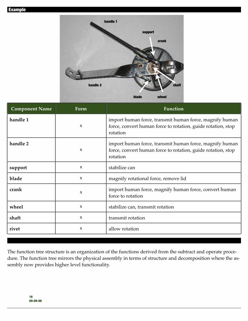
The function tree structure is an organization of the functions derived from the subtract and operate proce-
dure. The function tree mirrors the physical assembly in terms of structure and decomposition where the as-
sembly now provides higher level functionality.
Function treesExample
Component Name Form Function
handle 1X
import human force, transmit human force, magnify human
force, convert human force to rotation, guide rotation, stop
rotation
handle 2X
import human force, transmit human force, magnify human
force, convert human force to rotation, guide rotation, stop
rotation
support X stabilize can
blade X magnify rotational force, remove lid
crankX
import human force, magnify human force, convert human
force to rotation
wheel X stabilize can, transmit rotation
shaft X transmit rotation
rivet X allow rotation

To complete the functional model (also known as a function structure), first identify the material, energy,
and information inputs and outputs from the system. The functions identified from subtract and operate,
can now be arranged to model the transformation and transference of materials, energy, and information as
seen in the product.
There is formal list of functions and flows that all products employ to provide the desired behavior. Don’t
feel constrained by the list. Instead use it as an inspirational word bank.
Common flows!
Material: solid, liquid, gas, human
Energy: human force, human motion, chemical, electrical, electromagnetic, hydraulic, magnetic, force,
torque, linear motion, rotational motion
Information: tactile, olfactory, auditory, taste, visual, control
Common functions !
Guide, translate, rotate, transmit, import, export
Support, stop, stabilize
Connect, couple, mix
Branch, refine, distribute, dissipate, separate, re-
move
Provide, store, supply, extract
Control magnitude, actuate, regulate, change
Convert
Signal, sense, indicate, display, measure
Function structures!
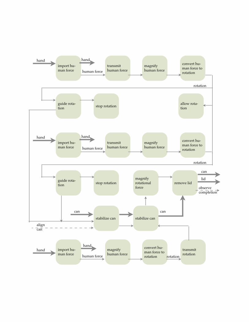
import hu-man force
transmit human force
magnify human force
convert hu-man force to rotation
guide rota-tion
stop rotation
stabilize can
magnify human force
remove lid
import hu-man force
magnify rotational force
convert hu-man force to rotation
transmit rotation
allow rota-tion
align can
hand hand
human force
rotation
can
handhand
human force rotation
can
stabilize can
can
lid
import hu-man force
transmit human force
magnify human force
convert hu-man force to rotation
guide rota-tion
stop rotation
hand hand
human force
rotation
observe completion

Lab - Hot Glue Gun Dissection
Objectives
Put teardown and subtract & operate procedures into practice.
Create force flow diagrams and functional models.
Agenda
Chip stacker show and tell - report on self-assessment (10 min)
Introduction (10 min)
Perform dissection (90 min)
Glue Gun DissectionEach team will dissect one hot glue gun. Refer to the product teardown, subtract and operate, and force flow diagram resources to perform this lab.
We will use the glue guns again on a later project and they will need to operate. You break !em, you bought !em. If there is something that seems like it will break, call for a mentor.
Deliverables
• A table of component name, form, and function for each component
• The form should be captured with a picture. Providing a sense of scale is also beneficial.
• Remember that each component can have more than one function.
• A hierarchical (tree) model of function including lowest level functions and logical groupings of functions into larger functional groups.
• A black box model of function and flows
• A series of images that show the assembly in tact and an exploded image of the prod-uct
• The objective is to show someone how all of the pieces fit together including pack-aging.
Discussion Questions1. Inspect the hot glue gun on the mentor table (you might want to take a picture). Cre-
ate a force flow diagram of this hot glue gun as well and compare it to the force flow diagram of your hot glue gun. What components were eliminated/combined? Justify the changes by referring to the force flow diagrams. What other components can be combined/eliminated in your hot glue gun?
2. What effects (good and bad) did the changes in component design have on manu-facturing, assembly, and product performance?
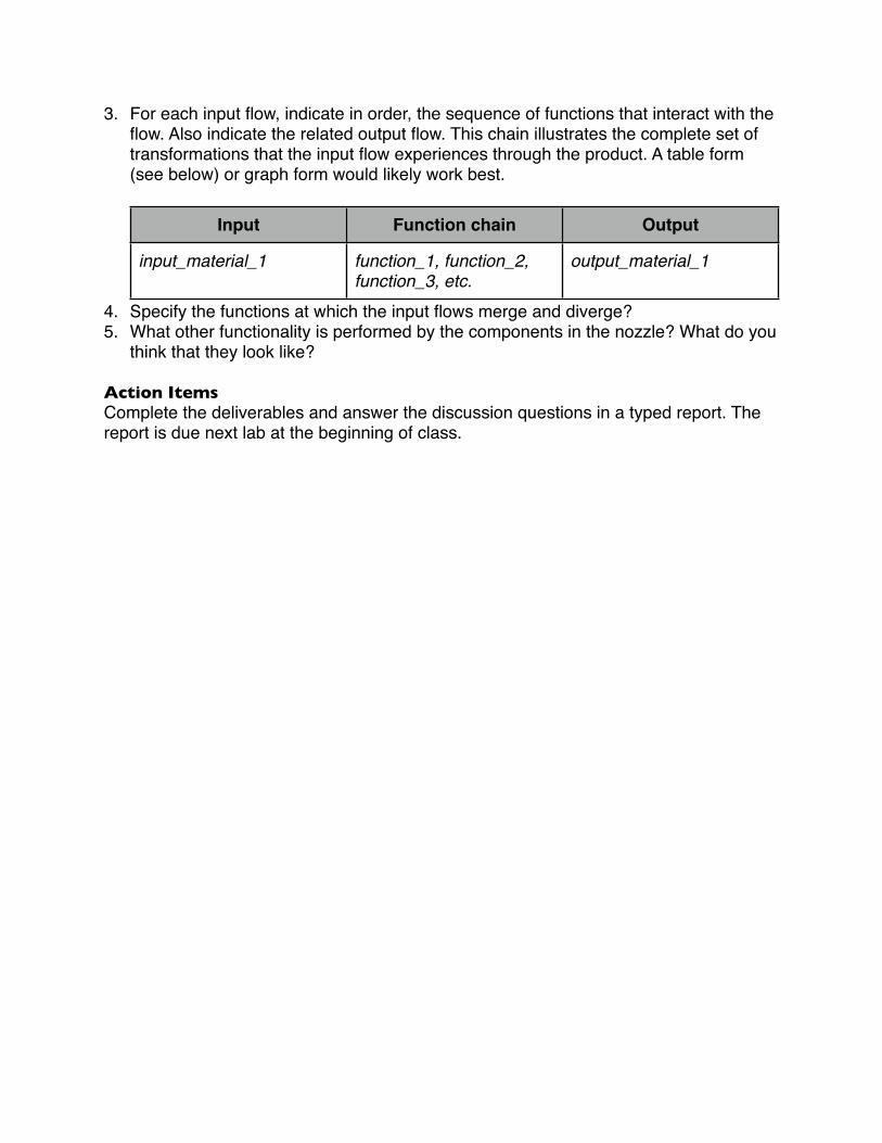
3. For each input flow, indicate in order, the sequence of functions that interact with the flow. Also indicate the related output flow. This chain illustrates the complete set of transformations that the input flow experiences through the product. A table form (see below) or graph form would likely work best.
Input Function chain Output
input_material_1 function_1, function_2, function_3, etc.
output_material_1
4. Specify the functions at which the input flows merge and diverge?5. What other functionality is performed by the components in the nozzle? What do you
think that they look like?
Action Items
Complete the deliverables and answer the discussion questions in a typed report. The report is due next lab at the beginning of class.
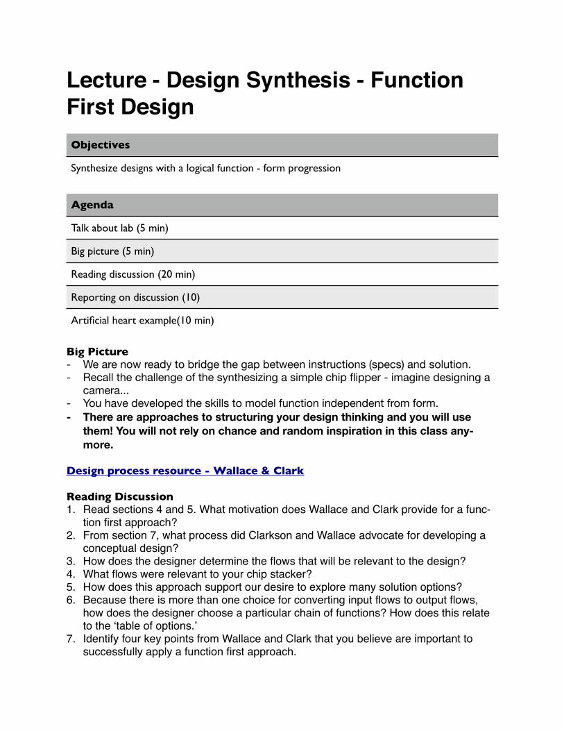
Lecture - Design Synthesis - Function
First Design
Objectives
Synthesize designs with a logical function - form progression
Agenda
Talk about lab (5 min)
Big picture (5 min)
Reading discussion (20 min)
Reporting on discussion (10)
Artificial heart example(10 min)
Big Picture- We are now ready to bridge the gap between instructions (specs) and solution.- Recall the challenge of the synthesizing a simple chip flipper - imagine designing a
camera...- You have developed the skills to model function independent from form.
- There are approaches to structuring your design thinking and you will use
them! You will not rely on chance and random inspiration in this class any-
more.
Design process resource - Wallace & Clark
Reading Discussion1. Read sections 4 and 5. What motivation does Wallace and Clark provide for a func-
tion first approach?2. From section 7, what process did Clarkson and Wallace advocate for developing a
conceptual design?3. How does the designer determine the flows that will be relevant to the design?4. What flows were relevant to your chip stacker?5. How does this approach support our desire to explore many solution options?6. Because there is more than one choice for converting input flows to output flows,
how does the designer choose a particular chain of functions? How does this relate to the !table of options."
7. Identify four key points from Wallace and Clark that you believe are important to successfully apply a function first approach.

Lecture - Design Synthesis II
Objectives
Synthesize designs with a logical function - form progression
Agenda
Review process (5 min)
An alternate view - the artificial heart example (10 min)
Identify functions and solutions for past chip machines (25 min)
Discuss chip machine questions (10 min)
Overview of Clarkson and Wallace Process8. Identify overall function (see the specs)9. Decompose overall function into smaller functions10.Arrange the functions in a logical sequence to form a system and/or process function
structure11. Identify multiple solutions for each function (table of options, morphological chart)12.Compose architectures from selected combination13.Add details to enable uniform evaluation14.Select concept based on likelihood of specs fulfillment
Notes:Design exploration can include function, flows, or form
Model chip machines
• In groups of 3 or 4, take a chip machine from the box
• Playact the flow of the chip and the human force (motion) to produce a function struc-ture.
• What functions are most common?
• Where do flows interface?
• With a few other teams, identify multiple physical solutions for three common func-tions.
• Which functions were obvious at the beginning of these design projects? Which ones were more subtle? How did that play out in the timing and nature of the solutions?
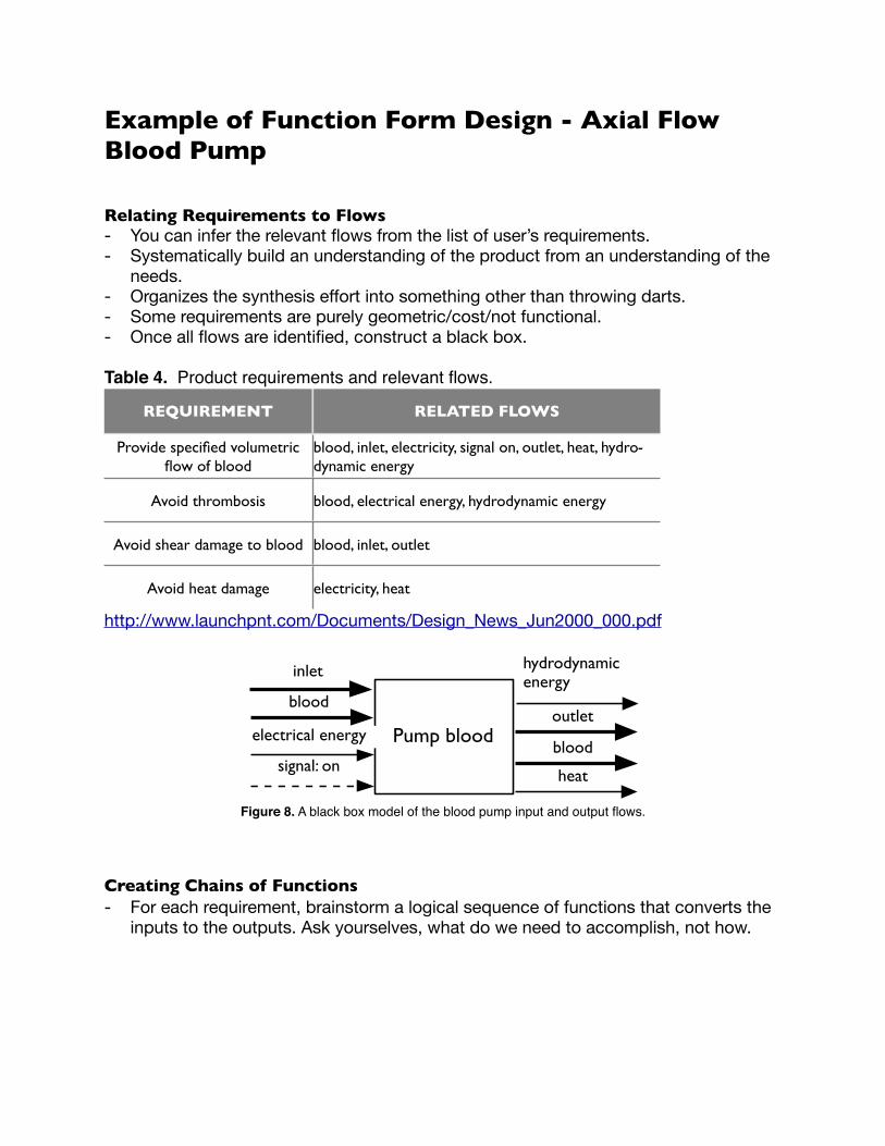
Example of Function Form Design - Axial Flow Blood Pump
Relating Requirements to Flows- You can infer the relevant flows from the list of user’s requirements.- Systematically build an understanding of the product from an understanding of the
needs.- Organizes the synthesis effort into something other than throwing darts.- Some requirements are purely geometric/cost/not functional.- Once all flows are identified, construct a black box.
Table 4. Product requirements and relevant flows.
REQUIREMENT RELATED FLOWS
Provide specified volumetric flow of blood
blood, inlet, electricity, signal on, outlet, heat, hydro-dynamic energy
Avoid thrombosis blood, electrical energy, hydrodynamic energy
Avoid shear damage to blood blood, inlet, outlet
Avoid heat damage electricity, heat
http://www.launchpnt.com/Documents/Design_News_Jun2000_000.pdf
Pump blood
blood
electrical energy
signal: onblood
hydrodynamic energy
heat
inlet
outlet
Figure 8. A black box model of the blood pump input and output flows.
Creating Chains of Functions
- For each requirement, brainstorm a logical sequence of functions that converts the inputs to the outputs. Ask yourselves, what do we need to accomplish, not how.

Figure 9. Subfunctions that add hydrodynamic energy to the blood, the primary function of the pump.
convert electricity to
magnetomotive force
convert magnetomotive
force to rotational
energy
convert rotational energy to
hydrodynamic energy
heat
electrical energy
hydrodynamicenergy
blood
blood
Figure 10. Subfunctions that prevent thrombosis.
inlet
import blood
import electricity
actuate electricity
convert electricity to
rotational energy
convert rotational energy to
hydrodynamic energy
change flow
blood
electrical energy
signal: on heat
inlet
outletchange flow
hydrodynamicenergy
blood
outlet
guide blood
Figure 11. Subfunctions that meet the user requirement to avoid damaging blood.
Figure 12. Subfunctions that meet the user requirement to avoid heat damage to blood and tissue
inlet
import blood
import electricity
actuate electricity
convert electricity to
rotational energy
convert rotational energy to
hydrodynamic energy
guide blood
blood
electrical energy
signal: on heat
hydrodynamicenergy
blood
inlet
outlet
outlet
dissipate heatheat heat
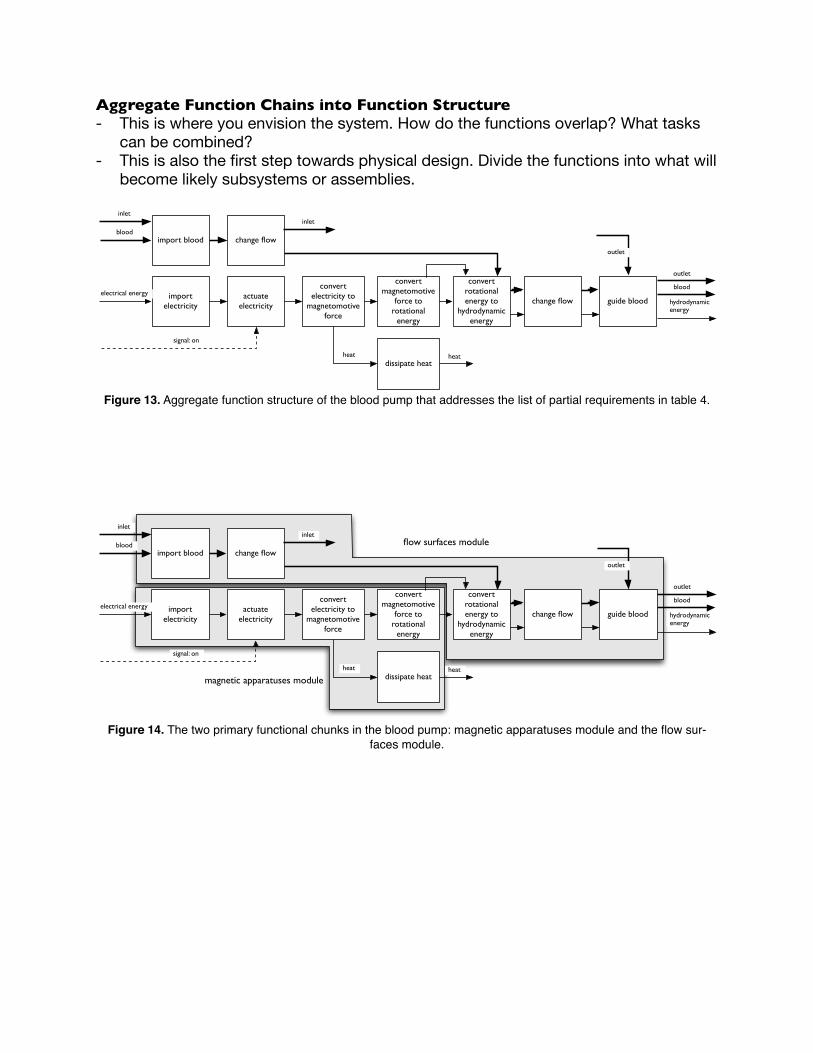
Aggregate Function Chains into Function Structure- This is where you envision the system. How do the functions overlap? What tasks
can be combined?- This is also the first step towards physical design. Divide the functions into what will
become likely subsystems or assemblies.
change flowimport blood
import electricity
actuate electricity
change flow
blood
electrical energy
signal: on
guide blood
convert electricity to
magnetomotive force
convert magnetomotive
force to rotational
energy
convert rotational energy to
hydrodynamic energy
heat
dissipate heatheat
outlet
hydrodynamicenergy
blood
outlet
inletinlet
Figure 13. Aggregate function structure of the blood pump that addresses the list of partial requirements in table 4.
change flowimport blood
import electricity
actuate electricity
change flow
blood
electrical energy
signal: on
guide blood
convert electricity to
magnetomotive force
convert magnetomotive
force to rotational
energy
convert rotational energy to
hydrodynamic energy
heat
dissipate heatheat
outlet
hydrodynamicenergy
blood
outlet
inletinlet
flow surfaces module
magnetic apparatuses module
Figure 14. The two primary functional chunks in the blood pump: magnetic apparatuses module and the flow sur-
faces module.

Explore Form with Morphological Chart- Brainstorm multiple physical solutions for each subfunction (a drawing is better than
a word)- Select a handful of combinations that are promising.- Performa a rough layout the components while focusing on major geometric con-
straints and interfaces.- Add sufficient detail to make an informed decision.
Table 5. A morphological chart of potential solutions for suspension and motor func-tions.
subfunction solution 1 solution 2 solution 3
suspension
motor
permanent magnets Lorentz bearing Maxwell bearing
brushless DC motorhybrid brushless DC motor and axial sus-
pension
Figure 16. A rough layout of high-level modules.
inletoutlet
flow
st
raig
hte
ner
flow
st
raig
hte
ner
rotorbla
de
statormotorstator
motorrotor
Lorentzstator
Lorentz rotor
PM radial
PM radial
c c
Figure 17. A rough layout of low-level components
inlet outlet
rotor
stationary components
magnetic apparatuses
magnetic apparatuses
c c

Lab - Chip Collator
Objectives
Complete a new design activity with a focus on identifying what this device must do (function) then how it will perform (form).
Complete an assessment of your design skills in preparation for the remainder of the semes-ter.
Agenda
Read and discuss the chip collator rules. Get pen ready. (15 min)
Design and fabricate chip collator machines. (this week and next)
Complete reporting activity. (45 min)
Record everything in this lab. You may need it for your reporting.
Chip collator requirements
The mechanism must take 5 poker chips from one stack, 5 poker chips from second stack, and alternate them in a final stack. (For example: If one stack starts out with blue chips and the other stack starts out with red chips, then the final stack will have alternating red, blue, red, blue chips.)
Each chip mush start face up and end face down.
The chips must begin in vertical stacks (parallel with the floor).
The chips must finish in a vertical stack without part of the mechanism touching the top chip in the stack.
The finishing stack must be no more than 4” vertically lower than the bottom of the starting stacks.
The chips may only be removed from the top of the starting stacks.
The chips must begin and end in vertical stacks.
Chip collator operation
The operator may not touch the chip.

Chip collator operation
The operator may move one control per pattern.
One operator move may not exceed a distance equal to the chip’s diameter.
MaterialsThe collator may be constructed from cardboard, hot glue, tape, paper, straws, tooth-picks, and paperclips.
Note on ReportingBe creative with the presentations! Use drawings, text, and dialog to make a compelling presentation. You can even make pseudo-slides, !animations", etc. Look at some exam-ples on Livescribe for inspiration.
Provide a link to all entries (team and individual) from your team website. The links should be posted by Monday Oct 27 at 12:30 PM.
Team ReportingCreate one entry as a team per question below. For each of these entries, use one of your team"s pens.1. Prepare 1-2 minute digital journal entry that gives an overview of your chip collator.2. Create a journal entry (5-7 min) in which you identify the functions that were needed
to make the chip collator operate. Then indicate when during the process the func-tion was identified and a when the physical solution that accomplishes that function was identified. Reference your teammate"s journal entries.
3. Compare your solution to the class"s collection of chip machines. Which solutions (in terms of function form) did you explicitly or coincidentally reuse? What changes did you make to adapt/integrate the solution? [example: We reused team 4!s flip mechanism from the chip flipper. It looked like X. We adapted it to look like Y in order to make it fit here.] (4-5 min)
Individual ReportingCreate one entry as an individual per question below. For each of these entries, use your own pen.1. Prepare a short description (3-5 minutes) of the design process including important
steps and motivation for following a process.2. Describe two strengths and weaknesses of your application or understanding of the
conceptual design process. Be sure to include the value of the strength and a plan for improving upon the weakness.
ScoringThe lab will be scored based on the effectiveness of your meta-cognition and the quality of your solution.

APPENDIX B
Rubric for documentation of the conceptual design process
This rubric focusses on the student!s success on documenting the conceptual design process. The conceptual design
process is generally considered to begin with the creation of a user needs document and ends with the selection of a
single design concept. A conceptual design typically has less detail than is required for manufacturing but sufficient
detail to make informed engineering decisions.
Low Med High
Identification of overall func-tional require-
ment
Exploration of subfunction
solutions
Exploration of alternate form
solutions
Select subsys-tem design so-
lution
Composition of product ar-
chitecture
Basic input and output flows are
not identified. No graphical
representation of information.
Misidentified or missing state-
ment of product function.
Minor input and output flows are
missing or misidentified. State-
ment of product function is pre-
sent, but potentially misleading
or awkward. A graphical repre-
sentation of the model is em-
ployed.
Black box, graphical model of
the product. Inputs and outputs
identified completely. Succinct
statement of product function
clearly identified.
No consideration of product
function was documented or
was captured in a non graphical
form.
Major product subfunctions
were identified and structured in
a visual/graphical representa-
tion. Connection between major
input/output flows and subfunc-
tions is established.
Extensive exploration of multi-
ple product subfunctions
through detailed graphical mod-
els. All product flows are cor-
rectly connected to functional
models.
Concept geometry is not repre-
sented or is captured intermit-
tently. A limited number of alter-
natives was explored. Estab-
lished function did not serve as
the basis for form.
Concept geometry is sketched
at a moderate level of detail,
including sufficient exploration
for the major product functions.
Use of function before form
process is mixed.
Concept geometry is sketched
in sufficient detail to make deci-
sions. Correspondence be-
tween function and form is
noted and logical. Functional
model served as a catalyst for
geometric models.
No clear logic is presented for
concept selection. Selected
concept may not be among the
represented design alternatives.
A comparison of alternatives is
modeled in a logical manner.
Some selection criteria is in-
complete with respect to the
specs.
Solution options are organized
in a structure that adds to deci-
sion maker!s understanding of
the solution and to facilitate
decision making process. Logic
behind the selection of solutions
is documented through a com-
parison to specs and other
solutions.
A complete vision of the product
function and geometry is not
produced.
A complete representation of
the geometry is present which
illustrates some interface prob-
lems. A composite functional
representation is produced, but
is incomplete or awkward.
Models of subfunction are com-
posed into a complete func-
tional representation. Geometry
of subsolutions are are outlined
in a schematic form and
sketched in a composite repre-
sentation. The product architec-
ture adds credibility to the solu-
tion as a whole.
J a y M c C o r m a c k! A D i g i t a l L o g b o o k f o r C o l l a b o r a t i o n a n d C o n c e p t u a l D e s i g n
1
Top Related