


Languages
Pages
Legal

6/0
Contents 0 6 - Pendant control stations and controllers
Pendant control stations with intuitive operationSelection guide . . . . . . . . . . . . . . . . . . . . . . . . . . . . . . . . . . . . . . . . . . . . . page 6/2
Double insulated, for control circuits
Complete stations “ready for use”, “Pistol grip”, type XAC A . . . . . . . . page 6/5 Complete stations “ready for use”, type XAC D . . . . . . . . . . . . . . . . . page 6/9
Double insulated, for power circuits (direct switching)
Complete stations “ready for use”, type XAC D . . . . . . . . . . . . . . . . .page 6/11
Double insulated, for control or power circuits
Empty enclosures, type XAC D . . . . . . . . . . . . . . . . . . . . . . . . . . . . . . . page 6/12Separate components and spare parts . . . . . . . . . . . . . . . . . . . . . . . . . page 6/12Variable composition stations, factory assembled . . . . . . . . . . . . page 6/17
Pendant control stationsSelection guide . . . . . . . . . . . . . . . . . . . . . . . . . . . . . . . . . . . . . . . . . . . . . page 6/2
Double insulated, type XAC A, for control circuits
Complete stations “ready for use” . . . . . . . . . . . . . . . . . . . . . . . . . . . page 6/19Empty enclosures . . . . . . . . . . . . . . . . . . . . . . . . . . . . . . . . . . . . . . . page 6/23Separate components and spare parts . . . . . . . . . . . . . . . . . . . . . . . page 6/24Variable composition stations, factory assembled . . . . . . . . . . . . page 6/33
Double insulated, type XAC B or metal, type XAC M (1)
Complete stations “ready for use”, type XAC B, for control circuits . . page 6/35Complete stations “ready for use”, type XAC B, for power circuits . . . page 6/37Empty enclosures, type XAC B, for control or power circuits . . . . . . . page 6/39Empty enclosures, type XAC B or XAC M, for control circuits . . . . . . . page 6/41Separate components and spare parts . . . . . . . . . . . . . . . . . . . . . . . page 6/42Variable composition stations, factory assembled . . . . . . . . . . . . . . . page 6/59
Double insulated, type XAC F, for control circuits (1)
Empty enclosures . . . . . . . . . . . . . . . . . . . . . . . . . . . . . . . . . . . . . . . page 6/61Variable composition stations, factory assembled . . . . . . . . . . . . . . . page 6/65
(1) XAC M and XAC F: products for maintenance purposes only.
b
v
v
b
v
b
v
v
v
b
v
v
v
v
b
v
v
v
v
v
v
b
v
v
Contents 0
6/0
6
6/1
ControllersSelection guide . . . . . . . . . . . . . . . . . . . . . . . . . . . . . . . . . . . . . . . . . . . . . . . . . 6/66
Controllers for “light hoisting” applications, type XKB
Controllers XKB A with predefi ned, non modifi able schemes, factory assembled . . . . . . . . . . . . . . . . . . . . . . . . . . . . . . . . . . . . . . . page 6/72Controllers XKB E with variable composition schemes,factory assembled . . . . . . . . . . . . . . . . . . . . . . . . . . . . . . . . . . . . . . . page 6/72Separate components . . . . . . . . . . . . . . . . . . . . . . . . . . . . . . . . . . . . page 6/75
Controllers for “medium hoisting” applications, type XKD F
Controllers with variable composition schemes, factory assembled . . . . . . . . . . . . . . . . . . . . . . . . . . . . . . . . . . . . . . . page 6/78Separate components . . . . . . . . . . . . . . . . . . . . . . . . . . . . . . . . . . . . page 6/83
Controllers for “heavy hoisting” applications, type XKM
Controllers XKM A and XKM B with variable composition schemes, factory assembled . . . . . . . . . . . . . . . . . . . . . . . . . . . . . . . . . . . . . . . page 6/86Controllers XKM C with variable composition schemes, factory assembled . . . . . . . . . . . . . . . . . . . . . . . . . . . . . . . . . . . . . . . page 6/93Separate components . . . . . . . . . . . . . . . . . . . . . . . . . . . . . . . . . . . . page 6/95
Potentiometers for controllers
For standard applications, type XKZ A . . . . . . . . . . . . . . . . . . . . . . . page 6/100For applications requiring an extended “neutral zone”, types XKB Z and XKD Z . . . . . . . . . . . . . . . . . . . . . . . . . . . . . . . . . page 6/101
b
v
v
v
b
v
v
b
v
v
v
b
v
v
6
1
2
3
4
5
6
7
8
9
10
1
2
3
4
5
6
7
8
9
10
1
2
3
4
5
6
7
8
9
10
6/2
Pendant control stations 6 Complete stations “ready for use” and variable composition stations
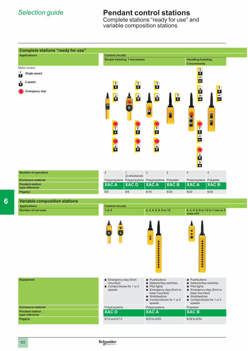
Complete stations “ready for use”Applications Control circuits
Simple hoisting: 1 movement Handling-hoisting: 2 movements
Motor control
Number of operators 2 1 (2-directional)
2 2 4 4
Enclosure material Polypropylene Polypropylene Polypropylene Polyester Polypropylene PolyesterPendant station type reference
XAC A XAC D XAC A XAC B XAC A XAC BPage(s) 6/5 6/9 6/19 6/35 6/20 6/35
Variable composition stationsApplications Control circuitsNumber of cut-outs 1 or 2 2, 3, 4, 5, 6, 8 or 12 2, 3, 4, 6, 8 or 12 in 1 row or 2
rows of 6
Equipment Emergency stop (front mounted) Contact blocks for 1 or 2 speeds
b
b
PushbuttonsSelector/key switchesPilot lightsEmergency stop (front or base mounted)WobblesticksContact blocks for 1 or 2 speeds
bbbb
bb
PushbuttonsSelector/key switchesPilot lightsEmergency stop (front or base mounted)WobblesticksContact blocks for 1 or 2 speeds
bbbb
bb
Enclosure material Polypropylene Polypropylene PolyesterPendant station type reference
XAC D XAC A XAC BPage(s) 6/12 and 6/13 6/23 to 6/29 6/39 to 6/54
Single-speed
2-speed
Emergency stop
Single-speed
2-speed
Emergency stop
Selection guide 6
1
2
3
4
5
6
7
8
9
10
6/3
6
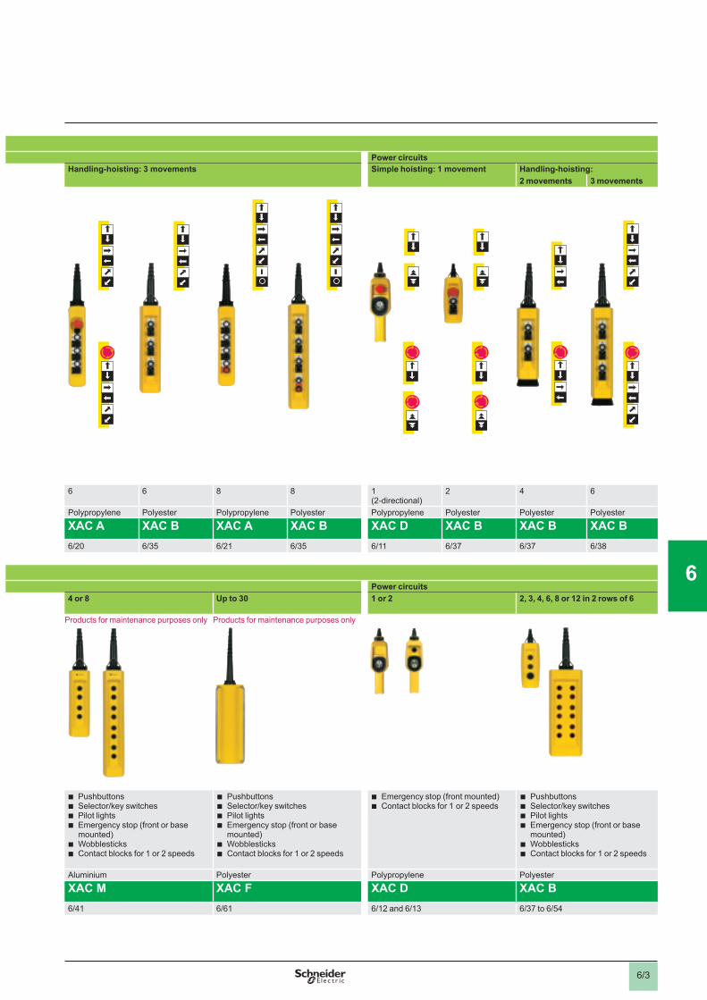
Power circuitsHandling-hoisting: 3 movements Simple hoisting: 1 movement Handling-hoisting:
2 movements 3 movements
6 6 8 8 1 (2-directional)
2 4 6
Polypropylene Polyester Polypropylene Polyester Polypropylene Polyester Polyester Polyester
XAC A XAC B XAC A XAC B XAC D XAC B XAC B XAC B 6/20 6/35 6/21 6/35 6/11 6/37 6/37 6/38
Power circuits4 or 8 Up to 30 1 or 2 2, 3, 4, 6, 8 or 12 in 2 rows of 6
Products for maintenance purposes only Products for maintenance purposes only
PushbuttonsSelector/key switchesPilot lightsEmergency stop (front or base mounted)WobblesticksContact blocks for 1 or 2 speeds
bbbb
bb
PushbuttonsSelector/key switchesPilot lightsEmergency stop (front or base mounted)WobblesticksContact blocks for 1 or 2 speeds
bbbb
bb
Emergency stop (front mounted) Contact blocks for 1 or 2 speeds
bb
PushbuttonsSelector/key switchesPilot lightsEmergency stop (front or base mounted)WobblesticksContact blocks for 1 or 2 speeds
bbbb
bb
Aluminium Polyester Polypropylene Polyester
XAC M XAC F XAC D XAC B 6/41 6/61 6/12 and 6/13 6/37 to 6/54
6
1
2
3
4
5
6
7
8
9
10
6/4
Current in A
Characteristics 6
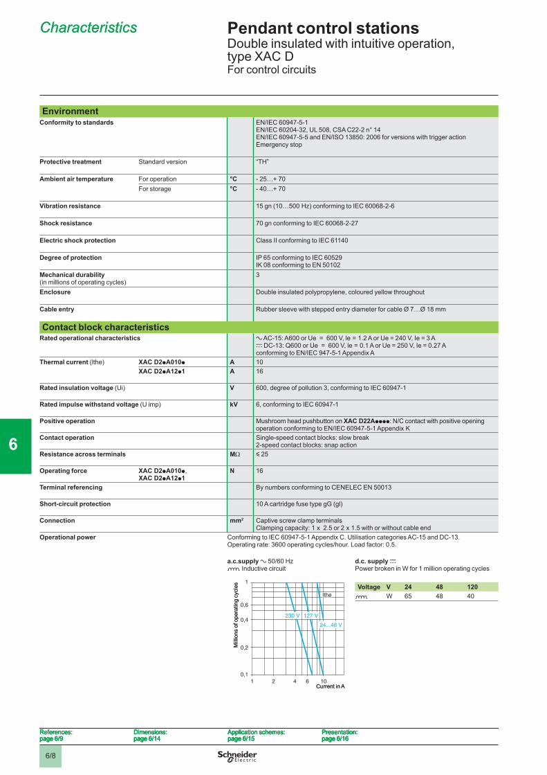
EnvironmentConformity to standards EN/IEC 60947-5-1
EN/IEC 60204-32, UL 508, CSA C22-2 n° 14EN/IEC 60947-5-5 and EN/ISO 13850: 2006 for versions with trigger action Emergency stop
Product certifi cations UL type 4X A600-Q600, CSA type 4 A600-Q600
Protective treatment Standard version “TH”
Ambient air temperature For operation °C - 25…+ 70For storage °C - 40…+ 70
Vibration resistance 15 gn (10…500 Hz) conforming to IEC 60068-2-6
Shock resistance 100 gn conforming to IEC 60068-2-27
Electric shock protection Class II conforming to IEC 61140
Degree of protection IP 65 conforming to IEC 60529 IK 08 conforming to EN 50102
Mechanical durability(in millions of operating cycles)
1
Enclosure Double insulated polypropylene, coloured yellow throughout
Cable entry Rubber sleeve with stepped entry diameter for cable Ø 7…Ø 15 mm
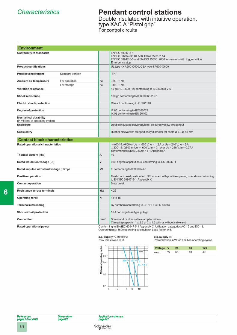
Contact block characteristicsRated operational characteristics a AC-15: A600 or Ue = 600 V, le = 1.2 A or Ue = 240 V, Ie = 3 A
c DC-13: Q600 or Ue = 600 V, le = 0.1 A or Ue = 250 V, Ie = 0.27 Aconforming to EN/IEC 60947-5-1 Appendix A
Thermal current (lthe) A 10
Rated insulation voltage (Ui) V 600, degree of pollution 3, conforming to IEC 60947-1
Rated impulse withstand voltage (U imp) kV 6, conforming to IEC 60947-1
Positive operation Mushroom head pushbutton: N/C contact with positive opening operation conforming to EN/IEC 60947-5-1 Appendix K
Contact operation Slow break
Resistance across terminals MΩ y 25
Operating force N 13 to 15
Terminal referencing By numbers conforming to CENELEC EN 50013
Short-circuit protection 10 A cartridge fuse type gG (gl)
Connection mm2 Screw and captive cable clamp terminals.Clamping capacity: 1 x 2.5 or 2 x 1.5 with or without cable end
Rated operational power Conforming to EN/IEC 60947-5-1 Appendix C. Utilisation categories AC-15 and DC-13.Operating rate: 3600 operating cycles/hour. Load factor: 0.5.
a.c. supply a 50/60 Hzo Inductive circuit
d.c. supply c Power broken in W for 1 million operating cycles
Voltage V 24 48 120o W 65 48 40
1 2 4 6 10
0,1
0,2
0,4
0,6
1
230 V 127 V
24...48 V
Ithe
Mill
ions
of o
pera
ting
cycl
es
1 2 4 6 10
0,1
0,2
0,4
0,6
1
230 V 127 V
24...48 V
Ithe
Mill
ions
of o
pera
ting
cycl
es
References:pages 6/5 and 6/6
Dimensions:page 6/7
Application schemes:page 6/7
References:pages 6/5 and 6/6
Dimensions:page 6/7
Application schemes:page 6/7
References:pages 6/5 and 6/6
Dimensions:page 6/7
Application schemes:page 6/7
References:pages 6/5 and 6/6
Dimensions:page 6/7
Application schemes:page 6/7
Pendant control stations 6 Double insulated with intuitive operation, type XAC A “Pistol grip”For control circuits
1
2
3
4
5
6
7
8
9
10
6/5
References 6
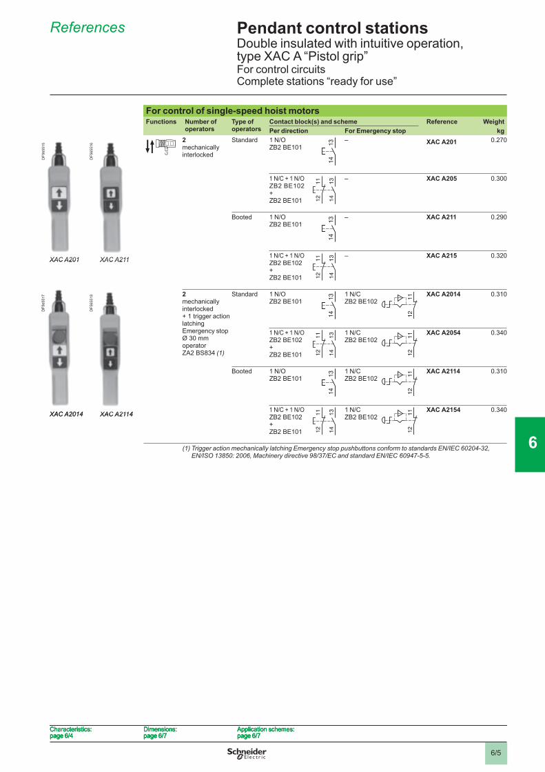
For control of single-speed hoist motors Functions Number of
operatorsType of operators
Contact block(s) and scheme Reference WeightPer direction For Emergency stop kg
2 mechanically interlocked
Standard 1 N/O ZB2 BE101
– XAC A201 0.270
1 N/C + 1 N/OZB2 BE102+ ZB2 BE101
– XAC A205 0.300
Booted 1 N/O ZB2 BE101
– XAC A211 0.290
1 N/C + 1 N/OZB2 BE102+ ZB2 BE101
– XAC A215 0.320
2 mechanically interlocked + 1 trigger action latching Emergency stop Ø 30 mm operator ZA2 BS834 (1)
Standard 1 N/O ZB2 BE101
1 N/C ZB2 BE102
XAC A2014 0.310
1 N/C + 1 N/OZB2 BE102+ ZB2 BE101
1 N/C ZB2 BE102
XAC A2054 0.340
Booted 1 N/O ZB2 BE101
1 N/C ZB2 BE102
XAC A2114 0.310
1 N/C + 1 N/OZB2 BE102+ ZB2 BE101
1 N/C ZB2 BE102
XAC A2154 0.340
(1) Trigger action mechanically latching Emergency stop pushbuttons conform to standards EN/IEC 60204-32, EN/ISO 13850: 2006, Machinery directive 98/37/EC and standard EN/IEC 60947-5-5.
13
14
13
14
XAC A201
DF5
6551
5
XAC A211
DF5
6551
6
XAC A201
DF5
6551
5
XAC A211
DF5
6551
6
13
14
11
12
13
14
11
12
13
14
13
14
13
14
11
12
13
14
11
12
XAC A2014
DF5
6551
7
XAC A2114
DF5
6551
8
XAC A2014
DF5
6551
7
XAC A2114
DF5
6551
8
13
14
13
14
11
12
11
12
13
14
11
12
13
14
11
12
11
12
11
12
13
14
13
14
11
12
11
12
13
14
11
12
13
14
11
12
11
12
11
12
Characteristics:page 6/4
Dimensions:page 6/7
Application schemes:page 6/7
Characteristics:page 6/4
Dimensions:page 6/7
Application schemes:page 6/7
Characteristics:page 6/4
Dimensions:page 6/7
Application schemes:page 6/7
Characteristics:page 6/4
Dimensions:page 6/7
Application schemes:page 6/7
Pendant control stations 6 Double insulated with intuitive operation, type XAC A “Pistol grip”For control circuitsComplete stations “ready for use”
1
2
3
4
5
6
7
8
9
10
6/6
References 6
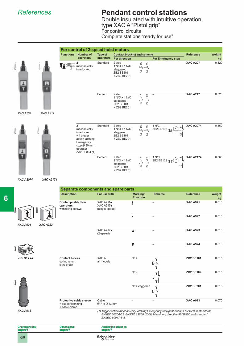
For control of 2-speed hoist motors Functions Number of
operatorsType of operators
Contact block(s) and scheme Reference WeightPer direction For Emergency stop kg
2 mechanically interlocked
Standard 2 step1 N/O + 1 N/O staggered ZB2 BE101 + ZB2 BE201
– XAC A207 0.320
Booted 2 step1 N/O + 1 N/O staggered ZB2 BE101 + ZB2 BE201
– XAC A217 0.320
2 mechanically interlocked + 1 trigger action latching Emergency stop Ø 30 mm operator ZA2 BS834 (1)
Standard 2 step1 N/O + 1 N/O staggered ZB2 BE101 + ZB2 BE201
1 N/CZB2 BE102
XAC A2074 0.360
Booted 2 step1 N/O + 1 N/O staggered ZB2 BE101 + ZB2 BE201
1 N/CZB2 BE102
XAC A2174 0.360
Separate components and spare partsDescription For use with Marking/
FunctionScheme Reference Weight
kgBooted pushbutton operators with fi xing screws
XAC A211p XAC A215p (single-speed)
– XAC A921 0.010
– XAC A922 0.010
XAC A217p (2-speed)
– XAC A923 0.010
– XAC A924 0.010
Contact blocks spring return,slow break
XAC Aall models
N/O ZB2 BE101 0.015
N/C ZB2 BE102 0.015
N/O staggered ZB2 BE201 0.015
Protective cable sleeve + suspension ring + cable clamp
Cable Ø 7 to Ø 13 mm
– – XAC A913 0.070
(1) Trigger action mechanically latching Emergency stop pushbuttons conform to standards EN/IEC 60204-32, EN/ISO 13850: 2006, Machinery directive 98/37/EC and standard EN/IEC 60947-5-5.
13
14
23
24
13
14
23
24
XAC A207
DF5
6552
0
XAC A217
DF5
6551
9
XAC A207
DF5
6552
0
XAC A217
DF5
6551
9
13
14
23
24
13
14
23
24
XAC A2074
DF5
6552
1
XAC A2174
DF5
6552
2
XAC A2074
DF5
6552
1
XAC A2174
DF5
6552
2 13
14
23
24
13
14
23
24
11
12
11
12
13
14
23
24
13
14
23
24
11
12
11
12
XAC A921
8039
98
XAC A921
8039
98
XAC A923
8039
90
XAC A923
8039
90
ZB2 BEppp
5306
67
ZB2 BEppp
5306
67
●2
●1
●2
●1
XAC A913
5306
68
XAC A913
5306
68
Characteristics:page 6/4
Dimensions:page 6/7
Application schemes:page 6/7
Characteristics:page 6/4
Dimensions:page 6/7
Application schemes:page 6/7
Characteristics:page 6/4
Dimensions:page 6/7
Application schemes:page 6/7
Characteristics:page 6/4
Dimensions:page 6/7
Application schemes:page 6/7
Pendant control stations 6 Double insulated with intuitive operation, type XAC A “Pistol grip”For control circuitsComplete stations “ready for use”
1
2
3
4
5
6
7
8
9
10
6/7
Dimensions, application schemes 6
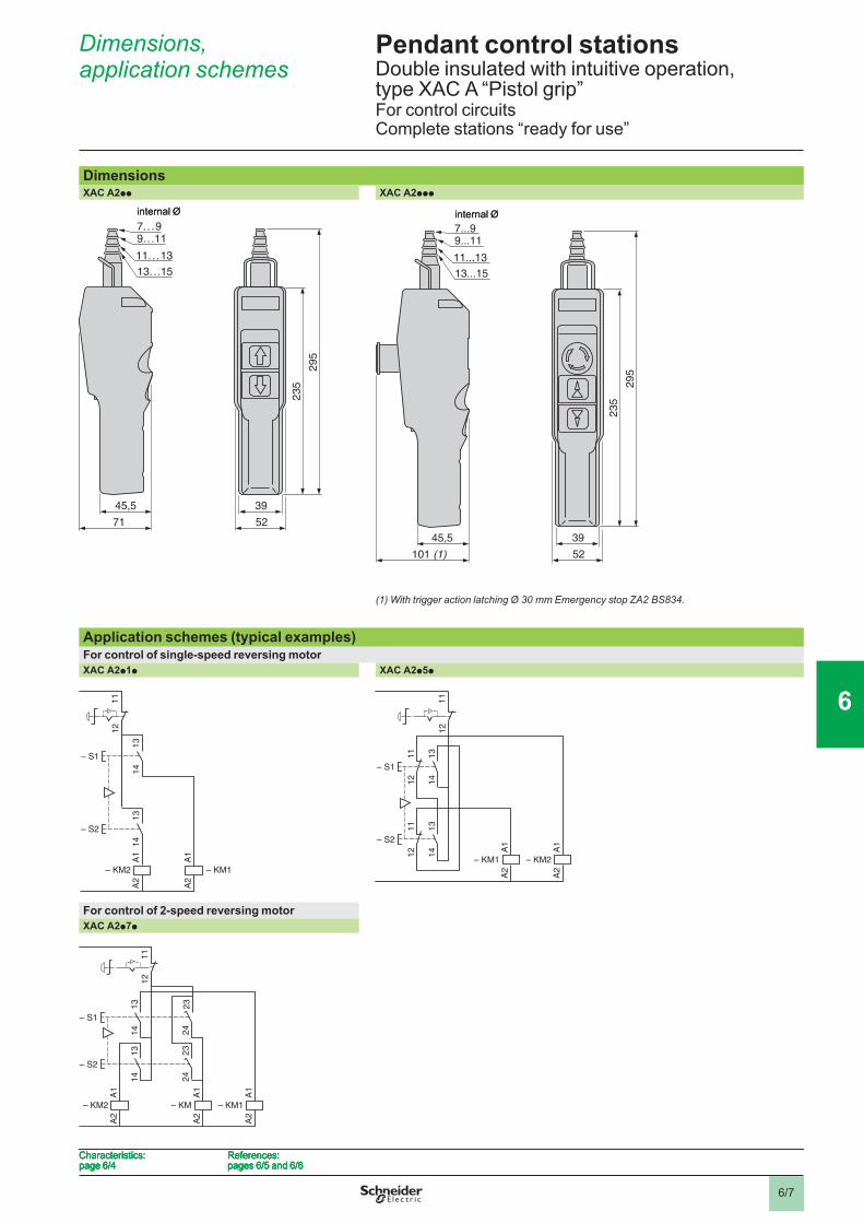
DimensionsXAC A2pp XAC A2ppp
(1) With trigger action latching Ø 30 mm Emergency stop ZA2 BS834.
Application schemes (typical examples)For control of single-speed reversing motorXAC A2p1p XAC A2p5p
For control of 2-speed reversing motorXAC A2p7p
11.. .13
71
45,5
7.. .99. . .11
13.. .15
39
235
295
52
internal Ø
11.. .13
71
45,5
7.. .99. . .11
13.. .15
39
235
295
52
internal Ø
39
235
295
52101 (1)
45,5
11...13
7...99...11
13...15
internal Ø
39
235
295
52101 (1)
45,5
11...13
7...99...11
13...15
internal Ø
13
14
13
14
A1
A2
– KM2
– S1
A1
A2
– KM1
– S2
11
12
13
14
13
14
A1
A2
– KM2
– S1
A1
A2
– KM1
– S2
11
12
13
14
11
12
13
14
11
12 A
1A
2
– KM1
– S1
A1
A2
– KM2
– S2
11
12
13
14
11
12
13
14
11
12 A
1A
2
– KM1
– S1
A1
A2
– KM2
– S2
11
12
24
23
24
13
23
14
13
14
A1
A2
– KM1
A1
A2
– KM
– S1
A1
A2
– KM2
– S2
11
12
24
23
24
13
23
14
13
14
A1
A2
– KM1
A1
A2
– KM
– S1
A1
A2
– KM2
– S2
11
12
Characteristics:page 6/4
References:pages 6/5 and 6/6
Characteristics:page 6/4
References:pages 6/5 and 6/6
Characteristics:page 6/4
References:pages 6/5 and 6/6
Characteristics:page 6/4
References:pages 6/5 and 6/6
Pendant control stations 6 Double insulated with intuitive operation, type XAC A “Pistol grip”For control circuitsComplete stations “ready for use”
1
2
3
4
5
6
7
8
9
10
6/8
EnvironmentConformity to standards EN/IEC 60947-5-1
EN/IEC 60204-32, UL 508, CSA C22-2 n° 14EN/IEC 60947-5-5 and EN/ISO 13850: 2006 for versions with trigger action Emergency stop
Protective treatment Standard version “TH”
Ambient air temperature For operation °C - 25…+ 70For storage °C - 40…+ 70
Vibration resistance 15 gn (10…500 Hz) conforming to IEC 60068-2-6
Shock resistance 70 gn conforming to IEC 60068-2-27
Electric shock protection Class II conforming to IEC 61140
Degree of protection IP 65 conforming to IEC 60529IK 08 conforming to EN 50102
Mechanical durability(in millions of operating cycles)
3
Enclosure Double insulated polypropylene, coloured yellow throughout
Cable entry Rubber sleeve with stepped entry diameter for cable Ø 7…Ø 18 mm
Contact block characteristicsRated operational characteristics a AC-15: A600 or Ue = 600 V, le = 1.2 A or Ue = 240 V, Ie = 3 A
c DC-13: Q600 or Ue = 600 V, le = 0.1 A or Ue = 250 V, Ie = 0.27 Aconforming to EN/IEC 947-5-1 Appendix A
Thermal current (lthe) XAC D2pA010p A 10XAC D2pA12p1 A 16
Rated insulation voltage (Ui) V 600, degree of pollution 3, conforming to IEC 60947-1
Rated impulse withstand voltage (U imp) kV 6, conforming to IEC 60947-1
Positive operation Mushroom head pushbutton on XAC D22Apppp: N/C contact with positive opening operation conforming to EN/IEC 60947-5-1 Appendix K
Contact operation Single-speed contact blocks: slow break2-speed contact blocks: snap action
Resistance across terminals MΩ y 25
Operating force XAC D2pA010p, XAC D2pA12p1
N 16
Terminal referencing By numbers conforming to CENELEC EN 50013
Short-circuit protection 10 A cartridge fuse type gG (gl)
Connection mm2 Captive screw clamp terminalsClamping capacity: 1 x 2.5 or 2 x 1.5 with or without cable end
Operational power Conforming to IEC 60947-5-1 Appendix C. Utilisation categories AC-15 and DC-13.Operating rate: 3600 operating cycles/hour. Load factor: 0.5.
a.c.supply a 50/60 Hzo Inductive circuit
d.c. supply c Power broken in W for 1 million operating cycles
Voltage V 24 48 120o W 65 48 40
1 2 4 6 10
0,1
0,2
0,4
0,6
1
230 V 127 V
24...48 V
Ithe
Mill
ions
of o
pera
ting
cycl
es
Current in A1 2 4 6 10
0,1
0,2
0,4
0,6
1
230 V 127 V
24...48 V
Ithe
Mill
ions
of o
pera
ting
cycl
es
Current in A
References:page 6/9
Dimensions:page 6/14
Application schemes:page 6/15
Presentation:page 6/16
References:page 6/9
Dimensions:page 6/14
Application schemes:page 6/15
Presentation:page 6/16
References:page 6/9
Dimensions:page 6/14
Application schemes:page 6/15
Presentation:page 6/16
References:page 6/9
Dimensions:page 6/14
Application schemes:page 6/15
Presentation:page 6/16
Pendant control stations 6 Double insulated with intuitive operation, type XAC DFor control circuits
Characteristics 6 Characteristics 6
1
2
3
4
5
6
7
8
9
10
6/9
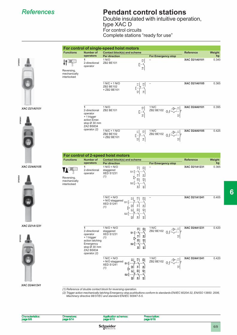
For control of single-speed hoist motorsFunctions Number of
operatorsContact block(s) and scheme Reference Weight
kgPer direction For Emergency stop
Reversing, mechanically interlocked
1 2-directional operator
1 N/O ZB2 BE101
– XAC D21A0101 0.340
1 N/C + 1 N/O ZB2 BE102+ ZB2 BE101
– XAC D21A0105 0.365
1 2-directional operator+ 1 trigger action Emer. stop Ø 30 mm ZA2 BS834 operator (2)
1 N/OZB2 BE101
1 N/C ZB2 BE102
XAC D24A0101 0.395
1 N/C + 1 N/O ZB2 BE102+ ZB2 BE101
1 N/C ZB2 BE102
XAC D24A0105 0.425
For control of 2-speed hoist motorsFunctions Number of
operatorsContact block(s) and scheme Reference Weight
kgPer direction For Emergency stop
Reversing, mechanically interlocked
1 2-directional operator
1 N/O + N/O staggered XED S1231 (1)
– XAC D21A1231 0.365
1 N/C + N/O + N/O staggered XED S1241 (1)
– XAC D21A1241 0.405
1 2-directional operator+ 1 trigger action latching Emergency stop Ø 30 mm ZA2 BS834 operator (2)
1 N/O + N/O staggered XED S1231 (1)
1 N/C ZB2 BE102
XAC D24A1231 0.420
1 N/C + N/O + N/O staggered XED S1241 (1)
1 N/C ZB2 BE102
XAC D24A1241 0.420
(1) Reference of double contact block for reversing operation.(2) Trigger action mechanically latching Emergency stop pushbuttons conform to standards EN/IEC 60204-32, EN/ISO 13850: 2006,
Machinery directive 98/37/EC and standard EN/IEC 60947-5-5.
13
14
13
14
XAC D21A0101
DF5
6550
3
XAC D21A0101
DF5
6550
3
13
14
11
12
13
14
11
12
XAC D24A0105
DF5
6550
1
XAC D24A0105
DF5
6550
1
13
14
13
14
11
12
11
12
13
14
11
12
13
14
11
12
11
12
11
12
23
24
13
14
43
44
33
34
S1
S2
23
24
13
14
43
44
33
34
S1
S2
XAC D21A1231
DF5
6550
4
XAC D21A1231
DF5
6550
4
23
24
52
51
13
14
43
44
62
61
33
34
S1
S2
23
24
52
51
13
14
43
44
62
61
33
34
S1
S2
XAC D24A1241
DF5
6550
2
XAC D24A1241
DF5
6550
2
11
12
11
12
23
24
13
14
43
44
33
34
S1
S2
23
24
13
14
43
44
33
34
S1
S2
11
12
11
12
23
24
52
51
13
14
43
44
62
61
33
34
S1
S2
23
24
52
51
13
14
43
44
62
61
33
34
S1
S2
Characteristics:page 6/8
Dimensions:page 6/14
Application schemes:page 6/15
Presentation:page 6/16
Characteristics:page 6/8
Dimensions:page 6/14
Application schemes:page 6/15
Presentation:page 6/16
Characteristics:page 6/8
Dimensions:page 6/14
Application schemes:page 6/15
Presentation:page 6/16
Characteristics:page 6/8
Dimensions:page 6/14
Application schemes:page 6/15
Presentation:page 6/16
Pendant control stations 6 Double insulated with intuitive operation, type XAC DFor control circuitsComplete stations “ready for use”
References 6 References 6
1
2
3
4
5
6
7
8
9
10
6/10
Characteristics 6
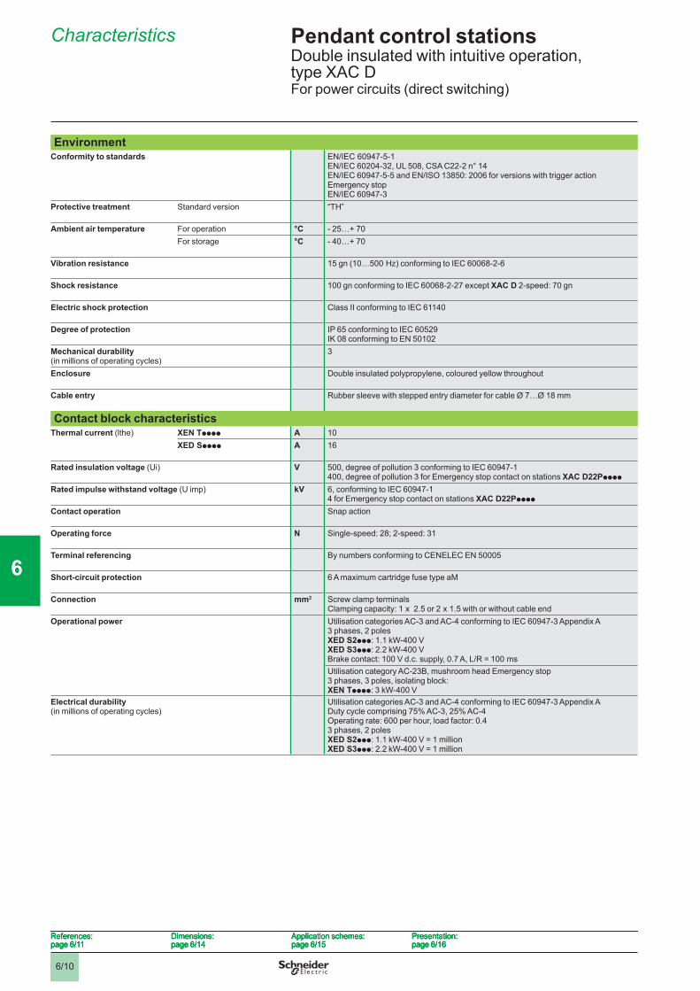
EnvironmentConformity to standards EN/IEC 60947-5-1
EN/IEC 60204-32, UL 508, CSA C22-2 n° 14EN/IEC 60947-5-5 and EN/ISO 13850: 2006 for versions with trigger action Emergency stopEN/IEC 60947-3
Protective treatment Standard version “TH”
Ambient air temperature For operation °C - 25…+ 70For storage °C - 40…+ 70
Vibration resistance 15 gn (10…500 Hz) conforming to IEC 60068-2-6
Shock resistance 100 gn conforming to IEC 60068-2-27 except XAC D 2-speed: 70 gn
Electric shock protection Class II conforming to IEC 61140
Degree of protection IP 65 conforming to IEC 60529IK 08 conforming to EN 50102
Mechanical durability(in millions of operating cycles)
3
Enclosure Double insulated polypropylene, coloured yellow throughout
Cable entry Rubber sleeve with stepped entry diameter for cable Ø 7…Ø 18 mm
Contact block characteristicsThermal current (lthe) XEN Tpppp A 10
XED Spppp A 16
Rated insulation voltage (Ui) V 500, degree of pollution 3 conforming to IEC 60947-1400, degree of pollution 3 for Emergency stop contact on stations XAC D22Ppppp
Rated impulse withstand voltage (U imp) kV 6, conforming to IEC 60947-14 for Emergency stop contact on stations XAC D22Ppppp
Contact operation Snap action
Operating force N Single-speed: 28; 2-speed: 31
Terminal referencing By numbers conforming to CENELEC EN 50005
Short-circuit protection 6 A maximum cartridge fuse type aM
Connection mm2 Screw clamp terminalsClamping capacity: 1 x 2.5 or 2 x 1.5 with or without cable end
Operational power Utilisation categories AC-3 and AC-4 conforming to IEC 60947-3 Appendix A3 phases, 2 polesXED S2ppp: 1.1 kW-400 VXED S3ppp: 2.2 kW-400 VBrake contact: 100 V d.c. supply, 0.7 A, L/R = 100 msUtilisation category AC-23B, mushroom head Emergency stop3 phases, 3 poles, isolating block:XEN Tpppp: 3 kW-400 V
Electrical durability(in millions of operating cycles)
Utilisation categories AC-3 and AC-4 conforming to IEC 60947-3 Appendix ADuty cycle comprising 75% AC-3, 25% AC-4Operating rate: 600 per hour, load factor: 0.43 phases, 2 polesXED S2ppp: 1.1 kW-400 V = 1 millionXED S3ppp: 2.2 kW-400 V = 1 million
References:page 6/11
Dimensions:page 6/14
Application schemes:page 6/15
Presentation:page 6/16
References:page 6/11
Dimensions:page 6/14
Application schemes:page 6/15
Presentation:page 6/16
References:page 6/11
Dimensions:page 6/14
Application schemes:page 6/15
Presentation:page 6/16
References:page 6/11
Dimensions:page 6/14
Application schemes:page 6/15
Presentation:page 6/16
Pendant control stations 6 Double insulated with intuitive operation, type XAC DFor power circuits (direct switching)
1
2
3
4
5
6
7
8
9
10
6/11
Pendant control stations 6 Double insulated with intuitive operation, type XAC DFor power circuits (direct switching)Complete stations “ready for use”
References 6
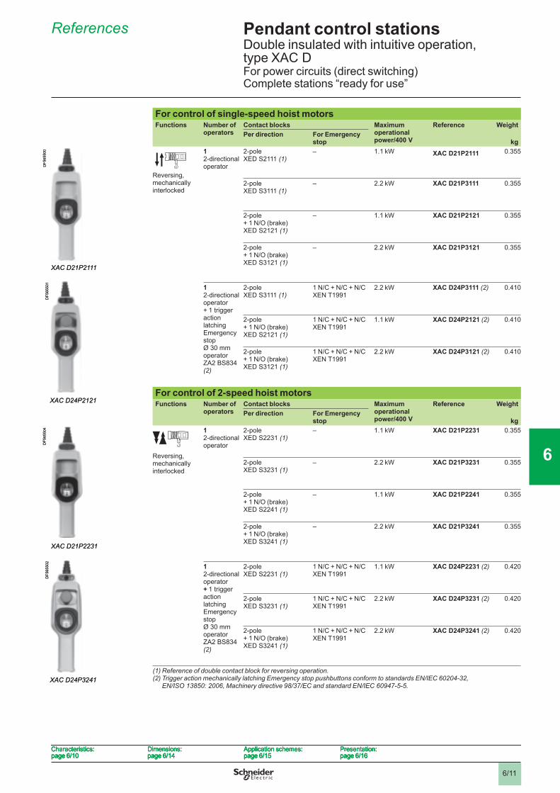
For control of single-speed hoist motors Functions Number of
operatorsContact blocks Maximum
operational power/400 V
Reference WeightPer direction For Emergency
stop kg
Reversing, mechanically interlocked
1 2-directional operator
2-pole XED S2111 (1)
– 1.1 kW XAC D21P2111 0.355
2-pole XED S3111 (1)
– 2.2 kW XAC D21P3111 0.355
2-pole+ 1 N/O (brake) XED S2121 (1)
– 1.1 kW XAC D21P2121 0.355
2-pole+ 1 N/O (brake) XED S3121 (1)
– 2.2 kW XAC D21P3121 0.355
1 2-directional operator+ 1 trigger action latching Emergency stop Ø 30 mm operator ZA2 BS834 (2)
2-pole XED S3111 (1)
1 N/C + N/C + N/CXEN T1991
2.2 kW XAC D24P3111 (2) 0.410
2-pole+ 1 N/O (brake)XED S2121 (1)
1 N/C + N/C + N/CXEN T1991
1.1 kW XAC D24P2121 (2) 0.410
2-pole+ 1 N/O (brake)XED S3121 (1)
1 N/C + N/C + N/CXEN T1991
2.2 kW XAC D24P3121 (2) 0.410
For control of 2-speed hoist motors Functions Number of
operatorsContact blocks Maximum
operational power/400 V
Reference WeightPer direction For Emergency
stop kg
Reversing, mechanically interlocked
1 2-directional operator
2-pole XED S2231 (1)
– 1.1 kW XAC D21P2231 0.355
2-pole XED S3231 (1)
– 2.2 kW XAC D21P3231 0.355
2-pole+ 1 N/O (brake) XED S2241 (1)
– 1.1 kW XAC D21P2241 0.355
2-pole+ 1 N/O (brake) XED S3241 (1)
– 2.2 kW XAC D21P3241 0.355
1 2-directional operator + 1 trigger action latching Emergency stop Ø 30 mm operator ZA2 BS834 (2)
2-poleXED S2231 (1)
1 N/C + N/C + N/CXEN T1991
1.1 kW XAC D24P2231 (2) 0.420
2-pole XED S3231 (1)
1 N/C + N/C + N/CXEN T1991
2.2 kW XAC D24P3231 (2) 0.420
2-pole+ 1 N/O (brake) XED S3241 (1)
1 N/C + N/C + N/CXEN T1991
2.2 kW XAC D24P3241 (2) 0.420
(1) Reference of double contact block for reversing operation.(2) Trigger action mechanically latching Emergency stop pushbuttons conform to standards EN/IEC 60204-32,
EN/ISO 13850: 2006, Machinery directive 98/37/EC and standard EN/IEC 60947-5-5.
XAC D21P2111
DF5
6550
0
XAC D21P2111
DF5
6550
0
XAC D24P2121
DF5
6550
1
XAC D24P2121
DF5
6550
1
XAC D21P2231
DF5
6550
4
XAC D21P2231
DF5
6550
4
XAC D24P3241
DF5
6550
2
XAC D24P3241
DF5
6550
2
Characteristics:page 6/10
Dimensions:page 6/14
Application schemes:page 6/15
Presentation:page 6/16
Characteristics:page 6/10
Dimensions:page 6/14
Application schemes:page 6/15
Presentation:page 6/16
Characteristics:page 6/10
Dimensions:page 6/14
Application schemes:page 6/15
Presentation:page 6/16
Characteristics:page 6/10
Dimensions:page 6/14
Application schemes:page 6/15
Presentation:page 6/16
1
2
3
4
5
6
7
8
9
10
6/12
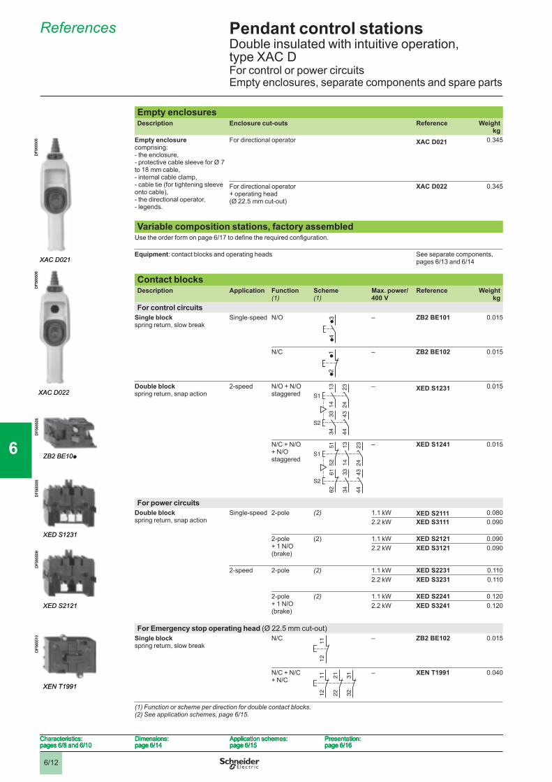
Pendant control stations 6 Double insulated with intuitive operation, type XAC DFor control or power circuitsEmpty enclosures, separate components and spare parts
References 6
Empty enclosuresDescription Enclosure cut-outs Reference Weight
kgEmpty enclosurecomprising:- the enclosure, - protective cable sleeve for Ø 7 to 18 mm cable, - internal cable clamp, - cable tie (for tightening sleeve onto cable), - the directional operator, - legends.
For directional operator XAC D021 0.345
For directional operator+ operating head(Ø 22.5 mm cut-out)
XAC D022 0.345
Variable composition stations, factory assembledUse the order form on page 6/17 to defi ne the required confi guration.
Equipment: contact blocks and operating heads See separate components,pages 6/13 and 6/14
Contact blocks Description Application Function
(1)Scheme(1)
Max. power/400 V
Reference Weightkg
For control circuitsSingle blockspring return, slow break
Single-speed N/O – ZB2 BE101 0.015
N/C – ZB2 BE102 0.015
Double blockspring return, snap action
2-speed N/O + N/O staggered
– XED S1231 0.015
N/C + N/O + N/O staggered
– XED S1241 0.015
For power circuitsDouble blockspring return, snap action
Single-speed 2-pole (2) 1.1 kW XED S2111 0.0802.2 kW XED S3111 0.090
2-pole + 1 N/O (brake)
(2) 1.1 kW XED S2121 0.0902.2 kW XED S3121 0.090
2-speed 2-pole (2) 1.1 kW XED S2231 0.1102.2 kW XED S3231 0.110
2-pole + 1 N/O (brake)
(2) 1.1 kW XED S2241 0.1202.2 kW XED S3241 0.120
For Emergency stop operating head (Ø 22.5 mm cut-out) Single blockspring return, slow break
N/C – ZB2 BE102 0.015
N/C + N/C + N/C
– XEN T1991 0.040
(1) Function or scheme per direction for double contact blocks.(2) See application schemes, page 6/15 .
XAC D021
DF5
6550
5
XAC D021
DF5
6550
5
XAC D022
DF5
6550
6
XAC D022
DF5
6550
6
●3
●4
●3
●4
ZB2 BE10p
DF5
6550
5
ZB2 BE10p
DF5
6550
5
●2
●1
●2
●1
23
24
13
14
43
44
33
34
S1
S2
23
24
13
14
43
44
33
34
S1
S2
XED S1231
DF5
6550
5
XED S1231
DF5
6550
5
23
24
52
51
13
14
43
44
62
61
33
34
S1
S2
23
24
52
51
13
14
43
44
62
61
33
34
S1
S2
XED S2121
DF5
6550
9
XED S2121
DF5
6550
9
11
12
11
12
11
12
21
22
31
32
11
12
21
22
31
32
XEN T1991
DF5
6551
0
XEN T1991
DF5
6551
0
Characteristics:pages 6/8 and 6/10
Dimensions:page 6/14
Application schemes:page 6/15
Presentation:page 6/16
Characteristics:pages 6/8 and 6/10
Dimensions:page 6/14
Application schemes:page 6/15
Presentation:page 6/16
Characteristics:pages 6/8 and 6/10
Dimensions:page 6/14
Application schemes:page 6/15
Presentation:page 6/16
Characteristics:pages 6/8 and 6/10
Dimensions:page 6/14
Application schemes:page 6/15
Presentation:page 6/16
1
2
3
4
5
6
7
8
9
10
6/13
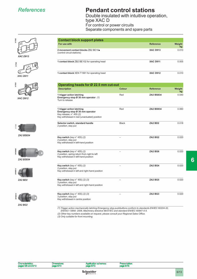
Pendant control stations 6 Double insulated with intuitive operation, type XAC DFor control or power circuitsSeparate components and spare parts
References 6
Contact block support plates For use with Reference Weight
kg2 movement contact blocks ZB2 BE10p(control circuit stations)
XAC D913 0.010
1 contact block ZB2 BE102 for operating head XAC D911 0.005
1 contact block XEN T1991 for operating head XAC D912 0.010
Operating heads for Ø 22.5 mm cut-out Description Colour Reference Weight
kg1 trigger action latching Emergency stop Ø 30 mm operator (1)Turn to release
Red ZA2 BS834 0.040
1 trigger action latching Emergency stop Ø 30 mm operator Key release, n° 455 (2)Key withdrawal in rest (unactuated) position
Red ZA2 BS934 0.060
Selector switch, standard handle 2 position, stay put
Black ZA2 BD2 0.018
Key switch (key n° 455) (2) 2 position, stay putKey withdrawal in left-hand position
– ZA2 BG2 0.020
Key switch (key n° 455) (2) 2 position, spring return from right to leftKey withdrawal in left-hand position
– ZA2 BG6 0.020
Key switch (key n° 455) (2) 2 position, stay putKey withdrawal in left and right-hand position
– ZA2 BG4 0.020
Key switch (key n° 455) (2) (3)3 position, stay putKey withdrawal in left and right-hand position
– ZA2 BG5 0.020
Key switch (key n° 455) (2) (3)3 position, stay putKey withdrawal in centre position
– ZA2 BG3 0.020
(1) Trigger action mechanically latching Emergency stop pushbuttons conform to standards EN/IEC 60204-32, EN/ISO 13850: 2006, Machinery directive 98/37/EC and standard EN/IEC 60947-5-5.
(2) Other key numbers available on request, please consult your Regional Sales Offi ce. (3) Only suitable for front mounting.
XAC D913
8175
05
XAC D911
8175
0381
7504
XAC D912
XAC D913
8175
05
XAC D911
8175
0381
7504
XAC D912
ZA2 BS834
8174
95
ZA2 BS834
8174
95
ZA2 BS934
DF5
3849
4
ZA2 BS934
DF5
3849
4
ZA2 BD2
DF5
6551
3
ZA2 BD2
DF5
6551
3
ZA2 BG2
DF5
6551
4
ZA2 BG2
DF5
6551
4
Characteristics:pages 6/8 and 6/10
Dimensions:page 6/14
Application schemes:page 6/15
Presentation:page 6/16
Characteristics:pages 6/8 and 6/10
Dimensions:page 6/14
Application schemes:page 6/15
Presentation:page 6/16
Characteristics:pages 6/8 and 6/10
Dimensions:page 6/14
Application schemes:page 6/15
Presentation:page 6/16
Characteristics:pages 6/8 and 6/10
Dimensions:page 6/14
Application schemes:page 6/15
Presentation:page 6/16
1
2
3
4
5
6
7
8
9
10
6/14
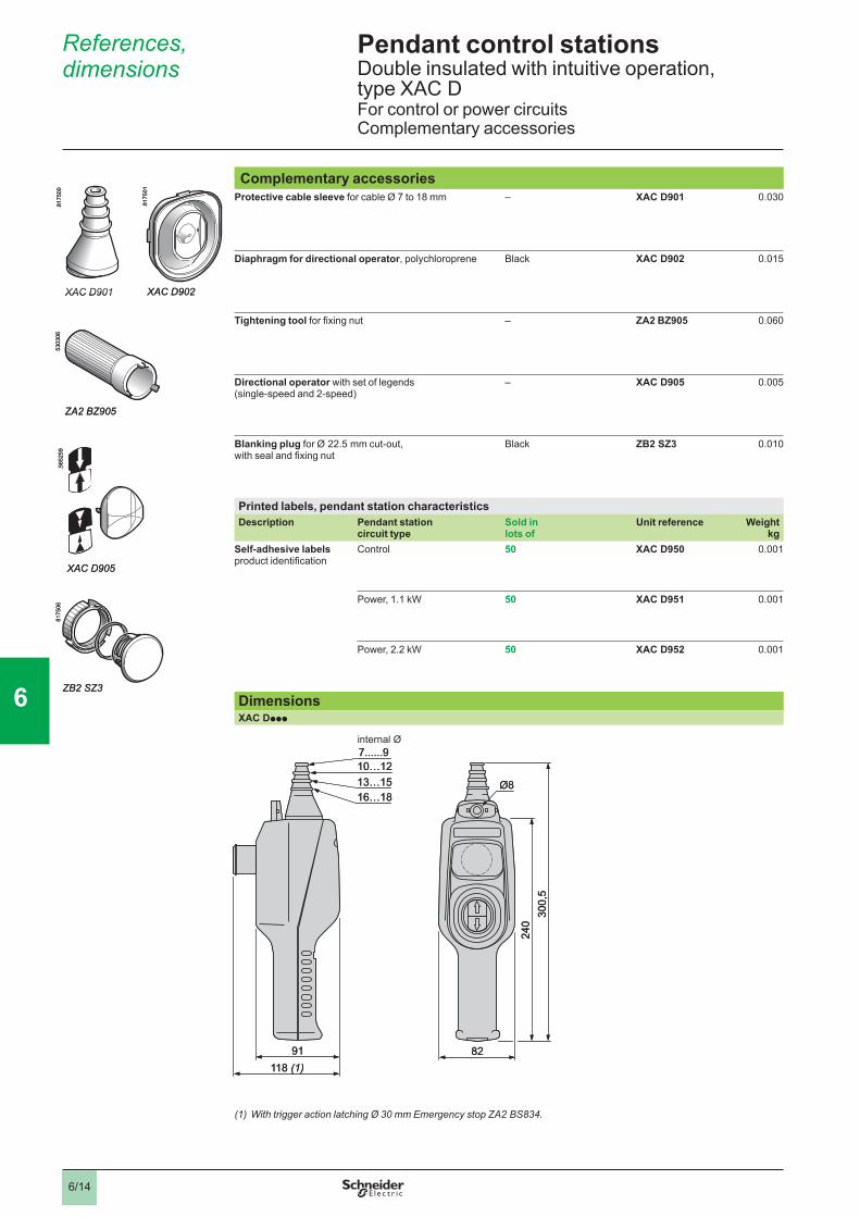
Pendant control stations 6 Double insulated with intuitive operation, type XAC DFor control or power circuitsComplementary accessories
Complementary accessoriesProtective cable sleeve for cable Ø 7 to 18 mm – XAC D901 0.030
Diaphragm for directional operator, polychloroprene Black XAC D902 0.015
Tightening tool for fi xing nut – ZA2 BZ905 0.060
Directional operator with set of legends (single-speed and 2-speed)
– XAC D905 0.005
Blanking plug for Ø 22.5 mm cut-out, with seal and fi xing nut
Black ZB2 SZ3 0.010
Printed labels, pendant station characteristicsDescription Pendant station
circuit typeSold inlots of
Unit reference Weightkg
Self-adhesive labelsproduct identifi cation
Control 50 XAC D950 0.001
Power, 1.1 kW 50 XAC D951 0.001
Power, 2.2 kW 50 XAC D952 0.001
DimensionsXAC Dppp
(1) With trigger action latching Ø 30 mm Emergency stop ZA2 BS834.
XAC D901
.817
500
XAC D901
.817
500
XAC D902
.817
501
XAC D902
.817
501
5303
06
ZA2 BZ905
5303
06
ZA2 BZ905
XAC D905
.565
259
XAC D905
.565
259
ZB2 SZ3
8175
06
ZB2 SZ3
8175
06
91
10…1213…1516…18
Ø8
82
300,
5
240
7......9
118 (1)91
10…1213…1516…18
Ø8
82
300,
5
240
7......9
118 (1)
References,dimensions 6
internal Ø
1
2
3
4
5
6
7
8
9
10
6/15
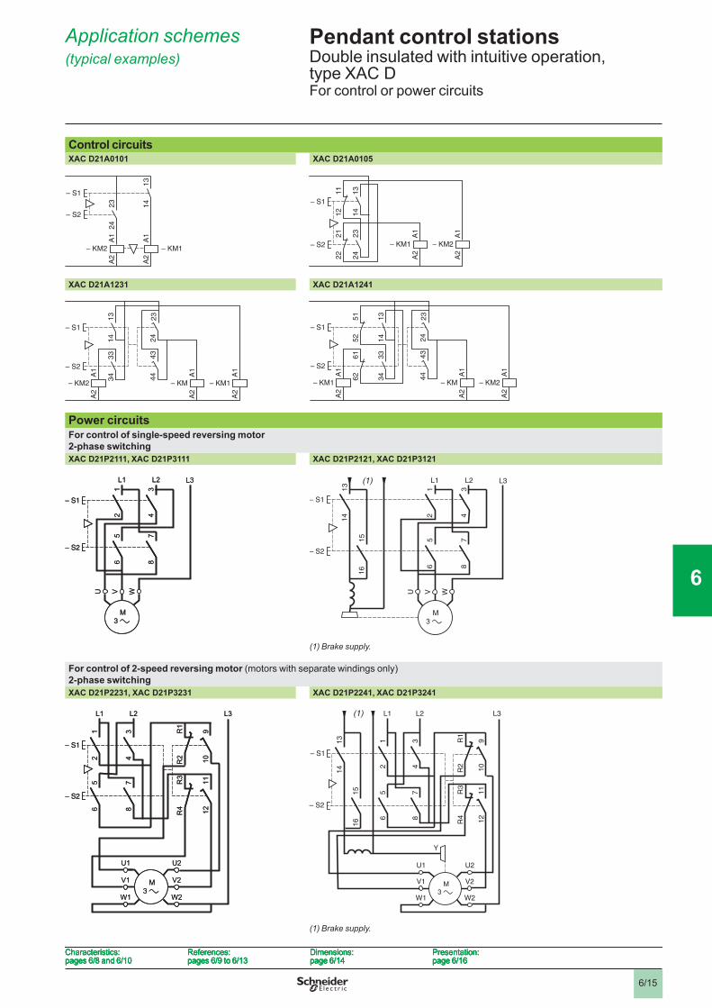
Pendant control stations 6 Double insulated with intuitive operation, type XAC DFor control or power circuits
Application schemes (typical examples) 6
Control circuitsXAC D21A0101 XAC D21A0105
XAC D21A1231 XAC D21A1241
Power circuitsFor control of single-speed reversing motor2-phase switchingXAC D21P2111, XAC D21P3111 XAC D21P2121, XAC D21P3121
(1) Brake supply.
For control of 2-speed reversing motor (motors with separate windings only)2-phase switchingXAC D21P2231, XAC D21P3231 XAC D21P2241, XAC D21P3241
(1) Brake supply.
– KM1
13
14
23
24
A1
A2
– KM2
– S1
A1
A2
– S2
– KM1
13
14
23
24
A1
A2
– KM2
– S1
A1
A2
– S2
13
14
11
12
23
24
21
22
A1
A2
– KM1
– S1
A1
A2
– KM2– S2
13
14
11
12
23
24
21
22
A1
A2
– KM1
– S1
A1
A2
– KM2– S2
24
43
44
13
23
14
33
34 A
1A
2
– KM1
A1
A2
– KM
– S1
A1
A2
– KM2
– S2
24
43
44
13
23
14
33
34 A
1A
2
– KM1
A1
A2
– KM
– S1
A1
A2
– KM2
– S2
24
43
44
13
23
14
51
52
33
34
61
62 A
1A
2
– KM2
A1
A2
– KM
– S1A
1A
2
– KM1
– S2
24
43
44
13
23
14
51
52
33
34
61
62 A
1A
2
– KM2
A1
A2
– KM
– S1A
1A
2
– KM1
– S2
L1 L2 L3
12
34
56
78
– S1
– S2
U V W
L1 L2 L3
12
34
56
78
– S1
– S2
U V W
L1 L2 L3
12
34
56
78
13
14
15
16
– S1
– S2
U V W
(1) L1 L2 L3
12
34
56
78
13
14
15
16
– S1
– S2
U V W
(1)
– S1
– S2
910
1112
R1
R2
R3
R4
56
78
12
34
U2
V2
W2
U1
V1
W1
L1 L2 L3
– S1
– S2
910
1112
R1
R2
R3
R4
56
78
12
34
U2
V2
W2
U1
V1
W1
L1 L2 L3
– S1
– S2
91
01
11
2
R1
R2
R3
R4
56
78
12
34
U2
V2
W2
U1
V1
W1
L1 L2 L3
13
14
15
16
Y
(1)
– S1
– S2
91
01
11
2
R1
R2
R3
R4
56
78
12
34
U2
V2
W2
U1
V1
W1
L1 L2 L3
13
14
15
16
Y
(1)
Characteristics:pages 6/8 and 6/10
References:pages 6/9 to 6/13
Dimensions:page 6/14
Presentation:page 6/16
Characteristics:pages 6/8 and 6/10
References:pages 6/9 to 6/13
Dimensions:page 6/14
Presentation:page 6/16
Characteristics:pages 6/8 and 6/10
References:pages 6/9 to 6/13
Dimensions:page 6/14
Presentation:page 6/16
Characteristics:pages 6/8 and 6/10
References:pages 6/9 to 6/13
Dimensions:page 6/14
Presentation:page 6/16
1
2
3
4
5
6
7
8
9
10
6/16
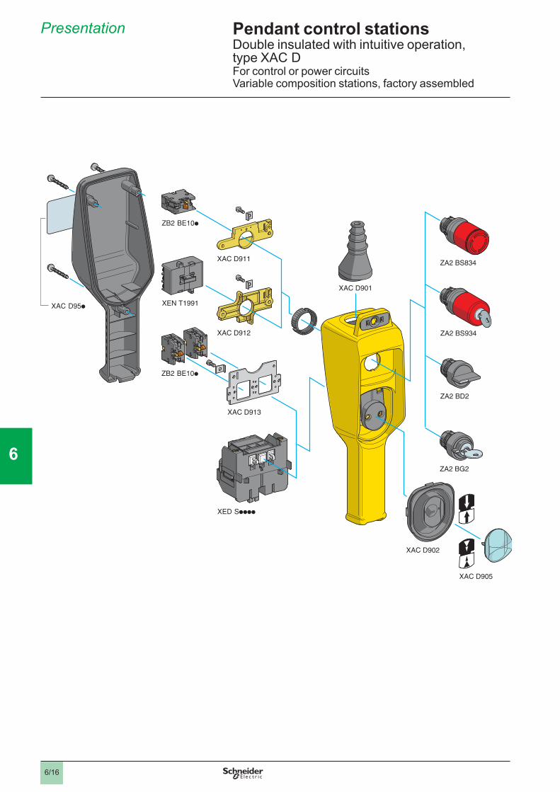
Pendant control stations 6 Double insulated with intuitive operation, type XAC DFor control or power circuitsVariable composition stations, factory assembled
Presentation 6
1
2
3
4
5
6
7
8
9
10
6/17
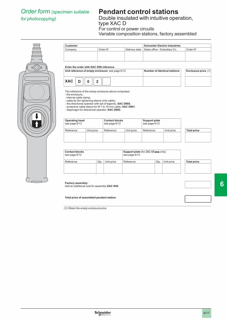
Pendant control stations 6 Double insulated with intuitive operation, type XAC DFor control or power circuitsVariable composition stations, factory assembled
D 0 2
Order form (specimen suitable for photocopying) 6
Customer Schneider Electric IndustriesCompany Order N° Delivery date Sales offi ce - Subsidiary Co. Order N°
Enter the order with XAC D09 referenceUnit reference of empty enclosure, see page 6/12 Number of identical stations Enclosure price (1)
XAC
The reference of the empty enclosure above comprises:- the enclosure, - internal cable clamp, - cable tie (for tightening sleeve onto cable), - the directional operator with set of legends, XAC D905, - protective cable sleeve for Ø 7 to 18 mm cable, XAC D901, - diaphragm for directional operator, XAC D902.
Operating headsee page 6/13
Contact blockssee page 6/12
Support platesee page 6/13
Reference Unit price Reference Unit price Reference Unit price Total price
Contact blockssee page 6/12
Support plate (for ZB2 BEppp only)see page 6/13
Reference Qty. Unit price Reference Qty. Unit price Total price
Factory assembly:Add an additional cost for assembly XAC 9VA
Total price of assembled pendant station
(1) Obtain the empty enclosure price.
1
2
3
4
5
6
7
8
9
10
6/18
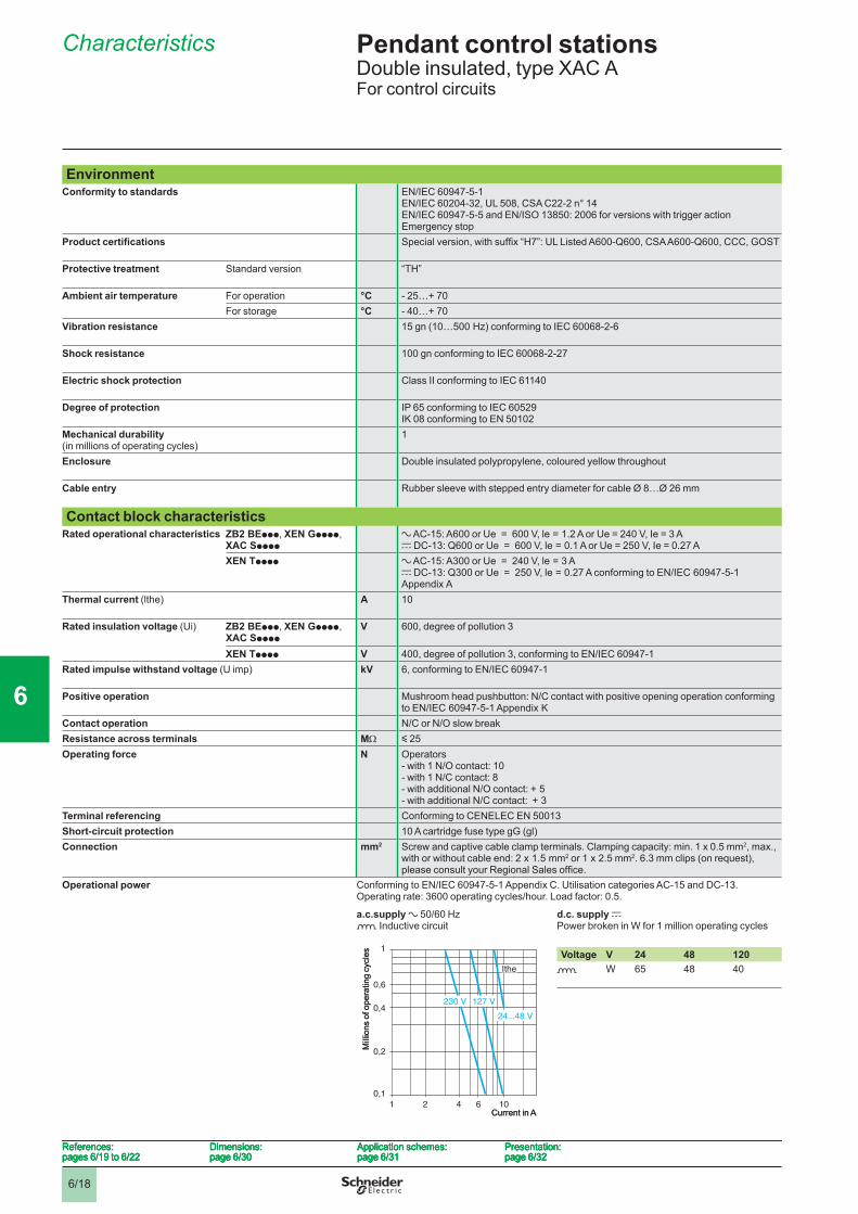
Pendant control stations 6 Double insulated, type XAC AFor control circuits
Characteristics 6
EnvironmentConformity to standards EN/IEC 60947-5-1
EN/IEC 60204-32, UL 508, CSA C22-2 n° 14EN/IEC 60947-5-5 and EN/ISO 13850: 2006 for versions with trigger action Emergency stop
Product certifi cations Special version, with suffi x “H7”: UL Listed A600-Q600, CSA A600-Q600, CCC, GOST
Protective treatment Standard version “TH”
Ambient air temperature For operation °C - 25…+ 70For storage °C - 40…+ 70
Vibration resistance 15 gn (10…500 Hz) conforming to IEC 60068-2-6
Shock resistance 100 gn conforming to IEC 60068-2-27
Electric shock protection Class II conforming to IEC 61140
Degree of protection IP 65 conforming to IEC 60529IK 08 conforming to EN 50102
Mechanical durability(in millions of operating cycles)
1
Enclosure Double insulated polypropylene, coloured yellow throughout
Cable entry Rubber sleeve with stepped entry diameter for cable Ø 8…Ø 26 mm
Contact block characteristicsRated operational characteristics ZB2 BEppp, XEN Gpppp,
XAC Spppp a AC-15: A600 or Ue = 600 V, le = 1.2 A or Ue = 240 V, Ie = 3 Ac DC-13: Q600 or Ue = 600 V, le = 0.1 A or Ue = 250 V, Ie = 0.27 A
XEN Tpppp a AC-15: A300 or Ue = 240 V, le = 3 Ac DC-13: Q300 or Ue = 250 V, le = 0.27 A conforming to EN/IEC 60947-5-1 Appendix A
Thermal current (lthe) A 10
Rated insulation voltage (Ui) ZB2 BEppp, XEN Gpppp, XAC Spppp
V 600, degree of pollution 3
XEN Tpppp V 400, degree of pollution 3, conforming to EN/IEC 60947-1Rated impulse withstand voltage (U imp) kV 6, conforming to EN/IEC 60947-1
Positive operation Mushroom head pushbutton: N/C contact with positive opening operation conforming to EN/IEC 60947-5-1 Appendix K
Contact operation N/C or N/O slow breakResistance across terminals MΩ y 25Operating force N Operators
- with 1 N/O contact: 10- with 1 N/C contact: 8- with additional N/O contact: + 5- with additional N/C contact: + 3
Terminal referencing Conforming to CENELEC EN 50013Short-circuit protection 10 A cartridge fuse type gG (gl)Connection mm2 Screw and captive cable clamp terminals. Clamping capacity: min. 1 x 0.5 mm2, max.,
with or without cable end: 2 x 1.5 mm2 or 1 x 2.5 mm2. 6.3 mm clips (on request), please consult your Regional Sales offi ce.
Operational power Conforming to EN/IEC 60947-5-1 Appendix C. Utilisation categories AC-15 and DC-13.Operating rate: 3600 operating cycles/hour. Load factor: 0.5.
a.c.supply a 50/60 Hzo Inductive circuit
d.c. supply c Power broken in W for 1 million operating cycles
Voltage V 24 48 120o W 65 48 40
1 2 4 6 10
0,1
0,2
0,4
0,6
1
230 V 127 V
24...48 V
Ithe
Mill
ions
of o
pera
ting
cycl
es
Current in A1 2 4 6 10
0,1
0,2
0,4
0,6
1
230 V 127 V
24...48 V
Ithe
Mill
ions
of o
pera
ting
cycl
es
Current in A
References:pages 6/19 to 6/22
Dimensions:page 6/30
Application schemes:page 6/31
Presentation:page 6/32
References:pages 6/19 to 6/22
Dimensions:page 6/30
Application schemes:page 6/31
Presentation:page 6/32
References:pages 6/19 to 6/22
Dimensions:page 6/30
Application schemes:page 6/31
Presentation:page 6/32
References:pages 6/19 to 6/22
Dimensions:page 6/30
Application schemes:page 6/31
Presentation:page 6/32
1
2
3
4
5
6
7
8
9
10
6/19
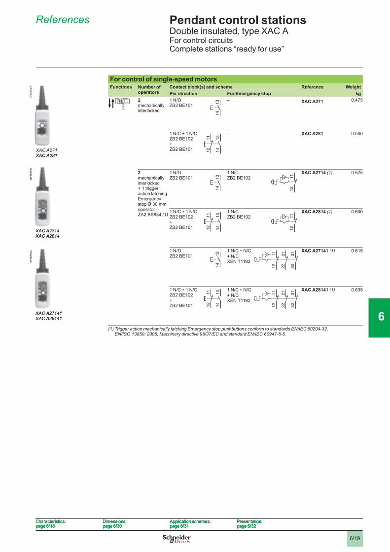
Pendant control stations 6 Double insulated, type XAC AFor control circuitsComplete stations “ready for use”
References 6
For control of single-speed motorsFunctions Number of
operatorsContact block(s) and scheme Reference WeightPer direction For Emergency stop kg
2 mechanically interlocked
1 N/OZB2 BE101
– XAC A271 0.475
1 N/C + 1 N/OZB2 BE102+ZB2 BE101
– XAC A281 0.500
2 mechanically interlocked+ 1 trigger action latching Emergency stop Ø 30 mm operator ZA2 BS834 (1)
1 N/OZB2 BE101
1 N/CZB2 BE102
XAC A2714 (1) 0.575
1 N/C + 1 N/OZB2 BE102+ZB2 BE101
1 N/CZB2 BE102
XAC A2814 (1) 0.600
1 N/OZB2 BE101
1 N/C + N/C+ N/C XEN T1192
XAC A27141 (1) 0.615
1 N/C + 1 N/OZB2 BE102+ZB2 BE101
1 N/C + N/C+ N/C XEN T1192
XAC A28141 (1) 0.635
(1) Trigger action mechanically latching Emergency stop pushbuttons conform to standards EN/IEC 60204-32, EN/ISO 13850: 2006, Machinery directive 98/37/EC and standard EN/IEC 60947-5-5.
13
14
13
14
XAC A271XAC A281
DF5
6552
3
XAC A271XAC A281
DF5
6552
3
13
14
11
12
13
14
11
12
13
14
13
14
11
12
11
12
XAC A2714XAC A2814
DF5
6552
4
XAC A2714XAC A2814
DF5
6552
4
13
14
11
12
13
14
11
12
11
12
11
12
13
14
13
14
11
12
21
22
31
32
11
12
21
22
31
32
XAC A27141XAC A28141
DF5
6552
4
XAC A27141XAC A28141
DF5
6552
4
13
14
11
12
13
14
11
12
11
12
21
22
31
32
11
12
21
22
31
32
Characteristics:page 6/18
Dimensions:page 6/30
Application schemes:page 6/31
Presentation:page 6/32
Characteristics:page 6/18
Dimensions:page 6/30
Application schemes:page 6/31
Presentation:page 6/32
Characteristics:page 6/18
Dimensions:page 6/30
Application schemes:page 6/31
Presentation:page 6/32
Characteristics:page 6/18
Dimensions:page 6/30
Application schemes:page 6/31
Presentation:page 6/32
1
2
3
4
5
6
7
8
9
10
6/20
Pendant control stations 6 Double insulated, type XAC AFor control circuitsComplete stations “ready for use”
References (continued) 6
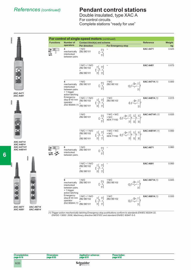
For control of single-speed motors (continued)Functions Number of
operatorsContact block(s) and scheme Reference WeightPer direction For Emergency stop kg
4 mechanically interlocked between pairs
1 N/OZB2 BE101
– XAC A471 0.625
1 N/C + 1 N/OZB2 BE102+ZB2 BE101
– XAC A481 0.675
4 mechanically interlocked between pairs + 1 trigger action latching Emergency stop Ø 40 mm operator ZA2 BS844 (1)
1 N/O ZB2 BE101
1 N/CZB2 BE102
XAC A4714 (1) 0.800
1 N/C + 1 N/OZB2 BE102+ZB2 BE101
1 N/CZB2 BE102
XAC A4814 (1) 0.815
1 N/O ZB2 BE101
1 N/C + N/C+ N/C XEN T1192
XAC A47141 (1) 0.835
1 N/C + 1 N/O ZB2 BE102+ ZB2 BE101
1 N/C + N/C+ N/C XEN T1192
XAC A48141 (1) 0.850
6mechanically interlocked between pairs
1 N/O ZB2 BE101
– XAC A671 0.860
1 N/C + 1 N/O ZB2 BE102+ ZB2 BE101
– XAC A681 0.950
6 mechanically interlocked between pairs+ 1 trigger action latching Emergency stop Ø 40 mm operator ZA2 BS844 (1)
1 N/O ZB2 BE101
1 N/CZB2 BE102
XAC A6714 (1) 0.845
1 N/C + 1 N/OZB2 BE102+ZB2 BE101
1 N/CZB2 BE102
XAC A6814 (1) 0.935
(1) Trigger action mechanically latching Emergency stop pushbuttons conform to standards EN/IEC 60204-32, EN/ISO 13850: 2006, Machinery directive 98/37/EC and standard EN/IEC 60947-5-5.
13
14
13
14
XAC A471XAC A481
DF5
6552
5
XAC A471XAC A481
DF5
6552
5
13
14
11
12
13
14
11
12
13
14
13
14
11
12
11
12
XAC A4714XAC A4814XAC A47141XAC A48141
5302
26
XAC A4714XAC A4814XAC A47141XAC A48141
5302
26 13
14
11
12
13
14
11
12
11
12
11
12
13
14
13
14
11
12
21
22
31
32
11
12
21
22
31
32
13
14
11
12
13
14
11
12
11
12
21
22
31
32
11
12
21
22
31
32
13
14
13
14
XAC A671XAC A681
5302
23
XAC A6714XAC A6814
5302
24
XAC A671XAC A681
5302
23
XAC A6714XAC A6814
5302
24
13
14
11
12
13
14
11
12
13
14
13
14
11
12
11
12
13
14
11
12
13
14
11
12
11
12
11
12
Characteristics:page 6/18
Dimensions:page 6/30
Application schemes:page 6/31
Presentation:page 6/32
Characteristics:page 6/18
Dimensions:page 6/30
Application schemes:page 6/31
Presentation:page 6/32
Characteristics:page 6/18
Dimensions:page 6/30
Application schemes:page 6/31
Presentation:page 6/32
Characteristics:page 6/18
Dimensions:page 6/30
Application schemes:page 6/31
Presentation:page 6/32
1
2
3
4
5
6
7
8
9
10
6/21
Pendant control stations 6 Double insulated, type XAC AFor control circuitsComplete stations “ready for use”
References (continued) 6
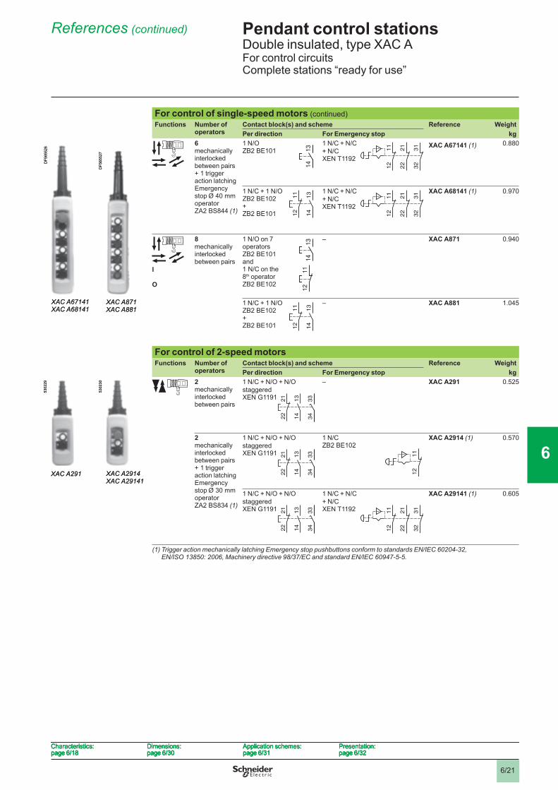
For control of single-speed motors (continued)Functions Number of
operatorsContact block(s) and scheme Reference WeightPer direction For Emergency stop kg
6 mechanically interlocked between pairs+ 1 trigger action latching Emergency stop Ø 40 mm operator ZA2 BS844 (1)
1 N/OZB2 BE101
1 N/C + N/C+ N/C XEN T1192
XAC A67141 (1) 0.880
1 N/C + 1 N/OZB2 BE102+ZB2 BE101
1 N/C + N/C+ N/C XEN T1192
XAC A68141 (1) 0.970
I
O
8mechanically interlocked between pairs
1 N/O on 7 operators ZB2 BE101 and1 N/C on the 8th operator ZB2 BE102
– XAC A871 0.940
1 N/C + 1 N/OZB2 BE102+ZB2 BE101
– XAC A881 1.045
For control of 2-speed motors Functions Number of
operatorsContact block(s) and scheme Reference WeightPer direction For Emergency stop kg
2mechanically interlocked between pairs
1 N/C + N/O + N/Ostaggered XEN G1191
– XAC A291 0.525
2 mechanically interlocked between pairs + 1 trigger action latching Emergency stop Ø 30 mm operator ZA2 BS834 (1)
1 N/C + N/O + N/Ostaggered XEN G1191
1 N/CZB2 BE102
XAC A2914 (1) 0.570
1 N/C + N/O + N/Ostaggered XEN G1191
1 N/C + N/C+ N/C XEN T1192
XAC A29141 (1) 0.605
(1) Trigger action mechanically latching Emergency stop pushbuttons conform to standards EN/IEC 60204-32, EN/ISO 13850: 2006, Machinery directive 98/37/EC and standard EN/IEC 60947-5-5.
13
14
13
14
11
12
21
22
31
32
11
12
21
22
31
32
XAC A67141XAC A68141
DF5
6552
6
XAC A67141XAC A68141
DF5
6552
6
13
14
11
12
13
14
11
12
11
12
21
22
31
32
11
12
21
22
31
32
13
14
11
12
13
14
11
12
XAC A871XAC A881
DF5
6552
7
XAC A871XAC A881
DF5
6552
7
13
14
11
12
13
14
11
12
13
14
21
22
33
34
13
14
21
22
33
34
XAC A291
5302
29
XAC A291
5302
29
13
14
21
22
33
34
13
14
21
22
33
34
11
12
11
12XAC A2914
XAC A29141
5302
30
XAC A2914XAC A29141
5302
30
13
14
21
22
33
34
13
14
21
22
33
34
11
12
21
22
31
32
11
12
21
22
31
32
Characteristics:page 6/18
Dimensions:page 6/30
Application schemes:page 6/31
Presentation:page 6/32
Characteristics:page 6/18
Dimensions:page 6/30
Application schemes:page 6/31
Presentation:page 6/32
Characteristics:page 6/18
Dimensions:page 6/30
Application schemes:page 6/31
Presentation:page 6/32
Characteristics:page 6/18
Dimensions:page 6/30
Application schemes:page 6/31
Presentation:page 6/32
1
2
3
4
5
6
7
8
9
10
6/22
Pendant control stations 6 Double insulated, type XAC AFor control circuitsComplete stations “ready for use”
References (continued) 6
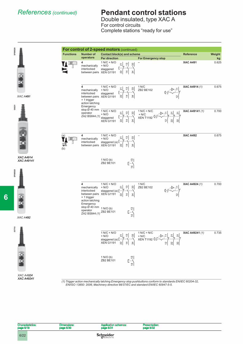
For control of 2-speed motors (continued)Functions Number of
operatorsContact block(s) and scheme Reference WeightPer direction For Emergency stop kg
4mechanically interlocked between pairs
1 N/C + N/O+ N/Ostaggered XEN G1191
– XAC A491 0.625
4 mechanically interlocked between pairs+ 1 trigger action latching Emergency stop Ø 40 mm operator ZA2 BS844 (1)
1 N/C + N/O + N/Ostaggered XEN G1191
1 N/CZB2 BE102
XAC A4914 (1) 0.675
1 N/C + N/O + N/Ostaggered XEN G1191
1 N/C + N/C + N/C XEN T1192
XAC A49141 (1) 0.700
(a)
(b)
4mechanically interlocked between pairs
1 N/C + N/O + N/Ostaggered (a) XEN G1191
– XAC A492 0.675
1 N/O (b)ZB2 BE101
4 mechanically interlocked between pairs + 1 trigger action latching Emergency stop Ø 40 mm operator ZA2 BS844 (1)
1 N/C + N/O + N/Ostaggered (a) XEN G1191
1 N/CZB2 BE102
XAC A4924 (1) 0.700
1 N/O (b)ZB2 BE101
1 N/C + N/O + N/Ostaggered (a) XEN G1191
1 N/C + N/C+ N/C XEN T1192
XAC A49241 (1) 0.735
1 N/O (b)ZB2 BE101
(1) Trigger action mechanically latching Emergency stop pushbuttons conform to standards EN/IEC 60204-32, EN/ISO 13850: 2006, Machinery directive 98/37/EC and standard EN/IEC 60947-5-5.
13
14
21
22
33
34
13
14
21
22
33
34
XAC A491
DF5
6552
8
XAC A491
DF5
6552
8
13
14
21
22
33
34
13
14
21
22
33
34
11
12
11
12
XAC A4914XAC A49141
5302
31
XAC A4914XAC A49141
5302
31
13
14
21
22
33
34
13
14
21
22
33
34
11
12
21
22
31
32
11
12
21
22
31
32
13
14
21
22
33
34
13
14
21
22
33
34
XAC A492
DF5
6552
8
XAC A492
DF5
6552
8
13
14
13
14
13
14
21
22
33
34
13
14
21
22
33
34
11
12
11
12
XAC A4924XAC A49241
5377
43
XAC A4924XAC A49241
5377
43
13
14
13
14
13
14
21
22
33
34
13
14
21
22
33
34
11
12
21
22
31
32
11
12
21
22
31
32
13
14
13
14
Characteristics:page 6/18
Dimensions:page 6/30
Application schemes:page 6/31
Presentation:page 6/32
Characteristics:page 6/18
Dimensions:page 6/30
Application schemes:page 6/31
Presentation:page 6/32
Characteristics:page 6/18
Dimensions:page 6/30
Application schemes:page 6/31
Presentation:page 6/32
Characteristics:page 6/18
Dimensions:page 6/30
Application schemes:page 6/31
Presentation:page 6/32
1
2
3
4
5
6
7
8
9
10
6/23
Pendant control stations 6 Double insulated, type XAC AFor control circuitsEmpty enclosures
References 6
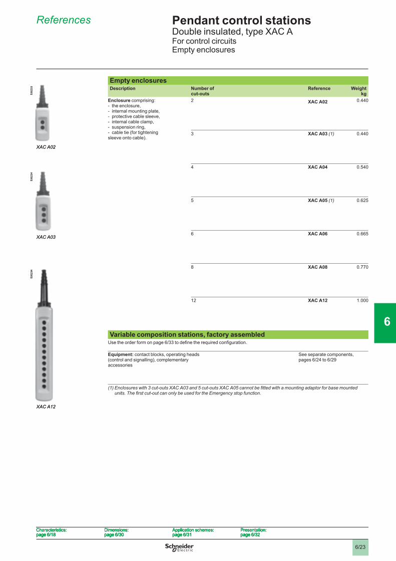
Empty enclosuresDescription Number of
cut-outsReference Weight
kgEnclosure comprising:- the enclosure, - internal mounting plate, - protective cable sleeve, - internal cable clamp, - suspension ring, - cable tie (for tightening sleeve onto cable).
2 XAC A02 0.440
3 XAC A03 (1) 0.440
4 XAC A04 0.540
5 XAC A05 (1) 0.625
6 XAC A06 0.665
8 XAC A08 0.770
12 XAC A12 1.000
Variable composition stations, factory assembledUse the order form on page 6/33 to defi ne the required confi guration.
Equipment: contact blocks, operating heads (control and signalling), complementary accessories
See separate components,pages 6/24 to 6/29
(1) Enclosures with 3 cut-outs XAC A03 and 5 cut-outs XAC A05 cannot be fi tted with a mounting adaptor for base mounted units. The fi rst cut-out can only be used for the Emergency stop function.
XAC A02
5302
33
XAC A02
5302
33
XAC A03
5302
34
XAC A03
5302
34
XAC A12
5302
34
XAC A12
5302
34
Characteristics:page 6/18
Dimensions:page 6/30
Application schemes:page 6/31
Presentation:page 6/32
Characteristics:page 6/18
Dimensions:page 6/30
Application schemes:page 6/31
Presentation:page 6/32
Characteristics:page 6/18
Dimensions:page 6/30
Application schemes:page 6/31
Presentation:page 6/32
Characteristics:page 6/18
Dimensions:page 6/30
Application schemes:page 6/31
Presentation:page 6/32
1
2
3
4
5
6
7
8
9
10
6/24
Pendant control stations 6 Double insulated, type XAC AFor control circuitsSeparate components and spare parts
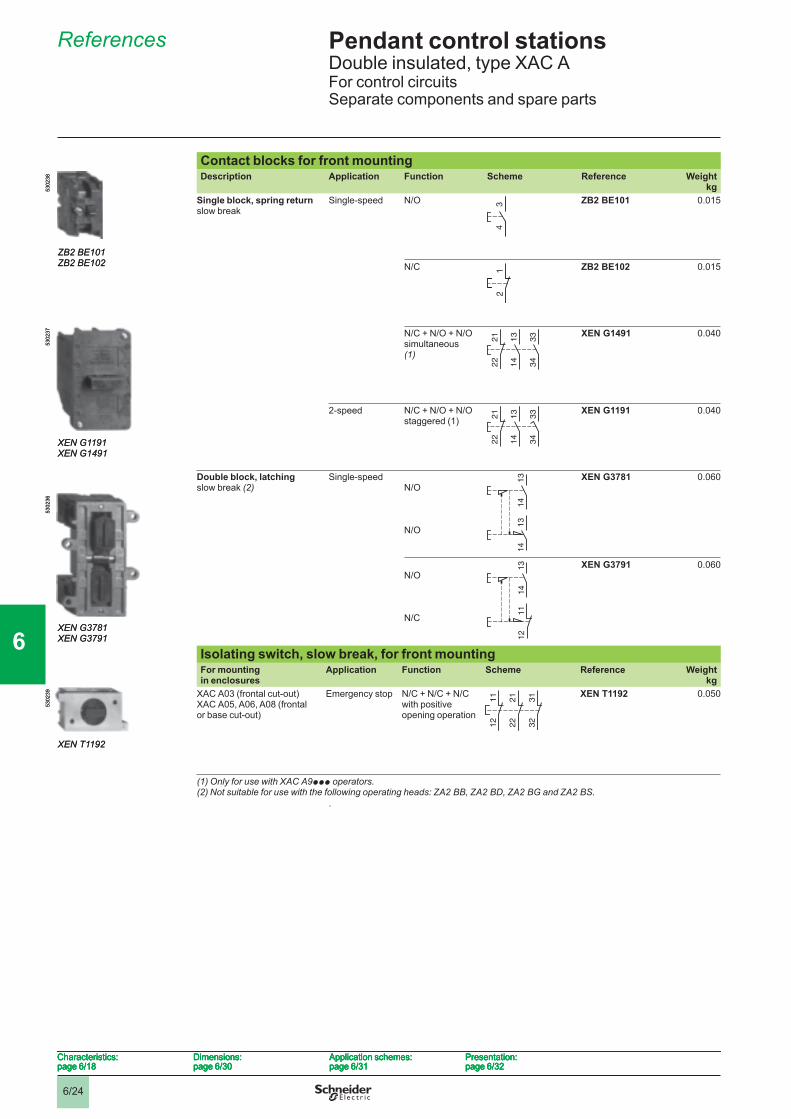
References 6
Contact blocks for front mountingDescription Application Function Scheme Reference Weight
kgSingle block, spring return slow break
Single-speed N/O ZB2 BE101 0.015
N/C ZB2 BE102 0.015
N/C + N/O + N/O simultaneous (1)
XEN G1491 0.040
2-speed N/C + N/O + N/O staggered (1)
XEN G1191 0.040
Double block, latching slow break (2)
Single-speedN/O
N/O
XEN G3781 0.060
N/O
N/C
XEN G3791 0.060
Isolating switch, slow break, for front mountingFor mounting in enclosures
Application Function Scheme Reference Weightkg
XAC A03 (frontal cut-out)XAC A05, A06, A08 (frontal or base cut-out)
Emergency stop N/C + N/C + N/C with positive opening operation
XEN T1192 0.050
(1) Only for use with XAC A9ppp operators.(2) Not suitable for use with the following operating heads: ZA2 BB, ZA2 BD, ZA2 BG and ZA2 BS.
.
34
34
ZB2 BE101ZB2 BE102
5302
38
ZB2 BE101ZB2 BE102
5302
38
2 1
2 1
13
14
33
34
21
22
13
14
33
34
21
22
13
14
33
34
21
22
13
14
33
34
21
22
XEN G1191XEN G1491
5302
37
XEN G1191XEN G1491
5302
37
13
14
13
14
13
14
13
14
XEN G3781XEN G3791
5302
36
XEN G3781XEN G3791
5302
36
13
14
11
12
13
14
11
12
11
12
21
22
31
32
11
12
21
22
31
32
XEN T1192
5302
39
XEN T1192
5302
39
Characteristics:page 6/18
Dimensions:page 6/30
Application schemes:page 6/31
Presentation:page 6/32
Characteristics:page 6/18
Dimensions:page 6/30
Application schemes:page 6/31
Presentation:page 6/32
Characteristics:page 6/18
Dimensions:page 6/30
Application schemes:page 6/31
Presentation:page 6/32
Characteristics:page 6/18
Dimensions:page 6/30
Application schemes:page 6/31
Presentation:page 6/32
1
2
3
4
5
6
7
8
9
10
6/25
Pendant control stations 6 Double insulated, type XAC AFor control circuitsSeparate components and spare parts
References (continued) 6
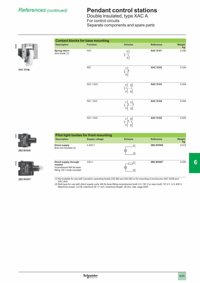
Contact blocks for base mountingDescription Function Scheme Reference Weight
kgSpring returnslow break (1)
N/O XAC S101 0.030
N/C XAC S102 0.030
N/O + N/O XAC S103 0.045
N/C + N/C XAC S104 0.045
N/C + N/O XAC S105 0.045
Pilot light bodies for front mountingDescription Supply voltage Scheme Reference Weight
kgDirect supplyBulb not included (2)
y 400 V ZB2 BV006 0.015
Direct supply, through resistorIncandescent BA 9s base fi tting 130 V bulb included
230 V ZB2 BV007 0.020
(1) Not suitable for use with 3-position operating heads ZA2 BD and ZA2 BG or for mounting in enclosures XAC A039 and XAC A03.
(2) Bulb type for use with direct supply units: BA 9s base fi tting incandescent bulb U y 130 V or neon bulb 110 V y U y 400 V. Maximum power: 2.6 W, maximum Ø: 11 mm, maximum length: 28 mm. See page 6/26 .
13
14
13
14
XAC S10p
5302
40
XAC S10p
5302
40
11
12
11
12
23
24
13
14
23
24
13
14
11
12
21
22
11
12
21
22
11
12
23
24
11
12
23
24
X1
X2
X1
X2
ZB2 BV006
5302
41
ZB2 BV006
5302
41
X1
X2
X1
X2
ZB2 BV007
5302
42
ZB2 BV007
5302
42
1
2
3
4
5
6
7
8
9
10
6/26
Pendant control stations 6 Double insulated, type XAC AFor control circuitsSeparate components and spare parts
References (continued) 6
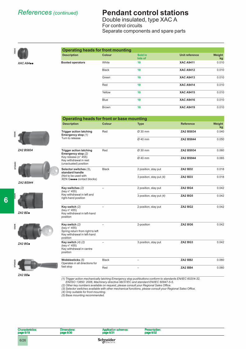
Operating heads for front mountingDescription Colour Sold in
lots ofUnit reference Weight
kgBooted operators White 10 XAC A9411 0.010
Black 10 XAC A9412 0.010
Green 10 XAC A9413 0.010
Red 10 XAC A9414 0.010
Yellow 10 XAC A9415 0.010
Blue 10 XAC A9416 0.010
Brown 10 XAC A9419 0.010
Operating heads for front or base mountingDescription Colour Type Reference Weight
kgTrigger action latching Emergency stop (1) Turn to release
Red Ø 30 mm ZA2 BS834 0.040
Ø 40 mm ZA2 BS844 0.050
Trigger action latching Emergency stop (2)Key release (n° 455) Key withdrawal in rest (unactuated) position
Red Ø 30 mm ZA2 BS934 0.060
Ø 40 mm ZA2 BS944 0.065
Selector switches (3), standard handle(Not to be used with XEN Gpppp contact blocks)
Black 2 position, stay put ZA2 BD2 0.018
3 position, stay put (4) ZA2 BD3 0.018
Key switches (2)(key n° 455)Key withdrawal in left and right-hand position
– 2 position, stay put ZA2 BG4 0.042
3 position, stay put (4) ZA2 BG5 0.042
Key switch (2)(key n° 455)Key withdrawal in left-hand position
– 2 position, stay put ZA2 BG2 0.042
Key switch (2)(key n° 455)Spring return from right to leftKey withdrawal in left-hand position
– 2-position ZA2 BG6 0.042
Key switch (4) (2)(key n° 455)Key withdrawal in centre position
– 3 position, stay put ZA2 BG3 0.042
Wobblesticks (5) Operates in all directions for fast stop
Black – ZA2 BB2 0.060
Red – ZA2 BB4 0.060
(1) Trigger action mechanically latching Emergency stop pushbuttons conform to standards EN/IEC 60204-32, EN/ISO 13850: 2006, Machinery directive 98/37/EC and standard EN/IEC 60947-5-5.
(2) Other key numbers available on request, please consult your Regional Sales Offi ce.(3) Selector switches available with other mechanical functions, please consult your Regional Sales Offi ce.(4) Only suitable for front mounting.(5) Base mounting recommended.
XAC A94pp
5302
43
XAC A94pp
5302
43
ZA2 BS834
5302
49
ZA2 BS834
5302
49
ZA2 BS944
DF5
3849
3
ZA2 BS944
DF5
3849
3
ZA2 BDp
5302
45
ZA2 BDp
5302
45
ZA2 BGp
5302
46
ZA2 BGp
5302
46
ZA2 BBp
DF5
6552
9
ZA2 BBp
DF5
6552
9
Characteristics:page 6/18
Dimensions:page 6/30
Application schemes:page 6/31
Presentation:page 6/32
Characteristics:page 6/18
Dimensions:page 6/30
Application schemes:page 6/31
Presentation:page 6/32
Characteristics:page 6/18
Dimensions:page 6/30
Application schemes:page 6/31
Presentation:page 6/32
Characteristics:page 6/18
Dimensions:page 6/30
Application schemes:page 6/31
Presentation:page 6/32
1
2
3
4
5
6
7
8
9
10
6/27
Pendant control stations 6 Double insulated, type XAC AFor control circuitsSeparate components and spare parts
References (continued) 6
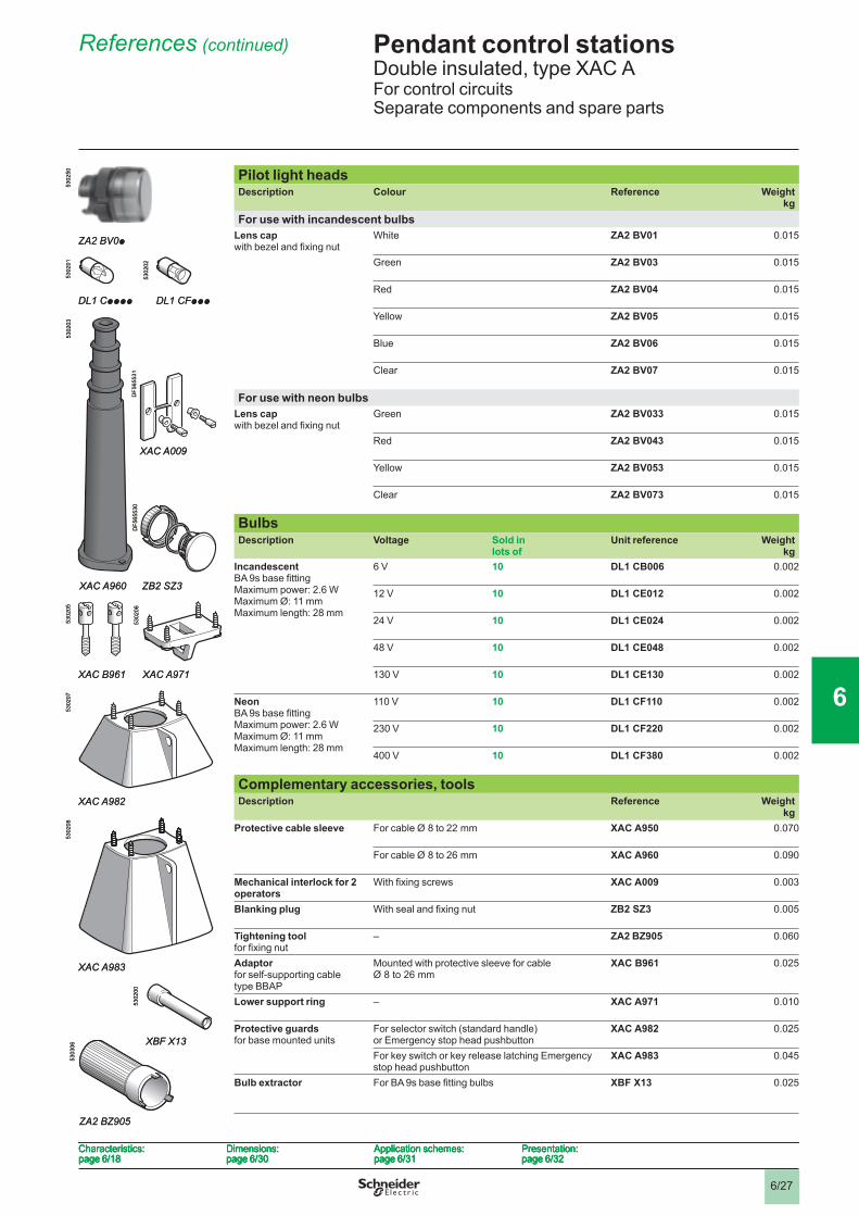
Pilot light headsDescription Colour Reference Weight
kgFor use with incandescent bulbs
Lens cap with bezel and fi xing nut
White ZA2 BV01 0.015
Green ZA2 BV03 0.015
Red ZA2 BV04 0.015
Yellow ZA2 BV05 0.015
Blue ZA2 BV06 0.015
Clear ZA2 BV07 0.015
For use with neon bulbsLens cap with bezel and fi xing nut
Green ZA2 BV033 0.015
Red ZA2 BV043 0.015
Yellow ZA2 BV053 0.015
Clear ZA2 BV073 0.015
Bulbs Description Voltage Sold in
lots ofUnit reference Weight
kgIncandescentBA 9s base fi ttingMaximum power: 2.6 WMaximum Ø: 11 mmMaximum length: 28 mm
6 V 10 DL1 CB006 0.002
12 V 10 DL1 CE012 0.002
24 V 10 DL1 CE024 0.002
48 V 10 DL1 CE048 0.002
130 V 10 DL1 CE130 0.002
NeonBA 9s base fi ttingMaximum power: 2.6 WMaximum Ø: 11 mmMaximum length: 28 mm
110 V 10 DL1 CF110 0.002
230 V 10 DL1 CF220 0.002
400 V 10 DL1 CF380 0.002
Complementary accessories, toolsDescription Reference Weight
kgProtective cable sleeve For cable Ø 8 to 22 mm XAC A950 0.070
For cable Ø 8 to 26 mm XAC A960 0.090
Mechanical interlock for 2 operators
With fi xing screws XAC A009 0.003
Blanking plug With seal and fi xing nut ZB2 SZ3 0.005
Tightening tool for fi xing nut
– ZA2 BZ905 0.060
Adaptor for self-supporting cabletype BBAP
Mounted with protective sleeve for cable Ø 8 to 26 mm
XAC B961 0.025
Lower support ring – XAC A971 0.010
Protective guards for base mounted units
For selector switch (standard handle)or Emergency stop head pushbutton
XAC A982 0.025
For key switch or key release latching Emergency stop head pushbutton
XAC A983 0.045
Bulb extractor For BA 9s base fi tting bulbs XBF X13 0.025
ZA2 BV0p
5302
50
ZA2 BV0p
5302
50
DL1 Cpppp
5302
01
DL1 CFppp
5302
02
DL1 Cpppp
5302
01
DL1 CFppp
5302
02
XAC A960
5302
03
XAC A009
ZB2 SZ3
DF5
6553
1D
F565
530
XAC A960
5302
03
XAC A009
ZB2 SZ3
DF5
6553
1D
F565
530
5303
06
ZA2 BZ905
5303
06
ZA2 BZ905
XAC B961
5302
05
XAC A971
5302
06
XAC B961
5302
05
XAC A971
5302
06
XAC A982
5302
07
XAC A982
5302
07
XAC A983
5302
08
XAC A983
5302
08
XBF X13
5302
00
XBF X13
5302
00
Characteristics:page 6/18
Dimensions:page 6/30
Application schemes:page 6/31
Presentation:page 6/32
Characteristics:page 6/18
Dimensions:page 6/30
Application schemes:page 6/31
Presentation:page 6/32
Characteristics:page 6/18
Dimensions:page 6/30
Application schemes:page 6/31
Presentation:page 6/32
Characteristics:page 6/18
Dimensions:page 6/30
Application schemes:page 6/31
Presentation:page 6/32
1
2
3
4
5
6
7
8
9
10
6/28
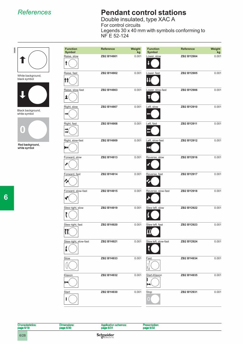
Pendant control stations 6 Double insulated, type XAC AFor control circuitsLegends 30 x 40 mm with symbols conforming toNF E 52-124
References 6
Function Symbol
Reference Weightkg
Function Symbol
Reference Weightkg
Raise, slow ZB2 BY4901 0.001 Lower, slow ZB2 BY2904 0.001
Raise, fast ZB2 BY4902 0.001 Lower, fast ZB2 BY2905 0.001
Raise, slow-fast ZB2 BY4903 0.001 Lower, slow-fast ZB2 BY2906 0.001
Right, slow ZB2 BY4907 0.001 Left, slow ZB2 BY2910 0.001
Right, fast ZB2 BY4908 0.001 Left, fast ZB2 BY2911 0.001
Right, slow-fast ZB2 BY4909 0.001 Left, slow-fast ZB2 BY2912 0.001
Forward, slow ZB2 BY4913 0.001 Reverse, slow ZB2 BY2916 0.001
Forward, fast ZB2 BY4914 0.001 Reverse, fast ZB2 BY2917 0.001
Forward, slow-fast ZB2 BY4915 0.001 Reverse, slow-fast ZB2 BY2918 0.001
Slew right, slow ZB2 BY4919 0.001 Slew left, slow ZB2 BY2922 0.001
Slew right, fast ZB2 BY4920 0.001 Slew left, fast ZB2 BY2923 0.001
Slew right, slow-fast ZB2 BY4921 0.001 Slew left, slow-fast ZB2 BY2924 0.001
Slow ZB2 BY4933 0.001 Fast ZB2 BY4934 0.001
Klaxon ZB2 BY4932 0.001 Start-Klaxon ZB2 BY4935 0.001
Start ZB2 BY4930 0.001 Stop ZB2 BY2931 0.001
0
White background, black symbol
5302
09
Black background, white symbol
Red background, white symbol
0
White background, black symbol
5302
09
Black background, white symbol
Red background, white symbol
00
Characteristics:page 6/18
Dimensions:page 6/30
Application schemes:page 6/31
Presentation:page 6/32
Characteristics:page 6/18
Dimensions:page 6/30
Application schemes:page 6/31
Presentation:page 6/32
Characteristics:page 6/18
Dimensions:page 6/30
Application schemes:page 6/31
Presentation:page 6/32
Characteristics:page 6/18
Dimensions:page 6/30
Application schemes:page 6/31
Presentation:page 6/32
1
2
3
4
5
6
7
8
9
10
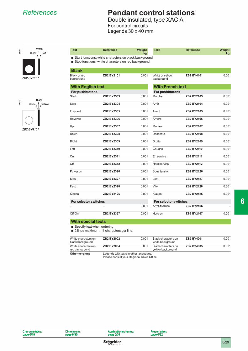
6/29
Pendant control stations 6 Double insulated, type XAC AFor control circuitsLegends 30 x 40 mm
References 6
Text Reference Weightkg
Text Reference Weightkg
Start functions: white characters on black background Stop functions: white characters on red background
bb
BlankBlack or red background
ZB2 BY2101 0.001 White or yellow background
ZB2 BY4101 0.001
With English text With French textFor pushbuttons For pushbuttons
Start ZB2 BY2303 0.001 Marche ZB2 BY2103 0.001
Stop ZB2 BY2304 0.001 Arrêt ZB2 BY2104 0.001
Forward ZB2 BY2305 0.001 Avant ZB2 BY2105 0.001
Reverse ZB2 BY2306 0.001 Arrière ZB2 BY2106 0.001
Up ZB2 BY2307 0.001 Montée ZB2 BY2107 0.001
Down ZB2 BY2308 0.001 Descente ZB2 BY2108 0.001
Right ZB2 BY2309 0.001 Droite ZB2 BY2109 0.001
Left ZB2 BY2310 0.001 Gauche ZB2 BY2110 0.001
On ZB2 BY2311 0.001 En service ZB2 BY2111 0.001
Off ZB2 BY2312 0.001 Hors service ZB2 BY2112 0.001
Power on ZB2 BY2326 0.001 Sous tension ZB2 BY2126 0.001
Slow ZB2 BY2327 0.001 Lent ZB2 BY2127 0.001
Fast ZB2 BY2328 0.001 Vite ZB2 BY2128 0.001
Klaxon ZB2 BY2125 0.001 Klaxon ZB2 BY2125 0.001
For selector switches For selector switches– – 0.001 Arrêt-Marche ZB2 BY2166 –
Off-On ZB2 BY2367 0.001 Hors-en ZB2 BY2167 0.001
With special texts Specify text when ordering, 2 lines maximum, 11 characters per line.
bb
White characters on black background
ZB2 BY2002 0.001 Black characters on white background
ZB2 BY4001 0.001
White characters on red background
ZB2 BY2004 0.001 Black characters on yellow background
ZB2 BY4005 0.001
Other versions Legends with texts in other languages.Please consult your Regional Sales Offi ce.
5302
11
ZB2 BY2101
RedWhite
Black5302
11
ZB2 BY2101
RedWhite
Black
5302
12
ZB2 BY4101
YellowBlack
White5302
12
ZB2 BY4101
YellowBlack
White
Characteristics:page 6/18
Dimensions:page 6/30
Application schemes:page 6/31
Presentation:page 6/32
Characteristics:page 6/18
Dimensions:page 6/30
Application schemes:page 6/31
Presentation:page 6/32
Characteristics:page 6/18
Dimensions:page 6/30
Application schemes:page 6/31
Presentation:page 6/32
Characteristics:page 6/18
Dimensions:page 6/30
Application schemes:page 6/31
Presentation:page 6/32
1
2
3
4
5
6
7
8
9
10
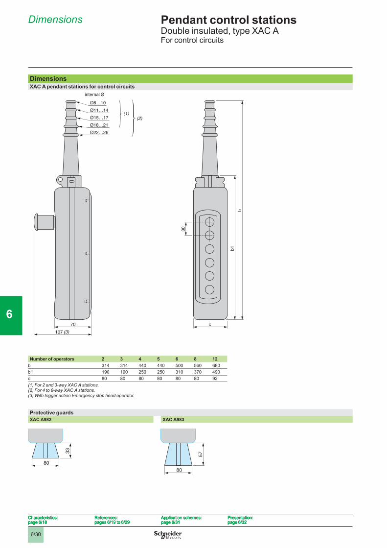
6/30
Pendant control stations 6 Double insulated, type XAC AFor control circuits
Dimensions 6
DimensionsXAC A pendant stations for control circuits
internal Ø
Number of operators 2 3 4 5 6 8 12b 314 314 440 440 500 560 680b1 190 190 250 250 310 370 490c 80 80 80 80 80 80 92(1) For 2 and 3-way XAC A stations.(2) For 4 to 8-way XAC A stations.(3) With trigger action Emergency stop head operator.
Protective guardsXAC A982 XAC A983
80
33
80
33
80
57
80
57
Characteristics:page 6/18
References:pages 6/19 to 6/29
Application schemes:page 6/31
Presentation:page 6/32
Characteristics:page 6/18
References:pages 6/19 to 6/29
Application schemes:page 6/31
Presentation:page 6/32
Characteristics:page 6/18
References:pages 6/19 to 6/29
Application schemes:page 6/31
Presentation:page 6/32
Characteristics:page 6/18
References:pages 6/19 to 6/29
Application schemes:page 6/31
Presentation:page 6/32
1
2
3
4
5
6
7
8
9
10
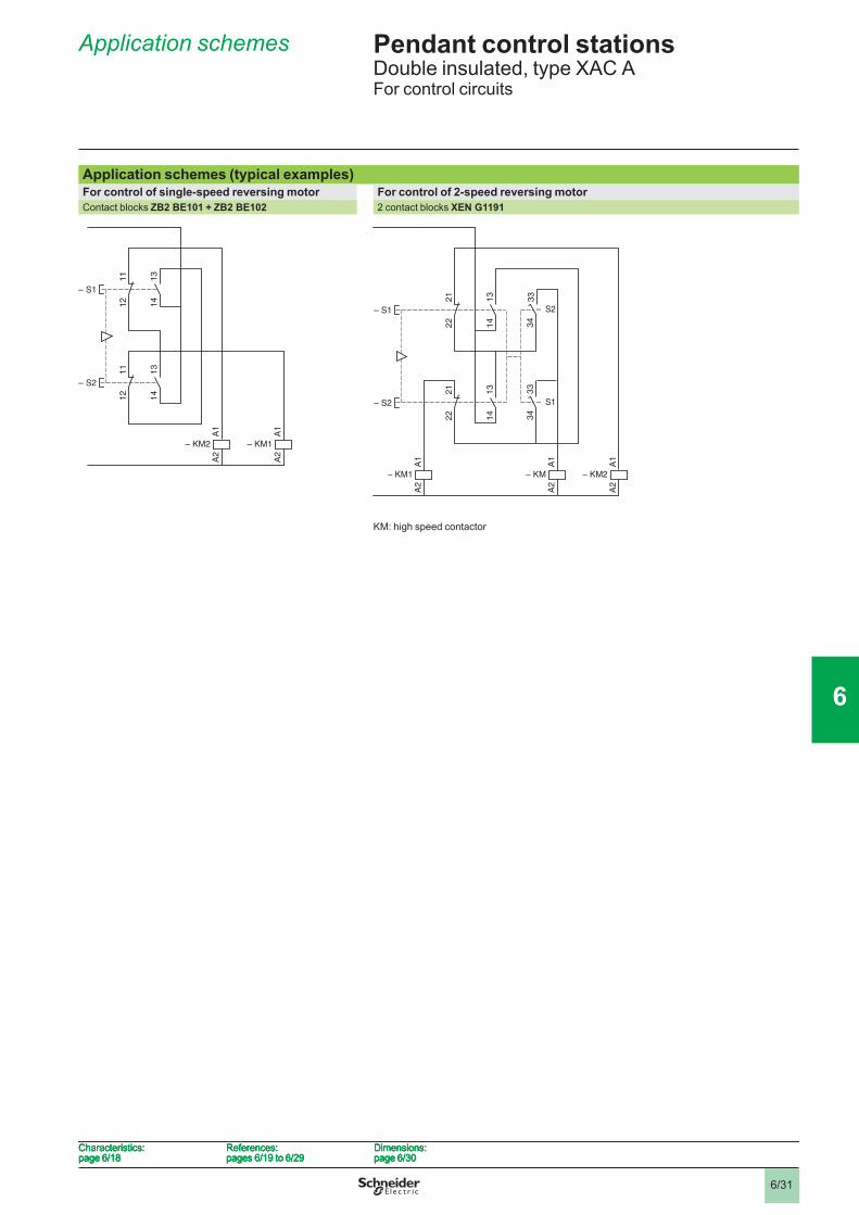
6/31
Pendant control stations 6 Double insulated, type XAC AFor control circuits
Application schemes 6
Application schemes (typical examples)For control of single-speed reversing motor For control of 2-speed reversing motorContact blocks ZB2 BE101 + ZB2 BE102 2 contact blocks XEN G1191
KM: high speed contactor
13
14
11
12
13
14
11
12
A1
A2
– KM2
– S1
A1
A2
– KM1
– S2
13
14
11
12
13
14
11
12
A1
A2
– KM2
– S1
A1
A2
– KM1
– S2
34
33
34
13
33
14
21
22
13
14
21
22
A1
A2
– KM2
A1
A2
– KM
– S1
A1
A2
– KM1
– S2 – S1
– S2
34
33
34
13
33
14
21
22
13
14
21
22
A1
A2
– KM2
A1
A2
– KM
– S1
A1
A2
– KM1
– S2 – S1
– S2
Characteristics:page 6/18
References:pages 6/19 to 6/29
Dimensions:page 6/30
Characteristics:page 6/18
References:pages 6/19 to 6/29
Dimensions:page 6/30
Characteristics:page 6/18
References:pages 6/19 to 6/29
Dimensions:page 6/30
Characteristics:page 6/18
References:pages 6/19 to 6/29
Dimensions:page 6/30
1
2
3
4
5
6
7
8
9
10
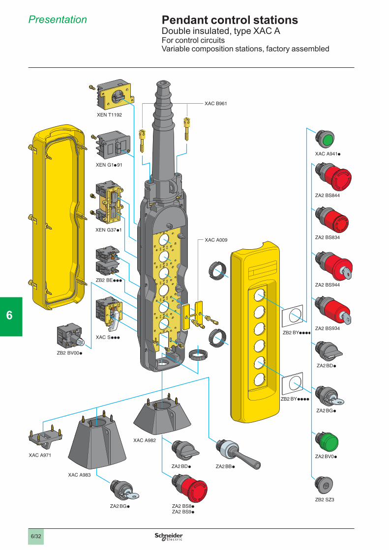
6/32
Pendant control stations 6 Double insulated, type XAC AFor control circuitsVariable composition stations, factory assembled
Presentation 6
1
2
3
4
5
6
7
8
9
10
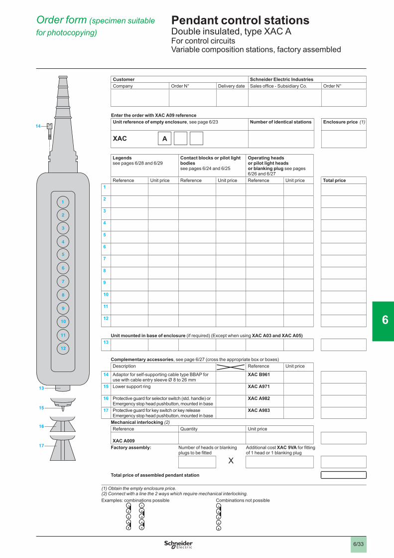
6/33
Pendant control stations 6 Double insulated, type XAC AFor control circuitsVariable composition stations, factory assembled
A
Order form (specimen suitable for photocopying) 6
Customer Schneider Electric IndustriesCompany Order N° Delivery date Sales offi ce - Subsidiary Co. Order N°
Enter the order with XAC A09 referenceUnit reference of empty enclosure, see page 6/23 Number of identical stations Enclosure price (1)
XAC
Legendssee pages 6/28 and 6/29
Contact blocks or pilot light bodiessee pages 6/24 and 6/25
Operating heads or pilot light heads or blanking plug see pages 6/26 and 6/27
Reference Unit price Reference Unit price Reference Unit price Total price1
2
3
4
5
6
7
8
9
10
11
12
Unit mounted in base of enclosure (if required) (Except when using XAC A03 and XAC A05)13
Complementary accessories, see page 6/27 (cross the appropriate box or boxes)Description Reference Unit price
14 Adaptor for self-supporting cable type BBAP for use with cable entry sleeve Ø 8 to 26 mm
XAC B961
15 Lower support ring XAC A971
16 Protective guard for selector switch (std. handle) or Emergency stop head pushbutton, mounted in base
XAC A982
17 Protective guard for key switch or key release Emergency stop head pushbutton, mounted in base
XAC A983
Mechanical interlocking (2)Reference Quantity Unit price
XAC A009Factory assembly: Number of heads or blanking
plugs to be fi ttedAdditional cost XAC 9VA for fi tting of 1 head or 1 blanking plug
X
Total price of assembled pendant station
(1) Obtain the empty enclosure price.(2) Connect with a line the 2 ways which require mechanical interlocking.Examples: combinations possible Combinations not possible
17
16
15
13
14
1
2
3
4
5
6
7
8
9
10
12
11
17
16
15
13
14
1
2
3
4
5
6
7
8
9
10
12
11
11
2
3
4
5
2
3
4
5
11
2
3
4
5
2
3
4
5
1
2
3
4
5
1
2
3
4
5
1
2
3
4
5
6
7
8
9
10
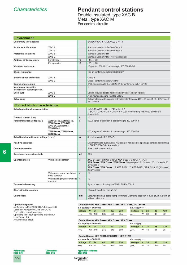
6/34
Pendant control stations 6 Double insulated, type XAC B Metal, type XAC MFor control circuits
Characteristics 6
EnvironmentConformity to standards EN/IEC 60947-5-1, CSA C22-2 n° 14
Product certifi cations XAC B Standard version: CSA 300 V type 4XAC M Standard version: CSA 300 V type 4
Protective treatment XAC B Standard version: “TH”XAC M Standard version: “TC”, (“TH” on request)
Ambient air temperature For storage °C - 40…+ 70For operation °C - 25…+ 70
Vibration resistance 15 gn (10…500 Hz) conforming to IEC 60068-2-6
Shock resistance 100 gn conforming to IEC 60068-2-27
Electric shock protection XAC B Class IIXAC M Class I conforming to IEC 61140
Degree of protection IP 65 conforming to IEC 60529; IK 08 conforming to EN 50102Mechanical durability(in millions of operating cycles)
1
Enclosure XAC B Double insulated glass-reinforced polyester (colour: yellow)XAC M Aluminium enclosure. Painted yellow
Cable entry Rubber sleeve with stepped entry diameter for cable Ø 7…13 mm, Ø 10…22 mm or Ø 22…35 mm
Contact block characteristicsRated operational characteristics a AC-15: A300 or Ue = 240 V, le = 3 A
c DC-13: Q300 or Ue = 250 V, le = 0.27 A conforming to EN/IEC 60947-5-1 Appendix A
Thermal current (lthe) A 10Rated insulation voltage (Ui) XEN Cpppp, XEN D3ppp,
XEN D4ppp, XES B2011, XAC S4, XES D1181, XES D1281
V 500, degree of pollution 3, conforming to IEC 60947-1
XEN Bpppp, XEN D1ppp, XEN D2ppp
400, degree of pollution 3, conforming to IEC 60947-1
Rated impulse withstand voltage (U imp) kV 6, conforming to IEC 60947-1
Positive operation Mushroom head pushbutton: N/C contact with positive opening operation conforming to EN/IEC 60947-5-1 Appendix K
Contact operation Slow break or snap action
Resistance across terminals MΩ y 25
Operating force With booted operator N XAC S4ppp: 10 (N/O), 8 (N/C); XEN Cpppp: 6 (N/O), 4 (N/C);XEN Bpppp, XEN D1ppp, XEN D2ppp: Single-speed: 9; 2-speed: 20 (1st speed), 30 (2nd speed); XEN D3ppp, XEN D4ppp: 25; XES B2011: 7; XES D1181, XES D128: 15 (1st speed), 25 (2nd speed)
With spring return mushroom head operator
N 10
With latching mushroom head operator
N 40
Terminal referencing By numbers conforming to CENELEC EN 50013
Short-circuit protection 10 A cartridge fuse type gG (gl)
Connection mm2 Screw and captive cable clamp terminals. Clamping capacity: 1 x 2.5 or 2 x 1.5 with or without cable end
Operational powerconforming to EN/IEC 60947-5-1 Appendix CUtilisation categories AC-15 and DC-13For 1 million operating cyclesOperating rate: 3600 operating cycles/hourLoad factor: 0.5o Inductive circuit
Contact blocks XEN Cpppp, XEN D3ppp, XEN D4ppp, XAC S4ppp
a.c. supply a 50/60 Hz d.c. supply cVoltage V 24 48 127 230 Voltage V 24 48 120
o VA 140 385 525 455 o W 60 45 42
Contact blocks XEN Bpppp, XEN D1ppp, XEN D2ppp
a.c. supply a 50/60 Hz d.c. supply cVoltage V 24 48 127 230 Voltage V 24 48 120
o VA 140 210 640 680 o W 48 31 35
Contact blocks XES B2011, XES D1181, XES D1281a.c. supply a 50/60 Hz d.c. supply cVoltage V 24 48 127 230 Voltage V 24 48 120
o VA 50 100 450 750 o W 140 140 95
References:page 6/35
Dimensions:page 6/55
Application schemes:page 6/56
References:page 6/35
Dimensions:page 6/55
Application schemes:page 6/56
References:page 6/35
Dimensions:page 6/55
Application schemes:page 6/56
References:page 6/35
Dimensions:page 6/55
Application schemes:page 6/56
1
2
3
4
5
6
7
8
9
10
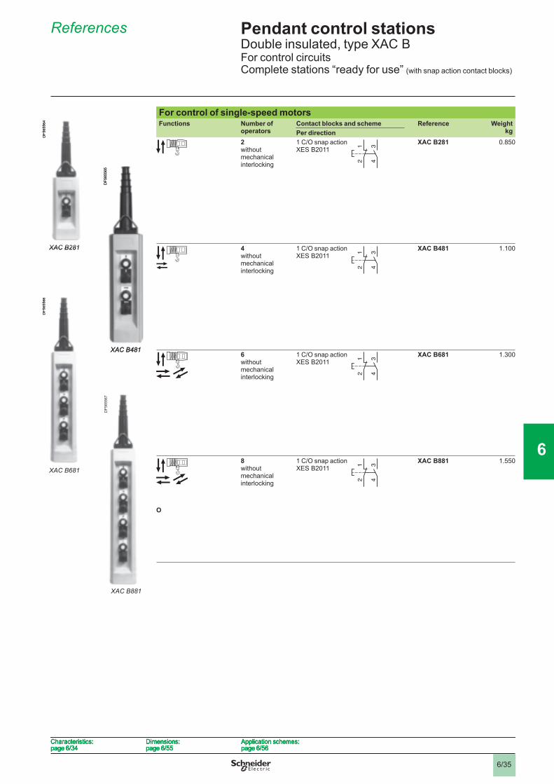
6/35
Pendant control stations 6 Double insulated, type XAC BFor control circuitsComplete stations “ready for use” (with snap action contact blocks)
References 6
For control of single-speed motorsFunctions Number of
operatorsContact blocks and scheme Reference Weight
kgPer direction2without mechanical interlocking
1 C/O snap action XES B2011
XAC B281 0.850
4without mechanical interlocking
1 C/O snap action XES B2011
XAC B481 1.100
6without mechanical interlocking
1 C/O snap action XES B2011
XAC B681 1.300
I
O
8without mechanical interlocking
1 C/O snap action XES B2011
XAC B881 1.550
342
1 342
1
XAC B281
DF5
6556
4
XAC B281
DF5
6556
4
342
1 342
1
XAC B481
DF5
6556
5
XAC B481
DF5
6556
5
342
1 342
1
XAC B681
DF5
6556
6
XAC B681
DF5
6556
6
342
1 342
1
XAC B881
DF5
6556
7
XAC B881
DF5
6556
7
Characteristics:page 6/34
Dimensions:page 6/55
Application schemes:page 6/56
Characteristics:page 6/34
Dimensions:page 6/55
Application schemes:page 6/56
Characteristics:page 6/34
Dimensions:page 6/55
Application schemes:page 6/56
Characteristics:page 6/34
Dimensions:page 6/55
Application schemes:page 6/56
1
2
3
4
5
6
7
8
9
10
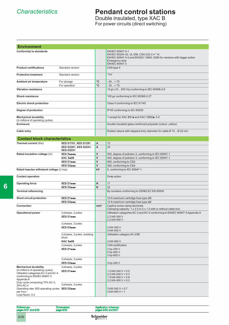
6/36
Pendant control stations 6 Double insulated, type XAC BFor power circuits (direct switching)
Characteristics 6
EnvironmentConformity to standards EN/IEC 60947-5-1
EN/IEC 60204-32, UL 508, CSA C22-2 n° 14EN/IEC 60947-5-5 and EN/ISO 13850: 2006 for versions with trigger action Emergency stopEN/IEC 60947-3
Product certifi cations Standard version CSA type 4
Protective treatment Standard version “TH”
Ambient air temperature For storage °C - 40…+ 70For operation °C - 25…+ 70
Vibration resistance 15 gn (10…500 Hz) conforming to IEC 60068-2-6
Shock resistance 100 gn conforming to IEC 60068-2-27
Electric shock protection Class II conforming to IEC 61140
Degree of protection IP 65 conforming to IEC 60529
Mechanical durability(in millions of operating cycles)
1 except for XAC B91p and XAC CB92p: 0.4
Enclosure Double insulated glass-reinforced polyester (colour: yellow)
Cable entry Rubber sleeve with stepped entry diameter for cable Ø 10…Ø 22 mm
Contact block characteristicsThermal current (lthe) XES D1191, XES D1291 A 12
XES D2201, XES D2241, XES D2251
A 20
Rated insulation voltage (Ui) XES Dpppp V 500, degree of pollution 3, conforming to IEC 60947-1XAC Sp99 V 400, degree of pollution 3, conforming to IEC 60947-1XES D1ppp V 600, conforming to CSAXES D2ppp V 300, conforming to CSA
Rated impulse withstand voltage (U imp) kV 6, conforming to IEC 60947-1
Contact operation Snap action
Operating force XES D1ppp N 17XES D2ppp N 32
Terminal referencing By numbers conforming to CENELEC EN 50005
Short-circuit protection XES D1ppp 10 A maximum cartridge fuse type aMXES D2ppp 12 A maximum cartridge fuse type aM
Connection mm2 Captive screw clamp terminalsClamping capacity: 1 x 2.5 or 2 x 1.5 with or without cable end
Operational power 3 phases, 2 poles Utilisation categories AC-3 and AC-4 conforming to EN/IEC 60947-3 Appendix AXES D1ppp 2.2 kW-240 V
2.2 kW-400 V3 phases, 3 polesXES D2ppp 3 kW-240 V
3 kW-400 V3 phases, 3 poles, isolating block
Utilisation category AC-23B
XAC Sp99 3 kW-400 V3 phases, 2 poles CSA certifi cationXES D1ppp 2 hp-240 V
5 hp-400 V3 hp-600 V
3 phases, 3 polesXES D2ppp 3 hp-240 V
Mechanical durability(in millions of operating cycles)Utilisation categories AC-3 and AC-4conforming to EN/IEC 60947-3 Appendix ADuty cycle comprising 75% AC-3, 25% AC-4Operating rate: 600 operating cycles per hourLoad factor: 0.4
3 phases, 2 polesXES D1ppp 1.5 kW-240 V = 0.5
2.2 kW-240 V = 0.31.5 kW-400 V = 0.82.2 kW-400 V = 0.3
3 phases, 3 polesXES D2ppp 3 kW-240 V = 0.7
3 kW-400 V = 1
References:pages 6/37 and 6/38
Dimensions:page 6/55
Application schemes:pages 6/56 and 6/57
References:pages 6/37 and 6/38
Dimensions:page 6/55
Application schemes:pages 6/56 and 6/57
References:pages 6/37 and 6/38
Dimensions:page 6/55
Application schemes:pages 6/56 and 6/57
References:pages 6/37 and 6/38
Dimensions:page 6/55
Application schemes:pages 6/56 and 6/57
1
2
3
4
5
6
7
8
9
10
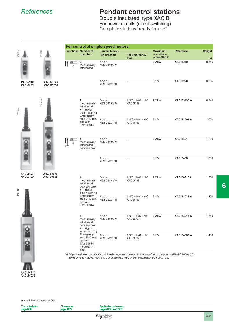
6/37
Pendant control stations 6 Double insulated, type XAC BFor power circuits (direct switching)Complete stations “ready for use”
References 6
For control of single-speed motorsFunctions Number of
operatorsContact blocks Maximum
operational power/400 V
Reference WeightPer direction For Emergency
stop kg2mechanically interlocked
2-poleXES D1191(1)
– 2.2 kW XAC B219 0.355
3-poleXES D2201(1)
– 3 kW XAC B220 0.355
2 mechanically interlocked + 1 trigger action latching Emergency stop Ø 40 mm operator ZA2 BS844
2-poleXES D1191(1)
1 N/C + N/C + N/CXAC S499
2.2 kW XAC B3195 r 0.940
3-poleXES D2201(1)
1 N/C + N/C + N/CXAC S499
3 kW XAC B3205 r 1.000
4mechanically interlocked between pairs
2-poleXES D1191(1)
– 2.2 kW XAC B491 1.200
3-poleXES D2201(1)
– 3 kW XAC B493 1.330
4 mechanically interlocked between pairs + 1 trigger action latching Emergency stop Ø 40 mm operator ZA2 BS844
2-poleXES D1191(1)
1 N/C + N/C + N/CXAC S499
2.2 kW XAC B4916 r 1.260
3-poleXES D2201(1)
1 N/C + N/C + N/CXAC S499
3 kW XAC B4936 r 1.390
4 mechanically interlocked between pairs + 1 trigger action latching Emergency stop Ø 40 mm operator ZA2 BS844 mounted in base
2-poleXES D1191(1)
1 N/C + N/C + N/CXAC S3991
2.2 kW XAC B4915 r 1.350
3-poleXES D2201(1)
1 N/C + N/C + N/CXAC S3991
3 kW XAC B4935 r 1.480
(1) Trigger action mechanically latching Emergency stop pushbuttons conform to standards EN/IEC 60204-32, EN/ISO 13850: 2006, Machinery directive 98/37/EC and standard EN/IEC 60947-5-5.
XAC B219XAC B220
DF5
6556
8
XAC B219XAC B220
DF5
6556
8
XAC B3195XAC B3205
DF5
6556
9
XAC B3195XAC B3205
DF5
6556
9
XAC B491XAC B493
DF5
6557
0
XAC B491XAC B493
DF5
6557
0
XAC B4916XAC B4936
DF5
6557
1
XAC B4916XAC B4936
DF5
6557
1
XAC B4915XAC B4935
DF5
6557
2
XAC B4915XAC B4935
DF5
6557
2
Characteristics:page 6/36
Dimensions:page 6/55
Application schemes:pages 6/56 and 6/57
Characteristics:page 6/36
Dimensions:page 6/55
Application schemes:pages 6/56 and 6/57
Characteristics:page 6/36
Dimensions:page 6/55
Application schemes:pages 6/56 and 6/57
Characteristics:page 6/36
Dimensions:page 6/55
Application schemes:pages 6/56 and 6/57
r Available 3rd quarter of 2011
1
2
3
4
5
6
7
8
9
10
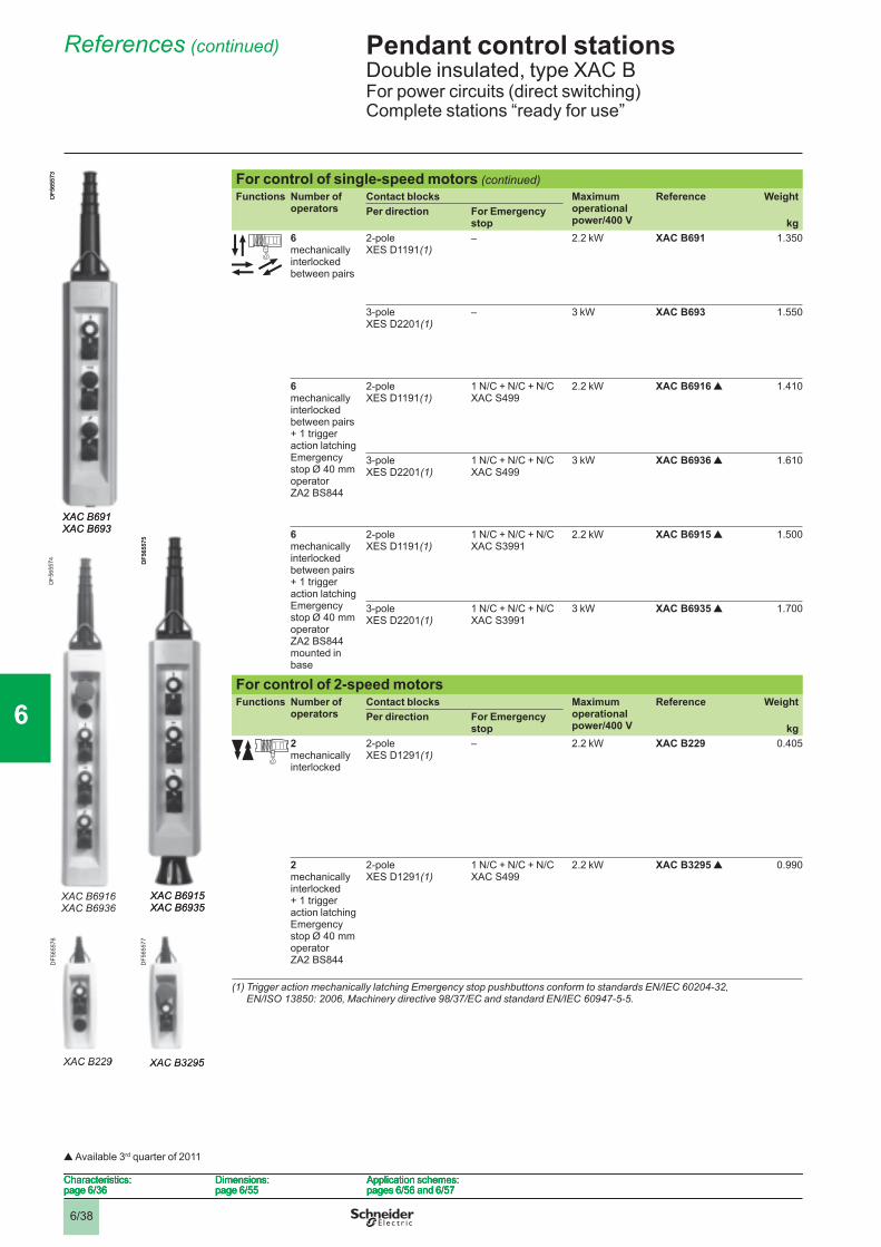
6/38
Pendant control stations 6 Double insulated, type XAC BFor power circuits (direct switching)Complete stations “ready for use”
References (continued) 6
For control of single-speed motors (continued)Functions Number of
operatorsContact blocks Maximum
operational power/400 V
Reference WeightPer direction For Emergency
stop kg6mechanically interlocked between pairs
2-poleXES D1191(1)
– 2.2 kW XAC B691 1.350
3-poleXES D2201(1)
– 3 kW XAC B693 1.550
6 mechanically interlocked between pairs + 1 trigger action latching Emergency stop Ø 40 mm operator ZA2 BS844
2-poleXES D1191(1)
1 N/C + N/C + N/CXAC S499
2.2 kW XAC B6916 r 1.410
3-poleXES D2201(1)
1 N/C + N/C + N/CXAC S499
3 kW XAC B6936 r 1.610
6 mechanically interlocked between pairs + 1 trigger action latching Emergency stop Ø 40 mm operator ZA2 BS844 mounted in base
2-poleXES D1191(1)
1 N/C + N/C + N/CXAC S3991
2.2 kW XAC B6915 r 1.500
3-poleXES D2201(1)
1 N/C + N/C + N/CXAC S3991
3 kW XAC B6935 r 1.700
For control of 2-speed motorsFunctions Number of
operatorsContact blocks Maximum
operational power/400 V
Reference WeightPer direction For Emergency
stop kg2mechanically interlocked
2-poleXES D1291(1)
– 2.2 kW XAC B229 0.405
2 mechanically interlocked + 1 trigger action latching Emergency stop Ø 40 mm operator ZA2 BS844
2-poleXES D1291(1)
1 N/C + N/C + N/CXAC S499
2.2 kW XAC B3295 r 0.990
(1) Trigger action mechanically latching Emergency stop pushbuttons conform to standards EN/IEC 60204-32, EN/ISO 13850: 2006, Machinery directive 98/37/EC and standard EN/IEC 60947-5-5.
XAC B691XAC B693
DF5
6557
3
XAC B691XAC B693
DF5
6557
3
XAC B6916XAC B6936
DF5
6557
4
XAC B6916XAC B6936
DF5
6557
4
XAC B6915XAC B6935
DF5
6557
5
XAC B6915XAC B6935
DF5
6557
5
XAC B229
DF5
6557
6
XAC B229
DF5
6557
6
XAC B3295
DF5
6557
7
XAC B3295
DF5
6557
7
Characteristics:page 6/36
Dimensions:page 6/55
Application schemes:pages 6/56 and 6/57
Characteristics:page 6/36
Dimensions:page 6/55
Application schemes:pages 6/56 and 6/57
Characteristics:page 6/36
Dimensions:page 6/55
Application schemes:pages 6/56 and 6/57
Characteristics:page 6/36
Dimensions:page 6/55
Application schemes:pages 6/56 and 6/57
r Available 3rd quarter of 2011
1
2
3
4
5
6
7
8
9
10
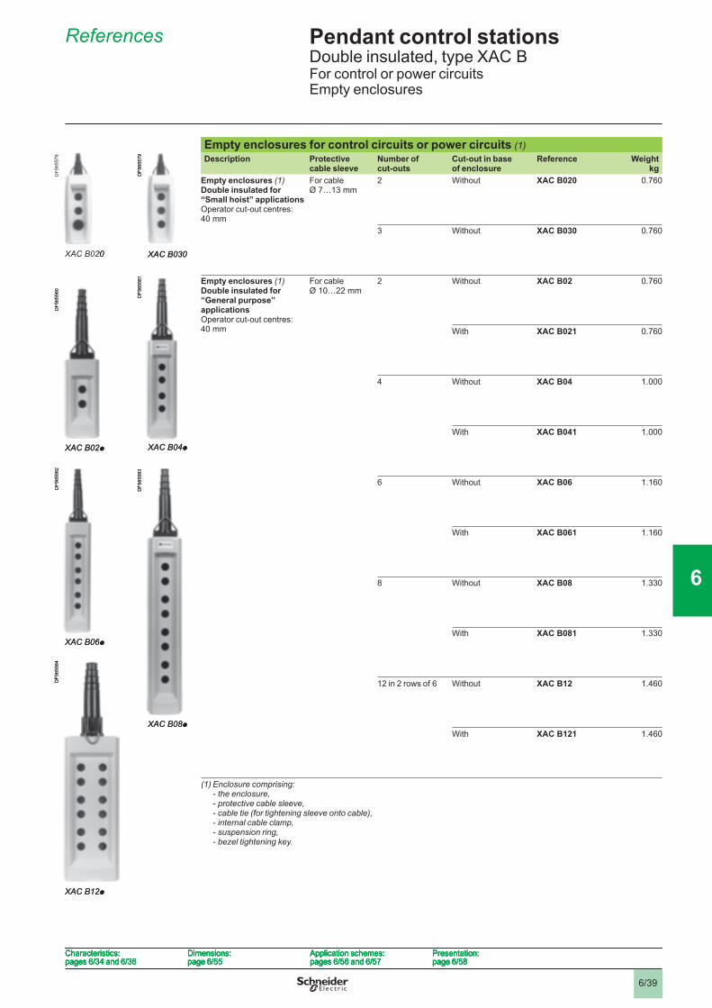
6/39
Pendant control stations 6 Double insulated, type XAC BFor control or power circuitsEmpty enclosures
References 6
Empty enclosures for control circuits or power circuits (1)Description Protective
cable sleeveNumber of cut-outs
Cut-out in base of enclosure
Reference Weightkg
Empty enclosures (1) Double insulated for “Small hoist” applications Operator cut-out centres: 40 mm
For cable Ø 7…13 mm
2 Without XAC B020 0.760
3 Without XAC B030 0.760
Empty enclosures (1) Double insulated for “General purpose” applications Operator cut-out centres: 40 mm
For cable Ø 10…22 mm
2 Without XAC B02 0.760
With XAC B021 0.760
4 Without XAC B04 1.000
With XAC B041 1.000
6 Without XAC B06 1.160
With XAC B061 1.160
8 Without XAC B08 1.330
With XAC B081 1.330
12 in 2 rows of 6 Without XAC B12 1.460
With XAC B121 1.460
(1) Enclosure comprising:- the enclosure,- protective cable sleeve,- cable tie (for tightening sleeve onto cable),- internal cable clamp,- suspension ring,- bezel tightening key.
XAC B020
DF5
6557
8
XAC B020
DF5
6557
8
XAC B030
DF5
6557
9
XAC B030
DF5
6557
9
XAC B02p
DF5
6558
0
XAC B02p
DF5
6558
0
XAC B04p
DF5
6558
1
XAC B04p
DF5
6558
1
XAC B06p
DF5
6558
2
XAC B06p
DF5
6558
2
XAC B08p
DF5
6558
3
XAC B08p
DF5
6558
3
XAC B12p
DF5
6558
4
XAC B12p
DF5
6558
4
Characteristics:pages 6/34 and 6/36
Dimensions:page 6/55
Application schemes:pages 6/56 and 6/57
Presentation:page 6/58
Characteristics:pages 6/34 and 6/36
Dimensions:page 6/55
Application schemes:pages 6/56 and 6/57
Presentation:page 6/58
Characteristics:pages 6/34 and 6/36
Dimensions:page 6/55
Application schemes:pages 6/56 and 6/57
Presentation:page 6/58
Characteristics:pages 6/34 and 6/36
Dimensions:page 6/55
Application schemes:pages 6/56 and 6/57
Presentation:page 6/58
1
2
3
4
5
6
7
8
9
10
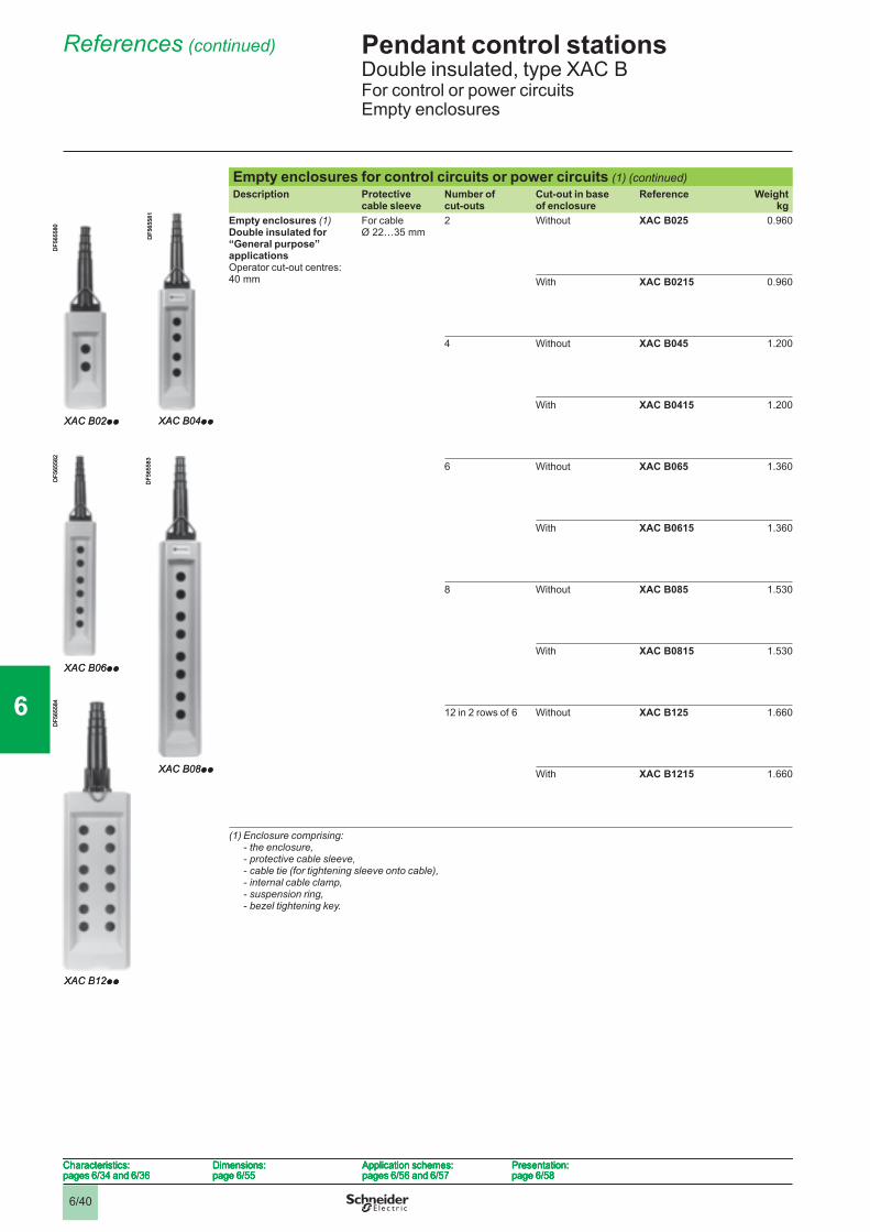
6/40
Pendant control stations 6 Double insulated, type XAC BFor control or power circuitsEmpty enclosures
References (continued) 6
Empty enclosures for control circuits or power circuits (1) (continued)Description Protective
cable sleeveNumber of cut-outs
Cut-out in base of enclosure
Reference Weightkg
Empty enclosures (1) Double insulated for “General purpose” applications Operator cut-out centres: 40 mm
For cable Ø 22…35 mm
2 Without XAC B025 0.960
With XAC B0215 0.960
4 Without XAC B045 1.200
With XAC B0415 1.200
6 Without XAC B065 1.360
With XAC B0615 1.360
8 Without XAC B085 1.530
With XAC B0815 1.530
12 in 2 rows of 6 Without XAC B125 1.660
With XAC B1215 1.660
(1) Enclosure comprising:- the enclosure,- protective cable sleeve,- cable tie (for tightening sleeve onto cable),- internal cable clamp,- suspension ring,- bezel tightening key.
XAC B02pp
DF5
6558
0
XAC B02pp
DF5
6558
0
XAC B04pp
DF5
6558
1
XAC B04pp
DF5
6558
1
XAC B06pp
DF5
6558
2
XAC B06pp
DF5
6558
2
XAC B08pp
DF5
6558
3
XAC B08pp
DF5
6558
3
XAC B12pp
DF5
6558
4
XAC B12pp
DF5
6558
4
Characteristics:pages 6/34 and 6/36
Dimensions:page 6/55
Application schemes:pages 6/56 and 6/57
Presentation:page 6/58
Characteristics:pages 6/34 and 6/36
Dimensions:page 6/55
Application schemes:pages 6/56 and 6/57
Presentation:page 6/58
Characteristics:pages 6/34 and 6/36
Dimensions:page 6/55
Application schemes:pages 6/56 and 6/57
Presentation:page 6/58
Characteristics:pages 6/34 and 6/36
Dimensions:page 6/55
Application schemes:pages 6/56 and 6/57
Presentation:page 6/58
1
2
3
4
5
6
7
8
9
10
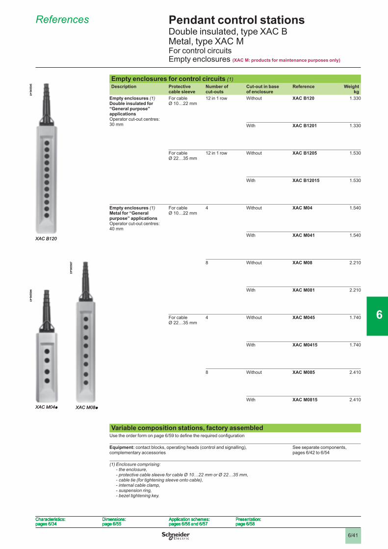
6/41
Pendant control stations 6 Double insulated, type XAC B Metal, type XAC MFor control circuitsEmpty enclosures (XAC M: products for maintenance purposes only)
References 6
Empty enclosures for control circuits (1)Description Protective
cable sleeveNumber of cut-outs
Cut-out in base of enclosure
Reference Weightkg
Empty enclosures (1) Double insulated for “General purpose” applications Operator cut-out centres: 30 mm
For cable Ø 10…22 mm
12 in 1 row Without XAC B120 1.330
With XAC B1201 1.330
For cable Ø 22…35 mm
12 in 1 row Without XAC B1205 1.530
With XAC B12015 1.530
Empty enclosures (1) Metal for “General purpose” applicationsOperator cut-out centres: 40 mm
For cable Ø 10…22 mm
4 Without XAC M04 1.540
With XAC M041 1.540
8 Without XAC M08 2.210
With XAC M081 2.210
For cable Ø 22…35 mm
4 Without XAC M045 1.740
With XAC M0415 1.740
8 Without XAC M085 2.410
With XAC M0815 2.410
Variable composition stations, factory assembledUse the order form on page 6/59 to defi ne the required confi guration
Equipment: contact blocks, operating heads (control and signalling), complementary accessories
See separate components, pages 6/42 to 6/54
(1) Enclosure comprising:- the enclosure,- protective cable sleeve for cable Ø 10…22 mm or Ø 22…35 mm,- cable tie (for tightening sleeve onto cable),- internal cable clamp,- suspension ring,- bezel tightening key.
XAC B120
DF5
6558
5
XAC B120
DF5
6558
5
XAC M04p
DF5
6558
6
XAC M04p
DF5
6558
6
XAC M08p
DF5
6558
7
XAC M08p
DF5
6558
7
Characteristics:pages 6/34
Dimensions:page 6/55
Application schemes:pages 6/56 and 6/57
Presentation:page 6/58
Characteristics:pages 6/34
Dimensions:page 6/55
Application schemes:pages 6/56 and 6/57
Presentation:page 6/58
Characteristics:pages 6/34
Dimensions:page 6/55
Application schemes:pages 6/56 and 6/57
Presentation:page 6/58
Characteristics:pages 6/34
Dimensions:page 6/55
Application schemes:pages 6/56 and 6/57
Presentation:page 6/58
1
2
3
4
5
6
7
8
9
10
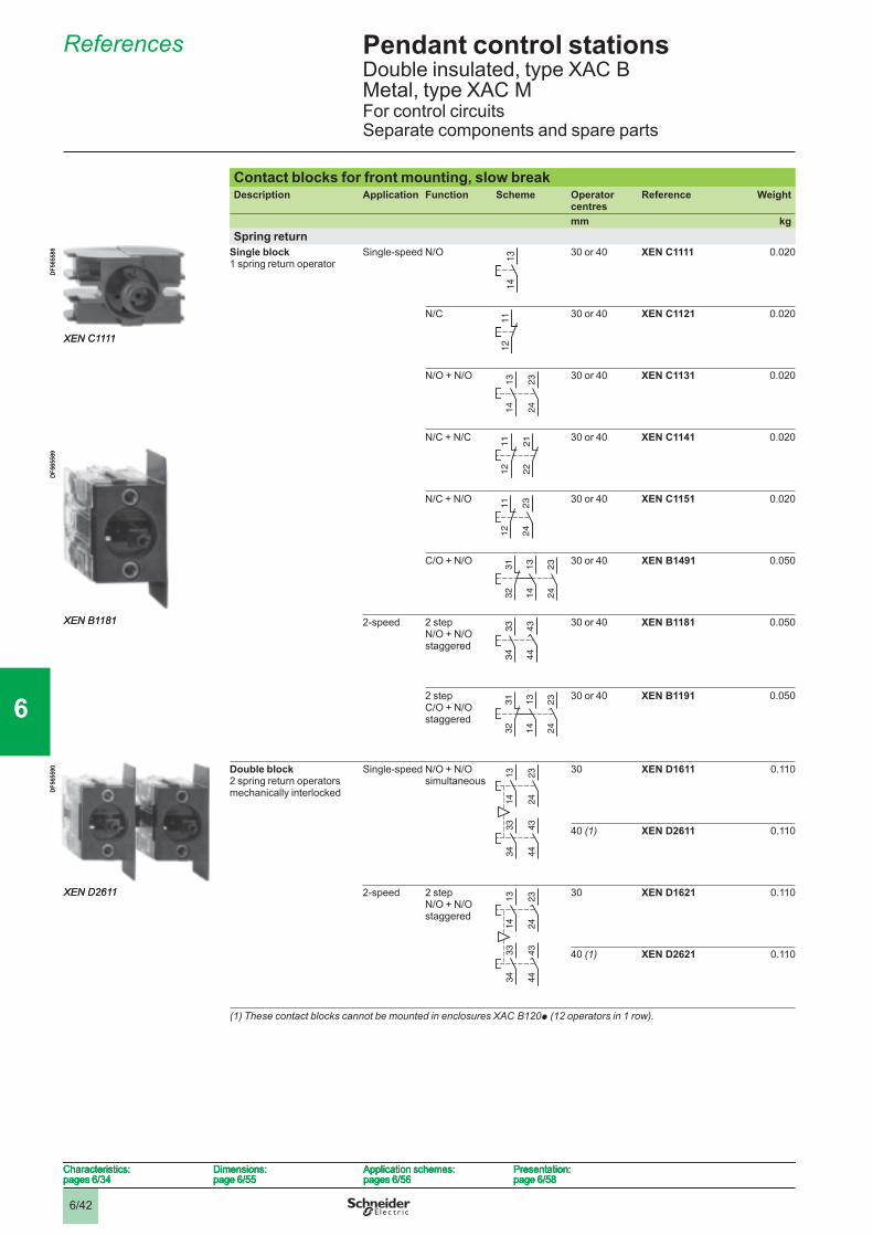
6/42
Pendant control stations 6 Double insulated, type XAC B Metal, type XAC MFor control circuitsSeparate components and spare parts
References 6
Contact blocks for front mounting, slow breakDescription Application Function Scheme Operator
centresReference Weight
mm kgSpring return
Single block1 spring return operator
Single-speed N/O 30 or 40 XEN C1111 0.020
N/C 30 or 40 XEN C1121 0.020
N/O + N/O 30 or 40 XEN C1131 0.020
N/C + N/C 30 or 40 XEN C1141 0.020
N/C + N/O 30 or 40 XEN C1151 0.020
C/O + N/O 30 or 40 XEN B1491 0.050
2-speed 2 step N/O + N/O staggered
30 or 40 XEN B1181 0.050
2 step C/O + N/O staggered
30 or 40 XEN B1191 0.050
Double block2 spring return operators mechanically interlocked
Single-speed N/O + N/Osimultaneous
30 XEN D1611 0.110
40 (1) XEN D2611 0.110
2-speed 2 step N/O + N/O staggered
30 XEN D1621 0.110
40 (1) XEN D2621 0.110
(1) These contact blocks cannot be mounted in enclosures XAC B120p (12 operators in 1 row).
13
14
13
14
XEN C1111
DF5
6558
8
XEN C1111
DF5
6558
8
11
12
11
12
13
14
23
24
13
14
23
24
11
12
21
22
11
12
21
22
23
24
11
12
23
24
11
12
13
14
32
31
23
24
13
14
32
31
23
24
43
44
34
33
43
44
34
33XEN B1181
DF5
6558
9
XEN B1181
DF5
6558
9
13
14
32
31
23
24
13
14
32
31
23
24
13
14
23
24
33
34
43
44
13
14
23
24
33
34
43
44
XEN D2611
DF5
6559
0
XEN D2611
DF5
6559
0
13
14
23
24
33
34
43
44
13
14
23
24
33
34
43
44
Characteristics:pages 6/34
Dimensions:page 6/55
Application schemes:pages 6/56
Presentation:page 6/58
Characteristics:pages 6/34
Dimensions:page 6/55
Application schemes:pages 6/56
Presentation:page 6/58
Characteristics:pages 6/34
Dimensions:page 6/55
Application schemes:pages 6/56
Presentation:page 6/58
Characteristics:pages 6/34
Dimensions:page 6/55
Application schemes:pages 6/56
Presentation:page 6/58
1
2
3
4
5
6
7
8
9
10
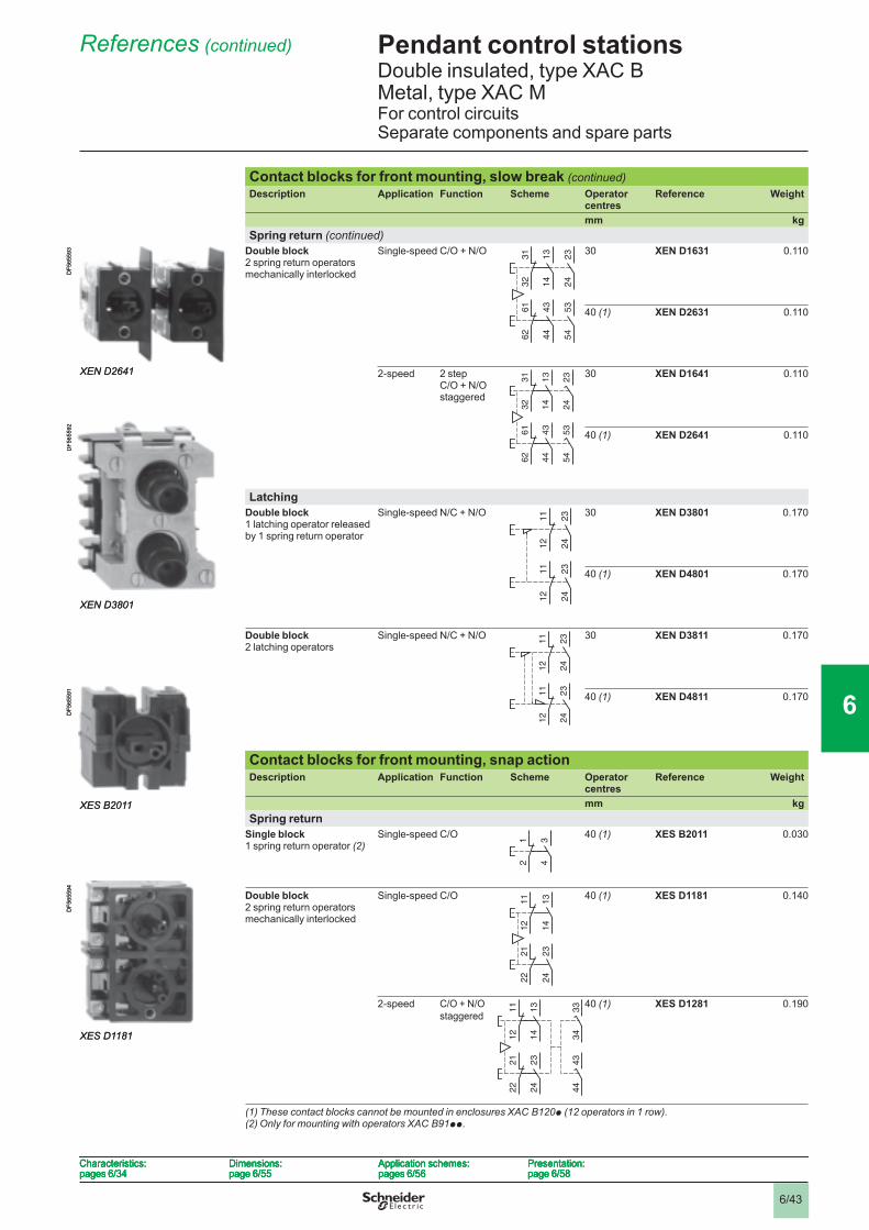
6/43
Pendant control stations 6 Double insulated, type XAC B Metal, type XAC MFor control circuitsSeparate components and spare parts
References (continued) 6
Contact blocks for front mounting, slow break (continued)Description Application Function Scheme Operator
centresReference Weight
mm kgSpring return (continued)
Double block2 spring return operators mechanically interlocked
Single-speed C/O + N/O 30 XEN D1631 0.110
40 (1) XEN D2631 0.110
2-speed 2 stepC/O + N/O staggered
30 XEN D1641 0.110
40 (1) XEN D2641 0.110
LatchingDouble block1 latching operator released by 1 spring return operator
Single-speed N/C + N/O 30 XEN D3801 0.170
40 (1) XEN D4801 0.170
Double block2 latching operators
Single-speed N/C + N/O 30 XEN D3811 0.170
40 (1) XEN D4811 0.170
Contact blocks for front mounting, snap actionDescription Application Function Scheme Operator
centresReference Weight
mm kgSpring return
Single block1 spring return operator (2)
Single-speed C/O 40 (1) XES B2011 0.030
Double block2 spring return operators mechanically interlocked
Single-speed C/O 40 (1) XES D1181 0.140
2-speed C/O + N/Ostaggered
40 (1) XES D1281 0.190
(1) These contact blocks cannot be mounted in enclosures XAC B120p (12 operators in 1 row).(2) Only for mounting with operators XAC B91pp.
13
14
32
31
23
24
43
44
62
61
53
54
13
14
32
31
23
24
43
44
62
61
53
54
13
14
32
31
23
24
43
44
62
61
53
54
13
14
32
31
23
24
43
44
62
61
53
54
XEN D2641
DF5
6559
3
XEN D2641
DF5
6559
3
23
24
12
11
23
24
12
11
23
24
12
11
23
24
12
11
XEN D3801
DF5
6559
2
XEN D3801
DF5
6559
2
23
24
12
11
23
24
12
11
23
24
12
11
23
24
12
11
342
1 342
1
XES B2011
DF5
6559
1
XES B2011
DF5
6559
1
13
14
11
12
23
24
21
22
13
14
11
12
23
24
21
22
XES D1181
DF5
6559
4
XES D1181
DF5
6559
4
13
14
12
11
33
34
23
24
22
21
43
44
13
14
12
11
33
34
23
24
22
21
43
44
Characteristics:pages 6/34
Dimensions:page 6/55
Application schemes:pages 6/56
Presentation:page 6/58
Characteristics:pages 6/34
Dimensions:page 6/55
Application schemes:pages 6/56
Presentation:page 6/58
Characteristics:pages 6/34
Dimensions:page 6/55
Application schemes:pages 6/56
Presentation:page 6/58
Characteristics:pages 6/34
Dimensions:page 6/55
Application schemes:pages 6/56
Presentation:page 6/58
1
2
3
4
5
6
7
8
9
10
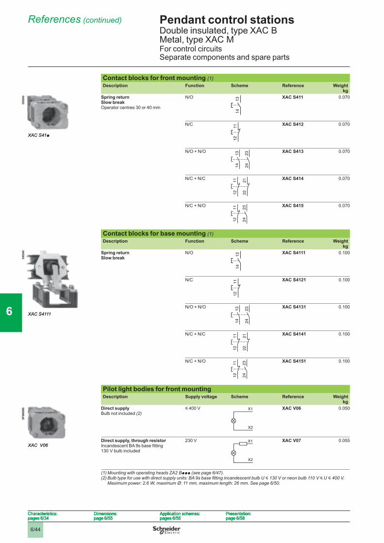
6/44
Pendant control stations 6 Double insulated, type XAC B Metal, type XAC MFor control circuitsSeparate components and spare parts
References (continued) 6
Contact blocks for front mounting (1)Description Function Scheme Reference Weight
kgSpring returnSlow breakOperator centres 30 or 40 mm
N/O XAC S411 0.070
N/C XAC S412 0.070
N/O + N/O XAC S413 0.070
N/C + N/C XAC S414 0.070
N/C + N/O XAC S415 0.070
Contact blocks for base mounting (1)Description Function Scheme Reference Weight
kgSpring returnSlow break
N/O XAC S4111 0.100
N/C XAC S4121 0.100
N/O + N/O XAC S4131 0.100
N/C + N/C XAC S4141 0.100
N/C + N/O XAC S4151 0.100
Pilot light bodies for front mountingDescription Supply voltage Scheme Reference Weight
kgDirect supplyBulb not included (2)
y 400 V XAC V06 0.050
Direct supply, through resistorIncandescent BA 9s base fi tting130 V bulb included
230 V XAC V07 0.055
(1) Mounting with operating heads ZA2 Bppp (see page 6/47 ).(2) Bulb type for use with direct supply units: BA 9s base fi tting incandescent bulb U y 130 V or neon bulb 110 V y U y 400 V.
Maximum power: 2.6 W, maximum Ø: 11 mm, maximum length: 26 mm. See page 6/50 .
13
14
13
14
XAC S41p
5302
40
XAC S41p
5302
40
11
12
11
12
13
14
23
24
13
14
23
24
11
12
21
22
11
12
21
22
23
24
11
12
23
24
11
12
13
14
13
14
XAC S4111
5302
40
XAC S4111
5302
40
11
12
11
12
13
14
23
24
13
14
23
24
11
12
21
22
11
12
21
22
23
24
11
12
23
24
11
12
X1
X2
X1
X2
XAC V06
DF5
6559
5
XAC V06
DF5
6559
5
X1
X2
X1
X2
Characteristics:pages 6/34
Dimensions:page 6/55
Application schemes:pages 6/56
Presentation:page 6/58
Characteristics:pages 6/34
Dimensions:page 6/55
Application schemes:pages 6/56
Presentation:page 6/58
Characteristics:pages 6/34
Dimensions:page 6/55
Application schemes:pages 6/56
Presentation:page 6/58
Characteristics:pages 6/34
Dimensions:page 6/55
Application schemes:pages 6/56
Presentation:page 6/58
1
2
3
4
5
6
7
8
9
10
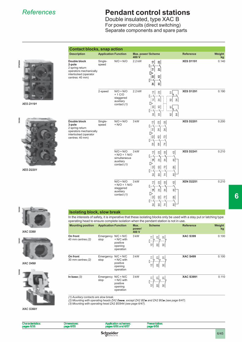
6/45
Pendant control stations 6 Double insulated, type XAC BFor power circuits (direct switching)Separate components and spare parts
References 6
Contact blocks, snap actionDescription Application Function Max. power/
400 VScheme Reference Weight
kgDouble block2-pole2 spring return operators mechanically interlocked (operator centres: 40 mm)
Single-speed
N/O + N/O 2.2 kW XES D1191 0.140
2-speed N/O + N/O + 1 C/O staggered auxiliary contact (1)
2.2 kW XES D1291 0.190
Double block 3-pole2 spring return operators mechanically interlocked (operator centres: 40 mm)
Single-speed
N/O + N/O + N/O
3 kW XES D2201 0.200
N/O + N/O + N/O + 1 N/O simultaneous auxiliary contact (1)
3 kW XES D2241 0.210
N/O + N/O + N/O + 1 N/O staggered auxiliary contact (1)
3 kW XEN D2251 0.210
Isolating block, slow breakIn the interests of safety, it is imperative that these isolating blocks only be used with a stay put or latching type operating head to ensure complete isolation when the pendant station is not in use.Mounting position Application Function Max.
power/400 V
Scheme Reference Weightkg
On front 40 mm centres (2)
Emergency stop
N/C + N/C + N/C with positive opening operation
3 kW XAC S399 0.100
On front 30 mm centres (2)
Emergency stop
N/C + N/C + N/C with positive opening operation
3 kW XAC S499 0.100
In base (3) Emergency stop
N/C + N/C + N/C with positive opening operation
3 kW XAC S3991 0.110
(1) Auxiliary contacts are slow break.(2) Mounting with operating heads ZA2 Bppp, except ZA2 BDp and ZA2 BGp (see page 6/47 ).(3) Mounting with operating head ZA2 BS944 (see page 6/47 ).
13
14
23
24
33
34
43
44
13
14
23
24
33
34
43
44
13
14
23
24
33
34
43
44
13
14
23
24
33
34
43
44
XES D1191
DF5
6559
4
XES D1191
DF5
6559
4
23
24
14
13
51
54
43
44
34
33
61
64
52
62
23
24
14
13
51
54
43
44
34
33
61
64
52
62
13
14
23
24
53
54
63
64
33
34
73
74
13
14
23
24
53
54
63
64
33
34
73
74
XES D2201
5303
68
XES D2201
5303
68
23
14
13
14
53
54
24
63
64
33
34
73
74
43
44
84
44
23
14
13
14
53
54
24
63
64
33
34
73
74
43
44
84
44
23
14
13
14
53
54
24
63
64
33
34
73
74
43
44
84
44
23
14
13
14
53
54
24
63
64
33
34
73
74
43
44
84
44
11
12
21
22
31
32
11
12
21
22
31
32
XAC S399
5303
69
XAC S399
5303
69
11
12
21
22
31
32
11
12
21
22
31
32XAC S499
5303
91
XAC S499
5303
91
11
12
21
22
31
32
11
12
21
22
31
32
XAC S3991
5303
66
XAC S3991
5303
66
Characteristics:pages 6/36
Dimensions:page 6/55
Application schemes:pages 6/56 and 6/57
Presentation:page 6/58
Characteristics:pages 6/36
Dimensions:page 6/55
Application schemes:pages 6/56 and 6/57
Presentation:page 6/58
Characteristics:pages 6/36
Dimensions:page 6/55
Application schemes:pages 6/56 and 6/57
Presentation:page 6/58
Characteristics:pages 6/36
Dimensions:page 6/55
Application schemes:pages 6/56 and 6/57
Presentation:page 6/58
1
2
3
4
5
6
7
8
9
10
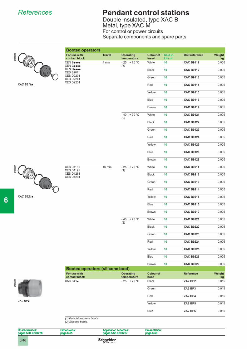
6/46
Pendant control stations 6 Double insulated, type XAC B Metal, type XAC MFor control or power circuitsSeparate components and spare parts
References 6
Booted operators For use with contact block
Travel Operating temperature
Colour of insert
Sold in lots of
Unit reference Weightkg
XEN BppppXEN CppppXEN DppppXES B2011XES D2201XES D2241XES D2251
4 mm - 25…+ 70 °C (1)
White 10 XAC B9111 0.005
Black 10 XAC B9112 0.005
Green 10 XAC B9113 0.005
Red 10 XAC B9114 0.005
Yellow 10 XAC B9115 0.005
Blue 10 XAC B9116 0.005
Brown 10 XAC B9119 0.005
- 40…+ 70 °C (2)
White 10 XAC B9121 0.005
Black 10 XAC B9122 0.005
Green 10 XAC B9123 0.005
Red 10 XAC B9124 0.005
Yellow 10 XAC B9125 0.005
Blue 10 XAC B9126 0.005
Brown 10 XAC B9129 0.005
XES D1181XES D1191XES D1281XES D1291
16 mm - 25…+ 70 °C (1)
White 10 XAC B9211 0.005
Black 10 XAC B9212 0.005
Green 10 XAC B9213 0.005
Red 10 XAC B9214 0.005
Yellow 10 XAC B9215 0.005
Blue 10 XAC B9216 0.005
Brown 10 XAC B9219 0.005
- 40…+ 70 °C (2)
White 10 XAC B9221 0.005
Black 10 XAC B9222 0.005
Green 10 XAC B9223 0.005
Red 10 XAC B9224 0.005
Yellow 10 XAC B9225 0.005
Blue 10 XAC B9226 0.005
Brown 10 XAC B9229 0.005
Booted operators (silicone boot)For use with contact block
Operating temperature
Colour of boot
Reference Weightkg
XAC S41p - 25…+ 70 °C Black ZA2 BP2 0.015
Green ZA2 BP3 0.015
Red ZA2 BP4 0.015
Yellow ZA2 BP5 0.015
Blue ZA2 BP6 0.015
(1) Polychloroprene boots.(2) Silicone boots.
XAC B911p
DF5
6559
6
XAC B911p
DF5
6559
6
XAC B921p
DF5
6559
7
XAC B921p
DF5
6559
7
ZA2 BPp
DF5
6559
8
ZA2 BPp
DF5
6559
8
Characteristics:pages 6/34 and 6/36
Dimensions:page 6/55
Application schemes:pages 6/56 and 6/57
Presentation:page 6/58
Characteristics:pages 6/34 and 6/36
Dimensions:page 6/55
Application schemes:pages 6/56 and 6/57
Presentation:page 6/58
Characteristics:pages 6/34 and 6/36
Dimensions:page 6/55
Application schemes:pages 6/56 and 6/57
Presentation:page 6/58
Characteristics:pages 6/34 and 6/36
Dimensions:page 6/55
Application schemes:pages 6/56 and 6/57
Presentation:page 6/58
1
2
3
4
5
6
7
8
9
10
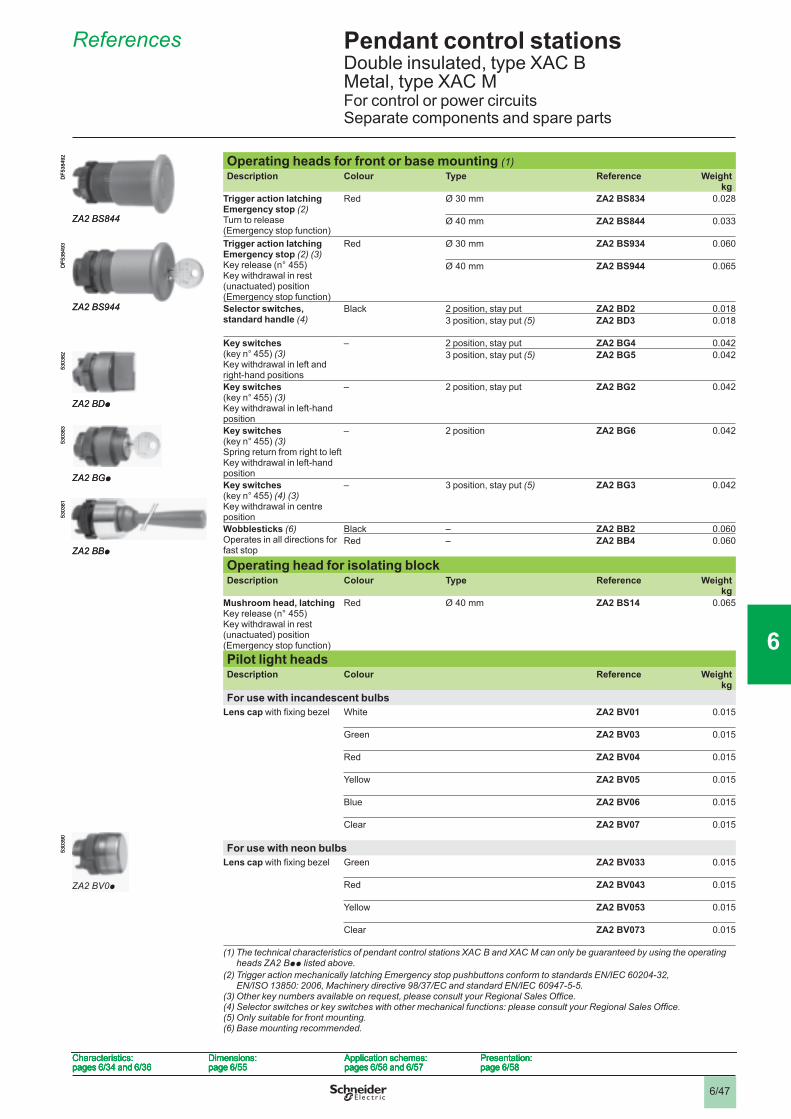
6/47
Pendant control stations 6 Double insulated, type XAC B Metal, type XAC MFor control or power circuitsSeparate components and spare parts
References 6
Operating heads for front or base mounting (1)Description Colour Type Reference Weight
kgTrigger action latching Emergency stop (2)Turn to release (Emergency stop function)
Red Ø 30 mm ZA2 BS834 0.028
Ø 40 mm ZA2 BS844 0.033
Trigger action latching Emergency stop (2) (3)Key release (n° 455) Key withdrawal in rest (unactuated) position (Emergency stop function)
Red Ø 30 mm ZA2 BS934 0.060
Ø 40 mm ZA2 BS944 0.065
Selector switches, standard handle (4)
Black 2 position, stay put ZA2 BD2 0.0183 position, stay put (5) ZA2 BD3 0.018
Key switches(key n° 455) (3)Key withdrawal in left and right-hand positions
– 2 position, stay put ZA2 BG4 0.0423 position, stay put (5) ZA2 BG5 0.042
Key switches(key n° 455) (3)Key withdrawal in left-hand position
– 2 position, stay put ZA2 BG2 0.042
Key switches(key n° 455) (3)Spring return from right to leftKey withdrawal in left-hand position
– 2 position ZA2 BG6 0.042
Key switches(key n° 455) (4) (3)Key withdrawal in centre position
– 3 position, stay put (5) ZA2 BG3 0.042
Wobblesticks (6)Operates in all directions for fast stop
Black – ZA2 BB2 0.060Red – ZA2 BB4 0.060
Operating head for isolating blockDescription Colour Type Reference Weight
kgMushroom head, latchingKey release (n° 455) Key withdrawal in rest (unactuated) position (Emergency stop function)
Red Ø 40 mm ZA2 BS14 0.065
Pilot light headsDescription Colour Reference Weight
kgFor use with incandescent bulbs
Lens cap with fi xing bezel White ZA2 BV01 0.015
Green ZA2 BV03 0.015
Red ZA2 BV04 0.015
Yellow ZA2 BV05 0.015
Blue ZA2 BV06 0.015
Clear ZA2 BV07 0.015
For use with neon bulbsLens cap with fi xing bezel Green ZA2 BV033 0.015
Red ZA2 BV043 0.015
Yellow ZA2 BV053 0.015
Clear ZA2 BV073 0.015
(1) The technical characteristics of pendant control stations XAC B and XAC M can only be guaranteed by using the operating heads ZA2 Bpp listed above.
(2) Trigger action mechanically latching Emergency stop pushbuttons conform to standards EN/IEC 60204-32, EN/ISO 13850: 2006, Machinery directive 98/37/EC and standard EN/IEC 60947-5-5.
(3) Other key numbers available on request, please consult your Regional Sales Offi ce.(4) Selector switches or key switches with other mechanical functions: please consult your Regional Sales Offi ce.(5) Only suitable for front mounting.(6) Base mounting recommended.
ZA2 BS844
DF5
3849
2
ZA2 BS844
DF5
3849
2
ZA2 BS944
DF5
3849
3
ZA2 BS944
DF5
3849
3
ZA2 BDp
5303
82
ZA2 BDp
5303
82
ZA2 BGp
5303
83
ZA2 BGp
5303
83
ZA2 BBp
5303
81
ZA2 BBp
5303
81
ZA2 BV0p
5303
90
ZA2 BV0p
5303
90
Characteristics:pages 6/34 and 6/36
Dimensions:page 6/55
Application schemes:pages 6/56 and 6/57
Presentation:page 6/58
Characteristics:pages 6/34 and 6/36
Dimensions:page 6/55
Application schemes:pages 6/56 and 6/57
Presentation:page 6/58
Characteristics:pages 6/34 and 6/36
Dimensions:page 6/55
Application schemes:pages 6/56 and 6/57
Presentation:page 6/58
Characteristics:pages 6/34 and 6/36
Dimensions:page 6/55
Application schemes:pages 6/56 and 6/57
Presentation:page 6/58
1
2
3
4
5
6
7
8
9
10
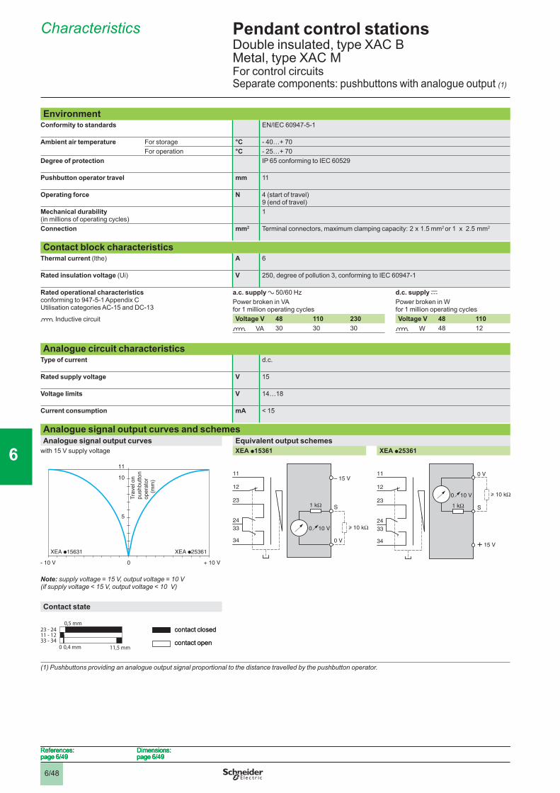
6/48
Pendant control stations 6 Double insulated, type XAC B Metal, type XAC MFor control circuitsSeparate components: pushbuttons with analogue output (1)
Characteristics 6
EnvironmentConformity to standards EN/IEC 60947-5-1
Ambient air temperature For storage °C - 40…+ 70For operation °C - 25…+ 70
Degree of protection IP 65 conforming to IEC 60529
Pushbutton operator travel mm 11
Operating force N 4 (start of travel) 9 (end of travel)
Mechanical durability(in millions of operating cycles)
1
Connection mm2 Terminal connectors, maximum clamping capacity: 2 x 1.5 mm2 or 1 x 2.5 mm2
Contact block characteristicsThermal current (lthe) A 6
Rated insulation voltage (Ui) V 250, degree of pollution 3, conforming to IEC 60947-1
Rated operational characteristics conforming to 947-5-1 Appendix CUtilisation categories AC-15 and DC-13
a.c. supply a 50/60 Hz d.c. supply cPower broken in VA for 1 million operating cycles
Power broken in W for 1 million operating cycles
o Inductive circuit Voltage V 48 110 230 Voltage V 48 110o VA 30 30 30 o W 48 12
Analogue circuit characteristicsType of current d.c.
Rated supply voltage V 15
Voltage limits V 14…18
Current consumption mA < 15
Analogue signal output curves and schemesAnalogue signal output curves Equivalent output schemes
with 15 V supply voltage XEA p15361 XEA p25361
Note: supply voltage = 15 V, output voltage = 10 V (if supply voltage < 15 V, output voltage < 10 V)
Contact state
(1) Pushbuttons providing an analogue output signal proportional to the distance travelled by the pushbutton operator.
- 10 V 0 + 10 V
XEA 15631 XEA 25361
5
10
11
Trav
el o
npu
shbu
tton
oper
ator
(
mm
)
- 10 V 0 + 10 V
XEA 15631 XEA 25361
5
10
11
Trav
el o
npu
shbu
tton
oper
ator
(
mm
)
11
12
23
24
33
34
0 10 V
– 15 V
0 V
S1 kΩ
10 kΩ
11
12
23
24
33
34
0 10 V
– 15 V
0 V
S1 kΩ
10 kΩ
11
12
23
24
33
34
0 10 V
+ 15 V
0 V
S1 kΩ
10 kΩ
11
12
23
24
33
34
0 10 V
+ 15 V
0 V
S1 kΩ
10 kΩ
23 - 2411 - 1233 - 34
0,5 mm
0 11,5 mm0,4 mm
contact closed
contact open
23 - 2411 - 1233 - 34
0,5 mm
0 11,5 mm0,4 mm
contact closed
contact open
References:page 6/49
Dimensions:page 6/49
References:page 6/49
Dimensions:page 6/49
References:page 6/49
Dimensions:page 6/49
References:page 6/49
Dimensions:page 6/49
1
2
3
4
5
6
7
8
9
10
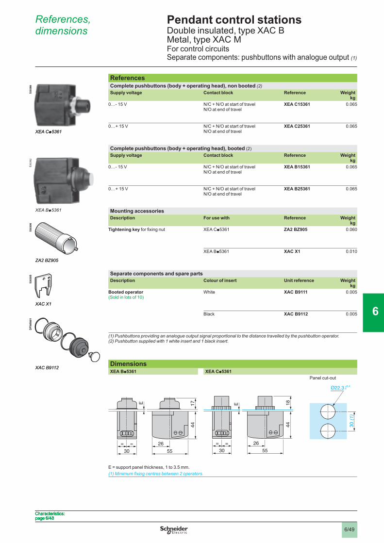
6/49
Pendant control stations 6 Double insulated, type XAC B Metal, type XAC MFor control circuitsSeparate components: pushbuttons with analogue output (1)
References, dimensions 6
ReferencesComplete pushbuttons (body + operating head), non booted (2)Supply voltage Contact block Reference Weight
kg0…- 15 V N/C + N/O at start of travel
N/O at end of travelXEA C15361 0.065
0…+ 15 V N/C + N/O at start of travel N/O at end of travel
XEA C25361 0.065
Complete pushbuttons (body + operating head), booted (2)Supply voltage Contact block Reference Weight
kg0…- 15 V N/C + N/O at start of travel
N/O at end of travelXEA B15361 0.065
0…+ 15 V N/C + N/O at start of travel N/O at end of travel
XEA B25361 0.065
Mounting accessoriesDescription For use with Reference Weight
kgTightening key for fi xing nut XEA Cp5361 ZA2 BZ905 0.060
XEA Bp5361 XAC X1 0.010
Separate components and spare partsDescription Colour of insert Unit reference Weight
kgBooted operator(Sold in lots of 10)
White XAC B9111 0.005
Black XAC B9112 0.005
(1) Pushbuttons providing an analogue output signal proportional to the distance travelled by the pushbutton operator.(2) Pushbutton supplied with 1 white insert and 1 black insert.
DimensionsXEA Bp5361 XEA Cp5361
Panel cut-out
E = support panel thickness, 1 to 3.5 mm.(1) Minimum fi xing centres between 2 operators.
XEA Cp5361
5303
86
XEA Cp5361
5303
86
XEA Bp5361
5303
92
XEA Bp5361
5303
92
ZA2 BZ905
5303
06
ZA2 BZ905
5303
06
XAC X1
5303
05
XAC X1
5303
05
XAC B9112
DF5
6560
1
XAC B9112
DF5
6560
1
17
44
26
55
E
= =
30
17
44
26
55
E
= =
30
18
44
26
55
E
= =
30
18
44
26
55
E
= =
30
30
(1
)
Ø22,3+0,40
30
(1
)
Ø22,3+0,40
Characteristics:page 6/48 Characteristics:page 6/48 Characteristics:page 6/48 Characteristics:page 6/48
1
2
3
4
5
6
7
8
9
10
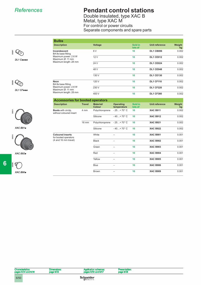
6/50
Pendant control stations 6 Double insulated, type XAC B Metal, type XAC MFor control or power circuitsSeparate components and spare parts
References 6
BulbsDescription Voltage Sold in
lots ofUnit reference Weight
kgIncandescentBA 9s base fi ttingMaximum power: 2.6 W Maximum Ø: 11 mmMaximum length: 28 mm
6 V 10 DL1 CB006 0.002
12 V 10 DL1 CE012 0.002
24 V 10 DL1 CE024 0.002
48 V 10 DL1 CE048 0.002
130 V 10 DL1 CE130 0.002
NeonBA 9s base fi ttingMaximum power: 2.6 W Maximum Ø: 11 mmMaximum length: 28 mm
120 V 10 DL1 CF110 0.002
230 V 10 DL1 CF220 0.002
400 V 10 DL1 CF380 0.002
Accessories for booted operatorsDescription Travel Material/
ColourOperating temperature
Sold in lots of
Unit reference Weightkg
Boots with circlip, without coloured insert
4 mm Polychloroprene - 25…+ 70° C 10 XAC B911 0.002
Silicone - 40…+ 70° C 10 XAC B912 0.002
16 mm Polychloroprene - 25…+ 70° C 10 XAC B921 0.002
Silicone - 40…+ 70° C 10 XAC B922 0.002
Coloured inserts for booted operators (4 and 16 mm travel)
White – 10 XAC B901 0.001
Black – 10 XAC B902 0.001
Green – 10 XAC B903 0.001
Red – 10 XAC B904 0.001
Yellow – 10 XAC B905 0.001
Blue – 10 XAC B906 0.001
Brown – 10 XAC B909 0.001
DL1 Cpppp
5303
07
DL1 Cpppp
5303
07
DL1 CFppp
5303
08
DL1 CFppp
5303
08
XAC B91p
5303
11
XAC B91p
5303
11
XAC B92p
5303
10
XAC B92p
5303
10
XAC B90p
5303
09
XAC B90p
5303
09
Characteristics:pages 6/34 and 6/36
Dimensions:page 6/55
Application schemes:pages 6/56 and 6/57
Presentation:page 6/58
Characteristics:pages 6/34 and 6/36
Dimensions:page 6/55
Application schemes:pages 6/56 and 6/57
Presentation:page 6/58
Characteristics:pages 6/34 and 6/36
Dimensions:page 6/55
Application schemes:pages 6/56 and 6/57
Presentation:page 6/58
Characteristics:pages 6/34 and 6/36
Dimensions:page 6/55
Application schemes:pages 6/56 and 6/57
Presentation:page 6/58
1
2
3
4
5
6
7
8
9
10
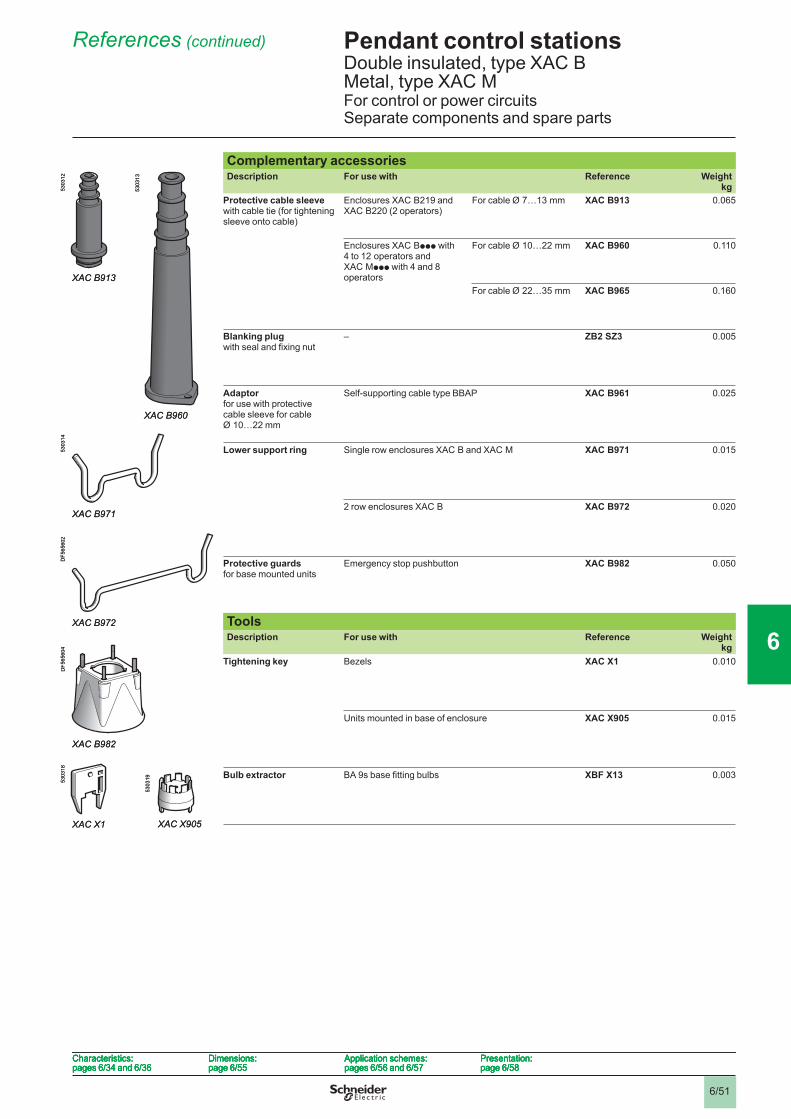
6/51
Pendant control stations 6 Double insulated, type XAC B Metal, type XAC MFor control or power circuitsSeparate components and spare parts
References (continued) 6
Complementary accessoriesDescription For use with Reference Weight
kgProtective cable sleevewith cable tie (for tightening sleeve onto cable)
Enclosures XAC B219 and XAC B220 (2 operators)
For cable Ø 7…13 mm XAC B913 0.065
Enclosures XAC Bppp with 4 to 12 operators and XAC Mppp with 4 and 8 operators
For cable Ø 10…22 mm XAC B960 0.110
For cable Ø 22…35 mm XAC B965 0.160
Blanking plugwith seal and fi xing nut
– ZB2 SZ3 0.005
Adaptorfor use with protective cable sleeve for cable Ø 10…22 mm
Self-supporting cable type BBAP XAC B961 0.025
Lower support ring Single row enclosures XAC B and XAC M XAC B971 0.015
2 row enclosures XAC B XAC B972 0.020
Protective guards for base mounted units
Emergency stop pushbutton XAC B982 0.050
ToolsDescription For use with Reference Weight
kgTightening key Bezels XAC X1 0.010
Units mounted in base of enclosure XAC X905 0.015
Bulb extractor BA 9s base fi tting bulbs XBF X13 0.003
XAC B913
5303
12
5303
13
XAC B960
XAC B913
5303
12
5303
13
XAC B960
XAC B971
5303
14
XAC B971
5303
14
XAC B972
DF5
6560
2
XAC B972
DF5
6560
2
XAC B982
DF5
6560
4
XAC B982
DF5
6560
4
XAC X1
5303
18
5303
19
XAC X905XAC X1
5303
18
5303
19
XAC X905
Characteristics:pages 6/34 and 6/36
Dimensions:page 6/55
Application schemes:pages 6/56 and 6/57
Presentation:page 6/58
Characteristics:pages 6/34 and 6/36
Dimensions:page 6/55
Application schemes:pages 6/56 and 6/57
Presentation:page 6/58
Characteristics:pages 6/34 and 6/36
Dimensions:page 6/55
Application schemes:pages 6/56 and 6/57
Presentation:page 6/58
Characteristics:pages 6/34 and 6/36
Dimensions:page 6/55
Application schemes:pages 6/56 and 6/57
Presentation:page 6/58
1
2
3
4
5
6
7
8
9
10
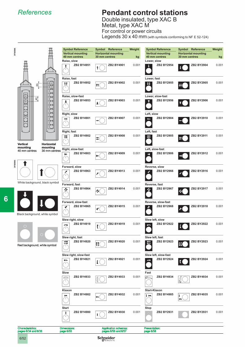
6/52
Pendant control stations 6 Double insulated, type XAC B Metal, type XAC MFor control or power circuitsLegends 30 x 40 mm (with symbols conforming to NF E 52-124)
References 6
Symbol Reference Symbol Reference Weight Symbol Reference Symbol Reference WeightVertical mounting 40 mm centres
Horizontal mounting30 mm centres kg
Vertical mounting40 mm centres
Horizontal mounting30 mm centres kg
Raise, slow Lower, slowZB2 BY4951 ZB2 BY4901 0.001 ZB2 BY2954 ZB2 BY2904 0.001
Raise, fast Lower, fastZB2 BY4952 ZB2 BY4902 0.001 ZB2 BY2955 ZB2 BY2905 0.001
Raise, slow-fast Lower, slow-fastZB2 BY4953 ZB2 BY4903 0.001 ZB2 BY2956 ZB2 BY2906 0.001
Right, slow Left, slowZB2 BY4901 ZB2 BY4907 0.001 ZB2 BY2904 ZB2 BY2910 0.001
Right, fast Left, fastZB2 BY4902 ZB2 BY4908 0.001 ZB2 BY2905 ZB2 BY2911 0.001
Right, slow-fast Left, slow-fastZB2 BY4903 ZB2 BY4909 0.001 ZB2 BY2906 ZB2 BY2912 0.001
Forward, slow Reverse, slowZB2 BY4963 ZB2 BY4913 0.001 ZB2 BY2966 ZB2 BY2916 0.001
Forward, fast Reverse, fastZB2 BY4964 ZB2 BY4914 0.001 ZB2 BY2967 ZB2 BY2917 0.001
Forward, slow-fast Reverse, slow-fastZB2 BY4965 ZB2 BY4915 0.001 ZB2 BY2968 ZB2 BY2918 0.001
Slew right, slow Slew left, slowZB2 BY4919 ZB2 BY4919 0.001 ZB2 BY2922 ZB2 BY2922 0.001
Slew right, fast Slew left, fastZB2 BY4920 ZB2 BY4920 0.001 ZB2 BY2923 ZB2 BY2923 0.001
Slew right, slow-fast Slew left, slow-fastZB2 BY4921 ZB2 BY4921 0.001 ZB2 BY2924 ZB2 BY2924 0.001
Slow FastZB2 BY4933 ZB2 BY4933 0.001 ZB2 BY4934 ZB2 BY4934 0.001
Klaxon Start-KlaxonZB2 BY4982 ZB2 BY4932 0.001 ZB2 BY4985 ZB2 BY4935 0.001
Start StopZB2 BY4980 ZB2 BY4930 0.001 ZB2 BY2931 ZB2 BY2931 0.001
30
40
DF5
6566
6
Vertical mounting 40 mm centres
Horizontal mounting 30 mm centres
30
40
DF5
6566
6
Vertical mounting 40 mm centres
Horizontal mounting 30 mm centres
White background, black symbol
DF5
6566
5
Black background, white symbol
Red background, white symbol
White background, black symbol
DF5
6566
5
Black background, white symbol
Red background, white symbol
Characteristics:pages 6/34 and 6/36
Dimensions:page 6/55
Application schemes:pages 6/56 and 6/57
Presentation:page 6/58
Characteristics:pages 6/34 and 6/36
Dimensions:page 6/55
Application schemes:pages 6/56 and 6/57
Presentation:page 6/58
Characteristics:pages 6/34 and 6/36
Dimensions:page 6/55
Application schemes:pages 6/56 and 6/57
Presentation:page 6/58
Characteristics:pages 6/34 and 6/36
Dimensions:page 6/55
Application schemes:pages 6/56 and 6/57
Presentation:page 6/58
1
2
3
4
5
6
7
8
9
10
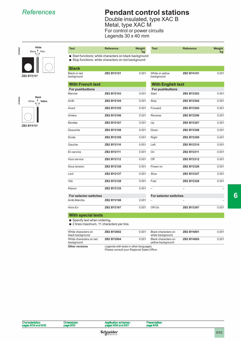
6/53
Pendant control stations 6 Double insulated, type XAC B Metal, type XAC MFor control or power circuitsLegends 30 x 40 mm
References 6
Text Reference Weightkg
Text Reference Weightkg
Start functions: white characters on black backgroundStop functions: white characters on red background
bb
BlankBlack or red background
ZB2 BY2101 0.001 White or yellow background
ZB2 BY4101 0.001
With French text With English textFor pushbuttons For pushbuttons
Marche ZB2 BY2103 0.001 Start ZB2 BY2303 0.001
Arrêt ZB2 BY2104 0.001 Stop ZB2 BY2304 0.001
Avant ZB2 BY2105 0.001 Forward ZB2 BY2305 0.001
Arrière ZB2 BY2106 0.001 Reverse ZB2 BY2306 0.001
Montée ZB2 BY2107 0.001 Up ZB2 BY2307 0.001
Descente ZB2 BY2108 0.001 Down ZB2 BY2308 0.001
Droite ZB2 BY2109 0.001 Right ZB2 BY2309 0.001
Gauche ZB2 BY2110 0.001 Left ZB2 BY2310 0.001
En service ZB2 BY2111 0.001 On ZB2 BY2311 0.001
Hors service ZB2 BY2112 0.001 Off ZB2 BY2312 0.001
Sous tension ZB2 BY2126 0.001 Power on ZB2 BY2326 0.001
Lent ZB2 BY2127 0.001 Slow ZB2 BY2327 0.001
Vite ZB2 BY2128 0.001 Fast ZB2 BY2328 0.001
Klaxon ZB2 BY2125 0.001 – – –
For selector switches For selector switchesArrêt-Marche ZB2 BY2166 0.001 – – –
Hors-En ZB2 BY2167 0.001 Off-On ZB2 BY2367 0.001
With special texts Specify text when ordering,2 lines maximum, 11 characters per line.
bb
White characters on black background
ZB2 BY2002 0.001 Black characters on white background
ZB2 BY4001 0.001
White characters on red background
ZB2 BY2004 0.001 Black characters on yellow background
ZB2 BY4005 0.001
Other versions Legends with texts in other languages.Please consult your Regional Sales Offi ce.
DF5
6566
7
ZB2 BY2101
RedWhite
Black
DF5
6566
7
ZB2 BY2101
RedWhite
Black
DF5
6566
8
ZB2 BY4101
YellowBlack
White
DF5
6566
8
ZB2 BY4101
YellowBlack
White
Characteristics:pages 6/34 and 6/36
Dimensions:page 6/55
Application schemes:pages 6/56 and 6/57
Presentation:page 6/58
Characteristics:pages 6/34 and 6/36
Dimensions:page 6/55
Application schemes:pages 6/56 and 6/57
Presentation:page 6/58
Characteristics:pages 6/34 and 6/36
Dimensions:page 6/55
Application schemes:pages 6/56 and 6/57
Presentation:page 6/58
Characteristics:pages 6/34 and 6/36
Dimensions:page 6/55
Application schemes:pages 6/56 and 6/57
Presentation:page 6/58
1
2
3
4
5
6
7
8
9
10
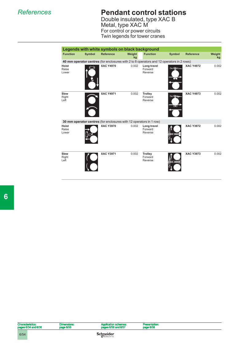
6/54
Pendant control stations 6 Double insulated, type XAC B Metal, type XAC MFor control or power circuitsTwin legends for tower cranes
References 6
Legends with white symbols on black backgroundFunction Symbol Reference Weight
kgFunction Symbol Reference Weight
kg40 mm operator centres (for enclosures with 2 to 8 operators and 12 operators in 2 rows)
HoistRaiseLower
XAC Y4970 0.002 Long travelForwardReverse
XAC Y4972 0.002
SlewRightLeft
XAC Y4971 0.002 TrolleyForwardReverse
XAC Y4973 0.002
30 mm operator centres (for enclosures with 12 operators in 1 row)HoistRaiseLower
XAC Y3970 0.002 Long travelForwardReverse
XAC Y3972 0.002
SlewRightLeft
XAC Y3971 0.002 TrolleyForwardReverse
XAC Y3973 0.002
Characteristics:pages 6/34 and 6/36
Dimensions:page 6/55
Application schemes:pages 6/56 and 6/57
Presentation:page 6/58
Characteristics:pages 6/34 and 6/36
Dimensions:page 6/55
Application schemes:pages 6/56 and 6/57
Presentation:page 6/58
Characteristics:pages 6/34 and 6/36
Dimensions:page 6/55
Application schemes:pages 6/56 and 6/57
Presentation:page 6/58
Characteristics:pages 6/34 and 6/36
Dimensions:page 6/55
Application schemes:pages 6/56 and 6/57
Presentation:page 6/58
1
2
3
4
5
6
7
8
9
10
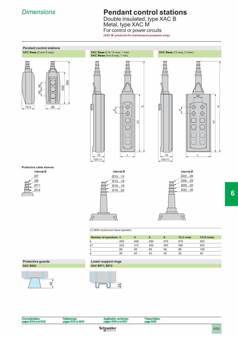
6/55
Pendant control stations 6 Double insulated, type XAC B Metal, type XAC M For control or power circuits(XAC M: products for maintenance purposes only)
Dimensions 6
Pendant control stationsXAC Bppp (2 and 3-way) XAC Bppp (2 to 12-way, 1 row)
XAC Mppp (4 to 8-way, 1 row)XAC Bppp (12-way, 2 rows)
Protective cable sleeves
(1) With mushroom head operator.
Number of operators 2 4 6 8 12 (1 row) 12 (2 rows)b 409 499 589 679 679 593b1 220 310 400 490 490 404c 98 98 98 98 98 158d 40 40 40 40 30 40
Protective guards Lower support ringsXAC B982 XAC B971, B972
74,5 85
200
265
40
40
74,5 85
200
265
40
40
c
d
b
b1
76
100 (1)
c
d
b
b1
76
100 (1)
76
100 (1)
c
d
b
b1
60
76
100 (1)
c
d
b
b1
60
Ø9
Ø11
Ø14
Ø7
internal Ø
Ø9
Ø11
Ø14
Ø7
internal Ø
Ø10…13
Ø13…16
Ø16…19
Ø19…22
internal Ø
Ø10…13
Ø13…16
Ø16…19
Ø19…22
internal ØØ22…26
Ø26…29
Ø29…32
Ø32…35
internal ØØ22…26
Ø26…29
Ø29…32
Ø32…35
internal Ø
4848
24
24
Characteristics:pages 6/34 and 6/36
References:pages 6/35 to 6/54
Application schemes:pages 6/56 and 6/57
Presentation:page 6/58
Characteristics:pages 6/34 and 6/36
References:pages 6/35 to 6/54
Application schemes:pages 6/56 and 6/57
Presentation:page 6/58
Characteristics:pages 6/34 and 6/36
References:pages 6/35 to 6/54
Application schemes:pages 6/56 and 6/57
Presentation:page 6/58
Characteristics:pages 6/34 and 6/36
References:pages 6/35 to 6/54
Application schemes:pages 6/56 and 6/57
Presentation:page 6/58
1
2
3
4
5
6
7
8
9
10

6/56
Pendant control stations 6 Double insulated, type XAC B Metal, type XAC MFor control or power circuits
Application schemes (typical examples) 6
Control circuitsFor control of single-speed reversing motor For control of 2-speed reversing motorContact block XES D1181 Contact block XES D1281
KM: high speed contactor
Power circuitsFor control of single-speed reversing motor. 2-phase switchingContact block XES D1191 Application example:
Combined with 3-pole isolating block XAC S399 or XAC S3991, shown in the unoperated position (pendant station “supplied”), fi tted with key release trigger action latching Emergency stop operator (ZA2 BS944).
13
14
11
12
23
24
21
22
A1
A2
– KM2
– S1
A1
A2
– KM1
– S2
13
14
11
12
23
24
21
22
A1
A2
– KM2
– S1
A1
A2
– KM1
– S2
34
43
44
13
33
14
11
12
23
24
21
22
A1
A2
– KM2
A1
A2
– KM
– S1
A1
A2
– KM1
– S2
34
43
44
13
33
14
11
12
23
24
21
22
A1
A2
– KM2
A1
A2
– KM
– S1
A1
A2
– KM1
– S2
– S1
L1 L2 L3
– S2
13
14
23
24
33
34
43
44
U WV1
1
21
31
12
22
32
Q
– S1
L1 L2 L3
– S2
13
14
23
24
33
34
43
44
U WV1
1
21
31
12
22
32
Q
– S1
L1 L2 L3
– S2
13
14
23
24
33
34
43
44
U WV
– S1
L1 L2 L3
– S2
13
14
23
24
33
34
43
44
U WV
Characteristics:pages 6/34 and 6/36
References:pages 6/35 to 6/54
Dimensions:page 6/55
Presentation:page 6/58
Characteristics:pages 6/34 and 6/36
References:pages 6/35 to 6/54
Dimensions:page 6/55
Presentation:page 6/58
Characteristics:pages 6/34 and 6/36
References:pages 6/35 to 6/54
Dimensions:page 6/55
Presentation:page 6/58
Characteristics:pages 6/34 and 6/36
References:pages 6/35 to 6/54
Dimensions:page 6/55
Presentation:page 6/58
1
2
3
4
5
6
7
8
9
10
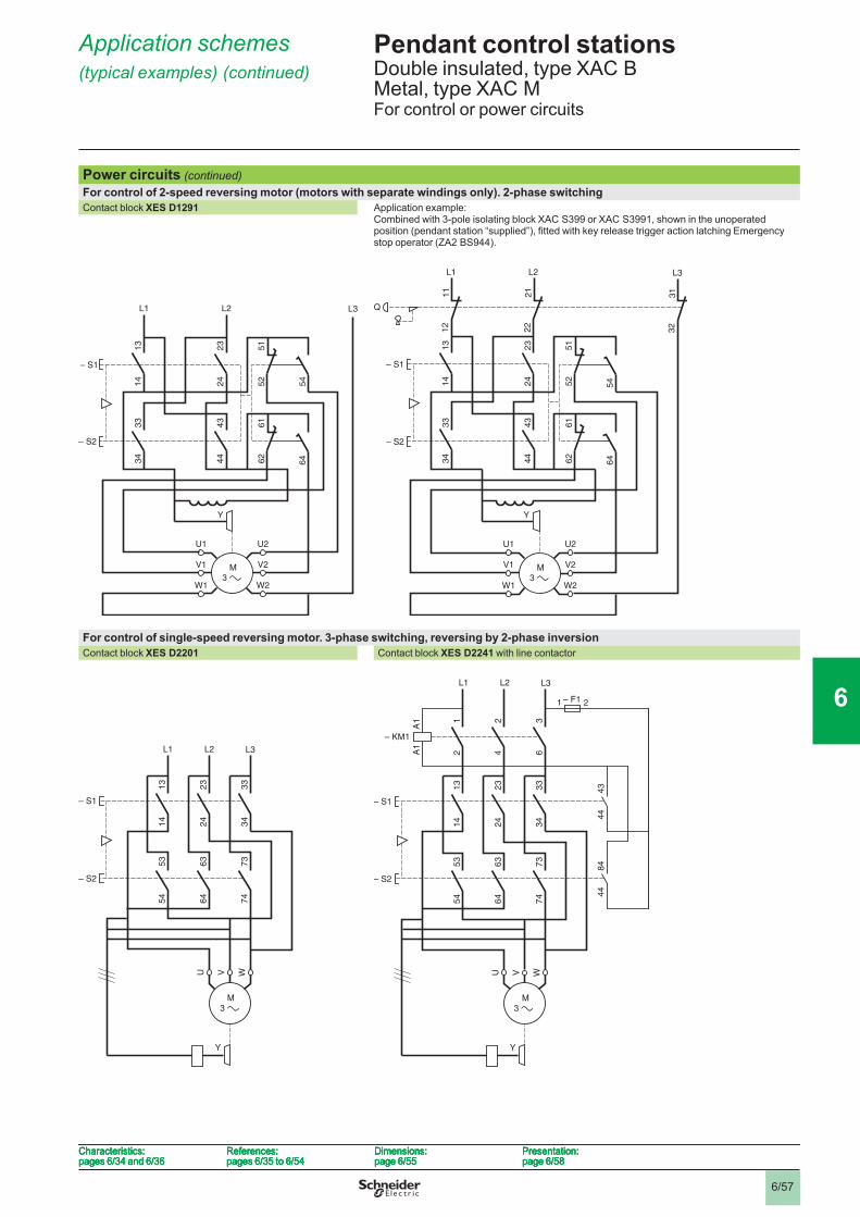
6/57
Pendant control stations 6 Double insulated, type XAC B Metal, type XAC MFor control or power circuits
Application schemes (typical examples) (continued) 6
Power circuits (continued)For control of 2-speed reversing motor (motors with separate windings only). 2-phase switchingContact block XES D1291 Application example:
Combined with 3-pole isolating block XAC S399 or XAC S3991, shown in the unoperated position (pendant station “supplied”), fi tted with key release trigger action latching Emergency stop operator (ZA2 BS944).
For control of single-speed reversing motor. 3-phase switching, reversing by 2-phase inversionContact block XES D2201 Contact block XES D2241 with line contactor
– S1
– S2
54
L1
11
12
L2
21
22
Q
13
14
23
24
51
52
33
34
43
44
61
62
64
U2
V2
W2
U1
V1
W1
Y
L3
31
32
– S1
– S2
54
L1
11
12
L2
21
22
Q
13
14
23
24
51
52
33
34
43
44
61
62
64
U2
V2
W2
U1
V1
W1
Y
L3
31
32
L1 L2 L3
– S1
– S2
13
14
23
24
51
52
33
34
43
44
61
62
64
U2
V2
W2
U1
V1
W1
Y
54
L1 L2 L3
– S1
– S2
13
14
23
24
51
52
33
34
43
44
61
62
64
U2
V2
W2
U1
V1
W1
Y
54
L1 L2 L3
13
14
23
24
33
34
53
54
63
64
73
74
– S1
– S2
Y
U V W
L1 L2 L3
13
14
23
24
33
34
53
54
63
64
73
74
– S1
– S2
Y
U V W
A1
A1
L1 L2 L3
13
14
23
24
33
34
53
54
63
64
73
74
12
24
36
– S1
– S2
U V W
– F1 21
43
44
84
44
– KM1
Y
A1
A1
L1 L2 L3
13
14
23
24
33
34
53
54
63
64
73
74
12
24
36
– S1
– S2
U V W
– F1 21
43
44
84
44
– KM1
Y
Characteristics:pages 6/34 and 6/36
References:pages 6/35 to 6/54
Dimensions:page 6/55
Presentation:page 6/58
Characteristics:pages 6/34 and 6/36
References:pages 6/35 to 6/54
Dimensions:page 6/55
Presentation:page 6/58
Characteristics:pages 6/34 and 6/36
References:pages 6/35 to 6/54
Dimensions:page 6/55
Presentation:page 6/58
Characteristics:pages 6/34 and 6/36
References:pages 6/35 to 6/54
Dimensions:page 6/55
Presentation:page 6/58
1
2
3
4
5
6
7
8
9
10
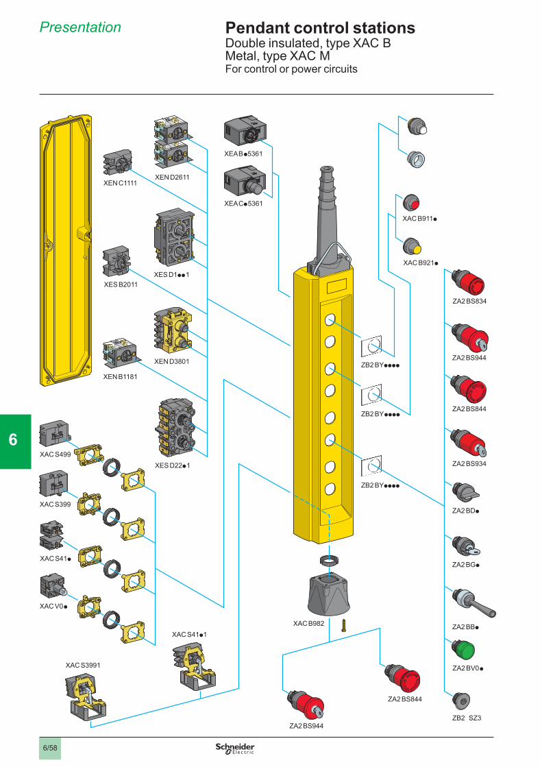
6/58
Pendant control stations 6 Double insulated, type XAC B Metal, type XAC MFor control or power circuits
Presentation 6
ZB2 SZ3
ZA2 BV0 p
ZB2 BYpppp
ZB2 BY pppp
ZB2 BYpppp
XAC B911p
XAC B921p
ZA2 BBp
ZA2 BGp
ZA2 BDp
ZA2 BS934
ZA2 BS844
ZA2 BS944
ZA2 BS834
ZA2 BS844
ZA2 BS944
XAC B982
XAC S3991
XAC S499
XAC S399
XAC S41p
XAC S41p1
XAC V0 p
XES B2011
XEN C1111XEN D2611
XEN D3801
XEN B1181
XES D1pp 1
XES D22p 1
XEA B p5361
XEA Cp 5361
1
2
3
4
5
6
7
8
9
10
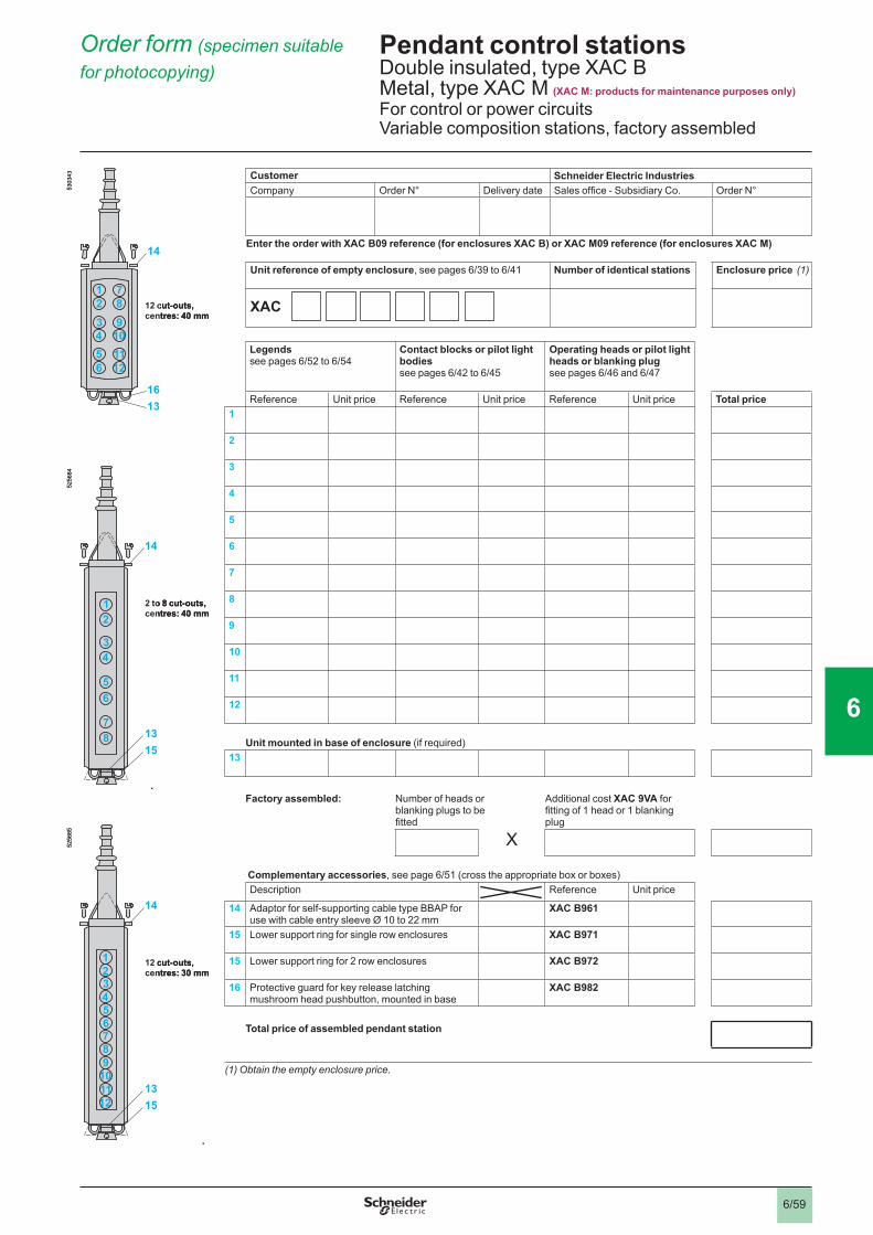
6/59
Pendant control stations 6 Double insulated, type XAC B Metal, type XAC M (XAC M: products for maintenance purposes only) For control or power circuitsVariable composition stations, factory assembled
Order form (specimen suitable for photocopying) 6
Customer Schneider Electric IndustriesCompany Order N° Delivery date Sales offi ce - Subsidiary Co. Order N°
Enter the order with XAC B09 reference (for enclosures XAC B) or XAC M09 reference (for enclosures XAC M)
Unit reference of empty enclosure, see pages 6/39 to 6/41 Number of identical stations Enclosure price (1)
XAC
Legendssee pages 6/52 to 6/54
Contact blocks or pilot light bodiessee pages 6/42 to 6/45
Operating heads or pilot light heads or blanking plug see pages 6/46 and 6/47
Reference Unit price Reference Unit price Reference Unit price Total price1
2
3
4
5
6
7
8
9
10
11
12
Unit mounted in base of enclosure (if required)13
Factory assembled: Number of heads or blanking plugs to be fi tted
Additional cost XAC 9VA for fi tting of 1 head or 1 blanking plug
X
Complementary accessories, see page 6/51 (cross the appropriate box or boxes)Description Reference Unit price
14 Adaptor for self-supporting cable type BBAP for use with cable entry sleeve Ø 10 to 22 mm
XAC B961
15 Lower support ring for single row enclosures XAC B971
15 Lower support ring for 2 row enclosures XAC B972
16 Protective guard for key release latching mushroom head pushbutton, mounted in base
XAC B982
Total price of assembled pendant station
(1) Obtain the empty enclosure price.
14
1316
1211
910
78
65
34
12
5303
43
12 cut-outs, centres: 40 mm
14
1316
1211
910
78
65
34
12
5303
43
12 cut-outs, centres: 40 mm
14
15138
7
65
43
21
5256
84
2 to 8 cut-outs, centres: 40 mm
14
15138
7
65
43
21
5256
84
2 to 8 cut-outs, centres: 40 mm
14
1513
87654321
9101112
5256
85
12 cut-outs, centres: 30 mm
14
1513
87654321
9101112
5256
85
12 cut-outs, centres: 30 mm
1
2
3
4
5
6
7
8
9
10
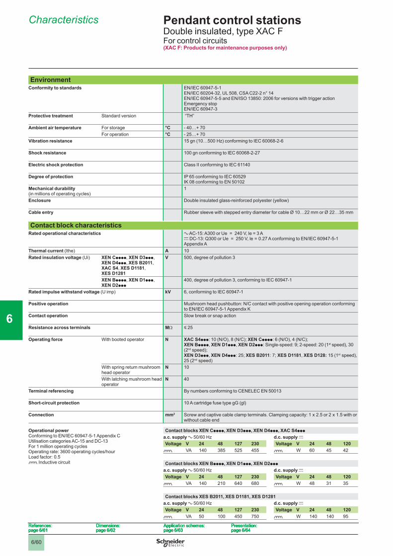
6/60
Pendant control stations 6 Double insulated, type XAC FFor control circuits(XAC F: Products for maintenance purposes only)
EnvironmentConformity to standards EN/IEC 60947-5-1
EN/IEC 60204-32, UL 508, CSA C22-2 n° 14EN/IEC 60947-5-5 and EN/ISO 13850: 2006 for versions with trigger action Emergency stop EN/IEC 60947-3
Protective treatment Standard version “TH”
Ambient air temperature For storage °C - 40…+ 70For operation °C - 25…+ 70
Vibration resistance 15 gn (10…500 Hz) conforming to IEC 60068-2-6
Shock resistance 100 gn conforming to IEC 60068-2-27
Electric shock protection Class II conforming to IEC 61140
Degree of protection IP 65 conforming to IEC 60529 IK 08 conforming to EN 50102
Mechanical durability(in millions of operating cycles)
1
Enclosure Double insulated glass-reinforced polyester (yellow)
Cable entry Rubber sleeve with stepped entry diameter for cable Ø 10…22 mm or Ø 22…35 mm
Contact block characteristicsRated operational characteristics a AC-15: A300 or Ue = 240 V, le = 3 A
c DC-13: Q300 or Ue = 250 V, le = 0.27 A conforming to EN/IEC 60947-5-1 Appendix A
Thermal current (lthe) A 10Rated insulation voltage (Ui) XEN Cpppp, XEN D3ppp,
XEN D4ppp, XES B2011, XAC S4, XES D1181, XES D1281
V 500, degree of pollution 3
XEN Bpppp, XEN D1ppp, XEN D2ppp
400, degree of pollution 3, conforming to IEC 60947-1
Rated impulse withstand voltage (U imp) kV 6, conforming to IEC 60947-1
Positive operation Mushroom head pushbutton: N/C contact with positive opening operation conforming to EN/IEC 60947-5-1 Appendix K
Contact operation Slow break or snap action
Resistance across terminals MΩ y 25
Operating force With booted operator N XAC S4ppp: 10 (N/O), 8 (N/C); XEN Cpppp: 6 (N/O), 4 (N/C);XEN Bpppp, XEN D1ppp, XEN D2ppp: Single-speed: 9; 2-speed: 20 (1st speed), 30 (2nd speed); XEN D3ppp, XEN D4ppp: 25; XES B2011: 7; XES D1181, XES D128: 15 (1st speed), 25 (2nd speed)
With spring return mushroom head operator
N 10
With latching mushroom head operator
N 40
Terminal referencing By numbers conforming to CENELEC EN 50013
Short-circuit protection 10 A cartridge fuse type gG (gl)
Connection mm2 Screw and captive cable clamp terminals. Clamping capacity: 1 x 2.5 or 2 x 1.5 with or without cable end
Operational powerConforming to EN/IEC 60947-5-1 Appendix CUtilisation categories AC-15 and DC-13For 1 million operating cyclesOperating rate: 3600 operating cycles/hourLoad factor: 0.5o Inductive circuit
Contact blocks XEN Cpppp, XEN D3ppp, XEN D4ppp, XAC S4ppp
a.c. supply a 50/60 Hz d.c. supply cVoltage V 24 48 127 230 Voltage V 24 48 120
o VA 140 385 525 455 o W 60 45 42
Contact blocks XEN Bpppp, XEN D1ppp, XEN D2ppp
a.c. supply a 50/60 Hz d.c. supply cVoltage V 24 48 127 230 Voltage V 24 48 120
o VA 140 210 640 680 o W 48 31 35
Contact blocks XES B2011, XES D1181, XES D1281a.c. supply a 50/60 Hz d.c. supply cVoltage V 24 48 127 230 Voltage V 24 48 120
o VA 50 100 450 750 o W 140 140 95 References:
page 6/61 Dimensions:page 6/62
Application schemes:page 6/63
Presentation:page 6/64
References:page 6/61
Dimensions:page 6/62
Application schemes:page 6/63
Presentation:page 6/64
References:page 6/61
Dimensions:page 6/62
Application schemes:page 6/63
Presentation:page 6/64
References:page 6/61
Dimensions:page 6/62
Application schemes:page 6/63
Presentation:page 6/64
Characteristics 6
1
2
3
4
5
6
7
8
9
10
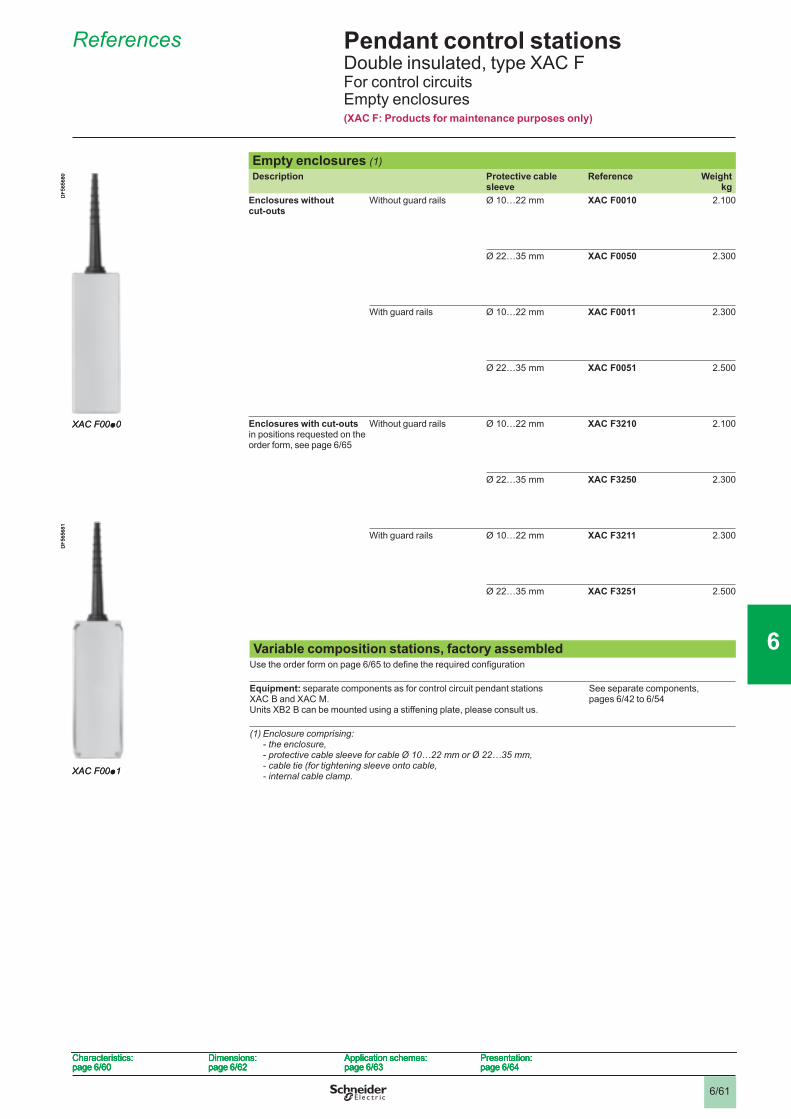
6/61
Pendant control stations 6 Double insulated, type XAC FFor control circuitsEmpty enclosures(XAC F: Products for maintenance purposes only)
Empty enclosures (1)Description Protective cable
sleeveReference Weight
kgEnclosures without cut-outs
Without guard rails Ø 10…22 mm XAC F0010 2.100
Ø 22…35 mm XAC F0050 2.300
With guard rails Ø 10…22 mm XAC F0011 2.300
Ø 22…35 mm XAC F0051 2.500
Enclosures with cut-outs in positions requested on the order form, see page 6/65
Without guard rails Ø 10…22 mm XAC F3210 2.100
Ø 22…35 mm XAC F3250 2.300
With guard rails Ø 10…22 mm XAC F3211 2.300
Ø 22…35 mm XAC F3251 2.500
Variable composition stations, factory assembledUse the order form on page 6/65 to defi ne the required confi guration
Equipment: separate components as for control circuit pendant stations XAC B and XAC M.Units XB2 B can be mounted using a stiffening plate, please consult us.
See separate components, pages 6/42 to 6/54
(1) Enclosure comprising:- the enclosure,- protective cable sleeve for cable Ø 10…22 mm or Ø 22…35 mm,- cable tie (for tightening sleeve onto cable,- internal cable clamp.
XAC F00p0
DF5
6568
0
XAC F00p0
DF5
6568
0
XAC F00p1
DF5
6568
1
XAC F00p1
DF5
6568
1
Characteristics:page 6/60
Dimensions:page 6/62
Application schemes:page 6/63
Presentation:page 6/64
Characteristics:page 6/60
Dimensions:page 6/62
Application schemes:page 6/63
Presentation:page 6/64
Characteristics:page 6/60
Dimensions:page 6/62
Application schemes:page 6/63
Presentation:page 6/64
Characteristics:page 6/60
Dimensions:page 6/62
Application schemes:page 6/63
Presentation:page 6/64
References 6
1
2
3
4
5
6
7
8
9
10
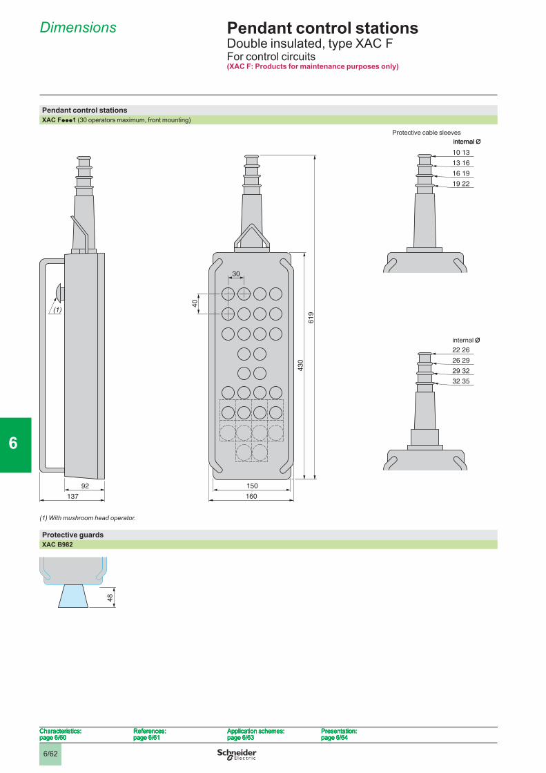
6/62
Pendant control stations 6 Double insulated, type XAC FFor control circuits(XAC F: Products for maintenance purposes only)
Pendant control stationsXAC Fppp1 (30 operators maximum, front mounting)
(1) With mushroom head operator.
Protective guards XAC B982
10 13
13 16
16 19
19 22
30
150
160
61
9
43
0
40
22 26
26 29
29 32
32 35
92
137
(1)
internal Ø
internal Ø
10 13
13 16
16 19
19 22
30
150
160
61
9
43
0
40
22 26
26 29
29 32
32 35
92
137
(1)
internal Ø
internal Ø
4848
Characteristics:page 6/60
References:page 6/61
Application schemes:page 6/63
Presentation:page 6/64
Characteristics:page 6/60
References:page 6/61
Application schemes:page 6/63
Presentation:page 6/64
Characteristics:page 6/60
References:page 6/61
Application schemes:page 6/63
Presentation:page 6/64
Characteristics:page 6/60
References:page 6/61
Application schemes:page 6/63
Presentation:page 6/64
Protective cable sleeves
Dimensions 6
1
2
3
4
5
6
7
8
9
10
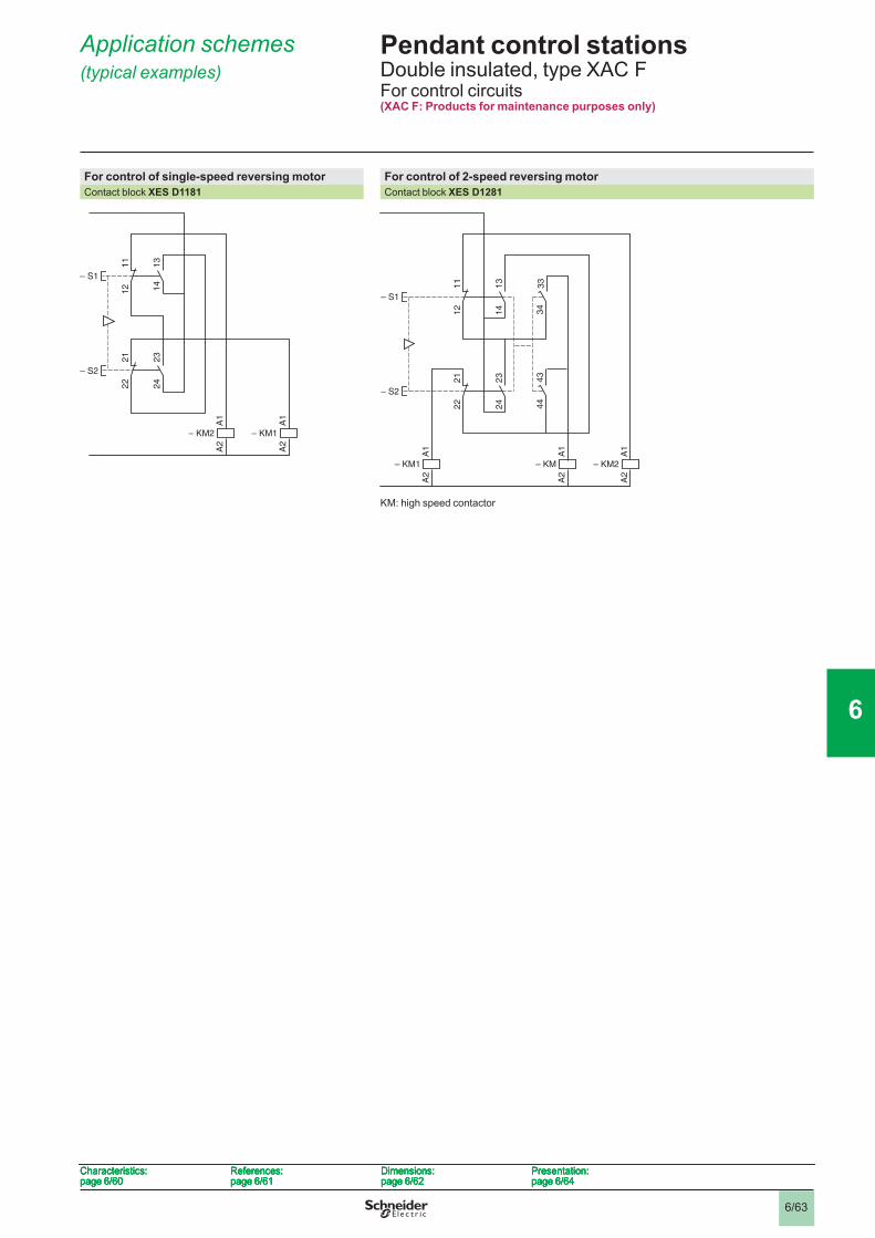
6/63
Pendant control stations 6 Double insulated, type XAC FFor control circuits(XAC F: Products for maintenance purposes only)
For control of single-speed reversing motor For control of 2-speed reversing motorContact block XES D1181 Contact block XES D1281
KM: high speed contactor
13
14
11
12
23
24
21
22
A1
A2
– KM2
– S1A
1A
2
– KM1
– S2
13
14
11
12
23
24
21
22
A1
A2
– KM2
– S1A
1A
2
– KM1
– S2
34
43
44
13
33
14
11
12
23
24
21
22
A1
A2
– KM2
A1
A2
– KM
– S1
A1
A2
– KM1
– S2
34
43
44
13
33
14
11
12
23
24
21
22
A1
A2
– KM2
A1
A2
– KM
– S1
A1
A2
– KM1
– S2
Characteristics:page 6/60
References:page 6/61
Dimensions:page 6/62
Presentation:page 6/64
Characteristics:page 6/60
References:page 6/61
Dimensions:page 6/62
Presentation:page 6/64
Characteristics:page 6/60
References:page 6/61
Dimensions:page 6/62
Presentation:page 6/64
Characteristics:page 6/60
References:page 6/61
Dimensions:page 6/62
Presentation:page 6/64
Application schemes (typical examples) 6
1
2
3
4
5
6
7
8
9
10
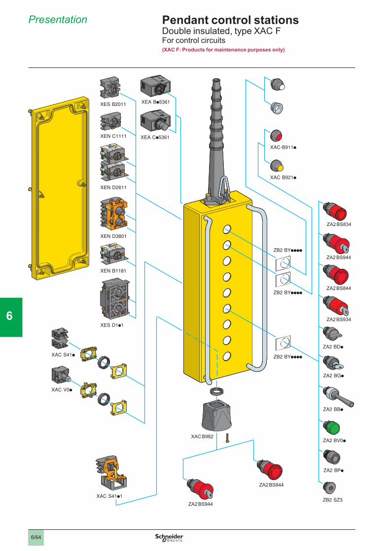
6/64
Pendant control stations 6 Double insulated, type XAC FFor control circuits(XAC F: Products for maintenance purposes only)
Presentation 6
XAC B982
1
2
3
4
5
6
7
8
9
10
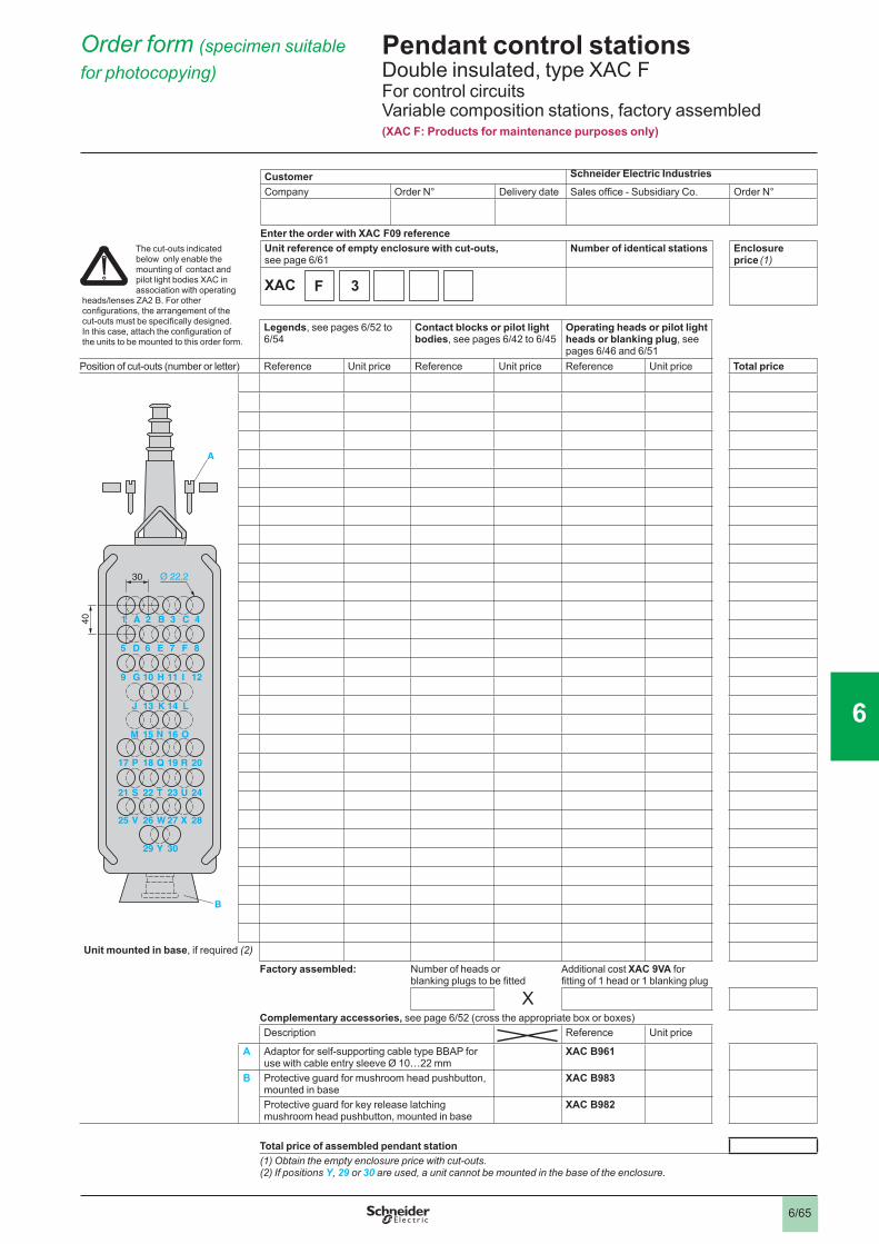
6/65
Pendant control stations 6 Double insulated, type XAC FFor control circuitsVariable composition stations, factory assembled (XAC F: Products for maintenance purposes only)
Customer Schneider Electric Industries
Company Order N° Delivery date Sales offi ce - Subsidiary Co. Order N°
Enter the order with XAC F09 referenceUnit reference of empty enclosure with cut-outs,see page 6/61
Number of identical stations Enclosure price (1)
XAC
Legends, see pages 6/52 to 6/54
Contact blocks or pilot light bodies, see pages 6/42 to 6/45
Operating heads or pilot light heads or blanking plug, see pages 6/46 and 6/51
Position of cut-outs (number or letter) Reference Unit price Reference Unit price Reference Unit price Total price
Unit mounted in base, if required (2)
Factory assembled: Number of heads or blanking plugs to be fi tted
Additional cost XAC 9VA for fi tting of 1 head or 1 blanking plug
XComplementary accessories, see page 6/52 (cross the appropriate box or boxes)Description Reference Unit price
A Adaptor for self-supporting cable type BBAP for use with cable entry sleeve Ø 10…22 mm
XAC B961
B Protective guard for mushroom head pushbutton, mounted in base
XAC B983
Protective guard for key release latching mushroom head pushbutton, mounted in base
XAC B982
Total price of assembled pendant station(1) Obtain the empty enclosure price with cut-outs.(2) If positions Y, 29 or 30 are used, a unit cannot be mounted in the base of the enclosure.
1 A 2 B 3 C 4
5 D 6 E 7 F 8
9 G 10 H 11 I 12
J 13 K 14 L
M 15 N 16 O
P 18 Q 19 R17 20
S 22 T 23 U21 24
V 26 W 27 X25 28
29 Y 30
30
40
Ø 22,2
B
A
1 A 2 B 3 C 4
5 D 6 E 7 F 8
9 G 10 H 11 I 12
J 13 K 14 L
M 15 N 16 O
P 18 Q 19 R17 20
S 22 T 23 U21 24
V 26 W 27 X25 28
29 Y 30
30
40
Ø 22,2
B
A
F 3
Order form (specimen suitable for photocopying) 6
The cut-outs indicated below only enable the mounting of contact and pilot light bodies XAC in association with operating
heads/lenses ZA2 B. For other confi gurations, the arrangement of the cut-outs must be specifi cally designed.In this case, attach the confi guration ofthe units to be mounted to this order form.
1
2
3
4
5
6
7
8
9
10
Top Related