
ZONGE GGT-30 GEOPHYSICAL TRANSMITTER … GGT-30 GEOPHYSICAL TRANSMITTER MAINTENANCE and REPAIR...
46
ZONGE GGT-30 GEOPHYSICAL TRANSMITTER MAINTENANCE and REPAIR MANUAL June 2001 Zonge International 3322 East Fort Lowell Road, Tucson, AZ 85716 USA Phone (520) 327-5501 Facsimile (520) 325-1588
Transcript of ZONGE GGT-30 GEOPHYSICAL TRANSMITTER … GGT-30 GEOPHYSICAL TRANSMITTER MAINTENANCE and REPAIR...
ZONGE GGT-30
GEOPHYSICAL TRANSMITTER
MAINTENANCE and REPAIR MANUAL
June 2001
Zonge International 3322 East Fort Lowell Road, Tucson, AZ 85716 USA Phone (520) 327-5501 Facsimile (520) 325-1588

GGT-30 Manual Zonge International 2
Blank Page

GGT-30 Manual Zonge International 3
TABLE OF CONTENTS
TABLE OF FIGURES ................................................................................. 4
1. INTRODUCTION ............................................................................. 5
2. GGT-30 SPECIFICATIONS ............................................................. 6 2.1. Electrical ...................................................................................... 6 2.2. Mechanical .................................................................................. 6 2.3. Electronics ................................................................................... 6 2.4. Front Panel Controls .................................................................... 7 2.5. Controls ....................................................................................... 7 2.6. External Control ........................................................................... 7
3. OPERATING INSTRUCTIONS ........................................................ 8 3.1. First Time Operation .................................................................... 8 3.2. Motor-Generator Hook-up Procedure (ZMG-Series) ................... 9 3.3. Description of Controls .............................................................. 10
4. THEORY OF OPERATION ............................................................ 13 4.1. Board 214 .................................................................................. 13 4.2. Board 93 .................................................................................... 13 4.3. Board 131 .................................................................................. 14
5. TROUBLE-SHOOTING PROCEDURES ....................................... 17 5.1. High Voltage Areas .................................................................... 17 5.2. Disassembly .............................................................................. 17 5.3. (reserved) .................................................................................. 17 5.4. Board 214 – Insulated Gate Bipolar Transistor (IGBT) Drive ..... 17 5.5. Board 93 - Output Switch Control .............................................. 22 5.6. Board 131 - Current Feedback and SCR Drive Signals ............. 25 5.7. Power Supply ............................................................................ 28 5.8. Meter Circuits ............................................................................ 28 5.9. Loop Switch ............................................................................... 28
6. APPENDIX ..................................................................................... 29 6.1. Checking Phase Sequence - Alternator ..................................... 29

GGT-30 Manual Zonge International 4
TABLE OF FIGURES
Figure 1. Safe Operating Curves for GGT-30
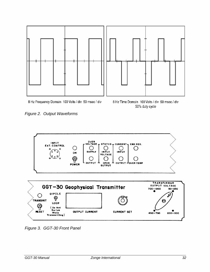
Figure 2. Output Waveforms
Figure 3. GGT-30 Front Panel
Figure 4. Board 214
Figure 5. Board 99
Figure 6. IGBT, Diode, SCR Illustrations
Figure 7. IGBT Drive Waveform (+15V / -10V)
Figure 8. GGT-30, Control Panel Side
Figure 9. GGT-30, Power Side
Figure 10. GGT-30, Transmitter Front Panel Lamp Functions
Figure 11. no figure - reserved
Figure 12. Board 93e: Drive Board
Figure 13. Board 131a: Phase Control and Protection
Figure 14. SCR Driver Waveform 38.4 KHz Burst
Figure 15. SCR Drive Waveform Sequence
Figure 16. Voltage across SCR and Gate Drive, 400V, 8.0A
Figure 17. Voltage across SCR and Gate Drive, 150V, 2.7A
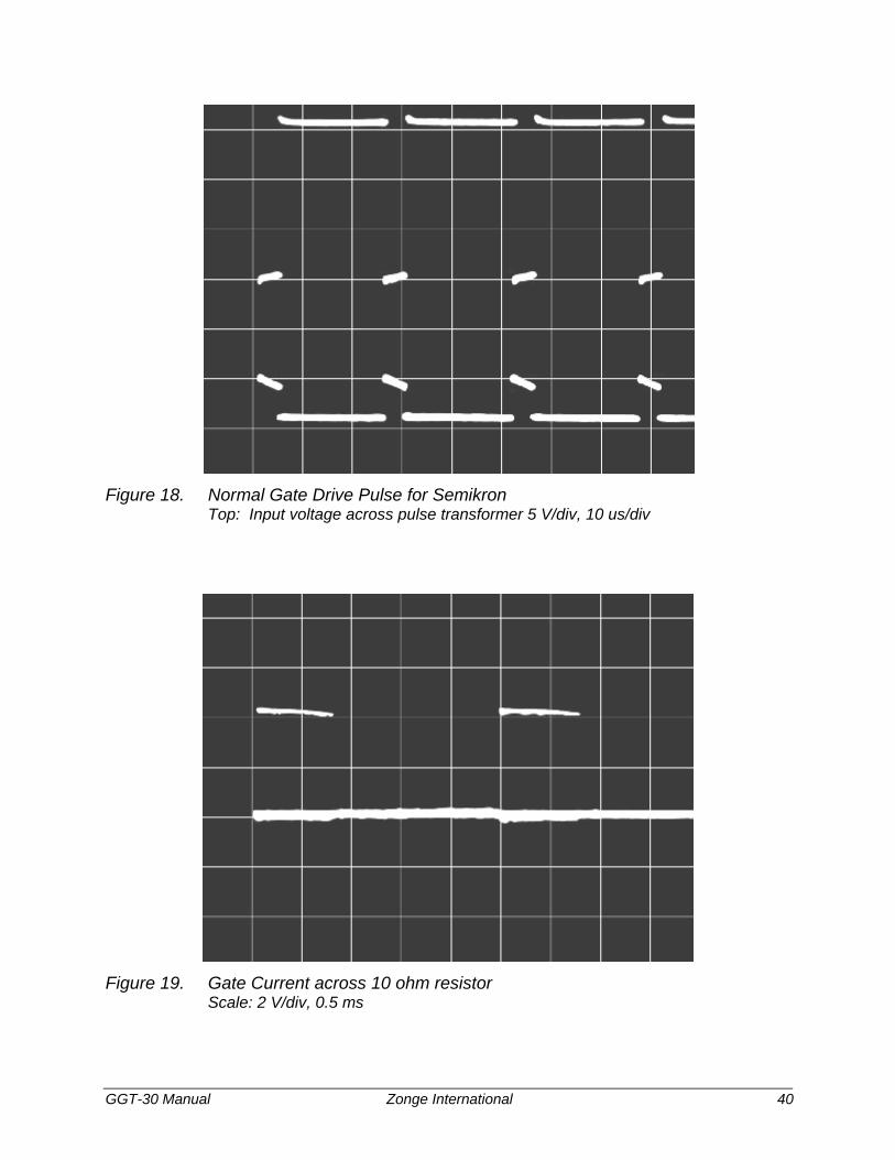
Figure 18. Normal Gate Drive Pulse for Semikron
Figure 19. Gate Current across 10 ohm resistor
Figure 20. Gate Drive
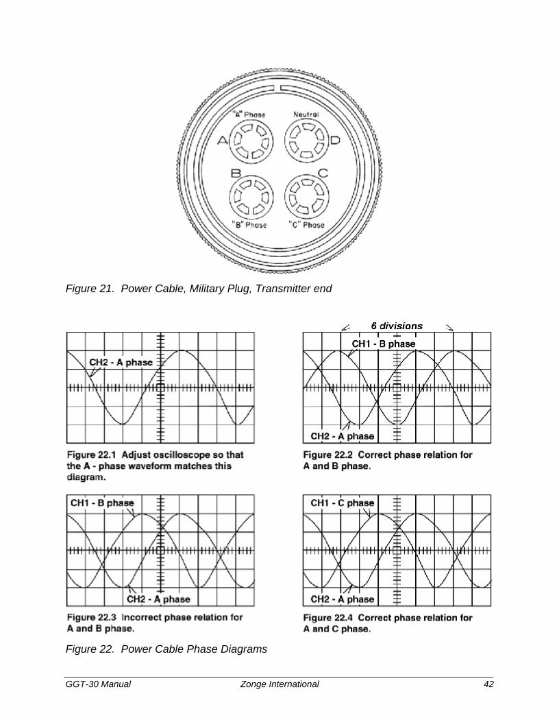
Figure 21. Power Cable, Military Plug, Transmitter end
Figure 22. Power Cable Phase Diagrams
Figure 23. GGT-30, SCR Wiring Diagram - Heatsink
Figure 24. GGT-30, IGBT Wiring Diagram - Heatsink
Figure 25. GGT-30, Major Boards and Components
Figure 26. GGT-30, Chassis Wiring – (pre IGBT)

GGT-30 Manual Zonge International 5
1. INTRODUCTION
This manual is intended to provide the information necessary to operate the GGT-30 and keep it in proper operating condition. It also provides the information necessary to repair the most common transmitter problems.
Section 2 deals with the specifications for the GGT-30 and presents the curves for safe areas of operation. These curves should be observed at all times since operation outside these areas causes immediate component damage.
Section 3 deals with the instructions and procedures needed to operate the GGT-30 in the field.
Section 4 covers the theory of operation of the GGT-30 and contains valuable information should troubleshooting become necessary.
Section 5 covers information necessary to troubleshoot the GGT-30 properly in the field. The troubleshooting and repair steps cover those that are possible in the field. The intent of this guide is to provide the operator with a set of explicit instructions for testing the major features of each board so that the operator can determine if repair in the field is possible, if specific boards or modules must be replaced, or if the GGT-30 must be returned to a Zonge service center.
GGT-30 Manual Zonge International 6
2. GGT-30 SPECIFICATIONS
2.1. Electrical
Input: 120/208 Volts 3-phase 400-cycle
All input power goes through a 3-phase contactor for power shut down.
Standby Power: 100 VA
Power connector: MIL SPEC Screw type
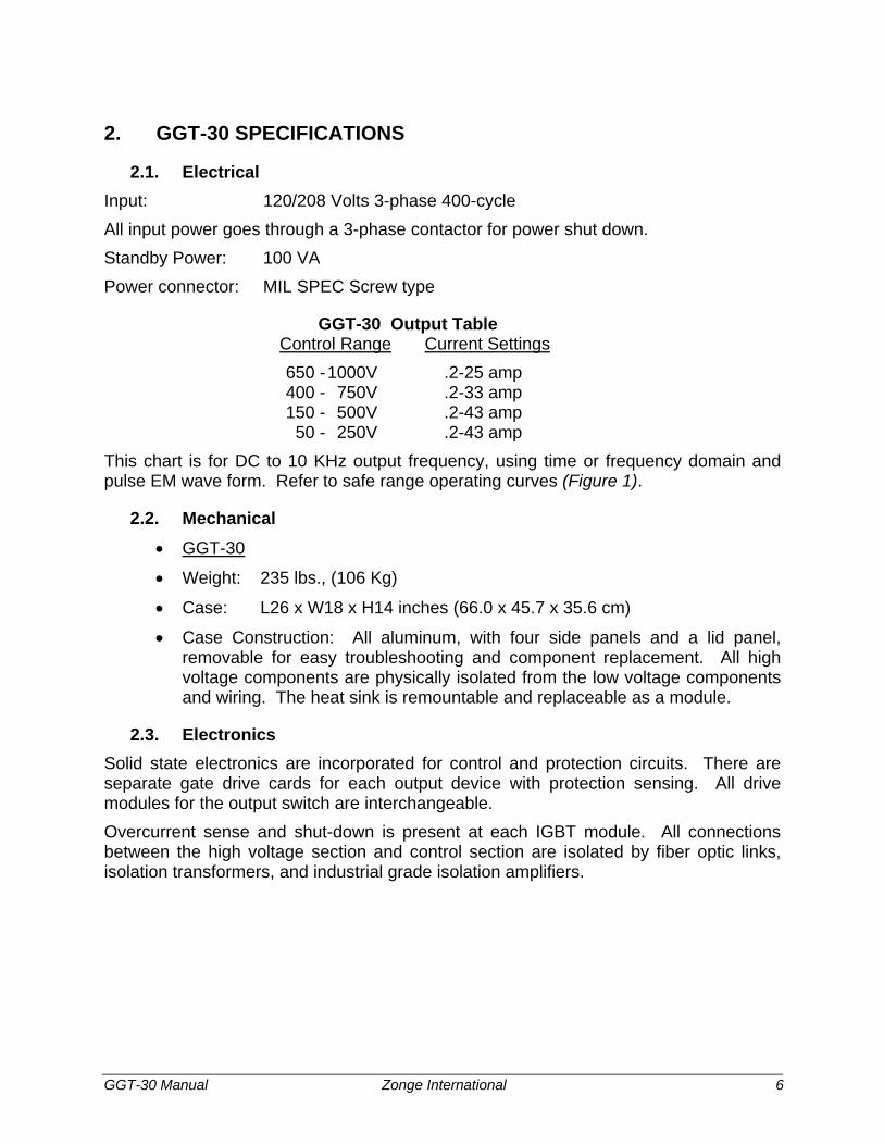
GGT-30 Output Table Control Range Current Settings
650 - 1000V .2-25 amp 400 - 750V .2-33 amp 150 - 500V .2-43 amp 50 - 250V .2-43 amp
This chart is for DC to 10 KHz output frequency, using time or frequency domain and pulse EM wave form. Refer to safe range operating curves (Figure 1).
2.2. Mechanical
GGT-30
Weight: 235 lbs., (106 Kg)
Case: L26 x W18 x H14 inches (66.0 x 45.7 x 35.6 cm)
Case Construction: All aluminum, with four side panels and a lid panel, removable for easy troubleshooting and component replacement. All high voltage components are physically isolated from the low voltage components and wiring. The heat sink is remountable and replaceable as a module.
2.3. Electronics
Solid state electronics are incorporated for control and protection circuits. There are separate gate drive cards for each output device with protection sensing. All drive modules for the output switch are interchangeable.
Overcurrent sense and shut-down is present at each IGBT module. All connections between the high voltage section and control section are isolated by fiber optic links, isolation transformers, and industrial grade isolation amplifiers.
GGT-30 Manual Zonge International 7
2.4. Front Panel Controls
Meters: Digital LCD and Analog
Input voltage Meters (Analog): 0 to 150 volts
Output Voltage (Analog): 0 to 1000 volts
Output Current (Digital): 0 to 199.99 amps
2.5. Controls
POWER ON/OFF: Logic power control. Power is applied to the IGBT drivers when the AC meter shows voltage. The main AC contactor will open for fault conditions, isolating the equipment in case of an emergency. When going to transmit, the contactor closes, and power will ramp up to preset level.
TRANSMIT/RESET: Reset the transmitter; During the next two seconds, start transmit.
VOLTAGE TAPS: 1000, 750, 500, and 250. These are chosen for best efficiency for ground loading. The output current is adjustable from 0.2 to 100 percent of full scale. See Output Table, Section 2.1.
CURRENT CONTROL: Current is adjusted with a 10-turn potentiometer.
LOOP/DIPOLE SWITCH: Select damping resistor for Time Domain loops.
METER DISPLAY SWITCH: Switch meter display between Current, Decay Time, Temperature, Transformer, and Input Power in Kilowatts.
2.6. External Control
Frequency and duty cycle are controlled by an external controller. A 20ma current loop is used to control the logic. It is isolated from the rest of the system by a fiber optic link connecting the input plug to the control board.
The controller manufactured by Zonge is capable of time or frequency domain operation. In time domain, duty cycles of 50% may be selected; in frequency domain, any 16 consecutive, binary-interval frequencies in the range of 1/1024 Hz to 10 KHz may be selected. The controller is isolated from the transmitter by an optical coupler link. Custom controller units that will match the transmitter to most other well-known geophysical systems, can be supplied with the transmitter.

GGT-30 Manual Zonge International 8
3. OPERATING INSTRUCTIONS
3.1. First Time Operation
3.1.1. Inspection
Inspect the transmitter on arrival for any damage that may have occurred during shipment. Remove the transmitter from its case and inspect the printed circuit cards for damage. Also check for connectors and cables that may have come loose during shipment. If any damage has occurred, it should be reported to the shipper and to Zonge immediately and corrected before operation is attempted.
3.1.2. Preparatory Set-up
Set the controls as follows:
CONTROL POWER OFF OUTPUT VOLTAGE 250 VOLTS CURRENT SET 0.1 (must be >0, otherwise Open Output trip)
Connect a 100 ohm resistive load (dummy load - Zonge Model #LB2500) to the red and black output jacks on the transmitter.
Connect a 3-phase power source (120/208 volts-400 Hz) to the transmitter power input. (See Section 3.2 for operation of the ZMG-series motor generators.) The pins on this connector are labeled A, B, C, and D. D is the neutral input. Pins A, B, and C are the A-phase, B-phase, and C-phase respectively. C lags B by 120 degrees, and B lags A by 120 degrees. This is important for proper operation of the GGT-30. If in doubt, refer to the APPENDIX, Checking Phase Sequence - Alternator.
Note: Input voltage for GGT-30 has been optimized for 115/200 V although all of our engine/generator sets are specified as 120/208 V. This has been done to ensure a broader operating range of input voltages for full output.
Connect a battery powered or line isolated oscilloscope to the CAL output jacks on the transmitter. CAUTION: FAILURE TO USE AN ISOLATED OSCILLOSCOPE CAN CAUSE A SHOCK HAZARD AND MAY DAMAGE THE OSCILLOSCOPE. Set up the oscilloscope as follows:
0.5 mSec/division 0.5 volt/division
Connect a transmitter controller to external control (XMT-32 or GDP-32) and set the frequency to 8 Hz and frequency domain.
Turn on CONTROL POWER. The green power indicator should be on. All lamps should light with the automatic lamp test. Toggle the TRANSMIT/RESET switch to RESET. All fault indicator lights should be off, except for END REG and INPUT VOLTAGE. If other fault lights are on, check for loose cables and that the current is set to a value greater than zero. If the cables are not loose, the transmitter has been damaged in shipment and the failure should be reported to Zonge for corrective action.
GGT-30 Manual Zonge International 9
To test for burned out or damaged lights, turn off control power and turn back on after ten seconds. This will cause all lamps to turn on.
Replace any burned-out bulbs by unscrewing the lens and placing a new bulb in the socket. All lamps are 5-volt bulbs except for the 24-volt TRANSMIT bulb.
Toggle the TRANSMIT/RESET switch to RESET and then immediately to TRANSMIT See Section 3.3.1. Do not hold TRANSMIT in the TRANSMIT position. Release the switch immediately after going to TRANSMIT. Adjust the current control knob to 2 amps output current.
The FREQUENCY/TIME DOMAIN switch on the transmitter controller can be toggled between either position. Refer to the oscilloscope trace (Figure 2). Note: Do not toggle this switch when transmitting, when the LOOP/DIPOLE switch is on LOOP, or the fuse will blow on the loop switch circuitry.
If the transmitter fails to operate properly, contact Zonge for possible corrective action.
3.2. Motor-Generator Hook-up Procedure (ZMG-Series)
Disconnect the MG trailer from the towing vehicle and level the unit as much as possible to permit normal oil circulation in the motor. Skid-mounted MG sets should be placed on level ground.
Remove the motor tarp and generator cover.
Check the oil level with the dipstick. Add oil if necessary.
Check the belt tension (belts should deflect at least 1 to 2 inches [2 to 5 cm] at the center of the belt but should not deflect over 4 inches [10 cm]).
Check all nuts, bolts and wires visually. Tighten any loose components.
Place the Voltage Regulator (VR) on the ground on the generator cover, for electrical isolation and protection of the VR. Connect the VR to the alternator using the proper cable. Place the VR out of the way and in the shade if possible. Under the trailer is a good place; it can't be tripped over, is in the shade and will be convenient to operate. Make sure the VR is turned off.
Connect the power cable between the Motor/Generator (MG) and the transmitter. Route the cable on the ground, out of standing water, and out of the way. It is not recommended procedure to leave the cable where it can be tripped over. When tightening the military-style connectors, screw the threaded sleeve until it is tight, then push and wiggle the connector to confirm the sleeve is as tight as possible. Do this with the connector on the GGT-30 as well as the connector on the MG.
Once the MG has been checked out it may be started. To start the engine if the motor is cold, pull the choke out from the control panel. Turn the ON-START switch to START. The electric starter should crank the motor and it should start within 30 seconds. If it doesn't, refer to the appropriate manufacturer's literature. Once the motor has started, allow it to idle for about five minutes. The choke should only be needed for a few seconds unless the weather is very cold or damp.
GGT-30 Manual Zonge International 10
Once the ZMG is warmed up, the engine speed can be increased to approximately 3600 RPM by pulling the throttle lever to the right, and the alternator may be put into use. Refer to the Voltage Regulator Manual for complete instructions and troubleshooting procedures.
Turn the voltage regulator on and depress the START button on the voltage regulator holding it down MOMENTARILY until the alternator is working. Holding the button down too long can damage the alternator, the alternator cooling fans, the GGT cooling fans, or VR circuitry.
Confirm that the cooling fan on the alternator is running. Operation under load without the cooling fan will rapidly damage the alternator by overheating it.
Adjust the engine speed to produce an AC frequency between 400 and 425 Hz. Adjust the VOLTAGE ADJUST for 115 volts. See the Voltage Regulator Manual for complete instructions.
3.3. Description of Controls
Description of controls (Figure 3).
3.3.1. RESET / TRANSMIT switch
The RESET / TRANSMIT switch resets all of the internal circuitry in the GGT-30. The GGT-30 cannot be made to transmit until a valid RESET is given. After RESET is activated the operator has a two second time-out period during which a valid TRANSMIT can be given. If TRANSMIT is not activated during this two second period another RESET must be given. This ensures proper sequencing of the internal circuitry.
3.3.2. TRANSMIT light
The TRANSMIT light indicates that the GGT-30 is transmitting and that high voltage is present on the output. It is connected across the safety power contactor and will go off when a fault or reset occurs that opens the contactor.
3.3.3. SUPPLY OVERVOLTAGE light The SUPPLY OVERVOLTAGE light indicates that the voltage level on the supply to the output switch has exceeded the safe operating level of 1000 volts. This can be caused by driving a large capacitive load, or by running with an input voltage from the alternator of more than 115 volts, while using the 1000 volt tap on the TRANSFORMER OUTPUT VOLTAGE switch.
3.3.4. OUTPUT OVERVOLTAGE light
The OUTPUT OVERVOLTAGE light indicates that the voltage level on the output has exceeded 1000 volts. This can indicate that a largely inductive load is present on the output.

GGT-30 Manual Zonge International 11
3.3.5. INPUT VOLTAGE light
The INPUT VOLTAGE light indicates that the voltage level from the alternator exceeded 130 volts or was less than 95 volts and must be adjusted into the proper range, preferably 115 volts.
This GGT transmitter operates slightly differently from older transmitters. The new sensor monitors phase_loss, over_voltage, and phase_reversal. It will indicate on the input voltage status light when the transmitter is transmitting.
The following conditions will cause this light to illuminate:
Loss of phase – for example: fuse blown, alternator failure, cable failure.
Phase reversal – alternator was disassembled and rewired incorrectly.
Input over voltage – input voltage greater than 30 V and a small phase imbalance is present. Note: If input voltage exceeds 135 V on A-phase, the transmitter output will shut down until voltage drops.
The sensor not active until transmitting, since it is after the contactor and main power fuses. However, the status lamp will be on until transmitting.
3.3.6. OPEN CIRCUIT light
The OPEN CIRCUIT light indicates that the output circuit is open and the transmitter is trying to transmit into an infinite load. NOTE: the GGT-30 will not transmit if the Current Control is set to zero.
3.3.7. INPUT OVERCURRENT light
The INPUT OVERCURRENT light indicates that too much current has been requested from the supply generator. The detection level is 83.3 amps and is set at the factory.
3.3.8. OUTPUT OVERCURRENT light
The OUTPUT OVERCURRENT light indicates an overcurrent condition in one of the output IGBT modules. If this lamp will not reset it indicates that an IGBT module has been damaged. Refer to the troubleshooting section. The detection level is set at desaturation of the IGBT’s. It is not adjustable.
3.3.9. END REG. light
The END REG. light indicates that the transmitter is not able to supply the amount of current desired. Either the current must be lowered or the TRANSFORMER OUTPUT VOLTAGE tap switch must be set to a higher voltage. It will also come on when the output current is set too low, showing an unregulated condition.
3.3.10. OVERTEMP light
The OVERTEMP light indicates that a temperature of 85 deg. C has been reached on the phase control SCR's. Stop transmitting and allow the transmitter to cool.
GGT-30 Manual Zonge International 12
3.3.11. TRANSFORMER OUTPUT VOLTAGE tap switch
The TRANSFORMER OUTPUT VOLTAGE tap switch selects the output voltage range of the transformer and sets operation over the range described in the Output Table in Section 2.1.
3.3.12. LOGIC SUPPLY circuit breaker
The LOGIC SUPPLY circuit breaker is a push-to-reset circuit breaker for the logic power supply (+5, +15, -15). If the button is held down during an overcurrent situation, the breaker will still open. This is a safety feature connected to A phase.
3.3.13. DRIVE SUPPLY circuit breaker.
The DRIVE SUPPLY circuit breaker is a push-to-reset circuit breaker for the four drive power supplies for the IGBT drive modules. It is connected to B phase and powered up whenever power is connected to the transmitter.
3.3.14. DIPOLE/LOOP switch
This switch is used to turn the loop-damping circuits on and off. It should be in LOOP position only for TEM operation. The loop switch will be damaged if it is switched while transmitting.
3.3.15. METER SELECT switch
This push button selects the following meter functions:
OUTPUT CURRENT – output current from 10 ma to 25 amps.
DECAY TIME – in microseconds, time for transmitter to turn off into a loop.
TEMPERATURE – in degrees Celsius – transformer temperature.
INPUT POWER – input power to transmitter in Kilowatts, from motor generator. Use to adjust output power to match generator size.
GGT-30 Manual Zonge International 13
4. THEORY OF OPERATION
4.1. Board 214
Board 214 (Figure 4) accepts drive control signals from Board 93 and uses these to control the turn-on and turn-off of the IGBT’s. Each board has its own transformer and power supply. This is because the ground on Board 214 is connected to the emitter of the IGBT and needs to be isolated during operation
This board has a dual supply that generates +15, -10 volts for the IGBT driver M57959L that provides drive and protection to the IGBT module. It generates a fault condition if the IGBT comes out of saturation during a current fault. There is a pair of fiber optic devices, a transmitter and a receiver to control the drive module switching and fault generation. These provide high voltage isolation between the four drive boards. All four Board 214’s must be isolated from each other for proper operation of the transmitter.
4.2. Board 93
There is a test switch located on Board 93 (Figure 12) for ease of troubleshooting. This switch must be in the RUN position for normal operation. When in a test position, this switch provides either a 4 Hz or 1024 Hz drive signal.
When RESET is activated, one of the 4538 ICs generates a two-microsecond reset pulse which goes to all of the protection latches. RESET also goes to a second 4538 that is used as a two-second timer. The purpose of this circuitry is to ensure that the transmitter cannot transmit before a valid RESET is generated. After RESET is activated the operator has two seconds to activate TRANSMIT. If TRANSMIT is not activated within two seconds, another RESET is required initiate transmitting.
When TRANSMIT is activated during the two second time-out, one half of a 74C74 latches the contactor relay driver. A fault condition will reset the contactor latch and remove power from the transformer and drive to the IGBT’s.
The deadtime circuitry is set for a one to two microsecond deadtime that is used to gate-out overcurrent detection during switching. It is generated by a 4520, 74C74, and a 4 MHz oscillator. One half of the 4520 is held in a reset state while the other half is counting. When reset on the 4520 is removed it counts eight oscillator cycles before triggering one half of the 74C74, and causes a drive signal to be generated. Loss of the oscillator prevents the drive signal from being generated.
Overcurrent is latched on this board. The fiber optic signal for overcurrent is active-low or off. This ensures that the loss of a cable will protect the drive cards and prevent drive signals from being generated. Four latched indicators are included on the board to help determine the exact source of the overcurrent situation. These correspond to the IGBT modules on the heat sink. Overvoltage is latched on this board and the signal is active-high or on.
GGT-30 Manual Zonge International 14
4.3. Board 131
Board 131 (Figure 13) regulates the output current of the transmitter. This board provides the drive to the controlled bridge rectifier, feedback control of the bridge, plus inhibit and protection functions during faults. Its main function is to maintain a constant current at the output of the transmitter for varying loads.
Due to the harmonic noise generated by the phase control of the output voltage, the primary waveform from the alternator is distorted from a pure sine wave. In order to minimize the noise on the reference signal, an active filter is used to remove the higher harmonics. The active filter is set for a phase shift of 60 degrees at 400 Hz. This is compensated for in the control circuitry. The filter provides the reference waveform for all of the control circuits. The output of the filter is sent to the phase lock loop.
The phase lock loop circuit (4046) is used to multiply the 400 Hz signal to a higher value that is then divided by two divider chains, one that divides by 768 and the other that divides by 128. These give outputs of 400 Hz and 2400 Hz respectively from a master frequency of 307.2 KHz. The 2400 Hz signal is used by the ring counter to clock the data that comes from the main comparator. This provides the equidistant pulses used to fire the controlled bridge SCRs. The 400 Hz output of the other divider chain is fed back to the 4046 phase lock loop. It is this phase reference that is compared with the input waveform. This keeps the multiplied signal phase locked to the input frequency. Due to the large capture ratio of the system, the phase locked loop can remain in lock over a large range of frequencies. After power up on the system, it may take a second or so for the phase lock loop to lock in. After it locks in, it should remain so for all conditions except a complete loss of power.
The main comparator provides updated information on the output current to the firing circuits. It provides the reset pulses for the ring counter. The comparator switches its output in reference to the DC level of the control voltage as compared to the full wave rectified sine wave. The switching point provides the timing for the firing angle of the SCRs. Maximum firing angle is reached when the control voltage is equal to the peak of the reference sine wave while the converse is true when the control voltage is at zero. During normal regulation, the control voltage will increase and decrease as needed to maintain a constant output current.
The main comparator provides updated information on the output current to the firing circuits. It provides the reset pulses for the ring counter. The comparator switches its output in reference to the DC level of the control voltage as compared to the full wave rectified sine wave. The switching point provides the timing for the firing angle of the SCRs. Maximum firing angle is reached when the control voltage is equal to the peak of the reference sine wave while the converse is true when the control voltage is at zero. During normal regulation, the control voltage will increase and decrease as needed to maintain a constant output current.
GGT-30 Manual Zonge International 15
The next section covers the control and protection circuitry of Board 131. There are two divisions to this section, one that covers the current feedback loop and the other that provides protection from faults in the system.
4.3.1. Current Regulation
This is composed of the following sections: current setpoint, slow turn-on, isolated current sensing, and integration of the current setpoint with current feedback.
4.3.1.1. Current Setpoint
Current control is accomplished by sensing a control voltage that is buffered by an amplifier controlling the offset of the integrator's negative input. This voltage sets the point at which the integrator output is equal to the voltage required to maintain a steady state current in the feedback loop.
4.3.1.2. Current Feedback
The transmitted current is sensed across a 0.1 ohm resistor, then sent through a true RMS (Root Mean Square) device (AD536), a sample-hold device and an isolation amplifer. This provides a DC representation of the output with noise and ripple being averaged out. The output of the isolation amplifier is sent to both the integrator and the digital voltage meter through buffer amplifiers.
4.3.1.3. Transmit, Soft Turn-on
Two other devices tie onto the positive integrator-summing junction. These are used in transmitter turn-on and fault control. Soft turn-on is provided by the 74C908. It does this by holding the integrator in an off condition until turn-on. Due to the integration time constant, power is applied at a controlled rate. Also, the 74C908 forces the positive input of the integrator to be high in a fault or rest condition.
4.3.1.4. Fault Detection
The board can sense various out-of-range levels and act accordingly. There are provisions for alternator undervoltage and overvoltage, end of regulation, open circuit, and input overcurrent.
Alternator under/overvoltage is sensed by the true RMS converter and scaled to be proportional to the input voltage. If it exceeds the preset value, the alternator overvoltage lamp will light and the board will shut down until the voltage reaches a safe value. This is not a latched condition.
End of regulation also uses the alternator voltage and senses when there is not enough voltage to maintain regulation by comparing the alternator voltage to the control voltage. A lamp will light for this condition but no shutdown takes place.
Input overcurrent sensing is provided to detect overcurrent on the input supply. This is accomplished by sensing the input supply current through a current transformer, converting this to the RMS value of the input current, and then applying the DC signal to a comparator that is set to trip when the current exceeds 83 amps on supply A-phase. This resets the transmitter switch, shutting off the transmitter.
GGT-30 Manual Zonge International 16
Open Circuit detection also uses this circuitry to detect when the transmitter should be transmitting but no current is being output. Both circuits latch and indicate their condition on front panel lamps.
4.3.1.5. Board 99: Output Pulse Amplifiers DANGER: HIGH VOLTAGE
Board 99 (Figure 5) contains the pulse amplifiers and transformers. As long as inhibit is high, the gate drive will output to the drive amplifiers with the modulation signal impressed on it. This signal drives the 2N5336 transistors that drive the pulse transformers. The pulse transformers drive the SCRs and provide isolation between the SCRs and the control board. By using high frequency modulation, an efficient transformer can be used and a lower average current in the pulse transistors is maintained. Refer to waveforms in Figures 16-20.
4.3.1.6. Boards 175, 176: Meter Circuits
The current meter also has different functions that receive signals from Board 131. The input power is measured and calculated with a multiplier circuit AD633 from the input current and input voltage that are the true RMS values used for input overcurrent and input voltage. This voltage along with the output current and the digital period and duty cycle are sent to the meter Boards 175 and 176.

GGT-30 Manual Zonge International 17
5. TROUBLE-SHOOTING PROCEDURES
5.1. High Voltage Areas
Dangerous voltages are present throughout the transmitter. The following is a list of most but not all of the areas where caution should be exercised (Figure 25).
3-phase 115 VAC input at contactor, line fuses, power supply, Board 99, high-voltage transformer, IGBT drive transformers and output circuits.
All heat sinks can vary from ground potential to 1000 volts.
All boards numbered 214. These float along with the transmitter output and can have 1000 volts at whatever frequency is being transmitted.
The voltage-tap switch, phase-control SCR's, filter choke, supply capacitors, protection choke, and protection diode.
The metal chassis is connected to the AC generator neutral line and should not under normal operating conditions carry high voltage. For safety, it is normal to ground the transmitter chassis to a stake well away from any transmitter electrodes.
All four output terminals are naturally dangerous at all times. When the transmitter is turned off, it takes approximately five seconds for the bleeder resistor to discharge the capacitor completely. It is good practice to touch only one output terminal at a time while keeping your other hand in your back pocket, even when the transmitter is turned off.
5.2. Disassembly
The top panel may be removed by unlocking the twelve quarter-turn fasteners. This panel provides access to the heat sink plate on which the IGBT transistors and diode modules are mounted. The complete plate may be removed by disconnecting the wiring from the terminal block, providing access to the capacitor and choke tray. Access to the rest of the GGT-30 is accomplished in a similar manner by unlocking the quarter-turn fasteners and removing the side panels. When the side panels are removed, dangerous high voltages are exposed whenever power is applied to the transmitter. The GGT-30 should never be opened at frequencies above 256 Hz for any length of time when it is out of the case because proper cooling will not occur.
Remove side panels below the controls and meter for access to boards 93, 131, and SCR’s.
Remove back panels to access board 214.
5.3. (reserved)
5.4. Board 214 – Insulated Gate Bipolar Transistor (IGBT) Drive
Board 214 (Figure 4) can be tested by connecting a 115/200 VAC-400 Hz motor-generator to the transmitter input military connector. Pin B is the B-phase input and

GGT-30 Manual Zonge International 18
provides power for the internal power supplies on these boards. Pin D is the transmitter neutral.
Disconnect the external control source as the internal timing is connected to the single yellow wire used for most of the tests on this board. Disconnect the contactor relay by disconnecting the molex plug at Board 93. NOTE: IT IS VERY IMPORTANT THAT THE CONTACTOR BE DISCONNECTED SO THAT HIGH VOLTAGE WILL NOT BE PRESENT ON THE IGBT MODULE DURING TESTING. Follow the procedure below to determine if the fault lies with this board or with some other part in the transmitter. NOTE: ALL RESISTANCE MEASUREMENTS SHOULD BE MADE WITH THE TRANSMITTER TURNED OFF.
5.4.1. Verify first that Board 93 is working since its proper operation is essential to proper operation of these IGBT drive boards. See Section 5.5.
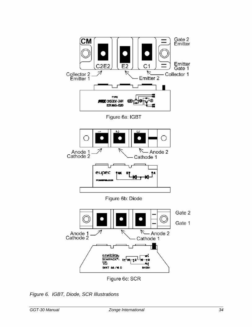
5.4.2. A fault light that cannot be RESET is a good indication of an IGBT or Board 214 failure. Disconnect the molex connector lead to the IGBT module suspected to be failing and then follow the procedure below using a Fluke or similar digital voltmeter. The "from" point uses the ground lead on the Fluke and the "to" point uses the positive lead of the Fluke. All resistance measurements are made with the transmitter turned off. Probe placement is illustrated in Figure 6.
5.4.3. Measure the resistance from emitter to collector of the IGBT (Figures 6a and 24). The test point is the disconnected molex connector. This reading should be approximately 500 ohms, with a high value diode function meter. Using other meters with low ohms the value may be 30 Kohms or 0.35 volts in diode mode. If not, go to Section 5.4.9.
5.4.4. Measure the resistance from collector to emitter. This reading should be infinite. If not, go to Section 5.4.9.
NOTE – THE FOLLOWING SHOULD BE DONE ONLY IN A NON-STATIC ENVIRONMENT
------------------- GATES ARE SENSITIVE TO STATIC ELECTRICITY --------------------
5.4.5. Measure the resistance from gate to collector and from gate to emitter. The gate test point is the molex connector. These readings should be infinite. If not, go to Section 5.4.9.
5.4.6. Measure the resistance from collector to gate. This reading should be infinite. If this reading indicates a short or resistance, go to Section 5.4.9.
5.4.7. Measure the resistance from emitter to gate. This reading should be infinite. If this reading indicates a short or resistance, go to Section 5.4.9.
5.4.8. If the IGBT has tested okay, go to Section 5.4.11 to test Board 214.
GGT-30 Manual Zonge International 19
5.4.9. Replace the IGBT. Disconnect the gate leads at Board 214 by disconnecting the molex connector (Figure 24). Remove the two screws in the base of the IGBT and remove it from the heat sink (Figure 6). Reverse this process to install the replacement IGBT. Avoid excessive torque on the two screws in the base of the IGBT to prevent stripping these holes. The IGBT module is equivalent of two IGBT’s and two diodes. Be very careful to connect gate leads to proper connections on module.
5.4.10. Whenever an IGBT fails it is possible that another one has also failed. Check the other IGBT’s using the previous procedure. Next, it is essential that the quenching diode, DD31S-1400, around the protection inductor on the heat sink module be tested. If this diode has shorted, then the overcurrent protection will not work and more IGBT’s will be lost if another short occurs. If this diode has opened, then the output will be unstable and will cause either OVERVOLTAGE indications or IGBT failure. Test this diode by removing its cathode lead and measuring it with a Fluke or similar digital voltmeter on the lowest diode range (2k). Anode to cathode resistance should be infinite. Cathode to anode should be in the range of 500 - 800 ohms. If the diode is bad replace it. Test all the quenching diodes using the previous procedure.
5.4.11. Turn on the transmitter. Reset the transmit switch and make sure all lamps are out. Check for -10 volts between gate lead and cathode on Board 214's. If present go to Section 5.4.13. If not present continue with Section 5.4.12.
5.4.12. Check the circuit breaker and if it has tripped, reset it and recheck for 115 VAC input at each module. If 115 VAC is still not present check for wiring problems or problems with the power source. Correct the problem and go to 5.4.13. If the modules continue to trip the circuit breaker, determine which module is responsible and replace it.
5.4.13. Check the +15 volt supply at the output of the 340-15. This should be within 1/2 volt of 15 volts. If this supply is within this limit, go to 5.4.16.
5.4.14. Check the input to the positive regulator (340-15) from the bridge rectifier. This should be approximately +20 volts but will vary according to the input source voltage. If the input is not +20 volts, check D2, C4 and the output of the transformer. Correct the problem and go to 5.4.13.
5.4.15. If the input to the regulator is correct but the output is not, then check the drive device for shorts (57959) or the five volt regulator. Correct the problem and go to 5.4.13.
5.4.16. Check the -10 volt supply at the output of the negative regulator (337). This should be within 1/2 volt of 10 volts. If the supply is within this limit, go to 5.4.19.

GGT-30 Manual Zonge International 20
5.4.17. Check the input to the negative regulator (337) from the bridge rectifier. This should be approximately -20 volts but will vary according to the input source voltage. If the input is not -20 volts, check D5, C8 and the output of the transformer. Correct the problem and go to 5.4.16.
5.4.18. If the input to the regulator is correct but the output is not, then check the regulator and the IC (57959) for a failure. Correct the problem and go to 5.4.16.
5.4.19. Check the 5 volt regulator (78L05). Use the ground reference. If the regulator is putting out 5 volts +/- 0.5 volts, go to 5.4.20. If the regulator is failing, replace it and recheck the output. If it still appears to be failing, then the optical receiver supplying it is bad and must be replaced. Correct the problem, then continue.
5.4.20. Plug in all of the cables to the IGBT drive modules and set the test switch on Board 93 for a 256 Hz test signal. Then activate the RESET switch on the transmitter after applying power to the unit. All of the fault lights should be out. If not, go to 5.4.2 before proceeding any further. The fault light will indicate a failing module but others may also be failing and can be checked by performing this same procedure starting at 5.4.2.
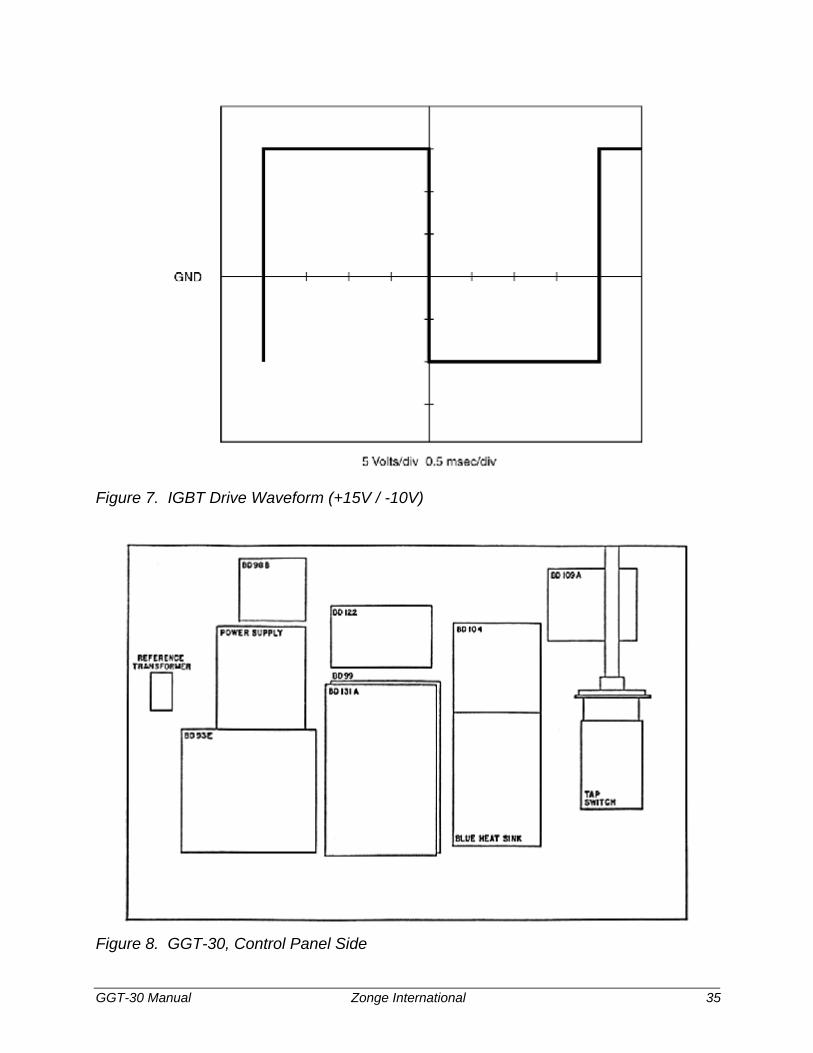
5.4.21. Connect the molex connector on all of the IGBT modules. Attach an oscilloscope to the emitter (ground) lead of Board 214 and the gate output. The output observed on the scope should be a 256Hz square wave of approximately +15 / -10 volts (Figure 7). This should be observed on all four boards. When the square wave is not present or of only one polarity, the board is not driving properly. Go to 5.4.23 in this case. When the proper square wave is observed, connect a 100 ohm 2 watt resistor between gate and emitter (ground). The square wave will diminish in amplitude but should still be present. If the square wave becomes unipolar when the resistor is added, go to 5.4.23.
5.4.22. Reconnect the leads between Board 214 and the IGBT heat sink modules. The output on all modules should look like Figure 7. If not, recheck step 5.4.21 and if the problem is still present go back to 5.4.2 and recheck the IGBT. If the output agrees with Figure 7, Board 214 is working properly. Turn the transmitter off and check diode D4 using a Fluke meter on the diode range. Replace the diode if it is open or shorted. It is recommended to test D4 in this manner because testing it while transmitting without the proper high voltage probe can be hazardous to the operator.
5.4.23. Recheck the power supplies (+15, -10, +5 volts) using steps 5.4.13 to 5.4.19, and correct any power supply problems. Set the test switch on Board 93 to 256 Hz.
GGT-30 Manual Zonge International 21
5.4.24. Connect the scope ground lead to the IGBT emitter. Connect the scope probe to the cathode of 57959 IC. A 256 Hz signal should be visible between +5 volts and not quite ground. If present, go to 5.4.26. If this is not present, check the fiber optic DRIVE cable from Board 93. The light output should be red. Move the test switch on Board 93 to the 1 Hz position. Now the drive signal should alternate on and off at a 1 Hz rate. If there is no drive signal and no fault lights are on, repair Board 93. Board 93 will not produce drive signals when faults are indicated. If fault lights are on and RESET does not clear the fault, go to the troubleshooting procedure for Board 93. If the fiber optic drive is working and the signal at the fiber optic output is incorrect as tested above, then continue.
5.4.25. Note: the IGBT devices will output an overcurrent fault whenever they are disconnected from Board 214. This makes it difficult to determine which module is bad. The best method is to replace any module that has various results during tests.
5.4.26. Observe the light output of the gray optical transmitter. When the IGBT module is connected to Board 214, the light should be on, and when disconnected it should be dim, and flashing at a high rate. If it does this, the current sense circuitry is working properly. Go to 5.4.20 and recheck.

GGT-30 Manual Zonge International 22
5.5. Board 93 - Output Switch Control
Board 93 (Figure 12) can be tested by connecting the transmitter to a motor generator. Pin A is the A-phase input and provides power for the internal power supplies for this board and the IGBT driver modules. Pin D is the transmitter neutral and is connected internally to the transmitter chassis. Therefore, an isolation transformer is needed on the oscilloscope. Disconnect the external drive source as the internal timing is used for most of the tests on this board. Disconnect the contactor relay by disconnecting the molex plug by the contactor. NOTE: IT IS VERY IMPORTANT THAT THE CONTACTOR BE DISCONNECTED SO THAT HIGH VOLTAGE WILL NOT BE PRESENT ON THE OUTPUT DURING TESTING.
Follow the procedure below to determine if the fault lies with this board or with some other part in the transmitter.
NOTE: ALL RESISTANCE MEASUREMENTS SHOULD BE MADE WITH THE TRANSMITTER TURNED OFF. DISCONNECT CONTACTOR CONTROL WIRE FROM BOARD 93 (YELLOW WIRE WITH THE SINGLE MOLEX CONNECTOR) WHEN DOING ANY MEASUREMENTS ON THE TRANSMITTER THAT DO NOT REQUIRE OUTPUT. Check SV power to board.
5.5.1. Push "RESET".
5.5.2. If the OVERVOLTAGE lights are still on, go to 5.5.15.
5.5.3. If the OVERCURRENT lights are still on, go to 5.5.17.
5.5.4. Set the test switch on this board to the 1 Hz position and pull all of the fiber-optic cables labeled DRIVE (Figure 12). These connectors are gray. Observe the lights (LEDs) in the four optical drivers. DRIVE1 and DRIVE2 should be alternating with DRIVE3 and DRIVE4 at 1 Hz. If this is not occurring, go to 5.5.8.
5.5.5. Set the test switch to the RUN position and attach the external controller. Set the frequency to 1 Hz and again observe the output from the four optical drivers. If they do not alternate, go to 5.5.7.
5.5.6. Reinstall the four drive cables. This board has tested okay.
5.5.7. Check the fiber optic cables from the drive input Board 91 to Board 93 to ensure that all cables are installed properly. If this does not correct the problem, pull the TRANSMITTER DRIVE cable from Board 93 and observe the output from the cable. The light should be alternating on and off. If it is not, the external controller may be off, or malfunctioning, or the input optical driver may be bad. If the output of the cable is alternating on and off, then either the optical receiver is bad or IC C3 is bad. Correct the problem and go to 5.5.5.

GGT-30 Manual Zonge International 23
5.5.8. Using an oscilloscope check for a 4 MHz square wave at pin 1 of IC B5. If there is no signal here, check the five-volt supply to this board and be sure power is on. If power is on and five volts is absent, check the power supply and replace it if necessary. If five volts is present, replace the oscillator and go to 5.5.4.
5.5.9. Check for a 4 Hz drive signal on pins 7 and 15 of IC B5 (4520). If this is not present, make sure that the test switch is in the 1 Hz position. If the 1 Hz drive signal is not present, IC C3 or C4 is bad. Replace the faulty IC, check the drive signal, and go to 5.5.4.
5.5.10. Set the test switch to 1024 Hz. A 1024 Hz square wave should be present at pins 3 and 11 of IC B4. If this square wave is not present, IC B5 is bad and must be replaced. Replace IC B5, check the square wave again, and go to 5.5.4.
5.5.11. Check for a 1024 Hz square wave at pins 5 and 9 of IC B3. If this is not present, replace IC B4 and go to 5.5.4.
5.5.12. Check for a 1024 Hz square wave at output of IC B3. If this is not present, look at the levels on the following pins. Pins 1, 2, 4, 10, 12, and 13 should all be at five volts. If they are not, check for fault lights being on, five volt power supply failure, IC C3 failure or Duty Cycle optical receiver failure. Correct the failure and go to 5.5.4.
5.5.13. Check for a 1024 Hz square wave at pins 3 and 5 of IC B2. If this is not present, either B2 is bad or the optical drivers are bad. Determine which is failing and replace.
5.5.14. Check for an active drive signal light at the output of the optical drivers. If present, go to 5.5.15. If not, go back to 5.5.8 and recheck the signals.
5.5.15. Pull all four of the OVERCURRENT cables from the blue optical receivers labeled PROT1, PROT2, PROT3, and PROT4. This should cause the OVERCURRENT fault lights to come on. Now reinstall the four OVERCURRENT cables and push the RESET switch and observe the fault lights. If the OVERCURRENT fault lights reset, go to Section 5.6. If not, then IC D9 or the OVERVOLTAGE optical receiver is bad; correct this problem and go to 5.5.1. If the OVERCURRENT fault lights stay on, go to 5.5.16.
5.5.16. The tests indicate that either IC D4 or the RESET switch or wiring is bad. Correct the problem with the RESET circuitry and go to 5.5.1.
5.5.17. Pull the OVERCURRENT fault cable associated with the fault light that cannot be reset. If the end of the cable glows red, go to 5.5.19.

GGT-30 Manual Zonge International 24
5.5.18. The IGBT module (Board 214) associated with the unlit cable is failing or has its cable unplugged. Repair the module or plug in the cable and go to 5.5.1.
5.5.19. Pull the other OVERCURRENT cables. The OVERCURRENT fault lights should come on. Reinstall the cables and activate the RESET switch. If the OVERCURRENT lights associated with the cables that were pulled do not go out, go to 5.5.16.
5.5.20. Check the ICs associated with the fault light that cannot be reset which will be either C7, D7, C6, C8 and C9 and the optical receiver associated with the fault light. Repair the problem and go to 5.5.1.

GGT-30 Manual Zonge International 25
5.6. Board 131 - Current Feedback and SCR Drive Signals
Board 131 (Figure 13) can be tested by connecting the transmitter to a 115/200 VAC, 400 Hz motor generator. Pin A is the A-phase input and provides power for this board. Pin D is the transmitter neutral. Disconnect the external drive source as the internal timing is used for most of the tests on this board. Disconnect the contactor relay by disconnecting the molex plug at Board 93. NOTE: IT IS VERY IMPORTANT THAT THE CONTACTOR BE DISCONNECTED SO THAT HIGH VOLTAGE WILL NOT BE PRESENT ON THE IGBT MODULE DURING TESTING. Follow the procedure below to determine if the fault lies with this board or with some other part in the transmitter. NOTE: ALL RESISTANCE MEASUREMENTS SHOULD BE MADE WITH THE TRANSMITTER TURNED OFF.
5.6.1. Power Supply
Verify first that the supply voltages +5 and ±15 are present (see the test points on Board 131, Figure 13). If they are not within 5% unplug Board 100 and recheck the power supply. If the power supply is still not working, notify Zonge as there are no user serviceable parts on the power supply.
5.6.2. Oscilloscope Setup
Set up a Fluke Scope model 123 Oscilloscope or similar battery operated or line isolated oscilloscope as follows:
DC coupled 5.0 volt Range 1 msec/div Channel 2 trigger Ground lead on ground wire
5.6.3. Active Filter
Set input voltage to 120 VAC RMS. Setup procedure for the active filter output - This adjustment must be made before any other setup or checkout procedure can be made. With the scope probe tip on the output of pin 6 of H-4 (OP-5) or the TEST POINT (Figure 13) adjust pot R26 for a 20 VPP (+7.07 VRMS) signal at pin 6 H-4.
5.6.4. Phase lock loop
The phase lock loop (D3) is used to multiply the 400 Hz signal to get a resultant frequency of 307,200 Hz (see Theory Of Operation). Pin 1 on D3 is the in-lock indicator. When the system is in-lock the output of pin 1 of D3 is a 5-volt level signal with a pulse 5.0 microseconds wide going to ground at 2.5 milliseconds intervals. Pin 4 should have a 307,200 Hz square wave with a period of 3.3 microseconds and pin 3 should have a 400 Hz square wave synchronized with pin 14. The output of pin 4 is divided by A3. This results in a 2.4 KHz square wave and a 38.4 KHz signal for gate drive to the SCR drivers. The 307,200 Hz signal is also divided by C3 (4522) and B3 (4520) to 400 Hz that is the feedback to the phase lock loop for phase comparison with

GGT-30 Manual Zonge International 26
the incoming signal. There will be no output from A3 if reset is high. Reset is generated by the positive-going pulse each time the comparator F4 (CMP01) switches.
5.6.5. Current set point reference
To check the output current set point reference G7 (LH0070) use a digital voltmeter set for DC input on the 20 volt range. Check the REF output to the current setpoint potentiometer; for a GGT-30 it should be 2.02 volts +10 mv. Put the probe tip on the set input from the current setpoint potentiometer and adjust the current set potentiometer from 0.0 to 10.0 divisions. The voltage should vary from 0-2 volts. Check the output of H5 (OP5), the current set buffer, for tracking over the same range.
5.6.6. TRANSMIT/RESET Switch
To check the TRANSMIT/RESET switch, put the scope probe on the TEST input or pin 1 E1 (74C30). The signal will be low for RESET and high for TRANSMIT.
Pin 9 of F3 (4038) should give a two second low pulse each time the TRANSMIT/RESET switch is toggled to TRANSMIT. This is the inhibit time for the contactor to pull in. This reduces the transient pulse that occurs when an unloaded transformer is energized.
5.6.7. Fault inhibit
Pin 8 of R1 (74C30) should be low after two seconds when the TRANSMIT/RESET switch is toggled toward TRANSMIT and goes high when the switch is toggled toward RESET. Pin 6 of E2 (74C00) is the inverse. This signal controls the soft start gate and the output gate drive to the SCR bridge. If pin 6 of the E2 does not go high, check the alternator over/under voltage and pin 9 of 74C221 (F3). This should be high for the output of E1 (pin 9) to go low.
5.6.8. Alternator High-Low shut down
This signal also controls the inhibit function. It is generated by the level of the AC voltage from the active filter that feeds H2 (AD536, a true RMS converter). The output should be 10 volts for a 20 volt peak-to-peak AC signal. This is the reference for the transmitter alternator shut-down comparators. G1 and H1 should be high if they are in tolerance for correct alternator input voltage (see setup procedure for correct voltages on shut down), i.e. 90 volts for low shut down and 130 volts for high shut down.
If the outputs to E1 are both high but pin 6 of E2 is still low, check the FL-EXT.FAULT input at the lower edge of Board 131. This is the fault input from Board 93. It will also inhibit Board 131.
5.6.9. Soft start
This is an open collector pull-up to inhibit the feedback integrator. By pulling up pin 3 of F5 through R 30, the integrator shuts down. Put the scope probe on pin 6 of F5 and toggle the TRANSMIT/RESET switch. The output should remain high in RESET and drift negative on TRANSMIT.
GGT-30 Manual Zonge International 27
5.6.10. Current feedback
The output of F5 is compared to the reference waveform from the active filter by comparator F4 (CMP-01). As long as pin 6 of F5 is greater than 10 volts, there is no output from F4. As pin 6 goes more negative the output of F4 switches from 0.0 to 5.0 volts as the sinewave crosses the level of the pin 3 input. Normally the output of the isoamp drives this input that regulates the output current. In the test mode the output of the integrator will swing from +10V to -10V. As it swings, the output of the comparator (pin 7 of F4) will sweep from zero volts to a 400 Hz square wave after the two-second delay. This happens each time the TRANSMIT/RESET switch is toggled.
The output of comparator F4 (pin 7) goes to pin 2 of F2. This is a one-shot multi-vibrator (74C221). Pin 13 is the Q output that resets A3 (see the phase locked loop section). QNOT (pin 4) also triggers pin 10 of F2 that provides a low inhibit pulse of 1.6 microseconds to keep the A half of F2 (74C221) from retriggering at the 180 degree point of the reference waveform.
Pins 4 and 8 of F2 (74C221) provide the reset pulses to the main counter A3 and the shift register D2, C2 and D1. This shifts the firing angle information through the SCR drive gates B2 and C1.
Pin 13 of F2 is compared with the 400 Hz square wave from the comparator H3 (CMP01). If the phase position of pin 13 of F2 as compared to the 400 Hz input is greater than 90 degrees, then the end of regulation light is turned on. In test mode with the current set point at zero, the end of regulation light should extinguish momentarily two seconds after going to transmit and then come on again. Toggle the transmitter RESET switch on and off to ensure that this is happening.
5.6.11. SCR driver waveforms
Look at pin 9 of A2 (88C29). As the TRANSMIT/RESET switch is toggled to transmit, a waveform of 38.4 kHz and 0.8 milliseconds wide should be found on pins 5 and 9 of A2 (Figure 14) and on pins 5, 6, 8, and 9 of B1. These are the SCR drive waveforms. Each waveform is shifted in time from the previous one by 0.4 milliseconds from 1 to 6 in the SCR outputs. This is the firing sequence for the SCR controlled bridge (Figure 15). The isoamp must be offset to defeat open circuit shutdown. Waveforms across the SCR’s are illustrated in Figures 16 – 20.
5.6.12. Duty cycle input
With The TRANSMITTER CONTROLLER (Zonge model XMT-16 or XMT-32) connected to EXT control, set the TRANSMITTER CONTROLLER for a 256 Hz 50% duty cycle time domain signal.
The input to Board 131 should be a 512 Hz square wave at DUTY on the upper right corner of the board. Check the duty cycle output to the isoamp. This is a buffered output from Board 131. It controls the sample-and-hold on the isoamp. Switch the TRANSMITTER CONTROLLER to 1 Hz and set the current-set potentiometer to 5.00. On the GGT-30 it will be 1.0 volt at "Set". Pin 1 of F6 (IH5043) should switch between 0.0 and 1.0 volt. This checks the integrate-and-hold function for the pulse variable
GGT-30 Manual Zonge International 28
outputs. If there is no switching, check pin 16 of F6 for 0.0 volts and pin 4 for 1.0 volt. If pin 16 is not 0.0 but pin 3 of F7 is 0.0, this indicates a bad IH5043.
The remaining circuits are for the open circuit shutdown and input overcurrent. The two circuits work together and cause the same type of fault latch.
Input overcurrent shut down is set by B5 CMP-01 and is adjusted for 83.3 amps on the A phase input. This will be about 0.51 volts D.C. at the output of the RMS convertor B6-AD536. Adjust R35 until the input overcurrent lights.
Open Circuit shut down is set by setting the output current to 0.200 amps on the 250 volt tap with a 100 ohm load and adjusting R32 until the open circuit lamp comes on. Reset transmit and try again. Make sure you can start transmitting when current is at 0.500 amps.
5.7. Power Supply
Refer to the power supply data sheet in the back of this manual for test points and voltages. Remove the output connector before measuring the voltages. Check the input first to ensure that the circuit breaker, control power switch, and generator are okay.
If any voltages are out of tolerance return the supply to Zonge. They have no user-serviceable parts and are covered by a one-year manufacturer's warranty.
5.8. Meter Circuits
The meter boards can be adjusted for decay time only. All other values are factory set. The adjustments are VR1 and VR2 on Board 176. Board 176 contains an instrumentation amplifier to monitor the turnoff (INA 117), amplifier, comparator, counters, and DAC to compute and output the decay time as a voltage. This voltage is sent to Board 175 where it is multiplexed with the other voltages, then displayed on the digital meter (7129A and display).
VR1 sets the comparator level and VR2 sets the output of the DAC. If the decay time reads too low, increase VR2. Otherwise, adjust to match a measured decay time on an oscilloscope.
5.9. Loop Switch
This switch is used when the GGT-30 is used to drive loops or long grounded dipoles in the time domain or transient E.M. mode. It is only operational in this mode and cannot be used in Frequency Domain. When the signal that turns off the output is received, an SCR across the output is fired and a 120 ohm 50 watt resistor is connected to the loop. This provides damping for transients occurring in the loop at turnoff.
GGT-30 Manual Zonge International 29
6. APPENDIX
6.1. Checking Phase Sequence - Alternator
NOTE: This test should be made at the military plug on the end of the transmitter power cable that plugs into the transmitter (Figure 21). This ensures that all the wiring is correct between the alternator and the input to the transmitter.
6.1.1. Use a DVM (Fluke) to check the absolute voltages on each phase.
Set the Fluke to: AC 200 volt range
6.1.2. Place the ground lead of the Fluke on the neutral lead of the plug, i.e. lead "D" (Figure 21). Place the positive Fluke lead on leads (phases) A, B, and C (Figure 21) in turn and record the voltages for each phase. The voltages should all be within 10% of each other.
6.1.3. NOTE: When you measure the 3-phase voltages as indicated above, if one of the phases measures the normal 110 to 120 volts and the other two phases measure approximately 200 volts, the lead "D" is not connected to "neutral" on the alternator. If you attempt to bring up the transmitter with the alternator in this configuration, serious damage will result.
6.1.4. Set a Fluke Scope model 123 or similar oscilloscope as follows:
TRIGGER SOURCE CH2 TRIGGER LEVEL AUTO SEC/DIV .5m VOLTS (BOTH Ch1 and Ch2) 50 INPUT COUPLING AC
6.1.5. Connect the ground lead on the Ch2 probe on the oscilloscope to the neutral lead (Figure 21) on the military plug.
6.1.6. Bring up to 120 volts using the voltage regulator. WARNING: POTENTIALLY FATAL VOLTAGES ARE NOW PRESENT ON THE OUTPUT LEADS ON THE MILITARY PLUG.
6.1.7. Carefully place the Ch2 probe on pin A (A phase) on the military plug (Figure 21). Adjust the VOLTS/DIV VAR knob to achieve a peak-to-peak signal of four divisions. Adjust the HORIZ MAG knob to achieve a peak-to-peak signal of six divisions. Adjust the horizontal POS knob to adjust the waveform (Figure 22.1).
6.1.8. The correct phase sequence is: B lags A and C lags B, both by 120 degrees. Keep the Ch2 probe on the A phase and place the Ch1 probe on
GGT-30 Manual Zonge International 30
the B phase (Figure 21). If you have the waveform on the oscilloscope such that the horizontal peak-to-peak signal is six divisions (Figure 22.2), then each division is equal to 60 degrees. Therefore, the B phase signal (Ch1) should be two divisions to the right of A phase (Figure 22.2). If the phase sequence is not correct, the B phase will lead the A phase by 60 degrees (Figure 22.3).
6.1.9. If the B phase leads the A phase (Figure 22.3), reverse any two of the transmitter power cable leads on the alternator and repeat Section 6.1.
6.1.10. Keep the Ch2 probe on the A phase and place the Ch1 probe on the C phase. The C phase should lag the A phase by 240 degrees, i.e. the C phase should be four divisions to the right of the A phase (Figure 22.4).

GGT-30 Manual Zonge International 31
Figure 1. Safe Operating Curves for GGT-30
GGT-30 Manual Zonge International 32
Figure 2. Output Waveforms
Figure 3. GGT-30 Front Panel

GGT-30 Manual Zonge International 33
Figure 4. Board 214
Figure 5. Board 99
GGT-30 Manual Zonge International 34
Figure 6. IGBT, Diode, SCR Illustrations
GGT-30 Manual Zonge International 35
Figure 7. IGBT Drive Waveform (+15V / -10V)
Figure 8. GGT-30, Control Panel Side
GGT-30 Manual Zonge International 36
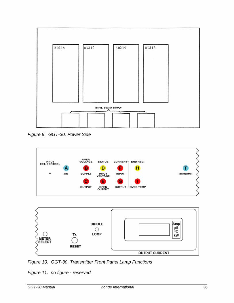
Figure 9. GGT-30, Power Side
Figure 10. GGT-30, Transmitter Front Panel Lamp Functions Figure 11. no figure - reserved

GGT-30 Manual Zonge International 37
Figure 12. Board 93e: Drive Board
Figure 13. Board 131a: Phase Control and Protection

GGT-30 Manual Zonge International 38
Figure 14. SCR Driver Waveform 38.4 KHz Burst
Figure 15. SCR Drive Waveform Sequence

GGT-30 Manual Zonge International 39
Figure 16. Voltage across SCR and Gate Drive, 400V, 8.0A Time: 0.5 ms/div; Scale: Top 20 V/div, Bottom 1 V/div Ground hooked to A-phase on range switch Top Trace: H.V. Probe on negative side of control bridge Bottom Trace: Gate lead of SCR2 on Module A Output: 400 V, 8 A
Figure 17. Voltage across SCR and Gate Drive Same as Figure 16 Output: 150V, 2.7A
GGT-30 Manual Zonge International 40
Figure 18. Normal Gate Drive Pulse for Semikron Top: Input voltage across pulse transformer 5 V/div, 10 us/div
Figure 19. Gate Current across 10 ohm resistor Scale: 2 V/div, 0.5 ms

GGT-30 Manual Zonge International 41
Figure 20. Gate Drive Top: Expanded view, 0.1 ms/div Bottom: Gate voltage under load, 0.5 ms/div Scale: 2 V/div
GGT-30 Manual Zonge International 42
Figure 21. Power Cable, Military Plug, Transmitter end
Figure 22. Power Cable Phase Diagrams

GGT-30 Manual Zonge International 43
Figure 23. GGT-30, SCR Wiring Diagram - Heatsink
Figure 24. GGT-30, IGBT Wiring Diagram - Heatsink

GGT-30 Manual Zonge International 44
Figure 25. GGT-30, Major Boards and Components
Figure 26. GGT-30, Chassis Wiring – (pre IGBT)

Technical Support: (888) 41-ASTEC or (407) 241-2752Americas: (760) 930-4600 Europe (UK) 44 (1384) 842-211 Asia (HK) 852-2437-9662
102
Special Features
Electrical Specs
110 WattsLPQ110 Series
InputInput range 85-264 VAC
120-300 VDC Frequency 47-440 HzInrush current <18 A peak @ 115 VAC;
<36 A peak @ 230 VAC, cold start @ 25°C
Input current 2.5 A max. (RMS) @ 115 VACEfficiency 70% typical at full loadEMI filter FCC Class B conducted
CISPR 22 Class B conductedEN55022 Class B conductedVDE 0878 PT3 Class B conducted
Safety groundleakage current <0.5 mA @ 50/60 Hz, 264 VAC input
OutputMaximum power 80 W for convection;
110 W with 30 CFM forced airAdjustment range ±5% min. on main; 5-25 V on 4th
output on LPQ112 and LPQ113Cross regulation ±2% on output 1; ±3% on outputs
2, 3 & 4Hold-up time 20 ms @ 80 W load, 115 VAC
nominal lineOverload protection Short circuit protection on all
outputs. Case overload protected @110-145% above peak rating
Overvoltage protection 5.7-6.7 VDC on main output.Latching type, recycle AC to reset.
Logic ControlPower Failure TTL logic signal goes high 50-150
msec after 5 V output. It goes low atleast 4 msec before loss of regulation.
Remote sense Compensates for 0.5 V lead dropmin. Will operate without remotesense connected. Reverseconnection protected.
Operating temperature: 0° to 50°C ambientderate each output at 2.5% per degree from 50°to 70°C
Electromagnetic susceptibility: Designed tomeet IEC 801, -2, -3, -4, -5, -6, Level 3
Humidity: Operating; non-condensing 5% to 95%
Vibration: Three orthogonal axes, sweep at 1 oct/min, 5 min. dwell at four major resonances0.75 G peak 5 Hz to 500 Hz, operational
Storage temperature: -40° to 85°C
Temperature coefficient: ±.04% per °C
MTBF demonstrated: >550,000 hours at full loadand 25°C ambient conditions
• Universal input • High efficiency• Remote sense on main output• Built-in EMI filter• Low output ripple• Adjustable 5 V output• Overvoltage protection• Overload protection• Adjustable floating 4th output
(On LPQ112 and LPQ113)• Power fail• Optional L bracket (-B suffix)• Cover kit available LPX110-C
Environmental
VDE 0805/EN60950 (IEC950) 11774-3336-1245 (LC #84997)UL UL1950 E132002CSA CSA 22.2-234 Level 3 LR53982CNEMKO EN 60950/EMKO-TUE P94102464
(74-sec) 203CB Certificate and report 1423, 1424, 1425CE Mark (LVD)
Electrical Specs
Total Power: 80-110 WattsInput Voltage: 85-264 VAC
120-300 VDC# of Outputs: Quad
rev 12.10.03

EUROPE
Astec House, Waterfront Business ParkMerry Hill, Dudley
West Midlands, DY5 1LX, UKTelephone: 44 (1384) 842-211Facsimile: 44 (1384) 843-355
AMERICAS
5810 Van Allen WayCarlsbad, CA 92008
Telephone: 760-930-4600Facsimile: 760-930-0698
103
www.astecpower.com
Ordering Information
ASIA
Units 2111-2116, Level 21Tower1, Metroplaza
223, Hing Fong RoadFwai Fong, New Territories
Hong KongTelephone: 852-2437-9662Facsimile: 852-2402-4426
Model Output Minimum Maximum Load with Maximum Load with Peak Regulation2 RippleNumber Voltage Load Convection Cooling 30 CFM Forced Air Load1 P/P (PARD)3
LPQ112 5 V 2 A 9 A 11 A 15 A ±2% 50 mV12 V 0 A 4.5 A 5 A 9 A ±3% 120 mV-12 V 0 A 0.7 A 1.0 A 1.5 A ±5% 120 mV±5-25 V 0 A 2.5 A 3 A 3.5 A ±3% 240 mV, max.
LPQ113 5 V 2 A 9 A 11 A 15 A ±2% 50 mV15 V 0 A 4.5 A 5 A 9 A ±3% 150 mV-15 V 0 A 0.7 A 1.0 A 1.5 A ±5% 150 mV±5-25 V 0 A 2.5 A 3 A 3.5 A ±3% 240 mV, max.
LPQ114 5 V 2A 9 A 11 A 15 A ±2% 50 mV12 V 0 A 4.5 A 5 A 9 A ±3% 120 mV-12 V 0 A 0.7 A 1.0 A 1.5 A ±5% 120 mV24 V 0.5 A 3.5 A 4.5 A 5 A +10 / -5% 240 mV
1. Peak current lasting <30 seconds with a maximum 10% duty cycle.2. At 25°C including initial tolerance, line voltage, load currents and output voltages adjusted to factory settings.3. Peak-to-peak with 20 MHz bandwidth and 10 µF in parallel with a 0.1 µF capacitor at rated line voltage and load ranges.4. 4th O/P adjustable 5 to 25 V, factory set at 5 V.5. Minimum loads are required.Note: -B suffix added to model number indicates L bracket option.
4.0"�(101.6)
3.5"�(88.9)
0.25"�(6.35)
0.25"�(6.35)
6.5"�(165.1) 7.0"�
(177.8)
1.80"�(45.7)
0.12"�(3)
SK 1
SK 2
1�2�3�4�5�6�7�8�9�
10�11�12
0.156" (4)DIA (4 places)
1
3 NL
GND
4th O/P ADJ
SK 202�(POK)�
1 2SK 201�(+S) 1�(-S) 2
5V O
/P AD
J
M1
M2
Connector LPQ112 LPQ113 LPQ114
SK1-1 GND GND GNDSK1-3 Neutral Neutral NeutralSK1-5 Line Line Line
SK2-1 +5 V +5 V +5 VSK2-2 +5 V +5 V +5 VSK2-3 +5 V +5 V +5 VSK2-4 Common Common CommonSK2-5 Common Common CommonSK2-6 Common Common CommonSK2-7 Common Common CommonSK2-8 +12 V +15 V +12 VSK2-9 +12 V +15 V +12 VSK2-10 -12 V -15 V -12 VSK2-11 +5-25 V +5-25 V +24 VSK2-12 -5-25 V -5-25 V CommonSK201-1 +sense +sense +senseSK201-2 -sense -sense -senseSK202-1 POK POK POKSK202-2 GND GND GND
Mating ConnectorsAC Input: Molex 09-50-8051 (USA)
09-91-0500 (UK)PINS: 08-58-0111
DC Outputs: Molex 09-50-8121 (USA)09-91-1200 (UK)PINS: 08-58-0111
Remote sense/Power fail:Molex 22-01-1022 (USA)22-01-1023 (UK)PINS: 08-50-0114
Astec Connector Kit #70-841-008, includes all of the above.
Notes:1. Specifications subject to change without notice.2. All dimensions in inches (mm), tolerance is ± 0.02”3. Specifications are for convection rating at factory settings unless otherwise stated.4. Mounting holes M1 and M2 should be grounded for EMI purposes.5. Mounting hole M1 is safety ground connection.6. L bracket mounting (6-32) maximum insertion depth is .20” (5).7. Warranty: 1 year8. Weight: 1.25 lb./0.57 kg
Pin Assignments
LPQ110 Series
4.28"�(108.6)
2.5"�(63.5)
6.4"�(162.6) 7.3"�
(185.5)
2.2"�(56)
��
5.9"�(150.0)
0.86"�(21.8)
#6-32 PEM�6 places
-B Bracket