Optical encoder - WEDS/WEDL series MotionUSA - Your Source ...
®
OHLA® Overhung
Load Adaptors
Increase Motor Durability And Life
CD-ROM Sizing
SoftwareCD-ROM Sizing
Software

ZERO-MAX Is AWorld-Leading Expert InOverhung Load TechnologyThe first complete line of SAE “A” through SAE“F” mount OHLA overhung load adaptors wasdesigned by ZERO-MAX. We set the industrystandard with the OHLA design. Today, weprovide immediate shipment of standard modelsfrom stock.
From the smallest Model 200 SAE “A” mount tothe largest Model 1500 SAE “F” mount, OHLA'sfeature rugged housings of cast iron, shafts of130,000 PSI stress-proof steel, ball or tapered-roller bearings, many different shaft options andattractively painted housings. All models may beeither face or foot-mounted.
We offer many custom options or we'll create aspecial design for your application when needed.
TimberProcessing
Construction
Call a ZERO-MAX technical sales representative now. There's a model and size OHLA tohandle every design need–or we'll engineer a special one just for you. 1-800-533-1731
Count On OHLA's For These Important Benefits:• Eliminates premature motor or pump failure
due to overhung loads (axial and radial) onyour motor or pump shaft.
• Prevents contamination of hydraulic fluid inharsh environments.
• Provides a solid, permanent mounting surface.• Permits the removal of hydraulic motors for
servicing without disturbing driven gears,pulleys or sprockets.
• Seals out dirt and grime.
2
OHLA®O V E R H U N G L O A D A D A P T O R S

Recycling
Forestry
3
OHLA
®INDEX
Model 200 SAE “A” MountApplications utilizing SAE “A” 2-bolt mount with ball bearings for motor or pump shafts up to 1 inch in diameter (see page 4).
Model 300 SAE “A” MountSAE “A” 2-bolt mount with same mounting dimensions as Model 200, but utilizes larger ball bearings which allow for heavier overhung loads and a larger input bore diameter (up to 1.25") (see page 5).
Model 400 4-bolt mounting (non-SAE) accommodates same loads as the Model 200 with ball bearings for motor and pump shafts up to 1 inch in diameter (see page 6).
Model 500 SAE “A” MountSAE “A” 4-bolt mount, which uses tapered-roller bearings. Standard input bores include: 1-1/4" keyed, 1"-6B spline, or 14 tooth 12/24 spline (see page 7).
Model 600 SAE “B” MountSAE “B” 2- or 4-bolt mount using tapered-roller bearings. Standard input bores include: 7/8", 1", or 1-1/4" keyed; 13 tooth 16/32 spline, or 15 tooth 16/32 spline. Also available with 1" keyed through-bore as a standard (see page 8).
Model 800 SAE “C” Mount SAE “C” 2- or 4-bolt mount using tapered-roller bearings. Standard input bores include: 7/8",1", or 1-1/4" keyed; 14 tooth 12/24 spline. Also available with 1" keyed through-bore as a standard (see page 9).
Model 900 SAE “C-C” MountSAE “C” 2- or 4-bolt mount with same mounting dimensions as the Model 800, but using larger tapered-roller bearings which allow for heavier overhung loads and a larger input bore diameter. Standard input bores include: 1-1/2", or 1-3/4" keyed; 14 tooth 12/24 spline, or 17 tooth 12/24 spline (see page 10).
Model 1100 SAE “D” Mount SAE “D” mount using large tapered-roller bearings for heavy-duty applications. Standard input bores include: 1-3/4" keyed, or 13 tooth 8/16 spline (see page 11).
Model 1250 SAE “E” Mount & Model 1500 SAE “F” Mount Both the SAE “E” and SAE “F” mounts have the same physical size; only the pilot diameter and bolt circle are different for motor or pump mounting. These models use large spherical-roller bearings for heavy-duty applications. Input bores are made to customer specifications up to a 2-1/2" diameter (see page 12).
Custom ModelsModified dimensions and special features are available (see page 13).

Ø .531 THRU (2)
2
OR 1/2-13 X .75 DP.4.187
1
2.125
1.156
2.312
Ø
5.25 AS CAST
4.12
S
GREASEFITTING
S
AS CAST
±
4.40
"
4
S TA N D A R D M O D E L S
OHLA® 200
Model* Output Shaft - Keyway Input Bore - Keyway
210 1.00 - 1/4 x 1/8 1.00 - 1/4 x 1/8210F 1.00 Bore - 1/4 x 1/8 1.00 - 1/4 x 1/8215 1.50 - 3/8 x 3/16 1.00 - 1/4 x 1/8
210-10 1.00 - 1/4 x 1/8 .625 - 5/32 x 5/64210-12 1.00 - 1/4 x 1/8 .750 - 3/16 x 3/32215-12 1.50 - 3/8 x 3/16 .750 - 3/16 x 3/32
*0.125 Pilot depth is Standard. Add "DP" to Model Number for a Deep Pilot. (0.25) Example: 210-DP
• For SAE “A” 2-bolt mount applications with motor or pump shafts up to 1" diameter.
• Features deep-grooved ball bearings.
• Accepts speeds up to 4400 RPM with proper lubrication. See Page 15.
O V E R H U N G L O A D A D A P T O R S
1.25
.44 1.750
3/8-16 UNC X .75 DP (4)
2
Ø 3.251+.002-.000
+.000-.002
PILOT BORE
INPUTBORE
OUTPUT SHAFT
"A"2.87
.120
FULL DEPTH
5
SEAL
HOUSING
BEARING
G
SPACER RING
PILOTØ 3.250
2.00
F
1.44
A
±.005
4
"B"
STANDARDHOUSINGDEEP PILOTHOUSING
"A"2.875
3.000
.125
.250
+.005-.000
-.000+.005
"B"
3/8-16 UNC X .75 DP (4)
2.75
5.75
Ø 3.251
1.38
INPUTBORE
Ø 3.250
2.00
1.38
RETAINING RING(SEE NOTE).44
+.005-.000 DEEP
.120±.005
NOTE: FOR .250 DEEP PILOTRETAINING RING IS REMOVED
3.000
1.750
+.002-.000+.000
-.002 PILOT BORE
.125
OUTPUT SHAFT
FULL DEPTH
SEAL
HOUSING
BEARING
PILOT
F
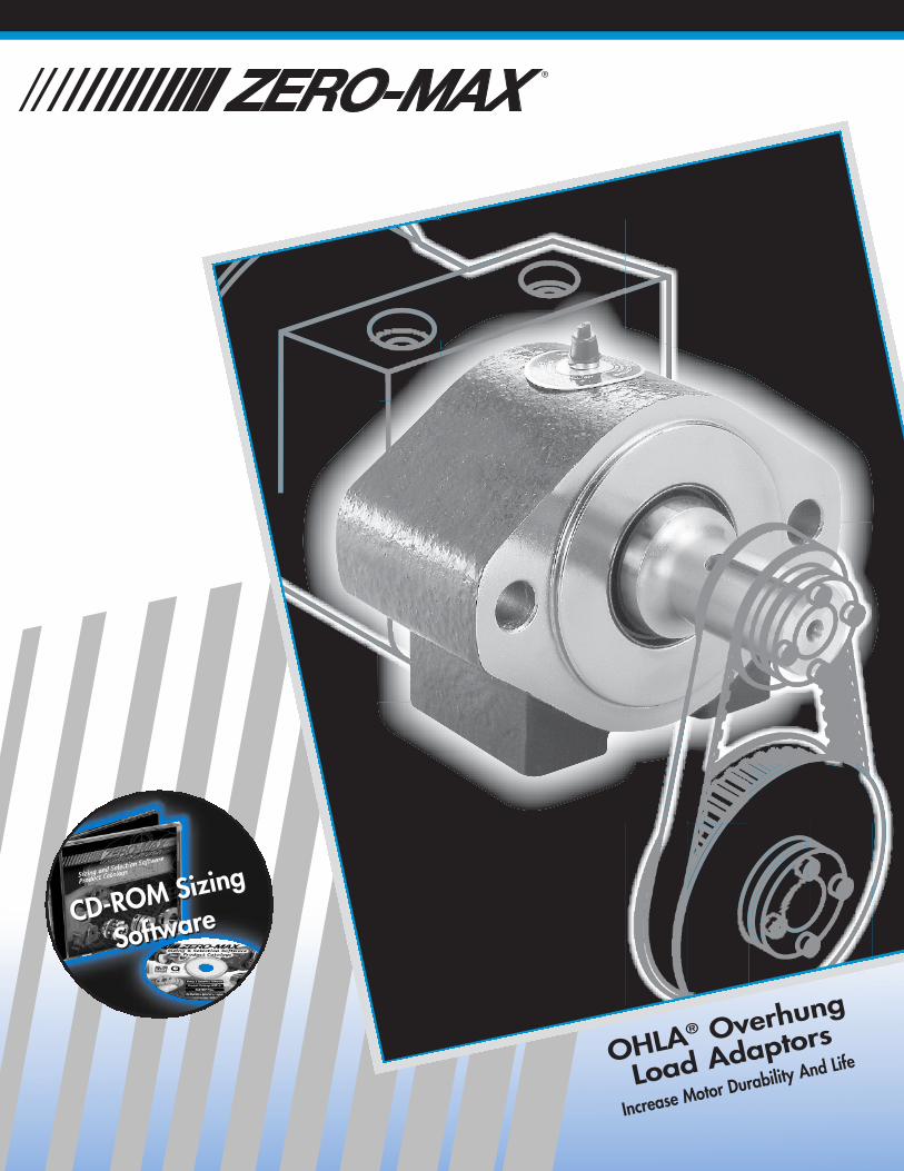
OHLA® 300
• For SAE “A” 2-bolt mount for mediumto heavy-duty applications.
• Features deep-grooved ball bearings.
• Featuring the same overall size as the Model 200, the Model 300 has larger bearings for heavy-dutyapplications.
• Accepts speeds up to 3550 RPM withproper lubrication. See Page 15.
O V E R H U N G L O A D A D A P T O R S
5
S TA N D A R D M O D E L SModel* Output Shaft - Keyway Input Bore - Keyway
312 1.25 - 5/16 x 5/32 1.25 - 5/16 x 5/32315 1.50 - 3/8 x 3/16 1.25 - 5/16 x 5/32300F 1.25 Bore - 5/16 x 5/32 1.25 - 5/16 x 5/32
*0.125 Pilot depth is Standard. Add "DP" to Model Number for a Deep Pilot. (0.25) Example: 312-DP
Ø .531 THRU (2)
4.187
1.156
2.312
2.125
5
5.25 AS CAST
4.12AS CAST
4.40
GREASEFITTING

1.25
.44
2.8752.75
.120
Ø 2.500
1.38
1.755 +.005-.000
2.00
5.63
.125+.000-.005 DEEP
1.750
3/8-16 UNC X .75 (4)
+.000-.005 PILOT BOREINPUT
BORE
OUTPUT SHAFT
FULL DEPTH
SEAL
HOUSING
BEARING
PILOT RING
PILOT
F
±.005
2.125
.
2.312
3.62 AS CAST
4.21
3.93AS CAST
1.156
Ø.406 THRU (4) 90° APART ON A Ø3.250 BOLT CIRCLEGREASE FITTING
6
S TA N D A R D M O D E L S
OHLA® 400
Model Output Shaft - Keyway Input Bore - Keyway
410 1.00 - 1/4 x 1/8 1.00 - 1/4 x 1/8410F 1.00 Bore - 1/4 x 1/8 1.00 - 1/4 x 1/8415 1.50 - 3/8 x 3/16 1.00 - 1/4 x 1/8
• For applications with motor or pumpshafts up to 1" diameter.
• Features deep-grooved ball bearings.
• Accepts speeds up to 4400 RPM withproper lubrication. See Page 15.
O V E R H U N G L O A D A D A P T O R S

3/8-16 UNC X 1.00 DP. (4)
2
.875 2.500
2.254.250
1
2.250
Ø 3.253 +.005-.000
PILOT BORE.250 +.005
-.000
INPUTBORE
PILOT RINGWAVE SPRING
REAR SEAL
BEARING
FRONTSEAL
FULL DEPTH
OUTPUT SHAFT
±.005
1.87
F
1.125
+.000-.002
PILOTØ 3.250
1 6.50
5
.125
OHLA® 500
• For SAE “A” heavy-duty bearing blockapplications with 4-bolt mounting.
• Features heavy-duty tapered rollerbearings.
• May be used on 2-bolt mount by tilting22-1/2°.
• Accepts speeds up to 3300 RPM withproper lubrication. See Page 15.
O V E R H U N G L O A D A D A P T O R S
7
S TA N D A R D M O D E L SModel Output Shaft - Keyway Input Bore - Keyway
512-20 1.250 - 5/16 x 5/32 1.250 - 5/16 x 5/32512-6BS 1.250 - 5/16 x 5/32 1.000 6B Spline512-14S 1.250 - 5/16 x 5/32 14 Tooth 12/24 Spline515-20 1.500 - 3/8 x 3/16 1.250 - 5/16 x 5/32
515-6BS 1.500 - 3/8 x 3/16 1.000 6B Spline515-14S 1.500 - 3/8 x 3/16 14 Tooth 12/24 Spline
22.5
45
.1.6253.250
2.562
2
1/2-13 X 1-1/4 DP MTG. HOLES (4)ON A Ø4.187 BOLT CIRCLE EACH END
4.94AS CAST
1/4-18 NPT (4)(GREASE FITTING OR VENT)
6
4.50 AS CAST
5.60
5.25 AS CAST
.
7/16-14 X .75 DEEP (4)
.73
+.004-.000
PILOT BORE
+.005-.000
±.005
OUTPUT SHAFT
FULL DEPTH
FRONT SEALHOUSING
BEARING
REAR SEAL
RETAINING RING
PILOTØ4.000+.000
-.003
F
1.00
(
2.007.00
2.65
5.00
.500.500
1.69
3.0001.250
Ø 4.001INPUTBORE
.594 DIA. THRU (4)LOCATED ON A 5.000 DIA. BOLT CIRCLE
.594 DIA. THRU (2)(GREASE FITTING
OR VENT)
AS CAST5.12
5.78
7.00 AS CAST
3.4361.718
2.750
5.7501/4-18 NPT
8
S TA N D A R D M O D E L S
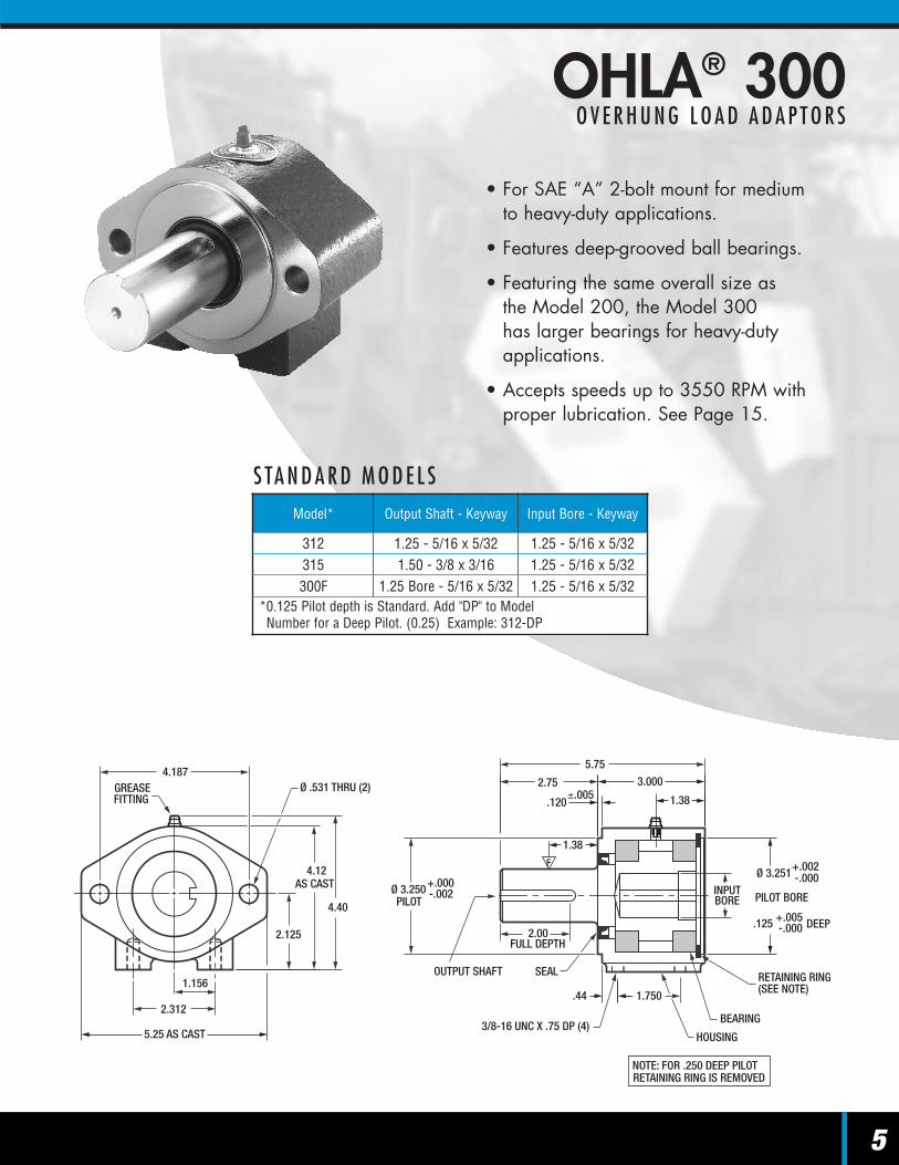
OHLA® 600
Model Output Shaft - Keyway Input Bore - Keyway
615-13S 1.500 - 3/8 x 3/16 13 Tooth 16/32 Spline615-15S 1.500 - 3/8 x 3/16 15 Tooth 16/32 Spline615-14 1.500 - 3/8 x 3/16 .875 - 1/4 x 1/8*615-16 1.500 - 3/8 x 3/16 1.000 - 1/4 x 1/8**615-20 1.500 - 3/8 x 3/16 1.250 - 5/16 x 5/32600F-16 1.00 Bore - 1/4 x 1/8 1.00 - 1/4 x 1/8
*3/16 Keyway Optional **5/16 Keyway Optional
• For SAE “B” mount motor or pumpapplications.
• Features heavy-duty tapered rollerbearings.
• Accepts speeds up to 3300 RPM withproper lubrication. See Page 15.
O V E R H U N G L O A D A D A P T O R S

.495 .500
.
1/2-13 X 1.00 DEEP (4)
4.000.750
Ø5.000
3.00 6.00
3.12
Ø5.001INPUTBORE
+.004-.000
PILOT BORE
+.005-.000
RETAINING RING
HOUSING
BEARING
REAR SEAL
±.005
+.000-.003
OUTPUT SHAFT
FULL DEPTH
FRONT SEAL
2.69
PILOT
F
1.50
9.00
6 .83
OHLA® 800
• For SAE “C” mount motor or pumpapplications.
• Features heavy-duty tapered rollerbearings.
• Accepts speeds up to 3300 RPM withproper lubrication. See Page 15.
O V E R H U N G L O A D A D A P T O R S
9
S TA N D A R D M O D E L SModel Output Shaft - Keyway Input Bore - Keyway
815-14S 1.500 - 3/8 x 3/16 14 Tooth 12/24 Spline815-14 1.500 - 3/8 x 3/16 .875 - 1/4 x 1/8*815-16 1.500 - 3/8 x 3/16 1.000 - 1/4 x 1/8**815-20 1.500 - 3/8 x 3/16 1.250 - 5/16 x 5/16800F-16 1.00 Bore - 1/4 x 1/8 1.00 - 1/4 x 1/8
*3/16 Keyway Optional**5/16 Keyway Optional
.593 DIA. THRU (4)LOCATED ON A 6.375 DIA. BOLT CIRCLE
(2) .687 DIA. THRU
1
3.375
2.125
4.250
7.125
(GREASE FITTING OR VENT)
8
6.38AS CAST
7.04
8.50 AS CAST
1/4-18 NPT

3.12.
1/2-13 X 1.00 DEEP (4)
.750 4.000
6.00 3.00
.495
.500
Ø5.000
2
INPUTBORE
Ø 5.001+.004-.000
PILOT BORE
+.005-.000
REAR SEAL
HOUSING
RETAINING RING
BEARING
FRONT SEAL
FULL DEPTH
PILOT
±.005
OUTPUT SHAFT
+.000-.003
2.75
F
1.50
9.00
.687 DIA. THRU (2)
.594 DIA THRU (4)LOCATED ON A 6.375 DIA. BOLT CIRCLE
2.125
4.250
3.375
7.125
(GREASE FITTINGOR VENT)
6.38AS CAST
7.04
8.50 AS CAST
1/4-18 NPT
10
S TA N D A R D M O D E L S
OHLA® 900
Model Output Shaft - Keyway Input Bore - Keyway
915-14S 1.500 - 3/8 x 3/16 14 Tooth 12/24 Spline915-17S 1.500 - 3/8 x 3/16 17 Tooth 12/24 Spline915-24 1.500 - 3/8 x 3/16 1.500 - 3/8 x 3/16915-28 1.500 - 3/8 x 3/16 1.750 - 7/16 x 7/32
928-14S 1.750 - 7/16 x 7/32 14 Tooth 12/24 Spline928-17S 1.750 - 7/16 x 7/32 17 Tooth 12/24 Spline928-24 1.750 - 7/16 x 7/32 1.500 - 3/8 x 3/16928-28 1.750 - 7/16 x 7/32 1.750 - 7/16 x 7/32
• For SAE “C-C” mount motor or pumpapplications.
• Features heavy-duty tapered rollerbearings.
• Accepts speeds up to 2700 RPM withproper lubrication. See Page 15.
O V E R H U N G L O A D A D A P T O R S

OHLA® 1100
• For SAE “D” mount motor or pumpapplications.
• Features heavy-duty, tapered rollerbearings.
• Accepts speeds up to 3500 RPM withproper lubrication. See Page 15.
O V E R H U N G L O A D A D A P T O R S
11
S TA N D A R D M O D E L SModel Output Shaft - Keyway Input Bore - Keyway
1136-28 2.250 - 1/2 x 1/4 1.750 - 7/16 x 7/321136-13S 2.250 - 1/2 x 1/4 13 Tooth 8/16 Spline
1.38
5.00
TAPEREDBEARING
RETAINING RING
INPUTBORE
+.005-.000
PILOT BORE
Ø 6.000
.515.500
4.00FULL DEPTH
OUTPUT SHAFT
+.000-.005
PILOTØ6.000
9.50
14.50
6.250
REAR SEAL
LOCKNUT WASHER
FRONT SEAL
88.500
10.25 AS CAST
9.00 DIA. BOLT CIRCLE
3/4-10 X 1.5 DP.(6) EACH SIDE ON A
5.000
9.00AS CAST
1
GREASE FITTINGS (2)1/4-18 NPT
3/4 - 16 THREAD(2) #8 O-RING BOSS
(4) 3/4-10 UNCX 1.50 DEEP

3.56
1.0-8 X 2.00 DEEP (4)
1
7.002/7.008 DIA.FOR SAE F MOUNT
6.503/6.507 DIA.FOR SAE E MOUNT
INPUT BORE
7.000/6.995 DIA.FOR SAE F MOUNT
6.500/6.495 DIA.FOR SAE E MOUNT
F
7.131.06 5.000
OUTPUT SHAFT
FULL DEPTH
.625
4.13
.500
5.00
SEAL
BEARING
6
13.25
1.13
7.500
3
1.0-8 X 2.00 DEEP 90 APART(4) ON A 13.781 DIA. B.C. INPUT END ONLY
7FOR SAE F MOUNTING
FOR SAE E MOUNTING
3/4-10 X 2.00 DEEP 90° APART(4) ON A 12.500 B.C. INPUT END ONLY
.42 DIA. THRU1/2-13 X 1.25 DP.FOR I-BOLT (3) PLACES
13.00 AS CAST
5.50011.000 7
6.00 AS CAST
1
12
S TA N D A R D M O D E L S
OHLA® 1250 & 1500
Model Output Shaft - Keyway Input Bore - Keyway
1250 SAE E Customer Specified Customer Specified1500 SAE F Customer Specified Customer Specified
• For SAE “E” or “F” mount motor or pumpapplications with up to 2-1/2" diameterinput bore. Spline input bores available.
• Available in up to 3-1/2 inch diameteroutput shaft. Special input and outputsavailable.
• Features heavy-duty, spherical rollerbearings.
• Accepts speeds up to 2300 RPM withproper lubrication. See Page 15.
O V E R H U N G L O A D A D A P T O R S

OHLA® SPECIALSO V E R H U N G L O A D A D A P T O R S
13
There’s a model and sizeOverhung Load Adaptor foryour need...or we’ll designone for you. In the U.S. callTOLL FREE 1-800-533-1731.
• Special Input Bores
• Special Splines
• Output Diameter Changes
• Splined Output Shafts
• Threaded Output Shafts
• Tapered Output Shafts
• Extended Output Shafts
• O-ring Bosses
• Drilled And Tapped End Shafts
• Grease Fittings Or Vents
• Face Mounting Tapped Holes
• Magnetic Speed SensorModifications
• Special Shaft material And Heat Treating
• High Pressure Seals
• Housing Modifications
• Special SAE Input Versus Output Mounting
... and many more!

1. Determine proper SAE flange mount foryour application (SAE A, B, C, C-C, D, E, F)
2. Calculate the overhung load using thefollowing formula:
OHL (Overhung Load) = 63000 x HP x FN x R
HP = Transmitted HorsepowerN = RPM of ShaftR = Radius of sprocket, pulley, etc. in inchesF = Load Connection Factor
3. Calculate bearing life of the selected modelusing the formulas from the following table:
Note:
The bearing life calculations shown are tobe used for radial loading only.Consult factory if more complex loading(Radial, Axial, Tangential) is present.
Lubrication: (See page 15)
Specials
Your application may require a modifiedshaft or housing to fit an existingapplication or to simplify a new design. See "Options" (p 13).
Load Connection Factor1.00 - Single Chain Drives
1.25 - Spur or Helical Gear Drives or Double Chain Drives
1.50 - V-Belt Drives2.00 - Timing Belt Drives2.50 - Flat Belt Drives
14
OHLA® SIZING AND SELECTINGO V E R H U N G L O A D A D A P T O R S
Overhung LoadAdaptor
Overhung Load
V E R T I C A L A P P L I C AT I O N SFor applications where the shaft isvertical – consult factory for special
bearing and lubrication requirements
Model S Calculated Life
200 S = .603 X +1.406
300 S = .606 X +1.485
400 S = .603 X +1.485
500 S = .704 X +1.930
600 S = .714 X +2.086
800 S = .448 X +1.704
900 S = .442 X +1.761
1100 S = .179 X +1.285
1250, 1500 S = .219 X +1.384
4,960S • OHL
L10 = )3(16,667RPM
3,762S • OHL
L10 = )3.331,500,000RPM (
L10 = )3(16,667RPM
3,762S • OHL
L10 = )3(16,667RPM
4,906S • OHL
4,960S • OHLL10 = )3.331,500,000
RPM (4,960
S • OHLL10 = )3.331,500,000RPM (
7,610S • OHLL10 = )3.331,500,000
RPM (12,000S • OHLL10 = )3.331,500,000
RPM (71,500S • OHLL10 = )3.331,500,000
RPM (X – Distance from front end of the OHLA housing to the applied radial load.

Visit the Zero-Max website for additional technical information
at www.zero-max.com
Sizing software for Overhung Load Adaptors.Zero-Max provides free software on a CDROM to help select and size the correctOverhung Load Adaptor. This CD ROMcontains all Zero-Max product catalogs in aPDF format, a comprehensive sizing andselection program and CAD drawingsfor most of the Zero-Max products.
The sizing and selection portion of thesoftware walks the user through theselection of any Zero-Max product andgives a recommendation on whichmodel to use.
The software is very user friendly and can be usedon any Windows or Macintosh based computer. 15
*Per Grease Fitting
200 Series
300 Series
400 Series
500 Series
600 Series
800 Series
900 Series
1100 Series
1250 Series
1500 Series
= Use Grease = Consult Factory for Lubrication Requirements
1500 2300
1500 2300
35002500
1900 2700
2300 3300
2300 3300
2300 3300
3800 4400
3100 3550
3800 4400
RPM 1500 25001000500 2000 3000 3500 4000
HH O R I Z O N TA L A P P L I C AT I O N S
G R E A S E C A PA C I T YMinimum Maximum
200 Series .5 oz. 1.0 oz.300 Series .7 oz. 1.4 oz.400 Series .4 oz. 1.0 oz.500 Series 2.0 oz. 4.0 oz.600 Series 2.2 oz. 4.4 oz.800 Series 2.8 oz. 5.6 oz.900 Series 4.3 oz. 8.6 oz.
1100 Series* 14.0 oz. 14.0 oz.1250 Series 11.0 oz. 22.0 oz.1500 Series 11.0 oz. 22.0 oz.
G R E A S E T Y P E V E R T I C A L A P P L I C AT I O N SIndoor Conditions NLGI #1 or NLGI #2
Outdoor ConditionsNLGI #1 or NLGI #2
(Synthetic GreaseRecommended)
Severe Conditions Consult Factory
For applications where the shaft isvertical – consult factory for special
bearing and lubrication requirements
LUBRICATION
Additional Zero-Max® Motion Control Products
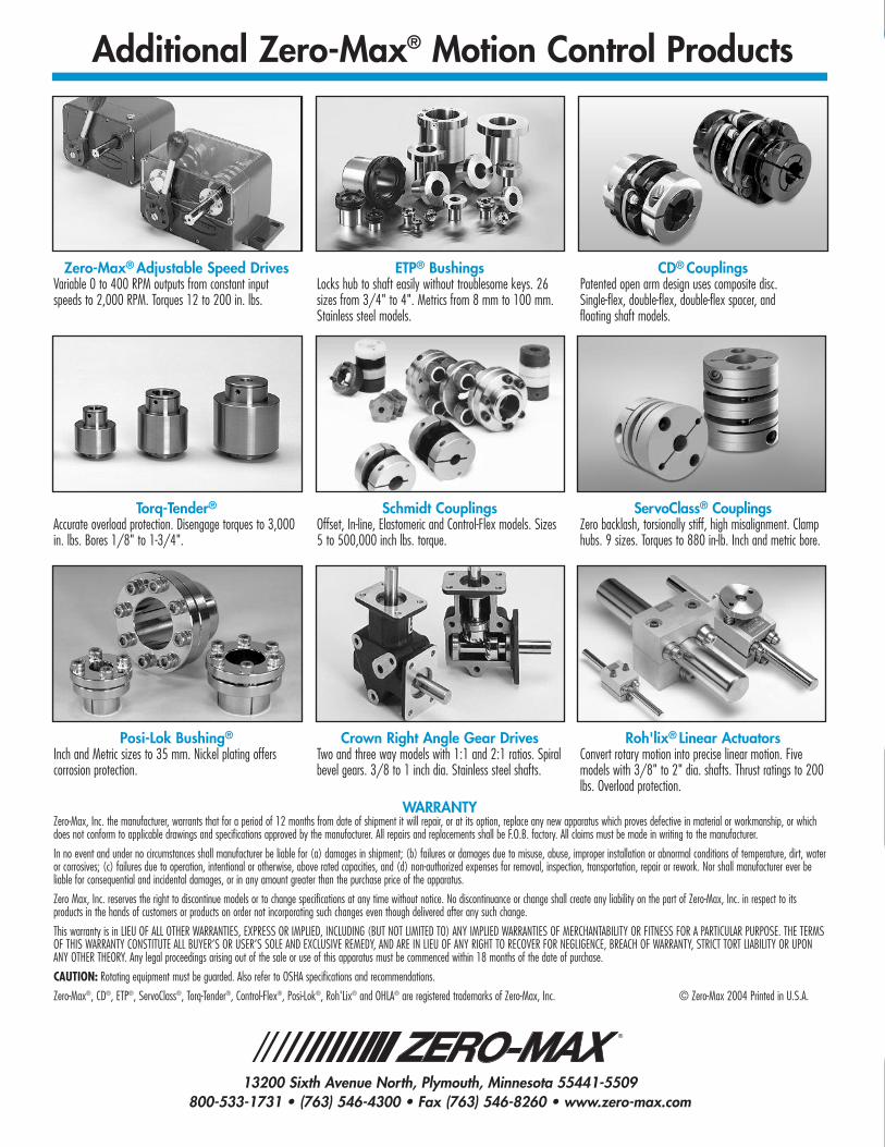
Torq-Tender®
Accurate overload protection. Disengage torques to 3,000in. lbs. Bores 1/8" to 1-3/4".
Schmidt CouplingsOffset, In-line, Elastomeric and Control-Flex models. Sizes5 to 500,000 inch lbs. torque.
ServoClass® CouplingsZero backlash, torsionally stiff, high misalignment. Clamphubs. 9 sizes. Torques to 880 in-lb. Inch and metric bore.
Posi-Lok Bushing®
Inch and Metric sizes to 35 mm. Nickel plating offerscorrosion protection.
Crown Right Angle Gear DrivesTwo and three way models with 1:1 and 2:1 ratios. Spiralbevel gears. 3/8 to 1 inch dia. Stainless steel shafts.
Roh'lix® Linear ActuatorsConvert rotary motion into precise linear motion. Fivemodels with 3/8" to 2" dia. shafts. Thrust ratings to 200lbs. Overload protection.
Zero-Max® Adjustable Speed DrivesVariable 0 to 400 RPM outputs from constant inputspeeds to 2,000 RPM. Torques 12 to 200 in. lbs.
ETP® BushingsLocks hub to shaft easily without troublesome keys. 26sizes from 3/4" to 4". Metrics from 8 mm to 100 mm.Stainless steel models.
CD® CouplingsPatented open arm design uses composite disc. Single-flex, double-flex, double-flex spacer, and floating shaft models.
WARRANTYZero-Max, Inc. the manufacturer, warrants that for a period of 12 months from date of shipment it will repair, or at its option, replace any new apparatus which proves defective in material or workmanship, or whichdoes not conform to applicable drawings and specifications approved by the manufacturer. All repairs and replacements shall be F.O.B. factory. All claims must be made in writing to the manufacturer.
In no event and under no circumstances shall manufacturer be liable for (a) damages in shipment; (b) failures or damages due to misuse, abuse, improper installation or abnormal conditions of temperature, dirt, wateror corrosives; (c) failures due to operation, intentional or otherwise, above rated capacities, and (d) non-authorized expenses for removal, inspection, transportation, repair or rework. Nor shall manufacturer ever beliable for consequential and incidental damages, or in any amount greater than the purchase price of the apparatus.
Zero Max, Inc. reserves the right to discontinue models or to change specifications at any time without notice. No discontinuance or change shall create any liability on the part of Zero-Max, Inc. in respect to itsproducts in the hands of customers or products on order not incorporating such changes even though delivered after any such change.
This warranty is in LIEU OF ALL OTHER WARRANTIES, EXPRESS OR IMPLIED, INCLUDING (BUT NOT LIMITED TO) ANY IMPLIED WARRANTIES OF MERCHANTABILITY OR FITNESS FOR A PARTICULAR PURPOSE. THE TERMSOF THIS WARRANTY CONSTITUTE ALL BUYER’S OR USER’S SOLE AND EXCLUSIVE REMEDY, AND ARE IN LIEU OF ANY RIGHT TO RECOVER FOR NEGLIGENCE, BREACH OF WARRANTY, STRICT TORT LIABILITY OR UPONANY OTHER THEORY. Any legal proceedings arising out of the sale or use of this apparatus must be commenced within 18 months of the date of purchase.
CAUTION: Rotating equipment must be guarded. Also refer to OSHA specifications and recommendations.
Zero-Max®, CD®, ETP®, ServoClass®, Torq-Tender®, Control-Flex®, Posi-Lok®, Roh'Lix® and OHLA® are registered trademarks of Zero-Max, Inc. © Zero-Max 2004 Printed in U.S.A.
13200 Sixth Avenue North, Plymouth, Minnesota 55441-5509800-533-1731 • (763) 546-4300 • Fax (763) 546-8260 • www.zero-max.com
®