
your reliable partner - mayr€¦ · your reliable partner EAS ... EAS®-HT short bearing-supported...
28
www. .com www. .com Reliable High Torque safety clutches for heavy load applications K.4050.V00.EN your reliable partner EAS ® -HT
Transcript of your reliable partner - mayr€¦ · your reliable partner EAS ... EAS®-HT short bearing-supported...

www. .comwww. .com
Reliable High Torquesafety clutches for heavy load applications
K.4050.V00.EN
your reliable partner
EAS®-HT

your reliable partner2
Always in use
EAS®-HT safety clutches for heavy load applica-tions prolong the availability of your production systems.
They increase your profit, prevent damage caused by overload and save costs.
EAS®-HT safety clutchesthe reliable, non-destructive overload protection
● Disengaging ● Steplessly adjustable ● Precise ● Compact ● Robust
www.mayr.com2

your reliable partner 3
Tested safety
For more than 40 years, we have been dimensioning, developing and manufacturing safety clutches for heavy load applications.
You can rely on the tested reliability and safety of our heavy load clutch.
Experts, not experiments as safety does not allow for compromises
safe – reliable – innovative 3

your reliable partner
4
EAS®-HT short bearing-supported hub Torque:4 to 40 kNm
Sizes 7 to 10
Type 4050._0400
• Direct attachment of the drive element on the bearing-supported, output-side clutch flange.
• The bearing is able to absorb high additional forces in axial and radial directions.
Page 6
EAS®-HT lastic Torque:4 to 40 kNm
Sizes 7 to 10
Type 4053._0400
• Double shaft design with a flexible, positive locking coupling
• Absorbs impact-type loads
Page 8
EAS®-HT flange design Torque:7.5 to 440 kNm
Sizes 0 to 6
Type 4060.71400
• Compact, ready-to-install module • Can easily be integrated into the drive line
Page 10
EAS®-HT Toothed coupling Torque:7.5 to 440 kNm
Sizes 0 to 6
Type 4061.71400
• Double shaft design• Toothed coupling with crowned teeth cutting• Robust and temperature-resistant• High misalignment compensation capability
Page 12
EAS®-HT backlash-free Torque:7.5 to 140 kNm
Sizes 0 to 4
Type 4062.71400
• Double shaft design with a torsionally rigid, backlash-free disk pack coupling
• High torsional rigidity• Backlash-free torque transmission• Maintenance-free
Page 14
EAS®-HT lastic bolt Torque:40 to 260 kNm
Sizes 3 to 5
Type 4063.70400
• Double shaft design with a flexible, positive locking coupling
• Absorbs impact-type loads
Page 16
4

your reliable partner
5
EAS®-HT Options
Customer-specific designsLow temperature designAlternative shaft connectionsATEX Page 18
EAS®-elements• Standard• Reinforced
• Torque limiting or force limiting elements • Installation into two flanges located towards one
another • Integration into existing constructions possible
Page 20
Technical ExplanationsGeneralPre-selectionMisalignment compensation capability
Page 23
High-speed clutches EAS®-HSE
Torque:100 to 8.400 Nm
Sizes 02 to 0
Type 404_ . _04_ _
Reliable overload protection at high speeds
For more information as well as detailed Technical Data and Dimensions, please see our product catalogue EAS®-HSC/ EAS®-HSE.
Extruder clutches EAS®-dutytorque
Torque:70 to 17.000 Nm
Sizes 2 to 9
Type 4043. _1400
Protect extruder screws from expensive damage caused by overload
For more information as well as detailed Technical Data and Dimensions, please see our product catalogue EAS®-dutytorque.
Rustproof design Corrosion-protected safety clutches for env-ironmental and waste water technology
Additional branch-optimised EAS® safety clutches
5

L
b1
I
Ød 0
s
b2 b
z
Øe
Øm
Øf 1
ØF
ØM
Øf 2
Øf 3
Ød
b3
b4
your reliable partner
6
EAS®-HT
Short bearing-supported hub Type 4050._0400Sizes 7 to 10
Order Number
__ / 4 0 5 0 . __ 0 4 0 0 / __ / __ / __
Sizes 7 to 10
Torque range 1)
lowmediumhighvery high
4567
Bores 1)
Ø dH7
Bore Ø d0
Torque adjust-ment value
[kNm]
Keyway acc. DIN 6885/1 - P9
Example: Order Number 8 / 4050.60400 / 90 / 35 / 84050.60400 / 90 / 35 / 81) Position of the keyway to the tapped hole “s” in the thrust piece is not defined. Defined position available on request.
Stroke
6

your reliable partner
7
EAS®-element clutch
We reserve the right to make dimensional and constructional altera-tions.
Max. permitted forces on the flange con-nection
Sizes
7 8 9 10
Radial forcesType 4050._0400
FR [kN] 15 20 30 40
Axial forces FA [kN] 10 15 20 30
Technical DataSizes
7 8 9 10
Limit torques for overload
Type 4050.40400 MG [kNm] 1.3 - 2.6 1.6 - 3.2 4 - 8 5 - 10
Number of EAS®-elements 2 2 2 2
Type 4050.50400 MG [kNm] 2 - 4 3.2 - 6.4 6 - 12 10 - 20
Number of EAS®-elements 3 4 3 4
Type 4050.60400 MG [kNm] 2.6 - 5.2 4.8 - 9.6 8 - 16 15 - 30
Number of EAS®-elements 4 6 4 6
Type 4050.70400 MG [kNm] 4 - 8 6.5 - 13 12 - 24 20 - 40
Number of EAS®-elements 6 8 6 8Sizes EAS®-elements 0 0 1 1Maximum speed nmax [rpm] 3000 2800 2500 2200
Bolt stroke on overload [mm] 6 6 8 8
Mass moments of inertia and weightsSizes
7 8 9 10EAS®-hub-side Type 4050._0400 J [kgm²] 0.18 0.38 1.05 2.37
Flange side Type 4050._0400 J [kgm²] 0.17 0.38 1.3 2.65
Weight at dmax Type 4050._0400 [kg] 47 76 145 232
Bores [mm]Sizes
7 8 9 10EAS®-hub-side dmax 90H7 110H7 135H7 160H7
Flange side d0 max 30 40 48 58
Dimensions[mm]
Sizes
7 8 9 10
b 25 30 35 35
b1 66 78 94 110
b2 12.5 12.5 15 15
b3 44 44 56 56
b4 70.5 100.5 119.3 159.3
eh7 147 165 242 276
F 260 304 380 450
f1 237.5 279.5 359.5 417.5
f2 120 165 190 245
f3 110 155 180 230
L 228 270 330 387
I 140 170 210 250
M 180 225 270 340
m 190 220 285 325
s 8xM16 8xM20 8xM24 12xM24
z 4 4 5 6
7

Øf 4
Øf 5
Ød 1
L1
Ød
Ød 0
Øf 2
ØM
ØF
l1 l
b1b3 b5 b6
b2
b4
a
Øf 3
Øf 4
Øf 5
Ød 1
L1
Ød
Ød 0
Øf 2
ØM
ØF
l1l
b1b3 b5 b6
b2
b4
a
Øf 3
your reliable partner
8
lastic Type 4053._0400Sizes 7 to 10
Stroke
EAS®-HT
Order Number
__ / 4 0 5 3 . __ 0 4 0 0 / __ / __ / __ / __
Sizes 7to10
Torque rangelowmediumhighvery high
4567
BoreØ dH7
Bore Ø d0
Bore Ø d1
H7
Torque adjust-ment value
[kNm]
Keyway acc. DIN 6885/1 - P9
Example: Order Number 8 / 4053.60400 / 90 / 35 /115 / 8
8

your reliable partner
9
We reserve the right to make dimensional and constructional alterations.Dimensions[mm]
Sizes
7 8 9 10
a 5.5 8 8 8
b1 66 78 94 110
b2 12.5 12.5 15 15
b3 44 44 56 56
b4 70.5 100.5 119.3 159.3
b5 76 86.5 102 108
b6 76 86.5 102 108
F 260 304 380 450
f2 120 165 190 245
f3 110 155 180 230
f4 164 208 275 289
f5 265 330 415 480
L1 469.5 548.5 668 754
I 137 156 196 220
I1 140 170 210 250
M 180 225 270 340
Mass moments of inertia and weightsSizes
7 8 9 10
Mass moments of inertia
EAS®-hub-side J [kgm²] 0.18 0.38 1.05 2.37
Flexible side J [kgm²] 0.57 1.62 5.0 10.7
Weight at dmax [kg] 85 154 282 464
Bores [mm]Sizes
7 8 9 10EAS®-hub-side dmax 90H7 110H7 135H7 160H7
Bearing flange d0 max 30 40 48 58
Flexible side d1 max 115H7 135H7 180H7 200H7
EAS®-element clutch
1) The values refer to 1500 rpm.
Technical DataSizes
7 8 9 10
Limit torques for overload
Type 4053.40400 MG [kNm] 1.3 - 2.6 1.6 - 3.2 4 - 8 5 - 10
Number of EAS®-elements 2 2 2 2
Type 4053.50400 MG [kNm] 2 - 4 3.2 - 6.4 6 - 12 10 - 20
Number of EAS®-elements 3 4 3 4
Type 4053.60400 MG [kNm] 2.6 - 5.2 4.8 - 9.6 8 - 16 15 - 30
Number of EAS®-elements 4 6 4 6
Type 4053.70400 MG [kNm] 4 - 8 6.5 - 13 12 - 24 20 - 40
Number of EAS®-elements 6 8 6 8Sizes EAS®-elements 0 0 1 1Maximum speed nmax [rpm] 2250 2000 1500 1400
Bolt stroke on overload [mm] 6 6 8 8
Flexible shaft coupling
Permitted misalign-ments 1)
axial ∆Ka [mm] ±2.5 ±2.5 ±2.5 ±2.5
radial ∆Kr [mm] 0.3 0.3 0.3 0.3
angular ∆Kw [mm] 0.3 0.3 0.3 0.3
Nominal and maximum torques, flexible coupling
TKN [kNm] 5.8 9.9 20.5 28TK max [kNm] 8.3 14.5 27 66
9

L
ØF
ØD
Øe
Øb
Øi
Øi
Øe
ØD
Øb
f f
your reliable partner
10
EAS®-HT
flange design Type 4060.71400Sizes 0 to 6
Order Number
__ / 4 0 6 0 . 7 1 4 0 0 / __
Sizes 0 to 6 Torque adjust-ment value
[kNm]
Example: Order number 5/ 4060.71400 / 200
10

your reliable partner
11
EAS®-element clutch
We reserve the right to make dimensional and constructional alterations.
Mass moments of inertia and weightsSizes
0 1 2 3 4 5 6EAS®-element-side J [kgm²] 0.25 0.5 1.16 2.71 5.51 16.29 27.87
EAS®-pressure flange side J [kgm²] 0.19 0.37 0.96 2.05 4.22 10.29 19.3
Weight at dmax [kg] 56 77 142 212 303 627 814
Dimensions[mm]
Sizes
0 1 2 3 4 5 6
bh7 175 230 255 310 340 460 540
e 214 269 306 360 400 531 618
D 234 292 330 390 430 567 660
F 275 320 380 455 545 640 740
f 3 3 4 4 5 6 6
i 11 13 13 17 17 21 25
L 226 243 298 312 328 476 485
Technical DataSizes
0 1 2 3 4 5 6
Limit torques for overload
MG [kNm] 7.5 - 15 12.5 - 25 20 - 40 37.5 - 75 70 - 140125 - 250
220 - 440
Number of EAS®-elements 6 8 6 8 12 10 10
Sizes EAS®-elements 0 0 1 1 1 2 2 1)
Maximum speed nmax [rpm] 2000 1750 1500 1250 1000 900 750
Bolt stroke on overload [mm] 6 6 8 8 8 12 12
11
Ød 2
Ød 3
ØD
2
Øf 1
Øf
ØF
ØD
1
Ød 1
Ød
L3
l1 l
L L2
L1
your reliable partner
12
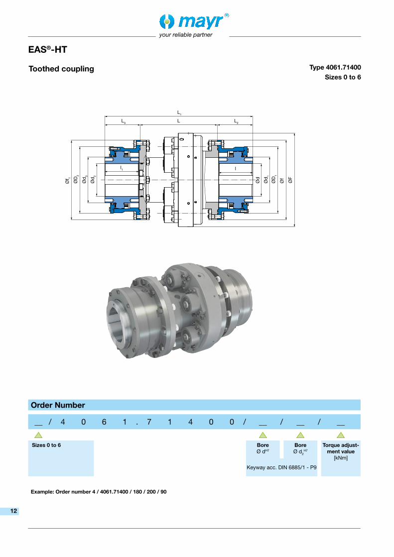
Toothed coupling Type 4061.71400Sizes 0 to 6
EAS®-HT
Order Number
__ / 4 0 6 1 . 7 1 4 0 0 / __ / __ / __
Sizes 0 to 6 BoreØ dH7
Bore Ø d2
H7
Torque adjust-ment value
[kNm]
Keyway acc. DIN 6885/1 - P9
Example: Order number 4 / 4061.71400 / 180 / 200 / 90
12

your reliable partner
13
We reserve the right to make dimensional and constructional alterations.Dimensions
[mm]Sizes
0 1 2 3 4 5 6
d1 135 185 210 255 290 400 480
d3 135 185 210 255 290 400 480
D1 195 251 288 337 375 502 584
D2 195 251 288 337 375 502 584
F 275 320 380 455 545 640 740
f 234 292 330 390 430 567 660
f1 234 292 330 390 430 567 660
L 226 242.5 298 312 328 476 485
L1 434 502.5 588 685 740 1012 1125
L2 104 130 145 186.5 206 268 320
L3 104 130 145 186.5 206 268 320
l 100 125 140 180 200 260 310
l1 100 125 140 180 200 260 310
Mass moments of inertia and weightsSizes
0 1 2 3 4 5 6EAS®-pressure flange side J [kgm²] 0.27 0.65 1.48 3.33 6.43 19.17 39.74
EAS®-element side J [kgm²] 0.34 0.78 1.69 3.99 7.72 25.18 48.3
Weight at dmax / d2max [kg] 83 132 220 345 488 1053 1523
Bores [mm]Sizes
0 1 2 3 4 5 6EAS®-pressure flange side dmax 95 130 150 185 210 285 340
EAS®-element side d2 max 95 130 150 185 210 285 340
EAS®-element clutch
1) The values refer to 1500 rpm.2) Per joint
Technical DataSizes
0 1 2 3 4 5 6
Limit torques for overload MG [kNm] 7.5 - 15 12.5 - 25 20 - 40 37.5 - 75 70 - 140125 - 250
220 - 440
Number of EAS®-elements 6 8 6 8 12 10 10
Sizes EAS®-elements 0 0 1 1 1 2 2 1)
Maximum speed nmax [rpm] 2000 1750 1500 1250 1000 900 750
Bolt stroke on overload [mm] 6 6 8 8 8 12 12
Toothed cou-pling
Permitted misalign-ments 1) 2)
axial ∆Ka [mm] ±2 ±3 ±3 ±3 ±3 ±4 ±4
radial ∆Kr [mm] 7.5 8.6 10.2 11.7 12.4 18.4 20.6
angular ∆Kw [mm] 1.25 1.25 1.25 1.25 1.25 1.25 1.25
Nominal and maximum torques, curved-tooth coupling
TKN [kNm] 12.5 25 40 63 100 250 400TK max [kNm] 25 50 80 12.6 200 500 800
13
L3 L L2L4
L1
Ød 2
Ød 3
ØD
1
ØF
ØD
Ød 1
Ød
l
your reliable partner
14
L3 L L2L4
L1
Ød 2
Ød 3
ØD
1
ØF
ØD
Ød 1
Ød
l
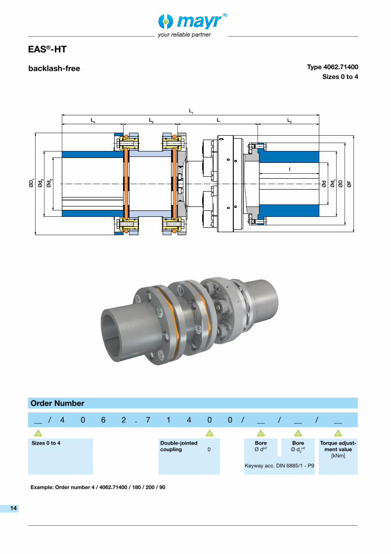
backlash-free Type 4062.71400Sizes 0 to 4
EAS®-HT
Order Number
__ / 4 0 6 2 . 7 1 4 0 0 / __ / __ / __
Sizes 0 to 4 Double-jointed coupling 0
BoreØ dH7
Bore Ø d2
H7
Torque adjust-ment value
[kNm]
Keyway acc. DIN 6885/1 - P9
Example: Order number 4 / 4062.71400 / 180 / 200 / 90
14

your reliable partner
15
We reserve the right to make dimensional and constructional alterations.Dimensions[mm]
Sizes
0 1 2 3 4
d1 186 230 243 300 321
d3 186 215 243 279 321
D 234 292 330 390 430
D1 290 332 378 431 492
F 275 320 380 455 545
L 229 245.5 302 316 330
L1 735 811.5 934 1054.5 1173
L2 175 200 225 265 310
L3 155.6 166 182 208.4 223
L4 175 200 225 265 310
l 171 195 219 260 302
Mass moments of inertia and weightsSizes
0 1 2 3 4
Mass moments of inertia
Hub side J [kgm²] 0.35 0.76 1.58 3.68 6.56
torsionally rigid side J [kgm²] 0.86 1.73 3.5 7.1 13.95
Weight at dmax [kg] 132 195 308 468 665
Bores [mm]Sizes
0 1 2 3 4Hub-side dmax 140 170 180 220 240
Torsionally rigid side d2 max 140 160 180 210 240
EAS®-element clutch
1) The values refer to 1500 rpm.
Technical DataSizes
0 1 2 3 4
Limit torques for overload MG [kNm] 7.5 - 15 12.5 - 25 20 - 40 37.5 - 75 70 - 140
Number of EAS®-elements 6 8 6 8 12
Sizes EAS®-elements 0 0 1 1 1
Maximum speed nmax [rpm] 2000 1750 1500 1250 1000
Bolt stroke on overload [mm] 6 6 8 8 8
Torsionally rigid shaft coupling
Permitted misalign-ments 1)
axial ∆Ka [mm] 1.6 1.7 2.1 2.3 2.3
radial ∆Kr [mm] 1.0 1.0 1.1 1.3 1.4
angular ∆Kw [°] 0.4 0.4 0.4 0.4 0.4
Nominal and maximum torques, torsionally rigid all-steel coupling
TKN [kNm] 22 33 50 73 110TK max [kNm] 44 66 100 146 220
15

l
L2L2 L
L1
Ød 2
Ød 3
ØD
1
ØF
ØD
Ød 1
Ød
your reliable partner
16
lastic bolt Type 4063.70400Sizes 4 to 6
EAS®-HT
Order Number
__ / 4 0 6 3 . 7 0 4 0 0 / __ / __ / __
Sizes 4 to 6 BoreØ dH7
Bore Ø d2
H7
Torque adjust-ment value
[kNm]Keyway acc. DIN 6885/1 - P9
Example: Order number 4 / 4063.70400 / 270 / 180 / 90
16

your reliable partner
17
We reserve the right to make dimensional and constructional alterations.Dimensions[mm]
Sizes
4 5 6
d1 321 420 500
d3 320 360 450
D 430 567 660
D1 660 760 920
F 545 640 740
L 375 533 543
L1 946 1201 1231
L2 310 350 370
L3 250 300 300
l 302 342 362
Mass moments of inertia and weightsSizes
4 5 6
Mass moments of inertia
Hub side J [kgm²] 6.6 20.02 39.63
Flexible side J [kgm²] 22.35 55.18 110.68
Weight at dmax [kg] 706 1407 1956
Bores [mm]Size
4 5 6
Hub-side dmax 240 300 340
Flexible side d2 max 225 250 320
EAS®-element clutch
1) The values refer to 1500 rpm.
Technical DataSizes
4 5 6
Limit torques for overload MG [kNm] 40 - 80 72.5 - 145 130 - 260
Number of EAS®-elements 12 10 10
Sizes EAS®-elements 1 2 2
Maximum speed nmax [rpm] 1000 900 750
Bolt stroke on overload [mm] 8 12 12
Flexible shaft coupling
Permitted misalign-ments 1)
axial ∆Ka [mm] ±4 ±4 ±4
radial ∆Kr [mm] 1.5 1.5 1.5
angular ∆Kw [mm] 4.6 5.3 6.4
Nominal and maximum torques, flexible coupling
TKN [kNm] 48 100 160TK max [kNm] 96 200 320
17

your reliable partner
18
EAS®-HT with automatic re-engagement
After overload occurrence, the EAS®-HT safety clutch is disengaged. It is possible to engage the EAS®-HT safety clutch via remote control by means of automatic re-engagement. Re-engagement can be carried out pneumatically, hydraulically, electromechanically or mechanically.
EAS®-HT with mechanical disengagement Mechanical disengagement device for the EAS®- elements.The EAS®-elements can be disengaged individually mechanically.
EAS®-HT with engagement bowl Engagement without aids.Automatic engagement device for low operating speeds. Direct overload query possible through switching disk.
EAS®-HT radial EAS®-HT radial for small construction space length values and low to medium operating speed values.
EAS®-HT Options
For the EAS®-HT clutches, designs specially created according to customer requests and different variants are also available.EAS®-HT clutches can be combined with additional attachment parts.
We are happy to advise you on the dimensioning and configuration of your optimum design.
18

your reliable partner
19
EAS®-HT with integrated drive elements
EAS®-HT, integrated attachment of sprocket and toothed wheels, V-belt disks etc.
EAS®-HT for roller gears Highest torques at lowest diameters. The alternative to hydraulic clamping sets and shear pins in rolling mills.
Frictionally-locking shaft-hub connection Frictionally-locking shaft-hub connections:
● Shrink disk (see Fig.)
● External shrink disk
● Oil press fit
EAS®-HT low temperature design Reliable overload protection in case of very low temperatures to -48 °C.
(Please contact the manufacturer separately for this).
ATEX design EAS®-HT safety clutches are also available in ATEX design according to the directive 94/9 EC (ATEX 95).(Please contact the manufacturer separately for this).
EAS®-HT Options
19

your reliable partner
20
Application � EAS®-elements for installation in two bea-ring-supported flanges facing each other or for integration into existing constructions
� As EAS®-HT safety clutch component
� For customer-specific constructions
Applications � Conveyor belts
� Crushers
� Rolling mills
� Underground mining / mining
� Raw material extraction
Advantages/Benefits � Safe overload protection
� Can be used flexibly and in modular form
� Maximum performance density
� Release forces adjustable
� Easy and quick engagement
� Large number of disengagement procedures
EAS®-element
Rustproof design available on request
your reliable partner
Function:Positive locking transmission of circumferential force and axial force.In case of overload, the EAS®-elements separate the input and output mechanically, so that the system can slow down freely. Manual re-engagement of the individual elements (automatic re-engagement available on request).
The catalogue contains basic information on pre-selection and dimensioning.
For detailed information on selecti-on, dimensioning, installation, initial operation and maintenance, please see the Installation and Operational Instructions.
20

Øt
Øn
SW
Øn
e Ød 0
ØA
1
s ØA
y1 l1 y2
a1
vl
L1
Øt
L
l
Øn
Øt
30°
60° (6x)
30°
ØM
ØA0
SW
Øm
ØA1
s s
ØA
2
ØA
2
Ød 0
Ød 1 S ØA
y1 l1 y2a1
v
L
l2s1
l
L2
L1
b
l
Øn
Øt
30°
60° (6x)
30°
ØM
ØA0
SW
Øm
ØA1
s s
ØA
2
ØA
2
Ød 0
Ød 1 S ØA
y1 l1 y2a1
l v
L
l2s1
l
L2
L1
b
your reliable partner
21
EAS®-element
Standard Type 440._04.0Sizes 02 to 01Stroke
Type 440._04.0Sizes 0 to 2Stroke
Reinforced Type 441.604.0Sizes 0 to 2
Stroke
21

your reliable partner
22
EAS®-element
We reserve the right to make dimensional and constructional alterations.
Dimensions[mm]
Sizes
02 01 0 1 2
A H8h7 28 38 55 75 100
A0 - - 85 110 150
A1 28 35 55 75 100
A2 - - 55 75 108
a1 1.0 1.5 2 2 3
b - - 12 15 20
d0 10 14 20 30 40.6
d1H8h7 - - 30 40 60
e 31.2 41.6 - - -
L 28 40 73 96 160
L1 15 21 52 65 80
L2 - - 42 51 70
I 12 15 30 40 50
Technical DataSizes
02 01 0 1 2
Circumferential force
Type 440.404.0(Low torque range)
Fu min [kN] 0.22 1 1.8 5 4Fu max [kN] 0.54 2 5 10 11
Type 440.504.0(Medium torque range)
Fu min [kN] 0.5 1.25 3.75 7.5 10Fu max [kN] 1.4 2.5 7.5 15 30
Type 440.604.0(High torque range)
Fu min [kN] 1.2 2.5 7.5 15 30Fu max [kN] 2.5 5 15 30 60
Type 441.604.0Reinforced design
Fu min [kN] - - 19 38 75Fu max [kN] - - 38 75 150
Axial force
Type 440.404.0(Low torque range)
Fax min [kN] 0.2 0.9 1.62 4.5 3.6Fax max [kN] 0.48 1.8 4.5 9 9.9
Type 440.504.0(Medium torque range)
Fax min [kN] 0.45 1.12 3.37 6.75 9Fax max [kN] 1.26 2.25 6.75 13.5 27
Type 440.604.0(High torque range)
Fax min [kN] 1.08 2.25 6.75 13.5 27Fax max [kN] 2.25 4.5 13.5 27 54
Type 441.604.0Reinforced design
Fax min [kN] - - 10 20 40Fax max [kN] - - 20 40 80
Bolt stroke on overload [mm] 2.5 4 6 8 12
Weights [kg] 0.25 0.6 1.75 4.1 11.3
1) Tightening torque MA = 40 Nm2) Tightening torque MA = 60 Nm3) Fixing screw DIN EN ISO 4762 10.9 MA = 9 Nm
4) Fixing screw DIN EN ISO 4762 10.9 MA = 19 Nm5) Fixing screw DIN EN ISO 4762 10.9 MMA = 76 Nm6) y1 and y2 are extension dimensions
Dimensions[mm]
Sizes
02 01 0 1 2
I1 7 10 22 30 40
I2 - - 12 17 22
M - - 72 95 128
m - - 44 60 80
n 17 22 31 48 69
S - - M12 M20 M24
s M24x1 1) M30x1,5 2) M6 3) M8 4) M12 5)
s1 - - M5 M6 M8
SW 27 36 19 30 36
t 3 4 5 6 8
v 2 3 3 4 15
y1 6) 12 15 8 10 10
y2 6) 16 21 38 50 65
Order Number
__ / 4 4 0 . __ 0 4 . 0
Size02 01012
Torque range lowmediumhigh
456
Example: Order number 0 / 440.504.0
Order Number
__ / 4 4 1 . 6 0 4 . 0
Size012
Example: Order number 0 / 441.604.0
EAS®-element Standard EAS®-element Reinforced
22

your reliable partner
23
Technical explanations EAS®-HT safety clutch
Operating principle of the EAS®-HT safety clutchOverload elements
❒ If the proportional circumferential force on the individual elements proves too large, the resulting axial force causes an axial movement of the bolt via the ball/calotte system and therefore the disconnection of the torque transmission.
❒ The maximum circumferential force is individually determined through the adjusting nut and mayr®-cup springs. The transmittable torque is determined in this way.
❒ Due to the axial stroke of the bolt (ball carrier), the control segments move radially outwards, thereby disconnecting the components axially.
❒ Re-engagement of the balls through a bolt stroke in the direction of the calotte takes place either manually or via a mayr® re-engagement device (pneumatic, hydraulic, electromechanical or mechanical).
Rustproof design available on request
Engaged
Disengaged
Characteristics � Positive locking torque transmission acc. to the ball-detent principle
� Adjustable torque
� Separates disengagingly
� Easy repeat operation start-up
� Robust
� Long service lifetime
Clutch types 4050, 4060 are also suitable for oil-running.
The limit torque for overload on the clutch can be adjusted by changing the cup spring pre-tension of each overload element.
The EAS®-HT safety clutches can be set to the required limit torque for overload at the place of manufacture. Subsequent torque changes can be carried out using the Adjustment Diagram included in the delivery (see respective Installation and Operational Instructions).
Design
All clutch parts are made of steel. EAS®-HT safety clutch basic components have a zinc-phosphated surface which provides a basic corrosion protection for further surface treatments.
23

3.24
2
3.3 3.4 3.5 3.6 3.7 3.1
1
F F
your reliable partner
24
Fig. 3
Technical explanations EAS®-HT safety clutch
Re-engagement:
Turn the hub part 1 and the output flange 2 into the correct angular position to one another (re-engagement position can be recognized via the marking bores on the clutch outer diameter, Fig. 3). By ap-plying axial pressure on the bolt end, bolts 3.1 are brought back to their engaged position. The clutch is ready for operation when all clutch overload elements are engaged.
Maintenance
The EAS®-HT safety clutches do not require special maintenance work. They are largely protected against dust and humidity, they have an initial grease filling and are therefore mainly maintenance-free.
EAS®-elements Please find a detailed description in the respective Installation and Operational Instructions (go to www.mayr.com). Special maintenance work may be necessary, however, if the device is subject to large amounts of dirt or dust or is operating in extreme ambient conditions.
In this case, please contact the manufacturer.
Fig. 2: EAS®-element clutch disengaged
Processes for torque switch-off on overload:
On overload, the hub part 1 and the output flange 2 begin to turn against each other. The bolts 3.1 in the overload elements are pressed via the control segments 3.4 against the force of the cup springs 3.6 from the thrust washers 3.2. The control segments 3.4 travel radially outwards over the bolt 3.1 switching edge and hold the bolts 3.1 in a disengaged position (see Fig. 2). The positive locking connection of the hub part 1 and the output flange 2 is nullified. The originally coupled masses can slow down freely. The drive is switched off electrically via speed monitoring device 4.
Markings forre-engagement
Markings for re-engagement
Markings for re-engagement
Tool e.g. lever Plastic hammer
Mounting onto the shaft:
In a standard delivery, the EAS®-HT safety clutches are delivered with a finish bore and a keyway acc. DIN 6885/1 P9. The clutch can be secured axially onto the shaft e.g. using a washer and a screw, screwed into the shaft threaded centre hole.
Optionally, we deliver a frictionally-locking shaft-hub connection (see EAS®-HT options, page 19).
24

your reliable partner
25
Pre-selection of the clutch
Technical explanations EAS®-HT safety clutch
TN =9550 × P
[Nm]n
TG ≈ TN × KB [Nm]
Particularly in case of load-side vibration generation (e.g. piston compressors / shredding machines / etc.) or alternating torques please contact us to select a reliable, tried and tested overload protection for your production systems.
Here, the overload clutch is combined with suitable clutches, depending on the application: � Elastomer coupling � Shaft Couplings � Curved-tooth coupling
Profit from our many years of market and application experience in different branches.
Drive lines in heavy engineering are robust and designed for operation in adverse conditions. In contrast to systems with servomo-tor-driven drives, the torque course and the system behaviour often cannot be determined precisely.
Frequently, only the drive power of the motor and the permitted max. torque of the gear output are known.
Using tried-and-tested operating factors, clutch sizes suitable for the application can be pre-selected.
Names:
TN [Nm] Nominal torque of the motor
TG [Nm] Pre-selected release torque on the overload clutch
P [KW] Input power motor
n [rpm] Speed
KB [-] Service factor
Service factors:
2.5 - 3medium impacts
Stirring units / pumps (viscid fluids) / kneading machines / mixing systems / conveyor belts / etc.
3 - 5high impacts
Shredding machines / centrifuges / crushers / roll trains / construction machines / mining machines / etc.
In normal operation, the EAS®-HT transmits the set overload torque via positive locking. All torques for normal operation, including torque peaks, must be transmitted safely and must not cause the safety clutch to respond.
Often, the actual complex of loads (impacts) during operation (e.g. for shredding machines / mixers) are not known and can only be measured in the system with great effort. Using software specially developed for the purpose, it is possible to simulate the behaviour in case of collisions of such drive lines. The prerequisite is that all specifications are known:
� Mass moments of inertia � Rigidities of all overload elements, including the overload clutch � Parameters of the motor and the control circuit
Pre-selection
25
∆Ka
∆Kw
∆Kr
∆Ka
∆Kw
∆Kr
your reliable partner
26
47%
100
80
60
40
20
20%
33%
40 60 80 100
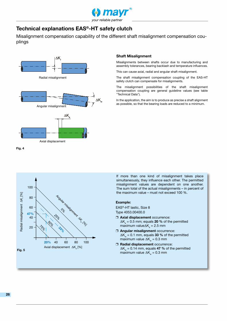
If more than one kind of misalignment takes place simultaneously, they influence each other. The permitted misalignment values are dependent on one another. The sum total of the actual misalignments – in percent of the maximum value – must not exceed 100 %.
Example:
EAS®-HT lastic, Size 8Type 4053.00400.0
❒ Axial displacement occurrence: DKa = 0.5 mm; equals 20 % of the permitted maximum valueDKa = 2.5 mm
❒ Angular misalignment occurrence: DKw = 0.1 mm, equals 33 % of the permitted maximum value DKw = 0.3 mm
❒ Radial displacement occurrence: DKw = 0.14 mm, equals 47 % of the permitted maximum value DKw = 0.3 mm
Fig. 4
Fig. 5
Shaft Misalignment
Misalignments between shafts occur due to manufacturing and assembly tolerances, bearing backlash and temperature influences.
This can cause axial, radial and angular shaft misalignment.
The shaft misalignment compensation coupling of the EAS-HT safety clutch can compensate for misalignments.
The misalignment possibilities of the shaft misalignment compensation coupling are general guideline values (see table "Technical Data").
In the application, the aim is to produce as precise a shaft alignment as possible, so that the bearing loads are reduced to a minimum.
Axial displacement
Radial misalignment
Angular misalignment
Axial displacement DKa [%]
Rad
ial m
isal
ignm
ent D
Kr [
%]
Angular misalignm
ent DKw [%
]
Technical explanations EAS®-HT safety clutchMisalignment compensation capability of the different shaft misalignment compensation cou-plings
26

your reliable partner
27
❑ tendo®-PMPermanent magnet-excited DC motors
Shaft Couplings
Electromagnetic Brakes/Clutches
DC Drives
Product Summary
❑ smartflex®/primeflex®
Perfect precision couplings for servo and stepping motors ❑ ROBA®-ES
Backlash-free and damping for vibration-sensitive drives ❑ ROBA®-DS/ROBA®-D
Backlash-free, torsionally rigid all-steel couplings ❑ ROBA®-DSM
Cost-effective torque-measuring couplings
❑ ROBA-stop® standardMultifunctional all-round safety brakes
❑ ROBA-stop®-M motor brakesRobust, cost-effective motor brakes
❑ ROBA-stop®-SWater-proof, robust monoblock brakes
❑ ROBA-stop®-Z/ROBA-stop®-silenzio®
Doubly safe elevator brakes ❑ ROBA®-diskstop®
Compact, very quiet disk brakes ❑ ROBA®-topstop®
Brake systems for gravity loaded axes ❑ ROBA®-linearstop
Backlash-free brake systems for linear motor axes ❑ ROBA®-guidestop
Backlash-free holding brake for profiled rail guides ❑ ROBATIC®/ROBA®-quick/ROBA®-takt
Electromagnetic clutches and brakes, clutch brake units
❑ EAS®-Compact®/EAS®-NCPositive locking and completely backlash-free torque limiting clutches
❑ EAS®-smartic®
Cost-effective torque limiting clutches, quick installation ❑ EAS®-element clutch/EAS®-elements
Load-disconnecting protection against high torques ❑ EAS®-axial
Exact limitation of tensile and compressive forces ❑ EAS®-Sp/EAS®-Sm/EAS®-Zr
Load-disconnecting torque limiting clutches with switching function ❑ ROBA®-slip hubs
Load-holding, frictionally locked torque limiting clutches ❑ ROBA®-contitorque
Magnetic continuous slip clutches ❑ EAS®-HSC/EAS®-HSE
High-speed safety clutches for high-speed applications
Safety Clutches/Overload Clutches
27

Representatives
More representatives:
Austria, Belgium, Brazil, Canada, Denmark, Finland, Greece, Hongkong, Hungary, Indonesia, Israel, Luxembourg, Malaysia, New Zealand, Norway, Philippines, Romania, Russia, Slovakia, Slovenia, South Africa, Spain, Sweden, Thailand, TurkeyYou can find the complete address for the representative responsible for your area under www.mayr.com in the internet.
Headquarters
Chr. Mayr GmbH + Co. KGEichenstraße 1, D-87665 MauerstettenTel.: +49 83 41/8 04-0, Fax: +49 83 41/80 44 21www.mayr.com, E-Mail: [email protected]
Branch office
Service Germany
Baden-WürttembergEsslinger Straße 770771 Leinfelden-EchterdingenTel.: 07 11/45 96 01 0Fax: 07 11/45 96 01 10
BavariaEichenstraße 187665 MauerstettenTel.: 0 83 41/80 41 04Fax: 0 83 41/80 44 23
ChemnitzBornaer Straße 20509114 ChemnitzTel.: 03 71/4 74 18 96Fax: 03 71/4 74 18 95
FrankenUnterer Markt 991217 HersbruckTel.: 0 91 51/81 48 64Fax: 0 91 51/81 62 45
HagenIm Langenstück 658093 HagenTel.: 0 23 31/78 03 0Fax: 0 23 31/78 03 25
KamenLünener Straße 21159174 KamenTel.: 0 23 07/23 63 85Fax: 0 23 07/24 26 74
NorthSchiefer Brink 832699 ExtertalTel.: 0 57 54/9 20 77Fax: 0 57 54/9 20 78
Great BritainMayr Transmissions Ltd.Valley Road, Business ParkKeighley, BD21 4LZWest YorkshireTel.: 0 15 35/66 39 00Fax: 0 15 35/66 32 [email protected]
FranceMayr France S.A.S.Z.A.L. du MinopoleRue Nungesser et Coli62160 Bully-Les-MinesTel.: 03.21.72.91.91Fax: [email protected]
ItalyMayr Italia S.r.l.Viale Veneto, 335020 Saonara (PD)Tel.: 0498/79 10 20Fax: 0498/79 10 [email protected]
SingaporeMayr Transmission (S) PTE Ltd.No. 8 Boon Lay Way Unit 03-06, TradeHub 21Singapore 609964 Tel.: 00 65/65 60 12 30Fax: 00 65/65 60 10 [email protected]
SwitzerlandMayr Kupplungen AGTobeläckerstraße 118212 Neuhausen am RheinfallTel.: 0 52/6 74 08 70Fax: 0 52/6 74 08 [email protected]
AustraliaRegal Beloit Australia Pty Ltd.19 Corporate Ave03178 Rowville, VictoriaAustraliaTel.: 0 3/92 37 40 00Fax: 0 3/92 37 40 [email protected]
IndiaNational EngineeringCompany (NENCO)J-225, M.I.D.C. Bhosari Pune 411026Tel.: 0 20/27 13 00 29Fax: 0 20/27 13 02 [email protected]
JapanMATSUI Corporation2-4-7 AzabudaiMinato-kuTokyo 106-8641Tel.: 03/35 86-41 41Fax: 03/32 24 24 [email protected]
NetherlandsGroneman BV Amarilstraat 117554 TV Hengelo OVTel.: 074/2 55 11 40Fax: 074/2 55 11 [email protected]
PolandWamex Sp. z o.o. ul. Pozaryskiego, 2804-703 WarszawaTel.: 0 22/6 15 90 80Fax: 0 22/8 15 61 [email protected]
South KoreaMayr Korea Co. Ltd.Room No.1002, 10th floor, Nex Zone, SK TECHNOPARK, 77-1, SungSan-Dong, SungSan-Gu, Changwon, KoreaTel.: 0 55/2 62-40 24Fax: 0 55/2 62-40 [email protected]
TaiwanGerman Tech Auto Co., Ltd.No. 28, Fenggong Zhong Road, Shengang Dist.,Taichung City 429, Taiwan R.O.C.Tel.: 04/25 15 05 66Fax: 04/25 15 24 [email protected]
Czech RepublicBMC BALTAS s. r. o.Hviezdoslavova 29 b62700 BrnoTel.: 05/45 22 60 47Fax: 05/45 22 60 [email protected]
02/0
5/20
16 G
F/B
E/S
C
Rhine-MainHans-Böckler-Straße 664823 Groß-Umstadt Tel.: 0 60 78/7 82 53 37Fax: 0 60 78/9 30 08 00
your reliable partner
ChinaMayr ZhangjiagangPower Transmission Co., Ltd. Fuxin Road No.7, Yangshe Town215637 ZhangjiagangTel.: 05 12/58 91-75 67Fax: 05 12/58 91-75 [email protected]
USAMayr Corporation10 Industrial AvenueMahwahNJ 07430Tel.: 2 01/4 45-72 10Fax: 2 01/4 45-80 [email protected]