YB110/YB230 FIREYE BurnerLogiX -...
64
1 ® DESCRIPTION The Fireye ® BurnerLogix™ System is a microprocessor based burner management control system designed to provide the proper burner sequencing, ignition and flame monitoring protection on auto- matically ignited oil, gas, and combination fuel burners. In conjunction with limit and operating con- trols, it programs the burner/blower motor, ignition and fuel valves to provide for proper and safe burner operation. Through SMART LED’S, the control provides current operating status and lockout information in the event of a safety shutdown. Optional VFD and LCD displays are available that may be either plugged in or mounted remotely to give full language descriptors of current status and diagnostic lockout information. Refer to BurnerLogix PROGRAMMER SELECTION later in this document for the various combinations of programmer and display modules. A complete BurnerLogix system includes the YB110 (YB230) chassis equipped with the type of flame amplifier required for the application, appropriate flame detector, plug-in programmer mod- ule, wiring base and optional alpha-numeric display. Interchangeable programmer modules allow for complete versatility in selection of function, timing and flame failure response times. The optional alpha-numeric display has 2 lines by 16 characters per line. It is available in either vac- uum fluorescent or liquid crystal formats. The advantage of VFD is high brightness and extended temperature range down to –40°F. Both displays contain a fully functional keypad. You can easily scroll through the various menus to view the current operating status, review programmer configura- tion, and lockout history. When mounted remotely, the displays provide NEMA 4x(IP66) protection. An advantage of the BurnerLogix control family is the ability to set many of the operating parame- ters associated with proper and reliable burner operation allowing inventory of various programmer types to be kept to a minimum. The YB110 (YB230) is a chassis/flame amplifier module complete with mounting screws and blank display module. The display module (BLV512 (vfd) or BLL510 (lcd)), if required, must be ordered separately. Interchangeable YP programmer modules allow for complete versatility in selection of control function, timing, and flame scanning means. Functions such as pre-purge time, recycling or non-recycling interlocks, high fire proving interlock, and trial for ignition timing of the pilot and main flame are determined by the programmer module. The BurnerLogix system can be used with ultra-violet, auto-check infrared, flame rod, self-check ultra-violet flame scanners or direct coupled integrated scanners by choosing the proper chassis/flame amplifier module. YB110/YB230 FIREYE ® BurnerLogiX ™ MICROPROCESSOR-BASED INTEGRATED BURNER MANAGEMENT CONTROL BL-1001 SEPTEMBER 23, 2015 APPROVED
Transcript of YB110/YB230 FIREYE BurnerLogiX -...

1
®
DESCRIPTIONThe Fireye® BurnerLogix™ System is a microprocessor based burner management control systemdesigned to provide the proper burner sequencing, ignition and flame monitoring protection on auto-matically ignited oil, gas, and combination fuel burners. In conjunction with limit and operating con-trols, it programs the burner/blower motor, ignition and fuel valves to provide for proper and safeburner operation. Through SMART LED’S, the control provides current operating status and lockoutinformation in the event of a safety shutdown. Optional VFD and LCD displays are available thatmay be either plugged in or mounted remotely to give full language descriptors of current status anddiagnostic lockout information. Refer to BurnerLogix PROGRAMMER SELECTION later in thisdocument for the various combinations of programmer and display modules.
A complete BurnerLogix system includes the YB110 (YB230) chassis equipped with the type offlame amplifier required for the application, appropriate flame detector, plug-in programmer mod-ule, wiring base and optional alpha-numeric display. Interchangeable programmer modules allow forcomplete versatility in selection of function, timing and flame failure response times.
The optional alpha-numeric display has 2 lines by 16 characters per line. It is available in either vac-uum fluorescent or liquid crystal formats. The advantage of VFD is high brightness and extendedtemperature range down to –40°F. Both displays contain a fully functional keypad. You can easilyscroll through the various menus to view the current operating status, review programmer configura-tion, and lockout history. When mounted remotely, the displays provide NEMA 4x(IP66) protection.An advantage of the BurnerLogix control family is the ability to set many of the operating parame-ters associated with proper and reliable burner operation allowing inventory of various programmertypes to be kept to a minimum.
The YB110 (YB230) is a chassis/flame amplifier module complete with mounting screws and blankdisplay module. The display module (BLV512 (vfd) or BLL510 (lcd)), if required, must be orderedseparately. Interchangeable YP programmer modules allow for complete versatility in selection ofcontrol function, timing, and flame scanning means. Functions such as pre-purge time, recycling ornon-recycling interlocks, high fire proving interlock, and trial for ignition timing of the pilot andmain flame are determined by the programmer module. The BurnerLogix system can be used withultra-violet, auto-check infrared, flame rod, self-check ultra-violet flame scanners or direct coupledintegrated scanners by choosing the proper chassis/flame amplifier module.
YB110/YB230 FIREYE®
BurnerLogiX™
MICROPROCESSOR-BASEDINTEGRATED BURNER
MANAGEMENT CONTROL
BL-1001SEPTEMBER 23, 2015
APPROVED
2
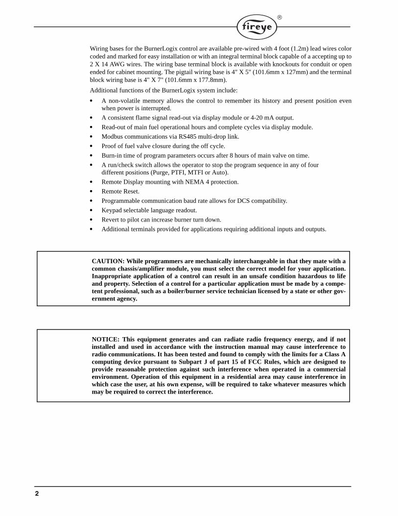
Wiring bases for the BurnerLogix control are available pre-wired with 4 foot (1.2m) lead wires colorcoded and marked for easy installation or with an integral terminal block capable of a accepting up to2 X 14 AWG wires. The wiring base terminal block is available with knockouts for conduit or openended for cabinet mounting. The pigtail wiring base is 4" X 5" (101.6mm x 127mm) and the terminalblock wiring base is 4" X 7" (101.6mm x 177.8mm).
Additional functions of the BurnerLogix system include:
• A non-volatile memory allows the control to remember its history and present position evenwhen power is interrupted.
• A consistent flame signal read-out via display module or 4-20 mA output.
• Read-out of main fuel operational hours and complete cycles via display module.
• Modbus communications via RS485 multi-drop link.
• Proof of fuel valve closure during the off cycle.
• Burn-in time of program parameters occurs after 8 hours of main valve on time.
• A run/check switch allows the operator to stop the program sequence in any of fourdifferent positions (Purge, PTFI, MTFI or Auto).
• Remote Display mounting with NEMA 4 protection.
• Remote Reset.
• Programmable communication baud rate allows for DCS compatibility.
• Keypad selectable language readout.
• Revert to pilot can increase burner turn down.
• Additional terminals provided for applications requiring additional inputs and outputs.
CAUTION: While programmers are mechanically interchangeable in that they mate with acommon chassis/amplifier module, you must select the correct model for your application.Inappropriate application of a control can result in an unsafe condition hazardous to lifeand property. Selection of a control for a particular application must be made by a compe-tent professional, such as a boiler/burner service technician licensed by a state or other gov-ernment agency.
NOTICE: This equipment generates and can radiate radio frequency energy, and if notinstalled and used in accordance with the instruction manual may cause interference toradio communications. It has been tested and found to comply with the limits for a Class Acomputing device pursuant to Subpart J of part 15 of FCC Rules, which are designed toprovide reasonable protection against such interference when operated in a commercialenvironment. Operation of this equipment in a residential area may cause interference inwhich case the user, at his own expense, will be required to take whatever measures whichmay be required to correct the interference.

3
®
TABLE OF CONTENTSBURNERLOGIX SPECIFICATIONS . . . . . . . . . . . . . . . . . . . . . . . . . . . . . . . . . . . . . . . . . . . . . . . . . . . . . . . . . . . . . . 4
PART NUMBERS AND APPROVALS . . . . . . . . . . . . . . . . . . . . . . . . . . . . . . . . . . . . . . . . . . . . . . . . . . . . . . . . . . . . . 7
ORDERING INFORMATION . . . . . . . . . . . . . . . . . . . . . . . . . . . . . . . . . . . . . . . . . . . . . . . . . . . . . . . . . . . . . . . . . . . . 8
INSTALLATION PROCEDURE . . . . . . . . . . . . . . . . . . . . . . . . . . . . . . . . . . . . . . . . . . . . . . . . . . . . . . . . . . . . . . . . . 12WIRING BASE. . . . . . . . . . . . . . . . . . . . . . . . . . . . . . . . . . . . . . . . . . . . . . . . . . . . . . . . . . . . . . . . . . . . . . . . . . . . . . . . . . . . . . . . . . . . . . . 12PTFI*MTFI TIMINGS . . . . . . . . . . . . . . . . . . . . . . . . . . . . . . . . . . . . . . . . . . . . . . . . . . . . . . . . . . . . . . . . . . . . . . . . . . . . . . . . . . . . . . . . . 15LED INDICATOR LIGHTS . . . . . . . . . . . . . . . . . . . . . . . . . . . . . . . . . . . . . . . . . . . . . . . . . . . . . . . . . . . . . . . . . . . . . . . . . . . . . . . . . . . . . 16REPLACEABLE FUSE . . . . . . . . . . . . . . . . . . . . . . . . . . . . . . . . . . . . . . . . . . . . . . . . . . . . . . . . . . . . . . . . . . . . . . . . . . . . . . . . . . . . . . . . 17
DESCRIPTION OF FUNCTIONS OF OPERATING CONTROLS . . . . . . . . . . . . . . . . . . . . . . . . . . . . . . . . . . . . . . 18
SETTING PROGRAMMER PARAMETERS . . . . . . . . . . . . . . . . . . . . . . . . . . . . . . . . . . . . . . . . . . . . . . . . . . . . . . . 18KEYPAD DESCRIPTION . . . . . . . . . . . . . . . . . . . . . . . . . . . . . . . . . . . . . . . . . . . . . . . . . . . . . . . . . . . . . . . . . . . . . . . . . . . . . . . . . . . . . . 19
PROGRAM SET UP SUB-MENU . . . . . . . . . . . . . . . . . . . . . . . . . . . . . . . . . . . . . . . . . . . . . . . . . . . . . . . . . . . . . . . . 20TO VIEW AND MODIFY A PROGRAMMABLE PARAMETER . . . . . . . . . . . . . . . . . . . . . . . . . . . . . . . . . . . . . . . . . . . . . . . . . . . . . . 21
FLAME SCANNERS . . . . . . . . . . . . . . . . . . . . . . . . . . . . . . . . . . . . . . . . . . . . . . . . . . . . . . . . . . . . . . . . . . . . . . . . . . 22INSTALLATION - UV SCANNERS . . . . . . . . . . . . . . . . . . . . . . . . . . . . . . . . . . . . . . . . . . . . . . . . . . . . . . . . . . . . . . . . . . . . . . . . . . . . . . 22OPERATION — 45UV5 & 55UV5 SELF-CHECKING UV SCANNER . . . . . . . . . . . . . . . . . . . . . . . . . . . . . . . . . . . . . . . . . . . . . . . . . . 23WIRING - UV SCANNERS . . . . . . . . . . . . . . . . . . . . . . . . . . . . . . . . . . . . . . . . . . . . . . . . . . . . . . . . . . . . . . . . . . . . . . . . . . . . . . . . . . . . . 24INSTALLATION—INFRARED SCANNER TYPE 48PT2 . . . . . . . . . . . . . . . . . . . . . . . . . . . . . . . . . . . . . . . . . . . . . . . . . . . . . . . . . . . . 24OPERATION - IR LEARN . . . . . . . . . . . . . . . . . . . . . . . . . . . . . . . . . . . . . . . . . . . . . . . . . . . . . . . . . . . . . . . . . . . . . . . . . . . . . . . . . . . . . . 25INSTALLATION - 69ND1 FLAME ROD . . . . . . . . . . . . . . . . . . . . . . . . . . . . . . . . . . . . . . . . . . . . . . . . . . . . . . . . . . . . . . . . . . . . . . . . . . 27INSTALLATION - 85 SERIES PHOENIX SCANNER. . . . . . . . . . . . . . . . . . . . . . . . . . . . . . . . . . . . . . . . . . . . . . . . . . . . . . . . . . . . . . . . . . 28INSTALLATION - 95 SERIES INSIGHT SCANNERS . . . . . . . . . . . . . . . . . . . . . . . . . . . . . . . . . . . . . . . . . . . . . . . . . . . . . . . . . . . . . . . . . 30
SYSTEM INFO SUB-MENU . . . . . . . . . . . . . . . . . . . . . . . . . . . . . . . . . . . . . . . . . . . . . . . . . . . . . . . . . . . . . . . . . . . . 33
SYSTEM OPERATION . . . . . . . . . . . . . . . . . . . . . . . . . . . . . . . . . . . . . . . . . . . . . . . . . . . . . . . . . . . . . . . . . . . . . . . . 33YP100 OPERATING SEQUENCE. . . . . . . . . . . . . . . . . . . . . . . . . . . . . . . . . . . . . . . . . . . . . . . . . . . . . . . . . . . . . . . . . . . . . . . . . . . . . . . . 34START-UP (NORMAL CYCLE) . . . . . . . . . . . . . . . . . . . . . . . . . . . . . . . . . . . . . . . . . . . . . . . . . . . . . . . . . . . . . . . . . . . . . . . . . . . . . . . . . 35YP200 OPERATING SEQUENCE. . . . . . . . . . . . . . . . . . . . . . . . . . . . . . . . . . . . . . . . . . . . . . . . . . . . . . . . . . . . . . . . . . . . . . . . . . . . . . . . 37YP300 OPERATING SEQUENCE. . . . . . . . . . . . . . . . . . . . . . . . . . . . . . . . . . . . . . . . . . . . . . . . . . . . . . . . . . . . . . . . . . . . . . . . . . . . . . . . 38YP138 PROGRAMMER . . . . . . . . . . . . . . . . . . . . . . . . . . . . . . . . . . . . . . . . . . . . . . . . . . . . . . . . . . . . . . . . . . . . . . . . . . . . . . . . . . . . . . . 40
LOCKOUTS . . . . . . . . . . . . . . . . . . . . . . . . . . . . . . . . . . . . . . . . . . . . . . . . . . . . . . . . . . . . . . . . . . . . . . . . . . . . . . . . . 44SAFETY SHUTDOWN . . . . . . . . . . . . . . . . . . . . . . . . . . . . . . . . . . . . . . . . . . . . . . . . . . . . . . . . . . . . . . . . . . . . . . . . . . . . . . . . . . . . . . . . . . 44DIAGNOSTIC MESSAGES. . . . . . . . . . . . . . . . . . . . . . . . . . . . . . . . . . . . . . . . . . . . . . . . . . . . . . . . . . . . . . . . . . . . . . . . . . . . . . . . . . . . . 45RESETTING THE CONTROL. . . . . . . . . . . . . . . . . . . . . . . . . . . . . . . . . . . . . . . . . . . . . . . . . . . . . . . . . . . . . . . . . . . . . . . . . . . . . . . . . . . 45LOCKOUT CODES . . . . . . . . . . . . . . . . . . . . . . . . . . . . . . . . . . . . . . . . . . . . . . . . . . . . . . . . . . . . . . . . . . . . . . . . . . . . . . . . . . . . . . . . . . . 46LOCKOUT HISTORY SUB-MENU . . . . . . . . . . . . . . . . . . . . . . . . . . . . . . . . . . . . . . . . . . . . . . . . . . . . . . . . . . . . . . . . . . . . . . . . . . . . . . 47
COMMUNICATIONS. . . . . . . . . . . . . . . . . . . . . . . . . . . . . . . . . . . . . . . . . . . . . . . . . . . . . . . . . . . . . . . . . . . . . . . . . . 48MESSAGE FORMAT . . . . . . . . . . . . . . . . . . . . . . . . . . . . . . . . . . . . . . . . . . . . . . . . . . . . . . . . . . . . . . . . . . . . . . . . . . . . . . . . . . . . . . . . . . 48MODBUS MESSAGE TABLE. . . . . . . . . . . . . . . . . . . . . . . . . . . . . . . . . . . . . . . . . . . . . . . . . . . . . . . . . . . . . . . . . . . . . . . . . . . . . . . . . . . 49INPUTS. . . . . . . . . . . . . . . . . . . . . . . . . . . . . . . . . . . . . . . . . . . . . . . . . . . . . . . . . . . . . . . . . . . . . . . . . . . . . . . . . . . . . . . . . . . . . . . . . . . . . 50OUTPUTS. . . . . . . . . . . . . . . . . . . . . . . . . . . . . . . . . . . . . . . . . . . . . . . . . . . . . . . . . . . . . . . . . . . . . . . . . . . . . . . . . . . . . . . . . . . . . . . . . . . 50EXPLANATION OF LOGSTAT. . . . . . . . . . . . . . . . . . . . . . . . . . . . . . . . . . . . . . . . . . . . . . . . . . . . . . . . . . . . . . . . . . . . . . . . . . . . . . . . . . 52BURNERLOGIX MESSAGES . . . . . . . . . . . . . . . . . . . . . . . . . . . . . . . . . . . . . . . . . . . . . . . . . . . . . . . . . . . . . . . . . . . . . . . . . . . . . . . . . . 53INTERLOCK ANNUNCIATOR . . . . . . . . . . . . . . . . . . . . . . . . . . . . . . . . . . . . . . . . . . . . . . . . . . . . . . . . . . . . . . . . . . . . . . . . . . . . . . . . . 55
OPERATIONAL FEATURES. . . . . . . . . . . . . . . . . . . . . . . . . . . . . . . . . . . . . . . . . . . . . . . . . . . . . . . . . . . . . . . . . . . . 564-20 mA TEST JACKS. . . . . . . . . . . . . . . . . . . . . . . . . . . . . . . . . . . . . . . . . . . . . . . . . . . . . . . . . . . . . . . . . . . . . . . . . . . . . . . . . . . . . . . . . 56CHECK-RUN SWITCH . . . . . . . . . . . . . . . . . . . . . . . . . . . . . . . . . . . . . . . . . . . . . . . . . . . . . . . . . . . . . . . . . . . . . . . . . . . . . . . . . . . . . . . . 57
OPERATIONAL TEST . . . . . . . . . . . . . . . . . . . . . . . . . . . . . . . . . . . . . . . . . . . . . . . . . . . . . . . . . . . . . . . . . . . . . . . . . 58TEST CHECKOUT PROCEDURES . . . . . . . . . . . . . . . . . . . . . . . . . . . . . . . . . . . . . . . . . . . . . . . . . . . . . . . . . . . . . . . . . . . . . . . . . . . . . . 58SUGGESTED GROUNDING RULES. . . . . . . . . . . . . . . . . . . . . . . . . . . . . . . . . . . . . . . . . . . . . . . . . . . . . . . . . . . . . . . . . . . . . . . . . . . . . 60MAINTENANCE . . . . . . . . . . . . . . . . . . . . . . . . . . . . . . . . . . . . . . . . . . . . . . . . . . . . . . . . . . . . . . . . . . . . . . . . . . . . . . . . . . . . . . . . . . . . 61T

4
Table of FiguresFIGURE 1. BURNERLOGIX ORDERING INFORMATION . . . . . . . . . . . . . . . . . . . . . . . . . . . . . . . . . . . . . . . . . . . . . . . . . . . . . . . . . . . 11FIGURE 2. WIRING BASE DETAILS. . . . . . . . . . . . . . . . . . . . . . . . . . . . . . . . . . . . . . . . . . . . . . . . . . . . . . . . . . . . . . . . . . . . . . . . . . . . . 12FIGURE 3. YP110 PROGRAMMER . . . . . . . . . . . . . . . . . . . . . . . . . . . . . . . . . . . . . . . . . . . . . . . . . . . . . . . . . . . . . . . . . . . . . . . . . . . . . . 14FIGURE 4. KEYPAD DESCRIPTION . . . . . . . . . . . . . . . . . . . . . . . . . . . . . . . . . . . . . . . . . . . . . . . . . . . . . . . . . . . . . . . . . . . . . . . . . . . . . 19FIGURE 5. BURNERLOGIX MENU STRUCTURE . . . . . . . . . . . . . . . . . . . . . . . . . . . . . . . . . . . . . . . . . . . . . . . . . . . . . . . . . . . . . . . . . 19FIGURE 6. MAIN MENU. . . . . . . . . . . . . . . . . . . . . . . . . . . . . . . . . . . . . . . . . . . . . . . . . . . . . . . . . . . . . . . . . . . . . . . . . . . . . . . . . . . . . . . 20FIGURE 7. FLAME SCANNERS. . . . . . . . . . . . . . . . . . . . . . . . . . . . . . . . . . . . . . . . . . . . . . . . . . . . . . . . . . . . . . . . . . . . . . . . . . . . . . . . . 22FIGURE 8. AIMING YOUR SCANNER . . . . . . . . . . . . . . . . . . . . . . . . . . . . . . . . . . . . . . . . . . . . . . . . . . . . . . . . . . . . . . . . . . . . . . . . . . .. 22FIGURE 9. TYPICAL SCANNER INSTALLATIONS . . . . . . . . . . . . . . . . . . . . . . . . . . . . . . . . . . . . . . . . . . . . . . . . . . . . . . . . . . . . . . . . 23FIGURE 10. UV SELF CHECK SCANNER OPERATION . . . . . . . . . . . . . . . . . . . . . . . . . . . . . . . . . . . . . . . . . . . . . . . . . . . . . . . . . . . . . 24FIGURE 11. SCANNER INSTALLATION . . . . . . . . . . . . . . . . . . . . . . . . . . . . . . . . . . . . . . . . . . . . . . . . . . . . . . . . . . . . . . . . . . . . . . . . . . 25FIGURE 12. PHOENIX WIRING DIAGRAM . . . . . . . . . . . . . . . . . . . . . . . . . . . . . . . . . . . . . . . . . . . . . . . . . . . . . . . . . . . . . . . . . . . . . . . 28FIGURE 13. BURNERLOGIX TYB110DC/YB230DC WITH 85UVF4-1QDWR SCANNER . . . . . . . . . . . . . . . . . . . . . . . . . . . . . . . . . . 29FIGURE 14. INSIGHT WIRING DIAGRAM . . . . . . . . . . . . . . . . . . . . . . . . . . . . . . . . . . . . . . . . . . . . . . . . . . . . . . . . . . . . . . . . . . . . . . . . 31FIGURE 15. CONNECT BURNERLOGIX & INSIGHT I . . . . . . . . . . . . . . . . . . . . . . . . . . . . . . . . . . . . . . . . . . . . . . . . . . . . . . . . . . . . . . 32FIGURE 16. SYSTEM INFO SUB-MENU . . . . . . . . . . . . . . . . . . . . . . . . . . . . . . . . . . . . . . . . . . . . . . . . . . . . . . . . . . . . . . . . . . . . . . . . . . 33FIGURE 17. YP100 OPERATING SEQUENCE . . . . . . . . . . . . . . . . . . . . . . . . . . . . . . . . . . . . . . . . . . . . . . . . . . . . . . . . . . . . . . . . . . . . . . 34FIGURE 18. YP200 OPERATING SEQUENCE . . . . . . . . . . . . . . . . . . . . . . . . . . . . . . . . . . . . . . . . . . . . . . . . . . . . . . . . . . . . . . . . . . . . . . 37FIGURE 19. YP300 OPERATING SEQUENCE . . . . . . . . . . . . . . . . . . . . . . . . . . . . . . . . . . . . . . . . . . . . . . . . . . . . . . . . . . . . . . . . . . . . . . 38FIGURE 20. BURNERLOGIX WIRING DIAGRAM . . . . . . . . . . . . . . . . . . . . . . . . . . . . . . . . . . . . . . . . . . . . . . . . . . . . . . . . . . . . . . . . . . 39FIGURE 21. YP300 WIRING DIAGRAM. . . . . . . . . . . . . . . . . . . . . . . . . . . . . . . . . . . . . . . . . . . . . . . . . . . . . . . . . . . . . . . . . . . . . . . . . . . 40FIGURE 22. YP138 WIRING DIAGRAM. . . . . . . . . . . . . . . . . . . . . . . . . . . . . . . . . . . . . . . . . . . . . . . . . . . . . . . . . . . . . . . . . . . . . . . . . . . 41FIGURE 23. LOCKOUT HISTORY. . . . . . . . . . . . . . . . . . . . . . . . . . . . . . . . . . . . . . . . . . . . . . . . . . . . . . . . . . . . . . . . . . . . . . . . . . . . . . . . 47FIGURE 24. BOTTOM VIEW COMMS . . . . . . . . . . . . . . . . . . . . . . . . . . . . . . . . . . . . . . . . . . . . . . . . . . . . . . . . . . . . . . . . . . . . . . . . . . . . 48FIGURE 25. DEFAULT WIRING FOR YZ300 INTERLOCK ANNUNCIATOR . . . . . . . . . . . . . . . . . . . . . . . . . . . . . . . . . . . . . . . . . . . . 51FIGURE 26. BOTTOM VIEW 4-20 mA JACKS . . . . . . . . . . . . . . . . . . . . . . . . . . . . . . . . . . . . . . . . . . . . . . . . . . . . . . . . . . . . . . . . . . . . . . 56FIGURE 27. TEST JACKS (4-20 mA) VS. FLAME STRENGTH . . . . . . . . . . . . . . . . . . . . . . . . . . . . . . . . . . . . . . . . . . . . . . . . . . . . . . . . 56FIGURE 28. CHECK RUN SWITHCH . . . . . . . . . . . . . . . . . . . . . . . . . . . . . . . . . . . . . . . . . . . . . . . . . . . . . . . . . . . . . . . . . . . . . . . . . . . . . 57FIGURE 29. PILOT FLAME TEST . . . . . . . . . . . . . . . . . . . . . . . . . . . . . . . . . . . . . . . . . . . . . . . . . . . . . . . . . . . . . . . . . . . . . . . . . . . . . . . . 60
Table of TablesTable 1: OPERATING TEMPERATURE LIMITS . . . . . . . . . . . . . . . . . . . . . . . . . . . . . . . . . . . . . . . . . . . . . . . . . . . . . . . . . . . . . . . . . . 4Table 2: LOAD RATINGS. . . . . . . . . . . . . . . . . . . . . . . . . . . . . . . . . . . . . . . . . . . . . . . . . . . . . . . . . . . . . . . . . . . . . . . . . . . . . . . . . . . . 5Table 3: AGENCY APPROVALS . . . . . . . . . . . . . . . . . . . . . . . . . . . . . . . . . . . . . . . . . . . . . . . . . . . . . . . . . . . . . . . . . . . . . . . . . . . . . . . 7Table 4: APPLICABLE BULLETINS. . . . . . . . . . . . . . . . . . . . . . . . . . . . . . . . . . . . . . . . . . . . . . . . . . . . . . . . . . . . . . . . . . . . . . . . . . . . 8Table 5: ORDERING INFORMATION. . . . . . . . . . . . . . . . . . . . . . . . . . . . . . . . . . . . . . . . . . . . . . . . . . . . . . . . . . . . . . . . . . . . . . . . . . . 8Table 6: PROGRAMMER MODULES . . . . . . . . . . . . . . . . . . . . . . . . . . . . . . . . . . . . . . . . . . . . . . . . . . . . . . . . . . . . . . . . . . . . . . . . . . . 8Table 7: BURNERLOGIX DISPLAYS . . . . . . . . . . . . . . . . . . . . . . . . . . . . . . . . . . . . . . . . . . . . . . . . . . . . . . . . . . . . . . . . . . . . . . . . . . . 9Table 8: BURNERLOGIX WIRING BASES . . . . . . . . . . . . . . . . . . . . . . . . . . . . . . . . . . . . . . . . . . . . . . . . . . . . . . . . . . . . . . . . . . . . . . 9Table 9: BURNERLOGIX ACCESSORIES . . . . . . . . . . . . . . . . . . . . . . . . . . . . . . . . . . . . . . . . . . . . . . . . . . . . . . . . . . . . . . . . . . . . . . . 9Table 10: SCANNER SELECTION. . . . . . . . . . . . . . . . . . . . . . . . . . . . . . . . . . . . . . . . . . . . . . . . . . . . . . . . . . . . . . . . . . . . . . . . . . . . . . . 9Table 11: PRE-WIRED WIRING BASE, P/N 60-2810-1 (shown for 120 VAC) . . . . . . . . . . . . . . . . . . . . . . . . . . . . . . . . . . . . . . . . . . . 12Table 12: BURNERLOGIX PROGRAMMER SELECTION . . . . . . . . . . . . . . . . . . . . . . . . . . . . . . . . . . . . . . . . . . . . . . . . . . . . . . . . . . 15Table 13: PTFI & MTFI TIMING . . . . . . . . . . . . . . . . . . . . . . . . . . . . . . . . . . . . . . . . . . . . . . . . . . . . . . . . . . . . . . . . . . . . . . . . . . . . . . . 16Table 14: LED INDICATORS . . . . . . . . . . . . . . . . . . . . . . . . . . . . . . . . . . . . . . . . . . . . . . . . . . . . . . . . . . . . . . . . . . . . . . . . . . . . . . . . . . 16Table 15: MODIFIABLE PARAMETERS LOCATED IN PROGRAM SETUP MENU . . . . . . . . . . . . . . . . . . . . . . . . . . . . . . . . . . . . . 21Table 16: PHOENIX SCANNER CABLE COLOR CODE . . . . . . . . . . . . . . . . . . . . . . . . . . . . . . . . . . . . . . . . . . . . . . . . . . . . . . . . . . . 29Table 17: DIAGNOSTIC MESSAGES . . . . . . . . . . . . . . . . . . . . . . . . . . . . . . . . . . . . . . . . . . . . . . . . . . . . . . . . . . . . . . . . . . . . . . . . . . . 45Table 18: LED CODES . . . . . . . . . . . . . . . . . . . . . . . . . . . . . . . . . . . . . . . . . . . . . . . . . . . . . . . . . . . . . . . . . . . . . . . . . . . . . . . . . . . . . . . 46Table 19: MESSAGE FORMAT . . . . . . . . . . . . . . . . . . . . . . . . . . . . . . . . . . . . . . . . . . . . . . . . . . . . . . . . . . . . . . . . . . . . . . . . . . . . . . . . 48Table 20: MODBUS. . . . . . . . . . . . . . . . . . . . . . . . . . . . . . . . . . . . . . . . . . . . . . . . . . . . . . . . . . . . . . . . . . . . . . . . . . . . . . . . . . . . . . . . . . 48Table 21: MODBUS MESSAGE TABLE . . . . . . . . . . . . . . . . . . . . . . . . . . . . . . . . . . . . . . . . . . . . . . . . . . . . . . . . . . . . . . . . . . . . . . . . . 49Table 22: INPUTS AND OUTPUTS . . . . . . . . . . . . . . . . . . . . . . . . . . . . . . . . . . . . . . . . . . . . . . . . . . . . . . . . . . . . . . . . . . . . . . . . . . . . . 50Table 23: YZ300. . . . . . . . . . . . . . . . . . . . . . . . . . . . . . . . . . . . . . . . . . . . . . . . . . . . . . . . . . . . . . . . . . . . . . . . . . . . . . . . . . . . . . . . . . . . . 51Table 24: LOGSTAT. . . . . . . . . . . . . . . . . . . . . . . . . . . . . . . . . . . . . . . . . . . . . . . . . . . . . . . . . . . . . . . . . . . . . . . . . . . . . . . . . . . . . . . . . . 52Table 25: BURNERLOGIX MESSAGES . . . . . . . . . . . . . . . . . . . . . . . . . . . . . . . . . . . . . . . . . . . . . . . . . . . . . . . . . . . . . . . . . . . . . . . . . 53Table 26: DIAGNOSTIC MESSAGES . . . . . . . . . . . . . . . . . . . . . . . . . . . . . . . . . . . . . . . . . . . . . . . . . . . . . . . . . . . . . . . . . . . . . . . . . . . 54Table 27: ANNUNCIATOR MESSAGES . . . . . . . . . . . . . . . . . . . . . . . . . . . . . . . . . . . . . . . . . . . . . . . . . . . . . . . . . . . . . . . . . . . . . . . . . 55

5
®
6
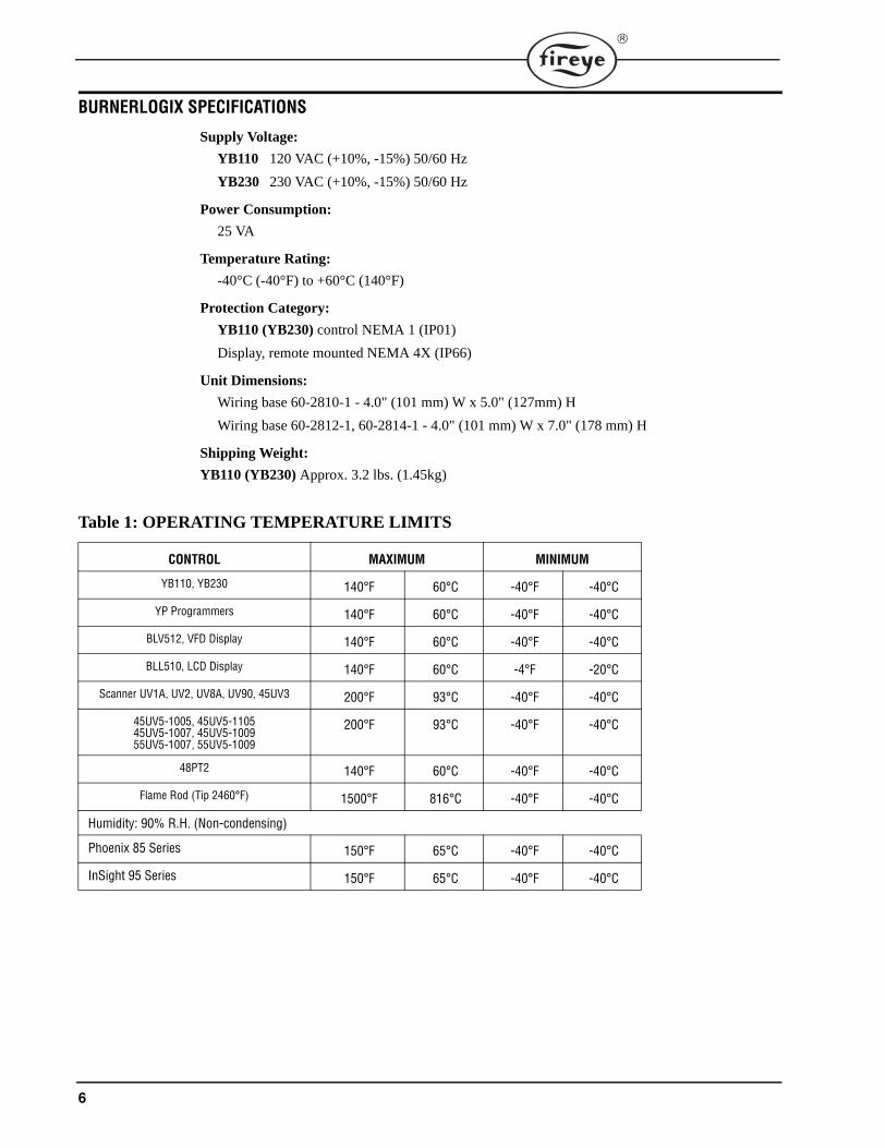
BURNERLOGIX SPECIFICATIONS
Supply Voltage:
YB110 120 VAC (+10%, -15%) 50/60 Hz
YB230 230 VAC (+10%, -15%) 50/60 Hz
Power Consumption:
25 VA
Temperature Rating:
-40°C (-40°F) to +60°C (140°F)
Protection Category:
YB110 (YB230) control NEMA 1 (IP01)
Display, remote mounted NEMA 4X (IP66)
Unit Dimensions:
Wiring base 60-2810-1 - 4.0" (101 mm) W x 5.0" (127mm) H
Wiring base 60-2812-1, 60-2814-1 - 4.0" (101 mm) W x 7.0" (178 mm) H
Shipping Weight:
YB110 (YB230) Approx. 3.2 lbs. (1.45kg)
Table 1: OPERATING TEMPERATURE LIMITS
CONTROL MAXIMUM MINIMUM
YB110, YB230 140°F 60°C -40°F -40°C
YP Programmers 140°F 60°C -40°F -40°C
BLV512, VFD Display 140°F 60°C -40°F -40°C
BLL510, LCD Display 140°F 60°C -4°F -20°C
Scanner UV1A, UV2, UV8A, UV90, 45UV3 200°F 93°C -40°F -40°C
45UV5-1005, 45UV5-110545UV5-1007, 45UV5-100955UV5-1007, 55UV5-1009
200°F 93°C -40°F -40°C
48PT2 140°F 60°C -40°F -40°C
Flame Rod (Tip 2460°F) 1500°F 816°C -40°F -40°C
Humidity: 90% R.H. (Non-condensing)
Phoenix 85 Series 150°F 65°C -40°F -40°C
InSight 95 Series 150°F 65°C -40°F -40°C

7
®
Table 2: LOAD RATINGS
Combination of fuel and igniter terminals
Composition of each combination
Maximum connected load must not exceed 2000 VA
ELECTRICAL RATINGS
VA ratings (not specified as pilot duty) permit the connection of transformers and similar deviceswhose inrush current is approximately the same as their running current.
VA Pilot Duty ratings permit the connection of relays, solenoid valves, lamps, etc. whose total oper-ating load does not exceed the published rating and whose total inrush current does not exceed 10times the rating.
Running and locked rotor ratings are intended for motors. VA and VA Pilot Duty loads may be addedto a motor load provided the total load does not exceed the published rating.
Terminal Typical Load A. Maximum Rating@120V-50/60 Hz
B. Maximum Rating @230V-50/60 Hz
C. Alternate Rating
M Burner/Blower Motor 9.8 F.L.A. *58 L.R.A.
4.0 F.L.A. *20 L.R.A.
240 VA Pilot Duty (Motor Starter Coil)
10-11-12-X Modulator 125 VA Pilot Duty
A Alarm 50 VA Pilot Duty
Terminal ratings may be selected from either column A or C for 120 VAC or from either column B or C for 30 VAC:(select the rating from the column which best applies to the connected load on that terminal).
* F.L.A. = full load amps; L.R.A = locked rotor amps
Combination No. Pilot FuelTrm 6
MainTrm 7
IgnitionTrm 5
Delayed ValveTrm W
1 C E No Load No Load2 B E No Load No Load3 No Load E No Load B4 E E A No Load5 No Load E A E6 D E A No Load7 D D A D8 No Load D A No Load
A B C D E4.5A Ignition@120 VAC
50 VA Pilot Duty plus 4.5A ignition@
120 VAC
180 VA Ignition plus motor valves with: 660
VA inrush, 360 VA open, 250 VA hold.
2A Pilot Duty
@120 VAC
65 VA Pilot Duty plus Motor valves with: 700 VA open 250 VA hold.
2.2A Ignition@230 VAC
50 VA Pilot Duty plus 2.2A ignition
@230 VAC
1A Pilot Duty
@230 VAC

8
APPROVALS
Underwriters Laboratories Inc.:MCCZ File MP1537Controls, Primary Safety - ListedMCCZ2 File MP1537Controls, Primary Safety - ComponentMCCZ7 File MP1537Controls, Primary Safety Certified for CanadaMCCZ8 File MP1537Controls, Primary Safety Certified for Canada - Component
Factory Mutual: ApprovedAcceptable by: Industrial Risk Insurers (I.R.I.)
CE:Gas AppliancesGas Appliance Directive: 90/396/EECLow Voltage Directive: 73/23/EECEMC Directive: 89/336/EECGASTEC: 0063BT1754
(EN298, 2003; EN230, 2005)
DVGW: Reg. No. NG-2510BT0347
DIN-CERTCO: Reg. No. 5F233/08
CAUTION: Published load ratings assume that no contact will be required to handle inrushcurrent more often than once in 15 seconds. Using control switches, solenoid, relays, etc.which chatter lead to premature failure. Run through a test operation (with fuel shut off)following the tripping of a circuit breaker, a blown fuse, or any known instance of chatteringof any external current consuming devices.
NOTICE: This equipment generates and can radiate radio frequency energy, and if notinstalled and used in accordance with the instruction manual may cause interference toradio communications. It has been tested and found to comply with the limits for a Class Acomputing device pursuant to Subpart J of part 15 of FCC Rules, which are designed toprovide reasonable protection against such interference when operated in a commercialenvironment. Operation of this equipment in a residential area may cause interference inwhich case the user, at his own expense, is required to take whatever measures which may berequired to correct the interference.
9
®
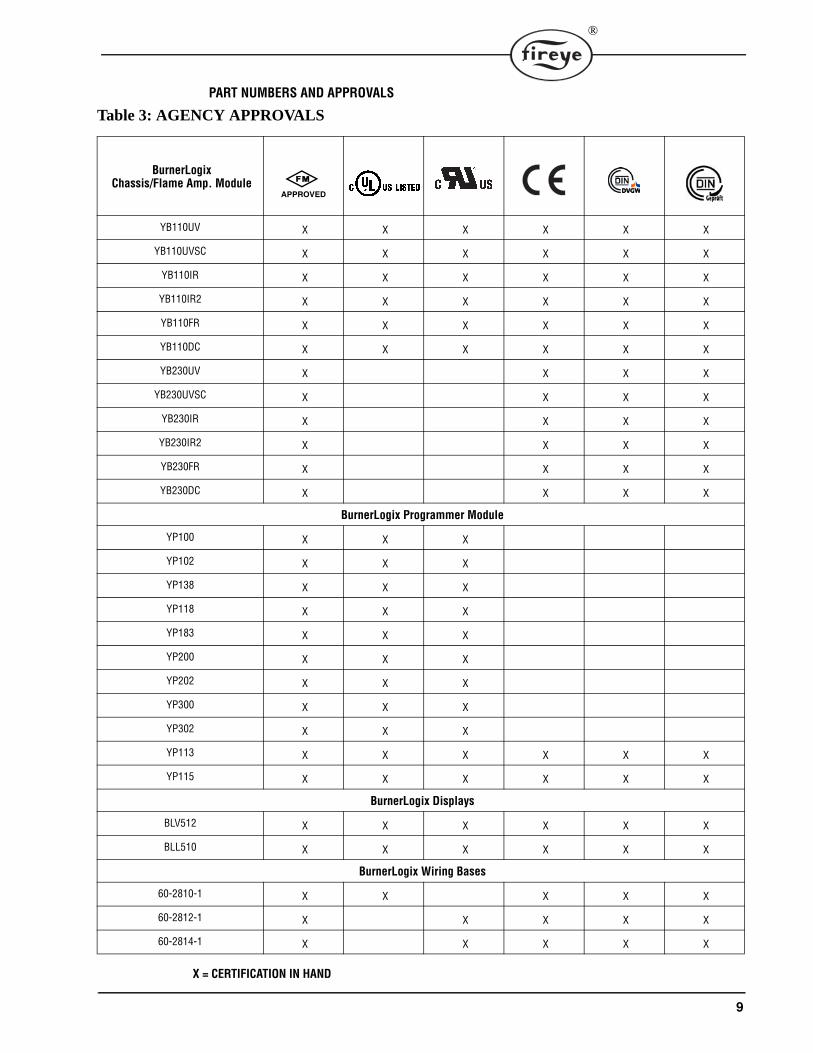
PART NUMBERS AND APPROVALS
Table 3: AGENCY APPROVALS
BurnerLogixChassis/Flame Amp. Module
YB110UV X X X X X X
YB110UVSC X X X X X X
YB110IR X X X X X X
YB110IR2 X X X X X X
YB110FR X X X X X X
YB110DC X X X X X X
YB230UV X X X X
YB230UVSC X X X X
YB230IR X X X X
YB230IR2 X X X X
YB230FR X X X X
YB230DC X X X X
BurnerLogix Programmer Module
YP100 X X X
YP102 X X X
YP138 X X X
YP118 X X X
YP183 X X X
YP200 X X X
YP202 X X X
YP300 X X X
YP302 X X X
YP113 X X X X X X
YP115 X X X X X X
BurnerLogix Displays
BLV512 X X X X X X
BLL510 X X X X X X
BurnerLogix Wiring Bases
60-2810-1 X X X X X
60-2812-1 X X X X X
60-2814-1 X X X X X
X = CERTIFICATION IN HAND
APPROVED

10
Table 4: APPLICABLE BULLETINS
Table 5: ORDERING INFORMATION
Table 6: PROGRAMMER MODULES
Note: All programmers: when used with the YB110DC or YB230DC, the FFRT is 0.2 seconds
Programmers, Non-recycle Operation
YP-1001Programmers, Recycle Operation
Programmers, Non-modulating
Displays BD-5001
Wiring base installation, 60-2810-1 133-676
Wiring base installation, 60-2812-1 133-677
Wiring base installation, 60-2814-1 133-677
BurnerLogix Chassis/Flame Amplifier Module
YB110UV 120 VAC input with UV non self-check amplifier
YB110UVSC 120 VAC input with UV self-check amplifier
YB110IR 120 VAC input with IR auto-check amplifier
YB110IR2 120 VAC input with IR auto-check amplifier (special application only -consult factory)
YB110FR 120 VAC input with flame rectification amplifier
YB110DC 120 VAC input with direct coupled amplifier
YB230UV 230 VAC input with UV non self-check amplifier
YB230UVSC 230 VAC input with UV self-check amplifier
YB230IR 230 VAC input with IR auto-check amplifier
YB230IR2 230 VAC input with IR auto check (special application only-consult factory)
YB230FR 230VAC input with flame rectification amplifier
YB230DC 230VAC input with direct coupled amplifier
BurnerLogix Programmer Modules
YP100 Keypad selectable parameters, non-recycle operation, modulation, open damper proving, 4 second FFRT
YP102 Keypad selectable parameters, non-recycle operation, modulation, open damper proving, 2 second FFRT
YP113 Keypad selectable parameters, non-recycle operation, modulation, open damper proving, 1 second FFRT
YP115 Keypad selectable parameters, non-recycle operation, modulation, open damper proving, 1 second FFRT
YP118 Keypad selectable parameters, non-recycle operation, modulation, open damper proving, indefinite pilot hold, revert to pilot from auto, 1 second FFRT
YP138 Keypad selectable parameters, non-recycle operation, modulation, open damper proving, voltage on terminal 16 is indefinite pilot hold during lightoff, applied voltage on term 16 is revert to pilot from auto, 4 second FFRT
YP183 Same as YP138, except, removal of voltage on terminal 16 will suspend pilot hold during lightoff sequence. Ter-minal W used for purge complete.
YP200 Keypad selectable parameters, recycle operation, modulation, 4 second FFRT
YP202 Keypad selectable parameters, recycle operation, modulation, 2 second FFRT
YP300 Keypad selectable parameters, recycle operation, low fire start, early spark termination, 4 second FFRT
YP302 Keypad selectable parameters, recycle operation, low fire start, early spark termination, 2 second FFRT
11
®
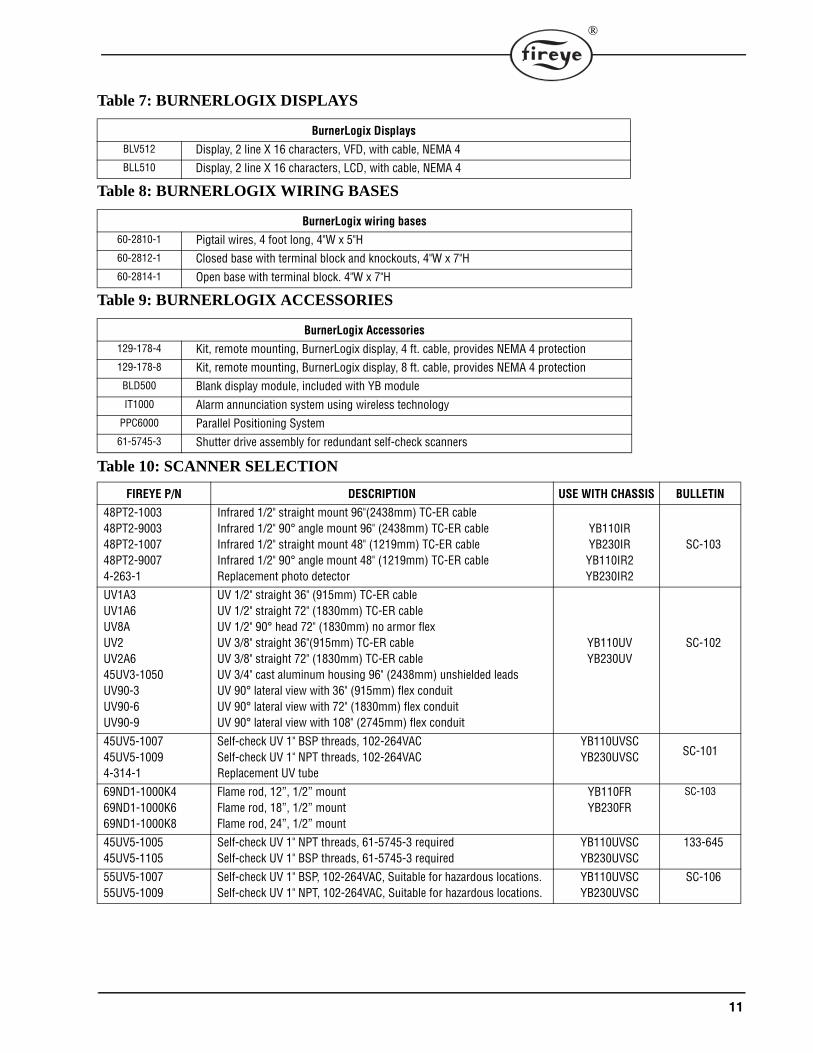
Table 7: BURNERLOGIX DISPLAYS
Table 8: BURNERLOGIX WIRING BASES
Table 9: BURNERLOGIX ACCESSORIES
BurnerLogix DisplaysBLV512 Display, 2 line X 16 characters, VFD, with cable, NEMA 4BLL510 Display, 2 line X 16 characters, LCD, with cable, NEMA 4
BurnerLogix wiring bases60-2810-1 Pigtail wires, 4 foot long, 4"W x 5"H60-2812-1 Closed base with terminal block and knockouts, 4"W x 7"H60-2814-1 Open base with terminal block. 4"W x 7"H
BurnerLogix Accessories129-178-4 Kit, remote mounting, BurnerLogix display, 4 ft. cable, provides NEMA 4 protection129-178-8 Kit, remote mounting, BurnerLogix display, 8 ft. cable, provides NEMA 4 protectionBLD500 Blank display module, included with YB moduleIT1000 Alarm annunciation system using wireless technology
PPC6000 Parallel Positioning System61-5745-3 Shutter drive assembly for redundant self-check scanners
Table 10: SCANNER SELECTION
FIREYE P/N DESCRIPTION USE WITH CHASSIS BULLETIN
48PT2-100348PT2-900348PT2-100748PT2-90074-263-1
Infrared 1/2" straight mount 96"(2438mm) TC-ER cableInfrared 1/2" 90° angle mount 96" (2438mm) TC-ER cableInfrared 1/2" straight mount 48" (1219mm) TC-ER cableInfrared 1/2" 90° angle mount 48" (1219mm) TC-ER cableReplacement photo detector
YB110IRYB230IR
YB110IR2YB230IR2
SC-103
UV1A3UV1A6UV8AUV2UV2A645UV3-1050UV90-3UV90-6UV90-9
UV 1/2" straight 36" (915mm) TC-ER cableUV 1/2" straight 72" (1830mm) TC-ER cableUV 1/2" 90° head 72" (1830mm) no armor flexUV 3/8" straight 36"(915mm) TC-ER cableUV 3/8" straight 72" (1830mm) TC-ER cableUV 3/4" cast aluminum housing 96" (2438mm) unshielded leadsUV 90° lateral view with 36" (915mm) flex conduitUV 90° lateral view with 72" (1830mm) flex conduitUV 90° lateral view with 108" (2745mm) flex conduit
YB110UVYB230UV
SC-102
45UV5-100745UV5-10094-314-1
Self-check UV 1" BSP threads, 102-264VACSelf-check UV 1" NPT threads, 102-264VACReplacement UV tube
YB110UVSCYB230UVSC SC-101
69ND1-1000K469ND1-1000K669ND1-1000K8
Flame rod, 12”, 1/2” mountFlame rod, 18”, 1/2” mountFlame rod, 24”, 1/2” mount
YB110FRYB230FR
SC-103
45UV5-100545UV5-1105
Self-check UV 1" NPT threads, 61-5745-3 requiredSelf-check UV 1" BSP threads, 61-5745-3 required
YB110UVSCYB230UVSC
133-645
55UV5-100755UV5-1009
Self-check UV 1" BSP, 102-264VAC, Suitable for hazardous locations.Self-check UV 1" NPT, 102-264VAC, Suitable for hazardous locations.
YB110UVSCYB230UVSC
SC-106

12
PHOENIX
85UVF4-1QDWR
85UVF4-2QDWR
85IRF4-1QDWR
85IRF4-2QDWR
Phoenix Integrated Scanner, 4 sec FFRT – Ultra-violet with 8-pin electri-cal quick disconnect. FM, UL_CUS approved.Fiber optic version of standard Phoenix Integrated Scanner, 4 sec FFRT – Ultra-violet with 8-pin electrical quick disconnect. FM, UL_CUS approved.Phoenix Integrated Scanner, 4 sec FFRT – Infrared with 8-pin electrical quick disconnect.. FM, UL_CUS approved.Fiber optic version of standard Phoenix Integrated Scanner, 4 sec FFRT – Infrared with 8-pin electrical quick disconnect. FM, UL_CUS approved.
YB110DCYB230DC
CU-11435-318-135-318-2
Mounting flange for Phoenix, 1“ NPTMounting flange for Phoenix, 1“ BSP
59-546-3
59-546-6
59-546-9
59-546-12
59-546-15
59-546-30
59-546-45
59-546-60
59-546-90
8-Conductor 3-meter (9 ft. 10 in.) cable assembly with 8-pin female connector.8-Conductor 6-meter (19 ft. 8 in.) cable assembly with 8-pin female connector.8-Conductor 9-meter (29 ft. 3 in.) cable assembly with 8-pin female connector.8-Conductor 12-meter (39 ft. 4 in.) cable assembly with 8-pin female connector.8-Conductor 15-meter (49 ft. 2 in.) cable assembly with 8-pin female connector.8-Conductor 30-meter (98 ft. 5 in.) cable assembly with 8-pin female connector.8-Conductor 45-meter (147 ft. 7 in.) cable assembly with 8-pin female connector.8-Conductor 60-meter (196 ft. 10 in.) cable assembly with 8-pin female connector.8-Conductor 90-meter (295 ft. 3 in.) cable assembly with 8-pin female connector.
INSIGHT
95IRS2-1, 2
95UVS2-1, 2, 3
95DSS2-1
Enhanced Model InSight Scanner – Infrared with quick disconnect, FM, UL_CUS approved.Enhanced Model InSight Scanner – Ultra-violet with quick disconnect, FM, UL_CUS approved.Enhanced Model InSight Scanner – Dual detector with quick discon-nect, FM, UL_CUS approved.
YB110DCYB230DC
CU-95
60-2692
60-2693
1” NPT mounting flange for InSight Scanner, includes heat insulator 35-127-1.1” BSP mounting flange for InSight Scanner, includes heat insulator 35-127-3.
59-497-020-WR59-497-020C-WR
59-497-020R-WR
59-497-020RC-WR
12-Conductor cable with straight connector (129-164), 20 feet(6 meter)12-Conductor cable with straight connector (129-164C) and flex con-duit adapter, 20 feet(6 meter)12-Conductor cable with right angle connector (129-164R), 20 feet(6 meter)12-Conductor cable with right angle connector (129-164RC) and flex conduit adapter, 20 feet(6 meter)
POWER SUPPLIES
60-2685-2560-2685-50
Power Supply, 24 VDC, 2.0A, 120/240 VAC, 50/60HzPower Supply, 24 VDC, 4.0A, 120/240 VAC, 50/60Hz
CU-118
Table 10: SCANNER SELECTION (Continued)
FIREYE P/N DESCRIPTION USE WITH CHASSIS BULLETIN
NOTE: The Phoenix QDWR models with electrical quick-disconnect have replaced the original WR models equipped with ten feet of captive cable. The QDWR models (with 59-546-X cables) are also suitable for use in Class I Division 2 hazardous areas, thereby eliminating the need for the “EXWR” models.

13
®
FIGURE 1. BURNERLOGIX ORDERING INFORMATION
WIRING BASE60-2810-1PRE-WIRED4 FOOTCOLOR CODED
FRONT VIEW(WITH OPTIONAL DISPLAY INSTALLED)
WIRING BASE60-2814-1OPEN BOTTOMCABINET MOUNT
60-2812-1CLOSED BOTTOMCONDUIT KNOCKOUT
60-2814-1 SHOWN
SIDE VIEW
CHASSIS/AMPLIFIER
120 VAC, 50/60 HzYB110UVYB110UVSCYB110IRYB110FRYB110DC
230 VAC, 50/60 HzYB230UVYB230 UVSCYB230IR
PROGRAMMER MODULE
YP100YP102YP200YP202YP300YP302YP113YP138YP118
DISPLAY MODULE
BLV512 - VACUUM FLUORESCENTBLL510 - LIQUID CRYSTAL
(WITH OPTIONAL PROGRAMMER AND DISPLAY INSTALLED)
14
INSTALLATION PROCEDURE
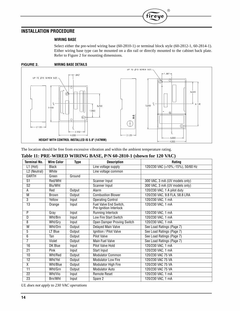
WIRING BASE
Select either the pre-wired wiring base (60-2810-1) or terminal block style (60-2812-1, 60-2814-1).Either wiring base type can be mounted on a din rail or directly mounted to the cabinet back plate.Refer to Figure 2 for mounting dimensions.
FIGURE 2. WIRING BASE DETAILS
The location should be free from excessive vibration and within the ambient temperature rating.
Table 11: PRE-WIRED WIRING BASE, P/N 60-2810-1 (shown for 120 VAC)
UL does not apply to 230 VAC operations
Terminal No. Wire Color Type Description RatingL1 (Hot) Black Line voltage supply 120/230 VAC (+10%,-15%), 50/60 HzL2 (Neutral) White Line voltage commonEARTH Green GroundS1 Red/Wht Scanner Input 300 VAC, 3 mA (UV models only)S2 Blu/Wht Scanner Input 300 VAC, 3 mA (UV models only)A Red Output Alarm 120/230 VAC, 1 A pilot dutyM Brown Output Combustion Blower 120/230 VAC, 9.8 FLA, 58.8 LRA3 Yellow Input Operating Control 120/230 VAC, 1 mA13 Orange Input Fuel Valve End Switch,
Pre-Ignition Interlock120/230 VAC, 1 mA
P Gray Input Running Interlock 120/230 VAC, 1 mAD Wht/Brn Input Low Fire Start Switch 120/230 VAC, 1 mA8 Wht/Gry Input Open Damper Proving Switch 120/230 VAC, 1 mAW Wht/Orn Output Delayed Main Valve See Load Ratings (Page 7)5 LT Blue Output Ignition / Pilot Valve See Load Ratings (Page 7)6 Tan Output Pilot Valve See Load Ratings (Page 7)7 Violet Output Main Fuel Valve See Load Ratings (Page 7)16 DK Blue Input Pilot Valve Hold 120/230 VAC, 1 mA21 Pink Input Start Input 120/230 VAC, 1 mA10 Wht/Red Output Modulator Common 120/230 VAC 75 VA12 Wht/Yel Output Modulator Low Fire 120/230 VAC 75 VAX Wht/Blue Output Modulator High Fire 120/230 VAC 75 VA11 Wht/Grn Output Modulator Auto 120/230 VAC 75 VA22 Wht/Vio Input Remote Reset 120/230 VAC, 1 mA23 Brn/Wht Input Spare 2 120/230 VAC, 1 mA
HEIGHT WITH CONTROL INSTALLED IS 5.8" (147MM)
15
®
INSTALLATION PROCEDURE
WIRING BASE
Install the wiring base where the relative humidity never reaches the saturation point. The Burner-Logix system is designed to operate in a maximum 90% relative humidity continuous, non-condens-ing environment. Do not install the BurnerLogix system where it can be subjected to vibration inexcess of 0.5G continuous maximum vibration. The BurnerLogix system does not use a weathertight enclosure. The standard vertical position is recommended. Allow at least one inch clearancearound the control for service and installation.
1. Wiring must comply with all applicable codes, ordinances and regulations.
2. Wiring must comply with NEC Class 1 (Line Voltage) wiring. )(EU or Local Codes)3. Torque rating on terminal block screws is 4.4 in/lbs to 5.3 in/lbs.4. Limits and interlocks must be rated to simultaneously carry and break current to the ignition
transformer, pilot valve and main fuel valve(s).5. Recommended wire routing of lead wires:
a. Do not run high voltage ignition transformer wires in the same conduit with any otherwires.b. Do not route flame detector lead wires in conduit with line or high voltage circuits. Useseparate conduit where necessary.
6. Maximum wire lengths:a. The maximum lead wire length is 200 ft. (61 meters) to terminal inputs (Operating limits,interlocks, valves, etc.).b. Flame Detector lead wires: see section on flame scannersc. Remote reset: The maximum length of wire is 500 feet (152 meters) to a normally openremote reset push-button, which must remain within sight and sound of the burner.d. Modbus communications: The maximum cable length of wire is 3300 feet (1000 meters)for RS-485.
A good ground system must be provided to minimize the effects of AC quality problems. A properlydesigned ground system meeting all the safety requirements ensures that any AC voltage qualityproblems, such as spikes, surges and impulses have a low impedance path to ground. A low imped-ance path to ground ensures that large currents with any surge voltages follow the desired path toearth ground.
BEFORE INSTALLING THE BURNERLOGIX CONTROL
WARNING: Controls require safety limits using isolated mechanical contacts. Electroniclimit switches can cause erratic operation and must be avoided.
CAUTION: Ensure that electric power is turned off. Refer to SN-100 for recommendedgrounding techniques.
Power to some interlocks (operating controls, air flow switches, modulating circuits, etc.)can be derived from sources other than what is controlling the BurnerLogix.

16
INSTALLING THE YP PROGRAMMER MODULE
FIGURE 3. YP110 PROGRAMMER
The YP programmer module plugs into the side ofthe YB110 (YB230) chassis module. They can onlybe installed in one direction. DO NOT ATTEMPTTO FORCE THE YP PROGRAMMER INTOTHE CHASSIS. Referring to the illustration on theright, align the holes in the YP programmer hous-ing with the posts located within the YB chassis.Push the YP module into the chassis until the YPmodule is flush with the YB housing.
If it is necessary to remove the YP programmermodule from the YB chassis, 2 slots are providedon the top and bottom of the YP housing. A smallscrewdriver can be used to ‘pop’ the programmer from the chassis.
ELECTRICAL CHECKOUT
If either a ground or a short circuit is detected, it must be eliminated before the control is pluggedinto the wiring base and power turned on.
Test the electrical field wiring for short circuits and grounds. The recommended method requires theuse of an ohmmeter set on its lowest resistance scale.
7. Touch the meter probes together and calibrate accurately to ensure a reliable test.8. Disconnect the neutral wire (L2) from the control system at the power source. Clip one meter
test lead to the grounded green wire or to terminal E and with the other probe touch each otherterminal. At no time should the meters show continuity or read 0 ohms.
9. Reconnect the neutral wire (L2) at the power source. Remove the test probe from the groundedterminaland reconnect it to Terminal L2 in the wiring base. With the other probe, touch eachother terminal. It is normal to obtain a resistance reading on the meter at some terminals duringthis test as there are resistive loads (coils, transformers, lamps, etc.) connected whose normalDC resistance may be less than 5 ohms. The test meter should not read zero ohms.
10. With your BurnerLogix installed, measure the voltage from L2 to all other terminals. The read-ing must be zero on all terminals except Ll.
INSTALL BURNERLOGIX INTO WIRING BASE
The BurnerLogix YB chassis/amplifier module contains 2 screws permanently retained into the topand bottom of the housing. The wiring base contains two brass inserts with recessed threads to easethe installation. Line up the printed circuit board spacer located in the YB chassis/amplifier modulewith the alignment tabs located in the wiring base. Firmly push the YB model into the wiring base toassure the connectors mate properly. Tighten the screws into the brass inserts until snug.
YB110
YP100
NOTICE: For installations requiring CE certification:
After installation, the equipment should be protected from general access by means of a cabinetwhich is only accessible with a key or special tool and therefore a clear responsibility whoreplaced the fuse. If the fuse is blown during installation or operation, the control must be sent tothe manufacturer to check.
NOTICE: Restore power for the following test.

17
®
BURNERLOGIX PROGRAMMER SELECTIONAll programmers for the BurnerLogiX Series are designated with the prefix “YP”. The functionaloperation, flame failure response time, purge timings, firing rate motor circuit, trial for ignition tim-ings, recycling function and display messages are determined by the programmer.
Table 12 contains the most common programmers.
Check the programming sequence table for each programming module for the proper explanation ofprepurge timings.
Table 12: BURNERLOGIX PROGRAMMER SELECTION
*FFRT with YB110DC or YB230DC is 0.2 seconds
PTFI*MTFI TIMINGS
The BurnerLogix system provides keypad selectable timings for both PTFI and MTFI. The selec-tions offered can provide 5 or 10 second timing for terminal 5 and 6 or a shortened time for terminal5, allowing for early spark termination. BurnerLogix also provides selectable interrupted or intermit-tent operation for terminal 6.
FIREYE PART
NUMBER
Pre-purge Programming
(Seconds)
Proven High Fire Interlock
(M-8)
Proven Low Fire Interlock
(M-D)
Terminal 6, Interrupted
or Intermittent
Early Spark Termination
PTFI(5/6)
MTFI (5/6)
Running Interlock
(3-P)
* Flame Fail Time (Seconds)
Firing Rate
Motor
SETTINGS SHOWN ARE FACTORY DEFAULT
YP100 30 YES YES INTRP NO 10/10 10/15 Non-recycle 4 YES
YP102 30 YES YES INTRP NO 10/10 10/15 Non-recycle 2 YES
YP138 30 YES YES INTRP NO 10/10 10/15 Non-recycle 4 YES
YP118 30 YES YES INTRP NO 10/10 10/15 Non-recycle 1 YES
YP183 30 YES YES INTRP NO 10/10 10/15 Non-recycle 4 YES
YP112 30 YES YES INTRP NO 5/5 3/5 Non-recycle 2 YES
YP113 30 YES YES INTRP NO 5/5 3/5 Non-recycle 1 YES
YP115 30 YES YES INTRP NO 5/5 3/5 Non-recycle 1 YES
YP200 30 NO YES INTRP NO 10/10 10/15 Recycle 4 YES
YP202 30 NO YES INTRP NO 10/10 10/15 Recycle 2 YES
YP300 30 NO YES INTMT YES 10/10 10/intmt Recycle 4 NO
YP302 30 NO YES INTMT YES 10/10 10/intmt Recycle 2 NO
WARNING: THE INAPPROPRIATE SELECTION OR APPLICATION OF A PROGRAM-MER MODULE CAN RESULT IN AN UNSAFE CONDITION HAZARDOUS TO LIFEAND PROPERTY. The various programmer modules are interchangeable because they pluginto a common YB chassis. Many parameters are configurable through the keypad display.Care must be taken to insure the proper parameters are set. Refer to the appropriate pro-grammer bulletin for appropriate settings. Selection of the programmer module and settingthe various parameters for a particular application must be made by a competent profes-sional, such as a Boiler/Burner technician licensed by a state or government agency, engineer-ing personnel of the burner, boiler or furnace manufacturer (OEM) or in the performance ofduties based on the information from the OEM.
CAUTION: FOR IR MODELS, PRIOR TO VERSION 12, IT IS HIGHLY RECOM-MENDED THAT AN "IR LEARN" OPERATION BE PERFORMED TO GUARANTEERELIABLE OPERATION. REFER TO IR LEARN SECTION FOR MORE INFORMA-TION.
18
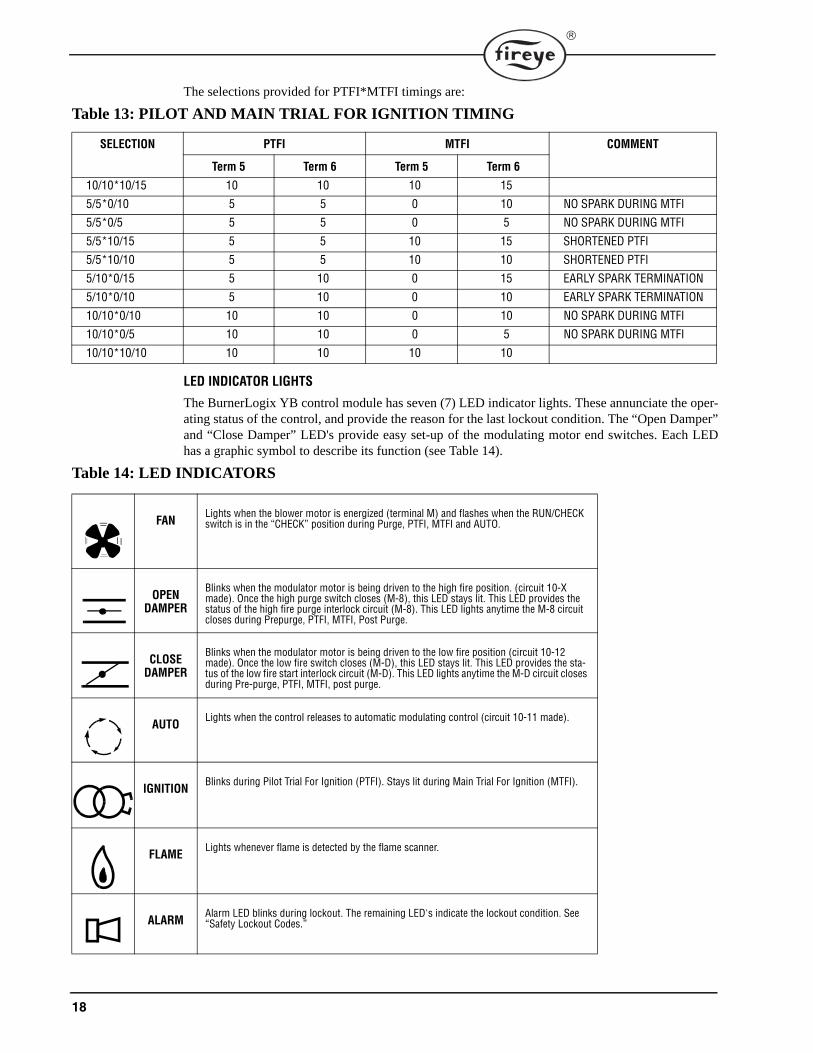
The selections provided for PTFI*MTFI timings are:
Table 13: PILOT AND MAIN TRIAL FOR IGNITION TIMING
LED INDICATOR LIGHTS
The BurnerLogix YB control module has seven (7) LED indicator lights. These annunciate the oper-ating status of the control, and provide the reason for the last lockout condition. The “Open Damper”and “Close Damper” LED's provide easy set-up of the modulating motor end switches. Each LEDhas a graphic symbol to describe its function (see Table 14).
SELECTION PTFI MTFI COMMENT
Term 5 Term 6 Term 5 Term 6
10/10*10/15 10 10 10 15
5/5*0/10 5 5 0 10 NO SPARK DURING MTFI
5/5*0/5 5 5 0 5 NO SPARK DURING MTFI
5/5*10/15 5 5 10 15 SHORTENED PTFI
5/5*10/10 5 5 10 10 SHORTENED PTFI
5/10*0/15 5 10 0 15 EARLY SPARK TERMINATION
5/10*0/10 5 10 0 10 EARLY SPARK TERMINATION
10/10*0/10 10 10 0 10 NO SPARK DURING MTFI
10/10*0/5 10 10 0 5 NO SPARK DURING MTFI
10/10*10/10 10 10 10 10
Table 14: LED INDICATORS
FANLights when the blower motor is energized (terminal M) and flashes when the RUN/CHECK switch is in the “CHECK” position during Purge, PTFI, MTFI and AUTO.
OPEN DAMPER
Blinks when the modulator motor is being driven to the high fire position. (circuit 10-X made). Once the high purge switch closes (M-8), this LED stays lit. This LED provides the status of the high fire purge interlock circuit (M-8). This LED lights anytime the M-8 circuit closes during Prepurge, PTFI, MTFI, Post Purge.
CLOSE DAMPER
Blinks when the modulator motor is being driven to the low fire position (circuit 10-12 made). Once the low fire switch closes (M-D), this LED stays lit. This LED provides the sta-tus of the low fire start interlock circuit (M-D). This LED lights anytime the M-D circuit closes during Pre-purge, PTFI, MTFI, post purge.
AUTOLights when the control releases to automatic modulating control (circuit 10-11 made).
IGNITIONBlinks during Pilot Trial For Ignition (PTFI). Stays lit during Main Trial For Ignition (MTFI).
FLAMELights whenever flame is detected by the flame scanner.
ALARMAlarm LED blinks during lockout. The remaining LED's indicate the lockout condition. See “Safety Lockout Codes.”
19
®
REPLACEABLE FUSE
The following applies only to the YB110 controls operating at 120 VAC, 50/60 Hz:
The chassis/amplifier modules are designed with a field replaceable fuse to protect Terminals 5, 6, 7and W against short circuit loads or mis-wiring. In the event the fuse becomes OPEN, the displaywill indicate CHECK FUSE or the CLOSE DAMPER, AUTO and IGN LED’s lights. An OPEN orblown fuse is a result of an over current condition on Terminals 5, 6, 7, or W. The over current con-dition causing the fuse to OPEN must be resolved before another attempt to apply power.
The fuse is located on the printed circuit board containing the relays. To replace the fuse, removepower from the system and remove the control from its wiring base. Using an appropriate tool,remove the defective fuse and discard. Install a Fireye replacement fuse (P/N 23-197). Re-install theBurnerLogix control in accordance with the installation procedure detailed in a previous section.
The YB230 control contains a non-replaceable fuse and must be returned to the manufacturer forrepair or replacement.
20
OPERATING CONTROL FUNCTIONS1. Operating Controls: Pressure or temperature activated, the operating control closes, causing
the burner start-up sequence to begin. When the operating control opens, the burner shuts off.The operating control is connected in the L1-3 circuit on the wiring base.
2. Limit Switches: These are pressure, water level or temperature activateda. Recycle — To stop the burner when the limit switch opens and restart it when the limit switchrecloses, recycle limit switches connected between Terminals L1 and 3.b. Non-Recycle —when it is necessary to stop the burner when the limit switch opens and pre-vent it from starting until both the limit switch recloses and the manual reset is activated, theyare connected between terminals 3 and P.
3. Fuel Valve End Switch Interlock: This is an integral switch mounted on the main fuel valveand activated by the valve stem. It is connected between Terminal L1 & 13. The fuel valve endswitch interlock prevents a burner start-up if the valve stem is not in the “valve closed” position.This interlock must remain closed while in STANDBY and until the start of PTFI.
4. Purge Interlock: A firing rate motor linkage position switch or a differential air-pressureswitch, that proves a maximum purge air flow rate. It is connected between Terminals M and 8.The purge interlock proves that the air damper is fully open and purge air flow rate is at maxi-mum during the purge.
5. Running Interlocks: These are air flow switches, high and low fuel pressure switches, oil tem-perature switches, atomizing media pressure switches, and excess smoke density controls. Theseinterlocks prove proper conditions for normal operation of the burner. They are wired in seriesand connected between Terminals 3 and P.
6. Low Fire Start Interlock: A firing rate motor linkage position switch or a damper positionswitch, proves both the linkage and dampers are in their proper positions to begin burner lightoff. This switch is connected between Terminals M and D.
SETTING PROGRAMMER PARAMETERSTo change the factory default parameters stored in the programmer module an optional keypad/dis-play (BLV512 or BLL510) is required. All configurable parameters are stored within the PRO-GRAM SETUP sub-menu. The keypad/display module provides tactile feedback keys that are usedto access the sub-menus inherent in the BurnerLogix system.
The BurnerLogix display has 2 lines with 16 characters per line. The default display top line showsthe current operating status. This includes the current point in the burner sequence followed by theparameter pertaining to that point in the sequence, such as time or the flame signal level. The bottomline displays the current operating status. The BurnerLogix display also provides the historical infor-mation stored in the control’s memory such as burner hours, cycles, lockouts and system hours. Theremainder of the display items are menus with sub-menus indicated by a right facing arrow >. Thesub-menus indicate the current value of the selected item and in some cases can be modified to suitthe application.
NOTICE: All programmed settings become permanent after 8 hours of main burner (Terminal 7) on time.
STANDBY PROGRAM SETUP >

21
®
FIGURE 4. KEYPAD DESCRIPTION
The NEXT key is used to scroll down through the variousmenus. It is used to increment in the modify mode. TheBACK key is used to scroll up through the menus. It is alsoused to decrement the value when in the modify mode. Usethe MODE key to enter a sub-menu when the displayeditem indicates a sub-menu with a right facing arrow >, andexit the sub-menu and move on to the next main menu
item. Use the RESET/MDFY key to reset the BurnerLogix from a lockout condition, force a recycleof the programmer, indicate to the system the value displayed is to be modified or when done withthe modification.
FIGURE 5. BURNERLOGIX MENU STRUCTURE
BNR LOCKOUTS
BNR CYCLES
START HERE
Scrolls through menu, clockwise
Keypad Legend
PROGRAM SETUP >
SYS HOURS
STANDBYL1 - 3 OPEN
BNR HOURS
MODE STANDBYPROGRAMMER YP100
LOCKOUT HISTORY >
MODE LO #XX PTFI
SYSTEM INFO >
MODE STANDBYAVG. PILOT FLM. 42
NEXT
Scrolls through menu, counter-clockwiseBACK
Provides access to Sub-MenuMODE
Provides reset of control if lockoutMODIFYRESET
or Exits Sub-Menu
Provides recycle of controlAllows parameter to be modified/saved
FLAME FAIL

22
PROGRAM SET UP SUB-MENUThe sub-menu "PROGRAM SETUP" allows the user to review the various operational settings ofthe programmer module (e.g. programmer type, purge timing, etc.) and in some instances modify theoperational parameters to suit the application requirement. Use the MODE key to enter and exit thesub-menu. Use the NEXT and BACK keys to scroll through the menu and change the operationalparameter.
FIGURE 6. MAIN MENU
PMDFY TO CHANGE
FLM FAIL TIME 4 SEC
AMP IR
PROGRAMMER YP100
DO IR LEARN NO
LOCK SETTINGS NO
START HERE
MODE
PROVE 3-P OPEN N
MDFY TO CHANGECOUNT METHOD DOWN
MDFY TO CHANGEPURGE 0:30
UNIT ADDRESS 1
BAUD RATE 9600
PROVE M-D TFI NO
M-D WAIT 10m YES
POST PURGE 0:15
PROVE M-D OPEN NO
PROVE M-8 OPEN NO
TERMINAL 6 INTRP
PTFI * MTFI TIMING
FROM MAIN MENU LOOP
PRESS KEY FROM MAIN MENU LOOP
MODEPRESS KEY AT ANYTIME TO EXIT SUB-MENU
Note:YB110IR prior toversion 12 only

23
®
Table 15: MODIFIABLE PARAMETERS LOCATED IN PROGRAM SETUP MENU
LEGEND: Shaded parameters not affected by 8 hour burn-in or LOCK SETTINGS.
TO VIEW AND MODIFY A PROGRAMMABLE PARAMETER:
Use the NEXT or BACK key to scroll to PROGRAM SETUP. Press the MODE key to enter the sub-menu showing all program setup parameters. Pressing the MODE key while in the sub-menu exitsthe sub-menu, and the next main menu item is displayed. While in the sub-menu, pressing the NEXTkey scrolls forward through the sub-menu. Pressing the BACK key scrolls backward through thesub-menu. When a modifiable parameter is displayed, the top line indicates MDFY TO CHANGEwhile the bottom line indicates the current item and its current value. Pressing the RESET/MDFYkey allows you to display the parameter you want to modify. The item modified moves to the top linewhile its value remains on the bottom line. Infrequently, the top line indicates MDFY TO SAVE. Usethe NEXT or BACK keys to select the value to suit the application. When done, press the RESET/MDFY to save the changed value to memory.
Refer to SYSTEM INFO Sub Menu, page 35, for language selection.
Parameter Factory Default Range DescriptionPurge time 00:30s 0:00s – 60:00m, 1 second
increments.0:00s-60:00m, YP1130:00s-60:00m, YP115(0:00s - 60:00m in YP3XX)
Applies to open damper purge time in YP1XX and YP2XX pro-grammers and low fire start time in YP3XX programmers
Note: 0 sec purge requires a display with Engr code 9 or higher and chassis Engr code of 11 or higher
Count method DOWN UP, DOWN Time counts UP to final value or DOWN to zero from starting value. This setting will apply to all timer values.
Prove 3-P open at start
NO YES, NO Prevents jumped terminals. Requires the 3-P circuit to be open at the start of a cycle.
PTFI*MTFI timing 10/10*10/15YP113 = 5/5*3/5
See chart on page 18 Applies to terminals 5 and 6 operation during PTFI and MTFI.
Terminal 6 interrupted or intermittent
INTRP INTRP, INTMT Provide interrupted or intermittent operation on terminal 6.
Prove M-8 open NO YES, NO If YES, M-8 must be open at start of open damper purge period. (YP1XX Series only).
Prove M-D open NO YES, NO If YES, M-D must be open at end of open damper purge period. Does not apply to YP3XX Series.
Post purge 0:15 0:00s - 4:00m, 1 second increments.
Selects Post Purge time
3-P Recycle YES YES, NO Applies to YP3XX series only. Allows non-recycle operation of 3-P circuit.
M-D WAIT 10m YES YES, NO Select YES for lockout on M-D open for 10 minutes. Select NO for indefinite wait for M-D to close. This wait time applies prior to pilot trial for ignition.
PROVE M-D TFI NO YES, NO Select YES to force lockout on M-D opening during PTFI and MTFIBaud rate 9600 4800, 9600, 19200, 38400 Sets communication baud rate
Unit address 00 00-31 Multi-drop requires unique addressing. Lowest address allowed for modbus is 01
Lock Settings NO YES, NO Parameters can be stored to memory before automatic 8 hour store.
DO IR LEARN NO YES, NO Select YES to activate IR LEARN process. See IR operation.IR LEARN feature does not exist for display version 10 or newer
NOTICE: All programmed settings become permanent if the BurnerLogix system has beenpowered continuously and 8 hours of main burner (terminal 7) on time has been accumu-lated. If the AC power is removed prior to accumulating 8 hours of main burner on time,the system burn-in time clock is reset to zero. It is not necessary for the main burner on timeto be continuous. The BurnerLogix accumulates burner on time in seconds. If necessary, theprogrammed settings can be made to become permanent anytime before the required 8hours of main burner on time through the use of the optional keypad and the LOCK SET-TINGS option under the PROGRAM SETUP sub menu.

24
FLAME SCANNERS
FIGURE 7. FLAME SCANNERS
INSTALLATION - UV SCANNERS
Where possible, obtain the burner manufacturer’s instructions for mounting the scanner. This infor-mation is available for most standard burners. The scanner mounting must comply with the follow-ing general instructions:
1. Position the UV1A, UV2 scanner within 30 inches of the flame to be monitored; the 45UV5within 72 inches, closer if possible.
2. Select a scanner location that remains within the ambient temperature limits of the UV Scanner.If cooling is required, use an insulating coupling (Fireye #35-69 for UV1A, UV2 Scanners, #35-127-1 for 45UV5) to reduce conducted heat.
3. The UVlA, UV2, 45UV5 Scanners are designed to seal off the sight pipe up to 1 PSI pressure.Higher furnace pressures should be sealed off. To seal off positive furnace pressure up to 100PSI for UV1A, UV2 Scanners, install a quartz window coupling (#60-1257) For 45UV5 Scan-ners, use #60-1100 coupling. Add cooling air to reduce the scanner sight pipe temperature.
4. Install the scanner on a standard NPT pipe (UV1A: 1/2", UV2: 3/8", 45UV5: 1") whose positionis rigidly fixed. If the scanner mounting pipe sights through the refractory, do not extend it morethan halfway through. Swivel flanges are available if desired (#60-302 for UV1A, UV2 Scan-ners, #60-1664-3 for 45UV5). The sight pipe must permit an unobstructed view of the pilot and/or main flame, and both pilot and main flames must completely cover the scanner field of view
FIGURE 8. AIMING YOUR SCANNER.
CAUTION: The UV1A, UV2, UV8A, UV90 and 45UV3 flame scanners and associatedamplifier module are non-self checking UV systems and must only be applied to burnersthat often cycle (e.g.: a minimum of once per 12 hours) in order for the safety checking cir-cuit to be exercised. If component checking is required during burner operation for con-stantly fired burners, use the self-checking ultra-violet flame scanners (45UV5, 55UV5) withthe associated amplifier modules (YB110UVSC), the infrared flame scanner (48PT2) withassociated Auto Check amplifier (YB110IR), or integrated scanners (Phoenix, InSight II orInSight with associated amplifier (YB110DC).
SCANNER MUST HAVE UNOBSTRUCTEDVIEW OF FLAME
NOT THIS NOT THIS BUT THIS
FLAME MUST COMPLETELY COVERSIGHT OPENING
NOT THIS NOT THIS BUT THIS
25
®
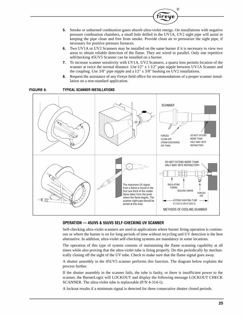
5. Smoke or unburned combustion gases absorb ultra-violet energy. On installations with negativepressure combustion chambers, a small hole drilled in the UV1A, UV2 sight pipe will assist inkeeping the pipe clean and free from smoke. Provide clean air to pressurize the sight pipe, ifnecessary for positive pressure furnaces.
6. Two UV1A or UV2 Scanners may be installed on the same burner if it is necessary to view twoareas to obtain reliable detection of the flame. They are wired in parallel. Only one repetitiveselfchecking 45UV5 Scanner can be installed on a burner.
7. To increase scanner sensitivity with UV1A, UV2 Scanners, a quartz lens permits location of thescanner at twice the normal distance. Use l/2" x 1 l/2" pipe nipple between UV1A Scanner andthe coupling. Use 3/8" pipe nipple and a l/2" x 3/8" bushing on UV2 installations.
8. Request the assistance of any Fireye field office for recommendations of a proper scanner instal-lation on a non-standard application.
FIGURE 9. TYPICAL SCANNER INSTALLATIONS
OPERATION — 45UV5 & 55UV5 SELF-CHECKING UV SCANNER
Self-checking ultra-violet scanners are used in applications where burner firing operation is continu-ous or where the burner is on for long periods of time without recycling and UV detection is the bestalternative. In addition, ultra-violet self-checking systems are mandatory in some locations.
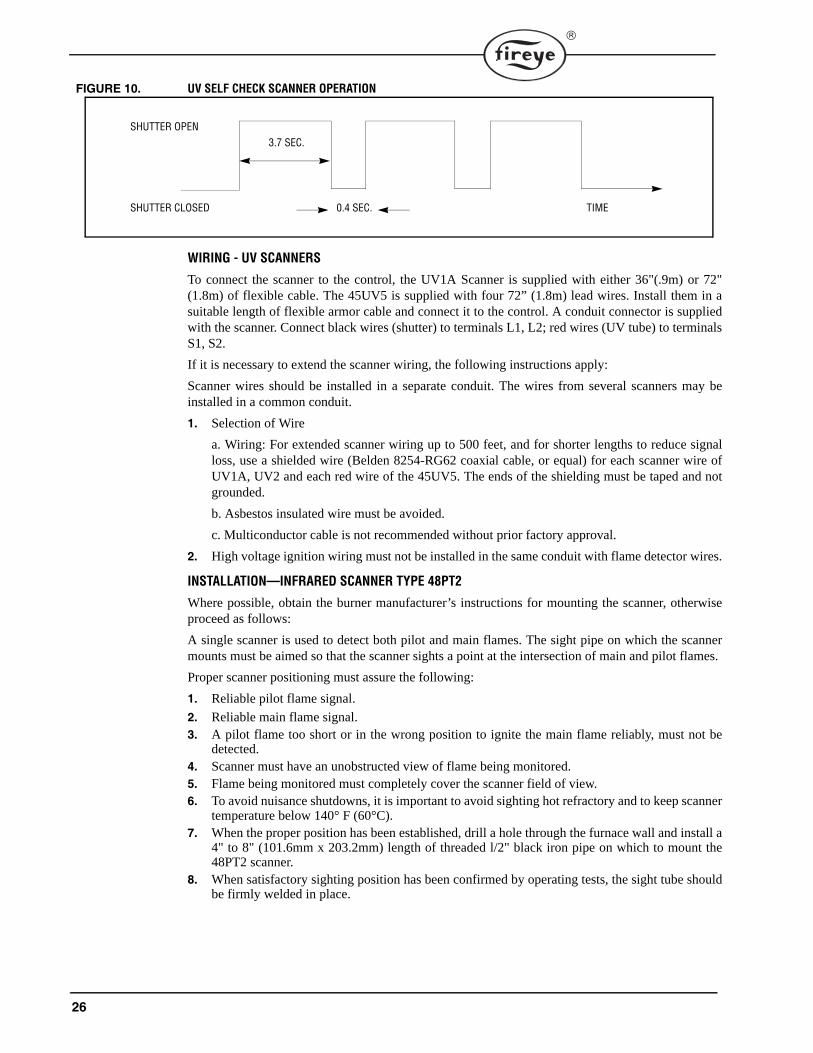
The operation of this type of system consists of maintaining the flame scanning capability at alltimes while also proving that the ultra-violet tube is firing properly. Do this periodically by mechan-ically closing off the sight of the UV tube. Check to make sure that the flame signal goes away.
A shutter assembly in the 45UV5 scanner performs this function. The diagram below explains theprocess further.
If the shutter assembly in the scanner fails, the tube is faulty, or there is insufficient power to thescanner, the BurnerLogix will LOCKOUT and display the following message LOCKOUT CHECKSCANNER. The ultra-violet tube is replaceable (P/N 4-314-1).
A lockout results if a minimum signal is detected for three consecutive shutter closed periods.
The maximum UV signal from a flame is found in the first one-third of the visible flame taken from the point where the flame begins. The scanner sight pipe should be aimed at this area.
DO NOT EXTENDMORE THANHALF-WAY INTOREFRACTORY
SCANNER
FORCEDCLEAN AIR(FROM DISCHARGEOF FAN)
METHODS OF COOLING SCANNER
INSULATINGTUBING
SEALING UNIONFORCED
AIR
EXTEND SIGHTING TUBE6”(152.4) OR 8”(203.2)
DO NOT EXTEND MORE THANHALF-WAY INTO REFRACTORY
26
FIGURE 10. UV SELF CHECK SCANNER OPERATION
WIRING - UV SCANNERS
To connect the scanner to the control, the UV1A Scanner is supplied with either 36"(.9m) or 72"(1.8m) of flexible cable. The 45UV5 is supplied with four 72” (1.8m) lead wires. Install them in asuitable length of flexible armor cable and connect it to the control. A conduit connector is suppliedwith the scanner. Connect black wires (shutter) to terminals L1, L2; red wires (UV tube) to terminalsS1, S2.
If it is necessary to extend the scanner wiring, the following instructions apply:
Scanner wires should be installed in a separate conduit. The wires from several scanners may beinstalled in a common conduit.
1. Selection of Wire
a. Wiring: For extended scanner wiring up to 500 feet, and for shorter lengths to reduce signalloss, use a shielded wire (Belden 8254-RG62 coaxial cable, or equal) for each scanner wire ofUV1A, UV2 and each red wire of the 45UV5. The ends of the shielding must be taped and notgrounded.
b. Asbestos insulated wire must be avoided.
c. Multiconductor cable is not recommended without prior factory approval.
2. High voltage ignition wiring must not be installed in the same conduit with flame detector wires.
INSTALLATION—INFRARED SCANNER TYPE 48PT2
Where possible, obtain the burner manufacturer’s instructions for mounting the scanner, otherwiseproceed as follows:
A single scanner is used to detect both pilot and main flames. The sight pipe on which the scannermounts must be aimed so that the scanner sights a point at the intersection of main and pilot flames.
Proper scanner positioning must assure the following:
1. Reliable pilot flame signal.
2. Reliable main flame signal.3. A pilot flame too short or in the wrong position to ignite the main flame reliably, must not be
detected.4. Scanner must have an unobstructed view of flame being monitored.5. Flame being monitored must completely cover the scanner field of view.6. To avoid nuisance shutdowns, it is important to avoid sighting hot refractory and to keep scanner
temperature below 140° F (60°C). 7. When the proper position has been established, drill a hole through the furnace wall and install a
4" to 8" (101.6mm x 203.2mm) length of threaded l/2" black iron pipe on which to mount the48PT2 scanner.
8. When satisfactory sighting position has been confirmed by operating tests, the sight tube shouldbe firmly welded in place.
SHUTTER OPEN
SHUTTER CLOSED
3.7 SEC.
0.4 SEC. TIME

27
®
FIGURE 11. SCANNER INSTALLATION
WIRING
Attach the cable supplied with the scanner to a junction box. Splice the cable wires to a pair of wires not smaller than #l8. Install the complete run in a separate conduit to the control. Continuous conduit bonding between scanner and the control is mandatory! Scanner may be located up to 100 feet from control. Do not pass scanner wiring through any junction box containing other wires. Do not run other wires through scanner conduit. Asbestos insulated wire must be avoided.
9. To avoid nuisance shutdowns, avoid sighting hot refractory and to keep your scanner tempera-ture low below 140° F (60°C).
10. When the proper position has been established, drill a hole through the furnace wall and install a4" to 8" (101.6mm x 203.2mm) length of threaded l/2" black iron pipe on which to mount the48PT2 scanner.
11. When satisfactory sighting position has been confirmed by operating tests, the sight tube mustbe firmly welded in place.
OPERATION - IR LEARN (for IR Models prior to Version 12 only)
The BurnerLogix IR learn adapts the operation of the amplifier to the actual burner environment.'Out of the box', the BurnerLogix IR system is shipped with its sensitivity and thresholds set to detectmost firing conditions and does not require learning. The purpose of the LEARN process is to maxi-mize reliable flame detection over a wide range of conditions. The learn process sets the optimumvalues for the flame on and flame off thresholds during pilot trial for ignition and the main firingperiod separately. The LEARN process allows the BurnerLogix system to better differentiatebetween real and simulated flame conditions. Simulated flame can be caused by burner throat modu-lation, radiation from the refractory tiles, or steam atomization. The result of this technique of flamedetection assures a positive flame out response for usual or adverse conditions. Although it is notnecessary to perform an IR LEARN, it is suggested this be done as part of the installation process orwhen the 48PT2 scanner is changed.
The type of burner and fuel will affect the amplitude and radiation characteristics of the flame. Gas-eous flames tend to have low amplitude and radiation whereas oil flames have a high amplitude andradiation. On burners having the option to fire both gaseous and oil fuels, it is recommended theLEARN process be performed on the condition that has the lowest signal level. Normally this condi-tion is gas at low fire.
The LEARN process in the BurnerLogix system is initiated through the keypad display module. Themenu item is located under the PROGRAM SETUP menu and is called DO IR LEARN. Refer to thesection titled 'SETTING PROGRAMMER PARAMETERS' for information on setting opera-tional values. Since the default value is NO, the user must modify this value to YES.
MDFY TO CHANGEDO IR LEARN YES
CENTER LINEOF MAIN FLAME
SCANNERLINE-OF-SIGHT
SCANNER TARGETABOVE REFRACTORY
COMBUSTIONCHAMBER
PILOTBURNER
SCANNER
SCANNERSIGHTING TUBE
MAINBURNER
SCANNER MUST NOTSIGHT REFRACTORY
28
The LEARN process is not subject to the 8 hour burn-in and therefore will always be available.If the LEARN process is activated at STANDBY, the LEARN process will involve both pilot andmain flame. If the LEARN process is activated during the main firing period (AUTO) the LEARNprocess will only involve the main flame learn. During this LEARN process in AUTO, the thresholdsfor pilot flame are not affected. It is necessary to have separate learns to adjust for the characteristicsof the flame changing conditions due to changes in background conditions after a long firing period.
Once a LEARN process is activated, it cannot be undone. Also, if a LEARN cannot be com-pleted in the subsequent burner cycle due to burner interruptions or a flame fail, the LEARNprocess will continue to remain active. During PTFI, the LEARN process takes place during thelast 3 seconds of the pilot period and is indicated on the display:
PTFI 80LEARNING FLAME
During AUTO the LEARN process takes place during the first 3 seconds of AUTO and is indicatedon the display
HOLD 80LEARNING FLAME
After the LEARN process is completed the flame signal displayed value is normalized to a value of32.
AUTO 32FLAME SIGNAL
Therefore during the next pilot trail for ignition period the expected value of flame signal should be32.
PTFI 32FLAME SIGNAL
Any increases or decreases in amplitude or radiation may cause the displayed value to increase ordecrease. Should the displayed value continue to decrease, possibly due to changing conditions in theboiler such as a bright background causing a reduction in scanner sensitivity, it is suggested to acti-vate a new DO IR LEARN during AUTO. Without shutting the burner off, scroll to PROGRAMSETUP and in that sub-menu, modify DO IR LEARN to YES. The LEARN function will be acti-vated immediately. [Note: The display will continue to indicate YES even though the LEARN pro-cess is complete. Pressing the up arrow and then down arrow will indicate the updated state of DO IRLEARN.]
An abrupt change in the background radiation (brightness) may be an indication that the firing char-acteristics of the fuel have changed. In oil fired units this may be caused by a sudden interruption inthe oil delivery. The BurnerLogix utilizes this information to make a decision to keep the burner online or force a shut down. A lockout will happen if the background radiation (brightness) changesdownward by 20% in and stays at this level for 1 FFRT. Also, if the detected flame signal averagefalls below 20% of the Learned On value, the burner will also be shut down.
29
®
Keeping the Scanner Cool
Never let your Infrared Scanner (Temperature Limit 140° F) get too hot to grasp comfortably in yourhand. Keep the scanner cool by one or more of the following methods.
1. Use 6" to 8" (152.4mm x 203.2mm) length of pipe between scanner and hot furnace front plate.
2. Use an insulating tube (P/N 35-69) on the end of the iron pipe.3. Force air into the sighting tube. Use Fireye Sealing Union (P/N 60-801).4. Make sure your sighting tube does not extend more than halfway into refractory wall.
INSTALLATION - 69ND1 FLAME ROD
The 69NDl flame rod proves a gas pilot flame and/or main gas flame. It is a spark plug type unit. Itconsists of 1/2' “NPT” mount, a KANTHAL flame rod, a glazed porcelain insulating rod holder anda spark plug connector for making electrical connections. The 69ND1 is available in 12", 18" or 24"(.3m, .46m, .6m) lengths.
The flame rod may be located to monitor only the gas pilot flame or both the gas pilot and main gasflames. Mount it with a l/2" “NPT” coupling.
The following instructions should be observed:
1. Keep your flame rod as short as possible.
2. Keep your flame rod at least 1/2" from any refractory. 3. Your flame rod must enter the pilot flame from the side so as to safely prove an adequate pilot
flame under all draft conditions.4. If the flame is nonluminous (air and gas mixed before burning), extend the electrode tip at least
1/2" into the flame, but not more than halfway through. 5. If the flame is partly luminous, the electrode tip must extend only to the edge of the flame. It is
not necessary to maintain uninterrupted contact with the flame.6. It is preferable to angle the rod downward to minimize the effect of sagging and to prevent it
from coming in contact with any object.7. An adequate grounding surface for the flame must be provided. The grounding surface in actual
contact with the flame must be at least 4 times greater that the area of the portion of the flamerod in contact with the flame. It is essential to adjust the flame rod and ground area ratio to pro-vide a maximum, signal reading.
Note: Interference from the ignition spark can alter the true signal reading by adding to, or sub-tracting from it. This trend sometimes may be reversed by interchanging the primary wires (line volt-age) to the ignition transformer. This interference can also be reduced by the addition of groundedshielding between the flame rod and ignition spark.
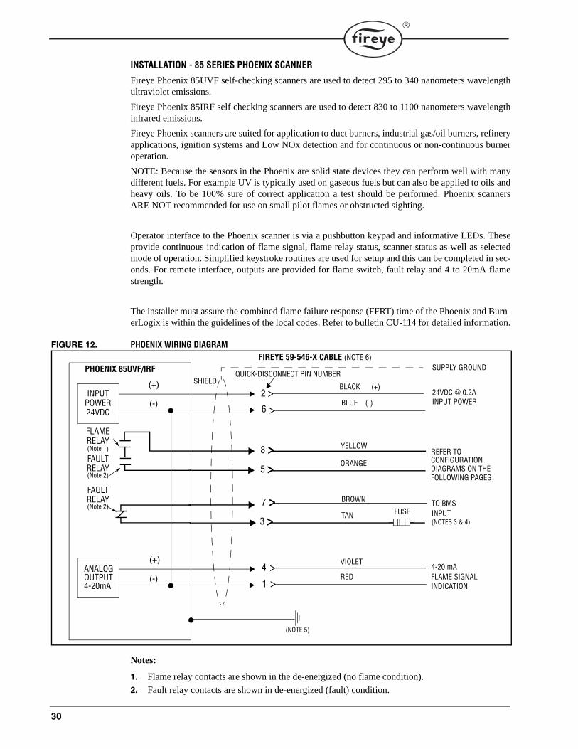
30
INSTALLATION - 85 SERIES PHOENIX SCANNER
Fireye Phoenix 85UVF self-checking scanners are used to detect 295 to 340 nanometers wavelengthultraviolet emissions.
Fireye Phoenix 85IRF self checking scanners are used to detect 830 to 1100 nanometers wavelengthinfrared emissions.
Fireye Phoenix scanners are suited for application to duct burners, industrial gas/oil burners, refineryapplications, ignition systems and Low NOx detection and for continuous or non-continuous burneroperation.
NOTE: Because the sensors in the Phoenix are solid state devices they can perform well with manydifferent fuels. For example UV is typically used on gaseous fuels but can also be applied to oils andheavy oils. To be 100% sure of correct application a test should be performed. Phoenix scannersARE NOT recommended for use on small pilot flames or obstructed sighting.
Operator interface to the Phoenix scanner is via a pushbutton keypad and informative LEDs. Theseprovide continuous indication of flame signal, flame relay status, scanner status as well as selectedmode of operation. Simplified keystroke routines are used for setup and this can be completed in sec-onds. For remote interface, outputs are provided for flame switch, fault relay and 4 to 20mA flamestrength.
The installer must assure the combined flame failure response (FFRT) time of the Phoenix and Burn-erLogix is within the guidelines of the local codes. Refer to bulletin CU-114 for detailed information.
FIGURE 12. PHOENIX WIRING DIAGRAM
Notes:
1. Flame relay contacts are shown in the de-energized (no flame condition).
2. Fault relay contacts are shown in de-energized (fault) condition.
>
INPUT POWER24VDC
FLAMERELAY(Note 1)
FAULT RELAY(Note 2)
FAULT RELAY(Note 2)
(+)
(-)
(+)
(-)
FIREYE 59-546-X CABLE (NOTE 6)
(NOTE 5)
BLACK (+)
BLUE (-)
ORANGE
BROWN
TAN
VIOLET
RED
24VDC @ 0.2A
REFER TO CONFIGURATION DIAGRAMS ON THE
TO BMSINPUT(NOTES 3 & 4)
4-20 mA FLAME SIGNAL
YELLOW
SUPPLY GROUND
SHIELD
ANALOGOUTPUT4-20mA
PHOENIX 85UVF/IRF
>>
>
>>
>>
2
6
8
5
7
4
1
3
QUICK-DISCONNECT PIN NUMBER
INPUT POWER
FOLLOWING PAGES
INDICATION
FUSE

31
®
3. BMS = Burner Management System (by others). Do not use Red as 24 volt ground.4. External 2.0 Amp fuses recommended.5. A safety ground screw is provided on the scanner end plate. An external ground wire must be
installed if line voltage is applied to the relay contacts.
Table 16: PHOENIX SCANNER CABLE COLOR CODE
FIGURE 13. BURNERLOGIX TYB110DC/YB230DC WITH 85UVF4-1QDWR SCANNER
NEW 59-546 CABLE COLOR CODE(Connector Pin No.)
FUNCTION OLD 59-497 CAPTIVE-CABLE COLOR CODEFor reference only
(2) Black 24 vdc Input (+) Black / Red
(6) Blue 24 vdc Input (-) White / Blue
(8) Yellow Flame Relay Contact (n.o.) White / Red
(5) Orange Flame Relay Contact (n.o.) White / Black
(7) Brown Fault Relay Contact (n.c.) Red
(3) Tan Fault Relay Contact (n.c.) Pink
(4) Violet 4-20 ma Analog Output (+) Violet
(1) Red 4-20 ma Analog Output (-) Grey / Red
Shield Drain Wire Earth Ground Shield Drain Wire

32
INSTALLATION - 95 SERIES INSIGHT SCANNERS
Type 95IR contains an infrared flame sensor, responding to infrared radiation from 700 to 1700nanometers wavelength. This sensor is best suited to coal and oil applications.
Type 95UV contains an ultraviolet flame sensor, responding to ultraviolet radiation from 295 to 320nanometers wavelength. This sensor is best suited to gas applications.
Type 95DS (Dual sensor) contains both the infrared and ultraviolet flame sensors described above.This sensor is best suited to multi-fuel applications.
The InSight scanners measure the amplitude of the modulations (the flame “flicker”) that occurwithin the targeted flame. During the scanner set-up procedure, the modulation frequency that yieldsthe best flame ON/OFF discrimination is selected. The appropriate modulation frequency and sensorgain is either manually selected (S1 models), or automatically selected with manual override capabil-ity (S2 models).
The InSight 95IR, 95UV, and 95DS scanners are each available in two models differentiated by fea-ture levels.
The Standard Model S1 has three choices of modulation frequency, adjustable sensor gain, adjust-able flame relay ON/OFF thresholds, 4-20 mA analog signal strength output, fault relay, and twoselectable programmable files to store setpoints (for two different fuels or firing rates).
The Expanded Model S2 adds automatic programming (AutoTune) with manual override capability,21 choices of flame flicker frequency, a total of four selectable programmable files to store setpoints,plus adds remote communication capability via Fireye Windows 95/98/NT user software.
All FIREYE InSight scanner models are powered by 24 Vdc and contain electronic self-checking (nomechanical shutter required). The scanners contain an eight character alpha-numeric LED displayand a four (4) push-button keypad to enable the user to view operating parameters and select set-points.
The Standard Model S1 is best suited to the many applications that do not require the level of sophis-tication, or the remote communications capability of the Expanded Model S2 (e.g. single burner boil-ers and furnaces, duct burners, etc.)
The Expanded Model S2 is best suited to the applications that require the highest level of sophistica-tion and flexibility (addition choices of modulation frequencies, and the time-saving AutoTune func-tion), and remote communications capability (e.g. larger multi-burner boilers and furnaces).
Because of the shorted cable detect algorithm built into the BurnerLogix, it is imperative the propercable be used when employing Insight scanners.
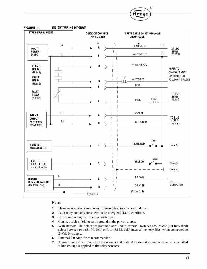
33
®
FIGURE 14. INSIGHT WIRING DIAGRAM
Notes:
1. Flame relay contacts are shown in de-energized (no flame) condition.2. Fault relay contacts are shown in de-energized (fault) condition.3. Brown and orange wires are a twisted pair.4. Connect cable shield to earth ground at the power source.5. With Remote File Select programmed as “LINE”, external switches SW1/SW2 (not furnished)
select between two (S1 Models) or four (S2 Models) internal memory files, when connected to24Vdc (-) supply.
6. External 2.0 Amp fuses recommended.7. A ground screw is provided on the scanner end plate. An external ground wire must be installed
if line voltage is applied to the relay contacts.
TYPE 95IR/95UV/95DS QUICK-DISCONNECTPIN NUMBER
FIREYE CABLE 59-497-020xx-WRCOLOR CODE
A BLACK/RED
B WHITE/BLUE
C WHITE/BLACK
D WHITE/RED
E RED
F PINK
G VIOLET
H GREY/RED
J BLUE/RED
K YELLOW
L BROWN
M ORANGE
(Notes 3, 4)
A
B
(+)
(-)
(+)
(-)
INPUT POWER24VDC
FAULT RELAY(Note 2)
4-20mAOUTPUTReferenced
REMOTEFILE SELECT 1
REMOTEFILE SELECT 2(Model S2 only)
REMOTECOMMUNICATIONS(Model S2 only)
TO COMPUTER
(Note 5)
(Note 5)
TO BMSMETER
TO BMSINPUT
INPUT POWER
SW1
SW2
to Common
(+)
(-)
(Note 6)
(Note 6)
24 VDC
FLAME RELAY(Note 1)
FAULT RELAY(Note 2)
FUSE
(Note 4)
(Note 7)
REFER TOCONFIGURATIONDIAGRAMS ONFOLLOWING PAGESR
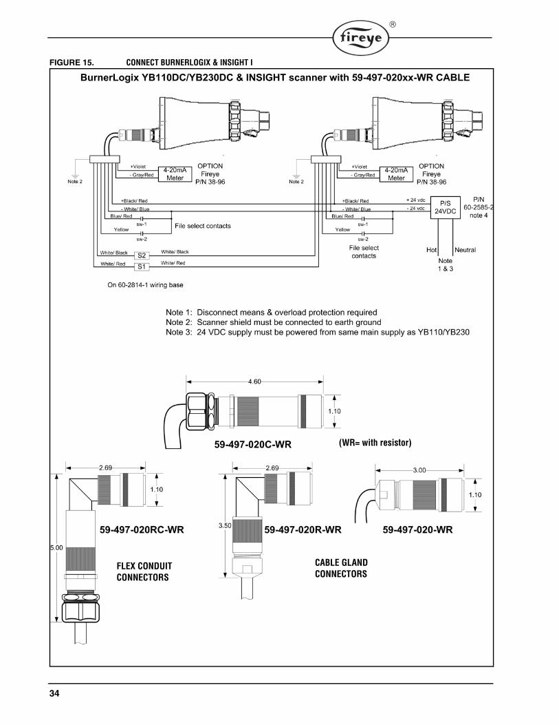
34
FIGURE 15. CONNECT BURNERLOGIX & INSIGHT I
(WR= with resistor)
CABLE GLAND FLEX CONDUIT CONNECTORS CONNECTORS

35
®
SYSTEM INFO SUB-MENUThe sub-menu "SYSTEM INFO" allows the user to review information pertaining to the operationof the control (e.g. average main flame signal strength, status of the high fire and low fire endswitches, etc.). This information can be very helpful when setting the damper linkages on the firingrate motor. The user may also clear the internal burner history (burner hours, cycles and systemhours), number of lockouts and stored lockout information.
Language choices of English, French, Spanish, Dutch German and Swedish are available.
The MODE key is used to enter and exit the "SYSTEM INFO" sub-menu, and the NEXT and BACKkeys are used to advance through the sub-menu.
FIGURE 16. SYSTEM INFO SUB-MENU
SYSTEM OPERATIONThe programmer module determines the functional operation of the Burnerlogix control (e.g. purgetiming, trial for ignition timings, recycle or non-recycle operation, etc.). As illustrated, we are usingthe YP100 Programmer functions and messages associated with the BLL510 display module in thisbulletin. Because the messages change depending upon which YP style programmer is beingused, it is necessary to check the bulletin covering the specific programmer for exact details.Refer to the suggestions shown in this bulletin before proceeding to power the Fireye YB110(YB230) BurnerLogix system. Items such as scanner installation, short circuit tests and safety infor-mation must be carefully reviewed.
P
START HERE
MODE
STANDBYM-D LIMIT OPEN
PRESS KEY FROM MAIN MENU LOOP
STANDBYM-8 LIMIT OPEN
STANDBY
MDFY TO CHANGELANGUAGE ENGLISH
MDFY TO CHANGECLEAR HISTORY NO
MODEPRESS KEY AT ANYTIME TO EXIT SUB-MENU
AVG. MAIN FLM 42
STANDBYAVG. PILOT FLM 42

36
FIGURE 17. YP100 OPERATING SEQUENCE
Terminal PTFI MTFI AUTO Post Purge
STANDBY
3 Operating control
M Cycle complete
Air flow (terminal P) must close within 10 seconds of HFS (M-8) closing
P
Valve closes in one second
13 (POC) Proof of valve closure
Don't care state
X (HI) Purge Complete
12 (LO)
11 (Auto)
PTFI/MTFI times keypad selectable
6 (PV) 15 s
10 s
5 (IGN/PV) 10 s
W (IGN) 5s
7 (MV)
Programmable time begins (30 sec minimum)
8 (HFS)
LFS must be closed Don't care state
D (LFS) 30 s LFS

37
®
START-UP (NORMAL CYCLE)Note: For direct spark ignited oil burners, substitute the words Main-Oil Valve for Pilot Valve.1. Constant 120 VAC must be available to the Ll-L2 terminals only on the wiring base.
2. The operating control circuits (Ll-3) will close, signaling the burner to start its firing sequence.Terminal 13, fuel valve end switch must be closed.
3. The burner/blower motor (terminal M) circuit is energized. The running interlock (limit) circuit(3-P) closes (e.g. all limits, interlocks, etc. are proven).
4. The firing rate motor (Modulator Motor) drives toward the high purge open damper position(10-X circuit made).
5. When the firing rate motor reaches its open damper position, the Hi Purge switch closes (M-8)and the prepurge interval of 30* seconds starts. Assuming countdown method, the BLV512 displays:
If the M-8 circuit does not close, the program holds in this position for ten minutes waiting for itto close. If it does not, the control locks out. If the M-8 circuit is closed at the start of a cycle, thetop line of a display switches to PURGE for 20 seconds.
If the M-8 circuit is not closed at the beginning of a cycle, the top line of a display switches toPURGE for 10 seconds.
6. When the prepurge is completed, the firing rate motor is driven toward the low purge damperposition (10-12 circuit made). The BLV512 displays:
7. Following the minimum 30 second delay (10 second delay on YP113) to permit the firing ratemotor to get to the low fire position, the control waits for the low fire switch (M-D) to close.When it closes, the trial for ignition sequence starts. If after ten minutes, the M-D circuit is notclosed, the control locks out unless selected to wait indefinitely.
8. The trial for ignition period begins with Terminals 5, 6 and W energized simultaneously. This isPTFI (Pilot Trial for Ignition). The BLV512 displays:
This period is ten seconds in duration. Terminal W de-energizes after 5 seconds. Refer toPTFI*MTFI TIMINGS to determine times selected or timings appropriate for the application. Thetest meter jacks on the YB110 (YB230) provides an indication of the flame signal strength. Theflame signal readout is also available on the alpha-numeric display.
PREPRG 00:25HIGH FIRE PURGE
PURGE 00:19HIGH FIRE PURGE
PURGE 00:10HIGH FIRE PURGE
PURGE 00:24LOW FIRE PURGE
PTFI 00:02IGNITION TIMING
MINIMUM ACCEPTABLE 6mA 6-16
NORMAL 7.5 -20mA 20-80
TEST JACKS DISPLAY
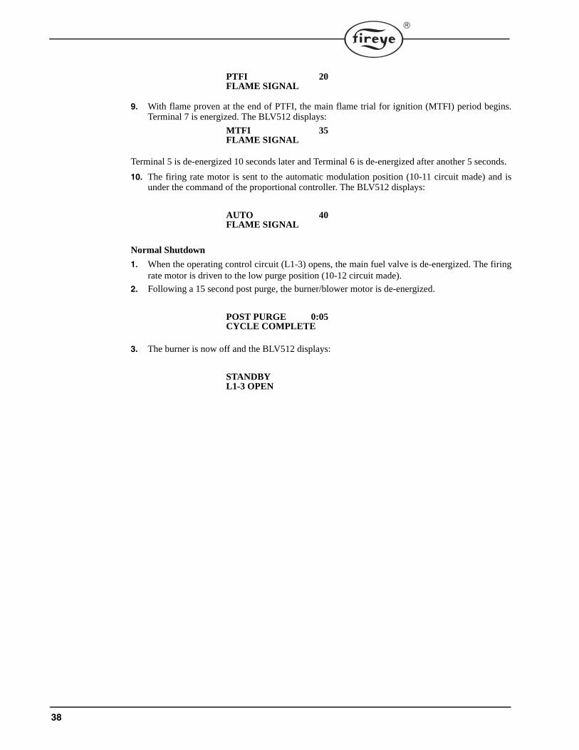
38
9. With flame proven at the end of PTFI, the main flame trial for ignition (MTFI) period begins.Terminal 7 is energized. The BLV512 displays:
Terminal 5 is de-energized 10 seconds later and Terminal 6 is de-energized after another 5 seconds.
10. The firing rate motor is sent to the automatic modulation position (10-11 circuit made) and isunder the command of the proportional controller. The BLV512 displays:
Normal Shutdown
1. When the operating control circuit (L1-3) opens, the main fuel valve is de-energized. The firingrate motor is driven to the low purge position (10-12 circuit made).
2. Following a 15 second post purge, the burner/blower motor is de-energized.
3. The burner is now off and the BLV512 displays:
PTFI 20FLAME SIGNAL
MTFI 35FLAME SIGNAL
AUTO 40FLAME SIGNAL
POST PURGE 0:05CYCLE COMPLETE
STANDBYL1-3 OPEN
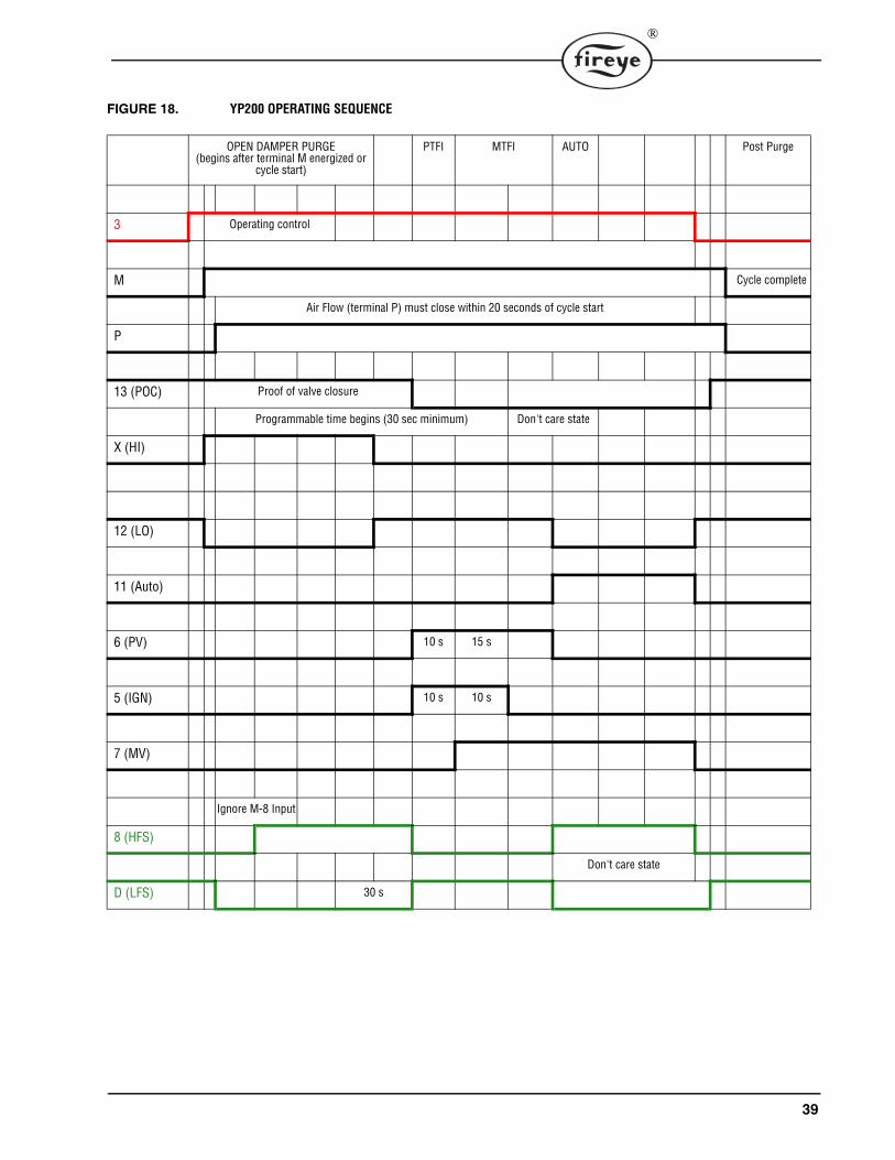
39
®
FIGURE 18. YP200 OPERATING SEQUENCE
OPEN DAMPER PURGE (begins after terminal M energized or
cycle start)
PTFI MTFI AUTO Post Purge
3 Operating control
M Cycle complete
Air Flow (terminal P) must close within 20 seconds of cycle start
P
13 (POC) Proof of valve closure
Programmable time begins (30 sec minimum) Don't care state
X (HI)
12 (LO)
11 (Auto)
6 (PV) 10 s 15 s
5 (IGN) 10 s 10 s
7 (MV)
Ignore M-8 Input
8 (HFS)
Don't care state
D (LFS) 30 s

40
FIGURE 19. YP300 OPERATING SEQUENCE
Programmable Purge Time PTFI MTFI AUTO Post Purge
3 Operating control
Programmable Post Purge
M Cycle complete
P
13 (POC) Proof of valve closure
Don't care state
X (HI)
5 s Ignition
12 (LO)
11 (Auto)
6 (PV) 10 s 15 s Usually Intermittent
5 (IGN) 10 s 10 s
7 (MV)
5 s Delayed Main Valve
W(DV)
8 (HFS)
Don't care state
D (LFS)

41
®
FIGURE 20. BURNERLOGIX WIRING DIAGRAM
10
PV
S2
XD 612 11 WMA
3 P S1L1
E
MODULATOR
VALVEMAINIGN
XFMR
HIGH LOW
AUTOCOMMONPURGE AIR
FLOW SWITCH*LOW FIRESWITCH
RECYCLING INTERLOCKSNON-RECYCLING
RUNNING INTERLOCKS
BURNERLOGIX SYSTEM CONFIGURATION
8
SCANNER TERMINALS
Disconnect
JUMPER
WIRING ARRANGEMENT FOR
SPARK IGNITED OIL BURNERWIRING ARRANGEMENT FOR IGNITION TRANSFORMER
& GAS PILOT VALVE FOR SPARK CUTOFF FEATURE
SET PTFI*MTFI SETTINGS APPROPRIATELY
5 6 5 6 7
IGNITIONTRANSFORMER
GAS PILOTVALVE
IGNITION OILSOLENOID
VALVETRANSFORMER
TYPICAL WIRING ARRANGEMENT FOR PILOT IGNITER
L2
(Applies to YP100 and YP 200 only)
RED
BLACK
45UV5
L1 L2 S1 S2
S2
S1
L2
L1
Caution: All safety limit switches should be approved as limit controls and should be wired directly in the circuit of the Flame Safeguard control. The use of electronic switches to close interlock circuits may cause erratic operation.
YP100, YP113, YP115, YP200 SERIES
T P
L2/N
13
Means and OverloadProtectionRequired
ALARMBLOWER
SUGGESTED WIRING DIAGRAM FOR YP100/YP200 PROGRAMMERS
FUEL VALVE END SWITCH
1. Purge air switch from M to 8 not required for YP200.
2. YP200 programmer recycles on 3-P open.
3. Terminal 6 selectable interrupted/intermittent pilot.
4. Terminal W active first 5 seconds of PTFI (YP100 Series only).
5. See chart on Table 2 for selectable timings (YP100, YP200 only).
Note: When Flame Rod is used jumper S2 to grounding screw in cabinet
Connect terminal E to grounded bonding screw in cabinet.
All wiring must comply with NEC Class 1 (Line Voltage) wiring.
MV
7
PV
5
VALVE PILOT PILOT
VALVE
IMPORTANT:A good earth ground is essential.
R
W
B
POWERSUPPLY
FIRINGRATE
MOTOR
POTENTIOMETERCONTROLLER
COM AUTOLOHI
R W B
T T
10 X 12 11
NOTE: 55UV5 - see bulletin SC-106 for wiring
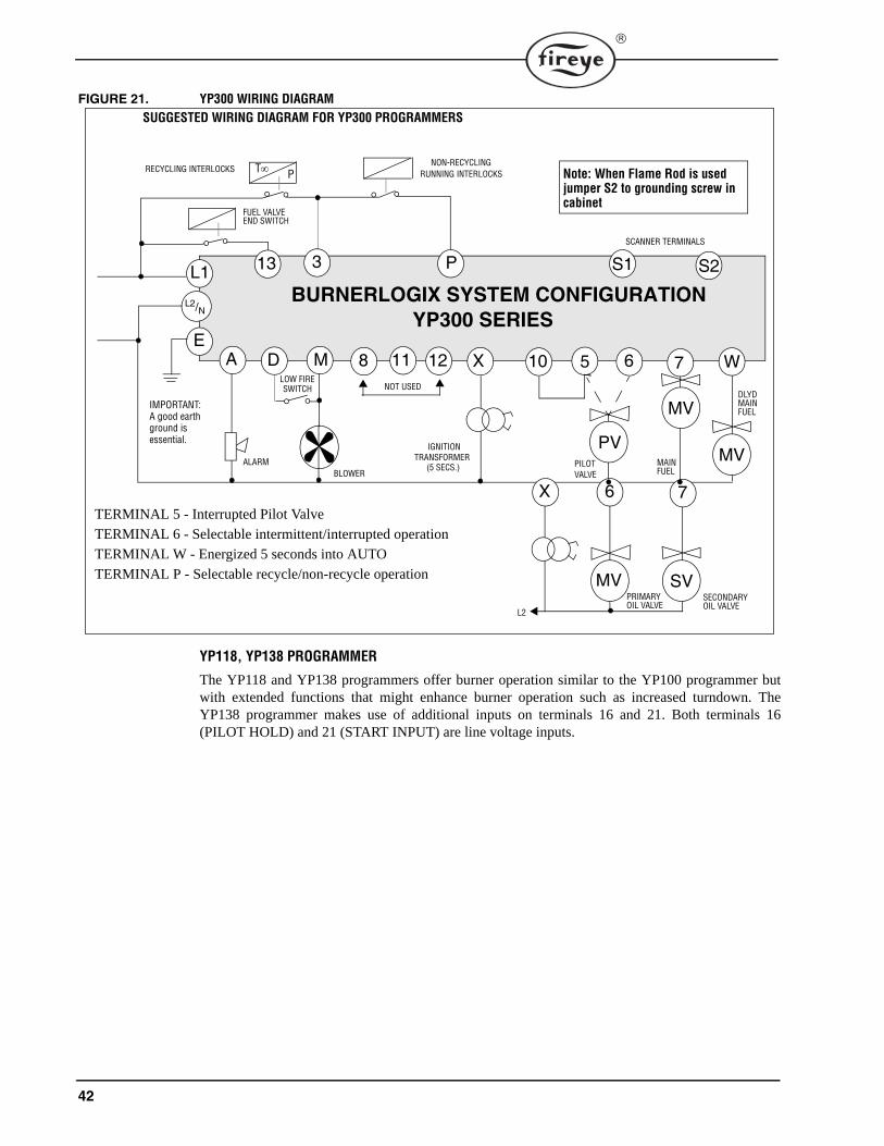
42
FIGURE 21. YP300 WIRING DIAGRAM
YP118, YP138 PROGRAMMER
The YP118 and YP138 programmers offer burner operation similar to the YP100 programmer butwith extended functions that might enhance burner operation such as increased turndown. TheYP138 programmer makes use of additional inputs on terminals 16 and 21. Both terminals 16(PILOT HOLD) and 21 (START INPUT) are line voltage inputs.
X
MV
S2
D 710 6MA
3 P S1L1
E
PILOT MAIN
IGNITIONTRANSFORMER
DLYD
LOW FIRESWITCH
RECYCLING INTERLOCKSNON-RECYCLING
RUNNING INTERLOCKS
BURNERLOGIX SYSTEM CONFIGURATION
8
SCANNER TERMINALS
YP300 SERIES
T P
13
ALARMBLOWER
W
FUEL VALVE END SWITCH
NOT USED
MVPV
11 12 5
FUEL(5 SECS.)
MAINFUEL
MV SV
7X 6
PRIMARY SECONDARYOIL VALVE OIL VALVE
L2
TERMINAL 5 - Interrupted Pilot Valve
TERMINAL 6 - Selectable intermittent/interrupted operation
TERMINAL W - Energized 5 seconds into AUTO
TERMINAL P - Selectable recycle/non-recycle operation
IMPORTANT:A good earth ground is essential.
L2/N
Note: When Flame Rod is used jumper S2 to grounding screw in cabinet
VALVE
SUGGESTED WIRING DIAGRAM FOR YP300 PROGRAMMERS
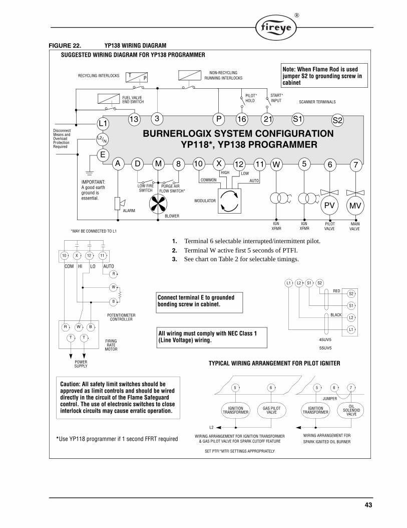
43
®
FIGURE 22. YP138 WIRING DIAGRAM
10
PV
S2
XD 612 11 WMA
3 P S1L1
E
MODULATOR
VALVEMAINIGN
XFMR
HIGH LOW
AUTOCOMMONPURGE AIR
FLOW SWITCH*LOW FIRESWITCH
RECYCLING INTERLOCKSNON-RECYCLING
RUNNING INTERLOCKS
BURNERLOGIX SYSTEM CONFIGURATION
8
SCANNER TERMINALS
Disconnect
YP118*, YP138 PROGRAMMER
T P
L2/N
13
Means and OverloadProtectionRequired
ALARMBLOWER
SUGGESTED WIRING DIAGRAM FOR YP138 PROGRAMMER
FUEL VALVE END SWITCH
Note: When Flame Rod is used jumper S2 to grounding screw in cabinet
IMPORTANT:A good earth ground is essential.
MV
75
XFMR IGN PILOT
VALVE
16 21
START*PILOT* HOLD INPUT
*MAY BE CONNECTED TO L1
Caution: All safety limit switches should be approved as limit controls and should be wired directly in the circuit of the Flame Safeguard control. The use of electronic switches to close interlock circuits may cause erratic operation.
1. Terminal 6 selectable interrupted/intermittent pilot.
2. Terminal W active first 5 seconds of PTFI.3. See chart on Table 2 for selectable timings.
Connect terminal E to grounded bonding screw in cabinet.
All wiring must comply with NEC Class 1 (Line Voltage) wiring.
JUMPER
WIRING ARRANGEMENT FOR
SPARK IGNITED OIL BURNERWIRING ARRANGEMENT FOR IGNITION TRANSFORMER
& GAS PILOT VALVE FOR SPARK CUTOFF FEATURE
SET PTFI*MTFI SETTINGS APPROPRIATELY
5 6 5 6 7
IGNITIONTRANSFORMER
GAS PILOTVALVE
IGNITION OILSOLENOID
VALVETRANSFORMER
TYPICAL WIRING ARRANGEMENT FOR PILOT IGNITER
L2
RED
BLACK
45UV5
L1 L2 S1 S2
S2
S1
L2
L1
55UV5
R
W
B
POWERSUPPLY
FIRINGRATE
MOTOR
POTENTIOMETERCONTROLLER
AUTOLO
R W B
T T
10 X 12 11
HICOM
*Use YP118 programmer if 1 second FFRT required

44
Terminal 21 holds the system indefinitely at the end of low fire start. When opened (off) terminal 21starts pilot trial for ignition. If the count down method is set, at the end of a low fire start period thedisplay indicates:
HOLD 00:00T21 INPUT
During the AUTO or RUN position, terminal 21 is used to force the firing motor to the low fire posi-tion. In this state the display indicates:
HOLD T21 42 top line indicates hold mode with flame signalLOW FIRE SIGNAL
Terminal 16 holds the system in a pilot proving state following the pilot trial for ignition period.After pilot trial for ignition, as determined by the PTFI*MTFI TIMING selection, terminal 5 is de-energized and terminal 6 remains energized. During this state, the system is in a flame proven state.The display indicates:
PILOT 42 flame signal displayedT16 INPUT pilot hold period
Once terminal 16 is released (or de-activated), the Burnerlogix proceeds to the MTFI period inaccordance with the PTFI*MTFI TIMINGS selection. If selected, terminal 5 with the ignitor ener-gizes during MTFI.
Terminal 16 is also used to revert the system back to the pilot proving mode from the AUTO or RUNmode. During AUTO, an active state on terminal 16 starts the steps to revert back to pilot mode. Ondetection of terminal 16, the firing rate motor is commanded to the low fire position and the systemwaits for the low fire start switch (M-D) to close. While in this wait mode the display indicates:
HOLD T16 42 while in AUTO, Terminal 16 closesM-D LIMIT OPEN wait for low fire interlock to close
Once the low fire start switch is detected as closed, terminal 6 is energized to open the pilot valve andterminal 5 is energized to power the ignition transformer.. A 20 second time delay is then imposedwith both the main valve (7) and pilot valve (6) energized. The display indicates:
HOLD T16 42 while in AUTO, M-D detected closedM-D LOW LIMIT wait 20 seconds in this state
At the end of the 20 seconds, the main valve (7) is de-energized and the ignition terminal (5) remainsenergized for the time specified in PTFI*MTFI TIMINGS. Terminal W is energized for 5 seconds.The display indicates:
PTFI 42 flame signal displayedFLAME SIGNAL
Unlike PTFI, this period is a flame proven state and if flame signal is lost for one FFRT, the systemshuts down and locks out. At the end of the selected PTFI time, terminal 5 is de-energized and theBurnerlogix proceeds to the pilot proving period with terminal 6 energized and flame being proven.The display indicates:
PILOT 42 flame signal displayedT16 INPUT pilot hold period
Note: When the main fuel valve is de-energized, its proof-of-closure switch (Fuel Valve End Switch)is expected to close between terminals L1 and 13. If the L1-13 circuit does not close by the time ter-minal 5 is de-energized, the control will shut down and display: "LOCKOUT PILOT, T13 FVESOPEN"
Once terminal 16 is de-energized, the system proceeds to the MTFI period with terminal 7 (mainvalve energized). If selected to be on, terminal 5 with the ignitor becomes energized during MTFI inaccordance with the PTFI*MTFI TIMINGS selection. At the conclusion of the MTFI period and asselected by the PTFI*MTFI TIMINGS selection and terminal 6 as interrupted/intermittent, terminals5 and 6 assume their respective states.
45
®
Notes on operation:
While in AUTO or RUN mode, once the action started by T16 begins, it cannot be reversed byopening T16. At the conclusion of PTFI, if T16 is open, the control advances through MTFI toAUTO.
If START INPUT (T21) and PILOT HOLD (T16) are both active in AUTO, T16 has priority andrevert to pilot starts.
The user shall contact the burner manufacturer to determine if the pilot assembly is ratedfor intermittent operation.?

46
LOCKOUTSWhen a safety shutdown occurs, the control indicates through the LED’s the reason for the lockout.If equipped it displays a lockout message and when in the cycle the lockout occurred. The alarm cir-cuit (Terminal “A”) is energized. The non-volatile memory remembers the status of the control evenif a power failure occurs. By momentarily depressing and releasing the reset button on the control orthe display keypad, the control can be reset. The button must be held down for one second and thenreleased. Very little force is required to do this. Do not press hard.
SAFETY SHUTDOWN1. If the running interlock circuit (3-P) does not close, the control locks out and the blower motor is
de-energized.
2. If the fuel valve end switch or proof of closure switch connected to Terminal 13 opens duringstandby or purge, the control locks out.
3. If the running interlock circuit (3-P) opens during a start-up or firing period, all fuel valves willbe de-energized and the control locks out.
4. If the proven high fire circuit (M-8) has not closed after a ten (10) minute “Hold” period at thestart of prepurge, the control locks out.
5. If the low fire start circuit (M-D) has not closed after a ten (10) minute “Hold” period at the endof prepurge, the control locks out.
6. a.) If PROVE 3-P OPEN is selected as YES, and the 3-P circuit is closed at the start of the oper-ating cycle, the control holds for thirty (30) seconds waiting for the 3-P circuit to open. If, afterthirty (30) seconds, the 3-P circuit does not open, the control locks out.b.) If PROVE M-8 OPEN is selected as YES, and the M-8 circuit is closed at the start of a cycle,the control will hold for thirty (30) seconds for it to open. If, after thirty (30) seconds, the M-8 isstill closed, the control locks out.c.) If PROVE M-D OPEN is selected as YES, and the M-D switch is closed at the end the highfire purge cycle, the control holds for thirty (30) seconds for it to open. If, after thirty (30) sec-onds, the M-D is still closed, the control locks out.d.) If PROVE M-D TFI is selected as YES, the low fire start switch located between terminals M-D must be closed during PTFI and MTFI.
7. If pilot flame is not detected after the pilot trial for ignition period, the pilot valve and ignitiontransformer is de-energized and the control locks out on safety.
8. If main flame is not detected during the main flame trial for ignition period for one FFRT, allfuel valves are de-energized and the control locks out on safety.
9. If the main flame fails during a firing cycle, all fuel valves are de-energized within 1 FFRT andthe control locks out on safety.
10. If flame is detected when the operating control (L1-3) is open, the control waits sixty (60) sec-onds and then locks out if flame is still present. If the operating control closes and flame isdetected during purge, the control drops back to the Standby position and de-energizes theblower motor (Term M). If the flame signal goes away within sixty (60) seconds, the controlproceeds with a normal start-up. If flame signal is still present after sixty (60) seconds, the con-trol locks out.
11. If the fuel valve end switch connected to Terminal 13 is not closed after 5 seconds into postpurge, the control locks out on safety.
PROVING 3-P CLOSED
On cycle start the BurnerLogix proves the 3-P running interlock circuit closed in the followingmanner:
1. At cycle start (L1-3 closes), if the M-8 damper switch is closed, the pre-purge period beginsand the BurnerLogix waits up to 20 seconds for the 3-P circuit to close.
2. At cycle start (L1-3 closes), if the M-8 damper switch is open, the BurnerLogix waits up to 10seconds for the 3-P circuit to close after the M-8 circuit closes. Pre-purge timing begins after theM-8 closes circuit closes.

47
®
Table 17: DIAGNOSTIC MESSAGES
RESETTING THE CONTROL
The BurnerLogix systems contains three methods of reset. These are by: 1. push-button located on the YB chassis/amplifier module2. keypad push-button located on the optional keypad/display module 3. user installed normally open push-button connected from line voltage (L1) to Terminal 22.
Terminal 22 is a line voltage isolated input. Depressing and releasing the reset button is required.
Notes:1. Manual Reset is required following any non-volatile lockout.
2. Depressing and releasing the reset button during a cycle causes the Burnerlogix control to shutthe burner down and recycle.
3. The YP113 and YP115 programmers limit the amount of reset attempts to 5 tries. This internalcounter gets reset to 0 when the control reaches the AUTO state and on every application ofpower.
MESSAGE POSSIBLE CAUSE SOLUTION
CHECK PROGRAMMER
No programmer module plugged into YB chassis/amplifier module
Remove power, insert programmer, press reset to clear fault
Defective programmer module Remove power, replace programmer module
CHECK CHASSIS Relay feedback error caused by bad wiring
Check all wiring, Re-inspect routing of all wires
Programmer module inserted while power is applied
Cycle power, reset control
Defective opto-coupler on the YB chassis/amplifier
Replace YB module
CHECK WIRING Voltage is detected on terminals at improper time
Check system wiring. Measure voltages on input/output terminals
CHECK SCANNER Flame signal detected during shut-ter close time in 45UV5 or 55UV5 scanner
Check power on shutter terminals and/or replace shutter in scan-ner.
Runaway UV tube Replace UV tube, part number 4-314-1
CHECK EXPANSION MODULE
Internal diagnostics within expan-sion module has detected a prob-lem and ceased communications with BurnerLogix control for 3 minutes.
Check that ED580 cable from expansion module to BurnerLogix is plugged in or not damaged, check routing of cable within burner cabinet or check L1-L2 connections to expansion module. Reset control and check STATUS LED on expansion module. Replace YZ300 or YZ320 expansion module or YB110 (YB230) chassis/amplifier module.
Defective or unplugged ED580 cable.
Assure cable is fully inserted in both BurnerLogix control and Expansion module. Check for damage to cable or connectors.
WAITING FOR DATA Communications to/from display Indicates the display is not communicating properly with chassis. Check that the YP programmer is properly inserted. Check that the cable is not defective and is properly inserted into the connectors. In rare instances due to ongoing enhancements to the BurnerLogix family, the display and chassis may not be compatible. Check the date code and engineering code of both sets.
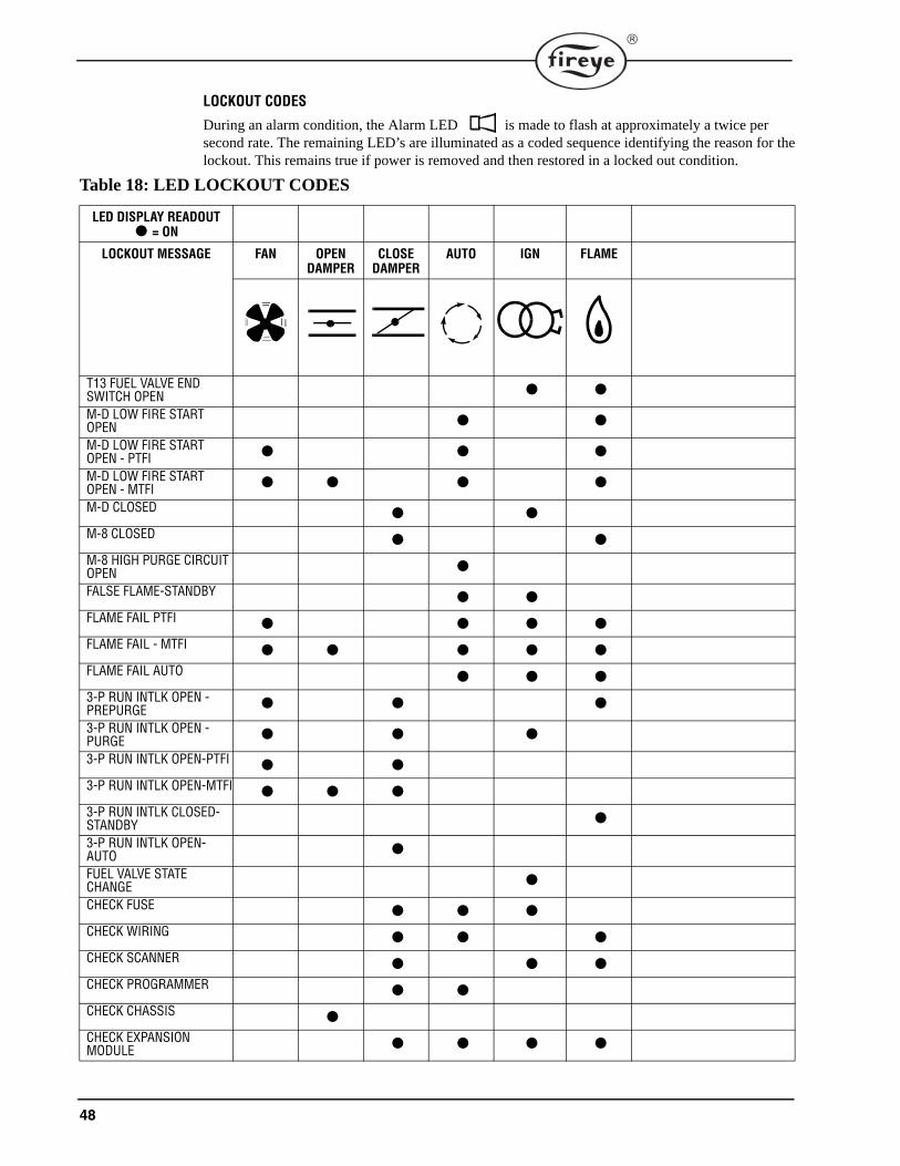
48
LOCKOUT CODES
During an alarm condition, the Alarm LED is made to flash at approximately a twice per second rate. The remaining LED’s are illuminated as a coded sequence identifying the reason for thelockout. This remains true if power is removed and then restored in a locked out condition.
Table 18: LED LOCKOUT CODES
LED DISPLAY READOUT = ON
LOCKOUT MESSAGE FAN OPEN DAMPER
CLOSE DAMPER
AUTO IGN FLAME
T13 FUEL VALVE END SWITCH OPEN M-D LOW FIRE START OPEN M-D LOW FIRE START OPEN - PTFI M-D LOW FIRE START OPEN - MTFI M-D CLOSED M-8 CLOSED M-8 HIGH PURGE CIRCUIT OPEN FALSE FLAME-STANDBY FLAME FAIL PTFI FLAME FAIL - MTFI FLAME FAIL AUTO 3-P RUN INTLK OPEN - PREPURGE 3-P RUN INTLK OPEN - PURGE 3-P RUN INTLK OPEN-PTFI 3-P RUN INTLK OPEN-MTFI 3-P RUN INTLK CLOSED-STANDBY 3-P RUN INTLK OPEN-AUTO FUEL VALVE STATE CHANGE CHECK FUSE CHECK WIRING CHECK SCANNER CHECK PROGRAMMER CHECK CHASSIS CHECK EXPANSION MODULE

49
®
LOCKOUT HISTORY SUB-MENU
The sub-menu "LOCKOUT HISTORY" displays the last ten (10) lockouts, along with the burnercycle and burner hour when the lockout occurred. When the MODE key is pressed, the screen dis-plays the most recent lockout condition and the number of that lockout (e.g. LO #10 represents the10th lockout of that control). The NEXT key displays the Burner Hour, followed by the Burner Cyclewhen the lockout occurred. The NEXT key advances to the next lockout, and repeats the sequencelisted above. The BACK key is used to scroll back up through the sub-menu items. The MODE keyexits the sub-menu.
FIGURE 23. LOCKOUT HISTORY
P
START HERE
MODE
LO #9 PURGE@ BNR HOUR 3
PRESS KEY FROM MAIN MENU LOOP
LO #9 PURGE3-P INTLK OPEN
LO #10 STANDBY@ BNR CYCLE 8
LO #10 STANDBY@ BNR HOUR 3
LO #10 STANDBYT13 FVES OPEN
LO #9 PURGE
LO #1 PTFIFLAME FAIL 3
LO #1 PTFI@ BNR HOUR 1
LO #1 PTFI@ BNR CYCLE 3
MODEPRESS KEY AT ANYTIME TO EXIT SUB-MENU
@ BNR CYCLE 7
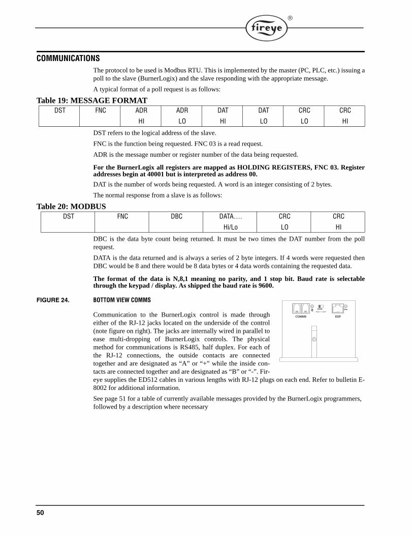
50
COMMUNICATIONSThe protocol to be used is Modbus RTU. This is implemented by the master (PC, PLC, etc.) issuing apoll to the slave (BurnerLogix) and the slave responding with the appropriate message.
A typical format of a poll request is as follows:
Table 19: MESSAGE FORMAT
DST refers to the logical address of the slave.
FNC is the function being requested. FNC 03 is a read request.
ADR is the message number or register number of the data being requested.
For the BurnerLogix all registers are mapped as HOLDING REGISTERS, FNC 03. Registeraddresses begin at 40001 but is interpreted as address 00.
DAT is the number of words being requested. A word is an integer consisting of 2 bytes.
The normal response from a slave is as follows:
Table 20: MODBUS
DBC is the data byte count being returned. It must be two times the DAT number from the pollrequest.
DATA is the data returned and is always a series of 2 byte integers. If 4 words were requested thenDBC would be 8 and there would be 8 data bytes or 4 data words containing the requested data.
The format of the data is N,8,1 meaning no parity, and 1 stop bit. Baud rate is selectablethrough the keypad / display. As shipped the baud rate is 9600.
FIGURE 24. BOTTOM VIEW COMMS
Communication to the BurnerLogix control is made througheither of the RJ-12 jacks located on the underside of the control(note figure on right). The jacks are internally wired in parallel toease multi-dropping of BurnerLogix controls. The physicalmethod for communications is RS485, half duplex. For each ofthe RJ-12 connections, the outside contacts are connectedtogether and are designated as “A” or “+” while the inside con-tacts are connected together and are designated as “B” or “-”. Fir-eye supplies the ED512 cables in various lengths with RJ-12 plugs on each end. Refer to bulletin E-8002 for additional information.
See page 51 for a table of currently available messages provided by the BurnerLogix programmers, followed by a description where necessary
DST FNC ADR
HI
ADR
LO
DAT
HI
DAT
LO
CRC
LO
CRC
HI
DST FNC DBC DATA….
Hi/Lo
CRC
LO
CRC
HI
���������������� ��������
�� ����� ���

51
®
Table 21: MODBUS MESSAGE TABLE
Polling intervals not be less than 200 mSec per request. Requesting data such as burner min-utes, system minutes and burner cycles should be kept at a minimum due to the amount of pro-cessing time required to gather that data.
The MSGN being transmitted is a numerical value and must be interpreted by the communicatingdevice, which actually is an advantage since this can be made to be whatever message text the enduser wants. In other words, it allows for programming custom messages without actually changingthe message in the programmer. Refer to Table 25, for message information.
The BurnerLogix stores its burner on time (7 powered) and system on time (L1 powered) in minutes.For display purposes, the programmer converts this to hours. The information being supplied byModbus will be the actual time in minutes and it is up to the communicating device to do the conver-sion. Since the maximum value stored in the BurnerLogix is 9,999,999 minutes, the maximum valuein hex therefore is 98967FH and comprises two data words. The maximum cycle count is 999,999decimal or F423FH, still two data words.
HOLDING REGISTER
MESSAGEADDRESS
WORD REQUESTED
WORDRESPONSE
VALUE
40001 00 1 STATUS 83 (053H) = RUN;202 (0CAH) = LOCKOUT
40002 01 1 MSGN Current message being displayed (see Table 25)
40003 02 1 GSTAT Defines Timer Type40004 03 1 TIMER Time in seconds40005 04 1 FLAME Flame Signal40006 05 1 LOGSTAT Current logic module, PURGE, PTFI, AUTO
(see Table 24)40007 06 1 INPUTS Input limits state40008 07 1 OUTPUTS Output relays state40009 08 2 SYSMINS System on minutes40011 10 2 BNRMINS Burner on minutes40013 12 2 CYCLES Completed Burner Cycles40015 14 1 LOCKOUT COUNT Stored Lockout Count
40016 15 6LOCKOUT HISTORY Beginning of Last 10 Lockouts
Most Recent Lockout DataReturns complete lockout description of stored lockout
history.
Includes lockout message (1), lockout module (1), @ burner hours (2), and @ burner cycles (2)s
40022 21 6 2nd Most Recent Lockout Data40028 27 6 3rd Most Recent Lockout Data40034 33 6 4th Most Recent Lockout Data40040 39 6 5th Most Recent Lockout Data40046 45 6 6th Most Recent Lockout Data40052 51 6 7th Most Recent Lockout Data40058 57 6 8th Most Recent Lockout Data40064 63 6 9th Most Recent Lockout Data40070 69 6 10th Most Recent Lockout Data40076
40079
75
78
4
40080
40090
79
89
11N/A Reserved for Fireye use
INTERLOCK ANNUNCIATOR40901 900 1 - 3
YZ300 Expansion Module registers(see Table 23)
Returns lower, middle and upper interlock annunciator (YZ300) registers.
40902 901 1 - 2 Returns middle and upper interlock annunciator (YZ300) registers.
40903 902 1 Returns upper interlock annunciator (YZ300) register.
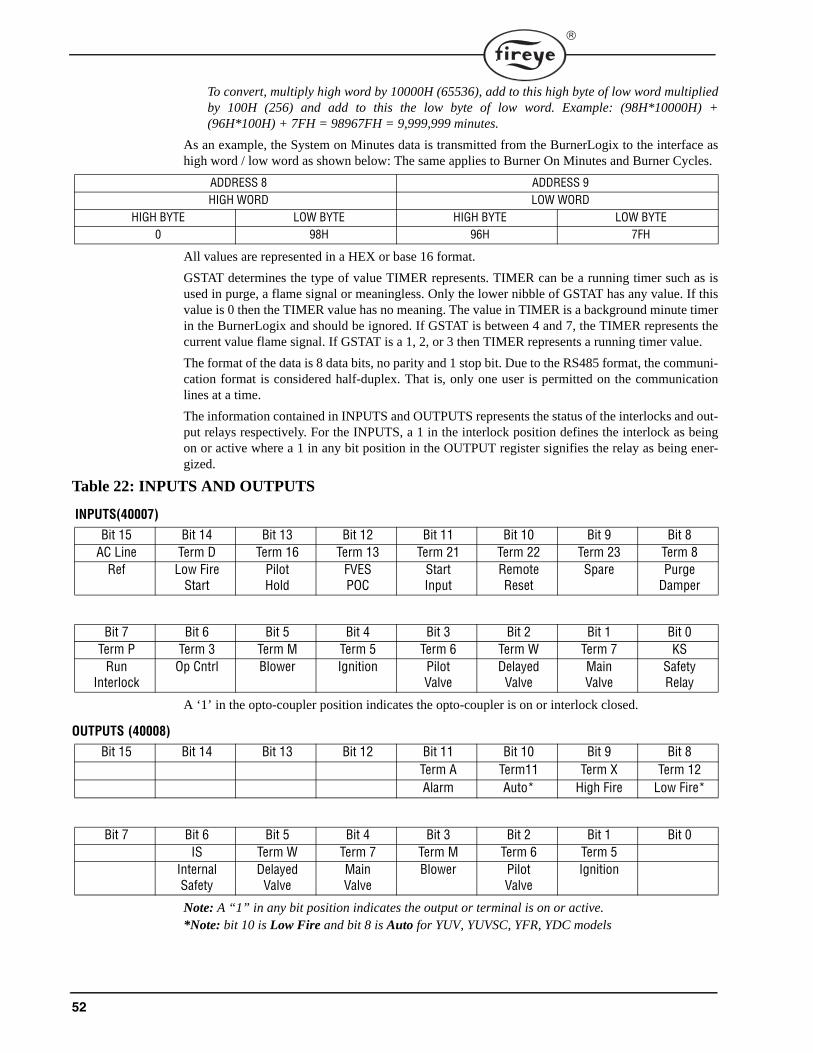
52
To convert, multiply high word by 10000H (65536), add to this high byte of low word multipliedby 100H (256) and add to this the low byte of low word. Example: (98H*10000H) +(96H*100H) + 7FH = 98967FH = 9,999,999 minutes.
As an example, the System on Minutes data is transmitted from the BurnerLogix to the interface ashigh word / low word as shown below: The same applies to Burner On Minutes and Burner Cycles.
All values are represented in a HEX or base 16 format.
GSTAT determines the type of value TIMER represents. TIMER can be a running timer such as isused in purge, a flame signal or meaningless. Only the lower nibble of GSTAT has any value. If thisvalue is 0 then the TIMER value has no meaning. The value in TIMER is a background minute timerin the BurnerLogix and should be ignored. If GSTAT is between 4 and 7, the TIMER represents thecurrent value flame signal. If GSTAT is a 1, 2, or 3 then TIMER represents a running timer value.
The format of the data is 8 data bits, no parity and 1 stop bit. Due to the RS485 format, the communi-cation format is considered half-duplex. That is, only one user is permitted on the communicationlines at a time.
The information contained in INPUTS and OUTPUTS represents the status of the interlocks and out-put relays respectively. For the INPUTS, a 1 in the interlock position defines the interlock as beingon or active where a 1 in any bit position in the OUTPUT register signifies the relay as being ener-gized.
Table 22: INPUTS AND OUTPUTS
INPUTS(40007)
A ‘1’ in the opto-coupler position indicates the opto-coupler is on or interlock closed.
OUTPUTS (40008)
Note: A “1” in any bit position indicates the output or terminal is on or active.*Note: bit 10 is Low Fire and bit 8 is Auto for YUV, YUVSC, YFR, YDC models
ADDRESS 8 ADDRESS 9HIGH WORD LOW WORD
HIGH BYTE LOW BYTE HIGH BYTE LOW BYTE0 98H 96H 7FH
Bit 15 Bit 14 Bit 13 Bit 12 Bit 11 Bit 10 Bit 9 Bit 8AC Line Term D Term 16 Term 13 Term 21 Term 22 Term 23 Term 8
Ref Low FireStart
Pilot Hold
FVES POC
StartInput
RemoteReset
Spare Purge Damper
Bit 7 Bit 6 Bit 5 Bit 4 Bit 3 Bit 2 Bit 1 Bit 0Term P Term 3 Term M Term 5 Term 6 Term W Term 7 KS
Run Interlock
Op Cntrl Blower Ignition PilotValve
DelayedValve
MainValve
SafetyRelay
Bit 15 Bit 14 Bit 13 Bit 12 Bit 11 Bit 10 Bit 9 Bit 8Term A Term11 Term X Term 12Alarm Auto* High Fire Low Fire*
Bit 7 Bit 6 Bit 5 Bit 4 Bit 3 Bit 2 Bit 1 Bit 0IS Term W Term 7 Term M Term 6 Term 5
InternalSafety
DelayedValve
MainValve
Blower PilotValve
Ignition

53
®
Table 23: YZ300
YZ300 LOWER (40901) – REFER TO BULLETIN YZEM-3001
* Terminals 44 and 45 are internally connected
YZ300 MIDDLE (40902) – REFER TO BULLETIN YZEM-3001
* Terminals 49 and 50 are internally connected
* Terminals 53 and 54 are internally connected
YZ300 UPPER (40903) – REFER TO BULLETIN YZEM-3001
* Unused Bits 4-7 will always return 0
FIGURE 25. DEFAULT WIRING FOR YZ300 INTERLOCK ANNUNCIATOR
Bit 7 Bit 0
Term 47 Term 46 Term 44* Term 43 Term 3 Term 42 Term 41 Term 40
Low Oil Temp High Oil Temp
Low Water High Water Aux #3 Aux #2 Aux #1 Op Control
Bit 7 Bit 0
Term 57 Term 56 Term 55 Term 54* Term 52 Term 51 Term 49* Term 48
Aux #4 High Temp High Pres-sure
Aux Gas High Gas Pressure
Low Gas Pressure
Low Atomizing Media
Low Oil Pressure
Bit 7 Bit 0
Term P Term 60 Term 59 Term 58
Unused Unused Unused Unused Air Flow Aux #7 Aux #6 Aux #5
AUXLIMIT #3
AUXLIMIT #2
AUXLIMIT #1
OPERATINGCONTROL
HIGHWATER
LOWWATER
42 41 40
L2/N
HIGH OILTEMP.
LOW OILTEMP
LOW OILPRESS
46 47
AIRFLOW
AUXLIMIT #7
60
AUX LIMIT #6
AUXLIMIT #5
AUXLIMIT #4
HIGHPRESSURE
59585756
43 44
AUXGAS
HIGH GASPRESSURE52
50
LOW GAS PRESSURE51
LOW ATOMMEDIA
48
53
45
OIL SELECT
GAS SELECT49
SIMULTANEOUS FIRING
54HIGHTEMP55
L1
3
EP
See Bulletin YZEM-3001

54
EXPLANATION OF LOGSTAT
LOGSTAT is an indication of what logic module the control is currently operating in during its cycle and is used for diagnostic purposes only. If a lockout occurs the current value of LOGSTAT is stored as part of the lockout information. The message displayed corresponds to the current logic module.
Table 24: LOGSTAT
Logstat represents the current software module the BurnerLogix is currently executing.
The BurnerLogix outputs the current displayed message as well as the historical lockout messages asnumbers. The table below correlates the message number with the actual displayed text message.
LOGIC DISPATCHERVALUE MODULE FUNCTION
DEC HEX1 01H STANDBY Idle state2 02H BLOWER ON 1/2 second period after operating control closes when blower motor is energized3 03H PURGE Open Damper Purge or waiting for air flow and/or high fire switch to close4 04H PURGE Low Fire Purge5 05H PTFI Pilot Trial for Ignition6 06H PTFI Pilot Trial for Ignition for YP3XX programmers7 07H PTFI If PTFI is greater than 5 seconds and early spark termination is not needed8 08H PTFI If PTFI is greater than 5 seconds and early spark termination is needed9 09H PILOT Pilot Hold, YP138 only
10 0AH MTFI Main Trial for Ignition11 0BH MTFI Main Trial for Ignition with terminal 5 de-energized12 0CH AUTO Delayed valve on13 0DH AUTO AUTO14 0EH AUTO On YP138 programmer, hold for 20 seconds with terminals 6 and 7 energized15 0FH AUTO On YP138 programmer, when terminal 21 first energized, wait for M-D to close16 10H POSTPURGE Post Purge17 11H POSTPURGE Post Purge period if flame fail lockout18 12H POSTPURGE Idle state if unit is in lockout

55
®
Table 25: BURNERLOGIX MESSAGESDEC HEX BURNERLOGIX MESSAGES
1 1 H T16 M-D LIMIT OPEN - AUTO2 2 H HOLD FALSE FLAME- STANDBY3 3 R LOW FIRE PURGE4 4 H HOLD M-8 LIMIT OPEN- PURGE5 5 H See Interlock Annunciation Message Table6 6 H T16 M-D LOW LIMIT - AUTO7 7 L LOCKOUT FLAME FAIL - PTFI8 8 H T16 INPUT9 9 H HOLD M-D LIMIT OPEN
10 A R IGNITION TIMING - PTFI11 B C CHECK FLAME SIGNAL - MTFI12 C R FLAME SIGNAL - AUTO13 D R CYCLE COMPLETE - POST PURGE14 E R L1-3 OPEN 15 F H T21 INPUT16 10 L LOCKOUT M-D LIMIT OPEN - PTFI17 11 L LOCKOUT M-8 LIMIT OPEN18 12 L LOCKOUT M-D LIMIT OPEN19 13 L LOCKOUT FLAME FAIL - MTFI20 14 L LOCKOUT FALSE FLAME21 15 L LOCKOUT 3-P INTLK OPEN (PURGE)22 16 L LOCKOUT 3-P INTLK CLOSED23 17 H HOLD 3-P INTLK CLOSED - STANDBY24 18 H HIGH FIRE PURGE25 19 L LOCKOUT M-D LIMIT OPEN - MTFI26 1A L LOCKOUT 3-P INTLK OPEN -AUTO27 1B L LOCKOUT 3-P INTLK OPEN - MTFI28 1C L LOCKOUT 3-P INTLK OPEN - PTFI29 1D L LOCKOUT T13 FVES OPEN30 1E L LOCKOUT 3-P INTLK OPEN - PREPURGE31 1F C CHECK FLAME SIGNAL - PTFI32 20 C CHECK M-8 HI LIMIT (HI FIRE PURGE)33 21 C CHECK M-D LOW LIMIT (LO FIRE START)34 22 R FLAME SIGNAL- PTFI35 23 C-H HOLD T21 or CHECK LOW FIRE SIGNAL - AUTO36 24 R FLAME SIGNAL - MTFI37 25 L LOCKOUT FLAME FAIL (AUTO)38 26 H HOLD 3-P INTLK OPEN - PREPURGE39 27 L LOCKOUT FUEL VALVE STATE CHANGE104 68 R LEARNING FLAME (PTFI and AUTO)

56
Table 26: DIAGNOSTIC MESSAGESDEC HEX BURNERLOGIX MESSAGES
SYSTEM DIAGNOSTIC MESSAGES54 36 L LOCKOUT CHECK CHASSIS55 37 L LOCKOUT CHECK PROGRAMMER56 38 L See Interlock Annunciation Message Table57 39 L LOCKOUT CHECK EXPANSION MODULE58 3A L LOCKOUT CHECK WIRING59 3B L LOCKOUT CHECK FUSE76 4C L LOCKOUT CHECK SCANNER
PURGE INTERLOCK RELATED MESSAGES77 4D H HOLD M-8 LIMIT CLOSED78 4E L LOCKOUT M-8 LIMIT CLOSED79 4F H HOLD M-D LIMIT CLOSED80 50 L LOCKOUT M-D LIMIT CLOSED
81 51 Reserved for future use82 52 Reserved for future use83 53 L LOCKOUT FLAME FAIL - PILOT84 54 L LOCKOUT 3-P INTLK OPEN - PILOT85 55 L LOCKOUT M-D LIMIT OPEN - PILOT86 56 L LOCKOUT T13 FVES OPEN - PILOT87 57 L LOCKOUT T13 FVES OPEN - POST PURGE

57
®
Table 27: ANNUNCIATOR MESSAGES
R = RUN H = HOLD L = LOCKOUT C = CHECK
INTERLOCK ANNUNCIATORDEC HEX STATE TERMINAL YZ300 INTERLOCK ANNUNCIATOR LOCKOUT MESSAGES41 29 L 3-43 HIGH WATER
42 2A L 43-44 LOW WATER
43 2B L 51-52 HIGH GAS PRESSURE
44 2C L 50-51 LOW GAS PRESSURE
92 5C L 52-54 AUX GAS
45 2D L 47-48 LOW OIL PRESSURE
56 38 L 44-46 HIGH OIL TEMPERATURE
46 2E L 46-47 LOW OIL TEMPERATURE
47 2F L 48-50 LOW ATOMIZING MEDIA
48 30 L 54-55 HIGH PRESSURE
49 31 L 55-56 HIGH TEMPERATURE
50 32 L 56-57 AUX #4 OPEN
51 33 L 57-58 AUX #5 OPEN
52 34 L 58-59 AUX #6 OPEN
53 35 L 59-60 AUX #7 OPEN
40 28 L 60-P AIR FLOW OPEN
DEC HEX STATE TERMINAL YZ300 INTERLOCK ANNUNCIATOR HOLD MESSAGES94 5E H L1-40 OP CONTROL OPEN
60 3C H 40-41 L1-3 AUX #1 OPEN
61 3D H 41-42 L1-3 AUX #2 OPEN
62 3E H 42-3 L1-3 AUX #3 OPEN
63 3F H-C 3-43 HIGH WATER
64 40 H-C 43-44 LOW WATER
65 41 H-C 51-52 HIGH GAS PRESSURE
66 42 H-C 50-51 LOW GAS PRESSURE
95 5F H-C 52-54 AUX GAS
67 43 H-C 47-48 LOW OIL PRESSURE
96 60 H-C 44-46 HIGH OIL TEMPERATURE
68 44 H-C 46-47 LOW OIL TEMPERATURE
69 45 H-C 48-50 LOW ATOMIZING MEDIA
70 46 H-C 54-55 HIGH PRESSURE
71 47 H-C 55-56 HIGH TEMPERATURE
72 48 H-C 56-57 AUX #4 OPEN
73 49 H-C 57-58 AUX #5 OPEN
74 4A H-C 58-58 AUX #6 OPEN
75 4B H-C 59-60 AUX #7 OPEN
5 5 H-C 60-P AIR FLOW OPEN

58
OPERATIONAL FEATURES
4-20 mA TEST JACKS
FIGURE 26. BOTTOM VIEW 4-20 mA JACKS
For all amplifier types, the BurnerLogix provides 4-20 mA testjacks to represent the flame signal strength. The test jacks arelocated on the underside of the YB module (pictured at right).The ‘+’ jack is located next to COMMS port jack and the ‘–‘ jackis located next to the EXP port. Use caution so as NOT to plugthe ‘–‘ jack into the EXP port. The test jacks accept standardplugs having a diameter of 0.078” (2mm). The maximum inputimpedance allowed is 100 ohms. The chart below correlates thetest jack current to the numerical value shown on the display.
FIGURE 27. TEST JACKS (4-20 mA) VS. FLAME STRENGTH
���������������� ��������
�� ����� ���
4
6
8
10
12
14
16
18
20
0 10 13 16 20 24 28 33 54 80
FLAME STRENGTH
CURR
ENT
(4-2
0 m
A)
38 40
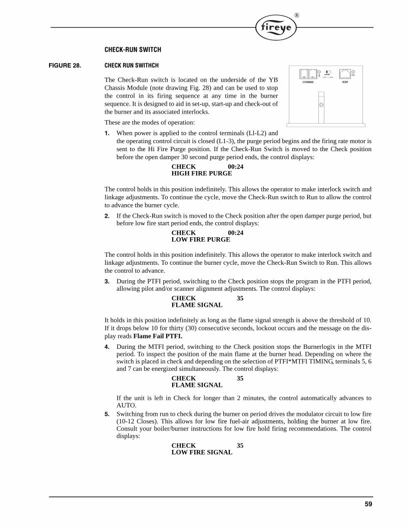
59
®
CHECK-RUN SWITCH
FIGURE 28. CHECK RUN SWITHCH
The Check-Run switch is located on the underside of the YBChassis Module (note drawing Fig. 28) and can be used to stopthe control in its firing sequence at any time in the burnersequence. It is designed to aid in set-up, start-up and check-out ofthe burner and its associated interlocks.
These are the modes of operation:
1. When power is applied to the control terminals (Ll-L2) andthe operating control circuit is closed (L1-3), the purge period begins and the firing rate motor issent to the Hi Fire Purge position. If the Check-Run Switch is moved to the Check positionbefore the open damper 30 second purge period ends, the control displays:
The control holds in this position indefinitely. This allows the operator to make interlock switch andlinkage adjustments. To continue the cycle, move the Check-Run switch to Run to allow the controlto advance the burner cycle.
2. If the Check-Run switch is moved to the Check position after the open damper purge period, butbefore low fire start period ends, the control displays:
The control holds in this position indefinitely. This allows the operator to make interlock switch andlinkage adjustments. To continue the burner cycle, move the Check-Run Switch to Run. This allowsthe control to advance.
3. During the PTFI period, switching to the Check position stops the program in the PTFI period,allowing pilot and/or scanner alignment adjustments. The control displays:
It holds in this position indefinitely as long as the flame signal strength is above the threshold of 10.If it drops below 10 for thirty (30) consecutive seconds, lockout occurs and the message on the dis-play reads Flame Fail PTFI.
4. During the MTFI period, switching to the Check position stops the Burnerlogix in the MTFIperiod. To inspect the position of the main flame at the burner head. Depending on where theswitch is placed in check and depending on the selection of PTFI*MTFI TIMING, terminals 5, 6and 7 can be energized simultaneously. The control displays:
If the unit is left in Check for longer than 2 minutes, the control automatically advances toAUTO.
5. Switching from run to check during the burner on period drives the modulator circuit to low fire(10-12 Closes). This allows for low fire fuel-air adjustments, holding the burner at low fire.Consult your boiler/burner instructions for low fire hold firing recommendations. The controldisplays:
���������������� ��������
�� ����� ���
CHECK 00:24HIGH FIRE PURGE
CHECK 00:24LOW FIRE PURGE
CHECK 35FLAME SIGNAL
CHECK 35FLAME SIGNAL
CHECK 35LOW FIRE SIGNAL
60
OPERATIONAL TEST (BURNER COMMISSIONING)
Close the manual main shut-off fuel valve.
1. Recheck all limit circuit wiring for proper operation and correct connection.
2. Confirm that the automatic main fuel valves are wired to terminal “7.” 3. Power the control and electronically check the proper sequence of operation according to the
System Operation section on page 36 of this bulletin.4. After assuring yourself that all interlocks and valves are properly wired and that the sequence of
operation is correct, open the manual main shut-off fuel valve and proceed cautiously throughthe boiler light off process. Check all safety interlocks for proper shut down of the boiler.
When the installation and all burner adjustments are completed, the entire burner control system istested in accordance with the burner manufacturer’s instructions. The procedure should verify thecorrect operation of:
1. Each operating control (temperature, pressure, etc.).
2. Each limit switch (temperature, pressure, low water cutoff, etc.).3. Each interlock switch (airflow switch, high and low fuel pressure or temperature switches, purge
and low fire start switches, fuel valve proof of closure interlock, etc.).4. Pilot flame failure response and lockout. 5. Main flame failure response and lockout. 6. Tight shut off of all fuel valves.
Line Voltage Test
A Voltage Check is necessary to identify a potential problem with the supply to the control. Thiscould be caused by an improperly sized or faulty transformer, faulty load coils or low entry voltage.Follow this procedure:
1. Monitor the L1-L2 mains supply throughout a complete burner cycle. The acceptable voltagerange is 102V-132V (211VAC to 253VAC). At no time during the cycle can the voltage dipbelow the minimum level.
2. Check other load terminals (M/L2, 5/L2, 6/L2, 7/L2) for voltage occurring at improper times orimproper values.
TEST CHECKOUT PROCEDURES
Normal Pilot Flame Test
1. At the start of PTFI, place the RUN/CHK switch in the CHK position.
2. Observe the pilot flame signal on the display or meter. If the average signal is below the mini-mum of 10, readjust the pilot flame or realign the flame detector.
3. During the pilot flame test, if flame is not detected for a continuous 30 seconds, the control locksout. To re-establish the pilot flame trial for ignition (PTFI), manual reset of the lockout switch isrequired, and a complete prepurge must be done.
WARNING: Before testing the Burnerlogix operation on the boiler, close the manual mainshut-off fuel valve. Failure to do this may cause injury or property damage.
CAUTION: Live voltage is necessary to perform this test.
CAUTION: Before making a pilot flame test, manually shut off the fuel supply to the mainburner so only the PILOT valve is operating.

61
®
4. When UV flame detection is used, a test is required to verify that UV radiation from the ignitionspark is not being detected. To accomplish this, manually shut off both pilot and main fuels. Ini-tiate a normal start-up, and when the PTFI display comes on, observe the display which shouldread no signal more than 4. If more than 4 is observed, realign the UV scanner, and/or shield thespark from the scanner’s view.
5. With all methods of flame detection, check pilot flame failure response by manually shutting offthe pilot fuel and then initiate a normal start-up. With no pilot flame present, the control will de-energize the pilot assembly at the end of the trial for ignition interval, and the control will lock-out. Also check to verify that the ignition spark does not cause an electrical interference oninfrared or flame rod applications.
Main Flame Test
Note: This test requires an interrupted pilot (a pilot that shuts off after main flame has been estab-lished).1. Proceed through a normal startup. After the pilot flame is shut off, observe the reading on the
display. If the signal reading is low, readjust main flame or realign detector.
2. Check main flame failure protection by manually shutting off the main fuel supply. Within 4seconds after main flame goes out, the fuel valve will be de-energized. The alarm circuit will beenergized following safety lockout.
Minimum Pilot Test (Pilot turn down test)
This test assures that the flame detector will not detect a pilot flame too small to reliably light off themain flame. The test should be made on every new installation and following any repositioning orreplacement of the flame detector. This procedure should not be used on a direct spark ignited burner.
1. Turn off the main fuel supply manually.
2. At the start of PTFI, place the Check-run switch in the check position.3. Reduce the pilot fuel supply until the display reads below 10.4. Slowly increase the fuel to the pilot until the display reads 10. This is minimum pilot flame that
the flame detector will reliably detect.5. Place the Check-run switch in the Run position. When the main fuel safety shut-off valve is
energized, slowly open the manual main fuel valve. 6. Observe the light-off of the main flame. It must be smooth and normal.
7. Repeat this test until a reliable and smooth light-off occurs with the minimum pilot.8. After this test is completed, increase the fuel to the pilot to its normal setting.
CAUTION: The minimum pilot test must be accomplished by a trained and qualifiedburner technician
CAUTION: If the main flame does not ignite immediately, shut off the main fuel. Realignthe detector to require larger minimum pilot flame

62
FIGURE 29. PILOT FLAME TEST
Scanner Wiring
Take care to see that ignitor cables and scanner cables are routed away from one another on all instal-lations. These cables, when crossed or run together, may interfere with the proper operation of theBurnerlogix control.
If you are experiencing erratic operation or inappropriate characters on the display during the trial forignition period, the cause is likely to be ignitor noise. Check for worn ignitor cable insulation, brokenor cut insulation or loose connectors at the electrode and transformers
BURNERLOGIX GROUNDING RULES
The BurnerLogix system, is microprocessor based and requires a ground system that provides a zero-voltage reference. The voltage measured from L2 to all other terminals except L1 should be 0 volts.
1. The most effective ground is to run the ground wire in the same raceway as the hot and neutralfrom the main distribution service panel (not intermediate sub-panels) to the burner controlpanel and insure that this ground wire is well bonded to the control panel.
2. The wiring base of the BurnerLogix must have earth ground providing a connection between thesub-base and the control panel or the burner.
3. The earth ground wire must be capable of conducting the current to blow the 20A fuse in eventof an internal short circuit. A number 14 AWG copper conductor is adequate, wide straps orbrackets are preferred rather than lead wires.
4. The ground path needs to be low impedance (less than 1 ohm) to the equipment frame which inturn needs a low impedance to earth ground. For a ground path to be low impedance at RF fre-quencies, the connection must be made with minimum length conductors having maximum sur-face areas.
5. All connections should be free of nonconductive coatings and protected against rust. 6. Utilizing conduit as a means of providing a ground must be avoided. 7. Installing ground rods at the burner control panel defeats the purpose of a single point ground as
described above and could also present a safety hazard.
INSTALLATION
Do not run high voltage ignition transformer wires in the same conduit with flame detection wiring.Do not run scanner wires in a conduit with line voltage circuits. Ensure the frame of the ignitiontransformer is securely connected to control panel frame or preferably the burner frame.
The BurnerLogix chassis (YB110/YB230) contains a transient suppressing device connected inter-nally across hot and neutral and to earth ground, terminal E. For this to be effective terminal E or thegreen wire in the pig-tail wiring base must be grounded well.
MAINFLAME
REFRACTORY
MAINBURNER
PILOTFLAME
SCANNER
PILOTBURNER
INSUFFICIENT PILOT
MAINFLAME
MAINBURNER
PILOTFLAME
SCANNER
PILOTBURNER
MINIMUM PILOT
MAINFLAME
MAINBURNER
PILOTFLAME
SCANNER
PILOTBURNER
NORMAL PILOT
REFRACTORYREFRACTORY

63
®
REMOTE DISPLAY
To locate the display remotely from the BurnerLogix control, mounting kits are available. These areFireye part numbers 129-178-4 or 129-178-8. Each kit contains a gasket, hardware to mount the dis-play and a 4 or 8 foot cable.
Care must be taken not to route the ED580 cable in close proximity to any starter motor contactorslocated in the control panel or across any high voltage ignition wires. Refer to Fireye bulletin E-8002for proper installation.
COMMUNICATIONS
When interfacing Fireye controls to a communication system, be it a PLC or other microprocessorbased device, ferrite cores should also be utilized. Proper twisted shielded pair cable must be uti-lized. In a multi-drop system, the shields should be tied together within a cabinet and not to anyground point. The shield at the source end of the cable of the multi-drop connection can then be ter-minated to ground. Source end is defined as the originating end of the communication system
Care must be taken not to route communication cables in close proximity to any starter motor con-tactors located in the control panel or across any high voltage ignition wires. Refer to Fireye bulletin E-8002 for proper installation.
SCANNERS
The armored cable supplied with the Ultra-Violet and Infrared scanners should be connected toequipment by means of a good mechanical connection such as a conduit fitting. It may be necessaryto utilize heat insulator (P/N 35-69) to isolate the sensing end of the scanner from boiler ground.Care must be taken not to route the scanner cable across the high voltage ignition cable. The highenergy ignition cable should be checked periodically for cracking, connections and aging.
In applications using flame rod units, it may be beneficial to route a separate return wire from the S2terminal to the flame rod assembly. This will minimize the effects of transient currents flowing intothe BurnerLogix.
In all cases, scanner wires should be routed in separate conduit and not joined with any high voltageAC or ignition cables.
MAINTENANCE
Periodically, the spark electrode should be inspected for proper gapping and cracked ceramics. Atignition time, the high energy from the ignition transformer will attempt to conduct to the point ofleast resistance and with an improper spark gap, where the conduction takes place will no longer becontrolled.
The VA rating of the control transformer must be sized to handle the inrush currents of the pilot sole-noid and ignition transformer at PTFI and then the inrush currents of the main fuel valve assembly atMTFI time.
Inspect neatness of wiring in junction boxes and cabinets. It is best to have connections short anddirect and also not having wires bunched up and tied off. Also, connections should be periodicallyinspected for tightness and corrosion
Type 48PT2 Infrared and Type UV1A, UV2, 45UV5 Ultra-violet Scanners
The viewing area of the scanner must be kept clean. Even a small amount of contamination willreduce the flame signal reaching the detector by a measurable amount. Wipe the viewing area rou-tinely using a soft cloth dampened with concentrated detergent.
— Type 48PT2 Scanners include a replaceable #4-263-1 Firetron cell.
— Type 45UV5 Scanners include a replaceable #4-314-1 UV tube.
Type 69ND1 Flame Rod
The flame rod and its insulator should be kept clean by washing routinely with soap and water. Rodsshould be routinely replaced as they oxidize.

64
Flame Signal Strength
Routine observation of the flame signal strength will forewarn any deterioration in the capability ofthe flame detector or its application.
Contacts
There are no accessible contacts in the BurnerLogix. Where contacts are used, their design assureslong trouble-free life when the load circuits are maintained within the published load ratings.
Humidity
In areas of high humidity, the control chassis should be removed and placed in a dry atmospherewhen the system is expected to be out of service for an extended period.
Periodic Safety Check
It is recommended that a procedure be established to test the complete flame safeguard system atleast once a month,. This test should verify the proper operation of all limit switches and safety inter-locks as well as flame failure protection and fuel safety shutoff valve tightness.
Rotation
It is recommended that control and scanner units purchased as spares be installed periodically toensure proper operation.
NOTICEWhen Fireye products are combined with equipment manufactured by others and/or integrated intosystems designed or manufactured by others, the Fireye warranty, as stated in its General Terms andConditions of Sale, pertains only to the Fireye products and not to any other equipment or to thecombined system or its overall performance.
WARRANTIESFIREYE guarantees for one year from the date of installation or 18 months from date of manufactureof its products to replace, or, at its option, to repair any product or part thereof (except lamps andphotocells) which is found defective in material or workmanship or which otherwise fails to conformto the description of the product on the face of its sales order. THE FOREGOING IS IN LIEU OFALL OTHER WARRANTIES AND FIREYE MAKES NO WARRANTY OF MERCHANT-ABILITY OR ANY OTHER WARRANTY, EXPRESS OR IMPLIED. Except as specificallystated in these general terms and conditions of sale, remedies with respect to any product or partnumber manufactured or sold by Fireye shall be limited exclusively to the right to replacement orrepair as above provided. In no event shall Fireye be liable for consequential or special damages ofany nature that may arise in connection with such product or part.
FIREYE BL-10013 Manchester Road SEPTEMBER 23, 2015Derry, New Hampshire 03038 USA Supersedes July 15, 2015www.fireye.com