YASKAWA AC Drive-V1000 Option MECHATROLINK-III Technical ...
51
MECHATROLINK-III YASKAWA AC Drive-V1000 Option Technical Manual MANUAL NO. SIEP C730600 63B To properly use the product, read this manual thoroughly and retain for easy reference, inspection, and maintenance. Ensure the end user receives this manual. Type: SI-ET3/V
Transcript of YASKAWA AC Drive-V1000 Option MECHATROLINK-III Technical ...

MECHATROLINK-IIIYASKAWA AC Drive-V1000 Option
Technical Manual
MANUAL NO. SIEP C730600 63B
To properly use the product, read this manual thoroughly and retain for easy reference, inspection, and maintenance. Ensure the end user receives this manual.
Type: SI-ET3/V

2 YASKAWA ELECTRIC SIEP C730600 63B V1000 Option SI-ET3/V Technical Manual
Copyright © 2013 YASKAWA ELECTRIC CORPORATIONAll rights reserved. No part of this publication may be reproduced, stored in a retrieval system, or transmitted, in any form or by any means, mechanical, electronic, photocopying, recording, or otherwise, without the prior written permission of Yaskawa. No patent liability is assumed with respect to the use of the information contained herein. Moreover, because Yaskawa is constantly striving to improve its high-quality products, the information contained in this manual is subject to change without notice. Every precaution has been taken in the preparation of this manual. Yaskawa assumes no responsibility for errors or omissions. Neither is any liability assumed for damages resulting from the use of the information contained in this publication.

YASKAWA ELECTRIC SIEP C730600 63B V1000 Option SI-ET3/V Technical Manual 3
Table of Contents
1 PREFACE AND SAFETY . . . . . . . . . . . . . . . . . . . . . . . . . . . . . . . . . . . . . . . . . . . . . . . 42 PRODUCT OVERVIEW . . . . . . . . . . . . . . . . . . . . . . . . . . . . . . . . . . . . . . . . . . . . . . . . 73 RECEIVING . . . . . . . . . . . . . . . . . . . . . . . . . . . . . . . . . . . . . . . . . . . . . . . . . . . . . . . . . 84 OPTION COMPONENTS . . . . . . . . . . . . . . . . . . . . . . . . . . . . . . . . . . . . . . . . . . . . . . . 95 INSTALLATION PROCEDURE . . . . . . . . . . . . . . . . . . . . . . . . . . . . . . . . . . . . . . . . . 116 RELATED DRIVE PARAMETERS . . . . . . . . . . . . . . . . . . . . . . . . . . . . . . . . . . . . . . . 207 TRANSMISSION INTERFACE . . . . . . . . . . . . . . . . . . . . . . . . . . . . . . . . . . . . . . . . . . 228 MECHATROLINK-III COMMANDS . . . . . . . . . . . . . . . . . . . . . . . . . . . . . . . . . . . . . . 279 MAIN COMMAND. . . . . . . . . . . . . . . . . . . . . . . . . . . . . . . . . . . . . . . . . . . . . . . . . . . . 2910 SUB-COMMANDS . . . . . . . . . . . . . . . . . . . . . . . . . . . . . . . . . . . . . . . . . . . . . . . . . . . 4211 TROUBLESHOOTING . . . . . . . . . . . . . . . . . . . . . . . . . . . . . . . . . . . . . . . . . . . . . . . . 4712 SPECIFICATIONS . . . . . . . . . . . . . . . . . . . . . . . . . . . . . . . . . . . . . . . . . . . . . . . . . . . 49

4 YASKAWA ELECTRIC SIEP C730600 63B V1000 Option SI-ET3/V Technical Manual
1 Preface and Safety
1 Preface and SafetyYaskawa manufactures products used as components in a wide variety of industrial systems and equipment. The selection and application of Yaskawa products remain the responsibility of the equipment manufacturer or end user. Yaskawa accepts no responsibility for the way its products are incorporated into the final system design. Under no circumstances should any Yaskawa product be incorporated into any product or design as the exclusive or sole safety control. Without exception, all controls should be designed to detect faults dynamically and fail safely under all circumstances. All systems or equipment designed to incorporate a product manufactured by Yaskawa must be supplied to the end user with appropriate warnings and instructions as to the safe use and operation of that part. Any warnings provided by Yaskawa must be promptly provided to the end user. Yaskawa offers an express warranty only as to the quality of its products in conforming to standards and specifications published in the Yaskawa manual. NO OTHER WARRANTY, EXPRESS OR IMPLIED, IS OFFERED. Yaskawa assumes no liability for any personal injury, property damage, losses, or claims arising from misapplication of its products.
Applicable DocumentationThe following manuals are available for the SI-ET3/V option:
Terms
Registered Trademarks• MECHATROLINK-III is a trademark of the MECHATROLINK Members Association (MMA).• All trademarks are the property of their respective owners.
Option UnitYASKAWA AC Drive -V1000 OptionSI-ET3/V MECHATROLINK-IIIInstallation ManualManual No: TOBP C730600 63
Read this manual first.The installation manual is packaged with the option and contains a basic overview of wiring, settings, functions, and fault diagnoses.
YASKAWA AC Drive -V1000 OptionSI-ET3/V MECHATROLINK-IIITechnical ManualManual No: SIEP C730600 63(This book)
The technical manual contains detailed information.Access the following sites to obtain the technical manual:U.S.: http://www.yaskawa.comEurope: http://www.yaskawa.eu.comJapan: http://www.e-mechatronics.comOther areas: contact a Yaskawa representative.
Drive
YASKAWA AC Drive-V1000 Quick Start Guide
Access the following sites to obtain instruction manuals for Yaskawa products:U.S.: http://www.yaskawa.comEurope: http://www.yaskawa.eu.comJapan: http://www.e-mechatronics.comOther areas: contact a Yaskawa representative.For questions, contact the local Yaskawa sales office or the nearest Yaskawa representative.
YASKAWA AC Drive-V1000 Technical Manual
Note: Indicates supplemental information that is not related to safety messages.Drive: YASKAWA AC Drive V1000MECHATROLINK-III option: YASKAWA AC Drive -V1000 Option SI-ET3/V MECHATROLINK-III
STOP

1 Preface and Safety
YASKAWA ELECTRIC SIEP C730600 63B V1000 Option SI-ET3/V Technical Manual 5
Supplemental Safety InformationRead and understand this manual before installing, operating, or servicing this option. The option must be installed according to this manual and local codes.
The following conventions are used to indicate safety messages in this manual. Failure to heed these messages could result in serious or possibly even fatal injury or damage to the products or to related equipment and systems.
General Safety
DANGER Indicates a hazardous situation, which, if not avoided, will result in death or serious injury.
W ARNING Indicates a hazardous situation, which, if not avoided, could result in death or serious injury.
CAUTION Indicates a hazardous situation, which, if not avoided, could result in minor or moderate injury.
NOTICE
Indicates an equipment damage message.
General Precautions• The diagrams in this section may include options and drives without covers or safety shields to illustrate details. Be
sure to reinstall covers or shields before operating any devices. The option should be used according to the instructions described in this manual.
• Any illustrations, photographs, or examples used in this manual are provided as examples only and may not apply to all products to which this manual is applicable.
• The products and specifications described in this manual or the content and presentation of the manual may be changed without notice to improve the product and/or the manual.
• When ordering new copies of the manual, contact a Yaskawa representative or the nearest Yaskawa sales office and provide the manual number shown on the front cover.
DANGER Heed the safety messages in this manual.Failure to comply will result in death or serious injury.The operator is responsible for injuries or equipment damage caused from failure to heed the warnings in the manual.
NOTICE
Do not modify the drive or option circuitry.Failure to comply could result in damage to the drive or option and will void warranty. Yaskawa is not responsible for any modification of the product made by the user. This product must not be modified.Do not expose the drive or the option to halogen group disinfectants.Failure to comply may cause damage to the electrical components in the option. Do not pack the drive in wooden materials that have been fumigated or sterilized.Do not sterilize the entire package after the product is packed.

1 Preface and Safety
6 YASKAWA ELECTRIC SIEP C730600 63B V1000 Option SI-ET3/V Technical Manual
Option Unit Warning LabelsWarning information is displayed on the option unit as shown in the figure below. Follow all warnings and safety instructions when using the product.
When using the drive in an area that may require displaying warning information in Japanese or Chinese, a warning label is provided with the option. This label can be placed over the English and French warnings on the front of the option.
Warning Contents
V1000
Warning information
AVERTISSEMENTLire le manuel avant l'installation.Attendre 5 minutes apres la coupure de l'alimentation,pour permettre la decharge des condensateurs.Pour repondre aux exigences , s assurer que leneutre soit relie a la terre, pour la serie 400V.
WARNINGRead manual before installing.Wait 5 minutes for capacitor discharge afterdisconnecting power supply.To conform to requirements, make sureto ground the supply neutral for 400V class.
Risk of electric shock.
Risque de dechargeelectrique.
V1000

2 Product Overview
YASKAWA ELECTRIC SIEP C730600 63B V1000 Option SI-ET3/V Technical Manual 7
2 Product Overview
About This ProductThe MECHATROLINK-III option provides a communications connection between the drive and a MECHATROLINK-III network. The option connects the drive to a MECHATROLINK-III network and facilitates the exchange of data.
This manual explains the handling, installation and specifications of this product.
MECHATROLINK-III is a communications link to connect industrial devices (such as smart motor controllers, operator interfaces, and variable frequency drives) as well as control devices (such as programmable controllers and computers) to a network. MECHATROLINK-III is a simple, networking solution that reduces the cost and time to wire and install factory automation devices, while providing interchangeability of like components from multiple vendors.
By installing the MECHATROLINK-III option to a drive, it is possible to do the following from a MECHATROLINK-III master device:
• operate the drive• monitor the operation status of the drive• change parameter settings
Applicable ModelsThe option can be used with the drive models in Table 1.
Table 1 Applicable Models
Drive Series Drive Model Number Software Version <1>
<1> See “PRG” on the drive nameplate for the software version number.
V1000 CIMR-V A ≥1023

8 YASKAWA ELECTRIC SIEP C730600 63B V1000 Option SI-ET3/V Technical Manual
3 Receiving
3 ReceivingPlease perform the following tasks upon receipt of the option:
• Inspect the option for damage. Contact the shipper immediately if the option appears damaged upon receipt.• Verify receipt of the correct model by checking the model number printed on the name plate of the option package. • Contact your supplier if you have received the wrong model or the option does not function properly.
Contents and PackagingTable 2 Option Package Contents
Tools Required for InstallationA Phillips screwdriver (M3, M3.5 to M6 metric or #1, #2 U.S. standard <1>) is required to install the option.
Description: Option Unit Ground Wire Warning Labels Installation Manual
_
Quantity: 1 4 1 1
<1> Screw sizes vary by drive capacity. Select a screwdriver that matches the drive capacity.
MANUAL

4 Option Components
YASKAWA ELECTRIC SIEP C730600 63B V1000 Option SI-ET3/V Technical Manual 9
4 Option Components
SI-ET3/V OptionFigure 1
Figure 1 Option Unit
DimensionsThe installed option adds 27 mm (1.06 in.) to the total depth of the drive.Figure 2
Figure 2 Dimensions
A – LED (LK1) <1>
<1> Refer to Option LED Display on page 10 for details on the LEDs.<2> The ground wire provided in the option shipping package must be connected during installation.
I – Functional earth cable connection (FE)B – LED (LK2) <1> J – Mounting tabsC – Option cover K – Ground wire <2>
D – LED (CON) <1> L – Pass-through hole for wireE – LED (R/E) <1> M – Communication connector CN2F – PCB N – Communication connector CN1G – Screw hole (attaching option cover) O – Option connectorH – Nameplate
V1000E
D
C
A
B
J
G
F
J
I
K
L
N M
O
H
0000
0000
0000
001X
XX
R/ECON
LK1LK2
Option with cover removedUndersideOption with cover attached
27 mm (1.06 in.) V1000

4 Option Components
10 YASKAWA ELECTRIC SIEP C730600 63B V1000 Option SI-ET3/V Technical Manual
ConnectorTable 3 Connector Descriptions
Figure 3
Figure 3 MECHATROLINK-III Option Connector
Option LED DisplayThe MECHATROLINK-III Option has four LEDs that indicate the option card or communication status.
Checking LED OperationTable 4 Option LED States
Connector Pin No. Signal Name I/O Function
CN1/CN2
1 TXD_P I/O Send data (+): OUT2 TXD_N I/O Send data (-): OUT3 RXD_P I/O Receive data (+): IN4 (NC) – –5 (NC) – –6 RXD_N I/O Receive data (-): N7 (NC) – –8 (NC) – –
Shell SLD – Shield
Name Display Operating Status Remarks
R/E
Lit in green Power supply on • SI-ET3/V has been successfully powered up
• An internal, self-diagnostic check completed in the SI-ET3/V
Lit in red Error • Error/alarm occured• Command error occurred (parameter error, phase error, combination error)
Flashing in red SI-ET3 error Error found during SI-ET3/V’s self-diagnostic check
Unlit Power supply off• The drive has no power• SI-ET3/V is not properly connected to the drive, or SI-ET3/V has no power• An internal, self-diagnostic error occurred in the SI-ET3/V
CONLit in green Connection established Established connection
Unlit Connection unestablished Connection with master device is not established
LK1
Lit in green Connector CN1 connected Connector CN1 is connected to other stations
Unlit Connector CN1 disconnected
Connector CN1 is not connected to other stations (cable not connected, cable disconnected, other stations not powered up)
LK2
Lit in green Connector CN2 connected Connector CN2 is connected to other stations
Unlit Connector CN2 disconnected
Connector CN2 is not connected to other stations (cable not connected, cable disconnected, other stations not powered up)
2 4 6 81 3 5 7
CN2CN1V1000

5 Installation Procedure
YASKAWA ELECTRIC SIEP C730600 63B V1000 Option SI-ET3/V Technical Manual 11
5 Installation Procedure
Section Safety
DANGER
Electrical Shock HazardDo not connect or disconnect wiring while the power is on.Failure to comply will result in death or serious injury.Disconnect all power to the drive, wait at least five minutes after all indicators are off, measure the DC bus voltage to confirm safe level, and check for unsafe voltages before servicing to prevent electric shock. The internal capacitor remains charged even after the power supply is turned off. The charge indicator LED will extinguish when the DC bus voltage is below 50 Vdc.
W ARNING
Electrical Shock HazardDo not remove option board cover while the power is on.Failure to comply could result in death or serious injury.The diagrams in this section may include option units and drives without covers or safety shields to show details. Be sure to reinstall covers or shields before operating any devices. The option should be used according to the instructions described in this manual.
Do not allow unqualified personnel to use equipment.Failure to comply could result in death or serious injury.Maintenance, inspection, and replacement of parts must be performed only by authorized personnel familiar with installation, adjustment, and maintenance of this product.
Do not use damaged wires, place excessive stress on wiring, or damage the wire insulation.Failure to comply could result in death or serious injury.
Fire HazardTighten all terminal screws to the specified tightening torque.Loose electrical connections could result in death or serious injury by fire due to overheating of electrical connections.
NOTICE
Damage to EquipmentObserve proper electrostatic discharge (ESD) procedures when handling the option, drive, and circuit boards.Failure to comply may result in ESD damage to circuitry.
Never shut the power off while the drive is outputting voltage.Failure to comply may cause the application to operate incorrectly or damage the drive.
Do not operate damaged equipment. Failure to comply may cause further damage to the equipment.Do not connect or operate any equipment with visible damage or missing parts.
Do not use unshielded cable for control wiring.Failure to comply may cause electrical interference resulting in poor system performance.Use shielded twisted-pair wires and ground the shield to the ground terminal of the drive.

5 Installation Procedure
12 YASKAWA ELECTRIC SIEP C730600 63B V1000 Option SI-ET3/V Technical Manual
Prior to Installing the OptionPrior to installing the option, wire the drive, make necessary connections to the drive terminals, and verify that the drive functions normally without the option installed. Refer to the instruction manmual packaged with the drive for information on wiring and connecting the drive.
Installing the OptionRefer to the instructions below to install the option.
DANGER! Electrical Shock Hazard. Do not connect or disconnect wiring while the power is on. Failure to comply could result in death or serious injury. Before installing the option, disconnect all power to the drive. The internal capacitor remains charged even after the power supply is turned off. The charge indicator LED will extinguish when the DC bus voltage is below 50 Vdc. To prevent electric shock, wait at least five minutes after all indicators are off and measure the DC bus voltage level to confirm safe level.
1. Shut off power to the drive, wait at least five minutes after confirming the DC bus voltage is safe, then loosen the screw that fastens the front cover in place and remove the front cover. This drive front cover will be replaced by the option cover. Cover removal varies depending on drive size.
NOTICE: Damage to Equipment. Observe proper electrostatic discharge procedures (ESD) when handling the option, drive, and circuit boards. Failure to comply may result in ESD damage to circuitry.Figure 4
Figure 4 Remove Front Cover
Properly connect all pins and connectors. Failure to comply may prevent proper operation and possibly damage equipment.
Check wiring to ensure that all connections are correct after installing the option and connecting any other devices. Failure to comply may result in damage to the option.
NOTICE
V1000

5 Installation Procedure
YASKAWA ELECTRIC SIEP C730600 63B V1000 Option SI-ET3/V Technical Manual 13
2. The remaining installation steps differ based on drive model. Find the drive model number on the drive nameplate and refer to the step indicated in Table 5 based on your model number.
Table 5 Installation Steps Based on Drive Model
3. For IP20/Open-Chassis models CIMR-V A B, remove the bottom cover of the drive by applying pressure to the tabs on each side of the bottom cover. Pull the bottom cover away from the drive while pushing in on the tabs to release the cover from the drive. Refer to Figure 5 for details.Refer to Figure 6 for drive models CIMR-V BA0006B to BA0018B, 2A0008B to 2A0069B, and 4A0001B to 4A0038B, which require removing the terminal cover prior to removing the bottom cover.
Figure 5
Figure 5 Remove the Bottom Cover on an IP20/Open-Chassis Drive(Models CIMR-V BA0001B to BA0003B and 2A0001B to 2A0006B)
Figure 6
Figure 6 Remove the Terminal Cover and Bottom Cover on an IP20/Open-Chassis Drive(Models CIMR-V BA0006B to BA0018B; 2A0008B to 2A0069B; 4A0001B to 4A0038B)
4. On IP20/Open-Chassis models, connect the drive side of the ground wire to the drive ground terminal.Note: The four different ground wires packaged with the option connect the option to different drive models. Select the proper ground
wire depending on drive size. Refer to Table 6 for ground wire selection by drive model.Figure 7
Figure 7 Connect the Ground Wire on an IP20/Open-Chassis Drive
Enclosure Type
<1> Installing the option on an IP20/NEMA Type 1 enclosure drive voids NEMA Type 1 protection while maintaining IP20 conformity.
Drive Model Proceed to Step PageIP20/Open-Chassis CIMR-V A B 3. 13
IP20/NEMA Type 1 <1> CIMR-V A F 6. 14
V1000
Bottom CoverTerminal Cover
V1000
Ground terminal
Ground wire
Ground wire
Drive-side connectorScrew size:M3.5 to M6
Option unit connectorScrew size: M3
V1000

5 Installation Procedure
14 YASKAWA ELECTRIC SIEP C730600 63B V1000 Option SI-ET3/V Technical Manual
Table 6 Ground Wire Selection
5. For IP20/Open-Chassis models, go to Step 9. on page 15.6. For IP20/NEMA Type 1 enclosure models CIMR-V A F, loosen the screw on the front of the NEMA
Type 1 terminal cover and remove it from the drive. Refer to Figure 8 for details.Refer to Figure 9 for drive models CIMR-V BA0006F to BA0018F, 2A0010F to 2A0069F, and 4A0001F to 4A0038F, which require removing the plastic terminal cover prior to removing the NEMA Type 1 terminal cover.
Note: Installing the option on an IP20/NEMA Type 1 enclosure drive voids NEMA Type 1 protection while maintaining IP20 conformity.
Figure 8
Figure 8 Remove the NEMA Type 1 Terminal Cover (CIMR-V BA0001F to BA0003F, 2A0001F to 2A0006F)Figure 9
Figure 9 Remove the Terminal Cover on an IP20/NEMA Type 1 Drive(Models CIMR-V BA0006F to BA0018F; 2A0008F to 2A0069F; 4A0001F to 4A0038F)
Ground Wire Length (mm/in)
Drive ModelCIMR-V
Single-Phase 200 V Class
Three-Phase 200 V Class
Three-Phase 400 V Class
150/5.9BA0001BA0002BA0003
2A00012A00022A00042A0006
–
200/7.9
BA0006BA0010BA0012BA0018
2A00102A00122A0020
4A00014A00024A00044A00054A00074A00094A0011
250/9.8 – 2A00302A0040
4A00184A0023
400/15.7 – 2A00562A0069
4A00314A0038
V1000
V1000

5 Installation Procedure
YASKAWA ELECTRIC SIEP C730600 63B V1000 Option SI-ET3/V Technical Manual 15
7. For models CIMR-V BA0001F to BA0003F, 2A0001F to 2A0006F, loosen the screws attaching the NEMA Type 1 conduit bracket to the drive to remove the NEMA Type 1 conduit bracket.
Figure 10
Figure 10 Remove the NEMA Type 1 Conduit Bracket
8. On NEMA Type 1 enclosure models (CIMR-V BA0001F to BA0003F, 2A0001F to 2A0006F), the screw for the drive ground terminal also acts as one of the screws that attaches the NEMA Type 1 conduit bracket to the drive. Reattach the NEMA Type 1 conduit bracket according to Figure 11 and connect the drive-side of the ground wire to the drive ground terminal.
Note: The four different ground wires packaged with the option connect the option to different drive models. Select the proper ground wire depending on drive size. Refer to Table 6 on page 14 for ground wire selection by drive model.
Figure 11
Figure 11 Reattach the NEMA Type 1 Conduit Bracket and Connect the Ground Wire for models CIMR-V BA0001F to BA0003F, 2A0001F to 2A0006F
9. Reattach the bottom cover. Keep the ground wire inside of the bottom cover when reattaching.Figure 12
Figure 12 Reattach the Bottom Cover
V1000
Ground terminal
Ground wire
Drive ground terminal/NEMA Type 1 conduit bracket screw
Ground wire
Drive-side connectorScrew size:M3.5 to M6
Option unit connectorScrew size: M3
V1000
IP20/Open-Chassis IP20/NEMA Type 1 Enclosure
V1000

5 Installation Procedure
16 YASKAWA ELECTRIC SIEP C730600 63B V1000 Option SI-ET3/V Technical Manual
10. On models CIMR-V BA0006 to BA0018 , 2A0008 to 2A0069 , and 4A0001 to 4A0038 , reattach the terminal cover.Refer to Figure 13 and Figure 14 for drive models CIMR-V BA0006 to BA0018 , 2A0008 to 2A0020 , and 4A0001 to 4A0011 , which require routing the ground wire through the provided notch when reinstalling the terminal cover.
Figure 13
Figure 13 Reattach the Terminal Cover(Models CIMR-V BA0006 to BA0018 ; 2A0008 to 2A0069 ; 4A0001 to 4A0038 )
Figure 14
Figure 14 Terminal Cover Ground Wire Notch(Models CIMR-V BA0006 to BA0018 ; 2A0008 to 2A0020 ; 4A0001 to 4A0011 )
11. Remove the option cover and pass the ground wire through the inside of the drive bottom cover and into the through-hole for the ground wire at the front of the option.
Figure 15
Figure 15 Ground Wire Routing
V1000
Ground wirerouting notch
V1000
Option Cover
V1000

5 Installation Procedure
YASKAWA ELECTRIC SIEP C730600 63B V1000 Option SI-ET3/V Technical Manual 17
12. Attach the option to the drive. Properly seat the tabs on the left and right sides of the option to the drive case.Figure 16
Figure 16 Connect the Option
13. Connect the ground wire at the option ground terminal. Tighten the screw to 0.5 to 0.6 N m or (4.4 to 5.3 in lbs) using an M3 Phillips screwdriver.
Figure 17
Figure 17 Connect the Ground Wire to the Option
14. Connect the MECHATROLINK-III communication cable to option communication connector CN1 or CN2. Refer to Communication Cable Wiring on page 18 for details.
Note: Do not connect or disconnect the communication cable while the drive is powered up or while the drive is in operation. Failure to comply may cause a static discharge, which will cause the option card to stop working properly. Cycle power on the drive and option card to reestablish functionality.
Figure 18
Figure 18 Communication Cable Ports
Line up tabs
Line up tabs
V1000
Option ground terminal
V1000
V1000

5 Installation Procedure
18 YASKAWA ELECTRIC SIEP C730600 63B V1000 Option SI-ET3/V Technical Manual
MECHATROLINK-III Communication Cable SpecificationWire the MECHATROLINK-III communications cables to the communications connector (CN1 or CN2). Install MECHATROLINK-III communications cables apart from main-circuit wiring and other electrical and power lines.
Note: Maximum transmission distance is 100 m (3937.0 in.). Minimum wiring distance between stations is 0.2 m (7.9 in.)
Connection Diagram
Figure 19 Wiring Diagram
Communication Cable WiringThe dual communication cable ports on the option board act as a switch to allow for flexibility in cabling topology. For example, a traditional star network topology may be employed by using a single port on the option board. Alternatively, a daisychained approach may be employed by using both communication cable ports. This second approach reduces the requirements of MECHATROLINK-III hub module ports.
Figure 19
Figure 20 Topology Options
<1> Use connector CN1 or CN2 to connect with the MECHATROLINK-III master. Refer to Communication Cable Wiring on page 18 for details.
V1000
TXD_PTXD_NRXD_P
NCNC
RXD_N
NCNC
TXD_PTXD_NRXD_P
NCNC
RXD_NNCNC
MECHATROLINK-IIIMaster
SI-ET3/VCN2 <1>
<1>TXD_PTXD_NRXD_P
NCNC
RXD_NNCNC
CN1
FE
Drive
control circuit terminal
MECHATROLINK-IIICommunication Cable
PLC
MECHATROLINK-III Hub Module
V1000 V1000 V1000 V1000 V1000 V1000
PLC
STOP STOP STOP STOP STOP STOP
V1000

5 Installation Procedure
YASKAWA ELECTRIC SIEP C730600 63B V1000 Option SI-ET3/V Technical Manual 19
Table 7 MECHATROLINK-III Communication Cable
15. Attach the option cover by aligning the tabs with the mounting holes, seat the front cover into place, and tighten the screw on the front.
Figure 20
Figure 21 Attach the Option CoverNote: Take proper precautions when wiring the option so that the front covers will easily fit back onto the drive. Make sure no cables
are pinched between the front covers and the drive when replacing the covers.16. Set drive parameters in Table 4 for proper option performance.
Specification Cable Specification Length (L) Model
MECHATROLINK-III connection without
ferrite core
0.2 m (7.9 in.) JEPMC-W6012-A2-E0.5 m (19.7 in.) JEPMC-W6012-A5-E1 m (39.4 in.) JEPMC-W6012-01-E2 m (78.7 in.) JEPMC-W6012-02-E3 m (118.1 in.) JEPMC-W6012-03-E4 m (157.5 in.) JEPMC-W6012-04-E5 m (196.9 in.) JEPMC-W6012-05-E
10 m (393.7 in.) JEPMC-W6012-10-E20 m (787.4 in.) JEPMC-W6012-20-E30 m (1181.1 in.) JEPMC-W6012-30-E50 m (1968.5 in.) JEPMC-W6012-50-E
MECHATROLINK-III connection with
ferrite core
10 m (393.7 in.) JEPMC-W6013-10-E20 m (787.4 in.) JEPMC-W6013-20-E30 m (1181.1 in.) JEPMC-W6013-30-E50 m (1968.5 in.) JEPMC-W6013-50-E75 m (2952.8 in.) JEPMC-W6013-75-E100 m (3937.0 in.) JEPMC-W6013-100-E
MECHATROLINK-III connection with loose
wires at one end
0.5 m (19.7 in.) JEPMC-W6014-A5-E1 m (39.4 in.) JEPMC-W6014-01-E3 m (118.1 in.) JEPMC-W6014-03-E5 m (196.9 in.) JEPMC-W6014-05-E
10 m (393.7 in.) JEPMC-W6014-10-E30 m (1181.1 in.) JEPMC-W6014-30-E50 m (1968.5 in.) JEPMC-W6014-50-E
L
L
Wind the cable one turn around the ferrite core.
L
Tabs should line up
V1000

20 YASKAWA ELECTRIC SIEP C730600 63B V1000 Option SI-ET3/V Technical Manual
6 Related Drive Parameters
6 Related Drive ParametersThe following parameters are used to set up the drive for operation with the option. Parameter setting instructions can be found in the drive instruction manual.
Confirm proper setting of the all parameters in Table 8 using the digital operator before starting network communications.
Table 8 Related Parameter Settings
No.(Addr. Hex)
Name Description Values
b1-01(180)
<1>Frequency Reference Selection
Selects the frequency reference input source.0: Operator - Digital preset speed d1-01 to d1-171: Terminals - Analog input terminal A1 or A22: MEMOBUS/Modbus communications 3: Option4: Pulse Input (Terminal RP)
Default: 1Range: 0 to 4(Set to 3)
b1-02(181)
<1>Run Command Selection
Selects the run command input source.0: Digital Operator - RUN and STOP keys1: Digital input terminals S1 to S72: MEMOBUS/Modbus communications 3: Option
Default: 1Range: 0 to 3(Set to 3)
F6-01(3A2)
Operation Selection after Communications Error
Determines drive response when a bUS error is detected during communications with the option.0: Ramp to Stop 1: Coast to Stop2: Fast-Stop3: Alarm Only <2>
Default: 1Range: 0 to 3
F6-02(3A3)
External Fault Detection Conditions (EF0)
Sets the condition for external fault detection (EF0).0: Always detected1: Detected only during operation
Default: 0Range: 0, 1
F6-03(3A4)
Stopping Method for External Fault from the Communication Option
Determines drive response for external fault input (EF0) detection during option communications.0: Ramp to Stop 1: Coast to Stop2: Fast-Stop3: Alarm Only <2>
Default: 1Range: 0 to 3
F6-07(3A8)
NetRef/ComRef Selection Function
0: Multi-step speed reference disabled (F7 functionality)1: Multi-step speed reference allowed (V7 functionality)
Default: 1Range: 0, 1
F6-08(36A)
Reset Communication Related Parameters
Determines if communication-related parameters F6- and F7- are set back to original default values when the drive is initialized using parameter A1-03.0: Do not reset parameters1: Reset parameters
Default: 0Range: 0, 1
F6-20<3> <4>
MECHATROLINK Station Address Sets the station number. Default: 21H
Range: 20 to 3FH
F6-21<3>
MECHATROLINK Frame SizeSets the frame size.0: 64 byte1: 32 byte
Default: 0Range: 0, 1
F6-23<3> <5>
MECHATROLINK Monitor Selection (Code 0EH)
Set MEMOBUS/Modbus register to monitor SEL_MON of INV_CTL and INV_CTL.
Default: 0HRange: 0 to FFFFH
F6-24<3> <6>
MECHATROLINK Monitor Selection (Code 0FH)
Set MEMOBUS/Modbus register to monitor SEL_MON of INV_CTL and INV_CTL.
Default: 0HRange: 0 to FFFFH
F6-25 Operation Selection at Watchdog Error (E5)
0: Ramp to stop. Decelerate to stop using the deceleration time in C1-02.1: Coast to stop.2: Fast Stop. Decelerate to stop using the deceleration time in C1-09.3: Alarm only.
Default: 1Range: 0 to 3
F6-26 MECHATROLINK bUS Errors Detected Sets the number of option communication errors (bUS). Default: 2
Range: 2 to 10

6 Related Drive Parameters
YASKAWA ELECTRIC SIEP C730600 63B V1000 Option SI-ET3/V Technical Manual 21
<1> To start and stop the drive with the MECHATROLINK-III master device using serial communications, set b1-02 to 3. To control the frequency reference of the drive via the master device, set b1-01 to 3.
<2> If set to 3, then the drive will continue to operate when a fault is detected. Take proper measures such as installing an emergency stop switch.<3> Power must be cycled in order for any setting changes to take affect.<4> All station addresses must be unique. If set to 20 or 3F, a Station Address Error (AEr) will occur and the ERR light will turn on.<5> Setting byte 10 of INV_CTL to 0EH enables the register set by F6-23. Byte 11 and 12 of the response data enable the register content set by
F6-23. Refer to the drive instruction manual for details on the register that can be set.<6> Setting byte 10 of INV_CTL to 0FH enables the register set by F6-24. Byte 11 and 12 of the response data enable the register content set by
F6-24. Refer to the drive instruction manual for details on the register that can be set.

22 YASKAWA ELECTRIC SIEP C730600 63B V1000 Option SI-ET3/V Technical Manual
7 Transmission Interface
7 Transmission Interface
MECHATROLINK-III Cyclic TransmissionsAs a MECHATROLINK-III station, the SI-ET3/V exchanges control data and I/O data with a control device, such as a controller. Communications with the master are executed by sending response data timed to the reception of command data for the local station address from the master in each transmission cycle. The formats for the command and response data follow the specifications for the MECHATROLINK Drive commands.
MP 0023 S
0V
EthernetLINK
M-I/II
Master: MP2300S Controller (Example)
V1000

7 Transmission Interface
YASKAWA ELECTRIC SIEP C730600 63B V1000 Option SI-ET3/V Technical Manual 23
Command Format of the Standard Profile Common CommandsThis section describes the specifications of the standard profile common commands.
Table 9 shows the data format and the list of common commands of the commands and responses.
For standard inverter profile commands, the data length is fixed at 32 bytes for main commands and sub-commands.
Table 9 Command Format of the Standard Profile Common Commands
– Byte Command Response Reference
Main Commands
0 CMD RCMD
• CMD/RCMDCommand code specified for individual commands. Refer to Main Command on page 29.
• WDT/RWDTWatchdog data is usually set automatically.
• CMD_CTRLRefer to Command Control (CMD_CTRL) on page 27.
• CMD_STATRefer to Command Status (CMD_STAT) on page 27.
• CMD_DATA/RSP_DATASpecified for individual commands. Refer to Main Command on page 29.
1 WDT RWDT2
CMD_CTRL CMD_STAT34
CMD_DATA RSP_DATA
56789
10111213141516171819202122232425262728293031
Sub-Commands
32 SUBCMD RSUBCMD• SUBCMD/RSUBCMD
Command code specified for individual commands.Refer to Sub-Commands on page 42.
• SUB_CTRLRefer to SUB_CTRL (Sub-Command Control Field) on page 42.
• SUB_STATRefer to SUB_STAT (Sub-Command Status) on page 42.
• SUB_CMD_DATA/SUB_RSP_DATASpecified for individual commands. Refer to Sub-Commands on page 42.
33SUB_CTRL SUB_STAT34
3536
SUB_CMD_DATA SUB_RSP_DATA
3738
596061

7 Transmission Interface
24 YASKAWA ELECTRIC SIEP C730600 63B V1000 Option SI-ET3/V Technical Manual
Communications PhasesThe SI-ET3/V changes status as described here when a command code or fault is received from the master.Figure 21
Figure 22 Communication phases
Phase 1: Initial status after power ONOperation proceeds with a default transmission cycle of 2 ms. The transmission cycle is changed to the time indicated in the synchronous frame when a CONNECT command is received from the master. Then the phase moves to phase 2 or phase 3 after a response to the CONNECT command is returned.
Even if a transfer fault is detected in phase 1, no fault notification is provided.
Phase 2: Asynchronous communicationsAll SI-ET3/V commands can be used. Phase 2 starts to count the watchdog timer in the communications frame. The phase moves to phase 3 when a SYNC_SET command is received, and it moves to phase 1 when a DISCONNECT command is received.
Power ON
Phase 1 (Initial status)
Phase 2 (Asynchronous communications status)
Phase 3 (Synchronous communications status)
Connecting:CONNECT command
(Asynchronous communications)
Set Synchronization (SYNC_SET command)
Communications faultWatchdog timer fault
Connecting: CONNECT command
(Synchronous communications)
Disconnecting: DISCONNECT command
Disconnecting: DISCONNECT command

7 Transmission Interface
YASKAWA ELECTRIC SIEP C730600 63B V1000 Option SI-ET3/V Technical Manual 25
Phase 3: Synchronous communicationsWatchdog timer faults in the communications frame are detected. If the DISCONNECT command is received, the phase moves to phase 1. If a reception fault or a watchdog timer fault is detected, the phase moves to phase 2.
Available command is determined by communication phases. For details, refer to Table 10 and Table 11.
Table 10 Main Command Communication Phases
Table 11 Sub-Command Communication Phases
Command Code[HEX] Contents
Communication Phase1 2 3
NOP 00 No Operation Command –PRM_RD 01 Read Parameter Command –PRM_WR 02 Write Parameter Command –
ID_RD 03 Read ID Command –CONFIG 04 Setup Device Command –ALM_RD 05 Read Alarm or Warning Command –
ALM_CLR 06 Clear Alarm or Warning Command –SYNC_SET 0D Start Synchronous Communication Command – ΔCONNECT 0E Establish Connection Command Δ Δ
DISCONNECT 0F Release Connection CommandINV_CTL 50 Inverter Operation Control Command –
: Can be executed Δ: Ignored –: Cannot be executed (phase error)
Command Code[HEX] Contents
Communication Phase1 2 3
NOP 00 No Operation Command –PRM_RD 01 Read Parameter Command –PRM_WR 02 Write Parameter Command –ALM_RD 05 Read Alarm or Warning Command –INV_IO 51 Drive I/O Control Command –
: Can be executed Δ: Ignored –: Cannot be executed (phase error)

7 Transmission Interface
26 YASKAWA ELECTRIC SIEP C730600 63B V1000 Option SI-ET3/V Technical Manual
Application Layer SpecificationsThe data format for the application layer conforms to the MECHATROLINK-III command specifications for standard inverter profile.
SI-ET3/V has the following main commands and sub-commands.
Table 12 Main Commands
Table 13 Sub-Commands
The sub-commands can be used only when the 64-byte data transmission (F6-21 = 0) has been selected. If a conflict occurs between a request for a main command and a request for a sub-command, the request for the main command is processed. If either a main command or a sub-command is already being processed, the command being processed is given priority. If an INV_CTL main command and an INV_I/O sub-command conflict, the sub-command is given priority.
For details on command formats, refer to MECHATROLINK-III Commands on page 27.
Table 14 shows the combination of main commands and sub-commands.
Table 14 Main Commands and Sub-Commands
Note: CMD_ALM = BH (sub-command combination error) will result if a main command and sub-command conflict with one another.
Code[HEX] Name Function
00 NOP No Operation Command01 PRM_RD Read Parameter Command02 PRM_WR Write Parameter Command03 ID_RD Read ID Number Command04 CONFIG RAM Write and EEPROM Write Command05 ALM_RD Read Alarm and Warning Command06 ALM_CLR Clear Alarm and Warning Command0D SYNC_SET Start Synchronous Communications Command0E CONNECT Connect Command0F DISCONNECT Disconnect Command50 INV_CTL Inverter Operation Control Command
Code[HEX] Name Function
00 NOP No Operation Command01 PRM_RD Read Parameter Command02 PRM_WR Write Parameter Command05 ALM_RD Read Alarm and Warning Command51 INV_I/O Inverter I/O Control Command
Code[HEX] Main Command
Sub-CommandNOP (00H) PRM_RD (01H) PRM_WR (02H) ALM_RD (05H) INV_I/O (51H)
00 NOP OK OK OK OK OK01 PRM_RD OK – – OK OK02 PRM_WR OK – – OK OK03 ID_RD OK OK OK OK OK04 CONFIG OK – – – –05 ALM_RD OK – – – –06 ALM_CLR OK – – – –0D SYNC_SET OK OK OK OK OK0E CONNECT OK – – – –0F DISCONNECT OK – – – –50 INV_CTL OK OK OK OK OK

8 MECHATROLINK-III Commands
YASKAWA ELECTRIC SIEP C730600 63B V1000 Option SI-ET3/V Technical Manual 27
8 MECHATROLINK-III Commands
Command Control (CMD_CTRL)
Command Status (CMD_STAT)
COMM_ALM
bit 7 bit 6 bit 5 bit 4 bit 3 bit 2 bit 1 bit 0CMD_ID Reserved (0) Reserved (0) ALM_CLR Reserved (0) Reserved (0) Reserved (0)
bit 15 bit 14 bit 13 bit 12 bit 11 bit 10 bit 9 bit 8Reserved (0)
Command DescriptionCMD_ID This is not used with standard inverter profile commands.
ALM_CLR
0: Clear alarm/warning disabled1: Clear alarm/warning triggered The same processing as when ALM_CLR_MODE = 0 for the ALM_CLR command (the current alarm/warning state is cleared) is performed.
bit 7 bit 6 bit 5 bit 4 bit 3 bit 2 bit 1 bit 0RCMD_ID Reserved (0) Reserved (0) ALM_CLR_CMP CMDRDY D_WAR D_ALM
bit 15 bit 14 bit 13 bit 12 bit 11 bit 10 bit 9 bit 8COMM_ALM CMD_ALM
Command DescriptionRCMD_ID The slave returns the echo of the CMD_ID as the RCMD_ID.
ALM_CLR_CMP ALM_CLR_CMP = 1 means that CMD_CTRL.ALM_CLR = 1 has been received and alarm clear processing has been completed.
CMDRDY 1: Command reception enabled0: Other
D_WAR 0: Normal operation1: The device is in the warning state.
D_ALM 0: Normal operation1: The device is in the alarm state.
COMM_ALM
Notifies the communication error state.COMM_ALM is independent of CMD_ALM, D_ALM and D_WAR.COMM_ALM is cleared at the leading edge of CMD_CTRL.ALM_CLR or by the ALM_CLR command. Refer to COMM_ALM on page 27 for details.
CMD_ALMNotifies the command error state.If a normal command is received after the occurrence of a command error, CMD_ALM is automatically cleared. Refer to COMM_ALM on page 27 for details.
Code[HEX] Contents
– 0 Normal
Warning1 Frame Check Sequence (FCS) error2 Command data not received3 Synchronous frame not received
Alarm
8 Frame Check Sequence (FCS) error9 Command data not receivedA Synchronous frame not receivedB Synchronization interval errorC WDT error

8 MECHATROLINK-III Commands
28 YASKAWA ELECTRIC SIEP C730600 63B V1000 Option SI-ET3/V Technical Manual
CMD_ALM
Code[HEX] Contents
– 0 NormalWarning 1 Invalid data
Alarm
8 Unsupported command received9 Invalid dataA Command execution condition errorB Sub-command combination errorC Phase error

9 Main Command
YASKAWA ELECTRIC SIEP C730600 63B V1000 Option SI-ET3/V Technical Manual 29
9 Main Command
NOP: 00H (No Operation Command)The NOP command is used for network control. The current state is returned as a response. The command can be used in all communication phases.
PRM_RD: 01H (Read Parameter Command)The PRM_RD command is used to read a parameter by specifying the parameter number and the data size.
The command can be used in communication phases 2 and 3. Refer to the drive instruction manual for details of MEMOBUS/Modbus register numbers.
NOP commandByte Command Description
0 NOP (00H) Command code1 WDT Watchdog data2
CMD_CTRL Refer to Command Control (CMD_CTRL) on page 27.34
Reserved (0) Not used5
31
NOP ResponseByte Response Description
0 NOP (00H) Command code1 RWDT Watchdog data2
CMD_STAT Refer to Command Status (CMD_STAT) on page 27.34
Reserved (0) Not used5
31
PRM_RD commandByte Command Description
0 PRM_RD (01H) Command code1 WDT Watchdog data2
CMD_CTRL Refer to Command Control (CMD_CTRL) on page 27.34
NOMEMOBUS/Modbus register number (Lower)
5 MEMOBUS/Modbus register number (Upper)
6 SIZE Data size to read [units: byte]Available setting values are 2, 4, 6, and 8.
7 Reserved (0)
Not used
8
Reserved (0)
910
31

9 Main Command
30 YASKAWA ELECTRIC SIEP C730600 63B V1000 Option SI-ET3/V Technical Manual
Example: Reading C1-01 (200H)
PRM_WR: 02H (Write Parameter Sub-Command)The PRM_WR command is used to write a parameter by specifying the parameter number, data size, and parameter data. The command can be used in communication phases 2 and 3. The CONFIG command must be sent to set up after the parameters are written. Refer to the drive instruction manual for details of MEMOBUS/Modbus register numbers.
PRM_RD ResponseByte Response Description
0 PRM_RD (01H) Command code1 RWDT Watchdog data2
CMD_STAT Refer to Command Status (CMD_STAT) on page 27.If the SIZE data is invalid or MEMOBUS/Modbus register number does not exist, “9” is set for CMD_ALM.3
4NO
MEMOBUS/Modbus register number (Lower) set in the command.5 MEMOBUS/Modbus register number (Upper) set in the command.6 SIZE The SIZE is the same as the register number set in MEMOBUS/Modbus transfers.7 Reserved (0) 0 is set.8
PARAMETERSets the data read in the byte set in the command. The option stores the data read for PARAMETER from lower byte (LSB) to upper byte (MSB). 0 is stored when the field is not used.0 is stored in PARAMETER when command error occurs.
910
31
Byte Command Response4 00H 00H5 02H 02H6 02H 02H7 00H 00H8 00H Value set to C1-01 (Lower)9 00H Value set to C1-01 (Upper)
PRM_WR CommandByte Command Description
0 PRM_WR (02H) Command code1 WDT Watchdog data2
CMD_CTRL Refer to Command Control (CMD_CTRL) on page 27.34
NOMEMOBUS/Modbus register number (Lower)
5 MEMOBUS/Modbus register number (Upper)
6 SIZE Set the data size in byte.Available setting values are 2, 4, 6, and 8
7 Reserved (0) Not used8
PARAMETER Specify the lower byte (LSB) before the upper byte (MSB) in the size set in the SIZE.
910
31
PRM_WR ResponseByte Response Description
0 PRM_WR (02H) Command code1 RWDT Watchdog data

9 Main Command
YASKAWA ELECTRIC SIEP C730600 63B V1000 Option SI-ET3/V Technical Manual 31
In the following status, an alarm is detected and the command goes into error.
Example: Writing C1-01 (200H)
ID_RD: 03H (Read ID Command)The ID_RD command is used to read the ID of a device. This command reads the product information as ID data.
2CMD_STAT Refer to Command Status (CMD_STAT) on page 27.
If the SIZE data is invalid, “9” is set for CMD_ALM.34
NOMEMOBUS/Modbus register number (Lower) set in the command.
5 MEMOBUS/Modbus register number (Upper) set in the command.6 SIZE The value set in the command. 7 Reserved (0) 0 is set.8
PARAMETER The value set in the command.0 is stored when the field is not used.
910
31
Error ResponseRegister Number Error “9” is set for CMD_ALM.Bit Count Error “9” is set for CMD_ALM.Data Setting Error “9” is set for CMD_ALM.Write Mode Error “9” is set for CMD_ALM.Writing Error during Under Voltage “9” is set for CMD_ALM.Writing Error during Parameter Processing “9” is set for CMD_ALM.
Byte Command Response4 00H 00H5 02H 02H6 02H 02H7 00H 00H8 Value set to C1-01 (Lower) Value set to C1-01 (Lower)9 Value set to C1-01 (Upper) Value set to C1-01 (Upper)
ID_RD commandByte Command Description
0 ID_RD (03H) Command code1 WDT Watchdog data2
CMD_CTRL Refer to Command Control (CMD_CTRL) on page 27.3
4 ID_CODE Specifies the ID_CODE.Refer to Table 15 for details.
5 OFFSET Set the offset in byte.6
SIZESet the size in byte. (Lower)
7 Set the size in byte. (Upper)8
Reserved (0) Not used
31
PRM_WR ResponseByte Response Description

9 Main Command
32 YASKAWA ELECTRIC SIEP C730600 63B V1000 Option SI-ET3/V Technical Manual
Table 15 ID_CODE
Access the MECHATROLINK Members Association web site http://www.mechatrolink.org/ for details on the ID_CODE.
ID_RD ResponseByte Response Description
0 ID_RD (03H) Command code1 RWDT Watchdog data2
CMD_STAT Refer to Command Status (CMD_STAT) on page 27.34 ID_CODE MEMOBUS/Modbus register number (Lower) set in the command.5 OFFSET MEMOBUS/Modbus register number (Upper) set in the command.6
SIZE The value set in the command.78
ID ID data is stored.Refer to Table 15 for details.
31
ID_CODE Name Size Description01H Vendor ID Code 4 byte 0000H02H Device Code 4 byte A code specific to each device.03H Device Version 4 byte Version information of device04H Device Definition File Version 4 byte 0000H05H Extended Address Setting 4 byte 0001H (Multi-slave is not available)10H Profile type 1 (Primary) 4 byte 0020H (Inverter profile)11H Profile Version 1 (Primary) 4 byte 0100H12H Profile Type 2 4 byte 00FFH (Not available)13H Profile Version 2 4 byte 0000H (Not available)14H Profile Type 3 4 byte 00FFH (Not available)15H Profile Version 3 4 byte 0000H (Not available)16H Minimum Value of Transmission Cycle 4 byte 25000 (250 µs) [unit: 0.01 μs]17H Maximum Value of Transmission Cycle 4 byte 800000 (8 ms) [unit: 0.01 μs]
18H Transmission Cycle Increment (Granularity) 4 byte 03H (Supports 31.25 [μs], 62.5 [μs], 125 [μs], 250 [μs], 500 [μs],
750 [μs], 1 to 64 [ms] (0.5 ms increment))19H Minimum Value of Communication Cycle 4 byte 25000 (250 µs) [unit: 0.01 μs]1AH Maximum Value of Communication Cycle 4 byte 3200000 (32 ms) [ms: 0.01 μs]1BH Number of Transmission Bytes 4 byte 00000014H (64 byte, 32 byte)
1CH Number of Transmission Bytes (Current Setting) 4 byte The number of transmission bytes for cyclic communication that is
currently set for the device.1DH Profile Type (Current Selection) 4 byte This is the profile selected with the CONNECT command.
20H Supported Communication Mode 4 byte 00000003H (Cyclic communication/event driven communication)
30H List of Supported Main Commands 32 byte The list of the main commands that the device supports.38H List of Supported Sub-Commands 32 byte The list of the sub-commands that the device supports.40H List of Supported Common Parameters 32 byte 0
48H Speed reference unit/Output reference unit 4 byte
0: 0.01 Hz units1: 0.01% units2: min-1 (r/min) units3: Units in the product specifications4 and above: Reserved
49H Torque Reference Unit 4 byte 0: 0.1% units4AH Output Current Unit 4 byte 0: 0.1 A units

9 Main Command
YASKAWA ELECTRIC SIEP C730600 63B V1000 Option SI-ET3/V Technical Manual 33
CONFIG: 04H (Setup Device Command)The CONFIG command is used to force the parameters written using PRM_WR to become effective, and optionally store the parameters into EEPROM. The command can be used in communication phases 2 and 3.
The values available in CONFIG_MOD are listed in Table 16.
Table 16 CONFIG_MOD
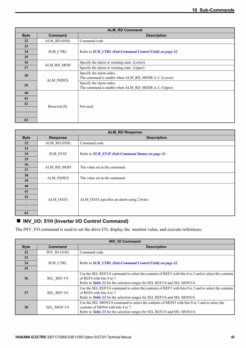
ALM_RD: 05H (Read Alarm or Warning Command)The ALM_RD command is used to read the alarm or warning state. The command can be used in communication phases 2 and 3.
The current alarm or warning state is read from ALM_DATA as an alarm or warning code. Refer to the drive instruction manual for details about ALM_DATA.
CONFIG CommandByte Command Description
0 CONFIG (04H) Command code1 WDT Watchdog data2
CMD_CTRL Refer to Command Control (CMD_CTRL) on page 273
4 CONFIG_MOD Specify the type of setup.Refer to Table 16 for details.
5
Reserved (0) Not used
67
31
CONFIG ResponseByte Command Description
0 CONFIG (04H) Command code1 RWDT Watchdog data2
CMD_STAT Refer to Command Status (CMD_STAT) on page 27. 34 CONFIG_MOD The value set in the command5
Reserved (0) Not used
67
31
CONFIG_MOD Description
0 RAM WriteThe setting value is not stored in EEPROM.
1The setting value is stored in EEPROM.
Note: The EEPROM can only be written to 100,000 times, so it is recommended to limit the number of times writing to the EEPROM. Issue the CONFIG command after changing all the parameters.
ALM_RD CommandByte Command Description
0 ALM_RD (05H) Command code1 WDT Watchdog data

9 Main Command
34 YASKAWA ELECTRIC SIEP C730600 63B V1000 Option SI-ET3/V Technical Manual
Table 17 ALM_RD_MOD
2CMD_CTRL Refer to Command Control (CMD_CTRL) on page 27.
34
ALM_RD_MODSpecify the alarm or warning state. (Lower)
5 Specify the alarm or warning state. (Upper)
6ALM_INDEX
Specify the alarm index.The command is enabled when ALM_RD_MODE is 2. (Lower)
7 Specify the alarm index.The command is enabled when ALM_RD_MODE is 2. (Upper)
8
Reserved (0) Not used
910
31
ALM_RD ResponseByte Response Description
0 ALM_RD (05H) Command code1 RWDT Watchdog data2
CMD_STAT Refer to Command Status (CMD_STAT) on page 27. 34
ALM_RD_MOD The value set in the command56
ALM_INDEX The value set in the command78
ALM_DATA ALM_DATA specifies an alarm using 2 bytes.
910
31
Byte ALM_RD_MOD = 0 ALM_RD_MOD = 1 ALM_RD_MOD = 24 00H 01H 02H5 00H 00H 00H6 – – ALM_INDEX (Lower)7 – – ALM_INDEX (Upper)
8 U2-01 (Lower) U3-01 (Lower)ALM_INDEX = 0: U2-01 (Lower)
ALM_INDEX ≠ 0: U3-(ALM_INDEX) (Lower)
9 U2-01 (Upper) U3-01 (Upper)ALM_INDEX = 0: U2-01 (Upper)
ALM_INDEX ≠ 0: U3-(ALM_INDEX) (Upper)
10 U2-02 (Lower) U3-02 (Lower) –11 U2-02 (Upper) U3-02 (Upper) –12 – U3-03 (Lower) –13 – U3-03 (Upper) –14 – U3-04 (Lower) –15 – U3-04 (Upper) –16 – U3-05 (Lower) –17 – U3-05 (Upper) –18 – U3-06 (Lower) –19 – U3-06 (Upper) –20 – U3-07 (Lower) –
ALM_RD CommandByte Command Description

9 Main Command
YASKAWA ELECTRIC SIEP C730600 63B V1000 Option SI-ET3/V Technical Manual 35
Table 18 ALM_DATA
ALM_CLR: 06H (Clear Alarm or Warning Command)The ALM_CLR command is used to clear the alarm or warning state. The command can be used in communication phases 2 and 3.
This command changes the state of a slave station, it does not remove the cause of a fault. After the cause of the alarm or warning has been removed, this command is then used to clear the status of the alarm or warning.
SYNC_SET: 0DH (Start Synchronous Communication Command)The SYNC_SET command is used to start synchronous communications. After this command is issued, synchronous communications are carried out. If communications become asynchronous due to any fault such as a communications fault, this command can be used to restore synchronous communications. The command can be used in communication phases 2 and 3. Watchdog data error detection commences when this command has been completed.
21 – U3-07 (Upper) –22 – U3-08 (Lower) –23 – U3-08 (Upper) –24 – U3-09 (Lower) –25 – U3-09 (Upper) –26 – U3-10 (Lower) –27 – U3-10 (Upper) –
ALM_RD_MOD Description0 Present fault (Byte 6), Fault history Byte 8 to 11 U2-01, U2-021 Alarm status list (Byte 8 to 27) U3-01 to U3-102 Fault history (Alarms are not saved in the history.) (Byte 8 to 9) U2-01, U3-01 to U3-10
ALM_RD CommandByte Command Description
0 ALM_RD (06H) Command code1 WDT Watchdog data2
CMD_CTRL Refer to Command Control (CMD_CTRL) on page 27.34
ALM_CLR_MOD 0: Clears the status of present faults and alarms.56
Reserved (0) Not used7
31
ALM_RD ResponseByte Command Description
0 ALM_RD (06H) Command code1 RWDT Watchdog data2
CMD_STAT Refer to Command Status (CMD_STAT) on page 27.34
ALM_CLR_MOD The value set in the command56
Reserved (0) Not used7
31
Byte ALM_RD_MOD = 0 ALM_RD_MOD = 1 ALM_RD_MOD = 2

9 Main Command
36 YASKAWA ELECTRIC SIEP C730600 63B V1000 Option SI-ET3/V Technical Manual
CONNECT: 0EH (Establish Connection Command)The CONNECT command is used to establish a MECHATROLINK connection. After the connection is established, the phase moves to communication phase 2 and 3.
SYNC_SET commandByte Command Description
0 SYNC_SET (0DH) Command code1 WDT Watchdog data2
CMD_CTRL Refer to Command Control (CMD_CTRL) on page 27. 34
Reserved (0) Not used
567
31
SYNC_SET ResponseByte Command Description
0 SYNC_SET (0DH) Command code1 RWDT Watchdog data2
CMD_STAT Refer to Command Status (CMD_STAT) on page 27. 34
Reserved (0) Not used
567
31
CONNECT CommandByte Command Description
0 CONNECT (0EH) Command code1 WDT Watchdog data2
CMD_CTRL Refer to Command Control (CMD_CTRL) on page 27.34 VER Specify 30H.
5 COM_MOD Specify the Communication Mode (COM_MOD).Refer to Table 19 for details.
6 COM_TIM 1 to 255Sets multiples of the transmission cycle as the communication cycle.
7 PROFILE_TYPE Specify PROFILE_TYPE = 20H.8
Reserved (0) Not used
31
CONNECT ResponseByte Command Description
0 CONNECT (0EH) Command code1 RWDT Watchdog data

9 Main Command
YASKAWA ELECTRIC SIEP C730600 63B V1000 Option SI-ET3/V Technical Manual 37
Table 19 COM_MOD
Table 20 COM_MOD Bits
DISCONNECT: 0FH (Release Connection Command)The DISCONNECT command is used to release the connection. When this command is completed, the communication phase shifts to communication phase 1.
INV_CTL: 50H (Inverter Operation Control Command)The INV_CTL command is used to set the drive operation signals, speed references, and so on. Units for speed reference and output frequency are determined by parameter o1-03. This command can be used in communication phases 2 and 3.
2CMD_STAT Refer to Command Status (CMD_STAT) on page 27.
34 VER The value set in the command5 COM_MOD The value set in the command6 COM_TIM The value set in the command7 PROFILE_TYPE The value set in the command8
Reserved (0) Not used
31
bit 7 bit 6 bit 5 bit 4 bit 3 bit 2 bit 1 bit 0SUBCMD 0 0 0 DTMODE SYNCMODE 0
Bit Name Value Description
SUBCMD Sub-command setting0 Sub-command disabled1 Sub-command enabled
DTMODE Data transfer method 0 Single transmission
SYNCMODE Synchronization setting0 Performs synchronous communication1 Performs asynchronous communication
DISCONNECT CommandByte Command Description
0 DISCONNECT (0FH) Command code1
Reserved (0) Not used
31
DISCONNECT ResponseByte Response Description
0 DISCONNECT (0FH) Command code1
Reserved (0) Not used
31
INV_CTL ResponseByte Response Description
0 INV_CTL (50H) Command code1 WDT Watchdog data
CONNECT ResponseByte Command Description

9 Main Command
38 YASKAWA ELECTRIC SIEP C730600 63B V1000 Option SI-ET3/V Technical Manual
INVCMD_CTRL
Table 21 INVCMD_CTRL Bits
2CMD_CTRL Refer to Command Control (CMD_CTRL) on page 27
34
INVCMD_CTRL Refer to INVCMD_CTRL on page 38.5678
INVCMD_IO Refer to INVCMD_IO Command on page 39.9101112
Speed reference
Speed Reference (Lower)13 Speed Reference (Upper)14 Not used (Set to 0.)15 Not used (Set to 0.)16
Torque reference
Torque Reference (Lower)17 Torque Reference (Upper)18 Not used (Set to 0.)19 Not used (Set to 0.)
20 SEL_REF1/2Use the SEL REF1/2 command to select the contents of REF1 with bits 0 to 3 and to select the contents of REF2 with bits 4 to 7.Refer to Table 22 for the selection ranges for SEL REF1/2 and SEL MON1/2.
21 SEL_MON1/2 Use the SEL MON1/2 command to select the contents of MON1 with bits 0 to 3 and to select the contents of MON2 with bits 4 to 7.
22Reserved (0) Not used (Set to 0.)
2324
Reference selected with SEL_REF1
Reference selected with SEL_REF1 (Lower)25 Reference selected with SEL_REF1 (Upper)26 Not used (Set to 0.)27 Not used (Set to 0.)28
Reference selected with SEL_REF2
Reference selected with SEL_REF2 (Lower)29 Reference selected with SEL_REF2 (Upper)30 Not used (Set to 0.)31 Not used (Set to 0.)
Vender Specificbit 1 bit 0
bit 7 bit 6 bit 5 bit 4 bit 3 bit 2
Not used Reverse operation
Forward operation
Vender Specificbit 9 bit 8
bit 15 bit 14 bit 13 bit 12 bit 11 bit 10Not used Refer to Table 21. Fault reset Reserved (0)
Vender Specificbit 23 bit 22 bit 21 bit 20 bit 19 bit 18 bit 17 bit 16
Not used Multi-Function Input Terminal 3 to 8bit 31 bit 30 bit 29 bit 28 bit 27 bit 26 bit 25 bit 24
Reserved (0)
Bit Name Description
0 Forward operation 0: Stop1: Forward operation
1 Reverse operation 0: Stop1: Reverse operation
9 Fault reset 1: Fault reset
INV_CTL ResponseByte Response Description

9 Main Command
YASKAWA ELECTRIC SIEP C730600 63B V1000 Option SI-ET3/V Technical Manual 39
INVCMD_IO Command
Table 22 SEL_REF Reference Data Codes
Table 23 SEL_MON Monitor Data Codes
10 External fault (EF0) 1: External fault input (EF0)11 Clear the fault history 1: Clear fault history12 External base block reference 1: External base block reference ON
16 Multi-function input terminal 3Multi-function input terminal S3 0: Multi-function input terminal S3 is OFF 1: Multi-function input terminal S3 is ON
17 Multi-function input terminal 4Multi-function input terminal S4 0: Multi-function input terminal S4 is OFF 1: Multi-function input terminal S4 is ON
18 Multi-function input terminal 5Multi-function input terminal S5 0: Multi-function input terminal S5 is OFF 1: Multi-function input terminal S5 is ON
19 Multi-function input terminal 6Multi-function input terminal S60: Multi-function input terminal S6 is OFF 1: Multi-function input terminal S6 is ON
20 Multi-function input terminal 7Multi-function input terminal S7 0: Multi-function input terminal S7 is OFF 1: Multi-function input terminal S7 is ON
21 Multi-function input terminal 8Multi-function input terminal S8 0: Multi-function input terminal S8 is OFF 1: Multi-function input terminal S8 is ON
Vender Specificbit 7 bit 6 bit 5 bit 4 bit 3 bit 2 bit 1 bit 0
Not usedVender Specific
bit 15 bit 14 bit 13 bit 12 bit 11 bit 10 bit 9 bit 8Not used
Vender Specificbit 23 bit 22 bit 21 bit 20 bit 19 bit 18 bit 17 bit 16
Not used
bit 31 bit 30 bit 29 bit 28Vender Specific
bit 27 bit 26 bit 25 bit 24Reserved (0) Not used
Selection Code Monitor Name Contents0 Nothing Selected –1 Torque Compensation Unit: 0.1%2 Analog Output Terminal 1 Output Enabled when H4-01 = 0003 Analog Output Terminal 2 Output Enabled when H4-01 = 0004 Terminal Output –5 PID Setpoint Unit: 0.01%6 Pulse Output Unit: 1 Hz7 V/f Gain –8 Not used –9 Control Selection Setting Bit 1: PID setpoint enabled
Selection Code Monitor Name Contents0 Nothing Selected –1 Motor Speed Displayed in U1-05 and determined by o1-03.2 Torque Reference (Monitor) Displayed in U1-09 (0.1%).3 Not used –4 Frequency Reference Displayed in U1-01 and determined by o1-03.5 Analog Input Terminal A2 Displayed in U1-14 (0.1%).
Bit Name Description

9 Main Command
40 YASKAWA ELECTRIC SIEP C730600 63B V1000 Option SI-ET3/V Technical Manual
INV_CTL Response
6 DC Bus Voltage Displayed in U1-07 (1 V).7 Inverter Alarm –8 Inverter Warning –9 Multi-Function Output Terminal Status Displayed in U1-11.A Analog Input Terminal Displayed in U1-15 (0.1%).
B Multi-Function Input Terminal Status S1 to S8 Displayed in U1-10.
C Analog Input Terminal Displayed in U1-13 (0.1%).D Speed Detection PG2 Counter –E Monitor Data Set to F6-23 –F Monitor Data Set to F6-24 –
INV_CTL ResponseByte Response Contents
0 INV_CTL (50H) Command code1 RWDT Watchdog data2
CMD_STAT Refer to Command Status (CMD_STAT) on page 27.34
INVCMD_STAT Refer to INVCMD_CTRL on page 38.5678
INVCMD_IO Refer to INVCMD_IO Command on page 39.9101112
Output Frequency
Output Frequency (Lower)13 Output Frequency (Upper)14 Not used (Set to 0.)15 Not used (Set to 0.)16
Output Current
Output current (Lower)17 Output current (Upper)18 Not used (Set to 0.)19 Not used (Set to 0.)20 SEL_REF1/2 The value set in the command.21 SEL_MON1/2 The value set in the command.22
Reserved (0) Not used (Set to 0.)2324
Monitor data set to SEL_MON1
Monitor data set to SEL_MON1 (Lower)25 Monitor data set to SEL_MON1 (Upper)26 Not used (Set to 0.)27 Not used (Set to 0.)28
Monitor data set to SEL_MON2
Monitor data set to SEL_MON2 (Upper)29 Monitor data set to SEL_MON2 (Upper)30 Not used (Set to 0.)31 Not used (Set to 0.)
Selection Code Monitor Name Contents

9 Main Command
YASKAWA ELECTRIC SIEP C730600 63B V1000 Option SI-ET3/V Technical Manual 41
INVCMD_STAT
INVCMD_IO Response
Vender Specificbit 1 bit 0
bit 7 bit 6 bit 5 bit 4 bit 3 bit 2
oPE Error Drive Ready Speed Agree Zero Servo Main Power Supply ON
Basblock Released
Reverse Operation
Forward Operation
Vender Specificbit 9 bit 8
bit 15 bit 14 bit 13 bit 12 bit 11 bit 10
Not used Zero Servo Motor 2 Selection
LOCAL/REMOTE
Power Loss Recovery/
Momentary Power Loss Recovery
Fault reset Signal Input Reserved (0)
Vender Specificbit 23 bit 22 bit 21 bit 20 bit 19 bit 18 bit 17 bit 16
Not usedbit 31 bit 30 bit 29 bit 28 bit 27 bit 26 bit 25 bit 24
Reserved (0) SEL_MON2 Status
SEL_MON1 Status
Bit Name Description
0 Forward Operation 0: Stop1: Forward operation in progress
1 Reverse Operation 0: Stop1: Reverse operation in progress
2 Baseblock Released 0: Baseblock1: Baseblock released
3 Main Power Supply ON 0: Main power supply OFF1: Main power supply ON
4 Zero speed 1: Zero Speed5 Speed Agree 1: Speed agree6 Drive Ready 1: Drive ready7 oPE Error 1: oPE error9 Fault Reset Signal being Input 1: Fault reset signal being input
10 Power Loss Recovery/Momentary Power Loss Recovery
0: Power loss recovery1: Momentary power loss recovery
11 LOCAL/REMOTE 0: LOCAL1: REMOTE
12 Motor 2 Selection 0: Motor 1 1: Motor 2
13 Zero Servo 1: Zero servo
24 SEL_MON1 Status 0: Disabled 1: SEL_MON1 enabled
25 SEL_MON2 Status 0: Disabled1: SEL_MON2 enabled
Vender Specificbit 7 bit 6 bit 5 bit 4 bit 3 bit 2 bit 1 bit 0
Not usedVender Specific
bit 15 bit 14 bit 13 bit 12 bit 11 bit 10 bit 9 bit 8Not used
Vender Specificbit 23 bit 22 bit 21 bit 20 bit 19 bit 18 bit 17 bit 16
Not used
bit 31 bit 30 bit 29 bit 28Vender Specific
bit 27 bit 26 bit 25 bit 24Reserved (0) Not used

42 YASKAWA ELECTRIC SIEP C730600 63B V1000 Option SI-ET3/V Technical Manual
10 Sub-Commands
10 Sub-CommandsSub-commands can be used when the 64-byte data transmission (F6-21 = 0) has been selected.
SUB_CTRL (Sub-Command Control Field)Table 24 SUB_CTRL
SUB_STAT (Sub-Command Status)Table 25 SUB_STAT
Table 26 SUBCMD_ALM
NOP: 00H (No Operation Command)The NOP command is used for network control. The current state is returned as a response. The command can be used in all communication phases.
bit 7 bit 6 bit 5 bit 4 bit 3 bit 2 bit 1 bit 0Reserved (0)
bit 15 bit 14 bit 13 bit 12 bit 11 bit 10 bit 9 bit 8Reserved (0)
bit 23 bit 22 bit21 bit 20 bit 19 bit 18 bit 17 bit 16Reserved (0)
bit 7 bit 6 bit 5 bit 4 bit 3 bit 2 bit 1 bit 0Not used (Set to 0.) Reserved (0) SUBCMDRDY Not used
bit 15 bit 14 bit 13 bit 12 bit 11 bit 10 bit 9 bit 8Reserved (0) SUBCMD_ALM
bit 23 bit 22 bit 21 bit 20 bit 19 bit 18 bit 17 bit 16Reserved (0)
Command Description
SUBCMDRDY 0: Sub-command reception disabled1: Sub-command reception enabled
SUBCMD_ALMNotifies the sub-command error state.If a normal sub-command is received after the occurrence of a sub-command error, SUBCMD_ALM is automatically cleared.
Code Contents– 0H Normal
Warning 1H Invalid data
Alarm
8H Unsupported command received9H Invalid dataAH Invalid dataBH Sub-command combination errorCH Phase error
NOP CommandByte Command Description
32 NOP (00H) Command code33
SUB_CTRL Refer to SUB_CTRL (Sub-Command Control Field) on page 42.343536
Reserved (0) Not used37
63

10 Sub-Commands
YASKAWA ELECTRIC SIEP C730600 63B V1000 Option SI-ET3/V Technical Manual 43
PRM_RD: 01H (Read Parameter Command) The PRM_RD command is used to read a parameter by specifying the parameter number and the data size. The command can be used in communication phases 2 and 3. Refer to drive instruction manual for MEMOBUS/Modbus register numbers.
PRM_WR: 02H (Write Parameter Sub-Command)The PRM_WR command is used to write a parameter by specifying the parameter number, data size, and parameter data.The command can be used in communication phases 2 and 3. After the parameters are written, the CONFIG command
NOP ResponseByte Response Description
32 NOP (00H) Command code33
SUB_STAT Refer to SUB_STAT (Sub-Command Status) on page 42.343536
Reserved (0) Not used37
63
PRM_RD CommandByte Command Description
32 PRM_RD (01H) Command code33
SUB_CTRL Refer to SUB_CTRL (Sub-Command Control Field) on page 42.343536
NOMEMOBUS/Modbus register number (Lower)
37 MEMOBUS/Modbus register number (Upper)38 SIZE Specify the parameter data size in bytes. 2, 4, 6, and 8 are available.39
Reserved (0) Not used
404142
63
PRM_RD ResponseByte Response Description
32 PRM_RD (01H) Command code33
SUB_STAT Refer to SUB_STAT (Sub-Command Status) on page 42.343536
NOThe value (Lower) set in the command.
37 The value (Upper) set in the command.38 SIZE The value set in the command.39 Reserved (0) 0 is set.40
PARAMETER
Sets the data read in the byte set in the command.The option stores the data read for PARAMETER from lower byte (LSB) to upper byte (MSB). 0 is stored when the field is not used.0 is stored in PARAMETER when command error occurs.
4142
63

10 Sub-Commands
44 YASKAWA ELECTRIC SIEP C730600 63B V1000 Option SI-ET3/V Technical Manual
must be sent to force the parameters to become effective. Refer to the drive instruction manual for details of MEMOBUS/Modbus register numbers.
In the following statuses, an alarm is detected and the command goes into error.
ALM_RD: 05H (Read Alarm or Warning Command)The ALM_RD command is used to read the alarm or warning state. The command can be used in communication phases 2 and 3.The current alarm or warning state is read to ALM_DATA as an alarm or warning code. Refer to the drive instruction manual for details about ALM_DATA.
PRM_RDA CommandByte Command Description
32 PRM_WR (02H) Command code33
SUB_CTRL Refer to SUB_CTRL (Sub-Command Control Field) on page 42.343536
NOMEMOBUS/Modbus register number (Lower)
37 MEMOBUS/Modbus register number (Upper)38 SIZE Specify the parameter data size in bytes. 2, 4, 6, and 8 are available.39 Reserved (0) Not used40
PARAMETER Specify the lower byte (LSB) before the upper byte (MSB) in the size set in the SIZE.
4142
63
PRM_WR ResponseByte Response Description
32 PRM_WR (02H) Command code33
SUB_STAT Refer to SUB_STAT (Sub-Command Status) on page 42.343536
NOThe value (Lower) set in the command.
37 The value (Upper) set in the command.38 SIZE The value set in the command.39 Reserved (0) 0 is set.40
PARAMETER The value set in the command.0 is stored when the field is not used.
4142
63
Error ResponseRegister Number Error “9” is set for SUBCMD_ALM.Bit Count Error “9” is set for SUBCMD_ALM.Data Setting Error “9” is set for SUBCMD_ALM.Write Mode Error “9” is set for SUBCMD_ALM.Writing Error during Under Voltage “9” is set for SUBCMD_ALM.Writing Error during Parameter Processing “9” is set for SUBCMD_ALM.
10 Sub-Commands
YASKAWA ELECTRIC SIEP C730600 63B V1000 Option SI-ET3/V Technical Manual 45
INV_I/O: 51H (Inverter I/O Control Command)The INV_I/O command is used to set the drive I/O, display the monitor value, and execute references.
ALM_RD CommandByte Command Description
32 ALM_RD (05H) Command code33
SUB_CTRL Refer to SUB_CTRL (Sub-Command Control Field) on page 42.343536
ALM_RD_MODSpecify the alarm or warning state. (Lower)
37 Specify the alarm or warning state. (Upper)
38ALM_INDEX
Specify the alarm index.The command is enable when ALM_RD_MODE is 2. (Lower)
39 Specify the alarm index.The command is enable when ALM_RD_MODE is 2. (Upper)
40
Reserved (0) Not used
4142
63
ALM_RD ResponseByte Response Description
32 ALM_RD (05H) Command code33
SUB_STAT Refer to SUB_STAT (Sub-Command Status) on page 42.343536
ALM_RD_MOD The value set in the command.3738
ALM_INDEX The value set in the command.3940
ALM_DATA ALM_DATA specifies an alarm using 2 bytes.
4142
63
INV_IO CommandByte Command Description
32 INV_IO (51H) Command code33
SUB_CTRL Refer to SUB_CTRL (Sub-Command Control Field) on page 42.3435
36 SEL_REF 3/4Use the SEL REF3/4 command to select the contents of REF3 with bits 0 to 3 and to select the contents of REF4 with bits 4 to 7.Refer to Table 22 for the selection ranges for SEL REF3/4 and SEL MON3/4.
37 SEL_REF 5/6Use the SEL REF5/6 command to select the contents of REF5 with bits 0 to 3 and to select the contents of REF6 with bits 4 to 7.Refer to Table 22 for the selection ranges for SEL REF5/6 and SEL MON5/6.
38 SEL_MON 3/4Use the SEL MON3/4 command to select the contents of MON3 with bits 0 to 3 and to select the contents of MON4 with bits 4 to 7.Refer to Table 23 for the selection ranges for SEL REF3/4 and SEL MON3/4.

10 Sub-Commands
46 YASKAWA ELECTRIC SIEP C730600 63B V1000 Option SI-ET3/V Technical Manual
39 SEL_MON 5/6Use the SEL MON5/6 command to select the contents of MON5 with bits 0 to 3 and to select the contents of MON6 with bits 4 to 7.Refer to Table 23 for the selection ranges for SEL REF5/6 and SEL MON5/6.
40Reference selected with
SEL_REF3
Reference selected with SEL_REF3 (Lower)41 Reference selected with SEL_REF3 (Upper)42 Not used (Ignored if a value is set.)43 Not used (Ignored if a value is set.)44
Reference selected withSEL_REF4
Reference selected with SEL_REF4 (Lower)45 Reference selected with SEL_REF4 (Upper)46 Not used (Set to 0.)47 Not used (Set to 0.)48
Reference selected withSEL_REF5
Reference selected with SEL_REF5 (Lower)49 Reference selected with SEL_REF5 (Upper)50 Not used (Set to 0.)51 Not used (Set to 0.)52
Reference selected withSEL_REF6
Reference selected with SEL_REF6 (Lower)53 Reference selected with SEL_REF6 (Upper)54 Not used (Set to 0.)55 Not used (Set to 0.)56
Reserved (0) Not used
63
INV_IO ResponseByte Command Description
32 INV_IO (51H) Command code33
SUB_STAT Refer to SUB_STAT (Sub-Command Status) on page 42.343536 SEL_REF 3/4 The value set in the command.37 SEL_REF 5/6 The value set in the command.38 SEL_MON 3/4 The value set in the command.39 SEL_MON 5/6 The value set in the command.40
Monitor data set toSEL_MON3
Monitor data set to SEL_MON3 (Lower)41 Monitor data set to SEL_MON3 (Upper)42 Not used (Set to 0.)43 Not used (Set to 0.)44
Monitor data set toSEL_MON4
Monitor data set to SEL_MON4 (Lower)45 Monitor data set to SEL_MON4 (Upper)46 Not used (Set to 0.)47 Not used (Set to 0.)48
Monitor data set toSEL_MON5
Monitor data set to SEL_MON5 (Lower)49 Monitor data set to SEL_MON5 (Upper)50 Not used (Set to 0.)51 Not used (Set to 0.)52
Monitor data set toSEL_MON6
Monitor data set to SEL_MON6 (Lower)53 Monitor data set to SEL_MON6 (Upper)54 Not used (Set to 0.)55 Not used (Set to 0.)56
Reserved (0) Not used
63
INV_IO CommandByte Command Description

11 Troubleshooting
YASKAWA ELECTRIC SIEP C730600 63B V1000 Option SI-ET3/V Technical Manual 47
11 Troubleshooting
Drive-Side Error CodesDrive-side error codes appear on the drive digital operator. Causes of the errors and corrective actions are listed in Table 27. For additional error codes that may appear on the drive digital operator, refer to the drive Technical Manual.
FaultsBoth bUS (option communication error) and EF0 (External fault input from the option) can appear as an alarm or as a fault. When a fault occurs, the digital operator ALM LED remains lit. When an alarm occurs, the ALM LED flashes.
If communication stops while the drive is running, use the following questions as a guide to help remedy the fault:
• Is the option properly installed?• Is the communication line properly connected to the option? Is it loose?• Is the controller program working? Has the controller/PLC CPU stopped?• Did a momentary power loss interrupt communications?
Table 27 Fault Display and Possible Solutions
LED Operator Display Fault Name
bUS
Option Communication Error• After establishing initial communication, the connection was lost• Only detected when the run command or frequency reference is assigned to the option
(b1-01 = 3 or b1-02 = 3)Cause Possible Solution
Master controller (PLC) has stopped communicating
• Check that power is supplied to the PLC• Check that PLC is not in program mode
Communication cable is not connected properly • Check for faulty wiring• Correct any wiring problems
A data error occurred due to electric interference
• Inspect items that can minimize the effects of electrical noise• Counteract noise in the control circuit, main circuit, and ground wiring• If a magnetic contactor is identified as a source of noise, install a surge absorber to the
contactor coil• Make sure the cable used meets the MECHATROLINK-III requirements• Make sure the option ground wire is connected between option FE terminal and the drive
ground terminal connected to earth groundOption is damaged If there are no problems with the wiring and the error continues to occur, replace the option.
Connection Time-out • The option Requested Packet Interval (RPI) timer timed out• Make sure that RPI time is set properly
Duplicate Station Address Check if the option shares Station Address with at least one other node. Check the setting values of F6-20.
LED Operator Display Fault Name
E5MECHATROLINK Watchdog Timer ErrorThe watchdog has timed out.
Cause Possible SolutionData has not been received from the PLC, triggering the watchdog timer.
⇒ Execute DISCONNECT or ALM_CLR, then issue a CONNECT command or SYNC_SET command and proceed to phase 3.
LED Operator Display Fault Name
EF0Option Card External FaultThe alarm function for an external device has been triggered.
Cause Corrective ActionAn external fault is being sent from the upper controller (PLC)
• Remove the cause of the external fault• Reset the external fault input from the PLC device
Problem with the PLC program Check the program used by the PLC and make the appropriate corrections.
PLC is in the Idle Mode.• Set the PLC to the Run Mode• Set the drive parameter F6-54 to 0 (Enabled) not to detect errors while the PLC is in the Idle
Mode

11 Troubleshooting
48 YASKAWA ELECTRIC SIEP C730600 63B V1000 Option SI-ET3/V Technical Manual
Minor Faults and Alarms
LED Operator Display Fault Name
oFA00Option Card FaultOption is not properly connected.
Cause Possible SolutionNon-compatible option connected to the drive Connect an option that is compatible with the drive.
LED Operator Display Fault Name
oFA01Option Card FaultOption is not properly connected.
Cause Possible SolutionProblem with the connectors between the drive and option Turn the power off and check the connectors between the drive and option.
LED Operator Display Fault Name
to oFA30 to oFA43Option Card Fault
Communication ID error.
Cause Possible SolutionOption hardware fault Replace the option.
LED Operator Display Minor Fault Name
CALLSerial communication transmission errorCommunication is not established.
Cause Possible Solution Minor Fault (H2- = 10)
Communication wiring is faulty, there is a short circuit, or improper connection.
Check for wiring errors:• Correct the wiring• Remove ground shorts and reconnect loose wires
YESProgramming error on the master side. Check communications at start-up and correct programming errors.
Communication circuitry is damaged. • Perform a self-diagnostics check• Replace the drive if the fault continues to occur
LED Operator Display Minor Fault Name
CYCTransmission Cycle Setting ErrorTransmission cycle from the master controller (PLC) was out of range.
Cause Possible Solution Minor Fault (H2- = 10)
Transmission cycle of the option set in the master controller (PLC) was out of range.
Set the transmission cycle of the master controller in the range of 250 μs, 500 μs, 750 μs, and 1 to 32 ms (0.5 ms increment). Make sure to set the communication cycle to 32 ms or less.
YES

12 Specifications
YASKAWA ELECTRIC SIEP C730600 63B V1000 Option SI-ET3/V Technical Manual 49
12 Specifications
SpecificationsTable 28 Option Specifications
Item
<1> The maximum number of connectable stations changes depending on the types and settings of the host controller, baud rate, or communications cycle. For details, refer to the controller manual.
SpecificationModel SI-ET3/VAccess mode Start-stop synchronization, master/slave methodCommunication speed 100 MbpsMinimum transmission cycle 250 μsMaximum transmission cycle 8 msTransmission cycle granularity 03HMinimum wiring distance between stations 0.2 m (7.9 in.)
Maximum wiring distance between stations 100 m (3937.0 in.)
Data length 32-byte data transmission or 64-byte data transmissionEvent driven communication ValidProfile Compliant with standard inverter profileMaximum number of stations 62 <1>
Ambient temperature -10°C to +50°C (14°F to 122°F)Humidity 95% RH or lower with no condensationStorage temperature -20°C to +60°C (-4°F to 140°F) allowed for short-term transport of the productArea of use Indoor (free of corrosive gas, airborne particles, etc.)Altitude 1000 m (3280 ft.) or lower

12 Specifications
50 YASKAWA ELECTRIC SIEP C730600 63B V1000 Option SI-ET3/V Technical Manual
Revision HistoryThe revision dates and the numbers of the revised manuals appear on the bottom of the back cover.
Date of Publication Revision Number Section Revised Content
September 2013 All Revision: Manual numberJune 2013 − − First edition
Published in Japan September 2013 13-6
Date of publicationDate of original publication
MANUAL NO. SIEP C730600 63B
Revision number
1 V1000
1

DRIVE CENTER (INVERTER PLANT)2-13-1, Nishimiyaichi, Yukuhashi, Fukuoka, 824-8511, JapanPhone: 81-930-25-3844 Fax: 81-930-25-4369http://www.yaskawa.co.jp
YASKAWA ELECTRIC CORPORATIONNew Pier Takeshiba South Tower, 1-16-1, Kaigan, Minatoku, Tokyo, 105-6891, JapanPhone: 81-3-5402-4502 Fax: 81-3-5402-4580http://www.yaskawa.co.jp
YASKAWA AMERICA, INC.2121 Norman Drive South, Waukegan, IL 60085, U.S.A.Phone: 1-800-YASKAWA (927-5292) or 1-847-887-7000 Fax: 1-847-887-7310http://www.yaskawa.com
YASKAWA ELÉTRICO DO BRASIL LTDA.Avenida Piraporinha 777, Diadema, São Paulo, 09950-000, BrasilPhone: 55-11-3585-1100 Fax: 55-11-3585-1187http://www.yaskawa.com.br
YASKAWA EUROPE GmbHHauptstrasse 185, 65760 Eschborn, GermanyPhone: 49-6196-569-300 Fax: 49-6196-569-398http://www.yaskawa.eu.com
YASKAWA ELECTRIC KOREA CORPORATION9F, Kyobo Securities Bldg., 26-4, Yeouido-dong, Yeongdeungpo-gu, Seoul, 150-737, KoreaPhone: 82-2-784-7844 Fax: 82-2-784-8495http://www.yaskawa.co.kr
YASKAWA ELECTRIC (SINGAPORE) PTE. LTD.151 Lorong Chuan, #04-02A, New Tech Park, 556741, SingaporePhone: 65-6282-3003 Fax: 65-6289-3003http://www.yaskawa.com.sg
YASKAWA ELECTRIC (CHINA) CO., LTD.12F, Carlton Bld., No.21 HuangHe Road, HuangPu District, Shanghai 200003, ChinaPhone: 86-21-5385-2200 Fax: 86-21-5385-3299http://www.yaskawa.com.cn
YASKAWA ELECTRIC (CHINA) CO., LTD. BEIJING OFFICERoom 1011, Tower W3 Oriental Plaza, No. 1 East Chang An Ave., Dong Cheng District, Beijing, 100738, ChinaPhone: 86-10-8518-4086 Fax: 86-10-8518-4082
YASKAWA ELECTRIC TAIWAN CORPORATION9F, 16, Nanking E. Rd., Sec. 3, Taipei, 104, TaiwanPhone: 886-2-2502-5003 Fax: 886-2-2505-1280
YASKAWA INDIA PRIVATE LIMITED#17/A Electronics City, Hosur Road Bangalore 560 100 (Karnataka), IndiaPhone: 91-80-4244-1900 Fax: 91-80-4244-1901http://www.yaskawaindia.in
In the event that the end user of this product is to be the military and said product is to be employed in any weapons systems or the manufacture thereof, the export will fall under the relevant regulations as stipulated in the Foreign Exchange and Foreign Trade Regulations. Therefore, be sure to follow all procedures and submit all relevant documentation according to any and all rules, regulations and laws that may apply.
Specifications are subject to change without notice for ongoing product modifications and improvements.
© 2013 YASKAWA ELECTRIC CORPORATION. All rights reserved.
Published in Japan September 2013 13-6
MANUAL NO. SIEP C730600 63B
13-7-111 -0
YASKAWA ELECTRIC CORPORATION
MECHATROLINK-IIIYASKAWA AC Drive-V1000 Option
Technical Manual