YASKAWA AC Drive – J1000 - Brammer · YASKAWA AC Drive – J1000 Compact V/f Control Drive...
230
YASKAWA AC Drive – J1000 Compact V/f Control Drive Technical Manual Type: CIMR-JC Model: 200 V Class, Single-Phase Input: 0.1 to 2.2 kW 200 V Class, Three-Phase Input: 0.1 to 5.5 kW 400 V Class, Three-Phase Input: 0.2 to 5.5 kW To properly use the product, read this manual thoroughly and retain for easy reference, inspection, and maintenance. Ensure the end user receives this manual. MANUAL NO. SIEP C710606 32A Receiving 1 Mechanical Installation 2 Electrical Installation 3 Start-Up Programming & Operation 4 Parameter Details 5 Troubleshooting 6 Periodic Inspection & Maintenance 7 Peripheral Devices & Options 8 Specifications A Parameter List B MEMOBUS/Modbus Communications C Standards Compliance D
-
Upload
nguyennguyet -
Category
Documents
-
view
231 -
download
1
Transcript of YASKAWA AC Drive – J1000 - Brammer · YASKAWA AC Drive – J1000 Compact V/f Control Drive...
YASKAWA AC Drive – J1000Compact V/f Control DriveTechnical ManualType: CIMR-JC Model: 200 V Class, Single-Phase Input: 0.1 to 2.2 kW
200 V Class, Three-Phase Input: 0.1 to 5.5 kW400 V Class, Three-Phase Input: 0.2 to 5.5 kW
To properly use the product, read this manualthoroughly and retain for easy reference,inspection, and maintenance. Ensure the enduser receives this manual.
MANUAL NO. SIEP C710606 32A
Receiving 1
Mechanical Installation 2
Electrical Installation 3Start-Up Programming &
Operation 4
Parameter Details 5
Troubleshooting 6Periodic Inspection &
Maintenance 7Peripheral Devices &
Options 8
Specifications A
Parameter List BMEMOBUS/Modbus
Communications C
Standards Compliance D
This Page Intentionally Blank
2 YASKAWA ELECTRIC SIEP C710606 32A YASKAWA AC Drive – J1000 Technical Manual
Copyright © 2008 YASKAWA ELECTRIC CORPORATION. All rights reserved.All rights reserved. No part of this publication may be reproduced, stored in a retrieval system, or transmitted,in any form or by any means, mechanical, electronic, photocopying, recording, or otherwise, without the priorwritten permission of Yaskawa. No patent liability is assumed with respect to the use of the informationcontained herein. Moreover, because Yaskawa is constantly striving to improve its high-quality products, theinformation contained in this manual is subject to change without notice. Every precaution has been taken inthe preparation of this manual. Yaskawa assumes no responsibility for errors or omissions. Neither is any liabilityassumed for damages resulting from the use of the information contained in this publication.

Table of Contentsi. PREFACE & GENERAL SAFETY................................................................9
i.1 Preface .................................................................................................................. 10Applicable Documentation..................................................................................................10Symbols..............................................................................................................................10Terms and Abbreviations ...................................................................................................10
i.2 General Safety ...................................................................................................... 11Supplemental Safety Information .......................................................................................11Safety Messages................................................................................................................11Drive Label Warnings .........................................................................................................13Warranty Information..........................................................................................................13Quick Reference.................................................................................................................13
1. RECEIVING ................................................................................................151.1 Section Safety....................................................................................................... 161.2 Model Number and Nameplate Check ................................................................ 17
Nameplate ..........................................................................................................................171.3 Component Names............................................................................................... 19
IP20/Open-Chassis ............................................................................................................19Front Views ........................................................................................................................21
2. MECHANICAL INSTALLATION.................................................................232.1 Section Safety....................................................................................................... 242.2 Mechanical Installation ........................................................................................ 26
Installation Environment .....................................................................................................26Installation Orientation and Spacing...................................................................................27Exterior and Mounting Dimensions ....................................................................................27
3. ELECTRICAL INSTALLATION ..................................................................293.1 Section Safety....................................................................................................... 303.2 Standard Connection Diagram............................................................................ 323.3 Main Circuit Connection Diagram....................................................................... 34
Single-Phase 200 V Class (CIMR-JoBA0001 ~ 0010)......................................................34Three-Phase 200 V Class (CIMR-Jo2A0001 ~0020);Three-Phase 400 V Class (CIMR-Jo4A0001 ~ 0011)......................................................34
3.4 Terminal Block Configuration ............................................................................. 353.5 Protective Covers................................................................................................. 36
IP20/Open-Chassis Cover Removal and Installation .........................................................363.6 Main Circuit Wiring............................................................................................... 37
Main Circuit Terminal Functions.........................................................................................37
YASKAWA ELECTRIC SIEP C710606 32A YASKAWA AC Drive – J1000 Technical Manual 3
Wire Gauges and Tightening Torque ...........................................................................................37Main Circuit Terminal Power Supply and Motor Wiring................................................................38
3.7 Control Circuit Wiring ................................................................................................... 40Control Circuit Terminal Block Functions .....................................................................................40Terminal Configuration .................................................................................................................41Wiring Procedure..........................................................................................................................42
3.8 I/O Connections............................................................................................................. 44Sinking/Sourcing Mode Switch.....................................................................................................44
3.9 Main Frequency Reference........................................................................................... 46DIP Switch S1 Analog Input Signal Selection ..............................................................................46
3.10 Braking Resistor............................................................................................................ 47Installation ....................................................................................................................................47
3.11 Interlocking with Connected Machinery ..................................................................... 48Drive Ready Signal.......................................................................................................................48
3.12 Wiring Checklist ............................................................................................................ 494. START-UP PROGRAMMING & OPERATION ..................................................51
4.1 Section Safety................................................................................................................ 524.2 Using the Digital LED Operator.................................................................................... 54
Keys, Displays, and LEDs ............................................................................................................54Digital Text Display.......................................................................................................................55LED Screen Displays ...................................................................................................................55LO/RE LED and RUN LED Indications.........................................................................................55Menu Structure for Digital LED Operator .....................................................................................56
4.3 The Drive and Programming Modes............................................................................ 57Navigating the Drive and Programming Modes............................................................................57Changing Parameter Settings or Values ......................................................................................59Verifying Parameter Changes: Verify Menu .................................................................................59Switching Between LOCAL and REMOTE...................................................................................60Parameters Available in the Setup Group ....................................................................................60
4.4 Start-up Flowchart......................................................................................................... 62Flowchart: Basic Start-up .............................................................................................................62
4.5 Powering Up the Drive .................................................................................................. 63Powering Up the Drive and Operation Status Display..................................................................63V/f Pattern Setting ........................................................................................................................63
4.6 No-Load Operation Test Run........................................................................................ 64No-Load Operation Test Run .......................................................................................................64
4.7 Test Run with Load Connected.................................................................................... 65Test Run with the Load Connected ..............................................................................................65
4.8 Verifying and Backing Up Parameter Settings ........................................................... 66Parameter Access Level: A1-01...................................................................................................66Password Settings: A1-04, A1-05 ................................................................................................66Copy Function (Optional) .............................................................................................................66
4.9 Test Run Checklist ........................................................................................................ 675. PARAMETER DETAILS .....................................................................................69
5.1 A: Initialization............................................................................................................... 70A1: Initialization ............................................................................................................................70
5.2 b: Application................................................................................................................. 72b1: Mode of Operation..................................................................................................................72b2: DC Injection Braking...............................................................................................................76
Table of Contents
4 YASKAWA ELECTRIC SIEP C710606 32A YASKAWA AC Drive – J1000 Technical Manual
5.3 C: Tuning........................................................................................................................ 77C1: Acceleration and Deceleration Times ....................................................................................77C2: S-Curve Characteristics.........................................................................................................77C3: Slip Compensation.................................................................................................................78C4: Torque Compensation ...........................................................................................................78C6: Carrier Frequency..................................................................................................................79
5.4 d: Reference Settings ................................................................................................... 82d1: Frequency Reference.............................................................................................................82d2: Frequency Upper/Lower Limits ..............................................................................................83d3: Jump Frequency.....................................................................................................................84d4: Frequency Hold Function .......................................................................................................84
5.5 E: Motor Parameters ..................................................................................................... 86E1: V/f Characteristics..................................................................................................................86E2: Motor 1 Parameters ...............................................................................................................88
5.6 H: Terminal Functions................................................................................................... 90H1: Multi-Function Digital Inputs ..................................................................................................90H2: Multi-Function Output ............................................................................................................95H3: Analog Input Terminal A1 Settings ........................................................................................98H4: Multi-Function Analog Output Terminal AM.........................................................................101H5: MEMOBUS/Modbus Serial Communication ........................................................................101
5.7 L: Protection Functions .............................................................................................. 102L1: Motor Protection Functions ..................................................................................................102L2: Momentary Power Loss Ride-Thru.......................................................................................103L3: Stall Prevention ....................................................................................................................104L4: Speed Agree ........................................................................................................................106L5: Fault Restart.........................................................................................................................107L6: Torque Detection..................................................................................................................108L8: Hardware Protection.............................................................................................................109
5.8 n: Special Adjustments............................................................................................... 112n1: Hunting Prevention...............................................................................................................112n3: Overexcitation Deceleration .................................................................................................112
5.9 o: Operator Related Settings...................................................................................... 113o1: Display Settings and Selections ...........................................................................................113o2: Operator Key Selections ......................................................................................................113o3: Copy Function ......................................................................................................................114o4: Maintenance Monitor Settings..............................................................................................115
5.10 U: Monitor Parameters................................................................................................ 117U1: Operation Status Monitors ...................................................................................................117U2: Fault History.........................................................................................................................117U4: Maintenance Monitors .........................................................................................................117
6. TROUBLESHOOTING......................................................................................1196.1 Section Safety.............................................................................................................. 1206.2 Motor Performance Fine Tuning ................................................................................ 122
Parameters for Tuning the Drive ................................................................................................122Motor Hunting and Oscillation Control Parameters ....................................................................122
6.3 Drive Alarms, Faults, and Errors ............................................................................... 123Types of Alarms, Faults, and Errors...........................................................................................123Alarm and Error Displays ...........................................................................................................123
6.4 Fault Detection ............................................................................................................ 125Fault Displays, Causes and Possible Solutions .........................................................................125
6.5 Alarm Detection........................................................................................................... 131
Table of Contents
YASKAWA ELECTRIC SIEP C710606 32A YASKAWA AC Drive – J1000 Technical Manual 5
Alarm Codes, Causes, and Possible Solutions ..........................................................................1316.6 Operator Programming Errors ................................................................................... 134
oPE Codes, Causes, and Possible Solutions.............................................................................1346.7 Diagnosing and Resetting Faults............................................................................... 135
Fault Occurs Simultaneously with Power Loss ..........................................................................135If the Drive Still has Power After a Fault Occurs ........................................................................135Viewing Fault History Data After Fault .......................................................................................135Fault Reset Methods ..................................................................................................................135
6.8 Troubleshooting without Fault Display..................................................................... 136Cannot Change Parameter Settings ..........................................................................................136Motor Does Not Rotate Properly after Pressing RUN Button or after Entering External RunCommand .................................................................................................................................136
7. PERIODIC INSPECTION & MAINTENANCE ..................................................1417.1 Section Safety.............................................................................................................. 1427.2 Inspection .................................................................................................................... 144
Recommended Daily Inspection.................................................................................................144Recommended Periodic Inspection............................................................................................144
7.3 Periodic Maintenance ................................................................................................. 146Replacement Parts.....................................................................................................................146
7.4 Drive Cooling Fans...................................................................................................... 147Cooling Fan Replacement..........................................................................................................147
8. PERIPHERAL DEVICES & OPTIONS ............................................................1498.1 Section Safety.............................................................................................................. 1508.2 Drive Options and Peripheral Devices ...................................................................... 1528.3 Connecting Peripheral Devices ................................................................................. 1538.4 Installing Peripheral Devices ..................................................................................... 154
Installing a Molded Case Circuit Breaker (MCCB) .....................................................................154Installing a Leakage Breaker......................................................................................................154Installing a Magnetic Contactor ..................................................................................................154Connecting an AC or DC Reactor ..............................................................................................155Connecting a Surge Protector ....................................................................................................155Connecting a Noise Filter ...........................................................................................................155Installing Fuses on the Input Side ..............................................................................................157Installing a Motor Thermal Overload (oL) Relay on the Drive Output ........................................157NEMA Type 1 Kit........................................................................................................................158
8.5 Communication Options............................................................................................. 161A. SPECIFICATIONS ............................................................................................163
A.1 Heavy Duty and Normal Duty Ratings....................................................................... 164A.2 Single/Three-Phase 200 V Class Drive ...................................................................... 165A.3 Three-Phase 400 V Class Drives................................................................................ 166A.4 Drive Specifications .................................................................................................... 167A.5 Drive Watt Loss Data .................................................................................................. 169A.6 Drive Derating Data ..................................................................................................... 170
Temperature Derating ................................................................................................................170
B. PARAMETER LIST...........................................................................................171B.1 Parameter Groups ....................................................................................................... 172B.2 Parameter Table .......................................................................................................... 173
A: Initialization Parameters.........................................................................................................173
Table of Contents
6 YASKAWA ELECTRIC SIEP C710606 32A YASKAWA AC Drive – J1000 Technical Manual
b: Application..............................................................................................................................173C: Tuning....................................................................................................................................174d: References .............................................................................................................................175E: Motor Parameters ..................................................................................................................176H Parameters: Multi-Function Terminals....................................................................................177L: Protection Function ................................................................................................................179n: Advanced Performance Set-Up..............................................................................................182o: Operator Related Parameters ................................................................................................182U: Monitors .................................................................................................................................183
B.3 Defaults by Drive Capacity (o2-04) and ND/HD (C6-01) ........................................... 185C. MEMOBUS/MODBUS COMMUNICATIONS....................................................187
C.1 Section Safety.............................................................................................................. 188C.2 MEMOBUS/Modbus Configuration ............................................................................ 189C.3 Communication Specifications.................................................................................. 190C.4 Connecting to a Network ............................................................................................ 191
Network Cable Connection.........................................................................................................191Wiring Diagram for Multiple Connection.....................................................................................191Network Termination ..................................................................................................................192
C.5 MEMOBUS/Modbus Setup Parameters ..................................................................... 193MEMOBUS/Modbus Serial Communication...............................................................................193
C.6 Drive Operations by MEMOBUS/Modbus.................................................................. 195Observing the Drive Operation...................................................................................................195Controlling the Drive...................................................................................................................195
C.7 Communications Timing............................................................................................. 196Command Messages from Master to Drive................................................................................196Response Messages from Drive to Master ................................................................................196
C.8 Message Format .......................................................................................................... 197Message Content .......................................................................................................................197Slave Address ............................................................................................................................197Function Code ............................................................................................................................197Data............................................................................................................................................197Error Check ................................................................................................................................197
C.9 Message Examples ..................................................................................................... 199Reading Drive MEMOBUS/Modbus Register Contents .............................................................199Loopback Test............................................................................................................................199Writing to Multiple Registers.......................................................................................................200
C.10 MEMOBUS/Modbus Data Table.................................................................................. 201Command Data ..........................................................................................................................201Monitor Data...............................................................................................................................202Broadcast Messages..................................................................................................................205Fault History Contents................................................................................................................205Alarm Register Contents ............................................................................................................206
C.11 Changing Drive Parameters ....................................................................................... 207Drive Operations on Parameter Change ....................................................................................207Issuing an Enter Command........................................................................................................207
C.12 Communication Errors ............................................................................................... 208MEMOBUS/Modbus Error Codes...............................................................................................208Slave Not Responding................................................................................................................208
C.13 Self-Diagnostics .......................................................................................................... 209D. STANDARDS COMPLIANCE ..........................................................................211
Table of Contents
YASKAWA ELECTRIC SIEP C710606 32A YASKAWA AC Drive – J1000 Technical Manual 7
D.1 Section Safety.............................................................................................................. 212D.2 European Standards ................................................................................................... 214
CE Low Voltage Directive Compliance.......................................................................................214EMC Guidelines Compliance .....................................................................................................214
D.3 UL Standards ............................................................................................................... 219UL Standards Compliance .........................................................................................................219Drive Motor Overload Protection ................................................................................................220
D.4 User Setting Table....................................................................................................... 222INDEX ...............................................................................................................225
Table of Contents
8 YASKAWA ELECTRIC SIEP C710606 32A YASKAWA AC Drive – J1000 Technical Manual

Preface & General SafetyThis section provides safety messages pertinent to this product that, if not heeded, may result infatality, personal injury, or equipment damage. Yaskawa is not responsible for the consequencesof ignoring these instructions.
I.1 PREFACE..........................................................................................................10I.2 GENERAL SAFETY..........................................................................................11
i
YASKAWA ELECTRIC SIEP C710606 32A YASKAWA AC Drive – J1000 Technical Manual 9
i.1 PrefaceYaskawa manufactures products used as components in a wide variety of industrial systems and equipment. The selectionand application of Yaskawa products remain the responsibility of the equipment manufacturer or end user. Yaskawa acceptsno responsibility for the way its products are incorporated into the final system design. Under no circumstances shouldany Yaskawa product be incorporated into any product or design as the exclusive or sole safety control. Without exception,all controls should be designed to detect faults dynamically and fail safely under all circumstances. All systems orequipment designed to incorporate a product manufactured by Yaskawa must be supplied to the end user with appropriatewarnings and instructions as to the safe use and operation of that part. Any warnings provided by Yaskawa must be promptlyprovided to the end user. Yaskawa offers an express warranty only as to the quality of its products in conforming tostandards and specifications published in the Yaskawa manual. NO OTHER WARRANTY, EXPRESSED OR IMPLIED,IS OFFERED. Yaskawa assumes no liability for any personal injury, property damage, losses, or claims arising frommisapplication of its products.
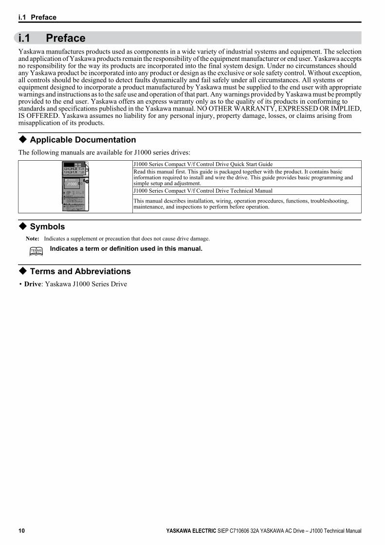
u Applicable DocumentationThe following manuals are available for J1000 series drives:
J1000 Series Compact V/f Control Drive Quick Start GuideRead this manual first. This guide is packaged together with the product. It contains basicinformation required to install and wire the drive. This guide provides basic programming andsimple setup and adjustment.J1000 Series Compact V/f Control Drive Technical Manual
This manual describes installation, wiring, operation procedures, functions, troubleshooting,maintenance, and inspections to perform before operation.
u SymbolsNote: Indicates a supplement or precaution that does not cause drive damage.
TERMSTERMS Indicates a term or definition used in this manual.
u Terms and Abbreviations• Drive: Yaskawa J1000 Series Drive
i.1 Preface
10 YASKAWA ELECTRIC SIEP C710606 32A YASKAWA AC Drive – J1000 Technical Manual
i.2 General Safety
u Supplemental Safety InformationGeneral Precautions
• The diagrams in this manual may be indicated without covers or safety shields to show details. Restore covers or shields beforeoperating the drive and run the drive according to the instructions described in this manual.
• Any illustrations, photographs, or examples used in this manual are provided as examples only and may not apply to all productsto which this manual is applicable.
• The products and specifications described in this manual or the content and presentation of the manual may be changed withoutnotice to improve the product and/or the manual.
• When ordering a new copy of the manual due to damage or loss, contact your Yaskawa representative or the nearest Yaskawa salesoffice and provide the manual number shown on the front cover.
• If nameplate becomes worn or damaged, order a replacement from your Yaskawa representative or the nearest Yaskawa sales office.
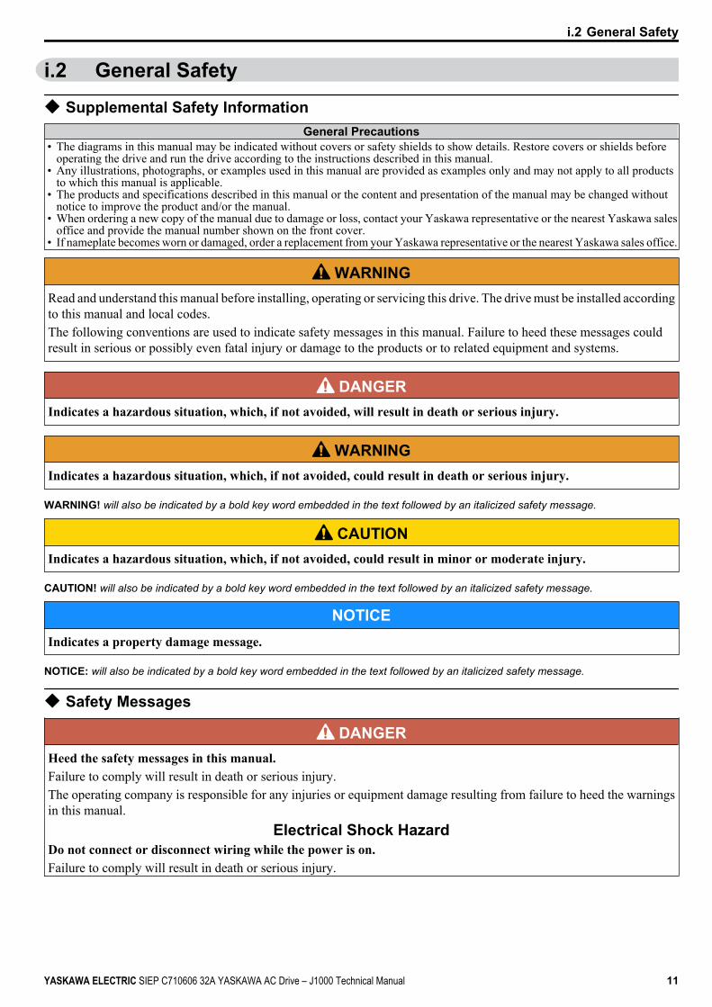
WARNINGRead and understand this manual before installing, operating or servicing this drive. The drive must be installed accordingto this manual and local codes.The following conventions are used to indicate safety messages in this manual. Failure to heed these messages couldresult in serious or possibly even fatal injury or damage to the products or to related equipment and systems.
DANGERIndicates a hazardous situation, which, if not avoided, will result in death or serious injury.
WARNINGIndicates a hazardous situation, which, if not avoided, could result in death or serious injury.
WARNING! will also be indicated by a bold key word embedded in the text followed by an italicized safety message.
CAUTIONIndicates a hazardous situation, which, if not avoided, could result in minor or moderate injury.
CAUTION! will also be indicated by a bold key word embedded in the text followed by an italicized safety message.
NOTICEIndicates a property damage message.
NOTICE: will also be indicated by a bold key word embedded in the text followed by an italicized safety message.
u Safety Messages
DANGERHeed the safety messages in this manual.Failure to comply will result in death or serious injury.The operating company is responsible for any injuries or equipment damage resulting from failure to heed the warningsin this manual.
Electrical Shock HazardDo not connect or disconnect wiring while the power is on.Failure to comply will result in death or serious injury.
i.2 General Safety
YASKAWA ELECTRIC SIEP C710606 32A YASKAWA AC Drive – J1000 Technical Manual 11

DANGERBefore servicing, disconnect all power to the equipment. The internal capacitor remains charged even after the powersupply is turned off. The charge indicator LED will extinguish when the DC bus voltage is below 50 Vdc. To preventelectric shock, wait at least one minute after all indicators are OFF and measure the DC bus voltage level to confirm safelevel.
WARNINGSudden Movement Hazard
System may start unexpectedly upon application of power, resulting in death or serious injury.Clear all personnel from the drive, motor and machine area before applying power. Secure covers, couplings, shaft keysand machine loads before applying power to the drive.
Electrical Shock HazardDo not attempt to modify or alter the drive in any way not explained in this manual.Failure to comply could result in death or serious injury.Yaskawa is not responsible for any modification of the product made by the user. This product must not be modified.Do not allow unqualified personnel to use equipment.Failure to comply could result in death or serious injury.Maintenance, inspection, and replacement of parts must be performed only by authorized personnel familiar withinstallation, adjustment and maintenance of AC drives.Do not remove covers or touch circuit boards while the power is on.Failure to comply could result in death or serious injury.
Fire HazardDo not use an improper voltage source.Failure to comply could result in death or serious injury by fire.Verify that the rated voltage of the drive matches the voltage of the incoming power supply before applying power.
Crush HazardDo not use this drive in lifting applications without installing external safety circuitry to prevent accidentaldropping of the load.The drive does not possess built-in load drop protection for lifting applications.Failure to comply could result in death or serious injury from falling loads.Install electrical and/or mechanical safety circuit mechanisms independent of drive circuitry.
CAUTIONCrush Hazard
Do not carry the drive by the front cover.Failure to comply may result in minor or moderate injury from the main body of the drive falling.
NOTICEObserve proper electrostatic discharge procedures (ESD) when handling the drive and circuit boards.Failure to comply may result in ESD damage to the drive circuitry.Never connect or disconnect the motor from the drive while the drive is outputting voltage.Improper equipment sequencing could result in damage to the drive.Do not perform a withstand voltage test on any part of the drive.Failure to comply could result in damage to the sensitive devices within the drive.Do not operate damaged equipment.Failure to comply could result in further damage to the equipment.Do not connect or operate any equipment with visible damage or missing parts.
i.2 General Safety
12 YASKAWA ELECTRIC SIEP C710606 32A YASKAWA AC Drive – J1000 Technical Manual
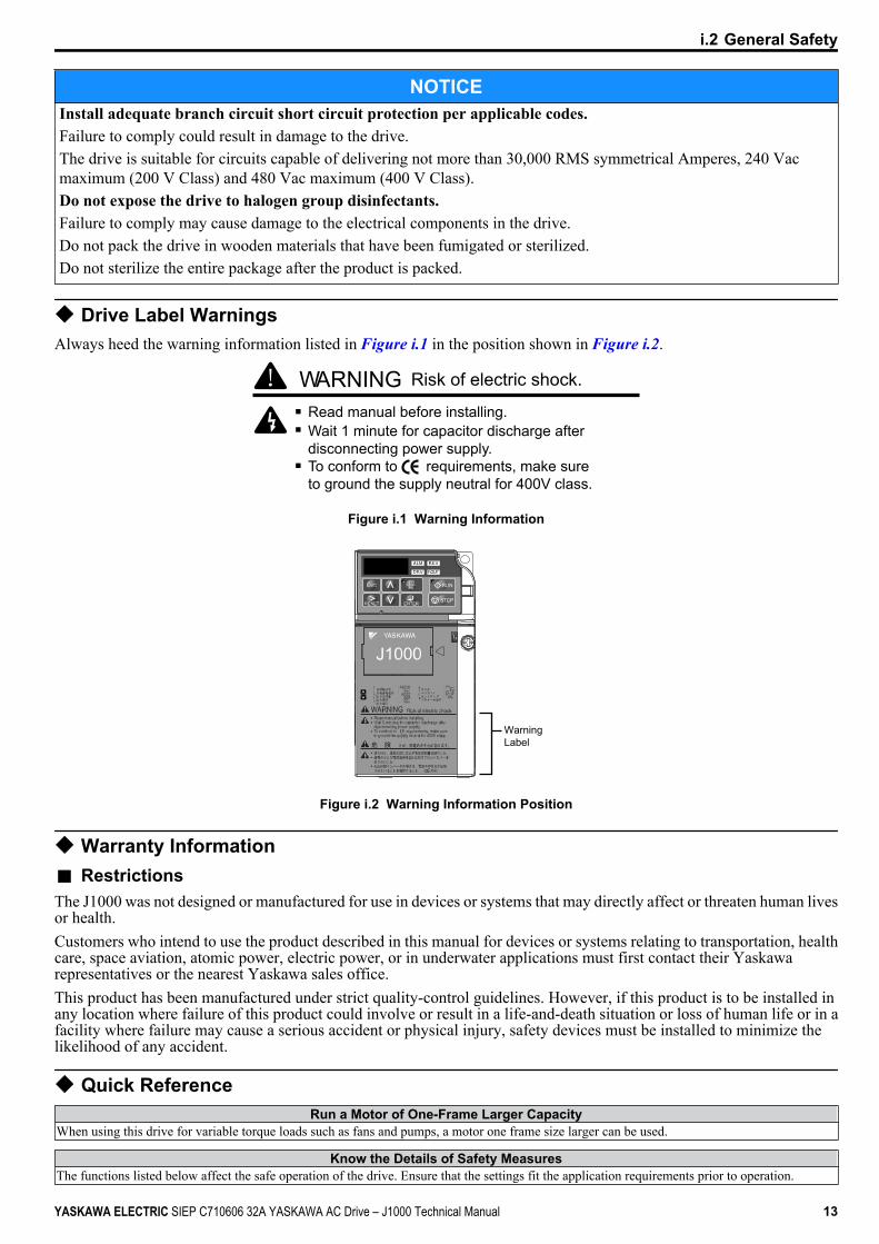
NOTICEInstall adequate branch circuit short circuit protection per applicable codes.Failure to comply could result in damage to the drive.The drive is suitable for circuits capable of delivering not more than 30,000 RMS symmetrical Amperes, 240 Vacmaximum (200 V Class) and 480 Vac maximum (400 V Class).Do not expose the drive to halogen group disinfectants.Failure to comply may cause damage to the electrical components in the drive.Do not pack the drive in wooden materials that have been fumigated or sterilized.Do not sterilize the entire package after the product is packed.
u Drive Label WarningsAlways heed the warning information listed in Figure i.1 in the position shown in Figure i.2.
Risk of electric shock.WARNINGRead manual before installing.Wait 1 minute for capacitor discharge afterdisconnecting power supply.To conform to requirements, make sureto ground the supply neutral for 400V class.
Figure i.1 Warning Information
WarningLabel
Figure i.2 Warning Information Position
u Warranty Informationn RestrictionsThe J1000 was not designed or manufactured for use in devices or systems that may directly affect or threaten human livesor health.Customers who intend to use the product described in this manual for devices or systems relating to transportation, healthcare, space aviation, atomic power, electric power, or in underwater applications must first contact their Yaskawarepresentatives or the nearest Yaskawa sales office.This product has been manufactured under strict quality-control guidelines. However, if this product is to be installed inany location where failure of this product could involve or result in a life-and-death situation or loss of human life or in afacility where failure may cause a serious accident or physical injury, safety devices must be installed to minimize thelikelihood of any accident.
u Quick ReferenceRun a Motor of One-Frame Larger Capacity
When using this drive for variable torque loads such as fans and pumps, a motor one frame size larger can be used.
Know the Details of Safety MeasuresThe functions listed below affect the safe operation of the drive. Ensure that the settings fit the application requirements prior to operation.
i.2 General Safety
YASKAWA ELECTRIC SIEP C710606 32A YASKAWA AC Drive – J1000 Technical Manual 13
Know the Details of Safety MeasuresSafe operations. Run by power on. Parameter setting b1-17.LED operator stop key priority selection. Parameter o2-02.Enter press required after changing the keypad frequency reference. Parameter o2-05.Operation interlock when program mode is selected. Parameter b1-08.
Standards Compliance
Refer to European Standards on page 214 and Refer to UL Standards on page 219.U LC R US
LISTED
i.2 General Safety
14 YASKAWA ELECTRIC SIEP C710606 32A YASKAWA AC Drive – J1000 Technical Manual
ReceivingThis chapter describes the proper inspections to perform after receiving the drive and illustratesthe different enclosure types and components.
1.1 SECTION SAFETY............................................................................................161.2 MODEL NUMBER AND NAMEPLATE CHECK...............................................171.3 COMPONENT NAMES......................................................................................19
1
YASKAWA ELECTRIC SIEP C710606 32A YASKAWA AC Drive – J1000 Technical Manual 15
1.1 Section Safety CAUTION
Do not carry the drive by the front cover.Failure to comply may cause the main body of the drive to fall, resulting in minor or moderate injury.
NOTICEObserve proper electrostatic discharge procedures (ESD) when handling the drive and circuit boards.Failure to comply may result in ESD damage to the drive circuitry.A motor connected to a PWM drive may operate at a higher temperature than a utility-fed motor and the operatingspeed range may reduce motor cooling capacity.Ensure that the motor is suitable for drive duty and/or the motor service factor is adequate to accommodate the additionalheating with the intended operating conditions.
1.1 Section Safety
16 YASKAWA ELECTRIC SIEP C710606 32A YASKAWA AC Drive – J1000 Technical Manual
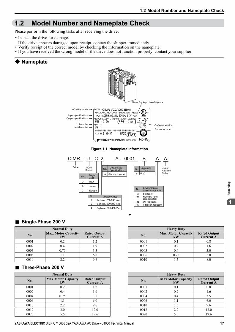
1.2 Model Number and Nameplate CheckPlease perform the following tasks after receiving the drive:• Inspect the drive for damage.
If the drive appears damaged upon receipt, contact the shipper immediately.• Verify receipt of the correct model by checking the information on the nameplate.• If you have received the wrong model or the drive does not function properly, contact your supplier.
u Nameplate
CIMR-VC2A0003BAA
AC3PH 200-240V 50/60Hz 2.7A/1.4AAC3PH 0-240V 0-400Hz 1.2A/0.8A
1010
MADE IN JAPAN
RoHSRoHSPASS
MAX APPLI.MOTOR:0.75kW/0.4kW REV:AAC drive model
Input specificationsOutput specifications
Lot numberSerial number
Software version
Normal Duty Amps / Heavy Duty Amps
Enclosure type
Figure 1.1 Nameplate Information
CIMR - J C 2 A 0001 B A A
No.
Drive J1000 Series
Design Revision Order
No. CustomizedSpecifications
A Standard model
No. Enclosure Type
IP20BNo. Region
CodeU USA
A Japan
C Europe
Voltage ClassB 1-phase, 200-240 Vac
3-phase, 380-480 Vac
3-phase, 200-240 Vac 2
4
No. Environmental Specification <1>
AM
NS
StandardHumidity- and dust-resistantOil-resistant Vibration-resistant
n Single-Phase 200 VNormal Duty Heavy Duty
No. Max. Motor CapacitykW
Rated OutputCurrent A No. Max. Motor Capacity
kWRated Output
Current A0001 0.2 1.2 0001 0.1 0.80002 0.4 1.9 0002 0.2 1.60003 0.75 3.3 0003 0.4 3.00006 1.1 6.0 0006 0.75 5.00010 2.2 9.6 0010 1.5 8.0
n Three-Phase 200 VNormal Duty Heavy Duty
No. Max Motor CapacitykW
Rated OutputCurrent A No. Max Motor Capacity
kWRated Output
Current A0001 0.2 1.2 0001 0.1 0.80002 0.4 1.9 0002 0.2 1.60004 0.75 3.5 0004 0.4 3.50006 1.1 6.0 0006 1.1 6.00010 2.2 9.6 0010 1.5 9.60012 3.0 12.0 0012 2.2 12.00020 5.5 19.6 0020 5.5 19.6
1.2 Model Number and Nameplate Check
YASKAWA ELECTRIC SIEP C710606 32A YASKAWA AC Drive – J1000 Technical Manual 17
1
Rec
eivi
ng
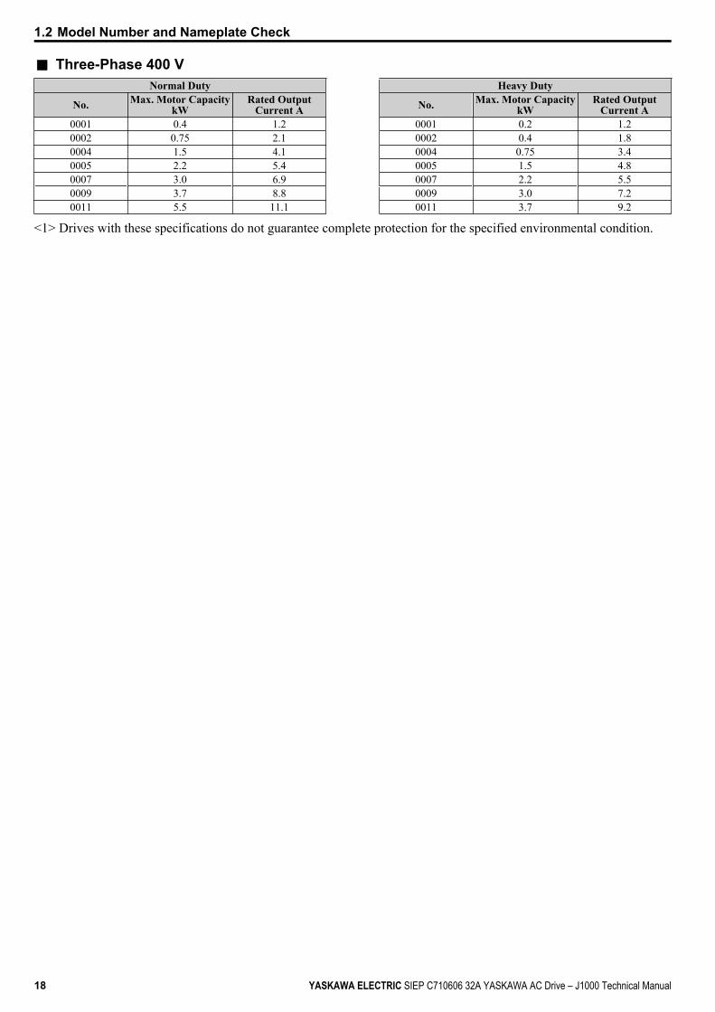
n Three-Phase 400 VNormal Duty Heavy Duty
No. Max. Motor CapacitykW
Rated OutputCurrent A No. Max. Motor Capacity
kWRated Output
Current A0001 0.4 1.2 0001 0.2 1.20002 0.75 2.1 0002 0.4 1.80004 1.5 4.1 0004 0.75 3.40005 2.2 5.4 0005 1.5 4.80007 3.0 6.9 0007 2.2 5.50009 3.7 8.8 0009 3.0 7.20011 5.5 11.1 0011 3.7 9.2
<1> Drives with these specifications do not guarantee complete protection for the specified environmental condition.
1.2 Model Number and Nameplate Check
18 YASKAWA ELECTRIC SIEP C710606 32A YASKAWA AC Drive – J1000 Technical Manual

1.3 Component NamesThis section illustrates the drive components as they are mentioned in this manual.
u IP20/Open-Chassisn Single-Phase AC200 V CIMR-JoBA0001B ~ 0003B
Three-Phase AC200 V CIMR-Jo2A0001B ~ 0006B
K
A
B
C
DE
G
H
J
I
F
A – Mounting holeB – HeatsinkC – Cable coverD – Terminal coverE – Front cover screwF – Option connector cover
G – Front coverH – LED operator Refer to Using the Digital LED
Operator on page 54I – CaseJ – Cooling fan <1>
K – Fan cover <1>
Figure 1.2 Exploded View of IP20/Open-Chassis Type ComponentsThree-Phase AC200 V CIMR-Jo2A0006B
<1> The drives CIMR-JoBA0001B ~ 0003B and CIMR-Jo2A0001B ~ 0004B do not have a cooling fan or a cooling fan cover.
1.3 Component Names
YASKAWA ELECTRIC SIEP C710606 32A YASKAWA AC Drive – J1000 Technical Manual 19
1
Rec
eivi
ng
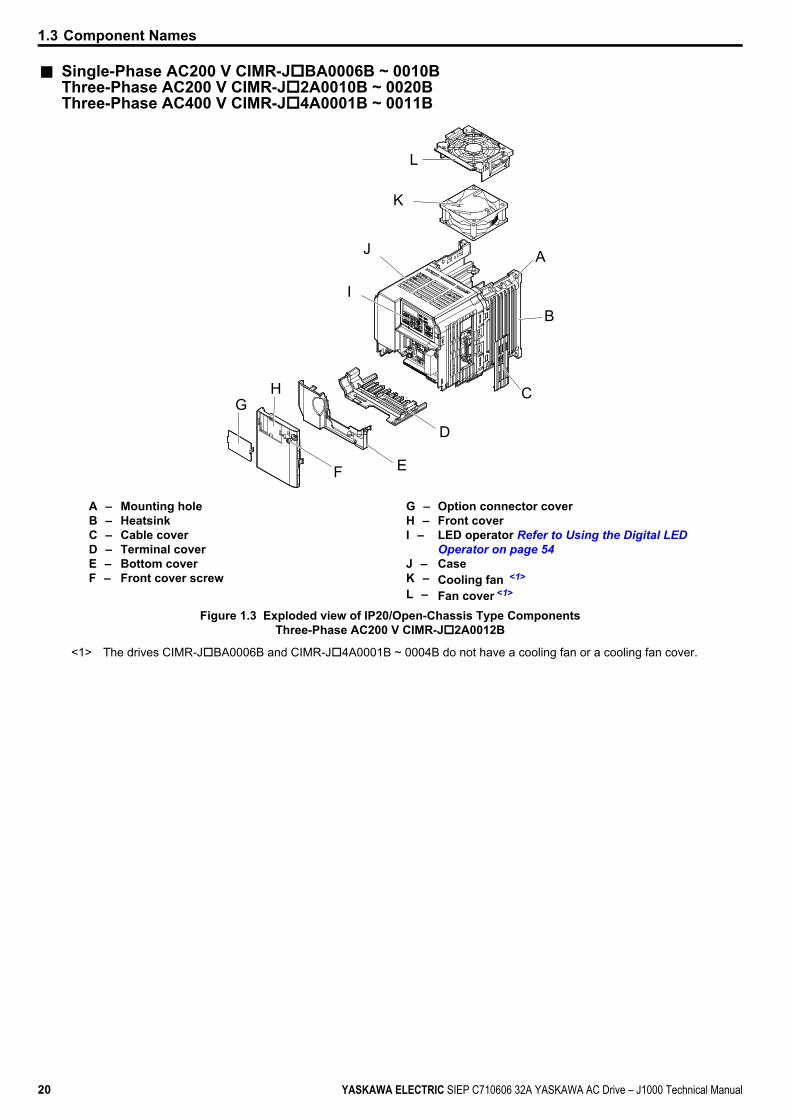
n Single-Phase AC200 V CIMR-JoBA0006B ~ 0010BThree-Phase AC200 V CIMR-Jo2A0010B ~ 0020BThree-Phase AC400 V CIMR-Jo4A0001B ~ 0011B
L
A
B
C
D
F
K
J
I
E
GH
A – Mounting holeB – HeatsinkC – Cable coverD – Terminal coverE – Bottom coverF – Front cover screw
G – Option connector coverH – Front coverI – LED operator Refer to Using the Digital LED
Operator on page 54J – CaseK – Cooling fan <1>
L – Fan cover <1>
Figure 1.3 Exploded view of IP20/Open-Chassis Type ComponentsThree-Phase AC200 V CIMR-Jo2A0012B
<1> The drives CIMR-JoBA0006B and CIMR-Jo4A0001B ~ 0004B do not have a cooling fan or a cooling fan cover.
1.3 Component Names
20 YASKAWA ELECTRIC SIEP C710606 32A YASKAWA AC Drive – J1000 Technical Manual
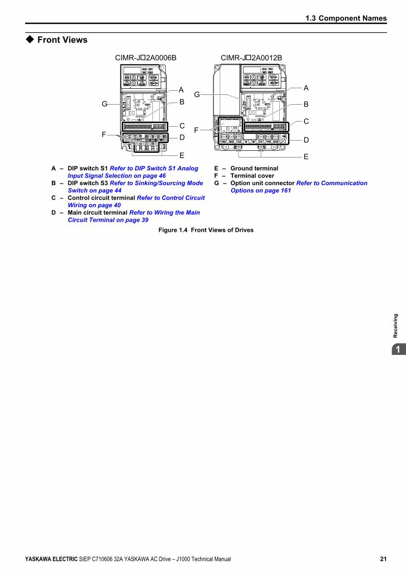
u Front Views
G
F
AB
CD
E
A
B
C
D
E
F
G
CIMR-J 2A0006B CIMR-J 2A0012B
A – DIP switch S1 Refer to DIP Switch S1 Analog Input Signal Selection on page 46
B – DIP switch S3 Refer to Sinking/Sourcing Mode Switch on page 44
C – Control circuit terminal Refer to Control Circuit Wiring on page 40
D – Main circuit terminal Refer to Wiring the Main Circuit Terminal on page 39
E – Ground terminalF – Terminal coverG – Option unit connector Refer to Communication
Options on page 161
Figure 1.4 Front Views of Drives
1.3 Component Names
YASKAWA ELECTRIC SIEP C710606 32A YASKAWA AC Drive – J1000 Technical Manual 21
1
Rec
eivi
ng

1.3 Component Names
This Page Intentionally Blank
22 YASKAWA ELECTRIC SIEP C710606 32A YASKAWA AC Drive – J1000 Technical Manual
Mechanical InstallationThis chapter explains how to properly mount and install the drive.
2.1 SECTION SAFETY............................................................................................242.2 MECHANICAL INSTALLATION.......................................................................26
2
YASKAWA ELECTRIC SIEP C710606 32A YASKAWA AC Drive – J1000 Technical Manual 23
2.1 Section Safety WARNING
Fire HazardProvide sufficient cooling when installing the drive inside an enclosed panel or cabinet.Failure to comply could result in overheating and fire.When multiple drives are placed inside the same enclosure panel, install proper cooling to ensure air entering the enclosuredoes not exceed 40 °C.
CAUTIONCrush Hazard
Do not carry the drive by the front cover.Failure to comply may result in minor or moderate injury from the main body of the drive falling.
NOTICEObserve proper electrostatic discharge (ESD) procedures when handling the drive.Failure to comply could result in ESD damage to the drive circuitry.It may be difficult to perform maintenance on the cooling fans of drives installed in a vertical row inside anenclosure.Ensure adequate spacing at the top of the drive to perform cooling fan replacement when required.Operating the motor in the low-speed range diminishes the cooling effects, increases motor temperature, and maylead to motor damage by overheating.Reduce the motor torque in the low-speed range whenever using a standard blower cooled motor. If 100% torque isrequired continuously at low speed, consider using a special drive or vector motor. Select a motor that is compatible withthe required load torque and operating speed range.Do not operate motors above the maximum rated RPM.Failure to comply may lead to bearing or other mechanical motor failures.The speed range for continuous operation differs according to the lubrication method and motor manufacturer.If the motor is to be operated at a speed higher than the rated speed, consult with the manufacturer.Continuously operating an oil-lubricated motor in the low-speed range may result in burning.
2.1 Section Safety
24 YASKAWA ELECTRIC SIEP C710606 32A YASKAWA AC Drive – J1000 Technical Manual
NOTICEWhen the input voltage is 440 V or higher or the wiring distance is greater than 100 meters, pay special attentionto the motor insulation voltage or use a drive-rated motor.Failure to comply could lead to motor winding failure.Motor vibration may increase when operating a machine in variable-speed mode, if that machine previouslyoperated at a constant speed.Install vibration-proof rubber on the motor base or use the frequency jump function to skip a frequency resonating themachine.The motor may require more acceleration torque with drive operation than with a commercial power supply.Set a proper V/f pattern by checking the load torque characteristics of the machine to be used with the motor.The rated input current of submersible motors is higher than the rated input current of standard motors.Select an appropriate drive according to its rated output current. When the distance between the motor and drive is long,use a cable thick enough to connect the motor to the drive to prevent motor torque reduction.When using an explosion-proof motor, it must be subject to an explosion-proof test in conjunction with the drive.This is also applicable when an existing explosion-proof motor is to be operated with the drive. Since the drive itself isnot explosion-proof, always install it in a safe place.Do not use a drive for a single-phase motor.Replace the motor with a three-phase motor.If an oil-lubricated gearbox or speed reducer is used in the power transmission mechanism, oil lubrication will beaffected when the motor operates only in the low speed range.The power transmission mechanism will make noise and experience problems with service life and durability if the motoris operated at a speed higher than the rated speed.
2.1 Section Safety
YASKAWA ELECTRIC SIEP C710606 32A YASKAWA AC Drive – J1000 Technical Manual 25
2
Mec
hani
cal I
nsta
llatio
n

2.2 Mechanical InstallationThis section outlines specifications, procedures, and environment for proper mechanical installation of the drive.
u Installation EnvironmentTo help prolong the optimum performance life of the drive, install the drive in the proper environment. The table belowprovides a description of the appropriate environment for the drive.
Table 2.1 Installation EnvironmentEnvironment Conditions
Installation Area Indoors
Ambient Temperature
-10 °C to +50 °C (IP20/Open-Chassis)Drive reliability improves in environments without wide temperature fluctuations.When using an enclosure panel, install a cooling fan or air conditioner in the area to ensure that the air temperatureinside the enclosure does not exceed the specified levels.Do not allow ice to develop on the drive.
Humidity 95% RH or less and free of condensationStorage Temperature -20 °C to +60 °C
Surrounding Area
Install the drive in an area free from:• oil mist and dust• metal shavings, oil, water or other foreign materials• radioactive materials• combustible materials (e.g., wood)• harmful gases and liquids• excessive vibration• chlorides• direct sunlight
Altitude 1000 m or lower
Vibration 10 to 20 Hz at 9.8 m/s2
20 to 55 Hz at 5.9 m/s2
Orientation Install the drive vertically to maintain maximum cooling effects.
NOTICE: Prevent foreign matter such as metal shavings or wire clippings from falling into the drive during installation and projectconstruction. Failure to comply could result in damage to the drive. Place a temporary cover over the top of the drive during installation.Remove the temporary cover before startup, as the cover will reduce ventilation and cause the drive to overheat.
2.2 Mechanical Installation
26 YASKAWA ELECTRIC SIEP C710606 32A YASKAWA AC Drive – J1000 Technical Manual
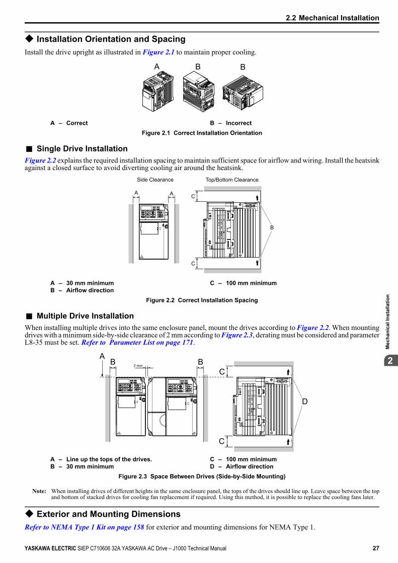
u Installation Orientation and SpacingInstall the drive upright as illustrated in Figure 2.1 to maintain proper cooling.
A B B
A – Correct B – IncorrectFigure 2.1 Correct Installation Orientation
n Single Drive InstallationFigure 2.2 explains the required installation spacing to maintain sufficient space for airflow and wiring. Install the heatsinkagainst a closed surface to avoid diverting cooling air around the heatsink.
A A C
C
B
Side Clearance Top/Bottom Clearance
A – 30 mm minimumB – Airflow direction
C – 100 mm minimum
Figure 2.2 Correct Installation Spacing
n Multiple Drive InstallationWhen installing multiple drives into the same enclosure panel, mount the drives according to Figure 2.2. When mountingdrives with a minimum side-by-side clearance of 2 mm according to Figure 2.3, derating must be considered and parameterL8-35 must be set. Refer to Parameter List on page 171.
2 mm
D
C
CBB
A
A – Line up the tops of the drives.B – 30 mm minimum
C – 100 mm minimumD – Airflow direction
Figure 2.3 Space Between Drives (Side-by-Side Mounting)
Note: When installing drives of different heights in the same enclosure panel, the tops of the drives should line up. Leave space between the topand bottom of stacked drives for cooling fan replacement if required. Using this method, it is possible to replace the cooling fans later.
u Exterior and Mounting DimensionsRefer to NEMA Type 1 Kit on page 158 for exterior and mounting dimensions for NEMA Type 1.
2.2 Mechanical Installation
YASKAWA ELECTRIC SIEP C710606 32A YASKAWA AC Drive – J1000 Technical Manual 27
2
Mec
hani
cal I
nsta
llatio
n
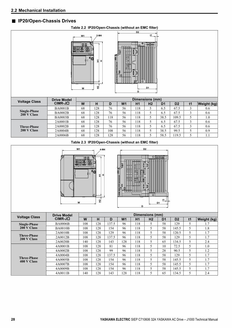
n IP20/Open-Chassis DrivesTable 2.2 IP20/Open-Chassis (without an EMC filter)
t1
D1D
W
H1
H2
H
2-M4W1D2
Voltage Class Drive ModelCIMR-Jo
Dimensions (mm)W H D W1 H1 H2 D1 D2 t1 Weight (kg)
Single-Phase200 V Class
BA0001B 68 128 76 56 118 5 6.5 67.5 3 0.6BA0002B 68 128 76 56 118 5 6.5 67.5 3 0.6BA0003B 68 128 118 56 118 5 38.5 109.5 5 1.0
Three-Phase200 V Class
2A0001B 68 128 76 56 118 5 6.5 67.5 3 0.62A0002B 68 128 76 56 118 5 6.5 67.5 3 0.62A0004B 68 128 108 56 118 5 38.5 99.5 5 0.92A0006B 68 128 128 56 118 5 58.5 119.5 5 1.1
Table 2.3 IP20/Open-Chassis (without an EMC filter)
t1
DD1
4-M4
H
W1
W H2
H1
D2
Voltage Class Drive ModelCIMR-Jo
Dimensions (mm)W H D W1 H1 H2 D1 D2 t1 Weight (kg)
Single-Phase200 V Class
BA0006B 108 128 137.5 96 118 5 58 129 5 1.7BA0010B 108 128 154 96 118 5 58 145.5 5 1.8
Three-Phase200 V Class
2A0010B 108 128 129 96 118 5 58 120.5 5 1.72A0012B 108 128 137.5 96 118 5 58 129 5 1.72A0020B 140 128 143 128 118 5 65 134.5 5 2.4
Three-Phase400 V Class
4A0001B 108 128 81 96 118 5 10 72.5 5 1.04A0002B 108 128 99 96 118 5 28 90.5 5 1.24A0004B 108 128 137.5 96 118 5 58 129 5 1.74A0005B 108 128 154 96 118 5 58 145.5 5 1.74A0007B 108 128 154 96 118 5 58 145.5 5 1.74A0009B 108 128 154 96 118 5 58 145.5 5 1.74A0011B 140 128 143 128 118 5 65 134.5 5 2.4
2.2 Mechanical Installation
28 YASKAWA ELECTRIC SIEP C710606 32A YASKAWA AC Drive – J1000 Technical Manual
Electrical InstallationThis chapter explains proper procedures for wiring the control circuit terminals, motor and powersupply.
3.1 SECTION SAFETY............................................................................................303.2 STANDARD CONNECTION DIAGRAM...........................................................323.3 MAIN CIRCUIT CONNECTION DIAGRAM.......................................................343.4 TERMINAL BLOCK CONFIGURATION...........................................................353.5 PROTECTIVE COVERS....................................................................................363.6 MAIN CIRCUIT WIRING....................................................................................373.7 CONTROL CIRCUIT WIRING...........................................................................403.8 I/O CONNECTIONS...........................................................................................443.9 MAIN FREQUENCY REFERENCE...................................................................463.10 BRAKING RESISTOR.......................................................................................473.11 INTERLOCKING WITH CONNECTED MACHINERY.......................................483.12 WIRING CHECKLIST........................................................................................49
3
YASKAWA ELECTRIC SIEP C710606 32A YASKAWA AC Drive – J1000 Technical Manual 29

3.1 Section Safety DANGER
Electrical Shock HazardDo not connect or disconnect wiring while the power is on.Failure to comply will result in death or serious injury.
WARNINGElectrical Shock Hazard
Do not operate equipment with covers removed.Failure to comply could result in death or serious injury.The diagrams in this section may show drives without covers or safety shields to show details. Be sure to reinstall coversor shields before operating the drives and run the drives according to the instructions described in this manual.Always ground the motor-side grounding terminal.Improper equipment grounding could result in death or serious injury by contacting the motor case.Do not perform work on the drive while wearing loose clothing, jewelry or without eye protection.Failure to comply could result in death or serious injury.Remove all metal objects such as watches and rings, secure loose clothing, and wear eye protection before beginningwork on the drive.Do not remove covers or touch circuit boards while the power is on.Failure to comply could result in death or serious injury.Do not allow unqualified personnel to perform work on the drive.Failure to comply could result in death or serious injury.Installation, maintenance, inspection, and servicing must be performed only by authorized personnel familiar withinstallation, adjustment, and maintenance of AC drives.Do not touch any terminals before the capacitors have fully discharged.Failure to comply could result in death or serious injury.Before wiring terminals, disconnect all power to the equipment. The internal capacitor remains charged even after thepower supply is turned off. The charge indicator LED will extinguish when the DC bus voltage is below 50 Vdc. Toprevent electric shock, wait at least one minute after all indicators are off and measure the DC bus voltage level to confirmsafe level.
Fire HazardTighten all terminal screws to the specified tightening torque.Loose electrical connections could result in death or serious injury by fire due to overheating of electrical connections.Do not use improper combustible materials.Failure to comply could result in death or serious injury by fire.Attach the drive to metal or other noncombustible material.Do not use an improper voltage source.Failure to comply could result in death or serious injury by fire.Verify that the rated voltage of the drive matches the voltage of the incoming power supply before applying power.
3.1 Section Safety
30 YASKAWA ELECTRIC SIEP C710606 32A YASKAWA AC Drive – J1000 Technical Manual
NOTICEObserve proper electrostatic discharge procedures (ESD) when handling the drive and circuit boards.Failure to comply may result in ESD damage to the drive circuitry.Never connect or disconnect the motor from the drive while the drive is outputting voltage.Improper equipment sequencing could result in damage to the drive.Do not use unshielded cable for control wiring.Failure to comply may cause electrical interference resulting in poor system performance. Use shielded, twisted-pairwires and ground the shield to the ground terminal of the drive.Check all the wiring to ensure that all connections are correct after installing the drive and connecting any otherdevices.Failure to comply could result in damage to the drive.Do not modify the drive circuitry.Failure to comply could result in damage to the drive and will void warranty.Yaskawa is not responsible for any modification of the product made by the user. This product must not be modified.
3.1 Section Safety
YASKAWA ELECTRIC SIEP C710606 32A YASKAWA AC Drive – J1000 Technical Manual 31
3El
ectr
ical
Inst
alla
tion

3.2 Standard Connection DiagramConnect the drive and peripheral devices as shown in Figure 3.1. It is possible to run the drive via the digital operatorwithout connecting digital I/O wiring. This section does not discuss drive operation; Refer to Start-Up Programming & Operation on page 51 for instructions on operating the drive.NOTICE: Inadequate branch short circuit protection could result in damage to the drive. Install adequate branch circuit short circuitprotection per applicable codes. The drive is suitable for circuits capable of delivering not more than 30,000 RMS symmetrical amperes,240 Vac maximum (200 V Class) and 480 Vac maximum (400 V Class).NOTICE: When the input voltage is 440 V or higher or the wiring distance is greater than 100 meters, pay special attention to the motorinsulation voltage or use a drive duty motor. Failure to comply could lead to motor insulation breakdown.NOTICE: Do not connect AC control circuit ground to drive enclosure. Improper drive grounding can cause control circuit malfunction.NOTICE: The minimum load for the multi-function relay output MA-MB-MC is 10 mA.
SA
MotorCooling fan
Forward run/stop
Reverse run/stop
External fault
Fault reset
0 to +10 Vdc (2 mA)
DIPswitch S3
DC reactor(option)
Digital inputs(default setting)
Fault
J1000
Shield groundterminal
Thermal relay(option) Braking resistor
(option)
Main circuit
Control circuit
Thermal relay formotor cooling fan
Fault relay
1 MCCB MC
2 MCCBr1s1
t1
R/L1
S/L2
T/L3
S1
S2
S3
S4
S5
<3><1> <2>
- B1+1+2 B2
R/L1S/L2
T/L3
MCTHRX
TRX
MCTRX
MC MA
U/T1
V/T2
W/T3
24
V
MA
MB
MC
I V
+24 V 8 mA
M
M
r1
s1
t1
FU
FVFW
U
V
W
SC
AM
AC
+
-
AM
+V
A1
AC
2 k
Ground10 or less (400 V class)100 or less (200 V class)
Setting power supply+10.5 max. 20 mA
For single phase 200 Vpower supply, useR/L1 and S/L2.
Analog monitoroutput
Digital output250 Vac, 10 mA to 1 A30 Vdc, 10 mA to 1 A(default setting)
Main speedfrequencyreference.Multi-functionprogrammable
Multi-step speed 1 main/aux switch
2 MCCB THRX OFF ON MC
SA
SA
Three phasepower supply200 to 240 V
Jumper
DIP switch S1
Sink
Source
Terminals +1, +2, , B1, and B2are for connecting options.Never connect power supplylines to these terminals.
_
Monitoroutput
Option unitconnector
main circuit terminal
shielded line twisted-pair shielded line
control terminal
<4>
<5>
<6>
<7>0 to +10 V (20 k )(0)4 to 20 mA (250 )
Figure 3.1 Drive Standard Connection Diagram (200 V Class Example)
<1> Remove the jumper when installing an optional DC reactor.<2> The MC on the input side of the main circuit should open when the thermal relay is triggered.<3> Self-cooled motors do not require separate cooling fan motor wiring.<4> Connected using sequence input signal (S1 to S5) from NPN transistor; Default: sink mode (0 V com).<5> Use only a +24 V internal power supply in sinking mode; the source mode requires an external power supply Refer
to I/O Connections on page 44.<6> Minimum load: 5 Vdc, 10 mA (reference value).
3.2 Standard Connection Diagram
32 YASKAWA ELECTRIC SIEP C710606 32A YASKAWA AC Drive – J1000 Technical Manual
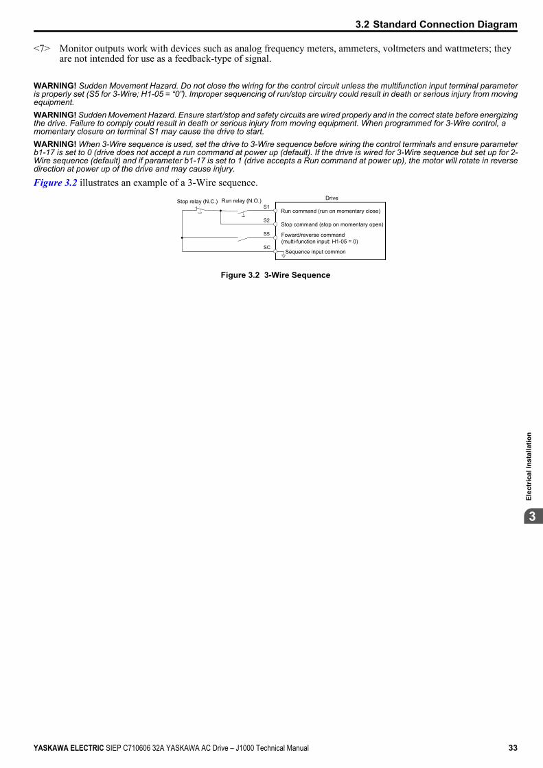
<7> Monitor outputs work with devices such as analog frequency meters, ammeters, voltmeters and wattmeters; theyare not intended for use as a feedback-type of signal.
WARNING! Sudden Movement Hazard. Do not close the wiring for the control circuit unless the multifunction input terminal parameteris properly set (S5 for 3-Wire; H1-05 = “0”). Improper sequencing of run/stop circuitry could result in death or serious injury from movingequipment.WARNING! Sudden Movement Hazard. Ensure start/stop and safety circuits are wired properly and in the correct state before energizingthe drive. Failure to comply could result in death or serious injury from moving equipment. When programmed for 3-Wire control, amomentary closure on terminal S1 may cause the drive to start.WARNING! When 3-Wire sequence is used, set the drive to 3-Wire sequence before wiring the control terminals and ensure parameterb1-17 is set to 0 (drive does not accept a run command at power up (default). If the drive is wired for 3-Wire sequence but set up for 2-Wire sequence (default) and if parameter b1-17 is set to 1 (drive accepts a Run command at power up), the motor will rotate in reversedirection at power up of the drive and may cause injury.
Figure 3.2 illustrates an example of a 3-Wire sequence.Drive
Sequence input common
Run relay (N.O.)Stop relay (N.C.)
Run command (run on momentary close)
Stop command (stop on momentary open)
Foward/reverse command (multi-function input: H1-05 = 0)
S1
S2
S5
SC
Figure 3.2 3-Wire Sequence
3.2 Standard Connection Diagram
YASKAWA ELECTRIC SIEP C710606 32A YASKAWA AC Drive – J1000 Technical Manual 33
3El
ectr
ical
Inst
alla
tion
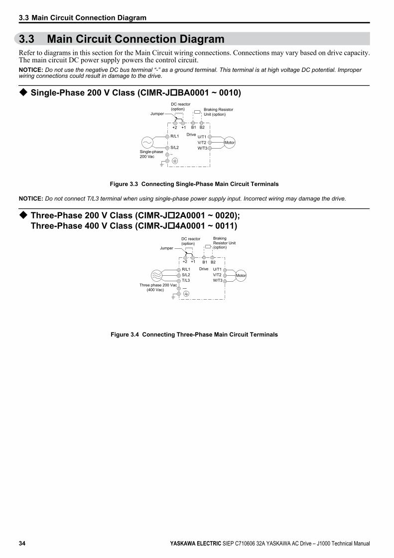
3.3 Main Circuit Connection DiagramRefer to diagrams in this section for the Main Circuit wiring connections. Connections may vary based on drive capacity.The main circuit DC power supply powers the control circuit.NOTICE: Do not use the negative DC bus terminal “-” as a ground terminal. This terminal is at high voltage DC potential. Improperwiring connections could result in damage to the drive.
u Single-Phase 200 V Class (CIMR-JoBA0001 ~ 0010)
Drive
Jumper
Single-phase 200 Vac
Motor
DC reactor(option) Braking Resistor
Unit (option)
R/L1
S/L2
+1+2
–
B1 B2
U/T1V/T2W/T3
Figure 3.3 Connecting Single-Phase Main Circuit Terminals
NOTICE: Do not connect T/L3 terminal when using single-phase power supply input. Incorrect wiring may damage the drive.
u Three-Phase 200 V Class (CIMR-Jo2A0001 ~ 0020);Three-Phase 400 V Class (CIMR-Jo4A0001 ~ 0011)
—
Drive
Motor
Three phase 200 Vac (400 Vac)
Braking Resistor Unit(option)
R/L1S/L2T/L3
U/T1V/T2W/T3
B1 B2
Jumper
DC reactor(option)
+1+2
Figure 3.4 Connecting Three-Phase Main Circuit Terminals
3.3 Main Circuit Connection Diagram
34 YASKAWA ELECTRIC SIEP C710606 32A YASKAWA AC Drive – J1000 Technical Manual
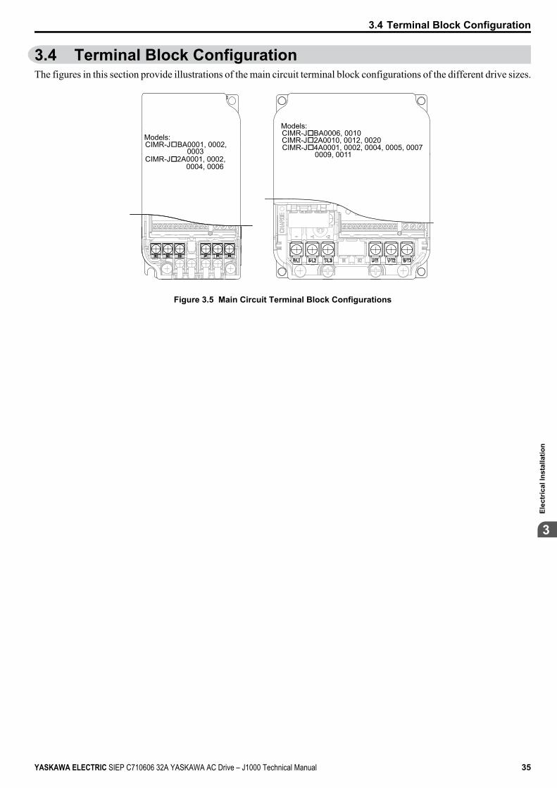
3.4 Terminal Block ConfigurationThe figures in this section provide illustrations of the main circuit terminal block configurations of the different drive sizes.
Models:CIMR-J BA0001, 0002,
CIMR-J 2A0001, 0002,
Models:CIMR-J BA0006, 0010CIMR-J 2A0010, 0012, 0020CIMR-J 4A0001, 0002, 0004, 0005, 0007
0009, 0011 0004, 0006
0003
Figure 3.5 Main Circuit Terminal Block Configurations
3.4 Terminal Block Configuration
YASKAWA ELECTRIC SIEP C710606 32A YASKAWA AC Drive – J1000 Technical Manual 35
3El
ectr
ical
Inst
alla
tion
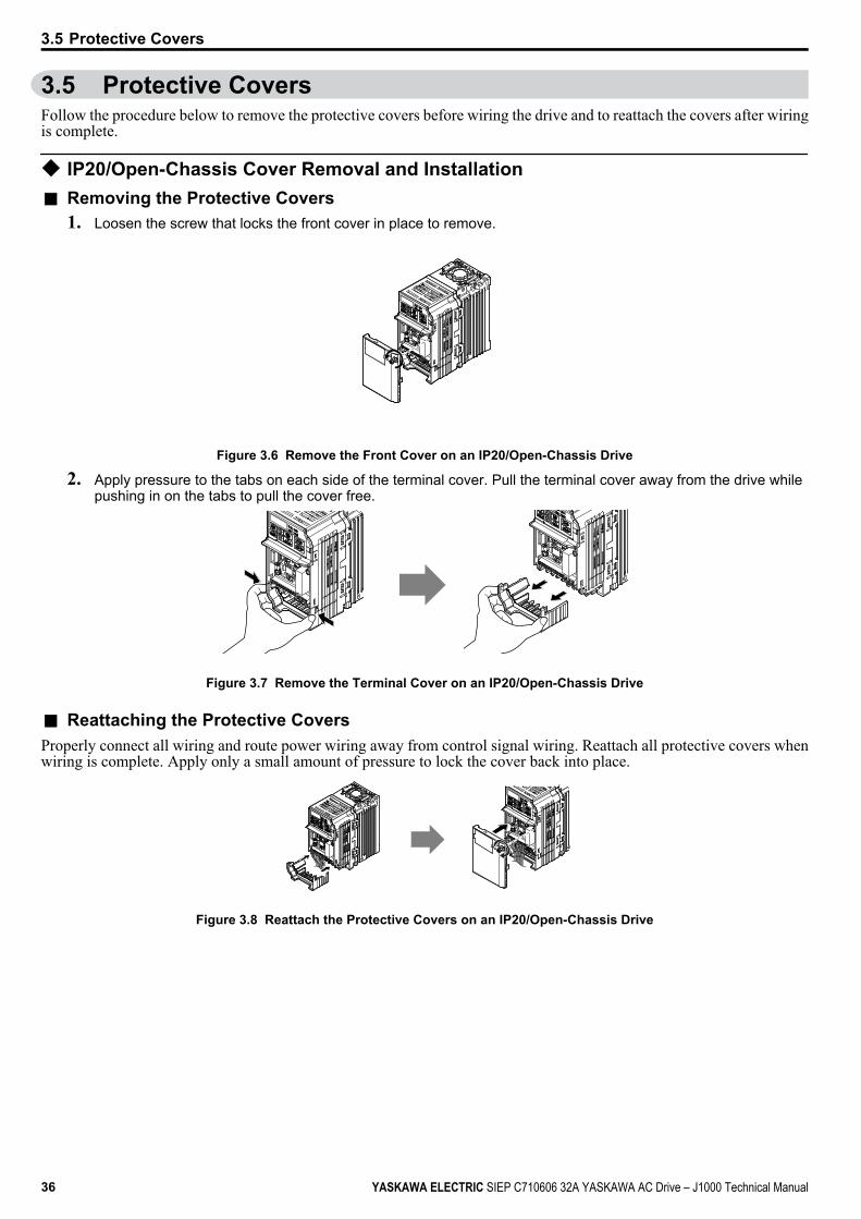
3.5 Protective CoversFollow the procedure below to remove the protective covers before wiring the drive and to reattach the covers after wiringis complete.
u IP20/Open-Chassis Cover Removal and Installationn Removing the Protective Covers
1. Loosen the screw that locks the front cover in place to remove.
Figure 3.6 Remove the Front Cover on an IP20/Open-Chassis Drive
2. Apply pressure to the tabs on each side of the terminal cover. Pull the terminal cover away from the drive whilepushing in on the tabs to pull the cover free.
Figure 3.7 Remove the Terminal Cover on an IP20/Open-Chassis Drive
n Reattaching the Protective CoversProperly connect all wiring and route power wiring away from control signal wiring. Reattach all protective covers whenwiring is complete. Apply only a small amount of pressure to lock the cover back into place.
Figure 3.8 Reattach the Protective Covers on an IP20/Open-Chassis Drive
3.5 Protective Covers
36 YASKAWA ELECTRIC SIEP C710606 32A YASKAWA AC Drive – J1000 Technical Manual
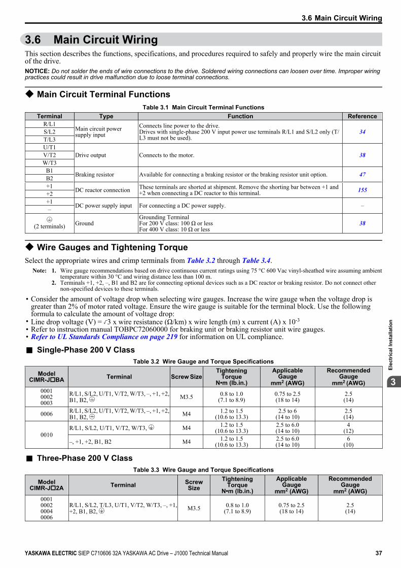
3.6 Main Circuit WiringThis section describes the functions, specifications, and procedures required to safely and properly wire the main circuitof the drive.NOTICE: Do not solder the ends of wire connections to the drive. Soldered wiring connections can loosen over time. Improper wiringpractices could result in drive malfunction due to loose terminal connections.
u Main Circuit Terminal FunctionsTable 3.1 Main Circuit Terminal Functions
Terminal Type Function ReferenceR/L1
Main circuit powersupply input
Connects line power to the drive.Drives with single-phase 200 V input power use terminals R/L1 and S/L2 only (T/L3 must not be used).
34S/L2T/L3U/T1
Drive output Connects to the motor. 38V/T2W/T3
B1 Braking resistor Available for connecting a braking resistor or the braking resistor unit option. 47B2+1 DC reactor connection These terminals are shorted at shipment. Remove the shorting bar between +1 and
+2 when connecting a DC reactor to this terminal. 155+2+1 DC power supply input For connecting a DC power supply. ––
(2 terminals) GroundGrounding TerminalFor 200 V class: 100 Ω or lessFor 400 V class: 10 Ω or less
38
u Wire Gauges and Tightening TorqueSelect the appropriate wires and crimp terminals from Table 3.2 through Table 3.4.
Note: 1. Wire gauge recommendations based on drive continuous current ratings using 75 °C 600 Vac vinyl-sheathed wire assuming ambienttemperature within 30 °C and wiring distance less than 100 m.
2. Terminals +1, +2, –, B1 and B2 are for connecting optional devices such as a DC reactor or braking resistor. Do not connect othernon-specified devices to these terminals.
• Consider the amount of voltage drop when selecting wire gauges. Increase the wire gauge when the voltage drop isgreater than 2% of motor rated voltage. Ensure the wire gauge is suitable for the terminal block. Use the followingformula to calculate the amount of voltage drop:
• Line drop voltage (V) = 3 x wire resistance (Ω/km) x wire length (m) x current (A) x 10-3
• Refer to instruction manual TOBPC72060000 for braking unit or braking resistor unit wire gauges.• Refer to UL Standards Compliance on page 219 for information on UL compliance.
n Single-Phase 200 V ClassTable 3.2 Wire Gauge and Torque Specifications
ModelCIMR-JoBA Terminal Screw Size
TighteningTorque
N•m (lb.in.)
ApplicableGauge
mm2 (AWG)
RecommendedGauge
mm2 (AWG)000100020003
R/L1, S/L2, U/T1, V/T2, W/T3, –, +1, +2,B1, B2, M3.5 0.8 to 1.0
(7.1 to 8.9)0.75 to 2.5(18 to 14)
2.5(14)
0006 R/L1, S/L2, U/T1, V/T2, W/T3, –, +1, +2,B1, B2, M4 1.2 to 1.5
(10.6 to 13.3)2.5 to 6
(14 to 10)2.5(14)
0010R/L1, S/L2, U/T1, V/T2, W/T3, M4 1.2 to 1.5
(10.6 to 13.3)2.5 to 6.0(14 to 10)
4(12)
–, +1, +2, B1, B2 M4 1.2 to 1.5(10.6 to 13.3)
2.5 to 6.0(14 to 10)
6(10)
n Three-Phase 200 V ClassTable 3.3 Wire Gauge and Torque Specifications
ModelCIMR-Jo2A Terminal Screw
SizeTightening
TorqueN•m (lb.in.)
ApplicableGauge
mm2 (AWG)
RecommendedGauge
mm2 (AWG)0001000200040006
R/L1, S/L2, T/L3, U/T1, V/T2, W/T3, –, +1,+2, B1, B2, M3.5 0.8 to 1.0
(7.1 to 8.9)0.75 to 2.5(18 to 14)
2.5(14)
3.6 Main Circuit Wiring
YASKAWA ELECTRIC SIEP C710606 32A YASKAWA AC Drive – J1000 Technical Manual 37
3El
ectr
ical
Inst
alla
tion
ModelCIMR-Jo2A Terminal Screw
SizeTightening
TorqueN•m (lb.in.)
ApplicableGauge
mm2 (AWG)
RecommendedGauge
mm2 (AWG)
0010R/L1, S/L2, T/L3, U/T1, V/T2, W/T3, –, +1,+2, B1, B2 M4 1.2 to 1.5
(10.6 to 13.3)2.5 to 6
(14 to 10)2.5(14)
M4 1.2 to 1.5(10.6 to 13.3)
2.5 to 6(14 to 10)
4(12)
0012 R/L1, S/L2, T/L3, U/T1, V/T2, W/T3, –, +1,+2, B1, B2, M4 1.2 to 1.5
(10.6 to 13.3)2.5 to 6
(14 to 10)4
(12)
0020 R/L1, S/L2, T/L3, U/T1, V/T2, W/T3, –, +1,+2, B1, B2, M4 1.2 to 1.5
(10.6 to 13.3)2.5 to 6
(14 to 10)6
(10)
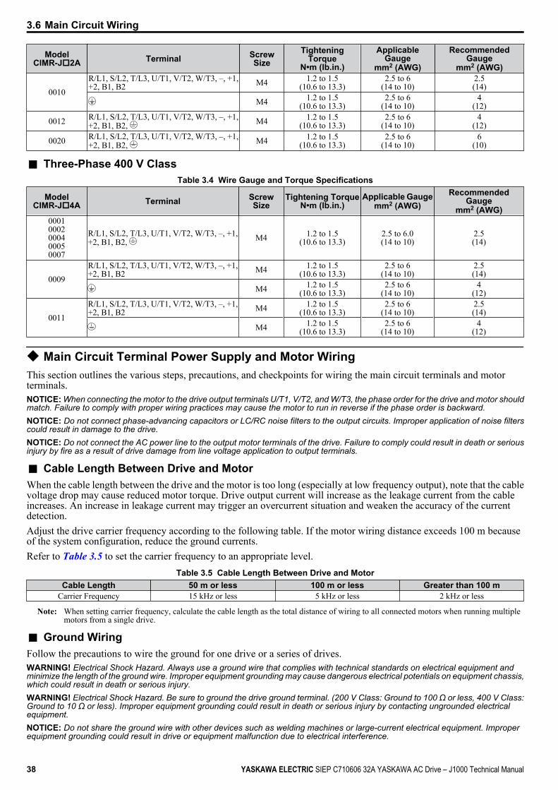
n Three-Phase 400 V ClassTable 3.4 Wire Gauge and Torque Specifications
ModelCIMR-Jo4A Terminal Screw
SizeTightening Torque
N•m (lb.in.)Applicable Gauge
mm2 (AWG)Recommended
Gaugemm2 (AWG)
00010002000400050007
R/L1, S/L2, T/L3, U/T1, V/T2, W/T3, –, +1,+2, B1, B2, M4 1.2 to 1.5
(10.6 to 13.3)2.5 to 6.0(14 to 10)
2.5(14)
0009R/L1, S/L2, T/L3, U/T1, V/T2, W/T3, –, +1,+2, B1, B2 M4 1.2 to 1.5
(10.6 to 13.3)2.5 to 6
(14 to 10)2.5(14)
M4 1.2 to 1.5(10.6 to 13.3)
2.5 to 6(14 to 10)
4(12)
0011R/L1, S/L2, T/L3, U/T1, V/T2, W/T3, –, +1,+2, B1, B2 M4 1.2 to 1.5
(10.6 to 13.3)2.5 to 6
(14 to 10)2.5(14)
M4 1.2 to 1.5(10.6 to 13.3)
2.5 to 6(14 to 10)
4(12)
u Main Circuit Terminal Power Supply and Motor WiringThis section outlines the various steps, precautions, and checkpoints for wiring the main circuit terminals and motorterminals.NOTICE: When connecting the motor to the drive output terminals U/T1, V/T2, and W/T3, the phase order for the drive and motor shouldmatch. Failure to comply with proper wiring practices may cause the motor to run in reverse if the phase order is backward.NOTICE: Do not connect phase-advancing capacitors or LC/RC noise filters to the output circuits. Improper application of noise filterscould result in damage to the drive.NOTICE: Do not connect the AC power line to the output motor terminals of the drive. Failure to comply could result in death or seriousinjury by fire as a result of drive damage from line voltage application to output terminals.
n Cable Length Between Drive and MotorWhen the cable length between the drive and the motor is too long (especially at low frequency output), note that the cablevoltage drop may cause reduced motor torque. Drive output current will increase as the leakage current from the cableincreases. An increase in leakage current may trigger an overcurrent situation and weaken the accuracy of the currentdetection.Adjust the drive carrier frequency according to the following table. If the motor wiring distance exceeds 100 m becauseof the system configuration, reduce the ground currents.Refer to Table 3.5 to set the carrier frequency to an appropriate level.
Table 3.5 Cable Length Between Drive and MotorCable Length 50 m or less 100 m or less Greater than 100 m
Carrier Frequency 15 kHz or less 5 kHz or less 2 kHz or less
Note: When setting carrier frequency, calculate the cable length as the total distance of wiring to all connected motors when running multiplemotors from a single drive.
n Ground WiringFollow the precautions to wire the ground for one drive or a series of drives.WARNING! Electrical Shock Hazard. Always use a ground wire that complies with technical standards on electrical equipment andminimize the length of the ground wire. Improper equipment grounding may cause dangerous electrical potentials on equipment chassis,which could result in death or serious injury.WARNING! Electrical Shock Hazard. Be sure to ground the drive ground terminal. (200 V Class: Ground to 100 Ω or less, 400 V Class:Ground to 10 Ω or less). Improper equipment grounding could result in death or serious injury by contacting ungrounded electricalequipment.NOTICE: Do not share the ground wire with other devices such as welding machines or large-current electrical equipment. Improperequipment grounding could result in drive or equipment malfunction due to electrical interference.
3.6 Main Circuit Wiring
38 YASKAWA ELECTRIC SIEP C710606 32A YASKAWA AC Drive – J1000 Technical Manual
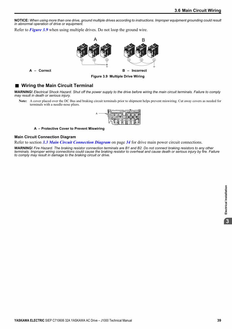
NOTICE: When using more than one drive, ground multiple drives according to instructions. Improper equipment grounding could resultin abnormal operation of drive or equipment.
Refer to Figure 3.9 when using multiple drives. Do not loop the ground wire.
A B
A – Correct B – IncorrectFigure 3.9 Multiple Drive Wiring
n Wiring the Main Circuit TerminalWARNING! Electrical Shock Hazard. Shut off the power supply to the drive before wiring the main circuit terminals. Failure to complymay result in death or serious injury.
Note: A cover placed over the DC Bus and braking circuit terminals prior to shipment helps prevent miswiring. Cut away covers as needed forterminals with a needle-nose pliers.
A
A – Protective Cover to Prevent Miswiring
Main Circuit Connection DiagramRefer to section 3.3 Main Circuit Connection Diagram on page 34 for drive main power circuit connections.WARNING! Fire Hazard. The braking resistor connection terminals are B1 and B2. Do not connect braking resistors to any otherterminals. Improper wiring connections could cause the braking resistor to overheat and cause death or serious injury by fire. Failureto comply may result in damage to the braking circuit or drive.
3.6 Main Circuit Wiring
YASKAWA ELECTRIC SIEP C710606 32A YASKAWA AC Drive – J1000 Technical Manual 39
3El
ectr
ical
Inst
alla
tion
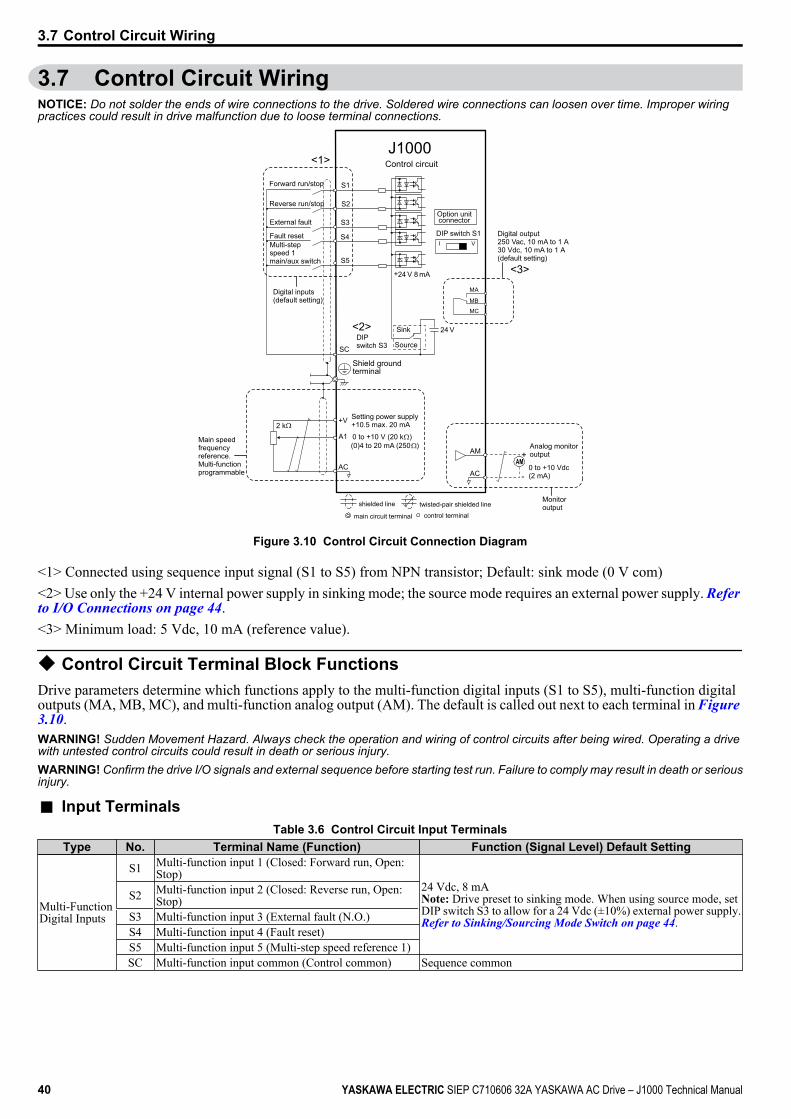
3.7 Control Circuit WiringNOTICE: Do not solder the ends of wire connections to the drive. Soldered wire connections can loosen over time. Improper wiringpractices could result in drive malfunction due to loose terminal connections.
S1
S2
S3
S4
S5
24 V
I V
+24 V 8 mA
SC
AM
AC
+
-
AM
+V
A1
AC
2 k
MA
MB
MC
Forward run/stop
Reverse run/stop
External fault
Fault reset
Digital inputs(default setting)
J1000Control circuit
Multi-step speed 1 main/aux switch
DIP switch S1
Option unitconnector
<1>
DIPswitch S3
Shield groundterminal
0 to +10 V (20 k )(0)4 to 20 mA (250 )
Setting power supply+10.5 max. 20 mA
Digital output250 Vac, 10 mA to 1 A30 Vdc, 10 mA to 1 A(default setting)
Main speedfrequencyreference.Multi-functionprogrammable
Sink
Source
<2>
<3>
0 to +10 Vdc (2 mA)
Analog monitoroutput
Monitoroutput
main circuit terminal
shielded line twisted-pair shielded line
control terminal
Figure 3.10 Control Circuit Connection Diagram
<1> Connected using sequence input signal (S1 to S5) from NPN transistor; Default: sink mode (0 V com)<2> Use only the +24 V internal power supply in sinking mode; the source mode requires an external power supply. Refer to I/O Connections on page 44.<3> Minimum load: 5 Vdc, 10 mA (reference value).
u Control Circuit Terminal Block FunctionsDrive parameters determine which functions apply to the multi-function digital inputs (S1 to S5), multi-function digitaloutputs (MA, MB, MC), and multi-function analog output (AM). The default is called out next to each terminal in Figure 3.10.WARNING! Sudden Movement Hazard. Always check the operation and wiring of control circuits after being wired. Operating a drivewith untested control circuits could result in death or serious injury.WARNING! Confirm the drive I/O signals and external sequence before starting test run. Failure to comply may result in death or seriousinjury.
n Input TerminalsTable 3.6 Control Circuit Input Terminals
Type No. Terminal Name (Function) Function (Signal Level) Default Setting
Multi-FunctionDigital Inputs
S1 Multi-function input 1 (Closed: Forward run, Open:Stop)
24 Vdc, 8 mANote: Drive preset to sinking mode. When using source mode, setDIP switch S3 to allow for a 24 Vdc (±10%) external power supply.Refer to Sinking/Sourcing Mode Switch on page 44.
S2 Multi-function input 2 (Closed: Reverse run, Open:Stop)
S3 Multi-function input 3 (External fault (N.O.)S4 Multi-function input 4 (Fault reset)S5 Multi-function input 5 (Multi-step speed reference 1)SC Multi-function input common (Control common) Sequence common
3.7 Control Circuit Wiring
40 YASKAWA ELECTRIC SIEP C710606 32A YASKAWA AC Drive – J1000 Technical Manual
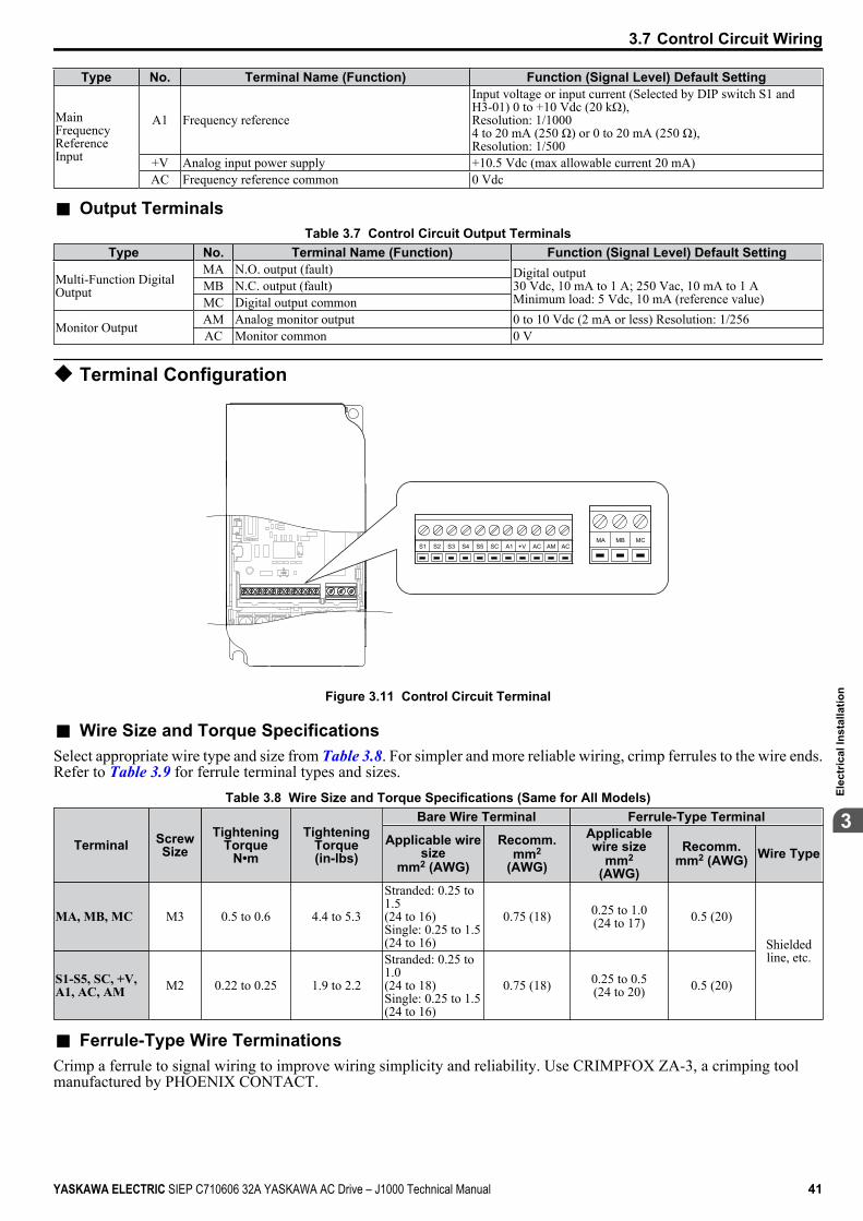
Type No. Terminal Name (Function) Function (Signal Level) Default Setting
MainFrequencyReferenceInput
A1 Frequency reference
Input voltage or input current (Selected by DIP switch S1 andH3-01) 0 to +10 Vdc (20 kΩ),Resolution: 1/10004 to 20 mA (250 Ω) or 0 to 20 mA (250 Ω),Resolution: 1/500
+V Analog input power supply +10.5 Vdc (max allowable current 20 mA)AC Frequency reference common 0 Vdc
n Output TerminalsTable 3.7 Control Circuit Output Terminals
Type No. Terminal Name (Function) Function (Signal Level) Default Setting
Multi-Function DigitalOutput
MA N.O. output (fault) Digital output30 Vdc, 10 mA to 1 A; 250 Vac, 10 mA to 1 AMinimum load: 5 Vdc, 10 mA (reference value)
MB N.C. output (fault)MC Digital output common
Monitor Output AM Analog monitor output 0 to 10 Vdc (2 mA or less) Resolution: 1/256AC Monitor common 0 V
u Terminal Configuration
S1 S2 S3 S4 S5 SC A1 +V AC AM ACMCMBMA
Figure 3.11 Control Circuit Terminal
n Wire Size and Torque SpecificationsSelect appropriate wire type and size from Table 3.8. For simpler and more reliable wiring, crimp ferrules to the wire ends.Refer to Table 3.9 for ferrule terminal types and sizes.
Table 3.8 Wire Size and Torque Specifications (Same for All Models)
Terminal ScrewSize
TighteningTorque
N•m
TighteningTorque(in-lbs)
Bare Wire Terminal Ferrule-Type Terminal
Applicable wiresize
mm2 (AWG)
Recomm.mm2
(AWG)
Applicablewire size
mm2
(AWG)
Recomm.mm2 (AWG) Wire Type
MA, MB, MC M3 0.5 to 0.6 4.4 to 5.3
Stranded: 0.25 to1.5(24 to 16)Single: 0.25 to 1.5(24 to 16)
0.75 (18) 0.25 to 1.0(24 to 17) 0.5 (20)
Shieldedline, etc.
S1-S5, SC, +V,A1, AC, AM M2 0.22 to 0.25 1.9 to 2.2
Stranded: 0.25 to1.0(24 to 18)Single: 0.25 to 1.5(24 to 16)
0.75 (18) 0.25 to 0.5(24 to 20) 0.5 (20)
n Ferrule-Type Wire TerminationsCrimp a ferrule to signal wiring to improve wiring simplicity and reliability. Use CRIMPFOX ZA-3, a crimping toolmanufactured by PHOENIX CONTACT.
3.7 Control Circuit Wiring
YASKAWA ELECTRIC SIEP C710606 32A YASKAWA AC Drive – J1000 Technical Manual 41
3El
ectr
ical
Inst
alla
tion
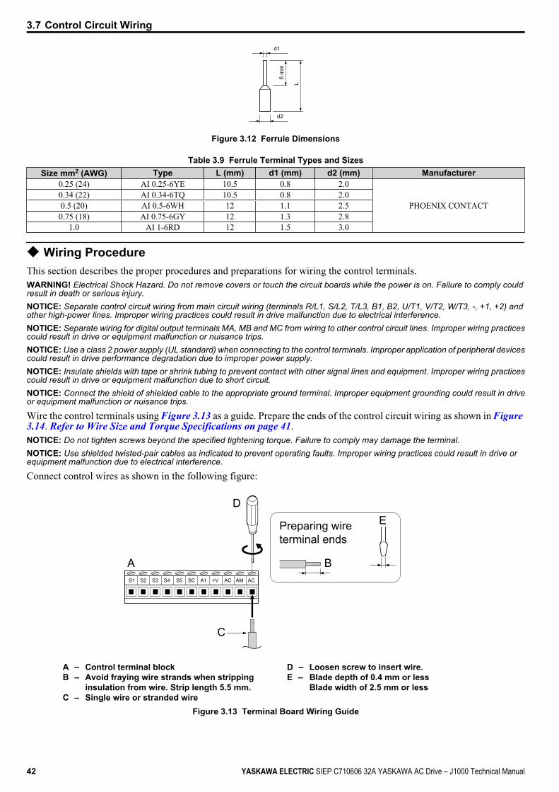
d1
d2
6 m
m
L
Figure 3.12 Ferrule Dimensions
Table 3.9 Ferrule Terminal Types and SizesSize mm2 (AWG) Type L (mm) d1 (mm) d2 (mm) Manufacturer
0.25 (24) AI 0.25-6YE 10.5 0.8 2.0
PHOENIX CONTACT0.34 (22) AI 0.34-6TQ 10.5 0.8 2.00.5 (20) AI 0.5-6WH 12 1.1 2.50.75 (18) AI 0.75-6GY 12 1.3 2.8
1.0 AI 1-6RD 12 1.5 3.0
u Wiring ProcedureThis section describes the proper procedures and preparations for wiring the control terminals.WARNING! Electrical Shock Hazard. Do not remove covers or touch the circuit boards while the power is on. Failure to comply couldresult in death or serious injury.NOTICE: Separate control circuit wiring from main circuit wiring (terminals R/L1, S/L2, T/L3, B1, B2, U/T1, V/T2, W/T3, -, +1, +2) andother high-power lines. Improper wiring practices could result in drive malfunction due to electrical interference.NOTICE: Separate wiring for digital output terminals MA, MB and MC from wiring to other control circuit lines. Improper wiring practicescould result in drive or equipment malfunction or nuisance trips.NOTICE: Use a class 2 power supply (UL standard) when connecting to the control terminals. Improper application of peripheral devicescould result in drive performance degradation due to improper power supply.NOTICE: Insulate shields with tape or shrink tubing to prevent contact with other signal lines and equipment. Improper wiring practicescould result in drive or equipment malfunction due to short circuit.NOTICE: Connect the shield of shielded cable to the appropriate ground terminal. Improper equipment grounding could result in driveor equipment malfunction or nuisance trips.
Wire the control terminals using Figure 3.13 as a guide. Prepare the ends of the control circuit wiring as shown in Figure 3.14. Refer to Wire Size and Torque Specifications on page 41.NOTICE: Do not tighten screws beyond the specified tightening torque. Failure to comply may damage the terminal.NOTICE: Use shielded twisted-pair cables as indicated to prevent operating faults. Improper wiring practices could result in drive orequipment malfunction due to electrical interference.
Connect control wires as shown in the following figure:
S1 S2 S3 S4 S5 SC A1 +V AC AM AC
A
D
C
E
B
Preparing wireterminal ends
A – Control terminal blockB – Avoid fraying wire strands when stripping
insulation from wire. Strip length 5.5 mm.C – Single wire or stranded wire
D – Loosen screw to insert wire.E – Blade depth of 0.4 mm or less
Blade width of 2.5 mm or less
Figure 3.13 Terminal Board Wiring Guide
3.7 Control Circuit Wiring
42 YASKAWA ELECTRIC SIEP C710606 32A YASKAWA AC Drive – J1000 Technical Manual

AF C
D
EB
A – Drive sideB – Connect shield to ground terminal of drive.C – Insulation
D – Control device sideE – Shield sheath (Insulate with tape)F – Shield
Figure 3.14 Preparing the Ends of Shielded Cables
When setting the frequency by analog reference from an external potentiometer, use shielded twisted-pair wires and groundthe shield of twisted-pair wires to the ground terminal of the drive.NOTICE: The analog signal lines between the drive and the operator station or peripheral equipment should not exceed 50 meterswhen using an analog signal from a remote source to supply the frequency reference. Failure to comply could result in poor systemperformance.
+V
A1
AC
A
B
CD
A – DriveB – Ground terminal (shield connection)
C – (+V) Frequency setting power source +10.5 Vdcmaximum 20 mA
D – (A1) Main speed frequency reference 0 to +10Vdc (20 kΩ)or4 to 20 mA (250 Ω)/0 to 20 mA (250 Ω)
Figure 3.15 Wiring the Frequency Reference to the Control Circuit Terminals (External Reference)
3.7 Control Circuit Wiring
YASKAWA ELECTRIC SIEP C710606 32A YASKAWA AC Drive – J1000 Technical Manual 43
3El
ectr
ical
Inst
alla
tion
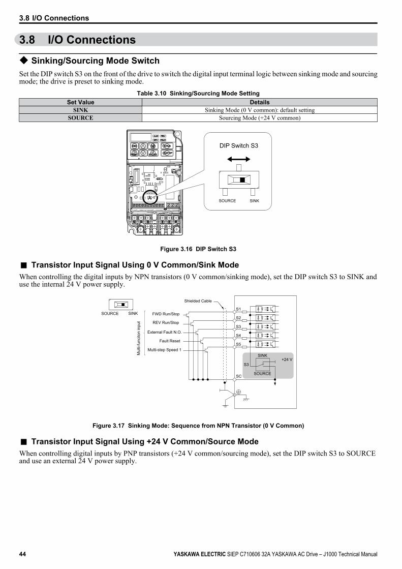
3.8 I/O Connections
u Sinking/Sourcing Mode SwitchSet the DIP switch S3 on the front of the drive to switch the digital input terminal logic between sinking mode and sourcingmode; the drive is preset to sinking mode.
Table 3.10 Sinking/Sourcing Mode SettingSet Value Details
SINK Sinking Mode (0 V common): default settingSOURCE Sourcing Mode (+24 V common)
SINKSOURCE
DIP Switch S3
Figure 3.16 DIP Switch S3
n Transistor Input Signal Using 0 V Common/Sink ModeWhen controlling the digital inputs by NPN transistors (0 V common/sinking mode), set the DIP switch S3 to SINK anduse the internal 24 V power supply.
S1SINKSOURCE
S2
S3
S3+24 V
S4
S5
SC
SINK
SOURCE
FWD Run/Stop
REV Run/Stop
External Fault N.O.
Fault Reset
Multi-step Speed 1
Shielded Cable
Mul
ti-fu
ncito
n in
put
Figure 3.17 Sinking Mode: Sequence from NPN Transistor (0 V Common)
n Transistor Input Signal Using +24 V Common/Source ModeWhen controlling digital inputs by PNP transistors (+24 V common/sourcing mode), set the DIP switch S3 to SOURCEand use an external 24 V power supply.
3.8 I/O Connections
44 YASKAWA ELECTRIC SIEP C710606 32A YASKAWA AC Drive – J1000 Technical Manual
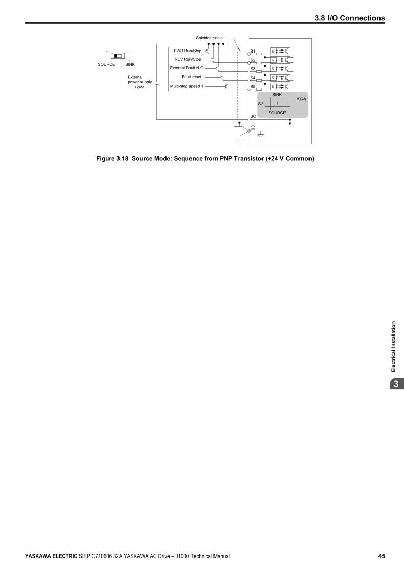
S1
+24V
S2
S3
+24V
S4
S5
SC
S3
SINKSOURCE
SINK
SOURCE
Externalpower supply
FWD Run/Stop
REV Run/Stop
External Fault N.O.
Fault reset
Multi-step speed 1
Shielded cable
Figure 3.18 Source Mode: Sequence from PNP Transistor (+24 V Common)
3.8 I/O Connections
YASKAWA ELECTRIC SIEP C710606 32A YASKAWA AC Drive – J1000 Technical Manual 45
3El
ectr
ical
Inst
alla
tion
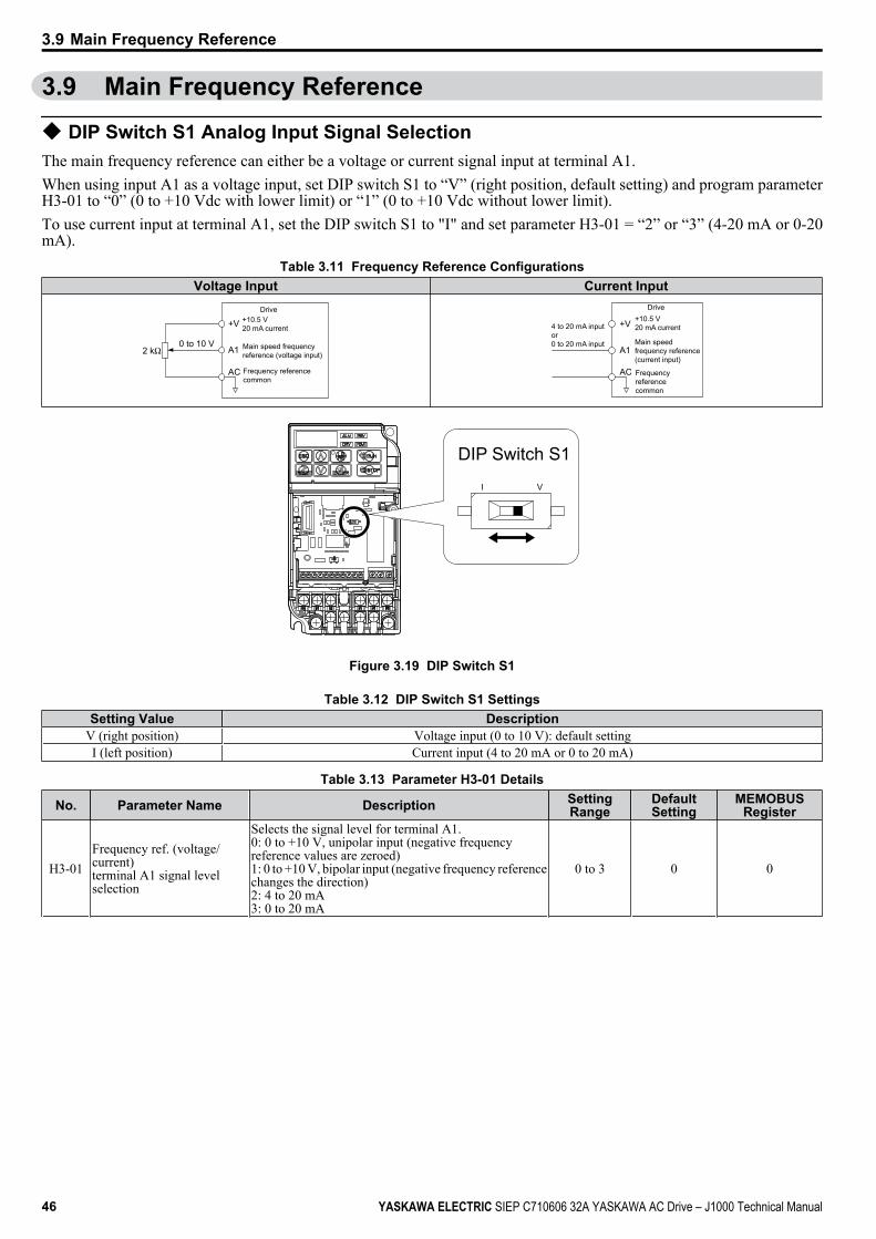
3.9 Main Frequency Reference
u DIP Switch S1 Analog Input Signal SelectionThe main frequency reference can either be a voltage or current signal input at terminal A1.When using input A1 as a voltage input, set DIP switch S1 to “V” (right position, default setting) and program parameterH3-01 to “0” (0 to +10 Vdc with lower limit) or “1” (0 to +10 Vdc without lower limit).To use current input at terminal A1, set the DIP switch S1 to "I" and set parameter H3-01 = “2” or “3” (4-20 mA or 0-20mA).
Table 3.11 Frequency Reference ConfigurationsVoltage Input Current Input
+10.5 V20 mA current
Main speed frequency reference (voltage input)
Frequency referencecommon
Drive
+V
A1
AC
0 to 10 V
+10.5 V20 mA current
Main speedfrequency reference(current input)
Frequency referencecommon
+V
A1
AC
Drive
4 to 20 mA inputor0 to 20 mA input
I V
DIP Switch S1
Figure 3.19 DIP Switch S1
Table 3.12 DIP Switch S1 SettingsSetting Value Description
V (right position) Voltage input (0 to 10 V): default settingI (left position) Current input (4 to 20 mA or 0 to 20 mA)
Table 3.13 Parameter H3-01 Details
No. Parameter Name Description SettingRange
DefaultSetting
MEMOBUSRegister
H3-01Frequency ref. (voltage/current)terminal A1 signal levelselection
Selects the signal level for terminal A1.0: 0 to +10 V, unipolar input (negative frequencyreference values are zeroed)1: 0 to +10 V, bipolar input (negative frequency referencechanges the direction)2: 4 to 20 mA3: 0 to 20 mA
0 to 3 0 0
3.9 Main Frequency Reference
46 YASKAWA ELECTRIC SIEP C710606 32A YASKAWA AC Drive – J1000 Technical Manual
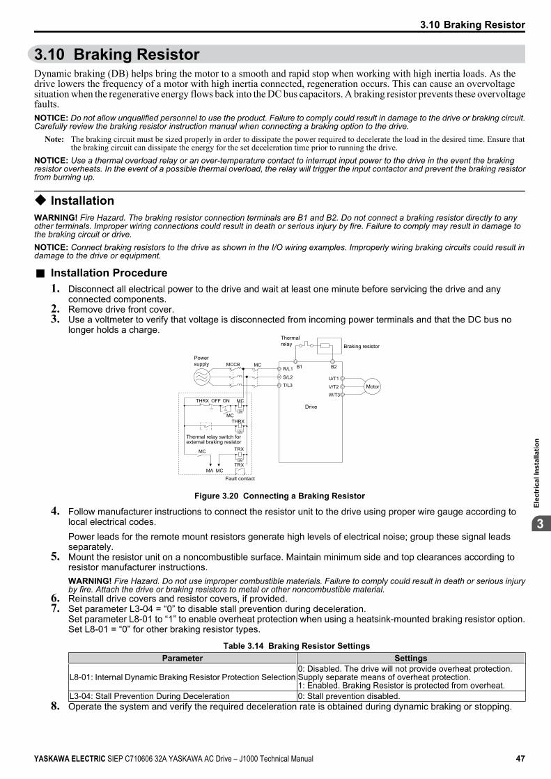
3.10 Braking ResistorDynamic braking (DB) helps bring the motor to a smooth and rapid stop when working with high inertia loads. As thedrive lowers the frequency of a motor with high inertia connected, regeneration occurs. This can cause an overvoltagesituation when the regenerative energy flows back into the DC bus capacitors. A braking resistor prevents these overvoltagefaults.NOTICE: Do not allow unqualified personnel to use the product. Failure to comply could result in damage to the drive or braking circuit.Carefully review the braking resistor instruction manual when connecting a braking option to the drive.
Note: The braking circuit must be sized properly in order to dissipate the power required to decelerate the load in the desired time. Ensure thatthe braking circuit can dissipate the energy for the set deceleration time prior to running the drive.
NOTICE: Use a thermal overload relay or an over-temperature contact to interrupt input power to the drive in the event the brakingresistor overheats. In the event of a possible thermal overload, the relay will trigger the input contactor and prevent the braking resistorfrom burning up.
u InstallationWARNING! Fire Hazard. The braking resistor connection terminals are B1 and B2. Do not connect a braking resistor directly to anyother terminals. Improper wiring connections could result in death or serious injury by fire. Failure to comply may result in damage tothe braking circuit or drive.NOTICE: Connect braking resistors to the drive as shown in the I/O wiring examples. Improperly wiring braking circuits could result indamage to the drive or equipment.
n Installation Procedure1. Disconnect all electrical power to the drive and wait at least one minute before servicing the drive and any
connected components.2. Remove drive front cover.3. Use a voltmeter to verify that voltage is disconnected from incoming power terminals and that the DC bus no
longer holds a charge.
Powersupply
Thermal relay
Motor
Drive
Braking resistor
Thermal relay switch forexternal braking resistor
Fault contact
MC
SA
SA
SA
MCON
MC
OFFTHRX
THRX
TRXMC
TRXMA MC
R/L1 B1 B2
S/L2
T/L3U/T1
V/T2
W/T3
MCCB
Figure 3.20 Connecting a Braking Resistor
4. Follow manufacturer instructions to connect the resistor unit to the drive using proper wire gauge according tolocal electrical codes.Power leads for the remote mount resistors generate high levels of electrical noise; group these signal leadsseparately.
5. Mount the resistor unit on a noncombustible surface. Maintain minimum side and top clearances according toresistor manufacturer instructions.WARNING! Fire Hazard. Do not use improper combustible materials. Failure to comply could result in death or serious injuryby fire. Attach the drive or braking resistors to metal or other noncombustible material.
6. Reinstall drive covers and resistor covers, if provided.7. Set parameter L3-04 = “0” to disable stall prevention during deceleration.
Set parameter L8-01 to “1” to enable overheat protection when using a heatsink-mounted braking resistor option.Set L8-01 = “0” for other braking resistor types.
Table 3.14 Braking Resistor SettingsParameter Settings
L8-01: Internal Dynamic Braking Resistor Protection Selection0: Disabled. The drive will not provide overheat protection.Supply separate means of overheat protection.1: Enabled. Braking Resistor is protected from overheat.
L3-04: Stall Prevention During Deceleration 0: Stall prevention disabled.8. Operate the system and verify the required deceleration rate is obtained during dynamic braking or stopping.
3.10 Braking Resistor
YASKAWA ELECTRIC SIEP C710606 32A YASKAWA AC Drive – J1000 Technical Manual 47
3El
ectr
ical
Inst
alla
tion

3.11 Interlocking with Connected MachineryFor safety reasons, applications that may be affected by the operation status of the drive should be set up so that operationcan only occur when the drive is ready to operate. A "Drive ready" and "Fault" signal should be assigned to the multi-function outputs to guarantee interlock with application.
u Drive Ready SignalThe "Drive ready" signal is output to one of the multi-function terminals after the drive has booted up and there is no faultpresent. It indicates that the drive is ready for operation.• The power is off.• A fault situation is present.• There is a problem with the drive internal power supply.• Parameter settings restrict a Run command from being entered.• An overvoltage or undervoltage situation is present so that when the Run command is given a fault is immediately
triggered.• The drive is in the programming mode and parameter settings restrict a Run command from being entered in the
programming mode.
3.11 Interlocking with Connected Machinery
48 YASKAWA ELECTRIC SIEP C710606 32A YASKAWA AC Drive – J1000 Technical Manual

3.12 Wiring ChecklistNo. Item Page
Drive, peripherals, option cards1 Check drive model number to ensure receipt of correct model. 172 Check for correct braking resistors, DC reactors, noise filters, and other peripheral devices. 47
Installation area and physical setup3 Ensure area surrounding the drive complies with specifications. 26
Power supply voltage, output voltage4 The voltage from the power supply should fall within the input voltage specification range of the drive. 865 The voltage rating for the motor should match the drive output specifications. 17
Main circuit wiring6 Confirm proper branch circuit protection exists per National and Local codes. 327 Properly wire the power supply to drive terminals R/L1, S/L2 and T/L3. 34
8Properly wire the drive and motor together.The motor lines and drive output terminals R/T1, V/T2 and W/T3 should match in order to produce the desiredphase order. If the phase order is incorrect, the drive will rotate in the opposite direction.
38
9 Use 600 Vac vinyl-sheathed wire for the power supply and motor lines. 37
10 Use the correct wire gauges for the main circuit. Refer to Wire Gauge and Torque Specifications on page 37,Table 3.2, or Table 3.3. 37
• When using comparatively long motor cable, calculate the amount of voltage drop.
3 x voltage resistance (Ω/km) x cable length (m) x motor rated current (A) x 10-3
Motor rated voltage (V) x 0.02 ≥ 37
• If the cable between the drive and motor exceeds 50 m, adjust the carrier frequency (C6-02) accordingly. 3811 Properly ground the drive. Review page 38. 38
12 Tightly fasten all terminal screws (control circuit terminals, grounding terminals).Refer to Wire Gauge and Torque Specifications on page 37, Table 3.2, or Table 3.3. 37
13
Set up overload protection circuits when running multiple motors from a single drive.
M1OL1
OL2
OLn
MC1
MC2
MCn
M2
Mn
Drive
MC1 - MCn OL 1 - OLn
... magnetic contactor ... thermal relay
Power supply
Note: Close MC1 through MCn before operating the drive.
-
14 If using a braking resistor or dynamic braking resistor unit, install a magnetic contactor. Properly install theresistor, and ensure that overload protection shuts off the power supply. 47
15 Verify phase advancing capacitors are NOT installed on the output side of the drive. -Control circuit wiring
16 Use twisted-pair cables for all drive control circuit wiring. 4017 Ground the shields of shielded wiring to the GND terminal. 42
18 If using a 3-Wire sequence, properly set parameters for multi-function contact input terminals S1 through S5,and properly wire control circuits. 33
19 Check for any other wiring mistakes.Only use a multimeter to check wiring. -
20 Properly fasten the control circuit terminal screws in the drive.Refer to Wire Gauge and Torque Specifications on page 37, Table 3.2, or Table 3.3. 37
21 Pick up all wire clippings. -22 Ensure that no frayed wires on the terminal block are touching other terminals or connections. -23 Properly separate control circuit wiring and main circuit wiring. -24 Analog signal line wiring should not exceed 50 m. -
3.12 Wiring Checklist
YASKAWA ELECTRIC SIEP C710606 32A YASKAWA AC Drive – J1000 Technical Manual 49
3El
ectr
ical
Inst
alla
tion
3.12 Wiring Checklist
This Page Intentionally Blank
50 YASKAWA ELECTRIC SIEP C710606 32A YASKAWA AC Drive – J1000 Technical Manual
Start-Up Programming & OperationThis chapter explains the functions of the LED operator and how to program the drive for initialoperation.
4.1 SECTION SAFETY............................................................................................524.2 USING THE DIGITAL LED OPERATOR..........................................................544.3 THE DRIVE AND PROGRAMMING MODES....................................................574.4 START-UP FLOWCHART.................................................................................624.5 POWERING UP THE DRIVE.............................................................................634.6 NO-LOAD OPERATION TEST RUN.................................................................644.7 TEST RUN WITH LOAD CONNECTED............................................................654.8 VERIFYING AND BACKING UP PARAMETER SETTINGS............................664.9 TEST RUN CHECKLIST...................................................................................67
4
YASKAWA ELECTRIC SIEP C710606 32A YASKAWA AC Drive – J1000 Technical Manual 51
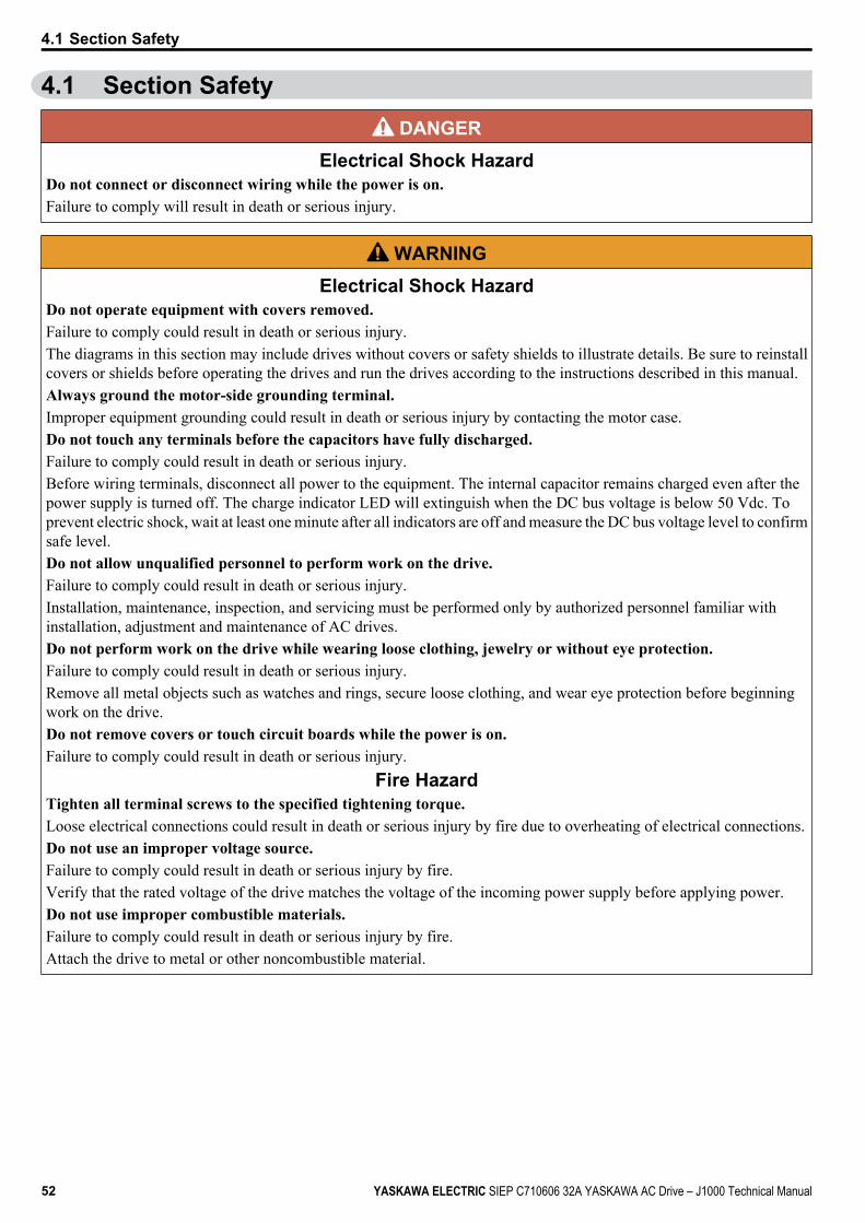
4.1 Section Safety DANGER
Electrical Shock HazardDo not connect or disconnect wiring while the power is on.Failure to comply will result in death or serious injury.
WARNINGElectrical Shock Hazard
Do not operate equipment with covers removed.Failure to comply could result in death or serious injury.The diagrams in this section may include drives without covers or safety shields to illustrate details. Be sure to reinstallcovers or shields before operating the drives and run the drives according to the instructions described in this manual.Always ground the motor-side grounding terminal.Improper equipment grounding could result in death or serious injury by contacting the motor case.Do not touch any terminals before the capacitors have fully discharged.Failure to comply could result in death or serious injury.Before wiring terminals, disconnect all power to the equipment. The internal capacitor remains charged even after thepower supply is turned off. The charge indicator LED will extinguish when the DC bus voltage is below 50 Vdc. Toprevent electric shock, wait at least one minute after all indicators are off and measure the DC bus voltage level to confirmsafe level.Do not allow unqualified personnel to perform work on the drive.Failure to comply could result in death or serious injury.Installation, maintenance, inspection, and servicing must be performed only by authorized personnel familiar withinstallation, adjustment and maintenance of AC drives.Do not perform work on the drive while wearing loose clothing, jewelry or without eye protection.Failure to comply could result in death or serious injury.Remove all metal objects such as watches and rings, secure loose clothing, and wear eye protection before beginningwork on the drive.Do not remove covers or touch circuit boards while the power is on.Failure to comply could result in death or serious injury.
Fire HazardTighten all terminal screws to the specified tightening torque.Loose electrical connections could result in death or serious injury by fire due to overheating of electrical connections.Do not use an improper voltage source.Failure to comply could result in death or serious injury by fire.Verify that the rated voltage of the drive matches the voltage of the incoming power supply before applying power.Do not use improper combustible materials.Failure to comply could result in death or serious injury by fire.Attach the drive to metal or other noncombustible material.
4.1 Section Safety
52 YASKAWA ELECTRIC SIEP C710606 32A YASKAWA AC Drive – J1000 Technical Manual
NOTICEObserve proper electrostatic discharge procedures (ESD) when handling the drive and circuit boards.Failure to comply may result in ESD damage to the drive circuitry.Never connect or disconnect the motor from the drive while the drive is outputting voltage.Improper equipment sequencing could result in damage to the drive.Do not use unshielded cable for control wiring.Failure to comply may cause electrical interference resulting in poor system performance. Use shielded twisted-pair wiresand ground the shield to the ground terminal of the drive.Do not allow unqualified personnel to use the product.Failure to comply could result in damage to the drive or braking circuit.Carefully review instruction manual TOBPC72060000 when connecting a braking option to the drive.Do not modify the drive circuitry.Failure to comply could result in damage to the drive and will void warranty.Yaskawa is not responsible for any modification of the product made by the user. This product must not be modified.Check all the wiring to ensure that all connections are correct after installing the drive and connecting any otherdevices.Failure to comply could result in damage to the drive.
4.1 Section Safety
YASKAWA ELECTRIC SIEP C710606 32A YASKAWA AC Drive – J1000 Technical Manual 53
4St
art-U
p Pr
ogra
mm
ing
& O
pera
tion
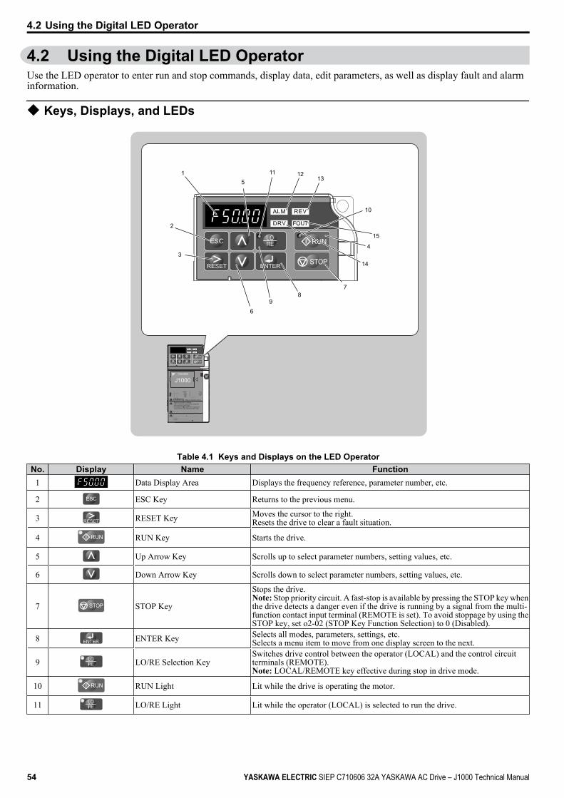
4.2 Using the Digital LED OperatorUse the LED operator to enter run and stop commands, display data, edit parameters, as well as display fault and alarminformation.
u Keys, Displays, and LEDs
P
9
51
2
3
6
78
10
STOP
11
14
1213
15
4
J1000
STOP
据据据据据据据据据据据据据据据据据据据据据据据据据据据据据据据据据据据 5据据据据据据据据据据据据据据据据据据据400V据据据据据据据据据据据据据据据据据据据据据据据据据据据据据据据据据据据据据据据据据
据据据据据据据据据据据据据据据据据据
Read manual before installing.Wait 5 minutes for capacitor discharge afterdisconnecting power supply.To conform to requirements, make sureto ground the supply neutral for 400V class.
Risk of electric shock.WARNING
1 据据据据据2 据据据据据据3 据据据据据4 据据据据5 据据据据
:::::
::::
6 据据据7 据据据据据8 据据据据据据9 据据据据据据据
Table 4.1 Keys and Displays on the LED OperatorNo. Display Name Function
1 Data Display Area Displays the frequency reference, parameter number, etc.
2 ESC Key Returns to the previous menu.
3 RESET Key Moves the cursor to the right.Resets the drive to clear a fault situation.
4 RUN Key Starts the drive.
5 Up Arrow Key Scrolls up to select parameter numbers, setting values, etc.
6 Down Arrow Key Scrolls down to select parameter numbers, setting values, etc.
7 STOP STOP Key
Stops the drive.Note: Stop priority circuit. A fast-stop is available by pressing the STOP key whenthe drive detects a danger even if the drive is running by a signal from the multi-function contact input terminal (REMOTE is set). To avoid stoppage by using theSTOP key, set o2-02 (STOP Key Function Selection) to 0 (Disabled).
8 ENTER Key Selects all modes, parameters, settings, etc.Selects a menu item to move from one display screen to the next.
9 LO/RE Selection KeySwitches drive control between the operator (LOCAL) and the control circuitterminals (REMOTE).Note: LOCAL/REMOTE key effective during stop in drive mode.
10 RUN Light Lit while the drive is operating the motor.
11 LO/RE Light Lit while the operator (LOCAL) is selected to run the drive.
4.2 Using the Digital LED Operator
54 YASKAWA ELECTRIC SIEP C710606 32A YASKAWA AC Drive – J1000 Technical Manual

No. Display Name Function12 ALM LED Light
Refer to LED Screen Displays on page 55.13 REV LED Light
14 DRV LED Light
15 FOUT LED Light
u Digital Text DisplayText appears on the LED Operator as shown below. This section explains the meaning of text as it appears on the displayscreen.
Lit Flashing
Table 4.2 Digital Text DisplayText LED Text LED Text LED Text LED
0 9 I R1 A J S2 B K T3 C L U
4 D M <1> V
5 E N W <1>
6 F O X none7 G P Y8 H Q Z none
<1> Displayed in two digits.
u LED Screen DisplaysDisplay Lit Flashing Off
When the drive detects an alarm or error • When an alarm occurs• oPE detected Normal state (no fault or alarm)
Motor is rotating in reverse — Motor is rotating forward
Drive Mode — Programming Mode
Displays output frequency (Hz) — —
As illustrated inthis manual
STOPu LO/RE LED and RUN LED IndicationsLED Lit Flashing Flashing Quickly <1> Off
When run command isselected from LED operator(LOCAL)
— —Run command is selected fromdevice other than LED operator(REMOTE)
During run• During deceleration to stop• When a run command is input
and frequency reference is 0
• During deceleration at a fast-stop.
• During stop by interlockoperation.
During stop
As shown
<1> Refer to Figure 4.1 for the difference between “flashing” and “flashing quickly”.
4.2 Using the Digital LED Operator
YASKAWA ELECTRIC SIEP C710606 32A YASKAWA AC Drive – J1000 Technical Manual 55
4St
art-U
p Pr
ogra
mm
ing
& O
pera
tion
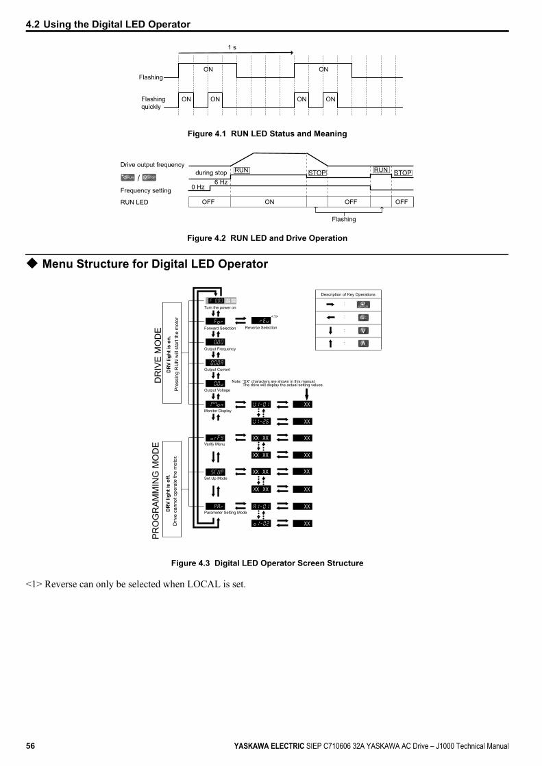
Flashing
ON ON
ON
ON ON
ON
1 s
Flashingquickly
Figure 4.1 RUN LED Status and Meaning
/
Drive output frequencyduring stop
Frequency setting
OFF ON
Flashing
OFFOFFRUN LED
RUN
0 Hz6 Hz
RUNSTOP STOP
Figure 4.2 RUN LED and Drive Operation
u Menu Structure for Digital LED Operator
XXXX
XX
XX
XX
XX
XX
XX
XX
XXXX
XXXX XX
XXXX
:
:
:
:
Turn the power on
Forward Selection Reverse Selection
Output Frequency
Output Current
Output Voltage
Monitor Display
Note: “XX” characters are shown in this manual. The drive will display the actual setting values.
<1>
Verify Menu
Set Up Mode
Parameter Setting Mode
Description of Key Operations
PR
OG
RA
MM
ING
MO
DE
DR
IVE
MO
DE
Figure 4.3 Digital LED Operator Screen Structure
<1> Reverse can only be selected when LOCAL is set.
4.2 Using the Digital LED Operator
56 YASKAWA ELECTRIC SIEP C710606 32A YASKAWA AC Drive – J1000 Technical Manual
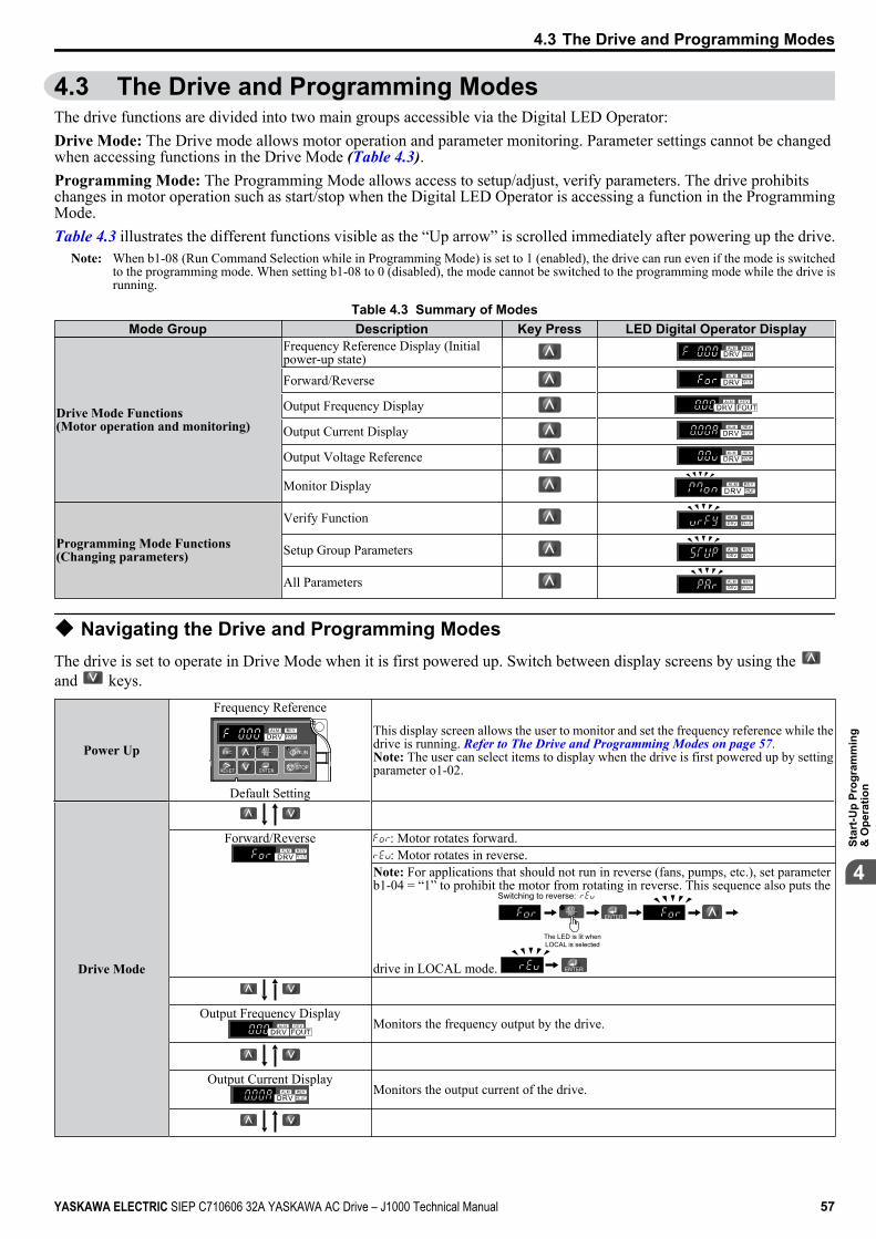
4.3 The Drive and Programming ModesThe drive functions are divided into two main groups accessible via the Digital LED Operator:Drive Mode: The Drive mode allows motor operation and parameter monitoring. Parameter settings cannot be changedwhen accessing functions in the Drive Mode (Table 4.3).Programming Mode: The Programming Mode allows access to setup/adjust, verify parameters. The drive prohibitschanges in motor operation such as start/stop when the Digital LED Operator is accessing a function in the ProgrammingMode.Table 4.3 illustrates the different functions visible as the “Up arrow” is scrolled immediately after powering up the drive.
Note: When b1-08 (Run Command Selection while in Programming Mode) is set to 1 (enabled), the drive can run even if the mode is switchedto the programming mode. When setting b1-08 to 0 (disabled), the mode cannot be switched to the programming mode while the drive isrunning.
Table 4.3 Summary of ModesMode Group Description Key Press LED Digital Operator Display
Drive Mode Functions(Motor operation and monitoring)
Frequency Reference Display (Initialpower-up state)
STOP
Forward/Reverse
STOP
Output Frequency Display
STOP
Output Current Display
STOP
Output Voltage Reference
STOP
Monitor Display
STOP
Programming Mode Functions(Changing parameters)
Verify Function
STOP
Setup Group Parameters
STOP
All Parameters
STOPu Navigating the Drive and Programming ModesThe drive is set to operate in Drive Mode when it is first powered up. Switch between display screens by using the and keys.
Power Up
Frequency Reference
STOP
Default Setting
This display screen allows the user to monitor and set the frequency reference while thedrive is running. Refer to The Drive and Programming Modes on page 57.Note: The user can select items to display when the drive is first powered up by settingparameter o1-02.
Drive Mode
Forward/Reverse
STOP
: Motor rotates forward.: Motor rotates in reverse.
Note: For applications that should not run in reverse (fans, pumps, etc.), set parameterb1-04 = “1” to prohibit the motor from rotating in reverse. This sequence also puts the
drive in LOCAL mode.
The LED is lit when LOCAL is selected
Switching to reverse:
Output Frequency Display
STOP
Monitors the frequency output by the drive.
Output Current Display
STOP
Monitors the output current of the drive.
4.3 The Drive and Programming Modes
YASKAWA ELECTRIC SIEP C710606 32A YASKAWA AC Drive – J1000 Technical Manual 57
4St
art-U
p Pr
ogra
mm
ing
& O
pera
tion
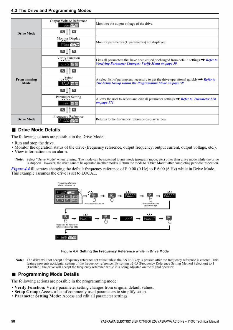
Drive Mode
Output Voltage Reference
STOP
Monitors the output voltage of the drive.
Monitor Display
STOP
Monitor parameters (U parameters) are displayed.
ProgrammingMode
Verify Function
STOP
Lists all parameters that have been edited or changed from default settings. Refer to Verifying Parameter Changes: Verify Menu on page 59.
Setup
STOP
A select list of parameters necessary to get the drive operational quickly. Refer to The Setup Group within the Programming Mode on page 59.
Parameter Setting
STOP
Allows the user to access and edit all parameter settings. Refer to Parameter List on page 171.
Drive ModeFrequency Reference
STOP
Returns to the frequency reference display screen.
n Drive Mode DetailsThe following actions are possible in the Drive Mode:• Run and stop the drive.• Monitor the operation status of the drive (frequency reference, output frequency, output current, output voltage, etc.).• View information on an alarm.
Note: Select "Drive Mode" when running. The mode can be switched to any mode (program mode, etc.) other than drive mode while the driveis stopped. However, the drive cannot be operated in other modes. Return the mode to "Drive Mode" after completing periodic inspection.
Figure 4.4 illustrates changing the default frequency reference of F 0.00 (0 Hz) to F 6.00 (6 Hz) while in Drive Mode.This example assumes the drive is set to LOCAL.
STOP
Frequency reference display at power up
Press to select LOCAL
Press until the frequency reference becomes 6 Hz
Press to select thedigit to the right
Figure 4.4 Setting the Frequency Reference while in Drive Mode
Note: The drive will not accept a frequency reference set value unless the ENTER key is pressed after the frequency reference is entered. Thisfeature prevents accidental setting of the frequency reference. By setting o2-05 (Frequency Reference Setting Method Selection) to 1(Enabled), the drive will accept the frequency reference while it is being adjusted on the digital operator.
n Programming Mode DetailsThe following actions are possible in the programming mode:• Verify Function: Verify parameter setting changes from original default values.• Setup Group: Access a list of commonly used parameters to simplify setup.• Parameter Setting Mode: Access and edit all parameter settings.
4.3 The Drive and Programming Modes
58 YASKAWA ELECTRIC SIEP C710606 32A YASKAWA AC Drive – J1000 Technical Manual
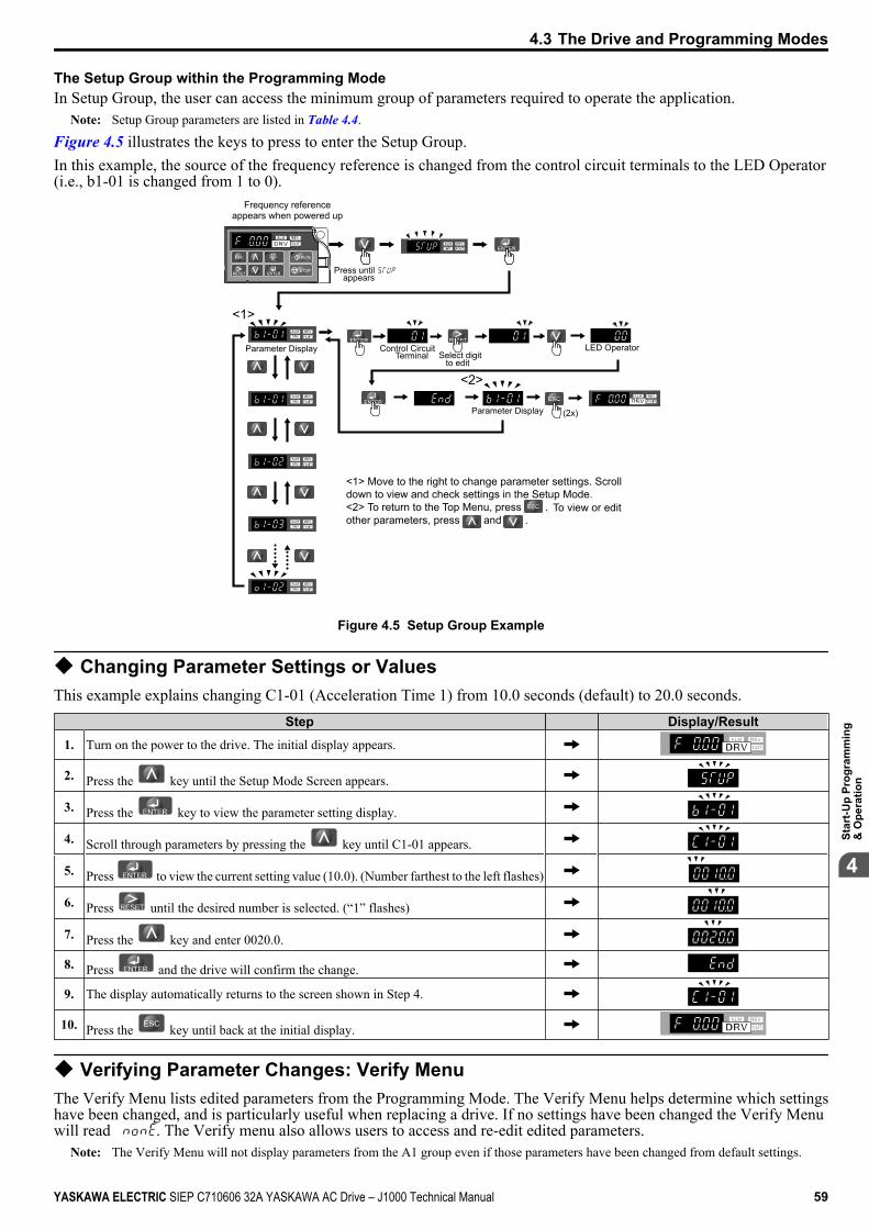
The Setup Group within the Programming ModeIn Setup Group, the user can access the minimum group of parameters required to operate the application.
Note: Setup Group parameters are listed in Table 4.4.
Figure 4.5 illustrates the keys to press to enter the Setup Group.In this example, the source of the frequency reference is changed from the control circuit terminals to the LED Operator(i.e., b1-01 is changed from 1 to 0).
STOP
STOP
STOP
STOP
STOP
(2x)
<1> Move to the right to change parameter settings. Scroll down to view and check settings in the Setup Mode.<2> To return to the Top Menu, press . To view or editother parameters, press and .
Control CircuitTerminal Select digit
to edit
Parameter Display
LED Operator
Frequency reference appears when powered up
Parameter Display
Press until appears
<1>
<2>
Figure 4.5 Setup Group Example
u Changing Parameter Settings or ValuesThis example explains changing C1-01 (Acceleration Time 1) from 10.0 seconds (default) to 20.0 seconds.
Step Display/Result
1. Turn on the power to the drive. The initial display appears.
2. Press the key until the Setup Mode Screen appears.
3. Press the key to view the parameter setting display.
4. Scroll through parameters by pressing the key until C1-01 appears.
5. Press to view the current setting value (10.0). (Number farthest to the left flashes)
6. Press until the desired number is selected. (“1” flashes)
7. Press the key and enter 0020.0.
8. Press and the drive will confirm the change.
9. The display automatically returns to the screen shown in Step 4.
10. Press the key until back at the initial display.
u Verifying Parameter Changes: Verify MenuThe Verify Menu lists edited parameters from the Programming Mode. The Verify Menu helps determine which settingshave been changed, and is particularly useful when replacing a drive. If no settings have been changed the Verify Menuwill read . The Verify menu also allows users to access and re-edit edited parameters.
Note: The Verify Menu will not display parameters from the A1 group even if those parameters have been changed from default settings.
4.3 The Drive and Programming Modes
YASKAWA ELECTRIC SIEP C710606 32A YASKAWA AC Drive – J1000 Technical Manual 59
4St
art-U
p Pr
ogra
mm
ing
& O
pera
tion
The following example is a continuation of the steps beginning on page 59. Here, parameter C1-01 is accessed using theVerify Menu and is changed again to 20.0 s.To check the list of edited parameters:
Step Display/Result
1. Turn on the power to the drive. The initial display appears.
2. Press until the display shows the “Verify” representation.
3.Press to enter the list of parameters that have been edited from their originaldefault settings.
Scroll through the list by pressing the key.
4. Press the key until C1-01 appears.
5. Press the key to access the setting value. (number farthest to the left flashes)
u Switching Between LOCAL and REMOTEEntering the run command using the LED operator is referred to as LOCAL, while entering the run command from anexternal device via the control circuit terminals or network option unit is referred to as REMOTE.WARNING! Sudden Movement Hazard. The drive may start unexpectedly if the Run command is already applied when switching fromLOCAL mode to REMOTE mode when b1-07 = 1, resulting in death or serious injury. Be sure all personnel are clear of rotating machineryand electrical connections prior to switching between LOCAL mode and REMOTE mode.
There are two ways to switch between LOCAL and REMOTE.Note: 1. After selecting LOCAL, the LO/RE light will remain lit.
2. The drive will not allow the user to switch between LOCAL and REMOTE during run.
n Using the LO/RE Key on the LED Operator
Step Display/Result
1. Turn on the power to the drive. The initial display appears.
2. Press . The LO/RE light will light up. The drive is now in Local.
To set the drive for REMOTE operation, press the key again.STOP
n Using Input Terminals S1 through S5 to Switch between LO/RESwitch between LOCAL and REMOTE using one of the digital input terminals S1 through S5 (set the correspondingparameter H1-01 through H1-05 to “1”).Follow the example below to set the digital input terminals.
Note: 1. For a list of digital input selections, Refer to Parameter List on page 171.2. Setting a multi-function input terminal to a value of 1 disables the LO/RE key on the LED operator.
u Parameters Available in the Setup Groupn Setup Mode (STUP)Parameters used for this drive are classified into A to U. To simplify the drive setup, frequently used parameters are selectedand input into Setup Mode.
1. To set a parameter, the Setup Mode must be displayed first. Press the Up/Down key until is displayed.2. Select the parameter and change the setting. Table 4.4 lists parameters available in the Setup group. If the desired
parameter cannot be set in the Setup mode, use the Parameter Setting mode.
Table 4.4 Setup Group ParametersParameter Name
b1-01 Frequency Reference Selectionb1-02 Run Command Selectionb1-03 Stop Method SelectionC1-01 Acceleration Time 1C1-02 Deceleration Time 1
Parameter NameC6-01 Duty SelectionC6-02 Carrier Frequency Selectiond1-01 Frequency Reference 1d1-02 Frequency Reference 2d1-03 Frequency Reference 3
4.3 The Drive and Programming Modes
60 YASKAWA ELECTRIC SIEP C710606 32A YASKAWA AC Drive – J1000 Technical Manual
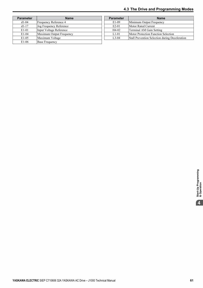
Parameter Named1-04 Frequency Reference 4d1-17 Jog Frequency ReferenceE1-01 Input Voltage ReferenceE1-04 Maximum Output FrequencyE1-05 Maximum VoltageE1-06 Base Frequency
Parameter NameE1-09 Minimum Output FrequencyE2-01 Motor Rated CurrentH4-02 Terminal AM Gain SettingL1-01 Motor Protection Function SelectionL3-04 Stall Prevention Selection during Deceleration
4.3 The Drive and Programming Modes
YASKAWA ELECTRIC SIEP C710606 32A YASKAWA AC Drive – J1000 Technical Manual 61
4St
art-U
p Pr
ogra
mm
ing
& O
pera
tion
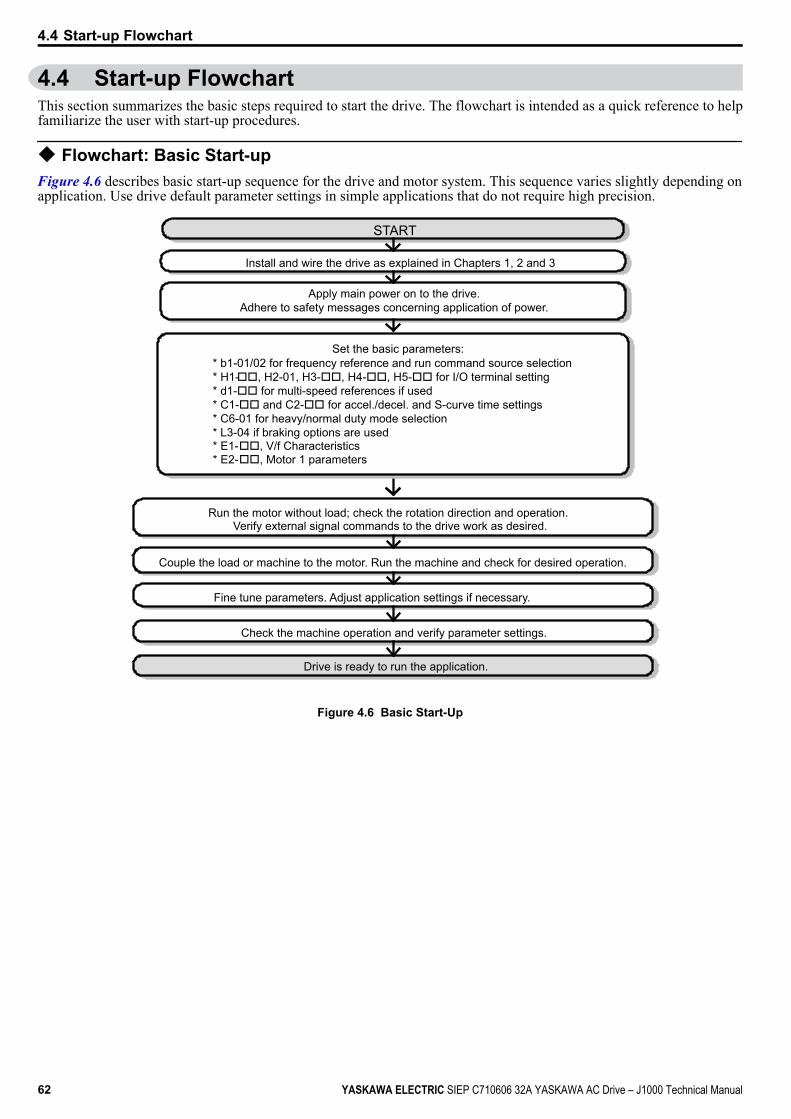
4.4 Start-up FlowchartThis section summarizes the basic steps required to start the drive. The flowchart is intended as a quick reference to helpfamiliarize the user with start-up procedures.
u Flowchart: Basic Start-upFigure 4.6 describes basic start-up sequence for the drive and motor system. This sequence varies slightly depending onapplication. Use drive default parameter settings in simple applications that do not require high precision.
Install and wire the drive as explained in Chapters 1, 2 and 3
Run the motor without load; check the rotation direction and operation.Verify external signal commands to the drive work as desired.
Couple the load or machine to the motor. Run the machine and check for desired operation.
Fine tune parameters. Adjust application settings if necessary.
Check the machine operation and verify parameter settings.
Drive is ready to run the application.
START
Apply main power on to the drive.Adhere to safety messages concerning application of power.
Set the basic parameters:* b1-01/02 for frequency reference and run command source selection* H1-oo, H2-01, H3-oo, H4-oo, H5-oo for I/O terminal setting* d1-oo for multi-speed references if used* C1-oo and C2-oo for accel./decel. and S-curve time settings* C6-01 for heavy/normal duty mode selection* L3-04 if braking options are used * E1-oo, V/f Characteristics* E2-oo, Motor 1 parameters
Figure 4.6 Basic Start-Up
4.4 Start-up Flowchart
62 YASKAWA ELECTRIC SIEP C710606 32A YASKAWA AC Drive – J1000 Technical Manual
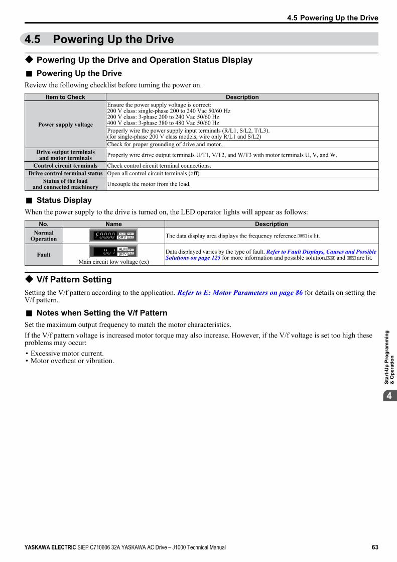
4.5 Powering Up the Drive
u Powering Up the Drive and Operation Status Displayn Powering Up the DriveReview the following checklist before turning the power on.
Item to Check Description
Power supply voltage
Ensure the power supply voltage is correct:200 V class: single-phase 200 to 240 Vac 50/60 Hz200 V class: 3-phase 200 to 240 Vac 50/60 Hz400 V class: 3-phase 380 to 480 Vac 50/60 HzProperly wire the power supply input terminals (R/L1, S/L2, T/L3).(for single-phase 200 V class models, wire only R/L1 and S/L2)Check for proper grounding of drive and motor.
Drive output terminalsand motor terminals Properly wire drive output terminals U/T1, V/T2, and W/T3 with motor terminals U, V, and W.
Control circuit terminals Check control circuit terminal connections.Drive control terminal status Open all control circuit terminals (off).
Status of the loadand connected machinery Uncouple the motor from the load.
n Status DisplayWhen the power supply to the drive is turned on, the LED operator lights will appear as follows:
No. Name DescriptionNormal
Operation
STOP
The data display area displays the frequency reference. is lit.
Fault
STOP
Main circuit low voltage (ex)
Data displayed varies by the type of fault. Refer to Fault Displays, Causes and Possible Solutions on page 125 for more information and possible solution. and are lit.
u V/f Pattern SettingSetting the V/f pattern according to the application. Refer to E: Motor Parameters on page 86 for details on setting theV/f pattern.
n Notes when Setting the V/f PatternSet the maximum output frequency to match the motor characteristics.If the V/f pattern voltage is increased motor torque may also increase. However, if the V/f voltage is set too high theseproblems may occur:• Excessive motor current.• Motor overheat or vibration.
4.5 Powering Up the Drive
YASKAWA ELECTRIC SIEP C710606 32A YASKAWA AC Drive – J1000 Technical Manual 63
4St
art-U
p Pr
ogra
mm
ing
& O
pera
tion
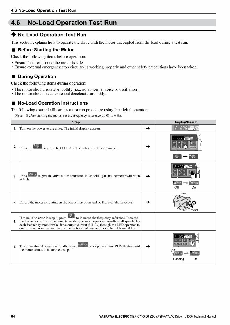
4.6 No-Load Operation Test Run
u No-Load Operation Test RunThis section explains how to operate the drive with the motor uncoupled from the load during a test run.
n Before Starting the MotorCheck the following items before operation:• Ensure the area around the motor is safe.• Ensure external emergency stop circuitry is working properly and other safety precautions have been taken.
n During OperationCheck the following items during operation:• The motor should rotate smoothly (i.e., no abnormal noise or oscillation).• The motor should accelerate and decelerate smoothly.
n No-Load Operation InstructionsThe following example illustrates a test run procedure using the digital operator.
Note: Before starting the motor, set the frequency reference d1-01 to 6 Hz.
Step Display/Result
1. Turn on the power to the drive. The initial display appears.
2. Press the key to select LOCAL. The LO/RE LED will turn on. STOP
3. Press to give the drive a Run command. RUN will light and the motor will rotateat 6 Hz.
STOP
Off On
4. Ensure the motor is rotating in the correct direction and no faults or alarms occur.
Motor
Forward
5.If there is no error in step 4, press to increase the frequency reference. Increasethe frequency in 10 Hz increments verifying smooth operation results at all speeds. Foreach frequency, monitor the drive output current (U1-03) through the LED operator toconfirm the current is well below the motor rated current. Example: 6 Hz → 50 Hz.
6. The drive should operate normally. Press STOP to stop the motor. RUN flashes untilthe motor comes to a complete stop.
STOP
Flashing Off
4.6 No-Load Operation Test Run
64 YASKAWA ELECTRIC SIEP C710606 32A YASKAWA AC Drive – J1000 Technical Manual
4.7 Test Run with Load Connected
u Test Run with the Load ConnectedAfter performing a no-load test run connect the motor and proceed to run the motor and load together.
n Notes on Connected Machinery• Clear the area around the motor.• The motor should come to a complete stop without problems.• Connect the machinery.• Fasten all installation screws properly. Check that the motor and connected machinery are held in place.• Confirm that the Fast-stop circuit or mechanical safety measures operate correctly.• Be ready to press the STOP button in case of emergency.
n Checklist Before Operation• The motor should rotate in the proper direction.• The motor should accelerate and decelerate smoothly.
n Operating the Motor under Loaded ConditionsTest run the application similarly to the no-load test procedure when connecting the machinery to the motor.• Check monitor parameter U1-03 to ensure there is no overcurrent.• If the application permits running the load in the reverse direction, try changing motor direction and the frequency
reference while watching for abnormal motor oscillation or vibration.• Correct any problems that occurs with hunting, oscillation, or other control-related issues.
4.7 Test Run with Load Connected
YASKAWA ELECTRIC SIEP C710606 32A YASKAWA AC Drive – J1000 Technical Manual 65
4St
art-U
p Pr
ogra
mm
ing
& O
pera
tion
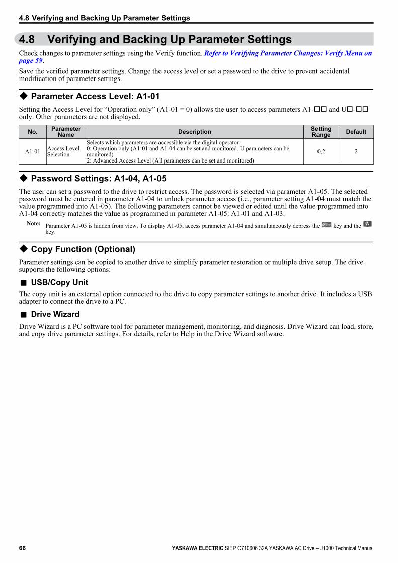
4.8 Verifying and Backing Up Parameter SettingsCheck changes to parameter settings using the Verify function. Refer to Verifying Parameter Changes: Verify Menu on page 59.Save the verified parameter settings. Change the access level or set a password to the drive to prevent accidentalmodification of parameter settings.
u Parameter Access Level: A1-01Setting the Access Level for “Operation only” (A1-01 = 0) allows the user to access parameters A1-oo and Uo-ooonly. Other parameters are not displayed.
No. ParameterName Description Setting
Range Default
A1-01 Access LevelSelection
Selects which parameters are accessible via the digital operator.0: Operation only (A1-01 and A1-04 can be set and monitored. U parameters can bemonitored)2: Advanced Access Level (All parameters can be set and monitored)
0,2 2
u Password Settings: A1-04, A1-05The user can set a password to the drive to restrict access. The password is selected via parameter A1-05. The selectedpassword must be entered in parameter A1-04 to unlock parameter access (i.e., parameter setting A1-04 must match thevalue programmed into A1-05). The following parameters cannot be viewed or edited until the value programmed intoA1-04 correctly matches the value as programmed in parameter A1-05: A1-01 and A1-03.
Note: Parameter A1-05 is hidden from view. To display A1-05, access parameter A1-04 and simultaneously depress the key and the key.
u Copy Function (Optional)Parameter settings can be copied to another drive to simplify parameter restoration or multiple drive setup. The drivesupports the following options:
n USB/Copy UnitThe copy unit is an external option connected to the drive to copy parameter settings to another drive. It includes a USBadapter to connect the drive to a PC.
n Drive WizardDrive Wizard is a PC software tool for parameter management, monitoring, and diagnosis. Drive Wizard can load, store,and copy drive parameter settings. For details, refer to Help in the Drive Wizard software.
4.8 Verifying and Backing Up Parameter Settings
66 YASKAWA ELECTRIC SIEP C710606 32A YASKAWA AC Drive – J1000 Technical Manual
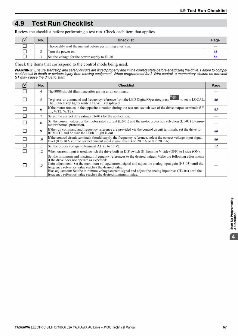
4.9 Test Run ChecklistReview the checklist before performing a test run. Check each item that applies.
No. Checklist Page1 Thoroughly read the manual before performing a test run. —2 Turn the power on. 633 Set the voltage for the power supply to E1-01. 86
Check the items that correspond to the control mode being used.WARNING! Ensure start/stop and safety circuits are wired properly and in the correct state before energizing the drive. Failure to complycould result in death or serious injury from moving equipment. When programmed for 3-Wire control, a momentary closure on terminalS1 may cause the drive to start.
No. Checklist Page4 The should illuminate after giving a run command. —
5 To give a run command and frequency reference from the LED Digital Operator, press to set to LOCAL.The LO/RE key lights while LOCAL is displayed.
60
6 If the motor rotates in the opposite direction during the test run, switch two of the drive output terminals (U/T1, V/T2, W/T3). 63
7 Select the correct duty rating (C6-01) for the application. —
8 Set the correct values for the motor rated current (E2-01) and the motor protection selection (L1-01) to ensuremotor thermal protection. —
9 If the run command and frequency reference are provided via the control circuit terminals, set the drive forREMOTE and be sure the LO/RE light is out. 60
10 If the control circuit terminals should supply the frequency reference, select the correct voltage input signallevel (0 to 10 V) or the correct current input signal level (4 to 20 mA or 0 to 20 mA). 60
11 Set the proper voltage to terminal A1. (0 to 10 V). 7212 When current input is used, switch the drive built-in DIP switch S1 from the V-side (OFF) to I-side (ON). —
13
Set the minimum and maximum frequency references to the desired values. Make the following adjustmentsif the drive does not operate as expected:Gain adjustment: Set the maximum voltage/current signal and adjust the analog input gain (H3-03) until thefrequency reference value reaches the desired value.Bias adjustment: Set the minimum voltage/current signal and adjust the analog input bias (H3-04) until thefrequency reference value reaches the desired minimum value.
—
4.9 Test Run Checklist
YASKAWA ELECTRIC SIEP C710606 32A YASKAWA AC Drive – J1000 Technical Manual 67
4St
art-U
p Pr
ogra
mm
ing
& O
pera
tion

4.9 Test Run Checklist
This Page Intentionally Blank
68 YASKAWA ELECTRIC SIEP C710606 32A YASKAWA AC Drive – J1000 Technical Manual
Parameter Details
5.1 A: INITIALIZATION...........................................................................................705.2 B: APPLICATION..............................................................................................725.3 C: TUNING........................................................................................................775.4 D: REFERENCE SETTINGS.............................................................................825.5 E: MOTOR PARAMETERS...............................................................................865.6 H: TERMINAL FUNCTIONS..............................................................................905.7 L: PROTECTION FUNCTIONS.......................................................................1025.8 N: SPECIAL ADJUSTMENTS.........................................................................1125.9 O: OPERATOR RELATED SETTINGS...........................................................1135.10 U: MONITOR PARAMETERS.........................................................................117
5
YASKAWA ELECTRIC SIEP C710606 32A YASKAWA AC Drive – J1000 Technical Manual 69
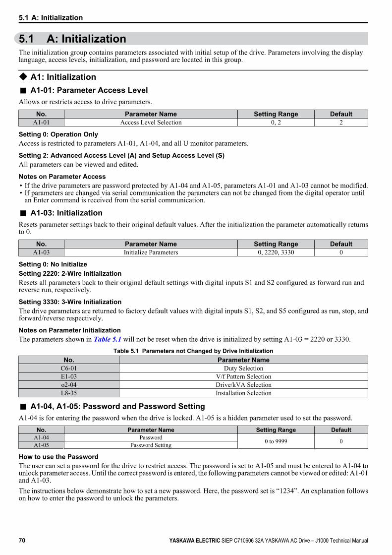
5.1 A: InitializationThe initialization group contains parameters associated with initial setup of the drive. Parameters involving the displaylanguage, access levels, initialization, and password are located in this group.
u A1: Initializationn A1-01: Parameter Access LevelAllows or restricts access to drive parameters.
No. Parameter Name Setting Range DefaultA1-01 Access Level Selection 0, 2 2
Setting 0: Operation OnlyAccess is restricted to parameters A1-01, A1-04, and all U monitor parameters.
Setting 2: Advanced Access Level (A) and Setup Access Level (S)All parameters can be viewed and edited.
Notes on Parameter Access• If the drive parameters are password protected by A1-04 and A1-05, parameters A1-01 and A1-03 cannot be modified.• If parameters are changed via serial communication the parameters can not be changed from the digital operator until
an Enter command is received from the serial communication.
n A1-03: InitializationResets parameter settings back to their original default values. After the initialization the parameter automatically returnsto 0.
No. Parameter Name Setting Range DefaultA1-03 Initialize Parameters 0, 2220, 3330 0
Setting 0: No InitializeSetting 2220: 2-Wire InitializationResets all parameters back to their original default settings with digital inputs S1 and S2 configured as forward run andreverse run, respectively.
Setting 3330: 3-Wire InitializationThe drive parameters are returned to factory default values with digital inputs S1, S2, and S5 configured as run, stop, andforward/reverse respectively.
Notes on Parameter InitializationThe parameters shown in Table 5.1 will not be reset when the drive is initialized by setting A1-03 = 2220 or 3330.
Table 5.1 Parameters not Changed by Drive InitializationNo. Parameter Name
C6-01 Duty SelectionE1-03 V/f Pattern Selectiono2-04 Drive/kVA SelectionL8-35 Installation Selection
n A1-04, A1-05: Password and Password SettingA1-04 is for entering the password when the drive is locked. A1-05 is a hidden parameter used to set the password.
No. Parameter Name Setting Range DefaultA1-04 Password 0 to 9999 0A1-05 Password Setting
How to use the PasswordThe user can set a password for the drive to restrict access. The password is set to A1-05 and must be entered to A1-04 tounlock parameter access. Until the correct password is entered, the following parameters cannot be viewed or edited: A1-01and A1-03.The instructions below demonstrate how to set a new password. Here, the password set is “1234”. An explanation followson how to enter the password to unlock the parameters.
5.1 A: Initialization
70 YASKAWA ELECTRIC SIEP C710606 32A YASKAWA AC Drive – J1000 Technical Manual
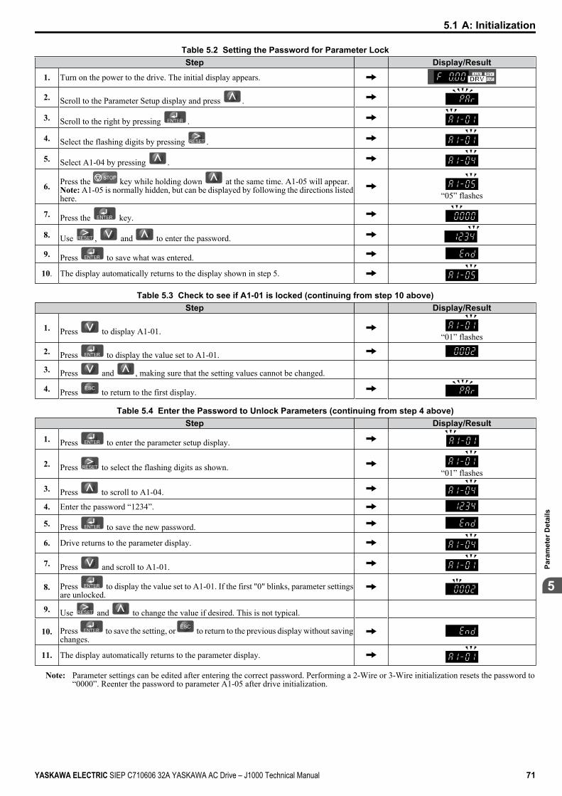
Table 5.2 Setting the Password for Parameter LockStep Display/Result
1. Turn on the power to the drive. The initial display appears.
2. Scroll to the Parameter Setup display and press .
3. Scroll to the right by pressing .
4. Select the flashing digits by pressing .
5. Select A1-04 by pressing .
6. Press the key while holding down at the same time. A1-05 will appear.Note: A1-05 is normally hidden, but can be displayed by following the directions listedhere. “05” flashes
7. Press the key.
8. Use , and to enter the password.
9. Press to save what was entered.
10. The display automatically returns to the display shown in step 5.
Table 5.3 Check to see if A1-01 is locked (continuing from step 10 above)Step Display/Result
1. Press to display A1-01. “01” flashes
2. Press to display the value set to A1-01.
3. Press and , making sure that the setting values cannot be changed.
4. Press to return to the first display.
Table 5.4 Enter the Password to Unlock Parameters (continuing from step 4 above)Step Display/Result
1. Press to enter the parameter setup display.
2. Press to select the flashing digits as shown. “01” flashes
3. Press to scroll to A1-04.
4. Enter the password “1234”.
5. Press to save the new password.
6. Drive returns to the parameter display.
7. Press and scroll to A1-01.
8. Press to display the value set to A1-01. If the first "0" blinks, parameter settingsare unlocked.
9. Use and to change the value if desired. This is not typical.
10. Press to save the setting, or to return to the previous display without savingchanges.
11. The display automatically returns to the parameter display.
Note: Parameter settings can be edited after entering the correct password. Performing a 2-Wire or 3-Wire initialization resets the password to“0000”. Reenter the password to parameter A1-05 after drive initialization.
5.1 A: Initialization
YASKAWA ELECTRIC SIEP C710606 32A YASKAWA AC Drive – J1000 Technical Manual 71
5
Para
met
er D
etai
ls
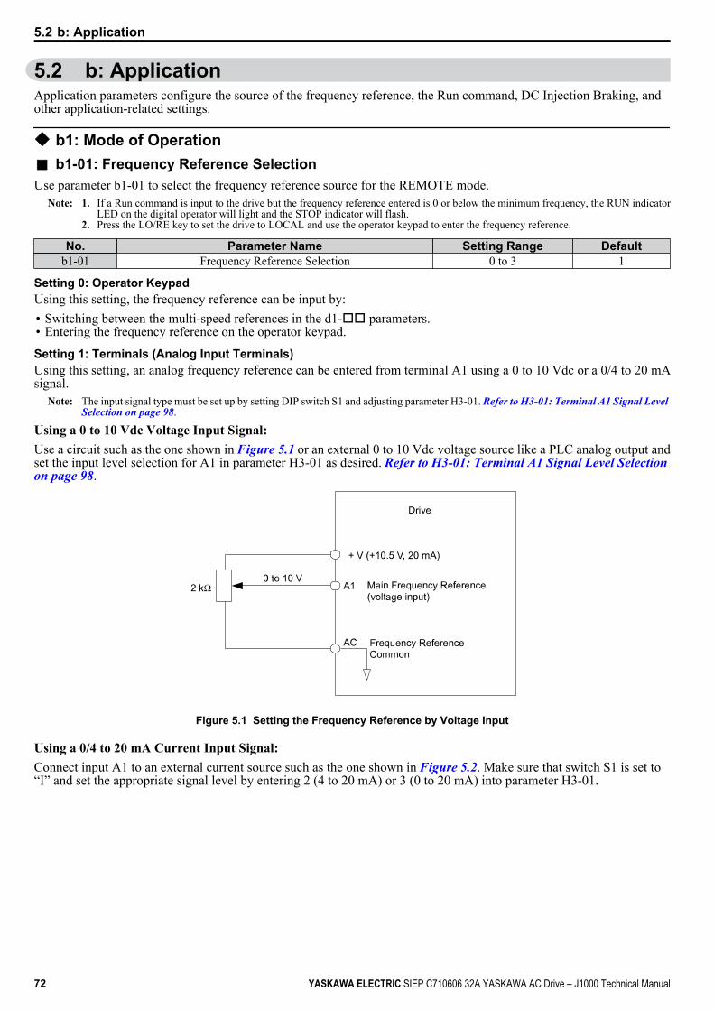
5.2 b: ApplicationApplication parameters configure the source of the frequency reference, the Run command, DC Injection Braking, andother application-related settings.
u b1: Mode of Operationn b1-01: Frequency Reference SelectionUse parameter b1-01 to select the frequency reference source for the REMOTE mode.
Note: 1. If a Run command is input to the drive but the frequency reference entered is 0 or below the minimum frequency, the RUN indicatorLED on the digital operator will light and the STOP indicator will flash.
2. Press the LO/RE key to set the drive to LOCAL and use the operator keypad to enter the frequency reference.
No. Parameter Name Setting Range Defaultb1-01 Frequency Reference Selection 0 to 3 1
Setting 0: Operator KeypadUsing this setting, the frequency reference can be input by:• Switching between the multi-speed references in the d1-oo parameters.• Entering the frequency reference on the operator keypad.
Setting 1: Terminals (Analog Input Terminals)Using this setting, an analog frequency reference can be entered from terminal A1 using a 0 to 10 Vdc or a 0/4 to 20 mAsignal.
Note: The input signal type must be set up by setting DIP switch S1 and adjusting parameter H3-01. Refer to H3-01: Terminal A1 Signal Level Selection on page 98.
Using a 0 to 10 Vdc Voltage Input Signal:Use a circuit such as the one shown in Figure 5.1 or an external 0 to 10 Vdc voltage source like a PLC analog output andset the input level selection for A1 in parameter H3-01 as desired. Refer to H3-01: Terminal A1 Signal Level Selection on page 98.
Figure 5.1 Setting the Frequency Reference by Voltage Input
Using a 0/4 to 20 mA Current Input Signal:Connect input A1 to an external current source such as the one shown in Figure 5.2. Make sure that switch S1 is set to“I” and set the appropriate signal level by entering 2 (4 to 20 mA) or 3 (0 to 20 mA) into parameter H3-01.
5.2 b: Application
72 YASKAWA ELECTRIC SIEP C710606 32A YASKAWA AC Drive – J1000 Technical Manual
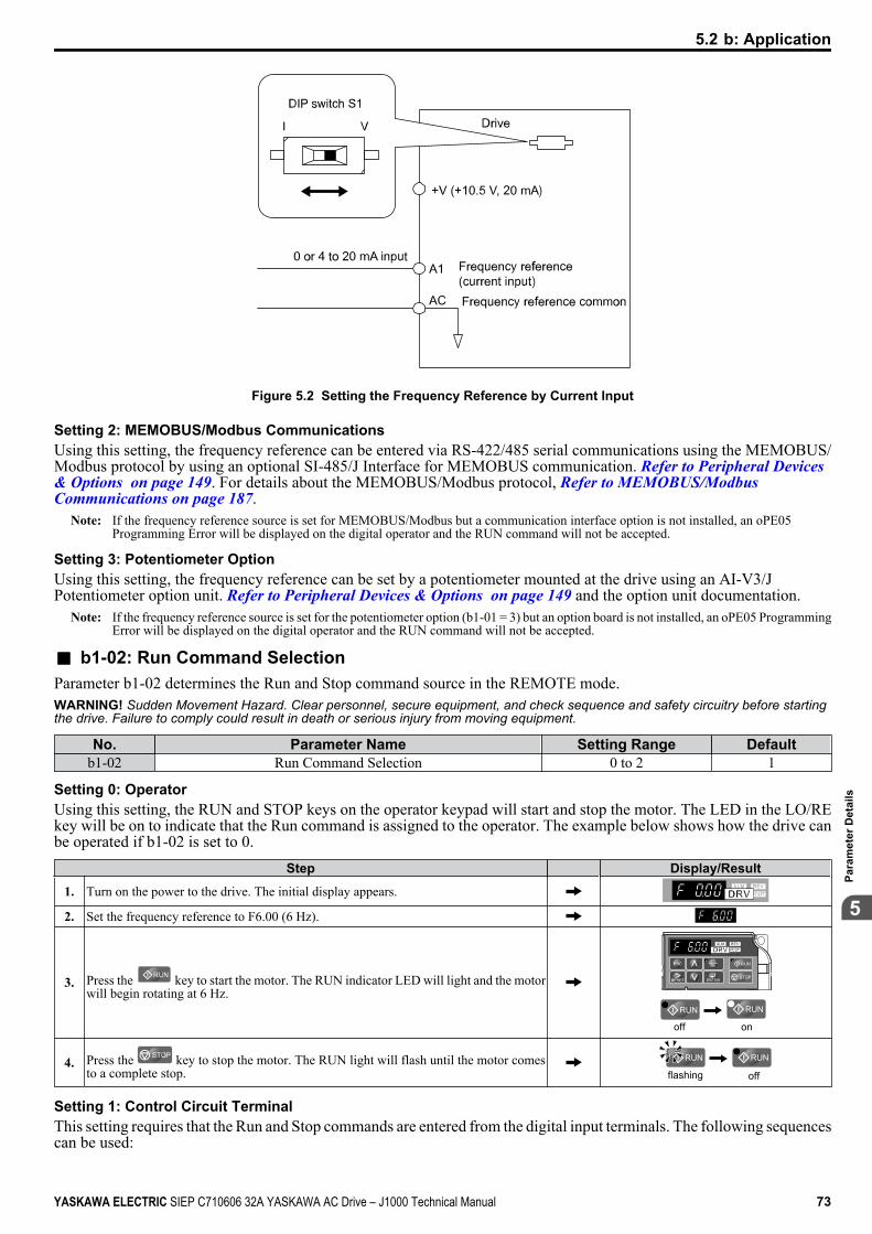
Figure 5.2 Setting the Frequency Reference by Current Input
Setting 2: MEMOBUS/Modbus CommunicationsUsing this setting, the frequency reference can be entered via RS-422/485 serial communications using the MEMOBUS/Modbus protocol by using an optional SI-485/J Interface for MEMOBUS communication. Refer to Peripheral Devices & Options on page 149. For details about the MEMOBUS/Modbus protocol, Refer to MEMOBUS/Modbus Communications on page 187.
Note: If the frequency reference source is set for MEMOBUS/Modbus but a communication interface option is not installed, an oPE05Programming Error will be displayed on the digital operator and the RUN command will not be accepted.
Setting 3: Potentiometer OptionUsing this setting, the frequency reference can be set by a potentiometer mounted at the drive using an AI-V3/JPotentiometer option unit. Refer to Peripheral Devices & Options on page 149 and the option unit documentation.
Note: If the frequency reference source is set for the potentiometer option (b1-01 = 3) but an option board is not installed, an oPE05 ProgrammingError will be displayed on the digital operator and the RUN command will not be accepted.
n b1-02: Run Command SelectionParameter b1-02 determines the Run and Stop command source in the REMOTE mode.WARNING! Sudden Movement Hazard. Clear personnel, secure equipment, and check sequence and safety circuitry before startingthe drive. Failure to comply could result in death or serious injury from moving equipment.
No. Parameter Name Setting Range Defaultb1-02 Run Command Selection 0 to 2 1
Setting 0: OperatorUsing this setting, the RUN and STOP keys on the operator keypad will start and stop the motor. The LED in the LO/REkey will be on to indicate that the Run command is assigned to the operator. The example below shows how the drive canbe operated if b1-02 is set to 0.
Step Display/Result
1. Turn on the power to the drive. The initial display appears.
2. Set the frequency reference to F6.00 (6 Hz).
3. Press the key to start the motor. The RUN indicator LED will light and the motorwill begin rotating at 6 Hz.
STOP
off on
4. Press the key to stop the motor. The RUN light will flash until the motor comesto a complete stop. flashing off
Setting 1: Control Circuit TerminalThis setting requires that the Run and Stop commands are entered from the digital input terminals. The following sequencescan be used:
5.2 b: Application
YASKAWA ELECTRIC SIEP C710606 32A YASKAWA AC Drive – J1000 Technical Manual 73
5
Para
met
er D
etai
ls
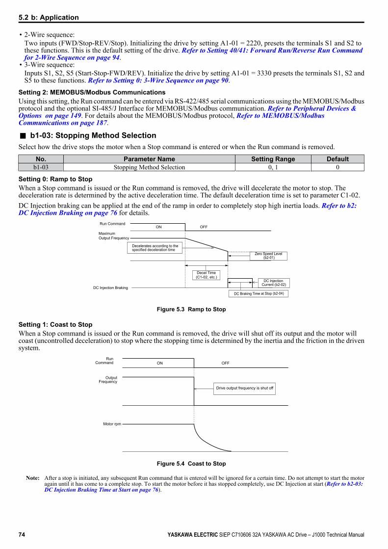
• 2-Wire sequence:Two inputs (FWD/Stop-REV/Stop). Initializing the drive by setting A1-01 = 2220, presets the terminals S1 and S2 tothese functions. This is the default setting of the drive. Refer to Setting 40/41: Forward Run/Reverse Run Command for 2-Wire Sequence on page 94.
• 3-Wire sequence:Inputs S1, S2, S5 (Start-Stop-FWD/REV). Initialize the drive by setting A1-01 = 3330 presets the terminals S1, S2 andS5 to these functions. Refer to Setting 0: 3-Wire Sequence on page 90.
Setting 2: MEMOBUS/Modbus CommunicationsUsing this setting, the Run command can be entered via RS-422/485 serial communications using the MEMOBUS/Modbusprotocol and the optional SI-485/J Interface for MEMOBUS/Modbus communication. Refer to Peripheral Devices & Options on page 149. For details about the MEMOBUS/Modbus protocol, Refer to MEMOBUS/Modbus Communications on page 187.
n b1-03: Stopping Method SelectionSelect how the drive stops the motor when a Stop command is entered or when the Run command is removed.
No. Parameter Name Setting Range Defaultb1-03 Stopping Method Selection 0, 1 0
Setting 0: Ramp to StopWhen a Stop command is issued or the Run command is removed, the drive will decelerate the motor to stop. Thedeceleration rate is determined by the active deceleration time. The default deceleration time is set to parameter C1-02.DC Injection braking can be applied at the end of the ramp in order to completely stop high inertia loads. Refer to b2: DC Injection Braking on page 76 for details.
Run Command
Decelerates according to the specified deceleration time
Zero Speed Level (b2-01)
DC Injection Current (b2-02)
DC Braking Time at Stop (b2-04)
Decel Time(C1-02, etc.)
MaximumOutput Frequency
DC Injection Braking
ON OFF
Figure 5.3 Ramp to Stop
Setting 1: Coast to StopWhen a Stop command is issued or the Run command is removed, the drive will shut off its output and the motor willcoast (uncontrolled deceleration) to stop where the stopping time is determined by the inertia and the friction in the drivensystem.
Drive output frequency is shut off
Run Command
Output Frequency
Motor rpm
ON OFF
Figure 5.4 Coast to Stop
Note: After a stop is initiated, any subsequent Run command that is entered will be ignored for a certain time. Do not attempt to start the motoragain until it has come to a complete stop. To start the motor before it has stopped completely, use DC Injection at start (Refer to b2-03: DC Injection Braking Time at Start on page 76).
5.2 b: Application
74 YASKAWA ELECTRIC SIEP C710606 32A YASKAWA AC Drive – J1000 Technical Manual
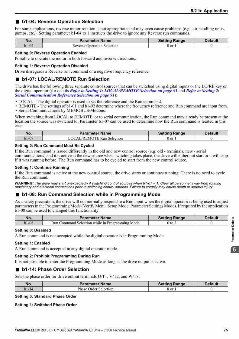
n b1-04: Reverse Operation SelectionFor some applications, reverse motor rotation is not appropriate and may even cause problems (e.g., air handling units,pumps, etc.). Setting parameter b1-04 to 1 instructs the drive to ignore any Reverse run commands.
No. Parameter Name Setting Range Defaultb1-04 Reverse Operation Selection 0 or 1 0
Setting 0: Reverse Operation EnabledPossible to operate the motor in both forward and reverse directions.
Setting 1: Reverse Operation DisabledDrive disregards a Reverse run command or a negative frequency reference.
n b1-07: LOCAL/REMOTE Run SelectionThe drive has the following three separate control sources that can be switched using digital inputs or the LO/RE key onthe digital operator (for details Refer to Setting 1: LOCAL/REMOTE Selection on page 91 and Refer to Setting 2: Serial Communication Reference Selection on page 91):• LOCAL - The digital operator is used to set the reference and the Run command.• REMOTE - The settings of b1-01 and b1-02 determine where the frequency reference and Run command are input from.• Serial Communications by MEMOBUS/Modbus.When switching from LOCAL to REMOTE, or to serial communication, the Run command may already be present at thelocation the source was switched to. Parameter b1-07 can be used to determine how the Run command is treated in thiscase.
No. Parameter Name Setting Range Defaultb1-07 LOCAL/REMOTE Run Selection 0 or 1 0
Setting 0: Run Command Must Be CycledIf the Run command is issued differently in the old and new control source (e.g. old - terminals, new - serialcommunications) and it is active at the new source when switching takes place, the drive will either not start or it will stopif it was running before. The Run command has to be cycled to start from the new control source.
Setting 1: Continue RunningIf the Run command is active at the new control source, the drive starts or continues running. There is no need to cyclethe Run command.WARNING! The drive may start unexpectedly if switching control sources when b1-07 = 1. Clear all personnel away from rotatingmachinery and electrical connections prior to switching control sources. Failure to comply may cause death or serious injury.
n b1-08: Run Command Selection while in Programming ModeAs a safety precaution, the drive will not normally respond to a Run input when the digital operator is being used to adjustparameters in the Programming Mode (Verify Menu, Setup Mode, Parameter Settings Mode). If required by the applicationb1-08 can be used to changed this functionality.
No. Parameter Name Setting Range Defaultb1-08 Run Command Selection while in Programming Mode 0 to 2 0
Setting 0: DisabledA Run command is not accepted while the digital operator is in Programming Mode.
Setting 1: EnabledA Run command is accepted in any digital operator mode.
Setting 2: Prohibit Programming During RunIt is not possible to enter the Programming Mode as long as the drive output is active.
n b1-14: Phase Order SelectionSets the phase order for drive output terminals U/T1, V/T2, and W/T3.
No. Parameter Name Setting Range Defaultb1-14 Phase Order Selection 0 or 1 0
Setting 0: Standard Phase Order
Setting 1: Switched Phase Order
5.2 b: Application
YASKAWA ELECTRIC SIEP C710606 32A YASKAWA AC Drive – J1000 Technical Manual 75
5
Para
met
er D
etai
ls
n b1-17: Run Command at Power UpThis parameter is used to determine whether an external Run command that is active during power up of the drive willstart the drive or not.
No. Parameter Name Setting Range Defaultb1-17 Run Command at Power Up 0 or 1 0
Setting 0: Run Command at Power Up is not IssuedThe Run command has to be cycled to start the drive.
Note: For safety reasons, the drive is initially set up not to accept a Run command at power up (b1-17 = "0"). If a Run command is issued atpower up, the RUN indicator LED will flash quickly. Change parameter b1-17 to 1 if a Run command active at power up shall be acceptedby the drive.
Setting 1: Run Command and Power Up is IssuedAn external Run command active during power up is issued and the drive starts to operate the motor as soon as it getsready for operation (i.e. once the internal start up process is complete).WARNING! Sudden Movement Hazard. If b1-17 is set to 1 and an external Run command is active during power up, the motor willbegin rotating as soon as the power is switched on. Proper precautions must be taken to ensure that the area around the motor is safeprior to powering up the drive. Failure to comply may cause serious injury.
u b2: DC Injection BrakingThese parameters determine how the DC Injection Braking feature operates. Parameters involving the starting frequency,current level, braking time are located here.
n b2-02: DC Injection Braking CurrentSets the DC Injection Braking current as a percentage of the drive rated current. If set to larger than 50%, the carrierfrequency is automatically reduced to 1 kHz.
No. Name Setting Range Defaultb2-02 DC Injection Braking Current 0 to 75% 50%
The level of DC Injection Braking current affects the strength of the magnetic field attempting to lock the motor shaft.Increasing the current level will increase the amount of heat generated by the motor windings. This parameter should onlybe increased to the level necessary to hold the motor shaft.
n b2-03: DC Injection Braking Time at StartSets the time of DC Injection Braking at start. It can be used to stop a coasting motor before restarting it or to apply abraking torque at start. Disabled when set to 0.00 s.
No. Name Setting Range Defaultb2-03 DC Injection Braking Time at Start 0.00 to 10.00 s 0.50 s
Note: Before starting an uncontrolled rotating motor (e.g. a fan motor driven by windmill effect), use DC Injection to stop the motor beforestarting it. Otherwise motor stalling and other faults can occur.
n b2-04: DC Injection Braking Time at StopWhen the output frequency falls below the minimum output frequency setting E1-09, the drive applies DC injection forthe time set in b2-04. Used to completely stop a motor with high inertia load after ramp down. Increase the setting if themotor tends to coast by inertia after a stop.
No. Name Setting Range Defaultb2-04 DC Injection Braking Time at Stop 0.00 to 10.00 s 0.50 s
5.2 b: Application
76 YASKAWA ELECTRIC SIEP C710606 32A YASKAWA AC Drive – J1000 Technical Manual
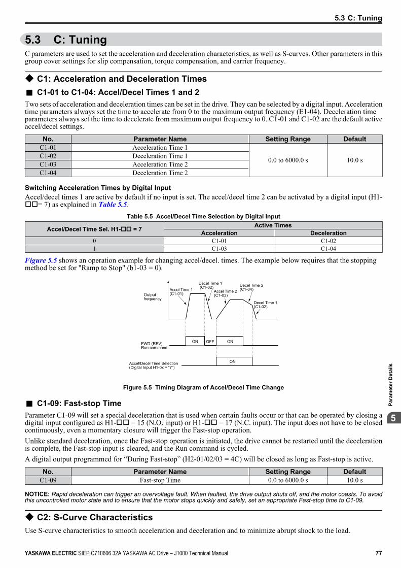
5.3 C: TuningC parameters are used to set the acceleration and deceleration characteristics, as well as S-curves. Other parameters in thisgroup cover settings for slip compensation, torque compensation, and carrier frequency.
u C1: Acceleration and Deceleration Timesn C1-01 to C1-04: Accel/Decel Times 1 and 2Two sets of acceleration and deceleration times can be set in the drive. They can be selected by a digital input. Accelerationtime parameters always set the time to accelerate from 0 to the maximum output frequency (E1-04). Deceleration timeparameters always set the time to decelerate from maximum output frequency to 0. C1-01 and C1-02 are the default activeaccel/decel settings.
No. Parameter Name Setting Range DefaultC1-01 Acceleration Time 1
0.0 to 6000.0 s 10.0 sC1-02 Deceleration Time 1C1-03 Acceleration Time 2C1-04 Deceleration Time 2
Switching Acceleration Times by Digital InputAccel/decel times 1 are active by default if no input is set. The accel/decel time 2 can be activated by a digital input (H1-oo= 7) as explained in Table 5.5.
Table 5.5 Accel/Decel Time Selection by Digital Input
Accel/Decel Time Sel. H1-oo = 7 Active TimesAcceleration Deceleration
0 C1-01 C1-021 C1-03 C1-04
Figure 5.5 shows an operation example for changing accel/decel. times. The example below requires that the stoppingmethod be set for "Ramp to Stop" (b1-03 = 0).
Outputfrequency
Accel Time 1(C1-01)
Decel Time 1 (C1-02)
Accel Time 2 (C1-03)
Decel Time 2(C1-04)
Decel Time 1(C1-02)
FWD (REV) Run command
ON OFF ON
ONAccel/Decel Time Selection(Digital Input H1-0x = “7”)
Figure 5.5 Timing Diagram of Accel/Decel Time Change
n C1-09: Fast-stop TimeParameter C1-09 will set a special deceleration that is used when certain faults occur or that can be operated by closing adigital input configured as H1-oo = 15 (N.O. input) or H1-oo = 17 (N.C. input). The input does not have to be closedcontinuously, even a momentary closure will trigger the Fast-stop operation.Unlike standard deceleration, once the Fast-stop operation is initiated, the drive cannot be restarted until the decelerationis complete, the Fast-stop input is cleared, and the Run command is cycled.A digital output programmed for “During Fast-stop” (H2-01/02/03 = 4C) will be closed as long as Fast-stop is active.
No. Parameter Name Setting Range DefaultC1-09 Fast-stop Time 0.0 to 6000.0 s 10.0 s
NOTICE: Rapid deceleration can trigger an overvoltage fault. When faulted, the drive output shuts off, and the motor coasts. To avoidthis uncontrolled motor state and to ensure that the motor stops quickly and safely, set an appropriate Fast-stop time to C1-09.
u C2: S-Curve CharacteristicsUse S-curve characteristics to smooth acceleration and deceleration and to minimize abrupt shock to the load.
5.3 C: Tuning
YASKAWA ELECTRIC SIEP C710606 32A YASKAWA AC Drive – J1000 Technical Manual 77
5
Para
met
er D
etai
ls
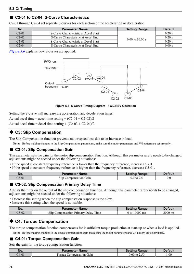
n C2-01 to C2-04: S-Curve CharacteristicsC2-01 through C2-04 set separate S-curves for each section of the acceleration or deceleration.
No. Parameter Name Setting Range DefaultC2-01 S-Curve Characteristic at Accel Start
0.00 to 10.00 s
0.20 sC2-02 S-Curve Characteristic at Accel End 0.20 sC2-03 S-Curve Characteristic at Decel Start 0.20 sC2-04 S-Curve Characteristic at Decel End 0.00 s
Figure 5.6 explains how S-curves are applied.
C2-02
C2-01
C2-03 C2-04
C2-02
C2-01
C2-03
C2-04
FWD run
REV run
Outputfrequency
Figure 5.6 S-Curve Timing Diagram - FWD/REV Operation
Setting the S-curve will increase the acceleration and deceleration times.Actual accel time = accel time setting + (C2-01 + C2-02)/2Actual decel time = decel time setting + (C2-03 + C2-04)/2
u C3: Slip CompensationThe Slip Compensation function prevents motor speed loss due to an increase in load.
Note: Before making changes to the Slip Compensation parameters, make sure the motor parameters and V/f pattern are set properly.
n C3-01: Slip Compensation GainThis parameter sets the gain for the motor slip compensation function. Although this parameter rarely needs to be changed,adjustments might be needed under the following situations:• If the speed at constant frequency reference is lower than the frequency reference, increase C3-01.• If the speed at constant frequency reference is higher than the frequency reference, decrease C3-01.
No. Parameter Name Setting Range DefaultC3-01 Slip Compensation Gain 0.0 to 2.5 0.0
n C3-02: Slip Compensation Primary Delay TimeAdjusts the filter on the output of the slip compensation function. Although this parameter rarely needs to be changed,adjustments might be needed under the following situations:• Decrease the setting when the slip compensation response is too slow.• Increase this setting when the speed is not stable.
No. Parameter Name Setting Range DefaultC3-02 Slip Compensation Primary Delay Time 0 to 10000 ms 2000 ms
u C4: Torque CompensationThe torque compensation function compensates for insufficient torque production at start-up or when a load is applied.
Note: Before making changes to the torque compensation gain make sure the motor parameters and V/f pattern are set properly.
n C4-01: Torque Compensation GainSets the gain for the torque compensation function.
No. Parameter Name Setting Range DefaultC4-01 Torque Compensation Gain 0.00 to 2.50 1.00
5.3 C: Tuning
78 YASKAWA ELECTRIC SIEP C710606 32A YASKAWA AC Drive – J1000 Technical Manual
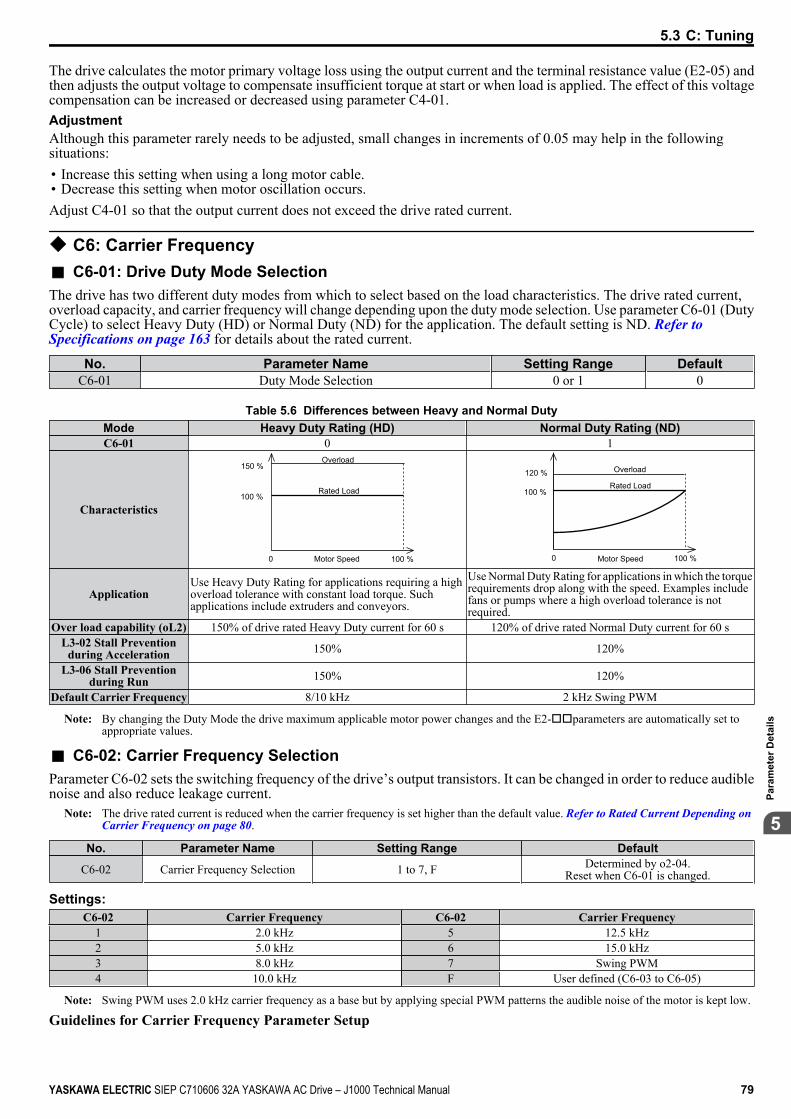
The drive calculates the motor primary voltage loss using the output current and the terminal resistance value (E2-05) andthen adjusts the output voltage to compensate insufficient torque at start or when load is applied. The effect of this voltagecompensation can be increased or decreased using parameter C4-01.AdjustmentAlthough this parameter rarely needs to be adjusted, small changes in increments of 0.05 may help in the followingsituations:• Increase this setting when using a long motor cable.• Decrease this setting when motor oscillation occurs.Adjust C4-01 so that the output current does not exceed the drive rated current.
u C6: Carrier Frequencyn C6-01: Drive Duty Mode SelectionThe drive has two different duty modes from which to select based on the load characteristics. The drive rated current,overload capacity, and carrier frequency will change depending upon the duty mode selection. Use parameter C6-01 (DutyCycle) to select Heavy Duty (HD) or Normal Duty (ND) for the application. The default setting is ND. Refer to Specifications on page 163 for details about the rated current.
No. Parameter Name Setting Range DefaultC6-01 Duty Mode Selection 0 or 1 0
Table 5.6 Differences between Heavy and Normal DutyMode Heavy Duty Rating (HD) Normal Duty Rating (ND)C6-01 0 1
Characteristics100 %
100 %0 Motor Speed
Rated Load
Overload150 %
Motor Speed0
100 %
100 %
120 %Rated Load
Overload
ApplicationUse Heavy Duty Rating for applications requiring a highoverload tolerance with constant load torque. Suchapplications include extruders and conveyors.
Use Normal Duty Rating for applications in which the torquerequirements drop along with the speed. Examples includefans or pumps where a high overload tolerance is notrequired.
Over load capability (oL2) 150% of drive rated Heavy Duty current for 60 s 120% of drive rated Normal Duty current for 60 sL3-02 Stall Prevention
during Acceleration 150% 120%
L3-06 Stall Preventionduring Run 150% 120%
Default Carrier Frequency 8/10 kHz 2 kHz Swing PWM
Note: By changing the Duty Mode the drive maximum applicable motor power changes and the E2-ooparameters are automatically set toappropriate values.
n C6-02: Carrier Frequency SelectionParameter C6-02 sets the switching frequency of the drive’s output transistors. It can be changed in order to reduce audiblenoise and also reduce leakage current.
Note: The drive rated current is reduced when the carrier frequency is set higher than the default value. Refer to Rated Current Depending on Carrier Frequency on page 80.
No. Parameter Name Setting Range Default
C6-02 Carrier Frequency Selection 1 to 7, F Determined by o2-04.Reset when C6-01 is changed.
Settings:C6-02 Carrier Frequency C6-02 Carrier Frequency
1 2.0 kHz 5 12.5 kHz2 5.0 kHz 6 15.0 kHz3 8.0 kHz 7 Swing PWM4 10.0 kHz F User defined (C6-03 to C6-05)
Note: Swing PWM uses 2.0 kHz carrier frequency as a base but by applying special PWM patterns the audible noise of the motor is kept low.
Guidelines for Carrier Frequency Parameter Setup
5.3 C: Tuning
YASKAWA ELECTRIC SIEP C710606 32A YASKAWA AC Drive – J1000 Technical Manual 79
5
Para
met
er D
etai
ls
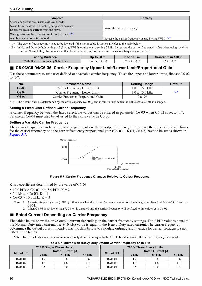
Symptom RemedySpeed and torque are unstable at low speeds.
Lower the carrier frequency.Noise from the drive is affecting peripheral devices.Excessive leakage current from the drive.Wiring between the drive and motor is too long. <1>
Audible motor noise is too loud. Increase the carrier frequency or use Swing PWM. <2>
<1> The carrier frequency may need to be lowered if the motor cable is too long. Refer to the table below.<2> In Normal Duty default setting is 7 (Swing PWM), equivalent to setting 2 kHz. Increasing the carrier frequency is fine when using the drive
is set for Normal Duty, but remember that the drive rated current falls when the carrier frequency is increased.
Wiring Distance Up to 50 m Up to 100 m Greater than 100 mC6-02 (Carrier Frequency Selection) 1 to F (15 kHz) 1, 2 (5 kHz), 7 1 (2 kHz), 7
n C6-03/C6-04/C6-05: Carrier Frequency Upper Limit/Lower Limit/Proportional GainUse these parameters to set a user defined or a variable carrier frequency. To set the upper and lower limits, first set C6-02to “F”.
No. Parameter Name Setting Range DefaultC6-03 Carrier Frequency Upper Limit 1.0 to 15.0 kHz
<1>C6-04 Carrier Frequency Lower Limit 1.0 to 15.0 kHzC6-05 Carrier Frequency Proportional Gain 0 to 99
<1> The default value is determined by the drive capacity (o2-04), and is reinitialized when the value set to C6-01 is changed.
Setting a Fixed User Defined Carrier FrequencyA carrier frequency between the fixed selectable values can be entered in parameter C6-03 when C6-02 is set to “F”.Parameter C6-04 must also be adjusted to the same value as C6-03.
Setting a Variable Carrier FrequencyThe carrier frequency can be set up to change linearly with the output frequency. In this case the upper and lower limitsfor the carrier frequency and the carrier frequency proportional gain (C6-03, C6-04, C6-05) have to be set as shown inFigure 5.7.
C6-03
C6-04
E1-04
x C6-05 x K*
Output Frequency
OutputFrequency
Max Output Frequency
Carrier Frequency
Figure 5.7 Carrier Frequency Changes Relative to Output Frequency
K is a coefficient determined by the value of C6-03:• 10.0 kHz > C6-03 ≥ to 5.0 kHz: K = 2• 5.0 kHz > C6-03: K = 1• C6-03 ≥ 10.0 kHz: K = 3
Note: 1. A carrier frequency error (oPE11) will occur when the carrier frequency proportional gain is greater than 6 while C6-03 is less thanC6-04.
2. When C6-05 is set lower than 7, C6-04 is disabled and the carrier frequency will be fixed to the value set in C6-03.
n Rated Current Depending on Carrier FrequencyThe tables below show the drive output current depending on the carrier frequency settings. The 2 kHz value is equal tothe Normal Duty rated current, the 8/10 kHz value is equal to the Heavy Duty rated current. The carrier frequencydetermines the output current linearly. Use the data below to calculate output current values for carrier frequencies notlisted in the tables.
Note: In Heavy Duty mode the maximum rated output current is equal to the 8/10 kHz value, even if the carrier frequency is reduced.
Table 5.7 Drives with Heavy Duty Default Carrier Frequency of 10 kHz200 V Single Phase Units 200 V Three Phase Units
Model Jo Rated Current [A] Model Jo Rated Current [A]2 kHz 10 kHz 15 kHz 2 kHz 10 kHz 15 kHz
BA0001 1.2 0.8 0.6 BA0001 1.2 0.8 0.6BA0002 1.9 1.6 1.3 BA0002 1.9 1.6 1.3BA0003 3.5 3.0 2.4 BA0004 3.5 3.0 2.4
5.3 C: Tuning
80 YASKAWA ELECTRIC SIEP C710606 32A YASKAWA AC Drive – J1000 Technical Manual
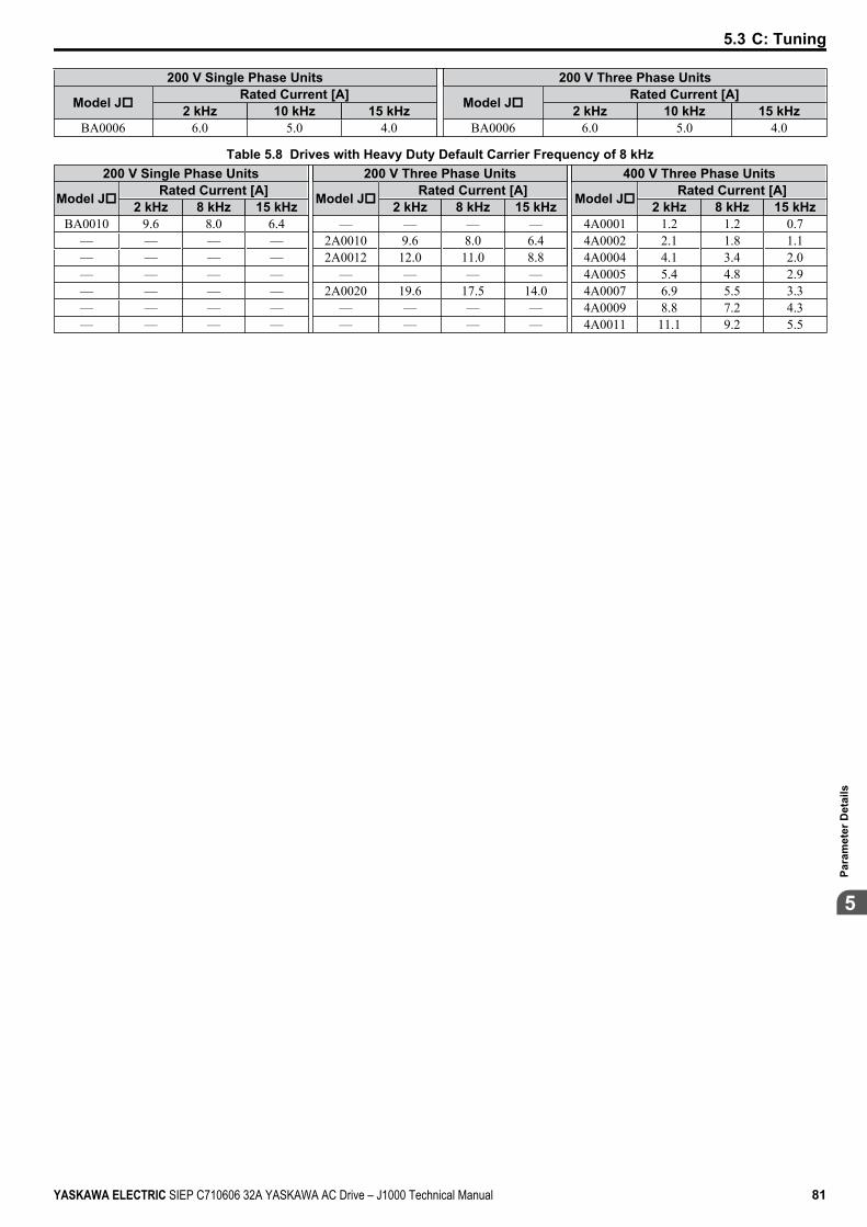
200 V Single Phase Units 200 V Three Phase Units
Model Jo Rated Current [A] Model Jo Rated Current [A]2 kHz 10 kHz 15 kHz 2 kHz 10 kHz 15 kHz
BA0006 6.0 5.0 4.0 BA0006 6.0 5.0 4.0
Table 5.8 Drives with Heavy Duty Default Carrier Frequency of 8 kHz200 V Single Phase Units 200 V Three Phase Units 400 V Three Phase Units
Model Jo Rated Current [A] Model Jo Rated Current [A] Model Jo Rated Current [A]2 kHz 8 kHz 15 kHz 2 kHz 8 kHz 15 kHz 2 kHz 8 kHz 15 kHz
BA0010 9.6 8.0 6.4 — — — — 4A0001 1.2 1.2 0.7— — — — 2A0010 9.6 8.0 6.4 4A0002 2.1 1.8 1.1— — — — 2A0012 12.0 11.0 8.8 4A0004 4.1 3.4 2.0— — — — — — — — 4A0005 5.4 4.8 2.9— — — — 2A0020 19.6 17.5 14.0 4A0007 6.9 5.5 3.3— — — — — — — — 4A0009 8.8 7.2 4.3— — — — — — — — 4A0011 11.1 9.2 5.5
5.3 C: Tuning
YASKAWA ELECTRIC SIEP C710606 32A YASKAWA AC Drive – J1000 Technical Manual 81
5
Para
met
er D
etai
ls
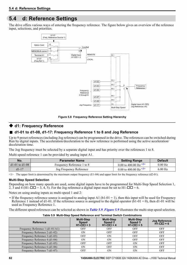
5.4 d: Reference SettingsThe drive offers various ways of entering the frequency reference. The figure below gives an overview of the referenceinput, selections, and priorities.
MS 2
MS 3
MS 4
MS 7
MS 8
Jog
d1-03
d1-04
d1-07
d1-08
d1-17
d1-02
REMOTE
LOCAL
MS 1
01
ComRef=3
=2
=1
=0
0
1
Digital Input H1-oo = 2
MEMOBUS comm.
d1-01(Freq.Ref 1)
b1-01(Freq. Reference Source 1)
Option Card
Digital Input (H1-oo)Jog Reference (=6)
Frequency Reference
2 through 8
Jog FrequencyMulti-Step Speed
Terminal A1
FrequencyReference
Figure 5.8 Frequency Reference Setting Hierarchy
u d1: Frequency Referencen d1-01 to d1-08, d1-17: Frequency Reference 1 to 8 and Jog ReferenceUp to 9 preset references (including Jog reference) can be programmed in the drive. The references can be switched duringRun by digital inputs. The acceleration/deceleration to the new reference is performed using the active acceleration/deceleration time.The Jog frequency must be selected by a separate digital input and has priority over the references 1 to 8.Multi-speed reference 1 can be provided by analog input A1.
No. Parameter Name Setting Range Defaultd1-01 to d1-08 Frequency Reference 1 to 8 0.00 to 400.00 Hz <1> 0.00 Hz
d1-17 Jog Frequency Reference 0.00 to 400.00 Hz <1> 6.00 Hz<1> The upper limit is determined by the maximum output frequency (E1-04) and upper limit for the frequency reference (d2-01).
Multi-Step Speed SelectionDepending on how many speeds are used, some digital inputs have to be programmed for Multi-Step Speed Selection 1,2, 3 and 4 (H1-oo = 3, 4, 5). For the Jog reference a digital input must be set to H1-oo = 6.Notes on using analog inputs as multi-speed 1 and 2:• If the frequency reference source is assigned to analog input A1 (b1-01 = 1), then this input will be used for Frequency
Reference 1 instead of d1-01. If the reference source is assigned to the digital operator (b1-01 = 0), then d1-01 will beused as Frequency Reference 1.
The different speed references can be selected as shown in Table 5.9. Figure 5.9 illustrates the multi-step speed selection.Table 5.9 Multi-Step Speed Reference and Terminal Switch Combinations
ReferenceMulti-Step
SpeedH1-oo = 3
Multi-StepSpeed 2
H1-oo = 4
Multi-StepSpeed 3
H1-oo = 5Jog Reference
H1-oo = 6
Frequency Reference 1 (d1-01/A1) OFF OFF OFF OFFFrequency Reference 2 (d1-02) ON OFF OFF OFFFrequency Reference 3 (d1-03) OFF ON OFF OFFFrequency Reference 4 (d1-04) ON ON OFF OFFFrequency Reference 5 (d1-05) OFF OFF ON OFFFrequency Reference 6 (d1-06) ON OFF ON OFFFrequency Reference 7 (d1-07) OFF ON ON OFF
5.4 d: Reference Settings
82 YASKAWA ELECTRIC SIEP C710606 32A YASKAWA AC Drive – J1000 Technical Manual

ReferenceMulti-Step
SpeedH1-oo = 3
Multi-StepSpeed 2
H1-oo = 4
Multi-StepSpeed 3
H1-oo = 5Jog Reference
H1-oo = 6
Frequency Reference 8 (d1-08) ON ON ON OFFJog Frequency Reference (d1-17) <1> − − − ON
<1> The Jog frequency overrides the frequency reference being used.
d1-04
d1-01d1-02
d1-03
ON
ON
ON
ON
ON
d1-05
d1-06
d1-07
d1-08
d1-17
ON
ON
ON
ON ON
Frequencyreference
Time
Multi-step Speed Ref. 1
Multi-step Speed Ref. 2
Multi-step Speed Ref. 3
Jog Reference
FWD (REV) Run/Stop
(A1)
Figure 5.9 Preset Reference Timing Diagram
u d2: Frequency Upper/Lower LimitsBy entering upper or lower frequency limits, the drive programmer can prevent operation of the drive above or belowlevels that may cause resonance and or equipment damage.
n d2-01: Frequency Reference Upper LimitSets the maximum frequency reference as a percentage of the maximum output frequency. This limit applies to all frequencyreferences.Even if the frequency reference is set to a higher value, the drive internal frequency reference will not exceed this value.
No. Parameter Name Setting Range Defaultd2-01 Frequency Reference Upper Limit 0.0 to 110.0% 100.0%
n d2-02: Frequency Reference Lower LimitSets the minimum frequency reference as a percentage of the maximum output frequency. This limit applies to all frequencyreferences.If a lower reference than this value is input, the drive will run at the d2-02 level. If the drive is started with a lower referencethan d2-02, it will accelerate up to d2-02.
No. Parameter Name Setting Range Defaultd2-02 Frequency Reference Lower Limit 0.0 to 110.0% 0.0%
Internal frequencyreference
d2-01
Operatingrange
Frequency Reference Upper Limit
Set frequency reference
Frequency Reference Lower Limitd2-02
Figure 5.10 Frequency Reference: Upper and Lower Limits
5.4 d: Reference Settings
YASKAWA ELECTRIC SIEP C710606 32A YASKAWA AC Drive – J1000 Technical Manual 83
5
Para
met
er D
etai
ls
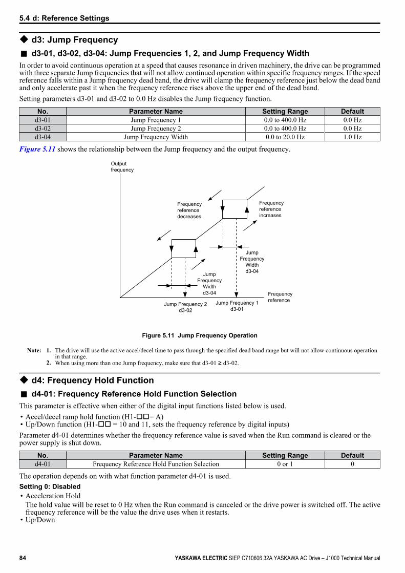
u d3: Jump Frequencyn d3-01, d3-02, d3-04: Jump Frequencies 1, 2, and Jump Frequency WidthIn order to avoid continuous operation at a speed that causes resonance in driven machinery, the drive can be programmedwith three separate Jump frequencies that will not allow continued operation within specific frequency ranges. If the speedreference falls within a Jump frequency dead band, the drive will clamp the frequency reference just below the dead bandand only accelerate past it when the frequency reference rises above the upper end of the dead band.Setting parameters d3-01 and d3-02 to 0.0 Hz disables the Jump frequency function.
No. Parameter Name Setting Range Defaultd3-01 Jump Frequency 1 0.0 to 400.0 Hz 0.0 Hzd3-02 Jump Frequency 2 0.0 to 400.0 Hz 0.0 Hzd3-04 Jump Frequency Width 0.0 to 20.0 Hz 1.0 Hz
Figure 5.11 shows the relationship between the Jump frequency and the output frequency.
Outputfrequency
Frequencyreferencedecreases
Frequencyreferenceincreases
FrequencyreferenceJump Frequency 1
d3-01Jump Frequency 2
d3-02
JumpFrequency
Widthd3-04
JumpFrequency
Widthd3-04
Figure 5.11 Jump Frequency Operation
Note: 1. The drive will use the active accel/decel time to pass through the specified dead band range but will not allow continuous operationin that range.
2. When using more than one Jump frequency, make sure that d3-01 ≥ d3-02.
u d4: Frequency Hold Functionn d4-01: Frequency Reference Hold Function SelectionThis parameter is effective when either of the digital input functions listed below is used.• Accel/decel ramp hold function (H1-oo= A)• Up/Down function (H1-oo = 10 and 11, sets the frequency reference by digital inputs)Parameter d4-01 determines whether the frequency reference value is saved when the Run command is cleared or thepower supply is shut down.
No. Parameter Name Setting Range Defaultd4-01 Frequency Reference Hold Function Selection 0 or 1 0
The operation depends on with what function parameter d4-01 is used.Setting 0: Disabled• Acceleration Hold
The hold value will be reset to 0 Hz when the Run command is canceled or the drive power is switched off. The activefrequency reference will be the value the drive uses when it restarts.
• Up/Down
5.4 d: Reference Settings
84 YASKAWA ELECTRIC SIEP C710606 32A YASKAWA AC Drive – J1000 Technical Manual
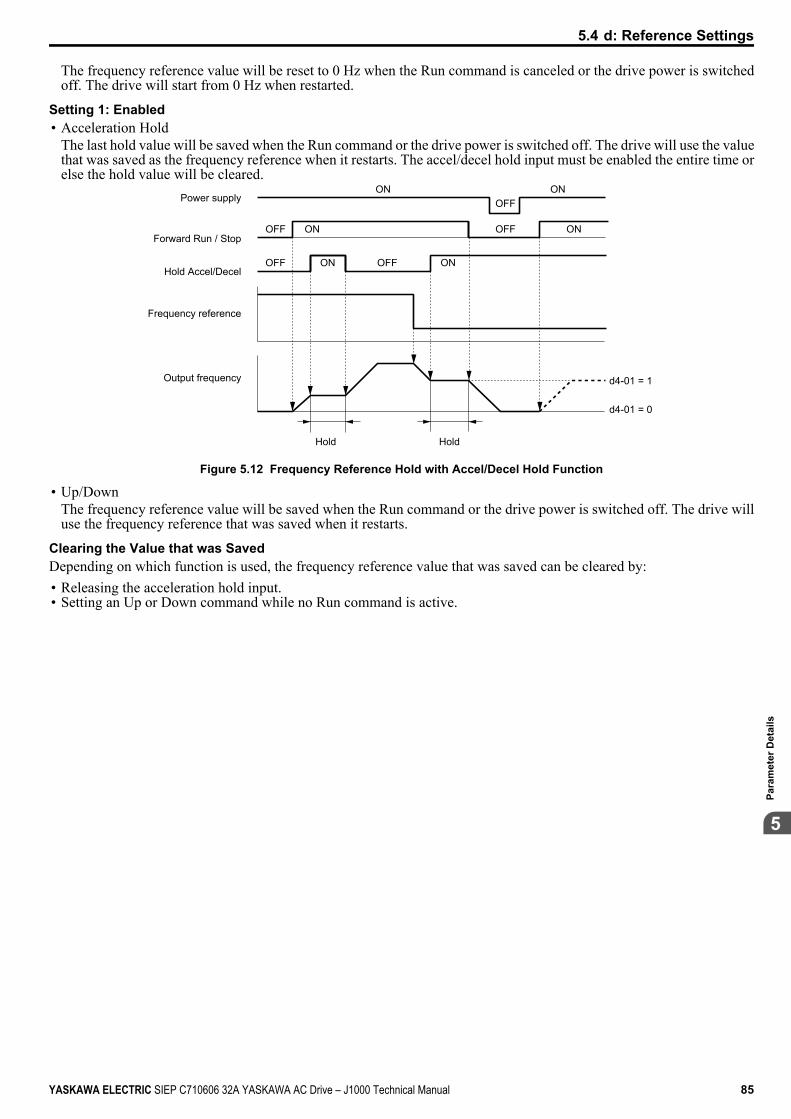
The frequency reference value will be reset to 0 Hz when the Run command is canceled or the drive power is switchedoff. The drive will start from 0 Hz when restarted.
Setting 1: Enabled• Acceleration Hold
The last hold value will be saved when the Run command or the drive power is switched off. The drive will use the valuethat was saved as the frequency reference when it restarts. The accel/decel hold input must be enabled the entire time orelse the hold value will be cleared.
Power supply
Forward Run / Stop
Hold Accel/Decel
Frequency reference
Output frequency d4-01 = 1
d4-01 = 0
Hold Hold
OFF
OFFOFF
OFF OFF
ON
ON ON
ON ON
ON
Figure 5.12 Frequency Reference Hold with Accel/Decel Hold Function
• Up/DownThe frequency reference value will be saved when the Run command or the drive power is switched off. The drive willuse the frequency reference that was saved when it restarts.
Clearing the Value that was SavedDepending on which function is used, the frequency reference value that was saved can be cleared by:• Releasing the acceleration hold input.• Setting an Up or Down command while no Run command is active.
5.4 d: Reference Settings
YASKAWA ELECTRIC SIEP C710606 32A YASKAWA AC Drive – J1000 Technical Manual 85
5
Para
met
er D
etai
ls
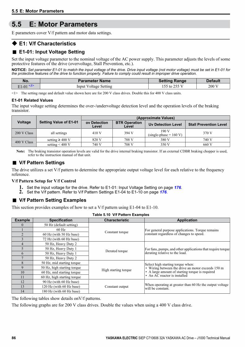
5.5 E: Motor ParametersE parameters cover V/f pattern and motor data settings.
u E1: V/f Characteristicsn E1-01: Input Voltage SettingSet the input voltage parameter to the nominal voltage of the AC power supply. This parameter adjusts the levels of someprotective features of the drive (overvoltage, Stall Prevention, etc.).NOTICE: Set parameter E1-01 to match the input voltage of the drive. Drive input voltage (not motor voltage) must be set in E1-01 forthe protective features of the drive to function properly. Failure to comply could result in improper drive operation.
No. Parameter Name Setting Range DefaultE1-01 <1> Input Voltage Setting 155 to 255 V 200 V
<1> The setting range and default value shown here are for 200 V class drives. Double this for 400 V class units.
E1-01 Related ValuesThe input voltage setting determines the over-/undervoltage detection level and the operation levels of the brakingtransistor.
Voltage Setting Value of E1-01(Approximate Values)
ov DetectionLevel
BTR OperationLevel Uv Detection Level Stall Prevention Level
200 V Class all settings 410 V 394 V 190 V(single-phase = 160 V) 370 V
400 V Class setting ≥ 400 V 820 V 788 V 380 V 740 Vsetting < 400 V 740 V 708 V 350 V 660 V
Note: The braking transistor operation levels are valid for the drive internal braking transistor. If an external CDBR braking chopper is used,refer to the instruction manual of that unit.
n V/f Pattern SettingsThe drive utilizes a set V/f pattern to determine the appropriate output voltage level for each relative to the frequencyreference.V/f Pattern Setup for V/f Control
1. Set the input voltage for the drive. Refer to E1-01: Input Voltage Setting on page 176.2. Set the V/f pattern. Refer to V/f Pattern Settings E1-04 to E1-10 on page 176.
n V/f Pattern Setting ExamplesThis section provides examples of how to set a V/f pattern using E1-04 to E1-10.
Table 5.10 V/f Pattern ExamplesExample Specification Characteristic Application
0 50 Hz (default setting)
Constant torque For general purpose applications. Torque remainsconstant regardless of changes to speed.
1 60 Hz2 60 Hz (with 50 Hz base)3 72 Hz (with 60 Hz base)4 50 Hz, Heavy Duty 2
Derated torque For fans, pumps, and other applications that require torquederating relative to the load.
5 50 Hz, Heavy Duty 16 50 Hz, Heavy Duty 17 50 Hz, Heavy Duty 28 50 Hz, mid starting torque
High starting torqueSelect high starting torque when:• Wiring between the drive an motor exceeds 150 m• A large amount of starting torque is required• An AC reactor is installed
9 50 Hz, high starting torque10 60 Hz, mid starting torque11 60 Hz, high starting torque12 90 Hz (with 60 Hz base)
Constant output When operating at greater than 60 Hz the output voltagewill be constant.13 120 Hz (with 60 Hz base)
14 180 Hz (with 60 Hz base)
The following tables show details onV/f patterns.The following graphs are for 200 V class drives. Double the values when using a 400 V class drive.
5.5 E: Motor Parameters
86 YASKAWA ELECTRIC SIEP C710606 32A YASKAWA AC Drive – J1000 Technical Manual
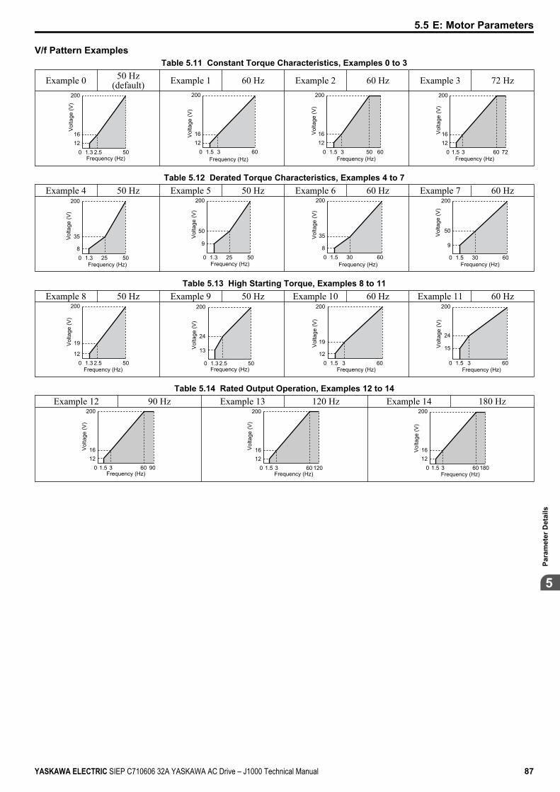
V/f Pattern ExamplesTable 5.11 Constant Torque Characteristics, Examples 0 to 3
Example 0 50 Hz(default) Example 1 60 Hz Example 2 60 Hz Example 3 72 Hz
012
200
1.3 2.5 50
16
Vol
tage
(V)
Frequency (Hz)0
1216
200
1.5 3 60
Vol
tage
(V)
Frequency (Hz)0
1216
200
1.5 3 6050
Vol
tage
(V)
Frequency (Hz)0
1216
200
1.5 3 7260
Vol
tage
(V)
Frequency (Hz)
Table 5.12 Derated Torque Characteristics, Examples 4 to 7Example 4 50 Hz Example 5 50 Hz Example 6 60 Hz Example 7 60 Hz
08
200
1.3 25 50
35Volta
ge (V
)
Frequency (Hz)0
9
200
1.3 25 50
50
Vol
tage
(V)
Frequency (Hz)08
200
1.5 30 60
35Vol
tage
(V)
Frequency (Hz)0
9
200
1.5 30 60
50
Vol
tage
(V)
Frequency (Hz)
Table 5.13 High Starting Torque, Examples 8 to 11Example 8 50 Hz Example 9 50 Hz Example 10 60 Hz Example 11 60 Hz
012
200
1.3 2.5 50
19Vol
tage
(V)
Frequency (Hz)0
13
200
1.3 2.5 50
24
Vol
tage
(V)
Frequency (Hz)0
12
200
1.5 3 60
19Vol
tage
(V)
Frequency (Hz)0
15
200
1.5 3 60
24
Vol
tage
(V)
Frequency (Hz)
Table 5.14 Rated Output Operation, Examples 12 to 14Example 12 90 Hz Example 13 120 Hz Example 14 180 Hz
01216
200
1.5 3 9060
Vol
tage
(V)
Frequency (Hz)0
1216
200
1.5 3 12060
Vol
tage
(V)
Frequency (Hz)0
1216
200
1.5 3 18060
Vol
tage
(V)
Frequency (Hz)
5.5 E: Motor Parameters
YASKAWA ELECTRIC SIEP C710606 32A YASKAWA AC Drive – J1000 Technical Manual 87
5
Para
met
er D
etai
ls
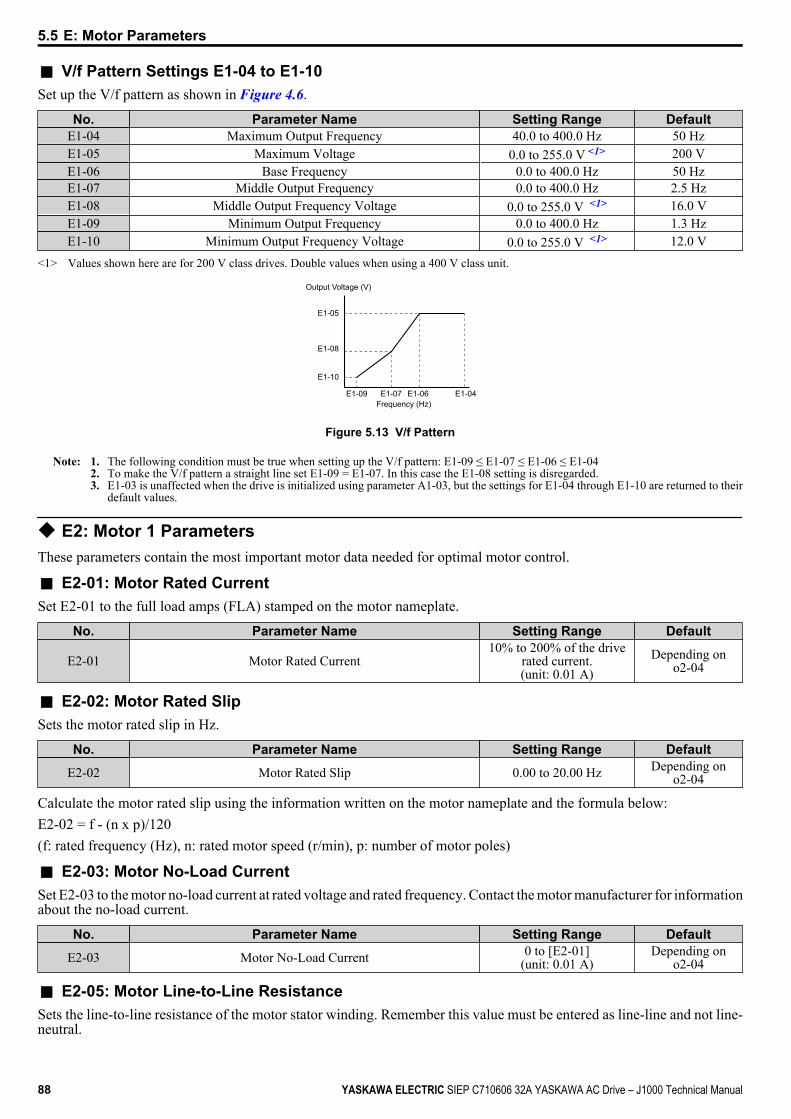
n V/f Pattern Settings E1-04 to E1-10Set up the V/f pattern as shown in Figure 4.6.
No. Parameter Name Setting Range DefaultE1-04 Maximum Output Frequency 40.0 to 400.0 Hz 50 HzE1-05 Maximum Voltage 0.0 to 255.0 V <1> 200 VE1-06 Base Frequency 0.0 to 400.0 Hz 50 HzE1-07 Middle Output Frequency 0.0 to 400.0 Hz 2.5 HzE1-08 Middle Output Frequency Voltage 0.0 to 255.0 V <1> 16.0 VE1-09 Minimum Output Frequency 0.0 to 400.0 Hz 1.3 HzE1-10 Minimum Output Frequency Voltage 0.0 to 255.0 V <1> 12.0 V
<1> Values shown here are for 200 V class drives. Double values when using a 400 V class unit.
E1-05
E1-08
E1-10
E1-09 E1-07 E1-06 E1-04
Output Voltage (V)
Frequency (Hz)
Figure 5.13 V/f Pattern
Note: 1. The following condition must be true when setting up the V/f pattern: E1-09 ≤ E1-07 ≤ E1-06 ≤ E1-042. To make the V/f pattern a straight line set E1-09 = E1-07. In this case the E1-08 setting is disregarded.3. E1-03 is unaffected when the drive is initialized using parameter A1-03, but the settings for E1-04 through E1-10 are returned to their
default values.
u E2: Motor 1 ParametersThese parameters contain the most important motor data needed for optimal motor control.
n E2-01: Motor Rated CurrentSet E2-01 to the full load amps (FLA) stamped on the motor nameplate.
No. Parameter Name Setting Range Default
E2-01 Motor Rated Current10% to 200% of the drive
rated current.(unit: 0.01 A)
Depending ono2-04
n E2-02: Motor Rated SlipSets the motor rated slip in Hz.
No. Parameter Name Setting Range Default
E2-02 Motor Rated Slip 0.00 to 20.00 Hz Depending ono2-04
Calculate the motor rated slip using the information written on the motor nameplate and the formula below:E2-02 = f - (n x p)/120(f: rated frequency (Hz), n: rated motor speed (r/min), p: number of motor poles)
n E2-03: Motor No-Load CurrentSet E2-03 to the motor no-load current at rated voltage and rated frequency. Contact the motor manufacturer for informationabout the no-load current.
No. Parameter Name Setting Range Default
E2-03 Motor No-Load Current 0 to [E2-01](unit: 0.01 A)
Depending ono2-04
n E2-05: Motor Line-to-Line ResistanceSets the line-to-line resistance of the motor stator winding. Remember this value must be entered as line-line and not line-neutral.
5.5 E: Motor Parameters
88 YASKAWA ELECTRIC SIEP C710606 32A YASKAWA AC Drive – J1000 Technical Manual
No. Parameter Name Setting Range Default
E2-05 Motor Line-to-Line Resistance 0.000 to 65.000 Ω Depending ono2-04
Note: The setting range becomes 0.00 to 130.00 when using JoBA0002, Jo2A0002, Jo4A0001 and smaller.
Contact the motor manufacturer to find out the line-to-line resistance or measure it manually. When using the manufacturerMotor Test Report, calculate E2-05 by the formulas below.• E-type insulation: Multiply 0.92 times the resistance value (Ω) listed on the Test Report at 75 °C• B-type insulation: Multiply 0.92 times the resistance value (Ω) listed on the Test Report at 75 °C.• F-type insulation: Multiply 0.87 times the resistance value (Ω) listed on the Test Report at 115 °C.
5.5 E: Motor Parameters
YASKAWA ELECTRIC SIEP C710606 32A YASKAWA AC Drive – J1000 Technical Manual 89
5
Para
met
er D
etai
ls
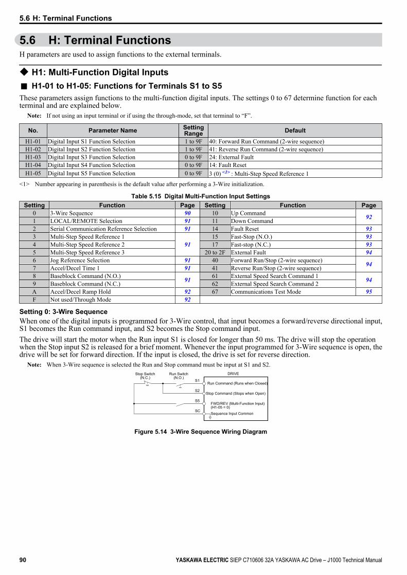
5.6 H: Terminal FunctionsH parameters are used to assign functions to the external terminals.
u H1: Multi-Function Digital Inputsn H1-01 to H1-05: Functions for Terminals S1 to S5These parameters assign functions to the multi-function digital inputs. The settings 0 to 67 determine function for eachterminal and are explained below.
Note: If not using an input terminal or if using the through-mode, set that terminal to “F”.
No. Parameter Name SettingRange Default
H1-01 Digital Input S1 Function Selection 1 to 9F 40: Forward Run Command (2-wire sequence)H1-02 Digital Input S2 Function Selection 1 to 9F 41: Reverse Run Command (2-wire sequence)H1-03 Digital Input S3 Function Selection 0 to 9F 24: External FaultH1-04 Digital Input S4 Function Selection 0 to 9F 14: Fault ResetH1-05 Digital Input S5 Function Selection 0 to 9F 3 (0) <1> : Multi-Step Speed Reference 1
<1> Number appearing in parenthesis is the default value after performing a 3-Wire initialization.
Table 5.15 Digital Multi-Function Input SettingsSetting Function Page Setting Function Page
0 3-Wire Sequence 90 10 Up Command 921 LOCAL/REMOTE Selection 91 11 Down Command2 Serial Communication Reference Selection 91 14 Fault Reset 933 Multi-Step Speed Reference 1
9115 Fast-Stop (N.O.) 93
4 Multi-Step Speed Reference 2 17 Fast-stop (N.C.) 935 Multi-Step Speed Reference 3 20 to 2F External Fault 946 Jog Reference Selection 91 40 Forward Run/Stop (2-wire sequence) 947 Accel/Decel Time 1 91 41 Reverse Run/Stop (2-wire sequence)8 Baseblock Command (N.O.) 91 61 External Speed Search Command 1 949 Baseblock Command (N.C.) 62 External Speed Search Command 2A Accel/Decel Ramp Hold 92 67 Communications Test Mode 95F Not used/Through Mode 92
Setting 0: 3-Wire SequenceWhen one of the digital inputs is programmed for 3-Wire control, that input becomes a forward/reverse directional input,S1 becomes the Run command input, and S2 becomes the Stop command input.The drive will start the motor when the Run input S1 is closed for longer than 50 ms. The drive will stop the operationwhen the Stop input S2 is released for a brief moment. Whenever the input programmed for 3-Wire sequence is open, thedrive will be set for forward direction. If the input is closed, the drive is set for reverse direction.
Note: When 3-Wire sequence is selected the Run and Stop command must be input at S1 and S2.
S1
S2
S5
SC
Run Command (Runs when Closed)
DRIVEStop Switch(N.C.)
Run Switch(N.O.)
Stop Command (Stops when Open)
FWD/REV (Multi-Function Input)(H1-05 = 0)
Sequence Input Common
Figure 5.14 3-Wire Sequence Wiring Diagram
5.6 H: Terminal Functions
90 YASKAWA ELECTRIC SIEP C710606 32A YASKAWA AC Drive – J1000 Technical Manual
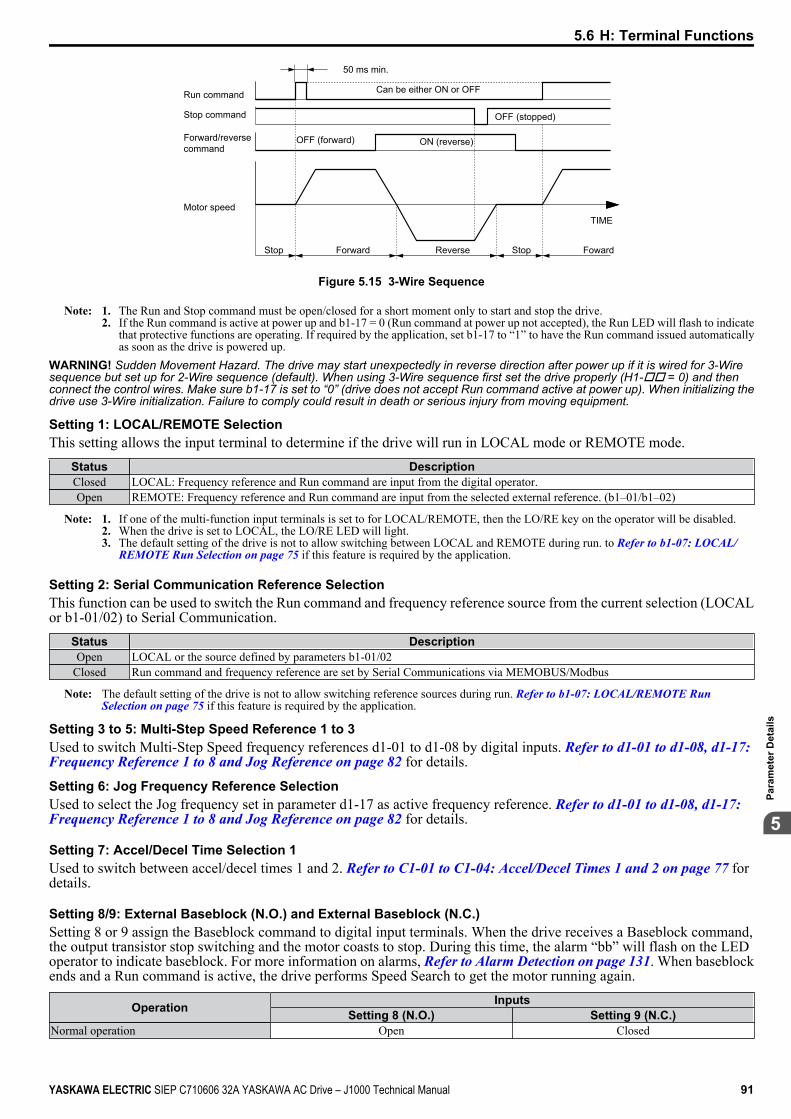
50 ms min.
Run command
OFF (stopped)
Can be either ON or OFF
OFF (forward)
Motor speed
Forward/reversecommand
Stop command
Stop Reverse Stop Foward
TIME
Forward
ON (reverse)
Figure 5.15 3-Wire Sequence
Note: 1. The Run and Stop command must be open/closed for a short moment only to start and stop the drive.2. If the Run command is active at power up and b1-17 = 0 (Run command at power up not accepted), the Run LED will flash to indicate
that protective functions are operating. If required by the application, set b1-17 to “1” to have the Run command issued automaticallyas soon as the drive is powered up.
WARNING! Sudden Movement Hazard. The drive may start unexpectedly in reverse direction after power up if it is wired for 3-Wiresequence but set up for 2-Wire sequence (default). When using 3-Wire sequence first set the drive properly (H1-oo = 0) and thenconnect the control wires. Make sure b1-17 is set to “0” (drive does not accept Run command active at power up). When initializing thedrive use 3-Wire initialization. Failure to comply could result in death or serious injury from moving equipment.
Setting 1: LOCAL/REMOTE SelectionThis setting allows the input terminal to determine if the drive will run in LOCAL mode or REMOTE mode.
Status DescriptionClosed LOCAL: Frequency reference and Run command are input from the digital operator.Open REMOTE: Frequency reference and Run command are input from the selected external reference. (b1–01/b1–02)
Note: 1. If one of the multi-function input terminals is set to for LOCAL/REMOTE, then the LO/RE key on the operator will be disabled.2. When the drive is set to LOCAL, the LO/RE LED will light.3. The default setting of the drive is not to allow switching between LOCAL and REMOTE during run. to Refer to b1-07: LOCAL/
REMOTE Run Selection on page 75 if this feature is required by the application.
Setting 2: Serial Communication Reference SelectionThis function can be used to switch the Run command and frequency reference source from the current selection (LOCALor b1-01/02) to Serial Communication.
Status DescriptionOpen LOCAL or the source defined by parameters b1-01/02
Closed Run command and frequency reference are set by Serial Communications via MEMOBUS/Modbus
Note: The default setting of the drive is not to allow switching reference sources during run. Refer to b1-07: LOCAL/REMOTE Run Selection on page 75 if this feature is required by the application.
Setting 3 to 5: Multi-Step Speed Reference 1 to 3Used to switch Multi-Step Speed frequency references d1-01 to d1-08 by digital inputs. Refer to d1-01 to d1-08, d1-17: Frequency Reference 1 to 8 and Jog Reference on page 82 for details.
Setting 6: Jog Frequency Reference SelectionUsed to select the Jog frequency set in parameter d1-17 as active frequency reference. Refer to d1-01 to d1-08, d1-17: Frequency Reference 1 to 8 and Jog Reference on page 82 for details.
Setting 7: Accel/Decel Time Selection 1Used to switch between accel/decel times 1 and 2. Refer to C1-01 to C1-04: Accel/Decel Times 1 and 2 on page 77 fordetails.
Setting 8/9: External Baseblock (N.O.) and External Baseblock (N.C.)Setting 8 or 9 assign the Baseblock command to digital input terminals. When the drive receives a Baseblock command,the output transistor stop switching and the motor coasts to stop. During this time, the alarm “bb” will flash on the LEDoperator to indicate baseblock. For more information on alarms, Refer to Alarm Detection on page 131. When baseblockends and a Run command is active, the drive performs Speed Search to get the motor running again.
Operation InputsSetting 8 (N.O.) Setting 9 (N.C.)
Normal operation Open Closed
5.6 H: Terminal Functions
YASKAWA ELECTRIC SIEP C710606 32A YASKAWA AC Drive – J1000 Technical Manual 91
5
Para
met
er D
etai
ls
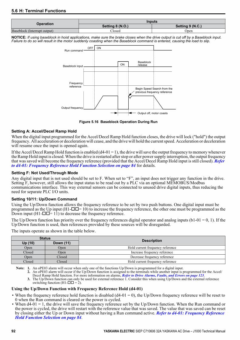
Operation InputsSetting 8 (N.O.) Setting 9 (N.C.)
Baseblock (Interrupt output) Closed Open
NOTICE: If using baseblock in hoist applications, make sure the brake closes when the drive output is cut off by a Baseblock input.Failure to do so will result in the motor suddenly coasting when the Baseblock command is entered, causing the load to slip.
Begin Speed Search from the previous frequency reference
Run command
Baseblock input
Frequency reference
Output frequency
OFF ON
Output off, motor coasts
ONBaseblock release
Figure 5.16 Baseblock Operation During Run
Setting A: Accel/Decel Ramp HoldWhen the digital input programmed for the Accel/Decel Ramp Hold function closes, the drive will lock ("hold") the outputfrequency. All acceleration or deceleration will cease, and the drive will hold the current speed. Acceleration or decelerationwill resume once the input is opened again.If the Accel/Decel Ramp Hold function is enabled (d4-01 = 1), the drive will save the output frequency to memory wheneverthe Ramp Hold input is closed. When the drive is restarted after stop or after power supply interruption, the output frequencythat was saved will become the frequency reference (provided that the Accel/Decel Ramp Hold input is still closed). Refer to d4-01: Frequency Reference Hold Function Selection on page 84 for details.
Setting F: Not Used/Through ModeAny digital input that is not used should be set to F. When set to “F”, an input does not trigger any function in the drive.Setting F, however, still allows the input status to be read out by a PLC via an optional MEMOBUS/Modbuscommunications interface. This way external sensors can be connected to unused drive digital inputs, thus reducing theneed for separate PLC I/O units.
Setting 10/11: Up/Down CommandUsing the Up/Down function allows the frequency reference to be set by two push buttons. One digital input must beprogrammed as the Up input (H1-oo= 10) to increase the frequency reference, the other one must be programmed as theDown input (H1-oo= 11) to decrease the frequency reference.The Up/Down function has priority over the frequency references digital operator and analog inputs (b1-01 = 0, 1). If theUp/Down function is used, then references provided by these sources will be disregarded.The inputs operate as shown in the table below.
Status DescriptionUp (10) Down (11)Open Open Hold current frequency reference
Closed Open Increase frequency referenceOpen Closed Decrease frequency reference
Closed Closed Hold current frequency reference
Note: 1. An oPE03 alarm will occur when only one of the functions Up/Down is programmed for a digital input.2. An oPE03 alarm will occur if the Up/Down function is assigned to the terminals while another input is programmed for the Accel/
Decel Ramp Hold function. For more information on alarms, Refer to Drive Alarms, Faults, and Errors on page 123.3. The Up/Down function can only be used for external reference 1. Consider this when using Up/Down and the external reference
switching function (H1-oo = 2).
Using the Up/Down Function with Frequency Reference Hold (d4-01)• When the frequency reference hold function is disabled (d4-01 = 0), the Up/Down frequency reference will be reset to
0 when the Run command is cleared or the power is cycled.• When d4-01 = 1, the drive will save the frequency reference set by the Up/Down function. When the Run command or
the power is cycled, the drive will restart with the reference value that was saved. The value that was saved can be resetby closing either the Up or Down input without having a Run command active. Refer to d4-01: Frequency Reference Hold Function Selection on page 84.
5.6 H: Terminal Functions
92 YASKAWA ELECTRIC SIEP C710606 32A YASKAWA AC Drive – J1000 Technical Manual
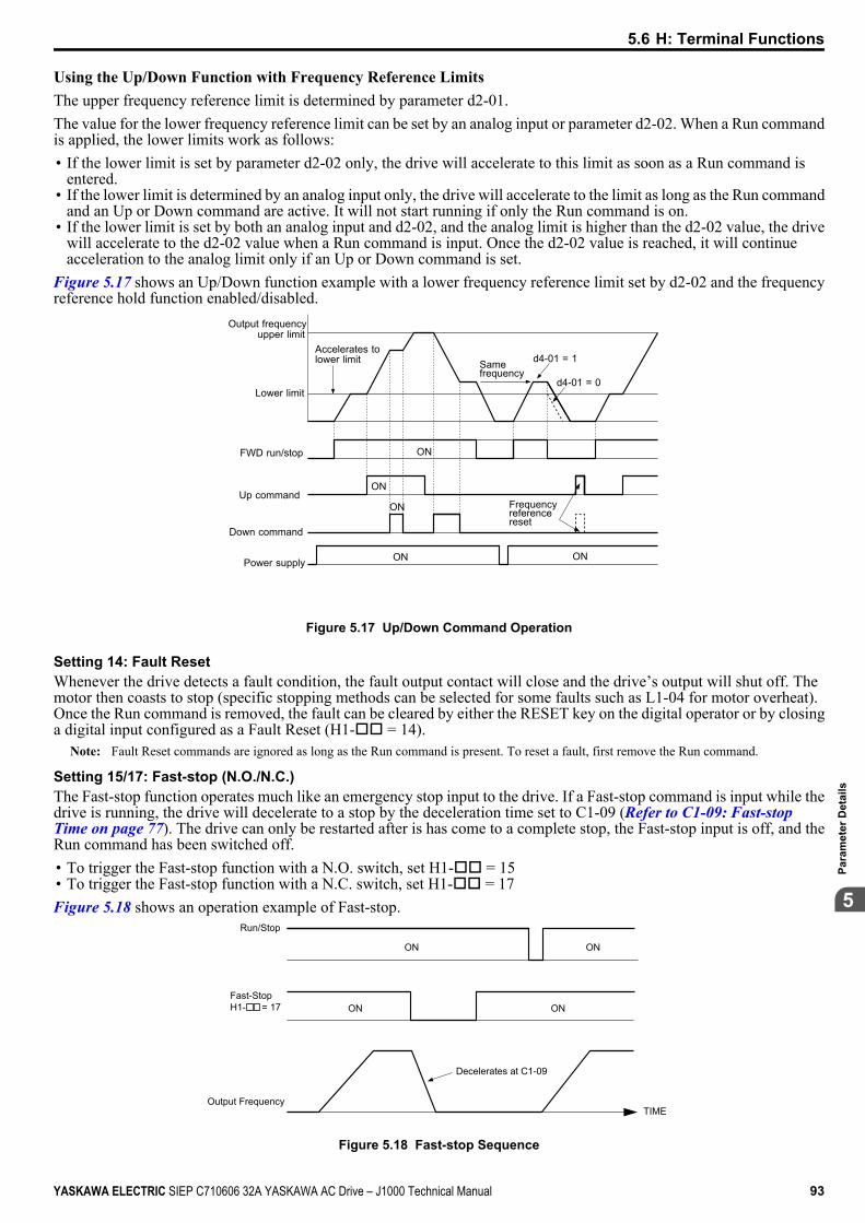
Using the Up/Down Function with Frequency Reference LimitsThe upper frequency reference limit is determined by parameter d2-01.The value for the lower frequency reference limit can be set by an analog input or parameter d2-02. When a Run commandis applied, the lower limits work as follows:• If the lower limit is set by parameter d2-02 only, the drive will accelerate to this limit as soon as a Run command is
entered.• If the lower limit is determined by an analog input only, the drive will accelerate to the limit as long as the Run command
and an Up or Down command are active. It will not start running if only the Run command is on.• If the lower limit is set by both an analog input and d2-02, and the analog limit is higher than the d2-02 value, the drive
will accelerate to the d2-02 value when a Run command is input. Once the d2-02 value is reached, it will continueacceleration to the analog limit only if an Up or Down command is set.
Figure 5.17 shows an Up/Down function example with a lower frequency reference limit set by d2-02 and the frequencyreference hold function enabled/disabled.
Accelerates tolower limit
Output frequencyupper limit
Lower limit
FWD run/stop
Up command
Down command
Power supply
Same frequency
d4-01 = 1
d4-01 = 0
ONON
ON
ON
ON
Frequency referencereset
Figure 5.17 Up/Down Command Operation
Setting 14: Fault ResetWhenever the drive detects a fault condition, the fault output contact will close and the drive’s output will shut off. Themotor then coasts to stop (specific stopping methods can be selected for some faults such as L1-04 for motor overheat).Once the Run command is removed, the fault can be cleared by either the RESET key on the digital operator or by closinga digital input configured as a Fault Reset (H1-oo = 14).
Note: Fault Reset commands are ignored as long as the Run command is present. To reset a fault, first remove the Run command.
Setting 15/17: Fast-stop (N.O./N.C.)The Fast-stop function operates much like an emergency stop input to the drive. If a Fast-stop command is input while thedrive is running, the drive will decelerate to a stop by the deceleration time set to C1-09 (Refer to C1-09: Fast-stop Time on page 77). The drive can only be restarted after is has come to a complete stop, the Fast-stop input is off, and theRun command has been switched off.• To trigger the Fast-stop function with a N.O. switch, set H1-oo = 15• To trigger the Fast-stop function with a N.C. switch, set H1-oo = 17Figure 5.18 shows an operation example of Fast-stop.
Run/Stop
TIME
Fast-Stop H1- = 17
Decelerates at C1-09
ON ON
ONON
Output Frequency
Figure 5.18 Fast-stop Sequence
5.6 H: Terminal Functions
YASKAWA ELECTRIC SIEP C710606 32A YASKAWA AC Drive – J1000 Technical Manual 93
5
Para
met
er D
etai
ls

NOTICE: Rapid deceleration can trigger an overvoltage fault. When faulted, the drive output shuts off, and the motor coasts. To avoidthis uncontrolled motor state and to ensure that the motor stops quickly and safely, set an appropriate Fast-stop time to C1-09.
Setting 20 to 2F: External FaultBy using the External Fault function, the drive can be stopped when problems occur with external devices.To use the external fault function, set one of the multi-function digital inputs to any value between 20 to 2F. The operatorwill display EFo where o is the number of the terminal (terminal So) to which the external fault signal is assigned.For example, if an external fault signal is input to terminal S3, “EF3” will be displayed.Select the value to be set in H1-oo from a combination of any of the following three conditions:• Signal input level from peripheral devices (N.O./N.C.)• External fault detection method• Operation after external fault detectionThe following table shows the relationship between the conditions and the value set to H1-oo:
SettingTerminal Status <1> Detection Method <2> Stopping Method
N.O. N.C. AlwaysDetected
Detectedduring Run
onlyRamp to Stop
(fault)Coast to Stop
(fault)Fast-stop
(fault)Alarm Only(continuerunning)
20 O O O 21 O O O 22 O O O 23 O O O 24 O O O 25 O O O 26 O O O 27 O O O 28 O O O 29 O O O 2A O O O 2B O O O 2C O O O2D O O O2E O O O2F O O O
<1> Determine the terminal status for each fault, i.e., whether the terminal is normally open or normally closed.<2> Determine whether detection for each fault should be enabled only during run or always detected.
Setting 40/41: Forward Run/Reverse Run Command for 2-Wire SequenceSets the drive for 2-Wire sequence.When the input set to 40 is closed, the drive operates in the forward direction. When the input set for 41 is closed, the drivewill operate in reverse. Closing both inputs at the same time will result in an external fault.
Note: These functions are assigned to the terminals S1 and S2 when the drive is initialized for 2-Wire sequence.
S1
S2
SC
DriveForward Run
Reverse Run
Digital Input Common
Figure 5.19 Example Wiring Diagram for 2-Wire Sequence
Setting 61/62: Speed Search 1/2These input functions can be used to enable Speed Search. When the Speed Search 1 input (H1-oo = 61) is enabled thedrive will search the motor speed starting from the maximum output frequency. With Speed Search 2 input (H1-oo =62) enabled the Speed Search will be performed starting from the frequency reference.
Note: Operator error oPE03 will result if both Speed Search 1 and Speed Search 2 are set to the input terminals at the same time.
5.6 H: Terminal Functions
94 YASKAWA ELECTRIC SIEP C710606 32A YASKAWA AC Drive – J1000 Technical Manual
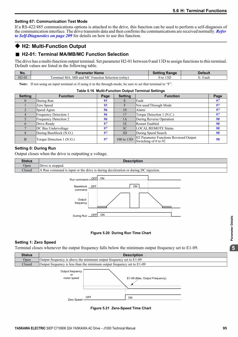
Setting 67: Communication Test ModeIf a RS-422/485 communications options is attached to the drive, this function can be used to perform a self-diagnosis ofthe communication interface. The drive transmits data and then confirms the communications are received normally. Refer to Self-Diagnostics on page 209 for details on how to use this function.
u H2: Multi-Function Outputn H2-01: Terminal MA/MB/MC Function SelectionThe drive has a multi-function output terminal. Set parameter H2-01 between 0 and 13D to assign functions to this terminal.Default values are listed in the following table.
No. Parameter Name Setting Range DefaultH2-01 Terminal MA, MB and MC Function Selection (relay) 0 to 13D E: Fault
Note: If not using an input terminal or if using it in the through-mode, be sure to set that terminal to “F”.
Table 5.16 Multi-Function Output Terminal SettingsSetting Function Page Setting Function Page
0 During Run 95 E Fault 971 Zero Speed 95 F Not used/Through Mode 972 Speed Agree 96 10 Alarm 974 Frequency Detection 1 96 17 Torque Detection 1 (N.C.) 975 Frequency Detection 2 96 1A During Reverse Operation 986 Drive Ready 97 1E Restart Enabled 987 DC Bus Undervoltage 97 3C LOCAL/REMOTE Status 988 During Baseblock (N.O.) 97 3D During Speed Search 98
B Torque Detection 1 (N.O.) 97 100 to 13D H2 Parameter Functions Reversed OutputSwitching of 0 to 92 98
Setting 0: During RunOutput closes when the drive is outputting a voltage.
Status DescriptionOpen Drive is stopped.
Closed A Run command is input or the drive is during deceleration or during DC injection.
ON
ON
OFF
OFF
ONOFF
Run command
Baseblock command
Output frequency
During Run
Figure 5.20 During Run Time Chart
Setting 1: Zero SpeedTerminal closes whenever the output frequency falls below the minimum output frequency set to E1-09.
Status DescriptionOpen Output frequency is above the minimum output frequency set to E1-09
Closed Output frequency is less than the minimum output frequency set to E1-09
OFF
Output frequency or
motor speed
Zero SpeedON
E1-09 (Max. Output Frequency)
Figure 5.21 Zero-Speed Time Chart
5.6 H: Terminal Functions
YASKAWA ELECTRIC SIEP C710606 32A YASKAWA AC Drive – J1000 Technical Manual 95
5
Para
met
er D
etai
ls
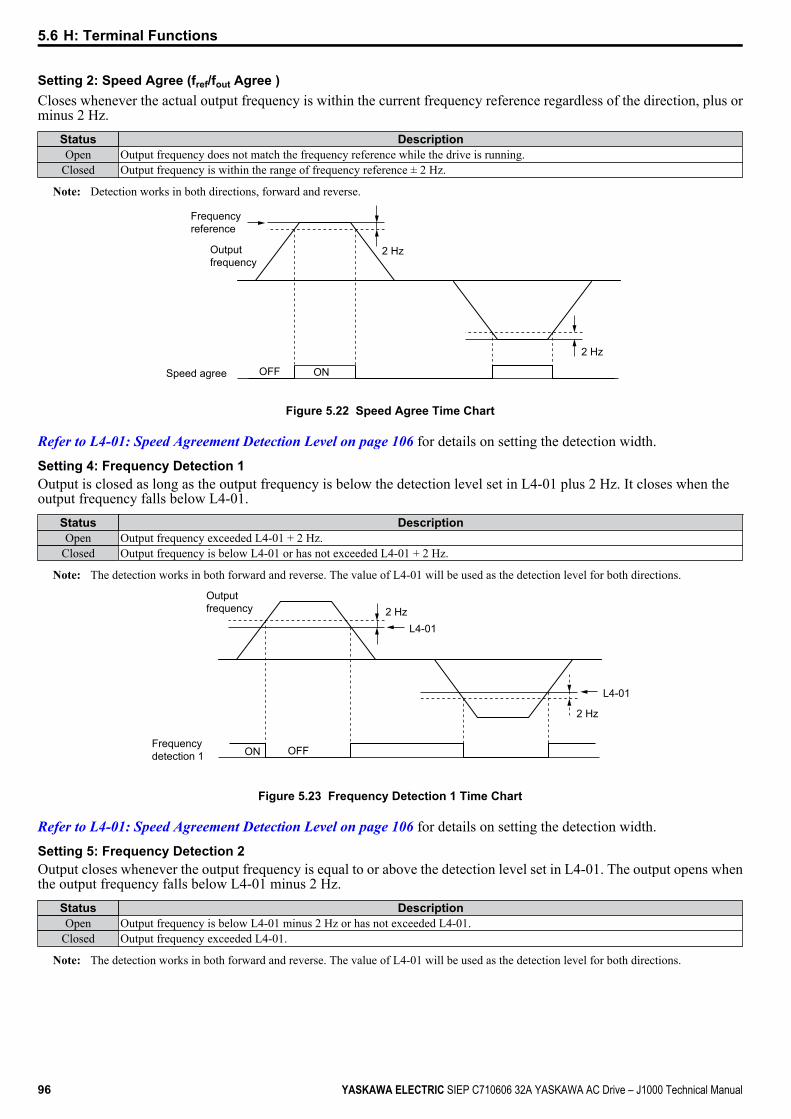
Setting 2: Speed Agree (fref/fout Agree )Closes whenever the actual output frequency is within the current frequency reference regardless of the direction, plus orminus 2 Hz.
Status DescriptionOpen Output frequency does not match the frequency reference while the drive is running.
Closed Output frequency is within the range of frequency reference ± 2 Hz.
Note: Detection works in both directions, forward and reverse.
2 Hz
2 Hz
Frequency reference
Output frequency
Speed agree ONOFF
Figure 5.22 Speed Agree Time Chart
Refer to L4-01: Speed Agreement Detection Level on page 106 for details on setting the detection width.
Setting 4: Frequency Detection 1Output is closed as long as the output frequency is below the detection level set in L4-01 plus 2 Hz. It closes when theoutput frequency falls below L4-01.
Status DescriptionOpen Output frequency exceeded L4-01 + 2 Hz.
Closed Output frequency is below L4-01 or has not exceeded L4-01 + 2 Hz.
Note: The detection works in both forward and reverse. The value of L4-01 will be used as the detection level for both directions.
Output frequency 2 Hz
Frequency detection 1 ON OFF
2 Hz
L4-01
L4-01
Figure 5.23 Frequency Detection 1 Time Chart
Refer to L4-01: Speed Agreement Detection Level on page 106 for details on setting the detection width.
Setting 5: Frequency Detection 2Output closes whenever the output frequency is equal to or above the detection level set in L4-01. The output opens whenthe output frequency falls below L4-01 minus 2 Hz.
Status DescriptionOpen Output frequency is below L4-01 minus 2 Hz or has not exceeded L4-01.
Closed Output frequency exceeded L4-01.
Note: The detection works in both forward and reverse. The value of L4-01 will be used as the detection level for both directions.
5.6 H: Terminal Functions
96 YASKAWA ELECTRIC SIEP C710606 32A YASKAWA AC Drive – J1000 Technical Manual
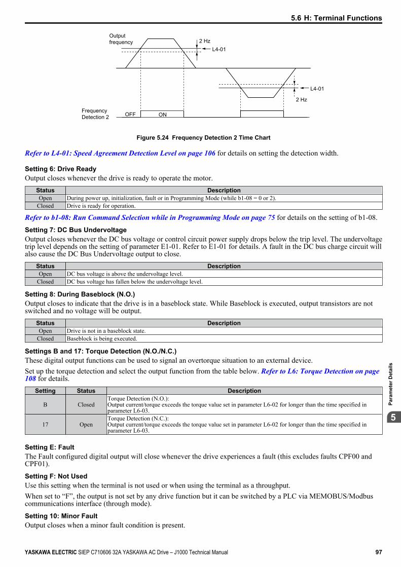
Output frequency 2 Hz
Frequency Detection 2 ONOFF
2 Hz
L4-01
L4-01
Figure 5.24 Frequency Detection 2 Time Chart
Refer to L4-01: Speed Agreement Detection Level on page 106 for details on setting the detection width.
Setting 6: Drive ReadyOutput closes whenever the drive is ready to operate the motor.
Status DescriptionOpen During power up, initialization, fault or in Programming Mode (while b1-08 = 0 or 2).
Closed Drive is ready for operation.
Refer to b1-08: Run Command Selection while in Programming Mode on page 75 for details on the setting of b1-08.
Setting 7: DC Bus UndervoltageOutput closes whenever the DC bus voltage or control circuit power supply drops below the trip level. The undervoltagetrip level depends on the setting of parameter E1-01. Refer to E1-01 for details. A fault in the DC bus charge circuit willalso cause the DC Bus Undervoltage output to close.
Status DescriptionOpen DC bus voltage is above the undervoltage level.
Closed DC bus voltage has fallen below the undervoltage level.
Setting 8: During Baseblock (N.O.)Output closes to indicate that the drive is in a baseblock state. While Baseblock is executed, output transistors are notswitched and no voltage will be output.
Status DescriptionOpen Drive is not in a baseblock state.
Closed Baseblock is being executed.
Settings B and 17: Torque Detection (N.O./N.C.)These digital output functions can be used to signal an overtorque situation to an external device.Set up the torque detection and select the output function from the table below. Refer to L6: Torque Detection on page 108 for details.
Setting Status Description
B ClosedTorque Detection (N.O.):Output current/torque exceeds the torque value set in parameter L6-02 for longer than the time specified inparameter L6-03.
17 OpenTorque Detection (N.C.):Output current/torque exceeds the torque value set in parameter L6-02 for longer than the time specified inparameter L6-03.
Setting E: FaultThe Fault configured digital output will close whenever the drive experiences a fault (this excludes faults CPF00 andCPF01).
Setting F: Not UsedUse this setting when the terminal is not used or when using the terminal as a throughput.When set to “F”, the output is not set by any drive function but it can be switched by a PLC via MEMOBUS/Modbuscommunications interface (through mode).
Setting 10: Minor FaultOutput closes when a minor fault condition is present.
5.6 H: Terminal Functions
YASKAWA ELECTRIC SIEP C710606 32A YASKAWA AC Drive – J1000 Technical Manual 97
5
Para
met
er D
etai
ls
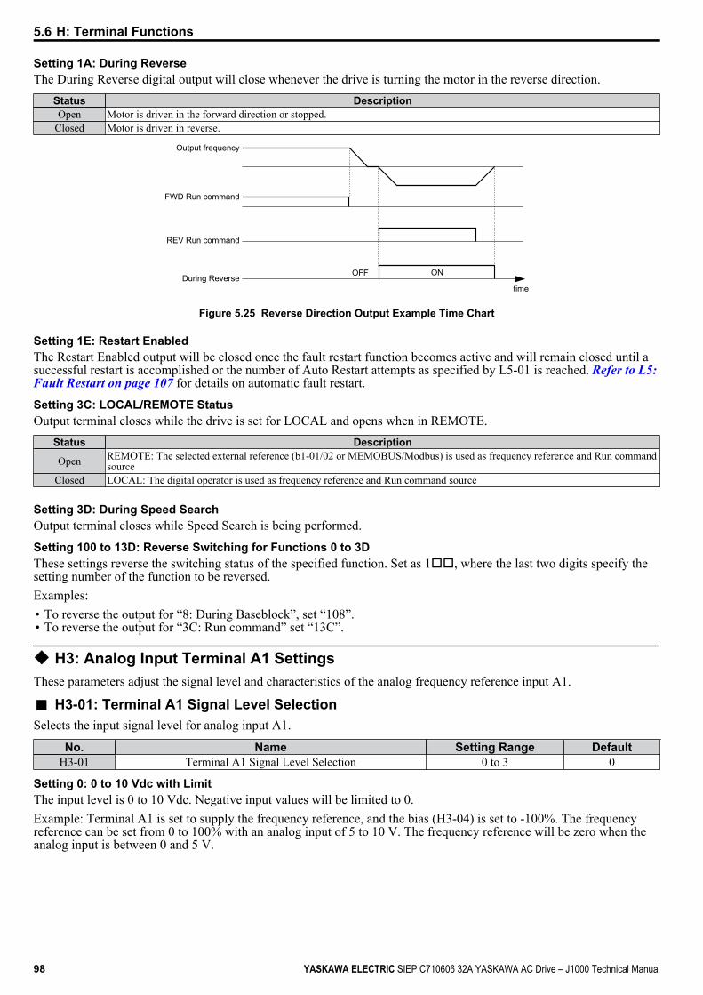
Setting 1A: During ReverseThe During Reverse digital output will close whenever the drive is turning the motor in the reverse direction.
Status DescriptionOpen Motor is driven in the forward direction or stopped.
Closed Motor is driven in reverse.
Output frequency
time
FWD Run command
REV Run command
During ReverseOFF ON
Figure 5.25 Reverse Direction Output Example Time Chart
Setting 1E: Restart EnabledThe Restart Enabled output will be closed once the fault restart function becomes active and will remain closed until asuccessful restart is accomplished or the number of Auto Restart attempts as specified by L5-01 is reached. Refer to L5: Fault Restart on page 107 for details on automatic fault restart.
Setting 3C: LOCAL/REMOTE StatusOutput terminal closes while the drive is set for LOCAL and opens when in REMOTE.
Status Description
Open REMOTE: The selected external reference (b1-01/02 or MEMOBUS/Modbus) is used as frequency reference and Run commandsource
Closed LOCAL: The digital operator is used as frequency reference and Run command source
Setting 3D: During Speed SearchOutput terminal closes while Speed Search is being performed.
Setting 100 to 13D: Reverse Switching for Functions 0 to 3DThese settings reverse the switching status of the specified function. Set as 1oo, where the last two digits specify thesetting number of the function to be reversed.Examples:• To reverse the output for “8: During Baseblock”, set “108”.• To reverse the output for “3C: Run command” set “13C”.
u H3: Analog Input Terminal A1 SettingsThese parameters adjust the signal level and characteristics of the analog frequency reference input A1.
n H3-01: Terminal A1 Signal Level SelectionSelects the input signal level for analog input A1.
No. Name Setting Range DefaultH3-01 Terminal A1 Signal Level Selection 0 to 3 0
Setting 0: 0 to 10 Vdc with LimitThe input level is 0 to 10 Vdc. Negative input values will be limited to 0.Example: Terminal A1 is set to supply the frequency reference, and the bias (H3-04) is set to -100%. The frequencyreference can be set from 0 to 100% with an analog input of 5 to 10 V. The frequency reference will be zero when theanalog input is between 0 and 5 V.
5.6 H: Terminal Functions
98 YASKAWA ELECTRIC SIEP C710606 32A YASKAWA AC Drive – J1000 Technical Manual
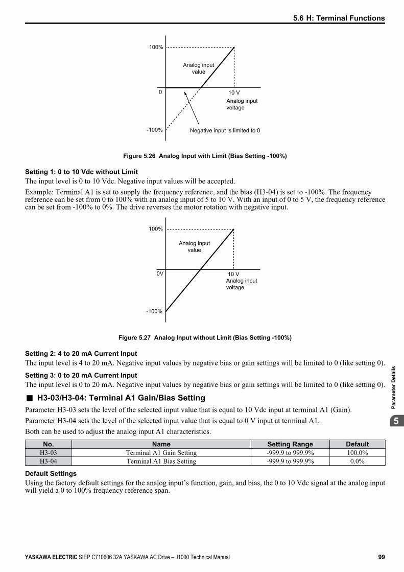
0 10 V
100%
-100%
Analog input voltage
Analog input value
Negative input is limited to 0
Figure 5.26 Analog Input with Limit (Bias Setting -100%)
Setting 1: 0 to 10 Vdc without LimitThe input level is 0 to 10 Vdc. Negative input values will be accepted.Example: Terminal A1 is set to supply the frequency reference, and the bias (H3-04) is set to -100%. The frequencyreference can be set from 0 to 100% with an analog input of 5 to 10 V. With an input of 0 to 5 V, the frequency referencecan be set from -100% to 0%. The drive reverses the motor rotation with negative input.
0V 10 V
100%
-100%
Analog input voltage
Analog input value
Figure 5.27 Analog Input without Limit (Bias Setting -100%)
Setting 2: 4 to 20 mA Current InputThe input level is 4 to 20 mA. Negative input values by negative bias or gain settings will be limited to 0 (like setting 0).
Setting 3: 0 to 20 mA Current InputThe input level is 0 to 20 mA. Negative input values by negative bias or gain settings will be limited to 0 (like setting 0).
n H3-03/H3-04: Terminal A1 Gain/Bias SettingParameter H3-03 sets the level of the selected input value that is equal to 10 Vdc input at terminal A1 (Gain).Parameter H3-04 sets the level of the selected input value that is equal to 0 V input at terminal A1.Both can be used to adjust the analog input A1 characteristics.
No. Name Setting Range DefaultH3-03 Terminal A1 Gain Setting -999.9 to 999.9% 100.0%H3-04 Terminal A1 Bias Setting -999.9 to 999.9% 0.0%
Default SettingsUsing the factory default settings for the analog input’s function, gain, and bias, the 0 to 10 Vdc signal at the analog inputwill yield a 0 to 100% frequency reference span.
5.6 H: Terminal Functions
YASKAWA ELECTRIC SIEP C710606 32A YASKAWA AC Drive – J1000 Technical Manual 99
5
Para
met
er D
etai
ls
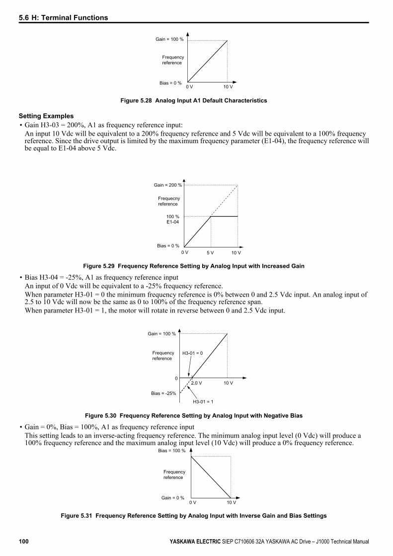
0 V 10 V
Gain = 100 %
Frequency reference
Bias = 0 %
Figure 5.28 Analog Input A1 Default Characteristics
Setting Examples• Gain H3-03 = 200%, A1 as frequency reference input:
An input 10 Vdc will be equivalent to a 200% frequency reference and 5 Vdc will be equivalent to a 100% frequencyreference. Since the drive output is limited by the maximum frequency parameter (E1-04), the frequency reference willbe equal to E1-04 above 5 Vdc.
10 V5 V0 V
Gain = 200 %
100 %
Frequecny reference
Bias = 0 %
E1-04
Figure 5.29 Frequency Reference Setting by Analog Input with Increased Gain
• Bias H3-04 = -25%, A1 as frequency reference inputAn input of 0 Vdc will be equivalent to a -25% frequency reference.When parameter H3-01 = 0 the minimum frequency reference is 0% between 0 and 2.5 Vdc input. An analog input of2.5 to 10 Vdc will now be the same as 0 to 100% of the frequency reference span.When parameter H3-01 = 1, the motor will rotate in reverse between 0 and 2.5 Vdc input.
2.0 V0
10 V
Gain = 100 %
Frequency reference
Bias = -25%
H3-01 = 0
H3-01 = 1
Figure 5.30 Frequency Reference Setting by Analog Input with Negative Bias
• Gain = 0%, Bias = 100%, A1 as frequency reference inputThis setting leads to an inverse-acting frequency reference. The minimum analog input level (0 Vdc) will produce a100% frequency reference and the maximum analog input level (10 Vdc) will produce a 0% frequency reference.
0 V 10 VGain = 0 %
Bias = 100 %
Frequency reference
Figure 5.31 Frequency Reference Setting by Analog Input with Inverse Gain and Bias Settings
5.6 H: Terminal Functions
100 YASKAWA ELECTRIC SIEP C710606 32A YASKAWA AC Drive – J1000 Technical Manual

n H3-13: Analog Input Filter Time ConstantParameter H3-13 sets the time constant for a first order filter that will be applied to analog input A1 and also to the referencevalue from potentiometer option (AI-V3/J).
No. Name Setting Range DefaultH3-13 Analog Input Filter Time Constant 0.00 to 2.00 s 0.03 s
An analog input filter can be used to prevent erratic drive control when a “noisy” analog reference is used. The driveoperation becomes more stable the longer the time programmed, but it becomes less responsive to rapidly changing analogsignals.
u H4: Multi-Function Analog Output Terminal AMThese parameters assign a function to analog output terminal AM for monitoring a specific aspect of drive performance.
n H4-01: Multi-Function Analog Terminal AM Monitor SelectionSets the desired drive monitor parameter Uo-oo to output as an analog value via terminal AM. Refer to U: Monitors on page 183 for a list of all monitors. The “Analog Output Level” columns indicates if a monitor can be applied for analogoutput.Example: Enter “103” for U1-03.
No. Name Setting Range DefaultH4-01 Multi-Function Analog Terminal AM Monitor Selection 000 to 999 102
A setting of 031 or 000 applies no drive monitor to the analog output. With this setting the terminal AM output level canbe set by a PLC via a MEMOBUS/Modbus communications interface (through mode).
n H4-02/H4-03: Multi-Function Analog Output Terminal AM Gain/BiasParameter H4-02 sets the output voltage that is equal to 100% of the monitor value. Parameter H4-03 sets the output voltageequal to 0% of the monitor value.Both values are set as a percentage of 10 V. The minimum output voltage for terminal AM is 0 V, the maximum is 10Vdc. Figure 5.32 illustrates the function of the gain and bias settings.
No. Name Setting Range DefaultH4-02 Multi-Function Analog Output Terminal AM Gain -999.9 to 999.9% 100.0%H4-03 Multi-Function Analog Output Terminal AM Bias -999.9 to 999.9% 0.0%
0 V
3 V
10 V
Bias 30% Gain 100%
Bias 0% Gain 100%
100%Monitor value0%
Gain 50% Bias 0%
Terminal AM output voltage
0 V
5 V
10 VGain 150% Bias 0%
Gain 100% Bias 0%
100%Monitor value0%
Terminal AM output voltage
Figure 5.32 Analog Output Gain/Bias Setting
When viewing the settings for H4-02, terminal AM will output a voltage that is equal to 100% of the monitor value(considering the present setting). When viewing the settings for H4-03, terminal AM will output a voltage that is equal to0% of the monitor value.
u H5: MEMOBUS/Modbus Serial CommunicationThrough the drives optional RS-422/485 interface, serial communication can be performed with programmable logiccontrollers (PLCs) or similar devices using the MEMOBUS/Modbus protocol.The H5-oo parameters are used to set up the drive for MEMOBUS/Modbus Communications. Refer to MEMOBUS/Modbus Serial Communication on page 193 for detailed descriptions of the H5-oo parameters.
5.6 H: Terminal Functions
YASKAWA ELECTRIC SIEP C710606 32A YASKAWA AC Drive – J1000 Technical Manual 101
5
Para
met
er D
etai
ls

5.7 L: Protection Functions
u L1: Motor Protection Functionsn L1-01: Motor Overload Protection Function SelectionThe drive has an electronic overload protection function that estimates the motor overload level based on output current,output frequency, thermal motor characteristics, and time. An oL1 fault will be triggered when motor overload is detected.L1-01 sets the overload protection function characteristics according to the motor being used.
No. Name Setting Range DefaultL1-01 Motor Overload Protection Selection 0 to 2 1
Setting 0: Disabled - Motor Overload Protection is not ProvidedThis setting should be used if no motor overheat protection is desired or if multiple motors are connected to one drive. Inthis case it is recommended that you install a thermal relay for each motor as show in Figure 5.33
DrivePower supply
M1MC1
MC1, MC2: Magnetic contactorsL10, L20: Thermal relays
L10
MC2 L20M2
Figure 5.33 Example of Protection Circuit Design for Multiple Motors
NOTICE: Protect each motor with individual thermal overloads when multiple motors are connected to one drive. Failure to complycould result in motor damage. Disable the electronic overload protection of the drive (L1-01 = “0: Disabled”) and protect each motorwith individual motor thermal overloads.
Setting 1: General Purpose Motor (standard self-cooled)Because the motor is self-cooled, the overload tolerance drops when the motor speed is lowered. The drive appropriatelyadjusts the electrothermal trigger point according to the motor overload characteristics, protecting the motor from overheatthroughout the entire speed range.
Overload Tolerance Overload Characteristics Cooling Ability
Motor designed to operate from linepower.
Motor cooling is most effective whenrunning at rated nameplate base
frequency (check the motorspecifications).
Continuous operation at less than linepower frequency with 100% load can
trigger motor overload protection(oL1). A fault is output and the motor
will coast to stop.
Setting 2: Drive Dedicated Motor (constant torque, 1:10)Use this setting when operating a drive duty motor with a torque ratio of 1:10. This motor type is allowed to run with 100%load from 10% up to 100% speed. Running slower speeds with full load can trigger an overload fault.
5.7 L: Protection Functions
102 YASKAWA ELECTRIC SIEP C710606 32A YASKAWA AC Drive – J1000 Technical Manual
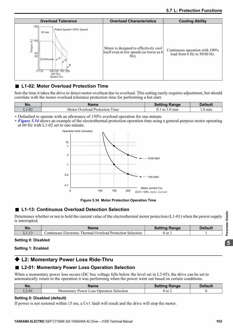
Overload Tolerance Overload Characteristics Cooling Ability
100
150
110 100120 167 200
5550
0
Rated Speed=100% Speed60 sec.
Continuous AD
B
(60 Hz)Speed (%)
Torq
ue (%
)
Motor is designed to effectively coolitself even at low speeds (as lower as 6
Hz).Continuous operation with 100%
load from 6 Hz to 50/60 Hz.
n L1-02: Motor Overload Protection TimeSets the time it takes the drive to detect motor overheat due to overload. This setting rarely requires adjustment, but shouldcorrelate with the motor overload tolerance protection time for performing a hot start.
No. Name Setting Range DefaultL1-02 Motor Overload Protection Time 0.1 to 5.0 min 1.0 min
• Defaulted to operate with an allowance of 150% overload operation for one minute.• Figure 5.34 shows an example of the electrothermal protection operation time using a general-purpose motor operating
at 60 Hz with L1-02 set to one minute.Operation time (minutes)
Cold start
Hot start
Motor current (%)E2-01 = 100% m o t o r c u r r e n t
107
3
1
0.4
0.1
0 100 150 200
Figure 5.34 Motor Protection Operation Time
n L1-13: Continuous Overload Detection SelectionDetermines whether or not to hold the current value of the electrothermal motor protection (L1-01) when the power supplyis interrupted.
No. Name Setting Range DefaultL1-13 Continuous Electronic Thermal Overload Protection Selection 0 or 1 1
Setting 0: Disabled
Setting 1: Enabled
u L2: Momentary Power Loss Ride-Thrun L2-01: Momentary Power Loss Operation SelectionWhen a momentary power loss occurs (DC bus voltage falls below the level set in L2-05), the drive can be set toautomatically return to the operation it was performing when the power went out based on certain conditions.
No. Name Setting Range DefaultL2-01 Momentary Power Loss Operation Selection 0 to 2 0
Setting 0: Disabled (default)If power is not restored within 15 ms, a Uv1 fault will result and the drive will stop the motor.
5.7 L: Protection Functions
YASKAWA ELECTRIC SIEP C710606 32A YASKAWA AC Drive – J1000 Technical Manual 103
5
Para
met
er D
etai
ls
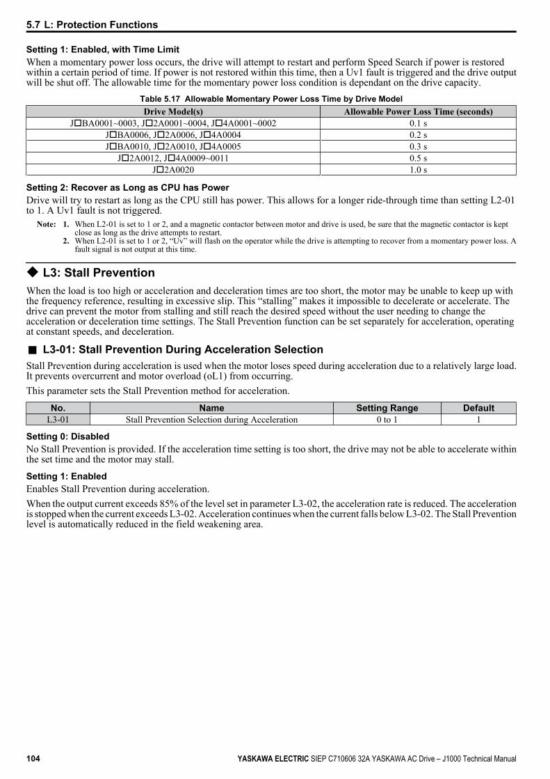
Setting 1: Enabled, with Time LimitWhen a momentary power loss occurs, the drive will attempt to restart and perform Speed Search if power is restoredwithin a certain period of time. If power is not restored within this time, then a Uv1 fault is triggered and the drive outputwill be shut off. The allowable time for the momentary power loss condition is dependant on the drive capacity.
Table 5.17 Allowable Momentary Power Loss Time by Drive ModelDrive Model(s) Allowable Power Loss Time (seconds)
JoBA0001~0003, Jo2A0001~0004, Jo4A0001~0002 0.1 sJoBA0006, Jo2A0006, Jo4A0004 0.2 sJoBA0010, Jo2A0010, Jo4A0005 0.3 s
Jo2A0012, Jo4A0009~0011 0.5 sJo2A0020 1.0 s
Setting 2: Recover as Long as CPU has PowerDrive will try to restart as long as the CPU still has power. This allows for a longer ride-through time than setting L2-01to 1. A Uv1 fault is not triggered.
Note: 1. When L2-01 is set to 1 or 2, and a magnetic contactor between motor and drive is used, be sure that the magnetic contactor is keptclose as long as the drive attempts to restart.
2. When L2-01 is set to 1 or 2, “Uv” will flash on the operator while the drive is attempting to recover from a momentary power loss. Afault signal is not output at this time.
u L3: Stall PreventionWhen the load is too high or acceleration and deceleration times are too short, the motor may be unable to keep up withthe frequency reference, resulting in excessive slip. This “stalling” makes it impossible to decelerate or accelerate. Thedrive can prevent the motor from stalling and still reach the desired speed without the user needing to change theacceleration or deceleration time settings. The Stall Prevention function can be set separately for acceleration, operatingat constant speeds, and deceleration.
n L3-01: Stall Prevention During Acceleration SelectionStall Prevention during acceleration is used when the motor loses speed during acceleration due to a relatively large load.It prevents overcurrent and motor overload (oL1) from occurring.This parameter sets the Stall Prevention method for acceleration.
No. Name Setting Range DefaultL3-01 Stall Prevention Selection during Acceleration 0 to 1 1
Setting 0: DisabledNo Stall Prevention is provided. If the acceleration time setting is too short, the drive may not be able to accelerate withinthe set time and the motor may stall.
Setting 1: EnabledEnables Stall Prevention during acceleration.When the output current exceeds 85% of the level set in parameter L3-02, the acceleration rate is reduced. The accelerationis stopped when the current exceeds L3-02. Acceleration continues when the current falls below L3-02. The Stall Preventionlevel is automatically reduced in the field weakening area.
5.7 L: Protection Functions
104 YASKAWA ELECTRIC SIEP C710606 32A YASKAWA AC Drive – J1000 Technical Manual
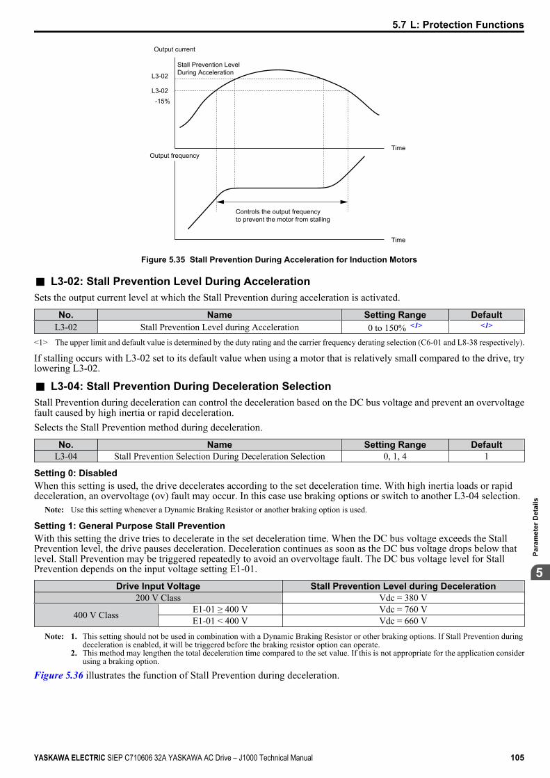
Stall Prevention Level During AccelerationL3-02
L3-02-15%
Output current
Output frequencyTime
Time
Controls the output frequency to prevent the motor from stalling
Figure 5.35 Stall Prevention During Acceleration for Induction Motors
n L3-02: Stall Prevention Level During AccelerationSets the output current level at which the Stall Prevention during acceleration is activated.
No. Name Setting Range DefaultL3-02 Stall Prevention Level during Acceleration 0 to 150% <1> <1>
<1> The upper limit and default value is determined by the duty rating and the carrier frequency derating selection (C6-01 and L8-38 respectively).
If stalling occurs with L3-02 set to its default value when using a motor that is relatively small compared to the drive, trylowering L3-02.
n L3-04: Stall Prevention During Deceleration SelectionStall Prevention during deceleration can control the deceleration based on the DC bus voltage and prevent an overvoltagefault caused by high inertia or rapid deceleration.Selects the Stall Prevention method during deceleration.
No. Name Setting Range DefaultL3-04 Stall Prevention Selection During Deceleration Selection 0, 1, 4 1
Setting 0: DisabledWhen this setting is used, the drive decelerates according to the set deceleration time. With high inertia loads or rapiddeceleration, an overvoltage (ov) fault may occur. In this case use braking options or switch to another L3-04 selection.
Note: Use this setting whenever a Dynamic Braking Resistor or another braking option is used.
Setting 1: General Purpose Stall PreventionWith this setting the drive tries to decelerate in the set deceleration time. When the DC bus voltage exceeds the StallPrevention level, the drive pauses deceleration. Deceleration continues as soon as the DC bus voltage drops below thatlevel. Stall Prevention may be triggered repeatedly to avoid an overvoltage fault. The DC bus voltage level for StallPrevention depends on the input voltage setting E1-01.
Drive Input Voltage Stall Prevention Level during Deceleration200 V Class Vdc = 380 V
400 V Class E1-01 ≥ 400 V Vdc = 760 VE1-01 < 400 V Vdc = 660 V
Note: 1. This setting should not be used in combination with a Dynamic Braking Resistor or other braking options. If Stall Prevention duringdeceleration is enabled, it will be triggered before the braking resistor option can operate.
2. This method may lengthen the total deceleration time compared to the set value. If this is not appropriate for the application considerusing a braking option.
Figure 5.36 illustrates the function of Stall Prevention during deceleration.
5.7 L: Protection Functions
YASKAWA ELECTRIC SIEP C710606 32A YASKAWA AC Drive – J1000 Technical Manual 105
5
Para
met
er D
etai
ls
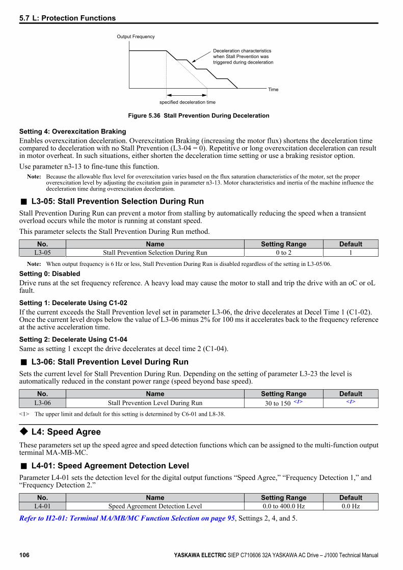
Output Frequency
Deceleration characteristics when Stall Prevention wastriggered during deceleration
Time
specified deceleration time
Figure 5.36 Stall Prevention During Deceleration
Setting 4: Overexcitation BrakingEnables overexcitation deceleration. Overexcitation Braking (increasing the motor flux) shortens the deceleration timecompared to deceleration with no Stall Prevention (L3-04 = 0). Repetitive or long overexcitation deceleration can resultin motor overheat. In such situations, either shorten the deceleration time setting or use a braking resistor option.Use parameter n3-13 to fine-tune this function.
Note: Because the allowable flux level for overexcitation varies based on the flux saturation characteristics of the motor, set the properoverexcitation level by adjusting the excitation gain in parameter n3-13. Motor characteristics and inertia of the machine influence thedeceleration time during overexcitation deceleration.
n L3-05: Stall Prevention Selection During RunStall Prevention During Run can prevent a motor from stalling by automatically reducing the speed when a transientoverload occurs while the motor is running at constant speed.This parameter selects the Stall Prevention During Run method.
No. Name Setting Range DefaultL3-05 Stall Prevention Selection During Run 0 to 2 1
Note: When output frequency is 6 Hz or less, Stall Prevention During Run is disabled regardless of the setting in L3-05/06.
Setting 0: DisabledDrive runs at the set frequency reference. A heavy load may cause the motor to stall and trip the drive with an oC or oLfault.
Setting 1: Decelerate Using C1-02If the current exceeds the Stall Prevention level set in parameter L3-06, the drive decelerates at Decel Time 1 (C1-02).Once the current level drops below the value of L3-06 minus 2% for 100 ms it accelerates back to the frequency referenceat the active acceleration time.
Setting 2: Decelerate Using C1-04Same as setting 1 except the drive decelerates at decel time 2 (C1-04).
n L3-06: Stall Prevention Level During RunSets the current level for Stall Prevention During Run. Depending on the setting of parameter L3-23 the level isautomatically reduced in the constant power range (speed beyond base speed).
No. Name Setting Range DefaultL3-06 Stall Prevention Level During Run 30 to 150 <1> <1>
<1> The upper limit and default for this setting is determined by C6-01 and L8-38.
u L4: Speed AgreeThese parameters set up the speed agree and speed detection functions which can be assigned to the multi-function outputterminal MA-MB-MC.
n L4-01: Speed Agreement Detection LevelParameter L4-01 sets the detection level for the digital output functions “Speed Agree,” “Frequency Detection 1,” and“Frequency Detection 2.”
No. Name Setting Range DefaultL4-01 Speed Agreement Detection Level 0.0 to 400.0 Hz 0.0 Hz
Refer to H2-01: Terminal MA/MB/MC Function Selection on page 95, Settings 2, 4, and 5.
5.7 L: Protection Functions
106 YASKAWA ELECTRIC SIEP C710606 32A YASKAWA AC Drive – J1000 Technical Manual
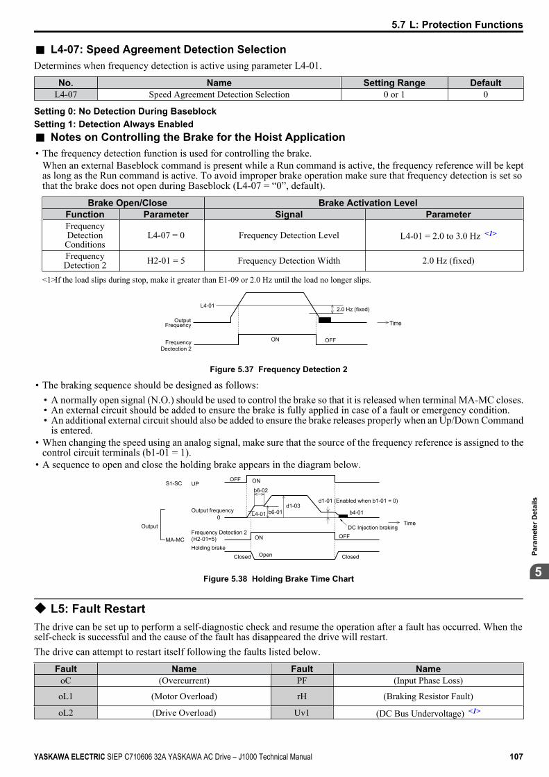
n L4-07: Speed Agreement Detection SelectionDetermines when frequency detection is active using parameter L4-01.
No. Name Setting Range DefaultL4-07 Speed Agreement Detection Selection 0 or 1 0
Setting 0: No Detection During BaseblockSetting 1: Detection Always Enabledn Notes on Controlling the Brake for the Hoist Application• The frequency detection function is used for controlling the brake.
When an external Baseblock command is present while a Run command is active, the frequency reference will be keptas long as the Run command is active. To avoid improper brake operation make sure that frequency detection is set sothat the brake does not open during Baseblock (L4-07 = “0”, default).
Brake Open/Close Brake Activation LevelFunction Parameter Signal ParameterFrequencyDetection
ConditionsL4-07 = 0 Frequency Detection Level L4-01 = 2.0 to 3.0 Hz <1>
FrequencyDetection 2 H2-01 = 5 Frequency Detection Width 2.0 Hz (fixed)
<1>If the load slips during stop, make it greater than E1-09 or 2.0 Hz until the load no longer slips.
2.0 Hz (fixed)L4-01
OFFON
TimeOutput Frequency
Frequency Dectection 2
Figure 5.37 Frequency Detection 2
• The braking sequence should be designed as follows:• A normally open signal (N.O.) should be used to control the brake so that it is released when terminal MA-MC closes.• An external circuit should be added to ensure the brake is fully applied in case of a fault or emergency condition.• An additional external circuit should also be added to ensure the brake releases properly when an Up/Down Command
is entered.• When changing the speed using an analog signal, make sure that the source of the frequency reference is assigned to the
control circuit terminals (b1-01 = 1).• A sequence to open and close the holding brake appears in the diagram below.
Time
UPS1-SCOFF
d1-03d1-01 (Enabled when b1-01 = 0)
L4-01 b4-01
OFFDC Injection braking
ON
ONMA-MCHolding brake
Output frequency0
Frequency Detection 2(H2-01=5)
Closed ClosedOpen
b6-02
b6-01
Output
Figure 5.38 Holding Brake Time Chart
u L5: Fault RestartThe drive can be set up to perform a self-diagnostic check and resume the operation after a fault has occurred. When theself-check is successful and the cause of the fault has disappeared the drive will restart.The drive can attempt to restart itself following the faults listed below.
Fault Name Fault NameoC (Overcurrent) PF (Input Phase Loss)
oL1 (Motor Overload) rH (Braking Resistor Fault)
oL2 (Drive Overload) Uv1 (DC Bus Undervoltage) <1>
5.7 L: Protection Functions
YASKAWA ELECTRIC SIEP C710606 32A YASKAWA AC Drive – J1000 Technical Manual 107
5
Para
met
er D
etai
ls
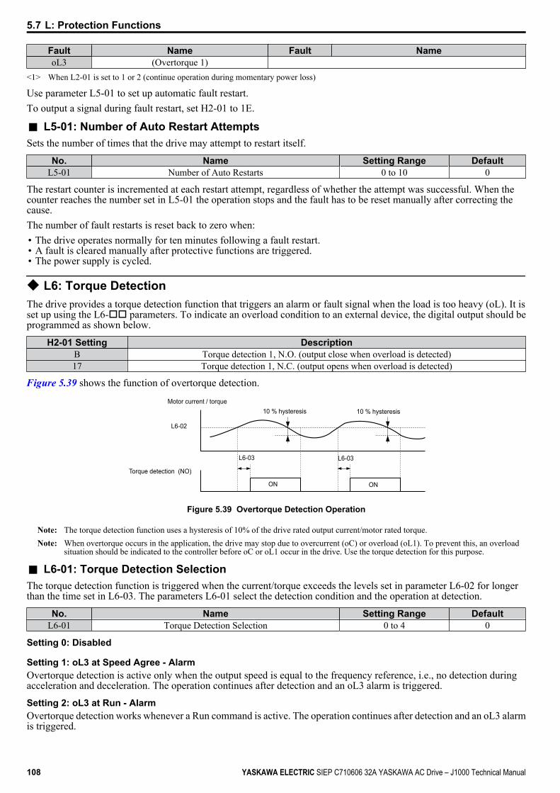
Fault Name Fault NameoL3 (Overtorque 1)
<1> When L2-01 is set to 1 or 2 (continue operation during momentary power loss)
Use parameter L5-01 to set up automatic fault restart.To output a signal during fault restart, set H2-01 to 1E.
n L5-01: Number of Auto Restart AttemptsSets the number of times that the drive may attempt to restart itself.
No. Name Setting Range DefaultL5-01 Number of Auto Restarts 0 to 10 0
The restart counter is incremented at each restart attempt, regardless of whether the attempt was successful. When thecounter reaches the number set in L5-01 the operation stops and the fault has to be reset manually after correcting thecause.The number of fault restarts is reset back to zero when:• The drive operates normally for ten minutes following a fault restart.• A fault is cleared manually after protective functions are triggered.• The power supply is cycled.
u L6: Torque DetectionThe drive provides a torque detection function that triggers an alarm or fault signal when the load is too heavy (oL). It isset up using the L6-oo parameters. To indicate an overload condition to an external device, the digital output should beprogrammed as shown below.
H2-01 Setting DescriptionB Torque detection 1, N.O. (output close when overload is detected)17 Torque detection 1, N.C. (output opens when overload is detected)
Figure 5.39 shows the function of overtorque detection.
Motor current / torque
L6-02
10 % hysteresis
Torque detection (NO)
L6-03
ON
L6-03
10 % hysteresis
ON
Figure 5.39 Overtorque Detection Operation
Note: The torque detection function uses a hysteresis of 10% of the drive rated output current/motor rated torque.Note: When overtorque occurs in the application, the drive may stop due to overcurrent (oC) or overload (oL1). To prevent this, an overload
situation should be indicated to the controller before oC or oL1 occur in the drive. Use the torque detection for this purpose.
n L6-01: Torque Detection SelectionThe torque detection function is triggered when the current/torque exceeds the levels set in parameter L6-02 for longerthan the time set in L6-03. The parameters L6-01 select the detection condition and the operation at detection.
No. Name Setting Range DefaultL6-01 Torque Detection Selection 0 to 4 0
Setting 0: Disabled
Setting 1: oL3 at Speed Agree - AlarmOvertorque detection is active only when the output speed is equal to the frequency reference, i.e., no detection duringacceleration and deceleration. The operation continues after detection and an oL3 alarm is triggered.
Setting 2: oL3 at Run - AlarmOvertorque detection works whenever a Run command is active. The operation continues after detection and an oL3 alarmis triggered.
5.7 L: Protection Functions
108 YASKAWA ELECTRIC SIEP C710606 32A YASKAWA AC Drive – J1000 Technical Manual
Setting 3: oL3 at Speed Agree - FaultOvertorque detection is active only when the output speed is equal to the frequency reference, i.e., no detection duringacceleration and deceleration. The operation is stopped and an oL3 fault is triggered.
Setting 4: oL3 at Run - FaultOvertorque detection works whenever a Run command is active. The operation is stopped and an oL3 fault is triggered.
n L6-02: Torque Detection LevelThese parameters the detection levels for the torque detection function.
No. Name Setting Range DefaultL6-02 Torque Detection Level 0 to 300% 150%
n L6-03: Torque Detection TimeThese parameters set the time that the levels set in L6-02 have to be exceeded before an alarm/fault is triggered.
No. Name Setting Range DefaultL6-03 Torque Detection time 0.0 to 10.0 s 0.1 s
u L8: Hardware Protectionn L8-01: Internal Dynamic Braking Resistor Protection Selection (ERF type)This parameter selects the dynamic braking resistor protection when using an optional heatsink mounted braking resistor(ERF type, 3% ED).
No. Name Setting Range DefaultL8-01 Internal Braking Resistor Protection 0 or 1 0
Setting 0: DisabledDisables the braking resistor protection. Use this setting for any braking option other than the Yaskawa ERF Type resistor.
Setting 1: EnabledEnables the protection for ERF type resistors.
n L8-05: Input Phase Loss Protection SelectionEnables or disables the input phase loss detection.
No. Name Setting Range DefaultL8-05 Input Phase Loss Detection Selection 0 or 1 1
Setting 0: Disabled
Setting 1: EnabledEnables the input phase loss detection. As detection is performed by measuring the DC bus ripple, a phase loss fault (PF)can also be triggered by power supply voltage imbalance or main circuit capacitor deterioration. Detection is disabledwhen:• The drive is decelerating.• No Run command is active.• Output current is less than or equal to 30% of the drive rated current.
n L8-10: Heatsink Cooling Fan Operation SelectionSelects the heatsink cooling fan operation.
No. Name Setting Range DefaultL8-10 Fan Operation Selection 0 or 1 0
Setting 0: Run with TimerThe fan is switched on when a Run command is active. It is switched off 60 s after the Run command has been released.Using this setting extends the fan lifetime.
Setting 1: Run alwaysThe fan runs whenever power is supplied to the drive.
5.7 L: Protection Functions
YASKAWA ELECTRIC SIEP C710606 32A YASKAWA AC Drive – J1000 Technical Manual 109
5
Para
met
er D
etai
ls

n L8-12: Ambient Temperature SettingIf the temperature where the drive is mounted is above the specified values, the drive rated current must be reduced foroptimal performance life. By setting the ambient temperature to parameter L8-12 and adjusting the installation methodsetting in L8-35, the drive rating automatically adapts to safe values.
No. Name Setting Range DefaultL8-12 Ambient Temperature Setting -10 to +50 °C 30 °C
n L8-18: Software CLA SelectionThe Software Current Limit (CLA) is a drive protection function that prevents output transistor failures caused by highcurrent. Parameter L8-18 enables or disables this function.
Note: This setting should not be changed unless absolutely necessary. For proper drive protection and operation leave the Software CLA functionenabled.
No. Name Setting Range DefaultL8-18 Software Current Limit Selection 0 or 1 1
Setting 0: DisabledThe drive may trip on an oC fault if the load is too heavy or the acceleration is too short.
Setting 1: EnabledWhen the soft CLA current level is reached, the drive reduces the output voltage in order to reduce the current. If thecurrent level drops below the Software CLA level, then normal operation will continue.
n L8-35: Installation Method SelectionSelects the type of installation and changes the drive overload (oL2) limits accordingly.
Note: 1. This parameter is not reset when the drive is initialized.2. The value is preset to the appropriate value when the drive is shipped. Change the value only when using Side-by-Side installation or
when mounting a standard drive with the heatsink outside the cabinet.
No. Name Setting Range DefaultL8-35 Installation Method Selection 0 to 3 0
Setting 0: IP20/Open-Chassis DriveMust be selected if an IP20/Open-Chassis drive is installed with minimal 30 mm space to the next drive or a cabinet wall.
Setting 1: Side-by-Side MountingMust be selected if drives are Side-by-Side mounted with a minimum space of 2 mm.
Setting 2: IP20/NEMA Type 1 DriveMust be selected if the drive has a IP20/NEMA Type 1 enclosure.
Setting 3: Finless Drive or External Heatsink InstallationMust be selected for finless drives or if a standard drive is mounted with the heatsink outside the cabinet.
n L8-38: Carrier Frequency Reduction SelectionThe drive can reduce the carrier frequency when the output current exceeds a certain level. This temporarily increases theoverload capability (oL2 detection) and the drive can run through transient load peaks without tripping.L8-38 selects the operation of the carrier frequency reduction function.
No. Name Setting Range Default
L8-38 Carrier Frequency Reduction Selection 0 to 2 Determined byo2-04
Setting 0: DisabledNo carrier frequency reduction at high current.
Setting 1: Enabled for Output Frequencies below 6 HzThe carrier frequency is reduced at speeds below 6 Hz when the current exceeds 100% of the drive rated current. The drivereturns to its normal carrier frequency when the current falls below 88% or the output frequency exceeds 7 Hz.
Setting 2: Enabled for Entire Frequency RangeThe carrier frequency is reduced at the following speeds:• Below 6 Hz when the current exceeds 100% of the drive rated current.• Above 7 Hz when the current exceeds 112% of the drive rated current.
5.7 L: Protection Functions
110 YASKAWA ELECTRIC SIEP C710606 32A YASKAWA AC Drive – J1000 Technical Manual

The drive uses the delay time of 0.5 s and a hysteresis of 12% when switching the carrier frequency back to the set value.
5.7 L: Protection Functions
YASKAWA ELECTRIC SIEP C710606 32A YASKAWA AC Drive – J1000 Technical Manual 111
5
Para
met
er D
etai
ls
5.8 n: Special AdjustmentsThe n parameters handle a variety of specialized adjustments and functions, including Hunting Prevention.
u n1: Hunting PreventionHunting Prevention keeps the drive from hunting as a result of low inertia and operating with light load.
n n1-02: Hunting Prevention Gain SettingSets the gain for the Hunting Prevention Function.
No. Name Setting Range Defaultn1-02 Hunting Prevention Gain Setting 0.00 to 2.50 1.00
Normally, n1-02 does not need to be changed, but adjustment may help under the following conditions:• If the motor vibrates while lightly loaded increase the gain by 0.1 until vibration ceases.• If the motor stalls decrease the gain by 0.1 until the stalling ceases.
u n3: Overexcitation DecelerationOverexcitation deceleration increases the flux during deceleration and allows shorter deceleration time settings than withnormal deceleration without the use of a braking resistor. Enabled by setting L3-04 = 4.Notes on Overexcitation Deceleration• As regenerative energy is mainly dissipated as heat in the motor, the motor temperature will rise if overexcitation
deceleration is applied frequently. In such cases, make sure the motor temperature does not exceed the maximumallowable value or consider using a braking resistor option instead.
• The drive decelerates at the active deceleration time. Make sure to set this time so that no overvoltage (ov) fault occurs.• When a Run command is entered during overexcitation deceleration, overexcitation operation is cancelled and the drive
will reaccelerate to the specified speed.• Do not use overexcitation deceleration in combination with a braking resistor option.Use parameter n3-13 for adjusting overexcitation deceleration.
n n3-13: Overexcitation Deceleration GainApplies a gain to the V/f pattern output value during overexcitation deceleration, thereby determining the level ofoverexcitation. The drive returns to the normal V/f value after the motor has stopped or when it is accelerating to thefrequency reference.
No. Name Setting Range Defaultn3-13 Overexcitation Deceleration Gain 1.00 to 1.40 1.10
The optimum setting for n3-13 depends on the motor flux saturation characteristics.• Increase the gain by 1.25 to 1.30 to improve the breaking power of overexcitation.• Reduce the value when the motor slip gets too high, which can trigger overcurrent (oC), motor overload (oL1), or drive
overload (oL2) faults.
5.8 n: Special Adjustments
112 YASKAWA ELECTRIC SIEP C710606 32A YASKAWA AC Drive – J1000 Technical Manual
5.9 o: Operator Related SettingsThese parameters concern the various functions and features of the digital operator.
u o1: Display Settings and SelectionsThese parameters determine how data is shown on the operator display.
n o1-02: User Monitor Selection after Power UpSelects which monitor parameter will be displayed upon power up. Defaulted to show the frequency reference when thedrive is first turned on.
No. Name Setting Range Defaulto1-02 User Monitor Selection after Power Up 1 to 4 1
Setting 1: Frequency Reference (U1-01)
Setting 2: Forward/Reverse
Setting 3: Output Frequency (U1-02)
Setting 4: Output Current (U1-03)
n o1-03: Digital Operator Display SelectionParameter o1-03 allows the programmer to change the units used in the following parameters and monitors:• U1-01: frequency reference• U1-02: output frequency• d1-01 to d1-08: frequency references
No. Name Setting Range Defaulto1-03 Digital Operator Display Selection 0 to 1 0
Setting 0: HzThe frequency reference and monitors are displayed in Hz with a resolution of 0.01 Hz.
Setting 1: %The frequency reference and monitors are displayed as a percentage with a resolution of 0.01%. 100% is equal to themaximum output frequency.
u o2: Operator Key SelectionsThese parameters determine the functions assigned to the operator keys.
n o2-02: STOP Key Function SelectionSelects if the STOP key on the digital operator can be used to stop the operation when the drive is controlled from a remotesource (i.e., not from digital operator).
No. Name Setting Range Defaulto2-02 STOP Key Function Selection 0 or 1 1
Setting 0: DisabledThe STOP key has no function when the drive is controlled by a source other than the digital operator. The drive can onlybe stopped from the Run command source that has been selected.
Setting 1: EnabledThe STOP key can be used to terminate the operation, even if the Run command source is not assigned to the digitaloperator. If operation has been interrupted by pressing the STOP key, the Run command must be cycled to restart the drive.
n o2-04: Drive Model SelectionParameter o2-04 matches the control board to the drive hardware. Proper setting of o2-04 is important for optimalperformance and proper protection for the drive hardware. This parameter is configured at the factory and does not normallyrequire adjustment in the field. It is available primarily to accommodate control board replacement in the event of damage.
5.9 o: Operator Related Settings
YASKAWA ELECTRIC SIEP C710606 32A YASKAWA AC Drive – J1000 Technical Manual 113
5
Para
met
er D
etai
ls

No. Name Setting Range Default
o2-04 Drive Model Selection - Depending on drivesize
Note: 1. Refer to Defaults by Drive Capacity (o2-04) and ND/HD (C6-01) on page 185 for a list of o2-04 settings and parameters that changedepending on the drive model selection.
2. Drive performance will suffer if the correct drive capacity is not set to o2-04, and protective functions will fail to operate properly.
n o2-05: Frequency Reference Setting Method SelectionDetermines if the ENTER key must be used to input a frequency reference from the digital operator.
No. Name Setting Range Defaulto2-05 Frequency Reference Setting Method Selection 0 or 1 0
Setting 0: ENTER Key RequiredEvery change in the frequency reference setting on the digital operator has to be finalized by pressing the ENTER keybefore it becomes effective.
Setting 1: ENTER Key Not RequiredThe output frequency changes immediately when the reference is changed by the UP and DOWN key on the digital operator.The ENTER key does not need to be pressed. The frequency reference is saved five seconds after the Up or DOWN keyhas been released.
n o2-06: Operation Selection when LED Operator is DisconnectedDetermines if the drive will stop when an external LED operator (JVOP-182) is removed in LOCAL mode or with b1-02set to 0.
No. Name Setting Range Defaulto2-06 Digital Operator Disconnection Operation 0 or 1 0
Setting 0: Continue OperationThe operation is continued.
Setting 1: Trigger a FaultThe operation is stopped and an “oPr” fault is triggered. The motor coasts to stop.
n o2-09: Initialization Specification SelectionThis parameter sets the regional specifications for the drive and should not be changed.
u o3: Copy FunctionUse o3 parameters to Read, Copy, and Verify the parameter settings to and from the drive using an LED operator (option).
n o3-01 Copy Function SelectionParameter o3-01 selects the copy function operation.
No. Name Setting Range Defaulto3-01 Copy Function Selection 0 to 3 0
0: No Action1: READAll parameters are copied from the drive to the LED operator.
2: WRITEAll parameters are copied from the LED operator to the drive.
3: VERIFYParameter settings in the drive are compared to those in the LED operator.
Note: When using the copy function, the drive model number (o2-04) and the software number (U1-14) must match or an error will occur.
n o3-02 Copy Function READ PermissionParameter o3-02 can be used to prevent accidentally overwriting the data stored in the operator.
No. Name Setting Range Defaulto3-02 Copy Function READ Permission 0, 1 0
5.9 o: Operator Related Settings
114 YASKAWA ELECTRIC SIEP C710606 32A YASKAWA AC Drive – J1000 Technical Manual

0: READ ProhibitedThe data in the operator are write protected. The READ operation cannot be performed.
1: READ PermittedThe data in the operator are not write protected. The READ operation can be performed.
u o4: Maintenance Monitor Settingsn o4-01: Accumulated Operation Time SettingParameter o4-01 sets the cumulative operation time and allows the user to set the starting value of the accumulated operationtime displayed in monitor U4-01.
Note: The value in o4-01 is set in 10 h units. For example, a setting of 30 will set the cumulative operation time counter to 300 h. 300 h will alsobe displayed in monitor U4-01.
No. Name Setting Range Defaulto4-01 Accumulated Operation Time Setting 0 to 9999 0
n o4-02: Accumulated Operation Time SelectionSelects the conditions for what is to be considered “accumulated operation time.” Accumulated operation time is displayedin U4-01.
No. Name Setting Range Defaulto4-02 Accumulated Operation Time Selection 0 or 1 0
Setting 0: Power On TimeThe drive logs the time it is connected to a power supply, no matter if the motor is running or not.
Setting 1: Run TimeThe drive logs the time that the output is active, i.e., whenever a Run command is active (even if the motor is not rotating)or a voltage is output.
n o4-03: Cooling Fan Maintenance SettingSets the value of the cooling fan operation time base value used for the maintenance value displayed in U4-04. Be sure toreset this parameter back to 0 if the cooling fan is replaced.
Note: 1. The value in o4-03 is set in 10 h units.2. The actual maintenance time depends on the environment the drive is used in.
No. Name Setting Range Defaulto4-03 Cooling Fan Operation Time 0 to 9999 0
n o4-05: Capacitor Maintenance SettingSets value of the maintenance monitor for the DC bus capacitors displayed in U4-05 as a percentage of the total expectedperformance life. This value should be reset to 0 when the DC bus capacitors have been replaced.
Note: The actual maintenance time will depend on the environment the drive is used in.
No. Name Setting Range Defaulto4-05 Capacitor Maintenance Setting 0 to 150% 0%
n o4-07: DC Bus Pre-charge Relay Maintenance SettingSets the value of the softcharge bypass relay maintenance time displayed in U4-06 as a percentage of the total expectedperformance life. This value should be reset to 0 when the relay has been replaced.
Note: The maintenance actual time depends on the environment the drive is used in.
No. Name Setting Range Defaulto4-07 DC Bus Pre-charge Relay Maintenance Setting 0 to 150% 0%
n o4-09: IGBT Maintenance SettingSets the value of the IGBT maintenance time displayed in U4-07 as a percentage of the total expected performance life.This value should be reset to 0 when the IGBTs have been replaced.
Note: The actual maintenance time depends on the environment the drive is used in.
No. Name Setting Range Defaulto4-09 IGBT Maintenance Setting 0 to 150% 0%
5.9 o: Operator Related Settings
YASKAWA ELECTRIC SIEP C710606 32A YASKAWA AC Drive – J1000 Technical Manual 115
5
Para
met
er D
etai
ls
n o4-11: U2 InitializationWhen the drive is initialized, the fault history monitors (U2-oo) are not reset. Parameter o4-11 can be used to initializethem.
No. Name Setting Range Defaulto4-11 U2 Initialization 0 or 1 0
Setting 0: No ActionThe drive keeps a record of the fault history.
Setting 1: Reset Fault DataResets the data for the U2-oo monitors. Once o4-11 is set to 1 and the ENTER key is pressed, the fault data are erasedand the display returns to 0.
5.9 o: Operator Related Settings
116 YASKAWA ELECTRIC SIEP C710606 32A YASKAWA AC Drive – J1000 Technical Manual
5.10 U: Monitor ParametersMonitor parameters let the user view various aspects of drive performance as it is shown on the operator display.Some monitors can be output from terminal AM by assigning the specific monitor parameter number to H4-01. Refer to H4-01: Multi-Function Analog Terminal AM Monitor Selection on page 101 for details on assigning functions to theanalog output.
u U1: Operation Status MonitorsStatus monitors display drive status like output frequency, current etc. Refer to U1: Operation Status Monitors on page183 for a complete list of U1-oo monitors and descriptions.
u U2: Fault HistoryThe fault history monitors can be used to view the current and the last occurred fault. Refer to U2: Fault History on page184 for a list of U2-oo monitors and descriptions.U2-oo monitors are not reset when the drive is initialized. Refer to o4-11: U2 Initialization on page 116 for instructionsto initialize the fault history.
u U4: Maintenance MonitorsMaintenance monitors show:• Runtime data of the drive.• Maintenance data and replacement information for various drive components.• Highest peak current that has occurred and output frequency at the time the peak current occurred.Refer to U4: Maintenance Monitors on page 184 for a complete list of U4-oo monitors and descriptions.
5.10 U: Monitor Parameters
YASKAWA ELECTRIC SIEP C710606 32A YASKAWA AC Drive – J1000 Technical Manual 117
5
Para
met
er D
etai
ls

5.10 U: Monitor Parameters
This Page Intentionally Blank
118 YASKAWA ELECTRIC SIEP C710606 32A YASKAWA AC Drive – J1000 Technical Manual
TroubleshootingThis chapter provides descriptions of the drive faults, alarms, errors, related displays, and possiblesolutions. This chapter can also serve as a reference guide for tuning the drive during a trial run.
6.1 SECTION SAFETY..........................................................................................1206.2 MOTOR PERFORMANCE FINE TUNING......................................................1226.3 DRIVE ALARMS, FAULTS, AND ERRORS...................................................1236.4 FAULT DETECTION.......................................................................................1256.5 ALARM DETECTION......................................................................................1316.6 OPERATOR PROGRAMMING ERRORS.......................................................1346.7 DIAGNOSING AND RESETTING FAULTS....................................................1356.8 TROUBLESHOOTING WITHOUT FAULT DISPLAY.....................................136
6
YASKAWA ELECTRIC SIEP C710606 32A YASKAWA AC Drive – J1000 Technical Manual 119
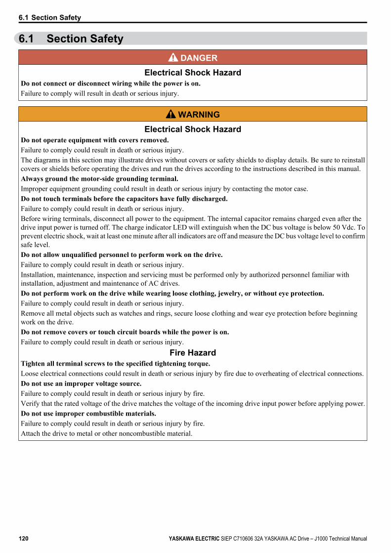
6.1 Section Safety DANGER
Electrical Shock HazardDo not connect or disconnect wiring while the power is on.Failure to comply will result in death or serious injury.
WARNINGElectrical Shock Hazard
Do not operate equipment with covers removed.Failure to comply could result in death or serious injury.The diagrams in this section may illustrate drives without covers or safety shields to display details. Be sure to reinstallcovers or shields before operating the drives and run the drives according to the instructions described in this manual.Always ground the motor-side grounding terminal.Improper equipment grounding could result in death or serious injury by contacting the motor case.Do not touch terminals before the capacitors have fully discharged.Failure to comply could result in death or serious injury.Before wiring terminals, disconnect all power to the equipment. The internal capacitor remains charged even after thedrive input power is turned off. The charge indicator LED will extinguish when the DC bus voltage is below 50 Vdc. Toprevent electric shock, wait at least one minute after all indicators are off and measure the DC bus voltage level to confirmsafe level.Do not allow unqualified personnel to perform work on the drive.Failure to comply could result in death or serious injury.Installation, maintenance, inspection and servicing must be performed only by authorized personnel familiar withinstallation, adjustment and maintenance of AC drives.Do not perform work on the drive while wearing loose clothing, jewelry, or without eye protection.Failure to comply could result in death or serious injury.Remove all metal objects such as watches and rings, secure loose clothing and wear eye protection before beginningwork on the drive.Do not remove covers or touch circuit boards while the power is on.Failure to comply could result in death or serious injury.
Fire HazardTighten all terminal screws to the specified tightening torque.Loose electrical connections could result in death or serious injury by fire due to overheating of electrical connections.Do not use an improper voltage source.Failure to comply could result in death or serious injury by fire.Verify that the rated voltage of the drive matches the voltage of the incoming drive input power before applying power.Do not use improper combustible materials.Failure to comply could result in death or serious injury by fire.Attach the drive to metal or other noncombustible material.
6.1 Section Safety
120 YASKAWA ELECTRIC SIEP C710606 32A YASKAWA AC Drive – J1000 Technical Manual
NOTICEObserve proper electrostatic discharge procedures (ESD) when handling the drive and circuit boards.Failure to comply may result in ESD damage to the drive circuitry.Never connect or disconnect the motor from the drive while the drive is outputting voltage.Improper equipment sequencing could result in damage to the drive.Do not use unshielded cable for control wiring.Failure to comply may cause electrical interference resulting in poor system performance. Use shielded twisted-pair wiresand ground the shield to the ground terminal of the drive.Do not allow unqualified personnel to use the product.Failure to comply could result in damage to the drive or braking circuit.Carefully review instruction manual TOBPC72060000 when connecting a braking option to the drive.Do not modify the drive circuitry.Failure to comply could result in damage to the drive and will void warranty.Yaskawa is not responsible for modification of the product made by the user.Check all the wiring after installing the drive and connecting other devices to ensure that all connections arecorrect.Failure to comply could result in damage to the drive.
6.1 Section Safety
YASKAWA ELECTRIC SIEP C710606 32A YASKAWA AC Drive – J1000 Technical Manual 121
6
Trou
bles
hoot
ing
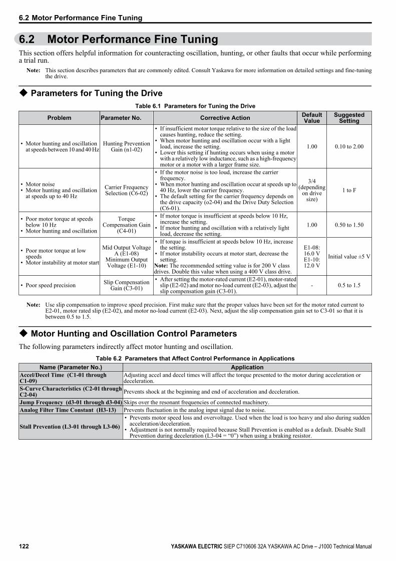
6.2 Motor Performance Fine TuningThis section offers helpful information for counteracting oscillation, hunting, or other faults that occur while performinga trial run.
Note: This section describes parameters that are commonly edited. Consult Yaskawa for more information on detailed settings and fine-tuningthe drive.
u Parameters for Tuning the DriveTable 6.1 Parameters for Tuning the Drive
Problem Parameter No. Corrective Action DefaultValue
SuggestedSetting
• Motor hunting and oscillationat speeds between 10 and 40 Hz
Hunting PreventionGain (n1-02)
• If insufficient motor torque relative to the size of the loadcauses hunting, reduce the setting.
• When motor hunting and oscillation occur with a lightload, increase the setting.
• Lower this setting if hunting occurs when using a motorwith a relatively low inductance, such as a high-frequencymotor or a motor with a larger frame size.
1.00 0.10 to 2.00
• Motor noise• Motor hunting and oscillation
at speeds up to 40 HzCarrier FrequencySelection (C6-02)
• If the motor noise is too loud, increase the carrierfrequency.
• When motor hunting and oscillation occur at speeds up to40 Hz, lower the carrier frequency.
• The default setting for the carrier frequency depends onthe drive capacity (o2-04) and the Drive Duty Selection(C6-01).
3/4(depending
on drivesize)
1 to F
• Poor motor torque at speedsbelow 10 Hz
• Motor hunting and oscillation
TorqueCompensation Gain
(C4-01)
• If motor torque is insufficient at speeds below 10 Hz,increase the setting.
• If motor hunting and oscillation with a relatively lightload, decrease the setting.
1.00 0.50 to 1.50
• Poor motor torque at lowspeeds
• Motor instability at motor start
Mid Output VoltageA (E1-08)
Minimum OutputVoltage (E1-10)
• If torque is insufficient at speeds below 10 Hz, increasethe setting.
• If motor instability occurs at motor start, decrease thesetting.
Note: The recommended setting value is for 200 V classdrives. Double this value when using a 400 V class drive.
E1-08:16.0 VE1-10:12.0 V
Initial value ±5 V
• Poor speed precision Slip CompensationGain (C3-01)
• After setting the motor-rated current (E2-01), motor-ratedslip (E2-02) and motor no-load current (E2-03), adjust theslip compensation gain (C3-01).
- 0.5 to 1.5
Note: Use slip compensation to improve speed precision. First make sure that the proper values have been set for the motor rated current toE2-01, motor rated slip (E2-02), and motor no-load current (E2-03). Next, adjust the slip compensation gain set to C3-01 so that it isbetween 0.5 to 1.5.
u Motor Hunting and Oscillation Control ParametersThe following parameters indirectly affect motor hunting and oscillation.
Table 6.2 Parameters that Affect Control Performance in ApplicationsName (Parameter No.) Application
Accel/Decel Time (C1-01 throughC1-09)
Adjusting accel and decel times will affect the torque presented to the motor during acceleration ordeceleration.
S-Curve Characteristics (C2-01 throughC2-04) Prevents shock at the beginning and end of acceleration and deceleration.
Jump Frequency (d3-01 through d3-04) Skips over the resonant frequencies of connected machinery.Analog Filter Time Constant (H3-13) Prevents fluctuation in the analog input signal due to noise.
Stall Prevention (L3-01 through L3-06)• Prevents motor speed loss and overvoltage. Used when the load is too heavy and also during sudden
acceleration/deceleration.• Adjustment is not normally required because Stall Prevention is enabled as a default. Disable Stall
Prevention during deceleration (L3-04 = “0”) when using a braking resistor.
6.2 Motor Performance Fine Tuning
122 YASKAWA ELECTRIC SIEP C710606 32A YASKAWA AC Drive – J1000 Technical Manual

6.3 Drive Alarms, Faults, and Errors
u Types of Alarms, Faults, and ErrorsCheck the LED operator for information about possible faults if the drive or motor fails to operate. Refer to Using the Digital LED Operator on page 54.If problems occur that are not covered in this manual, contact the nearest Yaskawa representative with the followinginformation:• Drive model• Software version• Date of purchase• Description of the problemTable 6.3 contains descriptions of the various types of alarms, faults, and errors that may occur while operating the drive.Contact Yaskawa in the event of drive failure.
Table 6.3 Types of Alarms, Faults, and ErrorsType Drive Responses to Alarms, Faults, and Errors
Faults
When the drive detects a fault:• The digital operator displays text that indicates the specific fault and the ALM indicator LED remains lit until the fault
is reset.• The fault interrupts drive output and the motor coasts to a stop.• Depending on the setting, the drive and motor may stop via different methods than listed.• If a digital output is programmed for fault output (H2-01 = E), it will close if a fault occurs.When the drive detects a fault, it will remain inoperable until that fault has been reset. Refer to Fault Reset Methods on page 135.
Minor Faults andAlarms
When the drive detects an alarm or a minor fault:• The digital operator displays text that indicates the specific alarm or minor fault and the ALM indicator LED flashes.• The motor does not stop.• The multi-function contact output closes if set to be tripped by a minor fault (H2-01 = 10), but not by an alarm.• The digital operator displays text indicating a specific alarm and ALM indicator LED flashes.Remove the cause of an alarm or minor fault to automatically reset.
Operation Errors
When parameter settings conflict with one another or do not match hardware settings (such as with an option unit), it resultsin an operation error.When the drive detects an operation error:• The digital operator displays text that indicates the specific error.• The multi-function contact output does not operate.When the drive detects an operation error, it will not operate the motor until the error has been reset. Correct the settingsthat caused the operation error to reset.
u Alarm and Error Displaysn FaultsWhen the drive detects a fault, the ALM indicator LEDs remain lit without flashing. If the LEDs flash, the drive hasdetected a minor fault or alarm. Refer to Minor Faults and Alarms on page 124 for more information. Conditions suchas overvoltage or external faults can trip both faults and minor faults, therefore it is important to note whether the LEDsremain lit or if the LEDs flash.
Table 6.4 Fault DisplaysLED Operator
Display Name Page
CE MEMOBUS/ModbusCommunication Error 125
CoF Current Offset Fault 125
or CPF00 orCPF01
<1>
CPF11 – RAM Fault 125CPF12 – FLASH Memory Fault 125CPF14 – Control Circuit Fault 125CPF17 – Timing Fault 125CPF18 – Control Circuit Fault 125
CPF02 A/D Conversion Error 125
CPF06Drive specification mismatch duringTerminal Board or Control Boardreplacement
125
CPF08 EEPROM Serial CommunicationsFault 125
or CPF20 orCPF21
<2>
RAM Fault 125FLASH Memory Fault 125Watchdog Circuit Exception 125Clock Fault 125
LED OperatorDisplay Name Page
CPF22 A/D Conversion Error 126CPF23 PWM Feedback Data Fault 126CPF24 Drive Capacity Signal Fault 126
EF0 Option Unit External Fault 126
to EF1 toEF5
External Fault (input terminal S1 toS5) 126
Err EEPROM Write Error 126oC Overcurrent 126
oFA01 Option Disconnected 127oH1 Heatsink Overheat 127oL1 Motor Overload 127oL2 Drive Overload 128oL3 Overtorque Detection 1 128oPr Operator Connection Fault 128ov Overvoltage 132PF Input Phase Loss 129rH Dynamic Braking Resistor 129
6.3 Drive Alarms, Faults, and Errors
YASKAWA ELECTRIC SIEP C710606 32A YASKAWA AC Drive – J1000 Technical Manual 123
6
Trou
bles
hoot
ing
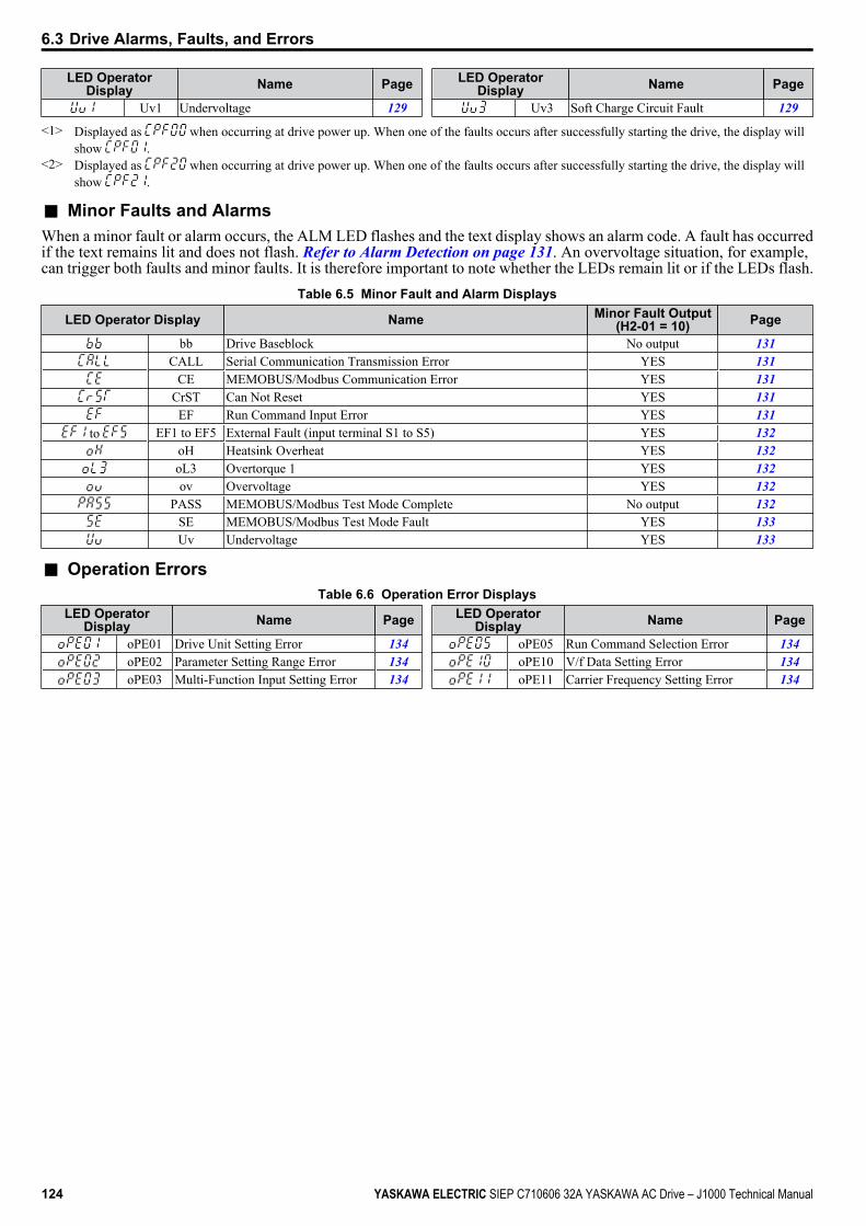
LED OperatorDisplay Name Page
Uv1 Undervoltage 129
LED OperatorDisplay Name Page
Uv3 Soft Charge Circuit Fault 129
<1> Displayed as when occurring at drive power up. When one of the faults occurs after successfully starting the drive, the display willshow .
<2> Displayed as when occurring at drive power up. When one of the faults occurs after successfully starting the drive, the display willshow .
n Minor Faults and AlarmsWhen a minor fault or alarm occurs, the ALM LED flashes and the text display shows an alarm code. A fault has occurredif the text remains lit and does not flash. Refer to Alarm Detection on page 131. An overvoltage situation, for example,can trigger both faults and minor faults. It is therefore important to note whether the LEDs remain lit or if the LEDs flash.
Table 6.5 Minor Fault and Alarm Displays
LED Operator Display Name Minor Fault Output(H2-01 = 10) Page
bb Drive Baseblock No output 131CALL Serial Communication Transmission Error YES 131
CE MEMOBUS/Modbus Communication Error YES 131CrST Can Not Reset YES 131EF Run Command Input Error YES 131
to EF1 to EF5 External Fault (input terminal S1 to S5) YES 132oH Heatsink Overheat YES 132oL3 Overtorque 1 YES 132ov Overvoltage YES 132
PASS MEMOBUS/Modbus Test Mode Complete No output 132SE MEMOBUS/Modbus Test Mode Fault YES 133Uv Undervoltage YES 133
n Operation ErrorsTable 6.6 Operation Error Displays
LED OperatorDisplay Name Page
oPE01 Drive Unit Setting Error 134oPE02 Parameter Setting Range Error 134oPE03 Multi-Function Input Setting Error 134
LED OperatorDisplay Name Page
oPE05 Run Command Selection Error 134oPE10 V/f Data Setting Error 134oPE11 Carrier Frequency Setting Error 134
6.3 Drive Alarms, Faults, and Errors
124 YASKAWA ELECTRIC SIEP C710606 32A YASKAWA AC Drive – J1000 Technical Manual
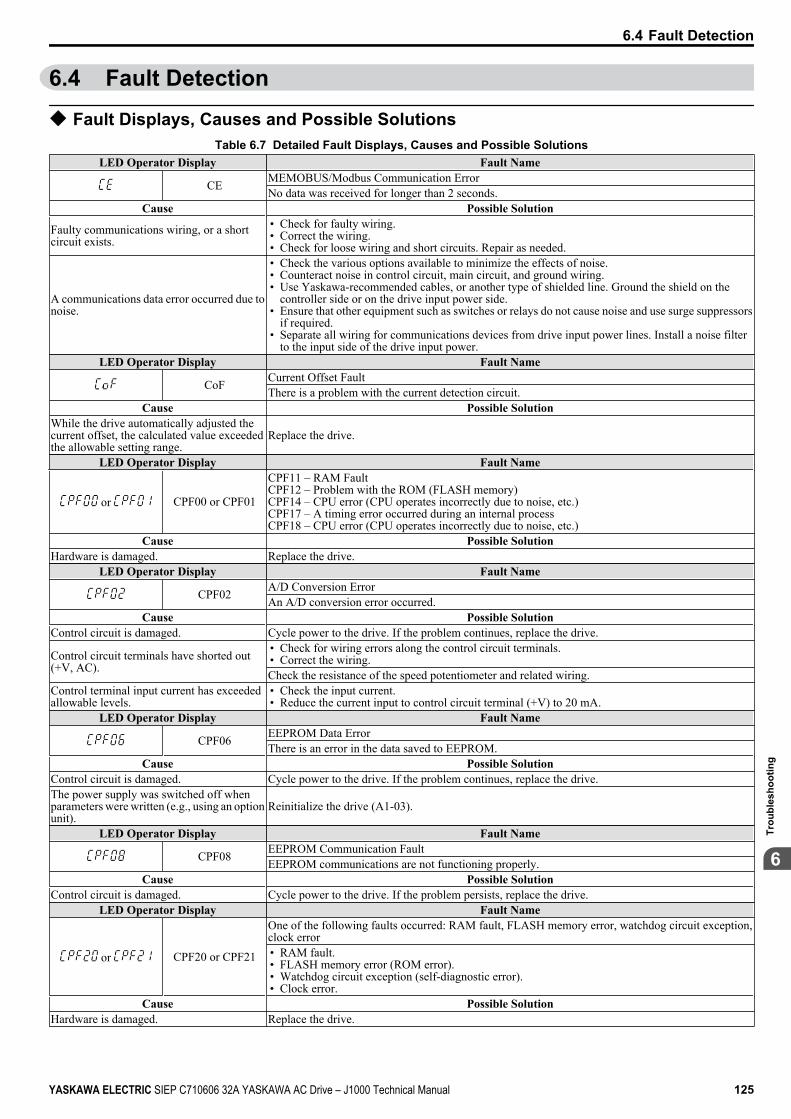
6.4 Fault Detection
u Fault Displays, Causes and Possible SolutionsTable 6.7 Detailed Fault Displays, Causes and Possible Solutions
LED Operator Display Fault Name
CE MEMOBUS/Modbus Communication ErrorNo data was received for longer than 2 seconds.
Cause Possible Solution
Faulty communications wiring, or a shortcircuit exists.
• Check for faulty wiring.• Correct the wiring.• Check for loose wiring and short circuits. Repair as needed.
A communications data error occurred due tonoise.
• Check the various options available to minimize the effects of noise.• Counteract noise in control circuit, main circuit, and ground wiring.• Use Yaskawa-recommended cables, or another type of shielded line. Ground the shield on the
controller side or on the drive input power side.• Ensure that other equipment such as switches or relays do not cause noise and use surge suppressors
if required.• Separate all wiring for communications devices from drive input power lines. Install a noise filter
to the input side of the drive input power.LED Operator Display Fault Name
CoF Current Offset FaultThere is a problem with the current detection circuit.
Cause Possible SolutionWhile the drive automatically adjusted thecurrent offset, the calculated value exceededthe allowable setting range.
Replace the drive.
LED Operator Display Fault Name
or CPF00 or CPF01
CPF11 – RAM FaultCPF12 – Problem with the ROM (FLASH memory)CPF14 – CPU error (CPU operates incorrectly due to noise, etc.)CPF17 – A timing error occurred during an internal processCPF18 – CPU error (CPU operates incorrectly due to noise, etc.)
Cause Possible SolutionHardware is damaged. Replace the drive.
LED Operator Display Fault Name
CPF02 A/D Conversion ErrorAn A/D conversion error occurred.
Cause Possible SolutionControl circuit is damaged. Cycle power to the drive. If the problem continues, replace the drive.
Control circuit terminals have shorted out(+V, AC).
• Check for wiring errors along the control circuit terminals.• Correct the wiring.Check the resistance of the speed potentiometer and related wiring.
Control terminal input current has exceededallowable levels.
• Check the input current.• Reduce the current input to control circuit terminal (+V) to 20 mA.
LED Operator Display Fault Name
CPF06 EEPROM Data ErrorThere is an error in the data saved to EEPROM.
Cause Possible SolutionControl circuit is damaged. Cycle power to the drive. If the problem continues, replace the drive.The power supply was switched off whenparameters were written (e.g., using an optionunit).
Reinitialize the drive (A1-03).
LED Operator Display Fault Name
CPF08 EEPROM Communication FaultEEPROM communications are not functioning properly.
Cause Possible SolutionControl circuit is damaged. Cycle power to the drive. If the problem persists, replace the drive.
LED Operator Display Fault Name
or CPF20 or CPF21
One of the following faults occurred: RAM fault, FLASH memory error, watchdog circuit exception,clock error• RAM fault.• FLASH memory error (ROM error).• Watchdog circuit exception (self-diagnostic error).• Clock error.
Cause Possible SolutionHardware is damaged. Replace the drive.
6.4 Fault Detection
YASKAWA ELECTRIC SIEP C710606 32A YASKAWA AC Drive – J1000 Technical Manual 125
6
Trou
bles
hoot
ing
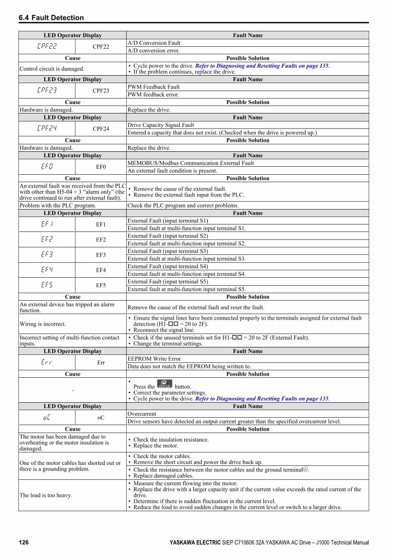
LED Operator Display Fault Name
CPF22 A/D Conversion FaultA/D conversion error.
Cause Possible Solution
Control circuit is damaged. • Cycle power to the drive. Refer to Diagnosing and Resetting Faults on page 135.• If the problem continues, replace the drive.
LED Operator Display Fault Name
CPF23 PWM Feedback FaultPWM feedback error.
Cause Possible SolutionHardware is damaged. Replace the drive.
LED Operator Display Fault Name
CPF24 Drive Capacity Signal FaultEntered a capacity that does not exist. (Checked when the drive is powered up.)
Cause Possible SolutionHardware is damaged. Replace the drive.
LED Operator Display Fault Name
EF0 MEMOBUS/Modbus Communication External FaultAn external fault condition is present.
Cause Possible SolutionAn external fault was received from the PLCwith other than H5-04 = 3 “alarm only” (thedrive continued to run after external fault).
• Remove the cause of the external fault.• Remove the external fault input from the PLC.
Problem with the PLC program. Check the PLC program and correct problems.LED Operator Display Fault Name
EF1 External Fault (input terminal S1)External fault at multi-function input terminal S1.
EF2 External Fault (input terminal S2)External fault at multi-function input terminal S2.
EF3 External Fault (input terminal S3)External fault at multi-function input terminal S3.
EF4 External Fault (input terminal S4)External fault at multi-function input terminal S4.
EF5 External Fault (input terminal S5)External fault at multi-function input terminal S5.
Cause Possible SolutionAn external device has tripped an alarmfunction. Remove the cause of the external fault and reset the fault.
Wiring is incorrect.• Ensure the signal lines have been connected properly to the terminals assigned for external fault
detection (H1-oo = 20 to 2F).• Reconnect the signal line.
Incorrect setting of multi-function contactinputs.
• Check if the unused terminals set for H1-oo = 20 to 2F (External Fault).• Change the terminal settings.
LED Operator Display Fault Name
Err EEPROM Write ErrorData does not match the EEPROM being written to.
Cause Possible Solution
-•
Press the button.• Correct the parameter settings.• Cycle power to the drive. Refer to Diagnosing and Resetting Faults on page 135.
LED Operator Display Fault Name
oC OvercurrentDrive sensors have detected an output current greater than the specified overcurrent level.
Cause Possible SolutionThe motor has been damaged due tooverheating or the motor insulation isdamaged.
• Check the insulation resistance.• Replace the motor.
One of the motor cables has shorted out orthere is a grounding problem.
• Check the motor cables.• Remove the short circuit and power the drive back up.• Check the resistance between the motor cables and the ground terminal .• Replace damaged cables.
The load is too heavy.
• Measure the current flowing into the motor.• Replace the drive with a larger capacity unit if the current value exceeds the rated current of the
drive.• Determine if there is sudden fluctuation in the current level.• Reduce the load to avoid sudden changes in the current level or switch to a larger drive.
6.4 Fault Detection
126 YASKAWA ELECTRIC SIEP C710606 32A YASKAWA AC Drive – J1000 Technical Manual
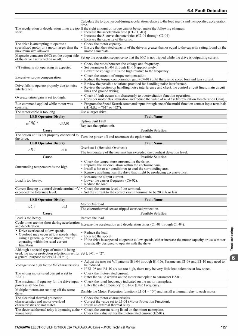
The acceleration or deceleration times are tooshort.
Calculate the torque needed during acceleration relative to the load inertia and the specified accelerationtime.If the right amount of torque cannot be set, make the following changes:• Increase the acceleration time (C1-01, -03)• Increase the S-curve characteristics (C2-01 through C2-04)• Increase the capacity of the drive.
The drive is attempting to operate aspecialized motor or a motor larger than themaximum size allowed.
• Check the motor capacity.• Ensure that the rated capacity of the drive is greater than or equal to the capacity rating found on the
motor nameplate.Magnetic contactor (MC) on the output sideof the drive has turned on or off. Set up the operation sequence so that the MC is not tripped while the drive is outputting current.
V/f setting is not operating as expected.• Check the ratios between the voltage and frequency.• Set parameter E1-04 through E1-10 appropriately.• Lower the voltage if it is too high relative to the frequency.
Excessive torque compensation. • Check the amount of torque compensation.• Reduce the torque compensation gain (C4-01) until there is no speed loss and less current.
Drive fails to operate properly due to noiseinterference.
• Review the possible solutions provided for handling noise interference.• Review the section on handling noise interference and check the control circuit lines, main circuit
lines and ground wiring.
Overexcitation gain is set too high. • Check if fault occurs simultaneously to overexcitation function operation.• Consider motor flux saturation and reduce the value of n3-13 (Overexcitation Deceleration Gain).
Run command applied while motor wascoasting.
• Program the Speed Search command input through one of the multi-function contact input terminals(H1-oo = “61” or “62”).
The motor cable is too long Use a larger drive.LED Operator Display Fault Name
oFA01 Option Unit FaultReplace the option unit.
Cause Possible SolutionThe option unit is not properly connected tothe drive. Turn the power off and reconnect the option unit.
LED Operator Display Fault Name
oH1 Overheat 1 (Heatsink Overheat)The temperature of the heatsink has exceeded the overheat detection level.
Cause Possible Solution
Surrounding temperature is too high.• Check the temperature surrounding the drive.• Improve the air circulation within the enclosure panel.• Install a fan or air conditioner to cool the surrounding area.• Remove anything near the drive that might be producing excessive heat.
Load is too heavy.• Measure the output current.• Lower the carrier frequency (C6-02).• Reduce the load.
Current flowing to control circuit terminal +Vexceeded the tolerance level.
• Check the current level of the terminal.• Set the current to the control circuit terminal to be 20 mA or less.
LED Operator Display Fault Name
oL1 Motor OverloadThe electrothermal sensor tripped overload protection.
Cause Possible SolutionLoad is too heavy. Reduce the load.Cycle times are too short during accelerationand deceleration. Increase the acceleration and deceleration times (C1-01 through C1-04).
• Drive overloaded at low speeds.• Overload may occur at low speeds when
using a general-purpose motor, even ifoperating within the rated currentlimitation.
• Reduce the load.• Increase the speed.• If the drive is supposed to operate at low speeds, either increase the motor capacity or use a motor
specifically designed to operate with the drive.
Although a special type of motor is beingused, the motor protection selection is set fora general-purpose motor (L1-01 = 1).
Set L1-01 = “2”.
Voltage is too high for the V/f characteristics.• Adjust the user set V/f patterns (E1-04 through E1-10). Parameters E1-08 and E1-10 may need to
be reduced.• If E1-08 and E1-10 are set too high, there may be very little load tolerance at low speed.
The wrong motor-rated current is set to E2-01.
• Check the motor-rated current.• Enter the value written on the motor nameplate to parameter E2-01.
The maximum frequency for the drive inputpower is set too low.
• Check the rated frequency indicated on the motor nameplate.• Enter the rated frequency to E1-06 (Base Frequency).
Multiple motors are running off the samedrive. Disable the Motor Protection function (L1-01 = “0”) and install a thermal relay to each motor.
The electrical thermal protectioncharacteristics and motor overloadcharacteristics do not match.
• Check the motor characteristics.• Correct the value set to L1-01 (Motor Protection Function).• Install an external thermal relay.
The electrical thermal relay is operating at thewrong level.
• Check the current rating listed on the motor nameplate.• Check the value set for the motor-rated current (E2-01).
6.4 Fault Detection
YASKAWA ELECTRIC SIEP C710606 32A YASKAWA AC Drive – J1000 Technical Manual 127
6
Trou
bles
hoot
ing
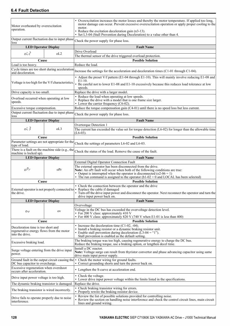
Motor overheated by overexcitationoperation.
• Overexcitation increases the motor losses and thereby the motor temperature. If applied too long,motor damage can occur. Prevent excessive overexcitation operation or apply proper cooling to themotor.
• Reduce the excitation deceleration gain (n3-13).• Set L3-04 (Stall Prevention during Deceleration) to a value other than 4.
Output current fluctuation due to input phaseloss Check the power supply for phase loss.
LED Operator Display Fault Name
oL2 Drive OverloadThe thermal sensor of the drive triggered overload protection.
Cause Possible SolutionLoad is too heavy. Reduce the load.Cycle times are too short during accelerationand deceleration. Increase the settings for the acceleration and deceleration times (C1-01 through C1-04).
Voltage is too high for the V/f characteristics.• Adjust the preset V/f pattern (E1-04 through E1-10). This will mainly involve reducing E1-08 and
E1-10.• Be careful not to lower E1-08 and E1-10 excessively because this reduces load tolerance at low
speeds.Drive capacity is too small. Replace the drive with a larger model.
Overload occurred when operating at lowspeeds.
• Reduce the load when operating at low speeds.• Replace the drive with a model that is one frame size larger.• Lower the carrier frequency (C6-02).
Excessive torque compensation. Reduce the torque compensation gain (C4-01) until there is no speed loss but less current.Output current fluctuation due to input phaseloss Check the power supply for phase loss.
LED Operator Display Fault Name
oL3Overtorque Detection 1The current has exceeded the value set for torque detection (L6-02) for longer than the allowable time(L6-03).
Cause Possible SolutionParameter settings are not appropriate for thetype of load. Check the settings of parameters L6-02 and L6-03.
There is a fault on the machine side (e.g., themachine is locked up). Check the status of the load. Remove the cause of the fault.
LED Operator Display Fault Name
oPr
External Digital Operator Connection FaultThe external operator has been disconnected from the drive.Note: An oPr fault will occur when both of the following conditions are true:• Output is interrupted when the operator is disconnected (o2-06 = 1)• The run command is assigned to the operator (b1-02 = 0 and LOCAL has been selected)
Cause Possible Solution
External operator is not properly connected tothe drive.
• Check the connection between the operator and the drive• Replace the cable if damaged• Turn off the drive input power and disconnect the operator. Next reconnect the operator and turn the
drive input power back on.LED Operator Display Fault Name
ovOvervoltageVoltage in the DC bus has exceeded the overvoltage detection level.• For 200 V class: approximately 410 V• For 400 V class: approximately 820 V (740 V when E1-01 is less than 400)
Cause Possible Solution
Deceleration time is too short andregenerative energy flows from the motorinto the drive.
• Increase the deceleration time (C1-02, -04).• Install a braking resistor or a dynamic braking resistor unit.• Enable stall prevention during deceleration (L3-04 = “1”).
Stall prevention is enabled as the default setting.
Excessive braking load. The braking torque was too high, causing regenerative energy to charge the DC bus.Reduce the braking torque, use a braking option, or lengthen decel time.
Surge voltage entering from the drive inputpower.
Install a DC reactor.Note: Voltage surge can result from thyristor convertor and phase advancing capacitor using samedrive main input power supply.
Ground fault in the output circuit causing theDC bus capacitor to overcharge.
• Check the motor wiring for ground faults.• Correct grounding shorts and turn the power back on.
Excessive regeneration when overshootoccurs after acceleration. • Lengthen the S-curve at acceleration end.
Drive input power voltage is too high. • Check the voltage.• Lower drive input power voltage within the limits listed in the specifications.
The dynamic braking transistor is damaged. Replace the drive.
The braking transistor is wired incorrectly. • Check braking transistor wiring for errors.• Properly rewire the braking resistor device.
Drive fails to operate properly due to noiseinterference.
• Review the list of possible solutions provided for controlling noise.• Review the section on handling noise interference and check the control circuit lines, main circuit
lines and ground wiring.
6.4 Fault Detection
128 YASKAWA ELECTRIC SIEP C710606 32A YASKAWA AC Drive – J1000 Technical Manual
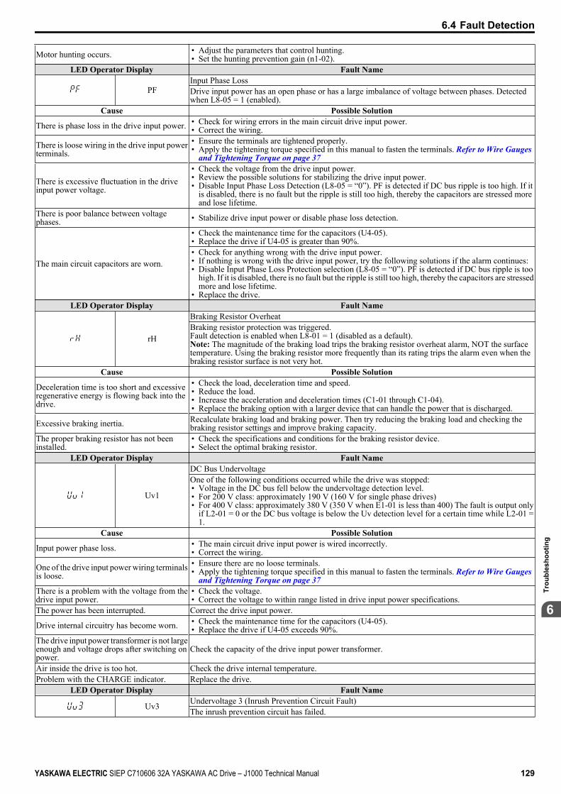
Motor hunting occurs. • Adjust the parameters that control hunting.• Set the hunting prevention gain (n1-02).
LED Operator Display Fault Name
PFInput Phase LossDrive input power has an open phase or has a large imbalance of voltage between phases. Detectedwhen L8-05 = 1 (enabled).
Cause Possible Solution
There is phase loss in the drive input power. • Check for wiring errors in the main circuit drive input power.• Correct the wiring.
There is loose wiring in the drive input powerterminals.
• Ensure the terminals are tightened properly.• Apply the tightening torque specified in this manual to fasten the terminals. Refer to Wire Gauges
and Tightening Torque on page 37
There is excessive fluctuation in the driveinput power voltage.
• Check the voltage from the drive input power.• Review the possible solutions for stabilizing the drive input power.• Disable Input Phase Loss Detection (L8-05 = “0”). PF is detected if DC bus ripple is too high. If it
is disabled, there is no fault but the ripple is still too high, thereby the capacitors are stressed moreand lose lifetime.
There is poor balance between voltagephases. • Stabilize drive input power or disable phase loss detection.
The main circuit capacitors are worn.
• Check the maintenance time for the capacitors (U4-05).• Replace the drive if U4-05 is greater than 90%.• Check for anything wrong with the drive input power.• If nothing is wrong with the drive input power, try the following solutions if the alarm continues:• Disable Input Phase Loss Protection selection (L8-05 = “0”). PF is detected if DC bus ripple is too
high. If it is disabled, there is no fault but the ripple is still too high, thereby the capacitors are stressedmore and lose lifetime.
• Replace the drive.LED Operator Display Fault Name
rH
Braking Resistor OverheatBraking resistor protection was triggered.Fault detection is enabled when L8-01 = 1 (disabled as a default).Note: The magnitude of the braking load trips the braking resistor overheat alarm, NOT the surfacetemperature. Using the braking resistor more frequently than its rating trips the alarm even when thebraking resistor surface is not very hot.
Cause Possible Solution
Deceleration time is too short and excessiveregenerative energy is flowing back into thedrive.
• Check the load, deceleration time and speed.• Reduce the load.• Increase the acceleration and deceleration times (C1-01 through C1-04).• Replace the braking option with a larger device that can handle the power that is discharged.
Excessive braking inertia. Recalculate braking load and braking power. Then try reducing the braking load and checking thebraking resistor settings and improve braking capacity.
The proper braking resistor has not beeninstalled.
• Check the specifications and conditions for the braking resistor device.• Select the optimal braking resistor.
LED Operator Display Fault Name
Uv1
DC Bus UndervoltageOne of the following conditions occurred while the drive was stopped:• Voltage in the DC bus fell below the undervoltage detection level.• For 200 V class: approximately 190 V (160 V for single phase drives)• For 400 V class: approximately 380 V (350 V when E1-01 is less than 400) The fault is output only
if L2-01 = 0 or the DC bus voltage is below the Uv detection level for a certain time while L2-01 =1.
Cause Possible Solution
Input power phase loss. • The main circuit drive input power is wired incorrectly.• Correct the wiring.
One of the drive input power wiring terminalsis loose.
• Ensure there are no loose terminals.• Apply the tightening torque specified in this manual to fasten the terminals. Refer to Wire Gauges
and Tightening Torque on page 37There is a problem with the voltage from thedrive input power.
• Check the voltage.• Correct the voltage to within range listed in drive input power specifications.
The power has been interrupted. Correct the drive input power.
Drive internal circuitry has become worn. • Check the maintenance time for the capacitors (U4-05).• Replace the drive if U4-05 exceeds 90%.
The drive input power transformer is not largeenough and voltage drops after switching onpower.
Check the capacity of the drive input power transformer.
Air inside the drive is too hot. Check the drive internal temperature.Problem with the CHARGE indicator. Replace the drive.
LED Operator Display Fault Name
Uv3 Undervoltage 3 (Inrush Prevention Circuit Fault)The inrush prevention circuit has failed.
6.4 Fault Detection
YASKAWA ELECTRIC SIEP C710606 32A YASKAWA AC Drive – J1000 Technical Manual 129
6
Trou
bles
hoot
ing
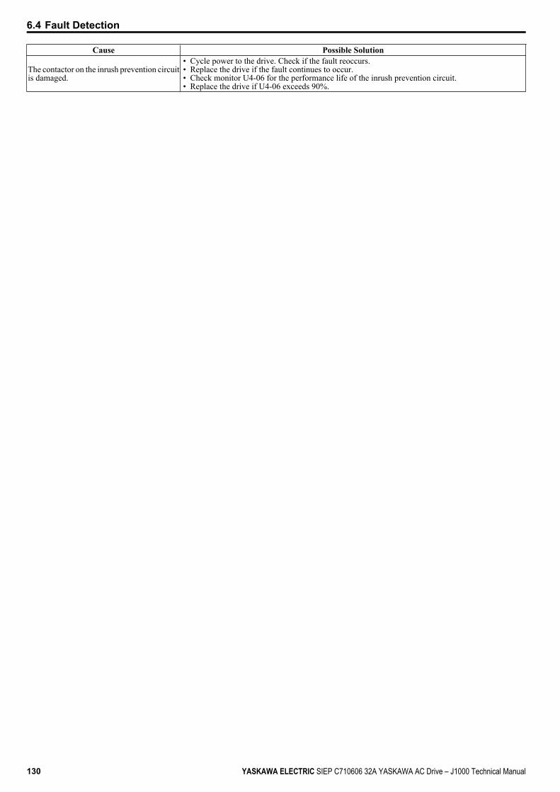
Cause Possible Solution
The contactor on the inrush prevention circuitis damaged.
• Cycle power to the drive. Check if the fault reoccurs.• Replace the drive if the fault continues to occur.• Check monitor U4-06 for the performance life of the inrush prevention circuit.• Replace the drive if U4-06 exceeds 90%.
6.4 Fault Detection
130 YASKAWA ELECTRIC SIEP C710606 32A YASKAWA AC Drive – J1000 Technical Manual

6.5 Alarm DetectionAlarms are drive protection functions that do not operate the fault contact. The drive will return to original status whenthe cause of the alarm has been removed.During an alarm condition, the Digital Operator display flashes and an alarm output is generated at the multi-functionoutput (H2-01), if programmed.Investigate the cause of the alarm and refer to Table 6.8 for the appropriate action.
u Alarm Codes, Causes, and Possible SolutionsTable 6.8 Alarm Codes, Causes, and Possible Solutions
LED Operator Display Minor Fault Name
bb BaseblockDrive output interrupted as indicated by an external baseblock signal.
Cause Possible Solutions Minor Fault(H2-01 = 10)
External baseblock signal entered viamulti-function input terminal (S1 to S5). Check external sequence and baseblock signal input timing. No output
LED Operator Display Minor Fault Name
CALL Serial Communication Transmission ErrorCommunication has not yet been established.
Cause Possible Solutions Minor Fault(H2-01 = 10)
Communications wiring is faulty, there isa short circuit, or something is notconnected properly.
• Check for wiring errors.• Correct the wiring.• Remove and ground shorts and reconnect loose wires.
YES
Programming error on the master side. Check communications at start-up and correct programming errors. YES
Communications circuitry is damaged. • Perform a self-diagnostics check.• Replace the drive if the fault continues to occurs. YES
Terminal resistance setting is incorrect. The terminal slave drive must have the internal terminal resistance switch set correctly.Place DIP switch S2 to the ON position. YES
LED Operator Display Minor Fault Name
CE MEMOBUS/Modbus Communication ErrorControl data was not received correctly for two seconds.
Cause Possible Solutions Minor Fault(H2-01 = 10)
A data error occurred due to noise.
• Check options available to minimize the effects of noise.• Counteract noise in the control circuit wiring, main circuit lines and ground wiring.• Reduce noise on the controller side.• Use surge absorbers on magnetic contactors or other equipment causing the
disturbance.• Use cables recommended by Yaskawa or another type of shielded line. The shield
should be grounded on the controller side or on the drive input power side.• Separate all wiring for communications devices from drive input power lines. Install
a noise filter to the input side of the drive input power.
YES
Communication protocol is incompatible. • Check the H5 parameter settings as well as the protocol setting in the controller.• Ensure settings are compatible. YES
The communication cycle is longer than 2seconds.
• Check the PLC.• Change the software settings in the PLC. YES
Incompatible PLC software settings orthere is a hardware problem.
• Check the PLC.• Remove the cause of the error on the controller side. YES
Communications cable is disconnected ordamaged.
• Check the connector for a signal through the cable.• Replace the communications cable. YES
LED Operator Display Minor Fault NameCrST Can Not Reset
Cause Possible SolutionsMinor Fault
Output(H2-01 = 10)
Fault reset was being executed when a runcommand was entered.
• Ensure that a run command cannot be entered from the external terminals or optionunit during fault reset.
• Turn off the run command.YES
LED Operator Display Minor Fault Name
EF Forward/Reverse Run Command Input ErrorBoth forward run and reverse run closed simultaneously for over 0.5 s.
Cause Possible SolutionsMinor Fault
Output(H2-01 = 10)
Sequence error Check the forward and reverse command sequence and correct the problem.Note: When minor fault EF detected, motor ramps to stop. YES
6.5 Alarm Detection
YASKAWA ELECTRIC SIEP C710606 32A YASKAWA AC Drive – J1000 Technical Manual 131
6
Trou
bles
hoot
ing
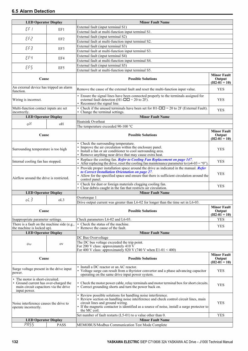
LED Operator Display Minor Fault Name
EF1 External fault (input terminal S1)External fault at multi-function input terminal S1.
EF2 External fault (input terminal S2)External fault at multi-function input terminal S2.
EF3 External fault (input terminal S3)External fault at multi-function input terminal S3.
EF4 External fault (input terminal S4)External fault at multi-function input terminal S4.
EF5 External fault (input terminal S5)External fault at multi-function input terminal S5.
Cause Possible SolutionsMinor Fault
Output(H2-01 = 10)
An external device has tripped an alarmfunction. Remove the cause of the external fault and reset the multi-function input value. YES
Wiring is incorrect.• Ensure the signal lines have been connected properly to the terminals assigned for
external fault detection (H1-oo = 20 to 2F).• Reconnect the signal line.
YES
Multi-function contact inputs are setincorrectly.
• Check if the unused terminals have been set for H1-oo = 20 to 2F (External Fault).• Change the terminal settings. YES
LED Operator Display Minor Fault Name
oH Heatsink OverheatThe temperature exceeded 90-100 °C
Cause Possible SolutionsMinor Fault
Output(H2-01 = 10)
Surrounding temperature is too high• Check the surrounding temperature.• Improve the air circulation within the enclosure panel.• Install a fan or air conditioner to cool surrounding area.• Remove anything near drive that may cause extra heat.
YES
Internal cooling fan has stopped. • Replace the cooling fan. Refer to Cooling Fan Replacement on page 147.• After replacing the drive, reset the cooling fan maintenance parameter to (o4-03 = “0”). YES
Airflow around the drive is restricted.
• Provide proper installation space around the drive as indicated in the manual. Refer to Correct Installation Orientation on page 27.
• Allow for the specified space and ensure that there is sufficient circulation around thecontrol panel.
YES
• Check for dust or foreign materials clogging cooling fan.• Clear debris caught in the fan that restricts air circulation. YES
LED Operator Display Minor Fault Name
oL3 Overtorque 1Drive output current was greater than L6-02 for longer than the time set in L6-03.
Cause Possible SolutionsMinor Fault
Output(H2-01 = 10)
Inappropriate parameter settings. Check parameters L6-02 and L6-03. YESThere is a fault on the machine side (e.g.,the machine is locked up).
• Check the status of the machine.• Remove the cause of the fault. YES
LED Operator Display Minor Fault Name
ovDC Bus OvervoltageThe DC bus voltage exceeded the trip point.For 200 V class: approximately 410 VFor 400 V class: approximately 820 V (740 V when E1-01 < 400)
Cause Possible SolutionsMinor Fault
Output(H2-01 = 10)
Surge voltage present in the drive inputpower.
• Install a DC reactor or an AC reactor.• Voltage surge can result from a thyristor convertor and a phase advancing capacitor
operating on the same drive input power system.YES
• The motor is short-circuited.• Ground current has over-charged the
main circuit capacitors via the driveinput power.
• Check the motor power cable, relay terminals and motor terminal box for short circuits.• Correct grounding shorts and turn the power back on. YES
Noise interference causes the drive tooperate incorrectly.
• Review possible solutions for handling noise interference.• Review section on handling noise interference and check control circuit lines, main
circuit lines and ground wiring.• If the magnetic contactor is identified as a source of noise, install a surge protector to
the MC coil.
YES
Set number of fault restarts (L5-01) to a value other than 0. YESLED Operator Display Minor Fault Name
PASS MEMOBUS/Modbus Communication Test Mode Complete
6.5 Alarm Detection
132 YASKAWA ELECTRIC SIEP C710606 32A YASKAWA AC Drive – J1000 Technical Manual
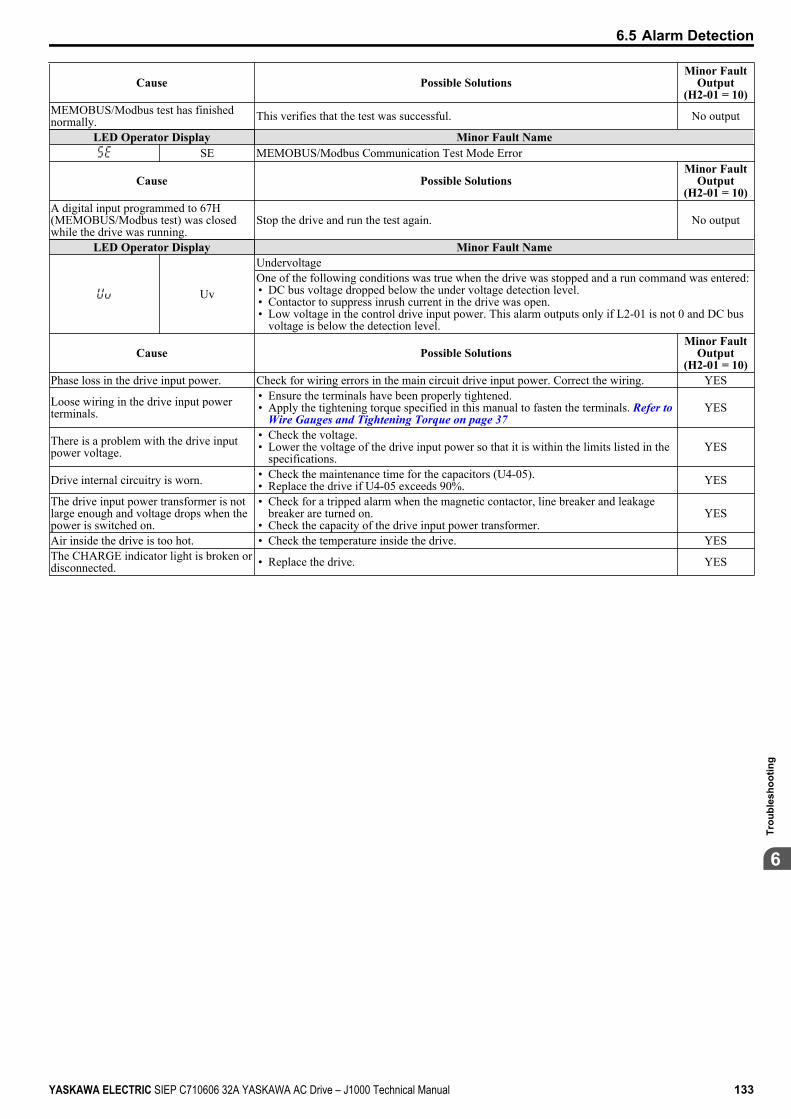
Cause Possible SolutionsMinor Fault
Output(H2-01 = 10)
MEMOBUS/Modbus test has finishednormally. This verifies that the test was successful. No output
LED Operator Display Minor Fault NameSE MEMOBUS/Modbus Communication Test Mode Error
Cause Possible SolutionsMinor Fault
Output(H2-01 = 10)
A digital input programmed to 67H(MEMOBUS/Modbus test) was closedwhile the drive was running.
Stop the drive and run the test again. No output
LED Operator Display Minor Fault Name
Uv
UndervoltageOne of the following conditions was true when the drive was stopped and a run command was entered:• DC bus voltage dropped below the under voltage detection level.• Contactor to suppress inrush current in the drive was open.• Low voltage in the control drive input power. This alarm outputs only if L2-01 is not 0 and DC bus
voltage is below the detection level.
Cause Possible SolutionsMinor Fault
Output(H2-01 = 10)
Phase loss in the drive input power. Check for wiring errors in the main circuit drive input power. Correct the wiring. YES
Loose wiring in the drive input powerterminals.
• Ensure the terminals have been properly tightened.• Apply the tightening torque specified in this manual to fasten the terminals. Refer to
Wire Gauges and Tightening Torque on page 37YES
There is a problem with the drive inputpower voltage.
• Check the voltage.• Lower the voltage of the drive input power so that it is within the limits listed in the
specifications.YES
Drive internal circuitry is worn. • Check the maintenance time for the capacitors (U4-05).• Replace the drive if U4-05 exceeds 90%. YES
The drive input power transformer is notlarge enough and voltage drops when thepower is switched on.
• Check for a tripped alarm when the magnetic contactor, line breaker and leakagebreaker are turned on.
• Check the capacity of the drive input power transformer.YES
Air inside the drive is too hot. • Check the temperature inside the drive. YESThe CHARGE indicator light is broken ordisconnected. • Replace the drive. YES
6.5 Alarm Detection
YASKAWA ELECTRIC SIEP C710606 32A YASKAWA AC Drive – J1000 Technical Manual 133
6
Trou
bles
hoot
ing
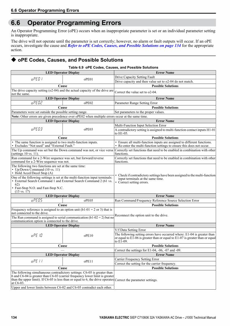
6.6 Operator Programming ErrorsAn Operator Programming Error (oPE) occurs when an inappropriate parameter is set or an individual parameter settingis inappropriate.The drive will not operate until the parameter is set correctly; however, no alarm or fault outputs will occur. If an oPEoccurs, investigate the cause and Refer to oPE Codes, Causes, and Possible Solutions on page 134 for the appropriateaction.
u oPE Codes, Causes, and Possible SolutionsTable 6.9 oPE Codes, Causes, and Possible Solutions
LED Operator Display Error Name
oPE01 Drive Capacity Setting FaultDrive capacity and then value set to o2-04 do not match.
Cause Possible SolutionsThe drive capacity setting (o2-04) and the actual capacity of the drive arenot the same. Correct the value set to o2-04.
LED Operator Display Error NameoPE02 Parameter Range Setting Error
Cause Possible SolutionsParameters were set outside the possible setting range. Set parameters to the proper values.Note: Other errors are given precedence over oPE02 when multiple errors occur at the same time.
LED Operator Display Error Name
oPE03Multi-Function Input Selection ErrorA contradictory setting is assigned to multi-function contact inputs H1-01to H1-05.
Cause Possible Solutions• The same function is assigned to two multi-function inputs.• Excludes “Not used” and “External Fault.”
• Ensure all multi-function inputs are assigned to different functions.• Re-enter the multi-function settings to ensure this does not occur.
The Up command was set but the Down command was not, or vice versa(settings 10 vs. 11).
Correctly set functions that need to be enabled in combination with otherfunctions.
Run command for a 2-Wire sequence was set, but forward/reversecommand for a 2-Wire sequence was not.
Correctly set functions that need to be enabled in combination with otherfunctions.
The following two functions are set at the same time:• Up/Down Command (10 vs. 11)• Hold Accel/Decel Stop (A) • Check if contradictory settings have been assigned to the multi-function
input terminals at the same time.• Correct setting errors.
One of the following settings is set at the multi-function input terminals:• External Search Command 1 and External Search Command 2 (61 vs.
62)• Fast-Stop N.O. and Fast-Stop N.C.
(15 vs. 17)LED Operator Display Error Name
oPE05 Run Command/Frequency Reference Source Selection ErrorCause Possible Solutions
Frequency reference is assigned to an option unit (b1-01 = 2 or 3) that isnot connected to the drive. Reconnect the option unit to the drive.The Run command is assigned to serial communication (b1-02 = 2) but nocommunication option is connected to the drive.
LED Operator Display Error Name
oPE10V/f Data Setting ErrorThe following setting errors have occurred where: E1-04 is greater thanor equal to E1-06 is greater than or equal to E1-07 is greater than or equalto E1-09.
Cause Possible Solutions— Correct the settings for E1-04, -06, -07 and -09.
LED Operator Display Error Name
oPE11 Carrier Frequency Setting ErrorCorrect the setting for the carrier frequency.
Cause Possible SolutionsThe following simultaneous contradictory settings: C6-05 is greater than6 and C6-04 is greater than C6-03 (carrier frequency lower limit is greaterthan the upper limit). If C6-05 is less than or equal to 6, the drive operatesat C6-03.
Correct the parameter settings.
Upper and lower limits between C6-02 and C6-05 contradict each other.
6.6 Operator Programming Errors
134 YASKAWA ELECTRIC SIEP C710606 32A YASKAWA AC Drive – J1000 Technical Manual
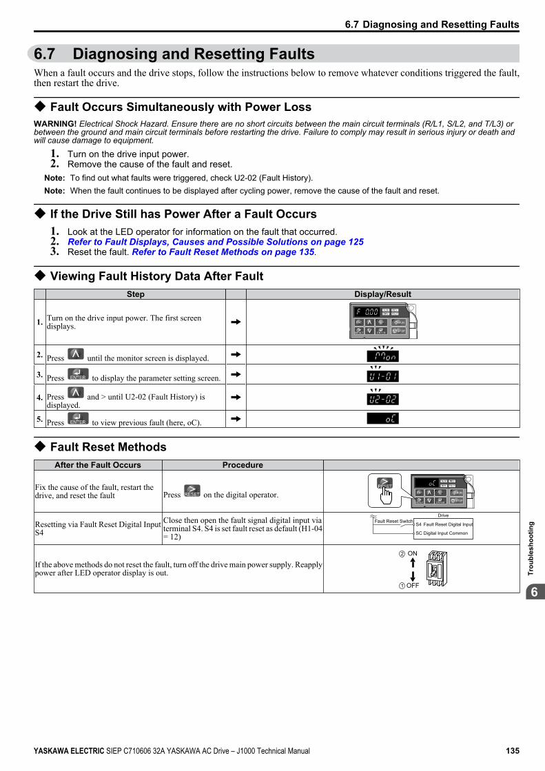
6.7 Diagnosing and Resetting FaultsWhen a fault occurs and the drive stops, follow the instructions below to remove whatever conditions triggered the fault,then restart the drive.
u Fault Occurs Simultaneously with Power LossWARNING! Electrical Shock Hazard. Ensure there are no short circuits between the main circuit terminals (R/L1, S/L2, and T/L3) orbetween the ground and main circuit terminals before restarting the drive. Failure to comply may result in serious injury or death andwill cause damage to equipment.
1. Turn on the drive input power.2. Remove the cause of the fault and reset.
Note: To find out what faults were triggered, check U2-02 (Fault History).Note: When the fault continues to be displayed after cycling power, remove the cause of the fault and reset.
u If the Drive Still has Power After a Fault Occurs1. Look at the LED operator for information on the fault that occurred.2. Refer to Fault Displays, Causes and Possible Solutions on page 1253. Reset the fault. Refer to Fault Reset Methods on page 135.
u Viewing Fault History Data After Fault Step Display/Result
1. Turn on the drive input power. The first screendisplays.
STOP
2. Press until the monitor screen is displayed.
3. Press to display the parameter setting screen.
4. Press and > until U2-02 (Fault History) isdisplayed.
5. Press to view previous fault (here, oC).
u Fault Reset MethodsAfter the Fault Occurs Procedure
Fix the cause of the fault, restart thedrive, and reset the fault Press on the digital operator.
STOP
Resetting via Fault Reset Digital InputS4
Close then open the fault signal digital input viaterminal S4. S4 is set fault reset as default (H1-04= 12)
Fault Reset SwitchDrive
S4 Fault Reset Digital Input
SC Digital Input Common
If the above methods do not reset the fault, turn off the drive main power supply. Reapplypower after LED operator display is out.
ON
OFF
2
1
6.7 Diagnosing and Resetting Faults
YASKAWA ELECTRIC SIEP C710606 32A YASKAWA AC Drive – J1000 Technical Manual 135
6
Trou
bles
hoot
ing

6.8 Troubleshooting without Fault DisplayThis section describes troubleshooting problems that do not trip an alarm or fault.
u Cannot Change Parameter SettingsCause Possible Solutions
The drive is running the motor (i.e., the Run commandis present).
• Stop the drive and switch over to the Programming Mode.• Most parameters cannot be edited during run.
The Access Level is set to restrict access to parametersettings. • Set the Access Level to allow parameters to be edited (A1-01 = 2).
The operator is not in the Parameter Setup Mode (theLED screen will display “PAr”).
• See what mode the LED parameter is current set for.• Parameters cannot be edited when in the Setup Mode (“STUP”). Switch modes so that “PAr”
appears on the screen.
The wrong password was entered.
• If the password entered to A1-04 does not match the password saved to A1-05, then drivesettings cannot be changed.
• Reset the password.If you cannot remember the password:•
Display parameter A1-04. Press the STOP button while pressing at the same time.Parameter A1-05 will appear.
• Set a new password to parameter A1-05.
Undervoltage was detected. • Check the drive input power voltage by looking at the DC bus voltage (U1-07).• Check all main circuit wiring.
u Motor Does Not Rotate Properly after Pressing RUN Button or after Entering ExternalRun Command
n Motor Does Not RotateCause Possible Solutions
The drive is not in the DriveMode.
• Check if the DRV light on the LED operator is lit.• Enter the Drive Mode to begin operating the motor. Refer to The Drive and Programming Modes on page 57.
The button was pushed.
Stop the drive and check if the correct frequency reference source is selected. If the operator keypad shall be thesource, the LO/RE button LED must be on, if the source is REMOTE, it must be off.Take the following step to solve the problem:•
Push the button.A Fast-Stop was executed andhas not yet been reset. Reset the Fast-Stop command.
Settings are incorrect for thesource that provides the runcommand.
Check parameter b1-02 (Run Command Selection).Set b1-02 so that it corresponds with the correct run command source.0: LED operator1: Control circuit terminal (default setting)2: MEMOBUS/Modbus communications
There is faulty wiring in thecontrol circuit terminals.
• Check the wiring for the control terminal.• Correct wiring mistakes.• Check the input terminal status monitor (U1-10).
The drive has been set to acceptthe frequency reference from theincorrect source.
Check parameter b1-01 (Frequency Reference Selection 1).Set b1-01 to the correct source of the frequency reference.0: LED operator1: Control circuit terminal (default setting)2: MEMOBUS/Modbus communications3: Potentiometer (option)
The terminal set to accept themain speed reference is set to theincorrect voltage and/or current.
Check DIP switch S1. Next assign the correct input level to terminal A1 (H3-01). Refer to DIP Switch S1 Analog Input Signal Selection on page 46.
Selection for the sink/sourcemode is incorrect. Check DIP switch S3. Refer to Sinking/Sourcing Mode Switch on page 44.
Frequency reference is too low. • Check the frequency reference monitor (U1-01).• Increase the frequency by changing the maximum output frequency (E1-09).
Multi-function analog input is setup to accept gain for thefrequency reference, but novoltage (current) has beenprovided.
• Check the multi-function analog input settings.• Check if H3-02 has been set to the proper values.• Check if the analog input value has been set properly.
The STOP button was pressedwhen the drive was started froma REMOTE source.
•When the STOP button is pressed, the drive will decelerate to stop.
• Switch off the run command and then re-enter a run command.•
The STOP button is disabled when o2-02 is set to 0.
Motor is not producing enoughtorque.
• Ensure the selected V/f pattern corresponds with the characteristics of the motor being used.• Increase both the minimum and mid output frequency voltages (E1-08, E1-10).Increase the frequency reference so that it is higher than the minimum frequency reference (E1-09).Increase the torque compensation gain (C4-01).
6.8 Troubleshooting without Fault Display
136 YASKAWA ELECTRIC SIEP C710606 32A YASKAWA AC Drive – J1000 Technical Manual
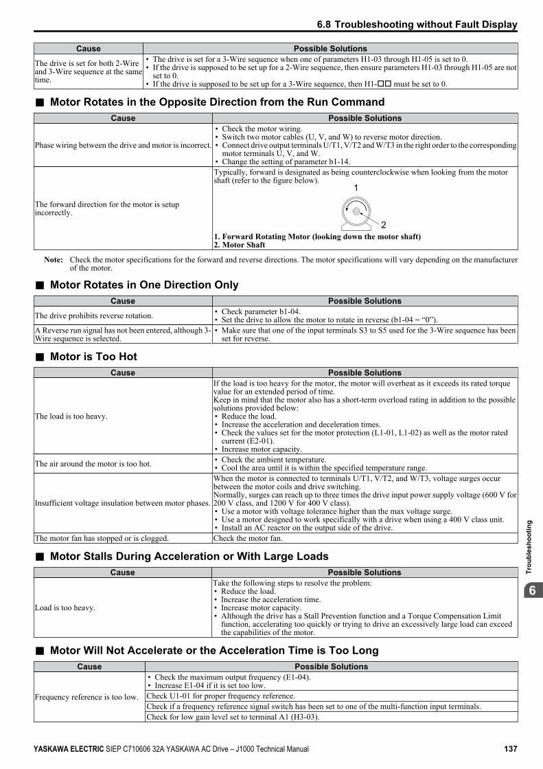
Cause Possible Solutions
The drive is set for both 2-Wireand 3-Wire sequence at the sametime.
• The drive is set for a 3-Wire sequence when one of parameters H1-03 through H1-05 is set to 0.• If the drive is supposed to be set up for a 2-Wire sequence, then ensure parameters H1-03 through H1-05 are not
set to 0.• If the drive is supposed to be set up for a 3-Wire sequence, then H1-oo must be set to 0.
n Motor Rotates in the Opposite Direction from the Run CommandCause Possible Solutions
Phase wiring between the drive and motor is incorrect.
• Check the motor wiring.• Switch two motor cables (U, V, and W) to reverse motor direction.• Connect drive output terminals U/T1, V/T2 and W/T3 in the right order to the corresponding
motor terminals U, V, and W.• Change the setting of parameter b1-14.
The forward direction for the motor is setupincorrectly.
Typically, forward is designated as being counterclockwise when looking from the motorshaft (refer to the figure below).
1
21. Forward Rotating Motor (looking down the motor shaft)2. Motor Shaft
Note: Check the motor specifications for the forward and reverse directions. The motor specifications will vary depending on the manufacturerof the motor.
n Motor Rotates in One Direction OnlyCause Possible Solutions
The drive prohibits reverse rotation. • Check parameter b1-04.• Set the drive to allow the motor to rotate in reverse (b1-04 = “0”).
A Reverse run signal has not been entered, although 3-Wire sequence is selected.
• Make sure that one of the input terminals S3 to S5 used for the 3-Wire sequence has beenset for reverse.
n Motor is Too HotCause Possible Solutions
The load is too heavy.
If the load is too heavy for the motor, the motor will overheat as it exceeds its rated torquevalue for an extended period of time.Keep in mind that the motor also has a short-term overload rating in addition to the possiblesolutions provided below:• Reduce the load.• Increase the acceleration and deceleration times.• Check the values set for the motor protection (L1-01, L1-02) as well as the motor rated
current (E2-01).• Increase motor capacity.
The air around the motor is too hot. • Check the ambient temperature.• Cool the area until it is within the specified temperature range.
Insufficient voltage insulation between motor phases.
When the motor is connected to terminals U/T1, V/T2, and W/T3, voltage surges occurbetween the motor coils and drive switching.Normally, surges can reach up to three times the drive input power supply voltage (600 V for200 V class, and 1200 V for 400 V class).• Use a motor with voltage tolerance higher than the max voltage surge.• Use a motor designed to work specifically with a drive when using a 400 V class unit.• Install an AC reactor on the output side of the drive.
The motor fan has stopped or is clogged. Check the motor fan.
n Motor Stalls During Acceleration or With Large LoadsCause Possible Solutions
Load is too heavy.
Take the following steps to resolve the problem:• Reduce the load.• Increase the acceleration time.• Increase motor capacity.• Although the drive has a Stall Prevention function and a Torque Compensation Limit
function, accelerating too quickly or trying to drive an excessively large load can exceedthe capabilities of the motor.
n Motor Will Not Accelerate or the Acceleration Time is Too LongCause Possible Solutions
Frequency reference is too low.
• Check the maximum output frequency (E1-04).• Increase E1-04 if it is set too low.Check U1-01 for proper frequency reference.Check if a frequency reference signal switch has been set to one of the multi-function input terminals.Check for low gain level set to terminal A1 (H3-03).
6.8 Troubleshooting without Fault Display
YASKAWA ELECTRIC SIEP C710606 32A YASKAWA AC Drive – J1000 Technical Manual 137
6
Trou
bles
hoot
ing
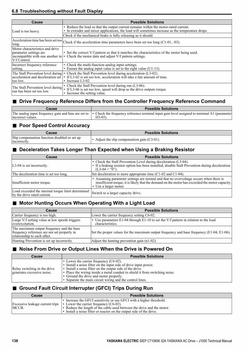
Cause Possible Solutions
Load is too heavy.• Reduce the load so that the output current remains within the motor-rated current.• In extruder and mixer applications, the load will sometimes increase as the temperature drops.Check if the mechanical brake is fully releasing as it should.
Acceleration time has been set toolong. Check if the acceleration time parameters have been set too long (C1-01, -03).
Motor characteristics and driveparameter settings areincompatible with one another inV/f Control.
• Set the correct V/f pattern so that it matches the characteristics of the motor being used.• Check the motor data and adjust V/f pattern settings.
Incorrect frequency referencesetting.
• Check the multi-function analog input settings.• Ensure the analog input value is set to the right value (U1-13).
The Stall Prevention level duringacceleration and deceleration settoo low.
• Check the Stall Prevention level during acceleration (L3-02).• If L3-02 is set too low, acceleration will take a fair amount of time.• Increase L3-02.
The Stall Prevention level duringrun has been set too low.
• Check the Stall Prevention level during run (L3-06).• If L3-06 is set too low, speed will drop as the drive outputs torque.• Increase the setting value.
n Drive Frequency Reference Differs from the Controller Frequency Reference CommandCause Possible Solutions
The analog input frequency gain and bias are set toincorrect values.
• Check the frequency reference terminal input gain level assigned to terminal A1 (parameterH3-03).
n Poor Speed Control AccuracyCause Possible Solutions
Slip compensation function disabled or set upincorrectly. • Adjust the slip compensation gain (C3-01).
n Deceleration Takes Longer Than Expected when Using a Braking ResistorCause Possible Solutions
L3-04 is set incorrectly.• Check the Stall Prevention Level during deceleration (L3-04).• If a braking resistor option has been installed, disable Stall Prevention during deceleration
(L3-04 = “0”).The deceleration time is set too long. Set deceleration to more appropriate time (C1-02 and C1-04).
Insufficient motor torque.• Assuming parameter settings are normal and that no overvoltage occurs when there is
insufficient torque, it is likely that the demand on the motor has exceeded the motor capacity.• Use a larger motor.
Load exceeded the internal torque limit determinedby the drive rated current. Switch to a larger capacity drive.
n Motor Hunting Occurs When Operating With a Light LoadCause Possible Solutions
Carrier frequency is too high. Lower the carrier frequency setting C6-02.Large V/f setting value at low speeds triggersoverexcitation.
• Use parameters E1-04 through E1-10 to set the V/f pattern in relation to the loadcharacteristics.
The maximum output frequency and the basefrequency reference are not set properly inrelationship to each other.
Set the proper values for the maximum output frequency and base frequency (E1-04, E1-06).
Hunting Prevention is set up incorrectly. Adjust the hunting prevention gain (n1-02).
n Noise From Drive or Output Lines When the Drive is Powered OnCause Possible Solutions
Relay switching in the drivegenerates excessive noise.
• Lower the carrier frequency (C6-02).• Install a noise filter on the input side of drive input power.• Install a noise filter on the output side of the drive.• Place the wiring inside a metal conduit to shield it from switching noise.• Ground the drive and motor properly.• Separate the main circuit wiring and the control lines.
n Ground Fault Circuit Interrupter (GFCI) Trips During RunCause Possible Solutions
Excessive leakage current tripsMCCB.
• Increase the GFCI sensitivity or use GFCI with a higher threshold.• Lower the carrier frequency (C6-02).• Reduce the length of the cable used between the drive and the motor.• Install a noise filter or reactor on the output side of the drive.
6.8 Troubleshooting without Fault Display
138 YASKAWA ELECTRIC SIEP C710606 32A YASKAWA AC Drive – J1000 Technical Manual
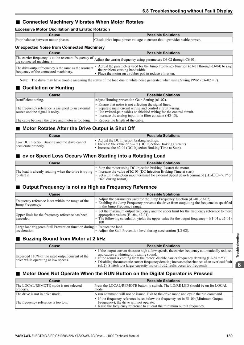
n Connected Machinery Vibrates When Motor RotatesExcessive Motor Oscillation and Erratic Rotation
Cause Possible SolutionsPoor balance between motor phases. Check drive input power voltage to ensure that it provides stable power.
Unexpected Noise from Connected MachineryCause Possible Solutions
The carrier frequency is at the resonant frequency ofthe connected machinery. Adjust the carrier frequency using parameters C6-02 through C6-05.
The drive output frequency is the same as the resonantfrequency of the connected machinery.
• Adjust the parameters used for the Jump Frequency function (d3-01 through d3-04) to skipthe problem-causing bandwidth.
• Place the motor on a rubber pad to reduce vibration.
Note: The drive may have trouble assessing the status of the load due to white noise generated when using Swing PWM (C6-02 = 7).
n Oscillation or HuntingCause Possible Solutions
Insufficient tuning. Adjust Hunting prevention Gain Setting (n1-02).
The frequency reference is assigned to an externalsource and the signal is noisy.
• Ensure that noise is not affecting the signal lines.• Separate main circuit wiring and control circuit wiring.• Use twisted-pair cables or shielded wiring for the control circuit.• Increase the analog input time filter constant (H3-13).
The cable between the drive and motor is too long. • Reduce the length of the cable.
n Motor Rotates After the Drive Output is Shut OffCause Possible Solutions
Low DC Injection Braking and the drive cannotdecelerate properly.
• Adjust the DC Injection braking settings.• Increase the value of b2-02 (DC Injection Braking Current).• Increase the b2-04 (DC Injection Braking Time at Stop).
n ov or Speed Loss Occurs When Starting into a Rotating LoadCause Possible Solutions
The load is already rotating when the drive is tryingto start it.
• Stop the motor using DC Injection braking. Restart the motor.• Increase the value of b2-03 (DC Injection Braking Time at start).• Set a multi-function input terminal for external Speed Search command (H1-oo=“61” or
“62” during restart).
n Output Frequency is not as High as Frequency ReferenceCause Possible Solutions
Frequency reference is set within the range of theJump Frequency.
• Adjust the parameters used for the Jump Frequency function (d3-01, d3-02).• Enabling the Jump Frequency prevents the drive from outputting the frequencies specified
in the Jump Frequency range.
Upper limit for the frequency reference has beenexceeded.
• Set the maximum output frequency and the upper limit for the frequency reference to moreappropriate values (E1-04, d2-01).
• The following calculation yields the upper value for the output frequency = E1-04 x d2-01 /100
Large load triggered Stall Prevention function duringacceleration.
• Reduce the load.• Adjust the Stall Prevention level during acceleration (L3-02).
n Buzzing Sound from Motor at 2 kHzCause Possible Solutions
Exceeded 110% of the rated output current of thedrive while operating at low speeds.
• If the output current rises too high at low speeds, the carrier frequency automatically reducesand causes a whining or buzzing sound.
• If the sound is coming from the motor, disable carrier frequency derating (L8-38 = “0”).• Disabling the automatic carrier frequency derating increases the chances of an overload fault
(oL2). Switch to a larger capacity motor if oL2 faults occur too frequently.
n Motor Does Not Operate When the RUN Button on the Digital Operator is PressedCause Possible Solutions
The LOCAL/REMOTE mode is not selectedproperly.
Press the LOCAL/REMOTE button to switch. The LO/RE LED should be on for LOCALmode.
The drive is not in drive mode. A run command will not be issued. Exit to the drive mode and cycle the run command.
The frequency reference is too low.• If the frequency reference is set below the frequency set in E1-09 (Minimum Output
Frequency), the drive will not operate.• Raise the frequency reference to at least the minimum output frequency.
6.8 Troubleshooting without Fault Display
YASKAWA ELECTRIC SIEP C710606 32A YASKAWA AC Drive – J1000 Technical Manual 139
6
Trou
bles
hoot
ing
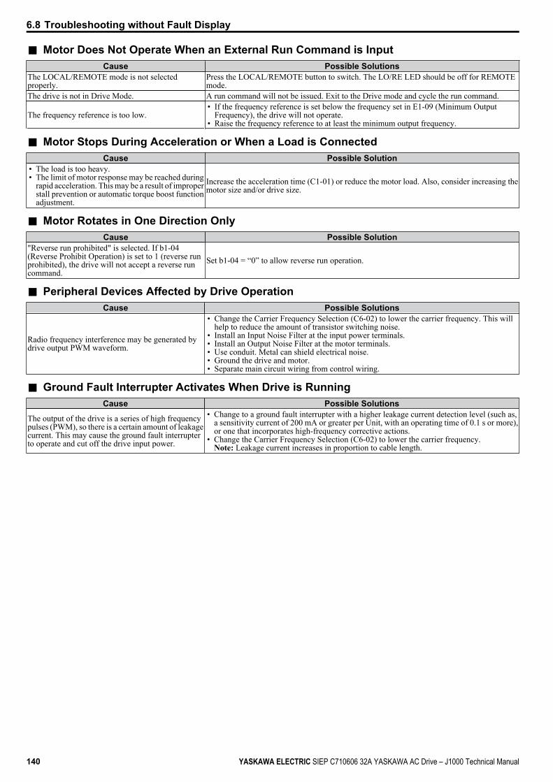
n Motor Does Not Operate When an External Run Command is InputCause Possible Solutions
The LOCAL/REMOTE mode is not selectedproperly.
Press the LOCAL/REMOTE button to switch. The LO/RE LED should be off for REMOTEmode.
The drive is not in Drive Mode. A run command will not be issued. Exit to the Drive mode and cycle the run command.
The frequency reference is too low.• If the frequency reference is set below the frequency set in E1-09 (Minimum Output
Frequency), the drive will not operate.• Raise the frequency reference to at least the minimum output frequency.
n Motor Stops During Acceleration or When a Load is ConnectedCause Possible Solution
• The load is too heavy.• The limit of motor response may be reached during
rapid acceleration. This may be a result of improperstall prevention or automatic torque boost functionadjustment.
Increase the acceleration time (C1-01) or reduce the motor load. Also, consider increasing themotor size and/or drive size.
n Motor Rotates in One Direction OnlyCause Possible Solution
"Reverse run prohibited" is selected. If b1-04(Reverse Prohibit Operation) is set to 1 (reverse runprohibited), the drive will not accept a reverse runcommand.
Set b1-04 = “0” to allow reverse run operation.
n Peripheral Devices Affected by Drive OperationCause Possible Solutions
Radio frequency interference may be generated bydrive output PWM waveform.
• Change the Carrier Frequency Selection (C6-02) to lower the carrier frequency. This willhelp to reduce the amount of transistor switching noise.
• Install an Input Noise Filter at the input power terminals.• Install an Output Noise Filter at the motor terminals.• Use conduit. Metal can shield electrical noise.• Ground the drive and motor.• Separate main circuit wiring from control wiring.
n Ground Fault Interrupter Activates When Drive is RunningCause Possible Solutions
The output of the drive is a series of high frequencypulses (PWM), so there is a certain amount of leakagecurrent. This may cause the ground fault interrupterto operate and cut off the drive input power.
• Change to a ground fault interrupter with a higher leakage current detection level (such as,a sensitivity current of 200 mA or greater per Unit, with an operating time of 0.1 s or more),or one that incorporates high-frequency corrective actions.
• Change the Carrier Frequency Selection (C6-02) to lower the carrier frequency.Note: Leakage current increases in proportion to cable length.
6.8 Troubleshooting without Fault Display
140 YASKAWA ELECTRIC SIEP C710606 32A YASKAWA AC Drive – J1000 Technical Manual
Periodic Inspection & MaintenanceThis chapter describes the periodic inspection and maintenance of the drive to ensure that it receivesthe proper care to maintain overall performance.
7.1 SECTION SAFETY..........................................................................................1427.2 INSPECTION...................................................................................................1447.3 PERIODIC MAINTENANCE............................................................................1467.4 DRIVE COOLING FANS.................................................................................147
7
YASKAWA ELECTRIC SIEP C710606 32A YASKAWA AC Drive – J1000 Technical Manual 141
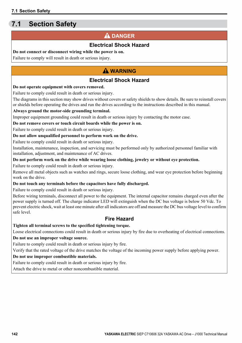
7.1 Section Safety DANGER
Electrical Shock HazardDo not connect or disconnect wiring while the power is on.Failure to comply will result in death or serious injury.
WARNINGElectrical Shock Hazard
Do not operate equipment with covers removed.Failure to comply could result in death or serious injury.The diagrams in this section may show drives without covers or safety shields to show details. Be sure to reinstall coversor shields before operating the drives and run the drives according to the instructions described in this manual.Always ground the motor-side grounding terminal.Improper equipment grounding could result in death or serious injury by contacting the motor case.Do not remove covers or touch circuit boards while the power is on.Failure to comply could result in death or serious injury.Do not allow unqualified personnel to perform work on the drive.Failure to comply could result in death or serious injury.Installation, maintenance, inspection, and servicing must be performed only by authorized personnel familiar withinstallation, adjustment, and maintenance of AC drives.Do not perform work on the drive while wearing loose clothing, jewelry or without eye protection.Failure to comply could result in death or serious injury.Remove all metal objects such as watches and rings, secure loose clothing, and wear eye protection before beginningwork on the drive.Do not touch any terminals before the capacitors have fully discharged.Failure to comply could result in death or serious injury.Before wiring terminals, disconnect all power to the equipment. The internal capacitor remains charged even after thepower supply is turned off. The charge indicator LED will extinguish when the DC bus voltage is below 50 Vdc. Toprevent electric shock, wait at least one minute after all indicators are off and measure the DC bus voltage level to confirmsafe level.
Fire HazardTighten all terminal screws to the specified tightening torque.Loose electrical connections could result in death or serious injury by fire due to overheating of electrical connections.Do not use an improper voltage source.Failure to comply could result in death or serious injury by fire.Verify that the rated voltage of the drive matches the voltage of the incoming power supply before applying power.Do not use improper combustible materials.Failure to comply could result in death or serious injury by fire.Attach the drive to metal or other noncombustible material.
7.1 Section Safety
142 YASKAWA ELECTRIC SIEP C710606 32A YASKAWA AC Drive – J1000 Technical Manual
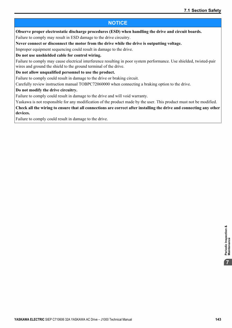
NOTICEObserve proper electrostatic discharge procedures (ESD) when handling the drive and circuit boards.Failure to comply may result in ESD damage to the drive circuitry.Never connect or disconnect the motor from the drive while the drive is outputting voltage.Improper equipment sequencing could result in damage to the drive.Do not use unshielded cable for control wiring.Failure to comply may cause electrical interference resulting in poor system performance. Use shielded, twisted-pairwires and ground the shield to the ground terminal of the drive.Do not allow unqualified personnel to use the product.Failure to comply could result in damage to the drive or braking circuit.Carefully review instruction manual TOBPC72060000 when connecting a braking option to the drive.Do not modify the drive circuitry.Failure to comply could result in damage to the drive and will void warranty.Yaskawa is not responsible for any modification of the product made by the user. This product must not be modified.Check all the wiring to ensure that all connections are correct after installing the drive and connecting any otherdevices.Failure to comply could result in damage to the drive.
7.1 Section Safety
YASKAWA ELECTRIC SIEP C710606 32A YASKAWA AC Drive – J1000 Technical Manual 143
7
Perio
dic
Insp
ectio
n &
Mai
nten
ance
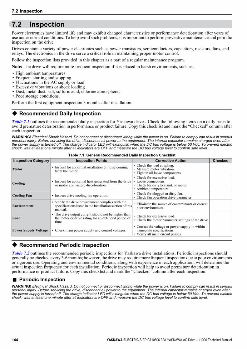
7.2 InspectionPower electronics have limited life and may exhibit changed characteristics or performance deterioration after years ofuse under normal conditions. To help avoid such problems, it is important to perform preventive maintenance and periodicinspection on the drive.Drives contain a variety of power electronics such as power transistors, semiconductors, capacitors, resistors, fans, andrelays. The electronics in the drive serve a critical role in maintaining proper motor control.Follow the inspection lists provided in this chapter as a part of a regular maintenance program.Note: The drive will require more frequent inspection if it is placed in harsh environments, such as:• High ambient temperatures• Frequent starting and stopping• Fluctuations in the AC supply or load• Excessive vibrations or shock loading• Dust, metal dust, salt, sulfuric acid, chlorine atmospheres• Poor storage conditions.Perform the first equipment inspection 3 months after installation.
u Recommended Daily InspectionTable 7.1 outlines the recommended daily inspection for Yaskawa drives. Check the following items on a daily basis toavoid premature deterioration in performance or product failure. Copy this checklist and mark the “Checked” column aftereach inspection.WARNING! Electrical Shock Hazard. Do not connect or disconnect wiring while the power is on. Failure to comply can result in seriouspersonal injury. Before servicing the drive, disconnect all power to the equipment. The internal capacitor remains charged even afterthe power supply is turned off. The charge indicator LED will extinguish when the DC bus voltage is below 50 Vdc. To prevent electricshock, wait at least one minute after all indicators are OFF and measure the DC bus voltage level to confirm safe level.
Table 7.1 General Recommended Daily Inspection ChecklistInspection Category Inspection Points Corrective Action Checked
Motor • Inspect for abnormal oscillation or noise comingfrom the motor.
• Check the load coupling.• Measure motor vibration.• Tighten all loose components.
Cooling • Inspect for abnormal heat generated from the driveor motor and visible discoloration.
• Check for excessive load.• Loose connections• Check for dirty heatsink or motor.• Ambient temperature
Cooling Fan • Inspect drive cooling fan operation. • Check for clogged or dirty fan.• Check fan operation drive parameter.
Environment• Verify the drive environment complies with the
specifications listed in the Installation section of thismanual.
• Eliminate the source of contaminants or correctpoor environment.
Load• The drive output current should not be higher than
the motor or drive rating for an extended period oftime.
• Check for excessive load.• Check the motor parameter settings of the drive.
Power Supply Voltage • Check main power supply and control voltages.• Correct the voltage or power supply to within
nameplate specifications.• Verify all main circuit phases.
u Recommended Periodic InspectionTable 7.2 outlines the recommended periodic inspections for Yaskawa drive installations. Periodic inspections shouldgenerally be checked every 3-6 months; however, the drive may require more frequent inspection due to poor environmentsor rigorous use. Operating and environmental conditions, along with experience in each application, will determine theactual inspection frequency for each installation. Periodic inspection will help to avoid premature deterioration inperformance or product failure. Copy this checklist and mark the “Checked” column after each inspection.
n Periodic InspectionWARNING! Electrical Shock Hazard. Do not connect or disconnect wiring while the power is on. Failure to comply can result in seriouspersonal injury. Before servicing the drive, disconnect all power to the equipment. The internal capacitor remains charged even afterthe power supply is turned off. The charge indicator LED will extinguish when the DC bus voltage is below 50 Vdc. To prevent electricshock, wait at least one minute after all indicators are OFF and measure the DC bus voltage level to confirm safe level.
7.2 Inspection
144 YASKAWA ELECTRIC SIEP C710606 32A YASKAWA AC Drive – J1000 Technical Manual
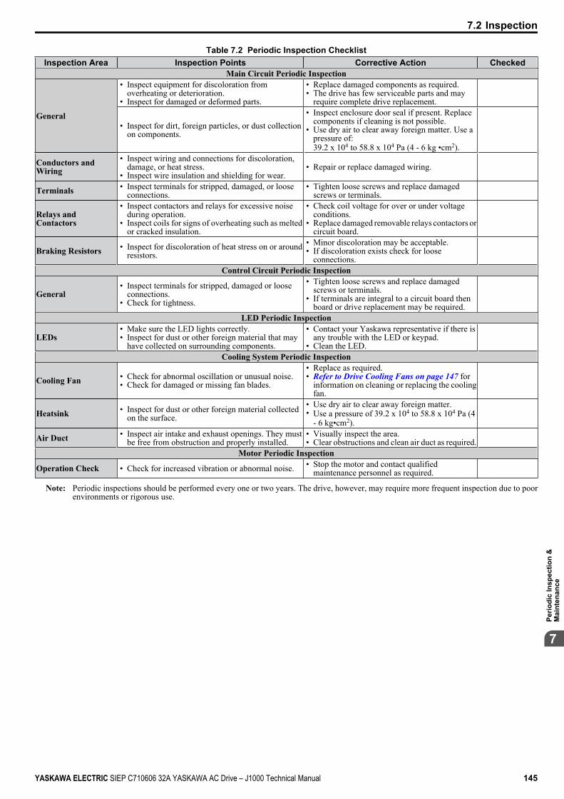
Table 7.2 Periodic Inspection ChecklistInspection Area Inspection Points Corrective Action Checked
Main Circuit Periodic Inspection
General
• Inspect equipment for discoloration fromoverheating or deterioration.
• Inspect for damaged or deformed parts.
• Replace damaged components as required.• The drive has few serviceable parts and may
require complete drive replacement.
• Inspect for dirt, foreign particles, or dust collectionon components.
• Inspect enclosure door seal if present. Replacecomponents if cleaning is not possible.
• Use dry air to clear away foreign matter. Use apressure of:39.2 x 10⁴ to 58.8 x 10⁴ Pa (4 - 6 kg •cm2).
Conductors andWiring
• Inspect wiring and connections for discoloration,damage, or heat stress.
• Inspect wire insulation and shielding for wear.• Repair or replace damaged wiring.
Terminals • Inspect terminals for stripped, damaged, or looseconnections.
• Tighten loose screws and replace damagedscrews or terminals.
Relays andContactors
• Inspect contactors and relays for excessive noiseduring operation.
• Inspect coils for signs of overheating such as meltedor cracked insulation.
• Check coil voltage for over or under voltageconditions.
• Replace damaged removable relays contactors orcircuit board.
Braking Resistors • Inspect for discoloration of heat stress on or aroundresistors.
• Minor discoloration may be acceptable.• If discoloration exists check for loose
connections.
Control Circuit Periodic Inspection
General• Inspect terminals for stripped, damaged or loose
connections.• Check for tightness.
• Tighten loose screws and replace damagedscrews or terminals.
• If terminals are integral to a circuit board thenboard or drive replacement may be required.
LED Periodic Inspection
LEDs• Make sure the LED lights correctly.• Inspect for dust or other foreign material that may
have collected on surrounding components.
• Contact your Yaskawa representative if there isany trouble with the LED or keypad.
• Clean the LED.
Cooling System Periodic Inspection
Cooling Fan • Check for abnormal oscillation or unusual noise.• Check for damaged or missing fan blades.
• Replace as required.• Refer to Drive Cooling Fans on page 147 for
information on cleaning or replacing the coolingfan.
Heatsink • Inspect for dust or other foreign material collectedon the surface.
• Use dry air to clear away foreign matter.• Use a pressure of 39.2 x 10⁴ to 58.8 x 10⁴ Pa (4
- 6 kg•cm2).
Air Duct • Inspect air intake and exhaust openings. They mustbe free from obstruction and properly installed.
• Visually inspect the area.• Clear obstructions and clean air duct as required.
Motor Periodic Inspection
Operation Check • Check for increased vibration or abnormal noise. • Stop the motor and contact qualifiedmaintenance personnel as required.
Note: Periodic inspections should be performed every one or two years. The drive, however, may require more frequent inspection due to poorenvironments or rigorous use.
7.2 Inspection
YASKAWA ELECTRIC SIEP C710606 32A YASKAWA AC Drive – J1000 Technical Manual 145
7
Perio
dic
Insp
ectio
n &
Mai
nten
ance
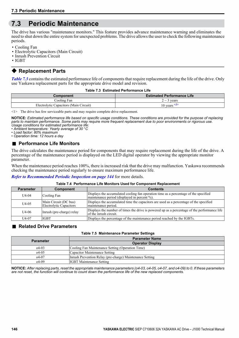
7.3 Periodic MaintenanceThe drive has various "maintenance monitors." This feature provides advance maintenance warning and eliminates theneed to shut down the entire system for unexpected problems. The drive allows the user to check the following maintenanceperiods.• Cooling Fan• Electrolytic Capacitors (Main Circuit)• Inrush Prevention Circuit• IGBT
u Replacement PartsTable 7.3 contains the estimated performance life of components that require replacement during the life of the drive. Onlyuse Yaskawa replacement parts for the appropriate drive model and revision.
Table 7.3 Estimated Performance LifeComponent Estimated Performance LifeCooling Fan 2 ~ 3 years
Electrolytic Capacitors (Main Circuit) 10 years <1>
<1> The drive has few serviceable parts and may require complete drive replacement.
NOTICE: Estimated performance life based on specific usage conditions. These conditions are provided for the purpose of replacingparts to maintain performance. Some parts may require more frequent replacement due to poor environments or rigorous use.Usage conditions for estimated performance life:• Ambient temperature: Yearly average of 30 °C• Load factor: 80% maximum• Operation time: 12 hours a day
n Performance Life MonitorsThe drive calculates the maintenance period for components that may require replacement during the life of the drive. Apercentage of the maintenance period is displayed on the LED digital operator by viewing the appropriate monitorparameter.When the maintenance period reaches 100%, there is increased risk that the drive may malfunction. Yaskawa recommendschecking the maintenance period regularly to ensure maximum performance life.Refer to Recommended Periodic Inspection on page 144 for more details.
Table 7.4 Performance Life Monitors Used for Component ReplacementParameter Component Contents
U4-04 Cooling Fan Displays the accumulated cooling fan operation time as a percentage of the specifiedmaintenance period (displayed in percent %).
U4-05 Main Circuit (DC bus)Electrolytic Capacitors
Displays the accumulated time the capacitors are used as a percentage of the specifiedmaintenance period.
U4-06 Inrush (pre-charge) relay Displays the number of times the drive is powered up as a percentage of the performance lifeof the inrush circuit.
U4-07 IGBT Displays the percentage of the maintenance period reached by the IGBTs.
n Related Drive ParametersTable 7.5 Maintenance Parameter Settings
Parameter Parameter NameOperator Display
o4-03 Cooling Fan Maintenance Setting (Operation Time)o4-05 Capacitor Maintenance Settingo4-07 Inrush Prevention Relay (pre-charge) Maintenance Settingo4-09 IGBT Maintenance Setting
NOTICE: After replacing parts, reset the appropriate maintenance parameters (o4-03, o4-05, o4-07, and o4-09) to 0. If these parametersare not reset, the function will continue to count down the performance life of the new replaced components.
7.3 Periodic Maintenance
146 YASKAWA ELECTRIC SIEP C710606 32A YASKAWA AC Drive – J1000 Technical Manual

7.4 Drive Cooling FansNOTICE: Follow cooling fan replacement instructions. The cooling fan cannot operate properly when installed incorrectly and couldseriously damage the drive. To ensure maximum useful product life, replace all cooling fans when performing maintenance.
Contact your Yaskawa representative or supplier to order replacement cooling fans as required.Some drive models have multiple cooling fans.For drives with multiple cooling fans, replace all the fans when performing maintenance to ensure maximum useful productlife.
u Cooling Fan ReplacementThe cooling fan is installed on the top of the drive. The cooling fan can easily be replaced without tools or removal of thedrive or enclosure parts.WARNING! Electrical Shock Hazard. Do not connect or disconnect wiring while the power is on. Failure to comply can result in seriouspersonal injury. Before servicing the drive, disconnect all power to the equipment. The internal capacitor remains charged even afterthe power supply is turned off. The charge indicator LED will extinguish when the DC bus voltage is below 50 Vdc. To prevent electricshock, wait at least one minute after all indicators are OFF and measure the DC bus voltage level to confirm safe level.CAUTION! Burn Hazard. Do not touch a hot drive heatsink. Failure to comply could result in minor or moderate injury. Shut off the powerto the drive when replacing the cooling fan. To prevent burns, wait at least 15 minutes and ensure the heatsink has cooled down.
n Removing the Cooling Fan1. Depress the right and left sides of the fan cover tabs and pull upward. Remove the fan cover from the top of the
drive. The following figure illustrates a drive with a single cooling fan.
A
B
C
A – Fan coverB – Cooling fan
C – Tab
Figure 7.1 Remove the Cooling Fan Cover
2. Remove the fan cable carefully, disconnect the pluggable connector and remove the fan.
7.4 Drive Cooling Fans
YASKAWA ELECTRIC SIEP C710606 32A YASKAWA AC Drive – J1000 Technical Manual 147
7
Perio
dic
Insp
ectio
n &
Mai
nten
ance
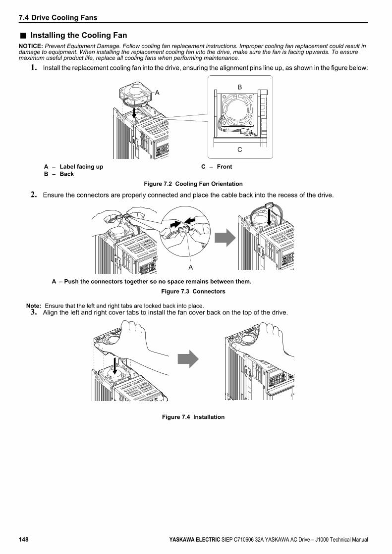
n Installing the Cooling FanNOTICE: Prevent Equipment Damage. Follow cooling fan replacement instructions. Improper cooling fan replacement could result indamage to equipment. When installing the replacement cooling fan into the drive, make sure the fan is facing upwards. To ensuremaximum useful product life, replace all cooling fans when performing maintenance.
1. Install the replacement cooling fan into the drive, ensuring the alignment pins line up, as shown in the figure below:
AB
C
A – Label facing upB – Back
C – Front
Figure 7.2 Cooling Fan Orientation
2. Ensure the connectors are properly connected and place the cable back into the recess of the drive.
A
A – Push the connectors together so no space remains between them.Figure 7.3 Connectors
Note: Ensure that the left and right tabs are locked back into place.3. Align the left and right cover tabs to install the fan cover back on the top of the drive.
Figure 7.4 Installation
7.4 Drive Cooling Fans
148 YASKAWA ELECTRIC SIEP C710606 32A YASKAWA AC Drive – J1000 Technical Manual
Peripheral Devices & OptionsThis chapter explains the installation of available peripheral devices and options for the drive.
8.1 SECTION SAFETY..........................................................................................1508.2 DRIVE OPTIONS AND PERIPHERAL DEVICES...........................................1528.3 CONNECTING PERIPHERAL DEVICES........................................................1538.4 INSTALLING PERIPHERAL DEVICES..........................................................1548.5 COMMUNICATION OPTIONS........................................................................161
8
YASKAWA ELECTRIC SIEP C710606 32A YASKAWA AC Drive – J1000 Technical Manual 149
8.1 Section Safety DANGER
Electrical Shock HazardDo not connect or disconnect wiring while the power is on.Failure to comply will result in death or serious injury.Disconnect all power to the drive, wait at least one minute after all indicators are off, measure the DC bus voltage toconfirm safe level, and check for unsafe voltages before servicing to prevent electric shock. The internal capacitor remainscharged even after the power supply is turned off. The charge indicator LED will extinguish when the DC bus voltageis below 50 Vdc.
WARNINGElectrical Shock Hazard
Do not operate equipment with covers removed.Failure to comply could result in death or serious injury.The diagrams in this section may show drives without covers or safety shields to show details. Be sure to reinstall coversor shields before operating the drives and run the drives according to the instructions described in this manual.Do not remove covers or touch circuit boards while the power is on.Failure to comply could result in death or serious injury.
WARNINGDo not touch any terminals before the capacitors have fully discharged.Failure to comply could result in death or serious injury.Before wiring terminals, disconnect all power to the equipment. The internal capacitor remains charged even after thepower supply is turned off. The charge indicator LED will extinguish when the DC bus voltage is below 50 Vdc. Toprevent electric shock, wait at least one minute after all indicators are off and measure the DC bus voltage level to confirmsafe level.Do not allow unqualified personnel to perform work on the drive.Failure to comply could result in death or serious injury.Installation, maintenance, inspection and servicing must be performed only by authorized personnel familiar withinstallation, adjustment and maintenance of AC drives.Do not perform work on the drive while wearing loose clothing, jewelry or without eye protection.Failure to comply could result in death or serious injury.Remove all metal objects such as watches and rings, secure loose clothing and wear eye protection before beginningwork on the drive.Always ground the motor-side grounding terminal.Improper equipment grounding could result in death or serious injury by contacting the motor case.
WARNINGDo not change wiring or remove option unit while power is running through the drive.Failure to comply could result in death or serious injury.Disconnect all power to the drive and check for unsafe voltages before servicing.Tighten all terminal screws to the specified tightening torque.Loose electrical connections could result in death or serious injury by fire due to overheating of electrical connections.
8.1 Section Safety
150 YASKAWA ELECTRIC SIEP C710606 32A YASKAWA AC Drive – J1000 Technical Manual

NOTICEObserve proper electrostatic discharge procedures (ESD) when handling the drive and circuit boards.Failure to comply may result in ESD damage to the drive circuitry.Never connect or disconnect the motor from the drive while the drive is outputting voltage.Improper equipment sequencing could result in damage to the drive.
8.1 Section Safety
YASKAWA ELECTRIC SIEP C710606 32A YASKAWA AC Drive – J1000 Technical Manual 151
8
Perip
hera
l Dev
ices
&O
ptio
ns

8.2 Drive Options and Peripheral DevicesThe following table of peripheral devices lists the names of the various devices/options available for Yaskawa drives.Contact Yaskawa or your Yaskawa agent to order these peripheral devices.• Peripheral Device Selection: Refer to Yaskawa catalog for selection and part numbers.• Peripheral Device Installation: Refer to option manual for option installation instructions.
Table 8.1 Available Peripheral DevicesOption Model Number Description
Power OptionsDC Reactor — DC reactor to improve power factorAC Reactor — AC reactor to improve power factorBraking Resistor ERF-150WJ Series 3% ED, 150 W braking resistor
Interface Options
Remote LED Operator JVOP-182 Remote operator with LED display and copy function;Cable length max. 3 m
USB/Copy Unit JVOP-181Allows the user to copy and verify parameter settingsbetween drives. Can also be used as adapter to connectthe drive to a PC USB portNote: SI-232/JC option is required
RS-232C Serial CommunicationInterface SI-232/JC RS232C communications interface to connect the drive
to a PC or the optional copy unit
Remote Operator Interface SI-232/J RS232C communications interface for usage with theexternal LED operator JVOP-182
Potentiometer Option AI-V3/J Potentiometer option for setting the frequency referencedirectly at the drive
Mechanical OptionsHeatsink External MountingAttachment EZZ020568 Installation kit for mounting the drive with the heatsink
outside of the panel (side-by-side mounting possible)DIN Rail Attachment EZZ08122 Installation kit for mounting the drive on a DIN rail
NEMA Type 1 Kit EZZ020564 Parts to make the drive conform to NEMA Type 1enclosure
OthersDrive Wizard Plus — PC tool for drive setup and parameter management
Communication OptionsRS-422/485 SerialCommunications Interface SI-485/J Interface for RS-422/485 communications using the
MEMOBUS/Modbus RTU protocol
8.2 Drive Options and Peripheral Devices
152 YASKAWA ELECTRIC SIEP C710606 32A YASKAWA AC Drive – J1000 Technical Manual
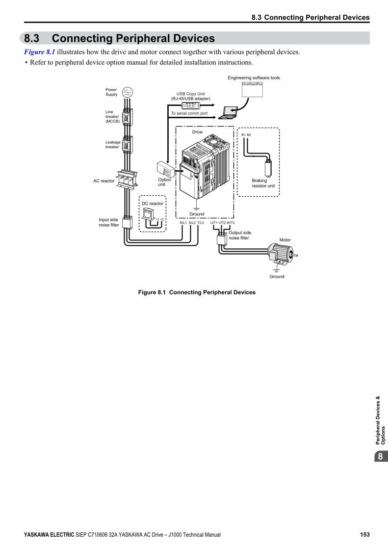
8.3 Connecting Peripheral DevicesFigure 8.1 illustrates how the drive and motor connect together with various peripheral devices.• Refer to peripheral device option manual for detailed installation instructions.
AC reactor
Input sidenoise filter
DC reactor
Optionunit
U/T1 V/T2 W/T3R/L1 S/L2+2+1
T/L3
Ground
Output sidenoise filter
Ground
Motor
B1 B2
DriveWizardPlus
Drive
Brakingresistor unit
Engineering software tools
USB Copy Unit(RJ-45/USB adapter)
To serial comm port
CopyVerify Read LO
CK
YAS
KAW
AJV
OP
-181
US
B C
opy
Uni
t
CO
ME
RR
PowerSupply
Linebreaker(MCCB)
Leakagebreaker
Figure 8.1 Connecting Peripheral Devices
8.3 Connecting Peripheral Devices
YASKAWA ELECTRIC SIEP C710606 32A YASKAWA AC Drive – J1000 Technical Manual 153
8
Perip
hera
l Dev
ices
&O
ptio
ns
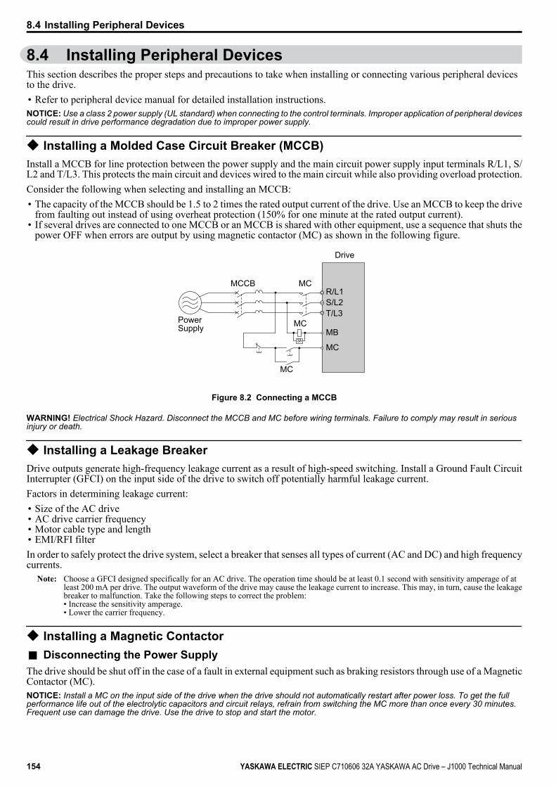
8.4 Installing Peripheral DevicesThis section describes the proper steps and precautions to take when installing or connecting various peripheral devicesto the drive.• Refer to peripheral device manual for detailed installation instructions.NOTICE: Use a class 2 power supply (UL standard) when connecting to the control terminals. Improper application of peripheral devicescould result in drive performance degradation due to improper power supply.
u Installing a Molded Case Circuit Breaker (MCCB)Install a MCCB for line protection between the power supply and the main circuit power supply input terminals R/L1, S/L2 and T/L3. This protects the main circuit and devices wired to the main circuit while also providing overload protection.Consider the following when selecting and installing an MCCB:• The capacity of the MCCB should be 1.5 to 2 times the rated output current of the drive. Use an MCCB to keep the drive
from faulting out instead of using overheat protection (150% for one minute at the rated output current).• If several drives are connected to one MCCB or an MCCB is shared with other equipment, use a sequence that shuts the
power OFF when errors are output by using magnetic contactor (MC) as shown in the following figure.
Drive
PowerSupply
R/L1
MB
MCCB MC
MC
MC
MC
S/L2T/L3
SA
Figure 8.2 Connecting a MCCB
WARNING! Electrical Shock Hazard. Disconnect the MCCB and MC before wiring terminals. Failure to comply may result in seriousinjury or death.
u Installing a Leakage BreakerDrive outputs generate high-frequency leakage current as a result of high-speed switching. Install a Ground Fault CircuitInterrupter (GFCI) on the input side of the drive to switch off potentially harmful leakage current.Factors in determining leakage current:• Size of the AC drive• AC drive carrier frequency• Motor cable type and length• EMI/RFI filterIn order to safely protect the drive system, select a breaker that senses all types of current (AC and DC) and high frequencycurrents.
Note: Choose a GFCI designed specifically for an AC drive. The operation time should be at least 0.1 second with sensitivity amperage of atleast 200 mA per drive. The output waveform of the drive may cause the leakage current to increase. This may, in turn, cause the leakagebreaker to malfunction. Take the following steps to correct the problem:• Increase the sensitivity amperage.• Lower the carrier frequency.
u Installing a Magnetic Contactorn Disconnecting the Power SupplyThe drive should be shut off in the case of a fault in external equipment such as braking resistors through use of a MagneticContactor (MC).NOTICE: Install a MC on the input side of the drive when the drive should not automatically restart after power loss. To get the fullperformance life out of the electrolytic capacitors and circuit relays, refrain from switching the MC more than once every 30 minutes.Frequent use can damage the drive. Use the drive to stop and start the motor.
8.4 Installing Peripheral Devices
154 YASKAWA ELECTRIC SIEP C710606 32A YASKAWA AC Drive – J1000 Technical Manual
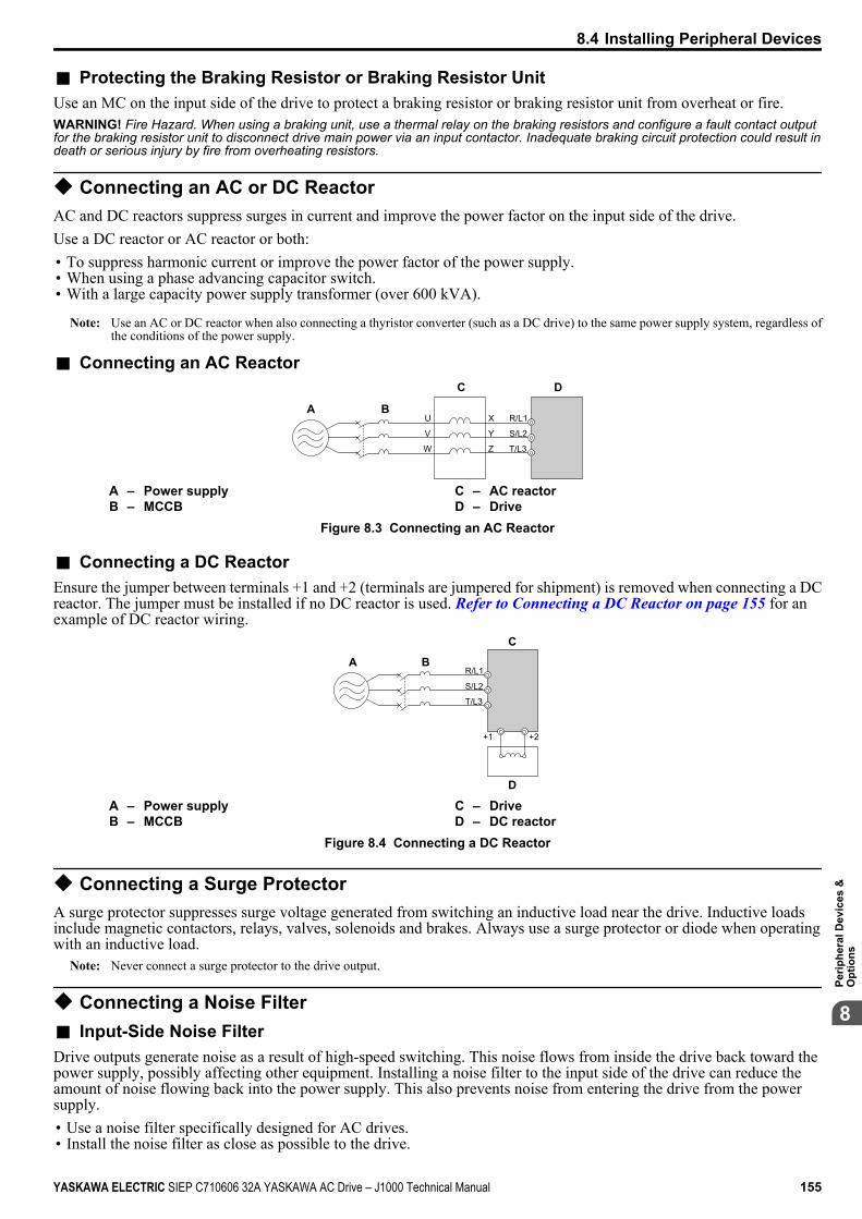
n Protecting the Braking Resistor or Braking Resistor UnitUse an MC on the input side of the drive to protect a braking resistor or braking resistor unit from overheat or fire.WARNING! Fire Hazard. When using a braking unit, use a thermal relay on the braking resistors and configure a fault contact outputfor the braking resistor unit to disconnect drive main power via an input contactor. Inadequate braking circuit protection could result indeath or serious injury by fire from overheating resistors.
u Connecting an AC or DC ReactorAC and DC reactors suppress surges in current and improve the power factor on the input side of the drive.Use a DC reactor or AC reactor or both:• To suppress harmonic current or improve the power factor of the power supply.• When using a phase advancing capacitor switch.• With a large capacity power supply transformer (over 600 kVA).
Note: Use an AC or DC reactor when also connecting a thyristor converter (such as a DC drive) to the same power supply system, regardless ofthe conditions of the power supply.
n Connecting an AC Reactor
BA
C D
R/L1U
V
W
X
Y
Z
S/L2
T/L3
A – Power supplyB – MCCB
C – AC reactorD – Drive
Figure 8.3 Connecting an AC Reactor
n Connecting a DC ReactorEnsure the jumper between terminals +1 and +2 (terminals are jumpered for shipment) is removed when connecting a DCreactor. The jumper must be installed if no DC reactor is used. Refer to Connecting a DC Reactor on page 155 for anexample of DC reactor wiring.
A
C
D
R/L1
+1 +2
B
S/L2
T/L3
A – Power supplyB – MCCB
C – DriveD – DC reactor
Figure 8.4 Connecting a DC Reactor
u Connecting a Surge ProtectorA surge protector suppresses surge voltage generated from switching an inductive load near the drive. Inductive loadsinclude magnetic contactors, relays, valves, solenoids and brakes. Always use a surge protector or diode when operatingwith an inductive load.
Note: Never connect a surge protector to the drive output.
u Connecting a Noise Filtern Input-Side Noise FilterDrive outputs generate noise as a result of high-speed switching. This noise flows from inside the drive back toward thepower supply, possibly affecting other equipment. Installing a noise filter to the input side of the drive can reduce theamount of noise flowing back into the power supply. This also prevents noise from entering the drive from the powersupply.• Use a noise filter specifically designed for AC drives.• Install the noise filter as close as possible to the drive.
8.4 Installing Peripheral Devices
YASKAWA ELECTRIC SIEP C710606 32A YASKAWA AC Drive – J1000 Technical Manual 155
8
Perip
hera
l Dev
ices
&O
ptio
ns
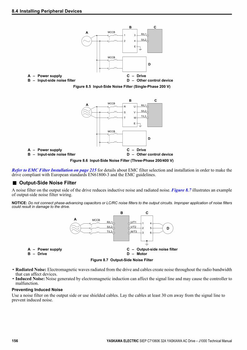
B C
D
A R/L11
2
3
4
E
MCCB
MCCB
S/L2
A – Power supplyB – Input-side noise filter
C – DriveD – Other control device
Figure 8.5 Input-Side Noise Filter (Single-Phase 200 V)
C
D
AB
R/L1U
V
W
R
S
T
E
MCCB
MCCB
S/L2
T/L3
A – Power supplyB – Input-side noise filter
C – DriveD – Other control device
Figure 8.6 Input-Side Noise Filter (Three-Phase 200/400 V)
Refer to EMC Filter Installation on page 215 for details about EMC filter selection and installation in order to make thedrive compliant with European standards EN61800-3 and the EMC guidelines.
n Output-Side Noise FilterA noise filter on the output side of the drive reduces inductive noise and radiated noise. Figure 8.7 illustrates an exampleof output-side noise filter wiring.
NOTICE: Do not connect phase-advancing capacitors or LC/RC noise filters to the output circuits. Improper application of noise filterscould result in damage to the drive.
CB
A
D
R/L1MCCB
S/L2
T/L3
U/T1
V/T2
W/T3
1
2
3
4
5
6
A – Power supplyB – Drive
C – Output-side noise filterD – Motor
Figure 8.7 Output-Side Noise Filter
• Radiated Noise: Electromagnetic waves radiated from the drive and cables create noise throughout the radio bandwidththat can affect devices.
• Induced Noise: Noise generated by electromagnetic induction can affect the signal line and may cause the controller tomalfunction.
Preventing Induced NoiseUse a noise filter on the output side or use shielded cables. Lay the cables at least 30 cm away from the signal line toprevent induced noise.
8.4 Installing Peripheral Devices
156 YASKAWA ELECTRIC SIEP C710606 32A YASKAWA AC Drive – J1000 Technical Manual

B
A C
F
G
D
E
R/L1MCCB
S/L2T/L3
U/T1V/T2W/T3
A – Power supplyB – DriveC – Shielded motor cableD – Motor
E – Separate at least 30 cmF – ControllerG – Signal line
Figure 8.8 Preventing Induced Noise
Reducing Radiated/Radio Frequency NoiseThe drive, input lines, and output lines generate radio frequency noise. Use noise filters on input and output sides andinstall the drive in a metal enclosure panel to reduce radio frequency noise.
Note: The cable running between the drive and motor should be as short as possible.
C EDB F
A
R/L1MCCB
S/L2T/L3
U/T1V/T2W/T3
G
A – Metal enclosureB – Power supplyC – Noise filterD – Drive
E – Noise filterF – Shielded motor cableG – Motor
Figure 8.9 Reducing Radio Frequency Noise
u Installing Fuses on the Input SideAlways install input fuses. Refer to Standards Compliance on page 211 for details on input fuse selection.
u Installing a Motor Thermal Overload (oL) Relay on the Drive OutputMotor thermal overload relays protect the motor by disconnecting power lines to the motor due to a motor overloadcondition.Install a motor thermal overload relay between the drive and motor:• When operating multiple motors on a single AC drive.• When using a power line bypass to operate the motor directly from the power line.It is not necessary to install a motor thermal overload relay when operating a single motor from a single AC drive. TheAC drive has UL recognized electronic motor overload protection built into the drive software.
Note: Disable the motor protection function (L1-0 1 = “0”) when using an external motor thermal overload relay. The relay should shut off mainpower on the input side of the main circuit when triggered.
n General Precautions when Using Thermal Overload RelaysThe following application precautions should be considered when using motor thermal overload relays on the output ofAC drives in order to prevent nuisance trips or overheat of the motor at low speeds:• Low speed motor operation• Use of multiple motors on a single AC drive• Motor cable length• Nuisance tripping resulting from high AC drive carrier frequency
8.4 Installing Peripheral Devices
YASKAWA ELECTRIC SIEP C710606 32A YASKAWA AC Drive – J1000 Technical Manual 157
8
Perip
hera
l Dev
ices
&O
ptio
ns

Low Speed Operation and Motor Thermal oL RelaysGenerally, thermal relays are applied on general-purpose motors. When general-purpose motors are driven by AC drives,the motor current is approximately 5 ~ 10% greater than if driven by the commercial power supply. In addition, the coolingcapacity of a motor with a shaft-driven fan decreases when operating at low speeds. Even if the load current is within themotor rated value, motor overheating may occur. A thermal relay cannot effectively protect the motor due to the reductionof cooling at low speeds. For this reason, apply the UL recognized electronic thermal overload protection function builtinto the drive whenever possible.UL recognized electronic thermal overload function of the drive: Speed-dependent heat characteristics are simulatedusing data from standard motors and force-ventilated motors. The motor is protected from overload using this function.
Using One Drive with Multiple MotorsTurn off the electronic thermal overload function. Please refer to the appropriate product instruction manual to determinewhich parameter disables this function.The UL recognized electronic thermal overload function of the drive cannot be applied when using multiple motors onone drive.
Long Motor CablesWhen long motor cables and high carrier frequency are used, nuisance tripping of the thermal relay may occur due toincreased leakage current. Therefore, reduce the carrier frequency or increase the tripping level of the thermal overloadrelay.
Nuisance Tripping Resulting from High AC Drive Carrier FrequencyCurrent waveforms generated by high carrier frequency PWM drives tend to create additional temperature rise in overloadrelays. Therefore, it may be necessary to increase the trip level setting when encountering nuisance triggering of the relay.WARNING! Fire Hazard. Confirm an actual motor overload condition is not present prior to increasing the thermal oL trip setting. Checklocal electrical codes before making adjustments to motor thermal overload settings.
u NEMA Type 1 KitWARNING! Fire Hazard. Provide sufficient cooling when installing the drive inside an enclosed panel or cabinet. Failure to comply couldresult in overheating and fire. When multiple drives are placed inside the same enclosure panel, install proper cooling to ensure airentering the enclosure does not exceed 40 °C.
The optional NEMA Type 1 kit can be installed to raise the enclosure protection level of an IP20/Open-Chassis drive toNEMA Type 1. Drives with a NEMA Type 1 kit cannot be installed using side-by-side mounting unless the top cover isremoved. The drive does not retain NEMA Type 1 integrity with the top cover removed. Refer to Installation Orientation and Spacing on page 27 for installation instructions.
n Installation EnvironmentTable 8.2 Installation Environment
Environment Conditions
Ambient Temperature
-10 °C to +40 °C (NEMA Type 1/wall-mounted enclosure)Drive reliability improves in environments without wide temperature fluctuations.When using an enclosure panel, install a cooling fan or air conditioner in the area to ensure that the air temperatureinside the enclosure does not exceed the specified levels.Do not allow ice to develop on the drive.
Refer to Installation Environment on page 26 for all other installation environment specifications.
n Exterior and Mounting Dimensions for NEMA Type 1 KitThe following table matches each drive model with its appropriate drawing.
Table 8.3 Drive Models and Types
Protective DesignDrive Model CIMR-Jo
PageSingle-Phase200 V Class
Three-Phase200 V Class
Three-Phase400 V Class
NEMA Type 1
Bo0001FBo0002FBo0003F
2o0001F2o0002F2o0004F
– 159
Bo0006FBo0010F
2o0006F2o0010F2o0012F2o0020F
4o0001F4o0002F4o0004F4o0005F4o0007F4o0009F4o0011F
159
8.4 Installing Peripheral Devices
158 YASKAWA ELECTRIC SIEP C710606 32A YASKAWA AC Drive – J1000 Technical Manual
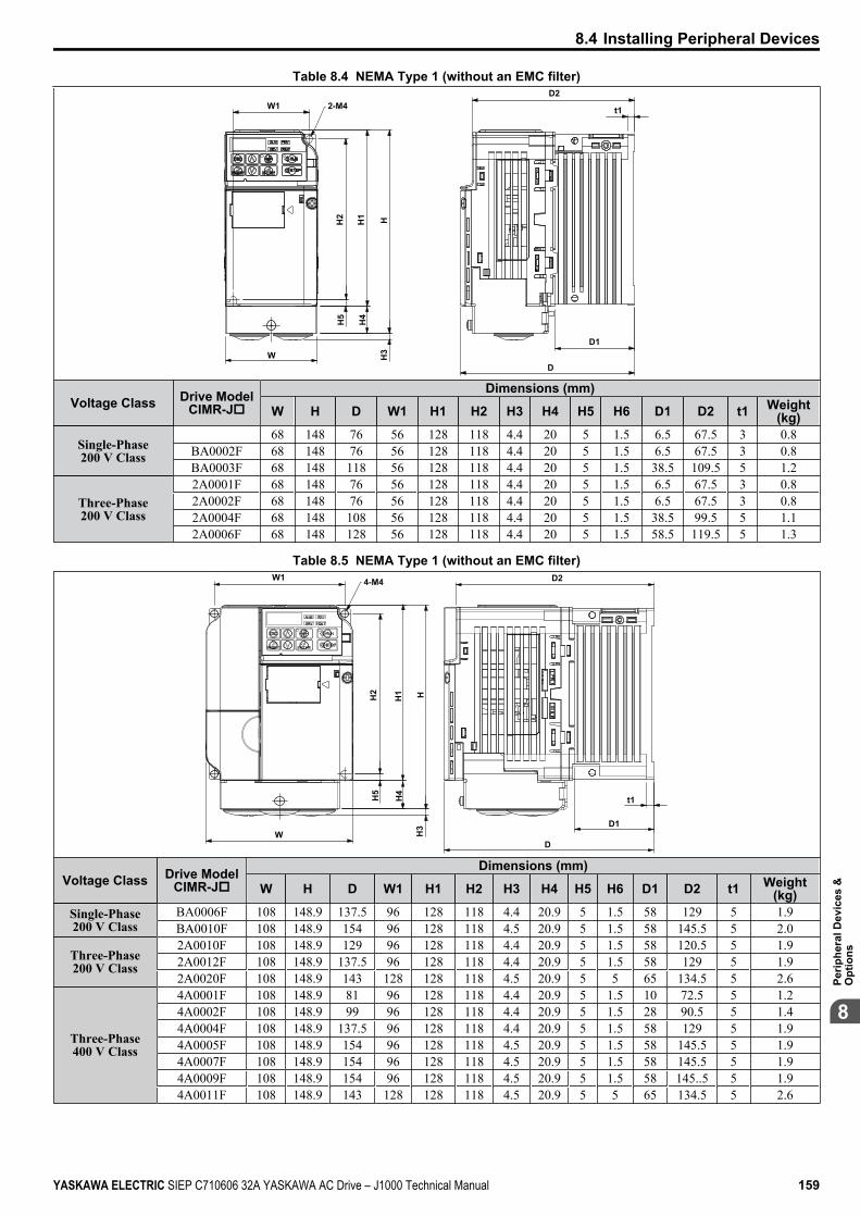
Table 8.4 NEMA Type 1 (without an EMC filter)
D1
t1
H1 HH2
H5
H4
H3W
D2
D
2-M4W1
Voltage Class Drive ModelCIMR-Jo
Dimensions (mm)
W H D W1 H1 H2 H3 H4 H5 H6 D1 D2 t1 Weight(kg)
Single-Phase200 V Class
68 148 76 56 128 118 4.4 20 5 1.5 6.5 67.5 3 0.8BA0002F 68 148 76 56 128 118 4.4 20 5 1.5 6.5 67.5 3 0.8BA0003F 68 148 118 56 128 118 4.4 20 5 1.5 38.5 109.5 5 1.2
Three-Phase200 V Class
2A0001F 68 148 76 56 128 118 4.4 20 5 1.5 6.5 67.5 3 0.82A0002F 68 148 76 56 128 118 4.4 20 5 1.5 6.5 67.5 3 0.82A0004F 68 148 108 56 128 118 4.4 20 5 1.5 38.5 99.5 5 1.12A0006F 68 148 128 56 128 118 4.4 20 5 1.5 58.5 119.5 5 1.3
Table 8.5 NEMA Type 1 (without an EMC filter)4-M4W1
W
H5
H2
H4
HH
3
H1
D1
D2
D
t1
Voltage Class Drive ModelCIMR-Jo
Dimensions (mm)
W H D W1 H1 H2 H3 H4 H5 H6 D1 D2 t1 Weight(kg)
Single-Phase200 V Class
BA0006F 108 148.9 137.5 96 128 118 4.4 20.9 5 1.5 58 129 5 1.9BA0010F 108 148.9 154 96 128 118 4.5 20.9 5 1.5 58 145.5 5 2.0
Three-Phase200 V Class
2A0010F 108 148.9 129 96 128 118 4.4 20.9 5 1.5 58 120.5 5 1.92A0012F 108 148.9 137.5 96 128 118 4.4 20.9 5 1.5 58 129 5 1.92A0020F 108 148.9 143 128 128 118 4.5 20.9 5 5 65 134.5 5 2.6
Three-Phase400 V Class
4A0001F 108 148.9 81 96 128 118 4.4 20.9 5 1.5 10 72.5 5 1.24A0002F 108 148.9 99 96 128 118 4.4 20.9 5 1.5 28 90.5 5 1.44A0004F 108 148.9 137.5 96 128 118 4.4 20.9 5 1.5 58 129 5 1.94A0005F 108 148.9 154 96 128 118 4.5 20.9 5 1.5 58 145.5 5 1.94A0007F 108 148.9 154 96 128 118 4.5 20.9 5 1.5 58 145.5 5 1.94A0009F 108 148.9 154 96 128 118 4.5 20.9 5 1.5 58 145..5 5 1.94A0011F 108 148.9 143 128 128 118 4.5 20.9 5 5 65 134.5 5 2.6
8.4 Installing Peripheral Devices
YASKAWA ELECTRIC SIEP C710606 32A YASKAWA AC Drive – J1000 Technical Manual 159
8
Perip
hera
l Dev
ices
&O
ptio
ns

n Removing the Protective Covers on a NEMA Type 1 Design1. Loosen the screw on the front cover to remove the front cover.
Figure 8.10 Remove the Front Cover on a NEMA Type 1 Drive
2. Loosen the screw on the terminal cover (Figure 8.11, B) to remove the terminal cover and expose the conduitbracket (Figure 8.11, A).
A
B
Figure 8.11 Remove the Terminal Cover on a NEMA Type 1 Drive
3. Loosen two screws attaching the conduit bracket (Figure 8.12, A) to remove.
A
Figure 8.12 Remove the Conduit Bracket on a NEMA Type 1 Drive
n Reattaching the Protective CoversPass power wiring and control signal wiring through the exit holes on the bottom of the conduit bracket of the drive. Placepower wiring and control signal wiring in separate conduits. Properly connect all wiring after installing the drive andconnecting other devices. Reattach all protective covers when wiring is complete.
A
A – Pass power wiring and control signal wiring through different exit holes at the bottom of the drive.Figure 8.13 Reattach the Protective Covers and Conduit Bracket on a NEMA Type 1 Drive
8.4 Installing Peripheral Devices
160 YASKAWA ELECTRIC SIEP C710606 32A YASKAWA AC Drive – J1000 Technical Manual
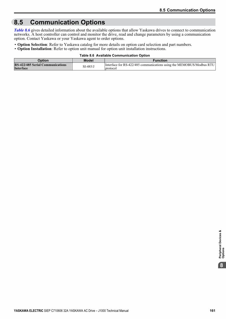
8.5 Communication OptionsTable 8.6 gives detailed information about the available options that allow Yaskawa drives to connect to communicationnetworks. A host controller can control and monitor the drive, read and change parameters by using a communicationoption. Contact Yaskawa or your Yaskawa agent to order options.• Option Selection: Refer to Yaskawa catalog for more details on option card selection and part numbers.• Option Installation: Refer to option unit manual for option unit installation instructions.
Table 8.6 Available Communication OptionOption Model Function
RS-422/485 Serial CommunicationsInterface SI-485/J Interface for RS-422/485 communications using the MEMOBUS/Modbus RTU
protocol
8.5 Communication Options
YASKAWA ELECTRIC SIEP C710606 32A YASKAWA AC Drive – J1000 Technical Manual 161
8
Perip
hera
l Dev
ices
&O
ptio
ns
8.5 Communication Options
This Page Intentionally Blank
162 YASKAWA ELECTRIC SIEP C710606 32A YASKAWA AC Drive – J1000 Technical Manual

Specifications
A.1 HEAVY DUTY AND NORMAL DUTY RATINGS............................................164A.2 SINGLE/THREE-PHASE 200 V CLASS DRIVE.............................................165A.3 THREE-PHASE 400 V CLASS DRIVES.........................................................166A.4 DRIVE SPECIFICATIONS...............................................................................167A.5 DRIVE WATT LOSS DATA.............................................................................169A.6 DRIVE DERATING DATA...............................................................................170
Appendix: A
YASKAWA ELECTRIC SIEP C710606 32A YASKAWA AC Drive – J1000 Technical Manual 163
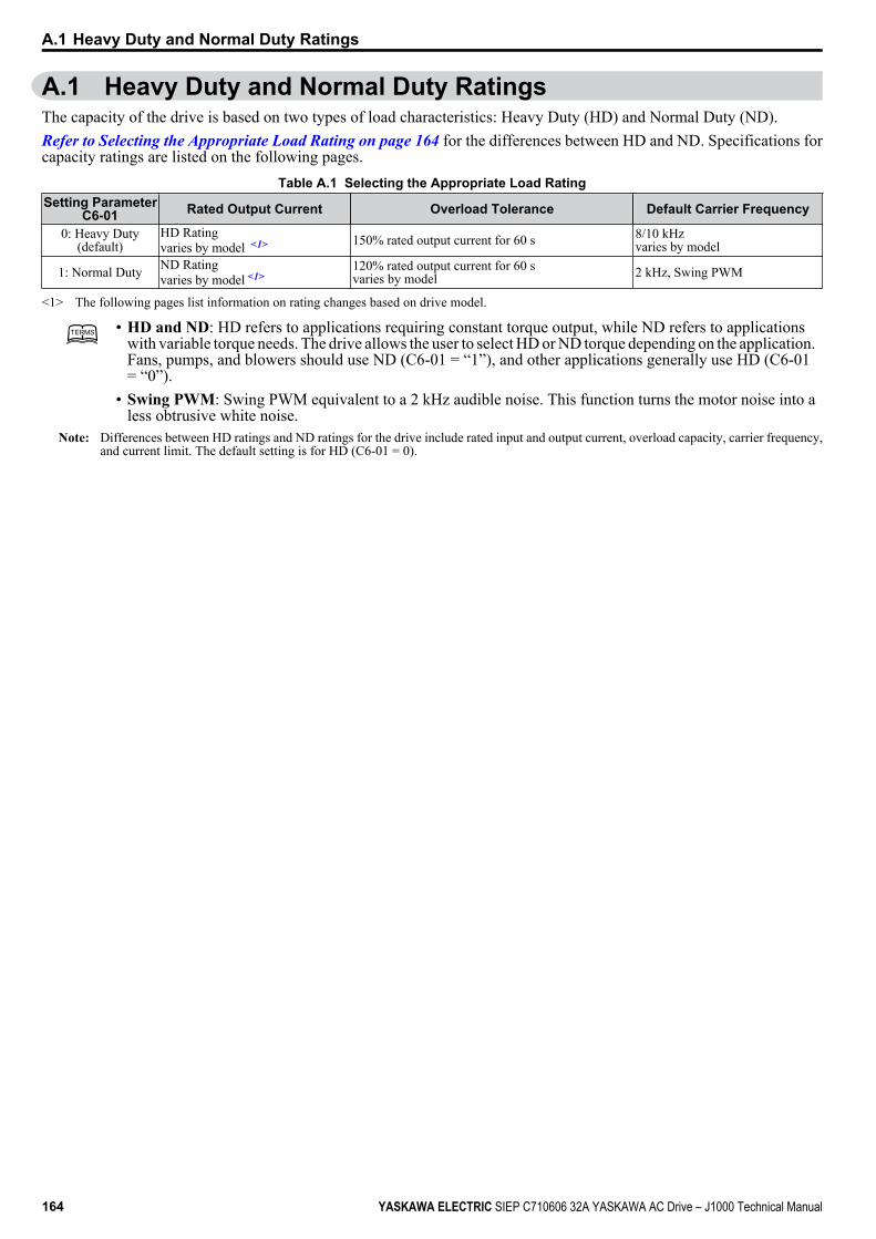
A.1 Heavy Duty and Normal Duty RatingsThe capacity of the drive is based on two types of load characteristics: Heavy Duty (HD) and Normal Duty (ND).Refer to Selecting the Appropriate Load Rating on page 164 for the differences between HD and ND. Specifications forcapacity ratings are listed on the following pages.
Table A.1 Selecting the Appropriate Load RatingSetting Parameter
C6-01 Rated Output Current Overload Tolerance Default Carrier Frequency
0: Heavy Duty(default)
HD Ratingvaries by model <1> 150% rated output current for 60 s 8/10 kHz
varies by model
1: Normal Duty ND Ratingvaries by model <1>
120% rated output current for 60 svaries by model 2 kHz, Swing PWM
<1> The following pages list information on rating changes based on drive model.
TERMSTERMS • HD and ND: HD refers to applications requiring constant torque output, while ND refers to applicationswith variable torque needs. The drive allows the user to select HD or ND torque depending on the application.Fans, pumps, and blowers should use ND (C6-01 = “1”), and other applications generally use HD (C6-01= “0”).
• Swing PWM: Swing PWM equivalent to a 2 kHz audible noise. This function turns the motor noise into aless obtrusive white noise.
Note: Differences between HD ratings and ND ratings for the drive include rated input and output current, overload capacity, carrier frequency,and current limit. The default setting is for HD (C6-01 = 0).
A.1 Heavy Duty and Normal Duty Ratings
164 YASKAWA ELECTRIC SIEP C710606 32A YASKAWA AC Drive – J1000 Technical Manual
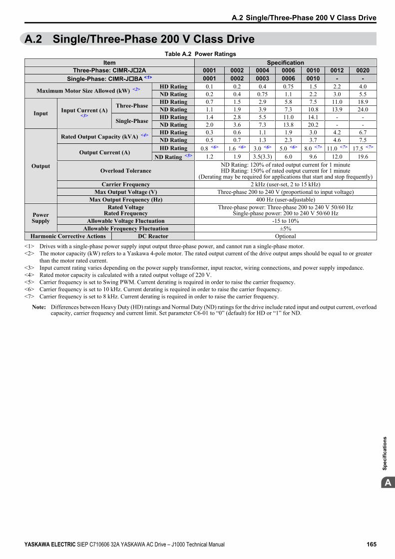
A.2 Single/Three-Phase 200 V Class DriveTable A.2 Power Ratings
Item SpecificationThree-Phase: CIMR-Jo2A 0001 0002 0004 0006 0010 0012 0020
Single-Phase: CIMR-JoBA <1> 0001 0002 0003 0006 0010 - -
Maximum Motor Size Allowed (kW) <2> HD Rating 0.1 0.2 0.4 0.75 1.5 2.2 4.0ND Rating 0.2 0.4 0.75 1.1 2.2 3.0 5.5
Input Input Current (A)<3>
Three-Phase HD Rating 0.7 1.5 2.9 5.8 7.5 11.0 18.9ND Rating 1.1 1.9 3.9 7.3 10.8 13.9 24.0
Single-Phase HD Rating 1.4 2.8 5.5 11.0 14.1 - -ND Rating 2.0 3.6 7.3 13.8 20.2 - -
Output
Rated Output Capacity (kVA) <4> HD Rating 0.3 0.6 1.1 1.9 3.0 4.2 6.7ND Rating 0.5 0.7 1.3 2.3 3.7 4.6 7.5
Output Current (A)HD Rating 0.8 <6> 1.6 <6> 3.0 <6> 5.0 <6> 8.0 <7> 11.0 <7> 17.5 <7>
ND Rating <5> 1.2 1.9 3.5(3.3) 6.0 9.6 12.0 19.6
Overload ToleranceND Rating: 120% of rated output current for 1 minuteHD Rating: 150% of rated output current for 1 minute
(Derating may be required for applications that start and stop frequently)Carrier Frequency 2 kHz (user-set, 2 to 15 kHz)
Max Output Voltage (V) Three-phase 200 to 240 V (proportional to input voltage)Max Output Frequency (Hz) 400 Hz (user-adjustable)
PowerSupply
Rated VoltageRated Frequency
Three-phase power: Three-phase 200 to 240 V 50/60 HzSingle-phase power: 200 to 240 V 50/60 Hz
Allowable Voltage Fluctuation -15 to 10%Allowable Frequency Fluctuation ±5%
Harmonic Corrective Actions DC Reactor Optional
<1> Drives with a single-phase power supply input output three-phase power, and cannot run a single-phase motor.<2> The motor capacity (kW) refers to a Yaskawa 4-pole motor. The rated output current of the drive output amps should be equal to or greater
than the motor rated current.<3> Input current rating varies depending on the power supply transformer, input reactor, wiring connections, and power supply impedance.<4> Rated motor capacity is calculated with a rated output voltage of 220 V.<5> Carrier frequency is set to Swing PWM. Current derating is required in order to raise the carrier frequency.<6> Carrier frequency is set to 10 kHz. Current derating is required in order to raise the carrier frequency.<7> Carrier frequency is set to 8 kHz. Current derating is required in order to raise the carrier frequency.
Note: Differences between Heavy Duty (HD) ratings and Normal Duty (ND) ratings for the drive include rated input and output current, overloadcapacity, carrier frequency and current limit. Set parameter C6-01 to “0” (default) for HD or “1” for ND.
A.2 Single/Three-Phase 200 V Class Drive
YASKAWA ELECTRIC SIEP C710606 32A YASKAWA AC Drive – J1000 Technical Manual 165
A
Spec
ifica
tions

A.3 Three-Phase 400 V Class DrivesTable A.3 Power Ratings
Item SpecificationCIMR-Jo4A 0001 0002 0004 0005 0007 0009 0011
Maximum Applicable Motor Capacity(kW) <1>
HD Rating 0.2 0.4 0.75 1.5 2.2 3.0 4.0ND Rating 0.4 0.75 1.5 2.2 3.0 3.7 5.5
Input Input Current (A) <2> HD Rating 1.2 1.8 3.2 4.4 6.0 8.2 10.4ND Rating 1.2 2.1 4.3 5.9 8.1 9.4 14.0
Output
Output Current (kVA) <3> HD Rating <5> 0.9 1.4 2.6 3.7 4.2 5.5 7.0ND Rating <4> 0.9 1.6 3.1 4.1 5.3 6.7 8.5
Output Current (A) HD Rating <5> 1.2 1.8 3.4 4.8 5.5 7.2 9.2ND Rating <4> 1.2 2.1 4.1 5.4 6.9 8.8 11.1
Overload ToleranceND Rating: 120% of rated output current for 60 sHD Rating: 150% of rated output current for 60 s
(Derating may be required for applications that start and stop frequently)Carrier Frequency 2 kHz (user-adjustable from 2 to 15 kHz)
Maximum Output Voltage (V) Three-phase: 380 to 480 V (proportional to input voltage)Maximum Output Frequency (Hz) 400 Hz (user-adjustable)
PowerSupply
Rated Voltage Rated Frequency Three-phase: 380 to 480 V 50/60 HzAllowable Voltage Fluctuation -15 to 10%
Allowable Frequency Fluctuation ±5%Harmonic Corrective Actions DC Reactor Optional
<1> The motor capacity (kW) refers to a Yaskawa 4-pole motor. The rated output current of the drive output amps should be equal to or greaterthan the motor rated current.
<2> Input current rating varies depending on the power supply transformer, input reactor, wiring conditions, and power supply impedance.<3> Rated motor capacity is calculated with a rated output voltage of 440 V.<4> Carrier frequency is set to Swing PWM. Current derating is required in order to raise the carrier frequency.<5> Carrier frequency is set to 8 kHz. Current derating is required in order to raise the carrier frequency.
Note: Differences between Heavy Duty (HD) ratings and Normal Duty (ND) ratings for the drive include rated input and output current, overloadcapacity, carrier frequency and current limit. Set parameter C6-01 to “0” (default) for HD or “1” for ND.
A.3 Three-Phase 400 V Class Drives
166 YASKAWA ELECTRIC SIEP C710606 32A YASKAWA AC Drive – J1000 Technical Manual
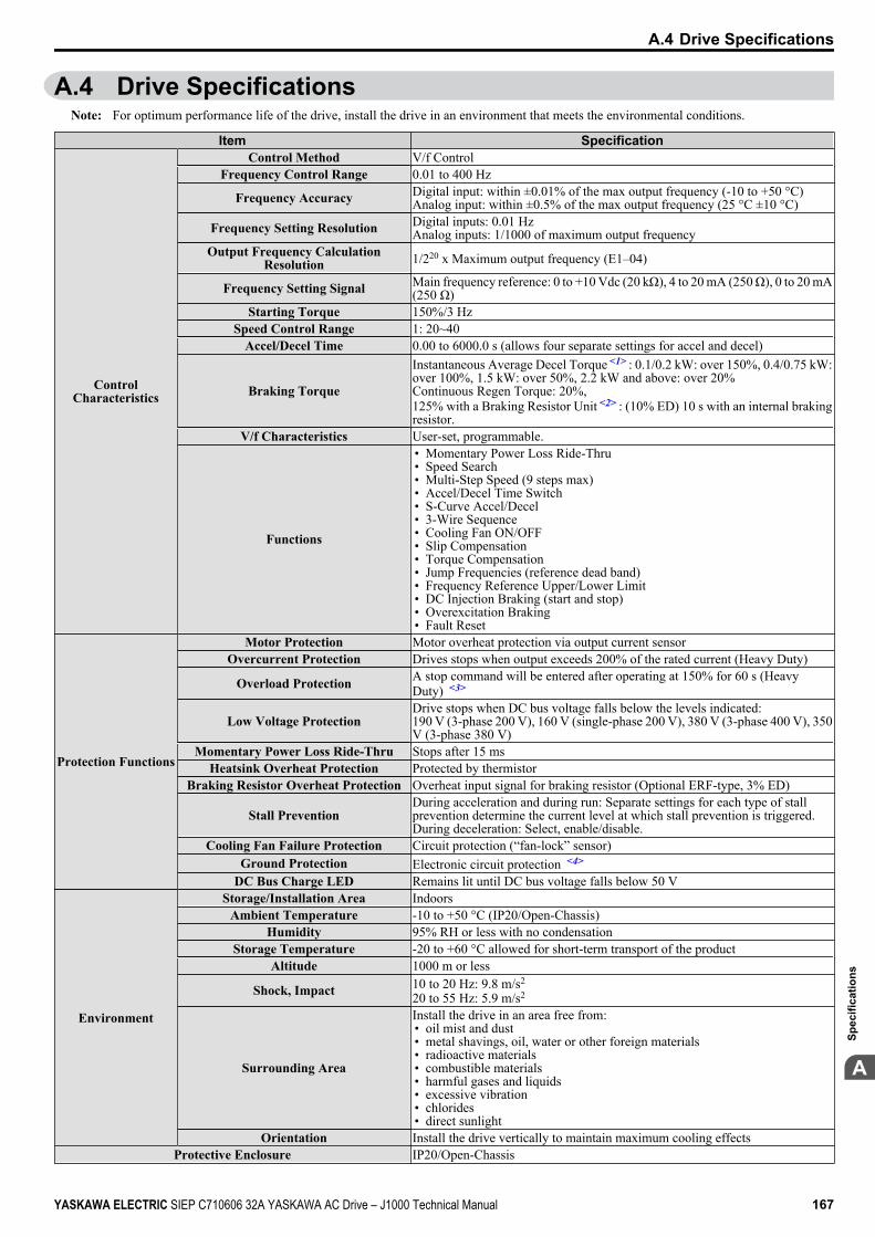
A.4 Drive SpecificationsNote: For optimum performance life of the drive, install the drive in an environment that meets the environmental conditions.
Item Specification
ControlCharacteristics
Control Method V/f ControlFrequency Control Range 0.01 to 400 Hz
Frequency Accuracy Digital input: within ±0.01% of the max output frequency (-10 to +50 °C)Analog input: within ±0.5% of the max output frequency (25 °C ±10 °C)
Frequency Setting Resolution Digital inputs: 0.01 HzAnalog inputs: 1/1000 of maximum output frequency
Output Frequency CalculationResolution 1/220 x Maximum output frequency (E1–04)
Frequency Setting Signal Main frequency reference: 0 to +10 Vdc (20 kΩ), 4 to 20 mA (250 Ω), 0 to 20 mA(250 Ω)
Starting Torque 150%/3 HzSpeed Control Range 1: 20~40
Accel/Decel Time 0.00 to 6000.0 s (allows four separate settings for accel and decel)
Braking Torque
Instantaneous Average Decel Torque <1> : 0.1/0.2 kW: over 150%, 0.4/0.75 kW:over 100%, 1.5 kW: over 50%, 2.2 kW and above: over 20%Continuous Regen Torque: 20%,125% with a Braking Resistor Unit <2> : (10% ED) 10 s with an internal brakingresistor.
V/f Characteristics User-set, programmable.
Functions
• Momentary Power Loss Ride-Thru• Speed Search• Multi-Step Speed (9 steps max)• Accel/Decel Time Switch• S-Curve Accel/Decel• 3-Wire Sequence• Cooling Fan ON/OFF• Slip Compensation• Torque Compensation• Jump Frequencies (reference dead band)• Frequency Reference Upper/Lower Limit• DC Injection Braking (start and stop)• Overexcitation Braking• Fault Reset
Protection Functions
Motor Protection Motor overheat protection via output current sensorOvercurrent Protection Drives stops when output exceeds 200% of the rated current (Heavy Duty)
Overload Protection A stop command will be entered after operating at 150% for 60 s (HeavyDuty) <3>
Low Voltage ProtectionDrive stops when DC bus voltage falls below the levels indicated:190 V (3-phase 200 V), 160 V (single-phase 200 V), 380 V (3-phase 400 V), 350V (3-phase 380 V)
Momentary Power Loss Ride-Thru Stops after 15 msHeatsink Overheat Protection Protected by thermistor
Braking Resistor Overheat Protection Overheat input signal for braking resistor (Optional ERF-type, 3% ED)
Stall PreventionDuring acceleration and during run: Separate settings for each type of stallprevention determine the current level at which stall prevention is triggered.During deceleration: Select, enable/disable.
Cooling Fan Failure Protection Circuit protection (“fan-lock” sensor)Ground Protection Electronic circuit protection <4>
DC Bus Charge LED Remains lit until DC bus voltage falls below 50 V
Environment
Storage/Installation Area IndoorsAmbient Temperature -10 to +50 °C (IP20/Open-Chassis)
Humidity 95% RH or less with no condensationStorage Temperature -20 to +60 °C allowed for short-term transport of the product
Altitude 1000 m or less
Shock, Impact 10 to 20 Hz: 9.8 m/s2
20 to 55 Hz: 5.9 m/s2
Surrounding Area
Install the drive in an area free from:• oil mist and dust• metal shavings, oil, water or other foreign materials• radioactive materials• combustible materials• harmful gases and liquids• excessive vibration• chlorides• direct sunlight
Orientation Install the drive vertically to maintain maximum cooling effectsProtective Enclosure IP20/Open-Chassis
A.4 Drive Specifications
YASKAWA ELECTRIC SIEP C710606 32A YASKAWA AC Drive – J1000 Technical Manual 167
A
Spec
ifica
tions
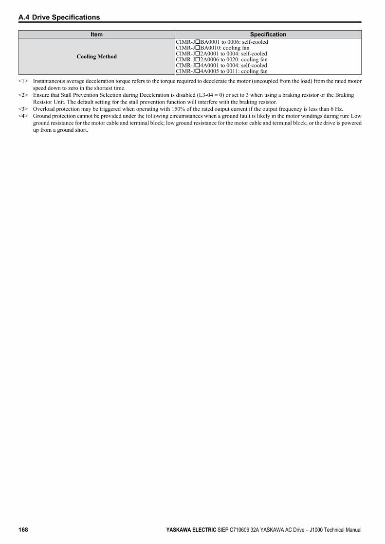
Item Specification
Cooling Method
CIMR-JoBA0001 to 0006: self-cooledCIMR-JoBA0010: cooling fanCIMR-Jo2A0001 to 0004: self-cooledCIMR-Jo2A0006 to 0020: cooling fanCIMR-Jo4A0001 to 0004: self-cooledCIMR-Jo4A0005 to 0011: cooling fan
<1> Instantaneous average deceleration torque refers to the torque required to decelerate the motor (uncoupled from the load) from the rated motorspeed down to zero in the shortest time.
<2> Ensure that Stall Prevention Selection during Deceleration is disabled (L3-04 = 0) or set to 3 when using a braking resistor or the BrakingResistor Unit. The default setting for the stall prevention function will interfere with the braking resistor.
<3> Overload protection may be triggered when operating with 150% of the rated output current if the output frequency is less than 6 Hz.<4> Ground protection cannot be provided under the following circumstances when a ground fault is likely in the motor windings during run: Low
ground resistance for the motor cable and terminal block; low ground resistance for the motor cable and terminal block; or the drive is poweredup from a ground short.
A.4 Drive Specifications
168 YASKAWA ELECTRIC SIEP C710606 32A YASKAWA AC Drive – J1000 Technical Manual
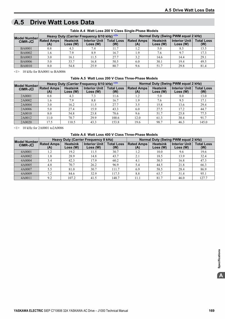
A.5 Drive Watt Loss DataTable A.4 Watt Loss 200 V Class Single-Phase Models
Model NumberCIMR-Jo
Heavy Duty (Carrier Frequency 8/10 kHz) <1> Normal Duty (Swing PWM equal 2 kHz)Rated Amps
(A)HeatsinkLoss (W)
Interior UnitLoss (W)
Total Loss(W)
Rated Amps(A)
HeatsinkLoss (W)
Interior UnitLoss (W)
Total Loss(W)
BA0001 0.8 4.3 7.4 11.7 1.2 5.0 8.5 13.5BA0002 1.6 7.9 8.9 16.7 1.9 7.6 9.7 17.3BA0003 3.0 16.1 11.5 27.7 3.2 14.6 14.4 29.1BA0006 5.0 33.7 16.8 50.5 6.0 30.1 19.4 49.5BA0010 8.0 54.8 25.9 80.7 9.6 51.7 29.8 81.4
<1> 10 kHz for BA0001 to BA0006
Table A.5 Watt Loss 200 V Class Three-Phase Models
Model NumberCIMR-Jo
Heavy Duty (Carrier Frequency 8/10 kHz) <1> Normal Duty (Swing PWM equal 2 kHz)Rated Amps
(A)HeatsinkLoss (W)
Interior UnitLoss (W)
Total Loss(W)
Rated Amps(A)
HeatsinkLoss (W)
Interior UnitLoss (W)
Total Loss(W)
2A0001 0.8 4.3 7.3 11.6 1.2 5.0 8.0 13.02A0002 1.6 7.9 8.8 16.7 1.9 7.6 9.5 17.12A0004 3.0 16.2 11.5 27.7 3.5 15.8 13.6 29.42A0006 5.0 27.4 15.9 43.3 6.0 27.5 17.2 44.72A0010 8.0 54.8 23.8 78.6 9.6 51.7 25.8 77.52A0012 11.0 70.7 29.9 100.6 12.0 61.3 30.4 91.72A0020 17.5 110.5 43.3 153.8 19.6 98.7 46.3 145.0
<1> 10 kHz for 2A0001 to2A0006
Table A.6 Watt Loss 400 V Class Three-Phase Models
Model NumberCIMR-Jo
Heavy Duty (Carrier Frequency 8 kHz) Normal Duty (Swing PWM equal 2 kHz)Rated Amps
(A)HeatsinkLoss (W)
Interior UnitLoss (W)
Total Loss(W)
Rated Amps(A)
HeatsinkLoss (W)
Interior UnitLoss (W)
Total Loss(W)
4A0001 1.2 19.2 11.5 30.7 1.2 10.0 9.6 19.64A0002 1.8 28.9 14.8 43.7 2.1 18.5 13.9 32.44A0004 3.4 42.3 17.9 60.2 4.1 30.5 16.8 47.34A0005 4.8 70.7 26.2 96.9 5.4 44.5 21.8 66.34A0007 5.5 81.0 30.7 111.7 6.9 58.5 28.4 86.94A0009 7.2 84.6 32.9 117.5 8.8 63.7 31.4 95.14A0011 9.2 107.2 41.5 148.7 11.1 81.7 46.0 127.7
A.5 Drive Watt Loss Data
YASKAWA ELECTRIC SIEP C710606 32A YASKAWA AC Drive – J1000 Technical Manual 169
A
Spec
ifica
tions
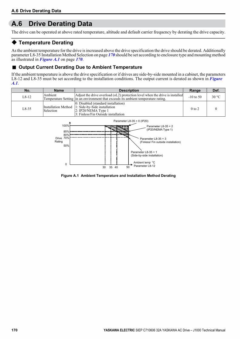
A.6 Drive Derating DataThe drive can be operated at above rated temperature, altitude and default carrier frequency by derating the drive capacity.
u Temperature DeratingAs the ambient temperature for the drive is increased above the drive specification the drive should be derated. Additionallyparameter L8-35 Installation Method Selection on page 170 should be set according to enclosure type and mounting methodas illustrated in Figure A.1 on page 170.
n Output Current Derating Due to Ambient TemperatureIf the ambient temperature is above the drive specification or if drives are side-by-side mounted in a cabinet, the parametersL8-12 and L8-35 must be set according to the installation conditions. The output current is derated as shown in Figure A.1.
No. Name Description Range Def.
L8-12 AmbientTemperature Setting
Adjust the drive overload (oL2) protection level when the drive is installedin an environment that exceeds its ambient temperature rating. -10 to 50 30 °C
L8-35 Installation MethodSelection
0: Disabled (standard installation)1: Side-by-Side installation2: IP20/NEMA Type 13: Finless/Fin Outside installation
0 to 2 0
40 500
30 35
50%
70%80%85%
100%
Drive Rating
Ambient temp C Parameter L8-12
o
Parameter L8-35 = 0 (IP20)
Parameter L8-35 = 2 (IP20/NEMA Type 1)
Parameter L8-35 = 1 (Side-by-side installation)
Parameter L8-35 = 3 (Finless/ Fin outside installation)
Figure A.1 Ambient Temperature and Installation Method Derating
A.6 Drive Derating Data
170 YASKAWA ELECTRIC SIEP C710606 32A YASKAWA AC Drive – J1000 Technical Manual
Parameter ListThis appendix contains a full listing of all parameters and settings available in the drive.
B.1 PARAMETER GROUPS..................................................................................172B.2 PARAMETER TABLE.....................................................................................173B.3 DEFAULTS BY DRIVE CAPACITY (O2-04) AND ND/HD (C6-01).................185
Appendix: B
YASKAWA ELECTRIC SIEP C710606 32A YASKAWA AC Drive – J1000 Technical Manual 171
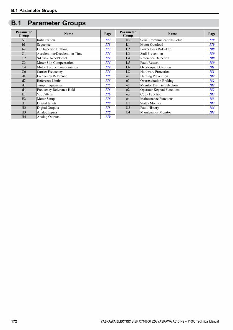
B.1 Parameter GroupsParameter
Group Name Page
ParameterGroup Name Page
A1 Initialization 173 H5 Serial Communications Setup 179b1 Sequence 173 L1 Motor Overload 179b2 DC Injection Braking 173 L2 Power Loss Ride-Thru 180C1 Acceleration/Deceleration Time 174 L3 Stall Prevention 180C2 S-Curve Accel/Decel 174 L4 Reference Detection 180C3 Motor Slip Compensation 174 L5 Fault Restart 180C4 Motor Torque Compensation 174 L6 Overtorque Detection 181C6 Carrier Frequency 174 L8 Hardware Protection 181d1 Frequency Reference 175 n1 Hunting Prevention 182d2 Reference Limits 175 n3 Overexcitation Braking 182d3 Jump Frequencies 175 o1 Monitor Display Selection 182d4 Frequency Reference Hold 176 o2 Operator Keypad Functions 182E1 V/f Pattern 176 o3 Copy Function 183E2 Motor Setup 176 o4 Maintenance Functions 183H1 Digital Inputs 177 U1 Status Monitor 183H2 Digital Outputs 178 U2 Fault History 184H3 Analog Inputs 178 U4 Maintenance Monitor 184H4 Analog Outputs 179
B.1 Parameter Groups
172 YASKAWA ELECTRIC SIEP C710606 32A YASKAWA AC Drive – J1000 Technical Manual
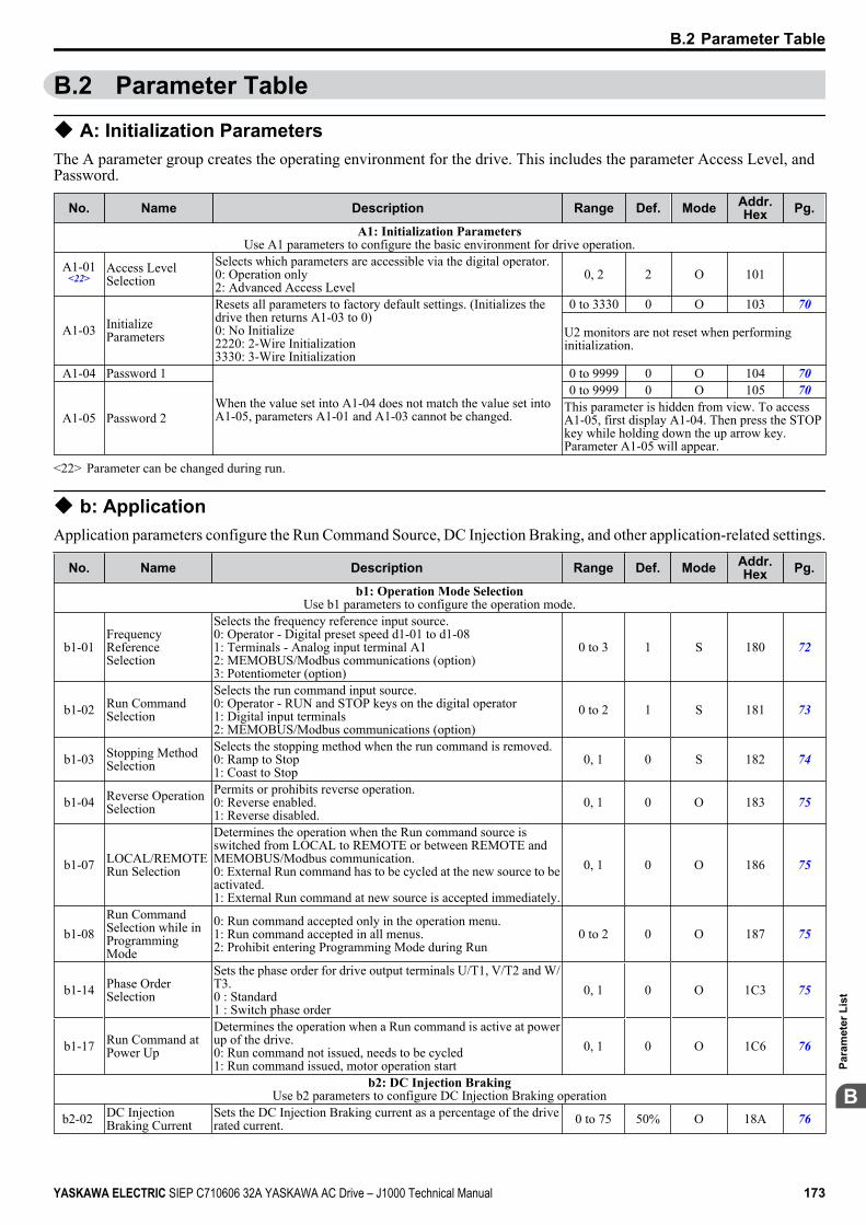
B.2 Parameter Table
u A: Initialization ParametersThe A parameter group creates the operating environment for the drive. This includes the parameter Access Level, andPassword.
No. Name Description Range Def. Mode Addr.Hex Pg.
A1: Initialization ParametersUse A1 parameters to configure the basic environment for drive operation.
A1-01<22>
Access LevelSelection
Selects which parameters are accessible via the digital operator.0: Operation only2: Advanced Access Level
0, 2 2 O 101
A1-03 InitializeParameters
Resets all parameters to factory default settings. (Initializes thedrive then returns A1-03 to 0)0: No Initialize2220: 2-Wire Initialization3330: 3-Wire Initialization
0 to 3330 0 O 103 70
U2 monitors are not reset when performinginitialization.
A1-04 Password 1
When the value set into A1-04 does not match the value set intoA1-05, parameters A1-01 and A1-03 cannot be changed.
0 to 9999 0 O 104 70
A1-05 Password 2
0 to 9999 0 O 105 70This parameter is hidden from view. To accessA1-05, first display A1-04. Then press the STOPkey while holding down the up arrow key.Parameter A1-05 will appear.
<22> Parameter can be changed during run.
u b: ApplicationApplication parameters configure the Run Command Source, DC Injection Braking, and other application-related settings.
No. Name Description Range Def. Mode Addr.Hex Pg.
b1: Operation Mode SelectionUse b1 parameters to configure the operation mode.
b1-01FrequencyReferenceSelection
Selects the frequency reference input source.0: Operator - Digital preset speed d1-01 to d1-081: Terminals - Analog input terminal A12: MEMOBUS/Modbus communications (option)3: Potentiometer (option)
0 to 3 1 S 180 72
b1-02 Run CommandSelection
Selects the run command input source.0: Operator - RUN and STOP keys on the digital operator1: Digital input terminals2: MEMOBUS/Modbus communications (option)
0 to 2 1 S 181 73
b1-03 Stopping MethodSelection
Selects the stopping method when the run command is removed.0: Ramp to Stop1: Coast to Stop
0, 1 0 S 182 74
b1-04 Reverse OperationSelection
Permits or prohibits reverse operation.0: Reverse enabled.1: Reverse disabled.
0, 1 0 O 183 75
b1-07 LOCAL/REMOTERun Selection
Determines the operation when the Run command source isswitched from LOCAL to REMOTE or between REMOTE andMEMOBUS/Modbus communication.0: External Run command has to be cycled at the new source to beactivated.1: External Run command at new source is accepted immediately.
0, 1 0 O 186 75
b1-08Run CommandSelection while inProgrammingMode
0: Run command accepted only in the operation menu.1: Run command accepted in all menus.2: Prohibit entering Programming Mode during Run
0 to 2 0 O 187 75
b1-14 Phase OrderSelection
Sets the phase order for drive output terminals U/T1, V/T2 and W/T3.0 : Standard1 : Switch phase order
0, 1 0 O 1C3 75
b1-17 Run Command atPower Up
Determines the operation when a Run command is active at powerup of the drive.0: Run command not issued, needs to be cycled1: Run command issued, motor operation start
0, 1 0 O 1C6 76
b2: DC Injection BrakingUse b2 parameters to configure DC Injection Braking operation
b2-02 DC InjectionBraking Current
Sets the DC Injection Braking current as a percentage of the driverated current. 0 to 75 50% O 18A 76
B.2 Parameter Table
YASKAWA ELECTRIC SIEP C710606 32A YASKAWA AC Drive – J1000 Technical Manual 173
B
Para
met
er L
ist

No. Name Description Range Def. Mode Addr.Hex Pg.
b2-03 DC InjectionBraking Time/DCExcitation Time atStart
Sets DC Injection Braking time at start. Disabled when set to 0.00seconds.
0.00 to10.00 0.00 s O 18B 76
b2-04 DC InjectionBraking Time atStop
Sets DC Injection Braking time at stop.When b1-03 = 0, this parameter sets the amount of DC Injectiontime applied to the motor at the end of the decel ramp. Disabledwhen set to 0.00.
0.00 to10.00 0.50 s O 18C 76
u C: TuningC parameters are used to adjust the acceleration and deceleration times, S-curves, slip and torque compensation functionsand carrier frequency selections.
No. Name Description Range Def. Mode Addr.Hex Pg.
C1: Acceleration and Deceleration TimesUse C1 parameters to configure motor acceleration and deceleration.
C1-01<22>
Acceleration Time1 Sets the time to accelerate from 0 to maximum frequency.
0.0 to6000.0 10.0 s
S 200 77
C1-02<22>
Deceleration Time1 Sets the time to decelerate from maximum frequency to 0. S 201 77
C1-03<22>
Acceleration Time2
Sets the time to accelerate from 0 to maximum frequency whenAccel/Decel times 2 are selected by a digital input. O 202 77
C1-04<22>
Deceleration Time2
Sets the time to decelerate from maximum frequency to 0 whenAccel/Decel times 2 are selected by a digital input. O 203 77
C1-09 Fast-Stop Time Sets the time to decelerate from maximum frequency to 0 for themulti-function input fast-stop function.Note: This parameter is also used by selecting “Fast-Stop” as a StopMethod when a fault is detected.
O 208 77
C2: S-Curve CharacteristicsUse C2 parameters to configure S-curve operation.
C2-01 S-CurveCharacteristic atAccel Start
The S-curve can be controlled in the four points shown below.
Run command
Output frequency
Time
C2-01C2-04
C2-02 C2-03
ON OFF
S-curve is used to further soften the starting and stopping ramp. Thelonger the S-curve time, the softer the starting and stopping ramp.
0.00 to10.00 0.20 s O 20B 78
C2-02 S-CurveCharacteristic atAccel End
0.00 to10.00 0.20 s O 20C 78
C2-03 S-CurveCharacteristic atDecel Start
0.00 to10.00 0.20 s O 20D 78
C2-04 S-CurveCharacteristic atDecel End
0.00 to10.00 0.00 s O 20E 78
C3: Slip CompensationUse C3 parameters to configure the slip compensation function.
C3-01<22>
Slip CompensationGain
Sets the slip compensation gain. Decides for what amount the outputfrequency is boosted in order to compensate the slip.Note: Adjustment is not normally required.
0.0 to 2.5 0.0 O 20F 78
C3-02 Slip CompensationPrimary DelayTime
Adjusts the slip compensation function delay time.Decrease the setting when the slip compensation response is tooslow, increase it when the speed is not stable.
0 to 10000 2000ms O 210 78
C4: Torque CompensationUse C4 parameters to configure Torque Compensation function.
C4-01<22>
TorqueCompensationGain
Sets the gain for the automatic torque (voltage) boost function andhelps to produce better starting torque.Increase this setting when using a long motor cable or when themotor is significantly smaller than the drive capacity.Decrease this setting when motor oscillation occurs. Set the valueso that the current at low speed does not exceeds the drive ratedcurrent.
0.00 to2.50 1.00 O 215 78
C6: Carrier FrequencyUse C6 parameters to configure the carrier frequency drive settings.
C6-01 Normal/HeavyDuty Selection
Selects the load rating for the drive.0: Heavy Duty (HD) for constant torque applications.1: Normal Duty (ND) for variable torque applications.This setting affects the Rated output current and overload toleranceof the drive.
0, 1 0 S 223 79
B.2 Parameter Table
174 YASKAWA ELECTRIC SIEP C710606 32A YASKAWA AC Drive – J1000 Technical Manual
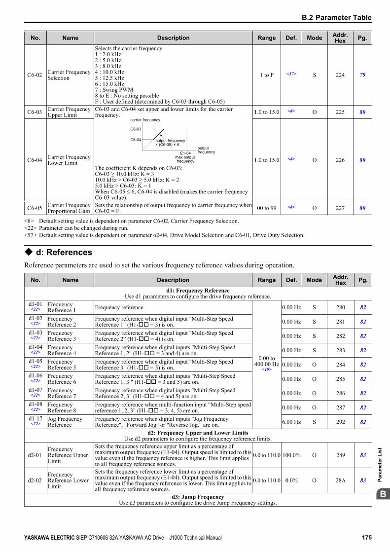
No. Name Description Range Def. Mode Addr.Hex Pg.
C6-02 Carrier FrequencySelection
Selects the carrier frequency1 : 2.0 kHz2 : 5.0 kHz3 : 8.0 kHz4 : 10.0 kHz5 : 12.5 kHz6 : 15.0 kHz7 : Swing PWM8 to E : No setting possibleF : User defined (determined by C6-03 through C6-05)
1 to F <57> S 224 79
C6-03 Carrier FrequencyUpper Limit
C6-03 and C6-04 set upper and lower limits for the carrierfrequency.
carrier frequency
E1-04max output frequency
output frequency× (C6-05) × K
output frequency
C6-03
C6-04
The coefficient K depends on C6-03:C6-03 ≥ 10.0 kHz: K = 310.0 kHz > C6-03 ≥ 5.0 kHz: K = 25.0 kHz > C6-03: K = 1When C6-05 ≤ 6, C6-04 is disabled (makes the carrier frequencyC6-03 value).
1.0 to 15.0 <8> O 225 80
C6-04 Carrier FrequencyLower Limit 1.0 to 15.0 <8> O 226 80
C6-05 Carrier FrequencyProportional Gain
Sets the relationship of output frequency to carrier frequency whenC6-02 = F. 00 to 99 <8> O 227 80
<8> Default setting value is dependent on parameter C6-02, Carrier Frequency Selection.<22> Parameter can be changed during run.<57> Default setting value is dependent on parameter o2-04, Drive Model Selection and C6-01, Drive Duty Selection.
u d: ReferencesReference parameters are used to set the various frequency reference values during operation.
No. Name Description Range Def. Mode Addr.Hex Pg.
d1: Frequency ReferenceUse d1 parameters to configure the drive frequency reference.
d1-01<22>
FrequencyReference 1 Frequency reference
0.00 to400.00 Hz
<19>
0.00 Hz S 280 82
d1-02<22>
FrequencyReference 2
Frequency reference when digital input "Multi-Step SpeedReference 1" (H1-oo = 3) is on. 0.00 Hz S 281 82
d1-03<22>
FrequencyReference 3
Frequency reference when digital input "Multi-Step SpeedReference 2” (H1-oo = 4) is on. 0.00 Hz S 282 82
d1-04<22>
FrequencyReference 4
Frequency reference when digital inputs "Multi-Step SpeedReference 1, 2" (H1-oo = 3 and 4) are on. 0.00 Hz S 283 82
d1-05<22>
FrequencyReference 5
Frequency reference when digital input "Multi-Step SpeedReference 3" (H1-oo = 5) is on. 0.00 Hz O 284 82
d1-06<22>
FrequencyReference 6
Frequency reference when digital inputs "Multi-Step SpeedReference 1, 3 " (H1-oo = 3 and 5) are on. 0.00 Hz O 285 82
d1-07<22>
FrequencyReference 7
Frequency reference when digital inputs "Multi-Step SpeedReference 2, 3" (H1-oo = 4 and 5) are on. 0.00 Hz O 286 82
d1-08<22>
FrequencyReference 8
Frequency reference when multi-function input "Multi-Step speedreference 1, 2, 3" (H1-oo = 3, 4, 5) are on. 0.00 Hz O 287 82
d1-17<22>
Jog FrequencyReference
Frequency reference when digital inputs "Jog FrequencyReference", "Forward Jog" or "Reverse Jog." are on. 6.00 Hz S 292 82
d2: Frequency Upper and Lower LimitsUse d2 parameters to configure the frequency reference limits.
d2-01 FrequencyReference UpperLimit
Sets the frequency reference upper limit as a percentage ofmaximum output frequency (E1-04). Output speed is limited to thisvalue even if the frequency reference is higher. This limit appliesto all frequency reference sources.
0.0 to 110.0 100.0% O 289 83
d2-02 FrequencyReference LowerLimit
Sets the frequency reference lower limit as a percentage ofmaximum output frequency (E1-04). Output speed is limited to thisvalue even if the frequency reference is lower. This limit applies toall frequency reference sources.
0.0 to 110.0 0.0% O 28A 83
d3: Jump FrequencyUse d3 parameters to configure the drive Jump Frequency settings.
B.2 Parameter Table
YASKAWA ELECTRIC SIEP C710606 32A YASKAWA AC Drive – J1000 Technical Manual 175
B
Para
met
er L
ist
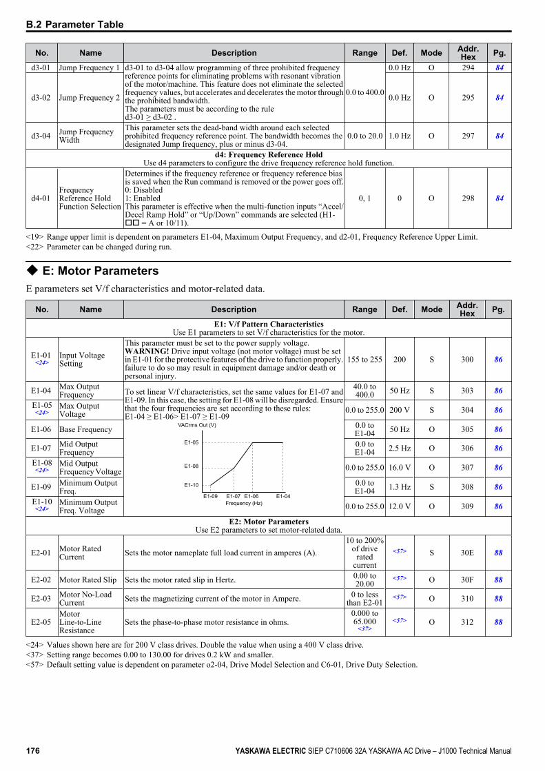
No. Name Description Range Def. Mode Addr.Hex Pg.
d3-01 Jump Frequency 1 d3-01 to d3-04 allow programming of three prohibited frequencyreference points for eliminating problems with resonant vibrationof the motor/machine. This feature does not eliminate the selectedfrequency values, but accelerates and decelerates the motor throughthe prohibited bandwidth.The parameters must be according to the ruled3-01 ≥ d3-02 .
0.0 to 400.0
0.0 Hz O 294 84
d3-02 Jump Frequency 2 0.0 Hz O 295 84
d3-04 Jump FrequencyWidth
This parameter sets the dead-band width around each selectedprohibited frequency reference point. The bandwidth becomes thedesignated Jump frequency, plus or minus d3-04.
0.0 to 20.0 1.0 Hz O 297 84
d4: Frequency Reference HoldUse d4 parameters to configure the drive frequency reference hold function.
d4-01 FrequencyReference HoldFunction Selection
Determines if the frequency reference or frequency reference biasis saved when the Run command is removed or the power goes off.0: Disabled1: EnabledThis parameter is effective when the multi-function inputs “Accel/Decel Ramp Hold” or “Up/Down” commands are selected (H1-oo = A or 10/11).
0, 1 0 O 298 84
<19> Range upper limit is dependent on parameters E1-04, Maximum Output Frequency, and d2-01, Frequency Reference Upper Limit.<22> Parameter can be changed during run.
u E: Motor ParametersE parameters set V/f characteristics and motor-related data.
No. Name Description Range Def. Mode Addr.Hex Pg.
E1: V/f Pattern CharacteristicsUse E1 parameters to set V/f characteristics for the motor.
E1-01 <24>
Input VoltageSetting
This parameter must be set to the power supply voltage.WARNING! Drive input voltage (not motor voltage) must be setin E1-01 for the protective features of the drive to function properly.failure to do so may result in equipment damage and/or death orpersonal injury.
155 to 255 200 S 300 86
E1-04 Max OutputFrequency To set linear V/f characteristics, set the same values for E1-07 and
E1-09. In this case, the setting for E1-08 will be disregarded. Ensurethat the four frequencies are set according to these rules:E1-04 ≥ E1-06> E1-07 ≥ E1-09
E1-05
E1-08
E1-10
E1-09 E1-07 E1-06 E1-04
VACrms Out (V)
Frequency (Hz)
40.0 to400.0 50 Hz S 303 86
E1-05<24>
Max OutputVoltage 0.0 to 255.0 200 V S 304 86
E1-06 Base Frequency 0.0 toE1-04 50 Hz O 305 86
E1-07 Mid OutputFrequency
0.0 toE1-04 2.5 Hz O 306 86
E1-08<24>
Mid OutputFrequency Voltage 0.0 to 255.0 16.0 V O 307 86
E1-09 Minimum OutputFreq.
0.0 toE1-04 1.3 Hz S 308 86
E1-10<24>
Minimum OutputFreq. Voltage 0.0 to 255.0 12.0 V O 309 86
E2: Motor ParametersUse E2 parameters to set motor-related data.
E2-01 Motor RatedCurrent Sets the motor nameplate full load current in amperes (A).
10 to 200%of drive
ratedcurrent
<57> S 30E 88
E2-02 Motor Rated Slip Sets the motor rated slip in Hertz. 0.00 to20.00
<57> O 30F 88
E2-03 Motor No-LoadCurrent Sets the magnetizing current of the motor in Ampere. 0 to less
than E2-01<57> O 310 88
E2-05 MotorLine-to-LineResistance
Sets the phase-to-phase motor resistance in ohms.0.000 to65.000
<37><57> O 312 88
<24> Values shown here are for 200 V class drives. Double the value when using a 400 V class drive.<37> Setting range becomes 0.00 to 130.00 for drives 0.2 kW and smaller.<57> Default setting value is dependent on parameter o2-04, Drive Model Selection and C6-01, Drive Duty Selection.
B.2 Parameter Table
176 YASKAWA ELECTRIC SIEP C710606 32A YASKAWA AC Drive – J1000 Technical Manual
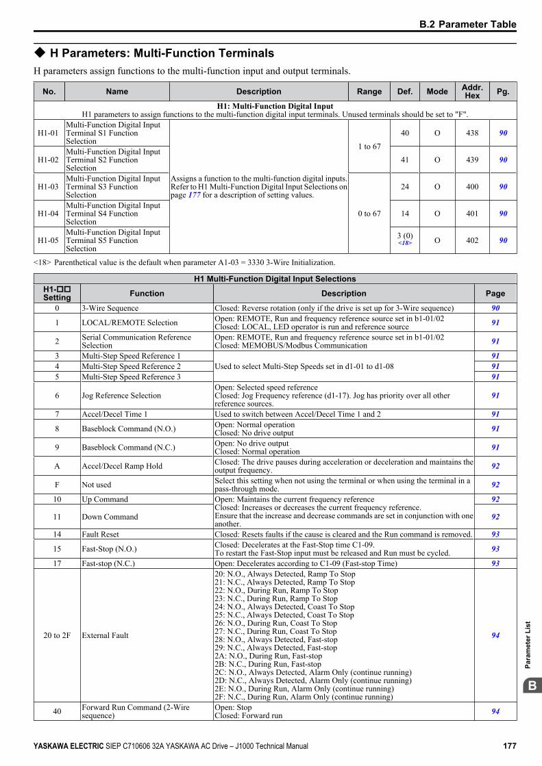
u H Parameters: Multi-Function TerminalsH parameters assign functions to the multi-function input and output terminals.
No. Name Description Range Def. Mode Addr.Hex Pg.
H1: Multi-Function Digital InputH1 parameters to assign functions to the multi-function digital input terminals. Unused terminals should be set to "F".
H1-01 Multi-Function Digital InputTerminal S1 FunctionSelection
Assigns a function to the multi-function digital inputs.Refer to H1 Multi-Function Digital Input Selections onpage 177 for a description of setting values.
1 to 6740 O 438 90
H1-02 Multi-Function Digital InputTerminal S2 FunctionSelection
41 O 439 90
H1-03 Multi-Function Digital InputTerminal S3 FunctionSelection
0 to 67
24 O 400 90
H1-04 Multi-Function Digital InputTerminal S4 FunctionSelection
14 O 401 90
H1-05 Multi-Function Digital InputTerminal S5 FunctionSelection
3 (0)<18> O 402 90
<18> Parenthetical value is the default when parameter A1-03 = 3330 3-Wire Initialization.
H1 Multi-Function Digital Input SelectionsH1-ooSetting Function Description Page
0 3-Wire Sequence Closed: Reverse rotation (only if the drive is set up for 3-Wire sequence) 90
1 LOCAL/REMOTE Selection Open: REMOTE, Run and frequency reference source set in b1-01/02Closed: LOCAL, LED operator is run and reference source 91
2 Serial Communication ReferenceSelection
Open: REMOTE, Run and frequency reference source set in b1-01/02Closed: MEMOBUS/Modbus Communication 91
3 Multi-Step Speed Reference 1 Used to select Multi-Step Speeds set in d1-01 to d1-08
914 Multi-Step Speed Reference 2 915 Multi-Step Speed Reference 3 91
6 Jog Reference Selection Open: Selected speed referenceClosed: Jog Frequency reference (d1-17). Jog has priority over all otherreference sources.
91
7 Accel/Decel Time 1 Used to switch between Accel/Decel Time 1 and 2 91
8 Baseblock Command (N.O.) Open: Normal operationClosed: No drive output 91
9 Baseblock Command (N.C.) Open: No drive outputClosed: Normal operation 91
A Accel/Decel Ramp Hold Closed: The drive pauses during acceleration or deceleration and maintains theoutput frequency. 92
F Not used Select this setting when not using the terminal or when using the terminal in apass-through mode. 92
10 Up Command Open: Maintains the current frequency referenceClosed: Increases or decreases the current frequency reference.Ensure that the increase and decrease commands are set in conjunction with oneanother.
92
11 Down Command 92
14 Fault Reset Closed: Resets faults if the cause is cleared and the Run command is removed. 93
15 Fast-Stop (N.O.) Closed: Decelerates at the Fast-Stop time C1-09.To restart the Fast-Stop input must be released and Run must be cycled. 93
17 Fast-stop (N.C.) Open: Decelerates according to C1-09 (Fast-stop Time) 93
20 to 2F External Fault
20: N.O., Always Detected, Ramp To Stop21: N.C., Always Detected, Ramp To Stop22: N.O., During Run, Ramp To Stop23: N.C., During Run, Ramp To Stop24: N.O., Always Detected, Coast To Stop25: N.C., Always Detected, Coast To Stop26: N.O., During Run, Coast To Stop27: N.C., During Run, Coast To Stop28: N.O., Always Detected, Fast-stop29: N.C., Always Detected, Fast-stop2A: N.O., During Run, Fast-stop2B: N.C., During Run, Fast-stop2C: N.O., Always Detected, Alarm Only (continue running)2D: N.C., Always Detected, Alarm Only (continue running)2E: N.O., During Run, Alarm Only (continue running)2F: N.C., During Run, Alarm Only (continue running)
94
40 Forward Run Command (2-Wiresequence)
Open: StopClosed: Forward run 94
B.2 Parameter Table
YASKAWA ELECTRIC SIEP C710606 32A YASKAWA AC Drive – J1000 Technical Manual 177
B
Para
met
er L
ist

H1 Multi-Function Digital Input SelectionsH1-ooSetting Function Description Page
41 Reverse Run Command (2-Wiresequence)
Open: StopClosed: Reverse run 94
61 External Search Command 1 Closed: Activates Current Detection Speed Search from the max. outputfrequency (E1-04) 94
62 External Search Command 2 Closed: Activates Current Detection Speed Search from the frequency reference 9467 Communications Test Mode Tests the MEMOBUS/Modbus RS-422/485 interface. 95
No. Name Description Range Def. Mode Addr.Hex Pg.
H2: Multi-Function Digital Output MA-MB-MCUse H2 parameters to assign functions to the multi-function digital output MA-MB-MC.
H2-01 Terminal MA, MBand MC FunctionSelection (relay)
Refer to H2 Multi-Function Digital Output Settings on page 178for a description of setting values. 0 to 13D E O 40B 95
H2 Multi-Function Digital Output SettingsH2-01
Setting Function Description Page
0 During Run Closed: A Run command is active or voltage is output 951 Zero Speed Closed: Output frequency is 0 95
2 Speed Agree 1 Closed: Output frequency equals the speed reference (plus or minus 2 Hzhysteresis) 96
4 Frequency Detection 1 Closed: Output frequency is less than or equal to the value in L4-01 with 2 Hzhysteresis 96
5 Frequency Detection 2 Closed: Output frequency is greater than the value in L4-01 with 2 Hz hysteresis 96
6 Drive Ready Closed: Drive Ready. The drive is powered up, not in a fault state, and in theDrive mode 97
7 DC Bus Undervoltage Closed: DC bus voltage is below the Uv trip level 978 During Baseblock (N.O.) Closed: There is no output voltage 97
B Torque Detection 1 (N.O.) Closed: Output current/torque exceeds the torque value set in parameter L6-02for longer than the time set in parameter L6-03 97
E Fault Closed: Fault occurred (other than CPF00 and CPF01) 97
F Not used Set this value when the terminal is not used, or when using the terminal in thepass-through mode 97
10 Minor Fault Closed: An alarm is triggered 97
17 Torque Detection 1 (N.C.) Open: When the output current exceeds the value set in parameter L6-02 formore time than is set in parameter L6-03 97
1A Reverse Direction Closed: Drive is running in the reverse direction 981E Restart Enabled Closed: An automatic restart is performed 98
3C LOCAL/REMOTE Status Closed: LOCALOpen: REMOTE 98
3D Speed Search Closed: Speed search is being executed 98
100 to 102;104 to 108;10B, 10E,110, 117,11A, 11E,13C, 13D
H2 Parameter Functions ReversedOutput Switching of 0 to 13D
Reverse the output switching of the multi-function output functions. Set the lasttwo digits of 1oo to reverse the output signal of that specific functionExamples:Setting “108” reverses the output of “During baseblock”, which is setting value08Setting “13C” reverses the output of “LOCAL/REMOTE Status”, which issetting “3C”
98
No. Name Description Range Def. Mode Addr.Hex Pg.
H3: Analog Input A1Use H3 parameters to set the analog input terminal A1.
H3-01 Terminal A1Signal LevelSelection
Sets the input level for terminal A1.0: 0 to +10 V (lower limit)1: 0 to +10 V (no lower limit)2: 4 to 20 mA3: 0 to 20 mA
0 to 3 0 O 410 98
H3-03<22>
Terminal A1 GainSetting
Sets the level of the input value when 10 V (20 mA) is input atterminal A1.
-999.9 to999.9 100.0% O 411 99
H3-04<22>
Terminal A1 BiasSetting
Sets the level of the input value when 0 V (0 or 4 mA) is input atterminal A1.
-999.9 to999.9 0.0% O 412 99
H3-13 Analog Input FilterTime Constant
Sets the primary delay filter time constant for terminal A1 orpotentiometer (optional). Used for noise filtering. 0.00 to 2.00 0.03 s O 41B 101
<22> Parameter can be changed during run.
B.2 Parameter Table
178 YASKAWA ELECTRIC SIEP C710606 32A YASKAWA AC Drive – J1000 Technical Manual
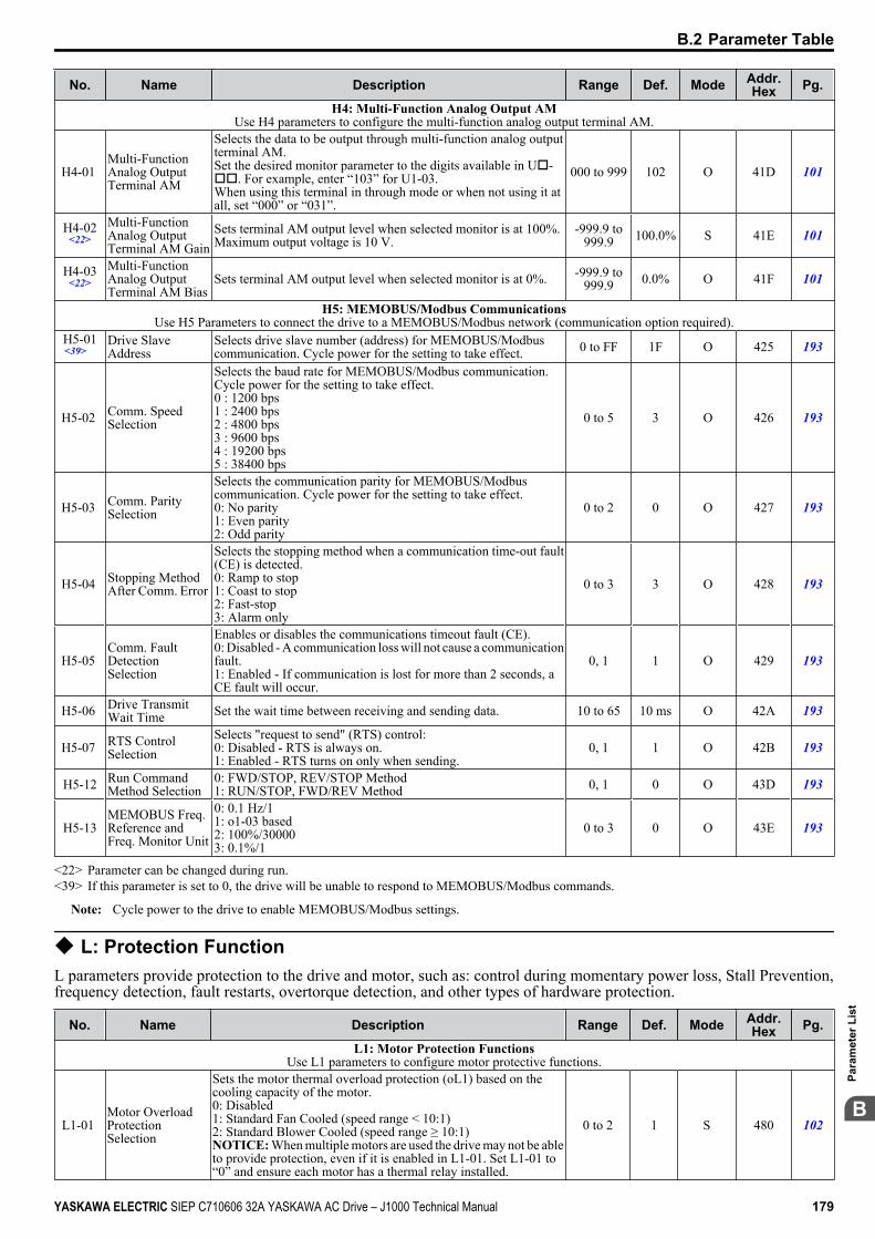
No. Name Description Range Def. Mode Addr.Hex Pg.
H4: Multi-Function Analog Output AMUse H4 parameters to configure the multi-function analog output terminal AM.
H4-01 Multi-FunctionAnalog OutputTerminal AM
Selects the data to be output through multi-function analog outputterminal AM.Set the desired monitor parameter to the digits available in Uo-oo. For example, enter “103” for U1-03.When using this terminal in through mode or when not using it atall, set “000” or “031”.
000 to 999 102 O 41D 101
H4-02<22>
Multi-FunctionAnalog OutputTerminal AM Gain
Sets terminal AM output level when selected monitor is at 100%.Maximum output voltage is 10 V.
-999.9 to999.9 100.0% S 41E 101
H4-03<22>
Multi-FunctionAnalog OutputTerminal AM Bias
Sets terminal AM output level when selected monitor is at 0%. -999.9 to999.9 0.0% O 41F 101
H5: MEMOBUS/Modbus CommunicationsUse H5 Parameters to connect the drive to a MEMOBUS/Modbus network (communication option required).
H5-01<39>
Drive SlaveAddress
Selects drive slave number (address) for MEMOBUS/Modbuscommunication. Cycle power for the setting to take effect. 0 to FF 1F O 425 193
H5-02 Comm. SpeedSelection
Selects the baud rate for MEMOBUS/Modbus communication.Cycle power for the setting to take effect.0 : 1200 bps1 : 2400 bps2 : 4800 bps3 : 9600 bps4 : 19200 bps5 : 38400 bps
0 to 5 3 O 426 193
H5-03 Comm. ParitySelection
Selects the communication parity for MEMOBUS/Modbuscommunication. Cycle power for the setting to take effect.0: No parity1: Even parity2: Odd parity
0 to 2 0 O 427 193
H5-04 Stopping MethodAfter Comm. Error
Selects the stopping method when a communication time-out fault(CE) is detected.0: Ramp to stop1: Coast to stop2: Fast-stop3: Alarm only
0 to 3 3 O 428 193
H5-05 Comm. FaultDetectionSelection
Enables or disables the communications timeout fault (CE).0: Disabled - A communication loss will not cause a communicationfault.1: Enabled - If communication is lost for more than 2 seconds, aCE fault will occur.
0, 1 1 O 429 193
H5-06 Drive TransmitWait Time Set the wait time between receiving and sending data. 10 to 65 10 ms O 42A 193
H5-07 RTS ControlSelection
Selects "request to send" (RTS) control:0: Disabled - RTS is always on.1: Enabled - RTS turns on only when sending.
0, 1 1 O 42B 193
H5-12 Run CommandMethod Selection
0: FWD/STOP, REV/STOP Method1: RUN/STOP, FWD/REV Method 0, 1 0 O 43D 193
H5-13MEMOBUS Freq.Reference andFreq. Monitor Unit
0: 0.1 Hz/11: o1-03 based2: 100%/300003: 0.1%/1
0 to 3 0 O 43E 193
<22> Parameter can be changed during run.<39> If this parameter is set to 0, the drive will be unable to respond to MEMOBUS/Modbus commands.
Note: Cycle power to the drive to enable MEMOBUS/Modbus settings.
u L: Protection FunctionL parameters provide protection to the drive and motor, such as: control during momentary power loss, Stall Prevention,frequency detection, fault restarts, overtorque detection, and other types of hardware protection.
No. Name Description Range Def. Mode Addr.Hex Pg.
L1: Motor Protection FunctionsUse L1 parameters to configure motor protective functions.
L1-01 Motor OverloadProtectionSelection
Sets the motor thermal overload protection (oL1) based on thecooling capacity of the motor.0: Disabled1: Standard Fan Cooled (speed range < 10:1)2: Standard Blower Cooled (speed range ≥ 10:1)NOTICE: When multiple motors are used the drive may not be ableto provide protection, even if it is enabled in L1-01. Set L1-01 to“0” and ensure each motor has a thermal relay installed.
0 to 2 1 S 480 102
B.2 Parameter Table
YASKAWA ELECTRIC SIEP C710606 32A YASKAWA AC Drive – J1000 Technical Manual 179
B
Para
met
er L
ist
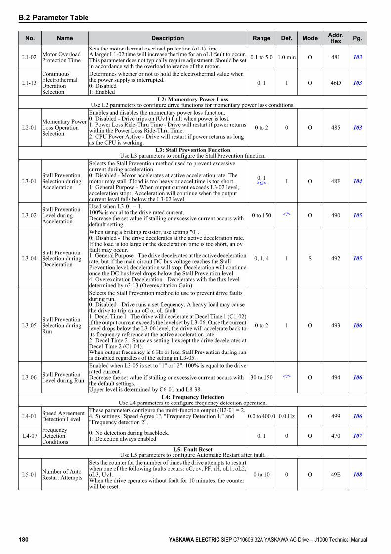
No. Name Description Range Def. Mode Addr.Hex Pg.
L1-02 Motor OverloadProtection Time
Sets the motor thermal overload protection (oL1) time.A larger L1-02 time will increase the time for an oL1 fault to occur.This parameter does not typically require adjustment. Should be setin accordance with the overload tolerance of the motor.
0.1 to 5.0 1.0 min O 481 103
L1-13 ContinuousElectrothermalOperationSelection
Determines whether or not to hold the electrothermal value whenthe power supply is interrupted.0: Disabled1: Enabled
0, 1 1 O 46D 103
L2: Momentary Power LossUse L2 parameters to configure drive functions for momentary power loss conditions.
L2-01 Momentary PowerLoss OperationSelection
Enables and disables the momentary power loss function.0: Disabled - Drive trips on (Uv1) fault when power is lost.1: Power Loss Ride-Thru Time - Drive will restart if power returnswithin the Power Loss Ride-Thru Time.2: CPU Power Active - Drive will restart if power returns as longas the CPU is working.
0 to 2 0 O 485 103
L3: Stall Prevention FunctionUse L3 parameters to configure the Stall Prevention function.
L3-01 Stall PreventionSelection duringAcceleration
Selects the Stall Prevention method used to prevent excessivecurrent during acceleration.0: Disabled - Motor accelerates at active acceleration rate. Themotor may stall if load is too heavy or accel time is too short.1: General Purpose - When output current exceeds L3-02 level,acceleration stops. Acceleration will continue when the outputcurrent level falls below the L3-02 level.
0, 1<63> 1 O 48F 104
L3-02 Stall PreventionLevel duringAcceleration
Used when L3-01 = 1.100% is equal to the drive rated current.Decrease the set value if stalling or excessive current occurs withdefault setting.
0 to 150 <7> O 490 105
L3-04 Stall PreventionSelection duringDeceleration
When using a braking resistor, use setting "0".0: Disabled - The drive decelerates at the active deceleration rate.If the load is too large or the deceleration time is too short, an ovfault may occur.1: General Purpose - The drive decelerates at the active decelerationrate, but if the main circuit DC bus voltage reaches the StallPrevention level, deceleration will stop. Deceleration will continueonce the DC bus level drops below the Stall Prevention level.4: Overexcitation Deceleration - Decelerates with the flux leveldetermined by n3-13 (Overexcitation Gain).
0, 1, 4 1 S 492 105
L3-05 Stall PreventionSelection duringRun
Selects the Stall Prevention method to use to prevent drive faultsduring run.0: Disabled - Drive runs a set frequency. A heavy load may causethe drive to trip on an oC or oL fault.1: Decel Time 1 - The drive will decelerate at Decel Time 1 (C1-02)if the output current exceeds the level set by L3-06. Once the currentlevel drops below the L3-06 level, the drive will accelerate back toits frequency reference at the active acceleration rate.2: Decel Time 2 - Same as setting 1 except the drive decelerates atDecel Time 2 (C1-04).When output frequency is 6 Hz or less, Stall Prevention during runis disabled regardless of the setting in L3-05.
0 to 2 1 O 493 106
L3-06 Stall PreventionLevel during Run
Enabled when L3-05 is set to "1" or "2". 100% is equal to the driverated current.Decrease the set value if stalling or excessive current occurs withthe default settings.Upper level is determined by C6-01 and L8-38.
30 to 150 <7> O 494 106
L4: Frequency DetectionUse L4 parameters to configure frequency detection operation.
L4-01 Speed AgreementDetection Level
These parameters configure the multi-function output (H2-01 = 2,4, 5) settings "Speed Agree 1", "Frequency Detection 1," and"Frequency detection 2".
0.0 to 400.0 0.0 Hz O 499 106
L4-07FrequencyDetectionConditions
0: No detection during baseblock.1: Detection always enabled. 0, 1 0 O 470 107
L5: Fault ResetUse L5 parameters to configure Automatic Restart after fault.
L5-01 Number of AutoRestart Attempts
Sets the counter for the number of times the drive attempts to restartwhen one of the following faults occurs: oC, ov, PF, rH, oL1, oL2,oL3, Uv1.When the drive operates without fault for 10 minutes, the counterwill be reset.
0 to 10 0 O 49E 108
B.2 Parameter Table
180 YASKAWA ELECTRIC SIEP C710606 32A YASKAWA AC Drive – J1000 Technical Manual
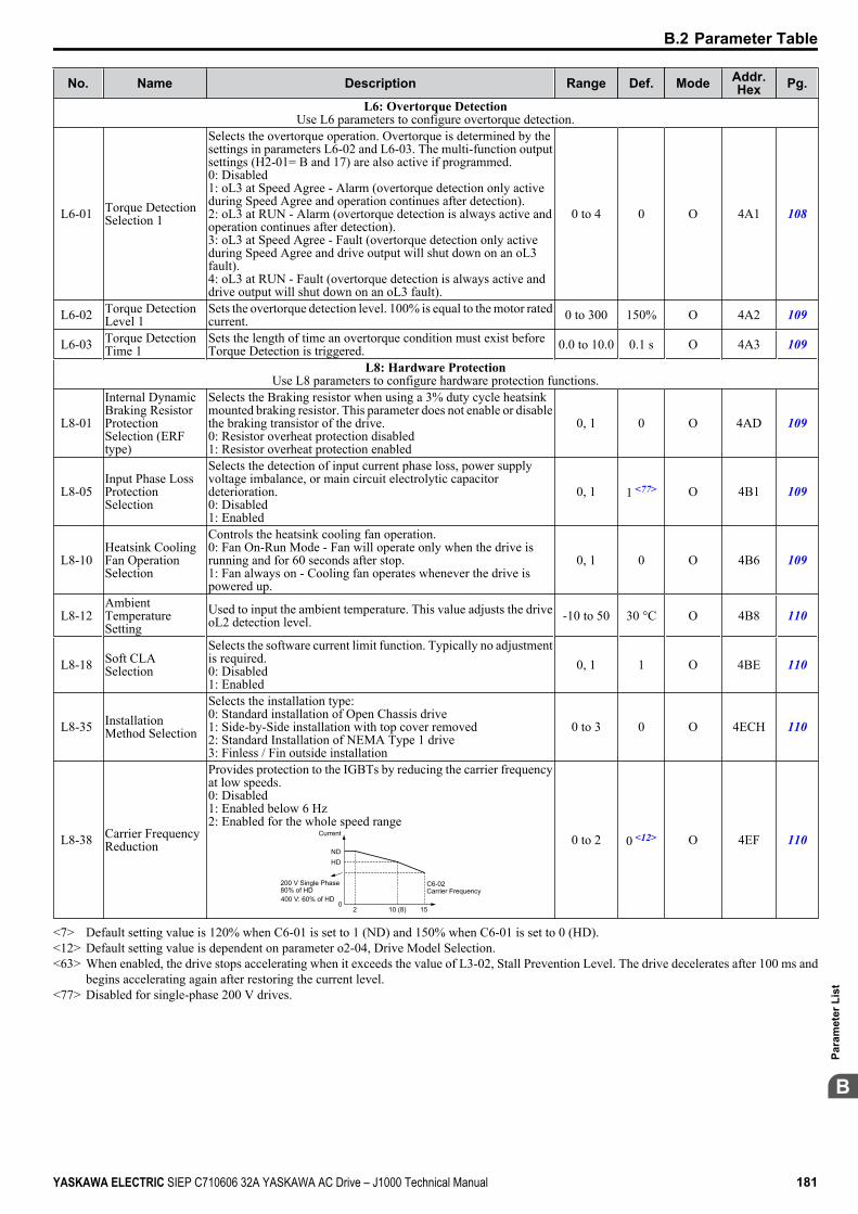
No. Name Description Range Def. Mode Addr.Hex Pg.
L6: Overtorque DetectionUse L6 parameters to configure overtorque detection.
L6-01 Torque DetectionSelection 1
Selects the overtorque operation. Overtorque is determined by thesettings in parameters L6-02 and L6-03. The multi-function outputsettings (H2-01= B and 17) are also active if programmed.0: Disabled1: oL3 at Speed Agree - Alarm (overtorque detection only activeduring Speed Agree and operation continues after detection).2: oL3 at RUN - Alarm (overtorque detection is always active andoperation continues after detection).3: oL3 at Speed Agree - Fault (overtorque detection only activeduring Speed Agree and drive output will shut down on an oL3fault).4: oL3 at RUN - Fault (overtorque detection is always active anddrive output will shut down on an oL3 fault).
0 to 4 0 O 4A1 108
L6-02 Torque DetectionLevel 1
Sets the overtorque detection level. 100% is equal to the motor ratedcurrent. 0 to 300 150% O 4A2 109
L6-03 Torque DetectionTime 1
Sets the length of time an overtorque condition must exist beforeTorque Detection is triggered. 0.0 to 10.0 0.1 s O 4A3 109
L8: Hardware ProtectionUse L8 parameters to configure hardware protection functions.
L8-01
Internal DynamicBraking ResistorProtectionSelection (ERFtype)
Selects the Braking resistor when using a 3% duty cycle heatsinkmounted braking resistor. This parameter does not enable or disablethe braking transistor of the drive.0: Resistor overheat protection disabled1: Resistor overheat protection enabled
0, 1 0 O 4AD 109
L8-05 Input Phase LossProtectionSelection
Selects the detection of input current phase loss, power supplyvoltage imbalance, or main circuit electrolytic capacitordeterioration.0: Disabled1: Enabled
0, 1 1 <77> O 4B1 109
L8-10 Heatsink CoolingFan OperationSelection
Controls the heatsink cooling fan operation.0: Fan On-Run Mode - Fan will operate only when the drive isrunning and for 60 seconds after stop.1: Fan always on - Cooling fan operates whenever the drive ispowered up.
0, 1 0 O 4B6 109
L8-12 AmbientTemperatureSetting
Used to input the ambient temperature. This value adjusts the driveoL2 detection level. -10 to 50 30 °C O 4B8 110
L8-18 Soft CLASelection
Selects the software current limit function. Typically no adjustmentis required.0: Disabled1: Enabled
0, 1 1 O 4BE 110
L8-35 InstallationMethod Selection
Selects the installation type:0: Standard installation of Open Chassis drive1: Side-by-Side installation with top cover removed2: Standard Installation of NEMA Type 1 drive3: Finless / Fin outside installation
0 to 3 0 O 4ECH 110
L8-38 Carrier FrequencyReduction
Provides protection to the IGBTs by reducing the carrier frequencyat low speeds.0: Disabled1: Enabled below 6 Hz2: Enabled for the whole speed range
Current
C6-02Carrier Frequency
NDHD
20
200 V Single Phase80% of HD
10 (8) 15400 V: 60% of HD
0 to 2 0 <12> O 4EF 110
<7> Default setting value is 120% when C6-01 is set to 1 (ND) and 150% when C6-01 is set to 0 (HD).<12> Default setting value is dependent on parameter o2-04, Drive Model Selection.<63> When enabled, the drive stops accelerating when it exceeds the value of L3-02, Stall Prevention Level. The drive decelerates after 100 ms and
begins accelerating again after restoring the current level.<77> Disabled for single-phase 200 V drives.
B.2 Parameter Table
YASKAWA ELECTRIC SIEP C710606 32A YASKAWA AC Drive – J1000 Technical Manual 181
B
Para
met
er L
ist

u n: Advanced Performance Set-UpThe n parameters are used to adjust more advanced performance characteristics.
No. Name Description Range Def. Mode Addr.Hex Pg.
n1: Hunting PreventionUse n1 parameters to configure hunting prevention operation.
n1-02 HuntingPrevention GainSetting
Sets the gain for the Hunting Prevention Function.If the motor vibrates while lightly loaded, increase the gain by 0.1until vibration ceases.If the motor stalls, decrease the gain by 0.1 until the stalling ceases.
0.00 to 2.50 1.00 O 581 112
n3: Overexcitation BrakingUse n3 parameters to configure the overexcitation braking function.
n3-13 OverexcitationDeceleration Gain
Applies a gain to the V/f pattern during deceleration (L3-04 = 4).Returns to normal values after ramp to stop or at re-acceleration.To increase the braking power of overexcitation, increase the gainby 1.25 to 1.30.
1.00 to 1.40 1.10 O 531 112
u o: Operator Related Parameterso parameters are used to set up the LED digital operator displays.
No. Name Description Range Def. Mode Addr.Hex Pg.
o1: Display SettingsUse o1 parameters to configure the digital operator display.
o1-02<22>
User MonitorSelection AfterPower Up
Selects the monitor to display upon power-up.1: Frequency Reference (U1-01)2: Forward/Reverse3: Output Frequency (U1-02)4: Output Current (U1-03)
1 to 4 1 O 501 113
o1-03 Digital OperatorDisplay Selection
Sets the units to display the frequency reference and outputfrequency.0: 0.01 Hz1: 0.01% (100% = E1-04)
0, 1 0 O 502 113
o2: Operator Keypad FunctionsUse o2 parameters to configure LED digital operator key functions.
o2-02 STOP KeyFunction Selection
Determines if the STOP key on the digital operator will stop thedrive when operating from the external terminals or via serialcommunication.0: Disabled1: Enabled
0, 1 1 O 506 113
o2-04 Drive ModelSelection
Sets the drive model.This parameter only needs to be set when installing a new controlboard. Do not change for other reason.
0 to FFdep. ondrivespec.
O 508 113
o2-05 FrequencyReference SettingMethod Selection
Selects if the ENTER key must be pressed when inputting thefrequency reference by the operator keypad.0: Data/Enter key must be pressed to enter a frequency reference.1: Data/Enter key is not required. The frequency reference isadjusted by the UP and DOWN keys.
0, 1 0 O 509 114
o2-06OperationSelection whenDigital Operator isDisconnected
Sets drive action when the digital operator is removed in LOCALmode or with b1-02 = 0 (valid for optional remote operator only).0: The drive will continue operation1: The drive will trigger a fault (oPr) and the motor will coast to stop
0, 1 0 O 50A 114
o2-09 Initialization mode (Maker setting) 0 to 3dep. ondrivespec.
O 50D 114
o3: Copy FunctionUse o3 parameters to Read, Copy and Verify the parameter settings to and from the drive.
o3-01 Copy FunctionSelection
Selects the copy function operation.0: No action1: READ - All parameters are read from the drive and stored in theLED operator.2: COPY - All parameters are copied from the LED operator to thedrive.3: VERIFY - Parameter settings in the drive are compared to thosein the LED operator.NOTE: When using the copy function, the drive model number(o2-04) and the software number (U1-14) must match or an errorwill occur.
0 to 3 0 O 515 114
o3-02 Copy FunctionREAD Permission
Locks the READ operation to prevent accidental overwriting of thedata stored in the LED operator.0: READ operation prohibited1: READ operation allowed
0, 1 0 O 516 114
B.2 Parameter Table
182 YASKAWA ELECTRIC SIEP C710606 32A YASKAWA AC Drive – J1000 Technical Manual
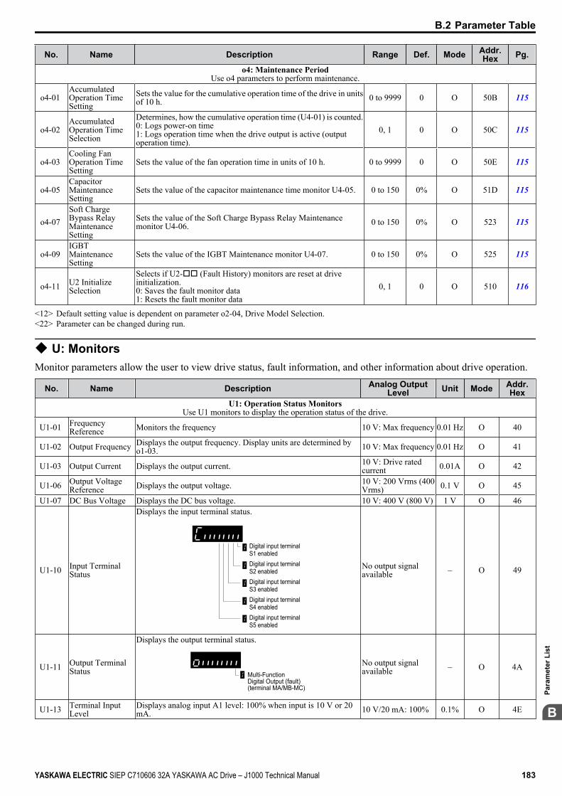
No. Name Description Range Def. Mode Addr.Hex Pg.
o4: Maintenance PeriodUse o4 parameters to perform maintenance.
o4-01 AccumulatedOperation TimeSetting
Sets the value for the cumulative operation time of the drive in unitsof 10 h. 0 to 9999 0 O 50B 115
o4-02 AccumulatedOperation TimeSelection
Determines, how the cumulative operation time (U4-01) is counted.0: Logs power-on time1: Logs operation time when the drive output is active (outputoperation time).
0, 1 0 O 50C 115
o4-03 Cooling FanOperation TimeSetting
Sets the value of the fan operation time in units of 10 h. 0 to 9999 0 O 50E 115
o4-05 CapacitorMaintenanceSetting
Sets the value of the capacitor maintenance time monitor U4-05. 0 to 150 0% O 51D 115
o4-07 Soft ChargeBypass RelayMaintenanceSetting
Sets the value of the Soft Charge Bypass Relay Maintenancemonitor U4-06. 0 to 150 0% O 523 115
o4-09 IGBTMaintenanceSetting
Sets the value of the IGBT Maintenance monitor U4-07. 0 to 150 0% O 525 115
o4-11 U2 InitializeSelection
Selects if U2-oo (Fault History) monitors are reset at driveinitialization.0: Saves the fault monitor data1: Resets the fault monitor data
0, 1 0 O 510 116
<12> Default setting value is dependent on parameter o2-04, Drive Model Selection.<22> Parameter can be changed during run.
u U: MonitorsMonitor parameters allow the user to view drive status, fault information, and other information about drive operation.
No. Name Description Analog OutputLevel Unit Mode Addr.
HexU1: Operation Status Monitors
Use U1 monitors to display the operation status of the drive.
U1-01 FrequencyReference Monitors the frequency 10 V: Max frequency 0.01 Hz O 40
U1-02 Output Frequency Displays the output frequency. Display units are determined byo1-03. 10 V: Max frequency 0.01 Hz O 41
U1-03 Output Current Displays the output current. 10 V: Drive ratedcurrent 0.01A O 42
U1-06 Output VoltageReference Displays the output voltage. 10 V: 200 Vrms (400
Vrms) 0.1 V O 45
U1-07 DC Bus Voltage Displays the DC bus voltage. 10 V: 400 V (800 V) 1 V O 46
U1-10 Input TerminalStatus
Displays the input terminal status.
Digital input terminal S1 enabledDigital input terminal S2 enabledDigital input terminal S3 enabledDigital input terminal S4 enabledDigital input terminal S5 enabled
No output signalavailable – O 49
U1-11 Output TerminalStatus
Displays the output terminal status.
Multi-Function Digital Output (fault) (terminal MA/MB-MC)
No output signalavailable – O 4A
U1-13 Terminal InputLevel
Displays analog input A1 level: 100% when input is 10 V or 20mA. 10 V/20 mA: 100% 0.1% O 4E
B.2 Parameter Table
YASKAWA ELECTRIC SIEP C710606 32A YASKAWA AC Drive – J1000 Technical Manual 183
B
Para
met
er L
ist
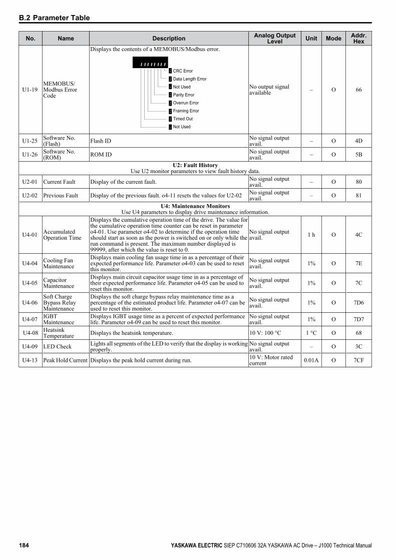
No. Name Description Analog OutputLevel Unit Mode Addr.
Hex
U1-19 MEMOBUS/Modbus ErrorCode
Displays the contents of a MEMOBUS/Modbus error.
CRC Error
Data Length Error
Not Used
Parity Error
Overrun Error
Framing Error
Timed Out
Not Used
No output signalavailable – O 66
U1-25 Software No.(Flash) Flash ID No signal output
avail. – O 4D
U1-26 Software No.(ROM) ROM ID No signal output
avail. – O 5B
U2: Fault HistoryUse U2 monitor parameters to view fault history data.
U2-01 Current Fault Display of the current fault. No signal outputavail. – O 80
U2-02 Previous Fault Display of the previous fault. o4-11 resets the values for U2-02 No signal outputavail. – O 81
U4: Maintenance MonitorsUse U4 parameters to display drive maintenance information.
U4-01 AccumulatedOperation Time
Displays the cumulative operation time of the drive. The value forthe cumulative operation time counter can be reset in parametero4-01. Use parameter o4-02 to determine if the operation timeshould start as soon as the power is switched on or only while therun command is present. The maximum number displayed is99999, after which the value is reset to 0.
No signal outputavail. 1 h O 4C
U4-04 Cooling FanMaintenance
Displays main cooling fan usage time in as a percentage of theirexpected performance life. Parameter o4-03 can be used to resetthis monitor.
No signal outputavail. 1% O 7E
U4-05 CapacitorMaintenance
Displays main circuit capacitor usage time in as a percentage oftheir expected performance life. Parameter o4-05 can be used toreset this monitor.
No signal outputavail. 1% O 7C
U4-06 Soft ChargeBypass RelayMaintenance
Displays the soft charge bypass relay maintenance time as apercentage of the estimated product life. Parameter o4-07 can beused to reset this monitor.
No signal outputavail. 1% O 7D6
U4-07 IGBTMaintenance
Displays IGBT usage time as a percent of expected performancelife. Parameter o4-09 can be used to reset this monitor.
No signal outputavail. 1% O 7D7
U4-08 HeatsinkTemperature Displays the heatsink temperature. 10 V: 100 °C 1 °C O 68
U4-09 LED Check Lights all segments of the LED to verify that the display is workingproperly.
No signal outputavail. – O 3C
U4-13 Peak Hold Current Displays the peak hold current during run. 10 V: Motor ratedcurrent 0.01A O 7CF
B.2 Parameter Table
184 YASKAWA ELECTRIC SIEP C710606 32A YASKAWA AC Drive – J1000 Technical Manual
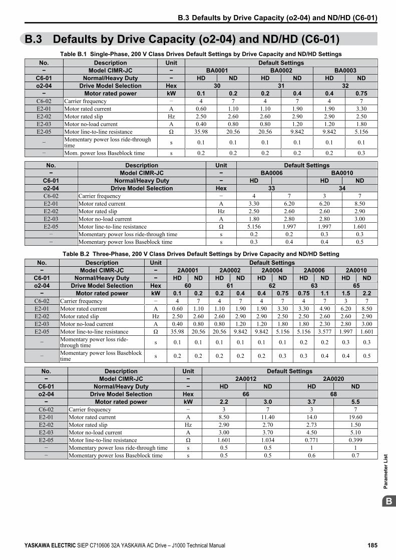
B.3 Defaults by Drive Capacity (o2-04) and ND/HD (C6-01)Table B.1 Single-Phase, 200 V Class Drives Default Settings by Drive Capacity and ND/HD Settings
No. Description Unit Default Settings− Model CIMR-JC − BA0001 BA0002 BA0003
C6-01 Normal/Heavy Duty − HD ND HD ND HD NDo2-04 Drive Model Selection Hex 30 31 32
− Motor rated power kW 0.1 0.2 0.2 0.4 0.4 0.75C6-02 Carrier frequency − 4 7 4 7 4 7E2-01 Motor rated current A 0.60 1.10 1.10 1.90 1.90 3.30E2-02 Motor rated slip Hz 2.50 2.60 2.60 2.90 2.90 2.50E2-03 Motor no-load current A 0.40 0.80 0.80 1.20 1.20 1.80E2-05 Motor line-to-line resistance Ω 35.98 20.56 20.56 9.842 9.842 5.156
− Momentary power loss ride-throughtime s 0.1 0.1 0.1 0.1 0.1 0.1
− Mom. power loss Baseblock time s 0.2 0.2 0.2 0.2 0.2 0.3
No. Description Unit Default Settings− Model CIMR-JC − BA0006 BA0010
C6-01 Normal/Heavy Duty − HD HD NDo2-04 Drive Model Selection Hex 33 34C6-02 Carrier frequency − 4 7 3 7E2-01 Motor rated current A 3.30 6.20 6.20 8.50E2-02 Motor rated slip Hz 2.50 2.60 2.60 2.90E2-03 Motor no-load current A 1.80 2.80 2.80 3.00E2-05 Motor line-to-line resistance Ω 5.156 1.997 1.997 1.601
− Momentary power loss ride-through time s 0.2 0.2 0.3 0.3− Momentary power loss Baseblock time s 0.3 0.4 0.4 0.5
Table B.2 Three-Phase, 200 V Class Drives Default Settings by Drive Capacity and ND/HD SettingNo. Description Unit Default Settings− Model CIMR-JC − 2A0001 2A0002 2A0004 2A0006 2A0010
C6-01 Normal/Heavy Duty − HD ND HD ND HD ND HD ND HD NDo2-04 Drive Model Selection Hex 60 61 62 63 65
− Motor rated power kW 0.1 0.2 0.2 0.4 0.4 0.75 0.75 1.1 1.5 2.2C6-02 Carrier frequency − 4 7 4 7 4 7 4 7 3 7E2-01 Motor rated current A 0.60 1.10 1.10 1.90 1.90 3.30 3.30 4.90 6.20 8.50E2-02 Motor rated slip Hz 2.50 2.60 2.60 2.90 2.90 2.50 2.50 2.60 2.60 2.90E2-03 Motor no-load current A 0.40 0.80 0.80 1.20 1.20 1.80 1.80 2.30 2.80 3.00E2-05 Motor line-to-line resistance Ω 35.98 20.56 20.56 9.842 9.842 5.156 5.156 3.577 1.997 1.601
− Momentary power loss ride-through time s 0.1 0.1 0.1 0.1 0.1 0.1 0.2 0.2 0.3 0.3
− Momentary power loss Baseblocktime s 0.2 0.2 0.2 0.2 0.2 0.3 0.3 0.4 0.4 0.5
No. Description Unit Default Settings− Model CIMR-JC − 2A0012 2A0020
C6-01 Normal/Heavy Duty − HD ND HD NDo2-04 Drive Model Selection Hex 66 68
− Motor rated power kW 2.2 3.0 3.7 5.5C6-02 Carrier frequency − 3 7 3 7E2-01 Motor rated current A 8.50 11.40 14.0 19.60E2-02 Motor rated slip Hz 2.90 2.70 2.73 1.50E2-03 Motor no-load current A 3.00 3.70 4.50 5.10E2-05 Motor line-to-line resistance Ω 1.601 1.034 0.771 0.399
− Momentary power loss ride-through time s 0.5 0.5 1 1− Momentary power loss Baseblock time s 0.5 0.5 0.6 0.7
B.3 Defaults by Drive Capacity (o2-04) and ND/HD (C6-01)
YASKAWA ELECTRIC SIEP C710606 32A YASKAWA AC Drive – J1000 Technical Manual 185
B
Para
met
er L
ist

Table B.3 Three-Phase 400 V Class Drives Default Settings by Drive Capacity and ND/HD SettingNo. Description Unit Default Settings− Model CIMR-JC − 4A0001 4A0002 4A0004 4A0005
C6-01 Normal/Heavy Duty − HD ND HD ND HD ND HD NDo2-04 Drive Model Selection Hex 91 92 93 94
− Motor rated power kW 0.2 0.4 0.4 0.75 0.75 1.5 1.5 2.2C6-02 Carrier frequency − 3 7 3 7 3 7 3 7E2-01 Motor rated current A 0.60 1.00 1.00 1.60 1.60 3.10 3.10 4.20E2-02 Motor rated slip Hz 2.50 2.90 2.90 2.60 2.60 2.50 2.50 3.00E2-03 Motor no-load current A 0.40 0.60 0.60 0.80 0.80 1.40 1.40 1.50E2-05 Motor line-to-line resistance Ω 83.94 38.198 38.198 22.459 22.459 10.1 10.1 6.495
− Momentary power loss ride-through time s 0.1 0.1 0.1 0.1 0.2 0.2 0.3 0.3
− Momentary power loss Baseblocktime s 0.2 0.2 0.2 0.3 0.3 0.4 0.4 0.5
No. Description Unit Default Setting− Model CIMR-JC − 4A0007 4A0009 4A0011
C6-01 Normal/Heavy Duty − HD ND HD ND HD NDo2-04 Drive Model Selection − 95 96 97
− Motor rated power kW 2.2 3.0 3.0 3.7 4.0 5.5C6-02 Carrier frequency − 3 7 3 7 3 7E2-01 Motor rated current A 4.20 5.70 5.70 7.00 7.00 9.80E2-02 Motor rated slip Hz 3.00 2.70 2.70 2.70 2.70 1.50E2-03 Motor no-load current A 1.50 1.90 1.90 2.30 2.30 2.60E2-05 Motor line-to-line resistance Ω 6.495 4.360 4.360 3.333 3.333 1.595
− Momentary power loss ride-through time s 0.5 0.5 0.5 0.5 0.5 0.5− Momentary power loss Baseblock time s 0.5 0.5 0.5 0.6 0.6 0.7
B.3 Defaults by Drive Capacity (o2-04) and ND/HD (C6-01)
186 YASKAWA ELECTRIC SIEP C710606 32A YASKAWA AC Drive – J1000 Technical Manual
MEMOBUS/Modbus Communications
C.1 SECTION SAFETY..........................................................................................188C.2 MEMOBUS/MODBUS CONFIGURATION......................................................189C.3 COMMUNICATION SPECIFICATIONS..........................................................190C.4 CONNECTING TO A NETWORK....................................................................191C.5 MEMOBUS/MODBUS SETUP PARAMETERS..............................................193C.6 DRIVE OPERATIONS BY MEMOBUS/MODBUS..........................................195C.7 COMMUNICATIONS TIMING..........................................................................196C.8 MESSAGE FORMAT.......................................................................................197C.9 MESSAGE EXAMPLES..................................................................................199C.10 MEMOBUS/MODBUS DATA TABLE.............................................................201C.11 CHANGING DRIVE PARAMETERS...............................................................207C.12 COMMUNICATION ERRORS.........................................................................208C.13 SELF-DIAGNOSTICS......................................................................................209
Appendix: C
YASKAWA ELECTRIC SIEP C710606 32A YASKAWA AC Drive – J1000 Technical Manual 187
C.1 Section Safety DANGER
Electrical Shock HazardDo not connect or disconnect wiring while the power is on.Failure to comply will result in death or serious injury.Before servicing, disconnect all power to the equipment. The internal capacitor remains charged even after the powersupply is turned off. The charge indicator LED will extinguish when the DC bus voltage is below 50 Vdc. To preventelectric shock, wait at least one minute after all indicators are OFF and measure the DC bus voltage level to confirm safelevel.
WARNINGDo not operate equipment with covers removed.Failure to comply could result in death or serious injury.Do not perform work on the drive while wearing loose clothing, jewelry or without eye protection.Failure to comply could result in death or serious injury.Remove all metal objects such as watches and rings, secure loose clothing and wear eye protection before beginningwork on the drive.Do not remove covers or touch circuit boards while the power is on.Failure to comply could result in death or serious injury.Do not allow unqualified personnel to use equipment.Failure to comply could result in death or serious injury.Maintenance, inspection and replacement of parts must be performed only by authorized personnel familiar withinstallation, adjustment and maintenance of AC drives.Before wiring terminals, disconnect all power to the equipment.The internal capacitor remains charged even after the power supply is turned off. The charge indicator LED will extinguishwhen the DC bus voltage is below 50 Vdc. To prevent electric shock, wait at least one minute after all indicators are OFFand measure the DC bus voltage level to confirm safe level.
Fire HazardTighten all terminal screws to the specified tightening torque.Loose electrical connections could result in death or serious injury by fire due to overheating of electrical connections.
CAUTIONCrush Hazard
Do not carry the drive by the front cover.Failure to comply may result in minor or moderate injury from the main body of the drive falling.
NOTICEObserve proper electrostatic discharge procedures (ESD) when handling the drive and circuit boards.Failure to comply may result in ESD damage to the drive circuitry.Check all the wiring to ensure that all connections are correct after installing the drive and connecting any otherdevices.Failure to comply could result in damage to the drive.
C.1 Section Safety
188 YASKAWA ELECTRIC SIEP C710606 32A YASKAWA AC Drive – J1000 Technical Manual
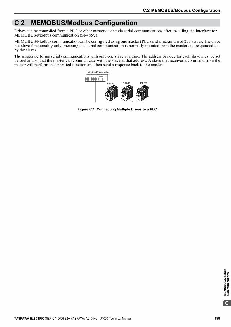
C.2 MEMOBUS/Modbus ConfigurationDrives can be controlled from a PLC or other master device via serial communications after installing the interface forMEMOBUS/Modbus communication (SI-485/J).MEMOBUS/Modbus communication can be configured using one master (PLC) and a maximum of 255 slaves. The drivehas slave functionality only, meaning that serial communication is normally initiated from the master and responded toby the slaves.The master performs serial communications with only one slave at a time. The address or node for each slave must be setbeforehand so that the master can communicate with the slave at that address. A slave that receives a command from themaster will perform the specified function and then send a response back to the master.
Master (PLC or other)
DRIVE DRIVE DRIVE
Figure C.1 Connecting Multiple Drives to a PLC
C.2 MEMOBUS/Modbus Configuration
YASKAWA ELECTRIC SIEP C710606 32A YASKAWA AC Drive – J1000 Technical Manual 189
C
MEM
OB
US/
Mod
bus
Com
mun
icat
ions
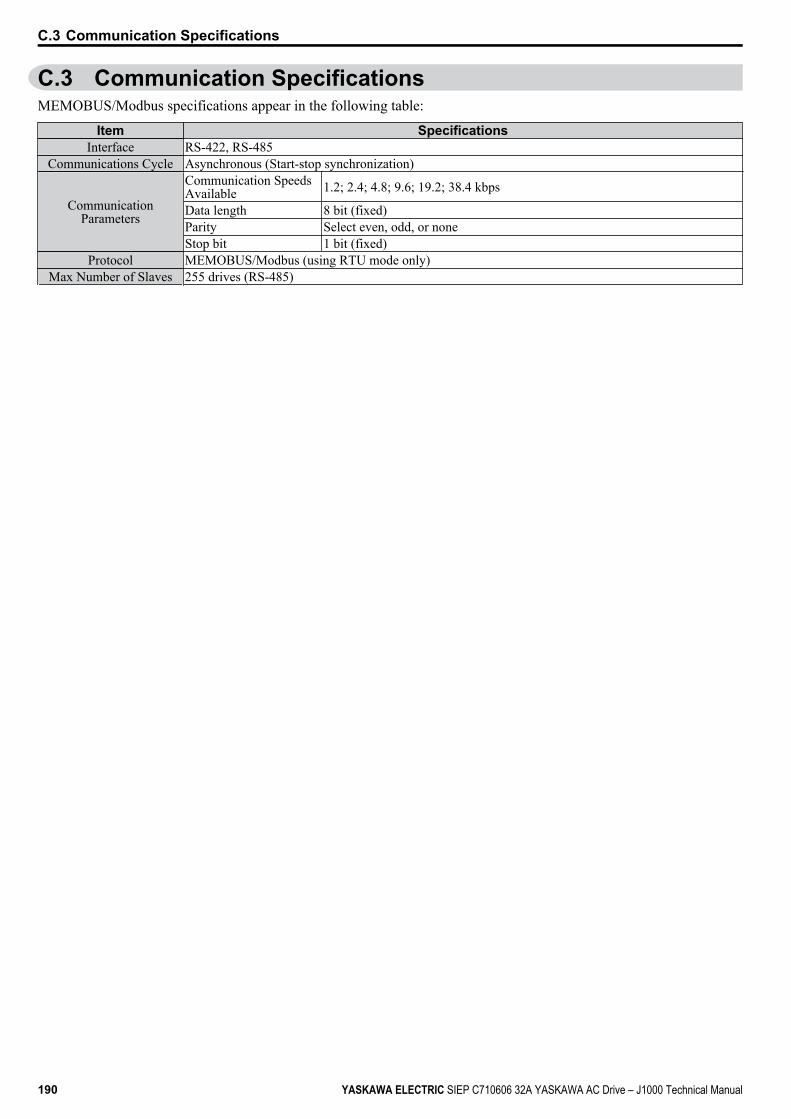
C.3 Communication SpecificationsMEMOBUS/Modbus specifications appear in the following table:
Item SpecificationsInterface RS-422, RS-485
Communications Cycle Asynchronous (Start-stop synchronization)
CommunicationParameters
Communication SpeedsAvailable 1.2; 2.4; 4.8; 9.6; 19.2; 38.4 kbps
Data length 8 bit (fixed)Parity Select even, odd, or noneStop bit 1 bit (fixed)
Protocol MEMOBUS/Modbus (using RTU mode only)Max Number of Slaves 255 drives (RS-485)
C.3 Communication Specifications
190 YASKAWA ELECTRIC SIEP C710606 32A YASKAWA AC Drive – J1000 Technical Manual
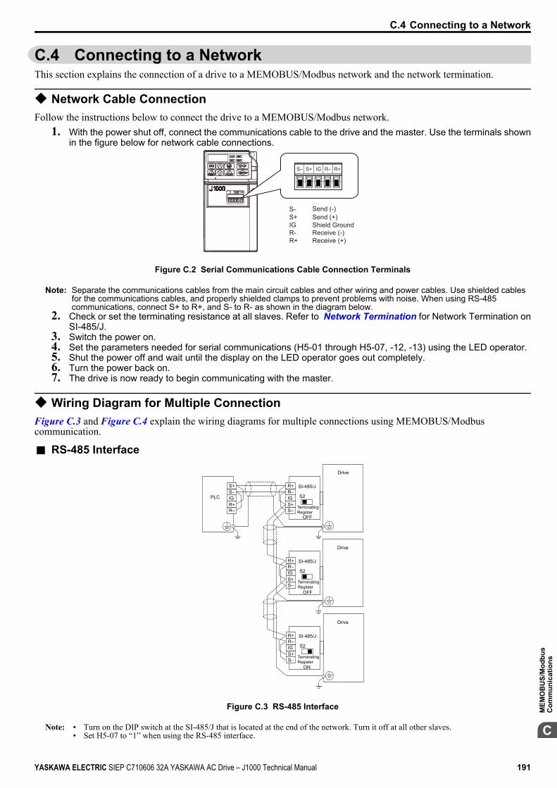
C.4 Connecting to a NetworkThis section explains the connection of a drive to a MEMOBUS/Modbus network and the network termination.
u Network Cable ConnectionFollow the instructions below to connect the drive to a MEMOBUS/Modbus network.
1. With the power shut off, connect the communications cable to the drive and the master. Use the terminals shownin the figure below for network cable connections.
S– S+ IG R– R+
S-S+IGR- R+
Send (-)
Receive (+)Receive (-)Shield GroundSend (+)
Figure C.2 Serial Communications Cable Connection Terminals
Note: Separate the communications cables from the main circuit cables and other wiring and power cables. Use shielded cablesfor the communications cables, and properly shielded clamps to prevent problems with noise. When using RS-485communications, connect S+ to R+, and S- to R- as shown in the diagram below.
2. Check or set the terminating resistance at all slaves. Refer to Network Termination for Network Termination onSI-485/J.
3. Switch the power on.4. Set the parameters needed for serial communications (H5-01 through H5-07, -12, -13) using the LED operator.5. Shut the power off and wait until the display on the LED operator goes out completely.6. Turn the power back on.7. The drive is now ready to begin communicating with the master.
u Wiring Diagram for Multiple ConnectionFigure C.3 and Figure C.4 explain the wiring diagrams for multiple connections using MEMOBUS/Modbuscommunication.
n RS-485 Interface
SI-485/J
OFF
S2
R+R–IGS+S–
SI-485/J
OFF
S2
R+R–IGS+S–
SI-485/J
ON
S2
R+R–IGS+S–
S+S–IGR+R–
PLC
Drive
Drive
Drive
TerminatingRegister
TerminatingRegister
TerminatingRegister
Figure C.3 RS-485 Interface
Note: • Turn on the DIP switch at the SI-485/J that is located at the end of the network. Turn it off at all other slaves.• Set H5-07 to “1” when using the RS-485 interface.
C.4 Connecting to a Network
YASKAWA ELECTRIC SIEP C710606 32A YASKAWA AC Drive – J1000 Technical Manual 191
C
MEM
OB
US/
Mod
bus
Com
mun
icat
ions
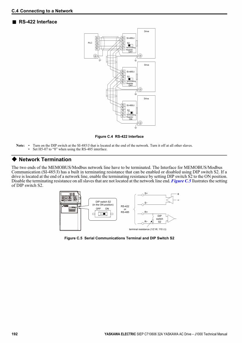
n RS-422 Interface
S+S–IGR+R–
PLC
SI-485/J
OFF
S2
R+R–IGS+S–
SI-485/J
OFF
S2
R+R–IGS+S–
SI-485/J
ON
S2
R+R–IGS+S–
Drive
Drive
Drive
TerminatingRegister
TerminatingRegister
TerminatingRegister
Figure C.4 RS-422 Interface
Note: • Turn on the DIP switch at the SI-485/J that is located at the end of the network. Turn it off at all other slaves.• Set H5-07 to “0” when using the RS-485 interface.
u Network TerminationThe two ends of the MEMOBUS/Modbus network line have to be terminated. The Interface for MEMOBUS/ModbusCommunication (SI-485/J) has a built in terminating resistance that can be enabled or disabled using DIP switch S2. If adrive is located at the end of a network line, enable the terminating resistance by setting DIP switch S2 to the ON position.Disable the terminating resistance on all slaves that are not located at the network line end. Figure C.5 llustrates the settingof DIP switch S2.
R+
R-
S+
S-
+-
RS-422or
RS-485DIP
switchS2
terminal resistance (1/2 W, 110 )
DIP switch S2(in the ON position)
OFF ON
Figure C.5 Serial Communications Terminal and DIP Switch S2
C.4 Connecting to a Network
192 YASKAWA ELECTRIC SIEP C710606 32A YASKAWA AC Drive – J1000 Technical Manual
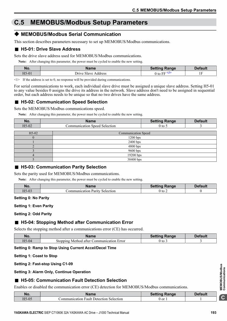
C.5 MEMOBUS/Modbus Setup Parameters
u MEMOBUS/Modbus Serial CommunicationThis section describes parameters necessary to set up MEMOBUS/Modbus communications.
n H5-01: Drive Slave AddressSets the drive slave address used for MEMOBUS/Modbus communications.
Note: After changing this parameter, the power must be cycled to enable the new setting.
No. Name Setting Range DefaultH5-01 Drive Slave Address 0 to FF <1> 1F
<1> If the address is set to 0, no response will be provided during communications.
For serial communications to work, each individual slave drive must be assigned a unique slave address. Setting H5-01to any value besides 0 assigns the drive its address in the network. Slave address don't need to be assigned in sequentialorder, but each address needs to be unique so that no two drives have the same address.
n H5-02: Communication Speed SelectionSets the MEMOBUS/Modbus communications speed.
Note: After changing this parameter, the power must be cycled to enable the new setting.
No. Name Setting Range DefaultH5-02 Communication Speed Selection 0 to 5 3
H5-02 Communication Speed0 1200 bps1 2400 bps2 4800 bps3 9600 bps4 19200 bps5 38400 bps
n H5-03: Communication Parity SelectionSets the parity used for MEMOBUS/Modbus communications.
Note: After changing this parameter, the power must be cycled to enable the new setting.
No. Name Setting Range DefaultH5-03 Communication Parity Selection 0 to 2 0
Setting 0: No Parity
Setting 1: Even Parity
Setting 2: Odd Parity
n H5-04: Stopping Method after Communication ErrorSelects the stopping method after a communications error (CE) has occurred.
No. Name Setting Range DefaultH5-04 Stopping Method after Communication Error 0 to 3 3
Setting 0: Ramp to Stop Using Current Accel/Decel Time
Setting 1: Coast to Stop
Setting 2: Fast-stop Using C1-09
Setting 3: Alarm Only, Continue Operation
n H5-05: Communication Fault Detection SelectionEnables or disabled the communication error (CE) detection for MEMOBUS/Modbus communications.
No. Name Setting Range DefaultH5-05 Communication Fault Detection Selection 0 or 1 1
C.5 MEMOBUS/Modbus Setup Parameters
YASKAWA ELECTRIC SIEP C710606 32A YASKAWA AC Drive – J1000 Technical Manual 193
C
MEM
OB
US/
Mod
bus
Com
mun
icat
ions
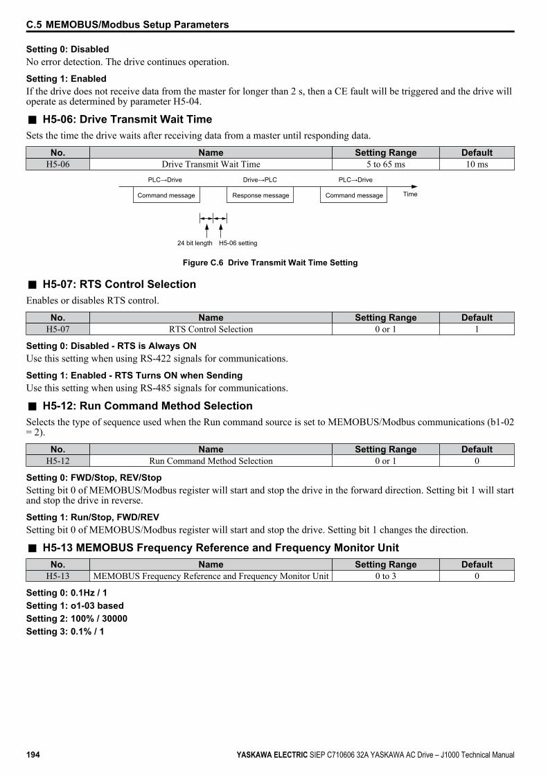
Setting 0: DisabledNo error detection. The drive continues operation.
Setting 1: EnabledIf the drive does not receive data from the master for longer than 2 s, then a CE fault will be triggered and the drive willoperate as determined by parameter H5-04.
n H5-06: Drive Transmit Wait TimeSets the time the drive waits after receiving data from a master until responding data.
No. Name Setting Range DefaultH5-06 Drive Transmit Wait Time 5 to 65 ms 10 ms
Command message Response message Command message
PLC→Drive PLC→DriveDrive→PLC
Time
24 bit length H5-06 setting
Figure C.6 Drive Transmit Wait Time Setting
n H5-07: RTS Control SelectionEnables or disables RTS control.
No. Name Setting Range DefaultH5-07 RTS Control Selection 0 or 1 1
Setting 0: Disabled - RTS is Always ONUse this setting when using RS-422 signals for communications.
Setting 1: Enabled - RTS Turns ON when SendingUse this setting when using RS-485 signals for communications.
n H5-12: Run Command Method SelectionSelects the type of sequence used when the Run command source is set to MEMOBUS/Modbus communications (b1-02= 2).
No. Name Setting Range DefaultH5-12 Run Command Method Selection 0 or 1 0
Setting 0: FWD/Stop, REV/StopSetting bit 0 of MEMOBUS/Modbus register will start and stop the drive in the forward direction. Setting bit 1 will startand stop the drive in reverse.
Setting 1: Run/Stop, FWD/REVSetting bit 0 of MEMOBUS/Modbus register will start and stop the drive. Setting bit 1 changes the direction.
n H5-13 MEMOBUS Frequency Reference and Frequency Monitor UnitNo. Name Setting Range Default
H5-13 MEMOBUS Frequency Reference and Frequency Monitor Unit 0 to 3 0
Setting 0: 0.1Hz / 1Setting 1: o1-03 basedSetting 2: 100% / 30000Setting 3: 0.1% / 1
C.5 MEMOBUS/Modbus Setup Parameters
194 YASKAWA ELECTRIC SIEP C710606 32A YASKAWA AC Drive – J1000 Technical Manual

C.6 Drive Operations by MEMOBUS/ModbusThe drive operations that can be performed by MEMOBUS/Modbus communication depend on drive parameter settings.This section explains the functions that can be used and related parameter settings.
u Observing the Drive OperationA PLC can perform the following actions with MEMOBUS/Modbus communications at any time regardless of parametersettings (except H5-oo).• Observe drive status and drive control terminal status from a PLC.• Read and write parameters.• Set and reset faults.• Set multi-function inputs. Inputs settings from the input terminals So and from MEMOBUS/Modbus communications
are both linked by an OR operation.
u Controlling the DriveTo start and stop the drive or set the frequency reference using MEMOBUS/Modbus communications, an external referencemust be selected and the parameters listed below must be adjusted accordingly.
Table C.1 Setting Parameters for Drive Control from MEMOBUS/ModbusParameter Name Required Setting
b1-01 Frequency Reference Selection 2b1-02 Run Command Selection 2
Refer to b1-01: Frequency Reference Selection on page 72 and Refer to b1-02: Run Command Selection on page 73for details on external reference parameter selections.
C.6 Drive Operations by MEMOBUS/Modbus
YASKAWA ELECTRIC SIEP C710606 32A YASKAWA AC Drive – J1000 Technical Manual 195
C
MEM
OB
US/
Mod
bus
Com
mun
icat
ions

C.7 Communications TimingTo prevent overrun in the slave drive, the master should wait a certain time between sending messages to the same drive.In the same way, the slave drive must wait before sending response messages to prevent an overrun in the master. Thissection explains the message timing.
u Command Messages from Master to DriveIn order to prevent overrun and data loss, the master must wait between receiving a response and sending the same typeof command as before to the same slave drive. The minimum wait time depends on the command as shown in the tablebelow.
Table C.2 Minimum Wait Time for Sending MessagesCommand Type Example Minimum Wait Time
1• Control command (Run, Stop)• Set inputs/outputs• Read monitors and parameter values
10 ms
2 • Write parameters 50 ms <1>
3 • Save changes using an Enter command 3 to 5 s <1>
<1> If the drive receives command type 1 data during the minimum wait time, it will perform the command and then respond. However, if it receivesa command type 2 or 3 during that time, either a communication error will result or the command will be ignored.
Command message Response message Command message
PLC→Drive PLC→DriveDrive→PLC
24 bit length Master Send Wait Time
Time
Figure C.7 Minimum Wait Time for Sending Messages
A timer should be set in the master to check how long it takes for the slave drive(s) to respond to the master. If no responseis received within a certain amount of time, the master should try resending the message.
u Response Messages from Drive to MasterIf the drive receives a command from the master, it will process the data received and wait for the time set in H5-06 untilit responds. Increase H5-06 if the drive response causes overrun in the master.
TimeCommand message Response message Command message
PLC→Drive PLC→DriveDrive→PLC
24 bit length H5-06setting
Figure C.8 Minimum Response Wait Time
C.7 Communications Timing
196 YASKAWA ELECTRIC SIEP C710606 32A YASKAWA AC Drive – J1000 Technical Manual
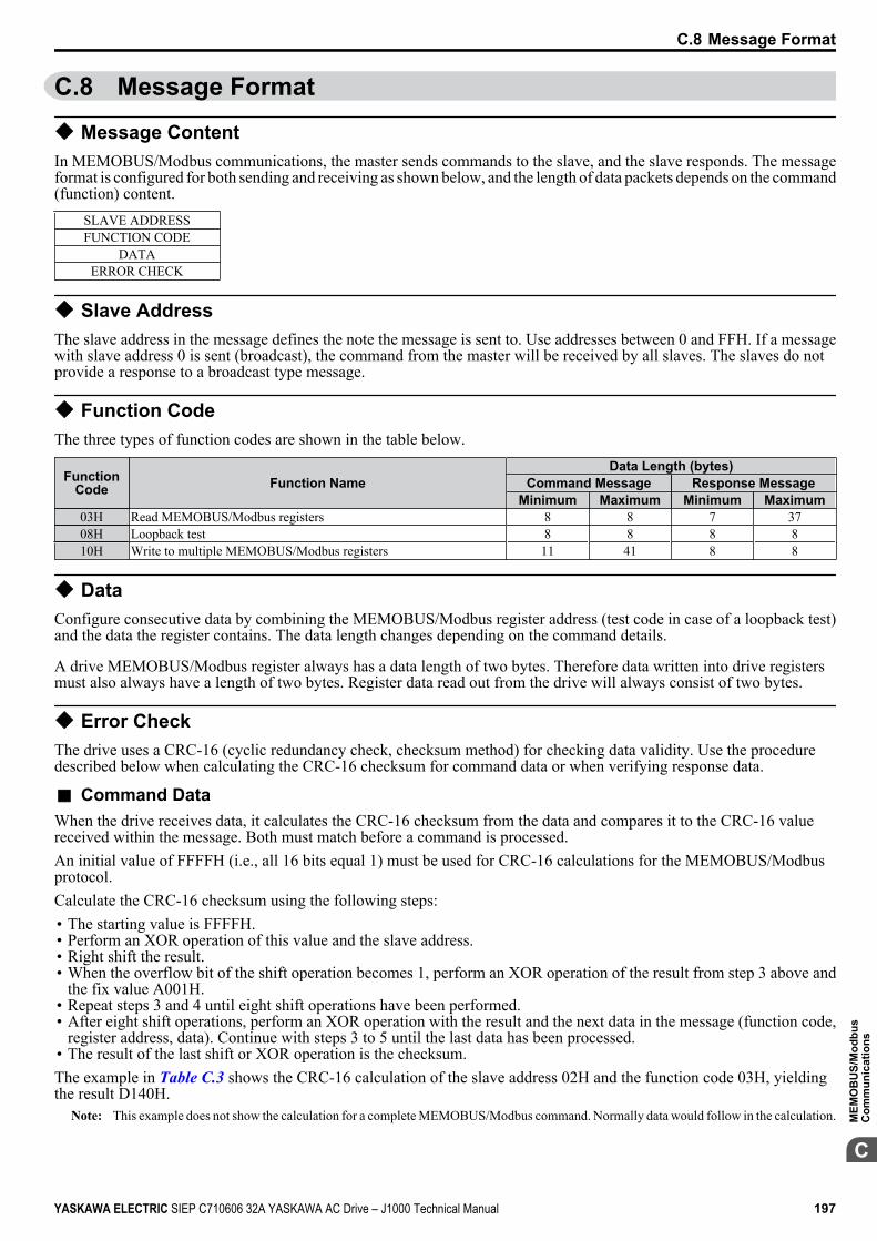
C.8 Message Format
u Message ContentIn MEMOBUS/Modbus communications, the master sends commands to the slave, and the slave responds. The messageformat is configured for both sending and receiving as shown below, and the length of data packets depends on the command(function) content.
SLAVE ADDRESSFUNCTION CODE
DATAERROR CHECK
u Slave AddressThe slave address in the message defines the note the message is sent to. Use addresses between 0 and FFH. If a messagewith slave address 0 is sent (broadcast), the command from the master will be received by all slaves. The slaves do notprovide a response to a broadcast type message.
u Function CodeThe three types of function codes are shown in the table below.
FunctionCode Function Name
Data Length (bytes)Command Message Response Message
Minimum Maximum Minimum Maximum03H Read MEMOBUS/Modbus registers 8 8 7 3708H Loopback test 8 8 8 810H Write to multiple MEMOBUS/Modbus registers 11 41 8 8
u DataConfigure consecutive data by combining the MEMOBUS/Modbus register address (test code in case of a loopback test)and the data the register contains. The data length changes depending on the command details.
A drive MEMOBUS/Modbus register always has a data length of two bytes. Therefore data written into drive registersmust also always have a length of two bytes. Register data read out from the drive will always consist of two bytes.
u Error CheckThe drive uses a CRC-16 (cyclic redundancy check, checksum method) for checking data validity. Use the proceduredescribed below when calculating the CRC-16 checksum for command data or when verifying response data.
n Command DataWhen the drive receives data, it calculates the CRC-16 checksum from the data and compares it to the CRC-16 valuereceived within the message. Both must match before a command is processed.An initial value of FFFFH (i.e., all 16 bits equal 1) must be used for CRC-16 calculations for the MEMOBUS/Modbusprotocol.Calculate the CRC-16 checksum using the following steps:• The starting value is FFFFH.• Perform an XOR operation of this value and the slave address.• Right shift the result.• When the overflow bit of the shift operation becomes 1, perform an XOR operation of the result from step 3 above and
the fix value A001H.• Repeat steps 3 and 4 until eight shift operations have been performed.• After eight shift operations, perform an XOR operation with the result and the next data in the message (function code,
register address, data). Continue with steps 3 to 5 until the last data has been processed.• The result of the last shift or XOR operation is the checksum.The example in Table C.3 shows the CRC-16 calculation of the slave address 02H and the function code 03H, yieldingthe result D140H.
Note: This example does not show the calculation for a complete MEMOBUS/Modbus command. Normally data would follow in the calculation.
C.8 Message Format
YASKAWA ELECTRIC SIEP C710606 32A YASKAWA AC Drive – J1000 Technical Manual 197
C
MEM
OB
US/
Mod
bus
Com
mun
icat
ions

Table C.3 CRC-16 Checksum Calculation ExampleDescription Calculation Overflow Description Calculation Overflow
Initial Value (FFFFH) 1111 1111 1111 1111 Function Code 03H 0000 0000 0000 0011 Address 02H 0000 0000 0000 0010 XOR w result 1000 0001 0011 1101
XOR w initial value 1111 1111 1111 1101 Shift 1 0100 0000 1001 1110 1Shift 1 0111 1111 1111 1110 1 XOR w A001H 1010 0000 0000 0001
XOR w A001H 1010 0000 0000 0001 XOR result 1110 0000 1001 1111 XOR result 1101 1111 1111 1111 Shift 2 0111 0000 0100 1111 1
Shift 2 0110 1111 1111 1111 1 XOR w A001H 1010 0000 0000 0001 XOR w A001H 1010 0000 0000 0001 XOR result 1101 0000 0100 1110
XOR result 1100 1111 1111 1110 Shift 3 0110 1000 0010 0111 0Shift 3 0110 0111 1111 1111 0 Shift 4 0011 0100 0001 0011 0Shift 4 0011 0011 1111 1111 1 XOR w A001H 1010 0000 0000 0001
XOR w A001H 1010 0000 0000 0001 XOR result 1001 0100 0001 0010 XOR result 1001 0011 1111 1110 Shift 5 0100 1010 0000 1001 0
Shift 5 0100 1001 1111 1111 0 Shift 6 0010 0101 0000 0100 1Shift 6 0010 0100 1111 1111 1 XOR w A001H 1010 0000 0000 0001
XOR w A001H 1010 0000 0000 0001 XOR result 1000 0101 0000 0101 XOR result 1000 0100 1111 1110 Shift 7 0100 0010 1000 0010 1
Shift 7 0100 0010 0111 1111 0 XOR w A001H 1010 0000 0000 0001 Shift 8 0010 0001 0011 1111 1 XOR result 1110 0010 1000 0011
XOR w A001H 1010 0000 0000 0001 Shift 8 0111 0001 0100 0001 1XOR result 1000 0001 0011 1110 XOR w A001H 1010 0000 0000 0001
Perform operations with next data (function code)
XOR result 1101 0001 0100 0000
CRC-16 1101 0001 0100 0000 D140H
Continue from here with next data.
n Response DataTo be sure that the data is valid, perform a CRC-16 calculation on the response message data as described above. Comparethe result to the CRC-16 checksum that was received within the response message. Both should match.
C.8 Message Format
198 YASKAWA ELECTRIC SIEP C710606 32A YASKAWA AC Drive – J1000 Technical Manual

C.9 Message ExamplesBelow are some examples of command and response messages.
u Reading Drive MEMOBUS/Modbus Register ContentsUsing the function code 03H (Read), a maximum of 16 MEMOBUS/Modbus registers can be read out at a time.The following table shows message examples when reading status signals, error details, data link status, and frequencyreferences from the slave 2 drive.
Command Message Response Message (normal) Response Message (fault)Slave Address 02H Slave Address 02H Slave Address 02HFunction Code 03H Function Code 03H Function Code 83H
Starting No. Upper 00H Data Quantity 08H Error Code 03HLower 20H 1st storage
registerUpper 00H CRC-16 Upper F1H
Data Quantity Upper 00H Lower 65H Lower 31HLower 04H Next storage
registerUpper 00H
CRC-16 Upper 45H Lower 00HLower F0H Next storage
registerUpper 00H
Lower 00H
Next storageregister
Upper 01H
Lower F4H
CRC-16 Upper AFHLower 82H
u Loopback TestFunction code 08H performs a loopback test. This test returns a response message with exactly the same content as thecommand message and can be used to check the communications between the master and slave. User-defined test codeand data values can be set.The following table shows a message example when performing a loopback test with the slave 1 drive.
Command Message Response Message (normal) Response Message (fault)Slave Address 01H Slave Address 01H Slave Address 01HFunction Code 08H Function Code 08H Function Code 89H
Test Code Upper 00H Test Code Upper 00H Error Code 01HLower 00H Lower 00H CRC-16 Upper 86H
Data Upper A5H Data Upper A5H Lower 50HLower 37H Lower 37H
CRC-16 Upper DAH CRC-16 Upper DAHLower 8DH Lower 8DH
C.9 Message Examples
YASKAWA ELECTRIC SIEP C710606 32A YASKAWA AC Drive – J1000 Technical Manual 199
C
MEM
OB
US/
Mod
bus
Com
mun
icat
ions
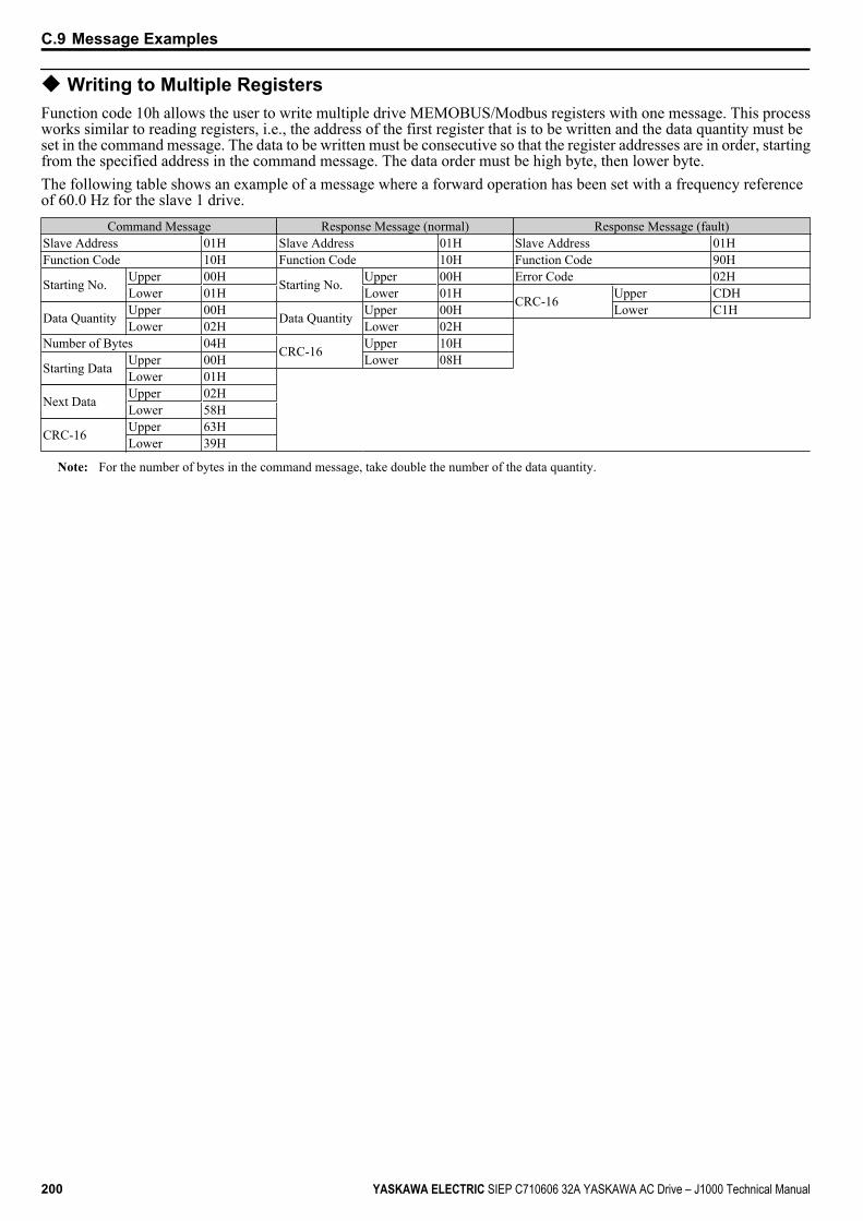
u Writing to Multiple RegistersFunction code 10h allows the user to write multiple drive MEMOBUS/Modbus registers with one message. This processworks similar to reading registers, i.e., the address of the first register that is to be written and the data quantity must beset in the command message. The data to be written must be consecutive so that the register addresses are in order, startingfrom the specified address in the command message. The data order must be high byte, then lower byte.The following table shows an example of a message where a forward operation has been set with a frequency referenceof 60.0 Hz for the slave 1 drive.
Command Message Response Message (normal) Response Message (fault)Slave Address 01H Slave Address 01H Slave Address 01HFunction Code 10H Function Code 10H Function Code 90H
Starting No. Upper 00H Starting No. Upper 00H Error Code 02HLower 01H Lower 01H CRC-16 Upper CDH
Data Quantity Upper 00H Data Quantity Upper 00H Lower C1HLower 02H Lower 02H
Number of Bytes 04H CRC-16 Upper 10H
Starting Data Upper 00H Lower 08H Lower 01H
Next Data Upper 02H Lower 58H
CRC-16 Upper 63H Lower 39H
Note: For the number of bytes in the command message, take double the number of the data quantity.
C.9 Message Examples
200 YASKAWA ELECTRIC SIEP C710606 32A YASKAWA AC Drive – J1000 Technical Manual
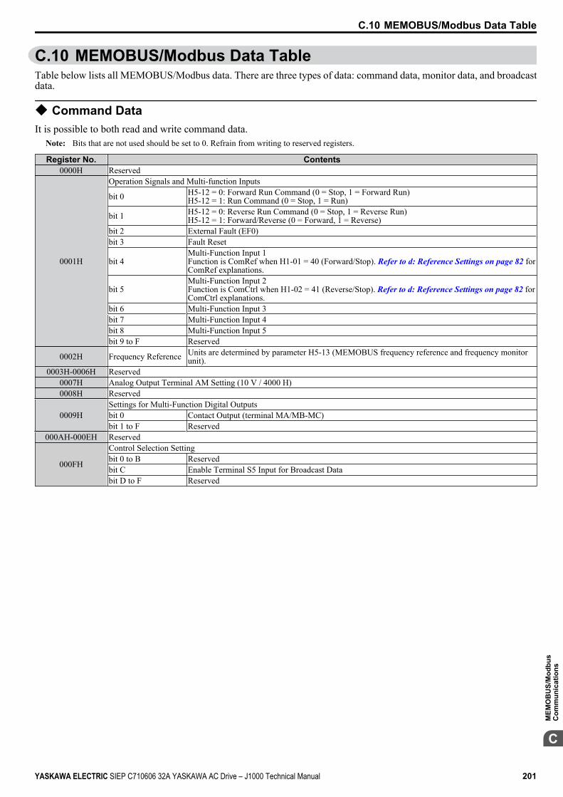
C.10 MEMOBUS/Modbus Data TableTable below lists all MEMOBUS/Modbus data. There are three types of data: command data, monitor data, and broadcastdata.
u Command DataIt is possible to both read and write command data.
Note: Bits that are not used should be set to 0. Refrain from writing to reserved registers.
Register No. Contents0000H Reserved
0001H
Operation Signals and Multi-function Inputs
bit 0 H5-12 = 0: Forward Run Command (0 = Stop, 1 = Forward Run)H5-12 = 1: Run Command (0 = Stop, 1 = Run)
bit 1 H5-12 = 0: Reverse Run Command (0 = Stop, 1 = Reverse Run)H5-12 = 1: Forward/Reverse (0 = Forward, 1 = Reverse)
bit 2 External Fault (EF0)bit 3 Fault Reset
bit 4Multi-Function Input 1Function is ComRef when H1-01 = 40 (Forward/Stop). Refer to d: Reference Settings on page 82 forComRef explanations.
bit 5Multi-Function Input 2Function is ComCtrl when H1-02 = 41 (Reverse/Stop). Refer to d: Reference Settings on page 82 forComCtrl explanations.
bit 6 Multi-Function Input 3bit 7 Multi-Function Input 4bit 8 Multi-Function Input 5bit 9 to F Reserved
0002H Frequency Reference Units are determined by parameter H5-13 (MEMOBUS frequency reference and frequency monitorunit).
0003H-0006H Reserved0007H Analog Output Terminal AM Setting (10 V / 4000 H)0008H Reserved
0009HSettings for Multi-Function Digital Outputsbit 0 Contact Output (terminal MA/MB-MC)bit 1 to F Reserved
000AH-000EH Reserved
000FH
Control Selection Settingbit 0 to B Reservedbit C Enable Terminal S5 Input for Broadcast Databit D to F Reserved
C.10 MEMOBUS/Modbus Data Table
YASKAWA ELECTRIC SIEP C710606 32A YASKAWA AC Drive – J1000 Technical Manual 201
C
MEM
OB
US/
Mod
bus
Com
mun
icat
ions
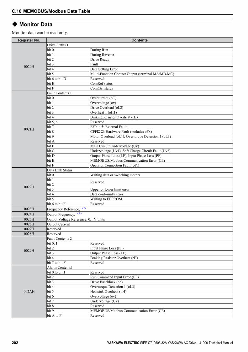
u Monitor DataMonitor data can be read only.
Register No. Contents
0020H
Drive Status 1bit 0 During Runbit 1 During Reversebit 2 Drive Readybit 3 Faultbit 4 Data Setting Errorbit 5 Multi-Function Contact Output (terminal MA/MB-MC)bit 6 to bit D Reservedbit E ComRef statusbit F ComCtrl status
0021H
Fault Contents 1bit 0 Overcurrent (oC)bit 1 Overvoltage (ov)bit 2 Drive Overload (oL2)bit 3 Overheat 1 (oH1)bit 4 Braking Resistor Overheat (rH)bit 5, 6 Reservedbit 7 EF0 to 5: External Faultbit 8 CPFoo: Hardware Fault (includes oFx)bit 9 Motor Overload (oL1), Overtorque Detection 1 (oL3)bit A Reservedbit B Main Circuit Undervoltage (Uv)bit C Undervoltage (Uv1), Soft Charge Circuit Fault (Uv3)bit D Output Phase Loss (LF), Input Phase Loss (PF)bit E MEMOBUS/Modbus Communication Error (CE)bit F Operator Connection Fault (oPr)
0022H
Data Link Statusbit 0 Writing data or switching motorsbit 1 Reservedbit 2bit 3 Upper or lower limit errorbit 4 Data conformity errorbit 5 Writing to EEPROMbit 6 to bit F Reserved
0023H Frequency Reference, <1>
0024H Output Frequency, <1>
0025H Output Voltage Reference, 0.1 V units0026H Output Current0027H Reserved0028H Reserved
0029H
Fault Contents 2bit 0, 1 Reservedbit 2 Input Phase Loss (PF)bit 3 Output Phase Loss (LF)bit 4 Braking Resistor Overheat (rH)bit 5 to bit F Reserved
002AH
Alarm Contents1bit 0 to bit 1 Reservedbit 2 Run Command Input Error (EF)bit 3 Drive Baseblock (bb)bit 4 Overtorque Detection 1 (oL3)bit 5 Heatsink Overheat (oH)bit 6 Overvoltage (ov)bit 7 Undervoltage (Uv)bit 8 Reservedbit 9 MEMOBUS/Modbus Communication Error (CE)bit A to F Reserved
C.10 MEMOBUS/Modbus Data Table
202 YASKAWA ELECTRIC SIEP C710606 32A YASKAWA AC Drive – J1000 Technical Manual
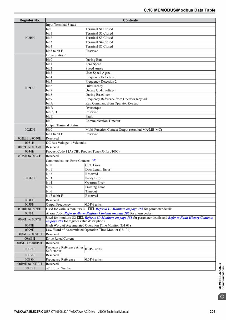
Register No. Contents
002BH
Input Terminal Statusbit 0 Terminal S1 Closedbit 1 Terminal S2 Closedbit 2 Terminal S3 Closedbit 3 Terminal S4 Closedbit 4 Terminal S5 Closedbit 5 to bit F Reserved
002CH
Drive Status 2bit 0 During Runbit 1 Zero Speedbit 2 Speed Agreebit 3 User Speed Agreebit 4 Frequency Detection 1bit 5 Frequency Detection 2bit 6 Drive Readybit 7 During Undervoltagebit 8 During Baseblockbit 9 Frequency Reference from Operator Keypadbit A Run Command from Operator Keypadbit B Overtorquebit C, D Reservedbit E Faultbit F Communication Timeout
002DHOutput Terminal Statusbit 0 Multi-Function Contact Output (terminal MA/MB-MC)bit 1 to bit F Reserved
002EH to 0030H Reserved0031H DC Bus Voltage, 1 Vdc units
0032H to 0033H Reserved0034H Product Code 1 [ASCII], Product Type (J0 for J1000)
0035H to 003CH Reserved
003DH
Communications Error Contents <2>
bit 0 CRC Errorbit 1 Data Length Errorbit 2 Reservedbit 3 Parity Errorbit 4 Overrun Errorbit 5 Framing Errorbit 6 Timeoutbit 7 to bit F Reserved
003EH Reserved003FH Output Frequency 0.01% units
0040H to 007EH Used for various monitors U1-oo. Refer to U: Monitors on page 183 for parameter details.007FH Alarm Code, Refer to Alarm Register Contents on page 206 for alarm codes.
0080H to 0097H Used for monitors U2-oo. Refer to U: Monitors on page 183 for parameter details and Refer to Fault History Contents on page 205 for register value descriptions.
0098H High Word of Accumulated Operation Time Monitor (U4-01)0099H Low Word of Accumulated Operation Time Monitor (U4-01)
009AH to 009BH Reserved00ABH Drive Rated Current
00ACH to 00B5H Reserved
00B6H Frequency Reference AfterSoft-starter 0.01% units
00B7H Reserved00B8H Frequency Reference 0.01% units
00B9H to 00BEH Reserved00BFH oPE Error Number
C.10 MEMOBUS/Modbus Data Table
YASKAWA ELECTRIC SIEP C710606 32A YASKAWA AC Drive – J1000 Technical Manual 203
C
MEM
OB
US/
Mod
bus
Com
mun
icat
ions
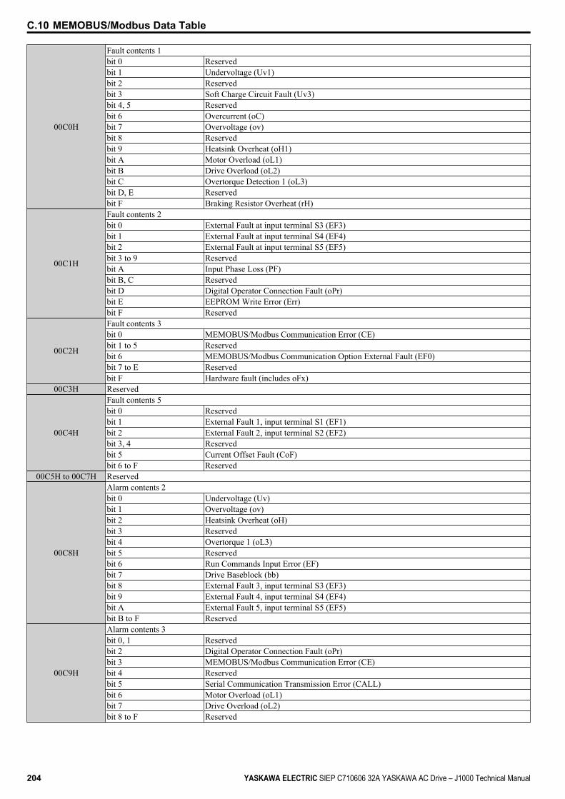
00C0H
Fault contents 1bit 0 Reservedbit 1 Undervoltage (Uv1)bit 2 Reservedbit 3 Soft Charge Circuit Fault (Uv3)bit 4, 5 Reservedbit 6 Overcurrent (oC)bit 7 Overvoltage (ov)bit 8 Reservedbit 9 Heatsink Overheat (oH1)bit A Motor Overload (oL1)bit B Drive Overload (oL2)bit C Overtorque Detection 1 (oL3)bit D, E Reservedbit F Braking Resistor Overheat (rH)
00C1H
Fault contents 2bit 0 External Fault at input terminal S3 (EF3)bit 1 External Fault at input terminal S4 (EF4)bit 2 External Fault at input terminal S5 (EF5)bit 3 to 9 Reservedbit A Input Phase Loss (PF)bit B, C Reservedbit D Digital Operator Connection Fault (oPr)bit E EEPROM Write Error (Err)bit F Reserved
00C2H
Fault contents 3bit 0 MEMOBUS/Modbus Communication Error (CE)bit 1 to 5 Reservedbit 6 MEMOBUS/Modbus Communication Option External Fault (EF0)bit 7 to E Reservedbit F Hardware fault (includes oFx)
00C3H Reserved
00C4H
Fault contents 5bit 0 Reservedbit 1 External Fault 1, input terminal S1 (EF1)bit 2 External Fault 2, input terminal S2 (EF2)bit 3, 4 Reservedbit 5 Current Offset Fault (CoF)bit 6 to F Reserved
00C5H to 00C7H Reserved
00C8H
Alarm contents 2bit 0 Undervoltage (Uv)bit 1 Overvoltage (ov)bit 2 Heatsink Overheat (oH)bit 3 Reservedbit 4 Overtorque 1 (oL3)bit 5 Reservedbit 6 Run Commands Input Error (EF)bit 7 Drive Baseblock (bb)bit 8 External Fault 3, input terminal S3 (EF3)bit 9 External Fault 4, input terminal S4 (EF4)bit A External Fault 5, input terminal S5 (EF5)bit B to F Reserved
00C9H
Alarm contents 3bit 0, 1 Reservedbit 2 Digital Operator Connection Fault (oPr)bit 3 MEMOBUS/Modbus Communication Error (CE)bit 4 Reservedbit 5 Serial Communication Transmission Error (CALL)bit 6 Motor Overload (oL1)bit 7 Drive Overload (oL2)bit 8 to F Reserved
C.10 MEMOBUS/Modbus Data Table
204 YASKAWA ELECTRIC SIEP C710606 32A YASKAWA AC Drive – J1000 Technical Manual
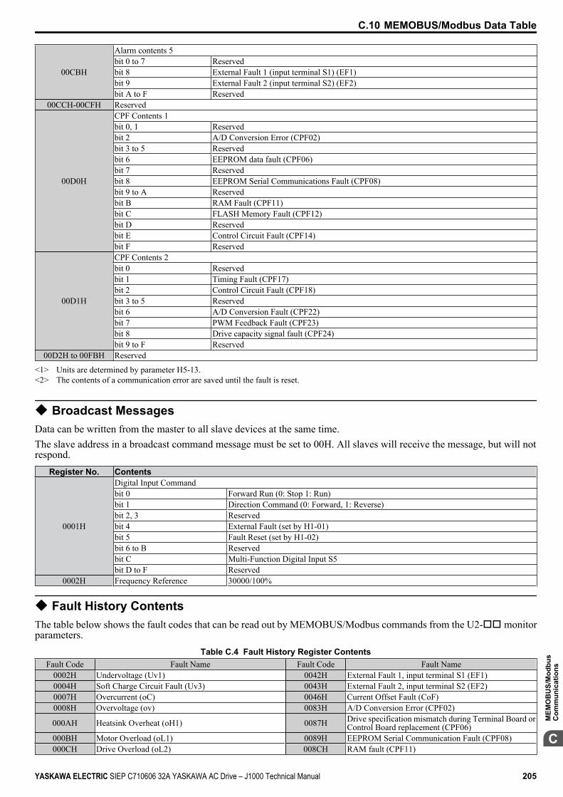
00CBH
Alarm contents 5bit 0 to 7 Reservedbit 8 External Fault 1 (input terminal S1) (EF1)bit 9 External Fault 2 (input terminal S2) (EF2)bit A to F Reserved
00CCH-00CFH Reserved
00D0H
CPF Contents 1bit 0, 1 Reservedbit 2 A/D Conversion Error (CPF02)bit 3 to 5 Reservedbit 6 EEPROM data fault (CPF06)bit 7 Reservedbit 8 EEPROM Serial Communications Fault (CPF08)bit 9 to A Reservedbit B RAM Fault (CPF11)bit C FLASH Memory Fault (CPF12)bit D Reservedbit E Control Circuit Fault (CPF14)bit F Reserved
00D1H
CPF Contents 2bit 0 Reservedbit 1 Timing Fault (CPF17)bit 2 Control Circuit Fault (CPF18)bit 3 to 5 Reservedbit 6 A/D Conversion Fault (CPF22)bit 7 PWM Feedback Fault (CPF23)bit 8 Drive capacity signal fault (CPF24)bit 9 to F Reserved
00D2H to 00FBH Reserved
<1> Units are determined by parameter H5-13.<2> The contents of a communication error are saved until the fault is reset.
u Broadcast MessagesData can be written from the master to all slave devices at the same time.The slave address in a broadcast command message must be set to 00H. All slaves will receive the message, but will notrespond.
Register No. Contents
0001H
Digital Input Commandbit 0 Forward Run (0: Stop 1: Run)bit 1 Direction Command (0: Forward, 1: Reverse)bit 2, 3 Reservedbit 4 External Fault (set by H1-01)bit 5 Fault Reset (set by H1-02)bit 6 to B Reservedbit C Multi-Function Digital Input S5bit D to F Reserved
0002H Frequency Reference 30000/100%
u Fault History ContentsThe table below shows the fault codes that can be read out by MEMOBUS/Modbus commands from the U2-oo monitorparameters.
Table C.4 Fault History Register ContentsFault Code Fault Name Fault Code Fault Name
0002H Undervoltage (Uv1) 0042H External Fault 1, input terminal S1 (EF1)0004H Soft Charge Circuit Fault (Uv3) 0043H External Fault 2, input terminal S2 (EF2)0007H Overcurrent (oC) 0046H Current Offset Fault (CoF)0008H Overvoltage (ov) 0083H A/D Conversion Error (CPF02)
000AH Heatsink Overheat (oH1) 0087H Drive specification mismatch during Terminal Board orControl Board replacement (CPF06)
000BH Motor Overload (oL1) 0089H EEPROM Serial Communication Fault (CPF08)000CH Drive Overload (oL2) 008CH RAM fault (CPF11)
C.10 MEMOBUS/Modbus Data Table
YASKAWA ELECTRIC SIEP C710606 32A YASKAWA AC Drive – J1000 Technical Manual 205
C
MEM
OB
US/
Mod
bus
Com
mun
icat
ions
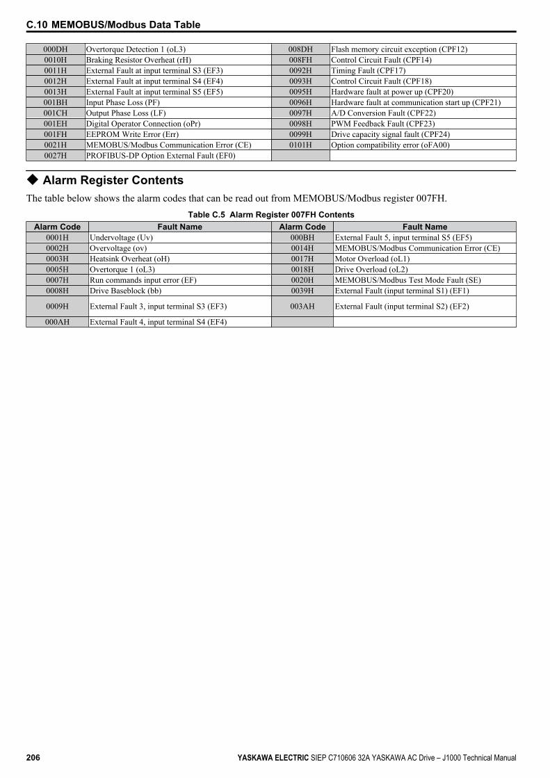
000DH Overtorque Detection 1 (oL3) 008DH Flash memory circuit exception (CPF12)0010H Braking Resistor Overheat (rH) 008FH Control Circuit Fault (CPF14)0011H External Fault at input terminal S3 (EF3) 0092H Timing Fault (CPF17)0012H External Fault at input terminal S4 (EF4) 0093H Control Circuit Fault (CPF18)0013H External Fault at input terminal S5 (EF5) 0095H Hardware fault at power up (CPF20)001BH Input Phase Loss (PF) 0096H Hardware fault at communication start up (CPF21)001CH Output Phase Loss (LF) 0097H A/D Conversion Fault (CPF22)001EH Digital Operator Connection (oPr) 0098H PWM Feedback Fault (CPF23)001FH EEPROM Write Error (Err) 0099H Drive capacity signal fault (CPF24)0021H MEMOBUS/Modbus Communication Error (CE) 0101H Option compatibility error (oFA00)0027H PROFIBUS-DP Option External Fault (EF0)
u Alarm Register ContentsThe table below shows the alarm codes that can be read out from MEMOBUS/Modbus register 007FH.
Table C.5 Alarm Register 007FH ContentsAlarm Code Fault Name Alarm Code Fault Name
0001H Undervoltage (Uv) 000BH External Fault 5, input terminal S5 (EF5)0002H Overvoltage (ov) 0014H MEMOBUS/Modbus Communication Error (CE)0003H Heatsink Overheat (oH) 0017H Motor Overload (oL1)0005H Overtorque 1 (oL3) 0018H Drive Overload (oL2)0007H Run commands input error (EF) 0020H MEMOBUS/Modbus Test Mode Fault (SE)0008H Drive Baseblock (bb) 0039H External Fault (input terminal S1) (EF1)
0009H External Fault 3, input terminal S3 (EF3) 003AH External Fault (input terminal S2) (EF2)
000AH External Fault 4, input terminal S4 (EF4)
C.10 MEMOBUS/Modbus Data Table
206 YASKAWA ELECTRIC SIEP C710606 32A YASKAWA AC Drive – J1000 Technical Manual

C.11 Changing Drive ParametersThis section describes how the drive handles parameter changes by MEMOBUS/Modbus.
u Drive Operations on Parameter ChangeWhen drive parameters are changed by MEMOBUS/Modbus communication, the drive performs the following operations:• The upper/lower limit of the parameter changed is checked. If the new value is out of range, the old value remains active.• Parameter settings are refreshed in the RAM, i.e., the parameter change is activated immediately.• The default settings of related parameters are changed.• If multiple registers are written and only one data is invalid, all data sent are discarded.If no Enter command is sent, parameter changes will be lost if the power is switched off.
u Issuing an Enter CommandIf parameters are changed from a PLC using MEMOBUS/Modbus communication the values are changed in the driveRAM only. When the power is turned off all changes will be lost. An Enter command can be sent to save changes in theEEPROM (non-volatile memory) and thereby prevent the loss of parameter settings. In order to perform an Enter command"0" must be written in register number 900H. This register is "write only".
Table C.6 Enter CommandRegister No. Description
0900H Writes data into the EEPROM (non-volatile memory). Parameter changes remain even if the power supply is cycled.
Note: Because the EEPROM can be written to a maximum of 100,000 times, refrain from writing to the EEPROM too often. The Enter commandregisters are write-only. Consequently, if these registers are read, then the register address will be invalid (Error code: 02H). An Entercommand is not required if reference or broadcast data are sent to the drive.
C.11 Changing Drive Parameters
YASKAWA ELECTRIC SIEP C710606 32A YASKAWA AC Drive – J1000 Technical Manual 207
C
MEM
OB
US/
Mod
bus
Com
mun
icat
ions
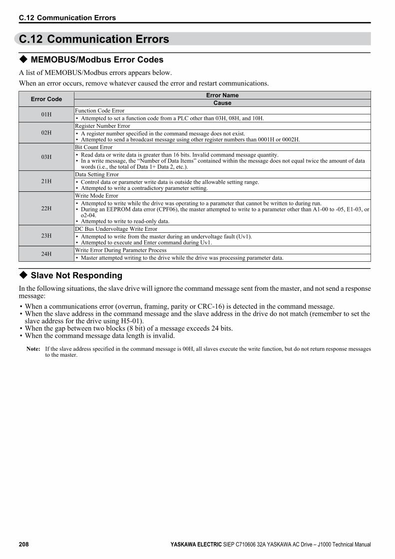
C.12 Communication Errors
u MEMOBUS/Modbus Error CodesA list of MEMOBUS/Modbus errors appears below.When an error occurs, remove whatever caused the error and restart communications.
Error Code Error NameCause
01H Function Code Error• Attempted to set a function code from a PLC other than 03H, 08H, and 10H.
02HRegister Number Error• A register number specified in the command message does not exist.• Attempted to send a broadcast message using other register numbers than 0001H or 0002H.
03HBit Count Error• Read data or write data is greater than 16 bits. Invalid command message quantity.• In a write message, the “Number of Data Items” contained within the message does not equal twice the amount of data
words (i.e., the total of Data 1+ Data 2, etc.).
21HData Setting Error• Control data or parameter write data is outside the allowable setting range.• Attempted to write a contradictory parameter setting.
22H
Write Mode Error• Attempted to write while the drive was operating to a parameter that cannot be written to during run.• During an EEPROM data error (CPF06), the master attempted to write to a parameter other than A1-00 to -05, E1-03, or
o2-04.• Attempted to write to read-only data.
23HDC Bus Undervoltage Write Error• Attempted to write from the master during an undervoltage fault (Uv1).• Attempted to execute and Enter command during Uv1.
24H Write Error During Parameter Process• Master attempted writing to the drive while the drive was processing parameter data.
u Slave Not RespondingIn the following situations, the slave drive will ignore the command message sent from the master, and not send a responsemessage:• When a communications error (overrun, framing, parity or CRC-16) is detected in the command message.• When the slave address in the command message and the slave address in the drive do not match (remember to set the
slave address for the drive using H5-01).• When the gap between two blocks (8 bit) of a message exceeds 24 bits.• When the command message data length is invalid.
Note: If the slave address specified in the command message is 00H, all slaves execute the write function, but do not return response messagesto the master.
C.12 Communication Errors
208 YASKAWA ELECTRIC SIEP C710606 32A YASKAWA AC Drive – J1000 Technical Manual
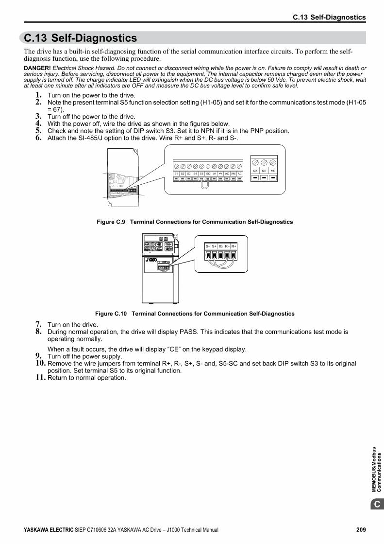
C.13 Self-DiagnosticsThe drive has a built-in self-diagnosing function of the serial communication interface circuits. To perform the self-diagnosis function, use the following procedure.DANGER! Electrical Shock Hazard. Do not connect or disconnect wiring while the power is on. Failure to comply will result in death orserious injury. Before servicing, disconnect all power to the equipment. The internal capacitor remains charged even after the powersupply is turned off. The charge indicator LED will extinguish when the DC bus voltage is below 50 Vdc. To prevent electric shock, waitat least one minute after all indicators are OFF and measure the DC bus voltage level to confirm safe level.
1. Turn on the power to the drive.2. Note the present terminal S5 function selection setting (H1-05) and set it for the communications test mode (H1-05
= 67).3. Turn off the power to the drive.4. With the power off, wire the drive as shown in the figures below.5. Check and note the setting of DIP switch S3. Set it to NPN if it is in the PNP position.6. Attach the SI-485/J option to the drive. Wire R+ and S+, R- and S-.
S1 S2 S3 S4 S5 SC A1 +V AC AM ACMCMBMA
Figure C.9 Terminal Connections for Communication Self-Diagnostics
S– S+ IG R– R+
Figure C.10 Terminal Connections for Communication Self-Diagnostics
7. Turn on the drive.8. During normal operation, the drive will display PASS. This indicates that the communications test mode is
operating normally.When a fault occurs, the drive will display “CE” on the keypad display.
9. Turn off the power supply.10. Remove the wire jumpers from terminal R+, R-, S+, S- and, S5-SC and set back DIP switch S3 to its original
position. Set terminal S5 to its original function.11. Return to normal operation.
C.13 Self-Diagnostics
YASKAWA ELECTRIC SIEP C710606 32A YASKAWA AC Drive – J1000 Technical Manual 209
C
MEM
OB
US/
Mod
bus
Com
mun
icat
ions
C.13 Self-Diagnostics
This Page Intentionally Blank
210 YASKAWA ELECTRIC SIEP C710606 32A YASKAWA AC Drive – J1000 Technical Manual
Standards ComplianceThis appendix explains the guidelines and criteria for maintaining CE and UL standards.
D.1 SECTION SAFETY..........................................................................................212D.2 EUROPEAN STANDARDS.............................................................................214D.3 UL STANDARDS.............................................................................................219D.4 USER SETTING TABLE.................................................................................222
Appendix: D
YASKAWA ELECTRIC SIEP C710606 32A YASKAWA AC Drive – J1000 Technical Manual 211
D.1 Section Safety DANGER
Electrical Shock HazardDo not connect or disconnect wiring while the power is on.Failure to comply will result in death or serious injury.
WARNINGElectrical Shock Hazard
Do not operate equipment with covers removed.Failure to comply could result in death or serious injury.The diagrams in this section may show drives without covers or safety shields to show details. Be sure to reinstall coversor shields before operating the drives and run the drives according to the instructions described in this manual.Always ground the motor-side grounding terminal.Improper equipment grounding could result in death or serious injury by contacting the motor case.Do not touch any terminals before the capacitors have fully discharged.Failure to comply could result in death or serious injury.Before wiring terminals, disconnect all power to the equipment. The internal capacitor remains charged even after thepower supply is turned off. The charge indicator LED will extinguish when the DC bus voltage is below 50 Vdc. Toprevent electric shock, wait at least one minute after all indicators are off and measure the DC bus voltage level to confirmsafe level.
WARNINGDo not allow unqualified personnel to perform work on the drive.Failure to comply could result in death or serious injury.Installation, maintenance, inspection, and servicing must be performed only by authorized personnel familiar withinstallation, adjustment and maintenance of AC drives.Do not perform work on the drive while wearing loose clothing, jewelry or without eye protection.Failure to comply could result in death or serious injury.Remove all metal objects such as watches and rings, secure loose clothing, and wear eye protection before beginningwork on the drive.Do not remove covers or touch circuit boards while the power is on.Failure to comply could result in death or serious injury.
WARNINGFire Hazard
Tighten all terminal screws to the specified tightening torque.Loose electrical connections could result in death or serious injury by fire due to overheating of electrical connections.Do not use an improper voltage source.Failure to comply could result in death or serious injury by fire.Verify that the rated voltage of the drive matches the voltage of the incoming power supply before applying power.Do not use improper combustible materials.Failure to comply could result in death or serious injury by fire.Attach the drive to metal or other noncombustible material.
D.1 Section Safety
212 YASKAWA ELECTRIC SIEP C710606 32A YASKAWA AC Drive – J1000 Technical Manual
NOTICEObserve proper electrostatic discharge procedures (ESD) when handling the drive and circuit boards.Failure to comply may result in ESD damage to the drive circuitry.Never connect or disconnect the motor from the drive while the drive is outputting voltage.Improper equipment sequencing could result in damage to the drive.Do not use unshielded cable for control wiring.Failure to comply may cause electrical interference resulting in poor system performance. Use shielded twisted-pair wiresand ground the shield to the ground terminal of the drive.Do not allow unqualified personnel to use the product.Failure to comply could result in damage to the drive or braking circuit.Carefully review instruction manual TOBPC72060000 when connecting a braking option to the drive.Do not modify the drive circuitry.Failure to comply could result in damage to the drive and will void warranty.Yaskawa is not responsible for modification of the product made by the user. This product must not be modified.Check all the wiring to ensure that all connections are correct after installing the drive and connecting otherdevices.Failure to comply could result in damage to the drive.
D.1 Section Safety
YASKAWA ELECTRIC SIEP C710606 32A YASKAWA AC Drive – J1000 Technical Manual 213D
Stan
dard
s C
ompl
ianc
e
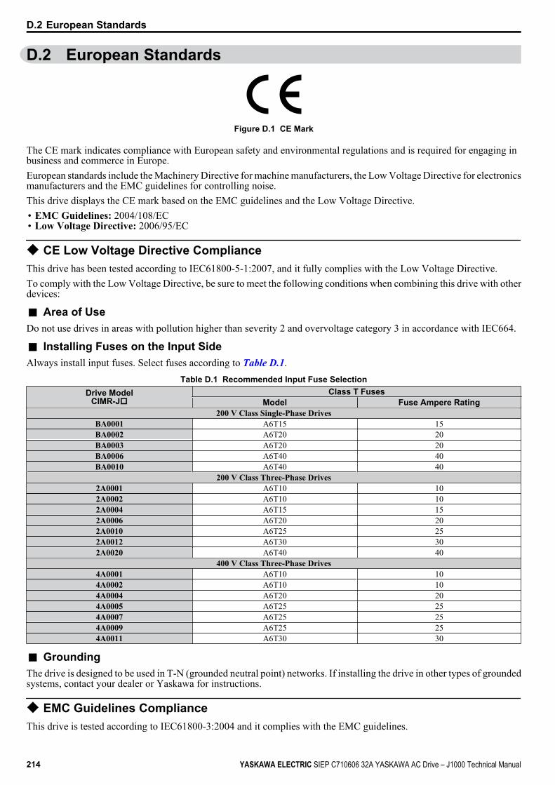
D.2 European Standards
Figure D.1 CE Mark
The CE mark indicates compliance with European safety and environmental regulations and is required for engaging inbusiness and commerce in Europe.European standards include the Machinery Directive for machine manufacturers, the Low Voltage Directive for electronicsmanufacturers and the EMC guidelines for controlling noise.This drive displays the CE mark based on the EMC guidelines and the Low Voltage Directive.• EMC Guidelines: 2004/108/EC• Low Voltage Directive: 2006/95/EC
u CE Low Voltage Directive ComplianceThis drive has been tested according to IEC61800-5-1:2007, and it fully complies with the Low Voltage Directive.To comply with the Low Voltage Directive, be sure to meet the following conditions when combining this drive with otherdevices:
n Area of UseDo not use drives in areas with pollution higher than severity 2 and overvoltage category 3 in accordance with IEC664.
n Installing Fuses on the Input SideAlways install input fuses. Select fuses according to Table D.1.
Table D.1 Recommended Input Fuse SelectionDrive Model
CIMR-JoClass T Fuses
Model Fuse Ampere Rating200 V Class Single-Phase Drives
BA0001 A6T15 15BA0002 A6T20 20BA0003 A6T20 20BA0006 A6T40 40BA0010 A6T40 40
200 V Class Three-Phase Drives2A0001 A6T10 102A0002 A6T10 102A0004 A6T15 152A0006 A6T20 202A0010 A6T25 252A0012 A6T30 302A0020 A6T40 40
400 V Class Three-Phase Drives4A0001 A6T10 104A0002 A6T10 104A0004 A6T20 204A0005 A6T25 254A0007 A6T25 254A0009 A6T25 254A0011 A6T30 30
n GroundingThe drive is designed to be used in T-N (grounded neutral point) networks. If installing the drive in other types of groundedsystems, contact your dealer or Yaskawa for instructions.
u EMC Guidelines ComplianceThis drive is tested according to IEC61800-3:2004 and it complies with the EMC guidelines.
D.2 European Standards
214 YASKAWA ELECTRIC SIEP C710606 32A YASKAWA AC Drive – J1000 Technical Manual
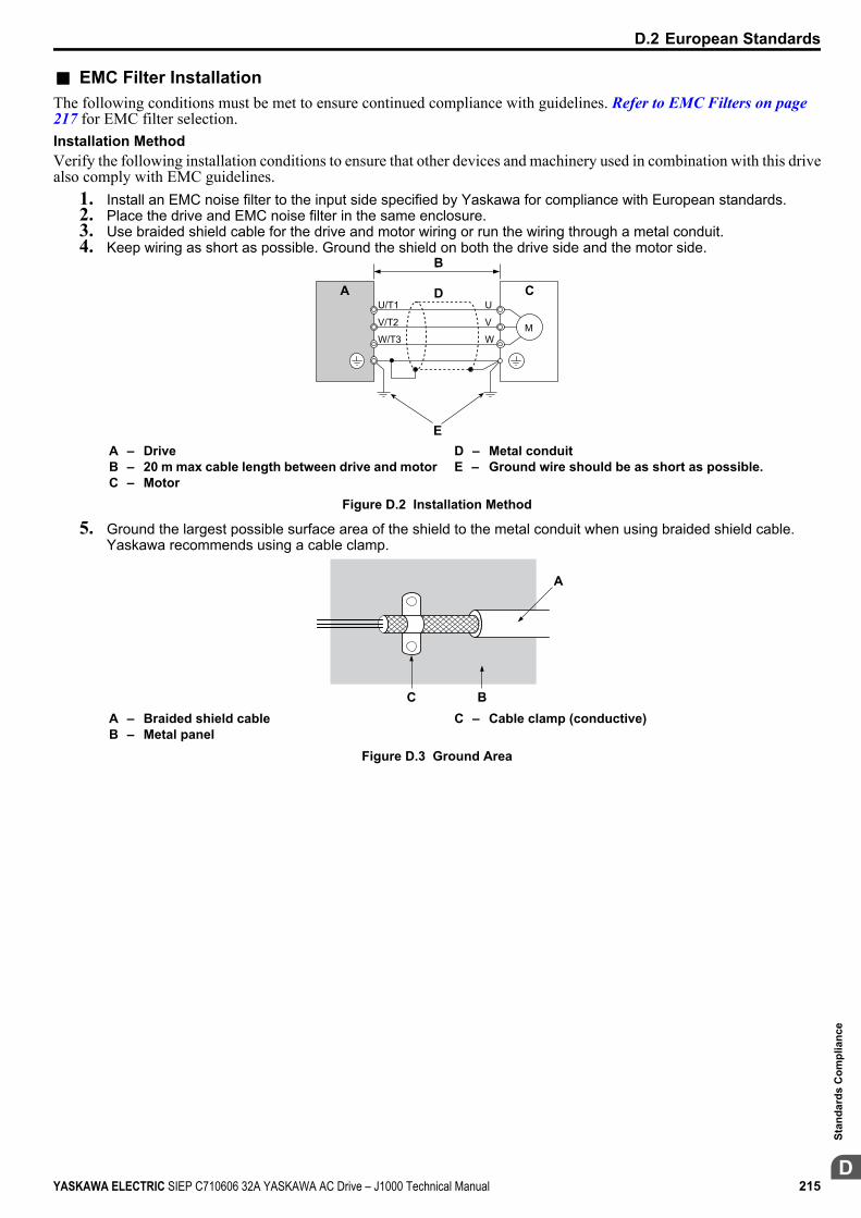
n EMC Filter InstallationThe following conditions must be met to ensure continued compliance with guidelines. Refer to EMC Filters on page 217 for EMC filter selection.Installation MethodVerify the following installation conditions to ensure that other devices and machinery used in combination with this drivealso comply with EMC guidelines.
1. Install an EMC noise filter to the input side specified by Yaskawa for compliance with European standards.2. Place the drive and EMC noise filter in the same enclosure.3. Use braided shield cable for the drive and motor wiring or run the wiring through a metal conduit.4. Keep wiring as short as possible. Ground the shield on both the drive side and the motor side.
A
B
D
E
C
M
U/T1
V/T2
W/T3
U
V
W
A – DriveB – 20 m max cable length between drive and motorC – Motor
D – Metal conduitE – Ground wire should be as short as possible.
Figure D.2 Installation Method
5. Ground the largest possible surface area of the shield to the metal conduit when using braided shield cable.Yaskawa recommends using a cable clamp.
C B
A
A – Braided shield cableB – Metal panel
C – Cable clamp (conductive)
Figure D.3 Ground Area
D.2 European Standards
YASKAWA ELECTRIC SIEP C710606 32A YASKAWA AC Drive – J1000 Technical Manual 215D
Stan
dard
s C
ompl
ianc
e
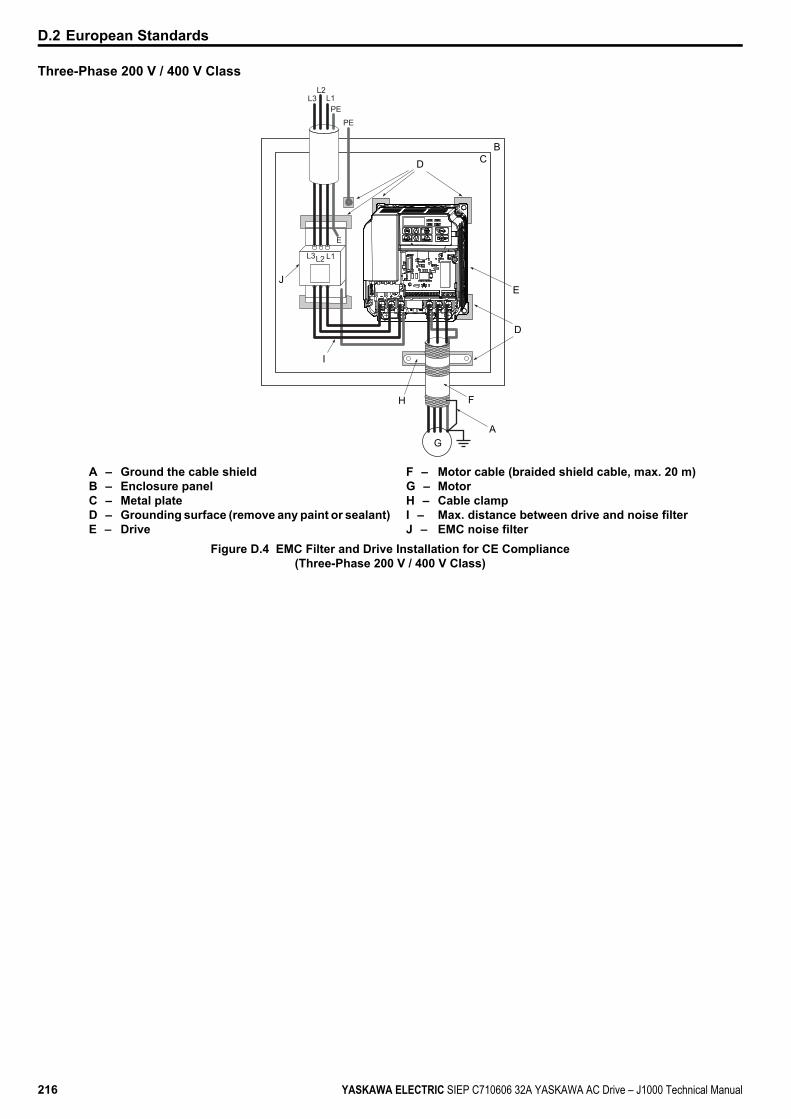
Three-Phase 200 V / 400 V Class
BCD
E
D
F
AG
J
I
H
L3L2 L1
E
L1PE
L3L2
PE
A – Ground the cable shieldB – Enclosure panelC – Metal plateD – Grounding surface (remove any paint or sealant)E – Drive
F – Motor cable (braided shield cable, max. 20 m)G – MotorH – Cable clampI – Max. distance between drive and noise filterJ – EMC noise filter
Figure D.4 EMC Filter and Drive Installation for CE Compliance(Three-Phase 200 V / 400 V Class)
D.2 European Standards
216 YASKAWA ELECTRIC SIEP C710606 32A YASKAWA AC Drive – J1000 Technical Manual
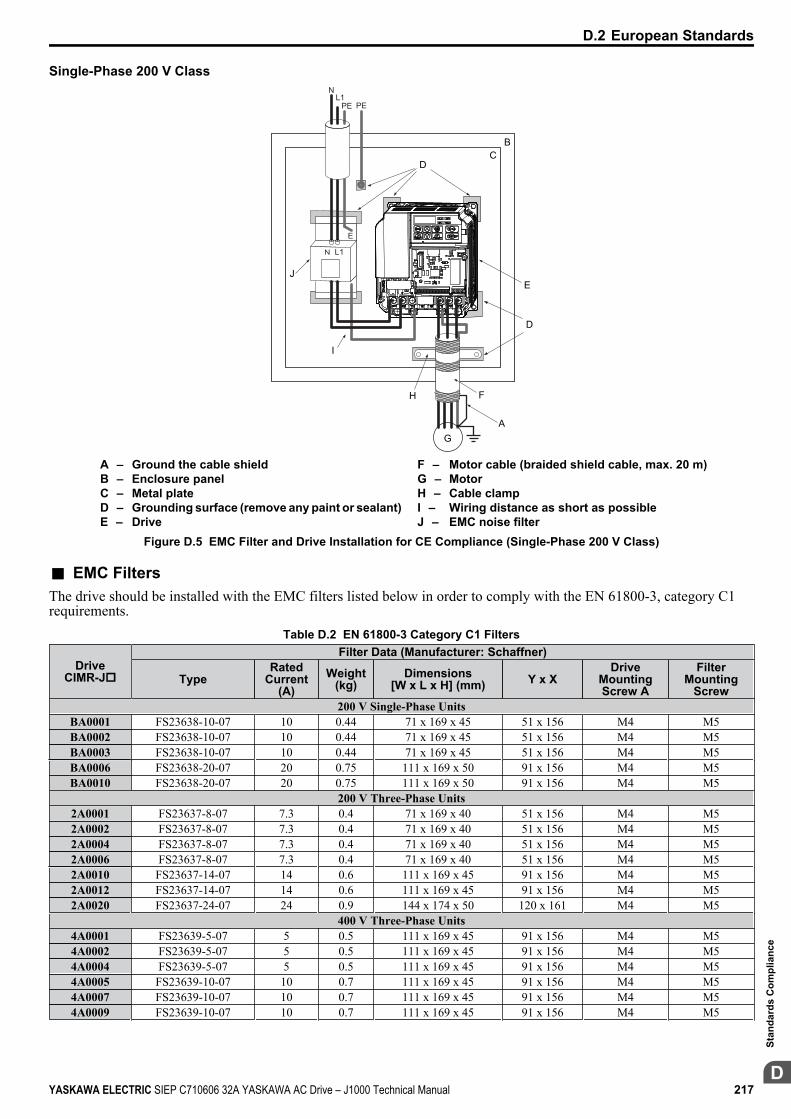
Single-Phase 200 V Class
BC
D
E
D
F
A
H
G
J
I
N L1
E
NL1
PE PE
A – Ground the cable shieldB – Enclosure panelC – Metal plateD – Grounding surface (remove any paint or sealant)E – Drive
F – Motor cable (braided shield cable, max. 20 m)G – MotorH – Cable clampI – Wiring distance as short as possibleJ – EMC noise filter
Figure D.5 EMC Filter and Drive Installation for CE Compliance (Single-Phase 200 V Class)
n EMC FiltersThe drive should be installed with the EMC filters listed below in order to comply with the EN 61800-3, category C1requirements.
Table D.2 EN 61800-3 Category C1 Filters
DriveCIMR-Jo
Filter Data (Manufacturer: Schaffner)
TypeRated
Current(A)
Weight(kg)
Dimensions[W x L x H] (mm) Y x X
DriveMountingScrew A
FilterMounting
Screw200 V Single-Phase Units
BA0001 FS23638-10-07 10 0.44 71 x 169 x 45 51 x 156 M4 M5BA0002 FS23638-10-07 10 0.44 71 x 169 x 45 51 x 156 M4 M5BA0003 FS23638-10-07 10 0.44 71 x 169 x 45 51 x 156 M4 M5BA0006 FS23638-20-07 20 0.75 111 x 169 x 50 91 x 156 M4 M5BA0010 FS23638-20-07 20 0.75 111 x 169 x 50 91 x 156 M4 M5
200 V Three-Phase Units2A0001 FS23637-8-07 7.3 0.4 71 x 169 x 40 51 x 156 M4 M52A0002 FS23637-8-07 7.3 0.4 71 x 169 x 40 51 x 156 M4 M52A0004 FS23637-8-07 7.3 0.4 71 x 169 x 40 51 x 156 M4 M52A0006 FS23637-8-07 7.3 0.4 71 x 169 x 40 51 x 156 M4 M52A0010 FS23637-14-07 14 0.6 111 x 169 x 45 91 x 156 M4 M52A0012 FS23637-14-07 14 0.6 111 x 169 x 45 91 x 156 M4 M52A0020 FS23637-24-07 24 0.9 144 x 174 x 50 120 x 161 M4 M5
400 V Three-Phase Units4A0001 FS23639-5-07 5 0.5 111 x 169 x 45 91 x 156 M4 M54A0002 FS23639-5-07 5 0.5 111 x 169 x 45 91 x 156 M4 M54A0004 FS23639-5-07 5 0.5 111 x 169 x 45 91 x 156 M4 M54A0005 FS23639-10-07 10 0.7 111 x 169 x 45 91 x 156 M4 M54A0007 FS23639-10-07 10 0.7 111 x 169 x 45 91 x 156 M4 M54A0009 FS23639-10-07 10 0.7 111 x 169 x 45 91 x 156 M4 M5
D.2 European Standards
YASKAWA ELECTRIC SIEP C710606 32A YASKAWA AC Drive – J1000 Technical Manual 217D
Stan
dard
s C
ompl
ianc
e
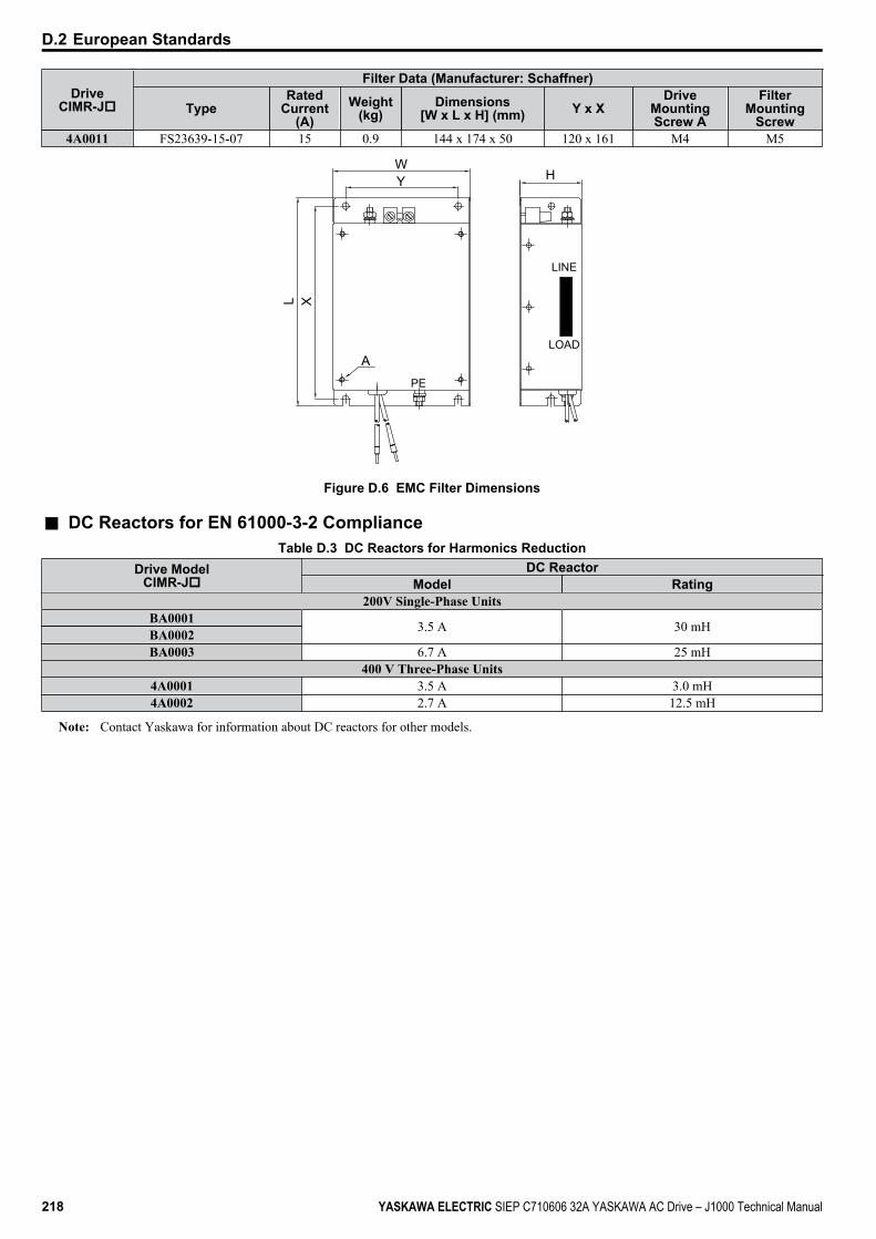
DriveCIMR-Jo
Filter Data (Manufacturer: Schaffner)
TypeRated
Current(A)
Weight(kg)
Dimensions[W x L x H] (mm) Y x X
DriveMountingScrew A
FilterMounting
Screw4A0011 FS23639-15-07 15 0.9 144 x 174 x 50 120 x 161 M4 M5
H
XL
WY
LINE
APE
LOAD
Figure D.6 EMC Filter Dimensions
n DC Reactors for EN 61000-3-2 ComplianceTable D.3 DC Reactors for Harmonics Reduction
Drive ModelCIMR-Jo
DC ReactorModel Rating
200V Single-Phase UnitsBA0001 3.5 A 30 mHBA0002BA0003 6.7 A 25 mH
400 V Three-Phase Units4A0001 3.5 A 3.0 mH4A0002 2.7 A 12.5 mH
Note: Contact Yaskawa for information about DC reactors for other models.
D.2 European Standards
218 YASKAWA ELECTRIC SIEP C710606 32A YASKAWA AC Drive – J1000 Technical Manual

D.3 UL StandardsThe UL/cUL mark applies to products in the United States and Canada indicates that UL has performed product testingand evaluation and determined that their stringent standards for product safety have been met. For a product to receive ULcertification, all components inside that product must also receive UL certification.
U LC R USLISTED
Figure D.7 UL/cUL Mark
u UL Standards ComplianceThis drive is tested in accordance with UL standard UL508C, E131457 and complies with UL requirements. The followingconditions must be met to maintain compliance when using this drive in combination with other equipment:
n Installation AreaDo not install the drive to an area greater than pollution severity 2 (UL standard).
n Main Circuit Terminal WiringYaskawa recommends using UL-listed copper wires (rated at 75 °C) and closed-loop connectors or CSA-certified ringconnectors sized for the selected wire gauge to maintain proper clearances when wiring the drive. Use the correct crimptool to install connectors per manufacturer recommendation. Table D.4 lists a suitable closed-loop connector manufacturedby JST Corporation.
Table D.4 Closed-Loop Crimp Terminal Size (JIS C 2805) (same for 200 V and 400 V)Wire Gaugemm2 (AWG)
TerminalScrews
Crimp TerminalModel Numbers
Tightening TorqueN m (lb to in.)
0.75 (18) M3.5 R1.25-3.5 0.8 to 1.0 (7.1 to 8.9)M4 R1.25-4 1.2 to 1.5 (10.6 to 13.3)
1.25 (16) M3.5 R1.25-3.5 0.8 to 1.0 (7.1 to 8.9)M4 R1.25-4 1.2 to 1.5 (10.6 to 13.3)
2 (14) M3.5 R2-3.5 0.8 to 1.0 (7.1 to 8.9)M4 R2-4 1.2 to 1.5 (10.6 to 13.3)
3.5/5.5 (12/10) M4 R5.5-4 1.2 to 1.5 (10.6 to 13.3)
Note: Use crimp insulated terminals or insulated shrink tubing for wiring connections. Wires should have a continuous maximum allowabletemperature of 75 °C 600 Vac UL-approved vinyl-sheathed insulation.
Table D.5 Recommended Input Fuse SelectionDrive Model
CIMR-JoClass T Fuses Class L Fuses
Model Fuse Ampere Rating Model Fuse Ampere Rating200 V Class Single-Phase Drives
BA0001 A6T15 15 CR6L-20/UL 20BA0002 A6T20 20 CR6L-30/UL 30BA0003 A6T20 20 CR6L-50/UL 50BA0006 A6T40 40 CR6L-75/UL 75BA0010 A6T40 40 CR6L-100/UL 100
200 V Class Three-Phase Drives2A0001 A6T10 10 CR6L-20/UL 202A0002 A6T10 10 CR6L-20/UL 202A0004 A6T15 15 CR6L-20/UL 202A0006 A6T20 20 CR6L-30/UL 302A0010 A6T25 25 CR6L-50/UL 502A0012 A6T30 30 CR6L-50/UL 502A0020 A6T40 40 CR6L-75/UL 75
400 V Class Three-Phase Drives4A0001 A6T10 10 CR6L-20/UL 204A0002 A6T10 10 CR6L-20/UL 204A0004 A6T20 20 CR6L-50/UL 504A0005 A6T25 25 CR6L-50/UL 504A0007 A6T25 25 CR6L-50/UL 504A0009 A6T25 25 CR6L-50/UL 50
D.3 UL Standards
YASKAWA ELECTRIC SIEP C710606 32A YASKAWA AC Drive – J1000 Technical Manual 219D
Stan
dard
s C
ompl
ianc
e
Drive ModelCIMR-Jo
Class T Fuses Class L FusesModel Fuse Ampere Rating Model Fuse Ampere Rating
4A0011 A6T30 30 CR6L-50/UL 50
n Low Voltage Wiring for Control Circuit TerminalsWire low voltage wires with NEC Class 1 circuit conductors. Refer to national state or local codes for wiring. Use a class2 (UL regulations) power supply for the control circuit terminal.
Table D.6 Control Circuit Terminal Power SupplyInput / Output Terminal Signal Power Supply Specifications
Multi-function digital inputs S1, S2, S3, S4, S5, SC Use the internal power supply of the drive. Use class 2for external power supply.
Main frequency reference +V, A1, AC Use the internal power supply of the drive. Use class 2for external power supply.
n Drive Short-Circuit RatingThis drive has undergone the UL short-circuit test, which certifies that during a short circuit in the power supply the currentflow will not rise above 30,000 amps maximum at 240 V for 200 V class drives and 480 V for 400 V class drives.• The MCCB and breaker protection and fuse ratings shall be equal to or greater than the short-circuit tolerance of the
power supply being used.• Suitable for use on a circuit capable of delivering not more than 30,000 RMS symmetrical amperes for 240 V in 200 V
class drives (up to 480 V for 400 V class drives) motor overload protection.
u Drive Motor Overload ProtectionSet parameter E2-01 (motor rated current) to the appropriate value to enable motor overload protection. The internal motoroverload protection is UL listed and in accordance with the NEC and CEC.
n E2-01 Motor Rated CurrentSetting Range: Model DependentDefault Setting: Model DependentParameter E2-01 (motor rated current) protects the motor if parameter L1-01 is not set to 0 (default is 1, standard inductionmotor protection enabled).
n L1-01 Motor Overload Protection SelectionThe drive has an electronic overload protection function (oL1) based on time, output current and output frequency, whichprotects the motor from overheating. The electronic thermal overload function is UL-recognized, so it does not require anexternal thermal overload relay for single motor operation.This parameter selects the motor overload curve used according to the type of motor applied.
Table D.7 Overload Protection SettingsSetting Description
0 Disabled1 Std Fan Cooled (< 10:1 motor) (default setting)2 Standard Blower Cooled (10:1 motor)
Disable the electronic overload protection (L1-01 = 0: Disabled) and wire each motor with its own motor thermal overloadwhen connecting the drive to more than one motor for simultaneous operation.Enable the motor overload protection (L1-01 = “1” or “2”) when connecting the drive to a single motor unless there isanother means of preventing motor thermal overload. The electronic thermal overload function causes an oL1 fault, whichshuts off the output of the drive and prevents additional overheating of the motor. The motor temperature is continuallycalculated as long as the drive is powered up.Setting L1-01 = 1 selects a motor with limited cooling capability below rated (base) speed when running at 100% load.The oL1 function derates the motor when it is running below base speed.Setting L1-01 = 2 selects a motor capable of cooling itself over a 10:1 speed range when running at 100% load. The oL1function derates the motor when it is running at 1/10 or less of its rated speed.
n L1-02 Motor Overload Protection TimeSetting Range: 0.1 to 5.0 MinutesFactory Default: 1.0 Minutes
D.3 UL Standards
220 YASKAWA ELECTRIC SIEP C710606 32A YASKAWA AC Drive – J1000 Technical Manual
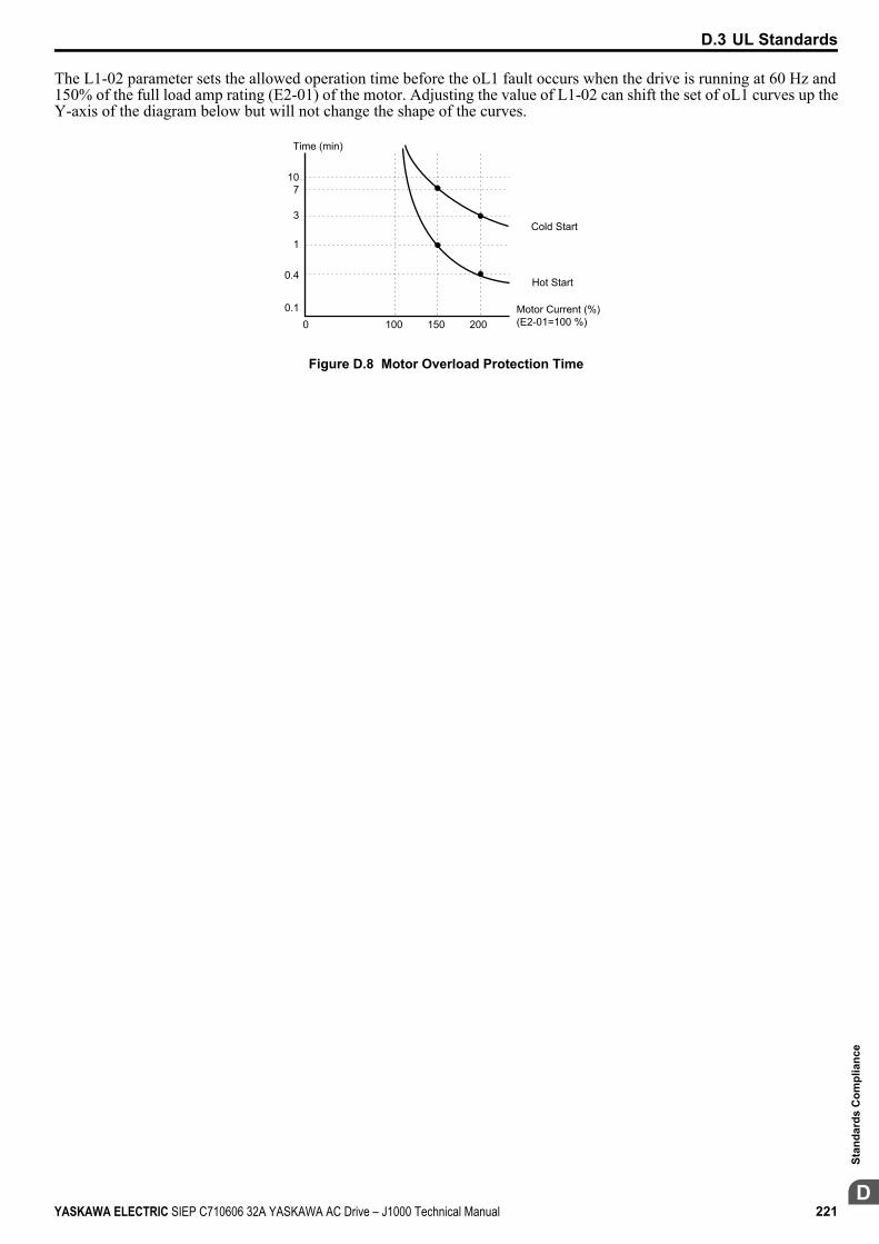
The L1-02 parameter sets the allowed operation time before the oL1 fault occurs when the drive is running at 60 Hz and150% of the full load amp rating (E2-01) of the motor. Adjusting the value of L1-02 can shift the set of oL1 curves up theY-axis of the diagram below but will not change the shape of the curves.
107
3
1
0.4
0.10 100 200150
Cold Start
Hot Start
Motor Current (%) (E2-01=100 %)
Time (min)
Figure D.8 Motor Overload Protection Time
D.3 UL Standards
YASKAWA ELECTRIC SIEP C710606 32A YASKAWA AC Drive – J1000 Technical Manual 221D
Stan
dard
s C
ompl
ianc
e
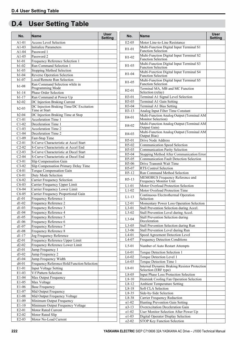
D.4 User Setting TableNo. Name User
SettingA1-01 Access Level Selection A1-03 Initialize Parameters A1-04 Password 1 A1-05 Password 2 b1-01 Frequency Reference Selection 1 b1-02 Run Command Selection 1 b1-03 Stopping Method Selection b1-04 Reverse Operation Selection b1-07 Local/Remote Run Selection
b1-08 Run Command Selection while inProgramming Mode
b1-14 Phase Order Selection b1-17 Run Command at Power Up b2-02 DC Injection Braking Current
b2-03 DC Injection Braking Time/DC ExcitationTime at Start
b2-04 DC Injection Braking Time at Stop C1-01 Acceleration Time 1 C1-02 Deceleration Time 1 C1-03 Acceleration Time 2 C1-04 Deceleration Time 2 C1-09 Fast-Stop Time C2-01 S-Curve Characteristic at Accel Start C2-02 S-Curve Characteristic at Accel End C2-03 S-Curve Characteristic at Decel Start C2-04 S-Curve Characteristic at Decel End C3-01 Slip Compensation Gain C3-02 Slip Compensation Primary Delay Time C4-01 Torque Compensation Gain C6-01 Duty Mode Selection C6-02 Carrier Frequency Selection C6-03 Carrier Frequency Upper Limit C6-04 Carrier Frequency Lower Limit C6-05 Carrier Frequency Proportional Gain d1-01 Frequency Reference 1 d1-02 Frequency Reference 2 d1-03 Frequency Reference 3 d1-04 Frequency Reference 4 d1-05 Frequency Reference 5 d1-06 Frequency Reference 6 d1-07 Frequency Reference 7 d1-08 Frequency Reference 8 d1-17 Jog Frequency Reference d2-01 Frequency Reference Upper Limit d2-02 Frequency Reference Lower Limit d3-01 Jump Frequency 1 d3-02 Jump Frequency 2 d3-04 Jump Frequency Width d4-01 Frequency Reference Hold Function Selection E1-01 Input Voltage Setting E1-03 V/f Pattern Selection E1-04 Max Output Frequency E1-05 Max Voltage E1-06 Base Frequency E1-07 Mid Output Frequency E1-08 Mid Output Frequency Voltage E1-09 Minimum Output Frequency E1-10 Minimum Output Frequency Voltage E2-01 Motor Rated Current E2-02 Motor Rated Slip E2-03 Motor No-Load Current
No. Name UserSetting
E2-05 Motor Line-to-Line Resistance
H1-01 Multi-Function Digital Input Terminal S1Function Selection
H1-02 Multi-Function Digital Input Terminal S2Function Selection
H1-03 Multi-Function Digital Input Terminal S3Function Selection
H1-04 Multi-Function Digital Input Terminal S4Function Selection
H1-05 Multi-Function Digital Input Terminal S5Function Selection
H2-01 Terminal MA, MB and MC FunctionSelection (relay)
H3-01 Terminal A1 Signal Level Selection H3-03 Terminal A1 Gain Setting H3-04 Terminal A1 Bias Setting H3-13 Analog Input Filter Time Constant
H4-01 Multi-Function Analog Output (Terminal AMMonitor Selection)
H4-02 Multi-Function Analog Output (Terminal AMOutput Gain)
H4-03 Multi-Function Analog Output (Terminal AMOutput Bias)
H5-01 Drive Node Address H5-02 Communication Speed Selection H5-03 Communication Parity Selection H5-04 Stopping Method After Communication Error H5-05 Communication Fault Detection Selection H5-06 Drive Transmit Wait Time H5-07 RTS Control Selection H5-12 Run Command Method Selection
H5-13 MEMOBUS Frequency Reference andFrequency Monitor Unit
L1-01 Motor Overload Protection Selection L1-02 Motor Overload Protection Time
L1-13 Continuous Electrothermal OperationSelection
L2-01 Momentary Power Loss Operation Selection L3-01 Stall Prevention Selection during Accel. L3-02 Stall Prevention Level during Accel.
L3-04 Stall Prevention Selection duringDeceleration
L3-05 Stall Prevention Selection during Run L3-06 Stall Prevention Level during Run L4-01 Speed Agreement Detection Level L4-07 Frequency Detection Conditions
L5-01 Number of Auto Restart Attempts
L6-01 Torque Detection Selection 1 L6-02 Torque Detection Level 1 L6-03 Torque Detection Time 1
L8-01 Internal Dynamic Braking Resistor ProtectionSelection (ERF type)
L8-05 Input Phase Loss Protection Selection L8-10 Heatsink Cooling Fan Operation Selection L8-12 Ambient Temperature Setting L8-18 Soft CLA Selection L8-35 Side-by-Side Selection L8-38 Carrier Frequency Reduction n1-02 Hunting Prevention Gain Setting n3-13 Overexcitation Deceleration Gain o1-02 User Monitor Selection After Power Up o1-03 Digital Operator Display Selection o2-02 STOP Key Function Selection
D.4 User Setting Table
222 YASKAWA ELECTRIC SIEP C710606 32A YASKAWA AC Drive – J1000 Technical Manual
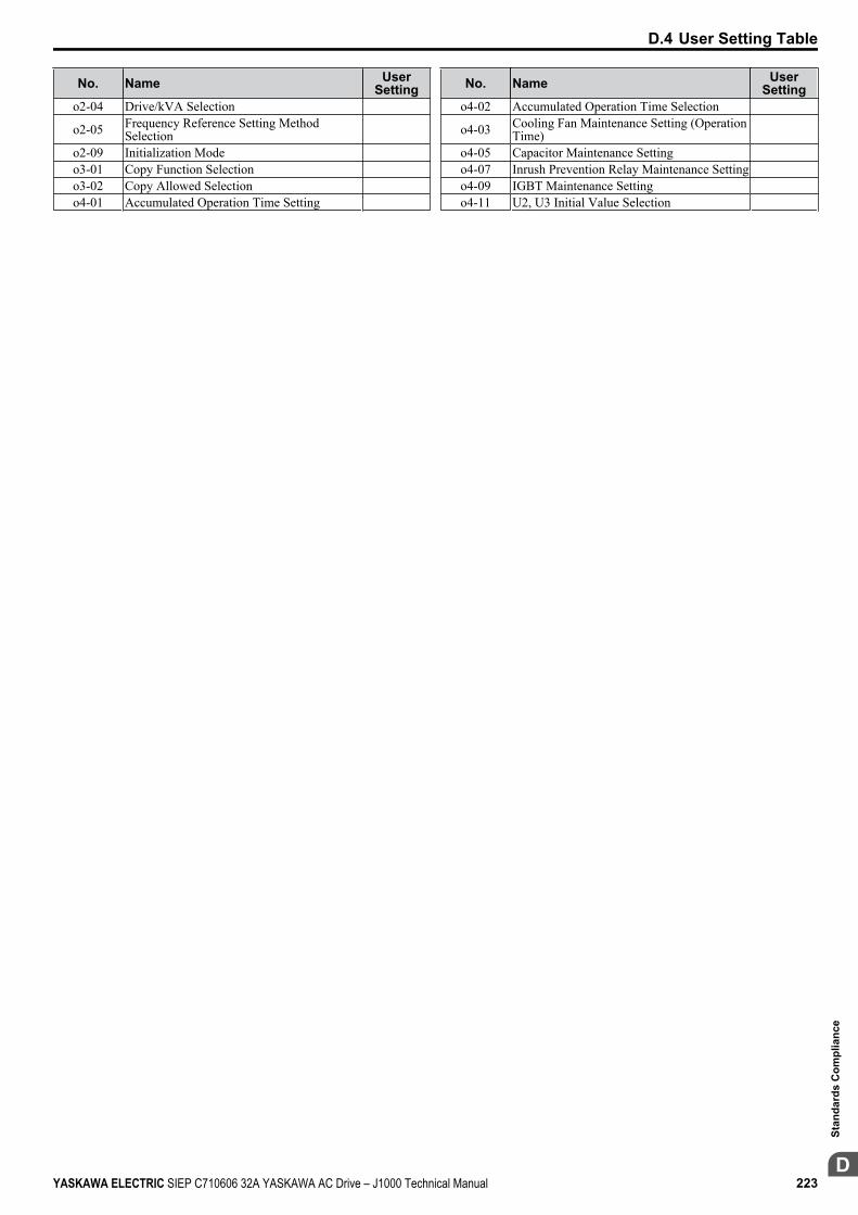
No. Name UserSetting
o2-04 Drive/kVA Selection
o2-05 Frequency Reference Setting MethodSelection
o2-09 Initialization Mode o3-01 Copy Function Selection o3-02 Copy Allowed Selection o4-01 Accumulated Operation Time Setting
No. Name UserSetting
o4-02 Accumulated Operation Time Selection
o4-03 Cooling Fan Maintenance Setting (OperationTime)
o4-05 Capacitor Maintenance Setting o4-07 Inrush Prevention Relay Maintenance Setting o4-09 IGBT Maintenance Setting o4-11 U2, U3 Initial Value Selection
D.4 User Setting Table
YASKAWA ELECTRIC SIEP C710606 32A YASKAWA AC Drive – J1000 Technical Manual 223D
Stan
dard
s C
ompl
ianc
e

D.4 User Setting Table
This Page Intentionally Blank
224 YASKAWA ELECTRIC SIEP C710606 32A YASKAWA AC Drive – J1000 Technical Manual
IndexNumerics3-Wire Sequence Example .. . . . . . . . . . . . . . . . . . . . . . . . . . . . . . . . . . . . . . . . . . . . .33
BBaseblock .. . . . . . . . . . . . . . . . . . . . . . . . . . . . . . . . . . . . . . . . . . . . . . . . . . . . . . . . . . . . . . . 131Baseblock Command (N.C.) .. . . . . . . . . . . . . . . . . . . . . . . . . . . . . . . . . . . . . . . . . 177Baseblock Command (N.O.) .. . . . . . . . . . . . . . . . . . . . . . . . . . . . . . . . . . . . . . . . . 177Base Frequency ... . . . . . . . . . . . . . . . . . . . . . . . . . . . . . . . . . . . . . . . . . . . . . . . . . . . . . . 127Braking Resistor .. . . . . . . . . . . . . . . . . . . . . . . . . . . . . . . . . . . . . . . . . . . . . . . . . . . . . . . . .47Braking Resistor, Installation .. . . . . . . . . . . . . . . . . . . . . . . . . . . . . . . . . . . . . . . . . .47Braking Resistor Overheat.. . . . . . . . . . . . . . . . . . . . . . . . . . . . . . . . . . . . . . . . . . . . 129Buzzing Sound from Motor at 2 kHz ... . . . . . . . . . . . . . . . . . . . . . . . . . . . . . 139
CC1-01 ... . . . . . . . . . . . . . . . . . . . . . . . . . . . . . . . . . . . . . . . . . . . . . . . . . . . . . . . . . . . . . .60, 140C1-01, -03, -05, -07.. . . . . . . . . . . . . . . . . . . . . . . . . . . . . . . . . . . . . . . . . . . . . . . . . . . . 127C1 Acceleration and Deceleration Times.. . . . . . . . . . . . . . . . . . . . . . . . . . . 174C2-01 ... . . . . . . . . . . . . . . . . . . . . . . . . . . . . . . . . . . . . . . . . . . . . . . . . . . . . . . . . . . . . . . . . . . 174C2-01 through C2-04... . . . . . . . . . . . . . . . . . . . . . . . . . . . . . . . . . . . . . . . . . . 122, 127C2-02 ... . . . . . . . . . . . . . . . . . . . . . . . . . . . . . . . . . . . . . . . . . . . . . . . . . . . . . . . . . . . . . . . . . . 174C2-03 ... . . . . . . . . . . . . . . . . . . . . . . . . . . . . . . . . . . . . . . . . . . . . . . . . . . . . . . . . . . . . . . . . . . 174C2-04 ... . . . . . . . . . . . . . . . . . . . . . . . . . . . . . . . . . . . . . . . . . . . . . . . . . . . . . . . . . . . . . . . . . . 174C2 S-Curve Characteristics.. . . . . . . . . . . . . . . . . . . . . . . . . . . . . . . . . . . . . . . . . . . 174C3-01 ... . . . . . . . . . . . . . . . . . . . . . . . . . . . . . . . . . . . . . . . . . . . . . . . . . . . . . . . . . . . . . . . . . . 122C3 Slip Compensation .. . . . . . . . . . . . . . . . . . . . . . . . . . . . . . . . . . . . . . . . . . . . . . . . 174C4-01 ... . . . . . . . . . . . . . . . . . . . . . . . . . . . . . . . . . . . . . . . . . . . . . . . . 122, 127, 128, 136C4 Torque Compensation.. . . . . . . . . . . . . . . . . . . . . . . . . . . . . . . . . . . . . . . . . . . . . 174C6-01 ... . . . . . . . . . . . . . . . . . . . . . . . . . . . . . . . . . . . . . . . . . . . . . . . . . . . . . . . . . . . . 122, 174C6-02 ... . . . . . . . . . . . . . . . . . . . . . . . . . .49, 122, 127, 128, 138, 139, 140, 175C6-03 ... . . . . . . . . . . . . . . . . . . . . . . . . . . . . . . . . . . . . . . . . . . . . . . . . . . . . . . . . . . . . . . . . . . 175C6-04 ... . . . . . . . . . . . . . . . . . . . . . . . . . . . . . . . . . . . . . . . . . . . . . . . . . . . . . . . . . . . . . . . . . . 175C6-05 ... . . . . . . . . . . . . . . . . . . . . . . . . . . . . . . . . . . . . . . . . . . . . . . . . . . . . . . . . . . . . 139, 175C6 Carrier Frequency ... . . . . . . . . . . . . . . . . . . . . . . . . . . . . . . . . . . . . . . . . . . . . . . . 174Cable Length Between Drive and Motor .. . . . . . . . . . . . . . . . . . . . . . . . . . . . .38CALL... . . . . . . . . . . . . . . . . . . . . . . . . . . . . . . . . . . . . . . . . . . . . . . . . . . . . . . . . . . . . 124, 131Cannot Change Parameter Settings.. . . . . . . . . . . . . . . . . . . . . . . . . . . . . . . . . . 136Can Not Reset . . . . . . . . . . . . . . . . . . . . . . . . . . . . . . . . . . . . . . . . . . . . . . . . . . . . . 124, 131Capacitor Maintenance Setting .. . . . . . . . . . . . . . . . . . . . . . . . . . . . . . . . . . . . . . 183Carrier Frequency Lower Limit. . . . . . . . . . . . . . . . . . . . . . . . . . . . . . . . . . . . . . . 175Carrier Frequency Proportional Gain .. . . . . . . . . . . . . . . . . . . . . . . . . . . . . . . 175Carrier Frequency Reduction.. . . . . . . . . . . . . . . . . . . . . . . . . . . . . . . . . . . . . . . . . 181Carrier Frequency Selection.. . . . . . . . . . . . . . . . . . . . . . . . . . . . . . . . . . . . 122, 175Carrier Frequency Setting Error .. . . . . . . . . . . . . . . . . . . . . . . . . . . . . . . 124, 134Carrier Frequency Upper Limit . . . . . . . . . . . . . . . . . . . . . . . . . . . . . . . . . . . . . . . 175CE... . . . . . . . . . . . . . . . . . . . . . . . . . . . . . . . . . . . . . . . . . . . . . . . . . . . . 123, 124, 125, 131CE mark.. . . . . . . . . . . . . . . . . . . . . . . . . . . . . . . . . . . . . . . . . . . . . . . . . . . . . . . . . . . . . . . . . 214CoF ... . . . . . . . . . . . . . . . . . . . . . . . . . . . . . . . . . . . . . . . . . . . . . . . . . . . . . . . . . . . . . . 123, 125Comm. Fault Detection Selection .. . . . . . . . . . . . . . . . . . . . . . . . . . . . . . . . . . . 179Communication Parity Selection .. . . . . . . . . . . . . . . . . . . . . . . . . . . . . . . . . . . . 179Communication Speed Selection .. . . . . . . . . . . . . . . . . . . . . . . . . . . . . . . . . . . . 179
Communications Test Mode ... . . . . . . . . . . . . . . . . . . . . . . . . . . . . . . . . . . . . . . . 178Connected Machinery Vibrates When Motor Rotates .. . . . . . . . . . . . 139Control Circuit Fault . . . . . . . . . . . . . . . . . . . . . . . . . . . . . . . . . . . . . . . . . . . . . . . . . . . 123Control Circuit Input Terminals .. . . . . . . . . . . . . . . . . . . . . . . . . . . . . . . . . . . . . . .40Control Circuit Terminal Block Functions .. . . . . . . . . . . . . . . . . . . . . . . . . . .40Control Circuit Terminal Configuration .. . . . . . . . . . . . . . . . . . . . . . . . . . . . . .41Cooling Fan Maintenance Setting (Operation Time) .. . . . . . . . . . . . . 183Cooling Fan Replacement .. . . . . . . . . . . . . . . . . . . . . . . . . . . . . . . . . . . . . . . . . . . . 132CPF02 ... . . . . . . . . . . . . . . . . . . . . . . . . . . . . . . . . . . . . . . . . . . . . . . . . . . . . . . . . . . . . . . . . . 125CPF06 ... . . . . . . . . . . . . . . . . . . . . . . . . . . . . . . . . . . . . . . . . . . . . . . . . . . . . . . . . . . . . . . . . . 125CPF08 ... . . . . . . . . . . . . . . . . . . . . . . . . . . . . . . . . . . . . . . . . . . . . . . . . . . . . . . . . . . . . . . . . . 125CPF20 ... . . . . . . . . . . . . . . . . . . . . . . . . . . . . . . . . . . . . . . . . . . . . . . . . . . . . . . . . . . . 123, 125CPF21 ... . . . . . . . . . . . . . . . . . . . . . . . . . . . . . . . . . . . . . . . . . . . . . . . . . . . . . . . . . . . 123, 125CPF22 ... . . . . . . . . . . . . . . . . . . . . . . . . . . . . . . . . . . . . . . . . . . . . . . . . . . . . . . . . . . . 123, 126CPF23 ... . . . . . . . . . . . . . . . . . . . . . . . . . . . . . . . . . . . . . . . . . . . . . . . . . . . . . . . . . . . 123, 126CPF24 ... . . . . . . . . . . . . . . . . . . . . . . . . . . . . . . . . . . . . . . . . . . . . . . . . . . . . . . . . . . . 123, 126CrST ... . . . . . . . . . . . . . . . . . . . . . . . . . . . . . . . . . . . . . . . . . . . . . . . . . . . . . . . . . . . . . 124, 131C Tuning ... . . . . . . . . . . . . . . . . . . . . . . . . . . . . . . . . . . . . . . . . . . . . . . . . . . . . . . . . . . . . . . 174Current Offset Fault . . . . . . . . . . . . . . . . . . . . . . . . . . . . . . . . . . . . . . . . . . . . . . 123, 125
Drive Motor Overload Protection.. . . . . . . . . . . . . . . . . . . . . . . . . . . . . . . . . . . 220 Drive Short-Circuit Rating.. . . . . . . . . . . . . . . . . . . . . . . . . . . . . . . . . . . . . . . . . . . 220 European Standards.. . . . . . . . . . . . . . . . . . . . . . . . . . . . . . . . . . . . . . . . . . . . . . . . . . . . .14 Low Voltage Wiring.. . . . . . . . . . . . . . . . . . . . . . . . . . . . . . . . . . . . . . . . . . . . . . . . . . 220 UL Standards .. . . . . . . . . . . . . . . . . . . . . . . . . . . . . . . . . . . . . . . . . . . . . . . . . . . . . . . . . . . .14
GGeneral Safety Information.. . . . . . . . . . . . . . . . . . . . . . . . . . . . . . . . . . . . . . . . . . . . .11Ground Fault Interrupter Activates When Drive is Running .. . . . 140Ground Wiring .. . . . . . . . . . . . . . . . . . . . . . . . . . . . . . . . . . . . . . . . . . . . . . . . . . . . . . . . . . .38
HH1-01 ... . . . . . . . . . . . . . . . . . . . . . . . . . . . . . . . . . . . . . . . . . . . . . . . . . . . . . . . . . . . . . . . . . . 177H1-02 ... . . . . . . . . . . . . . . . . . . . . . . . . . . . . . . . . . . . . . . . . . . . . . . . . . . . . . . . . . . . . . . . . . . 177H1-03 ... . . . . . . . . . . . . . . . . . . . . . . . . . . . . . . . . . . . . . . . . . . . . . . . . . . . . . . . . . . . . . . . . . . 177H1-04 ... . . . . . . . . . . . . . . . . . . . . . . . . . . . . . . . . . . . . . . . . . . . . . . . . . . . . . . . . . . . . . . . . . . 177H1-05 ... . . . . . . . . . . . . . . . . . . . . . . . . . . . . . . . . . . . . . . . . . . . . . . . . . . . . . . . . . . . . . .33, 177H1 Multi-Function Digital Input.. . . . . . . . . . . . . . . . . . . . . . . . . . . . . . . . . . . . . 177H1 Multi-Function Digital Input Selections.. . . . . . . . . . . . . . . . . . . . . . . . 177H2 Multi-Function Digital Outputs .. . . . . . . . . . . . . . . . . . . . . . . . . . . . . . . . . 178H2 Multi-Function Digital Output Settings .. . . . . . . . . . . . . . . . . . . . . . . . 178H3-01 ... . . . . . . . . . . . . . . . . . . . . . . . . . . . . . . . . . . . . . . . . . . . . . . . . . . . . . . . .46, 136, 178H3-01 Details. . . . . . . . . . . . . . . . . . . . . . . . . . . . . . . . . . . . . . . . . . . . . . . . . . . . . . . . . . . . . .46H3-13 ... . . . . . . . . . . . . . . . . . . . . . . . . . . . . . . . . . . . . . . . . . . . . . . . . . . . . . . . . . . . . 122, 139H3 Analog Input A1... . . . . . . . . . . . . . . . . . . . . . . . . . . . . . . . . . . . . . . . . . . . . . . . . . 178H4 Multi-Function Analog Output AM.... . . . . . . . . . . . . . . . . . . . . . . . . . . 179H5-01 ... . . . . . . . . . . . . . . . . . . . . . . . . . . . . . . . . . . . . . . . . . . . . . . . . . . . . . . . . . . . . . . . . . . 179H5-02 ... . . . . . . . . . . . . . . . . . . . . . . . . . . . . . . . . . . . . . . . . . . . . . . . . . . . . . . . . . . . . . . . . . . 179H5-03 ... . . . . . . . . . . . . . . . . . . . . . . . . . . . . . . . . . . . . . . . . . . . . . . . . . . . . . . . . . . . . . . . . . . 179H5-04 ... . . . . . . . . . . . . . . . . . . . . . . . . . . . . . . . . . . . . . . . . . . . . . . . . . . . . . . . . . . . . 126, 179H5-05 ... . . . . . . . . . . . . . . . . . . . . . . . . . . . . . . . . . . . . . . . . . . . . . . . . . . . . . . . . . . . . . . . . . . 179
YASKAWA ELECTRIC SIEP C710606 32A YASKAWA AC Drive – J1000 Technical Manual 225
H5-06 ... . . . . . . . . . . . . . . . . . . . . . . . . . . . . . . . . . . . . . . . . . . . . . . . . . . . . . . . . . . . . . . . . . . . . . . . 179H5-07 ... . . . . . . . . . . . . . . . . . . . . . . . . . . . . . . . . . . . . . . . . . . . . . . . . . . . . . . . . . . . . . . . . . . . . . . . 179H5-12 ... . . . . . . . . . . . . . . . . . . . . . . . . . . . . . . . . . . . . . . . . . . . . . . . . . . . . . . . . . . . . . . . . . . . . . . . 179H5-13 ... . . . . . . . . . . . . . . . . . . . . . . . . . . . . . . . . . . . . . . . . . . . . . . . . . . . . . . . . . . . . . . . . . . . . . . . 179H5 MEMOBUS/Modbus Communications .. . . . . . . . . . . . . . . . . . . . . . . . . . . . . 179Heatsink Cooling Fan Operation Selection.. . . . . . . . . . . . . . . . . . . . . . . . . . . . . . 181Heavy Duty Ratings .. . . . . . . . . . . . . . . . . . . . . . . . . . . . . . . . . . . . . . . . . . . . . . . . . . . . . . . . 164Hunting Prevention Gain .. . . . . . . . . . . . . . . . . . . . . . . . . . . . . . . . . . . . . . . . . . . . . . . . . . 122
II/O Connections.. . . . . . . . . . . . . . . . . . . . . . . . . . . . . . . . . . . . . . . . . . . . . . . . . . . . . . . . . . . . . . . 32IGBT Maintenance Setting .. . . . . . . . . . . . . . . . . . . . . . . . . . . . . . . . . . . . . . . . . . . . . . . . 183Input Phase Loss .. . . . . . . . . . . . . . . . . . . . . . . . . . . . . . . . . . . . . . . . . . . . . . . . . . . . . . 123, 129Input Terminals .. . . . . . . . . . . . . . . . . . . . . . . . . . . . . . . . . . . . . . . . . . . . . . . . . . . . . . . . . . . . . . . 60Input Voltage Setting.. . . . . . . . . . . . . . . . . . . . . . . . . . . . . . . . . . . . . . . . . . . . . . . . . . . . . . . 176Inrush Prevention Circuit Fault . . . . . . . . . . . . . . . . . . . . . . . . . . . . . . . . . . . . . . . . . . . . 129Inrush Prevention Relay Maintenance Setting .. . . . . . . . . . . . . . . . . . . . . . . . . . 183Inspection .. . . . . . . . . . . . . . . . . . . . . . . . . . . . . . . . . . . . . . . . . . . . . . . . . . . . . . . . . . . . . . 144, 145Installation Environment.. . . . . . . . . . . . . . . . . . . . . . . . . . . . . . . . . . . . . . . . . . . . . . . . . . . . . 26Installation Orientation.. . . . . . . . . . . . . . . . . . . . . . . . . . . . . . . . . . . . . . . . . . . . . . . . . . . . . . . 27Installing Multiple Drives .. . . . . . . . . . . . . . . . . . . . . . . . . . . . . . . . . . . . . . . . . . . . . . . . . . . 27Internal Dynamic Braking Resistor Protection Selection (ERF type).. . . . . . . . . . . . . . . . . . . . . . . . . . . . . . . . . . . . . . . . . . . . . . . . . . . . . . . . . . . . . . . . . . . . . . . . . . . . . . . . . 181
JJog Frequency Reference .. . . . . . . . . . . . . . . . . . . . . . . . . . . . . . . . . . . . . . . . . . . . . . . . . . 175Jog Reference Selection.. . . . . . . . . . . . . . . . . . . . . . . . . . . . . . . . . . . . . . . . . . . . . . . . . . . . 177Jump Frequency... . . . . . . . . . . . . . . . . . . . . . . . . . . . . . . . . . . . . . . . . . . . . . . . . . . . . . . . . . . . 122Jump Frequency 1 .. . . . . . . . . . . . . . . . . . . . . . . . . . . . . . . . . . . . . . . . . . . . . . . . . . . . . . . . . . 176Jump Frequency 2 .. . . . . . . . . . . . . . . . . . . . . . . . . . . . . . . . . . . . . . . . . . . . . . . . . . . . . . . . . . 176Jump Frequency Width .. . . . . . . . . . . . . . . . . . . . . . . . . . . . . . . . . . . . . . . . . . . . . . . . . . . . 176
MMagnetic Flux Compensation Capacity .. . . . . . . . . . . . . . . . . . . . . . . . . . . . . . . . . 174Main Circuit Connection Diagram ... . . . . . . . . . . . . . . . . . . . . . . . . . . . . . . . . . . 34, 39Main Circuit Terminal Functions.. . . . . . . . . . . . . . . . . . . . . . . . . . . . . . . . . . . . . . . . . . . 37Main Circuit Terminal Power Supply.. . . . . . . . . . . . . . . . . . . . . . . . . . . . . . . . . . . . . . 38Main Circuit Terminal Wiring .. . . . . . . . . . . . . . . . . . . . . . . . . . . . . . . . . . . . . . . . 21, 219Main Frequency Reference .. . . . . . . . . . . . . . . . . . . . . . . . . . . . . . . . . . . . . . . . . . . . . . . . . . 46Maintenance .. . . . . . . . . . . . . . . . . . . . . . . . . . . . . . . . . . . . . . . . . . . . . . . . . . . . . . . . . . . . . . . . . 146Master Speed Reference Lower Limit . . . . . . . . . . . . . . . . . . . . . . . . . . . . . . . . . . . . 175Max Output Frequency... . . . . . . . . . . . . . . . . . . . . . . . . . . . . . . . . . . . . . . . . . . . . . . . . . . . 176MEMOBUS/Modbus Communication Error.. . . . . . . . . . 123, 124, 125, 131MEMOBUS/Modbus Communications Test Mode Complete .. . . . . . . 132MEMOBUS/Modbus Communications Test Mode Error.. . . . . . . . . . . . . 133MEMOBUS/Modbus Error Code .. . . . . . . . . . . . . . . . . . . . . . . . . . . . . . . . . . . . . . . . 184MEMOBUS/Modbus Test Mode Complete.. . . . . . . . . . . . . . . . . . . . . . . . . . . . . 124Mid Output Voltage A ... . . . . . . . . . . . . . . . . . . . . . . . . . . . . . . . . . . . . . . . . . . . . . . . . . . . 122Minimum Output Frequency ... . . . . . . . . . . . . . . . . . . . . . . . . . . . . . . . . . . . . . . 139, 140Minimum Output Voltage .. . . . . . . . . . . . . . . . . . . . . . . . . . . . . . . . . . . . . . . . . . . . . . . . . 122Minor Alarms ... . . . . . . . . . . . . . . . . . . . . . . . . . . . . . . . . . . . . . . . . . . . . . . . . . . . . . . . . . . . . . 123Minor Faults . . . . . . . . . . . . . . . . . . . . . . . . . . . . . . . . . . . . . . . . . . . . . . . . . . . . . . . . . . . . . . . . . . 123Modes .. . . . . . . . . . . . . . . . . . . . . . . . . . . . . . . . . . . . . . . . . . . . . . . . . . . . . . . . . . . . . . . . . . . . . . . . . . 57Momentary Power Loss Operation Selection .. . . . . . . . . . . . . . . . . . . . . . . . . . . 180Motor Does Not Operate When an External Run Command is Input.. . . . . . . . . . . . . . . . . . . . . . . . . . . . . . . . . . . . . . . . . . . . . . . . . . . . . . . . . . . . . . . . . . . . . . . . . . . . . . . . . 140Motor Does Not Operate When the RUN Button on the Digital Operator is Pressed.. . . . . . . . . . . . . . . . . . . . . . . . . . . . . . . . . . . . . . . . . . . . . . . . . . . . . . . . . . . . . . . . . . . . . 139Motor Does Not Rotate .. . . . . . . . . . . . . . . . . . . . . . . . . . . . . . . . . . . . . . . . . . . . . . . . . . . . 136Motor Hunting and Oscillation Control Parameters .. . . . . . . . . . . . . . . . . . . 122Motor Hunting Occurs When Operating With a Light Load... . . . . . . . . 138Motor is Too Hot .. . . . . . . . . . . . . . . . . . . . . . . . . . . . . . . . . . . . . . . . . . . . . . . . . . . . . . . . . . . 137Motor Overload .. . . . . . . . . . . . . . . . . . . . . . . . . . . . . . . . . . . . . . . . . . . . . . . . . . . . . . . 123, 127Motor Protection Function.. . . . . . . . . . . . . . . . . . . . . . . . . . . . . . . . . . . . . . . . . . . . . . . . . 127
Motor Rotates After the Drive Output is Shut Off .. . . . . . . . . . . . . . . . . . . . . 139Motor Rotates Faster Than the Frequency Reference.. . . . . . . . . . . . . . . . . . 138Motor Rotates in One Direction Only.. . . . . . . . . . . . . . . . . . . . . . . . . . . . . . 137, 140Motor Stalls During Acceleration or With Large Loads .. . . . . . . . . . . . . . 137Motor Stops During Acceleration or When a Load is Connected.. . . . 140Motor Wiring.. . . . . . . . . . . . . . . . . . . . . . . . . . . . . . . . . . . . . . . . . . . . . . . . . . . . . . . . . . . . . . . . . . 38Multi-Function Analog 1 (Terminal AM Monitor Selection).. . . . . . . . . 179Multi-Function Digital Input Terminal S1 Function Selection .. . . . . . . 177Multi-Function Digital Input Terminal S2 Function Selection .. . . . . . . 177Multi-Function Digital Input Terminal S3 Function Selection .. . . . . . . 177Multi-Function Digital Input Terminal S4 Function Selection .. . . . . . . 177Multi-Function Digital Input Terminal S5 Function Selection .. . . . . . . 177Multi-Function Input Selection Error .. . . . . . . . . . . . . . . . . . . . . . . . . . . . . . . . . . . . 134Multi-Function Input Setting Error.. . . . . . . . . . . . . . . . . . . . . . . . . . . . . . . . . . . . . . . 124Multi-Step Speed Reference.. . . . . . . . . . . . . . . . . . . . . . . . . . . . . . . . . . . . . . . . . . . . . . . 177
PParameter Range Setting Error.. . . . . . . . . . . . . . . . . . . . . . . . . . . . . . . . . . . . . . . . . . . . 134Parameter Setting Range Error.. . . . . . . . . . . . . . . . . . . . . . . . . . . . . . . . . . . . . . . . . . . . 124Parameter Settings .. . . . . . . . . . . . . . . . . . . . . . . . . . . . . . . . . . . . . . . . . . . . . . . . . . . . . . . . . . . . 59PASS ... . . . . . . . . . . . . . . . . . . . . . . . . . . . . . . . . . . . . . . . . . . . . . . . . . . . . . . . . . . . . . . . . . 124, 132Password 1.. . . . . . . . . . . . . . . . . . . . . . . . . . . . . . . . . . . . . . . . . . . . . . . . . . . . . . . . . . . . . . . . . . . 173Password 2.. . . . . . . . . . . . . . . . . . . . . . . . . . . . . . . . . . . . . . . . . . . . . . . . . . . . . . . . . . . . . . . . . . . 173Password Settings.. . . . . . . . . . . . . . . . . . . . . . . . . . . . . . . . . . . . . . . . . . . . . . . . . . . . . . . . . . . . . 66Performance Life .. . . . . . . . . . . . . . . . . . . . . . . . . . . . . . . . . . . . . . . . . . . . . . . . . . . . . . . . . . . 146Peripheral Devices Affected by Drive Operation .. . . . . . . . . . . . . . . . . . . . . . 140PF ... . . . . . . . . . . . . . . . . . . . . . . . . . . . . . . . . . . . . . . . . . . . . . . . . . . . . . . . . . . . . . . . . . . . . . 123, 129Phase Order Selection .. . . . . . . . . . . . . . . . . . . . . . . . . . . . . . . . . . . . . . . . . . . . . . . . . . . . . . 173Poor Speed Control Accuracy.. . . . . . . . . . . . . . . . . . . . . . . . . . . . . . . . . . . . . . . . . . . . . 138Programming Mode ... . . . . . . . . . . . . . . . . . . . . . . . . . . . . . . . . . . . . . . . . . . . . . . . . . . . 57, 58Protective Covers, Removing ... . . . . . . . . . . . . . . . . . . . . . . . . . . . . . . . . . . . . . . . 36, 160PWM Feedback Data Fault. . . . . . . . . . . . . . . . . . . . . . . . . . . . . . . . . . . . . . . . . . . . . . . . . 123PWM Feedback Fault . . . . . . . . . . . . . . . . . . . . . . . . . . . . . . . . . . . . . . . . . . . . . . . . . . . . . . . 126
RRAM Fault. . . . . . . . . . . . . . . . . . . . . . . . . . . . . . . . . . . . . . . . . . . . . . . . . . . . . . . . . . . . . . 123, 125REMOTE ... . . . . . . . . . . . . . . . . . . . . . . . . . . . . . . . . . . . . . . . . . . . . . . . . . . . . . . . . . . . . . . . . . . . . 60Replacement Parts . . . . . . . . . . . . . . . . . . . . . . . . . . . . . . . . . . . . . . . . . . . . . . . . . . . . . 146, 170Restart Enabled .. . . . . . . . . . . . . . . . . . . . . . . . . . . . . . . . . . . . . . . . . . . . . . . . . . . . . . . . . . . . . 178Reverse Direction.. . . . . . . . . . . . . . . . . . . . . . . . . . . . . . . . . . . . . . . . . . . . . . . . . . . . . . . . . . . 178Reverse Operation Selection .. . . . . . . . . . . . . . . . . . . . . . . . . . . . . . . . . . . . . . . . . . . . . . 173Reverse Run Command (2-Wire sequence) .. . . . . . . . . . . . . . . . . . . . . . . . . . . . . 178RTS Control Selection .. . . . . . . . . . . . . . . . . . . . . . . . . . . . . . . . . . . . . . . . . . . . . . . . . . . . . 179Run Command/Frequency Reference Source Selection Error.. . . . . . . . 134Run Command at Power Up... . . . . . . . . . . . . . . . . . . . . . . . . . . . . . . . . . . . . . . . . . . . . . 173Run Command Input Error .. . . . . . . . . . . . . . . . . . . . . . . . . . . . . . . . . . . . . . . . . . . . . . . . 124Run Command Selection .. . . . . . . . . . . . . . . . . . . . . . . . . . . . . . . . . . . . . . . . . . . . 136, 173Run Command Selection during Program... . . . . . . . . . . . . . . . . . . . . . . . . . . . . . 173Run Command Selection Error .. . . . . . . . . . . . . . . . . . . . . . . . . . . . . . . . . . . . . . . . . . . 124
SSafety Hazard Definitions .. . . . . . . . . . . . . . . . . . . . . . . . . . . . . . . . . . . . . . . . . . . . . . . . . . . 11Safety Information.. . . . . . . . . . . . . . . . . . . . . . . . . . . . . . . . . . . . . . . . . . . . . . . . . . . . . . . . . . . . 11S-Curve Characteristic at Accel End ... . . . . . . . . . . . . . . . . . . . . . . . . . . . . . . . . . . . 174S-Curve Characteristic at Accel Start . . . . . . . . . . . . . . . . . . . . . . . . . . . . . . . . . . . . . 174S-Curve Characteristic at Decel End ... . . . . . . . . . . . . . . . . . . . . . . . . . . . . . . . . . . . 174S-Curve Characteristic at Decel Start . . . . . . . . . . . . . . . . . . . . . . . . . . . . . . . . . . . . . 174SE ... . . . . . . . . . . . . . . . . . . . . . . . . . . . . . . . . . . . . . . . . . . . . . . . . . . . . . . . . . . . . . . . . . . . . . 124, 133Serial Communication Reference Selection.. . . . . . . . . . . . . . . . . . . . . . . . . . . . . 177Serial Communication Transmission Error .. . . . . . . . . . . . . . . . . . . . . . . 124, 131Setup Mode ... . . . . . . . . . . . . . . . . . . . . . . . . . . . . . . . . . . . . . . . . . . . . . . . . . . . . . . . . . . . . . 58, 60Sinking/Sourcing Mode Switch.. . . . . . . . . . . . . . . . . . . . . . . . . . . . . . . . . . . . . . . . . . . . . 21Slip Compensation Gain .. . . . . . . . . . . . . . . . . . . . . . . . . . . . . . . . . . . . . . . . . . . . . . . . . . . 174
Index
226 YASKAWA ELECTRIC SIEP C710606 32A YASKAWA AC Drive – J1000 Technical Manual
Slip Compensation Primary Delay Time ... . . . . . . . . . . . . . . . . . . . . . . . . . . . . . . 174Soft Charge Circuit Fault . . . . . . . . . . . . . . . . . . . . . . . . . . . . . . . . . . . . . . . . . . . . . . . . . . . 124Soft CLA Selection .. . . . . . . . . . . . . . . . . . . . . . . . . . . . . . . . . . . . . . . . . . . . . . . . . . . . . . . . . 181Software No. (Flash) .. . . . . . . . . . . . . . . . . . . . . . . . . . . . . . . . . . . . . . . . . . . . . . . . . . . . . . . 184Software No. (ROM) ... . . . . . . . . . . . . . . . . . . . . . . . . . . . . . . . . . . . . . . . . . . . . . . . . . . . . . 184Speed Agreement Detection Level .. . . . . . . . . . . . . . . . . . . . . . . . . . . . . . . . . . . . . . . 180Speed Search .. . . . . . . . . . . . . . . . . . . . . . . . . . . . . . . . . . . . . . . . . . . . . . . . . . . . . . . . . . . . . . . . 178Stall Prevention .. . . . . . . . . . . . . . . . . . . . . . . . . . . . . . . . . . . . . . . . . . . . . . . . . . . . . . . . . . . . . 122Stall Prevention Level during Acceleration .. . . . . . . . . . . . . . . . . . . . . . . . . . . . . 180Stall Prevention Level during Run ... . . . . . . . . . . . . . . . . . . . . . . . . . . . . . . . . . . . . . 180Stall Prevention Selection during Acceleration.. . . . . . . . . . . . . . . . . . . . . . . . . 180Stall Prevention Selection during Deceleration.. . . . . . . . . . . . . . . . . . . . . . . . . 180Stall Prevention Selection during Run ... . . . . . . . . . . . . . . . . . . . . . . . . . . . . . . . . . 180Standard Connection Diagram ... . . . . . . . . . . . . . . . . . . . . . . . . . . . . . . . . . . . . . . . . . . . . 32STOP Key Function Selection .. . . . . . . . . . . . . . . . . . . . . . . . . . . . . . . . . . . . . . . . . . . . 182Stopping Method After Communication Error .. . . . . . . . . . . . . . . . . . . . . . . . . 179
TTerminal A1 Bias Setting.. . . . . . . . . . . . . . . . . . . . . . . . . . . . . . . . . . . . . . . . . . . . . . . . . . 178Terminal A1 Gain Setting .. . . . . . . . . . . . . . . . . . . . . . . . . . . . . . . . . . . . . . . . . . . . . . . . . 178Terminal A1 Signal Level Selection .. . . . . . . . . . . . . . . . . . . . . . . . . . . . . . . . . . . . . 178Terminal Block Configuration .. . . . . . . . . . . . . . . . . . . . . . . . . . . . . . . . . . . . . . . . . . . . . . 35Test Run... . . . . . . . . . . . . . . . . . . . . . . . . . . . . . . . . . . . . . . . . . . . . . . . . . . . . . . . . . . . . . . . . . . . . . . 64Tightening Torque .. . . . . . . . . . . . . . . . . . . . . . . . . . . . . . . . . . . . . . . . . . . . . . . . . . . . . . . . . . . . 37Timing Fault. . . . . . . . . . . . . . . . . . . . . . . . . . . . . . . . . . . . . . . . . . . . . . . . . . . . . . . . . . . . . . . . . . 123Torque Compensation Gain .. . . . . . . . . . . . . . . . . . . . . . . . . . . . . . . . . . . . . . . . . 122, 174Torque Detection 1 (N.O.).. . . . . . . . . . . . . . . . . . . . . . . . . . . . . . . . . . . . . . . . . . . . . . . . . 178Torque Detection 2 (N.O.).. . . . . . . . . . . . . . . . . . . . . . . . . . . . . . . . . . . . . . . . . . . . . . . . . 178Torque Detection Level 1.. . . . . . . . . . . . . . . . . . . . . . . . . . . . . . . . . . . . . . . . . . . . . . . . . . 181Torque Detection Selection 1 .. . . . . . . . . . . . . . . . . . . . . . . . . . . . . . . . . . . . . . . . . . . . . 181Torque Detection Time 1 .. . . . . . . . . . . . . . . . . . . . . . . . . . . . . . . . . . . . . . . . . . . . . . . . . . 181Transistor Input Signal .. . . . . . . . . . . . . . . . . . . . . . . . . . . . . . . . . . . . . . . . . . . . . . . . . . . . . . . 44
VV/f Data Setting Error.. . . . . . . . . . . . . . . . . . . . . . . . . . . . . . . . . . . . . . . . . . . . . . . . 124, 134Verify Menu ... . . . . . . . . . . . . . . . . . . . . . . . . . . . . . . . . . . . . . . . . . . . . . . . . . . . . . . . . . . . . . . . . . 58
WWire Gauges.. . . . . . . . . . . . . . . . . . . . . . . . . . . . . . . . . . . . . . . . . . . . . . . . . . . . . . . . . . . . . . . . . . . 37Wiring Checklist . . . . . . . . . . . . . . . . . . . . . . . . . . . . . . . . . . . . . . . . . . . . . . . . . . . . . . . . . . . . . . . 49Wiring Procedure .. . . . . . . . . . . . . . . . . . . . . . . . . . . . . . . . . . . . . . . . . . . . . . . . . . . . . . . . . . . . . 42
ZZero Speed... . . . . . . . . . . . . . . . . . . . . . . . . . . . . . . . . . . . . . . . . . . . . . . . . . . . . . . . . . . . . . . . . . 178
Index
YASKAWA ELECTRIC SIEP C710606 32A YASKAWA AC Drive – J1000 Technical Manual 227

Index
This Page Intentionally Blank
228 YASKAWA ELECTRIC SIEP C710606 32A YASKAWA AC Drive – J1000 Technical Manual

This Page Intentionally Blank
YASKAWA ELECTRIC SIEP C710606 32A YASKAWA AC Drive – J1000 Technical Manual 229

YASKAWA AC Drive – J1000Compact V/f Control DriveTechnical ManualYASKAWA ELECTRIC AMERICA, INC.2121 Norman Drive South, Waukegan, IL 60085, U.S.A.Phone: (800) YASKAWA (800-927-5292) or 1-847-887-7000 Fax: 1-847-887-7370http://www.yaskawa.comYASKAWA ELECTRIC AMERICA, INC.Drives Division,16555 W. Ryerson Rd., New Berlin, WI 53151, U.S.A.Phone: (800) YASKAWA (800-927-5292) Fax: (262) 782-3418http://www.yaskawa.comYASKAWA ELÉTRICO DO BRASIL COMÉRCIO LTDA.Avenda Fagundes Filho, 620 Bairro Saude, São Paulo,SP04304–000, BrasilPhone: 55-11-3585-1100 Fax: 55-11-5581-8795http://www.yaskawa.com.brYASKAWA ELECTRIC CORPORATIONNew Pier Takeshiba South Tower, 1-16-1, Kaigan, Minatoku, Tokyo, Japan 105-022,Phone: 81-3-5402-4511 Fax: 81-3-5402-4580http://www.yaskawa.co.jpIRUMA BUSINESS CENTER (SOLUTION CENTER)480, Kamifujisawa, Iruma,Saitama 358–8555, JapanPhone: 81-4-2962-5696 Fax: 81-4-2962-6138YASKAWA ELECTRIC EUROPE GmbHAm Kronberger Hang 2, Schwalbach, 65824, GermanyPhone: 49-6196-569-300 Fax: 49-6196-569-312
YASKAWA ELECTRIC CORPORATION
In the event that the end user of this product is to be the military and said product is to be employed in any weapons systems or the manufacture thereof, the export will fall under the relevant regulations as stipulated in the Foreign Exchange and Foreign TradeRegulations. Therefore, be sure to follow all procedures and submit all relevant documentation according to any and all rules, regulations and laws that may apply.Specifications are subject to change without notice for ongoing product modifications and improvements.
© 2008 YASKAWA ELECTRIC CORPORATION. All rights reserved.
Manual No. SIEP C710606 32A