Yamaha xt 125 service manual
279
2006 XT125R(V) XT125X(V) SERVICE MANUAL 3D6-F8197-E0
-
Upload
george-petre -
Category
Documents
-
view
4.257 -
download
1.460
Transcript of Yamaha xt 125 service manual
7/22/2019 Yamaha xt 125 service manual
http://slidepdf.com/reader/full/yamaha-xt-125-service-manual 1/279
2006
XT125R(V)XT125X(V)
SERVICE MANUAL
3D6-F8197-E0
7/22/2019 Yamaha xt 125 service manual
http://slidepdf.com/reader/full/yamaha-xt-125-service-manual 2/279
XT125R(V)/XT125X(V) 2006SERVICE MANUAL
©2005 by Yamaha Motor Europe N.V.
First edition, 2006
All rights reserved.
Any reprinting or unauthorized use
without the written permission of
Yamaha Motor Europe N.V. is
expressly prohibited.

7/22/2019 Yamaha xt 125 service manual
http://slidepdf.com/reader/full/yamaha-xt-125-service-manual 3/279
WARNINGThis manual was written by Yamaha Motor Europe N.V. primarily for use by Yamaha dealers and
their qualified mechanics. It is not possible to provide a mechanic with all necessary information with
only one manual. For this reason, persons using this book to perform maintenance and repairs on
Yamaha motorcycles should have a basic understanding of the mechanical concepts and proce-dures concerning motorcycle repair technology. Without such knowledge, attempted repairs or ser-
vice to the motorcycle may render it unfit to use and/or unsafe.
Yamaha Motor Europe N.V. is continuously striving to improve all models manufactured by
Yamaha. Modifications and significant changes in specifications or procedures will be forwarded to
all authorized Yamaha dealers and, where applicable, they will appear in future editions of this man-
ual.
NOTE:_
Designs and specifications are subject to change without notice.
PARTICULARLY IMPORTANT INFORMATION ABOUT THE MANUALParticularly important information is shown with the following symbols.
This symbol shows a danger and means CAUTION! DANGER! YOUR
SAFETY IS INVOLVED!
Failure to follow WARNING instructions could result in severe injury or death
for the motorcycle operator, a bystander, or a person inspecting or repairing
the motorcycle.
The CAUTION symbol indicates special precautions that must be taken to
avoid damage to the motorcycle.A NOTE provides key information to make procedures easier or clearer.
WARNING
CAUTION:
NOTE:

7/22/2019 Yamaha xt 125 service manual
http://slidepdf.com/reader/full/yamaha-xt-125-service-manual 4/279
HOW TO USE THIS MANUAL
STRUCTURE OF THE MANUAL
This manual is divided into chapters according to the main subject categories.
See “EXPLANATORY SYMBOLS”
1st title 1: This is the title of the chapter with its symbol on the upper right corner of each page.
2nd title 2: This title indicates the section of each chapter and it is located in the upper left corner of
the first page of each section.
3rd title 3: This title indicates a sub-section that is followed by step-by-step procedures accompa-
nied by illustrations.
EXPLODED DIAGRAMS
To help identify parts and clarify procedure steps, there are exploded diagrams at the beginning of
each removal and disassembly section.
1. Each section is characterised by an exploded drawing (4) that can be easily understood and thatfacilitates assembly and disassembly operations.
2. The numeric references (5) in the exploded drawings show the order of the operations to be car-
ried out. A number inside a circle shows a disassembly phase.
3. The symbols (6) supply precise information easy to be understood about the operations to be
carried out with the relevant notes.
4. The exploded drawing is provided with an instruction box (7) that contains the description of the
sequence of operations to be carried out, the name of the components, the notes, etc.
5. For operations that require further information, a supplement (8) with the description of step-by-
step operations is supplied with the exploded drawings and the instruction box.
4
5
7
126
3
8

7/22/2019 Yamaha xt 125 service manual
http://slidepdf.com/reader/full/yamaha-xt-125-service-manual 5/279
EXPLANATORY SYMBOLSThe explanatory symbols from (1) to (8),
shown in the side figure show the numbers
and the content of the different chapters.
(1) General information
(2) Specifications
(3) Periodic inspections and adjustments
(4) Engine
(5) Carburetor
(6) Chassis
(7) Electrical
(8) Troubleshooting
The explanatory symbols from (9) to (15) show
some specifications that can be found in the
text
(9) Fill up
(10) Lubricant
(11) Special tool
(12) Tighten with torque wrench
(13) Wear limit, clearance
(14) Engine speed
(15) Multimeter Ω, V, A
The explanatory symbols from (16) to (22),
inserted in the exploded drawings show the
type of sealant and/or lubricant and the appli-
cation points
(16) Apply sealant LOCTITE
(17) Apply engine oil
(18) Apply gear oil
(19) Apply molybdenum disulfide oil
(20) Apply bearing grease(21) Apply lithium-soap base grease
(22) Apply molybdenum disulfide grease
1 2
3 4
5 6
7 8
9 0
A B
C D
E F
G H I
J K L
GEN
INFOSPEC
INSPADJ ENG
CARB CHAS
– +ELEC
TRBLSHT
T R .
.
LT
E G M
B LS M

7/22/2019 Yamaha xt 125 service manual
http://slidepdf.com/reader/full/yamaha-xt-125-service-manual 6/279
INDEX
GENERAL INFORMATION GENINFO 1
SPECIFICATIONSSPEC 2
PERIODIC INSPECTION ANDADJUSTMENT INSP
ADJ 3
ENGINEENG 4
CARBURETORCARB 5
CHASSISCHAS 6
ELECTRICAL SYSTEMELEC
7TROUBLESHOOTING TRBL
SHTG 8
– +

7/22/2019 Yamaha xt 125 service manual
http://slidepdf.com/reader/full/yamaha-xt-125-service-manual 7/279
GEN
INFO
CHAPTER 1
GENERAL INFORMATION
MOTORCYCLE IDENTIFICATION..................................................................1-1VEHICLE SERIAL NUMBER.....................................................................1-1MODEL LABEL..........................................................................................1-1
IMPORTANT INFORMATION .........................................................................1-2PREPARATION FOR REMOVAL AND DISASSEMBLY...........................1-2SPARE PARTS .........................................................................................1-3GASKETS, SEALS AND O-RINGS ........................................................... 1-3LOCK WASHERS, PLATES AND COTTER PINS.................................... 1-3BEARINGS AND OIL SEALS.................................................................... 1-3CIRCLIPS .................................................................................................. 1-4
SPECIAL TOOLS ............................................................................................1-5

7/22/2019 Yamaha xt 125 service manual
http://slidepdf.com/reader/full/yamaha-xt-125-service-manual 8/279
1 - 1
GEN
INFO
GENERAL INFORMATIONMOTORCYCLE IDENTIFICATIONVEHICLE SERIAL NUMBER
The vehicle serial number (1) is stamped on
the right side of the steering sleeve tube.
1
The engine serial number (1) is stamped on
the left side of the crankcase.
NOTE:
The first five figures of the number identify the
engine Code; the other figures show the num-
ber of production of the unit.
NOTE:
Designs and specifications are subject tochange without notice.
1
MODEL LABEL
The model label (1) is applied to the rear mud-
guard. This information is necessary for order-ing the spare parts.
MOTORCYCLE IDENTIFICATION

7/22/2019 Yamaha xt 125 service manual
http://slidepdf.com/reader/full/yamaha-xt-125-service-manual 9/279
1 - 2
GEN
INFOIMPORTANT INFORMATION
IMPORTANT INFORMATIONPREPARATION FOR REMOVAL AND
DISASSEMBLY
1. Remove all dirt, mud, dust, and foreign
material before removing and disassem-bling.
2. Use proper tools and cleaning equipment.
See “SPECIAL TOOLS”.
3. When disassembling the motorcycle, keep
mated parts together. This includes gears,cylinders, pistons and other mated parts
that wear out with each other. Mated parts
must be reused as an assembly or
replaced.
4. During motorcycle disassembly, clean all
parts and place them in trays the order of
disassembly. This will speed up assembly
time and help assure that all parts are cor-
rectly reinstalled.
5. Keep all components away from fire.
DO NOTSMOKE

7/22/2019 Yamaha xt 125 service manual
http://slidepdf.com/reader/full/yamaha-xt-125-service-manual 10/279
1 - 3
GEN
INFOIMPORTANT INFORMATION
SPARE PARTS
1. Use only genuine Yamaha parts for all
replacements. Use oil and/or grease recom-
mended by Yamaha for assembly and
adjustment. Other brands may be similar infunction and appearance, but inferior in
quality.
GASKETS, SEALS AND O-RINGS
1. All gaskets, seals and O-rings should be
replaced when an engine is overhauled. All
surfaces in contact with gaskets, oil seal lips
and O-rings must be cleaned.
2. Properly oil all mating parts and bearings
during reassembly. Apply grease to the oil
seal lips.
LOCK WASHERS, PLATES AND COTTER
PINS
1. All lock washers, plates (1) and cotter pins
must be replaced when they are removed.
After proper tightening, lock tabs should be
bent along the bolt or nut.
BEARINGS AND OIL SEALS
1. Install the bearings and oil seals with their
manufacturer’s marks or numbers facing
outward. When installing oil seals, lubricate
a light coating of lithium base grease to the
seal lips. If necessary, lubricate the bear-
ings.
CAUTION:
Do not use compressed air to dry the bear-
ings. This may damage the bearing sur-
faces.

7/22/2019 Yamaha xt 125 service manual
http://slidepdf.com/reader/full/yamaha-xt-125-service-manual 11/279
1 - 4
GEN
INFOIMPORTANT INFORMATION
CIRCLIPS
1. All circlips should be inspected carefully
before reassembly. Always replace piston
pin clips after one use. Replace distorted
circlips. When installing a circlip (1), makesure that the sharp-edged corner (2) is
positioned opposite to the thrust (3) it
receives. See figure on the side.

7/22/2019 Yamaha xt 125 service manual
http://slidepdf.com/reader/full/yamaha-xt-125-service-manual 12/279
1 - 5
GEN
INFOSPECIAL TOOLS
SPECIAL TOOLSThe following special tools are necessary for complete and careful setting and assembly.
Using the correct special tool will help prevent damage caused by the use of improper tools or
improvised techniques.
Refer to the following list to avoid errors when placing an order.
Tool no. Tool/function name Figure
90890-01312 Fuel level gauge
This gauge is used to measure the fuel level inthe float chamber.
90890-03113 Engine speed counter
This tool is used to measure the engine speed.
90890-04086 Universal clutch holder
This tool is used to hold the clutch when remov-ing or installing the clutch boss locknut.
90890-01701 Pulley holder
This tool is used to hold the secondary pulley.
90890-01362 Flywheel puller
To remove the flywheel.
90890-01304 Piston pin puller
This tool is used to remove the piston pins.
90890-01135 Crankcase separating tool
This tool is necessary to remove the engineshaft or to separate the crankcase.

7/22/2019 Yamaha xt 125 service manual
http://slidepdf.com/reader/full/yamaha-xt-125-service-manual 13/279
1 - 6
GEN
INFOSPECIAL TOOLS
90890-01274 (1)90890-01275 (2)
90890-01278 (3)
Engine shaft adapter guideAdapter bolt
Adapter (M12)
90890-01326 “T” handle
This tool is used to lock the fork holder during
removal or installation.
90890-0136790890-01370
Counter-weight to install the fork gasketCoupling to install the fork gasket
This tool is used when installing the fork gasket.
90890-01403 Ring nut wrench
This tool is used to loosen and to tighten thesteering ring nut.
90890-03112 Pocket tester
This instrument is available for checking theelectrical system.
Tool no. Tool/function name Figure

7/22/2019 Yamaha xt 125 service manual
http://slidepdf.com/reader/full/yamaha-xt-125-service-manual 14/279
SPEC
CHAPTER 2
SPECIFICATIONS
MAIN SPECIFICATIONS.................................................................................2-1
MAINTENANCE INFORMATION ....................................................................2-4ENGINE SPECIFICATIONS......................................................................2-4LUBRICATION DIAGRAMS .................................................................... 2-10SPECIFICATIONS OF CYCLING COMPONENTS.................................2-12ELECTRICAL SYSTEM SPECIFICATIONS............................................2-15CONVERSION TABLE............................................................................ 2-17MAIN SPECIFICATIONS OF THE TIGHTENING TORQUES ................2-17
TIGHTENING TORQUES ..............................................................................2-18ENGINE TIGHTENING TORQUES.........................................................2-18
TIGHTENING TORQUES OF CYCLING COMPONENTS......................2-20
LUBRICATION POINTS AND LUBRICANT TYPES ....................................2-21ENGINE...................................................................................................2-21CYCLING COMPONENTS......................................................................2-22
CABLE ROUTING .........................................................................................2-23

7/22/2019 Yamaha xt 125 service manual
http://slidepdf.com/reader/full/yamaha-xt-125-service-manual 15/279
2 - 1
SPEC
SPECIFICATIONSMAIN SPECIFICATIONS
Element Standard Limit
Model code 3D61 (XT125R)
3D62 (XT125X)
----
----
Dimensions
Overall length 2110 mm (XT125R)
2040 mm (XT125X)
----
----
Overall width 860 mm ----
Overall height 1130 mm (XT125R)
1090 mm (XT125X)
----
----
Seat height 860 mm (XT125R)
830 mm (XT125X)
----
----
Wheelbase 1340 mm ----
Minimum ground clearance 300 mm (XT125R)
271 mm (XT125X)
----
----
Minimum turning radius 2100 mm (XT125R)
2016 mm (XT125X)
----
----
Vehicle weight
With oil and full fuel tank 120 kg ----
Engine
Engine type 4-stroke, air-cooled engine SOHC ----
CCs 123.7 cm3 ----
Cylinder arrangement Forward-inclined single cylinder ----
Bore and stroke 54 × 54 mm ----
Compression ratio 10 : 1 ----
Engine idling speed 1650 ~ 1850 rpm ----
Standard compression pressure 1200 kPa (12 kg/cm2, 171 psi) ----
Maximum power 7.3 kW / 8500 rpm ----
Maximum torque 9.5 N·m / 5500 rpm ----
Fuel
Recommended fuel Regular unleaded fuel ----
Fuel tank capacity 10.0 L ----
Fuel reserve amount 2.0 L ----
MAIN SPECIFICATIONS

7/22/2019 Yamaha xt 125 service manual
http://slidepdf.com/reader/full/yamaha-xt-125-service-manual 16/279
2 - 2
SPECMAIN SPECIFICATIONS
Element Standard Limit
Engine oil
Lubrication system Wet-type crankcase ----
Recommended oil Oil SAE 10W30/ SH or equivalent ----
Quantity
Total amount 1.20 L ----
Periodic oil replacement 1.00 L ----
Starting system type Electric and kick starting ----
Carburetor
Type VM2059 ----
Manufacturer MIKUNI ----
Spark plug
Type CR7HSA ----
Manufacturer NGK ----
Electrode distance 0.7 mm ----
Clutch type Wet-type, multiple-disc ----
Transmission
Transmission type Constant mesh, with 5 gears ----
Primary reduction system Helical gear ----
Primary reduction ratio 68/20 (3.400) ----
Secondary reduction system Chain drive ----
Secondary reduction ratio 50/14(3.5715) XT125R
48/14(3.4286) XT125X
----
----
Gearbox control Left foot operation ----Transmission ratios
1st gear 37/14 (2.642) ----
2nd gear 32/18 (1.777) ----
3rd gear 25/19 (1.315) ----
4th gear 23/22 (1.045) ----
5th gear 21/24 (0.875) ----
Frame
Chassis type Double half-cradle ----
Caster angle 28° (XT125R)
26.7° (XT125X)
----
----Trail 114.4 mm (XT125R)
78.33 mm (XT125X)
----
----

7/22/2019 Yamaha xt 125 service manual
http://slidepdf.com/reader/full/yamaha-xt-125-service-manual 17/279
2 - 3
SPECMAIN SPECIFICATIONS
* Load is total weight of cargo, rider, passenger and accessories.
Element Standard Limit
Tire
Type With inner tube ----
Dimensions
Front 90/90 - 21 54S (XT125R)
100/80 - 17 52S (XT125X)
----
----
Rear 120/80 - 18 62S (XT125R)
130/70 - 17 62S (XT125X)
----
----
Minimum tire tread
depth
0.8 mm ----
Pressione pneumatico (a freddo)
0 ~ 90 kg
Front 180 kPa (1.8 kgf/cm2, 26.1 psi) ----
Rear 190 kPa (1.9 kgf/cm2, 27.6 psi) ----
90 ~ Loading conditionFront 200 kPa (2.0 kgf/cm2, 29.0 psi) ----
Rear 210 kPa (2.1 kgf/cm2, 30.5 psi) ----

7/22/2019 Yamaha xt 125 service manual
http://slidepdf.com/reader/full/yamaha-xt-125-service-manual 18/279
2 - 4
SPECMAINTENANCE INFORMATION
MAINTENANCE INFORMATIONENGINE SPECIFICATIONS
Element Standard Limit
HeadVolume 54.10 ~ 54.020 cm3 ----
Warp limit ---- 0.03 mm
Camshaft
Transmission system Chain drive (left side) ----
Dimensions of the intake camshaft
lobes
Measurement (A) 25.881 ~ 25.981 mm 25.851 mmMeasurement (B) 21.195 ~ 21.295 mm 21.165 mm
Dimensions of the exhaust camshaft
lobes
Measurement (A) 25.841 ~ 25.941 mm 25.811 mm
Measurement (B) 21.05 ~ 21.15 mm 21.02 mm
Valve phasing reference
Intake - opened (BTDC) 29° ----
Intake - closed (ABDC) 59° ----
Exhaust - opened (BBDC) 61° ----
Exhaust - opened (ATDC) 29° ----
Overlap angle “A” 58° ----

7/22/2019 Yamaha xt 125 service manual
http://slidepdf.com/reader/full/yamaha-xt-125-service-manual 19/279
2 - 5
SPECMAINTENANCE INFORMATION
Element Standard Limit
Maximum camshaft
run out
---- 0.03 mm
Timing chain
Mesh model/number Bush chain/P 88x ----
Tension system Automatic system ----
Rocker arm/rocker arm shaft
Rocker arm inside diameter 10.000 ~ 10.015 mm 10.03 mm
Shaft outside diameter 9.981 ~ 9.991 mm 9.95 mm
Valves, valve seats, valve guides
Valve clearance (cold)
Intake 0.08 ~ 0.12 mm ----
Exhaust 0.10 ~ 0.14 mm ----
Valve dimensions
Valve head diameter (A)
Intake 25.9 ~ 26.1 mm ----
Exhaust 21.9 ~ 22.1 mm ----
Valve face width (B)
Intake 1.1 ~ 3.0 mm ----
Exhaust 1.7 ~ 2.8 mm ----
Valve seat width (C)
Intake 0.9 ~ 1.1 mm 1.6 mmExhaust 0.9 ~ 1.1 mm 1.6 mm
Valve margin thickness
Intake 0.4 ~ 0.8 mm ----
Exhaust 0.8 ~ 1.2 mm ----
Valve stem diameter
Intake 4.975 ~ 4.990 mm 4.950 mm
Exhaust 4.960 ~ 4.975 mm 4.935 mm
Valve guide inside diameter
Intake 5.000 ~ 5.012 mm 5.042 mm
Exhaust 5.000 ~ 5.012 mm 5.042 mm
Valve head diameter Face width Seat width Margin thickness

7/22/2019 Yamaha xt 125 service manual
http://slidepdf.com/reader/full/yamaha-xt-125-service-manual 20/279
2 - 6
SPECMAINTENANCE INFORMATION
Element Standard Limit
Valve stem – valve guide clearance
Intake 0.010 ~ 0.037 mm 0.08 mm
Exhaust 0.025 ~ 0.052 mm 0.10 mm
Valve stem run out ---- 0.010 mm
Valve seat width
Intake 0.9 ~ 1.1 mm 1.6 mm
Exhaust 0.9 ~ 1.1 mm 1.6 mm
Valve springs
Free length
Intake 38.78 mm 37 mm
Exhaust 38.78 mm 37 mm
Set length (valve closed)
Intake 25.6 mm ----
Exhaust 25.6 mm ----
Compression spring strength (installed)
Intake 132 ~ 155 N ----
Exhaust 132 ~ 155 N ----
Spring inclination
Intake ---- 2.5°/1.7 mm
Exhaust ---- 2.5°/1.7 mm
Winding direction (top view)Intake Clockwise direction ----
Exhaust Clockwise direction ----
Cylinder
Cylinder arrangement Forward-inclined single cylinder ----
Bore and stroke 54.000 × 54.018 mm ----
Compression ratio 10 : 1 ----
7/22/2019 Yamaha xt 125 service manual
http://slidepdf.com/reader/full/yamaha-xt-125-service-manual 21/279
2 - 7
SPECMAINTENANCE INFORMATION
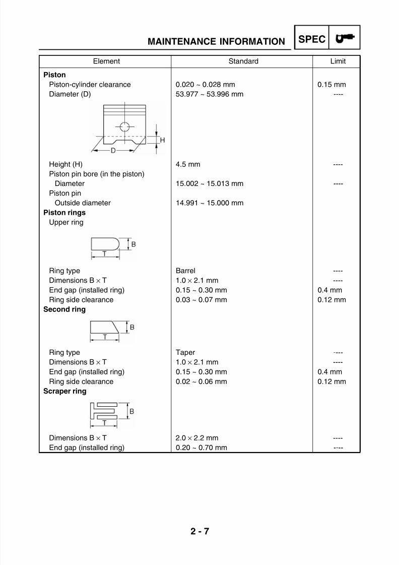
Element Standard Limit
Piston
Piston-cylinder clearance 0.020 ~ 0.028 mm 0.15 mm
Diameter (D) 53.977 ~ 53.996 mm ----
Height (H) 4.5 mm ----
Piston pin bore (in the piston)
Diameter 15.002 ~ 15.013 mm ----
Piston pin
Outside diameter 14.991 ~ 15.000 mm
Piston rings
Upper ring
Ring type Barrel ----
Dimensions B × T 1.0 × 2.1 mm ----
End gap (installed ring) 0.15 ~ 0.30 mm 0.4 mm
Ring side clearance 0.03 ~ 0.07 mm 0.12 mm
Second ring
Ring type Taper ----
Dimensions B × T 1.0 × 2.1 mm ----
End gap (installed ring) 0.15 ~ 0.30 mm 0.4 mm
Ring side clearance 0.02 ~ 0.06 mm 0.12 mm
Scraper ring
Dimensions B × T 2.0 × 2.2 mm ----
End gap (installed ring) 0.20 ~ 0.70 mm ----

7/22/2019 Yamaha xt 125 service manual
http://slidepdf.com/reader/full/yamaha-xt-125-service-manual 22/279
2 - 8
SPECMAINTENANCE INFORMATION
Crankshaft
Width (A) 46.95 ~ 47.00 mm ----
Maximum run out (C) ---- 0.03 mm
Side clearance (D) of the big end 0.15 ~ 0.45 mm 0.8 mm
BalancerBalancer drive method Sprocket ----
Clutch
Clutch type Wet-type, multiple-disc ----
Clutch release method Inner push, cam push ----
Push rod bending limit 0.5 mm
Control Left hand operation ----
Clutch cable clearance
(at the end of the clutch lever)
10.0 ~ 15.0 mm ----
Driving discs
Thickness 2.92 ~ 3.08 mm 2.80 mmDisc number 5 ----
Clutch discs
Thickness 1.05 ~ 1.35 mm 1.00 mm
Disc number 4 ----
Clutch spring
Free length 31 mm 29 mm
Spring number ----
Shifting mechanism
Shifting mechanism type Gearbox drum and guide bar ----
Air filter type Wet element ----
Element Standard Limit

7/22/2019 Yamaha xt 125 service manual
http://slidepdf.com/reader/full/yamaha-xt-125-service-manual 23/279
2 - 9
SPECMAINTENANCE INFORMATION
Element Standard Limit
Carburetor
Mark I.D. 3D6 ----
Main jet M.J. #105 ----
Main air jet M.A.J. 1.2 ----
Jet needle J.N. 5EJ9-2 ----
Needle jet N.J. N-7M (913) ----
Pilot outlet P.O. ø1.05 ----
Pilot jet P.J. #12.5 ----
Pilot air screw P.S. 1 ----
Bypass 1.6 ----
Valve seat size V.S. 1.8 ----
Starter jet G.S. 22.5 ----
Fuel level (with special tool) F.L. 7.5 mm ----
Power jet #60 ----
Float height 18.9 mm ----
Engine idling speed 1650 ~ 1850 rpm ----
Lubrication system
Oil pump type Trochoid type ----
End gap “A” 0.15 mm 0.2 mm
Side clearance 0.06 mm ~ 0.10 mm 0.15 mm
Housing and rotor clearance 0.06 mm ~ 0.10 mm 0.15 mm
7/22/2019 Yamaha xt 125 service manual
http://slidepdf.com/reader/full/yamaha-xt-125-service-manual 24/279
2 - 10
SPECMAINTENANCE INFORMATION
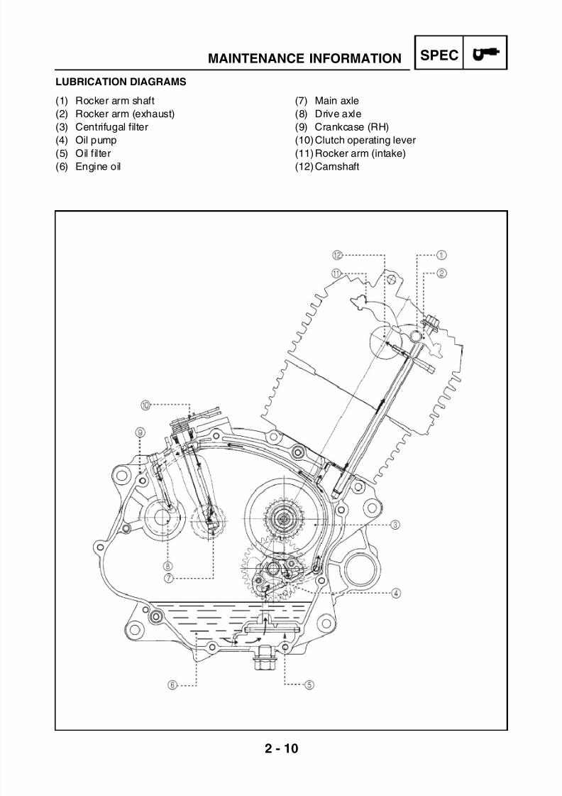
LUBRICATION DIAGRAMS
(1) Rocker arm shaft
(2) Rocker arm (exhaust)
(3) Centrifugal filter
(4) Oil pump(5) Oil filter
(6) Engine oil
(7) Main axle
(8) Drive axle
(9) Crankcase (RH)
(10)Clutch operating lever(11)Rocker arm (intake)
(12)Camshaft

7/22/2019 Yamaha xt 125 service manual
http://slidepdf.com/reader/full/yamaha-xt-125-service-manual 25/279
2 - 11
SPECMAINTENANCE INFORMATION
(1) Centrifugal filter
(2) Crankshaft
(3) Main axle
(4) Clutch
(5) Cover (RH
)
(6) Drive axle
(7) Cover (LH)
(8) Cylinder
(9) Head
(10)Camshaft
7/22/2019 Yamaha xt 125 service manual
http://slidepdf.com/reader/full/yamaha-xt-125-service-manual 26/279
2 - 12
SPECMAINTENANCE INFORMATION
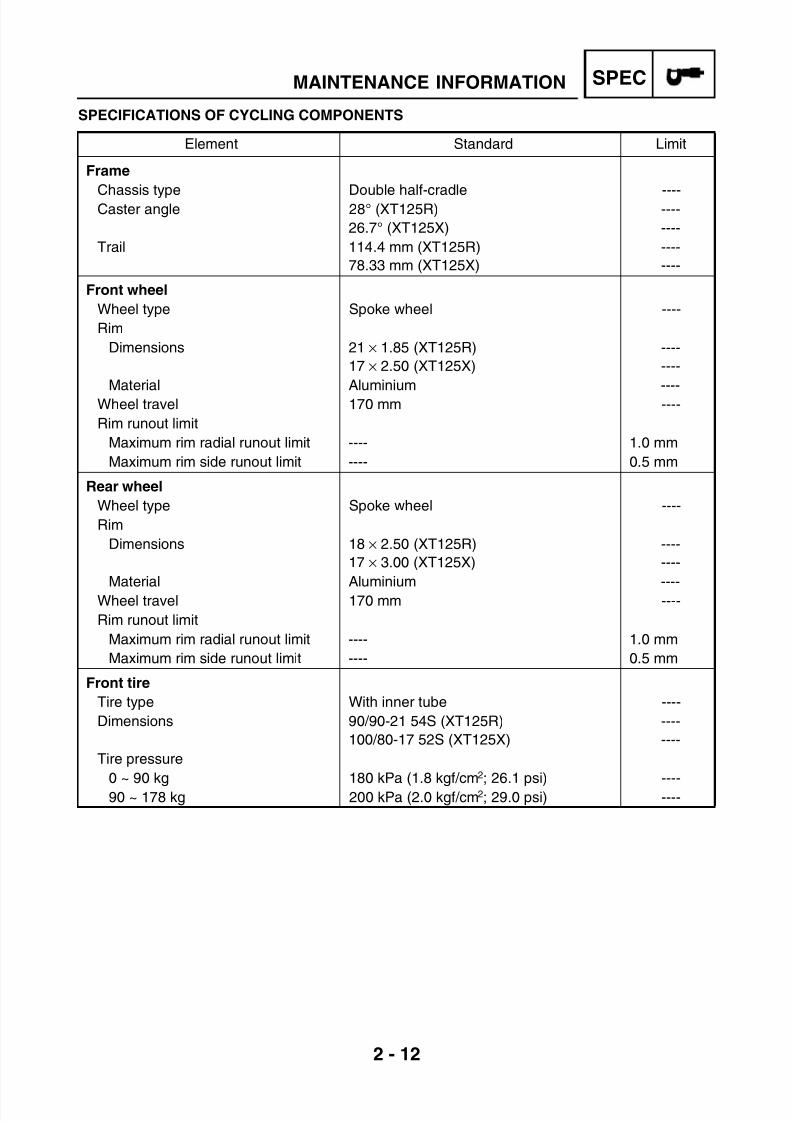
SPECIFICATIONS OF CYCLING COMPONENTS
Element Standard Limit
Frame
Chassis type Double half-cradle ----Caster angle 28° (XT125R)
26.7° (XT125X)
----
----
Trail 114.4 mm (XT125R)
78.33 mm (XT125X)
----
----
Front wheel
Wheel type Spoke wheel ----
Rim
Dimensions 21 × 1.85 (XT125R)
17 × 2.50 (XT125X)
----
----
Material Aluminium ----Wheel travel 170 mm ----
Rim runout limit
Maximum rim radial runout limit ---- 1.0 mm
Maximum rim side runout limit ---- 0.5 mm
Rear wheel
Wheel type Spoke wheel ----
Rim
Dimensions 18 × 2.50 (XT125R)
17 × 3.00 (XT125X)
----
----
Material Aluminium ----Wheel travel 170 mm ----
Rim runout limit
Maximum rim radial runout limit ---- 1.0 mm
Maximum rim side runout limit ---- 0.5 mm
Front tire
Tire type With inner tube ----
Dimensions 90/90-21 54S (XT125R)
100/80-17 52S (XT125X)
----
----
Tire pressure
0 ~ 90 kg 180 kPa (1.8 kgf/cm
2
; 26.1 psi) ----90 ~ 178 kg 200 kPa (2.0 kgf/cm2; 29.0 psi) ----

7/22/2019 Yamaha xt 125 service manual
http://slidepdf.com/reader/full/yamaha-xt-125-service-manual 27/279
2 - 13
SPECMAINTENANCE INFORMATION
Element Standard Limit
Rear tire
Tire type With inner tube ----
Dimensions 120/80-18 62S (XT125R)
130/70-17 62S (XT125X)
----
----
Tire pressure ----
0 ~ 90 kg 190 kPa (1.9 kgf/cm2; 27.6 psi) ----
90 ~ 178 kg 210 kPa (2.1 kgf/cm2; 30.5 psi)
Front brakes
Brake type Single disc brake ----
Control Right hand operation ----
Recommended liquid DOT 4 ----
Brake discs
Diameter × thickness 245 × 3.5 mm (XT125R)
260 × 3.5 mm (XT125X)
----
----
Pad inside thickness 3.0 mm 0.8 mm
Pad outside thickness 3.0 mm 0.8 mm
Pump inside diameter 11.0 mm ----
Caliper cylinder inside diameter 32.0 mm (XT125R)
25.0 mm (XT125X)
----
----
Lever free play 2 ~ 5 mm ----
Rear brakes
Brake type Single disc brake ----
Control Right foot operation ----
Recommended liquid DOT 4 ----
Brake discs
Diameter × thickness 218 × 3.5 mm ----
Brake pad lining thickness (inside) 4.0 mm 1.0 mm
Brake pad lining thickness (outside) 4.0 mm 1.0 mm
Pump inside diameter 12.7 mm ----
Caliper cylinder inside diameter 32.0 mm ----
Lever free play 15 mm ----
Steering
Steering bearing type Taper roller ----
Lock-to-lock angle (LH) 45.0° ----
Lock-to-lock angle (RH) 45.0° ----

7/22/2019 Yamaha xt 125 service manual
http://slidepdf.com/reader/full/yamaha-xt-125-service-manual 28/279
2 - 14
SPECMAINTENANCE INFORMATION
Element Standard Limit
Front suspension
Suspension type Telescopic fork ----
Front fork type Coil spring/oil damper ----
Front fork travel 250.0 mm ----
Spring
Free length 575 mm ----
Spring rate (K1) 4.8 N/mm ----
Fork oil
Recommended oil 10 W fork oil or equivalent ----
Amount (on each fork) 285 cc ----
Level (from the inner tube top, with
completely compressed tube and
without fork spring)
180 mm ----
Inner tube outside diameter ø36 ----
Rear suspension
Suspension type Swingarm (monocross) ----
Rear sock absorber unit travel 45.0 mm ----
Spring
Free length 163.0 mm ----
Installed length 158.0 mm ----
Spring rate (K1) 177 N/mm (17.7 kg/mm; 1010.67 lb/in) ----
Spring travel 55.0 mm ----
Available optional spring No ----
Transmission chain
Type/manufacturer 428H G&G/DID ----
Number of links 128 (XT125R)
126 (XT125X)
----
Drive chain slack 25.0 ~ 40.0 mm ----

7/22/2019 Yamaha xt 125 service manual
http://slidepdf.com/reader/full/yamaha-xt-125-service-manual 29/279
2 - 15
SPECMAINTENANCE INFORMATION
ELECTRICAL SYSTEM SPECIFICATIONS
Element Standard Limit
Electrical system voltage 12 V ----
Ignition system
System type CDI ----
Ignition timing 0.0° BTDC at 1400 rpm ----
Advancer type Electrical ----
Pickup coil resistance 240±20% at 20°C (68°F) ----
Cable colour (Blue/yellow–green)
Model of ignition system with transistor
coil/manufacturer
3D6-MORIYAMA ----
Ignition coil
Model/manufacturer 5HH ----
Spark minimum length 7.0 mm ----
Primary coil resistance 0.27 ~ 0.33 Ω at 20°C (68°F) ----
Secondary coil resistance 2.84 ~ 3.48 kΩ at 20°C (68°F) ----
Spark plug cap
Material Rubber ----
Resistor 4.0 ~ 6.0 kΩ at 20°C (68°F) ----
Charging system
System type Magneto AC ----
Model/manufacturer 3D6 MORIYAMA ----
Rated power 14.0 V/20.8 A at 5000 rpm ----
Stator coil resistance 0.51 ~ 0.77 Ω at 20°C (68°F) ----
Rectifier/ regulator
Regulator type Semi conductor - short circuit type ----
No load regulated voltage 13.0 ~ 14.0 V ----
Rectifier capacity 8.0 A ----
Withstand voltage 400.0 V ----
Battery
Battery type/manufacturer GT6B-3/GS ----
Battery voltage/capacity 12 V/6.5 AH ----
Headlight type Halogen bulb ----
Light (voltage/wattage × quantity)
Neutral indicator light LED × 1 ----
High beam indicator light LED × 1 ----
Fuel level indicator light LED × 1 ----
Flasher light LED × 1 ----
Parking lights LED × 1 ----

7/22/2019 Yamaha xt 125 service manual
http://slidepdf.com/reader/full/yamaha-xt-125-service-manual 30/279
2 - 16
SPECMAINTENANCE INFORMATION
Element Standard Limit
Bulbs (voltage/wattage × quantity)
Headlight 12 V 35/35 W × 1 ----
Service light 12 V 5 W × 1 ----
Rear position/stop light 12 V 5/21 W × 1 ----
Front flasher light 12 V 10 W × 2 ----
Rear flasher light 12 V 10 W × 2 ----
Meter lighting LED ----
Electric ignition system
Starter
Model/manufacturer 3MB/Moric ----
Delivered power 0.2 kW ----
Induced winding resistance 0.0315 ~ 0.0385 Ω at 20°C (68°F) ----
Brushes
Overall length 12.5 mm 3.5 mm
Spring force 3.92 ~ 5.88 N ----
Commutator diameter 17.6 mm 16.6 mm
Mica undercut 1.35 mm ----
Starter relay
Model/manufacturer NAIS ----
Amperage 70 A ----
Coil resistance 90 ~ 100 Ω ----
Horn
Warning horn type Plate ----Model/manufacturer × amount K70H/LEB × 1 ----
Maximum amperage 3.0 A ----
Performance 105 ~ 118 db (A) ----
Turn signal/emergency flasher relay
Relay type Full transistor type ----
Model/manufacturer Cablologica/CBL ----
Integrated automatic stopping device No ----
Flashing frequency 80 ~ 160 cycles/minute ----
Output 10 W × 2 +2.0 W ----
Fuses (amperage × amount)Main fuse 10 A × 1 ----

7/22/2019 Yamaha xt 125 service manual
http://slidepdf.com/reader/full/yamaha-xt-125-service-manual 31/279
2 - 17
SPECMAINTENANCE INFORMATION
CONVERSION TABLE
All specifications in this Manual keep to the
International System (IS) and to the METRIC
SYSTEM UNITS.
Use the following table to convert valuesexpressed in the METRIC SYSTEM UNITS
into values expressed in IMPERIAL UNITS.
CONVERSION TABLE
MAIN SPECIFICATIONS OF THE
TIGHTENING TORQUES
The table shows the tightening torques of stan-
dard nuts and bolts with standard ISO thread
pitch. The tightening torques of componentsand special units are to be found in the special
chapters of this Manual. In order to avoid
deformation, tighten the nut or bolt units in
gradual or crisscross way, until you reach the
specified tightening torque. If not otherwise
specified, the recommended tightening
torques are for clean and dry threads. The
components must be at ambient temperature.
A: Wrench opening
B: Thread outside diameter
Example
METRIC
SYSTEMOVERDRIVE IMPERIAL
** mm × 0.03937 = ** in
2 mm × 0.03937 = 0.08 in
FROM METRIC SYSTEM TO IMPERIAL SYSTEM
Tightening
torque
Metric sys-
tem unitsOverdrive Imperial unit
m · kg
m · kg
cm · kg
cm · kg
7.233
86.794
0.0723
0.8679
ft · lb
in · lb
ft · lb
in · lb
Counter-
weight
kg
g
2.205
0.03527
lb
oz
Speed km/h 0.6214 mph
Distance
km
m
m
cm
mm
0.6214
3.281
1.094
0.3937
0.03937
mi
ft
yd
in
in
Volume/
Capacity
cc (cm3)
cc (cm3)
l (litres)
l (litres)
0.03527
0.06102
0.8799
0.2199
oz (IMP liq.)
cu · in
qt (IMP liq.)
gal (IMP liq.)
Otherkg/mmkg/cm2
Celsius
degrees (°C)
55.99714.2234
9/5+32
lb/inpsi (lb/in2)
Fahrenheit
degrees (°F)
A
(nut)
B
(bolt)
General tightening
torques
Nm m · kg ft · lb
10 mm 6 mm 6 0.6 4.3
12 mm 8 mm 15 1.5 11
14 mm 10 mm 30 3.0 22
17 mm 12 mm 55 5.5 40
19 mm 14 mm 85 8.5 61
22 mm 16 mm 130 13.0 94
7/22/2019 Yamaha xt 125 service manual
http://slidepdf.com/reader/full/yamaha-xt-125-service-manual 32/279
2 - 18
SPECTIGHTENING TORQUES
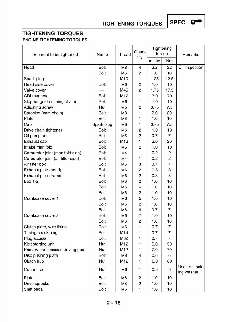
TIGHTENING TORQUESENGINE TIGHTENING TORQUES
Element to be tightened Name Thread
Quan-
tity
Tightening
torqueRemarks
m · kg Nm
Head Bolt M8 4 2.2 22 Oil inspection
Bolt M6 2 1.0 10
Spark plug — M10 1 1.25 12.5
Head side cover Bolt M6 2 1.0 10
Valve cover — M45 2 1.75 17.5
CDI magneto Bolt M12 1 7.0 70
Stopper guide (timing chain) Bolt M6 1 1.0 10
Adjusting screw Nut M5 2 0.75 7.5
Sprocket (cam chain) Bolt M8 1 2.0 20Plate Bolt M6 1 1.0 10
Cap Spark plug M8 1 0.75 7.5
Drive chain tightener Bolt M6 2 1.0 10
Oil pump unit Bolt M6 2 0.7 7
Exhaust cap Bolt M12 1 2.0 20
Intake manifold Bolt M6 2 1.0 10
Carburetor joint (manifold side) Bolt M4 1 0.2 2
Carburetor joint (air filter side) Bolt M4 1 0.2 2
Air filter box Bolt M6 3 0.7 7
Exhaust pipe (head) Bolt M6 2 0.8 8Exhaust pipe (frame) Bolt M6 2 0.8 8
Box 1-2 Bolt M6 2 1.0 10
Bolt M6 6 1.0 10
Bolt M6 2 1.0 10
Crankcase cover 1 Bolt M6 5 1.0 10
Bolt M6 2 1.0 10
Bolt M6 6 0.7 7
Crankcase cover 2 Bolt M6 7 1.0 10
Bolt M6 2 1.0 10
Clutch plate, wire fixing Bolt M6 1 0.7 7
Timing check plug Bolt M14 1 0.7 7
Plug access Bolt M32 1 0.7 7
Kick starting unit Nut M12 1 5.0 50
Primary transmission driving gear Nut M12 1 7.0 70
Disc pushing plate Bolt M8 4 0.6 6
Clutch hub Nut M12 1 6.0 60
Control rod Nut M6 1 0.8 8Use a lock-
ing washer
Plate Bolt M6 2 1.0 10
Drive sprocket Bolt M8 2 1.0 10
Shift pedal Bolt M6 1 1.0 10

7/22/2019 Yamaha xt 125 service manual
http://slidepdf.com/reader/full/yamaha-xt-125-service-manual 33/279
2 - 19
SPECTIGHTENING TORQUES
Cam Bolt M6 1 1.2 12
Stopping lever Bolt M6 1 1.0 10
Coil (Pick-up) Bolt M6 2 1.0 10
Neutral position switch — M10 1 0.13 1.3
Stator Bolt M6 3 1.0 10
Element to be tightened Name ThreadQuan-
tity
Tightening
torque Remarks
m · kg Nm
Tightening sequence
Head
Crankcase
Right Left

7/22/2019 Yamaha xt 125 service manual
http://slidepdf.com/reader/full/yamaha-xt-125-service-manual 34/279
2 - 20
SPECTIGHTENING TORQUES
TIGHTENING TORQUES OF CYCLING COMPONENTS
Element to be tightened ThreadTightening torque
Remarksm · kg Nm
Front wheel axle M14 4.5 45Front wheel axle tightening bolt M8 2.0 20
Front brake caliper M8 3.0 30
(Front) Engine mount M8 2.3 23
(Rear) Engine and frame mount M8 2.3 23
Swingarm pivot nut M14 6.0 60
(Front brake) master cylinder clamp M6 0.6 6
Rear wheel axle nut M14 8.5 85
Throttle twist grip M6 0.3 3
Rear Shock Absorber M10 4.5 45
Upper bracket M8 2.0 20Handle bar clamps M8 2.15 21.5
Steering nut M25 3.0 30
Rear frame M8 2.0 20

7/22/2019 Yamaha xt 125 service manual
http://slidepdf.com/reader/full/yamaha-xt-125-service-manual 35/279
2 - 21
SPECLUBRICATION POINTS AND LUBRICANT TYPES
LUBRICATION POINTS AND LUBRICANT TYPESENGINE
Lubrication points Symbol
Oil seal lips LS
O-rings LS
Bearings E
Head tightening bolts E
Cylinder tightening bolts E
Crank pin E
Internal surface of the twist grip M
Big end thrust surface E
Piston pin E
Piston ring and groove E
Balancer counter-weight tightening nut E
Internal surface of magneto rotor tightening nut AC E
Valve stem/Valve guide (intake and exhaust) M
Valve stem ends (intake and exhaust) M
Rocker arm shaft E
Cam shaft lobes M
(Outside and inside) Oil pump rotors E
Oil pump shaft E
Kick starter axle surface E
Drive gear surface E
Kick starter axle gear E
Kick starter idle gear E
Tightening nut of the primary transmission driving gear M
Primary transmission driven gear E
Clutch hub tightening nut E
Control rod M
Drive gear (wheel/front sprocket)M
Main and driving axle M
Gearbox forks E
Gearbox boss E
Gearbox shaft E
Gearbox shaft spacer E

7/22/2019 Yamaha xt 125 service manual
http://slidepdf.com/reader/full/yamaha-xt-125-service-manual 36/279
2 - 22
SPECLUBRICATION POINTS AND LUBRICANT TYPES
CYCLING COMPONENTS
Lubrication points Symbol
Crankcase mating surface Yamaha glue no. 1215
Flywheel cover AC Yamaha glue no. 1215
Oil retainer support tightening bolt Yamaha glue no. 1215
Lubrication points Symbol
Rear wheel hub LS
Swingarm pivot and seals LS
Surface of dust seal cover thrust bearing LS
Pivot of brake pedal LS
(Upper and lower) Steering sleeve tube bearings LS
Tracks of (upper and lower) steering sleeve tube bearings LS
Inside surface of tube guide (twist grip) LS
Clutch lever pivot bolt LS
Side stand pivot LS
Footrest pivot point LS
Footrest spring end LS
Outside surface of rear axle shaft LS
Pivot point of passenger’s footrest LS
Fuel cock connector (1)B
C/km sensor transmission connector (1)B
Dashboard connector (2)B
Connector CDI magneto (2)B
(1)
Up to the frame number 74007950 included (blue enduro)
Up to the frame number 74009373 included (blue motard)
Up to the frame number 74007950 included (black enduro)
Up to the frame number 74009706 included (red motard)
Up to the frame number 74010046 included (English version)
(2)
From the frame number following 74007950 (blue enduro)
From the frame number following 74009373 (blue motard)
From the frame number following 74007950 (black enduro)
From the frame number following 74009706 (red motard)
From the frame number following 74010046 (English version)

7/22/2019 Yamaha xt 125 service manual
http://slidepdf.com/reader/full/yamaha-xt-125-service-manual 37/279
2 - 23
SPECCABLE ROUTING
CABLE ROUTING(1) Clutch cable(2) Starter cable(3) (Left) Front flasher lead(4) (Right) Front flasher lead
(5) Front headlight lead(6) Starting enabling cable(7) Front brake light switch lead(8) Front brake hose(9) Front brake(10) Throttle cable(11) Starter relay lead(12) Horn lead(13) Main switch connector(14) Starting switch terminal board connector
(15) Breather hose valve of air induction system(16) Valve intake hose of air induction system(17) Vacuum hose of air induction system(18) Air breather hose
(19) Flywheel connector(20) Neutral switch lead(21) Fuel cock vacuum hose(22) Fuel hose(23) Air induction system valve(24) Regulator(25) Starter relay

7/22/2019 Yamaha xt 125 service manual
http://slidepdf.com/reader/full/yamaha-xt-125-service-manual 38/279
2 - 24
SPECCABLE ROUTING
(26) Flasher relay(27) Thermal sensor(28) Regulator ground cable(29) Carburetor heater(30) Main switch
1. Insert device (A) after connecting connector
(13) and close rubber clamp (B).
2. Pass the cables through frame (C) and lock
it with clamps (D).
3. To remove connector (14), cut clamps (E)
and remove rubber cover (F).
4. Insert clutch cable (1) into cable guide (G).
5. Insert cable (20) into the housing on the
engine crankcase; lock the cable on neutral
position switch with screw (N).
6. Connect hose (16) to hose (17) with clamp
(H).7. Tighten breather hose (18) with clamp (L)
and cable guides (M).

7/22/2019 Yamaha xt 125 service manual
http://slidepdf.com/reader/full/yamaha-xt-125-service-manual 39/279
2 - 25
SPECCABLE ROUTING
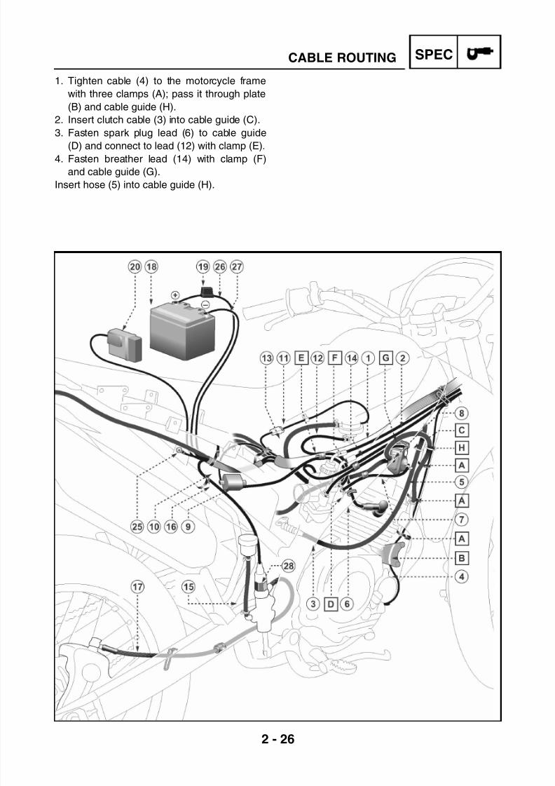
(1) Throttle cable(2) Starter cable(3) Clutch cable(4) Lead (+) of the starter(5) Breather hose valve of air induction system(6) Spark plug lead(7) Vacuum hose of air induction system(8) Air induction system valve(9) Ignition coil(10) Coil lead(11) Fuel level lead(12) Fuel cock vacuum hose(13) Fuel hose(14) Air breather hose(15) Rear brake reservoir(16) Rear brake light switch lead
(17) Rear brake hose(18) Battery(19) Main fuse 10A(20) CDI unit(21) (Right) Rear flasher lead(22) (Left) Rear flasher lead(23) Rear position/stop light(24) Plate light lead(25) Ground cable(26) Cable battery (+)(27) Cable battery (-)(28) Rear brake light switch
7/22/2019 Yamaha xt 125 service manual
http://slidepdf.com/reader/full/yamaha-xt-125-service-manual 40/279
2 - 26
SPECCABLE ROUTING
1. Tighten cable (4) to the motorcycle frame
with three clamps (A); pass it through plate
(B) and cable guide (H).
2. Insert clutch cable (3) into cable guide (C).
3. Fasten spark plug lead (6) to cable guide(D) and connect to lead (12) with clamp (E).
4. Fasten breather lead (14) with clamp (F)
and cable guide (G).
Insert hose (5) into cable guide (H).

7/22/2019 Yamaha xt 125 service manual
http://slidepdf.com/reader/full/yamaha-xt-125-service-manual 41/279
INSPADJ
CHAPTER 3
PERIODIC INSPECTIONS AND ADJUSTMENTS
INTRODUCTION..............................................................................................3-1MAINTENANCE INTERVAL TABLE ......................................................... 3-1
SEAT, TANK PANEL AND FUEL TANK ........................................................3-2SEAT REMOVAL.......................................................................................3-2SEAT INSTALLATION...............................................................................3-2TANK PANEL REMOVAL..........................................................................3-2TANK PANEL INSTALLATION..................................................................3-2FUEL TANK REMOVAL ............................................................................ 3-3FUEL TANK INSTALLATION .................................................................... 3-3
FRONT MUDGUARD AND HEADLIGHT HOLDER .......................................3-4FRONT MUDGUARD REMOVAL ............................................................. 3-4FRONT MUDGUARD INSTALLATION .....................................................3-4HEADLIGHT HOLDER REMOVAL ...........................................................3-4HEADLIGHT HOLDER INSTALLATION ...................................................3-5
SUMP COVER, SIDE PANELS, TAIL COWLING ANDREAR MUDGUARD........................................................................................3-6
ENGINE SUMP COVER REMOVAL......................................................... 3-6ENGINE SUMP GUARD INSTALLATION.................................................3-6SIDE COVER REMOVAL..........................................................................3-6SIDE COVER INSTALLATION.................................................................3-6
TAIL COWLING REMOVAL ...................................................................... 3-7TAIL COWLING INSTALLATION .............................................................. 3-7REAR MUDGUARD REMOVAL................................................................3-7REAR MUDGUARD INSTALLATION........................................................3-8
ENGINE ...........................................................................................................3-9VALVE CLEARANCE ADJUSTMENT.......................................................3-9CO MEASUREMENT AND IDLING SPEED ADJUSTMENT .................. 3-11THROTTLE CABLE ADJUSTMENT........................................................3-13SPARK PLUG INSPECTION...................................................................3-13IGNITION TIMING CHECK ..................................................................... 3-15COMPRESSION PRESSURE MEASUREMENT....................................3-16ENGINE OIL LEVEL INSPECTION.........................................................3-17
ENGINE OIL CHANGE............................................................................3-18OIL PRESSURE INSPECTION ............................................................... 3-19CLEANING THE AIR FILTER..................................................................3-19MANIFOLD AND INLET SLEEVE INSPECTION .................................... 3-20FUEL LINE INSPECTION ....................................................................... 3-21CRANKCASE VENTILATION HOSE INSPECTION ............................... 3-21EXHAUST SYSTEM INSPECTION.........................................................3-21
FRAME ..........................................................................................................3-22CLUTCH ADJUSTMENT.........................................................................3-22FRONT BRAKE FLUID LEVEL INSPECTION ........................................3-22FRONT BRAKE PAD INSPECTION........................................................3-23
AIR BLEEDING (FRONT BRAKE SYSTEM)...........................................3-24REAR BRAKE PEDAL ADJUSTMENT ...................................................3-25DRIVE CHAIN SLACK ADJUSTMENT ...................................................3-26DRIVE CHAIN LUBRICATION ................................................................ 3-27STEERING HEAD INSPECTION ............................................................3-28FRONT SUSPENSION INSPECTION.....................................................3-29REAR SHOCK-ABSORBER POSITION ADJUSTMENT ........................ 3-30

7/22/2019 Yamaha xt 125 service manual
http://slidepdf.com/reader/full/yamaha-xt-125-service-manual 42/279
INSPADJ
TYRE INSPECTION ................................................................................ 3-31SPOKE INSPECTION AND TIGHTENING .............................................3-33WHEEL INSPECTION.............................................................................3-33CABLE INSPECTION AND LUBRICATION ............................................3-34LEVER AND PEDAL LUBRICATION ...................................................... 3-34
ELECTRIC SYSTEM .....................................................................................3-35BATTERY INSPECTION ......................................................................... 3-35FUSE INSPECTION 10A.........................................................................3-36HEADLIGHT BEAM ADJUSTMENT........................................................3-38CHANGING FRONT HEADLIGHT BULBS .............................................3-38REAR TAIL /BRAKE LIGHT BULB REPLACEMENT..............................3-39
7/22/2019 Yamaha xt 125 service manual
http://slidepdf.com/reader/full/yamaha-xt-125-service-manual 43/279
3 - 1
INSPADJ
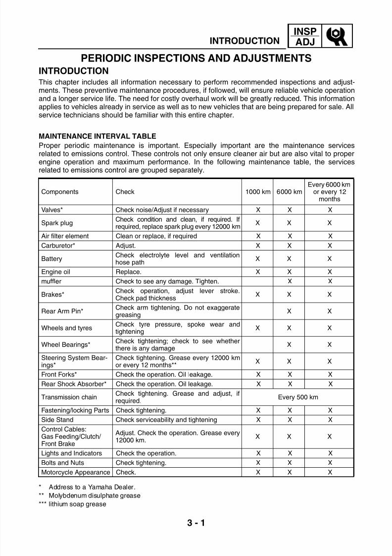
PERIODIC INSPECTIONS AND ADJUSTMENTSINTRODUCTIONThis chapter includes all information necessary to perform recommended inspections and adjust-ments. These preventive maintenance procedures, if followed, will ensure reliable vehicle operation
and a longer service life. The need for costly overhaul work will be greatly reduced. This informationapplies to vehicles already in service as well as to new vehicles that are being prepared for sale. Allservice technicians should be familiar with this entire chapter.
MAINTENANCE INTERVAL TABLE
Proper periodic maintenance is important. Especially important are the maintenance servicesrelated to emissions control. These controls not only ensure cleaner air but are also vital to properengine operation and maximum performance. In the following maintenance table, the servicesrelated to emissions control are grouped separately.
* Address to a Yamaha Dealer.** Molybdenum disulphate grease
*** lithium soap grease
Components Check 1000 km 6000 km
Every 6000 km
or every 12months
Valves* Check noise/Adjust if necessary X X X
Spark plugCheck condition and clean, if required. Ifrequired, replace spark plug every 12000 km
X X X
Air filter element Clean or replace, if required X X X
Carburetor* Adjust. X X X
BatteryCheck electrolyte level and ventilationhose path
X X X
Engine oil Replace. X X X
muffler Check to see any damage. Tighten. X X
Brakes* Check operation, adjust lever stroke.Check pad thickness
X X X
Rear Arm Pin*Check arm tightening. Do not exaggerategreasing
X X
Wheels and tyresCheck tyre pressure, spoke wear andtightening
X X X
Wheel Bearings*Check tightening; check to see whetherthere is any damage
X X
Steering System Bear-ings*
Check tightening. Grease every 12000 kmor every 12 months**
X X X
Front Forks* Check the operation. Oil leakage. X X X
Rear Shock Absorber* Check the operation. Oil leakage. X X X
Transmission chainCheck tightening. Grease and adjust, ifrequired.
Every 500 km
Fastening/locking Parts Check tightening. X X X
Side Stand Check serviceability and tightening X X X
Control Cables:Gas Feeding/Clutch/ Front Brake
Adjust. Check the operation. Grease every12000 km.
X X X
Lights and Indicators Check the operation. X X X
Bolts and Nuts Check tightening. X X X
Motorcycle Appearance Check. X X X
INTRODUCTION

7/22/2019 Yamaha xt 125 service manual
http://slidepdf.com/reader/full/yamaha-xt-125-service-manual 44/279
3 - 2
INSPADJSEAT, TANK PANEL AND FUEL TANK
SEAT, TANK PANEL AND FUEL
TANKSEAT REMOVAL
WARNINGSecurely support the motorcycle so there
is no danger of it falling over.
1. Stand the motorcycle on a level surface.
2. Remove
• Bolt (1)
• Seat (2)
SEAT INSTALLATION
1. Install• Seat (2)
• Bolt (1)
TANK PANEL REMOVAL
WARNING
Securely support the motorcycle so there
is no danger of it falling over.
1. Stand the motorcycle on a level surface.
2. Remove
• Seat
See “SEAT REMOVAL” page 3-2
• Left cover (1)
• Right cover (2)
• Radiator grid (3)
TANK PANEL INSTALLATION1. Install
• Radiator grid (3)
• Left cover (1)
• Right cover (2)
• Seat
See “SEAT INSTALLATION” page 3-2
T R .
.
Bolt (1) :0.7 Kgf·m (7 N·m)
T R .
.
Cover bolts:0.25 Kgf·m (2.5 N·m) ± 25%

7/22/2019 Yamaha xt 125 service manual
http://slidepdf.com/reader/full/yamaha-xt-125-service-manual 45/279
3 - 3
INSPADJSEAT, TANK PANEL AND FUEL TANK
FUEL TANK REMOVAL
WARNING
Securely support the motorcycle so there
is no danger of it falling over.
1. Stand the motorcycle on a level surface.
2. Remove
• Seat
See “SEAT REMOVAL” page 3-2
• Side covers
See “TANK PANEL REMOVAL” page 3-2
3. Unscrew
• Tank bolts (1)
• Fuel tank cap (6)
4. Disconnect• Fuel tap connector (2)
• Fuel supply hose (3)
• Fuel tap vacuum hose (4)
WARNING
The fuel is highly flammable. Avoid fuel
discharge on the hot motor.
5. Remove
• Gasket (7)
• Tank cover (8)• Fuel tank (5)
FUEL TANK INSTALLATION
1. Install
• Fuel tank (5)
• Tank cover (8)
• Gasket (7)
2. Connect
• Fuel tap connector (2)
• Fuel supply hose (3)
• Fuel tap vacuum hose (4)3. Screw
• Tank bolts (1)
• Fuel tank cap (6)
4. Install
• Tank panel
See “TANK PANEL INSTALLATION” page
3-2• Seat
See “SEAT INSTALLATION” page 3-2
T R .
.
Tank bolts:0.7 Kgf·m (7 N·m)

7/22/2019 Yamaha xt 125 service manual
http://slidepdf.com/reader/full/yamaha-xt-125-service-manual 46/279
3 - 4
INSPADJFRONT MUDGUARD AND HEADLIGHT HOLDER
FRONT MUDGUARD AND
HEADLIGHT HOLDERFRONT MUDGUARD REMOVAL
WARNINGSecurely support the motorcycle so there
is no danger of it falling over.
1. Stand the motorcycle on a level surface.
2. Remove
• Bolts (1)
• Front mudguard (2)
FRONT MUDGUARD INSTALLATION
1. Install
• Front mudguard (2)
• Bolts (1)
HEADLIGHT HOLDER REMOVAL
WARNING
Securely support the motorcycle so there
is no danger of it falling over.
1. Stand the motorcycle on a level surface.
2. Remove
• Front mudguard
See “FRONT MUDGUARD REMOVAL”
page 3-43. Disassemble
• Right turn signal lens (1)
• Left turn signal lens (2)
4. Disconnect
• Right turn signal wires
• Left turn signal wires
NOTE:
Extract the wires in order to remove the head-
light holder

7/22/2019 Yamaha xt 125 service manual
http://slidepdf.com/reader/full/yamaha-xt-125-service-manual 47/279
3 - 5
INSPADJFRONT MUDGUARD AND HEADLIGHT HOLDER
5. Remove
• Right turn signal (3)
• Left turn signal (4)
• Head lamp (5)
NOTE:Remove the head lamp from the seating posi-
tion
• Headlight holder (6)
HEADLIGHT HOLDER INSTALLATION
1. Install
• Headlight holder (6)
• Front lamp (5)2. Connect
• Right turn signal wires
• Left turn signal wires
3. Assemble
• Right turn signal lens (1)
• Left turn signal lens (2)
• Right turn signal (3)
• Left turn signal (4)
• Front mudguard
See “FRONT MUDGUARD INSTALLA-
TION” page 3-4

7/22/2019 Yamaha xt 125 service manual
http://slidepdf.com/reader/full/yamaha-xt-125-service-manual 48/279
3 - 6
INSPADJ
SUMP COVER, SIDE PANELS, TAIL COWLING AND
REAR MUDGUARD
SUMP COVER, SIDE PANELS, TAIL
COWLING AND REAR MUDGUARDENGINE SUMP COVER REMOVAL
WARNINGSecurely support the motorcycle so there
is no danger of it falling over.
1. Stand the motorcycle on a level surface.
2. Remove
• Bolts (1)
• Sump guard (2)
ENGINE SUMP GUARD INSTALLATION1. Install
• Sump guard (2)
• Bolts (1)
SIDE COVER REMOVAL
WARNING
Securely support the motorcycle so there
is no danger of it falling over.
1. Stand the motorcycle on a level surface.
2. Remove
• Bolts (1)
• Bushings (2)
• Right side cover (3)
• Left side cover (4)
SIDE COVER INSTALLATION
1. Install• Right side cover (3)
• Left side cover (4)
• Bushings (2)
• Bolts (1)

7/22/2019 Yamaha xt 125 service manual
http://slidepdf.com/reader/full/yamaha-xt-125-service-manual 49/279
3 - 7
INSPADJ
SUMP COVER, SIDE PANELS, TAIL COWLING AND
REAR MUDGUARD
TAIL COWLING REMOVAL
WARNING
Securely support the motorcycle so there
is no danger of it falling over.
1. Stand the motorcycle on a level surface.
2. Remove
• Bolts (1)
• Bushings (2)
• Tail cowling (3)
TAIL COWLING INSTALLATION
1. Install
• Tail cowling (3)• Bushings (2)
• Bolts (1)
REAR MUDGUARD REMOVAL
WARNING
Securely support the motorcycle so there
is no danger of it falling over.
1. Stand the motorcycle on a level surface.
2. Remove
• Seat
See “SEAT REMOVAL” page 3-2
• Tail cowling
See “TAIL COWLING REMOVAL” page 3-7
3. Disassemble
• Right turn signal lens (1)
• Left turn signal lens (2)
• Wire retaining plate (3)4. Disconnect
• Right turn signal wires
• Left turn signal wires
• Rear light wires
• Plate light wires
• Battery leads
• “CDI” control unit wires

7/22/2019 Yamaha xt 125 service manual
http://slidepdf.com/reader/full/yamaha-xt-125-service-manual 50/279
3 - 8
INSPADJ
SUMP COVER, SIDE PANELS, TAIL COWLING AND
REAR MUDGUARD
NOTE:
Extract the wires in order to remove the rear
mudguard
5. Remove• Right turn signal (4)
• Left turn signal (5)
• Battery (6)
• “CDI” control unit (7)
• Bolts (8)
• Bushings (9)
• Rear mudguard (10)
REAR MUDGUARD INSTALLATION
1. Install
• Rear mudguard (10)
• Bushings (9)
• Bolts (8)
• Battery (6)
• “CDI” control unit (7)
2. Connect
• Right turn signal wires
• Left turn signal wires
• Rear light wires
• Plate light wires• Battery leads
• “CDI” control unit wires
3. Assemble
• Wire retaining plate (3)
• Right turn signal (4)
• Left turn signal (5)
• Right turn signal lens (1)
• Left turn signal lens (2)
• Tail cowling
See “TAIL COWLING INSTALLATION”
page 3-7• Seat
See “SEAT INSTALLATION” page 3-2

7/22/2019 Yamaha xt 125 service manual
http://slidepdf.com/reader/full/yamaha-xt-125-service-manual 51/279
3 - 9
INSPADJENGINE
ENGINEVALVE CLEARANCE ADJUSTMENT
NOTE:
Valve clearance adjustment must be made
when the engine is cool, at room temperature.
When the valve clearance is to be measured
or adjusted, the piston must be at Top Dead
Center (T.D.C.) on the compression stroke.
WARNING
Securely support the motorcycle so there
is no danger of it falling over.
1. Remove
• Spark plug
• Bolts (1)
• Cylinder head side cover (2)
• Valve cover (intake side) (3)
• Valve cover (exhaust side) (4)
2. Remove
• Timing check plug with O-Ring (1)
• Center plug with O-Ring (2)
*****************************************************
Measurement steps
• Rotate the crankshaft counterclockwise to
align the mark (A) on the rotor with the sta-
tionary pointer (B) on the crankcase cover.
The piston must be at Top Dead Center
(TDC) and the marking on the cam sprocket
must be aligned with the cylinder head
marking.
*****************************************************

7/22/2019 Yamaha xt 125 service manual
http://slidepdf.com/reader/full/yamaha-xt-125-service-manual 52/279
3 - 10
INSPADJENGINE
3. Measure• Valve clearance
Measure the valve clearance by using a
feeler gauge
Out of specification → Adjust
4. Adjust
• Valve clearance
*****************************************************
Adjustment steps
• Loosen the locknut (1)• Turn the adjuster (2) clockwise or counter-
clockwise with the valve adjusting tool (3)until specified clearance is obtained.
• Hold the adjuster to prevent it from movingand tighten the locknut.
• Measure the valve clearance
• If the clearance is incorrect, repeat above
steps until specified clearance is obtained
*****************************************************
5. Install• Timing check plug with O-Ring (1)
• Center plug with O-Ring (2)
Valve clearance (cold):Intake valve: 0.08 ~ 0.12 mmExhaust valve: 0.10 ~ 0.14 mm
Turning clockwise → Clearance isdecreased
Turning counterclockwise → Clearanceis increased
Valve adjusting tool:90890-01311-09
T R .
.
Locknut:0.8 Kgf·m (8 N·m)

7/22/2019 Yamaha xt 125 service manual
http://slidepdf.com/reader/full/yamaha-xt-125-service-manual 53/279
3 - 11
INSPADJENGINE
6. Install
• Valve cover with O-Ring (1)
• Spark plug
• Cylinder head side cover (2)
T R .
.
Valve cover (intake and exhaust):1.75 Kgf·m (17.5 N·m)
Bolts cylinder head side cover:1.0 Kgf·m (10 N·m)
Spark plug:1.25 Kgf·m (12.5 N·m)
CO MEASUREMENT AND IDLING SPEED
ADJUSTMENT
1. Start the engine and let it warm up for
several minutes
2. Connect
• Inductive tachometer to the spark plug lead
Engine tachometer:90890-06760
3. Check
• Engine idling speed
Out of specification → Adjust
Turn the throttle stop screw (1) clockwise or
counterclockwise until specified idling
speed is obtained.
Engine idling speed:1300 ~ 1500 rpm

7/22/2019 Yamaha xt 125 service manual
http://slidepdf.com/reader/full/yamaha-xt-125-service-manual 54/279
3 - 12
INSPADJENGINE
4. Install
• Sampling probe CO tester (1) to the
exhaust pipe (2)
Out of specification → Adjust
CO concentration:Maximum value 4.5%
5. Adjust
• CO concentration
*****************************************************
Adjustment steps
• Turn the pilot screw (2) in or out to achieve
correct CO specification
NOTE:
The adjustment of the CO concentration may
influence the idling speed, it is therefore re-
commended to adjust screw (1) to regulate the
engine idling speed.
• After adjusting, check the CO concentration
specification and remove the CO tester,
make sure that the engine idling speed does
not change.
*****************************************************
Pilot screw:Standard setting 1 1/4 turns out

7/22/2019 Yamaha xt 125 service manual
http://slidepdf.com/reader/full/yamaha-xt-125-service-manual 55/279
3 - 13
INSPADJENGINE
THROTTLE CABLE ADJUSTMENT
NOTE:
Prior to adjusting the throttle cable, the engine
idling speed should be adjusted. See “CO
MEASUREMENT AND IDLING SPEEDADJUSTMENT” page 3-11
1. Check
• Throttle (A) cable free play
Out of specification → Adjust
2. Adjust
• Throttle cable free play
Free play at throttle grip flange:3 ~ 5 mm
*****************************************************
Adjustment steps
• Loosen lock nut (1).
• Rotate adjusting nut (2) clockwise and coun-
terclockwise to adjust the free play.
• Tighten lock nut (1).
*****************************************************
Turning clockwise → Free play isincreased
Turning counterclockwise → Free play isdecreased
SPARK PLUG INSPECTION
1. Remove
• Spark plug cap
• Spark plug
CAUTION:Before removing the spark plug, use com-
pressed air to blow away any dirt accumu-
lated in the spark plug wells to prevent it
from falling into the cylinder
2. Check
• Spark plug type
Incorrect type → Replace
Spark plug type:
NGK CR7HSA or DENSO U22FSR-U
7/22/2019 Yamaha xt 125 service manual
http://slidepdf.com/reader/full/yamaha-xt-125-service-manual 56/279
3 - 14
INSPADJENGINE
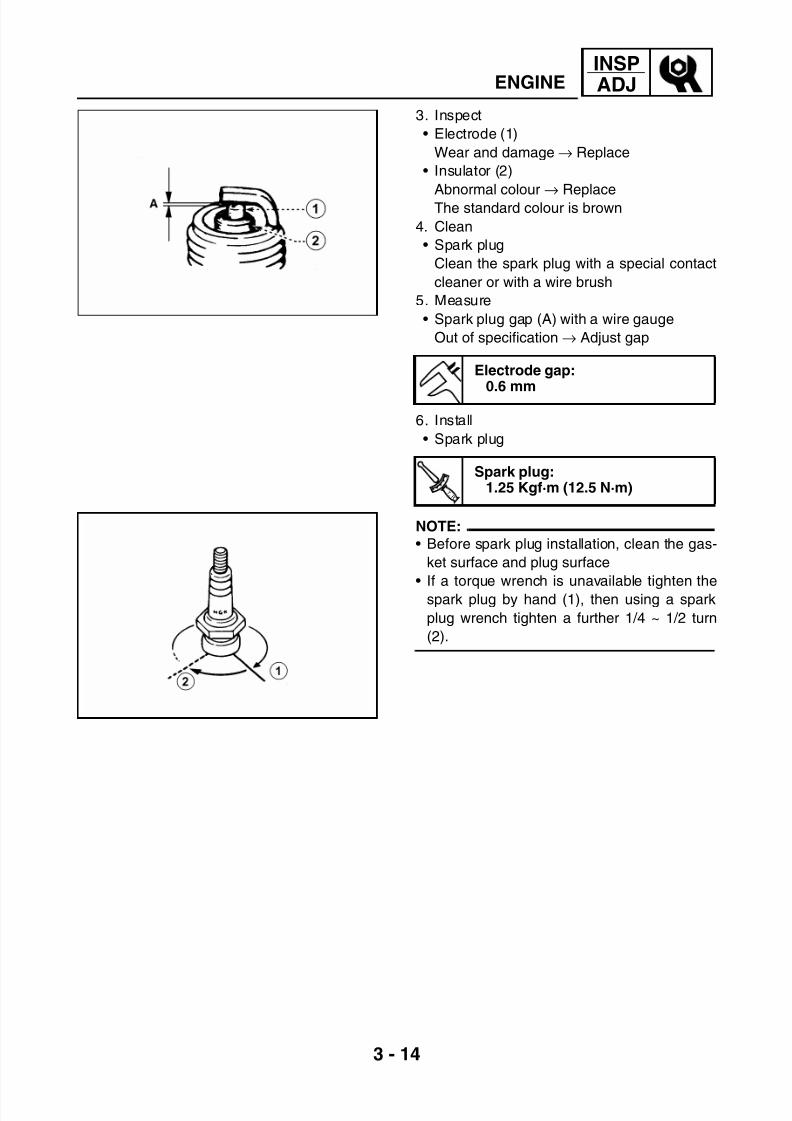
3. Inspect
• Electrode (1)
Wear and damage → Replace
• Insulator (2)
Abnormal colour→
ReplaceThe standard colour is brown
4. Clean
• Spark plug
Clean the spark plug with a special contact
cleaner or with a wire brush
5. Measure
• Spark plug gap (A) with a wire gauge
Out of specification → Adjust gap
6. Install
• Spark plug
NOTE:
• Before spark plug installation, clean the gas-
ket surface and plug surface
• If a torque wrench is unavailable tighten the
spark plug by hand (1), then using a spark
plug wrench tighten a further 1/4 ~ 1/2 turn
(2).
Electrode gap:
0.6 mm
T R .
.
Spark plug:1.25 Kgf·m (12.5 N·m)

7/22/2019 Yamaha xt 125 service manual
http://slidepdf.com/reader/full/yamaha-xt-125-service-manual 57/279
3 - 15
INSPADJENGINE
IGNITION TIMING CHECK
NOTE:
Prior to checking the ignition timing, check all
electrical connections related to the ignition
system. Make sure all connections are tightand free of corrosion and that all ground con-
nections are tight.
1. Remove
• Check plug
2. Install
• Timing light (1)
• Engine tachometer (2) to the spark plug
lead
3. Check
• Ignition timing
*****************************************************
Checking steps
• Start the engine and let it warm up for sev-eral minutes. Let the engine run at the speci-
fied speed
• Visually check the stationary pointer (A) to
verify it is within the correct range (B) indi-
cated on the flywheel.
Incorrect range → Check the ignition system
*****************************************************
NOTE:
Ignition timing is not adjustable
4. Install
• Timing check plug with O-Ring
Timing light:90890-03141
Engine tachometer:90890-06760
Engine idling speed:1300 ~ 1500 rpm
2

7/22/2019 Yamaha xt 125 service manual
http://slidepdf.com/reader/full/yamaha-xt-125-service-manual 58/279
3 - 16
INSPADJENGINE
COMPRESSION PRESSURE
MEASUREMENT
NOTE:
Insufficient compression pressure will result in
performance loss
1. Check
• Valve clearance
Out of specification → Adjust
See “VALVE CLEARANCE ADJUSTMENT”
page 3-9
2. Start the engine and let it warm up for
several minutes
3. Turn off the engine.
4. Remove the spark plug
CAUTION:
Before removing the spark plug, use com-
pressed air to blow away any dirt accumu-
lated in the spark plug well to prevent it
from falling into the cylinder
5. Install
• Compression gauge (1)
6. Check
• Compression pressure
*****************************************************
Measurement steps
• Crank the engine with the throttle wide open
until the reading on the compression gauge
stabilizes
WARNING
Before cranking the engine, ground all
spark pIug leads to prevent sparking.
*****************************************************
Compression gauge:90890-03081
Compression pressure at sealevel:Standard:
1200 KPa (12 Kg/cm2)Minimum value:
1040 KPa (10.4 Kg/cm2)

7/22/2019 Yamaha xt 125 service manual
http://slidepdf.com/reader/full/yamaha-xt-125-service-manual 59/279
3 - 17
INSPADJENGINE
7. Measure
• Compression pressure
If it exceeds the maximum pressure
allowed → Inspect the cylinder head, valve
surfaces and piston crown for carbondeposits
If it is below the minimum pressure→ Squirt
a few drops of oil into the affected cylinder
and measure again
Follow the table below
8. Install
• Spark plug
Compression pressure (with oil appliedinto cylinder)
Measured value Diagnosis
Value increased after
oil added
Worn or damaged
pistonsValue did not
increase
Possible defective
ring, valves, cylinder
head gasket or piston
→ Repair
ENGINE OIL LEVEL INSPECTION
1. Stand the motorcycle on a level surface.
NOTE:
Make sure the motorcycle is upright when
inspecting the oil level
• Start the engine and let it warm up for sev-
eral minutes
• Turn off the engine.
2. Remove the dip stick (1)
Wipe off the dip stick with clean cloth and
reset on the threads of oil filler hole
Then remove the dip stick (oil level gauge)
3. Check
• Engine oil level
Oil level should be between MIN and MAX
marks
Oil level is below the MIN mark → Add oil to
the MAX mark
Recommended engine oil:YAMALUBE 4 or SAE 10W30-SH
MIN
MAX

7/22/2019 Yamaha xt 125 service manual
http://slidepdf.com/reader/full/yamaha-xt-125-service-manual 60/279
3 - 18
INSPADJENGINE
4. Start the engine and let it warm up for
several minutes
5. Turn off the engine.
NOTE:
Wait a few minutes until the oil settles beforeinspecting the oil level
ENGINE OIL CHANGE
1. Stand the motorcycle on a level surface.
2. Start the engine and let it warm up for
several minutes
3. Turn off the engine and place an oil pan
under the engine4. Remove
• Dip stick (oil level gauge)
• Drain plug (1)
• Gasket
5. Drain the crankcase oil
6. Install
• Drain plug (1)
• Dip stick (oil level gauge)
7. Fill
• Oil in the cover
8. Check
• Engine oil level
See “ENGINE OIL LEVEL INSPECTION”
page 3-17
T R .
.
Drain plug:
2.0 Kgf·m (20 N·m)
Oil quantity:1.0 L

7/22/2019 Yamaha xt 125 service manual
http://slidepdf.com/reader/full/yamaha-xt-125-service-manual 61/279
3 - 19
INSPADJENGINE
OIL PRESSURE INSPECTION
1. Remove
• Oil check bolt (1)
2. Start the engine and keep it idling for sev-
eral minutes.
CAUTION:
If no oil comes out after a lapse of one
minute, turn off the engine immediately so
it will not seize.
Tighten
• Oil check bolt (1)
Oil flows out → Oil pressure is good
No oil comes out → Oil pressure is bad
T R .
.
Oil check bolt:0.7 Kgf·m (7 N·m)
CLEANING THE AIR FILTER
1. Stand the motorcycle on a level surface.
2. Remove• Seat
See “SEAT REMOVAL” page 3-2
• Boot (1)
• Air filter case (2)
• Air filter (3)
CAUTION:
Never operate the engine when the air filter
element is not installed. Unfiltered air will
cause rapid wear of engine parts and may
damage the engine. Operating the enginewithout the filter element will also affect the
carburetor tuning, leading to poor engine
performance and possible overheating.
3. Inspect
• Air filter element
Wear and damage → Replace

7/22/2019 Yamaha xt 125 service manual
http://slidepdf.com/reader/full/yamaha-xt-125-service-manual 62/279
3 - 20
INSPADJENGINE
4. Clean
• Air filter element
Use kerosene to clean the element
NOTE:
After cleaning, remove the remaining keroseneby squeezing the element
CAUTION:
Do not twist the filter element when
squeezing it
5. Apply the recommended oil to the entire
surface of the filter and squeeze out excess
oil. The element should be wet not dripping
CAUTION:
Never use gasoline to clean the air filter
element. Such solvent may cause a fire or
an explosion.
6. Install
• Air filter (3)
• Air filter case (2)
• Boot (1)
• Seat
See “SEAT INSTALLATION” page 3-2
MANIFOLD AND INLET SLEEVE
INSPECTION
1. Stand the motorcycle on a level surface.
2. Remove
• Seat
See “SEAT REMOVAL” page 3-23. Check
• Manifold (1)
• Inlet sleeve (2)
Wear and damage → Replace
4. Install
• Seat
See “SEAT INSTALLATION” page 3-2
Recommended oil:YAMALUBE 4 or SAE 10W30-SH
T R .
.
Bolt (3):1.0 Kgf·m (10 N·m)
Clamp (4):0.2 Kgf·m (2 N·m)

7/22/2019 Yamaha xt 125 service manual
http://slidepdf.com/reader/full/yamaha-xt-125-service-manual 63/279
3 - 21
INSPADJENGINE
FUEL LINE INSPECTION
1. Remove
• Side covers
See “TANK PANEL REMOVAL” page 3-2
• Fuel tankSee “FUEL TANK REMOVAL” page 3-3
2. Check
• Fuel hose
• Wear and damage→ Replace
3. Install
• Fuel tank
See “FUEL TANK INSTALLATION” page 3-
3
• Side covers
See “TANK PANEL INSTALLATION” page
3-2
CRANKCASE VENTILATION HOSE
INSPECTION
1. Check
• Crankcase ventilation hose
Wear and damage → Replace
EXHAUST SYSTEM INSPECTION
1. Remove
• Exhaust pipe (1)
• Muffler (2)• Gasket (3)
2. Inspect
• Exhaust pipe (1)
• Muffler (2)
Damage and bends → Replace
• Gasket (3)
Exhaust gas leak → Replace
3. Install
• Gasket (3)
• Exhaust pipe (1)
• Muffler (2)
T R .
.
Muffler bolt (4):4.0 Kgf·m (40 N·m)
Protection bolt (5):0.8 Kgf·m (8 N·m)
Exhaust pipe screw (6):1.0 Kgf·m (10 N·m)

7/22/2019 Yamaha xt 125 service manual
http://slidepdf.com/reader/full/yamaha-xt-125-service-manual 64/279
3 - 22
INSPADJFRAME
FRAMECLUTCH ADJUSTMENT
1. Check
• Clutch lever free play (A)
Out of specification → Adjust
2. Adjust
• Clutch lever free play (A)
*****************************************************
Adjustment steps
• Loosen lock nut (1).
• Turn the adjuster (2) clockwise or counter-clockwise until the specified free play is
obtained.
• Tighten lock nut (1).
*****************************************************
Free play at the end of the clutchlever:
10 ~ 15 mm
Turning clockwise → Clearance is
increased
Turning counterclockwise → Clearance
is decreased
FRONT BRAKE FLUID LEVEL INSPECTION
1. Stand the motorcycle on a level surface.
NOTE:
• Position the motorcycle on a suitable stand.
• During check, make sure that the upper part
of the brake pump is in horizontal position
1. Check
• Brake fluid level
Fluid level is under “LOWER” level line (1)
→ Add the recommended brake fluid to the
proper level
CAUTION:
Brake fluid may damage painted surfaces
and plastic parts. Always clean up split
fluid immediately.
Recommended brake fluid:DOT N°4

7/22/2019 Yamaha xt 125 service manual
http://slidepdf.com/reader/full/yamaha-xt-125-service-manual 65/279
3 - 23
INSPADJFRAME
WARNING
• Use only the designated quality brake
fluid: otherwise, the rubber seals may
deteriorate, causing leakage and poor
brake performance.• Refill with the same type of brake fluid;
mixing fluids may result in a harmful
chemical reaction and lead to poor perfor-
mance.
• Be careful that water does not enter the
master cylinder when refilling. Water will
significantly lower the boiling point of the
fluid and may result in vapour lock.
FRONT BRAKE PAD INSPECTION
1. Activate the brake lever
2. Check
• Brake pad
Pad thickness (A) lower than the minimum
value→
Replace
See “BRAKE PAD REPLACEMENT” page 6-7
Minimum pad thickness:2 mm
XT 125 R
XT 125 X

7/22/2019 Yamaha xt 125 service manual
http://slidepdf.com/reader/full/yamaha-xt-125-service-manual 66/279
3 - 24
INSPADJFRAME
AIR BLEEDING (FRONT BRAKE SYSTEM)
WARNING
Bleed the brake system if:
• The system has been disassembled
• A brake hose has been loosened orremoved
• The brake fluid is very low
• The brake operation is faulty
A dangerous loss of braking performance
may occur if the brake system is not pro-
perly bled
1. Bleed
• Braking system
*****************************************************Air bleeding steeps
(a)Fill up the brake master cylinder reservoir
until you reach the maximum level
(b)Install the diaphragm, check that no liquid
flows out and that the master cylinder re-
servoir is not filled too much.
(c)Connect the clear plastic tube (1) tightly to
the caliper bleed screw (2)
(d)Place the other end of the tube into a con-
tainer.
(e)Slowly apply the brake lever or pedal se-veral times
(f) Pull the lever in or push down on the pedal.
Hold the lever or pedal in position
(g)Loosen the bleed screw and allow the lever
or pedal to travel towards its limit
(h)Tighten the bleed screw when the lever or
pedal limit has been reached; then release
the lever or pedal
(l) Repeat steps (e) to (h) until all of the air
bubbles have been removed from the sys-
tem.
NOTE:
If the bleeding is difficult, it may be necessary
to let the brake fluid system stabilize for a few
hours. Repeat the bleeding procedure when
the tiny bubbles in the system have disap-
peared.
T R .
.
Bleed screw:
0.6 Kgf·m (6 N·m)

7/22/2019 Yamaha xt 125 service manual
http://slidepdf.com/reader/full/yamaha-xt-125-service-manual 67/279
3 - 25
INSPADJFRAME
(m)Add brake fluid to proper level.
WARNING
After bleeding, check the correct operation
of the braking system.
*****************************************************
Recommended brake fluid:DOT N°4
REAR BRAKE PEDAL ADJUSTMENT
1. Stand the motorcycle on a level surface.
2. Check
• Brake pedal free play (A)
Out of specification → Adjust
3. Adjust
• Brake pedal free play (A)
*****************************************************
Adjustment steps
• Loosen lock nut (1).
• Turn adjusting screw (2) clockwise and
counerclockwise until you reach the recom-
mended play
• Tighten lock nut (1).
*****************************************************
Brake pedal free play:12 ~ 15 mm
Turning clockwise → The pedal free play
is increased
Turning counterclockwise → The pedal
free play is decreased
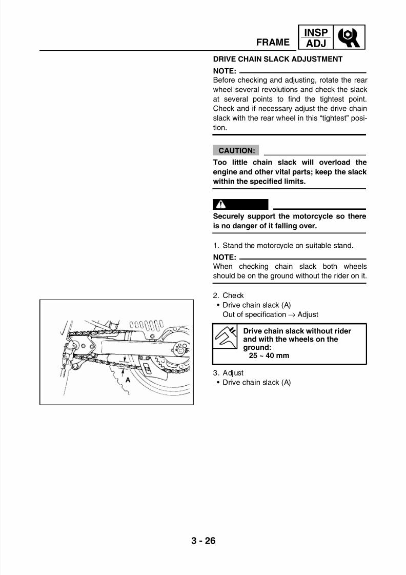
7/22/2019 Yamaha xt 125 service manual
http://slidepdf.com/reader/full/yamaha-xt-125-service-manual 68/279
3 - 26
INSPADJFRAME
DRIVE CHAIN SLACK ADJUSTMENT
NOTE:
Before checking and adjusting, rotate the rear
wheel several revolutions and check the slack
at several points to find the tightest point.Check and if necessary adjust the drive chain
slack with the rear wheel in this “tightest” posi-
tion.
CAUTION:
Too little chain slack will overload the
engine and other vital parts; keep the slack
within the specified limits.
WARNING
Securely support the motorcycle so there
is no danger of it falling over.
1. Stand the motorcycle on suitable stand.
NOTE:
When checking chain slack both wheels
should be on the ground without the rider on it.
2. Check
• Drive chain slack (A)
Out of specification → Adjust
3. Adjust
• Drive chain slack (A)
Drive chain slack without riderand with the wheels on theground:
25 ~ 40 mm

7/22/2019 Yamaha xt 125 service manual
http://slidepdf.com/reader/full/yamaha-xt-125-service-manual 69/279
3 - 27
INSPADJFRAME
*****************************************************Adjustment steps
• Loosen nut (1).
• Loosen lock nut (2).
• Turn adjusting screw (3) clockwise and
counerclockwise to adjust the chain play.
NOTE:
Carry out the operation in the same way on
both sides to keep the pin aligned. Use gradu-
ated scale (4) to check alignment.
• Tighten lock nut (2).
• Tighten nut (1).
Turning clockwise → The chain slack is
increased
Turning counterclockwise → The chain
slack is decreased
T R .
.
Axle nut:8.5 Kgf·m (85 N·m)
DRIVE CHAIN LUBRICATION
The chain consists of many parts that workagainst each other. If the chain is not main-
tained properly, it will wear out rapidly, there-
fore, it is recommended to periodically service
the chain. This service is specially necessary
when riding in dusty conditions.
Recommended lubricant SAE20W50 or chain lubricants suit-able for “O-Ring” chains.
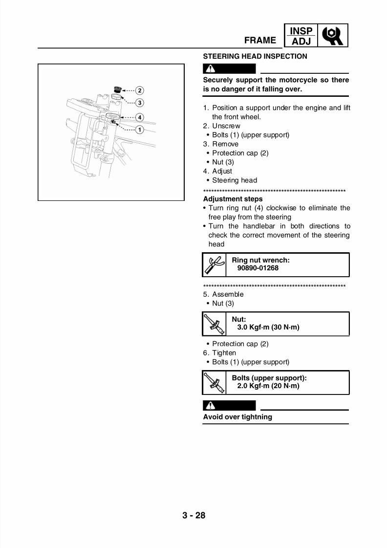
7/22/2019 Yamaha xt 125 service manual
http://slidepdf.com/reader/full/yamaha-xt-125-service-manual 70/279
3 - 28
INSPADJFRAME
STEERING HEAD INSPECTION
WARNING
Securely support the motorcycle so there
is no danger of it falling over.
1. Position a support under the engine and lift
the front wheel.
2. Unscrew
• Bolts (1) (upper support)
3. Remove
• Protection cap (2)
• Nut (3)
4. Adjust
• Steering head
*****************************************************Adjustment steps
• Turn ring nut (4) clockwise to eliminate the
free play from the steering
• Turn the handlebar in both directions to
check the correct movement of the steering
head
*****************************************************5. Assemble
• Nut (3)
• Protection cap (2)
6. Tighten
• Bolts (1) (upper support)
WARNING
Avoid over tightning
Ring nut wrench:90890-01268
T R .
.
Nut:3.0 Kgf·m (30 N·m)
T R .
.
Bolts (upper support):
2.0 Kgf·m (20 N·m)
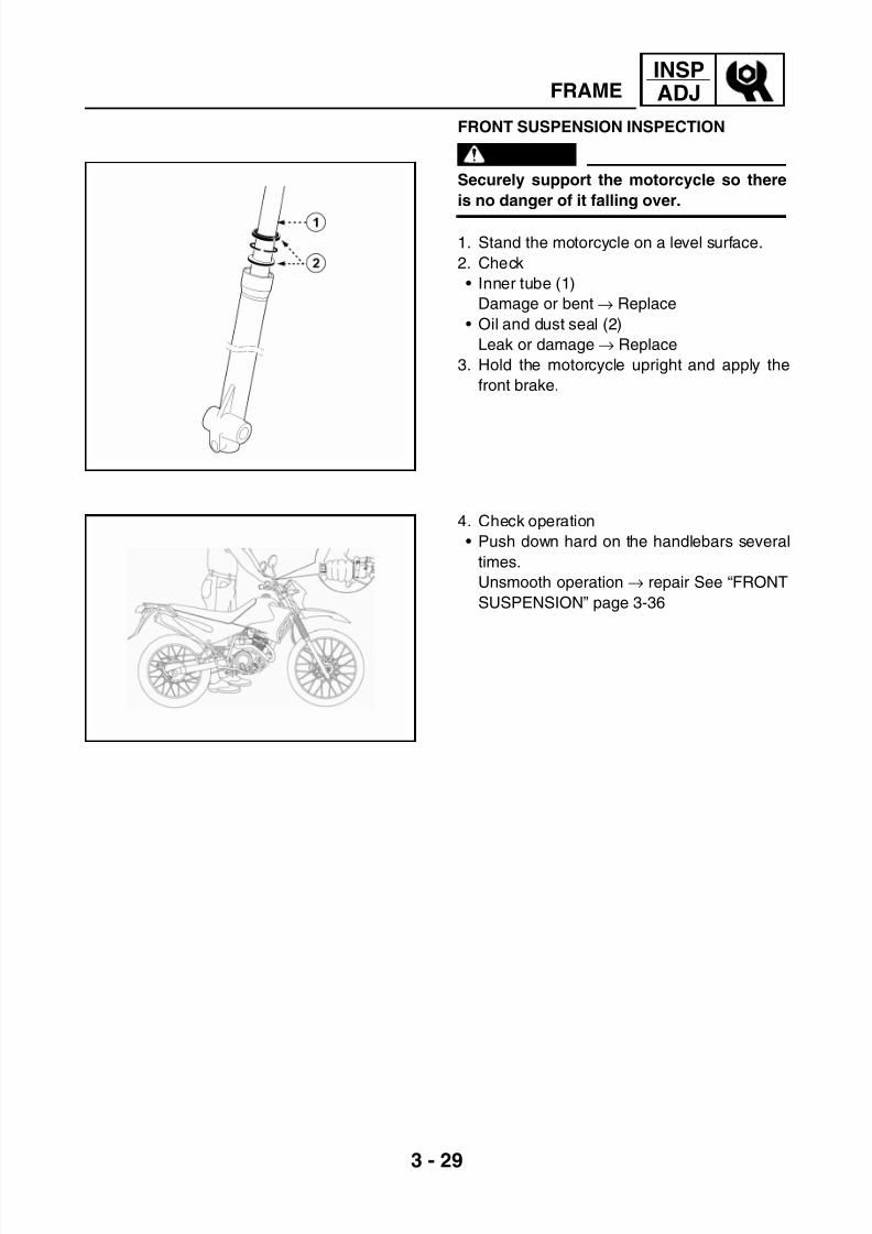
7/22/2019 Yamaha xt 125 service manual
http://slidepdf.com/reader/full/yamaha-xt-125-service-manual 71/279
3 - 29
INSPADJFRAME
FRONT SUSPENSION INSPECTION
WARNING
Securely support the motorcycle so there
is no danger of it falling over.
1. Stand the motorcycle on a level surface.
2. Check
• Inner tube (1)
Damage or bent → Replace
• Oil and dust seal (2)
Leak or damage → Replace
3. Hold the motorcycle upright and apply the
front brake.
4. Check operation
• Push down hard on the handlebars several
times.
Unsmooth operation → repair See “FRONT
SUSPENSION” page 3-36
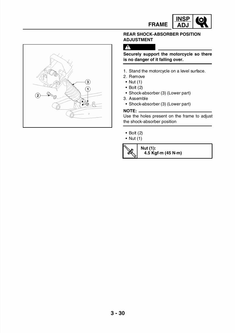
7/22/2019 Yamaha xt 125 service manual
http://slidepdf.com/reader/full/yamaha-xt-125-service-manual 72/279
3 - 30
INSPADJFRAME
REAR SHOCK-ABSORBER POSITION
ADJUSTMENT
WARNING
Securely support the motorcycle so there
is no danger of it falling over.
1. Stand the motorcycle on a level surface.
2. Remove
• Nut (1)
• Bolt (2)
• Shock-absorber (3) (Lower part)
3. Assemble
• Shock-absorber (3) (Lower part)
NOTE:
Use the holes present on the frame to adjustthe shock-absorber position
• Bolt (2)
• Nut (1)
T R .
.
Nut (1):4.5 Kgf·m (45 N·m)

7/22/2019 Yamaha xt 125 service manual
http://slidepdf.com/reader/full/yamaha-xt-125-service-manual 73/279
3 - 31
INSPADJFRAME
TYRE INSPECTION
1. Measure
• Tyre inflation pressure
Out of specification → Adjust
WARNING• Tyre inflation pressure should only be
checked and adjusted when the tyre tem-
perature equals the ambient air tempera-
ture. Tyre inflation pressure and
suspension must be adjusted according
to the total weight of the cargo, rider, pas-
senger and accessories (fairing, saddle-
bags, etc. if approved for this model).
NEVER OVERLOAD THE MOTORCYCLE
• Operation of an overloaded motorcyclecould cause tyre damage, accident or
injury.
* Load is the total weight of the cargo, rider,passenger and accessories.
2. Inspect
• Tyre surfaces
Wear and damage → Replace
(1) Tread depth
(2) Side wall(3) Wear indicator
Tyre inflation
pressureFront Rear
Up to 90 kg load 1.8 bar
(26.1 psi)
1.9 bar
(27.6 psi)
With maximum
load 178 kg
2.0 bar
(29.0 psi)
2.1 bar
(30.5 psi)
Minimum tyre tread depth:1 mm

7/22/2019 Yamaha xt 125 service manual
http://slidepdf.com/reader/full/yamaha-xt-125-service-manual 74/279
3 - 32
INSPADJFRAME
WARNING
• It is dangerous to ride with a worn-out
tyre. When the tyre tread begins to show
signs of wear, replace the tyre imme-
diately.• Patching a punctured tube is not recom-
mended. If it is absolutely necessary to
do so, use great care and replace the tube
as soon as possible with a good quality
replacement tube.
• Do not use Tubeless tyres on a wheel
designed for Tube Type tires only. Tyre
failure and personal injury may result
from sudden deflation.
• Be sure to install the correct tube when using
Tube Type tyres.
WARNING
After mounting a tyre, ride conservatively
for a while to give the tire time to seat itself
properly in the rim. Failure to do so could
lead to an accident with possible injury to
the rider or damage to the motorcycle.
3. After a tyre repair or replacement, be sure
to tighten the valve stem locknut (1) accord-
ing to the correct tightening torque.
Tube Type wheel → Tube Type tyre only
Tubeless type wheel → Tube type ortubeless tyre.
T R .
.
Valve locknut (1):0.3 Kgf·m (3 N·m)

7/22/2019 Yamaha xt 125 service manual
http://slidepdf.com/reader/full/yamaha-xt-125-service-manual 75/279
3 - 33
INSPADJFRAME
SPOKE INSPECTION AND TIGHTENING
1. Inspect
• Wheel spokes
Damage and bends → Replace
Loose spoke→
Retighten2. Tighten
• Loose spoke
NOTE:
Be sure to tighten the spokes before and after
break-in.
T R .
.
Wheel spokes:0.3 Kgf·m (3 N·m)
WHEEL INSPECTION
1. Inspect
• Wheels
Damage or bent → Replace
NOTE:
Always balance the wheel when a tyre orwheel has been changed or replaced.
WARNING
Never attempt to make any repairs to the
wheel.

7/22/2019 Yamaha xt 125 service manual
http://slidepdf.com/reader/full/yamaha-xt-125-service-manual 76/279
3 - 34
INSPADJFRAME
CABLE INSPECTION AND LUBRICATION
WARNING
Damaged cable sheaths may cause corro-
sion and interfere with the cable move-
ment. An unsafe condition may result soreplace such cable as soon as possible.
1. Check
• Cable auta sheaths
Bends and wear → Replace
2. Check
Cable operation → Unsmooth operation
NOTE:
Hold the cable end upright and pour a few
drops of lubricant into cable sheaths or use a
suitable lubing device.
Lubricate with engine oil or a suit-able cable lubricant
LEVER AND PEDAL LUBRICATION
Lubricate the joints with grease

7/22/2019 Yamaha xt 125 service manual
http://slidepdf.com/reader/full/yamaha-xt-125-service-manual 77/279
3 - 35
INSPADJELECTRIC SYSTEM
ELECTRIC SYSTEMBATTERY INSPECTION
1. Remove
• Seat
See “SEAT REMOVAL” page 3-22. Inspect
• Battery terminals
Dirt → Clean with a wire brush
Poor connection → connect properly
NOTE:
After cleaning the terminals, apply a light coat
of grease to the terminals.
*****************************************************Replace the battery if:
Battery voltage will not rise to a specific value
*****************************************************
CAUTION:
Always charge a new battery before using
it to ensure maximum performance.
WARNING
• Battery electrolyte is dangerous. It con-
tains sulphuric acid which is poisonous
and highly caustic. Always follow these
preventive measures.
• Avoid bodily contact with electrolyte as it
can cause severe burns and permanent
eye injury.
• Wear protective eye gear when handling
or working near batteries.
Antidote (EXTERNAL)• Skin - Flush with water
• Eyes - Flush with water for 15 minutes
and get immediate medical attention.
Antidote (INTERNAL)
• Drink large quantities of water or milk fol-
lowed with milk of magnesia, beaten egg
or vegetable oil. Get immediate medical
attention.
D A N G
E R
A C I D

7/22/2019 Yamaha xt 125 service manual
http://slidepdf.com/reader/full/yamaha-xt-125-service-manual 78/279
3 - 36
INSPADJELECTRIC SYSTEM
Batteries generate explosive hydrogen gas.
Always follow these preventive measures.
• Charge batteries in a well - ventilated area
• Keep batteries away from fire, sparks or
open flames (e.g., welding equipment,lighted cigarettes, etc.)
• DO NOT SMOKE when charging or
handling batteries.
• KEEP BATTERIES AND ELECTROLYTE
OUT OF REACH OF CHILDREN.
3. Install
• Battery (1)
4. Connect
• Battery leads (2-3)
CAUTION:
Connect the positive lead (2) first and then
connect the negative lead (3).
• Seat
See “SEAT INSTALLATION” page 3-2
FUSE INSPECTION 10A
CAUTION:
Always turn off the main switch when
checking or replacing the fuse. Otherwise,
a short circuit may occur.
1. Remove
• SeatSee “SEAT REMOVAL” page 3-2
2. Inspect
• Fuse (1)

7/22/2019 Yamaha xt 125 service manual
http://slidepdf.com/reader/full/yamaha-xt-125-service-manual 79/279
3 - 37
INSPADJELECTRIC SYSTEM
*****************************************************Inspection steps
• Connect the Multimeter to the fuse and
check it for continuity
NOTE:Set the Multimeter selector to Ω × 1 position
• If the Multimeter is indicated at “∞”, replace
the fuse
*****************************************************
3. Replace
• Blown fuse
*****************************************************
Replacement steps
• Install a new fuse with the proper current
rating.
• Turn on switches to verify operation of
related electrical devices.
• If the fuse blows again immediately, check
the electrical circuit.
WARNING
Never use a fuse with a rating other than
that specified. Never use other materials in
place of a fuse. An improper fuse may
cause extensive damage to the electrical
system, malfunction of lighting and ignition
systems and could possibly cause a fire.
*****************************************************
4. Install
• Seat
See “SEAT INSTALLATION” page 3-2
Multimeter:90890-01312

7/22/2019 Yamaha xt 125 service manual
http://slidepdf.com/reader/full/yamaha-xt-125-service-manual 80/279
3 - 38
INSPADJELECTRIC SYSTEM
HEADLIGHT BEAM ADJUSTMENT
1. Adjust
• Headlight beam (vertical)
To raise
the beam Turn adjuster (1) clockwise
To lower
the beam
Turn adjuster (1)
counterclockwise
CHANGING FRONT HEADLIGHT BULBS
1. Remove
• Headlight holder
See “HEADLIGHT HOLDER REMOVAL”
page 3-4
2. Disconnect
• Connectors (1-2)
3. Remove
• Boot (3)
4. Replace
• Damaged bulbs (4-5)
WARNING
Keep flammable products and your hands
away from the bulb while it is on, it will be
hot. Do not touch the bulb unit it cools
down.
5. Install
• Bulbs (new)
CAUTION:
Avoid touching glass part of bulb. Also
keep it away from oil otherwise, trans-
parency of glass, bulb life and illumines
flux will be adversely affected. If oil gets on
bulb, clean it with a cloth moistened thor-
oughly with alcohol or lacquer.
• Boot (3)

7/22/2019 Yamaha xt 125 service manual
http://slidepdf.com/reader/full/yamaha-xt-125-service-manual 81/279
3 - 39
INSPADJELECTRIC SYSTEM
6. Connect
• Connectors (1-2)
7. Install
• Headlight holder
See “HEADLIGHT HOLDER INSTALLA-TION” page 3-5
REAR TAIL /BRAKE LIGHT BULB
REPLACEMENT
1. Remove
• Rear cover
See “TAIL COWLING REMOVAL” page 3-7
2. Unscrew
• Bolts (1)
3. Remove• Rear glass (2)
4. Replace
• Damaged bulb (3)
WARNING
Keep flammable products and your hands
away from the bulb while it is on, it will be
hot. Do not touch the bulb unit it cools
down.
5. Install• Bulb (new)
CAUTION:
Avoid touching glass part of bulb. Also
keep it away from oil otherwise, trans-
parency of glass, bulb life and illumines
flux will be adversely affected. If oil gets on
bulb, clean it with a cloth moistened
thoroughly with alcohol or lacquer.
• Rear glass (2)
6. Screw
• Bolts (1)
7. Install
• Rear cover
See “TAIL COWLING INSTALLATION”
page 3-7
*****************************************************

7/22/2019 Yamaha xt 125 service manual
http://slidepdf.com/reader/full/yamaha-xt-125-service-manual 82/279
ENG
CHAPTER 4
ENGINE
ENGINE REMOVAL ........................................................................................4-1FUEL TANK...............................................................................................4-1ENGINE OIL .............................................................................................. 4-1BATTERY.................................................................................................. 4-1CARBURETOR .........................................................................................4-1CLUTCH CABLE .......................................................................................4-2TRANSMISSION CHAIN ........................................................................... 4-2MUFFLER..................................................................................................4-2SHIFT PEDAL ...........................................................................................4-2SUMP COVER ..........................................................................................4-2CDI MAGNETO CONNECTORS...............................................................4-3
ENGINE REMOVAL ..................................................................................4-3
ENGINE DISASSEMBLY ................................................................................4-5CYLINDER HEAD, CYLINDER AND PISTON ..........................................4-5CDI MAGNETO .........................................................................................4-8
CLUTCH .................................................................................................... 4-9OIL PUMP ............................................................................................... 4-11KICK STARTER ......................................................................................4-12SHIFT SHAFT .........................................................................................4-13ENGINE COVER.....................................................................................4-13BALANCER, TRANSMISSION AND SHIFTER.......................................4-15
CRANKSHAFT ........................................................................................4-16ROCKER ARMS, CAMSHAFT AND VALVES ........................................4-16
INSPECTION AND REPAIR..........................................................................4-19CYLINDER HEAD ...................................................................................4-19
VALVE SEATS ........................................................................................4-20VALVE SPRINGS AND VALVES ............................................................ 4-22CAMSHAFT INSPECTION......................................................................4-23ROCKER ARMS AND ROCKER ARM SHAFTS INSPECTION..............4-24TIMING CHAIN, SPROCKETS AND CHAIN GUIDES ............................ 4-25TIMING CHAIN TENSIONER..................................................................4-26
CYLINDER AND PISTON ....................................................................... 4-26PISTON RING INSPECTION .................................................................. 4-27PISTON PIN INSPECTION ..................................................................... 4-28CRANKSHAFT ........................................................................................4-29BALANCER INSPECTION ...................................................................... 4-31CLUTCH HOUSING INSPECTION ........................................................ 4-31CLUTCH INSPECTION ...........................................................................4-31PUSH ROD INSPECTION.......................................................................4-33FORK AND SHIFTER INSPECTION.......................................................4-33KICK STARTER INSPECTION .............................................................. 4-35OIL PUMP INSPECTION ........................................................................4-35
OIL PASSAGE INSPECTION(RIGHT CRANKCASE HALF COVER)...................................................4-36ENGINE COVER.....................................................................................4-36BEARINGS AND OIL SEALS.................................................................. 4-37CIRCLIPS AND WASHERS .................................................................... 4-37
7/22/2019 Yamaha xt 125 service manual
http://slidepdf.com/reader/full/yamaha-xt-125-service-manual 83/279
ENG
ENGINE ASSEMBLY AND ADJUSTMENTS................................................4-38VALVES, ROCKER ARMS AND CAMSHAFT ........................................ 4-38VALVES AND VALVE SPRINGS INSTALLATION..................................4-39ROCKER ARM AND CAMSHAFT INSTALLATION ................................ 4-40CRANKSHAFT AND BALANCER SHAFT ..............................................4-42
TRANSMISSION .....................................................................................4-44SHIFTER ................................................................................................. 4-45TRANSMISSION, SHIFT FORK AND SHIFTER INSTALLATION ..........4-46CRANKCASE ..........................................................................................4-48CRANKCASE (LEFT) ..............................................................................4-49SHIFT SHAFT AND KICK STARTER......................................................4-50SEGMENT AND SHIFT SHAFT ..............................................................4-51KICK STARTER INSTALLATION............................................................4-52CLUTCH, CLUTCH HOUSING AND OIL PUMP.....................................4-53OIL PUMP INSTALLATION ....................................................................4-54CLUTCH GEAR INSTALLATION ............................................................ 4-54
CLUTCH INSTALLATION ....................................................................... 4-55CDI MAGNETO .......................................................................................4-58
STARTER GEAR INSPECTION..............................................................4-59CDI MAGNETO AND STARTER GEAR..................................................4-59CYLINDER AND PISTON ....................................................................... 4-61CYLINDER HEAD ...................................................................................4-62DRIVE GEAR AND TIMING CHAIN ........................................................ 4-63PISTON RINGS, PISTON AND CYLINDER INSTALLATION.................4-64CYLINDER HEAD INSTALLATION.........................................................4-65ENGINE MOUNTING ..............................................................................4-69

7/22/2019 Yamaha xt 125 service manual
http://slidepdf.com/reader/full/yamaha-xt-125-service-manual 84/279
4 - 1
ENG
ENGINEENGINE REMOVAL
NOTE:
It is not necessary to remove the engine to
remove the following parts
• Cylinder head
• Cylinder
• Piston
• Clutch
• CDI magneto
FUEL TANK
1. Remove
• Seat
See “SEAT REMOVAL” page 3-2
• Fuel tank
See “FUEL TANK REMOVAL” page 3-3
ENGINE OIL
1. Drain
• Engine oil
See “ENGINE OIL CHANGE” page 3-18
BATTERY
1. Remove
• Battery
CAUTION:
Disconnect the negative lead (1) first and
then disconnect the positive lead (2) from
the battery.
CARBURETOR
1. Remove
• Carburetor
See “REMOVAL” page 5-2
NOTE:
Cover the carburetor with a clean rag to pre-
vent dirt or foreign material from entering the
carburetor.
ENGINE REMOVAL

7/22/2019 Yamaha xt 125 service manual
http://slidepdf.com/reader/full/yamaha-xt-125-service-manual 85/279
4 - 2
ENGENGINE REMOVAL
CLUTCH CABLE
1. Remove
• Clutch cable
*****************************************************
Removal steps• Loosen the locknut (1) of the lever side
• Turn the adjuster (2) enough to free the
clutch cable
• Unhook the cable end of the engine side
*****************************************************
TRANSMISSION CHAIN
1. Remove• Transmission chain
See “CHAIN REMOVAL” page 6-32
MUFFLER
1. Remove
• Muffler
See “EXHAUST SYSTEM INSPECTION”
page 3-21
SHIFT PEDAL
1. Remove
• Shift pedal (1)
SUMP COVER
1. Remove
• Sump cover
See “ENGINE SUMP COVER REMOVAL”
page 3-6

7/22/2019 Yamaha xt 125 service manual
http://slidepdf.com/reader/full/yamaha-xt-125-service-manual 86/279
4 - 3
ENGENGINE REMOVAL
CDI MAGNETO CONNECTORS
1. Disconnect
• 4-pin connector (1)
• 2-pin connector (2)
• Spark plug cap (3)
• Starter motor cable (4)
ENGINE REMOVAL
Place a suitable stand beneath the frame and
engine.
WARNING
Securely support the motorcycle so there
is no danger of it falling over.
1. Remove
• Nuts (1)
• Bolts (2)
• Brackets (3)
2. Remove
• Nut (4)
• Bolt (5)

7/22/2019 Yamaha xt 125 service manual
http://slidepdf.com/reader/full/yamaha-xt-125-service-manual 87/279
4 - 4
ENGENGINE REMOVAL
3. Remove
• Nut (6)
• Bolt (7)
4. Remove
• EngineNOTE:
Remove the engine from the right side of the
motorcycle
5. Remove
• Nuts (8)
• Bolts (9)
• Rear stand (10)

7/22/2019 Yamaha xt 125 service manual
http://slidepdf.com/reader/full/yamaha-xt-125-service-manual 88/279
4 - 5
ENGENGINE DISASSEMBLY
ENGINE DISASSEMBLYCYLINDER HEAD, CYLINDER AND PISTON
NOTE:
With engine mounted, the cylinder head, cam-
shaft and cylinder can be checked by remov-ing the following parts:
• Seat
• Side covers
• Fuel tank
• Exhaust pipe
• Carburetor
• Clutch cable
• Spark plug lead
• Upper engine stand
1. Remove
• Spark plug
• Intake manifold (1)
2. Remove
• Timing check plug (with O-Ring) (1)
• Center plug (with O-Ring) (2)
3. Remove
• Valve cover (with O-Ring)
• Cylinder head side cover (with O-Ring)
4. Align
• Slit (a) on the magneto with stationary
pointer (b) on the cover
NOTE:Turn the crankshaft counter-clockwise with a
wrench.

7/22/2019 Yamaha xt 125 service manual
http://slidepdf.com/reader/full/yamaha-xt-125-service-manual 89/279
4 - 6
ENGENGINE DISASSEMBLY
*****************************************************
TDC alignment step
• Turn the crankshaft counter-clockwise until
the slit (a) matches the stationary pointer (b).
• Align the slit (c) of the drive gear with the sta-tionary pointer (d) of the cylinder head. In this
way the piston will be at the top dead centre
(TDC).
NOTE:
• Check that the piston is at TDC on the com-
pression stroke.
• If not, give the crankshaft one counterclock-
wise turn.
*****************************************************
5. Remove
• Bolt (timing chain tensioner) (1)
• Timing chain tensioner assembly (2)
6. Remove
• Bolt (drive gear) (1)
• Special washer (drive gear) (2)
NOTE:
Fasten a safety wire (3) to the timing chain to
prevent it from falling into the crankcase cavity.
7. Remove
• Bolts (cylinder head)
• Cylinder head
NOTE:
• Loosen the bolts by 1/4 turns each and
remove them after all are loosened.
• Loosen the bolts starting with the lowest
number one.
• The embossed numbers in the cylinder headdesignate the tightening sequence.

7/22/2019 Yamaha xt 125 service manual
http://slidepdf.com/reader/full/yamaha-xt-125-service-manual 90/279
4 - 7
ENGENGINE DISASSEMBLY
8. Remove
• Timing chain guide (exhaust side) (1)
• Dowel pins (2)
• Gasket (cylinder head) (3)
• Bolts (cylinder head)• Clutch cable holder
• Cylinder
9. Remove
• Dowel pins (1)
• Gasket (cylinder) (2)
10. Remove
• Piston pin circlip (1)
• Piston pin (2)
• Piston (3)
NOTE:
• Before removing the piston pin circlip, cover
the crankcase with a clean rag to prevent
any object from falling into the crankcase
cavity.
• Before removing the piston pin, deburr the
circlip grooves and pin hole area. If the pis-ton pin is still difficult to remove, use the pis-
ton pin puller.
Piston pin puller:90890-01304

7/22/2019 Yamaha xt 125 service manual
http://slidepdf.com/reader/full/yamaha-xt-125-service-manual 91/279
4 - 8
ENGENGINE DISASSEMBLY
CDI MAGNETO
NOTE:
The CDI magneto can be removed while the
engine is mounted by removing the shift pedal.
1. Remove
• Crankcase cover (left)
• Neutral switch lead
• Nut (magneto) (1)
• Washer (2)
NOTE:
Hold the magneto with a rotor holder while
loosening the magneto nut.
2. Remove
• CDI magneto (1)
• Key
NOTE:
• Remove the CDI magneto with the rotor
puller (2).
• Center the rotor puller over the CDI mag-
neto. Make sure after installing the holding
bolts that the clearance between the puller
and the flywheel is the same everywhere. If
necessary, one holding bolt may be turned
out slightly to adjust the puller’s position.
CAUTION:
Cover the crankshaft tip with the wrench
for protection.
3. Remove
• Starter gear
• Washer
4. Remove
• Plate (2)
• Starter gear (1)
Rotor holder:90890-01701
Rotor puller:90890-01362

7/22/2019 Yamaha xt 125 service manual
http://slidepdf.com/reader/full/yamaha-xt-125-service-manual 92/279
4 - 9
ENGENGINE DISASSEMBLY
5. Remove
• Timing chain guide (1)
• Timing chain (2)
CLUTCH
NOTE:
The clutch assembly can be removed while the
engine is mounted.
Remove the following parts to carry out this
operation
• Footrest
• Shift lever
• Kick starter
1. Remove
• Crankcase cover (right)
NOTE:
Loosen the bolts in a crisscross pattern.
2. Remove
• Gasket (1)
• Dowel pins (2)

7/22/2019 Yamaha xt 125 service manual
http://slidepdf.com/reader/full/yamaha-xt-125-service-manual 93/279
4 - 10
ENGENGINE DISASSEMBLY
3. Remove
• Pressure plate bolts (1)
• Clutch springs (2)
• Pressure plates (3)
• Friction plates (4)• Clutch plate (5)
NOTE:
Loosen the pressure plate bolts in a crisscross
pattern
4. Remove
• Push rod (6)
• Ball (7)
5. Unscrew
• Nut (clutch boss) (1)
NOTE:
• Straighten the lock washer tab (2).
• Loosen the hub nut (1) while holding the
clutch hub with a universal clutch holder (3).
6. Remove
• Clutch boss nut (1)
• Lock washer (2)
• Clutch boss (3)
• Spacer (4)
• Clutch housing (5)
• Spacer (6)
• Washer (7)
Universal clutch holder:90890-04086

7/22/2019 Yamaha xt 125 service manual
http://slidepdf.com/reader/full/yamaha-xt-125-service-manual 94/279
4 - 11
ENGENGINE DISASSEMBLY
7. Unscrew
• Nut (1)
NOTE:
• Place a folded aluminium plate between the
teeth of the primary drive gear and the teethof the clutch housing.
• Take care not to damage the gear teeth.
8. Remove
• Nut
• Special washer
• Primary drive gear (1)
• Key (2)
• Rotary filter (3)
OIL PUMP
NOTE:
The oil pump can be removed while the engine
is mounted.
Remove the following parts to carry out this
operation
• Clutch
• Rotary filter
1. Remove
• Bolt with washer (oil pump) (1)
• Oil pump assembly (2)
• Oil suction screen

7/22/2019 Yamaha xt 125 service manual
http://slidepdf.com/reader/full/yamaha-xt-125-service-manual 95/279
4 - 12
ENGENGINE DISASSEMBLY
KICK STARTER
NOTE:
The kick starter can be removed while the
engine is mounted.
Remove the following parts to carry out thisoperation
• Exhaust pipe
• Bracket
• Brake pedal
• Shift pedal
• Clutch
1. Remove
• Circlip (1)
• Flat washer (2)
• Starter gear (3)
• Special washer
• Seeger ring
2. Remove• Return spring (1)
• Kick starter assembly (2)
• Flat washer (3)
• Seeger ring
• Kick starter disassembly
3. Remove
• Spacer (1)
• Return spring (2)
• Washer (3)
• Starter gear (4)
• Circlip (5)
• Kick axle (6)
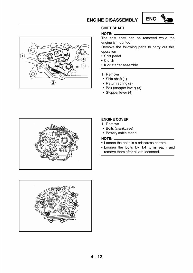
7/22/2019 Yamaha xt 125 service manual
http://slidepdf.com/reader/full/yamaha-xt-125-service-manual 96/279
4 - 13
ENGENGINE DISASSEMBLY
SHIFT SHAFT
NOTE:
The shift shaft can be removed while the
engine is mounted
Remove the following parts to carry out thisoperation
• Shift pedal
• Clutch
• Kick starter assembly
1. Remove
• Shift shaft (1)
• Return spring (2)
• Bolt (stopper lever) (3)
• Stopper lever (4)
ENGINE COVER
1. Remove
• Bolts (crankcase)
• Battery cable stand
NOTE:
• Loosen the bolts in a crisscross pattern.• Loosen the bolts by 1/4 turns each and
remove them after all are loosened.

7/22/2019 Yamaha xt 125 service manual
http://slidepdf.com/reader/full/yamaha-xt-125-service-manual 97/279
4 - 14
ENGENGINE DISASSEMBLY
2. Remove
• Segment bolts
• Use a wrench Torx T-30
3. Remove
• Crankcase half (right)
NOTE:Place the engine with the left crankcase half
turned downwards and put in a screwdriver in
the crankcase separating grooves (a).
CAUTION:
• Do not use the screwdriver except in the
places shown.
• The left crankcase half should be under.
• Separate the crankcase halves after
removing the segment and the axle cir-
clip.
• Do not damage the mating surfaces of the
crankcase halves.
4. Remove
• Dowel pins

7/22/2019 Yamaha xt 125 service manual
http://slidepdf.com/reader/full/yamaha-xt-125-service-manual 98/279
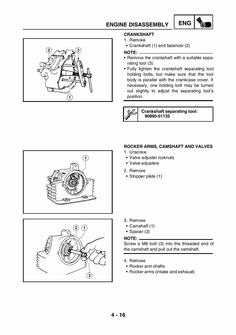
7/22/2019 Yamaha xt 125 service manual
http://slidepdf.com/reader/full/yamaha-xt-125-service-manual 99/279
4 - 16
ENGENGINE DISASSEMBLY
CRANKSHAFT
1. Remove
• Crankshaft (1) and balancer (2)
NOTE:
• Remove the crankshaft with a suitable sepa-rating tool (3).
• Fully tighten the crankshaft separating tool
holding bolts, but make sure that the tool
body is parallel with the crankcase cover. If
necessary, one holding bolt may be turned
out slightly to adjust the separating tool’s
position.
Crankshaft separating tool:
90890-01135
ROCKER ARMS, CAMSHAFT AND VALVES
1. Unscrew
• Valve adjuster locknuts
• Valve adjusters
2. Remove
• Stopper plate (1)
3. Remove
• Camshaft (1)
• Spacer (2)
NOTE:
Screw a M8 bolt (3) into the threaded end of
the camshaft and pull out the camshaft.
4. Remove
• Rocker arm shafts
• Rocker arms (intake and exhaust)

7/22/2019 Yamaha xt 125 service manual
http://slidepdf.com/reader/full/yamaha-xt-125-service-manual 100/279
4 - 17
ENGENGINE DISASSEMBLY
NOTE:
Use a slide hammer (1) to remove the rocker
arm shafts.
NOTE:
Before the valves, valve springs, valve seats,
etc. are removed from the cylinder head, the
valve sealing should be checked.
5. Check
• Valve sealing
Leakage from the valve seats → Inspect the
valve face, valve seat and seat width. See
“VALVE SPRINGS AND VALVES” page 4-
22
*****************************************************
Checking steps
• Pour fuel (1) into the intake chamber and
then into the exhaust chamber.
• Check the sealing of both valves.• Make sure there is no leakage from the valve
seats (2).
6. Remove
• Valve cotters (1)
NOTE:
Attach a compressor to compress the valve
spring with an adapter (2) between the top
retainer and the cylinder head to remove the
valve cotters.
Slide hammer:(Bolt)
90890-01085(Weight)
90890-01084
Valve spring compressor:90890-04019

7/22/2019 Yamaha xt 125 service manual
http://slidepdf.com/reader/full/yamaha-xt-125-service-manual 101/279
4 - 18
ENGENGINE DISASSEMBLY
7. Remove
• Valve retainer (1)
• Spring (2)
• Valve (3)
• Valve stem seal (4)• Valve spring seat (5)
NOTE:
Identify the position of each part very carefully
so that it can be reinstalled in its original place.

7/22/2019 Yamaha xt 125 service manual
http://slidepdf.com/reader/full/yamaha-xt-125-service-manual 102/279
4 - 19
ENGINSPECTION AND REPAIR
INSPECTION AND REPAIRCYLINDER HEAD
1. Eliminate
• Carbon deposits (from the combustion
chamber)Use a rounded scraper.
NOTE:
Do not use a sharp instrument to avoid damag-
ing or scratching
• Spark plug threads
• Valve seats
2. Inspect
• Cylinder head
• Scratches and damage → Replace
3. Measure
• Warpage
Out of specification → Resurface
*****************************************************
Warpage measurement and resurfacing
steps
• Place a straightedge (1) and a feeler gauge
(2) across the cylinder head, as shown in the
figure.
• Measure the warpage
• If the warpage is out of specification, resur-
face the cylinder head.
• Place an abrasive paper (400 ~ 600) on a flat
surface, and resurface the cylinder head
using a figure-eight sanding pattern.
NOTE:
Rotate the cylinder head several times for an
even resurfacement.
*****************************************************
Cylinder head warpage:less than 0.03 mm
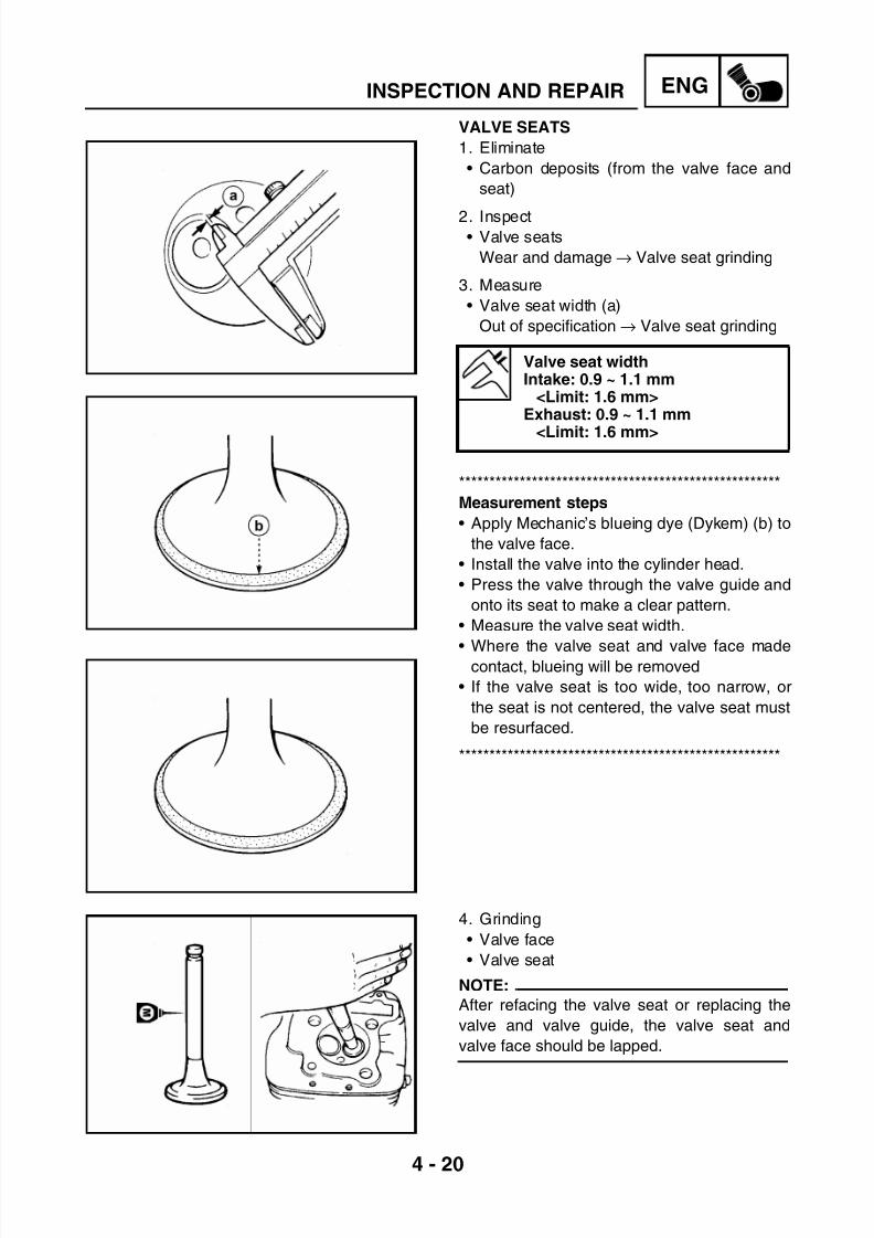
7/22/2019 Yamaha xt 125 service manual
http://slidepdf.com/reader/full/yamaha-xt-125-service-manual 103/279
4 - 20
ENGINSPECTION AND REPAIR
VALVE SEATS
1. Eliminate
• Carbon deposits (from the valve face and
seat)
2. Inspect• Valve seats
Wear and damage → Valve seat grinding
3. Measure
• Valve seat width (a)
Out of specification → Valve seat grinding
*****************************************************
Measurement steps
• Apply Mechanic’s blueing dye (Dykem) (b) to
the valve face.
• Install the valve into the cylinder head.
• Press the valve through the valve guide and
onto its seat to make a clear pattern.
• Measure the valve seat width.
• Where the valve seat and valve face madecontact, blueing will be removed
• If the valve seat is too wide, too narrow, or
the seat is not centered, the valve seat must
be resurfaced.
*****************************************************
4. Grinding
• Valve face
• Valve seat
NOTE:
After refacing the valve seat or replacing the
valve and valve guide, the valve seat and
valve face should be lapped.
Valve seat widthIntake: 0.9 ~ 1.1 mm
<Limit: 1.6 mm>Exhaust: 0.9 ~ 1.1 mm
<Limit: 1.6 mm>

7/22/2019 Yamaha xt 125 service manual
http://slidepdf.com/reader/full/yamaha-xt-125-service-manual 104/279
4 - 21
ENGINSPECTION AND REPAIR
*****************************************************
Valve lapping steps
• Apply a coarse lapping compound onto the
valve sealing surface.
CAUTION:Do not let compound enter the gap
between the valve stem and the guide.
• Apply molybdenum disulfide oil to the valve
stem.
• Install the valve into the cylinder head.
• Turn the valve until the valve face and valve
seat are evenly polished, then clean off all
compound.
NOTE:For best valve lapping results, lightly tap the
valve seat while rotating the valve back and
forth between your hand.
• Apply a fine lapping compound to the valve
face and repeat the above steps.
NOTE: \
Make sure to clean off all compound from the
valve face and valve seat after every lapping
operation.
• Apply Mechanic’s blueing dye (Dykem) (b) to
the valve face.
• Install the valve into the cylinder head.
• Press the valve onto the seat until it fits
perfectly.
• Measure the valve seat width (c) again. If the
valve seat width is out of specification, reface
and lap the valve seat.
*****************************************************

7/22/2019 Yamaha xt 125 service manual
http://slidepdf.com/reader/full/yamaha-xt-125-service-manual 105/279
4 - 22
ENGINSPECTION AND REPAIR
VALVE SPRINGS AND VALVES
1. Measure
• Valve spring free length (a).
Out of specification → Replace
2. Measure
• Spring tilt (a)Out of specification → Replace
3. Measure
• Spring contact area
Wear and damage → Replace
4. Measure
• Valve guide inside diameter
Out of specification → Replace
Valve spring free length:38.78 mm
<Minimum value: 37.0 mm>
Maximum spring tilt:1.7 mm
Valve guide inside diameterIntake: 5.000 ~ 5.012 mm
<Maximum value: 5.042 mm>Exhaust: 5.000 ~ 5.012 mm
<Maximum value: 5.042 mm>
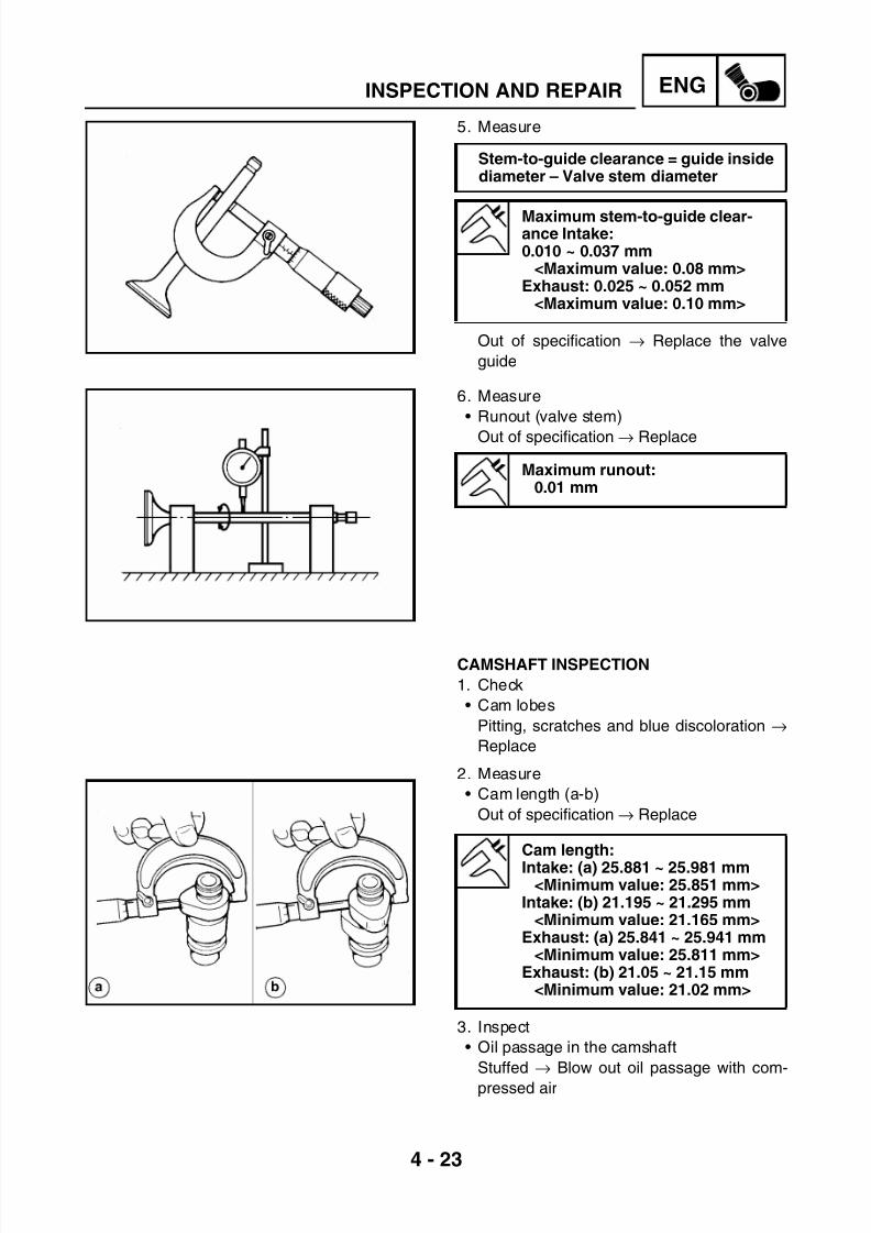
7/22/2019 Yamaha xt 125 service manual
http://slidepdf.com/reader/full/yamaha-xt-125-service-manual 106/279
4 - 23
ENGINSPECTION AND REPAIR
5. Measure
Out of specification → Replace the valve
guide
6. Measure
• Runout (valve stem)
Out of specification → Replace
CAMSHAFT INSPECTION
1. Check
• Cam lobes
Pitting, scratches and blue discoloration →
Replace
2. Measure
• Cam length (a-b)
Out of specification → Replace
3. Inspect
• Oil passage in the camshaft
Stuffed → Blow out oil passage with com-
pressed air
Stem-to-guide clearance = guide insidediameter – Valve stem diameter
Maximum stem-to-guide clear-ance Intake:0.010 ~ 0.037 mm
<Maximum value: 0.08 mm>Exhaust: 0.025 ~ 0.052 mm
<Maximum value: 0.10 mm>
Maximum runout:0.01 mm
Cam length:
Intake: (a) 25.881 ~ 25.981 mm<Minimum value: 25.851 mm>
Intake: (b) 21.195 ~ 21.295 mm<Minimum value: 21.165 mm>
Exhaust: (a) 25.841 ~ 25.941 mm<Minimum value: 25.811 mm>
Exhaust: (b) 21.05 ~ 21.15 mm<Minimum value: 21.02 mm>

7/22/2019 Yamaha xt 125 service manual
http://slidepdf.com/reader/full/yamaha-xt-125-service-manual 107/279
4 - 24
ENGINSPECTION AND REPAIR
ROCKER ARMS AND ROCKER ARM
SHAFTS INSPECTION
1. Inspect
• Cam contact surface (1)
• Adjuster surface (2)Wear, grooves, scratches and blue discol-
oration → Replace
*****************************************************
Inspection steps
• Inspect the two contact areas on the rocker
arms for signs of unusual wear.
• Rocker arm shaft hole.
• Cam contact surface.
• Excessive wear→ Replace
• Inspect the surface condition of the rocker
arm shafts.• Grooves and scratches → Replace or check
the lubrication system.
• Measure the inside diameter (a) of the rocker
arm holes.
• Out of specification → Replace
• Measure the outside diameter (b) of the
rocker arm holes.
Out of specification → Replace
*****************************************************
Inside diameter 10.000 ~10.015 mm of the rocker arm hole
<Maximum value: 10.03 mm>
Outside diameter 9.981 ~9.991 mm of the rocker arm shaft
<Minimum value: 9.95 mm>
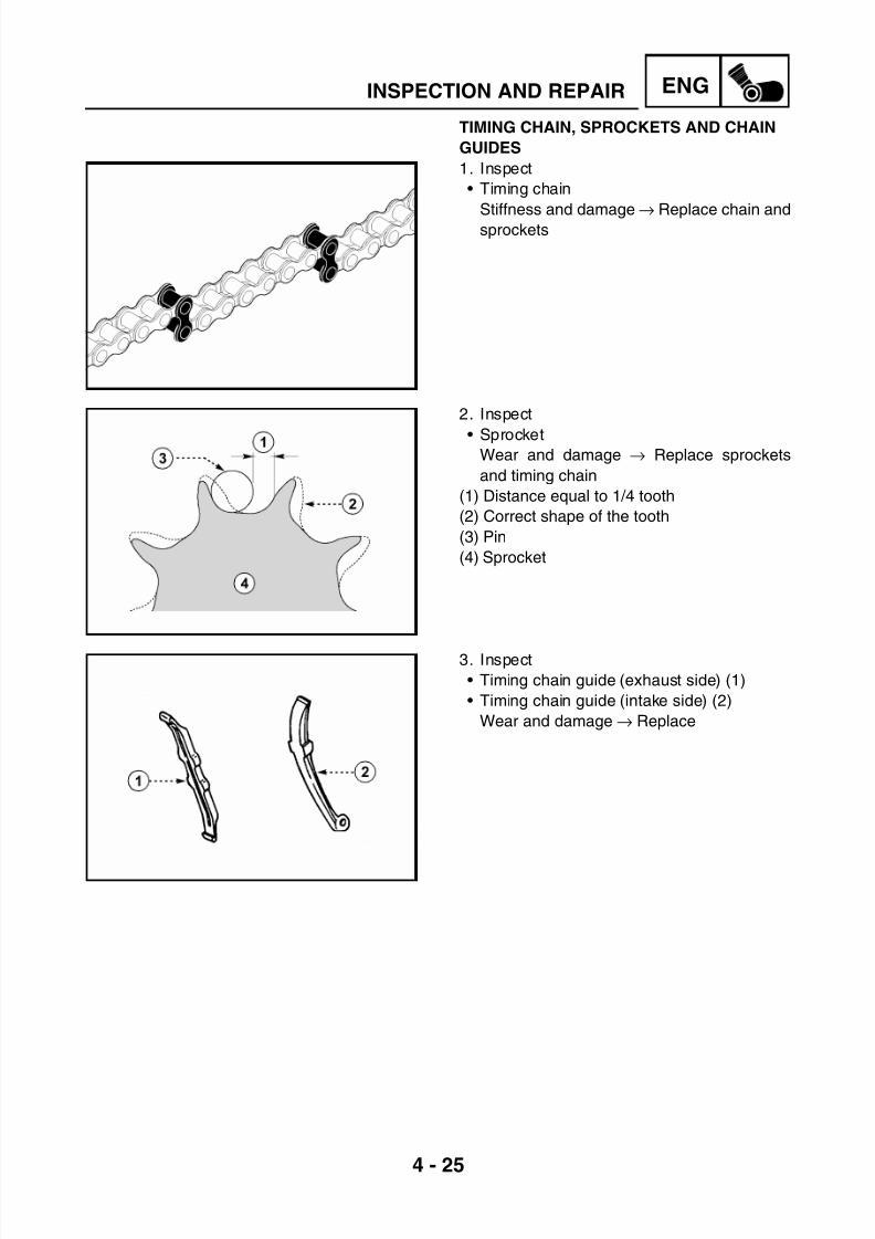
7/22/2019 Yamaha xt 125 service manual
http://slidepdf.com/reader/full/yamaha-xt-125-service-manual 108/279
4 - 25
ENGINSPECTION AND REPAIR
TIMING CHAIN, SPROCKETS AND CHAIN
GUIDES
1. Inspect
• Timing chain
Stiffness and damage→
Replace chain andsprockets
2. Inspect
• SprocketWear and damage → Replace sprockets
and timing chain
(1) Distance equal to 1/4 tooth
(2) Correct shape of the tooth
(3) Pin
(4) Sprocket
3. Inspect
• Timing chain guide (exhaust side) (1)
• Timing chain guide (intake side) (2)
Wear and damage → Replace
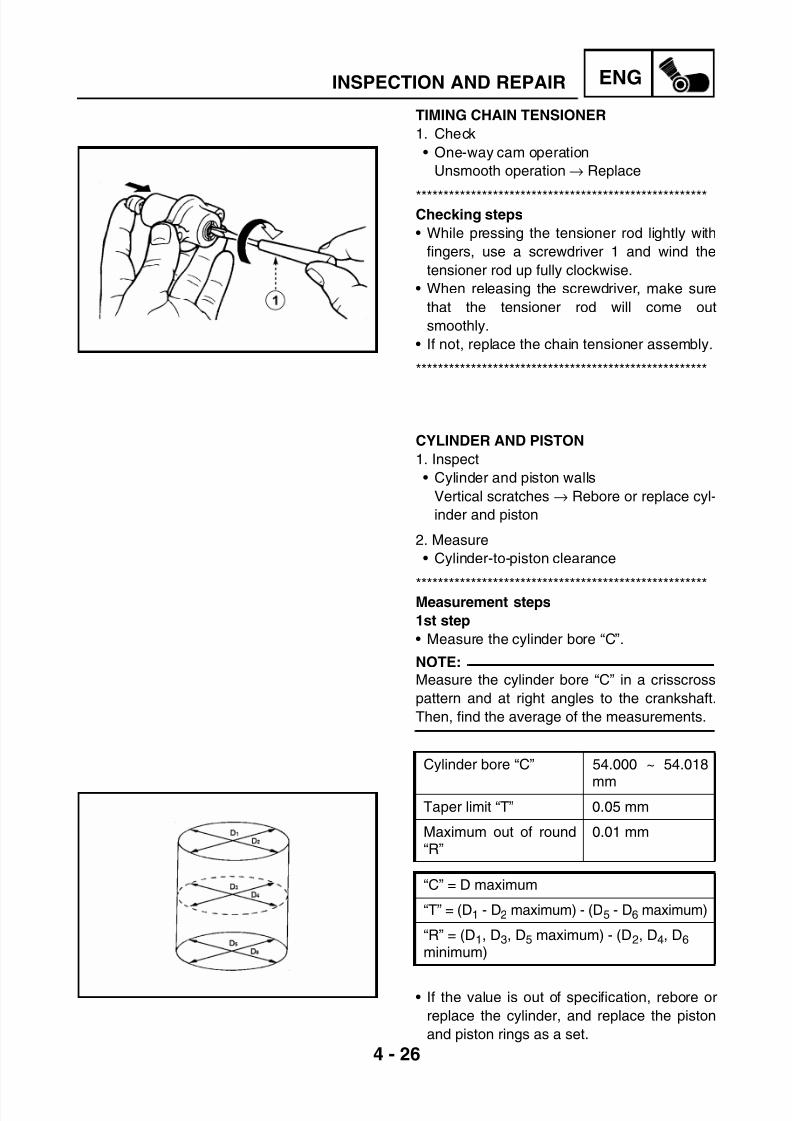
7/22/2019 Yamaha xt 125 service manual
http://slidepdf.com/reader/full/yamaha-xt-125-service-manual 109/279
4 - 26
ENGINSPECTION AND REPAIR
TIMING CHAIN TENSIONER
1. Check
• One-way cam operation
Unsmooth operation → Replace
*****************************************************Checking steps
• While pressing the tensioner rod lightly with
fingers, use a screwdriver 1 and wind the
tensioner rod up fully clockwise.
• When releasing the screwdriver, make sure
that the tensioner rod will come out
smoothly.
• If not, replace the chain tensioner assembly.
*****************************************************
CYLINDER AND PISTON
1. Inspect
• Cylinder and piston walls
Vertical scratches → Rebore or replace cyl-
inder and piston
2. Measure
• Cylinder-to-piston clearance
*****************************************************Measurement steps
1st step
• Measure the cylinder bore “C”.
NOTE:
Measure the cylinder bore “C” in a crisscross
pattern and at right angles to the crankshaft.
Then, find the average of the measurements.
• If the value is out of specification, rebore or
replace the cylinder, and replace the piston
and piston rings as a set.
Cylinder bore “C” 54.000 ~ 54.018
mmTaper limit “T” 0.05 mm
Maximum out of round“R”
0.01 mm
“C” = D maximum
“T” = (D1 - D2 maximum) - (D5 - D6 maximum)
“R” = (D1, D3, D5 maximum) - (D2, D4, D6 minimum)
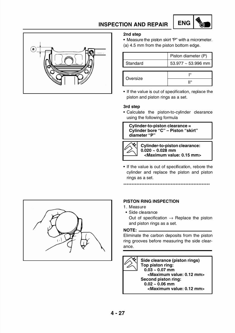
7/22/2019 Yamaha xt 125 service manual
http://slidepdf.com/reader/full/yamaha-xt-125-service-manual 110/279
4 - 27
ENGINSPECTION AND REPAIR
2nd step
• Measure the piston skirt “P” with a micrometer.
(a) 4.5 mm from the piston bottom edge.
• If the value is out of specification, replace the
piston and piston rings as a set.
3rd step
• Calculate the piston-to-cylinder clearance
using the following formula
• If the value is out of specification, rebore the
cylinder and replace the piston and piston
rings as a set.
*****************************************************
Piston diameter (P)
Standard 53.977 ~ 53.996 mm
OversizeI°
II°
Cylinder-to-piston clearance =Cylinder bore “C” – Piston “skirt”diameter “P”
Cylinder-to-piston clearance:0.020 ~ 0.028 mm
<Maximum value: 0.15 mm>
PISTON RING INSPECTION
1. Measure
• Side clearance
Out of specification → Replace the piston
and piston rings as a set.
NOTE:
Eliminate the carbon deposits from the piston
ring grooves before measuring the side clear-
ance.
Side clearance (piston rings)Top piston ring:
0.03 ~ 0.07 mm<Maximum value: 0.12 mm>
Second piston ring:0.02 ~ 0.06 mm
<Maximum value: 0.12 mm>

7/22/2019 Yamaha xt 125 service manual
http://slidepdf.com/reader/full/yamaha-xt-125-service-manual 111/279
4 - 28
ENGINSPECTION AND REPAIR
2. Position
• Piston rings into the cylinder
NOTE:
Push the ring with the piston crown so that the
ring will be parallel to the cylinder edge.
(a) 5 mm
3. Measure
• End gap
Out of specification → Replace
NOTE:
You cannot measure the end gap on the
expander spacer of the oil ring.
If the oil ring shows excessive gap, replace all
three rings.
End gap top piston ring:0.15 ~ 0.30 mm
<Maximum value: 0.40 mm>Second piston ring:
0.15 ~ 0.30 mm<Maximum value: 0.40 mm>Oil ring: 0.2 ~ 0.7 mm
PISTON PIN INSPECTION
1. Inspect
• Piston pin
Blue discoloration and grooves → Replace
and then check the lubrication system
2. Measure
• piston-to-piston pin clearance
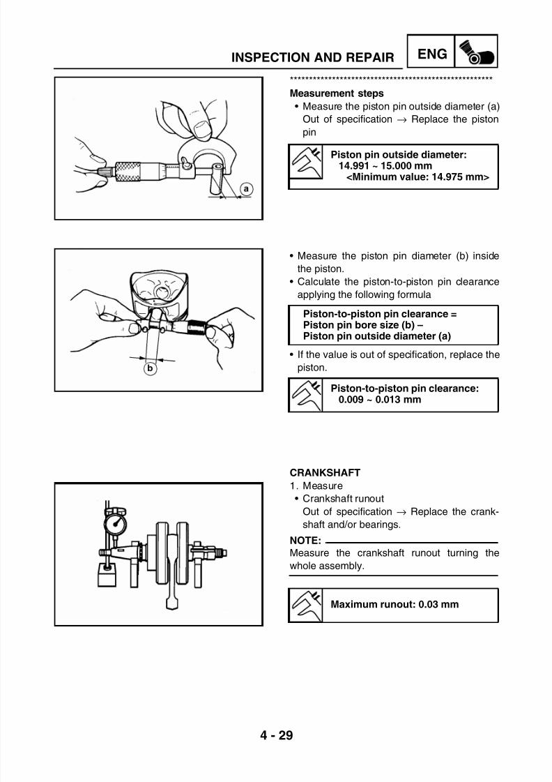
7/22/2019 Yamaha xt 125 service manual
http://slidepdf.com/reader/full/yamaha-xt-125-service-manual 112/279
4 - 29
ENGINSPECTION AND REPAIR
*****************************************************
Measurement steps
• Measure the piston pin outside diameter (a)
Out of specification → Replace the piston
pin
• Measure the piston pin diameter (b) inside
the piston.• Calculate the piston-to-piston pin clearance
applying the following formula
• If the value is out of specification, replace the
piston.
Piston pin outside diameter:14.991 ~ 15.000 mm
<Minimum value: 14.975 mm>
Piston-to-piston pin clearance =Piston pin bore size (b) –Piston pin outside diameter (a)
Piston-to-piston pin clearance:0.009 ~ 0.013 mm
CRANKSHAFT
1. Measure
• Crankshaft runout
Out of specification → Replace the crank-
shaft and/or bearings.
NOTE:
Measure the crankshaft runout turning the
whole assembly.
Maximum runout: 0.03 mm

7/22/2019 Yamaha xt 125 service manual
http://slidepdf.com/reader/full/yamaha-xt-125-service-manual 113/279
4 - 30
ENGINSPECTION AND REPAIR
2. Measure
• Connecting rod side clearance
Out of specification → Replace big end
bearing, crank pin and/or connecting rod.
3. Measure
• Crankshaft width
Out of specification → Replace crankshaft
4. Inspect
• Crankshaft sprocket (1)Wear and damage → Replace crankshaft
• Bearing (2)
Wear and damage → Replace bearing
5. Inspect
• Oil passage in crankshaft
Stuffed → Blow out oil passage with com-
pressed air
Connecting rod side clearance:0.15 ~ 0.45 mm
<Maximum value: 0.8 mm>
Crankshaft width:46.95 ~ 47.00 mm

7/22/2019 Yamaha xt 125 service manual
http://slidepdf.com/reader/full/yamaha-xt-125-service-manual 114/279

7/22/2019 Yamaha xt 125 service manual
http://slidepdf.com/reader/full/yamaha-xt-125-service-manual 115/279
4 - 32
ENGINSPECTION AND REPAIR
3. Inspect
• Clutch plates
Damage → Replace the friction plate
assembly
4. Measure• Clutch plate warpage
Out of specification → Replace the plate
assembly
Use a flat surface and a feeler gauge for the
measurement
5. Inspect
• Clutch springs
Damage → Replace the spring assembly
6. Measure
• Spring free length (a)
Out of specification → Replace the spring
assembly
7. Inspect
• Clutch housing teeth (1)Burrs, wear and damage → Eliminate the
projections or replace the clutch housing
• Clutch hub grooves (2)
Projections, wear and damage → Replace
the clutch hub
NOTE:
Projections on the clutch housing teeth and
clutch hub grooves will cause erratic operation.
8. Inspect• Primary drive gear (a)
Excessive clearance, projections, wear and
damage → Replace the clutch housing Cir-
cumferential play (if present) → Replace the
clutch housing
Clutch plate maximum warpage:less than 0.05 mm
Spring free length: 31.0 mm<Minimum value: 29.0 mm>

7/22/2019 Yamaha xt 125 service manual
http://slidepdf.com/reader/full/yamaha-xt-125-service-manual 116/279

7/22/2019 Yamaha xt 125 service manual
http://slidepdf.com/reader/full/yamaha-xt-125-service-manual 117/279
4 - 34
ENGINSPECTION AND REPAIR
4. Check
• Shift fork movement (on the fork guide bar)
Unsmooth operation → Replace the shift
fork and the guide bar.
NOTE:When the shift fork and transmission gear are
damaged, replace all the facing gears.
5. Measure
• Axle runout (main and drive)
Use a centering device and a dial gauge (1)
Out of specification → Replace the bent
axle
6. Inspect
• Gear teethBlue discoloration, grooves and wear →
Replace
• Dogs
Rounded edges, cracks and missing por-
tions → Replace
7. Inspect
• Shift shaft (1)
Damage, bends and wear → Replace
• Return spring (shift shaft) (2)
• Return spring (stopper lever) (3)
Wear and damage → Replace

7/22/2019 Yamaha xt 125 service manual
http://slidepdf.com/reader/full/yamaha-xt-125-service-manual 118/279
4 - 35
ENGINSPECTION AND REPAIR
KICK STARTER INSPECTION
1. Inspect
• Gear teeth (starter gear) (1)
• Gear teeth (sliding gear) (2)
Wear and damage→
Replace
2. Measure
• Kick clip friction force (return spring)
Out of specification → ReplaceUse a spring gauge (1)
Kick clip friction force:0.8 ~ 1.2 Kgf
OIL PUMP INSPECTION
1. Measure
• Tip clearance (A) between inner rotor (1)
and outer rotor (2)
• Side clearance (B) between outer rotor and
pump housing (3)
Out of specification → Replace the oil pump
assembly• Clearance between housing and rotor (C)
between pump housing (3) and rotors (1-2) Out of
specification→ Replace the oil pump assembly
Tip clearance:(A) 0.15 mm
<Maximum value: 0.20 mm>Side clearance:
(B) 0.06 ~ 0.10 mm<Maximum value: 0.15 mm>
Clearance between housing and
rotor:(C) 0.06 ~ 0.10 mm
<Maximum value: 0.15 mm>

7/22/2019 Yamaha xt 125 service manual
http://slidepdf.com/reader/full/yamaha-xt-125-service-manual 119/279
4 - 36
ENGINSPECTION AND REPAIR
2. Inspect
• Rotary filter
Cracks and damage → Replace
Dirt → Clean
3. Inspect
• Oil suction screenCracks and damage → Replace
Dirt → Clean
OIL PASSAGE INSPECTION (RIGHT
CRANKCASE HALF COVER)
1. Inspect
• Oil passage
Blockage → Blow out oil passage with com-
pressed air
ENGINE COVER
1. Thoroughly wash the crankcase halves with
kerosene.
2. Thoroughly clean all the gasket mating sur-
faces and crankcase mating surfaces.
3. Inspect
• Crankcase halves
Cracks and damage → Replace
• Oil passage
Blockage → Blow out oil passage with com-
pressed air

7/22/2019 Yamaha xt 125 service manual
http://slidepdf.com/reader/full/yamaha-xt-125-service-manual 120/279
4 - 37
ENGINSPECTION AND REPAIR
BEARINGS AND OIL SEALS
1. Inspect
• Bearings
Clean and lubricate, then turn the inner seal
using a finger.Roughness → Replace
2. Inspect
• Oil seals
Wear and damage → Replace
CIRCLIPS AND WASHERS
1. Inspect
• Circlips
• Washers
Damage, loosening and bends → Replace

7/22/2019 Yamaha xt 125 service manual
http://slidepdf.com/reader/full/yamaha-xt-125-service-manual 121/279
4 - 38
ENGENGINE ASSEMBLY AND ADJUSTMENTS
ENGINE ASSEMBLY AND ADJUSTMENTSVALVES, ROCKER ARMS AND CAMSHAFT
(1) Valve cotter(2) Valve retainer
(3) Spring(4) Valve stem seal(5) Valve spring seat(6) Valve (intake)(7) Valve (exhaust)(8) Locknut(9) Adjuster
(10) Rocker arm(11) Rocker arm shaft (intake)
(12) Rocker arm shaft (exhaust)(13) Circlip(14) Valve guide(15) Camshaft(16) Plate
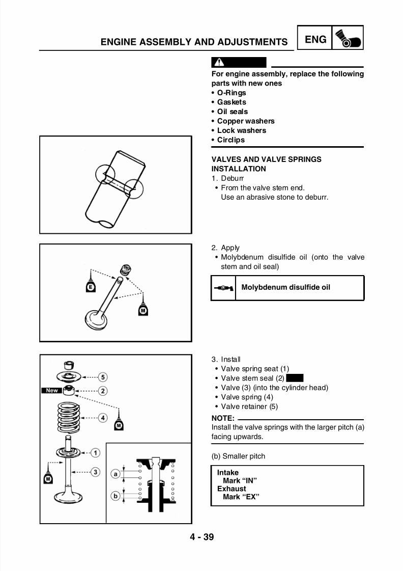
7/22/2019 Yamaha xt 125 service manual
http://slidepdf.com/reader/full/yamaha-xt-125-service-manual 122/279
4 - 39
ENGENGINE ASSEMBLY AND ADJUSTMENTS
WARNING
For engine assembly, replace the following
parts with new ones
• O-Rings
• Gaskets• Oil seals
• Copper washers
• Lock washers
• Circlips
VALVES AND VALVE SPRINGS
INSTALLATION
1. Deburr
• From the valve stem end.
Use an abrasive stone to deburr.
2. Apply
• Molybdenum disulfide oil (onto the valve
stem and oil seal)
3. Install
• Valve spring seat (1)
• Valve stem seal (2)
• Valve (3) (into the cylinder head)
• Valve spring (4)• Valve retainer (5)
NOTE:
Install the valve springs with the larger pitch (a)
facing upwards.
(b) Smaller pitch
MMM Molybdenum disulfide oil
IntakeMark “IN”
Exhaust
Mark “EX”
New

7/22/2019 Yamaha xt 125 service manual
http://slidepdf.com/reader/full/yamaha-xt-125-service-manual 123/279

7/22/2019 Yamaha xt 125 service manual
http://slidepdf.com/reader/full/yamaha-xt-125-service-manual 124/279

7/22/2019 Yamaha xt 125 service manual
http://slidepdf.com/reader/full/yamaha-xt-125-service-manual 125/279
4 - 42
ENGENGINE ASSEMBLY AND ADJUSTMENTS
CRANKSHAFT AND BALANCER SHAFT
(1) Crank pin(2) Axle shaft (flywheel side)(3) Connecting rod(4) Big end bearing
(5) Crankshaft bearing(6) Key(7) Balancer shaft(8) Bearing

7/22/2019 Yamaha xt 125 service manual
http://slidepdf.com/reader/full/yamaha-xt-125-service-manual 126/279
4 - 43
ENGENGINE ASSEMBLY AND ADJUSTMENTS
1. Install
• Crankshaft separating tool
2. Install
• Crankshaft
NOTE:
Hold the connecting rod at Top Dead Center
with one hand while turning the nut of the
installing tool with the other. Operate the
installing tool until the crankshaft bottoms
against the bearing.
Crankshaft separating tool:Rod: 90890-01274
Bolt: 90890-01275Adapter: 90890-01278Spacer: 90890-04881
CAUTION:
To avoid scratching the crankshaft and to
ease the installation procedure, apply
grease onto the oil seal lips and apply
engine oil onto each bearing.
3. Install
• Balancer shaftAlways use a new O-Ring.
NOTE:
When installing the balancer shaft, align the
mark (a) on the crankshaft drive gear with the
mark (b) on the balancer gear.
4. Install
• Neutral switch

7/22/2019 Yamaha xt 125 service manual
http://slidepdf.com/reader/full/yamaha-xt-125-service-manual 127/279
4 - 44
ENGENGINE ASSEMBLY AND ADJUSTMENTS
TRANSMISSION
(1) Pinion(2) Valve stem seal(3) Bearing(4) 5th wheel gear
(5) Drive axle(6) 2nd wheel gear(7) 3rd wheel gear(8) 4th wheel gear(9) 1st wheel gear(10) Bearing(11) Bearing
(12) 5th pinion gear(13) 2nd pinion gear(14) 3rd pinion gear(15) 4th pinion gear
(16) Main axle(17) Plate(18) Bearing

7/22/2019 Yamaha xt 125 service manual
http://slidepdf.com/reader/full/yamaha-xt-125-service-manual 128/279
4 - 45
ENGENGINE ASSEMBLY AND ADJUSTMENTS
SHIFTER
(1) Shift fork guide bar (long)(2) Shift fork 3(3) Shift fork 1(4) Shifter
(5) Segment(6) Shift fork guide bar (short)(7) Shift fork 2

7/22/2019 Yamaha xt 125 service manual
http://slidepdf.com/reader/full/yamaha-xt-125-service-manual 129/279
4 - 46
ENGENGINE ASSEMBLY AND ADJUSTMENTS
TRANSMISSION, SHIFT FORK AND
SHIFTER INSTALLATION
1. Measure
• Main axle length (a).
2. Install
• Push rod n. 2 (1) to main axle hole.
3. Install
• Push lever (1)
• Spring, circlip, oil seal (2)
4. Install
• O-Ring (2) to the groove of the drive axle
pinion holding plate.
5. Install
• Left lower shift fork (1)
• Left upper shift fork (2)
• Right center shift fork (3)
• Shift fork guide bar (short) (4)
• Shift fork guide bar (long) (5)
NOTE:
Install the shift forks with the embossed mark
in sequence L, R, C beginning from the right.
Length (main axle):82.25 ~ 83.45 mm

7/22/2019 Yamaha xt 125 service manual
http://slidepdf.com/reader/full/yamaha-xt-125-service-manual 130/279
4 - 47
ENGENGINE ASSEMBLY AND ADJUSTMENTS
6. Check
• Shifter operation
Unsmooth operation → Adjust
NOTE:
Check the transmission and shift forks forsmooth operation by turning the shifter with
your hand.
Tightening sequence
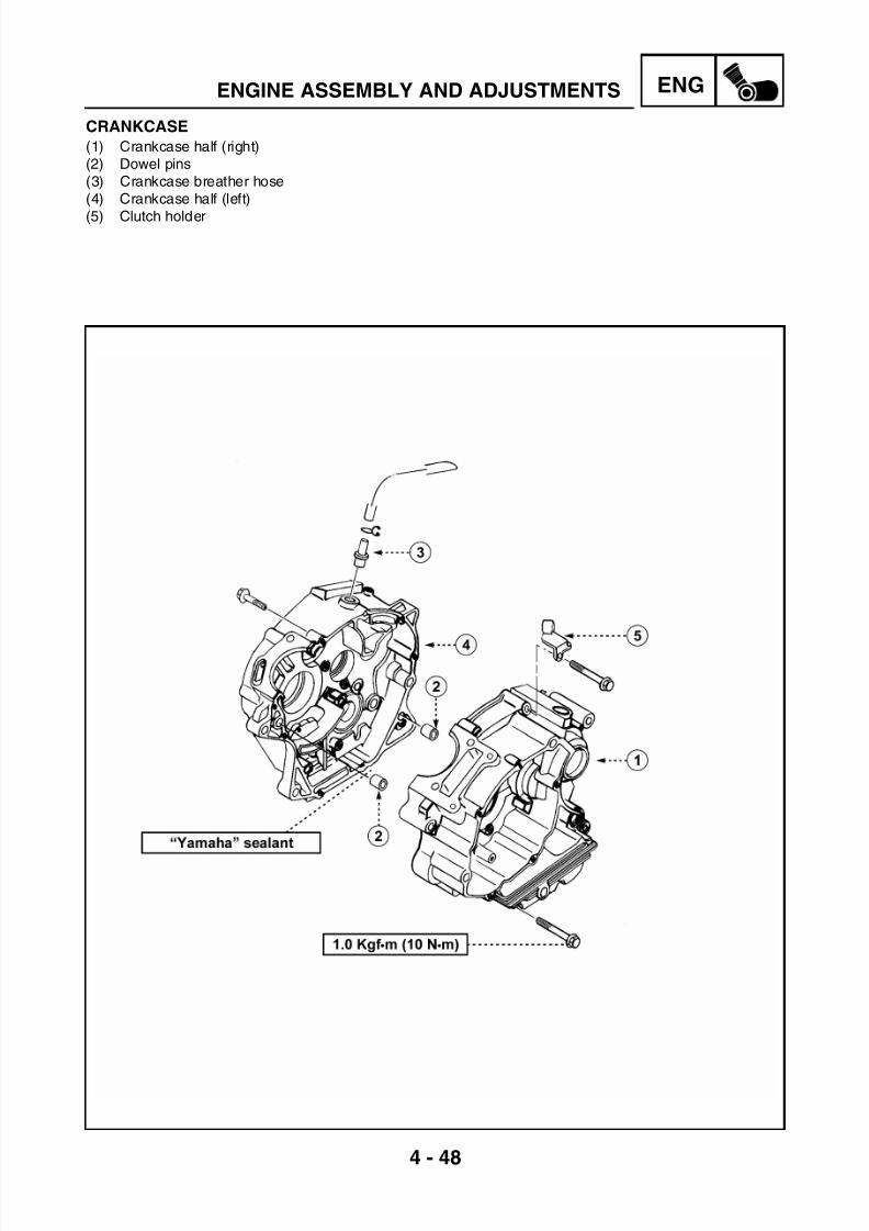
7/22/2019 Yamaha xt 125 service manual
http://slidepdf.com/reader/full/yamaha-xt-125-service-manual 131/279
4 - 48
ENGENGINE ASSEMBLY AND ADJUSTMENTS
CRANKCASE
(1) Crankcase half (right)(2) Dowel pins(3) Crankcase breather hose(4) Crankcase half (left)
(5) Clutch holder

7/22/2019 Yamaha xt 125 service manual
http://slidepdf.com/reader/full/yamaha-xt-125-service-manual 132/279
4 - 49
ENGENGINE ASSEMBLY AND ADJUSTMENTS
CRANKCASE (LEFT)
1. Apply
• Sealant (onto the crankcase mating
surfaces)
NOTE:
Do not allow any sealant to come in contact with
the oil galleries (a-b) as shown in the figure.
2. Install
• Dowel pins (1)
3. Install
• Crankcase half (left) (onto the rightcrankcase)
NOTE:
Tap lightly on the crankcase with a soft hammer.
4. Tighten
• Crankcase bolts
NOTE:Tighten the bolts in a decreasing order (see
the numbers in the figure).
5. Apply
• Engine oil 4T in the crank pin, bearings and
oil delivery holes
6. Check
• Crankshaft and transmission operation
Unsmooth operation → repair
“Yamaha” sealant:90890-01215
T R .
.
T R .
.
T R .
.
Crankcase bolts:1.0 Kgf·m (10 N·m)

7/22/2019 Yamaha xt 125 service manual
http://slidepdf.com/reader/full/yamaha-xt-125-service-manual 133/279

7/22/2019 Yamaha xt 125 service manual
http://slidepdf.com/reader/full/yamaha-xt-125-service-manual 134/279
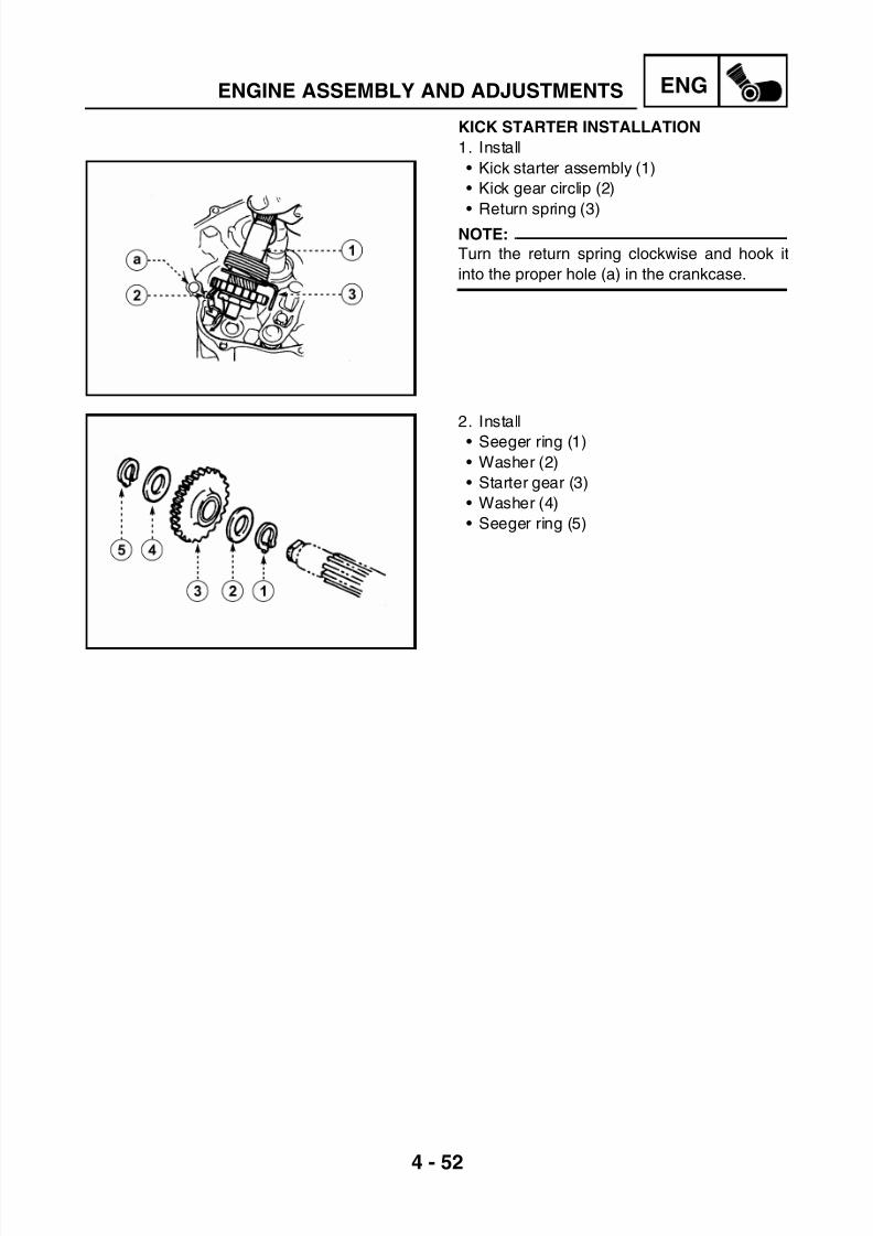
7/22/2019 Yamaha xt 125 service manual
http://slidepdf.com/reader/full/yamaha-xt-125-service-manual 135/279
4 - 52
ENGENGINE ASSEMBLY AND ADJUSTMENTS
KICK STARTER INSTALLATION
1. Install
• Kick starter assembly (1)
• Kick gear circlip (2)
• Return spring (3)NOTE:
Turn the return spring clockwise and hook it
into the proper hole (a) in the crankcase.
2. Install
• Seeger ring (1)
• Washer (2)
• Starter gear (3)
• Washer (4)
• Seeger ring (5)

7/22/2019 Yamaha xt 125 service manual
http://slidepdf.com/reader/full/yamaha-xt-125-service-manual 136/279
4 - 53
ENGENGINE ASSEMBLY AND ADJUSTMENTS
CLUTCH, CLUTCH HOUSING AND OIL PUMP
(1) Clutch spring(2) Clutch pressure plate(3) Push plate(4) Push rod (1)
(5) Friction plate(6) Clutch plate(7) Clutch boss(8) Spacer(9) Clutch housing(10) Ball(11) Push rod (2)(12) Push lever
(13) Primary drive gear(14) Rotary filter(15) Key(16) Oil pump drive gear
(17) Washer(18) Oil pump driven gear(19) Oil pump(20) Gasket

7/22/2019 Yamaha xt 125 service manual
http://slidepdf.com/reader/full/yamaha-xt-125-service-manual 137/279
4 - 54
ENGENGINE ASSEMBLY AND ADJUSTMENTS
OIL PUMP INSTALLATION
1. Lubricate
• Oil delivery passage (right crankcase)
• Oil pump assembly
2. Install • Washer (1)
• Oil pump drive gear (2)
• Key
• Rotary filter
NOTE:
• Install the washer (1) with mark “H” facing out.
• Install the oil pump drive gear with its groovefacing in.
• Install the rotary filter with its more projecting
side facing in and place the key into the
groove of the crankshaft.
CLUTCH GEAR INSTALLATION
1. Install
• Primary drive gear (1)
• Clutch housing (2)
• Washer (3)
• Primary gear nut (4)
NOTE:
Install the primary drive gear with the stamp
facing out. Place a folded aluminium or copper
plate (a) between the teeth of the primary drive
gear (1) and the teeth of the clutch housinggear (2).
Recommended lubricant:Engine oil

7/22/2019 Yamaha xt 125 service manual
http://slidepdf.com/reader/full/yamaha-xt-125-service-manual 138/279
4 - 55
ENGENGINE ASSEMBLY AND ADJUSTMENTS
CLUTCH INSTALLATION
1. Install
• Washer (1)
• Spacer (2)
• Clutch housing (3)• Spacer (4)
• Clutch boss (5)
• Lock washer (6)
• Clutch boss nut (7)
2. Tighten
• Clutch boss nut (2)
NOTE:Tighten the clutch boss nut (2) while holding
the clutch boss with a universal clutch holder
(3)
3. Bend
• Lock washer edge (1) (along a flat side of
the nut)
4. Install
• Friction plate (1)
• Clutch plate (2)
NOTE:
• Install the clutch plates and friction plates
alternately on the clutch boss, starting with a
clutch plate and ending with a clutch plate.• Coat all clutch and friction plates with engine
oil before installation.
• Be sure to install a clutch plate with projec-
tion offset approximately 90° from previous
plates projection. Continue this procedure in
a clockwise direction until all clutch plates
are installed.
Universal clutch holder:90890-04086
T R .
.
T R .
.
T R .
.
Clutch boss nut:6.0 Kgf•m (60 N•m)

7/22/2019 Yamaha xt 125 service manual
http://slidepdf.com/reader/full/yamaha-xt-125-service-manual 139/279
4 - 56
ENGENGINE ASSEMBLY AND ADJUSTMENTS
5. Install
• Ball
6. Install
• Push rod n.1 (1)
• Push plate (2)
• Washer (3)
• Push rod nut n.1 (4)
7. Install
• Pressure plate (1)• Clutch springs (2)
• Bolts (3)
NOTE:
Tighten the clutch spring bolts gradually, using
a crisscross pattern.
8. Check• Push lever position
Push the push lever assembly in the arrow
direction and make sure that the marks are
aligned.
(a) Mark on the push lever assembly
(b) Mark on the crankcase
T R .
.
T R .
.
T R .
.
Bolts (clutch springs):0.6 Kgf•m (6 N•m)

7/22/2019 Yamaha xt 125 service manual
http://slidepdf.com/reader/full/yamaha-xt-125-service-manual 140/279
4 - 57
ENGENGINE ASSEMBLY AND ADJUSTMENTS
9. Adjust • Push lever position
*****************************************************
Adjustment steps
• Loosen the locknut (1)• Turn the adjuster (2) clockwise or counter-
clockwise to align marks.
• Hold the adjuster to prevent it from moving
and tighten the locknut to specification.
CAUTION:
Take care not to overtighten the adjuster 2
and remove the freeplay between both
push rods.
• Tighten lock nut (1).
*****************************************************
10. Install
• Dowel pins
• Crankcase gasket
• Crankcase cover (right)
NOTE:
Tighten the bolts in a decreasing order (see
the numbers in the figure).
11. Install
• Kick starter
T R .
.
T R .
.
T R .
.
Lock nut:0.8 Kgf•m (8 N•m)
T R .
.
T R .
.
T R .
.
Crankcase cover bolts:1.0 Kgf•m (10 N•m)
T
R .
.
T
R .
.
T
R .
.
Kick starter nut:5.0 Kgf•m (50 N•m)

7/22/2019 Yamaha xt 125 service manual
http://slidepdf.com/reader/full/yamaha-xt-125-service-manual 141/279
4 - 58
ENG
2
12
1,0 Kgf.m (10 N.m)
131210
11
1
7,0 Kgf.m (70 N.m)
6
0,7 Kgf.m (7 N.m) 97
54
3
8
New
ENGINE ASSEMBLY AND ADJUSTMENTS
CDI MAGNETO
(1) Timing chain(2) Timing chain guide (intake side)(3) Dowel pins(4) Starter gear (1)
(5) Plate(6) Washer(7) Starter gear (2)(8) Key(9) CDI magneto
(10) Stator(11) Gasket(12) Dowel pins(13) Crankcase cover

7/22/2019 Yamaha xt 125 service manual
http://slidepdf.com/reader/full/yamaha-xt-125-service-manual 142/279
4 - 59
ENGENGINE ASSEMBLY AND ADJUSTMENTS
STARTER GEAR INSPECTION
1. Inspect
• Starter gear teeth (a-b-c)
Burrs, chips, roughness and wear →
Replace2. Check
• Free-wheel gear operation.
Push the guide bars in the arrow direction.
Unsmooth operation → Replace
*****************************************************
Checking steps
• Hold the free-wheel gear.
• When turning the (big) starter gear clockwise
(A), the free-wheel gear and the starter gear
should be engaged.
• If not, the free-wheel gear is faulty.• Replace
• When turning the starter gear counterclock-
wise (B), it should turn freely.
• If not, the free-wheel gear is faulty.
• Replace
*****************************************************
CDI MAGNETO AND STARTER GEAR
1. Install
• Timing chain
• Chain guide
NOTE:
Fasten a safety wire to the timing chain to
prevent it from falling into the crankcase.
T R .
.
T R .
.
T R .
.
Bolt (chain guide):
1.0 Kgf•m (10 N•m)

7/22/2019 Yamaha xt 125 service manual
http://slidepdf.com/reader/full/yamaha-xt-125-service-manual 143/279
4 - 60
ENGENGINE ASSEMBLY AND ADJUSTMENTS
2. Install
• Starter gear (1)
• Plate (2)
3. Apply
• Engine oil 4T (in the starter gears)
4. Install
• Washer (1)
• Starter gear (2)
5. Install
• Key
• CDI magneto
NOTE:
Temporarily install the flywheel aligning the
groove with the key. Turn the starter gear
clockwise and install the flywheel into the starter
gear.
6. Tighten• Nut (CDI magneto)
NOTE:
Tighten the flywheel (2) with the rotor holder
(3) while tightening the nut (1). Do not allow
the rotor holder to touch the projections on the
rotor.
7. Install
• Guide bars
• Crankcase cover gasket
• Crankcase cover (left)
8. Connect• Neutral switch lead.
T R .
.
T R .
.
T R .
.
Plate bolt:
0.7 Kgf•m (7 N•m)
T R .
.
T R .
.
T R .
.
CDI magneto nut:7.0 Kgf•m (70 N•m)
Rotor holder:90890-01701
T R .
.
T R .
.
T R .
.
Crankcase cover bolts:1.0 Kgf•m (10 N•m)
New

7/22/2019 Yamaha xt 125 service manual
http://slidepdf.com/reader/full/yamaha-xt-125-service-manual 144/279
4 - 61
ENGENGINE ASSEMBLY AND ADJUSTMENTS
CYLINDER AND PISTON
(1) Cylinder(2) O-Ring(3) Cylinder gasket(4) Dowel pins
(5) Piston rings(6) Piston pin circlip(7) Piston(8) Piston pin

7/22/2019 Yamaha xt 125 service manual
http://slidepdf.com/reader/full/yamaha-xt-125-service-manual 145/279
4 - 62
ENGENGINE ASSEMBLY AND ADJUSTMENTS
CYLINDER HEAD
(1) Bolt(2) Washer(3) Bolt(4) Valve cover (intake)
(5) O-Ring(6) Valve cover (exhaust)(7) Cylinder head
(8) Dowel pins(9) Cylinder head gasket(10) O-Ring(11) Cylinder head side cover(12) Spark plug
Crankcase sealant:90890-01215

7/22/2019 Yamaha xt 125 service manual
http://slidepdf.com/reader/full/yamaha-xt-125-service-manual 146/279
4 - 63
ENGENGINE ASSEMBLY AND ADJUSTMENTS
DRIVE GEAR AND TIMING CHAIN
(1) Gasket(2) Timing chain tensioner assembly(3) Timing chian guide (intake side)(4) Drive gear
(5) Timing chain(6) Timing chain guide (exhaust side)

7/22/2019 Yamaha xt 125 service manual
http://slidepdf.com/reader/full/yamaha-xt-125-service-manual 147/279
4 - 64
ENGENGINE ASSEMBLY AND ADJUSTMENTS
PISTON RINGS, PISTON AND CYLINDER
INSTALLATION
1. Install in the following order
• Expander spacer (oil ring) (1)
• Side rails (oil ring) (2)• Second ring (3)
• Top ring (4)
NOTE:
• Make sure to install the piston rings so that
the manufacturer’s mark or number is facing
up.
• Lubricate the piston and piston rings properly
with engine oil.
2. Install
• Piston (1)
• Piston pin (2)
• Pin circlip (3)
NOTE:
• Apply engine oil onto the piston pins.• The mark (a) on the piston must face the
exhaust side of the cylinder.
• Before installing the piston pin circlip, cover
the crankcase opening with a clean rag.
3. Install
• Dowel pins (1)
• Cylinder gasket (2)
New
New

7/22/2019 Yamaha xt 125 service manual
http://slidepdf.com/reader/full/yamaha-xt-125-service-manual 148/279
4 - 65
ENGENGINE ASSEMBLY AND ADJUSTMENTS
4. Install
• Piston rings (1)
NOTE:
Place the piston ring ends as shown in the fig-
ure.
(a) Top ring end
(b) Oil ring end (lower)
(c) Oil ring end (upper)
(d) 2nd ring end
5. Lubricate
• Piston outer surface
• Piston rings
• Cylinder inner surface
6. Install
• O-Ring
• Cylinder (1)
NOTE:
• Install the cylinder with one hand while com-
pressing the piston rings with the other hand.• Pass the timing chain guide (exhaust side)
through the timing chain cavity.
CYLINDER HEAD INSTALLATION
1. Install• Dowel pins (1)
• Cylinder head gasket (2)
• Timing chain guide (exhaust side) (3)
New
New
New

7/22/2019 Yamaha xt 125 service manual
http://slidepdf.com/reader/full/yamaha-xt-125-service-manual 149/279
4 - 66
ENGENGINE ASSEMBLY AND ADJUSTMENTS
2. Install
• Cylinder head
• Bolt with washer (cylinder head)
NOTE:
• Apply engine oil onto the bolt thread.
• Tighten the bolts starting with the lower num-
bered one.
3. Install
• Drive gear
• Timing chain
*****************************************************
Installation steps
• Turn the crankshaft counter-clockwise until
the mark (a) matches the stationary pointer
(b).
• Align the mark (c) on the drive gear with the
stationary pointer (d) on the cylinder head.
• Fit the timing chain (1) onto drive gear (2)
and then install the drive gear on the cam-shaft.
NOTE:
When installing the drive gear, keep the timing
chain as tense as possible on the exhaust
side.
CAUTION:
Do not turn the crankshaft during installa-
tion of the camshaft. Damage or improper
valve timing will result.
• Remove the safety wire from the timing
chain.
*****************************************************
T R .
.
T R .
.
T R .
.
Bolts (cylinder head):
M8 (1-4):2.2 Kgf•m (22 N•m)
M6 (5-6):1.0 Kgf•m (10 N•m)

7/22/2019 Yamaha xt 125 service manual
http://slidepdf.com/reader/full/yamaha-xt-125-service-manual 150/279
4 - 67
ENGENGINE ASSEMBLY AND ADJUSTMENTS
4. Install
• Plate
5. Install
• Bolt (sprocket)
NOTE:
Hold the CDI magneto nut with a wrench and
mount the bolt.
6. Check
• CDI magneto mark (a)
Align the stationary pointer (b) with the
crankcase cover (left).• drive gear mark (d)
Align the stationary pointer (c) with the cyl-
inder head.
Out of alignment → Align
7. Install
• Timing chain tensioner
*****************************************************
Installation steps
• Remove the tensioner cover bolt.• While pressing the tensioner rod lightly with
fingers, use a screwdriver (1) and wind the
tensioner rod up fully clockwise.
• While pressing the tensioner rod lightly,
install the gasket (4), the chain tensioner (5),and tighten the bolts (6) to the specified
torque.
• Release the screwdriver.
• Install the gasket (2) and tighten the cover
bolt
(1) to the specified torque.
*****************************************************
T R .
.
T R .
.
T R .
.
Bolt (timing chain sprocket):2.0 Kgf•m (20 N•m)
T R .
.
T R .
.
T R .
.
Bolts (timing chain tensioner):1.0 Kgf•m (10 N•m)
Cover bolt (timing chain ten-sioner):
0.75 Kgf•m (7.5 N•m)
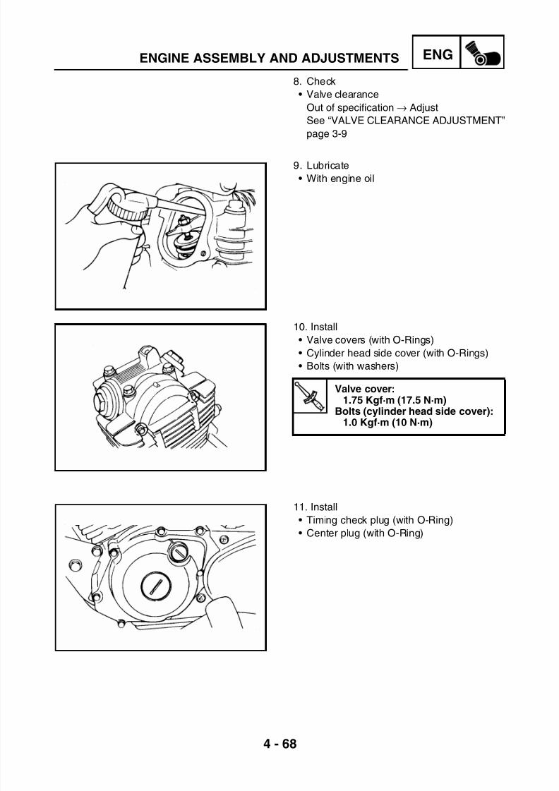
7/22/2019 Yamaha xt 125 service manual
http://slidepdf.com/reader/full/yamaha-xt-125-service-manual 151/279
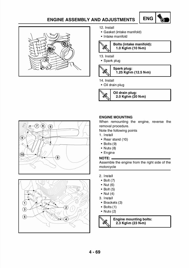
7/22/2019 Yamaha xt 125 service manual
http://slidepdf.com/reader/full/yamaha-xt-125-service-manual 152/279
4 - 69
ENGENGINE ASSEMBLY AND ADJUSTMENTS
12. Install
• Gasket (intake manifold)
• Intake manifold
13. Install
• Spark plug
14. Install
• Oil drain plug
T R .
.
T R .
.
T R .
.
Bolts (intake manifold):1.0 Kgf•m (10 N•m)
T R .
.
T R .
.
T R .
.
Spark plug:1.25 Kgf•m (12.5 N•m)
T R .
.
T R .
.
T R .
.
Oil drain plug:2.0 Kgf•m (20 N•m)
ENGINE MOUNTING
When remounting the engine, reverse the
removal procedure.
Note the following points
1. Install
• Rear stand (10)• Bolts (9)
• Nuts (8)
• Engine
NOTE:
Assemble the engine from the right side of the
motorcycle
2. Install
• Bolt (7)
• Nut (6)
• Bolt (5)
• Nut (4)
3. Install
• Brackets (3)
• Bolts (1)
• Nuts (2)
T R .
.
T R .
.
T R .
.
Engine mounting bolts:2.3 Kgf•m (23 N•m)

7/22/2019 Yamaha xt 125 service manual
http://slidepdf.com/reader/full/yamaha-xt-125-service-manual 153/279
4 - 70
ENGENGINE ASSEMBLY AND ADJUSTMENTS
4. Connect • 4-pin connector (1)
• 2-pin connector (2)
• Spark plug pipette (3)
• Starter motor connector (4)
5. Install• Sump cover
See “ENGINE SUMP GUARD INSTALLA-
TION” page 3-6
6. Install
• Shift pedal (1)
7. Install
• MufflerSee “EXHAUST SYSTEM INSPECTION”
page 3-21
8. Install
• Transmission chain
See “CHAIN INSTALLATION” page 6-34
9. Install
• Clutch cable
T R .
.
T R .
.
T R .
.
Shift pedal bolt:0.3 Kgf•m (3 N•m)

7/22/2019 Yamaha xt 125 service manual
http://slidepdf.com/reader/full/yamaha-xt-125-service-manual 154/279
4 - 71
ENGENGINE ASSEMBLY AND ADJUSTMENTS
10. Adjust
• Clutch cable clearance (A)
See “CLUTCH ADJUSTMENT” page 3-22
11. Install
• CarburetorSee “INSTALLATION” page 5-8
12. Install
• Battery
CAUTION:
Connect the positive lead (2) first and then
connect the negative lead (1).
13. Fill
• Engine oil
See “ENGINE OIL CHANGE” page 3-18
14. Install
• Fuel tank
See “FUEL TANK INSTALLATION” page 3-
3• Seat
See “SIDE COVER INSTALLATION” page
3-6
15. Adjust
• Engine idling speed
See “CO MEASUREMENT AND IDLING
SPEED ADJUSTMENT” page 3-11
• Accelerator cable clearance
See “THROTTLE CABLE ADJUSTMENT”
page 3-13

7/22/2019 Yamaha xt 125 service manual
http://slidepdf.com/reader/full/yamaha-xt-125-service-manual 155/279
CARB
CHAPTER 5
CARBURETOR
CARBURETOR................................................................................................5-1COMPONENT DESCRIPTION..................................................................5-1REMOVAL................................................................................................. 5-2DISASSEMBLY .........................................................................................5-3CHECKS AND CONTROLS ...................................................................... 5-4ASSEMBLY ...............................................................................................5-6INSTALLATION.........................................................................................5-8FUEL LEVEL ADJUSTMENT.................................................................... 5-9

7/22/2019 Yamaha xt 125 service manual
http://slidepdf.com/reader/full/yamaha-xt-125-service-manual 156/279
5 - 1
CARB
CARBURETORCARBURETORCOMPONENT DESCRIPTION(1) Throttle cable unit(2) Throttle valve unit
(3) Throttle valve spring(4) Float chamber drain screw(5) Carburetor float chamber(6) Float chamber gasket(7) Carburetor body(8) Float pin(9) Float(10) Float needle valve assembly(11) Main jet
(12) Main nozzle(13) O-ring
(14) Setter needle jet(15) Pilot screw(16) Pilot jet(17) Heater(18) Starter unit(19) Throttle stop screw
CARBURETOR

7/22/2019 Yamaha xt 125 service manual
http://slidepdf.com/reader/full/yamaha-xt-125-service-manual 157/279
5 - 2
CARBCARBURETOR
REMOVAL
WARNING
Securely support the motorcycle so there
is no danger of it falling over.
1. Stand the motorcycle on a level surface.
2. Remove
• Seat
See “SEAT REMOVAL” page 3-2
• Fuel tank
See “FUEL TANK REMOVAL” page 3-3
3. Remove
• Fuel (carburetor float chamber)
NOTE:
Position a cloth under the drain pipe for theabsorption of the fuel poured out.
WARNING
Gasoline is highly flammable; avoid fuel
leakages on the warm engine.
4. Disconnect
• Breather hose (1)
• Fuel hose (2)
• Fuel hose (3)• Carburetor heater leads (4)
5. Unscrew • Intake manifold clamp screw (5)
• Filter case sleeve clamp screw (6)
6. Remove
• Filter case sleeve (7)
• Carburetor (8)
• Throttle cable (9)
• Starter cable (10)
• Cover (11)
• Throttle valve (12)

7/22/2019 Yamaha xt 125 service manual
http://slidepdf.com/reader/full/yamaha-xt-125-service-manual 158/279
5 - 3
CARBCARBURETOR
DISASSEMBLY
1. Remove
• Carburetor float chamber (1)
• Float chamber gasket
2. Remove• Float pin (1)
• Float (2)
• Needle valve (3)
3. Remove
• Plate (1)
• Needle valve holder (2)
• Main jet (3)
• Spray nozzle (4)
• Pilot jet (5)
• Pilot adjust screw (6)

7/22/2019 Yamaha xt 125 service manual
http://slidepdf.com/reader/full/yamaha-xt-125-service-manual 159/279
5 - 4
CARBCARBURETOR
CHECKS AND CONTROLS
1. Inspect
• Carburetor body
• Carburetor float chamber
• Nozzle housingCracks and damage → Replace
• Carburetor float chamber body
Dirt → Clean
• Fuel circuit
Dirt → Clean as indicated below
*****************************************************
Cleaning phases
• Wash the carburetor with kerosene or petrol.
Do not clean the carburetor with caustic solu-
tions.
• Blow compressed air into passages and noz-zles
*****************************************************
2. Inspect
• Float
Damage → Replace
3. Inspect• Needle valve (1)
• Needle valve holder (2)
• O-Ring (3)
Dirt → Clean
Wear and damage → Replace

7/22/2019 Yamaha xt 125 service manual
http://slidepdf.com/reader/full/yamaha-xt-125-service-manual 160/279
5 - 5
CARBCARBURETOR
4. Inspect
• Jet needle (1)
• Spray nozzle (2)
• Main jet (3)
• Pilot screw (4)• Pilot jet (5)
Wear and damage → Replace
Dirt → Blow compressed air into the noz-
zles
5. Check
• Correct slidingPut the throttle valve into the carburetor
body and make sure that it slides freely
Dirt → Replace

7/22/2019 Yamaha xt 125 service manual
http://slidepdf.com/reader/full/yamaha-xt-125-service-manual 161/279
5 - 6
CARBCARBURETOR
ASSEMBLY
CAUTION:
Before assembly wash all components with
kerosene
1. Install
• Pilot jet (1)
• Pilot screw (2)
2. Install
• O-Ring gasket (new)
• Spray (1)
• Main jet (2)
3. Install
• Needle valve holder (1)
• Plate
• Needle valve (2)

7/22/2019 Yamaha xt 125 service manual
http://slidepdf.com/reader/full/yamaha-xt-125-service-manual 162/279
5 - 7
CARBCARBURETOR
4. Install
• Float (1)
• Float pin (2)
5. Measure • Float height (A) without gasket
If the float height is incorrect → Adjust
6. Install
• Carburetor float chamber gasket (1) (new)• Carburetor float chamber (2)
Float height:18.9 mm

7/22/2019 Yamaha xt 125 service manual
http://slidepdf.com/reader/full/yamaha-xt-125-service-manual 163/279

7/22/2019 Yamaha xt 125 service manual
http://slidepdf.com/reader/full/yamaha-xt-125-service-manual 164/279
5 - 9
CARBCARBURETOR
FUEL LEVEL ADJUSTMENT
1. Measure
• Fuel level (A)
Out of specification → Adjust
*****************************************************
Adjustment steps
• Place the motorcycle on a level surface
• Place a lifting device or support under the
engine so that the carburetor is in a vertical
position
• Connect fuel level gauge (1) to drain pipe (2)
• Unscrew drain screw (3)
• Keep the gauge in a vertical position next to
the carburetor float chamber line
• Measure fuel level (A) by means of the gauge
• Incorrect fuel level→ Adjust
• Remove the carburetor
• Check the needle valve and its housing
• Replace them if they are worn out
• Otherwise adjust the level by slightly bending
the float tab (4) slightly
• Install the carburetor
• Check again the fuel level
*****************************************************
Fuel level below the float chamberline: 7.5 mm
Fuel level gauge:90890-01312

7/22/2019 Yamaha xt 125 service manual
http://slidepdf.com/reader/full/yamaha-xt-125-service-manual 165/279
CHAS
CHAPTER 6
CHASSIS
FRONT WHEEL...............................................................................................6-1COMPONENT DESCRIPTION..................................................................6-1REMOVAL................................................................................................. 6-2CHECKS AND CONTROLS ...................................................................... 6-2INSTALLATION.........................................................................................6-4
FRONT BRAKE ...............................................................................................6-5COMPONENT DESCRIPTION (XT 125 R) ...............................................6-5COMPONENT DESCRIPTION (XT 125 X) ...............................................6-6BRAKE PAD REPLACEMENT (XT 125 R) ...............................................6-7BRAKE PAD REPLACEMENT (XT 125 X)................................................6-8
BRAKE CALIPER DISASSEMBLY (XT 125 R) ......................................... 6-9BRAKE CALIPER DISASSEMBLY (XT 125 X) ....................................... 6-10MASTER CYLINDER DISASSEMBLY.................................................... 6-11INSPECTION AND REPAIR....................................................................6-12ASSEMBLY OF BRAKE CALIPER (XT 125 R) ....................................... 6-14
ASSEMBLY OF BRAKE CALIPER (XT 125 X) ....................................... 6-15MASTER CYLINDER ASSEMBLY..........................................................6-17
REAR WHEEL ...............................................................................................6-18COMPONENT DESCRIPTION................................................................6-18REMOVAL............................................................................................... 6-19CHECKS AND CONTROLS .................................................................... 6-20INSTALLATION.......................................................................................6-22
REAR BRAKE ...............................................................................................6-23COMPONENT DESCRIPTION................................................................6-23BRAKE PAD REPLACEMENT................................................................ 6-24BRAKE CALIPER DISASSEMBLY..........................................................6-25MASTER CYLINDER DISASSEMBLY.................................................... 6-26INSPECTION AND REPAIR....................................................................6-26ASSEMBLY OF BRAKE CALIPER..........................................................6-28
MASTER CYLINDER ASSEMBLY..........................................................6-30
DRIVE CHAIN AND SPROCKETS................................................................6-31COMPONENT DESCRIPTION................................................................6-31CHAIN REMOVAL...................................................................................6-32CHECKS AND CONTROLS .................................................................... 6-32CHAIN INSTALLATION...........................................................................6-34
FRONT SUSPENSION ..................................................................................6-36COMPONENT DESCRIPTION................................................................6-36REMOVAL OF RH/LH FORK LEG .......................................................... 6-37
FORK LEG DISASSEMBLY.................................................................... 6-37CHECKS AND CONTROLS .................................................................... 6-40

7/22/2019 Yamaha xt 125 service manual
http://slidepdf.com/reader/full/yamaha-xt-125-service-manual 166/279
CHAS
FORK LEG ASSEMBLY.......................................................................... 6-41RH/LH FORK LEG INSTALLATION........................................................ 6-44
STEERING HEAD AND HANDLEBAR .........................................................6-45
COMPONENT DESCRIPTION................................................................6-45STEERING HEAR REMOVAL.................................................................6-46HANDLEBAR REMOVAL........................................................................ 6-47HANDLEBAR INSPECTION....................................................................6-48INSPECTION OF STEERING HEAD ...................................................... 6-48STEERING HEAD INSTALLATION.........................................................6-49HANDLEBAR INSTALLATION ................................................................ 6-50
REAR SUSPENSION ....................................................................................6-52COMPONENT DESCRIPTION................................................................6-52RECOMMENDATIONS FOR USE .......................................................... 6-53
DISPOSAL INSTRUCTIONS...................................................................6-53SHOCK ABSORBER REMOVAL ............................................................ 6-54SWINGARM REMOVAL..........................................................................6-55CHECKS AND CONTROLS .................................................................... 6-56SHOCK ABSORBER INSTALLATION ....................................................6-57SWINGARM INSTALLATION..................................................................6-58

7/22/2019 Yamaha xt 125 service manual
http://slidepdf.com/reader/full/yamaha-xt-125-service-manual 167/279
6 - 1
CHAS
CHASSISFRONT WHEELCOMPONENT DESCRIPTION
(1) Bolt
(2) Wheel axle
(3) Bearing
(4) Spacer
(5) Tire
(6) Rim
(7) Hub
(8) Bearing
(9) Spacer
(10) Speedometer sensor
(11) Bolt
(12) Dust seal
Tyre inflation pres-sure
Front Rear
Up to 90 kg load1.8 bar
(26.1 psi)
1.9 bar
(27.6 psi)
With maximum load178 kg
2.0 bar(29.0 psi)
2.1 bar(30.5 psi)
ATire sizeXT 125 R: 90/90-21 54SXT 125 X: 100/80-17 52S
CRim runout limitsVertical: 1.0 mmLateral: 0.5 mm
BRim sizeXT 125 R: 1.85x21XT 125 X: 2.5x17
DTire wear limit1 mm
FRONT WHEEL

7/22/2019 Yamaha xt 125 service manual
http://slidepdf.com/reader/full/yamaha-xt-125-service-manual 168/279
6 - 2
CHASFRONT WHEEL
REMOVAL
WARNING
Securely support the motorcycle so there
is no danger of it falling over.
1. Stand the motorcycle on a level surface.
2. Elevate the rear wheel by placing a suitable
stand under the engine.
3. Remove
• Speedometer sensor (10)
• Bolt (1)
• Wheel axle (2)
• Dust seal (12)
• Spacer (9)
• Front wheel (13)NOTE:
Do not depress the brake lever when the
wheel is off the motorcycle, otherwise the
brake pads will be forced shut.
CHECKS AND CONTROLS
1. Eliminate any corrosion from the parts.
2. Check
• Wheel axle (2)
Roll the axle on a flat surface.
• Warpage→ Replace
WARNING
Do not attempt to straighten the axle.
3. Check
• Tire
Wear and damage → Replace
See “TYRE INSPECTION” page 3-31
• Front wheel
Damage and bends → Replace
See “WHEEL INSPECTION” page 3-33.

7/22/2019 Yamaha xt 125 service manual
http://slidepdf.com/reader/full/yamaha-xt-125-service-manual 169/279
6 - 3
CHASFRONT WHEEL
4. Check
• Wheel spokes
Damage and bends → Replace
Loose spoke → Retighten
Turn the wheel and tap the spokes with ascrew driver.
NOTE:
A tight spoke will emit a clear, ringing tone; a
loose spoke will sound flat.
5. Tighten
• Loose spoke
NOTE:
Check the wheel runout after tightening the
spokes.
6. Measure
• Rim runout
Out of specification → Check the rim and
the bearing play.
T R .
.
Wheel spokes:0.3 Kgf•m (3 N•m)
T R .
.
Rim runout limits:
Vertical (A): 1.0 mmLateral (B): 0.5 mm
WARNING
After mounting a tire, ride conservatively to
allow the tire do be adapted to the rim. Fail-
ure to do so may cause an accident result-
ing in motorcycle damage and possible
operator injury. After a tire repair orreplacement, be sure to torque tighten the
valve stem locknut (14) to specification.
T R .
.
Valve locknut (14):0.3 Kgf·m (3 N·m)
14

7/22/2019 Yamaha xt 125 service manual
http://slidepdf.com/reader/full/yamaha-xt-125-service-manual 170/279
6 - 4
CHASFRONT WHEEL
7. Check
• Bearing (3-8)
Abnormal noise, irregular free play and
rotation → Replace
(A) side free play(B) axial free play
*****************************************************Bearing replacement steps:
• Remove bearings (3-8) using a bearing
puller.
• Install the new bearings.
NOTE:
Use a socket wrench (15) that matches theoutside diameter of the bearing.
CAUTION:
Do not strike the centre race (16) or balls
(17) of the bearing. Contact should be
made only with the outer race (18).
*****************************************************
INSTALLATION
1. Lubricate
• Wheel axle (2)
• Dust seal (12)
• Bearing (3-8)
2. Assemble
• Dust seal (12)
• Wheel axle (13)
• Spacer (9)
• Bolt (1)
3. Tighten
• Wheel axle (2)
• Bolt (1)
4. Install
• Speedometer sensor (10)
Use lithium soap base grease
T
R .
.
Wheel axle (2):4.5 Kgf·m (45 N·m)
Bolt (1):2.0 Kgf·m (20 N·m)
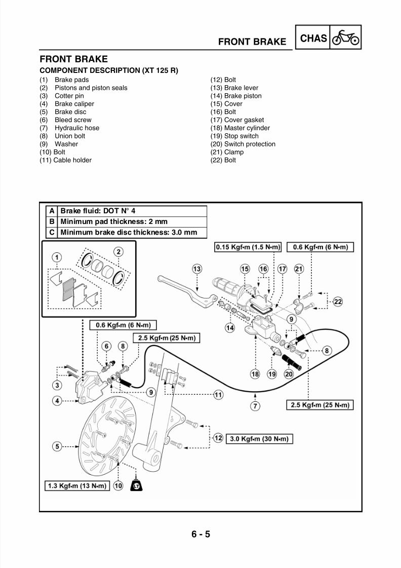
7/22/2019 Yamaha xt 125 service manual
http://slidepdf.com/reader/full/yamaha-xt-125-service-manual 171/279
6 - 5
CHASFRONT BRAKE
FRONT BRAKECOMPONENT DESCRIPTION (XT 125 R)
(1) Brake pads(2) Pistons and piston seals
(3) Cotter pin(4) Brake caliper(5) Brake disc(6) Bleed screw(7) Hydraulic hose(8) Union bolt(9) Washer(10) Bolt(11) Cable holder
(12) Bolt(13) Brake lever
(14) Brake piston(15) Cover(16) Bolt(17) Cover gasket(18) Master cylinder(19) Stop switch(20) Switch protection(21) Clamp(22) Bolt
A Brake fluid: DOT N° 4
B Minimum pad thickness: 2 mm
C Minimum brake disc thickness: 3.0 mm
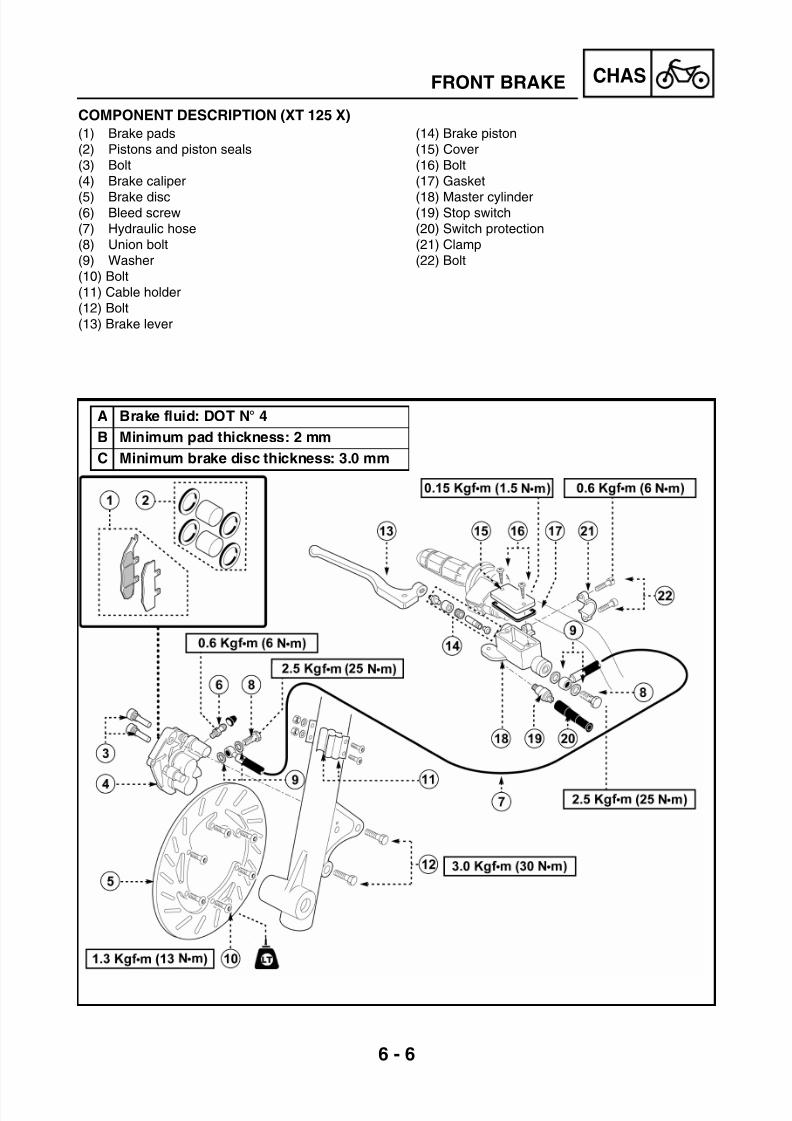
7/22/2019 Yamaha xt 125 service manual
http://slidepdf.com/reader/full/yamaha-xt-125-service-manual 172/279
6 - 6
CHASFRONT BRAKE
COMPONENT DESCRIPTION (XT 125 X)
(1) Brake pads(2) Pistons and piston seals(3) Bolt(4) Brake caliper
(5) Brake disc(6) Bleed screw(7) Hydraulic hose(8) Union bolt(9) Washer(10) Bolt(11) Cable holder(12) Bolt(13) Brake lever
(14) Brake piston(15) Cover(16) Bolt(17) Gasket
(18) Master cylinder(19) Stop switch(20) Switch protection(21) Clamp(22) Bolt
A Brake fluid: DOT N° 4
B Minimum pad thickness: 2 mm
C Minimum brake disc thickness: 3.0 mm

7/22/2019 Yamaha xt 125 service manual
http://slidepdf.com/reader/full/yamaha-xt-125-service-manual 173/279
6 - 7
CHASFRONT BRAKE
CAUTION:
Brake disc components rarely require dis-
assembly.
• Disassemble the components only if
absolutely necessary.• Do not use solvents on internal brake
components.
• Do not use contaminated brake fluid for
cleaning.
• Avoid contact with the eyes.
• Avoid contact with painted surfaces or
plastic parts.
BRAKE PAD REPLACEMENT (XT 125 R)
NOTE:
It is not necessary to disassemble the brake
caliper and the hydraulic transmission to
replace the brake pads.
WARNING
Securely support the motorcycle so there
is no danger of it falling over.
1. Remove
• Bolt (12)
• Brake caliper (4)
• Cotter pin (3)
• Brake pads (1)
NOTE:
When replacing the pads, replace also spring
retaining clips (3), if necessary.
2. Install
• Brake pads (1)
NOTE:
Be careful when mounting the vibration-proofplates; the arrow must show the running direc-
tion.
Minimum pad thickness (A):2 mm
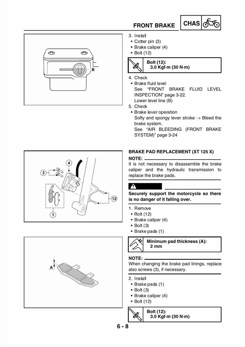
7/22/2019 Yamaha xt 125 service manual
http://slidepdf.com/reader/full/yamaha-xt-125-service-manual 174/279
6 - 8
CHASFRONT BRAKE
3. Install
• Cotter pin (3)
• Brake caliper (4)
• Bolt (12)
4. Check
• Brake fluid level
See “FRONT BRAKE FLUID LEVEL
INSPECTION” page 3-22.
Lower level line (B)
5. Check
• Brake lever operation
Softy and spongy lever stroke → Bleed the
brake system.
See “AIR BLEEDING (FRONT BRAKE
SYSTEM)” page 3-24
T R .
.
Bolt (12):3.0 Kgf·m (30 N·m)
BRAKE PAD REPLACEMENT (XT 125 X)
NOTE:
It is not necessary to disassemble the brake
caliper and the hydraulic transmission to
replace the brake pads.
WARNING
Securely support the motorcycle so there
is no danger of it falling over.
1. Remove
• Bolt (12)
• Brake caliper (4)
• Bolt (3)
• Brake pads (1)
NOTE:
When changing the brake pad linings, replace
also screws (3), if necessary.
2. Install
• Brake pads (1)
• Bolt (3)
• Brake caliper (4)
• Bolt (12)
Minimum pad thickness (A):2 mm
T R .
.
Bolt (12):3.0 Kgf·m (30 N·m)
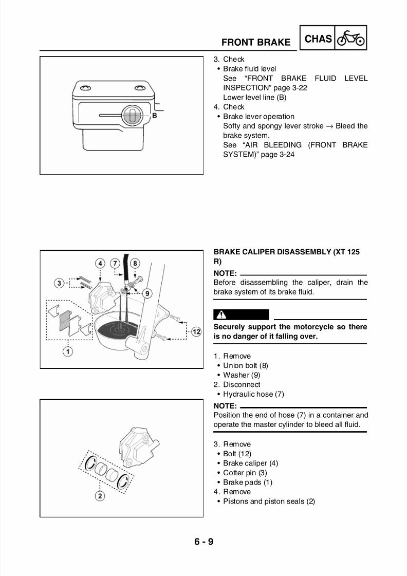
7/22/2019 Yamaha xt 125 service manual
http://slidepdf.com/reader/full/yamaha-xt-125-service-manual 175/279

7/22/2019 Yamaha xt 125 service manual
http://slidepdf.com/reader/full/yamaha-xt-125-service-manual 176/279
6 - 10
CHASFRONT BRAKE
*****************************************************
Piston and piston seal removal steps:
• Blow compressed air into the hole to push
out the pistons from the caliper.
WARNING• Do not force out the piston from the cali-
per body.
• Cover the pistons with a rag and use care
so that pistons do not cause injury as
they are expelled from the caliper.
CAUTION:
To remove the piston seals, extract them
with your hands and do not use tools.
*****************************************************
BRAKE CALIPER DISASSEMBLY (XT 125
X)
NOTE:
Before disassembling the caliper, drain the
brake system of its brake fluid.
WARNING
Securely support the motorcycle so there
is no danger of it falling over.
1. Remove
• Union bolt (8)
• Washer (9)
2. Disconnect
• Hydraulic hose (7)
NOTE:Position the end of hose (7) in a container and
operate the master cylinder to bleed all fluid.
3. Remove
• Bolt (12)
• Brake caliper (4)
• Bolt (3)
• Brake pads (1)
4. Remove
• Pistons and piston seals (2)

7/22/2019 Yamaha xt 125 service manual
http://slidepdf.com/reader/full/yamaha-xt-125-service-manual 177/279
6 - 11
CHASFRONT BRAKE
*****************************************************
Piston and piston seal removal steps:
• Blow compressed air into the hole to push
out the pistons from the caliper.
WARNING• Do not force out the piston from the cali-
per body.
• Cover the pistons with a rag and use care
so that pistons do not cause injury as
they are expelled from the caliper.
CAUTION:
To remove the piston seals, extract them
with your hands and do not use tools.
*****************************************************
MASTER CYLINDER DISASSEMBLY
NOTE:
Before disassembling the caliper, drain the
brake system of its brake fluid.
WARNING
Securely support the motorcycle so there
is no danger of it falling over.
1. Remove
• Rear-view mirror (23)
• Brake lever (13)
• Clamp (21)
2. Disconnect
• Stop switch (19)
3. Remove• Union bolt (8)
• Washer (9)
• Hydraulic hose (7)
NOTE:
Place a container under pump (18) to collect
the brake fluid.

7/22/2019 Yamaha xt 125 service manual
http://slidepdf.com/reader/full/yamaha-xt-125-service-manual 178/279
6 - 12
CHASFRONT BRAKE
INSPECTION AND REPAIR
WARNING
All internal parts should be cleaned in new
brake fluid only. Do not use solvents; they
may cause deformation.
1. Check
• Pistons and piston seals (2)
Bends and wear → Replace
• Brake caliper (4)
Damage → Replace
• Oil delivery passages
Blow out with compressed air
2. Check
• Caliper bracket (24)
Only for model XT 125 X
Damage → Replace
3. Check
• Master cylinder (18)
Wear and damage → Replace
• Oil delivery passages
Blow out with compressed air
4. Check
• Brake piston (14) and seals
Wear and damage → Replace
• Cover gasket (17)
Wear and damage → Replace
• Hydraulic hose (7)
Wear and damage → Replace
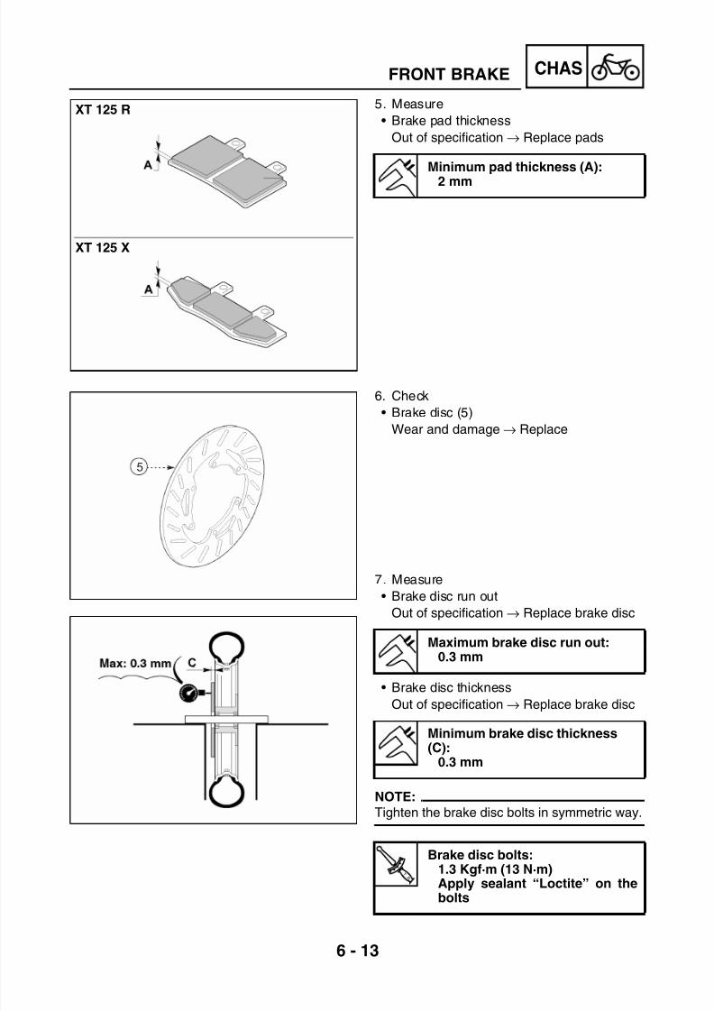
7/22/2019 Yamaha xt 125 service manual
http://slidepdf.com/reader/full/yamaha-xt-125-service-manual 179/279
6 - 13
CHASFRONT BRAKE
5. Measure
• Brake pad thickness
Out of specification → Replace pads
6. Check
• Brake disc (5)
Wear and damage → Replace
7. Measure
• Brake disc run out
Out of specification → Replace brake disc
• Brake disc thickness
Out of specification → Replace brake disc
NOTE:
Tighten the brake disc bolts in symmetric way.
Minimum pad thickness (A):2 mm
Maximum brake disc run out:0.3 mm
Minimum brake disc thickness(C):
0.3 mm
T R .
.
Brake disc bolts:1.3 Kgf·m (13 N·m)
Apply sealant “Loctite” on thebolts
XT 125 R
XT 125 X
5

7/22/2019 Yamaha xt 125 service manual
http://slidepdf.com/reader/full/yamaha-xt-125-service-manual 180/279
6 - 14
CHASFRONT BRAKE
ASSEMBLY OF BRAKE CALIPER (XT 125
R)
WARNING
All internal parts should be cleaned in new
brake fluid only.
1. Install
• Pistons and piston seals (2)
NOTE:
Always use new seals for the caliper pistons.
2. Install• Brake pads (1)
NOTE:
Be careful when mounting the vibration-proof
plates; the arrow must show the running direc-
tion.
• Cotter pin (3)
• Brake caliper (4)
• Washer (9)
• Hydraulic hose (7)• Union bolt (8)
WARNING
• Proper brake hose routing is essential to
guarantee safe motorcycle operation.
• Always use new copper washers.
3. Fill
• Brake fluid
Recommended brake liquid:DOT N° 4
T R .
.
Bolt (12):3.0 Kgf·m (30 N·m)
Bolt (8):2.5 Kgf·m (25 N·m)
Recommended brake liquid:DOT N° 4

7/22/2019 Yamaha xt 125 service manual
http://slidepdf.com/reader/full/yamaha-xt-125-service-manual 181/279
6 - 15
CHASFRONT BRAKE
CAUTION:
Brake fluid may erode painted surfaces or
plastic parts.
WARNING
• Use only the designated quality brake
fluid: otherwise, the rubber seals may
deteriorate, causing leakage and poor
brake performance.
• Refill with the same type of brake fluid;
mixing fluids may result in a harmful
chemical reaction and lead to poor perfor-
mance.
• Be careful that water does not enter the
pump when refilling. Water will signifi-
cantly lower the boiling point of the fluid
and may result in vapour lock.
4. Check
• Brake system operation
See “AIR BLEEDING (FRONT BRAKE
SYSTEM)” page 3-24
• Brake fluid level
See “FRONT BRAKE FLUID LEVEL
INSPECTION” page 3-22
ASSEMBLY OF BRAKE CALIPER (XT 125
X)
WARNING
All internal parts should be cleaned in newbrake fluid only.
1. Install
• Pistons and piston seals (2)
NOTE:
Always use new seals for the caliper pistons.
Recommended brake liquid:DOT N° 4

7/22/2019 Yamaha xt 125 service manual
http://slidepdf.com/reader/full/yamaha-xt-125-service-manual 182/279
6 - 16
CHASFRONT BRAKE
2. Install
• Brake pads (1)
• Bolt (3)
• Brake caliper (4)
• Washer (9)• Hydraulic hose (7)
• Union bolt (8)
WARNING
• Proper brake hose routing is essential to
guarantee safe motorcycle operation.• Always use new copper washers.
3. Fill
• Brake fluid
CAUTION:
Brake fluid may erode painted surfaces or
plastic parts.
WARNING
• Use only the designated quality brake
fluid: otherwise, the rubber seals may
deteriorate, causing leakage and poor
brake performance.
• Refill with the same type of brake fluid;
mixing fluids may result in a harmful
chemical reaction and lead to poor perfor-
mance.
• Be careful that water does not enter the
pump when refilling. Water will signifi-
cantly lower the boiling point of the fluid
and may result in vapour lock.
4. Check
• Brake system operation
See “AIR BLEEDING (FRONT BRAKE
SYSTEM)” page 3-24
• Brake fluid levelSee “FRONT BRAKE FLUID LEVEL
INSPECTION” page 3-22
T R .
.
Bolt (12):3.0 Kgf·m (30 N·m)
Bolt (8):2.5 Kgf·m (25 N·m)
Recommended brake liquid:DOT N° 4

7/22/2019 Yamaha xt 125 service manual
http://slidepdf.com/reader/full/yamaha-xt-125-service-manual 183/279
6 - 17
CHASFRONT BRAKE
MASTER CYLINDER ASSEMBLY
WARNING
All internal parts should be cleaned in new
brake fluid only.
1. Install
• Master cylinder (18)
• Clamp (21)
2. Install
• Washer (9)
• Hydraulic hose (7)
• Union bolt (8)
WARNING
• Proper brake hose routing is essential to
guarantee safe motorcycle operation.• Always use new copper washers.
3. Connect
• Stop switch (19)
4. Install
• Rear-view mirror (23)
• Brake lever (13)
5. Fill
• Brake fluid
6. Check
• Brake system operation
See “AIR BLEEDING (FRONT BRAKE
SYSTEM)” page 3-24
• Brake fluid level
See “FRONT BRAKE FLUID LEVEL
INSPECTION” page 3-22
Recommended brake liquid:DOT N° 4
T R .
.
Bolt (22):0.6 Kgf·m (6 N·m)
T R .
.
Bolt (8):2.5 Kgf·m (25 N·m)
Recommended brake liquid:DOT N° 4

7/22/2019 Yamaha xt 125 service manual
http://slidepdf.com/reader/full/yamaha-xt-125-service-manual 184/279
6 - 18
CHASREAR WHEEL
REAR WHEELCOMPONENT DESCRIPTION
(1) Nut(2) Washer
(3) Tire(4) Bearing(5) Spacer(6) Rim(7) Nut(8) Hub(9) Bearing(10) Drive chain(11) Sprocket(12) Bolt
(13) Spacer(14) Wheel axle
(15) Dust sealTyre inflation pres-sure
Front Rear
Up to 90 kg load1.8 bar
(26.1 psi)
1.9 bar
(27.6 psi)
With maximum load178 kg
2.0 bar(29.0 psi)
2.1 bar(30.5 psi)
ATire sizeXT 125 R: 120/80-18 62SXT 125 X: 130/70-17 62S
CRim runout limitsVertical: 1.0 mmLateral: 0.5 mm
BRim sizeXT 125 R: 2.50x18XT 125 X: 3.00x17
D Tire wear limit: 1 mm
E Drive chain slack

7/22/2019 Yamaha xt 125 service manual
http://slidepdf.com/reader/full/yamaha-xt-125-service-manual 185/279
6 - 19
CHASREAR WHEEL
REMOVAL
WARNING
Securely support the motorcycle so there
is no danger of it falling over.
1. Stand the motorcycle on a level surface.
2. Position a support under the engine and lift
the rear wheel.
3. Loosen
• Nut (1)
• Chain puller bolts (22)
4. Remove
• Nut (1)
• Washer (2)
• Wheel axle (14)• Spacer (13)
• Dust seal (15)
NOTE:
After removing wheel axle (14), take case not
to lose collar (13).
5. Remove
• Rear wheel (16)
NOTE:
Before removing the wheel, push it forward, to
remove the drive chain (10) from driven
sprocket (11).
WARNING
Do not depress the brake lever when the
wheel is off the motorcycle, otherwise the
brake pads will be forced shut.
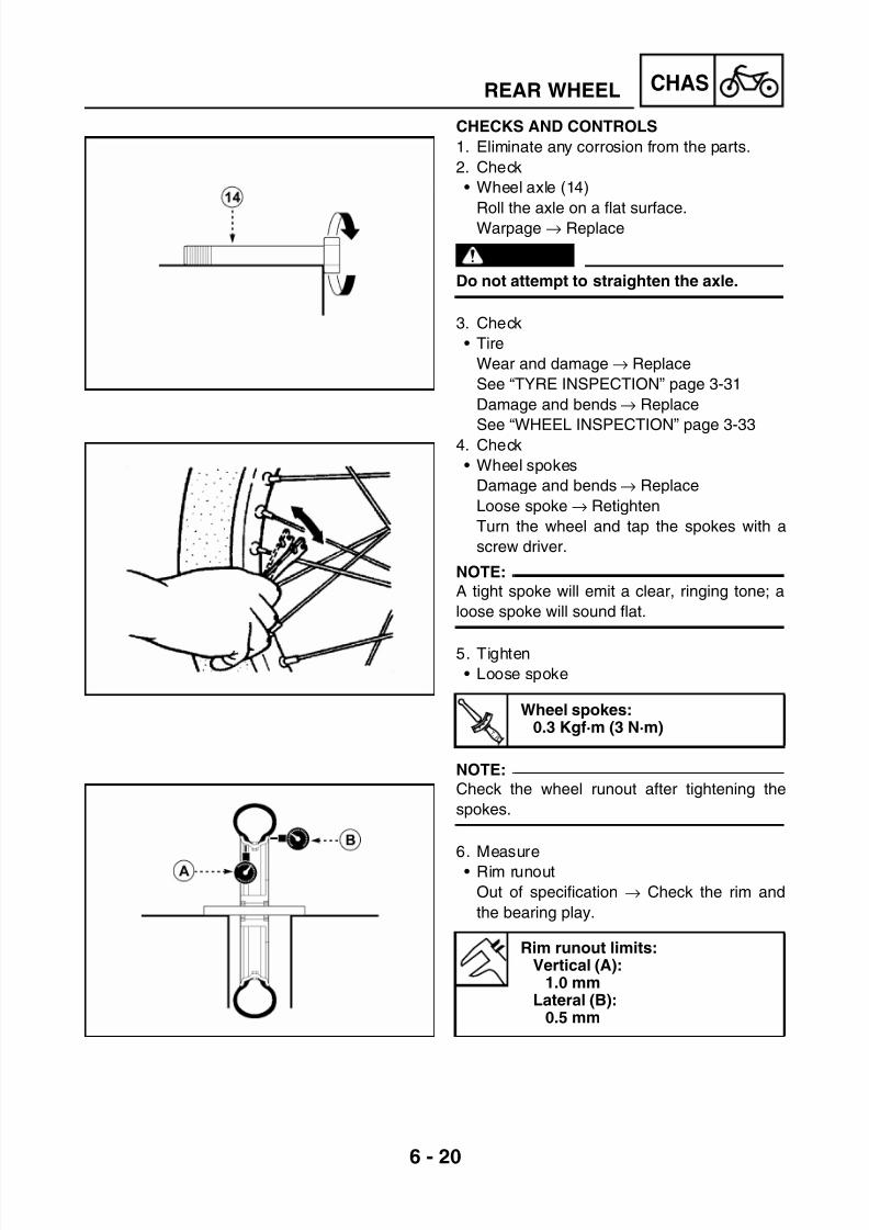
7/22/2019 Yamaha xt 125 service manual
http://slidepdf.com/reader/full/yamaha-xt-125-service-manual 186/279

7/22/2019 Yamaha xt 125 service manual
http://slidepdf.com/reader/full/yamaha-xt-125-service-manual 187/279
6 - 21
CHASREAR WHEEL
WARNING
After mounting a tire, ride conservatively to
allow the tire to be adapted to the rim. Fail-
ure to do so may cause an accident result-
ing in motorcycle damage and possibleoperator injury. After a tire repair or
replacement, be sure to torque tighten the
valve stem locknut (17) to specification.
7. Check
• Bearing (4-9)
Abnormal noise, irregular free play androtation → Replace
(A) side free play
(B) axial free play
*****************************************************
Bearing replacement steps:
• Remove bearings (4-9) using a bearing
puller.
• Install the new bearings
NOTE:
Use a socket wrench (18) that matches the
outside diameter of the bearing.
CAUTION:
Do not strike the centre race (19) or balls
(20) of the bearing. Contact should be
made only with the outer race (21).
*****************************************************
T R .
.
Valve locknut (17):0.3 Kgf·m (3 N·m)
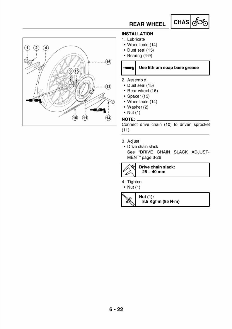
7/22/2019 Yamaha xt 125 service manual
http://slidepdf.com/reader/full/yamaha-xt-125-service-manual 188/279
6 - 22
CHASREAR WHEEL
INSTALLATION
1. Lubricate
• Wheel axle (14)
• Dust seal (15)
• Bearing (4-9)
2. Assemble
• Dust seal (15)
• Rear wheel (16)
• Spacer (13)
• Wheel axle (14)
• Washer (2)
• Nut (1)
NOTE:
Connect drive chain (10) to driven sprocket
(11).
3. Adjust
• Drive chain slack
See “DRIVE CHAIN SLACK ADJUST-
MENT” page 3-26
4. Tighten
• Nut (1)
Use lithium soap base grease
Drive chain slack:
25 ~ 40 mm
T R .
.
Nut (1):8.5 Kgf·m (85 N·m)
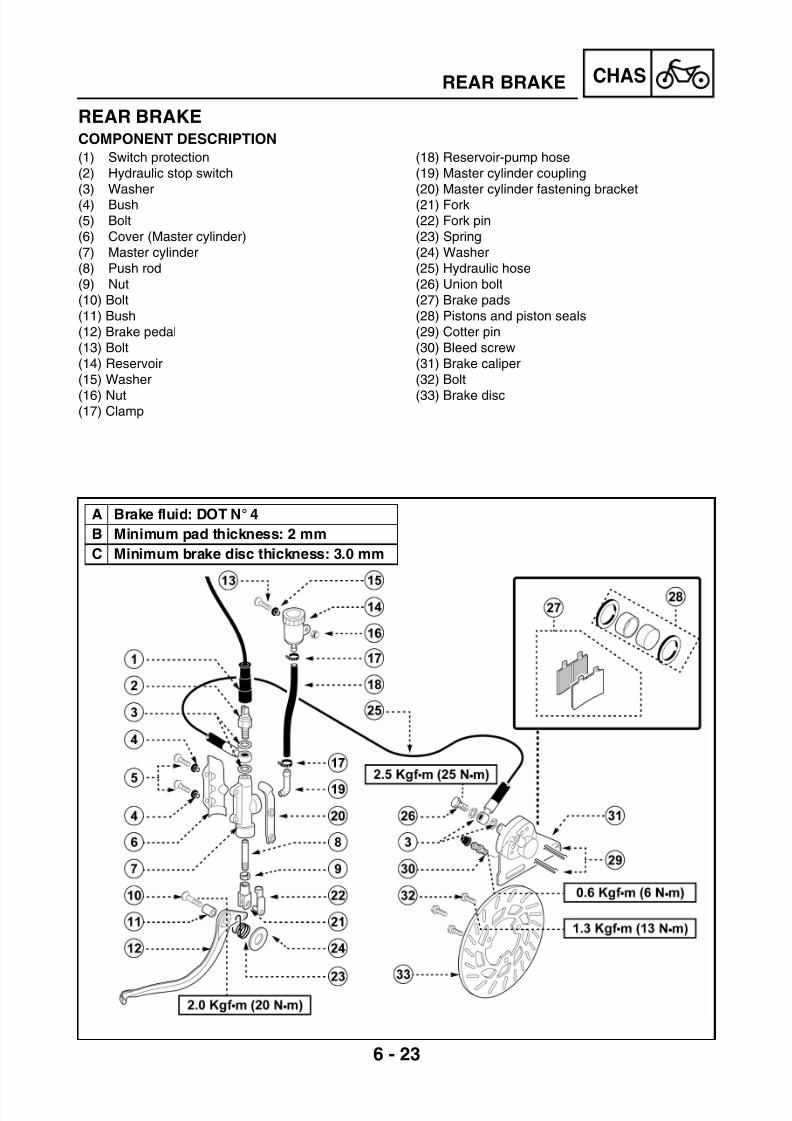
7/22/2019 Yamaha xt 125 service manual
http://slidepdf.com/reader/full/yamaha-xt-125-service-manual 189/279
6 - 23
CHASREAR BRAKE
REAR BRAKECOMPONENT DESCRIPTION
(1) Switch protection(2) Hydraulic stop switch
(3) Washer(4) Bush(5) Bolt(6) Cover (Master cylinder)(7) Master cylinder(8) Push rod(9) Nut(10) Bolt(11) Bush(12) Brake pedal(13) Bolt(14) Reservoir(15) Washer
(16) Nut(17) Clamp
(18) Reservoir-pump hose(19) Master cylinder coupling
(20) Master cylinder fastening bracket(21) Fork(22) Fork pin(23) Spring(24) Washer(25) Hydraulic hose(26) Union bolt(27) Brake pads(28) Pistons and piston seals(29) Cotter pin(30) Bleed screw(31) Brake caliper(32) Bolt
(33) Brake disc
A Brake fluid: DOT N° 4
B Minimum pad thickness: 2 mm
C Minimum brake disc thickness: 3.0 mm

7/22/2019 Yamaha xt 125 service manual
http://slidepdf.com/reader/full/yamaha-xt-125-service-manual 190/279
6 - 24
CHASREAR BRAKE
BRAKE PAD REPLACEMENT
WARNING
Securely support the motorcycle so there
is no danger of it falling over.
1. Remove
• Rear wheel
See “REMOVAL” page 6-19
• Brake caliper (31)
• Cotter pin (29)
• Brake pads (27)
NOTE:
When replacing the pads, replace also spring
retaining clips (27), if necessary.
2. Install
• Brake pads (27)
NOTE:
Be careful when mounting the vibration-proof
plates; the arrow must show the running direc-
tion.
3. Install
• Spring retaining clip (29)
• Brake caliper (31)
• Rear wheel
See “INSTALLATION” page 6-22
4. Check
• Rear brake fluid level
5. Check
• Brake pedal operation
Softy and spongy pedal stroke → Bleed the
brake system.
Minimum pad thickness (A):2 mm

7/22/2019 Yamaha xt 125 service manual
http://slidepdf.com/reader/full/yamaha-xt-125-service-manual 191/279
6 - 25
CHASREAR BRAKE
BRAKE CALIPER DISASSEMBLY
NOTE:
Before disassembling the caliper, drain the
brake system of its brake fluid.
WARNING
Securely support the motorcycle so there
is no danger of it falling over.
1. Remove
• Rear wheel
See “REMOVAL” page 6-19
• Union bolt (26)
• Washer (3)
2. Disconnect• Hydraulic hose (25)
NOTE:
Position the end of hose (25) in a container
and operate the master cylinder to bleed all
fluid.
3. Remove
• Brake caliper (31)
• Cotter pin (29)
• Brake pads (27)4. Remove
• Pistons and piston seals (28)
*****************************************************
Piston and piston seal removal steps:
• Blow compressed air into the hole to push
out the pistons from the caliper.
WARNING
• Do not force out the piston from the cali-
per body.
• Cover the pistons with a rag and use careso that pistons do not cause injury as
they are expelled from the caliper.
CAUTION:
To remove the piston seals, extract them
with your hands and do not use tools.
*****************************************************

7/22/2019 Yamaha xt 125 service manual
http://slidepdf.com/reader/full/yamaha-xt-125-service-manual 192/279
6 - 26
CHASREAR BRAKE
MASTER CYLINDER DISASSEMBLY
NOTE:
Before disassembling the caliper, drain the
brake system of its brake fluid.
WARNING
Securely support the motorcycle so there
is no danger of it falling over.
1. Disconnect
• Hydraulic stop switch (2)
2. Remove
• Hydraulic stop switch (2)
• Washer (3)
• Hydraulic hose (25)• Fork pin (22)
• Clamp (17)
• Oil tank-pump hose (18)
• Bolt (5)
• Bush (4)
• Cover (Master cylinder) (6)
• Master cylinder fastening bracket (20)
NOTE:
Place a container to collect the brake fluid.
INSPECTION AND REPAIR
WARNING
All internal parts should be cleaned in new
brake fluid only. Do not use solvents; they
may cause deformation.
1. Check
• Pistons and piston seals (28)
Bends and wear → Replace
• Brake caliper (31)
Damage → Replace
• Oil delivery passages
Blow out with compressed air

7/22/2019 Yamaha xt 125 service manual
http://slidepdf.com/reader/full/yamaha-xt-125-service-manual 193/279
6 - 27
CHASREAR BRAKE
2. Check
• Master cylinder (7)
Wear and damage → Replace
• Hydraulic hose (25)
Wear and damage→
Replace
3. Measure
• Brake pad thicknessOut of specification → Replace pads
Minimum pad thickness (A):2 mm
4. Check
• Brake disc (33)
Wear and damage → Replace

7/22/2019 Yamaha xt 125 service manual
http://slidepdf.com/reader/full/yamaha-xt-125-service-manual 194/279
6 - 28
CHASREAR BRAKE
5. Measure
• Brake disc deflection
Out of specification → Replace brake disc
• Brake disc thickness
Out of specification → Replace brake disc
NOTE:
Tighten the brake disc bolts in symmetric way.
Maximum brake disc deflection:0.3 mm
Minimum brake disc thickness(C):
0.3 mm
T R .
.
Brake disc bolts:1.3 Kgf·m (13 N·m)Apply sealant “Loctite” on thebolts
ASSEMBLY OF BRAKE CALIPER
WARNING
All internal parts should be cleaned in new
brake fluid only.
1. Install
• Pistons and piston seals (28)
NOTE:
Always use new seals for the caliper pistons.
Recommended brake liquid:DOT N° 4

7/22/2019 Yamaha xt 125 service manual
http://slidepdf.com/reader/full/yamaha-xt-125-service-manual 195/279
6 - 29
CHASREAR BRAKE
2. Install
• Brake pads (27)
NOTE:
Be careful when mounting the vibration-proof
plates; the arrow must show the running direc-tion.
• Cotter pin (29)
• Brake caliper (31)
• Washer (3)
• Hydraulic hose (25)
• Union bolt (26)
WARNING
• Proper brake hose routing is essential to
guarantee safe motorcycle operation.
• Always use new copper washers.
3. Install
• Rear wheel
See “INSTALLATION” page 6-22
4. Fill
• Brake fluid
CAUTION:
Brake fluid may erode painted surfaces or
plastic parts.
WARNING
• Use only the designated quality brakefluid: otherwise, the rubber seals may
deteriorate, causing leakage and poor
brake performance.
• Refill with the same type of brake fluid;
mixing fluids may result in a harmful
chemical reaction and lead to poor perfor-
mance.
• Be careful that water does not enter the
master cylinder when refilling. Water will
significantly lower the boiling point of the
fluid and may result in vapour lock.
T R .
.
Bolt (26):2.5 Kgf·m (25 N·m)
Recommended brake liquid:DOT N° 4

7/22/2019 Yamaha xt 125 service manual
http://slidepdf.com/reader/full/yamaha-xt-125-service-manual 196/279
6 - 30
CHASREAR BRAKE
5. Check
• Rear brake system operation
• Rear brake fluid level
MASTER CYLINDER ASSEMBLY
WARNING
All internal parts should be cleaned in new
brake fluid only.
1. Install
• Master cylinder fastening bracket (20)
• Master cylinder (7)
• Cover (Master cylinder) (6)
• Bush (4)
• Bolt (5)
• Washer (3)
• Hydraulic hose (25)
• Hydraulic stop switch (2)
WARNING
• Proper brake hose routing is essential to
guarantee safe motorcycle operation.
• Always use new copper washers.
2. Connect
• Hydraulic stop switch (2)
3. Install
• Fork pin (22)
• Oil tank-pump hose (18)
• Clamp (17)
4. Fill
• Brake fluid
5. Check
• Rear brake system operation
• Rear brake fluid level
Recommended brake liquid:DOT N° 4
Recommended brake liquid:DOT N° 4

7/22/2019 Yamaha xt 125 service manual
http://slidepdf.com/reader/full/yamaha-xt-125-service-manual 197/279
6 - 31
CHASDRIVE CHAIN AND SPROCKETS
DRIVE CHAIN AND SPROCKETSCOMPONENT DESCRIPTION
(1) Nut(2) Washer
(3) Nut(4) Chain puller adjusting screw(5) Chain puller(6) Rear wheel(7) Drive sprocket(8) Drive sprocket plate(9) Bolt
(10) Nut(11) Drive chain
(12) Driven sprocket(13) Bolt(14) Wheel axle(15) Drive sprocket cover(16) Bolt(17) Spacer
A Drive chain type: 428H G&G DID
BNumber of drive chain links:XT 125 R: 128XT 125 X: 126
C Drive chain slack: 25 ~ 40 mm

7/22/2019 Yamaha xt 125 service manual
http://slidepdf.com/reader/full/yamaha-xt-125-service-manual 198/279
6 - 32
CHASDRIVE CHAIN AND SPROCKETS
CHAIN REMOVAL
NOTE:
Before removing the drive chain and sprock-
ets, measure the drive chain slack.
1. Stand the motorcycle on a level surface.
2. Position a support under the engine and lift
the rear wheel.
3. Remove
• Bolt (16)
• Drive sprocket cover (15)
• Bolt (9)
• Drive sprocket plate (8)
• Drive sprocket (7)
• Rear wheel (6)
See “REMOVAL” page 6-19
4. Remove
• Chain joint pin (17)
• Chain joint (18)
• Drive chain (11)
NOTE:
In case of chain without chain joint, use the
special puller.
CHECKS AND CONTROLS
1. Measure
• Length 10 of links (A)Out of specification → Replace the chain
NOTE:
• The measurement (A) of the 10 links is to be
carried out on the inside edge of roller
from(1) to (11).
• Measure the 10 links in different positions of
the chain.
Chain pin puller:90890-01286
Maximum length of 10 links:119.7 mm

7/22/2019 Yamaha xt 125 service manual
http://slidepdf.com/reader/full/yamaha-xt-125-service-manual 199/279
6 - 33
CHASDRIVE CHAIN AND SPROCKETS
2. Clean
• Drive chain
NOTE:
Place the chain in kerosene, and brush off as
much dirt as possible, and then dry it.
3. Check
• Seized chain linksClean, lubricate or, if necessary, replace the
complete chain.
4. Check
• Drive sprocket
• Driven sprocket
Distance (B) higher than 1/4 of the tooth
thickness → Replace
Damaged teeth → Replace
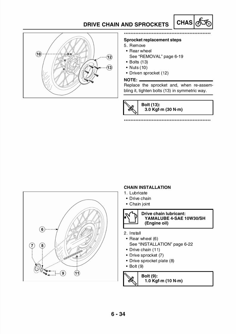
7/22/2019 Yamaha xt 125 service manual
http://slidepdf.com/reader/full/yamaha-xt-125-service-manual 200/279
6 - 34
CHASDRIVE CHAIN AND SPROCKETS
*****************************************************
Sprocket replacement steps
5. Remove
• Rear wheel
See “REMOVAL” page 6-19• Bolts (13)
• Nuts (10)
• Driven sprocket (12)
NOTE:
Replace the sprocket and, when re-assem-
bling it, tighten bolts (13) in symmetric way.
*****************************************************
CHAIN INSTALLATION
1. Lubricate
• Drive chain
• Chain joint
2. Install• Rear wheel (6)
See “INSTALLATION” page 6-22
• Drive chain (11)
• Drive sprocket (7)
• Drive sprocket plate (8)
• Bolt (9)
T R .
.
Bolt (13):3.0 Kgf·m (30 N·m)
Drive chain lubricant:YAMALUBE 4-SAE 10W30/SH(Engine oil)
T R .
.
Bolt (9):1.0 Kgf·m (10 N·m)

7/22/2019 Yamaha xt 125 service manual
http://slidepdf.com/reader/full/yamaha-xt-125-service-manual 201/279
6 - 35
CHASDRIVE CHAIN AND SPROCKETS
3. Install
• Chain joint (18)
• Chain joint pin (17)
CAUTION:
Install chain joint pin 17 in the direction
shown in the figure.
4. Adjust
• Drive chain slack
See “DRIVE CHAIN SLACK ADJUST-
MENT” page 3-26
CAUTION:
Too small chain slack will overload the
engine and other vital parts; keep the slack
within the specified limit.
5. Tighten
• Nut (1)
6. Install
• Drive sprocket cover (15)
• Bolt (16)
Drive chain slack:25 ~ 40 mm
T
R .
.
Nut (1):8.5 Kgf·m (85 N·m)
T R .
.
Bolt (16):1.2 Kgf·m (12 N·m)

7/22/2019 Yamaha xt 125 service manual
http://slidepdf.com/reader/full/yamaha-xt-125-service-manual 202/279
6 - 36
CHASFRONT SUSPENSION
FRONT SUSPENSIONCOMPONENT DESCRIPTION
(1) Protection cap(2) C - clip
(3) Spacer(4) O-Ring(5) Damper rod(6) Spring(7) Fork tube(8) Washer(9) Bush taper(10) Bolt(11) Washer(12) Bolt
(13) Tube outer(14) Oil seal
(15) C - clip(16) Dust seal(17) Steering bottom yoke(18) Bolt(19) Spring(20) Nut(21) Washer(22) Cable holder(23) Bolt
A Oil amount in each fork leg: 285 cc
B Free spring length (19): 495 mm ± 3 mm
COil level on each fork: 180 mmThe oil level is measured from the top of tube (7) completelyinserted into tube holder (13), without spring (19).

7/22/2019 Yamaha xt 125 service manual
http://slidepdf.com/reader/full/yamaha-xt-125-service-manual 203/279

7/22/2019 Yamaha xt 125 service manual
http://slidepdf.com/reader/full/yamaha-xt-125-service-manual 204/279
6 - 38
CHASFRONT SUSPENSION
2. Drain
• Fork oil
3. Remove
• Dust seal (16)
• C - clip (15)
• Oil seal (14)
NOTE:
Use a screwdriver, and be careful not to
scratch fork tube.
4. Remove• Bolt (12)
• Washer (11)
NOTE:To remove bolt (12), lock the tube holder in a
vice and loosen the bolt by means of adapter
(28) and of special “T” wrench (27).
“T” wrench:90890-01326
Adapter:90890-01294

7/22/2019 Yamaha xt 125 service manual
http://slidepdf.com/reader/full/yamaha-xt-125-service-manual 205/279
6 - 39
CHASFRONT SUSPENSION
5. Remove
• Damper rod (5)
• Spring (6)
6. Remove
• Fork tube (7)
*****************************************************Removal steps
• Position the fork in horizontal position.
• Lock tube outer (13) in a vice, by means of
aluminium inserts, in order not to damage
the tube holder surface.
• Extract fork tube (7) strongly and with great
care.
*****************************************************
7. Remove
• Washer (8)
• Bush (9)
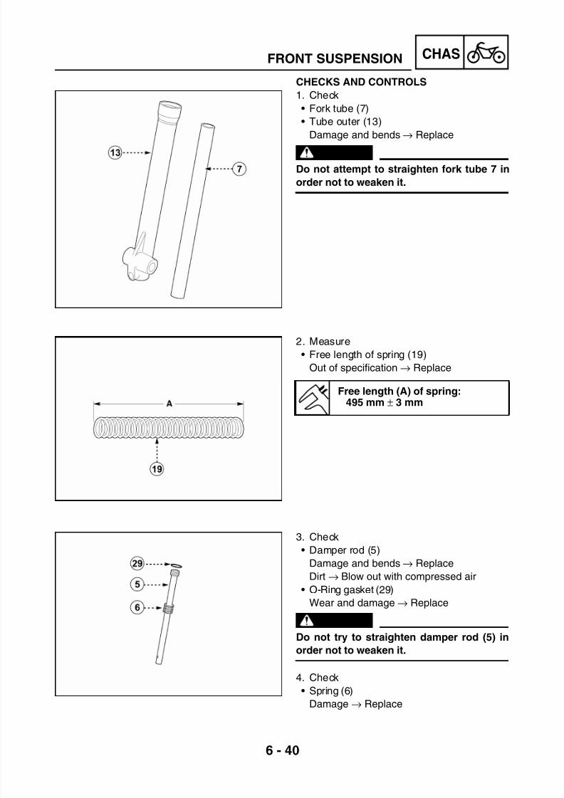
7/22/2019 Yamaha xt 125 service manual
http://slidepdf.com/reader/full/yamaha-xt-125-service-manual 206/279

7/22/2019 Yamaha xt 125 service manual
http://slidepdf.com/reader/full/yamaha-xt-125-service-manual 207/279

7/22/2019 Yamaha xt 125 service manual
http://slidepdf.com/reader/full/yamaha-xt-125-service-manual 208/279
6 - 42
CHASFRONT SUSPENSION
3. Lubricate
• Fork tube (7)
4. Install
• Bush (9)
• Washer (8)
• Fork tube (7)
• Washer (11)
• Bolt (12)
5. Tighten
• Bolt (12)
NOTE:
To tighten bolt (12), lock the outer tube in a
vice and tighten the bolt by means of adapter
(28) and of special “T” wrench (27).
6. Install
• Oil seal (14)
Use puller (29) and adapter (30)
NOTE:
Before installing the oil seal, lubricate the
edges with lithium soap base grease.
Fork oil or equivalent:SAE 10
“T” wrench:90890-01326
Adapter:90890-01294
T R .
.
Bolt (12):2.0 Kgf·m (20 N·m)Apply sealant “Loctite” on thebolts
Puller:
90890-01367Adapter:
90890-01370

7/22/2019 Yamaha xt 125 service manual
http://slidepdf.com/reader/full/yamaha-xt-125-service-manual 209/279
6 - 43
CHASFRONT SUSPENSION
7. Install
• C - clip (15)
NOTE:
Install lock ring (15) in the slot of the tube
holder.
8. Install
• Dust seal (16)
Use puller (29) and adapter (30)
9. Fill
• Fork leg
10.Install
• Spring (19)
• O-Ring (4)
• Spacer (3)• C - clip (2)
• Protection cap (1)
Puller:90890-01367
Adapter:90890-01370
Oil amount in each fork leg:285 ccAfter filling the fork leg with oil,operate it slowly to spread theoil evenly.
Oil level (A) in each fork leg:180 mmThe oil level is measured from
the top of the inner tube, withthe inner tube fully compressedand without the fork spring.

7/22/2019 Yamaha xt 125 service manual
http://slidepdf.com/reader/full/yamaha-xt-125-service-manual 210/279
6 - 44
CHASFRONT SUSPENSION
RH/LH FORK LEG INSTALLATION
1. Install
• RH/LH fork leg (26)
NOTE:
Make sure that the inner fork tube is flush withthe top of top yoke.
2. Tighten
• Bolt (18)
• Bolt (25)
3. Install
• Brake caliper
See “ASSEMBLY OF BRAKE CALIPER”
page 6-14
• Speedometer sensor (24)
• Cable holder (22)
• Front wheel
See “INSTALLATION” page 6-4
• Headlight holder
See “HEADLIGHT HOLDER INSTALLA-
TION” page 3-5
T R .
.
Bolt (18):2.0 Kgf·m (20 N·m)
Bolt (25):2.0 Kgf·m (20 N·m)
T R .
.
Brake caliper bolt:3.0 Kgf·m (30 N·m)
T R .
.
Wheel axle pin:4.5 Kgf·m (45 N·m)

7/22/2019 Yamaha xt 125 service manual
http://slidepdf.com/reader/full/yamaha-xt-125-service-manual 211/279
6 - 45
CHASSTEERING HEAD AND HANDLEBAR
STEERING HEAD AND HANDLEBAR
COMPONENT DESCRIPTION
(1) Bolt(2) Handlebar holder
(3) Throttle cable(4) Protection cap(5) Nut(6) Steering top yoke(7) Bolt(8) Main switch
(9) Lock nut(10) Upper dust seal
(11) Bearings(12) Lower dust seal(13) Steering bottom yoke(14) Bolt(15) Bolt(16) Handlebar
7
9
6
8
7
16
2.0 Kgf.m (20 N.m)
0.7 Kgf.m (7 N.m)
10
11
12
4
13
14
14
2.0 Kgf.m (20 N.m)
3
3.0 Kgf.m (30 N.m)5
2.2 Kgf.m (22 N.m)1
2
2
15
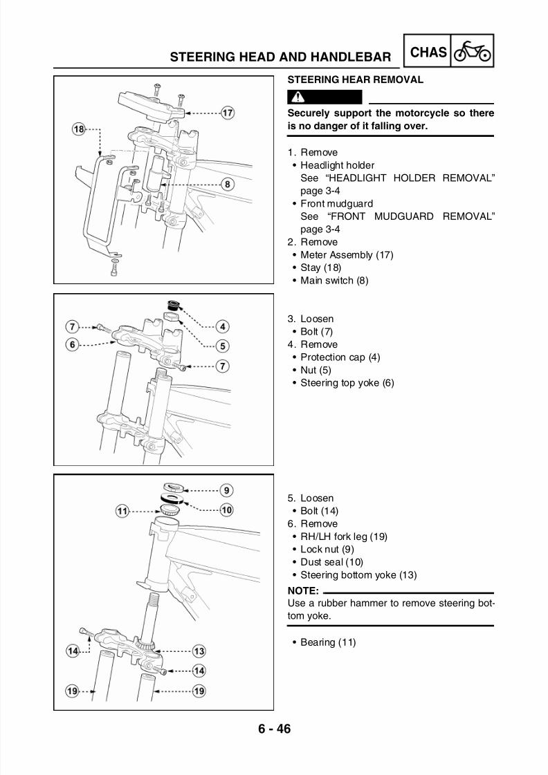
7/22/2019 Yamaha xt 125 service manual
http://slidepdf.com/reader/full/yamaha-xt-125-service-manual 212/279
6 - 46
CHASSTEERING HEAD AND HANDLEBAR
STEERING HEAR REMOVAL
WARNING
Securely support the motorcycle so there
is no danger of it falling over.
1. Remove
• Headlight holder
See “HEADLIGHT HOLDER REMOVAL”
page 3-4
• Front mudguard
See “FRONT MUDGUARD REMOVAL”
page 3-4
2. Remove
• Meter Assembly (17)
• Stay (18)• Main switch (8)
3. Loosen
• Bolt (7)
4. Remove
• Protection cap (4)
• Nut (5)
• Steering top yoke (6)
5. Loosen
• Bolt (14)
6. Remove
• RH/LH fork leg (19)
• Lock nut (9)
• Dust seal (10)
• Steering bottom yoke (13)
NOTE:
Use a rubber hammer to remove steering bot-
tom yoke.
• Bearing (11)

7/22/2019 Yamaha xt 125 service manual
http://slidepdf.com/reader/full/yamaha-xt-125-service-manual 213/279
6 - 47
CHASSTEERING HEAD AND HANDLEBAR
HANDLEBAR REMOVAL
Securely support the motorcycle so there is no
danger of it falling over.
1. Remove
• Grip (20)• Light swich (21)
• Clutch lever (22)
2. Remove
• Throttle twist grip (23)• Engine stop (30)
• Master cylinder (24)
3. Remove
• Handlebar holder (2)
• Handlebar (16)

7/22/2019 Yamaha xt 125 service manual
http://slidepdf.com/reader/full/yamaha-xt-125-service-manual 214/279
6 - 48
CHASSTEERING HEAD AND HANDLEBAR
HANDLEBAR INSPECTION
1. Inspect
• Handlebar
Damage and bends → Replace
WARNINGDo not attempt to straighten a bent handle-
bar, in order not to weaken it
INSPECTION OF STEERING HEAD
1. Wash bearings with kerosene
2. Inspect• Bearing ring (25)
Damage and bends → Replace
• Bearing (11)
Wear and damage → Replace
*****************************************************Race and bearing replacement steps
• Remove races (25) using a long rod and a
hammer.
• Remove bearing (11) from the steering
bottom yoke with a bearing puller (code
90890-02828)
• Replace dust seal (12), if necessary• Install the new bearing with a taper bearing
installing tool (code 90890-02829)
*****************************************************

7/22/2019 Yamaha xt 125 service manual
http://slidepdf.com/reader/full/yamaha-xt-125-service-manual 215/279
6 - 49
CHASSTEERING HEAD AND HANDLEBAR
CAUTION:
A slant installation of the bearing races will
damage the frame, so take care to install
them in horizontal position.
3. Check
• Steering top yoke (6)
• Steering bottom yoke (13)
Damage and bends → Replace
WARNING
Do not try to straighten sleeve (C) of the
steering yoke, if it is deformed, in order not
to weaken it.
STEERING HEAD INSTALLATION
1. Lubricate• Bearing (11)
2. Install
• Upper bearing (11)
• Steering bottom yoke (13)
• Dust seal (10)
• Lock nut (9)
NOTE:Rotate steering bottom yoke (13) to the right
and to the left and check that the motion is cor-
rect. If necessary, loosen or tighten lock nut
(9).
Use lithium soap base grease

7/22/2019 Yamaha xt 125 service manual
http://slidepdf.com/reader/full/yamaha-xt-125-service-manual 216/279
6 - 50
CHASSTEERING HEAD AND HANDLEBAR
3. Install
• Steering top yoke (6)
• Nut (5)
• Protection cap (4)
4. Install
• RH/LH fork leg (19)
5. Tighten
• Bolt (7)
• Bolt (14)
6. Install
• Headlight holder
See “HEADLIGHT HOLDER INSTALLA-
TION” page 3-5
• Front mudguard
See “FRONT MUDGUARD INSTALLA-
TION” page 3-4
HANDLEBAR INSTALLATION
1. Install
• Main switch (8)
• Meter assembly (17)
• Stay (18)
T R .
.
Nut (5):3.0 Kgf·m (30 N·m)
T R .
.
Bolt (7):2.0 Kgf·m (20 N·m)
Bolt (14):2.0 Kgf·m (20 N·m)
T R .
.
Bolt (15):
0.7 Kgf·m (7 N·m)

7/22/2019 Yamaha xt 125 service manual
http://slidepdf.com/reader/full/yamaha-xt-125-service-manual 217/279
6 - 51
CHASSTEERING HEAD AND HANDLEBAR
2. Install
• Handlebar (16)
• Handlebar holder (2)
3. Install
• Master cylinder (24)
• Engine stop (30)
• Throttle twist grip (23)
4. Install
• Grip (20)
• Light switch (21)
• Clutch lever (22)
T R .
.
Bolt (1):2.2 Kgf·m (22 N·m)
T R .
.
Bolt (26):0.6 Kgf·m (6 N·m)
T R .
.
Bolt (27):0.3 Kgf·m (3 N·m)
T R .
.
Bolt (28):
0.5 Kgf·m (5 N·m)
T R .
.
Bolt (29):0.6 Kgf·m (6 N·m)

7/22/2019 Yamaha xt 125 service manual
http://slidepdf.com/reader/full/yamaha-xt-125-service-manual 218/279
6 - 52
CHASREAR SUSPENSION
REAR SUSPENSIONCOMPONENT DESCRIPTION
(1) Bolt(2) Washer
(3) Bolt(4) Nut(5) Washer(6) Nut(7) Washer(8) Engine mount(9) Bolt(10) Nut(11) Shock-absorber(12) Swingarm(13) Nut(14) Bolt(15) Nut
(16) Bolt(17) Chain puller(18) Chain sliding guide
(19) Bush(20) Bolt
(21) Chain guide(22) Bolt(23) Threaded insert(24) Chain case(25) Bolt(26) Bush(27) Bolt(28) Bolt(29) Washer(30) Spacer

7/22/2019 Yamaha xt 125 service manual
http://slidepdf.com/reader/full/yamaha-xt-125-service-manual 219/279
6 - 53
CHASREAR SUSPENSION
RECOMMENDATIONS FOR USE
WARNING
• This shock absorber contains highly
pressurized nitrogen gas. Read and
understand the following informationbefore handling the shock absorber. The
manufacturer cannot be held responsible
for property damage or personal injury
that may result from improper handling.
• Do not tamper with or attempt to open the
shock absorber assembly.
• Do not subject shock absorber to an open
flame or other high heat source. This may
cause the unit to explode due to excessive
gas pressure.• Do not deform or damage the cylinder in
any way. Cylinder damage will result in
poor damping performance.
• In case of disposal, see the instructions
in section “Disposal instructions”.
DISPOSAL INSTRUCTIONS
*****************************************************Shock absorber disposal steps:
• The shock absorber nitrogen gas must be
released before disposing. To do so, drill a 2-3 mm hole through the chamber case at a
15-20 mm distance from the end of the
chamber case.
WARNING
Wear eye protection to prevent eye damage
from escaping gas and/ or metal chips
caused by drilling.
*****************************************************

7/22/2019 Yamaha xt 125 service manual
http://slidepdf.com/reader/full/yamaha-xt-125-service-manual 220/279

7/22/2019 Yamaha xt 125 service manual
http://slidepdf.com/reader/full/yamaha-xt-125-service-manual 221/279
6 - 55
CHASREAR SUSPENSION
SWINGARM REMOVAL
WARNING
Securely support the motorcycle so there
is no danger of it falling over.
1. Stand the motorcycle on a level surface.
2. Disassemble
• Shock absorber lower part
See “SHOCK ABSORBER REMOVAL”
page 6-54
3. Remove
• Chain case (24)
• Chain
See “CHAIN REMOVAL” page 3-32
• Rear wheelSee “REMOVAL” page 6-19
• Cable holder (31)
• Brake caliper
4. Remove
• Nut (4)
• Washer (5)
• Bolt (14)
• Swingarm (12)
5. Remove
• Chain sliding guide (18)
• Chain guide (21)

7/22/2019 Yamaha xt 125 service manual
http://slidepdf.com/reader/full/yamaha-xt-125-service-manual 222/279

7/22/2019 Yamaha xt 125 service manual
http://slidepdf.com/reader/full/yamaha-xt-125-service-manual 223/279
6 - 57
CHASREAR SUSPENSION
SHOCK ABSORBER INSTALLATION
1. Lubricate
• Bush internal surface
2. Install
• Shock-absorber (11) (upper part)
3. Tighten
• Nut (10)
4. Install
• Shock-absorber (11) (lower part)5. Tighten
• Nut (10)
6. Assemble
• Bush (29)
• Bolt (28)
Use lithium soap base grease
T R .
.
Nut (10) (upper part):4.5 Kgf·m (45 N·m)
T R .
.
Nut (10) (lower part):4.5 Kgf·m (45 N·m)

7/22/2019 Yamaha xt 125 service manual
http://slidepdf.com/reader/full/yamaha-xt-125-service-manual 224/279
6 - 58
CHASREAR SUSPENSION
SWINGARM INSTALLATION
1. Lubricate
• Bush internal surface
2. Assemble
• Chain sliding guide (18)
• Chain guide (21)
3. Lubricate• Bolt (14)
4. Assemble
• Swingarm (12)
• Bolt (14)
• Washer (5)
• Nut (4)
5. Tighten
• Nut (4)
6. Assemble
• Brake caliper
• Cable holder (31)
• Rear wheel
See “INSTALLATION” page 6-22
• Chain
See “CHAIN INSTALLATION” page 6-34
• Chain case (24)
7. Connect
• Shock absorber lower part
See “SHOCK ABSORBER INSTALLA-
TION” page 6-57
Use lithium soap base grease
Use lithium soap base grease
T R .
.
Nut (4):6.0 Kgf·m (60 N·m)
T R .
.
Bolt (26-27):0.7 Kgf·m (7 N·m)

7/22/2019 Yamaha xt 125 service manual
http://slidepdf.com/reader/full/yamaha-xt-125-service-manual 225/279
– +ELEC
CHAPTER 7
ELECTRICAL SYSTEM
ELECTRICAL SYSTEM...................................................................................7-1CIRCUIT DIAGRAM ..................................................................................7-1COLOUR CODE........................................................................................7-2
ELECTRICAL COMPONENTS........................................................................7-3
CHECKING THE CONNECTIONS ..................................................................7-4
CHECKING THE SWITCHES..........................................................................7-5CHECKING STEPS...................................................................................7-5SWITCH CONNECTIONS AS SHOWN IN THIS MANUAL ......................7-5
IGNITION SYSTEM .........................................................................................7-6CIRCUIT DIAGRAM ..................................................................................7-6TROUBLESHOOTING ..............................................................................7-7
ELECTRICAL STARTING SYSTEM .............................................................7-11CIRCUIT DIAGRAM ................................................................................7-11LIST OF COMPONENTS ........................................................................ 7-18STARTER MOTOR REMOVAL...............................................................7-19
STARTER MOTOR DISASSEMBLY....................................................... 7-19INSPECTION AND REPAIR....................................................................7-19STARTER MOTOR ASSEMBLY............................................................. 7-21STARTER MOTOR ASSEMBLY............................................................. 7-22
CHARGING SYSTEM....................................................................................7-23CIRCUIT DIAGRAM ................................................................................7-23TROUBLESHOOTING ............................................................................7-24
LIGHTING SYSTEM ......................................................................................7-27
CIRCUIT DIAGRAM ................................................................................7-27TROUBLESHOOTING ............................................................................7-28
LIGHTING SYSTEM ......................................................................................7-30LIGHTING SYSTEM CHECK .................................................................. 7-30

7/22/2019 Yamaha xt 125 service manual
http://slidepdf.com/reader/full/yamaha-xt-125-service-manual 226/279
– +ELEC
SIGNAL SYSTEM..........................................................................................7-32CIRCUIT DIAGRAM ................................................................................7-32TROUBLESHOOTING ............................................................................7-33CHECKING THE SIGNAL SYSTEM .......................................................7-35
CARBURETOR HEATER SYSTEM ..............................................................7-47CIRCUIT DIAGRAM ................................................................................7-47CHECKING THE CARBURETOR HEATER CIRCUIT ANDTHERMAL SENSOR .............................................................................. 7-48CARBURETOR HEATER CIRCUIT ........................................................ 7-48

7/22/2019 Yamaha xt 125 service manual
http://slidepdf.com/reader/full/yamaha-xt-125-service-manual 227/279
7 - 1
– +ELEC
ELECTRICAL SYSTEMELECTRICAL SYSTEMCIRCUIT DIAGRAM
ELECTRICAL SYSTEM

7/22/2019 Yamaha xt 125 service manual
http://slidepdf.com/reader/full/yamaha-xt-125-service-manual 228/279

7/22/2019 Yamaha xt 125 service manual
http://slidepdf.com/reader/full/yamaha-xt-125-service-manual 229/279
7 - 3
– +ELECELECTRICAL COMPONENTS
ELECTRICAL COMPONENTS(1) Main switch
(2) Digital meter assembly
(3) Carburetor heater
(4) Regulator(5) Starting relay
(6) Turn signal relay
(7) Thermal sensor
(8) Battery
(9) “CDI” control unit
(10) Fuse 10A
(11) Coil(12) Rear stop switch
(13) Front stop switch
(14) Horn

7/22/2019 Yamaha xt 125 service manual
http://slidepdf.com/reader/full/yamaha-xt-125-service-manual 230/279
7 - 4
– +ELECCHECKING THE CONNECTIONS
CHECKING THE CONNECTIONSCheck for rust and moisture in connectors
1. Disconnect
• Connectors
2. Dry each terminal with an air blower.
3. Connect and disconnect the connector two
or three times.
4. Pull the connector to check that it will not
come off.
5. If the terminal comes off, bend up pin (A)
and reinsert the terminal into the connector.
6. Connect
• Connectors
NOTE:
The connector parts are assembled properly
when they “click” together.
7. Check for continuity with a Tester.
NOTE:
• If there is no continuity, clean the terminals.
• Be sure to perform the steps 1 to 7 when
checking the electrical system.
• For a field remedy, use a contact cleaner.
• Use the Tester as shown in figure.

7/22/2019 Yamaha xt 125 service manual
http://slidepdf.com/reader/full/yamaha-xt-125-service-manual 231/279
7 - 5
– +ELECCHECKING THE SWITCHES
CHECKING THE SWITCHESCHECKING STEPS
Use a Tester to check the terminals for conti-
nuity and for proper connection. If the continu-
ity is faulty at any point, replace thecomponent.
NOTE:
• Turn switch “ON-OFF” to “ON” and “OFF”
several times
• Set the Tester selector to “Ω”.
• Set the indicator to “0”.
Tester:90890-01312
SWITCH CONNECTIONS AS SHOWN IN
THIS MANUAL
This manual contains the connection charts
(as shown left) showing the switch terminals
(e.g., main switch, brake switch, lighting
switch, etc.)The left column indicates the different switch
positions; the top line indicates the colours of
the conductors connected to the switch termi-
nals.
“∞” indicates the continuity between terminals;
i.e., a closed circuit at the special switch posi-
tions.
In this chart, “Br” and “R” are continuous when
the switch is set to “ON”.

7/22/2019 Yamaha xt 125 service manual
http://slidepdf.com/reader/full/yamaha-xt-125-service-manual 232/279

7/22/2019 Yamaha xt 125 service manual
http://slidepdf.com/reader/full/yamaha-xt-125-service-manual 233/279
7 - 7
– +ELECIGNITION SYSTEM
TROUBLESHOOTING
Check1. Fuse 10A
2. Battery
3. Spark plug
4. Spark
5. Spark plug cap resistance
6. H.T. coil resistance
7. Main switch
8. Charge coil resistance
9. Pick-up resistance
10. Ignition system connections
NOTE:
• For these operations use the following tools:
THE IGNITION SYSTEM FAILS TO OPERATE(NO SPARK OR INTERMITTENT SPARK)
Dynamic spark tester:90890-06754
Tester:90890-03112
NO CONTINUITY
Faulty fuse → Replace
INCORRECT
• Clean the terminals
• Recharge or replace battery
• Refill with distilled water
CONTINUITY
1. Fuse 10A
• Remove the fuse
• Connect Tester “Ω” to the fuse
• Check the fuse for continuity
See “FUSE INSPECTION 10A” page 3-36
CORRECT
2. Battery
• Check the battery conditions:
Minimum voltage: 12.5 V
Specific gravity: 1280 g/dm3
Electrolyte level

7/22/2019 Yamaha xt 125 service manual
http://slidepdf.com/reader/full/yamaha-xt-125-service-manual 234/279
7 - 8
– +ELEC
CORRECT
Operating ignition system
INCORRECT
Faulty spark plug→ Replace or adjust the
electrolyte gap
INCORRECT
Faulty spark plug cap → Replace
CORRECT
3. Spark plug
• Check the spark plug conditions
• Check the spark plug type
• Check the electrolyte gap
See “SPARK PLUG INSPECTION” page
3-13
Electrode gap:0.7 mm
INCORRECT
4. Spark
• Disconnect the spark plug connector
• Connect spark dynamic tester (1)
• Spark plug (2)
• Turn the main switch to “ON”
• Check the electrolyte gap (A)
• Start the engine and increase the spark gap
until the spark is eliminated.
Minimum gap: 6.0 mm
CORRECT
5. Spark plug cap resistance
• Remove the spark plug cap
NOTE:
When removing cap “KΩ” do not pull the
spark plug lead
• Connect Tester as shown in figure
Removal → Turn counterclockwise
Installation → Turn clockwise
• During connection, check the spark plug
lead and, if necessary, replace it with a new
one.
Cap resistance:5 KΩ ± 20% at 20°C
IGNITION SYSTEM
Standard spark plug:NGK CR7HSA or DENSO U22
FSR-U
Terminal (+) → Spark plug side (1)
Terminal (-) → Spark plug lead side (2)

7/22/2019 Yamaha xt 125 service manual
http://slidepdf.com/reader/full/yamaha-xt-125-service-manual 235/279
7 - 9
– +ELEC
INCORRECT
Faulty ignition coil → Replace
CORRECT
CORRECT
6. H.T. coil resistance
• Disconnect orange lead• Connect Tester “Ω” to H.T. coil
• Check the primary coil resistance
Primary coil resistance:0.3 Ω ± 10% at 20°C
• Connect Tester “KΩ” to H.T. coil
• Check the secondary coil resistance
Secondary coil resistance:3.16 KΩ ± 10% at 20°C
7. Main switch
• Disconnect the main switch from the sys-
tem
• Turn the main switch to “ON”
• Connect Tester “Ω” and check leads for
continuity
Orange (1) → Green (2)
See “CHECKING THE SWITCHES” page7-5
IGNITION SYSTEM
Terminal (+) → Terminal (1)
Terminal (-) → Earthed (2)
Terminal (+) → Spark plug lead (1)
Terminal (-) → Terminal (2)
INCORRECT
Faulty main switch → Replace

7/22/2019 Yamaha xt 125 service manual
http://slidepdf.com/reader/full/yamaha-xt-125-service-manual 236/279
7 - 10
– +ELEC
INCORRECT
Replace the stator assembly
INCORRECT
Repair the system wiring
INCORRECT
Replace the stator assembly
IGNITION SYSTEM
CORRECT
CORRECT
CORRECT
8. Charge coil resistance
• Disconnect four-way connector (1) ofmagneto flywheel (2)
• Connect Tester “Ω” to the connector as
follows
Terminal (+) → White terminal (3)
Terminal (-) → Black terminal (4)
• Check the charge coil resistance
Charge coil resistance:0.80 Ω ± 20% at 20°C
9. Pick-up resistance
• Disconnect two-way connector (1) of
magneto flywheel (2)
• Connect Tester “Ω” to the connector as
follows
Terminal (+) → Green terminal (3)
Terminal (-) → Blue-yellow terminal (4)
• Check the pick-up resistance
Pick-up resistance:240 Ω ± 20% at 20°C
10. Wiring connections
• Check the ignition system for connections
See “CIRCUIT DIAGRAM” page 7-1
Replace the “CDI” control unit
1
2
4
3

7/22/2019 Yamaha xt 125 service manual
http://slidepdf.com/reader/full/yamaha-xt-125-service-manual 237/279
7 - 11
– +ELECELECTRICAL STARTING SYSTEM
ELECTRICAL STARTING SYSTEMCIRCUIT DIAGRAM
(1) Battery(2) Fuse 10A
(3) Starting relay(4) Starter(5) Clutch switch
(6) Neutral position switch(7) Main switch
(8) Starting button(9) “Engine stop” button(10) Side stand switch

7/22/2019 Yamaha xt 125 service manual
http://slidepdf.com/reader/full/yamaha-xt-125-service-manual 238/279

7/22/2019 Yamaha xt 125 service manual
http://slidepdf.com/reader/full/yamaha-xt-125-service-manual 239/279
7 - 13
– +ELEC
NO CONTINUITY
Faulty fuse → Replace
ELECTRICAL STARTING SYSTEM
INCORRECT
• Clean the terminals
• Recharge or replace battery
• Refill with distilled water
TROUBLESHOOTING
Check
(1) Fuse 10A
(2) Battery
(3) Starter
(4) Starting relay
(5) Main switch
(6) Neutral position switch
(7) Clutch switch
(8) Starting button
(9) “Engine stop” button
(10) Side stand switch
(11) Wiring connections
NOTE:
• For these operations use the following tools:
THE STARTER MOTOR FAILS TO OPERATE
T R .
.
Tester:90890-03112
CORRECT
CONTINUITY
1. Fuse 10A
• Remove the fuse• Connect Tester “Ω” to the fuse
• Check the fuse for continuity
2. Battery
• Check the battery conditions
See “BATTERY INSPECTION” page 3-35Minimum voltage: 12.5 V
Specific gravity: 1280 g/dm3
Electrolyte level

7/22/2019 Yamaha xt 125 service manual
http://slidepdf.com/reader/full/yamaha-xt-125-service-manual 240/279
7 - 14
– +ELEC
THE STARTER FAILS TO TURN
Faulty starter relay → Replace
THE STARTER FAILS TO TURN
Faulty starter motor → Repair or replace
ELECTRICAL STARTING SYSTEM
WARNING
A wire for the jumper lead must have the
equivalent capacity as that of the battery
lead or more, otherwise it may cause the
jumper lead to be burned.
CAUTION:
• Take care not to reverse the battery con-
nections because the diode will be da-
maged.• Take care to avoid shorting the positive
and negative terminals when connecting
the battery to the relay.
THE STARTER
TURNS
THE STARTER
TURNS
3. Starter
• Connect battery positive terminal (1) andstarter motor cable (2) using a jumper lead
(3) as shown in figure.
• Check the starter motor for operation.
4. Starting relay
• Disconnect the starter relay
• Connect the battery to the starting relay
with jumper leads (1)Battery lead (+) → White-red lead
Battery lead (-) → Red-black lead
• Check the starter motor for operation.

7/22/2019 Yamaha xt 125 service manual
http://slidepdf.com/reader/full/yamaha-xt-125-service-manual 241/279
7 - 15
– +ELEC
INCORRECT
Faulty neutral switch → Replace
INCORRECT
Faulty main switch → Replace
ELECTRICAL STARTING SYSTEM
CORRECT
CORRECT
5. Main switch
• Disconnect the main switch• Turn the main switch to “ON”
• Connect Tester “Ω” and check leads for
continuity
Orange lead → Green lead
See “CHECKING THE SWITCHES” page 7-5
6. Neutral position switch• Connect Tester “Ω” and check the continu-
ity between neutral switch (1) and chassis
ground (2).
Idle run → Continuity
Engaged gear → No continuity

7/22/2019 Yamaha xt 125 service manual
http://slidepdf.com/reader/full/yamaha-xt-125-service-manual 242/279
7 - 16
– +ELEC
INCORRECT
Faulty starting switch → Replace
ELECTRICAL STARTING SYSTEM
INCORRECT
Faulty clutch switch → Replace
CORRECT
CORRECT
7. Clutch switch
• Disconnect clutch switch (1)• Connect Tester “Ω” and check the terminals
for continuity.
Terminal (T1) → Terminal (T2)
See “CHECKING THE SWITCHES” page
7-5
8. Starting button (start)
• Disconnect four-pin connector (1)
• Connect Tester “Ω” and check leads for
continuity
Green-black lead (2) → White-green lead
(3)
See “CHECKING THE CONNECTIONS”
page 7-4
1 Clutch lever notpulled
2 Clutch lever pulled

7/22/2019 Yamaha xt 125 service manual
http://slidepdf.com/reader/full/yamaha-xt-125-service-manual 243/279
7 - 17
– +ELECELECTRICAL STARTING SYSTEM
INCORRECT
Faulty “engine stop” button → Replace
INCORRECT
Faulty side stand switch → Replace
INCORRECT
Restore or correct
CORRECT
CORRECT
9. “Engine stop” button
• Disconnect four-pin connector (1)• Connect Tester “Ω” and check leads for
continuity
White-black lead (2) → Black lead (3)
See “CHECKING THE CONNECTIONS”
page 7-4
10. Side stand switch
• Disconnect two-pin connector (1) of the
side stand
• Connect Tester “Ω” to the connector as
follows
Terminal (+) → Terminal (2)
Terminal (-) → Terminal (3)
11. Wiring connections
• Check the ignition system for connections
See “CIRCUIT DIAGRAM” page 7-11

7/22/2019 Yamaha xt 125 service manual
http://slidepdf.com/reader/full/yamaha-xt-125-service-manual 244/279
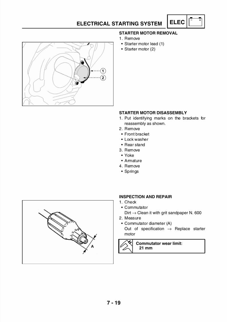
7/22/2019 Yamaha xt 125 service manual
http://slidepdf.com/reader/full/yamaha-xt-125-service-manual 245/279
7 - 19
– +ELECELECTRICAL STARTING SYSTEM
STARTER MOTOR REMOVAL
1. Remove
• Starter motor lead (1)
• Starter motor (2)
STARTER MOTOR DISASSEMBLY1. Put identifying marks on the brackets for
reassembly as shown.
2. Remove
• Front bracket
• Lock washer
• Rear stand
3. Remove
• Yoke
• Armature
4. Remove
• Springs
INSPECTION AND REPAIR
1. Check
• Commutator
Dirt → Clean it with grit sandpaper N. 600
2. Measure
• Commutator diameter (A)
Out of specification → Replace starter
motor
Commutator wear limit:21 mm

7/22/2019 Yamaha xt 125 service manual
http://slidepdf.com/reader/full/yamaha-xt-125-service-manual 246/279
7 - 20
– +ELECELECTRICAL STARTING SYSTEM
3. Measure
• Mica undercut (a)
Out of specification → Scrape the mica to
proper value by using a hacksaw blade
NOTE:
The mica insulation of the commutator must be
undercut to ensure the proper operation of the
commutator.
Mica undercut:1.5 mm
4. Check
• Armature coil (insulation/continuity)
Defects → Replace starter motor
*****************************************************
Checking steps
• Connect the Tester, as shown in the figure,
for continuity check (1) and insulation check
(2).
• Measure the armature resistance• If the resistance is not correct, replace the
starter motor.
*****************************************************
Measure the armature coil:Continuity check (1)
0.017 ~ 0.021 W at 20°CInsulation check (2)
More than 1 M W at 20°C
5. Measure
• Brush length (A)
Out of specification → Replace the assem-
bly
NOTE:
When replacing the brushes make sure thatthe brush side is correct.
Brush length limit:3.5 mm

7/22/2019 Yamaha xt 125 service manual
http://slidepdf.com/reader/full/yamaha-xt-125-service-manual 247/279
7 - 21
– +ELECELECTRICAL STARTING SYSTEM
6. Measure
• Brush spring force
Out of specification → Replace the assem-
bly
7. Check
• Circlip
• Bearing
• Bush
Defects → Replace the bracket
• O-Ring gasket
Wear and damage → Replace
Spring force:560 ~ 840 g
STARTER MOTOR ASSEMBLY
1. Install
• Spring
• Brushes
NOTE:
When installing the brush, pass the brush lead
outside the projection on the brush springholder.
Install the brush lead terminal to touch lightly
the projection on the side of brush spring
holder.
2. Install
• Armature (1)
NOTE:
When installing the armature, press the
brushes with a thin screwdriver to avoid dam-
age.
3. Install
• O-Ring gasket
WARNING
Always use new O-Rings.
4. Install
• Yoke
NOTE:Align the match mark on the yoke with the
match mark on the rear bracket.

7/22/2019 Yamaha xt 125 service manual
http://slidepdf.com/reader/full/yamaha-xt-125-service-manual 248/279
7 - 22
– +ELECELECTRICAL STARTING SYSTEM
5. Install
• Lock washer
• Shim
• Front bracket
NOTE:• Align the projection of the washer with the
slot of the front bracket and install it.
• Align the match marks on the yoke with the
match marks on the brackets.
T R .
.
Bolt:0.5 Kgf·m (5 N·m)
STARTER MOTOR ASSEMBLY
1. Install
• Starter motor (2)
• Starter motor lead (1)
T R .
.
Starter motor bolt:0.7 Kgf·m (7 N·m)

7/22/2019 Yamaha xt 125 service manual
http://slidepdf.com/reader/full/yamaha-xt-125-service-manual 249/279
7 - 23
– +ELECCHARGING SYSTEM
CHARGING SYSTEMCIRCUIT DIAGRAM
(1) CDI magneto(2) Regulator
(3) Battery(4) Fuse 10A
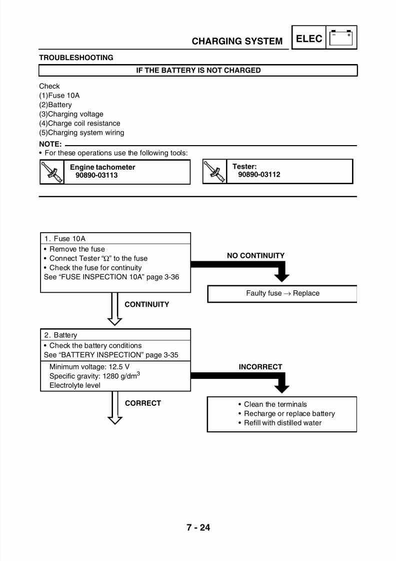
7/22/2019 Yamaha xt 125 service manual
http://slidepdf.com/reader/full/yamaha-xt-125-service-manual 250/279
7 - 24
– +ELECCHARGING SYSTEM
TROUBLESHOOTING
Check
(1)Fuse 10A(2)Battery
(3)Charging voltage
(4)Charge coil resistance
(5)Charging system wiring
NOTE:
• For these operations use the following tools:
IF THE BATTERY IS NOT CHARGED
T R .
.
Engine tachometer90890-03113 T R .
.
Tester:90890-03112
CORRECT
INCORRECT
• Clean the terminals
• Recharge or replace battery
• Refill with distilled water
CONTINUITY
NO CONTINUITY
Faulty fuse → Replace
1. Fuse 10A
• Remove the fuse
• Connect Tester “Ω” to the fuse
• Check the fuse for continuity
See “FUSE INSPECTION 10A” page 3-36
2. Battery
• Check the battery conditions
See “BATTERY INSPECTION” page 3-35
Minimum voltage: 12.5 V
Specific gravity: 1280 g/dm3
Electrolyte level

7/22/2019 Yamaha xt 125 service manual
http://slidepdf.com/reader/full/yamaha-xt-125-service-manual 251/279
7 - 25
– +ELEC
CORRECT
The charging circuit operates properly
CHARGING SYSTEM
INCORRECT
INCORRECT
3. Charging voltage
• Connect the engine tachometer to thespark plug lead.
• Connect Tester DC 20V to the battery.
Terminal (+) → Battery terminal (+)
Terminal (-) → Battery terminal (+)
• Measure the battery voltage
• Start the engine and accelerate to 5000
rpm.
• Check the battery voltage.
Charging voltage:12.5 ~ 14.5 V
NOTE:Measure the battery voltage
Use a fully charged battery.
3.1. Current consumption check
• Disconnect red lead from pole + of thebattery
• Do not disconnect the black lead from pole
- of the battery
• Connect Tester DC 10A to pole + of the
battery and to red lead
Terminal (+) → Battery red lead
Terminal (-) → Battery terminal (+)
• When the main switch is in position “OFF”
the measured value must correspond to “0”
• If current consumption is detected, it will benecessary to find the cause and to repair
wiring.
• Start the engine and accelerate to 3500
rpm. If the charging current is above zero
“0”, the charging system is normal.
WARNING
Make sure that the (+) lead is in contact with
the (+) terminal of the battery during start up
of machine or demage to the tester will
occur.

7/22/2019 Yamaha xt 125 service manual
http://slidepdf.com/reader/full/yamaha-xt-125-service-manual 252/279
7 - 26
– +ELEC
INCORRECT
Repair the system wiring
INCORRECT
Replace the yoke
CHARGING SYSTEM
CORRECT
CORRECT
4. Charge coil resistance
• Disconnect four-way connector (1) of mag-neto flywheel (2)
• Connect Tester “Ω” to the connector as fol-
lows
Terminal (+) → White lead terminal (3)
Terminal (-) → Black lead terminal (4)
• Measure the charge coil resistance
Charge coil resistance:0.80 Ω ± 20% at 20°C
5. Charging system wiring
• Check the charging system wiring
See “CIRCUIT DIAGRAM” page 7-23
Replace the voltage regulator

7/22/2019 Yamaha xt 125 service manual
http://slidepdf.com/reader/full/yamaha-xt-125-service-manual 253/279
7 - 27
– +ELECLIGHTING SYSTEM
LIGHTING SYSTEMCIRCUIT DIAGRAM
(1) CDI magneto(2) Regulator
(3) Meter assembly(4) Left control unit
(5) High and low beam indicator light(6) Side light
(7) Tail brake and stop light(8) Licence light

7/22/2019 Yamaha xt 125 service manual
http://slidepdf.com/reader/full/yamaha-xt-125-service-manual 254/279
7 - 28
– +ELEC
INCORRECT
Replace the yoke
LIGHTING SYSTEM
TROUBLESHOOTING
Check
(1) Lighting coil resistance
(2) Pink lead continuity
(3) Light switch (left control)
(4) Lighting system wiring
NOTE:
• For these operations use the following tools:
THE HEADLIGHT, THE HIGH BEAM INDICATOR LIGHT, THE TAILLIGHT AND/OR THEMETER ASSEMBLY LIGHTS FAIL TO COME ON
Tester:90890-03112
CORRECT
1. Lighting coil resistance
• Disconnect four-way connector (1) of mag-
neto flywheel (2)
• Connect Tester “Ω” to the connector as fol-
lows
Terminal (+) → Yellow lead terminal (3)
Terminal (-) → Black lead terminal (4)
• Measure the lighting coil resistance
Lighting coil resistance:0.6 Ω ± 20% at 20°C

7/22/2019 Yamaha xt 125 service manual
http://slidepdf.com/reader/full/yamaha-xt-125-service-manual 255/279
7 - 29
– +ELEC
NO CONTINUITY
Faulty pink lead, repair wiring
See “CIRCUIT DIAGRAM” page 7-27
INCORRECT
Repair the system wiring
NO CONTINUITY
Replace the left control unit
LIGHTING SYSTEM
CONTINUITY
CORRECT
CONTINUITY
2. Pink lead continuity check
• Disconnect the regulator connector• Disconnect four-way connector of magneto
flywheel
• Connect Tester “Ω” between the flywheel
connector pink lead (system side) and the
regulator connector pink lead.
3. Check light switch• Disconnect nine-way connector of left control
• Connect Tester “Ω” to the left control con-
nector
• Position the lighting button on the symbol
(high beam) and check continuity as
follows:
Terminal (+) → Pink lead
Terminal (-) → White-black lead
• Position the button on the symbol (low
beam) and check continuity as follows:Terminal (+) → Pink lead
Terminal (-) → White-blue lead
4. Lighting system wiring
• Check all connections of the lighting system
See “CIRCUIT DIAGRAM” page 7-27
Replace the voltage regulator

7/22/2019 Yamaha xt 125 service manual
http://slidepdf.com/reader/full/yamaha-xt-125-service-manual 256/279
7 - 30
– +ELEC
NO CONTINUITY
Replace bulb or bulb socket
LIGHTING SYSTEM
LIGHTING SYSTEMLIGHTING SYSTEM CHECK
THE LOW/HIGH BEAM INDICATOR LIGHT AND THEIR PILOT LIGHTS FAIL TO COME ON
CONTINUITY
CORRECT
1. Bulb and bulb socket
• Check the bulb and bulb socket for continuity
2. Checking the light holder and meter
assembly voltage
• Connect Tester AC 20V to the headlight
and meter assembly connector
(A) Checking the low beam indicator light
Terminal (+) → Blue-white lead
Terminal (-) → Black lead
(B) Checking the high beam indicator light
Terminal (+) → White-black lead
Terminal (-)→ Black lead
(C) Checking the high beam indicator light and
pilot lightTerminal (+) → White-black lead (pin 11)
Terminal (+)→ Pink lead (pin 9)
Terminal (-)→ Black lead (pin 1)
• Start the engine and press the button to acti-
vate the high and low beam indicator lights.
• The voltage measured during checks A-B-C
must correspond to 12.5V
The circuit is not faulty
INCORRECT
Repair the connections of the front head-
light and the meter assembly light
See “CIRCUIT DIAGRAM” page 7-27

7/22/2019 Yamaha xt 125 service manual
http://slidepdf.com/reader/full/yamaha-xt-125-service-manual 257/279
7 - 31
– +ELEC
NO CONTINUITY
Replace bulb or bulb socket
LIGHTING SYSTEM
INCORRECT
Repair connections between regulator,
left control and taillight connector
See “CIRCUIT DIAGRAM” page 7-27
THE TAILLIGHT FAILS TO COME ON
CORRECT
CONTINUITY
1. Bulb and bulb socket
• Check the bulb and bulb socket for continu-
ity
2. Checking the light holder voltage
• Connect Tester AC 20V to the bulb socket
terminals
Terminal (+) → Pink lead terminal
Terminal (-) → Black lead terminal
• Start the engine.
• The measured voltage must be 12.5V
The circuit is not faulty
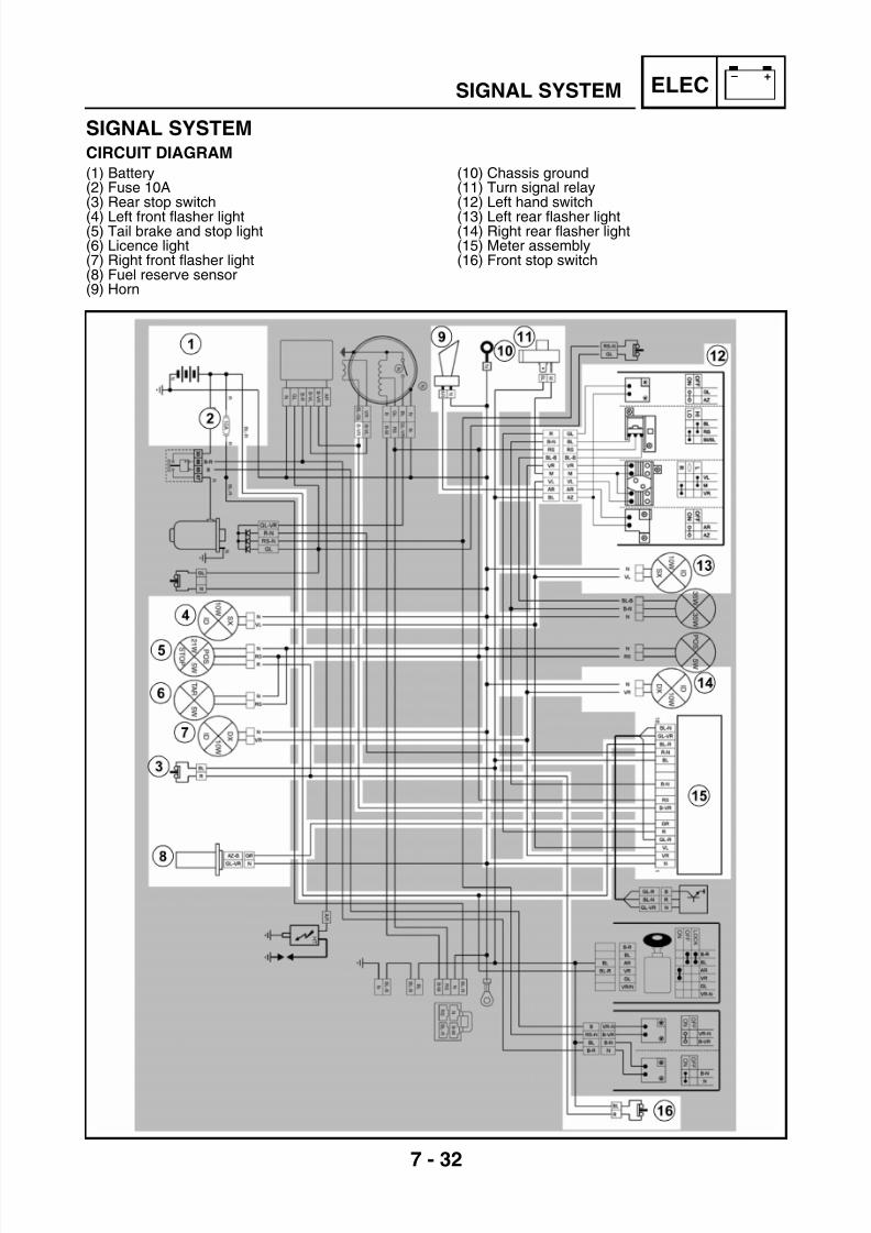
7/22/2019 Yamaha xt 125 service manual
http://slidepdf.com/reader/full/yamaha-xt-125-service-manual 258/279
7 - 32
– +ELECSIGNAL SYSTEM
SIGNAL SYSTEMCIRCUIT DIAGRAM
(1) Battery(2) Fuse 10A(3) Rear stop switch
(4) Left front flasher light(5) Tail brake and stop light(6) Licence light(7) Right front flasher light(8) Fuel reserve sensor(9) Horn
(10) Chassis ground(11) Turn signal relay(12) Left hand switch
(13) Left rear flasher light(14) Right rear flasher light(15) Meter assembly(16) Front stop switch

7/22/2019 Yamaha xt 125 service manual
http://slidepdf.com/reader/full/yamaha-xt-125-service-manual 259/279
7 - 33
– +ELECSIGNAL SYSTEM
INCORRECT
• Clean the terminals
• Recharge or replace battery
• Refill with distilled water
NO CONTINUITY
Faulty fuse → Replace
TROUBLESHOOTING
Check
(1) Fuse 10A
(2) Battery
(3) Main switch
(4) Signal system wiring
NOTE:
• For these operations use the following tools:
THE FLASHER LIGHTS, THE STOP LIGHT, THE IDLING AND FUEL LIGHT FAIL TO COMEON, THE TACHOMETER AND THE HORN ARE FAULTY
Tester:
90890-03112
CORRECT
CONTINUITY
1. Fuse 10A
• Remove the fuse
• Connect Tester “Ω” to the fuse
• Check the fuse for continuity
See “FUSE INSPECTION 10A” page 3-36
2. Battery
Check the battery conditions
See “BATTERY INSPECTION” page 3-35
Minimum voltage: 12.5 V
Specific gravity: 1280 g/dm3
Electrolyte level

7/22/2019 Yamaha xt 125 service manual
http://slidepdf.com/reader/full/yamaha-xt-125-service-manual 260/279
7 - 34
– +ELEC
INCORRECT
Repair the system wiring
SIGNAL SYSTEM
INCORRECT
Faulty main switch → Replace
CORRECT
CORRECT
3. Main switch
• Disconnect connector (1) of the main switch
• Turn the main switch to “ON”
• Connect Tester “Ω” and check the conti-
nuity as follows:
Terminal (+) → Orange lead (2)
Terminal (-) → Green lead (3)
See “CHECKING THE CONNECTIONS”
page 7-4
4. Check wiring
• Check the signal system wiring
See “CIRCUIT DIAGRAM” page 7-32
• Check the conditions of all signal system
circuits
See “CHECKING THE SIGNAL SYSTEM”page 7-35

7/22/2019 Yamaha xt 125 service manual
http://slidepdf.com/reader/full/yamaha-xt-125-service-manual 261/279
7 - 35
– +ELEC
INCORRECT
Repair the connection of the horn power
supply circuit.
See “CIRCUIT DIAGRAM” page 7-32
SIGNAL SYSTEM
INCORRECT
Horn switch faulty → Replace the left
control unit
CHECKING THE SIGNAL SYSTEM
THE HORN DOES NOT SOUND
CORRECT
CORRECT
1. Horn switch
• Disconnect nine-way connector of left hand
switch assembly (1)
• Connect Tester “Ω” to the connector
• Press the button (Horn) to activate the horn
• Check the continuity between the leads
Terminal (+) → Orange lead (2)
Terminal (-) → Light blue lead (3)
Button pressed → Continuity
Button not pressed → No continuity
See “CHECKING THE CONNECTIONS”page 7-4
2. Voltage check
• Connect Tester DC 20V to horn lead (1)
Terminal (+) → Orange lead (2)
Terminal (-) → Chassis ground
• Turn the main switch to “ON”
• Press the button (Horn) to activate the horn
• The measured voltage must be 12.5V

7/22/2019 Yamaha xt 125 service manual
http://slidepdf.com/reader/full/yamaha-xt-125-service-manual 262/279
7 - 36
– +ELEC
THE HORN SOUNDS
Repair the connection between the black
lead and the chassis ground
See “CIRCUIT DIAGRAM” page 7-32
SIGNAL SYSTEM
THE HORN DOES
NOT SOUND
3. Ground check
• Disconnect the black lead from the terminal
of horn (1)
• Connect jumper lead (2) between terminal(3) and chassis ground (4)
• Turn the main switch to “ON”
• Press the button (Horn) to activate the horn
Faulty horn → Replace

7/22/2019 Yamaha xt 125 service manual
http://slidepdf.com/reader/full/yamaha-xt-125-service-manual 263/279
7 - 37
– +ELEC
INCORRECT
Faulty brake switch → Replace
NO CONTINUITY
Replace bulb or bulb socket
SIGNAL SYSTEM
THE STOP LIGHT FAILS TO COME ON
CORRECT
CONTINUITY
1. Bulb and bulb socket
• Check the bulb and bulb socket for continu-ity
2. Front and rear brake switch
• Disconnect the switch leads
• Connect Tester “Ω” to terminals (T1-T2)
• Check the terminals for continuity
See “CHECKING THE SWITCHES” page 7-5
(A) Front brake switch(B) Rear brake switch
1-Front brake
lever pulled
2-Front brake
lever not pulled
1-Rear brakepedal pressed
2-Rear brake
pedal notpressed
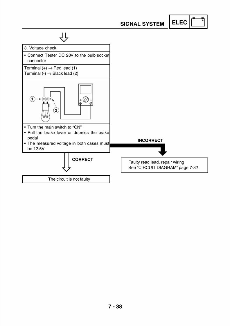
7/22/2019 Yamaha xt 125 service manual
http://slidepdf.com/reader/full/yamaha-xt-125-service-manual 264/279
7 - 38
– +ELEC
INCORRECT
Faulty read lead, repair wiring
See “CIRCUIT DIAGRAM” page 7-32
SIGNAL SYSTEM
CORRECT
3. Voltage check
• Connect Tester DC 20V to the bulb socketconnector
Terminal (+) → Red lead (1)
Terminal (-) → Black lead (2)
• Turn the main switch to “ON”
• Pull the brake lever or depress the brake
pedal
• The measured voltage in both cases must
be 12.5V
The circuit is not faulty

7/22/2019 Yamaha xt 125 service manual
http://slidepdf.com/reader/full/yamaha-xt-125-service-manual 265/279
7 - 39
– +ELEC
INCORRECT
Faulty flasher light switch → Replace the
left control unit
NO CONTINUITY
Replace bulb or bulb socket
SIGNAL SYSTEM
THE FLASHER LIGHTS AND/OR THE FLASHER
LIGHT PILOT LIGHTS FAIL TO COME ON
CORRECT
CONTINUITY
1. Bulb and bulb socket
• Check the bulb and bulb socket for continuity
2. Turn signal switch
• Disconnect nine-way connector of left hand
switch assembly (1)
• Connect Tester “Ω” to the leads
• Press the switch to activate the right turn
signal lights
Terminal (+) → Brown lead (2)
Terminal (-) → Green lead (4)
• Press the switch to activate the left turn
signal lights
Terminal (+) → Brown lead (2)
Terminal (-) → Purple lead (3)
• There must be continuity in both cases

7/22/2019 Yamaha xt 125 service manual
http://slidepdf.com/reader/full/yamaha-xt-125-service-manual 266/279
7 - 40
– +ELEC
INCORRECT
Faulty blue lead between main switch and
turn signal relay. Repair wiring
See “CIRCUIT DIAGRAM” page 7-32
NO CONTINUITY
Faulty brown lead between turn signal
relay and left hand switch. Repair wiring.
See “CIRCUIT DIAGRAM” page 7-32
SIGNAL SYSTEM
CONTINUITY
CORRECT
3. Turn signal relay voltage check
• Disconnect connector of turn signal relay (1)• Connect Tester DC 20V to the leads
Terminal (+) → Blue lead
Terminal (-) → Chassis ground lead
• Turn the main switch to “ON”
• The measured voltage must be 12V
4. Check the brown lead for continuity
• Disconnect connector of turn signal relay
• Disconnect connector of the left hand switch
• Connect Tester “Ω” to the terminals
• Check the brown lead for continuity
Faulty turn signal relay → Replace

7/22/2019 Yamaha xt 125 service manual
http://slidepdf.com/reader/full/yamaha-xt-125-service-manual 267/279
7 - 41
– +ELEC
INCORRECT
Faulty lead between the flasher light
switch and the bulb socket connector.
Repair wiring
See “CIRCUIT DIAGRAM” page 7-32
SIGNAL SYSTEM
CORRECT
5. Check voltage of right and left light holder
• Connect Tester DC 20V to the bulb socket
connector
(A) Left flasher lightTerminal (+) → Purple lead (1)
Terminal (-) → Chassis ground lead
(B) Right flasher light
Terminal (+) → Green lead (2)
Terminal (-) → Chassis ground lead
• Turn the main switch to “ON”
• (A) Use the switch to activate the left
flasher lights
• (B) Use the switch to activate the right
flasher lights
• The measured voltage in both cases must
be 12.5V
The circuit is not faulty

7/22/2019 Yamaha xt 125 service manual
http://slidepdf.com/reader/full/yamaha-xt-125-service-manual 268/279
7 - 42
– +ELEC
NO CONTINUITY
Faulty lead between neutral switch and
meter assembly connector. Repair wiring
See “CIRCUIT DIAGRAM” page 7-32
INCORRECT
Faulty neutral switch → Replace
SIGNAL SYSTEM
THE NEUTRAL SWITCH FAILS TO COME ON
CONTINUITY
CORRECT
1. Neutral switch check
• Connect Tester “Ω” and check the continuitybetween the neutral switch and the ground
Neutral switch (1) → Chassis ground (2)
Idle run → Continuity
Engaged gear → No continuity
2. Meter assembly check
• Disconnect connector of meter assembly (1)
• Disconnect cable terminal (2) of neutral
switch
• Connect Tester “Ω” as follows:
Terminal (+) → Blue lead cable terminal (2)
Terminal (-) → Red-black lead (3)
Replace the meter assembly
WARNING
After disassembling the cable terminal,
check that the neutral switch is tightened
properly.
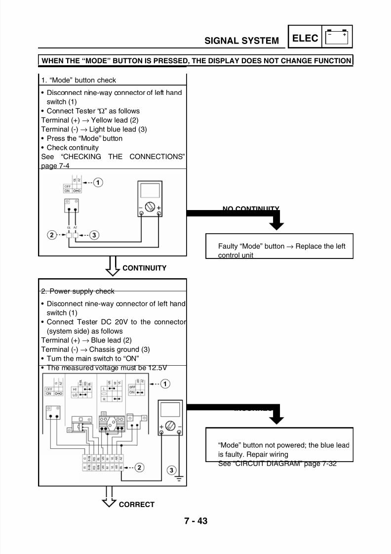
7/22/2019 Yamaha xt 125 service manual
http://slidepdf.com/reader/full/yamaha-xt-125-service-manual 269/279
7 - 43
– +ELEC
INCORRECT
“Mode” button not powered; the blue lead
is faulty. Repair wiring
See “CIRCUIT DIAGRAM” page 7-32
NO CONTINUITY
Faulty “Mode” button → Replace the left
control unit
SIGNAL SYSTEM
WHEN THE “MODE” BUTTON IS PRESSED, THE DISPLAY DOES NOT CHANGE FUNCTION
CONTINUITY
1. “Mode” button check
• Disconnect nine-way connector of left hand
switch (1)
• Connect Tester “Ω” as follows
Terminal (+) → Yellow lead (2)
Terminal (-) → Light blue lead (3)
• Press the “Mode” button
• Check continuity
See “CHECKING THE CONNECTIONS”
page 7-4
2. Power supply check
• Disconnect nine-way connector of left hand
switch (1)
• Connect Tester DC 20V to the connector
(system side) as follows
Terminal (+) → Blue lead (2)
Terminal (-) → Chassis ground (3)
• Turn the main switch to “ON”
• The measured voltage must be 12.5V
CORRECT

7/22/2019 Yamaha xt 125 service manual
http://slidepdf.com/reader/full/yamaha-xt-125-service-manual 270/279
7 - 44
– +ELEC
NO CONTINUITY
Faulty red lead. Repair wiring
See “CIRCUIT DIAGRAM” page 7-32
SIGNAL SYSTEM
CONTINUITY
3. Check the red lead for continuity
• Connect Tester “Ω
” as followsTerminal (+) → Red lead (3)
Terminal (-) → Red lead (4)
• Check the red lead for continuity between
left control unit connector (1) and meter
assembly connector (2)
Replace the meter assembly

7/22/2019 Yamaha xt 125 service manual
http://slidepdf.com/reader/full/yamaha-xt-125-service-manual 271/279
7 - 45
– +ELEC
NO CONTINUITY
Faulty white-green lead. Repair wiring
See “CIRCUIT DIAGRAM” page 7-32
PILOT LIGHT ON
Replace the fuel cock
SIGNAL SYSTEM
THE TACHOMETER IS FAULTY
THE FUEL LIGHT FAILS TO COME ON
CONTINUITY
• Connect Tester Ωx1 as follows
Terminal (+) → White-green lead (3)
Terminal (-) → White-green lead (4)• Check the white-green lead for continuity
between magneto flywheel connector (1)
and meter assembly connector (2)
Replace the meter assembly
PILOT LIGHT OFF
1. Fuel probe check
• Disconnect the connector of the fuel cock
• Create a jumper between the grey lead and
the black lead of the system side connector
• Turn the main switch to position “ON” and
wait for some seconds
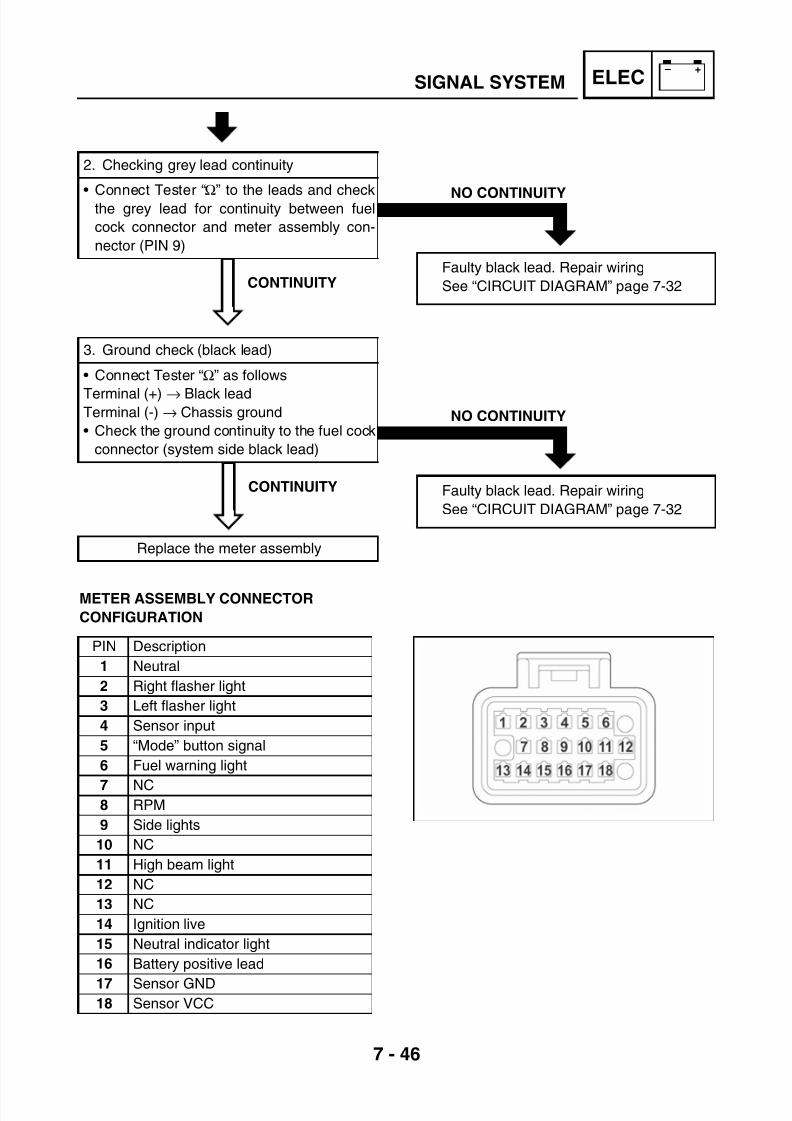
7/22/2019 Yamaha xt 125 service manual
http://slidepdf.com/reader/full/yamaha-xt-125-service-manual 272/279
7 - 46
– +ELEC
NO CONTINUITY
Faulty black lead. Repair wiring
See “CIRCUIT DIAGRAM” page 7-32
NO CONTINUITY
Faulty black lead. Repair wiring
See “CIRCUIT DIAGRAM” page 7-32
SIGNAL SYSTEM
CONTINUITY
CONTINUITY
METER ASSEMBLY CONNECTOR
CONFIGURATION
2. Checking grey lead continuity
• Connect Tester “Ω
” to the leads and checkthe grey lead for continuity between fuel
cock connector and meter assembly con-
nector (PIN 9)
3. Ground check (black lead)
• Connect Tester “Ω” as follows
Terminal (+) → Black leadTerminal (-) → Chassis ground
• Check the ground continuity to the fuel cock
connector (system side black lead)
Replace the meter assembly
PIN Description
1 Neutral
2 Right flasher light
3 Left flasher light
4 Sensor input
5 “Mode” button signal
6 Fuel warning light
7 NC8 RPM
9 Side lights
10 NC
11 High beam light
12 NC
13 NC
14 Ignition live
15 Neutral indicator light
16 Battery positive lead
17 Sensor GND18 Sensor VCC

7/22/2019 Yamaha xt 125 service manual
http://slidepdf.com/reader/full/yamaha-xt-125-service-manual 273/279
7 - 47
– +ELECCARBURETOR HEATER SYSTEM
CARBURETOR HEATER SYSTEMCIRCUIT DIAGRAM
(1) Main switch(2) Thermal sensor
(3) Carburetor heater

7/22/2019 Yamaha xt 125 service manual
http://slidepdf.com/reader/full/yamaha-xt-125-service-manual 274/279

7/22/2019 Yamaha xt 125 service manual
http://slidepdf.com/reader/full/yamaha-xt-125-service-manual 275/279
TRBLSHTG
CHAPTER 8
TROUBLESHOOTING
TROUBLESHOOTING.....................................................................................8-1ELECTRIC SYSTEM.................................................................................8-1COMPRESSION SYSTEM........................................................................8-2INTAKE AND EXHAUST SYSTEM ........................................................... 8-3
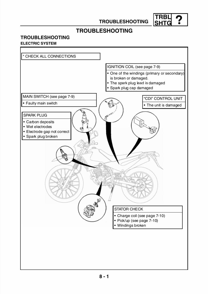
7/22/2019 Yamaha xt 125 service manual
http://slidepdf.com/reader/full/yamaha-xt-125-service-manual 276/279
8 - 1
TRBLSHTG
TROUBLESHOOTINGTROUBLESHOOTINGELECTRIC SYSTEM
MAIN SWITCH (see page 7-9)
• Faulty main switch
IGNITION COIL (see page 7-9)
• One of the windings (primary or secondary)
is broken or damaged.
• The spark plug lead is damaged
• Spark plug cap damaged
SPARK PLUG
• Carbon deposits
• Wet electrodes
• Electrode gap not correct
• Spark plug broken
“CDI” CONTROL UNIT
• The unit is damaged
STATOR CHECK
• Charge coil (see page 7-10)
• Pick/up (see page 7-10)
• Windings broken
TROUBLESHOOTING
* CHECK ALL CONNECTIONS

7/22/2019 Yamaha xt 125 service manual
http://slidepdf.com/reader/full/yamaha-xt-125-service-manual 277/279
8 - 2
TRBLSHTGTROUBLESHOOTING
COMPRESSION SYSTEM
WORN OUT/CARBON DEPOS-
ITS
WORN OUT/OVERHEATED/BROKEN
BROKEN
CARBON DEPOSITS
BROKEN
BROKEN
BROKEN
WORN OUT/OVERHEATED/
BROKENBROKEN
WORN OUT/SCRATCHED
WORN OUT/SCRATCHED/DAMAGED
WORN OUT/OVERHEATED/BROKEN
WORN OUT/DAMAGED/
BROKEN
INSUFFICIENT TIGHTENING TORQUE

7/22/2019 Yamaha xt 125 service manual
http://slidepdf.com/reader/full/yamaha-xt-125-service-manual 278/279
8 - 3
TRBLSHTGTROUBLESHOOTING
INTAKE AND EXHAUST SYSTEM
VACUUM HOSE
FUEL HOSE
• Clogged, bent or kinked
FUEL TANK CAP
• Clogged ventilation hole
IDLING SPEED
ADJUST SCREW• Improperly adjusted
(idling and starting)
“AIS” VALVE
• Faulty
VALVE TRAIN COMPONENTS
• Improper adjustment
• Improper timing
EXHAUST PIPE
• Holed or broken
• Carbon deposits
JET NEEDLE
• Improperly adjusted
(medium speed)
FLOAT VALVE
• Worn out
FLOAT
• Fuel level not correct
• Holed
FLOAT CHAMBER
• Accumulated dust and/or water
AIR FILTER
• Air intake
SILENCER
• Blocked• Broken
STARTER
• Improperly adjusted
(starting)
PILOT JET
• Clogged (low speed)
PILOT SCREW
• Improperly adjusted (idling
and starting)
MAIN JET
• Incorrect size
• Clogged (high speed)
(CARBURETOR)

7/22/2019 Yamaha xt 125 service manual
http://slidepdf.com/reader/full/yamaha-xt-125-service-manual 279/279