
Precision Digital PD683 PD688 PDF - Lesman Instrument Company
OneWireless
XYR 6000 Pressure Transmitter User's Manual
34-XY-25-15 R100
6/7/07
Release 100
ii OneWireless XYR 6000 Pressure Transmitter User's Manual R100 6/7/07
Notices and Trademarks
Copyright 2007 by Honeywell International Inc. Release 100 June 7, 2007
While this information is presented in good faith and believed to be accurate, Honeywell disclaims the implied warranties of merchantability and fitness for a particular purpose and makes no express warranties except as may be stated in its written agreement with and for its customers.
In no event is Honeywell liable to anyone for any indirect, special or consequential damages. The information and specifications in this document are subject to change without notice.
Honeywell, PlantScape, Experion PKS, and TotalPlant are registered trademarks of Honeywell International Inc.
Other brand or product names are trademarks of their respective owners.
Honeywell International
Process Solutions
2500 West Union Hills
Phoenix, AZ 85027
1-800 343-0228

R100 OneWireless XYR 6000 Pressure Transmitter User's Manual iii 6/7/07
About This Document This document describes preparation, operation and maintenance of the XYR 6000 Wireless Pressure Transmitters. Mounting, installation and wiring are covered in other documents.
Honeywell does not recommend using devices for critical control where there is a single point of failure or where single points of failure result in unsafe conditions. The initial release of OneWireless (R100) is targeted at open loop control, supervisory control, and controls that do not have environmental or safety consequences. As with any process control solution, the end-user must weigh the risks and benefits to determine if the products used are the right match for the application based on security, safety, and performance. Additionally, it is up to the end-user to ensure that the control strategy sheds to a safe operating condition if any crucial segment of the control solution fails.
Release Information
Document Name Document ID Release Number
Publication Date
XYR 6000 Pressure Transmitter User's Manual 34-XY-25-15 100 6/7/07
References The following list identifies all documents that may be sources of reference for material discussed in this publication.
Document Title
XYR 6000 Transmitters Quick Start Guide
Getting Started with Honeywell OneWireless Solutions
OneWireless Wireless Builder User’s Guide
OneWireless Builder Parameter Reference
Support and contact info
United States and Canada Contact: Honeywell Solution Support Center Phone: 1-800 822-7673. In Arizona: 602- 313-5558 Calls are answered by dispatcher between 6:00 am and 4:00 pm Mountain Standard Time.
Emergency calls outside normal working hours are received by an answering service and returned within one hour.
Facsimile: (602) 313-3293 Mail: Honeywell TAC, MS P13 2500 West Union Hills Drive Phoenix, AZ, 85027
iv OneWireless XYR 6000 Pressure Transmitter User's Manual R100 6/7/07
Europe Contact: Honeywell TAC-EMEA Phone: +32-2-728-2732 Facsimile: +32-2-728-2696 Mail: TAC-BE02 Hermes Plaza Hermeslaan, 1H B-1831 Diegem, Belgium
Pacific Contact: Honeywell Global TAC – Pacific Phone: 1300-300-4822 (toll free within Australia) +61-8-9362-9559 (outside Australia) Facsimile: +61-8-9362-9564 Mail: Honeywell Limited Australia 5 Kitchener Way Burswood 6100, Western Australia Email: [email protected]
India Contact: Honeywell Global TAC – India Phone: +91-20- 6603-9400 Facsimile: +91-20- 6603-9800 Mail: Honeywell Automation India Ltd. 56 and 57, Hadapsar Industrial Estate Hadapsar, Pune –411 013, India Email: [email protected]
Korea Contact: Honeywell Global TAC – Korea Phone: +82-2-799-6317 +82-11-9227-6324 Facsimile: +82-2-792-9015 Mail: Honeywell Co., Ltd 17F, Kikje Center B/D, 191, Hangangro-2Ga Yongsan-gu, Seoul, 140-702, Korea Email: [email protected]
People’s Republic of China Contact: Honeywell Global TAC – China Phone: +86- 21-5257-4568 Mail: Honeywell (China) Co., Ltd 33/F, Tower A, City Center, 100 Zunyi Rd. Shanghai 200051, People’s Republic of China Email: [email protected]

R100 OneWireless XYR 6000 Pressure Transmitter User's Manual v 6/7/07
Singapore Contact: Honeywell Global TAC – South East Asia Phone: +65-6580-3500 Facsimile: +65-6580-3501 +65-6445-3033 Mail: Honeywell Private Limited Honeywell Building 17, Changi Business Park Central 1 Singapore 486073 Email: [email protected]
Taiwan Contact: Honeywell Global TAC – Taiwan Phone: +886- 7- 536-2567 Facsimile: +886-7-536-2039 Mail: Honeywell Taiwan Ltd. 17F-1, No. 260, Jhongshan 2nd Road. Cianjhen District Kaohsiung, Taiwan, ROC Email: [email protected]
Japan Contact: Honeywell Global TAC – Japan Phone: +81-3-6730-7160 Facsimile: +81-3-6730-7228 Mail: Honeywell Japan Inc. New Pier Takeshiba, South Tower Building, 20th Floor, 1-16-1 Kaigan, Minato-ku, Tokyo 105-0022, Japan Email: [email protected]
World Wide Web Honeywell Solution Support Online:
http://www.honeywell.com/ps
Elsewhere Call your nearest Honeywell office.
Training Classes Honeywell Automation College:
http://www.automationcollege.com

vi OneWireless XYR 6000 Pressure Transmitter User's Manual R100 6/7/07
Symbol Definitions The following table lists those symbols used in this document to denote certain conditions.
Symbol Definition
ATTENTION: Identifies information that requires special consideration.
TIP: Identifies advice or hints for the user, often in terms of performing a task.
CAUTION
Indicates a situation which, if not avoided, may result in equipment or work (data) on the system being damaged or lost, or may result in the inability to properly operate the process.
CAUTION: Indicates a potentially hazardous situation which, if not avoided, may result in minor or moderate injury. It may also be used to alert against unsafe practices. CAUTION symbol on the equipment refers the user to the product manual for additional information. The symbol appears next to required information in the manual.
WARNING: Indicates a potentially hazardous situation, which, if not avoided, could result in serious injury or death. WARNING symbol on the equipment refers the user to the product manual for additional information. The symbol appears next to required information in the manual.
WARNING, Risk of electrical shock: Potential shock hazard where HAZARDOUS LIVE voltages greater than 30 Vrms, 42.4 Vpeak, or 60 VDC may be accessible.
ESD HAZARD: Danger of an electro-static discharge to which equipment may be sensitive. Observe precautions for handling electrostatic sensitive devices.
Protective Earth (PE) terminal: Provided for connection of the protective earth (green or green/yellow) supply system conductor.
Functional earth terminal: Used for non-safety purposes such as noise immunity improvement. NOTE: This connection shall be bonded to Protective Earth at the source of supply in accordance with national local electrical code requirements.
Earth Ground: Functional earth connection. NOTE: This connection shall be bonded to Protective Earth at the source of supply in accordance with national and local electrical code requirements.
Chassis Ground: Identifies a connection to the chassis or frame of the equipment shall be bonded to Protective Earth at the source of supply in accordance with national and local electrical code requirements.

R100 OneWireless XYR 6000 Pressure Transmitter User's Manual vii 6/7/07
Contents
1. INTRODUCTION.................................................................................................... 1 1.1 Purpose ..........................................................................................................................................1 1.2 Scope..............................................................................................................................................1 1.3 OneWireless network overview ...................................................................................................1 1.4 About the transmitter....................................................................................................................1
2. SPECIFICATIONS .................................................................................................3 2.1 Certifications and approvals........................................................................................................3
Transmitter .............................................................................................................................................................3 Authentication Device.............................................................................................................................................3
3. PREPARATION ..................................................................................................... 4 3.1 Installation .....................................................................................................................................4 3.2 Configuration.................................................................................................................................4 3.3 Connecting to network .................................................................................................................4 3.4 Calibrating the transmitter ...........................................................................................................4
Overview ................................................................................................................................................................4 Calibrate zero .........................................................................................................................................................4
4. FUNCTION BLOCKS............................................................................................. 6 4.1 Introduction ...................................................................................................................................6 4.2 Block description ..........................................................................................................................6
Block types .............................................................................................................................................................6 Block diagram.........................................................................................................................................................6
4.3 Parameter details ..........................................................................................................................7
5. OPERATION ..........................................................................................................8 5.1 Overview ........................................................................................................................................8
Display modes........................................................................................................................................................8 Authentication Device.............................................................................................................................................8
5.2 Transmitter PV display .................................................................................................................8 5.3 Transmitter quick view of parameters ......................................................................................12 5.4 Transmitter menu........................................................................................................................13
Menu tree .............................................................................................................................................................13 5.5 Authentication device menus ....................................................................................................14
Overview ..............................................................................................................................................................14 Main menu............................................................................................................................................................14 Security and Device Deployment .........................................................................................................................15
Contents
viii OneWireless XYR 6000 Pressure Transmitter User's Manual R100 6/7/07
Device Local Configuration .................................................................................................................................. 16 Read Device Information...................................................................................................................................... 17 Advanced Options................................................................................................................................................ 18
6. MAINTENANCE/REPAIR .................................................................................... 20 6.1 Introduction .................................................................................................................................20 6.2 Preventive maintenance .............................................................................................................20 6.3 Inspecting and cleaning barrier diaphragms ...........................................................................20
Tools required ...................................................................................................................................................... 20 Procedure ............................................................................................................................................................ 21 Torque ratings...................................................................................................................................................... 23
6.4 Replacing display/sensor module .............................................................................................24 Tools required ...................................................................................................................................................... 24 Procedure ............................................................................................................................................................ 24
6.5 Replacing batteries .....................................................................................................................26 When to replace................................................................................................................................................... 26 Tools required ...................................................................................................................................................... 26 Procedure ............................................................................................................................................................ 26
6.6 Replacing antenna ......................................................................................................................28 Tools required ...................................................................................................................................................... 28 Procedure ............................................................................................................................................................ 28
6.7 Parts .............................................................................................................................................31 6.8 Dimension drawings ...................................................................................................................34

Contents Tables
R100 OneWireless XYR 6000 Pressure Transmitter User's Manual ix 6/7/07
Tables Table 3-1 Calibrate zero ................................................................................................................................5 Table 5-1 PV engineering units .....................................................................................................................8 Table 5-2 PV status .......................................................................................................................................9 Table 5-3 Device status ...............................................................................................................................10 Table 5-4 Menu tree ....................................................................................................................................13 Table 5-5 Buttons for Device Local Configuration.......................................................................................16 Table 5-6 Advanced Options .......................................................................................................................19 Table 6-1 Inspecting and Cleaning Barrier Diaphragms .............................................................................21 Table 6-2 Process Head Bolt Torque Ratings.............................................................................................23 Table 6-3 Display/sensor module replacement ...........................................................................................24 Table 6-4 Battery replacement procedure ...................................................................................................26 Table 6-5 Antenna replacement procedure.................................................................................................29 Table 6-6 Parts (see Figure 12 and Figure 13) ..........................................................................................32 Table 6-7 Drawing numbers for DP models STDW924, STDW930, STDW974 .........................................34 Table 6-8 Drawing numbers for DHGP models STGW944, STGW974 ......................................................34
Contents Figures
x OneWireless XYR 6000 Pressure Transmitter User's Manual R100 6/7/07
Figures Figure 1 XYR 6000 Functional Diagram.......................................................................................................2 Figure 2 Block Diagram .................................................................................................................................6 Figure 3 Main menu.....................................................................................................................................14 Figure 4 Security and Device Deployment ..................................................................................................15 Figure 5 Device Local Configuration screen................................................................................................16 Figure 6 Read Device Information...............................................................................................................17 Figure 7 Advanced Options .........................................................................................................................18 Figure 8 Assembly of DP Transmitter Process Heads ................................................................................23 Figure 9 Display/sensor module removal and replacement ........................................................................25 Figure 10 Battery replacement ....................................................................................................................27 Figure 11 Antenna replacement ..................................................................................................................30 Figure 12 STDW924, STDW930, STDW974..............................................................................................31 Figure 13 STGW944, STGW974.................................................................................................................31

1. Introduction 1.1. Purpose
R100 OneWireless XYR 6000 Pressure Transmitter User's Manual 1 6/7/07
1. Introduction
1.1 Purpose This manual describes the Honeywell OneWireless XYR 6000 Pressure Transmitter function, operation and maintenance.
1.2 Scope The manual includes:
• Details of topics that relate uniquely to the Honeywell XYR 6000 Pressure Transmitter,
• This manual does not cover installation, mounting, or wiring. See XYR 6000 Transmitter Quick Start Guide (document 34-XY-25-15).
1.3 OneWireless network overview OneWireless is an all digital, serial, two-way communication mesh network that interconnects industrial field sensors to a central system.
OneWireless has defined standards to which field devices and operator stations communicate with one another. The communications protocol is built as an "open system" to allow all field devices and equipment that are built to OneWireless standard to be integrated into a system, regardless of the device manufacturer. This interoperability of devices using OneWireless technology is to become an industry standard for automation systems.
1.4 About the transmitter The XYR 6000 Pressure Transmitter is furnished with OneWireless interface to operate in a compatible distributed OneWireless system. The transmitter will interoperate with any OneWireless-registered device.
The transmitter includes OneWireless electronics for operating in a 2.4GHz network. It features function block architecture.
The XYR 6000 Pressure Transmitter comes in a variety of models for measurement applications involving one of these basic types of pressure:
• Differential pressure,
• Gauge pressure,
• Absolute pressure.
The transmitter measures the process pressure and transmits a digital output signal proportional to the measured variable. Its major components are an electronics housing and a meter body as shown in Figure 1 (a typical differential pressure model transmitter).
The XYR 6000 transmits its output in a digital OneWireless protocol format for direct digital communications with systems.
The Process Variable (PV) is available for monitoring and alarm purposes. Available PV update rates: 1, 5, 10, 30 seconds and are set on Wireless Builder. Slower update rates extend battery life. The meter body temperature is also available as a secondary variable for monitoring. Figure 1 shows a block diagram of the XYR 6000 Pressure transmitter’s operating functions.

1. Introduction 1.4. About the transmitter
2 OneWireless XYR 6000 Pressure Transmitter User's Manual R100 6/7/07
EEPROM
EEPROM
A/D
DP or APSensor
SPSensor
TempSensor
Multi-plexer
Electronics HousingMeter Body
RadioBoard
PressureInput
Micro-processor
Micro-processor
EEPROM
FactoryCharacterizationData
ConfigurationData
Battery
Antenna
MeasurementBoard
ConfigurationData
Figure 1 XYR 6000 Functional Diagram

2. Specifications 2.1. Certifications and approvals
R100 OneWireless XYR 6000 Pressure Transmitter User's Manual 3 6/7/07
2. Specifications
2.1 Certifications and approvals Transmitter
Approval / Item Ratings / Description
Nonincendive Nonincendive, CL I, Div 2, Groups A,B,C & D,
CL II & III, Div 2, Groups F & G, T4 Ta = 85°C
Non-Sparking CL I, Ex/AEx nC IIC T4; Ta = 85°C, Zone 2
Ex II 3 GD, EEx nA IIC T4; Ta = 85°C, Zone 2
Process Connections
Division 2 / Zone 2 apparatus may only be connected to processes classified as non-hazardous or Division 2 / Zone 2. Connection to hazardous (flammable or ignition capable) Division 1 / Zone 0, or 1 process is not permitted.
Enclosure Type Type 4X, IP 66/67
For detailed transmitter specifications see the following Specification and Model Selection Guides.
• XYR 6000 Wireless Transmitter Differential Pressure (document 34-XY-03-22)
• XYR 6000 Wireless Transmitter Absolute Pressure (document 34-XY-03-23)
• XYR 6000 Wireless Transmitter Gauge Pressure (document 34-XY-03-24)
Authentication Device Install the Authentication Device application on any PDA having
• Windows Mobile version 4.2+
• infrared port.

3. Preparation 3.1. Installation
4 OneWireless XYR 6000 Pressure Transmitter User's Manual R100 6/7/07
3. Preparation
3.1 Installation Refer to the XYR 6000 Transmitter Quick Start Guide (document 34-XY-25-21) for installation, mounting and wiring of your XYR 6000 transmitter.
3.2 Configuration The XYR 6000 Transmitter contains the electronics interface compatible for connecting to the OneWireless network. An operator uses the Wireless Builder application to configure blocks, to change operating parameters, and to create linkages between blocks that make up the transmitter’s configuration. These changes are written to the transmitter when it is authenticated by a security key.
3.3 Connecting to network Use Authentication Device to connect your transmitter to the OneWireless network. See page 15.
3.4 Calibrating the transmitter Overview
For all calibration methods, Wireless Builder must be used to unlock and take the channel out of service. Next, certain calibration commands can be issued from the transmitter’s calibration menu. Additional calibration commands are available in Wireless Builder.
Calibrate zero Calibrates the sensor to correct the input measurement due to fill fluid and transmitter position effects once the transmitter is installed and operating under process conditions.
ATTENTION
Setting user trim points will effectively override the calibration zero. Normally the calibration zero is only required if you do not intend to provide process-specific trim points.

3. Preparation 3.4. Calibrating the transmitter
R100 OneWireless XYR 6000 Pressure Transmitter User's Manual 5 6/7/07
Table 3-1 Calibrate zero
Step Action
1 Apply zero input pressure for your transmitter’s pressure type as follows.
Differential: With process pressure applied, connect HP and LP inputs together using the crossover valve on the 3-valve manifold or other equivalent method.
Gauge: Isolate the input pressure from the process and vent to the atmosphere.
Absolute: Due to the difficulty of applying absolute 0 psi, zero calibration of the AP transmitter is not recommended.
2 In Wireless Builder, set the transmitter’s channel to OOS (Out of Service).
3 In Wireless Builder, set the transmitter’s Write Lock to Unlocked.
4 At the transmitter, verify the PV value is followed by an out of service (OUT SVC) message.
Use Authentication Device’s Device Local Configuration buttons to navigate to the transmitter’s CAL menu.
If CAL menu is passcode protected, enter the passcode.
If the channel is not out of service a WRONG MODE message will be displayed. Go to step 2.
If the transmitter is locked a LOCKED message will be displayed. Go to step 3.
5 Select CAL ZERO. With CAL ZERO displayed, press Enter to set the current applied pressure to zero. If successful the display will briefly show “ZERO SET”. If unsuccessful the display will briefly show “ERROR”.
6 Exit the menu.
7 Reverse step 1.
8 When ready, in Wireless Builder return the transmitter’s channel to service and set Write Lock to Locked.

4. Function blocks 4.1. Introduction
6 OneWireless XYR 6000 Pressure Transmitter User's Manual R100 6/7/07
4. Function blocks
4.1 Introduction This section explains the construction and contents of the XYR 6000 Pressure Transmitter Function Blocks.
4.2 Block description Block types
Blocks are the key elements that make up the transmitter’s configuration. The blocks contain data (block objects and parameters) which define the application, such as the inputs and outputs, signal processing and connections to other applications. The XYR 6000 Transmitter contains the following block types.
Block Type Function
Device Contains parameters related to the overall field device rather than a specific input or output channel within it. A field device has exactly one device block.
AITB Contains parameters related to a specific process input or output channel in a measurement or actuation device. An AITB defines a measurement sensor channel for an analog process variable represented by a floating-point value. There is one AITB per sensor.
Radio Contains parameters related to radio communication between the transmitter and the multimode(s).
Block diagram Figure 2 shows the blocks of the XYR 6000 Transmitter.
Sensor Analog Input Transducer Block (AITB)
Transmitter
Device Block
Communication Stack
Algorithm OUT
Read/Write
Publish Read/Write
Sensor Analog Input Transducer Block (AITB)
Transmitter
Device Block
Communication Stack
Algorithm OUT
Read/Write
Publish Read/Write
Figure 2 Block Diagram
Each of these blocks contains parameters that are standard WNSIA-transmitter defined parameters. The AITB and device blocks contain standard parameters common to all XYR 6000 transmitter models (that is, pressure, temperature, corrosion, HLAI) as well as pressure-specific parameters. The radio block contains parameters for communication with the wireless network.

4. Function blocks 4.3. Parameter details
R100 OneWireless XYR 6000 Pressure Transmitter User's Manual 7 6/7/07
4.3 Parameter details The transmitter itself displays a few basic parameters, such as tag, serial number, device revision, build, device address, WF ID.
For more information on parameters, refer to the following documents.
• OneWireless Wireless Builder User’s Guide
• OneWireless Builder Parameter Reference

5. Operation 5.1. Overview
8 OneWireless XYR 6000 Pressure Transmitter User's Manual R100 6/7/07
5. Operation
5.1 Overview Display modes
The transmitter has the following display modes.
• Test. Appears briefly after power-up to self-test the display.
• PV display. Default mode of the transmitter displays the PV and any status messages. See below.
• Quick view of parameters. Displays read-only parameters then returns to PV display. See page 12.
• Menu. Displays the menu. See page 13.
Authentication Device To navigate the transmitter displays and menus, hold the Authentication Device no more than 6” from the transmitter and aim the infrared beam at the transmitter display while tapping the Device Local Configuration buttons (Table 5-5).
5.2 Transmitter PV display In PV display, the following information is displayed in sequence.
Item displayed Example Details
PV value +14.7 Latest PV value.
PV engineering units PSI See Table 5-1.
PV status BAD See Table 5-2. If PV status is not displayed then the PV value is good.
Device status LOW BATT See Table 5-3. If device status is not displayed then the device status is normal.
If two or more device status messages are in effect they are displayed alternating with the PV.
Table 5-1 PV engineering units
Engineering units Description
MPa milliPascals
kPa kilopascals
bar Bars
mbar Millibars
PSI Pounds per square inch
G/CM2 Grams per square centimeter

5. Operation 5.2. Transmitter PV display
R100 OneWireless XYR 6000 Pressure Transmitter User's Manual 9 6/7/07
Engineering units Description
KG/CM2 Kilograms per square centimeter
INH2O 4C Inches of water at 4° C
INH2O 68F Inches of water at 68°F
MMH2O 4C Millimeters of water at 4°C
MMH2O 68F Millimeters of water at 68° F
INHG 0C Inches of mercury at 0° C
MMHG 0C Millimeters of mercury at 0° C
PERCENT Percent
Table 5-2 PV status
PV status Cause - Action
(blank) • PV is normal – no action required
BAD • Possible calibration error – Clear calibration
• AITB can not execute due to internal firmware state – Attempt cold restart of device.
• AITB can not execute due to hardware fault – Replace sensor board
• Sensor failure – Check Connection between Sensor board and Meter Body.
• Meter Body Characterization Data is Bad – Replace Meter Body
• Meter Body A/D Failure – Replace Meter Body
• Meter Body Sensor Fail – Replace Meter Body
BAD CONFIG • Configuration is bad – Check possible units and range settings for input type and correct AITB configuration.
BAD E FAIL • Hardware fault detected - Replace sensor board
OUTSVC • AITB mode is out of service – Restore mode to Auto in Wireless Builder
UNC • Warning: Input inaccurate due to uncertain input data integrity.
• Warning: Input inaccurate due to input conversion limitations or resolution.
• Warning: Input outside of characterized range. Value is estimated.

5. Operation 5.2. Transmitter PV display
10 OneWireless XYR 6000 Pressure Transmitter User's Manual R100 6/7/07
Table 5-3 Device status
Status Root Status Bit Definition What to do
E FAIL DEV_ST_ELEC_FAIL Electrical Failure detected on Sensor Board. Could be caused by one of the status items marked by *.
Replace sensor board
IP ERR DEV_ST_INPUT_FAIL Input Error Possible meter body sensor failure.
LOW BAT DEV_ST_LOW_BAT Batter Voltage Critically Low
Replace batteries as soon as possible.
CFG ERR DEV_ST_CONF_ERR Configuration Check Error.
Database is corrupted. Cold start and reload configuration.
CAL ERR DEV_ST_CAL_ERR Calibration Data Invalid or could not be read. For pressure devices check sensor connection to meter body.
Use Cal Clear, Restore, or User Calibrate.
NO RADIO DEV_ST_RADIO_ERR Radio Board is not accessible.
Check radio board installed. Replace radio board.
HEAP ERR* DEV_ST_HEAP_ERR Heap Allocation Failure. Software detected heap shortage and some communication packets may have been dropped.
Clear by warm restart of device. If condition persists contact Honeywell service.
FW ERR* DEV_ST_DEV_FW_ERR Sensor Board Firmware Error. The software did not pass verification tests.
Contact Honeywell service for replacement module.
WDT ERR* DEV_ST_WDT_ERR Sensor Watch Dog Timeout. The processor was restarted due to unexpected operation.
Clear by warm restart of device. If condition persists contact Honeywell service.
ROM ERR* DEV_ST_ROM_FAULT Startup diagnostics detected defect in Sensor Read Only Memory
Replace sensor module.
RAM ERR* DEV_ST_RAM_FAULT Startup diagnostics detected defect in Processor Random Access Memory
Replace sensor module.
NVM ERR* DEV_ST_NVM_FAULT Startup diagnostics detected defect in Sensor Non-Volatile Memory
Replace sensor module.
AD ERR* DEV_ST_AD_FAULT Diagnostics detected defect with Analog to Digital Converter.
Check connection between meter body and sensor module. Replace meter body is conditions persists.

5. Operation 5.2. Transmitter PV display
R100 OneWireless XYR 6000 Pressure Transmitter User's Manual 11 6/7/07
Status Root Status Bit Definition What to do
CHAR ERR DEV_ST_CHAR_FAULT Startup Diagnostics detected error in Meter Body Characterization Data
Check connection between meter body and sensor module. Replace meter body is conditions persists.
OVR TEMP DEV_ST_SENS_OVT Meter Body detected over temperature.
The meter body is being subjected to temperatures above the specified operational range. Correct over temperature condition
OVR LOAD DEV_ST_MB_OVL Meter Body detected Pressure Overload
The meter body is being subjected to pressure above the specified operational range. Correct Over pressure condition
BAD RADIO SPI
radio diag status Bit 0 Radio detected loss of communication with sensor board over the inter-processor communication link.
The sensor module or radio board is not functioning properly. Reset both the radio and sensor module. If condition persists contact Honeywell service.
BAD RADIO EEPROM
radio diag status Bit 1 Radio EEPROM SPI Communication failure
The radio will not be able to perform firmware upgrades but will operate normally using installed code. Replace radio board.
RADIO WDT RESET
radio diag status Bit 2 Radio Watch Dog Timeout detected
The radio firmware is not operating normally. Restart radio board. If condition persists install new firmware or replace radio module.
BAD RADIO FHSS
radio diag status Bit 3 Radio Frequency Hopping Spread Spectrum Radio circuitry failure
The radio processor detected error on internal radio circuitry. Replace radio board.

5. Operation 5.3. Transmitter quick view of parameters
12 OneWireless XYR 6000 Pressure Transmitter User's Manual R100 6/7/07
5.3 Transmitter quick view of parameters If you press the up or down arrow key during the PV display, the following quick view parameters are shown sequentially, then the PV display resumes.
Parameter Description
Transmitter type HONEYWELL XYR 6000 PRESSURE
Tag The name given to this transmitter
Serial number Transmitter serial number
Device revision This parameter changes whenever objects and parameters are added, deleted, or the data type or range changes. It does not change if the application firmware changes without affecting the device description.
Build Sensor firmware number
MB Serial number Meter body serial number

5. Operation 5.4. Transmitter menu
R100 OneWireless XYR 6000 Pressure Transmitter User's Manual 13 6/7/07
5.4 Transmitter menu Menu tree
At the PV display, press Enter to access the menus. To interact with the menus use the Device Local Configuration. See page 16.
Table 5-4 Menu tree
Menu item Description
CAL Calibration menu. May be password-protected. See Table 5-5 on page 16 for password number entry.
CAL ZERO Calibrate zero. See page 4.
RADIO Radio menu
PRI RSSI Primary receive signal strength. Read only. Signal strength 00 is too weak to connect to the network.
Displayed Value Value dBm Rx Margin dB
00 < -86 < 10
01 -86 to -81 10 to 15
02 -80 to -75 16 to 21
03 -74 to -69 22 to 27
04 -68 to -63 28 to 33
05 -62 to -57 34 to 39
06 -56 to -51 40 to 45
07 -50 to -45 46 to 51
08 -44 to -11 52 to 85
09 ≥ -10 Saturation
SEC RSSI Secondary receive signal strength. Same as PRI RSSI. Read only.
NWK STAT Network status. Read only.
CONNECTED means the transmitter radio and a multinode have detected each other. It does not necessarily mean security has been enabled or that the Wireless Builder has sensed the transmitter.
NOT CONNECTED means radio communcations with a multinode have not been established, or signal strength is too weak.
WFN ID Wireless Field Network ID. Read only.
DEV ADD Device address. Read only.
TX POWER Radio transmit power. Read only.

5. Operation 5.5. Authentication device menus
14 OneWireless XYR 6000 Pressure Transmitter User's Manual R100 6/7/07
5.5 Authentication device menus Overview
Hold the Authentication Device no more than 6” from the transmitter and aim the infrared beam at the transmitter display while tapping on the screen command or button.
Main menu The main menu is shown below.
Figure 3 Main menu
5. Operation 5.5. Authentication device menus
R100 OneWireless XYR 6000 Pressure Transmitter User's Manual 15 6/7/07
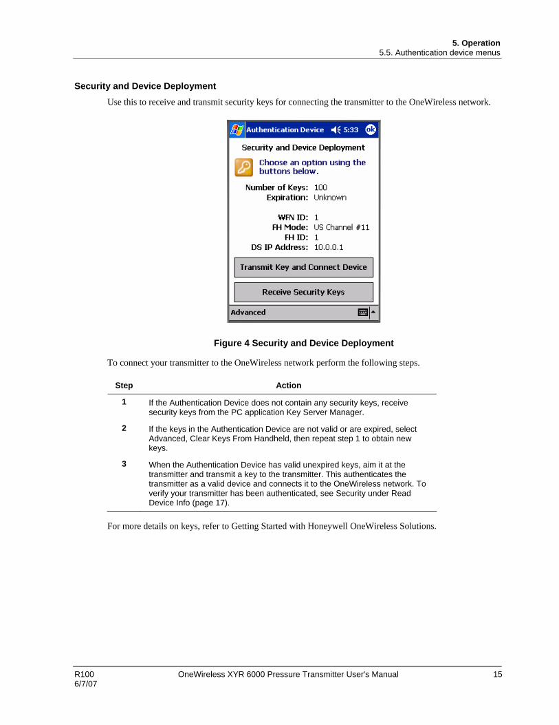
Security and Device Deployment Use this to receive and transmit security keys for connecting the transmitter to the OneWireless network.
Figure 4 Security and Device Deployment
To connect your transmitter to the OneWireless network perform the following steps.
Step Action
1 If the Authentication Device does not contain any security keys, receive security keys from the PC application Key Server Manager.
2 If the keys in the Authentication Device are not valid or are expired, select Advanced, Clear Keys From Handheld, then repeat step 1 to obtain new keys.
3 When the Authentication Device has valid unexpired keys, aim it at the transmitter and transmit a key to the transmitter. This authenticates the transmitter as a valid device and connects it to the OneWireless network. To verify your transmitter has been authenticated, see Security under Read Device Info (page 17).
For more details on keys, refer to Getting Started with Honeywell OneWireless Solutions.

5. Operation 5.5. Authentication device menus
16 OneWireless XYR 6000 Pressure Transmitter User's Manual R100 6/7/07
Device Local Configuration Use Device Local Configuration buttons (Table 5-5) to navigate the transmitter menus (Table 5-4) and to make selections and changes.
Figure 5 Device Local Configuration screen
Table 5-5 Buttons for Device Local Configuration
Button Function
• Enter the Menu Tree.
• Enter submenu of the menu that is appearing on the screen.
• Execute action.
• Submit the entered number while doing number entry.
• Read value of certain displayed parameters.
• Go to the next menu in the same level.
• View quick view parameters in Normal Display Sequence (PV Display).
• During number entry, increment the digit or change +/- sign.
• Go to the previous menu in the same level.
• View quick view parameters in Normal Display Sequence (PV Display).
• During number entry, decrement the digit or change +/- sign.
• Go to the upper menu level.
• When changing a number value, move cursor to the left/more significant digit, then wrap around to the least significant digit.

5. Operation 5.5. Authentication device menus
R100 OneWireless XYR 6000 Pressure Transmitter User's Manual 17 6/7/07
Read Device Information Use this to read the device information shown in Figure 6. Similar to quick view parameters on the transmitter display. (See page 12.)
Figure 6 Read Device Information
Item Description
Tag The name given to this transmitter
Serial Transmitter serial number
DevAddr Device Address in hexadecimal.
DevRev Device Revision. This parameter changes whenever objects and parameters are added, deleted, or their data type or range changes. It does not change if the application firmware changes withount affecting the device description. Range: 0 to 65535.
Build Sensor and radio firmware build numbers.
WFN ID Wireless Field Network ID. Range: 0 to 255.
FH Mode Frequency group or frequency channel selection used by the wireless network of the device. The value must match the value set in the gateway and interface nodes to allow communication between the device and the wireless network.
Modes:
US Channel number 1
US Channel number 6
US Channel number 11

5. Operation 5.5. Authentication device menus
18 OneWireless XYR 6000 Pressure Transmitter User's Manual R100 6/7/07
Item Description
Guard bands outside US Channel number 1, 6 and 11
EU Channel number 1
EU Channel number 7
EU Channel number 13
Guard bands outside EU Channels 1, 7 and 13
FH ID Frequency hopping pattern used by the wireless network of the device. The value must match the value set in the gateway and interface nodes to allow communication between the device and the wireless network. Range: 0 to 255
Security Security Disabled - the transmitter has not been authenticated with a security key.
Security Establishing - a security key has been sent to the transmitter and the transmitter is waiting for authentication by a multinode.
Security Enabled - the transmitter has been authenticated and is connected to the OneWireless network.
Advanced Options Advanced options are non-typical configuration commands.
Figure 7 Advanced Options

5. Operation 5.5. Authentication device menus
R100 OneWireless XYR 6000 Pressure Transmitter User's Manual 19 6/7/07
Table 5-6 Advanced Options
Item Description
Restart To Defaults Commands the transmitter to restart to factory default configuration. Network and security configurations will be cleared.
Restart Commands the transmitter to restart with the current configuration.
Read TX Power Level Reads the transmission power level of the transmitter radio.
Read Tracelog Flag Not available for transmitters. Used with multinodes. Reads conditional tracelog flag value. Tracelog flags are used to enable and disable logging functionality used for field support by development engineering.
Write Tracelog Flag Not available for transmitters. Used with multinodes. Writes conditional tracelog flag value. Tracelog flags are used to enable and disable logging functionality used for field support by development engineering.
Select Infrared Communication Port
Overrides the detected infrared communication port detected on your PDA. If infrared communication is not functioning, you can override the detected settings using this option.

6. Maintenance/Repair 6.1. Introduction
20 OneWireless XYR 6000 Pressure Transmitter User's Manual R100 6/7/07
6. Maintenance/Repair
6.1 Introduction This section provides information about preventive maintenance routines and replacing damaged parts. The topics covered in this section are:
Preventive maintenance of the meter body barrier diaphragms and process piping to the transmitter.
Replacement of damaged parts such as the transmitter PWA and meter body.
6.2 Preventive maintenance TheXYR 6000 transmitter itself does not require any specific maintenance routine at regularly scheduled intervals. However, you should consider carrying out these typical inspection and maintenance routines on a schedule that is dictated by the characteristics of the process medium being measured and whether blow-down facilities or purge systems are being used.
Check piping for leaks.
Clear the piping of sediment or other foreign matter.
Clean the transmitter’s pressure chambers including the barrier diaphragms.
6.3 Inspecting and cleaning barrier diaphragms Depending on the characteristics of the process medium being measured, sediment or other foreign particles may collect in the process head cavity/chamber and cause faulty measurement. In addition, the barrier diaphragm or diaphragms in the transmitter’s meter body may become coated with a residue from the process medium. The latter is also true for external diaphragms on flange mount and remote seal type transmitters.
In most cases, you can readily remove the process head or heads from the transmitter’s meter body to clean the process head cavity and inspect the barrier diaphragm or diaphragms. For flange mount and remote seal diaphragms, you may only need to run a purge line in the tank to rinse off the face of the diaphragm.
The procedure in Table 6-1 outlines the general steps for inspecting and cleaning barrier diaphragms. You may have to modify the steps to meet your particular process or transmitter model requirements. Figure 8 shows an exploded view of a DP transmitter’s meter body for reference.
WARNING
Risk of death or serious injury by explosion. Do not open transmitter enclosure when an explosive gas atmosphere is present.
Tools required
• 5/8” Wrench or Socket for 7/16” Dia. Hex Bolt
• 3/4” Wrench or Socket for 7/16” Hex Nut
• Calibrated torque wrench. For the most accurate performance, select a torque wrench that has a maximum torque value near the middle of the tool’s torque range. For example, if applying 68 N-M (50 Lb-Ft), select a torque wrench with range of 7 N-M to 136 N-M (5 to 100 Lb-Ft).

6. Maintenance/Repair 6.3. Inspecting and cleaning barrier diaphragms
R100 OneWireless XYR 6000 Pressure Transmitter User's Manual 21 6/7/07
Procedure
Table 6-1 Inspecting and Cleaning Barrier Diaphragms
Step Action
1 Close all valves and isolate transmitter from process. Open vent in process head to drain fluid from transmitter’s meter body, if required.
ATTENTION
We recommend that you remove the transmitter from service and move it to a clean area before taking it apart.
WARNING
Risk of death or serious injury by explosion. Do not open transmitter enclosure when an explosive gas atmosphere is present.
2 Remove nuts from bolts that hold process head or heads to meter body. Remove process heads and bolts. See Figure 8.
3 Remove gasket and clean interior of process head using soft bristle brush and suitable solvent.
CAUTION
Diaphragm surface is fragile. Be very gentle, do not damage.
4 Inspect barrier diaphragm for any signs of deterioration or corrosion. Look for possible residue and clean if necessary.
If diaphragm is dented, has distorted convolutions or radial wrinkles, performance may be affected. Contact Honeywell for assistance.
5 Replace gasket.
ATTENTION
• We recommend that you install a new gasket whenever a process head is removed for cleaning.

6. Maintenance/Repair 6.3. Inspecting and cleaning barrier diaphragms
22 OneWireless XYR 6000 Pressure Transmitter User's Manual R100 6/7/07
Step Action
Larger gasket groove for lower pressure applications
Smaller gasket groove for high pressure applications
22518
Larger gasket groove for lower pressure applications
Smaller gasket groove for high pressure applications
22518 GP/AP Process Head
• For process heads of a GP or AP transmitter with dual-head design, see illustration for differential pressure transmitters in Figure 8.
6 Coat threads on process head bolts with anti-seize compound such as “Neverseize” or equivalent.
7 Replace process head or heads and bolts. Finger tighten nuts.
8 Use a torque wrench to gradually tighten nuts to torque rating shown in Table 6-2, in sequence shown in Figure 8. Tighten head bolts in stages of 1/3 full torque, 2/3 full torque, and then full torque.
9 Return transmitter to service.

6. Maintenance/Repair 6.3. Inspecting and cleaning barrier diaphragms
R100 OneWireless XYR 6000 Pressure Transmitter User's Manual 23 6/7/07
1
2
3
4
Tighten in sequence shown
Figure 8 Assembly of DP Transmitter Process Heads
Torque ratings Table 6-2 lists process head bolt torque ratings for given transmitter type.
Table 6-2 Process Head Bolt Torque Ratings
Bolt Type 7/16 x 14 UNC
Meterbody Type 51452557-001 (Carbon Steel - standard; no option specified)
51452557-002 and –003 (NACE [“CR” option], Non-NACE [“SS” option] 316 Stainless Steel)
51452557-004 (B7M Alloy Steel [“B7” option])
50019775XXXX 67,8 N•M +/- 3,4 N•M (50.0 Lb-Ft +/- 2.5 Lb-Ft)
56,9 N•M +/- 2,8 N•M (42.0 Lb-Ft +/- 2.1 Lb-Ft)
48,8 N•M +/- 2,4 N•M (36.0 Lb-Ft +/- 1.8 Lb-Ft)

6. Maintenance/Repair 6.4. Replacing display/sensor module
24 OneWireless XYR 6000 Pressure Transmitter User's Manual R100 6/7/07
6.4 Replacing display/sensor module Tools required
• #1 Phillips Screwdriver or 1/8” Slotted Screwdriver
• Torque Screwdriver
• 1.5 mm hex key
Procedure
WARNING
Risk of death or serious injury by explosion. Do not open transmitter enclosure when an explosive gas atmosphere is present.
CAUTION
Take precautions against electrostatic discharge to prevent damaging the display/sensor module.
Table 6-3 Display/sensor module replacement
Step Action
1 Honeywell recommends that the transmitter be removed from service and moved to a clean area before servicing.
2 Loosen the M3 locking set screw on the display end-cap. See item 1 in Figure 9. Unscrew and remove the end cap.
3 Loosen the two screws on the display/sensor module. See items 2 in Figure 9.
4 Disconnect each connector on the display/sensor module. See items 3 in Figure 9.
5 Install new sensor module. Be sure to orient display/sensor module in the proper viewing orientation before tightening two sensor compartment screws.
Reverse steps 1-4.
Torque screws to 0,4 – 0,6 N-M (3.5 – 5.3 Lb-in).
Honeywell recommends lubricating the end cap O-ring with a Silicon Grease such as Dow Corning #33 or equivalent before replacing the end cap.
Return transmitter to service.

6. Maintenance/Repair 6.4. Replacing display/sensor module
R100 OneWireless XYR 6000 Pressure Transmitter User's Manual 25 6/7/07
1
2
23
3
Figure 9 Display/sensor module removal and replacement

6. Maintenance/Repair 6.5. Replacing batteries
26 OneWireless XYR 6000 Pressure Transmitter User's Manual R100 6/7/07
6.5 Replacing batteries When to replace
When the transmitter displays a LO BATT message you have 2-4 weeks to replace both batteries before they expire. When batteries are removed or expired, all transmitter data is retained in the transmitter’s non-volatile memory.
Tools required • #1 Phillips Screwdriver or 1/8” Slotted Screwdriver
• Torque Screwdriver
• 1.5 mm hex key
Procedure
ATTENTION
Batteries must be replaced only by a trained service technician.
WARNINGS
• Risk of death or serious injury by explosion. Do not open transmitter enclosure when an explosive gas atmosphere is present.
• The battery used in this device may present a risk of fire or chemical burn if mistreated. Do not recharge, disassemble, heat above 100°C (212°F), or incinerate.
Table 6-4 Battery replacement procedure
Step Action
ATTENTION
You must replace both batteries. Both batteries must be the same model from the same manufacturer. Mixing old and new batteries or different manufacturers is not permitted.
Use only the following 3.6V lithium thionyl chloride (Li-SOCl2) batteries (non-rechargeable), size D. No other batteries are approved for use in XYR 6000 Wireless Transmitters.
• Xeno Energy XL-205F
• Eagle Picher PT-2300H
• Tadiran TL-5930/s
• Honeywell p/n 50026010-001 (Two 3.6V lithium thionyl chloride batteries)
• Honeywell p/n 50026010-002 (Four 3.6V lithium thionyl chloride batteries)
• Honeywell p/n 50026010-003 (Ten 3.6V lithium thionyl chloride batteries)
1 Loosen the M3 locking set screw on the battery end-cap (opposite end from display). See item 1 in Figure 10. Unscrew and remove the end cap.
2 Using thumb and forefinger, squeeze the battery connector at top and bottom to disengage the locking mechanism, then pull to disconnect. See item 2 in Figure 10.

6. Maintenance/Repair 6.5. Replacing batteries
R100 OneWireless XYR 6000 Pressure Transmitter User's Manual 27 6/7/07
Step Action
3 Loosen the two battery holder retaining screws (closest to the batteries). See item 3 in Figure 10. The screws are captive.
4 Pull the battery holder out of the transmitter.
5 Remove the old batteries from the battery holder. If needed, pry out the batteries by using a slotted screwdriver as a lever in the holder’s side slots. See item 4 in Figure 10.
6 Insert the new batteries using correct polarity shown on the battery holder.
7 Insert the battery holder into the transmitter. Reattach the screws and tighten to 0,4 – 0,6 N-M (3.5 – 5.3 Lb-in).
Re-connect battery connector.
Honeywell recommends lubricating the end cap O-ring with a Silicon Grease such as Dow Corning #33 or equivalent before replacing the end cap.
8 Screw the end cap back on and tighten the M3 locking screw.
9 Dispose of used battery promptly per local regulations or the battery manufacturer’s recommendations. Keep away from children. Do not disassemble and do not dispose of in fire.
1
2
+-
+- 3
4
Figure 10 Battery replacement

6. Maintenance/Repair 6.6. Replacing antenna
28 OneWireless XYR 6000 Pressure Transmitter User's Manual R100 6/7/07
6.6 Replacing antenna Tools required
• #1 Phillips Screwdriver or 1/8” Slotted Screwdriver
• Torque Screwdriver
• 1.5 mm hex key
Procedure
ATTENTION
You must replace your antenna with the same type, that is, elbow, straight, or remote. Changing to a different antenna type is not permitted by approval agencies.
CAUTION
Take precautions against electrostatic discharge to prevent damaging the display/sensor module.
WARNING
POTENTIAL ELECTROSTATIC CHARGING HAZARD
The integrally mounted antenna shroud is made of Teflon® and has a surface resistance greater than 1Gohm per square. When the XYR 6000 transmitter is installed in potentially hazardous locations care should be taken not to electrostatically charge the surface of the antenna shroud by rubbing the surface with a cloth, or cleaning the surface with a solvent. If electrostatically charged, discharge of the antenna shroud to a person or a tool could possibly ignite a surrounding hazardous atmosphere.

6. Maintenance/Repair 6.6. Replacing antenna
R100 OneWireless XYR 6000 Pressure Transmitter User's Manual 29 6/7/07
Table 6-5 Antenna replacement procedure
Step Action
1 Honeywell recommends that the transmitter be removed from service and moved to a clean area before servicing.
2 Loosen the M3 locking set screw on the display end-cap. See item 1 in Figure 11. Unscrew and remove the front end cap.
3 Loosen the two screws on the display/sensor module. See items 2 in Figure 11.
4 Remove the display/sensor module from the transmitter body and disconnect the antenna connector from CN2 connector on the display/sensor module. See item 3 in Figure 11.
5 Loosen the locking set screw at the antenna base. Unscrew the antenna from the transmitter. Remove the antenna and its connector from the transmitter. See Figure 11.
6 Feed the new antenna’s connector through the antenna hole to the front of the transmitter. Do not connect to display/sensor module yet. Screw new antenna into transmitter body until finger-tight, then back off 180 degrees to permit adjustment later.
7 Attach antenna connector to CN2 connector on display/sensor module. See item 3 in Figure 11.
8 Insert display/sensor module. Orient in the proper viewing orientation before tightening two sensor compartment screws. See items 2 in Figure 11. Torque screws to 0,4 – 0,6 N-M (3.5 – 5.3 Lb-in).
9 Replace the front end cap. Honeywell recommends lubricating the front end cap O-ring with a Silicon Grease such as Dow Corning #33 or equivalent before replacing the end cap.
10 Adjust antenna for best reception. Don’t rotate antenna more than 180 degrees either direction or you could twist and break the antenna wiring inside. Tighten the antenna locking set screw.

6. Maintenance/Repair 6.6. Replacing antenna
30 OneWireless XYR 6000 Pressure Transmitter User's Manual R100 6/7/07
Antenna connector
1
2
23
Figure 11 Antenna replacement

6. Maintenance/Repair 6.7. Parts
R100 OneWireless XYR 6000 Pressure Transmitter User's Manual 31 6/7/07
6.7 Parts Use the following figures and table to find replacement parts.
Figure 12 STDW924, STDW930, STDW974
Figure 13 STGW944, STGW974
6. Maintenance/Repair 6.7. Parts
32 OneWireless XYR 6000 Pressure Transmitter User's Manual R100 6/7/07
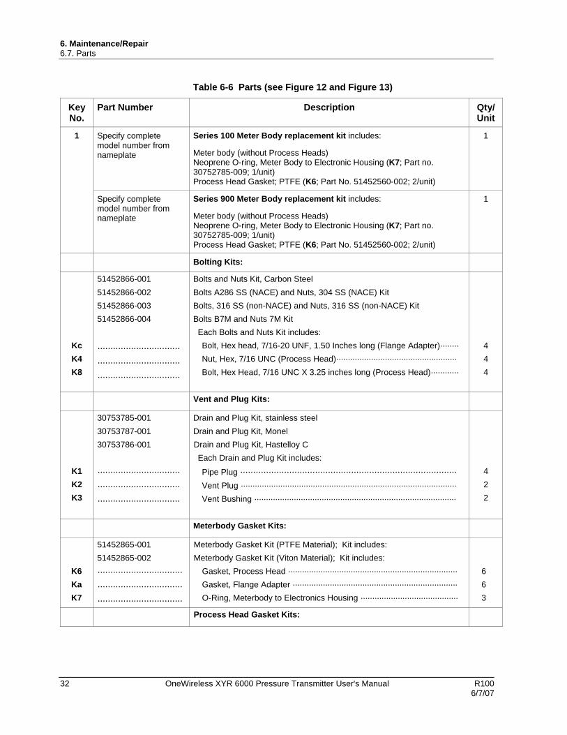
Table 6-6 Parts (see Figure 12 and Figure 13)
Key No.
Part Number Description Qty/ Unit
1 Specify complete model number from nameplate
Series 100 Meter Body replacement kit includes:
Meter body (without Process Heads) Neoprene O-ring, Meter Body to Electronic Housing (K7; Part no. 30752785-009; 1/unit) Process Head Gasket; PTFE (K6; Part No. 51452560-002; 2/unit)
1
Specify complete model number from nameplate
Series 900 Meter Body replacement kit includes:
Meter body (without Process Heads) Neoprene O-ring, Meter Body to Electronic Housing (K7; Part no. 30752785-009; 1/unit) Process Head Gasket; PTFE (K6; Part No. 51452560-002; 2/unit)
1
Bolting Kits:
Kc K4 K8
51452866-001 51452866-002 51452866-003 51452866-004
································ ································ ································
Bolts and Nuts Kit, Carbon Steel Bolts A286 SS (NACE) and Nuts, 304 SS (NACE) Kit Bolts, 316 SS (non-NACE) and Nuts, 316 SS (non-NACE) Kit Bolts B7M and Nuts 7M Kit Each Bolts and Nuts Kit includes: Bolt, Hex head, 7/16-20 UNF, 1.50 Inches long (Flange Adapter)········ Nut, Hex, 7/16 UNC (Process Head)···················································· Bolt, Hex Head, 7/16 UNC X 3.25 inches long (Process Head)············
4 4 4
Vent and Plug Kits:
K1 K2 K3
30753785-001 30753787-001 30753786-001
································ ································ ································
Drain and Plug Kit, stainless steel Drain and Plug Kit, Monel Drain and Plug Kit, Hastelloy C Each Drain and Plug Kit includes:
Pipe Plug ···················································································· Vent Plug ····························································································· Vent Bushing ·······················································································
4 2 2
Meterbody Gasket Kits:
K6 Ka K7
51452865-001 51452865-002
································· ································· ·································
Meterbody Gasket Kit (PTFE Material); Kit includes: Meterbody Gasket Kit (Viton Material); Kit includes:
Gasket, Process Head ········································································· Gasket, Flange Adapter ······································································· O-Ring, Meterbody to Electronics Housing ··········································
6 6 3
Process Head Gasket Kits:

6. Maintenance/Repair 6.7. Parts
R100 OneWireless XYR 6000 Pressure Transmitter User's Manual 33 6/7/07
Key No.
Part Number Description Qty/ Unit
K6 K6 K6
51452868-001 51452868-002 51452868-007
Gasket only, Process Head (12 PTFE Gaskets/pack) Gasket only, Process Head (6 Viton Head O-Rings) Gasket only, Process Head Graphite Gasket (use only as replacement of existing graphite gasket)
12 6 6
Flange Adapter Gasket Kits:
Ka Ka Ka
51452868-004 51452868-005 51452868-0078
Gasket only, Flange Adapter, 6 PTFE Adapter Gaskets Gasket only, Flange Adapter, 6 VITON Adapter O-Rings Gasket only, Flange Adapter Graphite Gasket (use only as replacement of existing graphite gasket)
6 6 6
½ inch NPT Flange Adapter Kits:
Ka Kb Kc
51452867-110 51452867-210 51452867-310 51452867-410 51452867-150 51452867-350 51452867-130 51452867-330
··································· ··································· ···································
Flange Adapter Kit, with: SS Flange Adapters and with carbon steel bolts SS Flange Adapters and with A286 SS (NACE) bolts SS Flange Adapters and with 316 SS (non-NACE) bolts SS Flange Adapters and with B7M alloy steel bolts Monel Flange Adapters and with carbon steel bolts Monel Flange Adapters and with 316 SS (non-NACE) bolts Hastelloy C Flange Adapters and with carbon steel bolts Hastelloy C Flange Adapters and with 316 SS (non-NACE) bolts
Each 1/2-inch NPT Flange Adapter Kit includes: Gasket, Flange Adapter ································································ 1/2-inch NPT Flange Adapter ························································· Bolt, hex head, 7/16-20 UNF, 1.50 inches long, Flange Adapter ··
2 2 4
Blind Flange Adapter Kits:
Ka Kb Kc
51452867-100 51452867-200 51452867-300 51452867-400
··································· ··································· ···································
SS Blind Flange Adapter Kit, with Carbon Steel bolts SS Blind Flange Adapter Kit, with A286 SS (NACE) bolts SS Blind Flange Adapter Kit, with 316 SS (non-NACE) bolts SS Blind Flange Adapters and B7M alloy steel bolts Each Blind Flange Adapter Kit includes: Gasket, Flange Adapter ································································ Blind Flange Adapter ······································································ Bolt, hex head, 7/16-20 UNF, 1.50 inches long, Flange Adapter ··
2 2 4

6. Maintenance/Repair 6.8. Dimension drawings
34 OneWireless XYR 6000 Pressure Transmitter User's Manual R100 6/7/07
6.8 Dimension drawings Dimension drawings are available for each transmitter model. If you need a copy of a drawing, please determine the appropriate drawing number from the following tables and contact your Honeywell representative.
Table 6-7 Drawing numbers for DP models STDW924, STDW930, STDW974
Angle Bracket (“MB” or “SB”) Flat Bracket (“FB”) Equipped with
A-G manifold part # Vertical Pipe Horizontal Pipe Vertical Pipe Horizontal Pipe
(none) 50022275 50022274 50022273 50022272
M4AV1 50022275 50022274 50022273 50022272
M4TV1 50022275 50022274 50022273 50022272
Table 6-8 Drawing numbers for DHGP models STGW944, STGW974
Angle Bracket (“MB” or “SB”) Flat Bracket (“FB”)
Vertical Pipe Horizontal Pipe Vertical Pipe Horizontal Pipe
50022279 50022278 50022277 50022276

6. Maintenance/Repair 6.8. Dimension drawings
R100 OneWireless XYR 6000 Pressure Transmitter User's Manual 35 6/7/07


![[XLS] · Web view1 9741676061 6000 33655 2 9945073545 6000 123161 3 9013044974 12000 4 9945788658 20710027003 6000 11500 5 7259805540 527040100005544 12000 6 6000 7 9886502163 6000](https://static.fdocuments.in/doc/165x107/5b015d377f8b9a65618d8ad1/xls-view1-9741676061-6000-33655-2-9945073545-6000-123161-3-9013044974-12000-4.jpg)