Wireless Universal I/O Transmitter – Multi AI/DI/DO ...eneric.net/Honeywell/Technical-data/XYR...
15
Wireless Universal I/O Transmitter – Multi AI/DI/DO Series XYR 6000 Specifications 34-XY-03-36, December 2010 Introduction Save time and money by eliminating the manual reading of field devices and by avoiding the cost of installing long runs of cable by using the XYR 6000 Wireless Universal I/O transmitter. In addition, improve monitoring capabilities by automating the collection of information from remote field devices with a flexible I/O transmitter that are either difficult or cost-prohibitive to reach. The XYR 6000 Universal I/O transmitter was built on the tremendously successful ST 3000 series transmitter line. The two wireless universal I/O models include the STUW700 and STUW701. The STUW700 Universal I/O Transmitter supports a total of three inputs which can be a combination of 1 to 3 high level analog inputs (0-20 mA/4- 20 mA) or 1 to 2 thermocouple inputs or 1 to 2 discrete inputs. The STUW701 Universal I/O transmitter supports two inputs, which can be a combination of 1 to 2 high level analog inputs (0-20 mA/4-20 mA) or 1 to 2 thermocouple inputs or 1 to 2 discrete inputs plus one discrete output. The XYR 6000 Wireless Universal I/O transmitter is a part of a broad series of transmitters under the XYR 6000 line of wireless products. Using XYR 6000 wireless transmitters, customers can obtain data to create information from remote and hazardous measurement locations without the need to run wires, where running wire can be cost prohibitive and/or difficult if the measurement is in a hazardous location. Without wires, transmitters can be installed and operational in minutes, quickly providing information back to your system. The XYR 6000 Universal I/O transmitter is part of the Honeywell OneWireless system and are ISA100.11a compliant. Models: STUW700 with HLAI, T/C and Discrete Input Capability Model STUW701 with HLAI, T/C and Discrete Input and Output Capability Figure 1 — XYR 6000 Universal I/O Transmitters Each XYR 6000 transmitter is battery powered by two long- life “D” size lithium batteries. These batteries have an expected lifetime of up to ten years. Transmitter range with the integral antenna is 1,000 ft. (305 m) line of site (LOS) under ideal conditions. XYR 6000 wireless transmitters send information to a ISA100.11a compliant MESH infrastructure. Wireless Data Managers (WDM) provides the path to bring that information into Experion PKS or any other control system wirelessly via OPC client or Modbus-TCP. Implement the value of wireless technology today: Measure remote access points simply, safe and securely Obtain and utilize previously inaccessible information due to high wiring cost or hazardous locations. Easily meet regulatory requirements Improve process efficiency Increase productivity by eliminating manual field readings of instruments
Transcript of Wireless Universal I/O Transmitter – Multi AI/DI/DO ...eneric.net/Honeywell/Technical-data/XYR...

Wireless Universal I/O Transmitter – Multi AI/DI/DO Series XYR 6000 Specifications 34-XY-03-36, December 2010
Introduction
Save time and money by eliminating the manual reading of
field devices and by avoiding the cost of installing long runs
of cable by using the XYR 6000 Wireless Universal I/O
transmitter. In addition, improve monitoring capabilities by
automating the collection of information from remote field
devices with a flexible I/O transmitter that are either difficult
or cost-prohibitive to reach.
The XYR 6000 Universal I/O transmitter was built on the
tremendously successful ST 3000 series transmitter line.
The two wireless universal I/O models include the
STUW700 and STUW701.
The STUW700 Universal I/O Transmitter supports a total of
three inputs which can be a combination of 1 to 3 high level
analog inputs (0-20 mA/4- 20 mA) or 1 to 2 thermocouple
inputs or 1 to 2 discrete inputs.
The STUW701 Universal I/O transmitter supports two
inputs, which can be a combination of 1 to 2 high level
analog inputs (0-20 mA/4-20 mA) or 1 to 2 thermocouple
inputs or 1 to 2 discrete inputs plus one discrete output.
The XYR 6000 Wireless Universal I/O transmitter is a part
of a broad series of transmitters under the XYR 6000 line of
wireless products. Using XYR 6000 wireless transmitters,
customers can obtain data to create information from
remote and hazardous measurement locations without the
need to run wires, where running wire can be cost
prohibitive and/or difficult if the measurement is in a
hazardous location. Without wires, transmitters can be
installed and operational in minutes, quickly providing
information back to your system.
The XYR 6000 Universal I/O transmitter is part of the
Honeywell OneWireless system and are ISA100.11a
compliant.
Models:
STUW700 with HLAI, T/C and Discrete Input Capability Model
STUW701 with HLAI, T/C and Discrete Input and Output Capability
Figure 1 — XYR 6000 Universal I/O Transmitters
Each XYR 6000 transmitter is battery powered by two long-
life “D” size lithium batteries. These batteries have an
expected lifetime of up to ten years. Transmitter range with
the integral antenna is 1,000 ft. (305 m) line of site (LOS)
under ideal conditions.
XYR 6000 wireless transmitters send information to a
ISA100.11a compliant MESH infrastructure. Wireless Data
Managers (WDM) provides the path to bring that
information into Experion PKS or any other control system
wirelessly via OPC client or Modbus-TCP.
Implement the value of wireless technology today:
Measure remote access points simply, safe and
securely
Obtain and utilize previously inaccessible
information due to high wiring cost or hazardous
locations.
Easily meet regulatory requirements
Improve process efficiency
Increase productivity by eliminating manual field
readings of instruments
XYR 6000 Wireless Universal I/O Transmitter – Multi AI/DI/DO 2
Specifications Operating Conditions
Parameter
Reference Condition (at zero static)
Rated Condition Operative Limits Transportation and Storage
°C °F °C °F °C °F °C °F
Ambient Temperature** 25 ±1 77 ±2 -40 to 85* -40 to 185* -40 to 85* -40 to 185* -40 to 85 -40 to 185
Humidity (%RH) 10 to 55 0 to 100 0 to 100 0 to 100
Ambient Temperature LCD Display Visible Range
25 ±1 77 ±2 -40 to 85°C -40 to 185°F
Vibration Maximum of 4g over 15 to 200 Hz
Shock Maximum of 40g
Battery powered 3.6V Lithium thionyl chloride (LiSOCl2) batteries non rechargeable, size D
Power 24 VDC Wired Power (option) - For I.S. Application: 21 V to 25 VDC Operated with MTL7728P+ barrier (252 Ohms Max. end to end resistance), Max input current 26 mA For Non I.S. application: 11 V to 30 VDC Input range, Max input current 100 mA
*24V power option rated 80°C (176°F)
** The ambient limits shown are for ordinary non-hazardous locations only. Refer to the appropriate control drawing, FM/CSA, ATEX, or
IECEx for the ambient limits when installed in hazardous locations.
Wireless Specifications
Parameter Description
Wireless Communication
2,400 to 2,4835 MHz (2.4 GHz) Industrial, Scientific and Medical (ISM) band
DSSS Selection – Direct Sequential Spread Spectrum per FCC 15.247 / IEEE 802.15.4–
2006.
ISA100.11a Compliant (2.4 GHz Direct Sequence Spread Spectrum 802.15.4 DSSS-FH)
Every data packet transmitted in either direction is verified (CRC check) and acknowledged
by the receiving device
USA – FCC Certified
Canada – IC Certified
European Union – RTTE/ETSI Conformity
Japan – Ministry of Internal Affairs and Communications Certified (DSSS Selection only)
ISA100.11a RF
Transmitter Power
(Optional)
NA Selection – 125 mW (20.9 dBm) maximum transmit power not including antenna per FCC/IC, or 400 mW (26.0 dBm) maximum EIRP including antenna for USA and Canadian locations.
EU Selection – 10 mW (10.0 dBm) maximum EIRP including antenna per RTTE/ETSI for EU locations.
JP Selection – 12.14 dBm/MHz [32mW (15.14 dbm)] maximum EIRP including antenna for Japanese locations.
DSSS RF Transmitter Power (Optional)
NA Selection – 125 mW (20.9 dBm) maximum transmit power not including antenna per FCC/IC, or 400 mW (26.0 dBm) maximum EIRP including antenna for USA and Canadian locations
EU Selection – 10 mW (10.0 dBm) maximum EIRP including antenna per RTTE/ETSI for EU locations.
JP Selection – 12.14 dBm/MHz [32mW (15.14 dbm)] maximum EIRP including antenna for Japanese locations.
Data PV Publish Cycle Time: Configurable as 1, 5, 10 or 30 seconds Rate: 250 Kbps
XYR 6000 Wireless Universal I/O Transmitter – Multi AI/DI/DO 3
Parameter Description
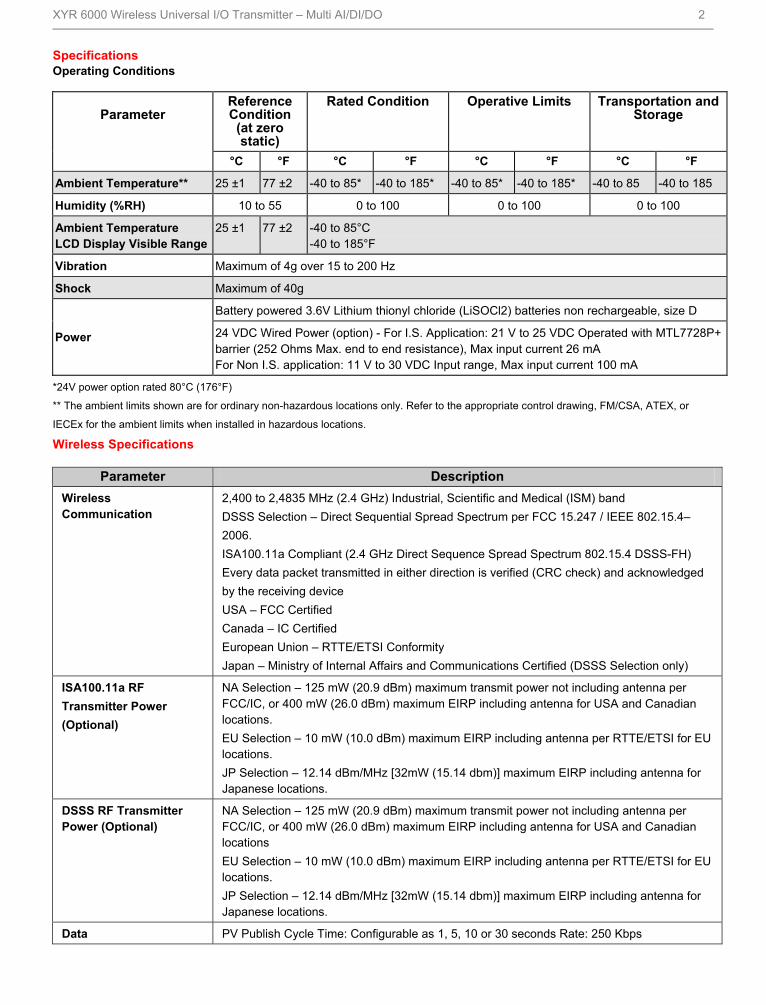
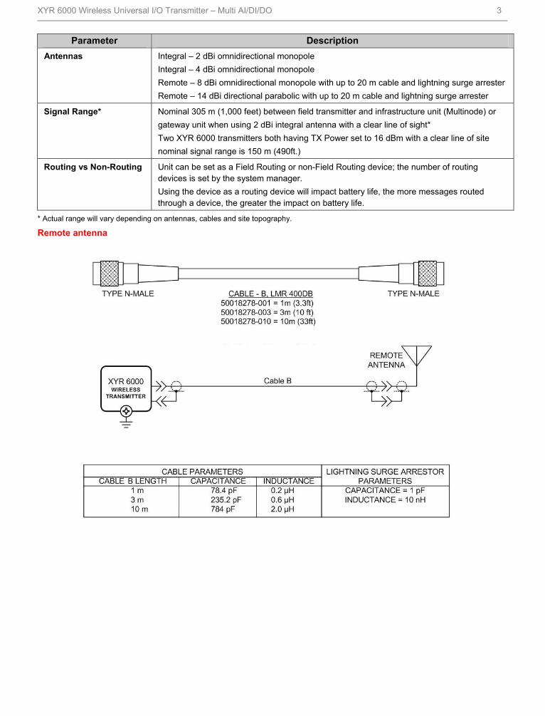
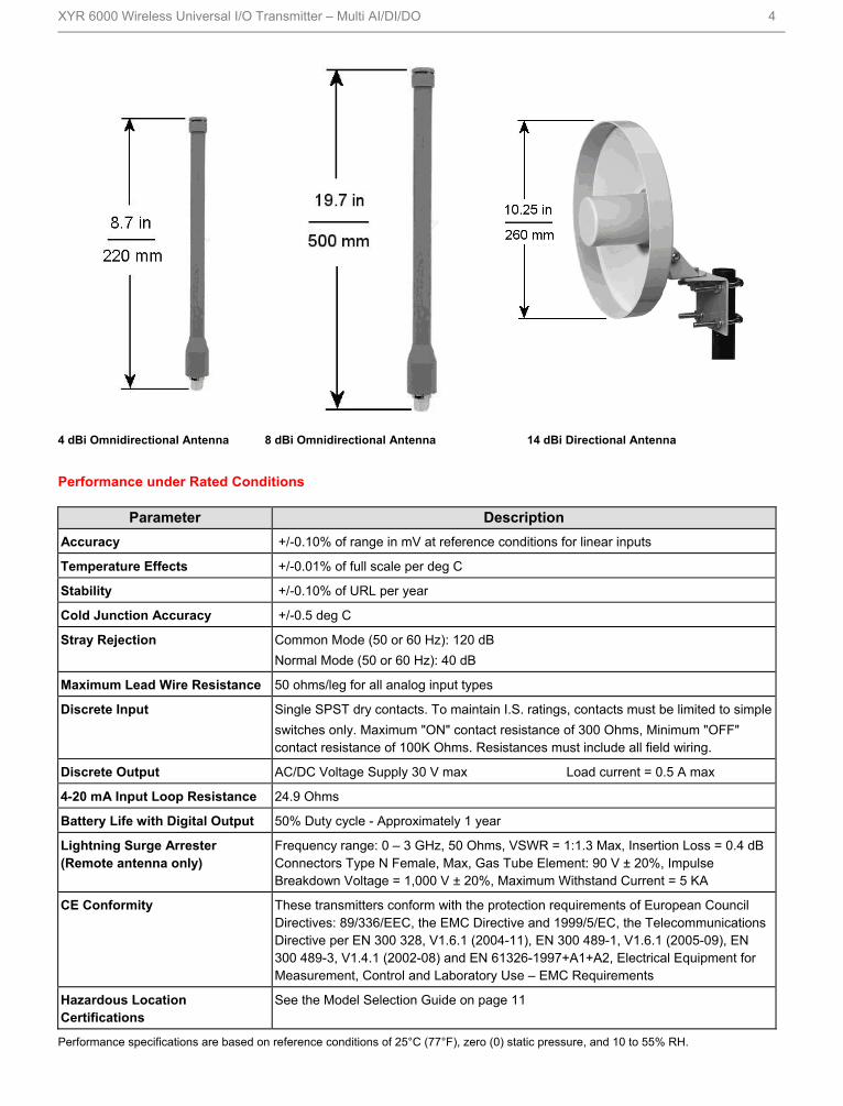
Antennas Integral – 2 dBi omnidirectional monopole
Integral – 4 dBi omnidirectional monopole
Remote – 8 dBi omnidirectional monopole with up to 20 m cable and lightning surge arrester
Remote – 14 dBi directional parabolic with up to 20 m cable and lightning surge arrester
Signal Range* Nominal 305 m (1,000 feet) between field transmitter and infrastructure unit (Multinode) or
gateway unit when using 2 dBi integral antenna with a clear line of sight*
Two XYR 6000 transmitters both having TX Power set to 16 dBm with a clear line of site
nominal signal range is 150 m (490ft.)
Routing vs Non-Routing Unit can be set as a Field Routing or non-Field Routing device; the number of routing devices is set by the system manager.
Using the device as a routing device will impact battery life, the more messages routed through a device, the greater the impact on battery life.
* Actual range will vary depending on antennas, cables and site topography.
Remote antenna
XYR 6000 Wireless Universal I/O Transmitter – Multi AI/DI/DO 4
4 dBi Omnidirectional Antenna 8 dBi Omnidirectional Antenna 14 dBi Directional Antenna
Performance under Rated Conditions
Parameter Description
Accuracy +/-0.10% of range in mV at reference conditions for linear inputs
Temperature Effects +/-0.01% of full scale per deg C
Stability +/-0.10% of URL per year
Cold Junction Accuracy +/-0.5 deg C
Stray Rejection Common Mode (50 or 60 Hz): 120 dB
Normal Mode (50 or 60 Hz): 40 dB
Maximum Lead Wire Resistance 50 ohms/leg for all analog input types
Discrete Input Single SPST dry contacts. To maintain I.S. ratings, contacts must be limited to simple
switches only. Maximum "ON" contact resistance of 300 Ohms, Minimum "OFF" contact resistance of 100K Ohms. Resistances must include all field wiring.
Discrete Output AC/DC Voltage Supply 30 V max Load current = 0.5 A max
4-20 mA Input Loop Resistance 24.9 Ohms
Battery Life with Digital Output 50% Duty cycle - Approximately 1 year
Lightning Surge Arrester (Remote antenna only)
Frequency range: 0 – 3 GHz, 50 Ohms, VSWR = 1:1.3 Max, Insertion Loss = 0.4 dB Connectors Type N Female, Max, Gas Tube Element: 90 V ± 20%, Impulse Breakdown Voltage = 1,000 V ± 20%, Maximum Withstand Current = 5 KA
CE Conformity These transmitters conform with the protection requirements of European Council Directives: 89/336/EEC, the EMC Directive and 1999/5/EC, the Telecommunications Directive per EN 300 328, V1.6.1 (2004-11), EN 300 489-1, V1.6.1 (2005-09), EN 300 489-3, V1.4.1 (2002-08) and EN 61326-1997+A1+A2, Electrical Equipment for Measurement, Control and Laboratory Use – EMC Requirements
Hazardous Location Certifications
See the Model Selection Guide on page 11
Performance specifications are based on reference conditions of 25°C (77°F), zero (0) static pressure, and 10 to 55% RH.

XYR 6000 Wireless Universal I/O Transmitter – Multi AI/DI/DO 5
Physical Specifications
Parameter Description
Mounting Bracket Carbon Steel (Zinc-plated) or Stainless Steel angle bracket or Carbon Steel flat bracket available (standard options).
Terminal Assembly Wiring Gauge Range
28 to 16
Electronic Housing
Stainless Steel Housing (option)
Epoxy-Polyester hybrid paint. Low Copper-Aluminum. Meets NEMA 4X (hosedown and corrosion resistant), IP 66/67 (hosedown and submersible to 1m).
316 SS Electronics Housing - with M20 Conduit Connections
316 SS Housing with 1/2" NPT Conduit Connection
316 SS or Grade CF8M, the casting equivalent of 316 SS with M20 or 1/2" NPT Conduit Connection.
If ordered with the Remote Antenna options, the antenna parts are not SS or Marine type cables; the integral antenna uses SS parts.
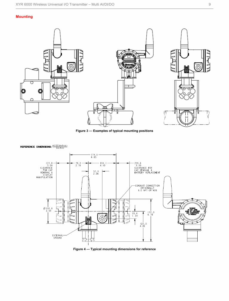
Mounting Can be mounted in virtually any position using the standard mounting bracket. Mounting should result in the antenna being vertically oriented. Bracket is designed to mount on 2-inch (50 mm) vertical or horizontal pipe. See Figure 3.
Dimensions See Figure 4
Net Weight Approximately 9 pounds (4.1 Kg)
STUW700
The Universal I/O transmitter can be commissioned, using Wireless Builder block instantiation, for the following channel I/O
combinations, according to model number.
Channel 1 Channel 2 Channel 3
DI DI HLAI
DI HLAI HLAI
DI T/C or mV HLAI
HLAI DI HLAI
HLAI HLAI HLAI
HLAI T/C or mV HLAI
T/C or mV DI HLAI
T/C or mV HLAI HLAI
T/C or mV T/C or mV HLAI

XYR 6000 Wireless Universal I/O Transmitter – Multi AI/DI/DO 6
STUW701
Channel 1 Channel 2 Channel 3
DI DI DO
DI HLAI DO
DI T/C or mV DO
HLAI DI DO
HLAI HLAI DO
HLAI T/C or mV DO
T/C or mV HLAI DO
T/C or mV DI DO
T/C or mV T/C or mV DO
Up to 2 T/C, millivolt or DI (contact closure) channels
Channel 3 must be HLAI (STUW700) or DO (STUW701)
T/C and millivolt ranges
Thermocouple (B ,E, J, K, N, R, S, T) (all models)
mV (0 to 10, 0 to 50, 0 to 100) (all models)
HLAI input ranges
Current only (0-20 mA, 4-20 mA) (all models)
The transmitter measures the analog signal from temperature sensors, discrete inputs, millivolt or high-level analog inputs
and transmits a digital output signal proportional to the measured value for direct digital communications with systems.
TC & mV Input Types and Ranges Input Type Range Deg F Range Deg C
Type B T/C 0 to 3000 -18 to 1816
Type E T/C -454 to 1832 -270 to 100
Type J T/C 0 to 1600 -18 to 871
Type K T/C 0 to 2400 -18 to 1333
Type N T/C 0 to 2372 -18 to 1300
Type R T/C 0 to 3100 -18 to 1704
Type S T/C 0 to 3100 -18 to 1704
Type T T/C -300 to 700 -18 to 371
Linear Ranges
0 to 10 mV
0 to 50 mV
0 to 100 mV
High Level Analog Input Ranges
0 to 20 mA / 4-20 mA
Discrete Input
300 Ohms Max ON Contact Resistance
100K Ohms Minimum OFF Contact Resistance

XYR 6000 Wireless Universal I/O Transmitter – Multi AI/DI/DO 7
Wiring for calibration – XYR 6000 Universal I/O Wiring Diagrams for AI/DI (Model STUW700)
PV1 Possible Connections T/C, DI or HLAI
PV2 Possible Connections T/C, DI or HLAI
PV3 Possible Connections (HLAI only)
Note: any combination of the above are allowed.
For example: PV1 is a DI, PV2 is 4-20 mA, and PV3 is 0-20 mA.
Or PV1 is 0-20 mA, PV2 is a T/C, PV3 is 0-20 mA
XYR 6000 Wireless Universal I/O Transmitter – Multi AI/DI/DO 8
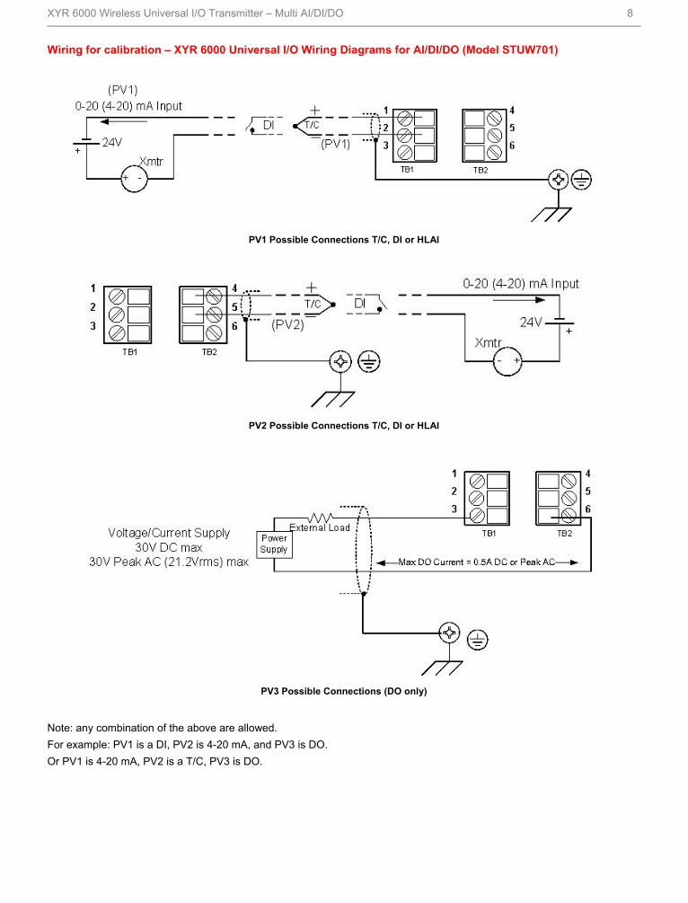
Wiring for calibration – XYR 6000 Universal I/O Wiring Diagrams for AI/DI/DO (Model STUW701)
PV1 Possible Connections T/C, DI or HLAI
PV2 Possible Connections T/C, DI or HLAI
PV3 Possible Connections (DO only)
Note: any combination of the above are allowed.
For example: PV1 is a DI, PV2 is 4-20 mA, and PV3 is DO.
Or PV1 is 4-20 mA, PV2 is a T/C, PV3 is DO.
XYR 6000 Wireless Universal I/O Transmitter – Multi AI/DI/DO 9
Mounting
Figure 3 — Examples of typical mounting positions
Figure 4 — Typical mounting dimensions for reference

XYR 6000 Wireless Universal I/O Transmitter – Multi AI/DI/DO 10
Options
Mounting Bracket
The angle mounting bracket is available in either zinc-
plated carbon steel or stainless steel and is suitable for
horizontal or vertical mounting on a two inch (50
millimeter) pipe, as well as wall mounting. An optional flat
mounting bracket is also available in carbon steel for two
inch (50 millimeter) pipe mounting.
Tagging (Option TG)
Up to 30 characters can be added on the stainless steel
nameplate mounted on the transmitter’s electronics
housing at no extra cost. A stainless steel wired on tag
with additional data of up to 4 lines of 28 characters is
also available. The number of characters for tagging
includes spaces.
Transmitter Configuration
All configurable parameters are accessible via the
OneWireless network via READ/WRITE transactions.

XYR 6000 Wireless Universal I/O Transmitter – Multi AI/DI/DO 11
Model Selection Guides are subject to change and are inserted into the specifications as guidance only.
Prior to specifying or ordering a model check for the latest revision Model Selection Guides which are published at:
http://hpsweb.honeywell.com/Cultures/en-US/Products/Instrumentation/ProductModelSelectionGuides/default.htm

XYR 6000 Wireless Universal I/O Transmitter – Multi AI/DI/DO 12
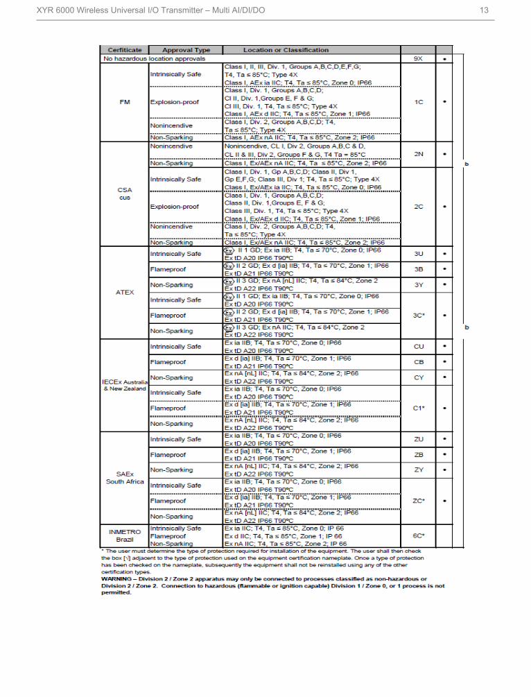
XYR 6000 Wireless Universal I/O Transmitter – Multi AI/DI/DO 13

XYR 6000 Wireless Universal I/O Transmitter – Multi AI/DI/DO 14

XYR 6000 Wireless Universal I/O Transmitter – Multi AI/DI/DO 15
OneWireless and XYR are trademarks and Experion is a registered trademark of Honeywell International Inc
Specifications are subject to change without notice.
For More Information
Learn more about how Honeywell’s Wireless Universal I/O
Transmitter – Multi AI/DI/DO can improve monitoring
capabilities by automating the collection of information,
visit our website www.honeywell.com/ps/hfs or contact
your Honeywell account manager.
Honeywell Process Solutions
1860 West Rose Garden Lane
Phoenix, Arizona 85027
Tel: 1-800-423-9883 or 1-800-343-0228 www.honeywell.com/ps
34-XY-03-36 December 2010 © 2011 Honeywell International Inc.